Floating Point Adder/Subtractor (ALTFP ADD SUB ... · PDF file101 Innovation Drive San Jose,...
40
101 Innovation Drive San Jose, CA 95134 www.altera.com Floating Point Adder/Subtractor (ALTFP_ADD_SUB) Megafunction User Guide Software Version: 8.0 Document Version: 4.0 Document Date: June 2008
Transcript of Floating Point Adder/Subtractor (ALTFP ADD SUB ... · PDF file101 Innovation Drive San Jose,...
101 Innovation DriveSan Jose, CA 95134www.altera.com
Floating Point Adder/Subtractor(ALTFP_ADD_SUB)
Megafunction User Guide
Software Version: 8.0Document Version: 4.0Document Date: June 2008

Copyright © 2008 Altera Corporation. All rights reserved. Altera, The Programmable Solutions Company, the stylized Altera logo, specific device des-ignations, and all other words and logos that are identified as trademarks and/or service marks are, unless noted otherwise, the trademarks andservice marks of Altera Corporation in the U.S. and other countries. All other product or service names are the property of their respective holders. Al-tera products are protected under numerous U.S. and foreign patents and pending applications, maskwork rights, and copyrights. Altera warrantsperformance of its semiconductor products to current specifications in accordance with Altera's standard warranty, but reserves the right to makechanges to any products and services at any time without notice. Altera assumes no responsibility or liability arising out of the ap-plication or use of any information, product, or service described herein except as expressly agreed to in writing by AlteraCorporation. Altera customers are advised to obtain the latest version of device specifications before relying on any published in-formation and before placing orders for products or services.
ii Altera CorporationALTFP_ADD_SUB Megafunction User GuideConfidential—Internal Use Only June 2008
UG-041305-4.0

Altera Corporation Confidential—Internal Use Only iiiALTFP_ADD_SUB Megafunction User Guide
Contents
Chapter 1. About this MegafunctionDevice Family Support ......................................................................................................................... 1–1Introduction ............................................................................................................................................ 1–1Features ................................................................................................................................................... 1–1General Description ............................................................................................................................... 1–2
The Format ........................................................................................................................................ 1–3Single-Precision Format ............................................................................................................. 1–3Double-Precision Format ........................................................................................................... 1–3Single-Extended Precision Format ........................................................................................... 1–3
Special-Case Numbers ..................................................................................................................... 1–4Rounding ........................................................................................................................................... 1–4Algorithm for Floating-Point Adder/Subtractor ........................................................................ 1–4Exception Handling ......................................................................................................................... 1–5
Common Applications .......................................................................................................................... 1–5Resource Utilization and Performance ............................................................................................... 1–6
Chapter 2. Getting StartedSoftware and System Requirements ................................................................................................... 2–1MegaWizard Plug-In Manager Customization ................................................................................. 2–1MegaWizard Page Descriptions .......................................................................................................... 2–1Instantiating Megafunctions in HDL Code or Schematic Designs ................................................. 2–9
Generating a Netlist for EDA Tool Use ......................................................................................... 2–9Using the Port and Parameter Definitions .................................................................................. 2–10
Identifying a Megafunction after Compilation ............................................................................... 2–10Simulation ............................................................................................................................................. 2–10
Quartus II Simulation .................................................................................................................... 2–10EDA Simulator ................................................................................................................................ 2–11
Design Example: Addition of Double-Precision Numbers ........................................................... 2–12Design Files ..................................................................................................................................... 2–12Procedure ......................................................................................................................................... 2–12Generate the Adder ........................................................................................................................ 2–12Implement the Adder .................................................................................................................... 2–14Functional Simulation in the ModelSim-Altera Software ........................................................ 2–16Understanding the Simulation Results ....................................................................................... 2–17
Truth Table ........................................................................................................................................... 2–19Conclusion ............................................................................................................................................ 2–20
Chapter 3. SpecificationsPorts and Parameters ............................................................................................................................ 3–1

iv Confidential—Internal Use Only Altera CorporationALTFP_ADD_SUB Megafunction User Guide
Contents
Additional InformationRevision History ............................................................................................................................... Info–1Referenced Documents .................................................................................................................... Info–2How to Contact Altera ..................................................................................................................... Info–2Typographic Conventions ............................................................................................................... Info–3

Altera Corporation Confidential—Internal Use Only 1–1June 2008 ALTFP_ADD_SUB Megafunction User Guide
Chapter 1. About thisMegafunction
Device Family Support
The ALTFP_ADD_SUB megafunction supports the following target Altera® device families:
■ Arria® GX■ Stratix® IV■ Stratix III■ Stratix II■ Stratix II GX■ Stratix■ Stratix GX■ Cyclone® III■ Cyclone II■ Cyclone■ HardCopy® II■ HardCopy Stratix
Introduction As design complexities increase, the use of vendor-specific intellectual property (IP) blocks has become a common design methodology. Altera provides parameterizable megafunctions that are optimized for Altera device architectures. Using megafunctions instead of coding your own logic saves valuable design time. Additionally, the Altera-provided functions may offer more efficient logic synthesis and device implementation. You can scale the size of the megafunction by setting parameters.
Features The ALTFP_ADD_SUB megafunction implements a floating-point adder/subtractor and offers many features, including the following:
■ Addition or subtraction of single-precision, single-extended, and double-precision numbers
■ Operating modes such as addition only, subtraction only, or addition and subtraction
■ Support for input of normal numbers, infinity, zero, and not-a-number (NaN)
■ Optional input ports such as asynchronous clear (aclr) and clock enable (clk_en)
■ Optional exception-handling output ports such as zero, overflow, underflow, and nan
■ Optimization to obtain better performances in speed and area

1–2 Confidential—Internal Use Only Altera CorporationALTFP_ADD_SUB Megafunction User Guide June 2008
General Description
General Description
The ALTFP_ADD_SUB megafunction follows the IEEE 754-1985 Standard for Binary Floating-Point Arithmetic. Due to performance constraints, only a subset of this standard is implemented in the ALTFP_ADD_SUB megafunction. This standard gives an overview of floating point and its representation, including:
■ Floating-point numbers■ Special values such as zero, infinity, and bit combinations that do not
represent a number (NaN)■ Special operations■ Rounding modes■ Operations that work identically on conforming systems
The IEEE 754-1985 standard defines four formats for floating-point numbers, of which two are commonly used (single and double). In single-precision numbers, there is a 1-bit sign and 23 bits in the mantissa (an implicit 24th bit is the leading 1 in all mantissas, which is not stored). The 8-bit exponent has a range from –126 to 127 with a bias of 127. In double-precision numbers, there is a 1-bit sign and 53 bits of precision in the mantissa (52 bits and one implied leading 1 bit). The exponent ranges from –1022 to 1023 with a bias of 1023.
The other two formats are extended versions of the two common representations. The extended formats do not have defined biases. However, the implementation of this megafunction assumes a bias of 2(E–1)–1. Although four different formats are defined in the standard, the ALTFP_ADD_SUB megafunction supports only single-precision, double-precision, and single-extended precision formats. The double-extended precision format is not supported.
Table 1–1 shows the number of data bits for the sign, exponent, and mantissa fields for floating-point numbers in the various precision modes.
Table 1–1. Data Bit(s) of Sign, Exponent, and Mantissa Fields for Floating-Point Numbers
Precision Mode Sign Bits (S) Exponent Bits (E)
Mantissa Bits (M)
TotalBits Bias of 2(E–1) –1
Single 1 8 23 32 127
Double 1 11 52 64 1023
Single Extended1 ≥ 11 ≥ 31 ≥ 43 Unspecified. Assume 2(E–1)–1
1 < M width ≥ 31 ≤ 64 Unspecified. Assume 2(E–1)–1

Altera Corporation Confidential—Internal Use Only 1–3June 2008 ALTFP_ADD_SUB Megafunction User Guide
About this Megafunction
The Format
Three distinct formats—single-precision, double-precision, and single-extended precision—are available to represent floating-point numbers.
Single-Precision Format
In single-precision format, the most significant bit (MSB) is a sign bit, followed by 8 intermediate bits to represent an exponent, and 23 least significant bits (LSBs) to represent the mantissa. As a result, the total width in the single-precision format is 32 bits. The bias for single-precision format is 127. See Figure 1–1.
Figure 1–1. Single-Precision Representation
Double-Precision Format
In double-precision format, the MSB is a sign bit, followed by 11 intermediate bits to represent an exponent, and 52 LSBs to represent the mantissa. As a result, the total width in the double-precision format is 64 bits. The bias for double-precision format is 1023. See Figure 1–2.
Figure 1–2. Double-Precision Representation
Single-Extended Precision Format
In single-extended precision format, the MSB is a sign bit. However, there are no fixed widths for the exponent and mantissa fields. The exponent field has a minimum of 11 bits and its width must be less than the width of the mantissa field. The mantissa field has a minimum of 31 bits. The sum of the width of the sign bit, the exponent field, and the mantissa field
31 30 23 22 0
S E M
63 62 52 51 0
S E M
1–4 Confidential—Internal Use Only Altera CorporationALTFP_ADD_SUB Megafunction User Guide June 2008
General Description
has a minimum of 43 bits and a maximum of 64 bits. The bias for the single-extended precision format is unspecified in the IEEE-754 standard. In this adder/subtractor, a bias of 2(WIDTH_EXP–1)–1 is assumed for single-extended precision.
Special-Case Numbers
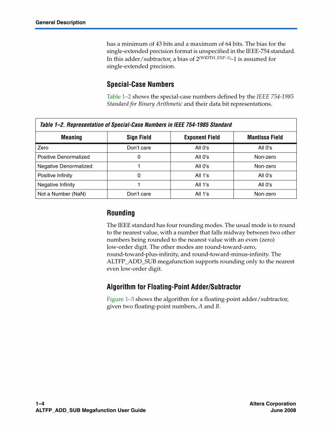
Table 1–2 shows the special-case numbers defined by the IEEE 754-1985 Standard for Binary Arithmetic and their data bit representations.
Rounding
The IEEE standard has four rounding modes. The usual mode is to round to the nearest value, with a number that falls midway between two other numbers being rounded to the nearest value with an even (zero) low-order digit. The other modes are round-toward-zero, round-toward-plus-infinity, and round-toward-minus-infinity. The ALTFP_ADD_SUB megafunction supports rounding only to the nearest even low-order digit.
Algorithm for Floating-Point Adder/Subtractor
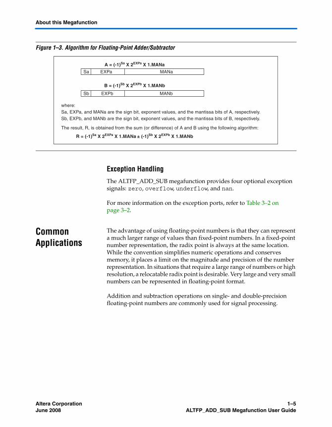
Figure 1–3 shows the algorithm for a floating-point adder/subtractor, given two floating-point numbers, A and B.
Table 1–2. Representation of Special-Case Numbers in IEEE 754-1985 Standard
Meaning Sign Field Exponent Field Mantissa Field
Zero Don’t care All 0's All 0's
Positive Denormalized 0 All 0's Non-zero
Negative Denormalized 1 All 0's Non-zero
Positive Infinity 0 All 1's All 0's
Negative Infinity 1 All 1's All 0's
Not a Number (NaN) Don’t care All 1's Non-zero
Altera Corporation Confidential—Internal Use Only 1–5June 2008 ALTFP_ADD_SUB Megafunction User Guide
About this Megafunction
Figure 1–3. Algorithm for Floating-Point Adder/Subtractor
Exception Handling
The ALTFP_ADD_SUB megafunction provides four optional exception signals: zero, overflow, underflow, and nan.
For more information on the exception ports, refer to Table 3–2 on page 3–2.
Common Applications
The advantage of using floating-point numbers is that they can represent a much larger range of values than fixed-point numbers. In a fixed-point number representation, the radix point is always at the same location. While the convention simplifies numeric operations and conserves memory, it places a limit on the magnitude and precision of the number representation. In situations that require a large range of numbers or high resolution, a relocatable radix point is desirable. Very large and very small numbers can be represented in floating-point format.
Addition and subtraction operations on single- and double-precision floating-point numbers are commonly used for signal processing.
A = (-1)Sa X 2EXPa X 1.MANa
R = (-1)Sa X 2EXPa X 1.MANa ± (-1)Sb X 2EXPb X 1.MANb
B = (-1)Sb X 2EXPb X 1.MANb
where:Sa, EXPa, and MANa are the sign bit, exponent values, and the mantissa bits of A, respectively.Sb, EXPb, and MANb are the sign bit, exponent values, and the mantissa bits of B, respectively.
The result, R, is obtained from the sum (or difference) of A and B using the following algorithm:
Sa EXPa MANa
Sb EXPb MANb

1–6 Confidential—Internal Use Only Altera CorporationALTFP_ADD_SUB Megafunction User Guide June 2008
Resource Utilization and Performance
Resource Utilization and Performance
Table 1–3 summarizes the resource usage by the ALTFP_ADD_SUB megafunction for selected devices in the Stratix II and Stratix III device families.
Table 1–4 summarizes the resource usage by the ALTFP_ADD_SUB megafunction for selected devices in the Cyclone II and Cyclone III device families.
Table 1–3. ALTFP_ADD_SUB Resource Usage for Stratix II and Stratix III Devices Note (1)
Device Family
Precision Optimization Output Latency(Cycles)
Adaptive Look-Up Tables
(ALUTs)
Dedicated Logic
Registers (DLRs)
Logic Usage fMAX
Stratix II Single Speed 7 613 347 673 260
Area 7 567 317 627 250
Double Speed 7 1280 649 1425 209
Area 7 1175 591 1320 166
Stratix III Single Speed 7 627 375 704 303
Area 7 582 346 653 307
Double Speed 7 1295 683 1440 251
Area 7 1196 626 1322 219
Note to Table 1–3:(1) The MegaWizard Plug-In Manager provides performance information. All information in this table is correct in the
Quartus II software version 8.0.
Table 1–4. ALTFP_ADD_SUB Resource Usage for Cyclone II and Cyclone III Devices (Part 1 of 2) Note (1)
Device Family
Precision Optimization Output Latency(Cycles)
Logic Elements
(LEs)
Dedicated Logic
Registers (DLRs)
Logic Usage fMAX
Cyclone II Single Speed 7 831 346 831 153
Area 7 785 317 785 143
Double Speed 7 1764 648 1764 119
Area 7 1656 591 1656 101

Altera Corporation Confidential—Internal Use Only 1–7June 2008 ALTFP_ADD_SUB Megafunction User Guide
About this Megafunction
Cyclone III Single Speed 7 822 346 822 154
Area 7 775 317 775 149
Double Speed 7 1743 648 1743 128
Area 7 1631 591 1631 116
Note to Table 1–4:(1) The MegaWizard Plug-In Manager provides performance information. All information in this table is correct in the
Quartus II software version 8.0.
Table 1–4. ALTFP_ADD_SUB Resource Usage for Cyclone II and Cyclone III Devices (Part 2 of 2) Note (1)
Device Family
Precision Optimization Output Latency(Cycles)
Logic Elements
(LEs)
Dedicated Logic
Registers (DLRs)
Logic Usage fMAX

1–8 Confidential—Internal Use Only Altera CorporationALTFP_ADD_SUB Megafunction User Guide June 2008
Resource Utilization and Performance
Altera Corporation Confidential—Internal Use Only 2–1June 2008 ALTFP_ADD_SUB Megafunction User Guide
Chapter 2. Getting Started
Software and System Requirements
The instructions in this section require the following software:
■ Quartus® II software version 7.2 or later■ For operating system support information, refer to:
www.altera.com/support/software/os_support/oss-index.html
MegaWizard Plug-In Manager Customization
Use the MegaWizard® Plug-In Manager to create or modify design files that contain custom megafunction variations, which can then be instantiated in a design file. The MegaWizard Plug-In Manager provides a wizard that allows you to specify options for the ALTFP_ADD_SUB megafunction features in your design.
Start the MegaWizard Plug-In Manager in one of the following ways:
■ On the Tools menu, click the MegaWizard Plug-In Manager option.■ When working in the Block Editor, from the Edit menu, click Insert
Symbol as Block, or right-click in the Block Editor, point to Insert, and click Symbol as Block. In the Symbol window, click MegaWizard Plug-In Manager.
■ Start the stand-alone version of the MegaWizard Plug-In Manager by typing the following command at the command prompt:qmegawizr
MegaWizard Page Descriptions
This section provides descriptions of the options available on the individual pages of the ALTFP_ADD_SUB wizard.
On page 1 of the MegaWizard Plug-In Manager, you can select Create a new custom megafunction variation, Edit an existing custom megafunction variation, or Copy an existing custom megafunction variation (Figure 2–1).

2–2 Confidential—Internal Use Only Altera CorporationALTFP_ADD_SUB Megafunction User Guide June 2008
MegaWizard Page Descriptions
Figure 2–1. MegaWizard Plug-In Manager [page 1]
On page 2a of the MegaWizard Plug-In Manager, specify the megafunction, device family, type of output file to create, and the name of the output file (Figure 2–2). Choose AHDL (.tdf), VHDL (.vhd), or Verilog HDL (.v) as the output file type.
Figure 2–2. MegaWizard Plug-In Manager [page 2a]

Altera Corporation Confidential—Internal Use Only 2–3June 2008 ALTFP_ADD_SUB Megafunction User Guide
Getting Started
On page 3 of the ALTFP_ADD_SUB MegaWizard Plug-In Manager, you can select the floating-point format, verify the widths of input and output buses, verify the widths of the exponent and mantissa, specify the output latency in clock cycles, and select the operating mode (Figure 2–3).
Figure 2–3. ALTFP_ADD_SUB MegaWizard Plug-In Manager [page 3 of 7]

2–4 Confidential—Internal Use Only Altera CorporationALTFP_ADD_SUB Megafunction User Guide June 2008
MegaWizard Page Descriptions
Table 2–1 shows the options available on page 3 of the ALTFP_ADD_SUB wizard.
Table 2–1. ALTFP_ADD_SUB MegaWizard Plug-In Manager [page 3] Options
Function Description
Currently selected device family Specify the device family you want to use.
What is the floating-point format? Select single precision for 32 bits, double precision for 64 bits, and single-extended precision for 43 to 64 bits.
How wide should the ‘dataa’ input, ‘datab’ input, and ‘result’ output buses be?
Specify the widths of the buses for single-extended precision format. The maximum width is 32 bits for single precision, 64 bits for double precision, and 64 bits for single-extended precision. In single- and double-precision formats, the bus width is fixed. You can specify the widths of buses for single-extended precision format only.
How wide should the exponent field be? Specify the width of the exponent field for single-extended precision format. The maximum is 31 bits. In single- and double-precision formats, the exponent field width is fixed. You can specify the width of the exponent field for single-extended precision format only.
Mantissa width = (data input width)–(exponent field width)–1
This value is automatically calculated when the widths of the exponent field and input buses are specified.
What is the output latency in clock cycles?
Specify the latency for the result in clock cycles. Latencies of 7 to 14 clock cycles are available.
Which operating mode do you want for the adder/ subtractor?
Allows you to select one of these operating modes:● Specify Addition only to use the function as an adder● Specify Subtraction only to use the function as a subtractor● Specify Create an ‘add_sub’ input port to do both to use the
function as an adder and a subtractor

Altera Corporation Confidential—Internal Use Only 2–5June 2008 ALTFP_ADD_SUB Megafunction User Guide
Getting Started
On page 4 of the ALTFP_ADD_SUB MegaWizard Plug-In Manager, you can create optional input ports and select optional exception ports for your design (Figure 2–4).
Figure 2–4. ALTFP_ADD_SUB MegaWizard Plug-In Manager [page 4 of 7]

2–6 Confidential—Internal Use Only Altera CorporationALTFP_ADD_SUB Megafunction User Guide June 2008
MegaWizard Page Descriptions
On page 5 of the ALTFP_ADD_SUB MegaWizard Plug-In Manager, you can select the type of optimization to implement (Figure 2–5).
Figure 2–5. ALTFP_ADD_SUB MegaWizard Plug-In Manager [page 5 of 7]

Altera Corporation Confidential—Internal Use Only 2–7June 2008 ALTFP_ADD_SUB Megafunction User Guide
Getting Started
On page 6 of the ALTFP_ADD_SUB MegaWizard Plug-In Manager, you can choose to generate a synthesis area and timing estimation netlist (Figure 2–6).
Figure 2–6. ALTFP_ADD_SUB MegaWizard Plug-In Manager [page 6 of 7]

2–8 Confidential—Internal Use Only Altera CorporationALTFP_ADD_SUB Megafunction User Guide June 2008
MegaWizard Page Descriptions
Page 7 of the ALTFP_ADD_SUB MegaWizard Plug-In Manager displays the types of files to be generated. The Variation file, which is automatically generated, contains wrapper code in the language you specified on page 2a. On page 7 of the ALTFP_ADD_SUB MegaWizard Plug-In Manager, specify the types of files to be generated. You can choose from the following types of files:
■ AHDL Include file (<function name>.inc)■ VHDL component declaration file (<function name>.cmp)■ Quartus II symbol file (<function name>.bsf)■ Instantiation template file (<function name>_inst.v)■ Verilog HDL black-box declaration file (<function name>_bb.v)
If you selected Generate netlist on page 6, the file for that netlist is also available. A gray checkmark indicates a file that is automatically generated and a red checkmark indicates an optional file (Figure 2–7)
Figure 2–7. ALTFP_ADD_SUB MegaWizard Plug-In Manager [page 7 of 7]
For more information about the ports for the ALTFP_ADD_SUB megafunction, refer to Chapter 3, Specifications.

Altera Corporation Confidential—Internal Use Only 2–9June 2008 ALTFP_ADD_SUB Megafunction User Guide
Getting Started
Instantiating Megafunctions in HDL Code or Schematic Designs
When you use the MegaWizard Plug-In Manager to customize and parameterize a megafunction, it creates a set of output files that allow you to instantiate the customized function in your design. Depending on the language you choose in the MegaWizard Plug-In Manager, the MegaWizard instantiates the megafunction with the correct parameter values and generates a megafunction variation file (wrapper file) in Verilog HDL (.v), VHDL (.vhd), or AHDL (.tdf), along with other supporting files.
The MegaWizard Plug-In Manager provides options to create the following files:
■ A sample instantiation template for the language of the variation file (_inst.v, _inst.vhd, or _inst.tdf)
■ Component Declaration File (.cmp) that can be used in VHDL Design Files
■ ADHL Include File (.inc) that can be used in Text Design Files (.tdf)■ Quartus II Block Symbol File (.bsf) that can be used in schematic
designs■ Verilog HDL module declaration file that can be used when
instantiating the megafunction as a black box in a third-party synthesis tool (_bb.v)
f For more information about the wizard-generated files, refer to the Quartus II Help or to the Recommended HDL Coding Styles chapter in volume 1 of the Quartus II Handbook.
Generating a Netlist for EDA Tool Use
If you use a third-party EDA synthesis tool, you can instantiate the megafunction variation file as a black box for synthesis. Use the VHDL component declaration or Verilog module declaration black-box file to define the function in your synthesis tool, and then include the megafunction variation file in your Quartus II project.
If you enable the option to generate a synthesis area and timing estimation netlist in the MegaWizard Plug-In Manager, an additional netlist file (_syn.v) is generated. The netlist file is a representation of the customized logic used in the Quartus II software. The file provides the connectivity of the architectural elements in the megafunction but may not represent true functionality. This information enables certain third-party synthesis tools to better report area and timing estimates. In addition, synthesis tools can use the timing information to focus timing-driven optimizations and improve the quality of results.

2–10 Confidential—Internal Use Only Altera CorporationALTFP_ADD_SUB Megafunction User Guide June 2008
Identifying a Megafunction after Compilation
f For more information about using megafunctions in your third-party synthesis tool, refer to the appropriate chapter in the Synthesis section in volume 1 of the Quartus II Handbook.
Using the Port and Parameter Definitions
Instead of using the MegaWizard Plug-In Manager, you can instantiate the megafunction directly in your Verilog HDL, VHDL, or AHDL code by calling the megafunction and setting its parameters as you would any other module, component, or subdesign.
1 Altera strongly recommends that you use the MegaWizard Plug-In Manager for complex megafunctions. The MegaWizard Plug-In Manager ensures that you set all megafunction parameters properly.
Refer to Chapter 3, Specifications for a list of the megafunction ports and parameters.
Identifying a Megafunction after Compilation
During compilation with the Quartus II software, analysis and elaboration is performed to build the structure of your design. To locate your megafunction in the Project Navigator window, expand the compilation hierarchy and find the megafunction by its name.
To search for node names within the megafunction (using the Node Finder), click Browse in the Look in box and select the megafunction in the Hierarchy box.
Simulation The Quartus II Simulation tool provides an easy-to-use, integrated solution for performing simulations. The following sections describe the simulation options.
Quartus II Simulation
With the Quartus II Simulator, you can perform two types of simulations: functional and timing. A functional simulation in the Quartus II program enables you to verify the logical operation of your design without taking into consideration the timing delays in the FPGA. This simulation is performed using only RTL code. When performing a functional simulation, you are able to view signals that exist before synthesis. You can find these signals with the Registers: pre-synthesis, Design Entry, or Pin filters in the Node Finder. These three filters find the top-level ports of megafunctions.

Altera Corporation Confidential—Internal Use Only 2–11June 2008 ALTFP_ADD_SUB Megafunction User Guide
Getting Started
In contrast, timing simulation in the Quartus II software verifies the operation of your design with annotated timing information. This simulation is performed using the post-place-and-route netlist. When performing a timing simulation, you are able to view signals that exist after place-and-route. These signals are found with the post-compilation filter of the Node Finder. During synthesis and place-and-route, the names of RTL signals change. Therefore, it might be difficult to find signals from your megafunction instantiation in the post-compilation filter.
To preserve the names of your signals during the synthesis and place-and-route stages, use the synthesis attributes keep or preserve. These are Verilog and VHDL synthesis attributes that direct analysis and synthesis to keep a particular wire, register, or node intact. Use these synthesis attributes to keep a combinational logic node so you can observe the node during simulation.
f For more information about these attributes, refer to the Quartus II Integrated Synthesis chapter in volume 1 of the Quartus II Handbook.
EDA Simulator
The Quartus II Handbook chapters describe how to perform functional and gate-level timing simulations that include the megafunctions, with details about the files that are needed and the directories where the files are located.
Depending on which simulation tool you are using, refer to the appropriate chapter in the Simulation section in volume 3 of the Quartus II Handbook.

2–12 Confidential—Internal Use Only Altera CorporationALTFP_ADD_SUB Megafunction User Guide June 2008
Design Example: Addition of Double-Precision Numbers
Design Example: Addition of Double-Precision Numbers
This design example uses the ALTFP_ADD_SUB megafunction to implement an adder for the addition of double-precision numbers using the MegaWizard Plug-In Manager in the Quartus II software.
Design Files
The design files are available with this user guide in the Quartus II Project section and in the User Guides section of the Altera website (www.altera.com).
Procedure
In this example, you perform the following activities:
■ Create an adder using the ALTFP_ADD_SUB megafunction and the MegaWizard Plug-In Manager
■ Implement the design and assign the EP2S30F484C3 device to the project
■ Compile and simulate the design
Generate the Adder
To generate the adder, perform the following steps:
1. Open the altfp_add_sub_DesignExample_ex.zip project and extract the fp_add_sub_ex.qar file.
2. In the Quartus II software, open fp_add_sub_ex.qar and restore the archive file into your working directory.
3. On the Tools menu, click MegaWizard Plug-In Manager. Page 1 of the MegaWizard Plug-In Manager appears.
4. Select Create a new custom megafunction variation.
5. Click Next. Page 2a of the MegaWizard Plug-In Manager appears.

Altera Corporation Confidential—Internal Use Only 2–13June 2008 ALTFP_ADD_SUB Megafunction User Guide
Getting Started
6. In the MegaWizard Plug-In Manager pages, select or verify the configuration settings shown in Table 2–2. Click Next to advance from one page to the next.
7. Click Finish. The ALTFP_ADD_SUB module is now built.
Table 2–2. Configuration Settings
MegaWizard Plug-In Manager Page MegaWizard Plug-In Manager Configuration Setting Value
2a Select a megafunction Under Arithmetic, select ALTFP_ADD_SUB
Which device family will you be using? Stratix II
Which type of output file do you want to create? Verilog HDL
What name do you want for the output file? fp_add_sub_ex
3 Currently selected family Stratix II
Match project/default Selected
What is the floating point format? Double precision (64 bits)
How wide should the 'dataa' input, 'datab' input, and 'result' output buses be?
64 bits
How wide should the exponent field be? 11 bits
Mantissa width = (data input width) – (exponent field width) – 1
52 bits
What is the output latency in clock cycles? 7
Which operating mode do you want for the adder/subtractor?
Addition only
4 Do you want to create optional input ports? Select all
Do you want to create optional exception ports? Select all
5 What is the optimization you want to use? Speed
6 Generate netlist Not selected
7 Variation file Selected
AHDL Include file Not selected
VHDL component declaration file Not selected
Quartus II symbol file Selected
Instantiation template file Not selected
Verilog HDL black-box file Selected

2–14 Confidential—Internal Use Only Altera CorporationALTFP_ADD_SUB Megafunction User Guide June 2008
Design Example: Addition of Double-Precision Numbers
Implement the Adder
This section describes how to assign the EP2S30F484C3 device to the project and compile the project.
1. In the Quartus II software, on the Assignments menu, click Settings. The Settings dialog box appears.
2. Under Category, select Device.
3. In the Family list, select Stratix II.
4. Under Target Device, select Specific device selected in ‘Available devices’ list.
5. Turn on Show advanced devices.
6. In the Available devices list, select EP2S30F484C3.
Figure 2–8 shows the Device Settings dialog box after these selections are made.

Altera Corporation Confidential—Internal Use Only 2–15June 2008 ALTFP_ADD_SUB Megafunction User Guide
Getting Started
Figure 2–8. Device Settings Dialog Box
7. Leave the other options in the default state and click OK.
8. On the Processing menu, click Start Compilation to compile the design, or on the toolbar, click the Start Compilation button.
9. When the Full Compilation was successful message box appears, click OK.

2–16 Confidential—Internal Use Only Altera CorporationALTFP_ADD_SUB Megafunction User Guide June 2008
Design Example: Addition of Double-Precision Numbers
Functional Simulation in the ModelSim-Altera Software
Simulate the design in the ModelSim®-Altera software to generate a waveform display of the device behavior.
You should be familiar with the ModelSim-Altera software before trying out the design example. If you are unfamiliar with the ModelSim-Altera software, refer to the support page for software products on the Altera website (www.altera.com). On the support page, there are links to such topics as installation, usage, and troubleshooting.
Set up and simulate the design in the ModelSim-Altera software by performing the following steps:
1. Unzip the altfp_add_sub_ex_msim.zip file to any working directory on your PC.
2. Start the ModelSim-Altera software.
3. On the File menu, click Change Directory.
4. Select the folder in which you unzipped the files.
5. Click OK.
6. On the Tools menu, click Execute Macro.
7. Select the fp_add_sub_ex.do file and click Open. This is a script file for the ModelSim-Altera software to automate all the necessary settings for the simulation.
8. Verify the results shown in the Wave window.
You can rearrange signals, remove signals, add signals, and change the radix by modifying the script in the fp_add_sub_ex.do file.
Figure 2–9 shows the expected simulation results in the ModelSim-Altera software. For more information about the simulation results, refer to “Understanding the Simulation Results” on page 2–17.

Altera Corporation Confidential—Internal Use Only 2–17June 2008 ALTFP_ADD_SUB Megafunction User Guide
Getting Started
Figure 2–9. Simulation Waveform in the ModelSim-Altera Software
Understanding the Simulation Results
This design example implements a floating-point adder for the addition of double-precision numbers. All the optional input ports (clk_en and aclr) and optional output ports (overflow, underflow, zero, and nan) are enabled.
In this example, the latency is set to 7 clock cycles. Every addition result appears at the result[] port 7 clock cycles after the input values are captured on the dataa[] and datab[]ports.
f To view the behavior of the floating-point adder and subtractor, refer to Table 2–3 on page 2–19.
Figure 2–10. Addition of Zero and Infinity Values

2–18 Confidential—Internal Use Only Altera CorporationALTFP_ADD_SUB Megafunction User Guide June 2008
Design Example: Addition of Double-Precision Numbers
Figure 2–10 shows the result of adding zero and infinity values. In Figure 2–10, the values of the dataa[] and datab[] ports are latched at 1250 ns when the aclr signal is deasserted. After 7 clock cycles, at 4250 ns, the addition result appears at the result[] port. The addition of zero at the input port dataa[], and an infinity value at the input port datab[] results in an infinity value and causes the assertion of the overflow port.
Figure 2–11. Addition of Zero and Denormal Values
Figure 2–11 shows the result of adding zero and denormal values. In Figure 2–11, the values of the dataa[] and datab[] ports are latched at 40,750 ns. After 7 clock cycles, at 43,750 ns, the addition result appears at the result[] port. As denormal values are forced-zero values, the addition of zero at the input port dataa[], and a denormal value at the input port datab[] results in a zero. Thus, the zero port remains asserted at 43,750 ns.
Figure 2–12. Addition of Zero and NaN

Altera Corporation Confidential—Internal Use Only 2–19June 2008 ALTFP_ADD_SUB Megafunction User Guide
Getting Started
Figure 2–12 illustrates the result of adding a zero and a NaN. In Figure 2–12, the values of the dataa[] and datab[] ports are latched at 58,250 ns. After 7 clock cycles, at 61,250 ns, the addition results appear at the result[] port. The addition of zero at the input port dataa[], and a NaN at the input port datab[] results in a NaN and causes the assertion of the nan port.
Truth Table Table 2–3 shows the truth table for addition and subtraction operations.
Table 2–3. Truth Table for Addition and Subtraction Operations (Part 1 of 2)
dataa[] datab[] Sign Bit result[] overflow underflow zero nan
Normal Normal 0 Zero 0 0 1 0
Normal Normal 0/1 Normal 0 0 0 0
Normal Normal 0/1 Denormal (1)
0 1 1 0
Normal Normal 0/1 Infinity 1 0 0 0
Normal Denormal 0/1 Normal 0 0 0 0
Normal Zero 0/1 Normal 0 0 0 0
Normal Infinity 0/1 Infinity 1 0 0 0
Normal NaN X NaN 0 0 0 1
Denormal Normal 0/1 Normal 0 0 0 0
Denormal Denormal 0/1 Zero 0 0 1 0
Denormal Zero 0/1 Zero 0 0 1 0
Denormal Infinity 0/1 Infinity 1 0 0 0
Denormal NaN X NaN 0 0 0 1
Zero Normal 0/1 Normal 0 0 0 0
Zero Denormal 0/1 Zero 0 0 1 0
Zero Zero 0/1 Zero 0 0 1 0
Zero Infinity 0/1 Infinity 1 0 0 0
Zero NaN X NaN 0 0 0 1
Infinity Normal 0/1 Infinity 1 0 0 0
Infinity Denormal 0/1 Infinity 1 0 0 0
Infinity Zero 0/1 Infinity 1 0 0 0
Infinity Infinity 0/1 Infinity 1 0 0 0
Infinity NaN X NaN 0 0 0 1
NaN Normal X NaN 0 0 0 1
NaN Denormal X NaN 0 0 0 1

2–20 Confidential—Internal Use Only Altera CorporationALTFP_ADD_SUB Megafunction User Guide June 2008
Conclusion
Conclusion The Quartus II software provides parameterizable megafunctions ranging from simple arithmetic units, such as adders and counters, to advanced phase-locked loop (PLL) blocks, multipliers, and memory structures. These megafunctions are performance-optimized for Altera devices and therefore, provide more efficient logic synthesis and device implementation, because they automate the coding process and save valuable design time. Altera recommends using these functions during design implementation to enable you to consistently meet your design goals.
NaN Zero X NaN 0 0 0 1
NaN Infinity X NaN 0 0 0 1
NaN NaN X NaN 0 0 0 1
Note to Table 2–3:(1) Any calculated or computed denormal output is replaced by a zero. A denormal output also asserts the zero and
underflow signals.
Table 2–3. Truth Table for Addition and Subtraction Operations (Part 2 of 2)
dataa[] datab[] Sign Bit result[] overflow underflow zero nan

Altera Corporation Confidential—Internal Use Only 3–1June 2008 ALTFP_ADD_SUB Megafunction User Guide
Chapter 3. Specifications
Ports and Parameters
The Quartus II software provides the ALTFP_ADD_SUB megafunction to support floating-point addition and subtraction. This chapter describes the ports and parameters of the ALTFP_ADD_SUB megafunction. These ports and parameters are available to customize the ALTFP_ADD_SUB megafunction according to your application.
The parameter details are only relevant for users who bypass the MegaWizard® Plug-In Manager interface and use the megafunction as a directly parameterized instantiation in their design. The details of these parameters are hidden from the user of the MegaWizard Plug-In Manager interface.
f Refer to the latest version of the Quartus® II Help for the most current information on the ports and parameters for this megafunction.
Figure 3–1 shows the ports and parameters for the ALTFP_ADD_SUB megafunction.
Figure 3–1. Ports and Parameters of the ALTFP_ADD_SUB Megafunction

3–2 Confidential—Internal Use Only Altera CorporationALTFP_ADD_SUB Megafunction User Guide June 2008
Ports and Parameters
Table 3–1 shows the input ports, Table 3–2 shows the output ports, and Table 3–3 shows the parameters for the ALTFP_ADD_SUB megafunction.
Table 3–2 shows the output ports of the ALTFP_ADD_SUB megafunction.
Table 3–1. ALTFP_ADD_SUB Megafunction Input Ports
Port Name
Requ
ired
Description Comments
aclr No Asynchronous clear for the floating point adder/subtractor.
The core is asynchronously reset when the aclr signal is asserted high.
add_sub No This port is ignored when the DIRECTION parameter value is not VARIABLE.
The add_sub port must be used when the value of the DIRECTION parameter is VARIABLE. When add_sub is set high, result[] = dataa[] + datab[]; otherwise, result[] = dataa[] – datab[].
clk_en No Clock enable to the floating point adder/subtractor.
Allows addition or subtraction to take place when asserted high. When deasserted low, no operation takes place and the outputs are unchanged.
clock Yes Clock input to the floating-point adder/subtractor.
—
dataa[] Yes Data input to the floating-point adder/subtractor.
Input port [(WIDTH_EXP + WIDTH_MAN + 1)..0] wide. The most significant bit (MSB) is the sign, the next MSBs are the exponent, and the mantissa occupies the least significant bits (LSBs).
datab[] Yes Data input to the floating-point adder/subtractor.
Input port [(WIDTH_EXP + WIDTH_MAN + 1)..0] wide. The MSB is the sign, the next MSBs are the exponent, and the mantissa occupies the LSBs.
Table 3–2. ALTFP_ADD_SUB Megafunction Output Ports (Part 1 of 2)
Port Name Required Description
nan No This port is asserted when an invalid addition or subtraction occurs, such as infinity minus infinity. When an invalid addition or subtraction occurs, a NaN value is the output of the result[] port. Any adding or subtracting involving NaN values produces a NaN value.
overflow No This port is asserted when the result of the addition or subtraction, after rounding, exceeds or reaches infinity. Infinity is defined as a number in which the exponent exceeds (2WIDTH_EXP–1).

Altera Corporation Confidential—Internal Use Only 3–3June 2008 ALTFP_ADD_SUB Megafunction User Guide
Specifications
Table 3–3 shows the parameters for the ALTFP_ADD_SUB megafunction.
result[] Yes This data output port holds the result of the addition or subtraction operation after rounding. As on the input ports, the MSB is the sign, the next MSBs are the exponent, and the LSBs are the mantissa. The width of this port is the total of the widths of the sign bit, exponent bits, and mantissa bits.
underflow No This port is asserted when the result of the addition or subtraction, after rounding, is zero and neither of the inputs is equal, or when the result is a denormalized number.
zero No This port is asserted when the result[] port is 0.
Table 3–2. ALTFP_ADD_SUB Megafunction Output Ports (Part 2 of 2)
Port Name Required Description
Table 3–3. ALTFP_ADD_SUB Megafunction Parameters (Part 1 of 2)
Parameter Type
Requ
ired
Comments
DIRECTION String Yes Specifies the addition or subtraction operation. Values are ADD, SUB, or VARIABLE. If omitted, the default value is ADD. When the value is VARIABLE, the add_sub port is used to determine the direction. The add_sub port must be connected if the DIRECTION parameter value is VARIABLE. If the value is ADD or SUB, the add_sub port is ignored.
PIPELINE Integer No Specifies the number of pipelines used in the ALTFP_ADD_SUB megafunction. Currently, the PIPELINE parameter supports a value of 7 to 14. If omitted, the default is 14. In general, a higher pipeline value produces a better fMAX performance.
ROUNDING String Yes Specifies the rounding mode. The default is TO_NEAREST. Other rounding modes are currently not supported.
WIDTH_EXP Integer No Specifies the precision of the exponent. The bias of the exponent is always set to 2(WIDTH_EXP—1)—1 (i.e., 127 for single-precision mode and 1023 for double-precision mode). The WIDTH_EXP parameter must be 8 for single-precision mode and 11 for double-precision mode, or a minimum of 11 for single-extended precision mode. The WIDTH_EXP parameter value must be less than the WIDTH_MAN parameter value. The sum of the WIDTH_EXP and WIDTH_MAN parameter values must be less than 64. The default value of WIDTH_EXP is 8.

3–4 Confidential—Internal Use Only Altera CorporationALTFP_ADD_SUB Megafunction User Guide June 2008
Ports and Parameters
WIDTH_MAN Integer No Specifies the precision of the mantissa. The WIDTH_MAN parameter must be 23 (in compliance with IEEE-754 standard for single-precision floating-point mode) when the WIDTH_EXP parameter value is 8. Otherwise, the WIDTH_MAN parameter value must be a minimum of 31. The WIDTH_MAN parameter value must be greater than the WIDTH_EXP parameter value. The sum of the WIDTH_EXP and WIDTH_MAN parameter values must be less than 64. The default value of WIDTH_MAN is 23.
OPTIMIZE String No Defines the design preference, whether the design is optimized for speed (faster fMAX) or optimized for area (lower resource count). The values are SPEED and AREA. If omitted, the default is SPEED.
Table 3–3. ALTFP_ADD_SUB Megafunction Parameters (Part 2 of 2)
Parameter Type
Requ
ired
Comments
Altera Corporation Confidential—Internal Use Only Info–1June 2008 ALTFP_ADD_SUB Megafunction User Guide
Additional Information
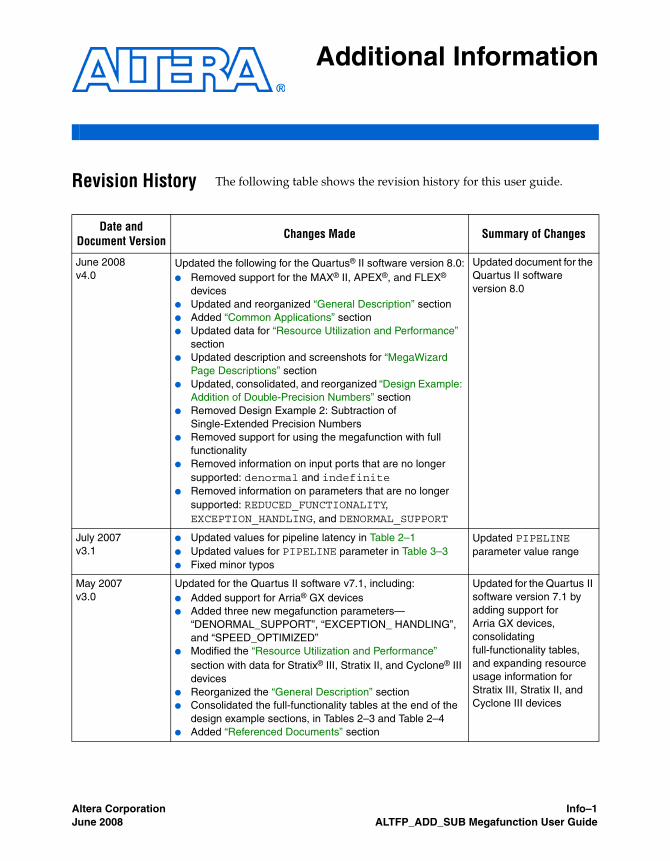
Revision History The following table shows the revision history for this user guide.
Date and Document Version Changes Made Summary of Changes
June 2008v4.0
Updated the following for the Quartus® II software version 8.0:● Removed support for the MAX® II, APEX®, and FLEX®
devices● Updated and reorganized “General Description” section● Added “Common Applications” section● Updated data for “Resource Utilization and Performance”
section● Updated description and screenshots for “MegaWizard
Page Descriptions” section● Updated, consolidated, and reorganized “Design Example:
Addition of Double-Precision Numbers” section● Removed Design Example 2: Subtraction of
Single-Extended Precision Numbers● Removed support for using the megafunction with full
functionality● Removed information on input ports that are no longer
supported: denormal and indefinite● Removed information on parameters that are no longer
supported: REDUCED_FUNCTIONALITY, EXCEPTION_HANDLING, and DENORMAL_SUPPORT
Updated document for the Quartus II software version 8.0
July 2007v3.1
● Updated values for pipeline latency in Table 2–1● Updated values for PIPELINE parameter in Table 3–3● Fixed minor typos
Updated PIPELINE parameter value range
May 2007v3.0
Updated for the Quartus II software v7.1, including:● Added support for Arria® GX devices● Added three new megafunction parameters—
“DENORMAL_SUPPORT”, “EXCEPTION_ HANDLING”, and “SPEED_OPTIMIZED”
● Modified the “Resource Utilization and Performance” section with data for Stratix® III, Stratix II, and Cyclone® III devices
● Reorganized the “General Description” section● Consolidated the full-functionality tables at the end of the
design example sections, in Tables 2–3 and Table 2–4● Added “Referenced Documents” section
Updated for the Quartus II software version 7.1 by adding support for Arria GX devices, consolidating full-functionality tables, and expanding resource usage information for Stratix III, Stratix II, and Cyclone III devices

Info–2 Confidential—Internal Use Only Altera CorporationALTFP_ADD_SUB Megafunction User Guide June 2008
Referenced Documents
Referenced Documents
This user guide references the following documents:
■ Quartus II Integrated Synthesis chapter in volume 1 of the Quartus II Handbook
■ Recommended HDL Coding Styles chapter in volume 1 of the Quartus II Handbook
■ Simulation section in volume 3 of the Quartus II Handbook■ Synthesis section in volume 1 of the Quartus II Handbook
How to Contact Altera
For the most up-to-date information about Altera® products, refer to the following table.
March 2007v2.2
● Added Cyclone III device to list of supported devices● Corrected Figure 2-12
Updated for Quartus II version 7.0 by adding support for Cyclone III device
December 2006v2.1
Added Stratix III device support to Table 1–1 —
June 2006v2.0
Updated for Quartus II 6.0 software release —
May 2005v1.0
Initial release —
Contact (1) Contact Method Address
Technical support Website www.altera.com/mysupport
Technical training Website www.altera.com/training
Email [email protected]
Product literature Website www.altera.com/literature
Non-technical support (General) Email [email protected]
(Software Licensing) Email [email protected]
Note to table:(1) You can also contact your local Altera sales office or sales representative.
Altera Corporation Confidential—Internal Use Only Info–3June 2008 ALTFP_ADD_SUB Megafunction User Guide
Additional Information
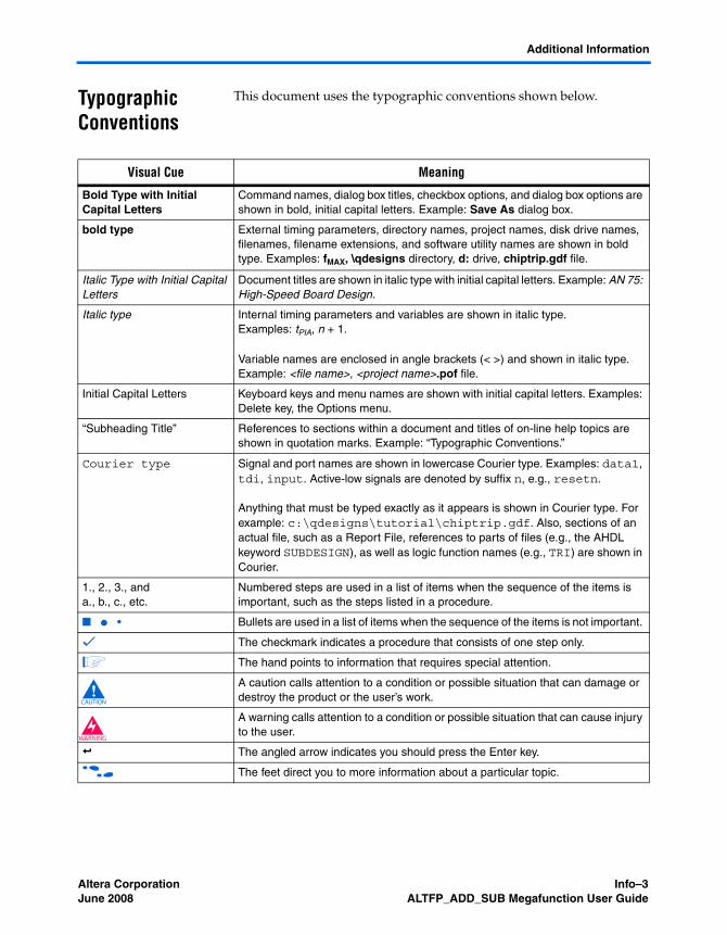
Typographic Conventions
This document uses the typographic conventions shown below.
Visual Cue Meaning
Bold Type with Initial Capital Letters
Command names, dialog box titles, checkbox options, and dialog box options are shown in bold, initial capital letters. Example: Save As dialog box.
bold type External timing parameters, directory names, project names, disk drive names, filenames, filename extensions, and software utility names are shown in bold type. Examples: fMAX, \qdesigns directory, d: drive, chiptrip.gdf file.
Italic Type with Initial Capital Letters
Document titles are shown in italic type with initial capital letters. Example: AN 75: High-Speed Board Design.
Italic type Internal timing parameters and variables are shown in italic type. Examples: tPIA, n + 1.
Variable names are enclosed in angle brackets (< >) and shown in italic type. Example: <file name>, <project name>.pof file.
Initial Capital Letters Keyboard keys and menu names are shown with initial capital letters. Examples: Delete key, the Options menu.
“Subheading Title” References to sections within a document and titles of on-line help topics are shown in quotation marks. Example: “Typographic Conventions.”
Courier type Signal and port names are shown in lowercase Courier type. Examples: data1, tdi, input. Active-low signals are denoted by suffix n, e.g., resetn.
Anything that must be typed exactly as it appears is shown in Courier type. For example: c:\qdesigns\tutorial\chiptrip.gdf. Also, sections of an actual file, such as a Report File, references to parts of files (e.g., the AHDL keyword SUBDESIGN), as well as logic function names (e.g., TRI) are shown in Courier.
1., 2., 3., anda., b., c., etc.
Numbered steps are used in a list of items when the sequence of the items is important, such as the steps listed in a procedure.
■ ● • Bullets are used in a list of items when the sequence of the items is not important.
v The checkmark indicates a procedure that consists of one step only.
1 The hand points to information that requires special attention.
c A caution calls attention to a condition or possible situation that can damage or destroy the product or the user’s work.
w A warning calls attention to a condition or possible situation that can cause injury to the user.
r The angled arrow indicates you should press the Enter key.
f The feet direct you to more information about a particular topic.

Info–4 Confidential—Internal Use Only Altera CorporationALTFP_ADD_SUB Megafunction User Guide June 2008
Typographic Conventions


![Design of a Controllable Adder-Subtractor circuit using ... Issue 4/Version-3... · Serial adder and ripple carry adder is shown [15] using coplanar wire crossing. Half adder and](https://static.fdocuments.us/doc/165x107/5c91648209d3f258468bb62e/design-of-a-controllable-adder-subtractor-circuit-using-issue-4version-3.jpg)