FLM‑420‑I2 Input Interface Modulesresource.boschsecurity.com/documents/FLM_420_I2... · Fire...
4
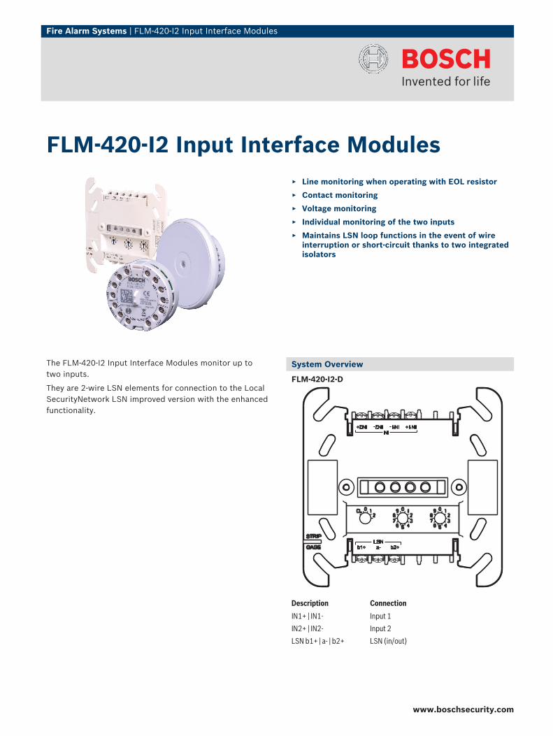
Fire Alarm Systems | FLM‑420‑I2 Input Interface Modules The FLM‑420‑I2 Input Interface Modules monitor up to two inputs. They are 2‑wire LSN elements for connection to the Local SecurityNetwork LSN improved version with the enhanced functionality. System Overview FLM-420-I2-D Description Connection IN1+ | IN1- Input 1 IN2+ | IN2- Input 2 LSN b1+ | a- | b2+ LSN (in/out) FLM‑420‑I2 Input Interface Modules ▶ Line monitoring when operating with EOL resistor ▶ Contact monitoring ▶ Voltage monitoring ▶ Individual monitoring of the two inputs ▶ Maintains LSN loop functions in the event of wire interruption or short-circuit thanks to two integrated isolators www.boschsecurity.com
-
Upload
truongduong -
Category
Documents
-
view
295 -
download
0
Transcript of FLM‑420‑I2 Input Interface Modulesresource.boschsecurity.com/documents/FLM_420_I2... · Fire...
Fire Alarm Systems | FLM‑420‑I2 Input Interface Modules
The FLM‑420‑I2 Input Interface Modules monitor up totwo inputs.
They are 2‑wire LSN elements for connection to the LocalSecurityNetwork LSN improved version with the enhancedfunctionality.
System Overview
FLM-420-I2-D
Description Connection
IN1+ | IN1- Input 1
IN2+ | IN2- Input 2
LSN b1+ | a- | b2+ LSN (in/out)
FLM‑420‑I2 Input Interface Modules Line monitoring when operating with EOL resistor
Contact monitoring
Voltage monitoring
Individual monitoring of the two inputs
Maintains LSN loop functions in the event of wireinterruption or short-circuit thanks to two integratedisolators
www.boschsecurity.com

2 | FLM‑420‑I2 Input Interface Modules
FLM-420-I2-E / FLM-420-I2-W
Description Connection
IN1- | IN1+ Input 1
IN2- | IN2+ Input 2
LSN-SHIELD Shielding cable (if available)
LSN POWER0 V | 0 V | +24 V | +24 V
LSN power supply (supports for loopingthrough)
LSN a1- | b1+ | a2- | b2+ LSN (in/out)
Functions
Monitoring functionsThe FLM‑420‑I2 Input Interface Modules offer threemonitoring functions:
1. Monitoring of a line with EOL resistor2. Monitoring of a potential-free contact3. Voltage monitoringThe monitoring functions can be selected for the twoinputs individually by address setting via the programmingsoftware.
Line monitoring with EOL resistorOperation with EOL resistor can be programmed for eachinput individually. The standard EOL resistor is 3.9 kΩ.
The interface module detects
• Standby• Triggering in the event of line interruption• Triggering in the event of a short circuit.
IN+
IN-
REOL REOL
RL/2
RL/2
IN
Position Description
RΣ Overall line resistance with RΣ = RL/2 + RL/2 + REOL
RL/2 Line resistance
The following line conditions will be definitely detected ifthe overall line resistance is within the specified ranges:
Line condition Overall line resistance RΣ
Standby 1500 Ω to 6000 Ω
Interruption > 12.000 Ω
Short circuit < 800 Ω
Contact monitoring
IN+
IN-RL/2
RL/2IN
Position Description
RL/2 Line resistance with RL/2 + RL/2 ≤ 50 Ω
The interface module evaluates the operating conditions"open" or "closed". The normal operating condition can beprogrammed for each input. Contact monitoring is carriedout with a pulse intensity of 8 mA. The module detectssignals from a duration of 300 ms.
Voltage monitoring
V
RL/2
RL/2IN
IN+
IN-
Position Description
RL/2 Line resistance with RL/2 + RL/2 ≤ 50 Ω
Voltage monitoring is carried out between 0 V DC and30 V DC. The programming software can be used to selecttwo threshold values.
Address switchesThe addresses of the interface modules are set using:
• DIP switches for FLM‑420‑I2‑E and FLM‑420‑I2‑W• Rotary switches for FLM‑420‑I2‑D.In improved version LSN mode, the operator can selectautomatic or manual addressing with or without auto-detection.

FLM‑420‑I2 Input Interface Modules | 3
Addressrotary
switches
AddressDIP switches
Operating mode
0 0 0 0 Loop/stub in improved version LSN modewith automatic addressing (T-taps notpossible)
0 0 1-
2 5 4
1 – 254 Loop/stub/T-taps in improved versionLSN mode with manual addressing
CL 0 0 255 Loop/stub in LSN mode classic
LSN featuresIntegrated isolators ensure that function is maintained inthe event of a short circuit or line interruption in the LSNloop. A fault indication is sent to the fire panel.
Features of LSN improved versionThe interface modules in the 420 series offer all thefeatures of improved LSN technology:
• Flexible network structures including T‑tappingwithout additional elements
• Up to 254 LSN-improved elements per loop or stubline
• Unshielded cable can be used
Interface variantsThe Input Interface Modules are available in variousdesigns:
• FLM‑420‑I2‑E type in-built:- Can be built in to standard device boxes in
accordance with EN 60670 (e.g. below standardswitch programs)
- For space-saving installation in devices• FLM‑420‑I2‑W type wall-mount (with cover):
- Can be built in to standard device boxes inaccordance with EN 60670
- For surface mounting in conjunction with theFMX‑IFB55‑S interface box.
• FLM‑420‑I2‑D type DIN rail:- For installation on a DIN rail in accordance with
EN 60715 with included adapter- Can be built in to a FLM‑IFB126‑S surface-
mounted housing.
Certifications and Approvals
Complies with
• EN54-17:2005• EN54-18:2005
Region Certification
Germany VdS G 207076 FLM-420-I2-D; FLM-420-I2-E; FLM-420-I2-W
Europe CE FLM-420-I2-W/-E
FLM-420-I2-D
CPD 0786-CPD-20288 FLM-420-I2-D
0786-CPD-20287 FLM-420-I2-W, -E
MOE UA1.016-0070269-11 FLM-420-I2-W_FLM-420-I2-E_FLM-420-I2-D
Installation/Configuration Notes
• Can be connected to the fire panels FPA‑5000 andFPA‑1200.
• Programming is done with the programming softwareof the fire panel.
• The LSN connection is established via the two wireson the LSN line.
• A maximum cable length of 3 m is permitted per input.• When mounting the in-built type interface module
below a switch, a minimum depth of the device box of60 mm is recommended.
• The in-built (-E) and wall-mount (-W) versions arefitted with terminals to allow a second wire pair to belooped through to the LSN power supply ofsubsequent elements.
Parts Included
Type Qty. Component
FLM-420-I2-E 1 Input Interface Module, type in-built
FLM-420-I2-W 1 Input Interface Module, type wall-mount,with cover and accessories
FLM-420-I2-D 1 Input Interface Module, type DIN rail, withadapter and light pipe
Technical Specifications
Electrical
LSN
• LSN input voltage 15 V DC to 33 V DC
• Max. current consumptionfrom LSN
10.4 mA
Inputs 2, independent of each other
Line monitoring with EOL
• EOL resistor Nominal 3.9 kΩ
• Overall line resistance • During standby: 1500 to6000 Ω
• Interruption: > 12.000 Ω• Short circuit: < 800 Ω
www.boschsecurity.com
4 | FLM‑420‑I2 Input Interface Modules
Contact monitoring
• Max. current (current peak) 8 mA
Voltage monitoring
• Voltage range 0 to 30 V DC
• Input resistance ≥ 50 kΩ
• Selectable threshold values • 0.8 V DC (± 0.3 V DC)• 3.3 V DC (± 0.3 V DC)• 10.2 V DC (± 0.5 V DC)• 21.2 V DC (± 0.5 V DC)
Mechanical
Connections
• FLM-420-I2-E / W 14 screw terminals
• FLM-420-I2-D 7 screw terminals
Permitted wire cross-section
• FLM-420-I2-E / W 0.6 to 2.0 mm2
• FLM-420-I2-D 0.6 to 3.3 mm2
Address setting
• FLM-420-I2-E / W 8 DIP switches
• FLM-420-I2-D 3 rotary switches
Housing material
• FLM-420-I2-E / W ABS/PC blend
• FLM-420-I2-D with adapt-er
PPO (Noryl)
Color
• FLM-420-I2-E / W Signal white, RAL 9003
• FLM-420-I2-D with adapt-er
Off-white, similar to RAL 9002
Dimensions
• FLM-420-I2-E Approx. 50 mm x 22 mm (Ø x H)
• FLM-420-I2-W Approx. 76 mm x 30 mm (Ø x H)
• FLM-420-I2-D with adapt-er
Approx. 110 x 110 x 48 mm(W x H x D)
Weight Without / with packaging
• FLM-420-I2-E Approx. 35 g / 130 g
• FLM-420-I2-W Approx. 55 g / 155 g
• FLM-420-I2-D Approx. 150 g / 235 g
Environmental conditions
Permitted operating temperature -20 °C to +65 °C
Permitted storage temperature -25 °C to +80 °C
Permitted rel. humidity < 96% (non-condensing)
Classes of equipment as perIEC 60950
Class III equipment
Protection class as per IEC 60529 IP 30
System limiting values
Max. cable length per input 3 m
Ordering Information
FLM‑420‑I2‑E Input Interface Modulewith 2 monitored inputs, flush-mount type
FLM-420-I2-E
FLM‑420‑I2‑W Input Interface Modulewith 2 monitored inputs, wall-mount type,with cover
FLM-420-I2-W
FLM‑420‑I2‑D Input Interface Modulewith 2 monitored inputs, DIN rail type
FLM-420-I2-D
Accessories
FLM‑IFB126‑S Surface-mounted Housingas retainer for the interface modules ser-ies 420 type DIN rail (-D) or spare housing fortype surface-mount (-S)
FLM-IFB126-S
FMX‑IFB55‑S Interface Box Surface-mountfor interface modules of wall mount type inthe 420 series, surface-mount
FMX-IFB55-S
Americas:Bosch Security Systems, Inc.130 Perinton ParkwayFairport, New York, 14450, USAPhone: +1 800 289 0096Fax: +1 585 223 [email protected]
Europe, Middle East, Africa:Bosch Security Systems B.V.P.O. Box 800025600 JB Eindhoven, The NetherlandsPhone: + 31 40 2577 284Fax: +31 40 2577 [email protected]
Asia-Pacific:Robert Bosch (SEA) Pte Ltd, Security Systems11 Bishan Street 21Singapore 573943Phone: +65 6258 5511Fax: +65 6571 [email protected]
Represented by
© Bosch Security Systems 2011 | Data subject to change without noticeT3271741579 | Cur: en-US, V27, 18 Jul 2011 | Src: en-US, V0, 12 Apr 2006