FLEXWELL® Safety · PDF file26.01.2015 – P – page 3 Subject to technical...
28
FLEXWELL® Safety Pipe Pipe system for installations Project planning
Transcript of FLEXWELL® Safety · PDF file26.01.2015 – P – page 3 Subject to technical...

FLEXWELL® Safety Pipe
Pipe system for installations
Project planning

26.01.2015 – P – page 2
FLEXWELL® Safety Pipe – Project planning FSR
Subject to technical changes.
Contents
Processing enquiries
Minutes of the hearing to award the contract/giving the order
Datasheet FLEXWELL® Safety Pipe
Resistance of materials
Basic planning parameters4.320 General information 4.321 Planning the routing 4.322 Determining the pipe lengths involved4.323 Details for excavation work
Fluid engineering4.330 Pressure loss diagramme for Regular and Super (4 star) Petrol 4.331 Pressure loss diagramme for Heating oil (EL) and Diesel fuel 4.332 Pressure loss diagramme for Liquid propane 4.333 Pressure loss diagramme for gaseous propane
Laying4.300 Wall through-connections Type MD 4.301 Wall breakthroughs, Core holes 4.302 Steel manhole and pipe sleeve openings 4.303 Annular space seal for core hole or fibre cement casing 4.304 Fire prevention through-connection, bulkheading 4.307 Anchor fittings to buildings, pipe bridges etc.
Texts for invitations to tenderWordings of invitations to tender for FLEXWELL® Safety Pipe are available on request.

26.01.2015 – P – page 3Subject to technical changes.
Pipe systems for installations/petrol stations – Project planning
Processing enquiries
Customer/Contractual partner:
Company: ___________________________________
Country: ___________________________________
Contact person: ___________________________________
eMail address: ___________________________________
Desired
date of offer: ___________________________________
Project details:
Project designation: ______________________________
Postcode / Town: ______________________________
estimated project value (PW): ____________________________ T€
Chance of getting order (AC): ____________________________ %
Desired probable exec. date: ______________________________
Competitors: ______________________________
Product group: Market segment:
FLEXWELL® Safety Pipe ______________________________
BRUGG-STAMANT® ______________________________
SECON-X® ______________________________
FLEXWELL-LPG® ______________________________
NIROFLEX® ______________________________
SPIRAFLEX® ______________________________
Training seminars ______________________________
Other ______________________________
Length: m _________________________________
Dimensions: DN _________________________________
Layout: for SECON-X® petrol station required
Routing: for BRUGG-STAMANT® absolutely necessary
Principle sketch: in other cases
Description of work German
to be done: English
Description of project: _____________________________________________________
_____________________________________________________
_____________________________________________________
_____________________________________________________
Date/Signature:
__________________________________
Date/Signature:
__________________________________
Fire prevention:
Wall/ceiling thickness: _________________________________
Information on medium for FLEXWELL® Safety Pipe, BRUGG-STAMANT® Safety Pipe,
SECON-X® or FLEXWELL-LPG®:
Substance to be carried: ___________________________________
Data for supply: Supply rate Supply pressure Temperature
______ m3/h ______ bar ______ °C
Data for laying: In the ground Empty pipe Canal
Building Pipe bridge Other
Received by BRUGG:
_______________________________
_______________________________
Customer BRUGG: _____________________________________________________
Project BRUGG: _____________________________________________________
_____________________________ _____________________________
_____________________________ _____________________________
________________________________ ________________________________
_____________________________ _____________________________
________________________________ ________________________________To b
e fil
led
out b
y BR
UGG
Roh
rsys
tem
eBy eMail to: [email protected]
By fax to: +49 (0)5031 170-189

26.01.2015 – P – page 4Subject to technical changes.
Pipe systems for installations/petrol stations – Project planning
Notes

26.01.2015 – P – page 5
FLEXWELL® Safety Pipe – Project planning FSR
Subject to technical changes.
4.001
Minutes of the hearing to award the contract/order
ClientDate/Initials
ContractorDate/Initials
Client (AG)
Company: _____________________________________________________
Street/Postbox: _____________________________________________________
Postcode Town: _____________________________________________________
Telephone: _____________________________________________________
eMail: _____________________________________________________
Person spoken to/ _____________________________________________________
Function: _____________________________________________________
Contractor (AN)
BRUGG Rohrsysteme GmbH
Adolf-Oesterheld-Straße 31
31515 Wunstorf
Person spoken to/Function:
___________________________________
___________________________________
Project ________________________________________________________________________________________
Address of construction site: ________________________________________________________________________________________
The following was agreed upon
1. The following documents/agreements shall apply ________________________________________________________________________
and Conditions/Basis for discussions: ________________________________________________________________________
Offer(s), No./Date ________________________________________________________________________
Products ________________________________________________________________________
Technical remarks in advance/approvals ________________________________________________________________________
Existing “confirmed” drawings ________________________________________________________________________
Supplementary agreements: ________________________________________________________________________
________________________________________________________________________
________________________________________________________________________
2. Scope of work: ________________________________________________________________________
Offer No./Date ________________________________________________________________________
Contract specifications pages, items ________________________________________________________________________
Delivery, laying ________________________________________________________________________
Insulation after installation ________________________________________________________________________
3. Additional work to be done: ________________________________________________________________________
Addendum, if known ________________________________________________________________________
Services to be performed ________________________________________________________________________
(details of pricing/remuneration)

26.01.2015 – P – page 6
FLEXWELL® Safety Pipe – Project planning FSR
Subject to technical changes.
4.002
Minutes of the hearing to award the contract/order
ClientDate/Initials
ContractorDate/Initials
4. Drawings and other technical documents ____________________________________________________________________
(e.g. offer, contract specifications, ____________________________________________________________________
construction schedule, handover date): ____________________________________________________________________
Routing to be fixed by (person): ____________________________________________________________________
Routing plans to be provided by (person)/by (date): ____________________________________________________________________
To be checked /confirmed by (person)/by (date): ____________________________________________________________________
5. Certificates and other documentation: ____________________________________________________________________
____________________________________________________________________
____________________________________________________________________
6. Dates: ____________________________________________________________________
Drawings and other ____________________________________________________________________
Technical documentation ____________________________________________________________________
Deliveries ____________________________________________________________________
Start of installation work ____________________________________________________________________
Completion of installation work ____________________________________________________________________
Interim deadlines ____________________________________________________________________
7. Time overruns: ____________________________________________________________________
8. Price(s): as per offer(s) No./Date ____________________________________________________________________
Contract specifications pages, items ____________________________________________________________________
Valid until ____________________________________________________________________
____________________________________________________________________
9. Payment terms: ____________________________________________________________________
Net of deductions, trade discount ____________________________________________________________________
Payment terms ____________________________________________________________________
Payments on account for deliveries of material ____________________________________________________________________
Payments on account for installation work ____________________________________________________________________
26.01.2015 – P – page 7
FLEXWELL® Safety Pipe – Project planning FSR
Subject to technical changes.
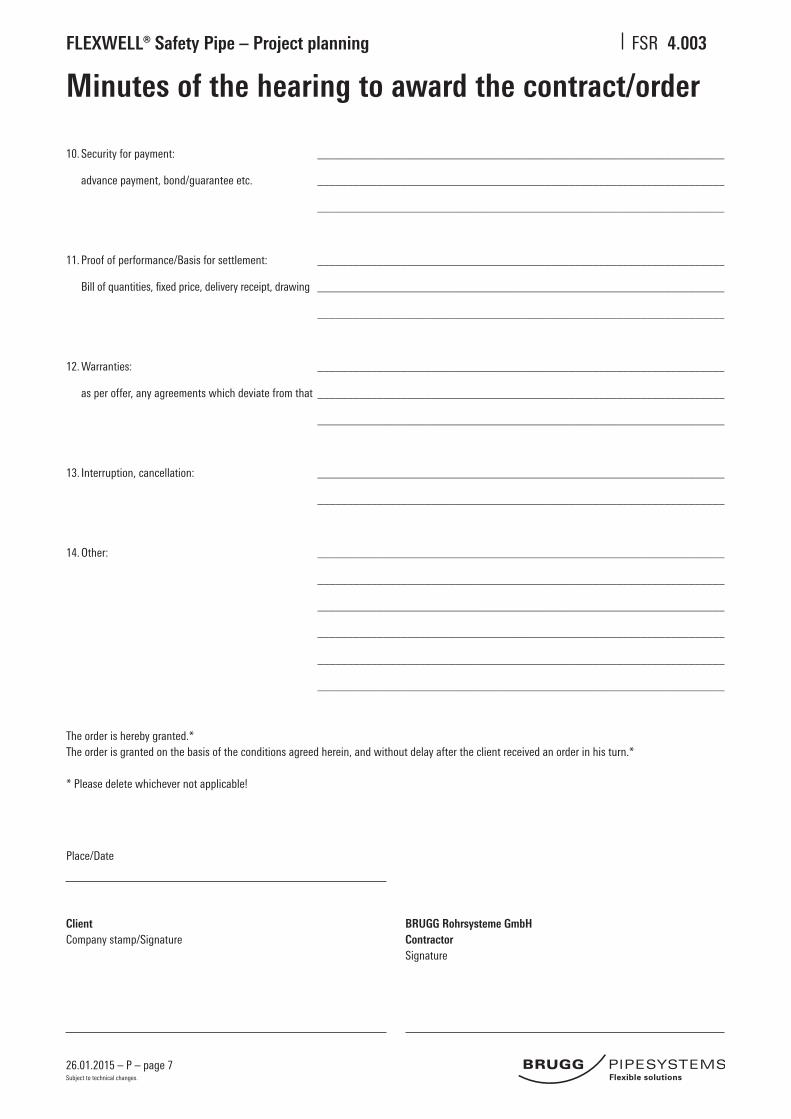
4.003
Minutes of the hearing to award the contract/order
ClientCompany stamp/Signature
BRUGG Rohrsysteme GmbHContractorSignature
10. Security for payment: ____________________________________________________________________
advance payment, bond/guarantee etc. ____________________________________________________________________
____________________________________________________________________
11. Proof of performance/Basis for settlement: ____________________________________________________________________
Bill of quantities, fixed price, delivery receipt, drawing ____________________________________________________________________
____________________________________________________________________
12. Warranties: ____________________________________________________________________
as per offer, any agreements which deviate from that ____________________________________________________________________
____________________________________________________________________
13. Interruption, cancellation: ____________________________________________________________________
____________________________________________________________________
14. Other: ____________________________________________________________________
____________________________________________________________________
____________________________________________________________________
____________________________________________________________________
____________________________________________________________________
____________________________________________________________________
The order is hereby granted.* The order is granted on the basis of the conditions agreed herein, and without delay after the client received an order in his turn.*
* Please delete whichever not applicable!
Place/Date

26.01.2015 – P – page 8
FLEXWELL® Safety Pipe – Project planning FSR
Subject to technical changes.
Notes

26.01.2015 – P – page 9Subject to technical changes.
Flexible, double-walled pipe system with stainless steel inner pipe and outer containment pipe and permanent leak detection with approval Z-38.4-253
System descriptionFLEXWELL® Safety Pipe was specially designed for the underground transport of flammable, water-hazardous fluids. It can be used as a suction or positive pressure supply pipe. The FLEXWELL® Safety Pipe can be permanently monitored by means of suitable leak detectors.
ConstructionFLEXWELL® Safety Pipe is a flexible, permanently monitorable, double-walled pipe system. The FLEXWELL® Safety Pipe consists of a corrugated stainless steel inner medium pipe, a spacer tape and a cor-rugated outer containment pipe made of stainless steel. The annular gap between the inner and outer pipes is a surveillance space for leak monitoring. External corrosion protection is provided by a PE casing covering the outer pipe. Range of Applications• suction pipe• positive pressure supply pipe• filling pipe
Nominal bores / pressure stagesFLEXWELL® Safety Pipe is available in nominal bores from DN 12 to DN 100. It can be operated with positive pressure up to max. 25 bar.
Laying the pipesFLEXWELL® Safety Pipe can be laid directly into the trench in one piece. It can be laid either overground in a trace or inside of bulidings. The unique corrugated pipe geometry of inner medium pipe and outer containment pipe ensures excellent flexibility. It can be cut to the re-quired length at the construction site, laid endlessly and bent through tight radii thanks to its flexibility.
FLEXWELL® Safety Pipe Pipe system for installations
Double-walled fittingsMonitorable through-connections and T-pieces as well as connectors with measuring branches are all part of the comprehensive range of products available in the FLEXWELL Safety Pipe programme.
Leak monitoringThe surveillance space between the inner and outer pipes can be per-manently monitored by means of suitable positive or negative pressure leak detectors. A wide range of leak detection systems for different areas of application and legal requirements is available.

26.01.2015 – P – page 10Subject to technical changes.
BRUGG Rohrsysteme GmbH
Adolf-Oesterheld-Straße 31
D-31515 Wunstorf
phone +49 (0)50 31 170-0
fax +49 (0)50 31 170-170
www.brugg.de
Brugg Rohrsystem AG
Industriestrasse 39
CH-5314 Kleindöttingen
phone +41 (0)56 268 78 78
fax +41 (0)56 268 78 79
www.pipesystems.com
A company of the BRUGG Group
Material: • inner pipe 1.4404/1.4571 • outer pipe 1.4301 • armouring steel • corrosion proofing PE-LD casingOperating pressure inner pipe: • vacuum suction pipe up to – 0.8 bar • positive pressure up to 25 barMonitoring pressure outer pipe, • vacuum – 0.7 barpermanent • positive pressure up to 25 bar (dependent of operating pressure)
Technical data FLEXWELL® Safety Pipe
Subject to technical alterations
FLEXWELL® Safety Pipe Positive pressure leak detector
1 corrugated inner medium pipe of stainless steel2 corrugated outer containment pipe of stainless steel3 polyethylene casing
1 leak detector2 pressure reservoir3 double-walled corrugated FLEXWELL® Safety Pipe with measuring branch and test valve4 distributor
3
2
1
3
2
1
4
Type Nominal bore inner outer volume weight bending DN diameter diameter inner pipe radius mm mm l/m kg/m cm FSR 13/ 25 12 13 25 0.13 0.52 30 FSR 30/ 48 25 30 48 0.80 1.40 50 FSR 39/ 60 32 39 60 1.30 2.00 60 FSR 48/ 71 40 48 71 2.00 2.90 60 FSR 60/ 83 50 60 83 3.00 3.80 70 FSR 75/107 65 75 107 5.10 6.20 90 FSR 98/134 80 98 134 8.40 9.00 120 FSR 127/175 100 127 175 14.00 18.10 150
Dimensions
04 /
13 /
xxx
ex. /
846
8000
8

26.01.2015 – P – page 11
FLEXWELL® Safety Pipe – Project planning FSR
Subject to technical changes.
Resistance of material
The resistances for Materials No. 1.4404 for the inner pipe and 1.4301 for the outer pipe against various fluids acc. to DIN 6601 are confirmed as regards the following selection of transport media:
Petrol DIN EN 228
Petroleum spirit DIN 51632 – 1Petroleum spirit DIN 51632 – 2Petroleum spirit DIN 51632 – 3Petroleum spirit DIN 51632 – 4, auto ignition temperature > 55 °C, auto ignition temperature > 61 °C
Diesel fuels DIN EN 590Diesel fuels, 61 < auto ignition temperature ≤ 100 °CDiesel fuels, auto ignition temperature ≤ 61 °CBiodiesel
AdBlue – carbamide, diluted
Kerosine, 21 ≤ auto ignition temperature ≤ 55 °C
Heating oil, light, 61 < auto ignition temperature ≤ 100 °CHeating oil, light, auto ignition temperature as per EN 590Heating oil DIN 51603
Hydraulic fluid DIN 51502 – HFCHydraulic fluid DIN 51502 – HFD-R Hydraulic fluid DIN 51502 – HFC-THydraulic oil DIN 51524Hydraulic oil DIN 51524
Refrigerating maschine oil DIN 51503
Motor oil SAE
Oils DIN 51502 – FOils DIN 51502 – JOils DIN 51502 – R
Lubricating oils DIN 51501Lubricating oils DIN 51502Lubricating oils DIN 51506Lubricating oils DIN 51510Lubricating oils DIN 51513Lubricating oils DIN 51515Lubricating oils DIN 51517 MethanolMethanol, dilutedEthanolEthanol in acqueous solution Bioethanol Isopropanol
Diethylene glycol/Glycol
Caustic soda solution up to max. 50 % NaOH
Ammoniac Diluted ammoniac, 0.88 ≤ concentration ≤ 0.957at 15 °C in water, 10 up to 35 %
Toluene
Certification of resistances for further fluids
The resistance of the pipe material for the medium-carrying pipes must be certified acc. to DIN 6601 (Positive Fluid list) or as a qualified individual test certificate.
Please note!
The properties of particular transport media must be considered for each project.

26.01.2015 – P – page 12
FLEXWELL® Safety Pipe – Project planning FSR
Subject to technical changes.
4.320
Basic planning parameters
In contrast to conventional piping, FLEXWELL® Safety Pipe is a flexible pipe system. It is manufactured in our works in endless lengths and wound onto cable drums. Due to its flexibility FLEXWELL® Safety Pipe can be laid in one piece over long stretches of the routing without any need for moulded parts. Installation work to assemble and fit pipe connections and to insulate the piping on site is only necessary at the ends of the pipe sections.
Delivery lengths Type DN Delivery lengths
on a druml as a coil
m m
FSR 13/ 25 12 500 500
FSR 30/ 48 25 750 525
FSR 39/ 60 32 650 415
FSR 48/ 71 40 550 255
FSR 60/ 83 50 500 200
FSR 75/107 65 400 125
FSR 98/134 80 400 90
FSR 127/175 100 350 50
Expansion takeup
Longitudinal expansion as a result of thermal influences is compensated in FLEXWELL® Safety Pipe rather like an expan-sion joint by the geometrical change in the corrugation of the pipes. That is why no action needs to be taken to compen-sate for expansion when using FLEXWELL® Safety Pipes. Expansion bends such as those needed on conventional piping can be dispensed with.
Anchor points
Anchor points are not necessary when the pipe is laid underground. In this case, the routing can be chosen completely freely and causes no extra work. Increase in the volume of fluids due to thermal influences and concomitant pressure increases can be compensated to a limited extent in surface laying.
Safety precautions
The following technical principles apply to FLEXWELL® Safety Pipe, and correspond to best engineering practice:- Piping must be equipped with all devices needed for safe operations. - Piping must be secured against exceeding the permissible pressures where it is cannot be excluded that such
pressures may be exceeded. - The safety equipment to prevent exceeding of permissible pressure must be installed in an appropriate position. - For instance, spill valves are a suitable means of preventing pressure increases exceeding the permissible level as a
result of temperature increases in flammable fluids e.g. due to exposure to sunshine. - Unenclosed piping must be tightly sealed against fluid loss. - Surface routed piping which is directly exposed to the sun must be shielded from sunshine using appropriate means.
Screws and seals
Screws and seals are not included in the scope of delivery.
IMPORTANT! Only use steel screws of strength class 4.6, 5.6 or 8.8. Screws of strength class ≥ 10.9 may not be used. When stainless steel screws are used, the area underneath the heads and on the thread must be lubricated with copper paste. This is absolutely necessary for the friction coefficient and maximum tightening torque. Only stainless steel screws with maximum strength class A 70 may be used.
Installation instruction for split loose flangeThe splitting of the loose flange needs to be installed staggered 90° in reverse order.
General information
Longer pipe lengths are connected on site with monitorable through-connections.

26.01.2015 – P – page 13
FLEXWELL® Safety Pipe – Project planning FSR
Subject to technical changes.
4.321
Basic planning parameters
Routing with branching off pipes
Where a number of differently located users need to be supplied by piping, this is normally done with conventional piping by laying feeder lines branching off from the main line. This makes it necessary to install T-branches, creating extra work on site. In the case of underground piping this also creates an extra risk, since the branches can neither be seen nor easily checked for leaks.
The flexibility of FLEXWELL® Safety Pipe allows it to be laid according to the “looping in” method familiar from high-voltage power cables (see the diagramme).
„Looping in“ means:1. The actual branching-off pipe, illustrated as a bridgeover, lies in an area where it is protected or easy to check (e.g. in
a manhole pit or the boiler room.)2. There is no connection to be installed by hand in the ground. This means that the corrosion-proofing fitted during
manufacture in our factory is at no point interrupted in the underground routing.
Corrosion-proofed and completely monitorable T-branches can be delivered for special cases. We would like to point out however that “looping in” is normally much more economical than fitting monitorable T-branches.
Pipe gradient, existing supply lines, stray currents
It makes a lot of sense to lay FLEXWELL® Safety Pipe with the gradients normally used in piping construction in order to be able to easily evacuate and vent the pipes or systems. In heavily built-up areas it is often the case, however, that already existing supply lines cross the planned routing. As long as no minimum distances between lines are stipulated by law or by the owners, FLEXWELL® Safety Pipe can simply be “threaded” through the crossing lines or led around other obstacles (see the diagramme). This only applies to positive pressure lines however. In the case of suction pipes, upward “jumps” greater than the internal diameter of the inner pipe are not permissible.
The rules of good engineering practice for pipelaying must be observed in all cases. In particular the properties of the transport media must be taken into consideration.
FLEXWELL® Safety Pipe is protected from stray currents due to its uninterrupted PE casing. This is proved by a 20 kV high voltage test in factory. In the vicinity of direct-current installations (tramlines, cathodically protected piping) it can be laid without there being any disadvantages to any part of the installation expected.
AUser
B CFLEXWELL® Safety Pipe looped in,
no branches underground
Main supply line with branching feeder lines
and T-branches as used in conventional piping
The looping in method
Routing around underground obstacles
Routing

26.01.2015 – P – page 14
FLEXWELL® Safety Pipe – Project planning FSR
Subject to technical changes.
4.322
Basic planning parameters
Example of a routing sketch with determination of the lengths for FSR 39/60
Table 1 Determining the lengths
Type for a for a 90° elbow
Bending radius R* von deduct from value lx
FSR 13/ 25 0.3 m lx = – 0.12 m
FSR 30/ 48 0.5 m lx = – 0.21 m
FSR 39/ 60 0.6 m lx = – 0.25 m
FSR 48/ 71 0.6 m lx = – 0.25 m
FSR 60/ 83 0.7 m lx = – 0.30 m
FSR 75/107 0.9 m lx = – 0.39 m
FSR 98/134 1.2 m lx = – 0.52 m
FSR 127/175 1.5 m lx = – 0.64 m
Section Length
l1** 0.20 m
l2 0.40 m
l3 9.30 m
l4 12.80 m
l5 11.70 m
l6 0.15 m
l7* 0.20 m
– lx for 2 x R = 0.6 m – (2 x 0.25 m) = – 0.50 m
Overall length 34.25 m
** Protruding length:Wall duct Worksheet FSR 4.300Steel duct entries Worksheet FSR 4.302R
R
l3l2l1
l5
l6 l7
l4
Refe
renc
e si
ze
* Minimum bending radius R min. – generally done using a me-chanical bending device.
Determining the lengths

26.01.2015 – P – page 15
FLEXWELL® Safety Pipe – Project planning FSR
Subject to technical changes.
4.323
** Protruding length:Wall duct Worksheet FSR 4.300Steel duct entries Worksheet FSR 4.302
Technical regulations and DIN Standards
When carrying out underground work for FLEXWELL® Safety Pipe the following DIN standards, regulations, provisions and guidelines must be observed:
DIN 1072 Straßen- und Wegbrücken, LastannahmenDIN 4124 Baugruben und -gräben; Böschungen, Verbau, ArbeitsraumbreitenDIN 18300 VOB, Teil C, Allgemeine technische Vorschriften; ErdarbeitenDIN 18303 VOB, Teil C, Allgemeine technische Vorschriften; VerbauarbeitenDIN 18307 VOB, Teil C, Allgemeine technische Vorschriften; Druckrohrleitungsarbeiten außerhalb von GebäudenDIN 18320 VOB, Teil C, Allgemeine technische Vorschriften; LandschaftsbauarbeitenDIN 18330 VOB, Teil C, Allgemeine technische Vorschriften; MauerarbeitenDIN 18195 BauwerksabdichtungenDIN 18354 VOB, Teil C, Allgemeine technische Vorschriften; AsphaltbelagarbeitenDIN EN 1610 Entwässerungskanäle und Leitungen, Richtlinie für die Ausführung
Merkheft „Sicherung von Leitungsgräben und Baugruben“, Berufsgenossenschaft der BauwirtschaftMerkblatt über das Zufüllen von Leitungsgräben, Forschungsgesellschaft für das Straßenwesen e.V., Arbeitsgruppe UntergrundAccident pevention regulations and general regulations of the Employers’ Liability Insurance associations (Berufsgenossenschaften)
The gradients normally used in pipeline constructions must be observed when digging the pipe trench.
* When pulling the pipe into the trench, it is not permissible to go below these radii. Minimum bending radius see Works-heet FSR 4.322.
Pipe trench
FLEXWELL® Safety Pipe should be laid on top of a sand bedding at least 10 cm deep (grit size ≤ 2 mm) and covered over according to the rules of TrbF 50 Point 5.4.3 (2) with the same sand. The standards and regulation given below must be observed.
Type FSR laying radii trench depth trench width trench width spoil Sand filling
R* T B1 B2
m m m m m3/lfd. m m3/lfd. m
13/ 25 0.7 0.95 0.30 (0.40) 0.67 (0.73) 0.46 (0.54) 0.09 (0.11)
30/ 48 0.7 0.95 0.30 (0.40) 0.67 (0.73) 0.46 (0.54) 0.09 (0.11)
39/ 60 1.0 1.00 0.30 (0.40) 0.70 (0.75) 0.50 (0.58) 0.10 (0.14)
48/ 71 1.2 1.00 0.30 (0.40) 0.70 (0.75) 0.50 (0.58) 0.10 (0.14)
60/ 83 1.5 1.00 0.30 (0.40) 0.70 (0.75) 0.50 (0.58) 0.10 (0.14)
75/107 1.8 1.05 0.30 (0.40) 0.70 (0.75) 0.53 (0.60) 0.11 (0.15)
98/134 2.0 1.05 0.30 (0.40) 0.70 (0.75) 0.53 (0.60) 0.12 (0.16)
127/175 3.0 1.10 0.40 (0.50) 0.80 (0.90) 0.66 (0.77) 0.17 (0.22)
The routing tape is delivered by BRUGG and must be laid on site.
B2 B2
0.3 m
0.15 m
0.1 - 0.15 m
B1 B1
Sand bedding Sand bedding
FLEXWELL® Safety Pipe
Routing tape
T
Basic planning parametersDetails for underground work

26.01.2015 – P – page 16
FLEXWELL® Safety Pipe – Project planning FSR
Subject to technical changes.
4.330
Fluid engineeringPressure loss diagramme for petrol regular and super (4 star)
Temperature: 15 °CSpecific weight: 735 kg/m3
Kinematic viscosity: 5.5 · 10–7 m2/s
Flow
vol
ume
[l/m
in]
Example:
Pipe DN 50With a flow volume of 80 l/min at a speed of c. 0.4 m/s the pressure loss is 0.6 mbar/m
➤
DN 100
DN 80
DN 65
DN 50
DN 40
DN 32
DN 25
DN 12
Pressure loss
1 10 100 1000 10000
Pa/m
0.1 1 10 100 1000
mmWS/m
0.01 0.1 1 10 100
mbar/m

26.01.2015 – P – page 17
FLEXWELL® Safety Pipe – Project planning FSR
Subject to technical changes.
4.331
Fluid engineeringPressure loss diagramme for heating oil (EL) and diesel fuel
Temperature: 15 °CSpecific weight: 860 kg/m3
Kinematic viscosity: 7 · 10–6 m2/s
Flow
vol
ume
[kg/
h]
Example:
Pipe DN 50With a flow volume of 7000 kg/h at a speed of c. 0.8 m/s the pressure loss is 2.5 mbar/m
➤
DN 100
DN 80
DN 65
DN 50
DN 40
DN 32
DN 25
DN 12
2,5
Pressure loss
10 100 1000 10000
Pa/m
1 10 100 1000
mmWS/m
0.1 1 10 100
mbar/m

26.01.2015 – P – page 18
FLEXWELL® Safety Pipe – Project planning FSR
Subject to technical changes.
4.332
Fluid engineeringPressure loss diagramme for liquid propane
Temperature: 15 °CSpecific weight: 508 kg/m3
Kinematic viscosity: 2.1 · 10–7 m2/s
Flow
vol
ume
[kg/
h]
Example:
Pipe DN 50With a flow volume of 3000 kg/h at a speed of c. 0.5 m/s the pressure loss is 0.8 mbar/m
DN 80
DN 50
DN 100
DN 40
DN 32
DN 25
➤
Pressure loss
1 10 100 1000 10000
Pa/m
0.1 1 10 100 1000
mmWS/m
0.01 0.1 1 10 100
mbar/m
DN 65
DN 12
v = 2 m/s
1,0
0,5

26.01.2015 – P – page 19
FLEXWELL® Safety Pipe – Project planning FSR
Subject to technical changes.
4.333
Fluid engineeringPressure loss diagramme for gaseous propane
Temperature: 15 °CSpecific weight: 8 kg/m3 (3 bar)Dynamic viscosity: 7.9 · 10–6 Ns/m2 = 7.9 · 10–6 kg/ms
Example:
Pipe DN 32With a flow volume of 30 kg/h at a speed of c. 0.9 m/s the pressure loss is 5.6 · 10–2 mbar/m = 5.6 · 10–2 hPa/m
Pressure loss
Flow
vol
ume
[kg/
h]➤
2 3 4 5 6 7 8 2 3 4 5 6 7 8 2 3 4 5 6 7 8 2 3 4 5 6 7 8
0.1 1 10 100 1000
Pa/m
0.01 0.1 1 10 100
mWS/m
0.001 0.01 0.1 1 10
mbar/m = hPa/m
DN 100
DN 80
DN 65
DN 50
DN 40
DN 32
DN 25
DN 20
DN 12
4 m/s
2 m/s
1 m/s0.5 m/s
1000
100
10
1
0.1
86543
2
86543
2
86543
2
8654
2

26.01.2015 – P – page 20
FLEXWELL® Safety Pipe – Project planning FSR
Subject to technical changes.
4.300
Wall duct Type MD
General information
FLEXWELL® Safety Pipe wall duct Type MD must be cemented in on site. If the intallation is correctly executed, the tightness between the concre-te and the through-connection and between the through-connection and the FLEXWELL® Safety Pipe is 0.2 bar.
Wall duct Type MD for FSR 13/25 - FSR 60/83The seal consists of a cross-linked polyolefin shrink sleeve, supported from within by a galvanized steel helix. When the two ends of this are heated using a gas flame they shrink, causing the sealing compound to melt and pressing it into any grooves or unevennesses of the surface.
Type MD L A B max* KD D1 Article No.
mm mm mm mm mm
MD-FSR 13/25 200 800 450 100 21 829 393 50
MD-FSR 30/48 200 700 450 100 67 829 393 90
MD-FSR 39/60 200 750 450 150 116 829 394 90
MD-FSR 48/71 200 750 450 150 116 829 394 90
MD-FSR 60/83 200 750 450 150 116 829 394 90
Type MD L A KD D1 Article No.
mm mm mm mm
MD-FSR 75/107 200 45 300 186 829 395 50
MD-FSR 98/134 250 45 300 200 829 854 90
MD-FSR 127/175 250 45 350 243 829 396 90
Wall duct Type MD for FSR 75/107 - FSR 127/175The sealing element consists of a sealing bush made of GG, a sealing fitting and a fixing ring. The sealing bush is fitted with radial spokes. These ensure the longitudinal watertightness of the seal rather like a labyrinth seal in concrete or mortar. The seal around the FLEXWELL® Safety Pipe consists of a sealing ring which is pressed into the sealing bush by means of an anchor fitting ring.
* If walls are thicker, two wall ducts can be pushed inside one another.
Please note! Push the wall duct over the pipe before installing the connection.
Dimension KD: Observe the steps for preparation of the installation! Please note! Push the wall duct over the pipe before installing the connection.
B max. protruding length = L
protruding length = L
A
A
KDKD
D1D1

26.01.2015 – P – page 21
FLEXWELL® Safety Pipe – Project planning FSR
Subject to technical changes.
4.301
Wall breakthroughs, Core holes
Type D D H B B
Threaded socket Flange 1 Pipe 2 Pipes
mm mm mm mm mm
FSR 13/ 25 40 – 100 100 200
FSR 30/ 48 – 115 215 215 400
FSR 39/ 60 – 140 240 240 400
FSR 48/ 71 – 150 250 250 400
FSR 60/ 83 – 165 265 265 450
FSR 75/107 – 185 300 300 500
FSR 98/134 – 200 400 400 700
FSR 127/175 – 270 400 400 700
Wall breakthroughs for connections
Core holes for connections
Type D d KD
mm mm mm
FSR 13/ 25 – 40 80
FSR 30/ 48 115 68 100
FSR 39/ 60 140 78 125
FSR 48/ 71 150 88 125
FSR 60/ 83 165 102 150
FSR 75/107 185 122 200
FSR 98/134 200 138 200
FSR 127/175 270 190 250
H
KD
Core hole
D
split loose flange acc. to DIN 2656
d
B
D
split loose flange acc. to DIN EN 1092-1
d

26.01.2015 – P – page 22
FLEXWELL® Safety Pipe – Project planning FSR
Subject to technical changes.
4.302
Steel duct and pipe sleeve entry
Brickwork
Pipe sleeve (from builders)
Split distance piece
Shrink sleeve
Steel manhole wallpipe sleeve (provided by builders)
General information
FLEXWELL® Safety Pipe steel duct entries Type SSE are desogned to be used with fixed-size pipe sleeves. The pipe sleeves must provided by the builders on site.
Steel duct entry
Pipe sleeve entry
Type SSE Pipe sleeve* Protruding Article No.
(provided by builders) length
d1 x s1 d L
mm mm mm
SSE-FSR 13/ 25 48.3 x 2.6 40 150 829 311 90
SSE-FSR 30/ 48 76.1 x 2.9 68 200 829 315 90
SSE-FSR 39/ 60 88.9 x 3.2 78 200 829 316 90
SSE-FSR 48/ 71 114.3 x 3.6 88 200 829 314 90
SSE-FSR 60/ 83 114.3 x 3.6 102 200 829 317 90
SSE-FSR 75/107 168.3 x 4.5 122 200 828 205 90
SSE-FSR 98/134 168.3 x 4.5 138 250 829 519 90
SSE-FSR 127/175 219.1 x 5.9 190 250 829 320 90
Protruding length = L150 mm
150 mm
d
* For connecting fittings with monitorable sealing surface a separately request is needed.

26.01.2015 – P – page 23
FLEXWELL® Safety Pipe – Project planning FSR
Subject to technical changes.
4.303
Annular space sealfor core hole or fibre cement casing
Please note!For each pipe one sealing insert Type C 40 and one insert Type A are needed. The sealing inserts must be pushed over the pipe before installing the connection. If this is not done, there is nevertheless an alternative option available to use split annular space seals (on enquiry). After installation of the sealing insert the pipe must not be axially displaced or misaligned.
Type DN d D L D1 KD* Article No.
mm mm mm mm mm
RRD-FSR 13/ 25** 12 40 – 150 25 80 829 710 50
RRD-FSR 30/ 48** 25 68 115 200 48 100 829 711 90
RRD-FSR 39/ 60 32 78 140 200 60 125 829 712 90
RRD-FSR 48/ 71 40 88 150 200 71 125 829 713 90
RRD-FSR 60/ 83 50 102 165 200 83 150 829 714 90
RRD-FSR 75/107 65 122 185 200 107 200 829 715 50
RRD-FSR 98/134 80 138 200 250 134 200 829 716 50
RRD-FSR 127/175 100 190 270 250 175 250 829 716 90
* KD = Internal diameter of casing or diameter of core hole** Sealing insert Type C
Core hole
Sealing insertType C 40 bzw. Type C
CasingSealing insertType A
Protruding length = L
KD D1 d D

26.01.2015 – P – page 24
FLEXWELL® Safety Pipe – Project planning FSR
Subject to technical changes.
4.304
Fire prevention wall ductBulkheading for core hole or fibre cement casing
Pipe non-combustible Fire prevention requirements correspond to the German guide line for fire prevention MLAR
To be made available by the builders:
Guidance values for both sides wrapped round with mineral wool:Thickness: 80 mmDensity: 80 kg/m3
Length: ≥ 500 mm by R90 ≥ 600 mm by R120
Type DN D D1 KD* Article No. Article No.
mm mm mm with protective without protective
installation shell** installation shell**
BSD-FSR 13/25 12 21.9 25.0 80 829 700 51 829 700 50
BSD-FSR 30/48 25 43.0 48.0 100 829 701 91 829 701 90
BSD-FSR 39/60 32 53.5 60.0 125 829 702 91 829 702 90
BSD-FSR 48/71 40 64.5 71.0 125 829 703 51 829 703 50
BSD-FSR 60/83 50 76.5 83.0 150 829 703 91 829 703 90
* KD = Internal diameter of the casing or diameter of the core hole** not from stock/bigger dimensions on demand
Parts for mounting
Gas- and watertight pipe bulkheading with fire prevention packing and soundproofing according to DIN 4109
Metal parts: zinc-plated steel, chromate conversion coated and sealed (standard) Seal: EPDM Casing: Special fibre cement optional
Fire prevention packing R90 or R120
Wall > 400 mm = two fire prevention packings are nedded
Pipe anchorage
The pipe have got to be insert horizontally into the wall.
Core hole
CasingSealing insert
Pipe anchorage
KD D D1
FLEXWELL® Safety Pipewith protective
installation shell
FLEXWELL® Safety Pipewithout protective installation shell
Mineral wool Mineral wool
700 mm≥ 175 mm
700 mm
max. 350 mm
F i re p reve n t i o n

26.01.2015 – P – page 25
FLEXWELL® Safety Pipe – Project planning FSR
Subject to technical changes.
4.307
Anchor fittings to buildings, pipe bridges etc.
1. Anchor fitting in buildings or on supporting structures
2. Bending radii and bracket distances
N.B.:
Apart from the components illustrated here, other bracket clamps normally in use in the trade with appropriate dimensions may be used with the anchor fitting.
Always take the local circumstances into consideration.
Fixing the anchor fitting to anchor rails or structural steel does however have the following advantages over fitting to an anchor point:
1. The FLEXWELL® Safety Pipe can be provisionally secured during laying. 2. To align the pipe correctly, the anchor fitting brackets only need to be loosened, pushed a little to one side and then tightened again afterwards.
Installation example No. 2
Anchor fitting of the FLEXWELL® Safety Pipe on existing structural steel anchor rails embedded in the concrete (Jordahl or other C-profiles) by means of bracket clamps.
Installation example No. 1
BRUGG anchor fittingAnchor fitting of the FLEXWELL® Safety Pipeon existing installation rails mounted on plaster by means of bracket clamps.
Type Bending radius Bracket distance max. Article No. Brackets provided by builders
horizontal vertical BRUGG cable saddles must be suitable for use with
galvanized steel following pipe-Ø
m m m mm
KSS-FSR 13/ 25 0.30 1.00 1.20 829 302 90 25 - 30
KSS-FSR 30/ 48 0.50 1.20 1.40 829 305 90 48 - 52
KSS-FSR 39/ 60 0.60 1.40 1.60 829 306 90 60 - 65
KSS-FSR 48/ 71 0.60 1.50 1.70 829 304 90 70 - 75
KSS-FSR 60/ 83 0.70 1.60 1.80 829 307 90 83 - 90
KSS-FSR 75/107 0.90 1.60 1.90 829 308 90 107 - 112
KSS-FSR 98/134 1.20 1.60 2.00 829 310 50 134 - 140
KSS-FSR 127/175 1.50 1.60 2.00 829 310 90 170 - 180
Anchor rail 250 mm 829 301 91
Anchor rail 500 mm 829 301 90

26.01.2015 – P – page 26
FLEXWELL® Safety Pipe – Project planning FSR
Subject to technical changes.
Notes

26.01.2015 – P – page 27
FLEXWELL® Safety Pipe – Project planning FSR
Subject to technical changes.
Notes

Pipe systems for the futureDistrict heating – Industry – Petrol stations – System packages
Your partner for pipe systemsWe are the people you should talk to when you need to fi nd effi cient solutions for transporting liquid materials. With our project engineers, development department, in-house production unit, and our professio-nal team of fi tters, we have the know-how and the resources to look after your projects competently and reliably in the sectors of heating systems, petrol station construction, industrial plant construction, and system packages.
International networkOur global partnership network can be reached on site at any time. More than 34 partners in 20 different countries will look after you wherever you are.
BRUGG Rohrsysteme GmbH
Adolf-Oesterheld-Straße 31
D-31515 Wunstorf
phone +49 (0)5031 170-0
fax +49 (0)5031 170-170
www.brugg.de
Brugg Rohrsystem AG
Industriestrasse 39
CH-5314 Kleindöttingen
phone +41 (0)56 268 78 78
fax +41 (0)56 268 78 79
www.pipesystems.com
A company of the BRUGG Group
Customer-specifi c solutionsBrugg is the full service provider in the fi eld of single-wall, double-wall and insulated pipe systems. This know-how allows us to manufacture project-specifi c customised items.
Give us a call! Our engineers would be pleased to advise you and fi nd a made-to-measure solution.
01 /
15 /
100
ex.
/ 84
6800
02 /
pict
ures
by
Key