
FLAW DETECTOR U D 3 7 1 - Pacific-Tec Scientific Pte Ltd · UD371 ultrasonic flaw detector provides...
6
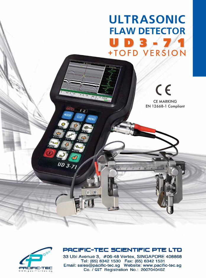
FLAW DETECTOR UD371 UD371 +TOFD VERSION ULTRASONIC CE MARKING EN 126681 Compliant
Transcript of FLAW DETECTOR U D 3 7 1 - Pacific-Tec Scientific Pte Ltd · UD371 ultrasonic flaw detector provides...
FLAW DETECTOR
UU DD 33 �� 77 11UU DD 33 �� 77 11+ T O F D V E R S I O N
ULTRASONIC
CE MARKING
EN 12668�1 Compliant

The colors of light ALARM by every gate corre�spond to them. Application of three�level gatesmakes it possible to estimate the risk of detect�ed defects.
• The sound alarm going�off level is setup by an operator by a specific gate.• The mode (when the preset level is tran�scended or not) is set up by an operator forevery gate independently. When using three�level gates it is possible
to register echo�signals at different levels rela�tive to the acceptance level. It will permit torecord echo�signals from developing defectsand monitor defects in the program of testingresults viewing what is necessary for carrying
UD3�71 FLAW DETECTORADVANTAGES
PURPOSE UD3�71 flaw detector is an ultrasonic gene�ral�purpose flaw detector which is intended for:• manual non�destructive testing of products
for detection of defects such as discontinuityand inhomogeneity of material in raw stock,finished items, in�process goods, welded, sol�dered, bolt, riveted and other joints;
• measurement of defects depth and othercoordinates;
• measurement of various items thickness atone�way access to them;
• measurement of signals (reflected fromdefects) amplitudes ratio;
• measurement of equivalent defects dimensions;• assessment of sound velocity in sundry
materials.Flaw detector is able to test materials and
products with sound velocity from 1500 m/s to15 000 m/s.
UD3�71 ultrasonic flaw detector provides thetesting of weld joints and base materials, andalso thickness measurement of monometals,bimetals in correspondence with the regulatorydocuments requirements in various industrialsectors.
UD3�71 edditionally has TOFD technique option.
2
out ultrasonic testing (UT) of importantobjects. Three�level gates as well as convenientsound and light defect alarm system allow toassess the detected discontinuity dimensionsquickly and qualitatively.
• Min. instrument dimensions � no more than188 х 107 х 78 mm � assure high instrumentergonomics and operation simplicity.
• Various A�scan display forms: RF/full wave/+half wave/�half wave.
• Dynamic change of generating path charac�teristics depending on the switched�on fre�quency filters.
• Information display forms: А�scan, B�scan,corrosion map.
• USB slave.• Flaw detector can be operated at the ambient
temperature from minus 30 to +50 0С.• Flaw detector case protection level from solid
bodies and water penetration corresponds toIР65; flaw detector is also resistant to ioniz�ing radiation impact and is meant for opera�tion in increased humidity conditions.
• Optionaly flaw detector can be configuratedwith removable storage battery.
• Availability of two independent measurementgates with the defects alarm system (soundand light) by each gate. At the same time,every gate hasTHREE GOING�OFF LEVELS:
"ACCEPTANCE"; "REGISTRATION"; "SEARCH" are marked on the flaw detector
screen in "RED", "BLUE" and "GREEN" color.
3
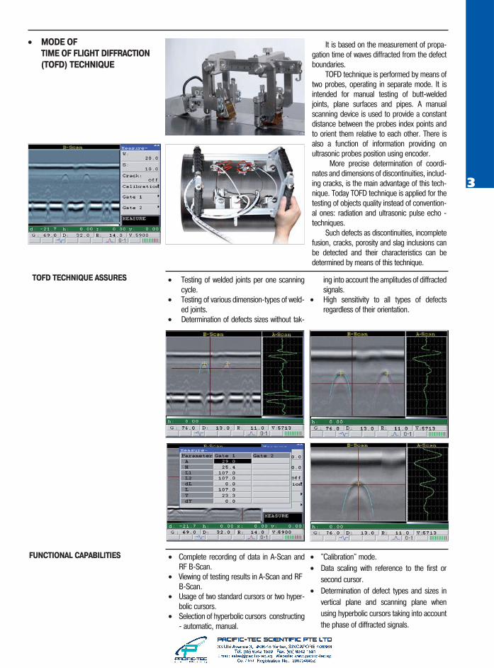
• MODE OF
TIME OF FLIGHT DIFFRACTION
(TOFD) TECHNIQUE
TOFD TECHNIQUE ASSURES
FUNCTIONAL CAPABILITIES
It is based on the measurement of propa�gation time of waves diffracted from the defectboundaries.
TOFD technique is performed by means oftwo probes, operating in separate mode. It isintended for manual testing of butt�weldedjoints, plane surfaces and pipes. A manualscanning device is used to provide a constantdistance between the probes index points andto orient them relative to each other. There isalso a function of information providing onultrasonic probes position using encoder.
More precise determination of coordi�nates and dimensions of discontinuities, includ�ing cracks, is the main advantage of this tech�nique. Today TOFD technique is applied for thetesting of objects quality instead of convention�al ones: radiation and ultrasonic pulse echo �techniques.
Such defects as discontinuities, incompletefusion, cracks, porosity and slag inclusions canbe detected and their characteristics can bedetermined by means of this technique.
• Testing of welded joints per one scanningcycle.
• Testing of various dimension�types of weld�ed joints.
• Determination of defects sizes without tak�
ing into account the amplitudes of diffractedsignals.
• High sensitivity to all types of defectsregardless of their orientation.
• Complete recording of data in A�Scan andRF B�Scan.
• Viewing of testing results in A�Scan and RF B�Scan.
• Usage of two standard cursors or two hyper�bolic cursors.
• Selection of hyperbolic cursors constructing� automatic, manual.
• "Calibration" mode.• Data scaling with reference to the first or
second cursor.• Determination of defect types and sizes in
vertical plane and scanning plane whenusing hyperbolic cursors taking into accountthe phase of diffracted signals.
4
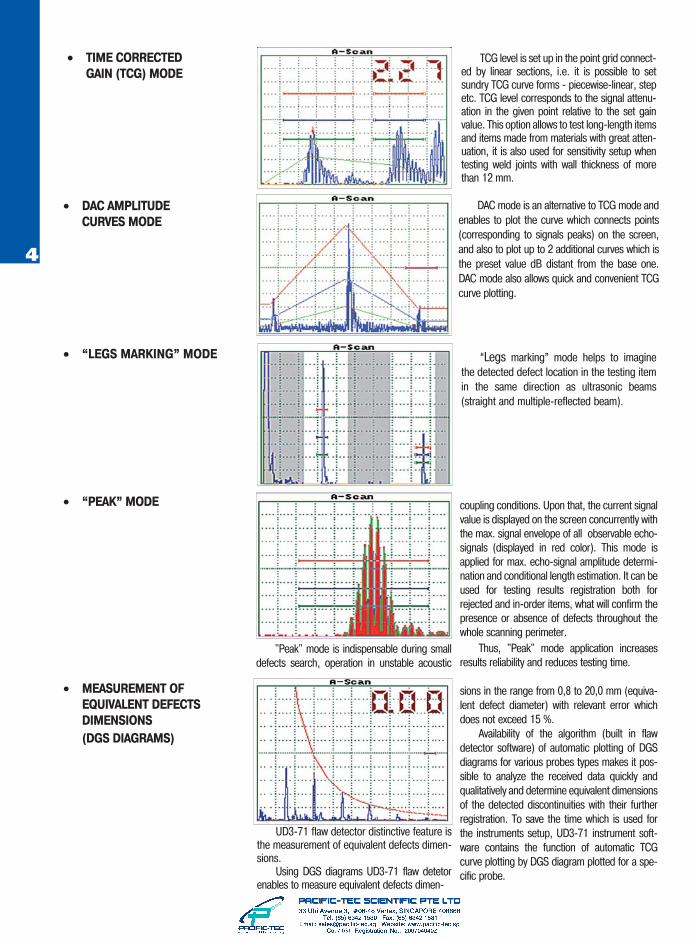
“Legs marking” mode helps to imaginethe detected defect location in the testing itemin the same direction as ultrasonic beams(straight and multiple�reflected beam).
DAC mode is an alternative to TCG mode andenables to plot the curve which connects points(corresponding to signals peaks) on the screen,and also to plot up to 2 additional curves which isthe preset value dB distant from the base one.DAC mode also allows quick and convenient TCGcurve plotting.
• “LEGS MARKING” MODE
• MEASUREMENT OF
EQUIVALENT DEFECTS
DIMENSIONS
(DGS DIAGRAMS)
• DAC AMPLITUDE
CURVES MODE
"Peak" mode is indispensable during smalldefects search, operation in unstable acoustic
• “PEAK” MODE
UD3�71 flaw detector distinctive feature isthe measurement of equivalent defects dimen�sions.
Using DGS diagrams UD3�71 flaw detetorenables to measure equivalent defects dimen�
TCG level is set up in the point grid connect�ed by linear sections, i.e. it is possible to setsundry TCG curve forms � piecewise�linear, stepetc. TCG level corresponds to the signal attenu�ation in the given point relative to the set gainvalue. This option allows to test long�length itemsand items made from materials with great atten�uation, it is also used for sensitivity setup whentesting weld joints with wall thickness of morethan 12 mm.
• TIME CORRECTED
GAIN (TCG) MODE
coupling conditions. Upon that, the current signalvalue is displayed on the screen concurrently withthe max. signal envelope of all observable echo�signals (displayed in red color). This mode isapplied for max. echo�signal amplitude determi�nation and conditional length estimation. It can beused for testing results registration both forrejected and in�order items, what will confirm thepresence or absence of defects throughout thewhole scanning perimeter.
Thus, "Peak" mode application increasesresults reliability and reduces testing time.
sions in the range from 0,8 to 20,0 mm (equiva�lent defect diameter) with relevant error whichdoes not exceed 15 %.
Availability of the algorithm (built in flawdetector software) of automatic plotting of DGSdiagrams for various probes types makes it pos�sible to analyze the received data quickly andqualitatively and determine equivalent dimensionsof the detected discontinuities with their furtherregistration. To save the time which is used forthe instruments setup, UD3�71 instrument soft�ware contains the function of automatic TCGcurve plotting by DGS diagram plotted for a spe�cific probe.

5
Mode of connection to PC is essentialfor data transmission from the flaw detectormemory to the computer memory and vice�versa. It is used for transmitting "А�scans"and "B�scans" to PC for reports creationon the basis of testing results or databases.
If required, the user can input setups forspecific testing types in flaw detector fromPC via in�built USB port what considerablyreduces the time of flaw detector prepara�tion for testing execution.
• SPECIAL PROGRAM
INTERFACE MODE
• MODE OF
CONNECTION TO PC
This mode is applied for solving special�purpose tasks. For example, when testingvarious single�type parts or when the parthas many testing areas. For solving this task"Special program interface" system is usedin UD3�71. The necessary standard setupsand program interface of "Special programinterface" enter flaw detector from PC. Theinput setups are protected from illegalchange by NDT inspector (operator).
ADDITIONAL SOFTWARE
Ultra UDх�7х � the programintended for processing testingresults of UD3�71 ultrasonic flawdetector and serves for functionalityextension and increase of instrumentoperation comfort. The present pro�gram assures operation with the datastored on PC
Memory elements operation enablesto perform the following functions:
• VIEW: setups, А�Scans and B�Scans
• CREATION AND EDITING:Setups
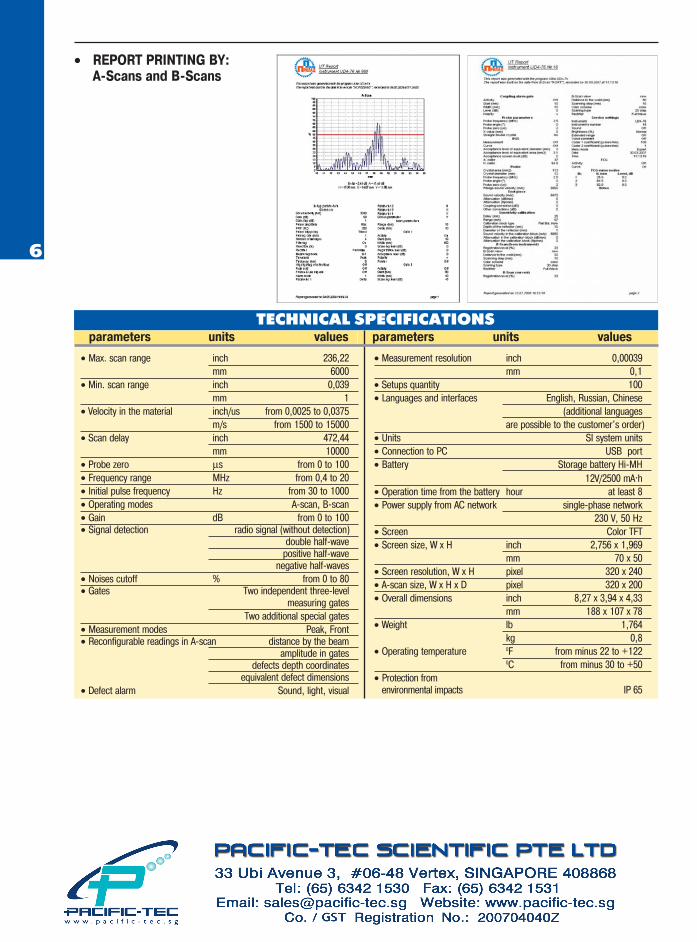
• REPORT PRINTING BY: А�Scans and B�Scans
А�Scans SetupsB�Scans
• RF SIGNAL
DISPLAY
To measure precisely the item thicknessand defects coordinates, the undetected RF(radiofrequency) signal is used what enablesto assure the measurement resolution of0,01 mm. Two modes of the point selectionon the signal oscillogram by which themeasurements are taken (automatic andmanual) are provided in the instrument.
RF А�Scan
RF B�Scan
PROMPRYLAD LC P.O.Box 43, Kiev 04080, Ukraine, tel./fax: +38 044 467�51�38(39)
E�mail:[email protected] www.ndt.com.ua
• Max. scan range inch 236,22mm 6000
• Min. scan range inch 0,039mm 1
• Velocity in the material inch/us from 0,0025 to 0,0375m/s from 1500 to 15000
• Scan delay inch 472,44mm 10000
• Probe zero μs from 0 to 100• Frequency range МHz from 0,4 to 20• Initial pulse frequency Hz from 30 to 1000• Operating modes А�scan, B�scan• Gain dB from 0 to 100• Signal detection radio signal (without detection)
double half�wavepositive half�wave
negative half�waves• Noises cutoff % from 0 to 80• Gates Two independent three�level
measuring gatesTwo additional special gates
• Measurement modes Peak, Front• Reconfigurable readings in А�scan distance by the beam
amplitude in gatesdefects depth coordinates
equivalent defect dimensions• Defect alarm Sound, light, visual
• Measurement resolution inch 0,00039mm 0,1
• Setups quantity 100• Languages and interfaces English, Russian, Chinese
(additional languagesare possible to the customer's order)
• Units SI system units• Connection to PC USB port• Battery Storage battery Hi�MH
12V/2500 mА.h• Operation time from the battery hour at least 8• Power supply from AC network single�phase network
230 V, 50 Hz• Screen Color TFT• Screen size, W x H inch 2,756 х 1,969
mm 70 х 50• Screen resolution, W x H pixel 320 х 240• А�scan size, W x H x D pixel 320 х 200• Overall dimensions inch 8,27 х 3,94 х 4,33
mm 188 х 107 х 78• Weight lb 1,764
kg 0,8• Operating temperature 0F from minus 22 to +122
0C from minus 30 to +50• Protection from
environmental impacts IP 65
TECHNICAL SPECIFICATIONSparameters units values parameters units values
• REPORT PRINTING BY:А�Scans and B�Scans
6


