![INDEX [] · pages list of abbreviations: 2 accelerator cables: 3-26 bonnet cables: 27-29 brake cables: 30-56 clutch cables: 57-63 gear shift cables: 64-67 speedometer cables](https://static.fdocuments.us/doc/165x107/5e80d4d1ff6b4555b218bdc3/index-pages-list-of-abbreviations-2-accelerator-cables-3-26-bonnet-cables.jpg)
FLAMEX CABLES TO DESIGN MOBILITY SOLUTIONS
106
FLAMEX ® CABLES TO DESIGN MOBILITY SOLUTIONS
Transcript of FLAMEX CABLES TO DESIGN MOBILITY SOLUTIONS

FLAM
EX®
CAB
LES
TO D
ESIG
N M
OBIL
ITY
SOLU
TION
S
FLAMEX® CABLES TO DESIGN MOBILITY SOLUTIONS
EDIT
ION
2020

FLAMEX® CABLE SOLUTIONS & SERVICES ........................................4
LOW VOLTAGE CONTROL CABLES .................................................................6FLAMEX® RANGE: EN 50306
FLAMEX® EN 50306-2 M
FLAMEX® EN 50306-3 MMS
FLAMEX® EN 50306-4 MM
FLAMEX® EN 50306-4 MMS
FLAMEX® EN 50306-4 MMM
FLAMEX® EN 50306-4 MMS
POWER CABLES REDUCED INSULATION THICKNESS ....24FLAMEX® RANGE: EN 50264
FLAMEX® EN 50264-3-1 M & MM
FLAMEX® EN 50264-3-1 MMS
FLAMEX® EN 50264-3-2 MM
FLAMEX® EN 50264-3-2 MMS
FLAMEX® 4GKW
HIGH TEMPERATURE FLEXIBLE POWER CABLES ...................40FLAMEX® RANGE: EN 50382-2
FLAMEX® EN 50382-2 F
FLAMEX® EN 50382-2 FF
FLAMEX® EN 50382-2 FXZ
FLAMEX® EN 50382-2 FFXS
COMMUNICATION CABLES.....................................................................................52FLAMEX® ETHERNET, WTB, MVB, CAN BUS
FLAMEX® OPTICAL FIBER CABLES
FLAMEX® LOW LOSS COAXIAL
FLAMEX® KX/RG COAXIAL
Table of contents
2

FIRE RESISTANT CABLES ................................................................................................66FLAMEX® RANGE: EN 50200
FLAMEX® MSZ
FLAMEX® (N)MHXAF-FR
FLAMEX® 4GKW–FR/HXAFOE-FR
FLAMEX® SI-FR TYPE EN 50382-2
FLAMEX® ETHERNET-FR
HV LOOPS & ACCESSORIES ...................................................................................84FLAMEX® (N)TMCGCHXOE
READY-TO-INSTALL PRE-ASSEMBLED HV CABLES
SEPARABLE HV CONNECTORS
HV TERMINATIONS
SPECIALTIES ......................................................................................................................................94FLAMEX® HYBRIDS & JUMPERS
CURRENT RATING ....................................................................................................................98
Symbols ..................................................................................................................................................104
3

FLAMEX® Cable Solutions & Services
Nexans can supply the hundreds of specialty products necessary to fit out a complete trainset. FLAMEX® cables are conform to EN 45545-2 i-e. products are halogen-free, non-toxic, non-corrosive, low smoke, flame and fire retardant. Our cables are also designed to withstand fire tests according to national or international standards including NFPA 130 or GOST-R 31565.
Control cables EN 50306 seriesThin wall single or multi-core, shielded or unshielded are used for the wiring of electronic equipment in low voltage applications: doors, lighting, converters/transformers.
Power cables EN 50264 3 & EN 50382-2 seriesFlexible single and multi-core cables to meet the power needs. Silicone-based Power cables are designed to withstand extreme operating temperatures.
Tailored Communication cablesDatabus cables that meet Profibus, MVB, WTB or Ethernet protocols for passenger video services/surveillance and vital equipment. Coaxial cables for multimedia and GSM radio transmissions. Optical fiber cables to bring high bandwidth for
FLAMEX® A COMPLETE RANGE OF PRODUCTS
onboard services i-e passenger information and train.
Fire resistant cables EN 50200A wide range of fire resistant control, power and communication cables for safety systems (emergency lighting, fire detection, warning systems, door opening, etc.)
Jumpers/HybridsReliable flexible power or customized hybrid cables for intercars and bogies.
HV cable assembliesHigh voltage tailored assemblies for 25kV. A wide range of cable cross-sections allows to fit with any project requirement.
4

Smart Inventory ManagementReduce costs in operation, optimize cash flow, free up warehouse space, simplify project management.
This Solution is using RFID technology on drums to monitor the inventory of cables along the entire supply chain. The benefits are manifold:• 100% material availability with a reduced
inventory and storage space need• 24/7 real time visibility of the entire cable
portfolio • Simplification of ordering process, incoming
goods reception, expedition processes
A TAILORED SERVICE PACKAGE TO SUPPORT YOUR OPERATIONAL CONCERNS AND CHALLENGES
Engineering of electrical cablingAssess and improve reliability of the electrical wiring, reduce the total cost-of-ownership, make cable purchases leaner.
70% of the total cost of an electrical system is driven and locked by the design. Finding the optimum balance between power efficiency, reliability and cost competitiveness is a tremendous challenge. Architecture design service consists in re-engineering cabling systems to optimize cable sizing and routing, reduce the complexity of the bill of materials thanks to state of the art simulation and methodologies.
Cable Recycling Receive money back in exchange for your leftover cables, to positively contribute to the environment, to respect regulations on waste.
Rolling stock companies in Europe rely in Nexans’ expertise to recycle their cable waste. This service allows you to comply with the increasing environment regulations and at the same time provides a source of revenues from scraps. Nexans, as a recycling expert ensures an end-to-end service including the collection and transport of cable scraps, recovery in its own treatment plants, and release of the official traceability and compliance documentation and of course the payment.
5
FLA
MEX
® C
ABL
E SO
LUTIO
NS
& SE
RVIC
ES

6

LOW VOLTAGE CONTROL CABLESFLAMEX® RANGE: EN 50306 ...................................................................... 8
FLAMEX® EN 50306-2 M ......................................................................... 13
FLAMEX® EN 50306-3 MMS .................................................................... 14
FLAMEX® EN 50306-4 MM ....................................................................... 16
FLAMEX® EN 50306-4 MMS ..................................................................... 18
FLAMEX® EN 50306-4 MMM .................................................................... 20
FLAMEX® EN 50306-4 MMS ..................................................................... 22
LOW
VO
LTA
GE
CON
TRO
L CA
BLES
7

MAIN CHARACTERISTICS• FLAMEX® EN 50306 cables
are available in every type of construction for internal and external uses: - single core (unscreened or screened and sheathed) - multicore and pairs - other constructions on request (triple, etc.)
• Operating temperature: from - 40°C up to +105°C able to whistand -50°C
• Rating voltage: 300 V AC / 410 V DC acc. EN 50355 table 2
• Cross-sections: from 0.50 mm² to 2.5 mm² in standard version
STANDARDS• FLAMEX® EN 50306 cables
are conform to EN 45545-2. On top of that, the cables are designed to withstand fire tests according NFPA 130 and GOST-R 31565
MAIN PROPERTIES• Low smoke emission
according to IEC/EN 61034-2
• Low toxicity (ITC<3) and corrosivity of released gases after burning: - Halogen-free content according to IEC/EN 60754-1 - pH > 4.3 according to IEC/EN 60754-2 - Conductivity < 100 μS/cm to IEC 60754-2
• High mechanical resistance (against abrasion, tnotch propagation and cut through): no additional protection required
• Excellent chemical resistance (against acid, alkali, oil, fuel…)
APPLICATIONSFLAMEX® control cables are particularly recommended for the wiring of electronic equipment in low voltage applications.Designed to conform to EN 50306, the control cables are intended for rolling stock applications where special fire performances are required: flame and fire retardant, halogen-free, low smoke emission, low toxicity and low corrosivity of fumes.
A 125°C conductor temperature is allowed for a 20,000 hours cumulate working time.
ADVANTAGES• Developed by the Nexans R&D laboratories,
the insulation shows an excellent mechanical resistance to abrasion, notch propagation and cut through, but also a very good resistance to chemical agents.
• Flexible and easy to strip, this single-layer insulation is designed to meet the stringent requirements of our customers during cabling operations.
• They allow weight and space saving (thin wall insulation: 0.2 to 0.3 mm insulation thickness).
• One EN standard available with two industrial processes (silane and e-beam crosslinking).
FLAMEX® EN 50306Thin wall halogen-free wires & cables for low voltage applications
8
LOW VOLTAGE CONTROL CABLES

GUIDELINES
EN 50306 TYPESSINGLECORE
CABLES
MULTICORECABLES
MULTIPAIR CABLES
OVERALLSCREEN
OUTER SHEATH MINIMUM THICKNESS
PAGE
EN 50306-2 Category M • - 17
EN 50306-3 Category MMS • • 0.20 mm 18
EN 50306-4 Table 1 Class P Category MMShort designation: EN 50306-4 1P • 0.42 mm 20
EN 50306-4 Table 1 Class E Category MM Short designation: EN 50306-4 1E • 1.00 mm 21
EN 50306-4 Table 3 Class P Category MMSShort designation: EN 50306-4 3P • • 0.42 mm 22
EN 50306-4 Table 3 Class E Category MMSShort designation: EN 50306-4 3E • • 1.00 mm 23
EN 50306-4 Table 5 Class P Category MMMShort designation: EN 50306-4 5P • 0.56 mm 24
EN 50306-4 Table 5 Class E Category MMMShort designation: EN 50306-4 5E • 1.00 mm 25
EN 50306-4 Table 7 Class P Category MMSShort designation: EN 50306-4 P • • 0.56 mm 26
EN 50306-4 Table 7 Class E Category MMSShort designation: EN 50306-4 E • • 1.00 mm 27
Extra low temperature & extra oil and fuel resistance of insulation and sheath acc. to category M.
FIRE PROPERTIESPARAMETER VALUE STANDARD
Hazard level HL3 EN 45545-2
Flame propagation - IEC/EN 60332-1-2
Fire propagation - bunched cables - EN 50305-9.1
Evolution of HCl < 0.5 % IEC/EN 60754-1
pH > 4.3 IEC/EN 60754-2
Conductivity < 10 μS/mm IEC/EN 60754-2
Smoke emission > 70 % IEC/EN 61034-2
Toxicity index of insulation < 6 EN 50305-9.2
Toxicity index of sheath (for sheathed types) < 3 EN 50305-9.2
LOW
VO
LTA
GE
CON
TRO
L CA
BLES
9

EN 50306-2 and EN 50306-3 are used for rolling stock as fixed wiring or wiring where limited flexing in operation is encountered.
EN 50306-4 types are specified used in PROTECTED situations (Class P: minimum thickness of sheath 0.42 mm) and EXPOSED situations (Class E minimum thickness of sheath 1 mm). They are used for rolling stock as fixed wiring or wiring where limited flexing in operation is encountered. The class E cables could be installed outside the vehicules.
10
LOW VOLTAGE CONTROL CABLES

LOW
VO
LTA
GE
CON
TRO
L CA
BLES
11

Strictly halogen-free, these control wires and cables combine the advantages of small size, lightweight, high chemical resistance and high mechanical properties. They are recommended for installation in all types of railway vehicles. A 125°C conductor temperature is allowed during 20,000 hours cumulative working time for EN 50306-2 and 90°C for EN 50306-3 and EN 50306-4.
APPLICATION
1 ConductorFlexible stranded tinned copper wires according to EN 50306
2 InsulationThin wall of cross-linked halogen-free material acc. to EN 50306
3 Screen(for screened versions)Tinned copper braid Optional separator tape
4 Outer sheath(for EN 50306-3 and -4 versions)Cross-linked compound type EM 104Oil, fuel, ozone and UV resistantColour: black
DESIGN
Marking of FLAMEX® cables complies with EN 50306 (see details hereafter)
MARKING
Insulation: white, numbered 1 to n
Dynamic use: 10 x outer diameterStatic use: - 3 x outer diameter - 10 x outer diameter for shielded cables Permissible current
capacities and cabling rules given in EN 50355 andEN 50343
COLOUR CODES
BENDING RADIUS
GUIDE TO USE
FLAMEX® EN 50306 cables are conform to EN 45545-2. On top of that, the cables are designed to withstand fire tests according to NFPA 130 and GOST-R 31565
FIRE SAFETY STANDARDS
Conductor temperature: -40°C/+105°C/+125°C for EN 50306-2 -40°C/+90°C/+120°C for EN 50306-3 or -4
EMIOperating temp
- 40°C to +105°C
Low corrosivity of combustion
gasesIEC/EN 60754-2
Low toxicityEN 50305-9.2
Low smokeemission
IEC/EN 61034-2
Halogen-freeIEC/EN 60754-1
IEC 60684-2
FlexibleGood chemical Resistance
(oil, fuel, acid…)
Screenedversion
Flame and Fire retardant
IEC/EN 60332-1-2IEC/EN 60332-3EN 50305-9.1
Unscreenedwires
Screened multicore/pair
cables
1
2
12
FLAMEX® EN 50306FLEXIBLE THIN WALL INSULATED WIRES AND CABLES
LOW VOLTAGE CONTROL CABLES

LOW
VO
LTA
GE
CON
TRO
L CA
BLES
13
FLA
MEX
® E
N 5
0306
-2 M
FLAMEX EN 50306-2 - 300 V - 1 x cross-section - M - week/year batch number
Marking
FLAMEX® - EN 50306-2 CATEGORY M Unscreened and unsheathed single core cables Thin wall insulation
NEXANS REFERENCE NUMBER OF CORES
X CROSS-SECTION [mm²]
CONDUCTOR INSULATION MAX. COND.
RESISTANCE[Ohm/km]
APPROX.WEIGHT[kg/km]Silane
technologyE-beam
technology Constructionn x diam.
[mm]
Max. diameter
[mm]
Min. diameter
[mm]
Max. diameter
[mm]
2PG198 41300227 1 x 0.5 19 x 0.18 0.95 1.15 1.45 40.1 6.0
2PG199 41300327 1 x 0.75 19 x 0.23 1.15 1.35 1.65 26.7 8.5
2PG200 41300427 1 x 1.0 19 x 0.25 1.30 1.45 1.80 20.0 10.5
2PF779 41300527 1 x 1.5 19 x 0.30 1.65 1.95 2.30 13.7 16.0
2PG201 41300627 1 x 2.5 19 x 0.40 2.15 2.50 2.85 8.21 26.5

14
FLAMEX® - EN 50306-3 CATEGORY MM - S Single core and multicore cables (pairs, triples and quads) screened and thin wall sheathed Thin wall insulation/Thin wall sheath (minimum 0.20 mm) type EM 104Base core Each insulated single core is conform to the requirements given in EN 50306-2
NEXANSREFERENCE
NUMBER OF CORES X CROSS-SECTION [mm²]
OVERALL DIAMETER APPROX. WEIGHT[kg/km]Minimum [mm] Maximum [mm]
2PH184 1 x 0.50 2.30 2.80 14
2PG960 2 x 0.50 3.50 4.30 25
2PG963 3 x 0.50 3.70 4.50 33
2PH189 4 x 0.50 4.00 5.00 43
2PI378 6 x 0.50 5.5 6.50 75
2PI811 8 x 0.50 6.10 7.10 88
2PH185 1 x 0.75 2.50 3.00 17
2PG961 2 x 0.75 3.90 4.70 31
2PG964 3 x 0.75 4.00 5.00 43
2PH190 4 x 0.75 4.50 5.50 56
2PJ842 6 x 0.75 6.10 7.10 92
2PI361 8 x 0.75 7.30 8.30 119
2PH186 1 x 1.00 2.70 3.20 20
2PG962 2 x 1.00 4.20 5.20 37
2PG965 3 x 1.00 4.50 5.50 52
2PG966 4 x 1.00 5.00 6.00 65
2PM688 6 x 1.00 6.30 7.30 104
2PM706 8 x 1.00 7.50 8.50 125
2PH187 1 x 1.50 3.10 3.60 28
2PF780 2 x 1.50 5.10 6.10 55
2PH191 3 x 1.50 5.40 6.40 75
2PH192 4 x 1.50 6.00 7.00 100
2PK766 6 x 1.50 7.30 8.30 154
2PM156 8 x 1.50 8.50 9.50 215
2PH188 1 x 2.50 3.60 4.40 43
2PH193 2 x 2.50 6.40 7.40 87
2PH194 3 x 2.50 6.80 7.80 124
2PH195 4 x 2.50 7.50 8.50 158
Other constructions on request
FLAMEX® EN 50306-3FLEXIBLE THIN WALL INSULATED WIRES AND CABLES
Cores: by printed numbersExternal sheath: FLAMEX EN 50306-3 - 300 V - number of cores x cross-section - MM-S-90 - week/year batch number
Marking

LOW
VO
LTA
GE
CON
TRO
L CA
BLES
15
FLA
MEX
® E
N 5
0306
-3 M
MS

16
FLAMEX® EN 50306-4FLEXIBLE THIN WALL INSULATED WIRES AND CABLES
Cores: by printed numbersExternal sheath: FLAMEX EN 50306-4 - 1P - 300 V - number of cores x cross-section - MM-90 - week/year batch number
Marking
FLAMEX® EN 50306-4 TABLE 1 CLASS P CATEGORY MM Unscreened and sheathed multicore cables Thin wall insulation/Standard wall sheath (minimum 0.42 mm) type EM 104Base core Each insulated single core is conform to the requirements given in EN 50306-2
NEXANS REFERENCE NUMBER OF CORES X CROSS-SECTION [mm²]
OVERALL DIAMETER APPROX. WEIGHT[kg/km]Silane technology E-beam technology Minimum [mm] Maximum [mm]
2PH304 41352210 2 x 0.50 3.50 4.50 27
2PH305 41352310 3 x 0.50 3.80 4.80 34
2PG693 41352410 4 x 0.50 4.10 5.10 41
2PH306 41352710 7 x 0.50 4.90 5.90 63
2PH307 41350410 13 x 0.50 7.30 8.30 121
2PH308 41350510 19 x 0.50 8.10 9.10 160
2PH309 41350610 37 x 0.50 10.80 12.00 286
2PG694 41353210 2 x 0.75 3.95 4.95 33
2PG695 41353310 3 x 0.75 4.20 5.20 43
2PG696 41353410 4 x 0.75 4.60 5.60 54
2PH310 41353710 7 x 0.75 5.50 6.50 84
2PH311 41350710 13 x 0.75 8.20 9.20 161
2PH312 41350810 19 x 0.75 9.00 10.20 216
2PH313 41350910 37 x 0.75 12.20 13.40 390
2PH314 41358010 48 x 0.75 13.90 15.50 497
2PG697 41354210 2 x 1.00 4.30 5.30 41
2PG698 41354310 3 x 1.00 4.60 5.60 46
2PG699 41354410 4 x 1.00 4.90 5.90 58
2PG700 41354710 7 x 1.00 6.00 7.00 105
2PG701 41371310 13 x 1.00 8.70 9.90 198
2PG702 41371910 19 x 1.00 9.80 11.00 268
2PH315 41358110 37 x 1.00 13.30 14.50 491
2PG703 41355210 2 x 1.50 5.00 6.00 51
2PG704 41355310 3 x 1.50 5.30 6.30 67
2PG705 41355410 4 x 1.50 6.00 7.00 85
2PG706 41355710 7 x 1.50 7.70 8.70 158
2PG707 41375110 13 x 1.50 10.70 11.90 277
2PG708 41358210 19 x 1.50 12.00 13.20 378
2PG709 41375310 37 x 1.50 16.20 17.80 715
2PG710 41356210 2 x 2.50 6.70 7.70 86
2PG711 41356310 3 x 2.50 7.70 8.10 119
2PG712 41356410 4 x 2.50 7.90 8.90 147
Other constructions on request

LOW
VO
LTA
GE
CON
TRO
L CA
BLES
17
Cores: by printed numbersExternal sheath: FLAMEX EN 50306-4 - 1E - 300 V - number of cores x cross-section - MM-90 - week/year batch number
Marking
FLA
MEX
® E
N 5
0306
-4 M
M
FLAMEX® EN 50306-4 TABLE 1 CLASS E CATEGORY MM Unscreened and sheathed multicore cables Thin wall insulation/Standard wall sheath (minimum 1.00 mm) type EM 104Base core Each insulated single core is conform to the requirements given in EN 50306-2
NEXANS REFERENCE NUMBER OF CORES X CROSS-SECTION [mm²]
OVERALL DIAMETER APPROX. WEIGHT[kg/km]Silane technology E-beam technology Minimum [mm] Maximum [mm]
2PH316 41352217 2 x 0.50 4.90 5.90 48
2PH317 41352317 3 x 0.50 5.10 6.10 56
2PH318 41352417 4 x 0.50 5.50 6.50 60
2PH319 41350417 7 x 0.50 6.30 7.30 80
2PH320 41352717 13 x 0.50 8.30 9.30 132
2PH321 41350517 19 x 0.50 9.00 10.20 172
2PH322 41350617 37 x 0.50 12.30 13.50 310
2PH323 41353217 2 x 0.75 5.30 6.30 57
2PH324 41353317 3 x 0.75 5.50 6.50 67
2PH325 41353417 4 x 0.75 6.00 7.00 79
2PH326 41353717 7 x 0.75 6.90 7.90 114
2PH327 41350717 13 x 0.75 9.10 10.30 189
2PH328 41350817 19 x 0.75 10.00 11.20 246
2PH329 41350917 37 x 0.75 13.20 14.40 433
2PH330 41358017 48 x 0.75 14.80 16.40 546
2PH331 41354217 2 x 1.00 5.60 6.60 62
2PH332 41354317 3 x 1.00 5.80 6.90 75
2PG967 41354417 4 x 1.00 6.30 7.30 94
2PG968 41354717 7 x 1.00 7.30 8.30 136
2PG969 41371317 13 x 1.00 9.70 10.90 231
2PG970 41371917 19 x 1.00 10.70 11.90 300
2PH333 41358117 37 x 1.00 14.00 15.60 533
2PH334 41355217 2 x 1.50 6.30 7.30 81
2PH335 41355317 3 x 1.50 6.60 7.60 100
2PG972 41355417 4 x 1.50 7.40 8.40 123
2PG428 41355717 7 x 1.50 8.60 9.80 185
2PG973 41375117 13 x 1.50 11.70 12.90 319
2PG429 41358217 19 x 1.50 13.00 14.20 430
2PG971 41375317 37 x 1.50 17.20 18.80 768
2PH336 41356217 2 x 2.50 7.70 8.70 119
2PH337 41356317 3 x 2.50 8.10 9.10 151
2PG974 41356417 4 x 2.50 8.80 10.00 187
Other constructions on request

18
FLAMEX® EN 50306-4FLEXIBLE THIN WALL INSULATED WIRES AND CABLES
Cores: by printed numbersExternal sheath: FLAMEX EN 50306-4 - 3P - 300 V - number of cores x cross-section - MM-S-90 - week/year batch number
Marking
FLAMEX® EN 50306-4 TABLE 3 CLASS P CATEGORY MM - S Screened and sheathed multicore cables Thin wall insulation/Standard wall sheath (minimum 0.42 mm) type EM 104Base core Each insulated single core is conform to the requirements given in EN 50306-2
NEXANS REFERENCE NUMBER OF CORES X CROSS-SECTION [mm²]
OVERALL DIAMETER APPROX. WEIGHT[kg/km]Silane technology E-beam technology Minimum [mm] Maximum [mm]
2PG715 41362210 2 x 0.50 4.10 5.10 36
2PG716 41362310 3 x 0.50 4.30 5.30 44
2PG413 41362410 4 x 0.50 4.70 5.70 54
2PG717 41362610 6 x 0.50 5.50 6.50 75
2PG718 41362810 8 x 0.50 6.00 7.00 90
2PG719 41363210 2 x 0.75 4.50 5.50 43
2PG720 41363310 3 x 0.75 4.70 5.70 54
2PG721 41363410 4 x 0.75 5.20 6.20 69
2PG722 41363610 6 x 0.75 6.10 7.10 95
2PG723 41363810 8 x 0.75 6.60 7.60 118
2PG414 41364210 2 x 1.00 4.70 5.70 51
2PG415 41364310 3 x 1.00 5.10 6.00 64
2PG724 41364410 4 x 1.00 5.50 6.50 78
2PG725 41364610 6 x 1.00 6.60 7.60 111
2PG726 41364810 8 x 1.00 7.70 8.70 156
2PG727 41365210 2 x 1.50 5.70 6.70 70
2PG728 41365310 3 x 1.50 6.00 7.00 90
2PG729 41365410 4 x 1.50 6.60 7.60 114
2PG730 41365610 6 x 1.50 8.30 9.30 178
2PG731 41365810 8 x 1.50 8.90 10.10 210
2PG732 41366210 2 x 2.50 7.30 8.30 116
2PG733 41366310 3 x 2.50 7.70 8.70 151
2PG734 41366410 4 x 2.50 8.40 9.60 192
Other constructions on request

LOW
VO
LTA
GE
CON
TRO
L CA
BLES
19
Cores: by printed numbersExternal sheath: FLAMEX EN 50306-4 - 3E - 300 V - number of cores x cross-section - MM-S-90 - week/year batch number
Marking
FLA
MEX
® E
N 5
0306
-4 M
MSFLAMEX® EN 50306-4 TABLE 3 CLASS E CATEGORY MM - S
Screened and sheathed multicore cables Thin wall insulation/Standard wall sheath (minimum 1.00 mm) type EM 104Base core Each insulated single core is conform to the requirements given in EN 50306-2
NEXANS REFERENCE NUMBER OF CORES X CROSS-SECTION [mm²]
OVERALL DIAMETER APPROX. WEIGHT[kg/km]Silane technology E-beam technology Minimum [mm] Maximum [mm]
2PG843 41362217 2 x 0.50 5.50 6.50 58
2PG844 41362317 3 x 0.50 5.70 6.70 67
2PG845 41362417 4 x 0.50 6.10 7.10 80
2PG846 41362617 6 x 0.50 6.90 7.90 105
2PG847 41362817 8 x 0.50 7.50 8.50 122
2PG848 41363217 2 x 0.75 5.90 6.90 68
2PG849 41363317 3 x 0.75 6.20 7.20 79
2PG850 41363417 4 x 0.75 6.50 7.50 96
2PH340 41363617 6 x 0.75 7.50 8.50 128
2PG851 41363817 8 x 0.75 8.20 9.20 156
2PG426 41364217 2 x 1.00 6.20 7.20 77
2PG852 41364317 3 x 1.00 6.50 7.50 95
2PG427 41364417 4 x 1.00 6.90 7.90 109
2PG853 41364617 6 x 1.00 8.00 9.00 158
2PG854 41364817 8 x 1.00 8.60 9.80 186
2PG855 41365217 2 x 1.50 7.10 8.10 97
2PG856 41365317 3 x 1.50 7.40 8.40 119
2PG857 41365417 4 x 1.50 8.00 9.00 148
2PG858 41365617 6 x 1.50 9.20 10.40 206
2PH341 41365817 8 x 1.50 10.20 11.40 245
2PG859 41366217 2 x 2.50 8.30 9.30 138
2PH342 41366317 3 x 2.50 8.60 9.80 171
2PG860 41366417 4 x 2.50 9.40 10.60 214
Other constructions on request

20
FLAMEX® EN 50306-4FLEXIBLE THIN WALL INSULATED WIRES AND CABLES
Cores: by printed numbersExternal sheath: FLAMEX EN 50306-4 - 5P - 300 V - number of cores x 2 x section - MMM-90 - week/year batch number
Marking
FLAMEX® EN 50306-4 TABLE 5 CLASS P CATEGORY MMM Individually screened and sheathed multipair cables Thin wall insulation/Standard wall external sheath (minimum 0.56 mm) type EM 104Base core Each insulated single core is conform to the requirements given in EN 50306-2
NEXANS REFERENCE NUMBER OF CORES X CROSS-SECTION [mm²]
OVERALL DIAMETER APPROX. WEIGHT[kg/km]Silane technology E-beam technology Minimum [mm] Maximum [mm]
2PH478 41322610 2 x 2 x 0.50 9.00 10.20 110
2PH479 41332610 3 x 2 x 0.50 9.60 10.80 150
2PH480 41342610 4 x 2 x 0.50 10.70 11.90 181
2PH481 41372610 7 x 2 x 0.50 13.00 14.20 282
2PH482 41322710 2 x 2 x 0.75 9.80 11.00 146
2PH483 41332710 3 x 2 x 0.75 10.5 11.70 185
2PH484 41342710 4 x 2 x 0.75 11.60 12.80 216
2PH485 41372710 7 x 2 x 0.75 14.00 15.60 335
2PH486 41322810 2 x 2 x 1.00 10.20 11.60 154
2PH487 41332810 3 x 2 x 1.00 10.90 12.10 196
2PH488 41342810 4 x 2 x 1.00 12.10 13.30 235
2PH489 41372810 7 x 2 x 1.00 14.60 16.20 390
2PH490 41322910 2 x 2 x 1.50 12.00 13.40 226
2PH491 41332910 3 x 2 x 1.50 13.10 14.30 288
2PH492 41342910 4 x 2 x 1.50 14.30 15.90 336
2PH493 41372910 7 x 2 x 1.50 17.60 19.20 563
Other constructions on request

LOW
VO
LTA
GE
CON
TRO
L CA
BLES
21
Cores: by printed numbersExternal sheath: FLAMEX EN 50306-4 - 5E - 300 V - number of cores x 2 x section - MMM-90 - week/year batch number
Marking
FLA
MEX
® E
N 5
0306
-4 M
MM
Cores: by printed numbersExternal sheath: FLAMEX EN 50306-4 - 5P - 300 V - number of cores x 2 x section - MMM-90 - week/year batch number
FLAMEX® EN 50306-4 TABLE 5 CLASS E CATEGORY MMM Individually screened and sheathed multipair cables Thin wall insulation/Standard wall external sheath (minimum1.00 mm) type EM 104Base core Each insulated single core is conform to the requirements given in EN 50306-2
NEXANS REFERENCE NUMBER OF CORES X CROSS-SECTION [mm²]
OVERALL DIAMETER APPROX. WEIGHT[kg/km]Silane technology E-beam technology Minimum [mm] Maximum [mm]
2PH343 41322617 2 x 2 x 0.50 10.10 11.30 159
2PH344 41332617 3 x 2 x 0.50 10.80 12.00 193
2PH345 41342617 4 x 2 x 0.50 11.80 13.00 200
2PH346 41372617 7 x 2 x 0.50 13.90 15.50 324
2PH347 41322717 2 x 2 x 0.75 10.90 12.10 185
2PH348 41332717 3 x 2 x 0.75 11.60 12.80 227
2PH349 41342717 4 x 2 x 0.75 12.80 14.00 267
2PH350 41372717 7 x 2 x 0.75 15.10 16.70 390
2PH351 41322817 2 x 2 x 1.00 11.30 12.50 195
2PH352 41332817 3 x 2 x 1.00 12.00 13.20 238
2PH353 41342817 4 x 2 x 1.00 13.20 14.40 279
2PH354 41372817 7 x 2 x 1.00 15.70 17.30 417
2PH355 41322917 2 x 2 x 1.50 13.30 14.50 275
2PF781 41332917 3 x 2 x 1.50 14.00 15.60 330
2PH356 41342917 4 x 2 x 1.50 15.50 17.10 393
2PG975 41372917 7 x 2 x 1.50 18.70 20.30 610
Other constructions on request

22
FLAMEX® EN 50306-4FLEXIBLE THIN WALL INSULATED WIRES AND CABLES
FLAMEX® EN 50306-4 TABLE 7 CLASS P CATEGORY MM - S Screened and sheathed multipair cables (overall screen) Thin wall insulation/Standard wall sheath (minimum 0.42 mm) type EM 104Base core Each insulated single core is conform to the requirements given in EN 50306-2
NEXANS REFERENCE NUMBER OF CORES X CROSS-SECTION [mm²]
OVERALL DIAMETER APPROX. WEIGHT[kg/km]Silane technology E-beam technology Minimum [mm] Maximum [mm]
2PG735 41322210 2 x 2 x 0.50 6.20 7.40 73
2PG736 41332210 3 x 2 x 0.50 6.50 7.70 86
2PG737 41342210 4 x 2 x 0.50 7.40 8.60 112
2PG738 41372210 7 x 2 x 0.50 8.80 10.00 163
2PG739 41322310 2 x 2 x 0.75 7.00 8.20 95
2PG740 41332310 3 x 2 x 0.75 7.30 8.50 113
2PG741 41342310 4 x 2 x 0.75 8.20 9.40 140
2PG742 41372310 7 x 2 x 0.75 9.90 11.10 215
2PG743 41322410 2 x 2 x 1.00 7.60 8.80 108
2PG744 41332410 3 x 2 x 1.00 7.90 9.10 130
2PG745 41342410 4 x 2 x 1.00 8.80 10.00 160
2PG746 41372410 7 x 2 x 1.00 10.80 12.00 252
2PG747 41322510 2 x 2 x 1.50 8.70 9.90 145
2PG748 41332510 3 x 2 x 1.50 9.20 10.40 181
2PG749 41342510 4 x 2 x 1.50 10.40 11.60 232
2PG750 41372510 7 x 2 x 1.50 13.10 14.30 386
Other constructions on request
Pairs: by printed numbersExternal sheath: FLAMEX EN 50306-4 - 7P - 300 V - number of cores x 2 x section - MM-S-90 - week/year batch number
Marking

LOW
VO
LTA
GE
CON
TRO
L CA
BLES
23
Pairs: by printed numbersExternal sheath: FLAMEX EN 50306-4 - 7E - 300 V - number of cores x 2 x section - MM-S-90 - week/year batch number
Marking
FLAMEX® EN 50306-4 TABLE 7 CLASS E CATEGORY MM - S Screened and sheathed multipair cables (overall screen) Thin wall insulation/Standard wall sheath (minimum 1.00 mm) type EM 104Base core Each insulated single core is conform to the requirements given in EN 50306-2
NEXANS REFERENCE NUMBER OF CORES X CROSS-SECTION [mm²]
OVERALL DIAMETER APPROX. WEIGHT[kg/km]Silane technology E-beam technology Minimum [mm] Maximum [mm]
2PG861 41322217 2 x 2 x 0.50 7.20 8.40 85
2PG862 41332217 3 x 2 x 0.50 7.50 8.70 99
2PG863 41342217 4 x 2 x 0.50 8.40 9.60 124
2PH357 41372217 7 x 2 x 0.50 9.75 10.95 177
2PG864 41322317 2 x 2 x 0.75 8.00 9.20 108
2PH358 41332317 3 x 2 x 0.75 8.35 9.55 128
2PH359 41342317 4 x 2 x 0.75 9.15 10.35 154
2PH360 41372317 7 x 2 x 0.75 10.75 11.95 226
2PG865 41322417 2 x 2 x 1.00 8.60 9.80 121
2PG866 41332417 3 x 2 x 1.00 8.90 10.10 145
2PH361 41342417 4 x 2 x 1.00 9.80 11.00 176
2PH362 41372417 7 x 2 x 1.00 11.55 12.75 260
2PH363 41322517 2 x 2 x 1.50 9.70 10.90 165
2PH364 41332517 3 x 2 x 1.50 10.10 11.30 196
2PH365 41342517 4 x 2 x 1.50 11.20 12.40 242
2PH366 41372517 7 x 2 x 1.50 13.50 14.70 382
Other constructions on request
FLA
MEX
® E
N 5
0306
-4 M
MS

24

POWER CABLES REDUCED INSULATION THICKNESSFLAMEX® RANGE: EN 50264 .................................................................... 26
FLAMEX® EN 50264-3-1 M & MM .............................................................. 28
FLAMEX® EN 50264-3-1 MMS ................................................................... 32
FLAMEX® EN 50264-3-2 MM ..................................................................... 34
FLAMEX® EN 50264-3-2 MMS ................................................................... 36
FLAMEX® 4GKW ...................................................................................... 38
POW
ER C
ABL
ES R
EDUC
ED
INSU
LATIO
N T
HICK
NES
S
25

MAIN CHARACTERISTICS• FLAMEX® EN 50264 cables
are available in every type of construction for internal and external uses: - single core (unscreened or screened and sheathed) - multicore
• Operating temperature: from - 40°C up to 90°C
• Rated voltage: From 0.6/1 kV to 3.6/6kV
• Cross-sections: from 0.50 to 300 mm²
STANDARDS• FLAMEX® EN 50264 cables
are conform to EN 45545-2. On top of that, the cables are designed to withstand fire tests according to NFPA 130 and GOST-R 31565
MAIN PROPERTIES• Low smoke emission
according to IEC/EN 61034-2
• Low toxicity (ITC<3) and corrosivity of released gases after burning: - Halogen-free content according to IEC/EN 60754-1 - pH > 4.3 according to IEC/EN 60754-2 - Conductivity < 100 μS/cm to IEC/EN 60754-2
• High mechanical resistance (against abrasion, tensile strength and cut through): no additional protection required
• Excellent chemical resistance (against acid, alkali, oil, fuel…)
APPLICATIONSFLAMEX® power cables are recommended for protected installation in railway vehicles (locomotives, trains, trolleybuses, etc.), switching station and control panels for installation in cable ducts, pipes and tubes. Designed to conform to EN 50264, the power cables are intended for rolling stock applications where special fire performances are required: flame and fire retardant, halogen-free, low smoke emission, low toxicity and low corrosivity of fumes. A 120°C conductor temperature is allowed for a 20,000 hours cumulate working time.
ADVANTAGES• Developed by the Nexans R&D laboratories,
rubber compounds show an excellent mechanical resistance to abrasion, tensile strength and cut through, but also a very good resistance to chemical agents.
• Flexible and easy to strip, our cables are designed to meet the stringent requirements of our customers during cabling operations.
FLAMEX® EN 50264Power halogen-free cables with reduced insulation thickness
26
POWER CABLES REDUCED INSULATION THICKNESS

GUIDELINESEN 50264 TYPES SINGLE
CORECABLES
MULTICORECABLES
INSUL. EN 50264-1
EI 109SCREENED
SHEATH EN 50264-1
EM 104PAGE
EN 50264-3-1 0.6/1 kV - Category M • • 33
EN 50264-3-1 1.8/3 kV - Category M • • • 33
EN 50264-3-1 1.8/3 kV - Category MM • • 34
EN 50264-3-1 1.8/3 kV - Category MMS • • • • 37
EN 50264-3-1 3.6/6 kV - Category MM • • 34
EN 50264-3-1 3.6/6 kV - Category MMS • • • • 37
EN 50264-3-2 0.6/1 kV - Category MM • • • 39
EN 50264-3-2 0.6/1 kV - Category MMS • • • • 41
4GKW TYPE EN 50264 1.8/3 kV • • • 43
Extra low temperature & extra oil and fuel resistance of insulation and sheath acc. to category M.
FIRE PROPERTIESPARAMETER VALUE STANDARD
Hazard level HL3 EN 45545-2
Flame propagation - EN 60332-1-2
Fire propagation - bunched cables - EN 60332-3-24/25 or EN 50305 depending on diameter
Evolution of HCl < 0.5 % IEC/EN 60754-1
pH >4.3 IEC/EN 60754-2
Conductivity < 10 μS/mm IEC/EN 60754-2
Smoke emission > 70 % IEC/EN 61034-2
Toxicity index < 3 EN 50305-9.2
FLAMEX® - EN 50264Properties
POW
ER C
ABL
ES R
EDUC
ED
INSU
LATIO
N T
HICK
NES
S
27

FLAMEX® EN 50264-3-1 M & MM power cables are used for fixed and protected installations. This product range is recommended for narrow spaces where an optimal bending radius is required. FLAMEX® cables are designed to withstand tough working conditions (oil, ozone, temperature variation, etc.). A 120°C conductor temperature is allowed for a 20,000 hours cumulative working time.
APPLICATION
1 ConductorFlexible stranded tinned copper class 5 according to IEC/EN 60228Optional separator tape
2 InsulationCross-linked compound type EI 109 according to EN 50264-1Oil, diesel, ozone and UV resistantColour: black (green/yellow on request)
3 Outer sheath for Type MMCross-linked compound type EM 104 according to EN 50264-1 Oil, diesel, ozone and UV resistant Colour: black
DESIGN
0.6/1 kVStatic use: 3 x outer diameterDynamic use: 5 x outer diameter1.8/3 kVStatic use: 3 x outer diameter (5 x D if D>10mm) Dynamic use: 6 x outer diameter3.6/6 kVStatic use: 4 x outer diameter (5 x D if D>10mm) Dynamic use: 10 x outer diameter
Permissible current capacities and cabling rules given in EN 50355 and EN 50343
BENDING RADIUS
GUIDE TO USE
FLAMEX® EN 50264 cables are conform to EN 45545-2. On top of that, the cables are designed to withstand fire tests according to NFPA 130 and GOST-R 31565
FIRE SAFETY STANDARDS
Conductor temperature: -40°C/+90°C/+120°C
Operating temp - 40°C to +90°C
Low corrosivity of combustion gasesIEC/EN 60754-2
Low toxicityEN 50305-9.2
Low smokeemission
IEC 61034-2
Halogen-freeIEC/EN 60754-1
IEC 60684-2
FlexibleClass 5
Good chemical Resistance
(oil, fuel, acid…)
Flame and Fire retardant
IEC/EN 60332-1-2IEC/EN 60332-3EN 50305-9.1
Good resistance
to UV, humidity
and ozone
28
POWER CABLES REDUCED INSULATION THICKNESS
FLAMEX® EN 50264-3-1 M & MM 0.6/1 kV to 3.6/6 kVSINGLE CORE POWER CABLE

FLAMEX® EN 50264-3-1 0.6/1 kV M Single core cablesNEXANSREFERENCE
NUMBER OF CORES X CROSS-SECTION [mm²]
OVERALL DIAMETER APPROX. WEIGHT[kg/km]Minimum [mm] Maximum [mm]
7946 2001 1 x 0.5 2.10 2.30 10
7946 2201 1 x 1 2.50 2.70 14
7946 2301 1 x 1.5 2.80 3.20 20
7946 2401 1 x 2.5 3.20 3.60 29
7946 2501 1 x 4 3.90 4.30 44
7946 2601 1 x 6 4.40 4.80 62
7946 2701 1 x 10 5.50 5.90 102
7946 2801 1 x 16 6.50 7.10 161
7946 2901 1 x 25 8.40 9.00 248
7946 3001 1 x 35 9.40 10.00 326
7946 3101 1 x 50 11.30 11.90 477
7946 3201 1 x 70 13.20 13.80 666
7946 3301 1 x 95 15.00 15.60 868
7946 3401 1 x 120 16.70 17.30 1.106
7946 3501 1 x 150 18.70 19.30 1.390
7946 3601 1 x 185 21.00 21.60 1.689
7946 3701 1 x 240 23.80 24.60 2.178
FLAMEX® EN 50264-3-1 - 1.8/3 kV M Single core cablesNEXANSREFERENCE
NUMBER OF CORES X CROSS-SECTION [mm²]
OVERALL DIAMETER APPROX. WEIGHT[kg/km]Minimum [mm] Maximum [mm]
7946 2320 1 x 1.5 5.70 5.90 50
7946 2420 1 x 2.5 6.05 6.35 63
7946 2520 1 x 4 6.55 6.85 78
7946 2620 1 x 6 7.05 7.35 99
7946 2720 1 x 10 7.90 8.30 146
7946 2820 1 x 16 9.00 9.40 210
7946 2920 1 x 25 10.30 10.90 301
7946 3020 1 x 35 11.40 12.00 385
7946 3120 1 x 50 13.30 13.90 538
7946 3220 1 x 70 15.30 15.90 740
7946 3320 1 x 95 17.00 17.60 957
7946 3420 1 x 120 19.30 19.90 1.219
7946 3520 1 x 150 21.60 22.20 1.525
7946 3620 1 x 185 23.50 24.10 1.817
7946 3720 1 x 240 26.60 27.20 2.347
POW
ER C
ABL
ES R
EDUC
ED
INSU
LATIO
N T
HICK
NES
S
29
FLA
MEX
® E
N 5
0264
-3-1
M &
MM
FLAMEX® EN 50264-3-1 600 V [mm²] M (N)HXAF 0,6/1 kV | NEXANS | week/year batch number
FLAMEX® EN 50264-3-1 1800 V [mm²] M | NEXANS | week/year batch number
Marking
Marking

FLAMEX® EN 50264-3-1 1.8/3 kV MM Single core cables NEXANSREFERENCE
NUMBER OF CORES X CROSS-SECTION [mm²]
OVERALL DIAMETER APPROX. WEIGHT[kg/km]Minimum [mm] Maximum [mm]
7946 2424 1 x 2.5 6.25 6.55 67
7946 2524 1 x 4 6.8 7.2 82
7946 2624 1 x 6 7.4 7.8 105
7946 2724 1 x 10 8.7 9.3 159
7946 2824 1 x 16 9.8 10.6 228
7946 2924 1 x 25 12.30 13.10 340
7946 3024 1 x 35 13.30 14.10 435
7946 3124 1 x 50 14.60 15.60 594
7946 3224 1 x 70 16.70 17.70 796
7946 3324 1 x 95 19.20 20.20 1.061
7946 3424 1 x 120 20.80 21.80 1.294
7946 3524 1 x 150 22.90 23.90 1.600
7946 3624 1 x 185 25.50 26.50 1.933
7946 3724 1 x 240 27.90 29.30 2.435
FLAMEX® EN 50264-3-1 1800 V [mm²] MM NSHXAFOE 1,8/3 kV | NEXANS | week/year batch numberMarking
30
FLAMEX® EN 50264-3-1 M & MM 0.6/1 kV 1.8/3 kV 3.6/6 kVSINGLE CORE POWER CABLE

FLAMEX® EN 50264-3-1 3.6/6 kV MM Single core cables
NEXANSREFERENCE
NUMBER OF CORES X CROSS-SECTION [mm²]
OVERALL DIAMETER APPROX. WEIGHT[kg/km]Minimum [mm] Maximum [mm]
7946 2430 1 x 2.5 8.90 9.30 115
7946 2530 1 x 4 9.60 10.00 137
7946 2630 1 x 6 10.30 10.70 167
7946 2730 1 x 10 11.10 11.70 222
7946 2830 1 x 16 12.90 13.50 300
7946 2930 1 x 25 14.70 15.30 422
7946 3030 1 x 35 16.00 16.60 520
7946 3130 1 x 50 17.50 18.10 692
7946 3230 1 x 70 19.20 19.80 900
7946 3330 1 x 95 21.50 22.10 1.150
7946 3430 1 x 120 23.50 24.10 1.417
7946 3530 1 x 150 24.70 25.50 1.688
7946 3630 1 x 185 26.90 27.70 2.029
7946 3730 1 x 240 29.90 30.70 2.669
FLAMEX® EN 50264-3-1 3600V [mm²] MM NSHXAFOE 3,6/6 kV | NEXANS | week/year batch numberMarking
POW
ER C
ABL
ES R
EDUC
ED
INSU
LATIO
N T
HICK
NES
S
31
FLA
MEX
® E
N 5
0264
-3-1
M &
MM

32
POWER CABLES REDUCED INSULATION THICKNESS
FLAMEX® EN 50264-3-1 MMS shielded power cables are used for protected installations where enhanced electrical screening (EMC) is required. This product range is recommended for installations and connections in narrow spaces where an optimal bending radius is required. FLAMEX® cables are designed to withstand tough working conditions (oil, ozone, temperature variation, etc.). A 120°C conductor temperature is allowed for a 20,000 hours cumulative working time.
APPLICATION
1 ConductorFlexible stranded tinned copper class 5 according to IEC/EN 60228Optional separator tape
2 InsulationCross-linked compound type EI 109 according to EN 50264-1
3 ScreenTinned copper braid Optional separator tape
4 Outer sheathCross-linked compound type EM 104 according to EN 50264-1 Oil, diesel, ozone and UV resistantColour: black
DESIGN
1.8/3 kVStatic use: 3 x outer diameter (5 x D if D>10mm) Dynamic use: 10 x outer diameter
3.6/6 kVStatic use: 5 x outer diameter (6 x D if D>10mm) Dynamic use: 10 x outer diameter
Permissible current capacities and cabling rules given in EN 50355 and EN 50343
BENDING RADIUS
GUIDE TO USE
FLAMEX® EN 50264 cables are conform to EN 45545-2. On top of that, the cables are designed to withstand fire tests according to NFPA 130 and GOST-R 31565
FIRE SAFETY STANDARDS
Conductor temperature: -40°C/+90°C/+120°C
Low smokeemission
IEC/EN 61034-2
Good chemical
Resistance(oil, fuel, acid…)
Flame and Fire retardant
IEC/EN 60332-1-2IEC/EN 60332-3EN 50305-9.1
Good resistance
to UV, humidity
and ozone
FLAMEX® EN 50264-3-1 MMS 1.8/3 kV 3.6/6 kVSHIELDED SINGLE CORE POWER CABLE
Low toxicityEN 50305-9.2
Low corrosivity of combustion gasesIEC/EN 60754-2
Halogen-freeIEC/EN 60754-1IEC 60684-2
Operating temp - 40°C to +90°C
FlexibleClass 5
EMI

POW
ER C
ABL
ES R
EDUC
ED
INSU
LATIO
N T
HICK
NES
S
33
FLAMEX® EN 50264-3-1 1.8/3 kV MMS Shielded single core cables
NEXANSREFERENCE
NUMBER OF CORES X CROSS-SECTION [mm²]
DIAMETER ON SCREEN [mm]
OVERALL DIAMETER APPROX. WEIGHT[kg/km]Minimum [mm] Maximum [mm]
7946 2822 1 x 16 9.7 11.50 12.10 300
7946 2922 1 x 25 11.6 13.50 14.10 420
7946 3022 1 x 35 12.8 14.90 15.50 539
7946 3122 1 x 50 14.6 16.40 17.20 707
7946 3222 1 x 70 16.5 17.50 18.50 921
7946 3322 1 x 95 18.3 20.60 21.60 1.181
7946 3422 1 x 120 20.3 21.90 22.90 1.430
7946 3522 1 x 150 22.0 24.10 25.10 1.750
7946 3622 1 x 185 23.8 25.90 26.90 2.050
FLAMEX® EN 50264-3-1 3.6/6 kV MMS Shielded single core cables
NEXANSREFERENCE
NUMBER OF CORES X CROSS-SECTION [mm²]
DIAMETER ON SCREEN [mm]
OVERALL DIAMETER APPROX. WEIGHT[kg/km]Minimum [mm] Maximum [mm]
7946 3031 1 x 35 16.0 17.40 18.00 630
7946 3131 1 x 50 17.7 18.60 19.20 780
7946 3231 1 x 70 18.5 19.70 20.30 988
7946 3331 1 x 95 22.0 22.20 22.80 1.314
7946 3431 1 x 120 23.2 24.40 25.00 1.560
7946 3531 1 x 150 25.0 27.00 28.00 1.923
7946 3631 1 x 185 26.1 28.40 29.40 2.220
7946 3731 1 x 240 29.0 31.60 32.60 2.897
FLA
MEX
® E
N 5
0264
-3-1
MM
S
FLAMEX® EN 50264-3-1 1800V mm² MMS (N)SHXAFCOE - 1.8/3 kV | NEXANS | week/year batch number
FLAMEX® EN 50264-3-1 3600V mm² MMS (N)SHXAFCOE - 3.6/6 kV | NEXANS | week/year batch number
Marking
Marking

34
POWER CABLES REDUCED INSULATION THICKNESS
FLAMEX® EN 50264-3-2 MM multicores power and control cables are used for fixed and protected installations. This product range is recommended for narrow spaces where an optimal bending radius is required. FLAMEX® cables are designed to withstand tough working conditions (oil, ozone, temperature variation, etc.). A 120°C conductor temperature is allowed for a 20,000 hours cumulative working time.
APPLICATION
1 ConductorFlexible stranded tinned copper class 5 according to IEC/EN 60228Optional separator tape
2 InsulationCross-linked compound type EI 109 according to EN 50264-1
3 Outer sheathCross-linked compound type EM 104 according to EN 50264-1Oil, diesel, ozone and UV resistantColour: black
DESIGN
Insulation: black, core identification by printed numbers in white
Static use: 4 x outer diameterDynamic use: 5 x outer diameter
Permissible current capacities and cabling rules given in EN 50355 and EN 50343
COLOUR CODES
BENDING RADIUS
GUIDE TO USE
FLAMEX® EN 50264 cables are conform to EN 45545-2. On top of that, the cables are designed to withstand fire tests according to NFPA 130, GOST-R 31565
FIRE SAFETY STANDARDS
Conductor temperature: -40°C/+90°C/+120°C
Operating temp - 40°C to +90°C
Low corrosivity of combustion gasesIEC/EN 60754-2
Low smokeemission
IEC/EN 61034-2
Halogen-freeIEC/EN 60754-1
IEC 60684-2
Good chemical Resistance
(oil, fuel, acid…)
Flame and Fire retardantIEC/EN 60332-1-2IEC/EN 60332-3EN 50305-9.1
Good resistance
to UV, humidity
and ozone
FLAMEX® EN 50264-3-2 MM 0.6/1 kVMULTICORE POWER CABLE
Low toxicityEN 50305-9.2
FlexibleClass 5

POW
ER C
ABL
ES R
EDUC
ED
INSU
LATIO
N T
HICK
NES
S
35
BASE CORE CROSS-SECTION[mm²]
CONDUCTOR CORE
Min. diameter [mm] Max. diameter [mm] Min. diameter [mm] Max. diameter [mm]
1.5 1.40 1.56 2.80 3.20
2.5 1.70 1.90 3.20 3.60
4 2.40 2.60 3.90 4.30
6 2.90 3.10 4.40 4.80
10 3.90 4.10 5.50 5.90
16 5.20 5.40 6.50 7.10
FLAMEX® EN 50264-3-2 0.6/1 kV MM Multicore cables
NEXANSREFERENCE
NUMBER OF CORES X CROSS-SECTION [mm²]
OVERALL DIAMETER APPROX. WEIGHT[kg/km]Minimum [mm] Maximum [mm]
7946 5253 3 x 1.5 7.7 8.3 105
7946 5203* 3G1.5 7.7 8.3 105
7946 5254 4 x 1.5 8.5 9.2 125
7946 5204* 4G1.5 8.5 9.2 125
7946 5205* 5G1.5 9.9 10.4 170
7946 5207* 7G1.5 11.5 12.3 230
7946 5353 3 x 2.5 8.5 9.0 138
7946 5303* 3G2.5 8.5 9.0 138
7946 5354 4 x 2.5 9.4 10.0 178
7946 5355 5 x 2.5 10.4 10.9 217
7946 5305* 5G2.5 10.4 10.9 217
7946 5356 6 x 2.5 11.3 12.1 266
7946 5307* 7G2.5 12.5 13.5 313
7946 5453 3 x 4 9.7 10.6 195
7946 5404* 4G4 10.9 12.0 255
7946 5653 3 x 6 11.5 12.4 280
7946 5603* 3G6 11.5 12.4 280
7946 5604* 4G6 12.2 14.0 353
7946 5713 3 x 10 14.5 15.5 457
7946 5714 4 x 10 16.3 17.4 584
7946 5733 3 x 16 16.7 18.0 658
7946 5734 4 x 16 20.6 21.8 800
*Green/yellow typesOther constructions on request
FLA
MEX
® E
N 5
0264
-3-2
MM
FLAMEX® EN 50264-3-2 600V 2x1.5 MM (N) HXSLOE | NEXANS | week/year batch numberMarking

36
POWER CABLES REDUCED INSULATION THICKNESS
FLAMEX® EN 50264-3-2 MMS multicores shielded power and control cables are used for protected installations where enhanced electrical screening (EMC) is required. This product range is recommended for installations and connections in narrow spaces where an optimal bending radius is required. FLAMEX® cables are designed to withstand tough working conditions (oil, ozone, temperature variation, etc.).A 120°C conductor temperature is allowed for a 20,000 hours cumulative working time.
APPLICATION
1 ConductorFlexible stranded tinned copper class 5 according to IEC/EN 60228Optional separator tape
2 InsulationCross-linked compound type EI 109 according to EN 50264-1
3 ScreenTinned copper braid Optional separator tape
4 Outer sheathCross-linked compound type EM 104 according to EN 50264-1Oil, diesel, ozone and UV resistantColour: black
DESIGN
Insulation: black, core identification by printed numbers in white
Static use: 4 x outer diameterDynamic use: 8 x outer diameter Permissible current
capacities and cabling rules given in EN 50355 and EN 50343
COLOUR CODES
BENDING RADIUS
GUIDE TO USE
FLAMEX® EN 50264 cables are conform to EN 45545-2. On top of that, the cables are designed to withstand fire tests according to NFPA 130 and GOST-R 31565
FIRE SAFETY STANDARDS
Conductor temperature: -40°C/+90°C/+120°C
FLAMEX® EN 50264-3-2 MMS 0.6/1 kVSHIELDED MULTICORE POWER CABLE
Low smokeemission
IEC/EN 61034-2
Good chemical Resistance
(oil, fuel, acid…)
Flame and Fire retardant
IEC/EN 60332-1-2IEC/EN 60332-3EN 50305-9.1
Good resistance
to UV, humidity
and ozone
Low toxicityEN 50305-9.2
Low corrosivity of combustion
gasesIEC/EN 60754-2
Halogen-freeIEC/EN 60754-1
IEC 60684-2
Operating temp - 40°C to +90°C
FlexibleClass 5
EMI

POW
ER C
ABL
ES R
EDUC
ED
INSU
LATIO
N T
HICK
NES
S
37
BASE CORE CROSS-SECTION[mm²]
CONDUCTOR CORE
Min. diameter [mm] Max. diameter [mm] Min. diameter [mm] Max. diameter [mm]
1.5 1.40 1.56 2.80 3.20
2.5 1.70 1.90 3.20 3.60
4 2.40 2.60 3.90 4.30
6 2.90 3.10 4.40 4.80
10 3.90 4.10 5.50 5.90
16 5.20 5.40 6.50 7.10
FLAMEX® EN 50264-3-2 0.6/1 kV MMS Shielded multicore cables
NEXANSREFERENCE
NUMBER OF CORES X CROSS-SECTION [mm²]
OVERALL DIAMETER APPROX. WEIGHT[kg/km]Minimum [mm] Maximum [mm]
7946 6253 3 x 1.5 8.3 9.3 120
7946 6203* 3G1.5 8.3 9.3 120
7946 6204* 4G1.5 9.8 10.5 150
7946 6255 5 x 1.5 10.5 11.5 190
7946 6256 6 x 1.5 11.5 12.5 225
7946 6257 7 x 1.5 12.5 13.5 267
7946 6353 3 x 2.5 9.5 10.4 150
7946 6303* 3G2.5 9.5 10.4 150
7946 6354 4 x 2.5 10.7 11.7 205
7946 6357 7 x 2.5 14.0 15.0 358
7946 6453 3 x 4 11.5 12.5 225
7946 6454 4 x 4 13.0 14.0 300
7946 6653 3 x 6 13.0 14.0 305
7946 6713 3 x 10 17.0 18.0 530
7946 6714 4 x 10 18.2 19.2 657
7946 6733 3 x 16 20.0 21.3 780
*Green/yellow typesOther constructions on request
FLA
MEX
® E
N 5
0264
-3-2
MM
S
FLAMEX® EN 50264-3-2 600V 2x1.5 MMS (N) HXCSLOE | NEXANS | week/year batch numberMarking

38
POWER CABLES REDUCED INSULATION THICKNESS
FLAMEX® 4GKW type EN 50264-3-1 power cables are used for fixed and protected installations. This product range is recommended for narrow spaces where lower outer diameter is required. FLAMEX® cables are designed to withstand tough working conditions (oil, ozone, temperature variation, etc.). A 120°C conductor temperature is allowed for a 20,000 hours cumulative working time.
APPLICATION
1 ConductorFlexible stranded tinned copper class 5 according to IEC/EN 60228Optional separator tape
2 InsulationCross-linked compound type EI 109 accordingto EN 50264-1Oil, diesel, ozone and UV resistantColour: black
DESIGN
Static use: 3 x outer diameter (5 x D if D>10mm)Dynamic use: 6 x outer diameter
Permissible current capacities and cabling rules given in EN 50355 and EN 50343
BENDING RADIUS
GUIDE TO USE
4GKW are conform to EN 45545-2 and GOST-R 31565
FIRE SAFETY STANDARDS
Conductor temperature: -40°C/+90°C/+120°C
FLAMEX® 4GKW TYPE EN 50264-3-1 1.8/3 kVSINGLE CORE POWER CABLE
Operating temp - 40°C to +90°C
Low corrosivity of combustion
gasesIEC/EN 60754-2
Low smokeemission
IEC/EN 61034-2
Halogen-freeIEC/EN 60754-1
IEC 60684-2
Good chemical Resistance
(oil, fuel, acid…)
Flame and Fire retardant
IEC/EN 60332-1-2IEC/EN 60332-3EN 50305-9.1
Good resistance
to UV, humidity
and ozone
Low toxicityEN 50305-9.2
FlexibleClass 5

POW
ER C
ABL
ES R
EDUC
ED
INSU
LATIO
N T
HICK
NES
S
39
FLAMEX® 4GKW TYPE EN 50264-3-1 1.8/3 kV M Single core cables NEXANSREFERENCE
NUMBER OF CORES X CROSS-SECTION [mm²]
OVERALL DIAMETER APPROX. WEIGHT[kg/km]Minimum [mm] Maximum [mm]
7946 1320 1 x 1.5 3.10 3.30 21
7946 1420 1 x 2.5 3.55 3.75 32
7946 1520 1 x 4 4.35 4.65 48
7946 1620 1 x 6 4.95 5.25 66
7946 1720 1 x 10 6.10 6.50 110
7946 1820 1 x 16 8.10 8.50 190
NEXANSREFERENCE
NUMBER OF CORES X CROSS-SECTION [mm²]
OVERALL DIAMETER APPROX. WEIGHT[kg/km]Minimum [mm] Maximum [mm]
7946 2920 1 x 25 10.30 10.60 301
7946 3020 1 x 35 11.40 11.70 385
7946 3120 1 x 50 13.30 13.60 538
7946 3220 1 x 70 15.30 15.60 740
7946 3320 1 x 95 17.00 17.30 957
7946 3420 1 x 120 19.30 19.60 1.219
7946 3520 1 x 150 21.60 21.90 1.525
7946 3620 1 x 185 23.50 23.80 1.817
7946 3720 1 x 240 26.60 26.90 2.347
FLA
MEX
® 4
GKW
TYP
E EN
502
64-3
-1FLAMEX® EN 50264-3-1 1800 V [mm²] M | NEXANS | week/year batch number
FLAMEX® 1800 V [mm²] M 4GKW-EN | NEXANS | week/year batch number
Marking
Marking

40

HIGH TEMPERATURE FLEXIBLE POWER CABLESFLAMEX® RANGE: EN 50382-2 ................................................................. 42
FLAMEX® EN 50382-2 F ........................................................................... 44
FLAMEX® EN 50382-2 FF .......................................................................... 46
FLAMEX® EN 50382-2 FXZ ........................................................................ 48
FLAMEX® EN 50382-2 FFXS ...................................................................... 50
HIG
H T
EMPE
RATU
RE
FLEX
IBLE
PO
WER
CA
BLES
41

Nexans proposes to rolling stock manufacturers 4 main cable series of FLAMEX® EN 50383-2.
1 - Type F: with insulation onlyThis type could be manufactured with tinned or plain copper conductor. Silicone rubber made in Nexans plant overlaps requirements of EN 50382-1 standard and brings installation advantages thanks to its high abrasion and tearing resistance.
2 - Type FF: with insulation and sheathThis unique version manufactured by Nexans is the highest performance solution made of the highest grade of insulation and sheathing compounds.
3 - Type FXZ: for mobile usesThis type with extra flexible conductor and mechanical reinforced insulation is dedicated to be used as jumper cables between cars or between cars and bogies.
4 - Type FFXS: for mobile uses This product range is designed with extra flexible conductors as per jumper cables and a copper screen for enhanced electromagnetic compatibility (EMC).
APPLICATIONSFLAMEX® SI power cables are particulary recommended where high temperature is required to save cable weight.Designed to conform to EN 50382, the power cables are intended for rolling stock applications where special fire performances are required: flame and fire retardant, halogen-free, low smoke emission, low toxicity and low corrosivity of fumes.A 140°C conductor temperature is allowed for a 20,000 hours cumulate working time for 120°C types.
ADVANTAGES• Developed by the Nexans R&D laboratories,
silicone materials show an excellent mechanical resistance to abrasion, tensile strength and cut through, but also a very good resistance to chemical agents.
• Flexible and easy to strip, our cables are designed to meet the stringent requirements of our customers during cabling operations.
FLAMEX® EN 50382-50°C/+120°C-50°C/+150°C
42
HIGH TEMPERATURE FLEXIBLE POWER CABLES

MAIN CHARACTERISTICS• Class of temperature:
120°C (tinned copper) or 150°C (plain copper)
• Voltage rate: 1.8/3 kV or 3.6/6 kV
• Silicone rubber compound performance: mechanical and thermal properties, resistance to oil, acid and alkali, cold behavior
• Cable designs: insulated or sheathed, flexible (class 5) for fixed installation or extra-flexible (class 6) to withstand movements in operation
MAIN PROPERTIES• Low smoke emission
according to IEC/EN 61034-2
• Low toxicity (ITC<3) and corrosivity of evolved gases after burning: - Halogen-free content according to IEC/EN 60754-1 - pH > 4.3 according to IEC/EN 60754-2 - Conductivity < 100 μS/cm to IEC/EN 60754-2
• High mechanical resistance (against abrasion, tensile strength and cut through): no additional protection required
• Excellent chemical resistance (against acids, alkalis, oil…)
STANDARDSFLAMEX® high temperature power cables are conform to EN 45545-2. The cables are designed to withstand fire tests according to NFPA 130and GOST-R 31565
HIG
H T
EMPE
RATU
RE
FLEX
IBLE
PO
WER
CA
BLES
43

FLAMEX® EN 50382-2 Type F cables are designed and dedicated to be used on rolling stock equipment where high operating temperature is required to save cable weight. Thanks to its high flexibility, these cables with low bending radius are frequently installed on locomotive equipment.
APPLICATION
1 ConductorFlexible class 5 copper according to IEC/EN 60228*tinned copper for 120°C class*plain copper for 150°C class
2 SeparatorNon woven tape
3 InsulationTwin layer of cross-linked silicone compound type EI 111 according to EN 50382-1Colour: black outer layer
DESIGN
Static use: 4 x outer diameter (5 x D if D > 12 mm) Dynamic use: 6 x outer diameter
Cabling rules are given in EN 50343.Permissible current carrying capacities comply with EN 50355
BENDING RADIUS
GUIDE TO USE
FLAMEX® EN 50382 cables are conform to EN 45545-2. On top of that, the cables are designed to withstand fire tests according to NFPA 130 and GOST-R 31565
FIRE SAFETY STANDARDS
Conductor temperature: -50°C/+120°C/+140°C or -50°C/+150°C/+170°C
Operating temp - 50°C to +120°C- 50°C to +150°C
Low corrosivity of combustion
gasesIEC/EN 60754-2
Low toxicityEN 50305-9.2
Low smokeemission
IEC/EN 61034-2
Halogen-freeIEC/EN 60754-1
IEC 60684-2
Good chemical Resistance
(oil, fuel, acid…)
Flame and Fire retardant
IEC/EN 60332-1-2IEC/EN 60332-3EN 50305-9.1
Good resistance
to UV, humidity
and ozone
High FlexibilityClass 5 + silicone
44
HIGH TEMPERATURE FLEXIBLE POWER CABLES
FLAMEX® EN 50382-2 F 1.8/3 kV or 3.6/6kVSINGLE CORE POWER CABLE

FLAMEX® EN 50382-2 (TABLE 1) 1.8/3 kV F 120°C OR 150°C Unsheathed flexible single core cablesNUMBER OF CORES X CROSS-SECTION [mm²]
NOMINAL CONDUCTOR DIAMETER [mm]
OVERALL DIAMETER APPROX. WEIGHT[kg/km]Minimum [mm] Maximum [mm]
1 x 2.5 1.9 6.7 7.8 65
1 x 4 2.5 7.2 8.4 83
1 x 6 3.0 7.7 9.0 104
1 x 10 3.9 8.9 10.0 153
1 x 16 5.0 10.0 11.2 219
1 x 25 6.4 11.1 12.3 308
1 x 35 7.7 12.5 13.7 402
1 x 50 9.2 13.9 15.1 536
1 x 70 11.0 15.5 16.7 740
1 x 95 12.5 18.1 19.3 967
1 x 120 14.2 19.5 20.7 1.202
1 x 150 15.8 20.8 22.0 1.425
1 x 185 17.5 22.0 23.2 1.760
1 x 240 20.1 25.6 26.8 2.280
1 x 300 22.5 26.4 30.9 2.715
FLAMEX® EN 50382-2 (TABLE 3) 3.6/6 kV F 120°C OR 150°C Unsheathed flexible single core cables NUMBER OF CORES X CROSS-SECTION [mm²]
NOMINAL CONDUCTOR DIAMETER [mm]
OVERALL DIAMETER APPROX. WEIGHT[kg/km]Minimum [mm] Maximum [mm]
1 x 2.5 1.9 7.6 8.9 80
1 x 4 2.5 8.3 9.5 100
1 x 6 3.0 9.2 10.4 128
1 x 10 3.9 9.7 10.9 168
1 x 16 5.0 10.8 12.0 235
1 x 25 6.4 12.1 13.3 330
1 x 35 7.7 13.5 14.7 428
1 x 50 9.2 14.9 16.1 564
1 x 70 11.0 16.5 17.7 773
1 x 95 12.5 18.7 19.9 990
1 x 120 14.2 20.3 21.5 1.233
1 x 150 15.8 21.6 22.8 1.460
1 x 185 17.5 23.0 24.2 1.805
1 x 240 20.1 27.0 28.2 2.350
1 x 300 22.5 27.7 32.4 2.800
HIG
H T
EMPE
RATU
RE
FLEX
IBLE
PO
WER
CA
BLES
45
FLA
MEX
® E
N 5
0382
-2 F
FLAMEX® EN 50382-2 1800 V [mm²] F 120°C or 150°C NEXANS week/year batch number
FLAMEX® EN 50382-2 3600 V [mm²] F 120°C or 150°C NEXANS week/year batch number
Marking
Marking

46
FLAMEX® EN 50382-2 FF cables are designed and dedicated to be used on rolling stock equipment where high operating temperature is required to save cable weight. These sheathed products offer better mechanical protection than the regular Type F. Thanks to its high flexibility, these cables with low bending radius are frequently installed on locomotive equipment.
APPLICATION
1 ConductorFlexible class 5 copper according to IEC/EN 60228*tinned copper for 120°C class*plain copper for 150°C class
2 SeparatorNon woven tape
3 InsulationCross-linked Silicone type EI 111 acc. to EN 50382-1Optional separator tape
4 Outer sheathCross-linked silicone type EM 107 acc. to EN 50382-1Colour: black outer layer
DESIGN
Static use: 4 x outer diameter (5 x D if D > 12 mm) Dynamic use: 6 x outer diameter
Cabling rules are given in EN 50343.Permissible current carrying capacities comply with EN 50355
BENDING RADIUS
GUIDE TO USE
FLAMEX® EN 50382 cables are conform to EN 45545-2. On top of that, the cables are designed to withstand fire tests according to NFPA 130 and GOST-R 31565
FIRE SAFETY STANDARDS
Conductor temperature: -50°C/+120°C/+140°C or -50°C/+150°C/+170°C
Operating temp - 50°C to +120°C- 50°C to +150°C
Low corrosivity of combustion gasesIEC/EN 60754-2
Low toxicityEN 50305-9.2
Low smoke
emissionIEC/EN 61034-2
Halogen-freeIEC/EN 60754-1
IEC 60684-2
Good chemical Resistance
(oil, fuel, acid…)
Flame and Fire retardant
IEC/EN 60332-1-2IEC/EN 60332-3EN 50305-9.1
Good resistance
to UV, humidity
and ozone
High FlexibilityClass 5 + silicone
FLAMEX® EN 50382-2 FF 1.8/3 kV or 3.6/6kVSHEATHED SINGLE CORE POWER CABLE
HIGH TEMPERATURE FLEXIBLE POWER CABLES

HIG
H T
EMPE
RATU
RE
FLEX
IBLE
PO
WER
CA
BLES
47
FLAMEX® EN 50382-2 (TABLE 2) 1.8/3 kV FF 120°C OR 150°C Insulated and sheathed flexible single core cablesNUMBER OF CORES X CROSS-SECTION [mm²]
NOMINAL CONDUCTOR DIAMETER [mm]
OVERALL DIAMETER APPROX. WEIGHT[kg/km]Minimum [mm] Maximum [mm]
1 x 10 3.9 9.4 11.0 196
1 x 16 5.0 10.5 12.2 264
1 x 25 6.4 12.3 14.4 373
1 x 35 7.7 13.6 15.9 479
1 x 50 9.2 15.0 17.5 620
1 x 70 11.0 16.8 19.7 840
1 x 95 12.5 19.0 22.2 1.097
1 x 120 14.2 20.8 24.3 1.355
1 x 150 15.8 22.3 26.1 1.620
1 x 185 17.5 24.5 28.6 1.993
1 x 240 20.1 27.1 31.7 2.514
1 x 300 22.5 29.5 34.6 2.816
FLAMEX® EN 50382-2 (TABLE 5) 3.6/6 kV FF 120°C OR 150°C Insulated and sheathed flexible single core cablesNUMBER OF CORES X CROSS-SECTION [mm²]
NOMINAL CONDUCTOR DIAMETER [mm]
OVERALL DIAMETER APPROX. WEIGHT[kg/km]Minimum [mm] Maximum [mm]
1 x 10 3.9 11.8 13.8 254
1 x 16 5.0 12.8 15.0 328
1 x 25 6.4 14.7 17.2 445
1 x 35 7.7 15.9 18.6 558
1 x 50 9.2 17.5 20.5 715
1 x 70 11.0 19.2 22.4 936
1 x 95 12.5 20.8 24.3 1.176
1 x 120 14.2 22.4 26.2 1.428
1 x 150 15.8 24.1 28.2 1.712
1 x 185 17.5 26.4 30.9 2.106
1 x 240 20.1 29.4 34.4 2.667
1 x 300 22.5 31.7 37.1 3.129
FLA
MEX
® E
N 5
0382
-2 F
F
FLAMEX® EN 50382-2 1800 V [mm²] FF 120°C or 150°C NEXANS week/year batch number
FLAMEX® EN 50382-2 3600 V [mm²] FF 120°C or 150°C NEXANS week/year batch number
Marking
Marking

48
HIGH TEMPERATURE FLEXIBLE POWER CABLES
FLAMEX® EN 50382-2 Type FXZ cables are designed with extra flexible conductors and reinforced with textile braid to be used as a jumper cable between vehicles. Able to withstand higher operating temperatures, these silicone-based cables allow to save cable weight.
APPLICATION
1 ConductorExtra flexible class 6 copper according to IEC/EN 60228*tinned copper for 120°C Class*plain copper for 150°C Class
2 SeparatorNon woven tape
3 InsulationTwin layer of cross-linked silicone with included polyester reinforcemement braid compound type EI 111 according to EN 50382-1. Colour: black
DESIGN
Static use: 4 x outer diameter (5 x D if D > 12 mm) Dynamic use: 6 x outer diameter
Cabling rules are given in EN 50343.Permissible current carrying capacities comply with EN 50355
BENDING RADIUS
GUIDE TO USE
FLAMEX® EN 50382 cables are conform to EN 45545-2. On top of that, the cables are designed to withstand fire tests according to NFPA 130 and GOST-R 31565
FIRE SAFETY STANDARDS
Conductor temperature: -50°C/+120°C/+140°C or -50°C/+150°C/+170°C
Operating temp - 50°C to +120°C- 50°C to +150°C
Low corrosivity of combustion
gasesIEC/EN 60754-2
Low toxicityEN 50305-9.2
Low smokeemission
IEC/EN 61034-2
Halogen-freeIEC/EN 60754-1
IEC 60684-2
Good chemical Resistance
(oil, fuel, acid…)
Flame and Fire retardant
IEC/EN 60332-1-2IEC/EN 60332-3EN 50305-9.1
Good resistance
to UV, humidity
and ozone
High FlexibilityClass 6 + silicone
FLAMEX® EN 50382-2 FXZ 3.6/6kVREINFORCED SINGLE CORE JUMPER CABLE
HIG
H T
EMPE
RATU
RE
FLEX
IBLE
PO
WER
CA
BLES
49
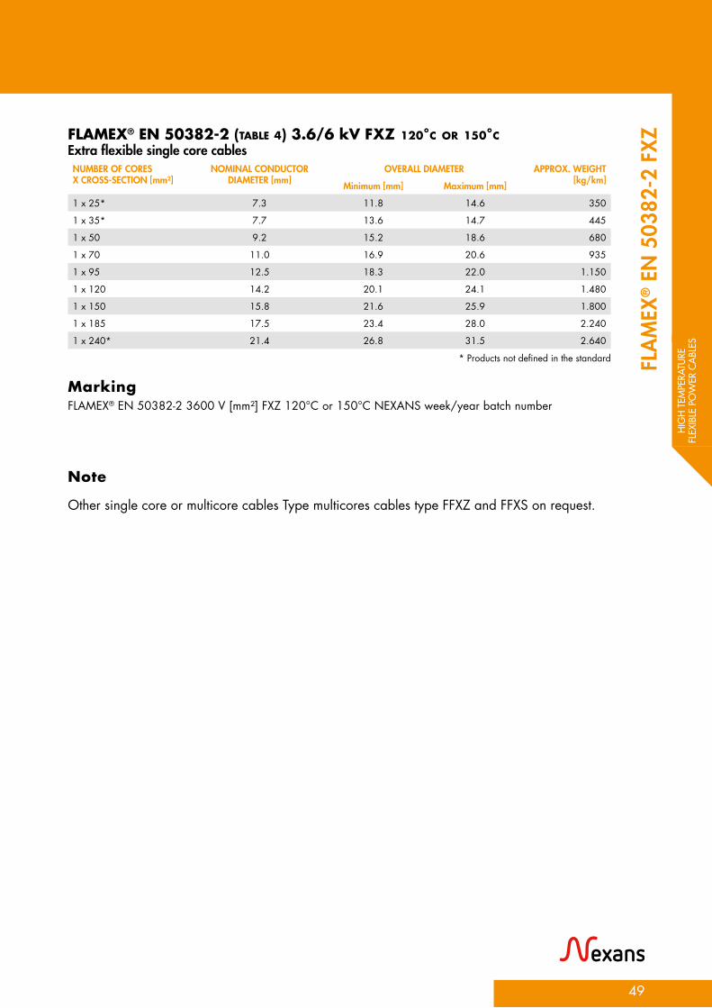
FLAMEX® EN 50382-2 (TABLE 4) 3.6/6 kV FXZ 120°C OR 150°C Extra flexible single core cablesNUMBER OF CORES X CROSS-SECTION [mm²]
NOMINAL CONDUCTOR DIAMETER [mm]
OVERALL DIAMETER APPROX. WEIGHT[kg/km]Minimum [mm] Maximum [mm]
1 x 25* 7.3 11.8 14.6 350
1 x 35* 7.7 13.6 14.7 445
1 x 50 9.2 15.2 18.6 680
1 x 70 11.0 16.9 20.6 935
1 x 95 12.5 18.3 22.0 1.150
1 x 120 14.2 20.1 24.1 1.480
1 x 150 15.8 21.6 25.9 1.800
1 x 185 17.5 23.4 28.0 2.240
1 x 240* 21.4 26.8 31.5 2.640
* Products not defined in the standard FLA
MEX
® E
N 5
0382
-2 F
XZ
FLAMEX® EN 50382-2 3600 V [mm²] FXZ 120°C or 150°C NEXANS week/year batch number
Other single core or multicore cables Type multicores cables type FFXZ and FFXS on request.
Marking
Note

50
HIGH TEMPERATURE FLEXIBLE POWER CABLES
FLAMEX® EN 50382-2 Type FFXS shielded power cables are designed with extra flexible conductors as per jumper cables. They are used for installations where enhanced electrical screening (EMC) is required. Able to withstand higher operating temperatures, these silicone-based cables allow to save cable weight.
APPLICATION
1 ConductorExtra flexible class 6 copper according to IEC 60228 *tinned copper for 120°C Class *plain copper for 150°C Class Separator tape
2 InsulationCross-linked silicone type EI 111 acc. to EN 50382-1.
3 ScreenTinned copper braidSeparator tapes
2 Outer sheathCross-linked silicone type EM 107 acc. to EN 50382-1. Colour: black outer
layer
DESIGN
Static use: 4 x outer diameter (5 x D if D > 12 mm) Dynamic use: 6 x outer diameter
Cabling rules are given in EN 50343. Permissible current carrying capacities comply with EN 50355
BENDING RADIUS
GUIDE TO USE
FLAMEX® EN 50382 cables are conform to EN 45545-2.
FIRE SAFETY STANDARDS
Conductor temperature: -50°C/+120°C/+140°C or -50°C/+150°C/+170°C
Operating temp - 50°C to +120°C- 50°C to +150°C
Low corrosivity of combustion
gasesIEC/EN 60754-2
Low toxicityEN 50305-9.2
Low smokeemission
IEC/EN 61034-2
Halogen-freeIEC/EN 60754-1
IEC 60684-2
Good chemical Resistance
(oil, fuel, acid…)
Flame and Fire retardant
IEC/EN 60332-1-2IEC/EN 60332-3EN 50305-9.1
Good resistance
to UV, humidity
and ozone
High FlexibilityClass 6 + silicone
FLAMEX® EN 50382-2 FFXS 1.8/3 kV or 3.6/6 kVSHIELDED SINGLE CORE POWER CABLE
EMIScreenedversions

HIG
H T
EMPE
RATU
RE
FLEX
IBLE
PO
WER
CA
BLES
51
FLAMEX® EN 50382-2 (TABLE 2) 1.8/3 kV FFXS 120°C OR 150°C Shielded single core cables
CROSS SECTION [mm2]
CONDUCTOR DIAM. [mm]
BRAID SECTION [mm2]
MIN.OUTER DIAM. [mm]
MAX.OUTER DIAM. [mm]
APPROX. WEIGHT [kg/km]
1 x 70 11.4 8.5 18.3 20.6 865
1 x 95 12.9 8.5 20.5 23.1 1.170
1 x 120 14.4 10 22.1 24.9 1.386
1 x 150 17.1 11 24.7 27.8 1.726
1 x 185 18.3 12 26.4 29.4 2.018
FLAMEX® EN 50382-2 (TABLE 5) 3.6/6 kV FFXS 120°C OR 150°C Shielded single core cables
CROSS SECTION [mm2]
CONDUCTOR DIAM. [mm]
BRAID SECTION [mm2]
MIN.OUTER DIAM. [mm]
MAX.OUTER DIAM. [mm]
APPROX.WEIGHT [kg/km]
1 x 70 11.4 13 21.0 23.5 1.000
1 x 95 12.9 15 22.5 25.3 1.286
1 x 120 14.4 16 23.9 26.9 1.461
1 x 150 17.1 16.5 26.7 30.0 1.868
1 x 185 18.3 19 28.6 32.2 2.186
FLA
MEX
® E
N 5
0382
-2 F
FXS
FLAMEX® EN 50382-2 1800 V [mm²] FFXS 120°C or 150°C NEXANS week/year batch number
FLAMEX® EN 50382-2 3600 V [mm²] FFXS 120°C or 150°C NEXANS week/year batch number
Marking
Marking

52

COMMUNICATION CABLESFLAMEX® ETHERNET, WTB, MVB, CAN BUS ................................................. 56
FLAMEX® OPTICAL FIBER CABLES ................................................................ 60
FLAMEX® LOW LOSS COAXIAL ................................................................... 62
FLAMEX® KX/RG COAXIAL......................................................................... 64
COM
MU
NIC
ATIO
N
CABL
ES
53

APPLICATIONSThis range of products meets the current needs of the market especially regarding the interoperability of trains and railway equipment throughout Europe (ERTMS).These cables are adapted for data transmission up to 1 GHz, with performance of Category 7A cables.Nexans experience in the design of shielding technology enables us to propose all constructions with high EMC protection.
ADVANTAGES• Nexans develops halogen-free communication
cables for higher transmission performances to address emerging applications: easy to pool, quick to connect and compatible with standard connectors, and designed to improve the protection against electrical disturbances, electromagnetic noises.
• All these features make FLAMEX® cables the best candidate for new builts and retrofit works.
FLAMEX® - Multimedia & Data transmission cablesHigh transmission performances
MAIN CHARACTERISTICSConnector compatibility Our cables are compatible with most available connectors for rolling stock, field RJ 45, shielded and M 12 connectors.Supported Protocols • WTB (Wire Train Bus):
- connectivity between coaches, Plug & Play concept, - coaches can be coupled and uncoupled while in service
• MVB (Multifunction Vehicle Bus): - connectivity within one car, - can be used within a set of cars MVB & WTB are a part of the TCN protocol defined in the IEC 61375
• PROFIBUS• ETHERNET 100 Ω base T
video on request, audio…
STANDARDS• FLAMEX® communication
cables are conform to EN 45545-2. On top some cables are designed to withstand fire tests according to NFPA 130 and GOST-R 31565
MAIN PROPERTIES• Low smoke emission
according to IEC/EN 61034-2
• Low toxicity (ITC<3) and corrosivity of evolved gases after burning: - Halogen-free content according to IEC/EN 60754-1 - pH > 4.3 according to IEC 60754-2 - Conductivity < 100 μS/cm to IEC/EN 60754-2
• High mechanical resistance (against abrasion, notch propagation and cut through): no additional protection required
• Excellent chemical resistance (against acid,
54
COMMUNICATION CABLES

COM
MU
NIC
ATIO
N
CABL
ES
55

Multimedia & Data Transmission cables for on-board railway equipment. Using the FLAMEX® technology, these halogen-free cables are intended for applications where flame retardancy is required.
APPLICATION
1 ConductorFlexible stranded tinner copper in metric or American wire gauge (AWG) sizes
2 InsulationSpecial halogen-free polyolefin for demanding data transmission
3 ScreenTinner copper braidOptional aluminum/polyester or separator tapes
4 SheathCross-linked compound type EM 104 or EM 101 acc. to EN 50264-1Oil, ozone and UV resistant
DESIGN
Static use: 6 x outer diameter
Our cables are compatible with most available connectors for rolling stock:- ‘Field RJ 45’ connectors- Shielded connectors- M 12 connectors
BENDING RADIUS
CONNECTOR COMPATIBILITY
FLAMEX® communication cables are conform to EN 45545-2. On top some cables are designed to withstand fire tests according to NFPA 130 and GOST-R 31565
FIRE SAFETY STANDARDS
Customized products - 100 Ω to 150 Ω
EMIOperating temp-25°C to +85°C-40°C to +85°C
Low corrosivity of combustion
gasesIEC/EN 60754-2
Low toxicityEN 50305-9.2
Low smokeemission
IEC/EN 61034-2
Halogen-freeIEC/EN 60754-1
IEC 60684-2
FlexibleGood chemical Resistance
(oil, fuel, acid…)
Screenedversions
Flame and Fire retardant
IEC/EN 60332-1-2IEC/EN 60332-3
56
COMMUNICATION CABLES
MULTIMEDIA & DATA TRANSMISSION CABLES ON-BOARD EQUIPMENT

COM
MU
NIC
ATIO
N
CABL
ES
57
MU
LTIM
EDIA
& D
ATA
TRA
NSM
ISSI
ON
CA
BLESETHERNET CABLES 100 Ω
NEXANS REF.
DEDICATED NETWORK
CONSTRUCTION [n × mm² or AWG]
SCREEN NOMINAL DIAMETER
[mm]
APPROX. WEIGHT [kg/km]
COLOR CODING CORES
COLOR OF THE SHEATH
LOW TEMP.
2PM617 CAT 7A 4 × (2 × 0,25²) I+S 8.5 85 A Blue -40°C
2PM615 CAT 7 4 × (2 × 0,25²) I+S 8.5 82 A Blue -40°C
2PM622 CAT 7 4 × (2 × AWG 24/7) I+S 8.1 71 A Black -40°C
2PM697 CAT7 4 × (2 × AWG 26/7) I+S 7,1 55 A Black -40°C
45994810 CAT 7 4 × (2 × AWG 24/7) I+S 8.6 97 A Black -40°C
2PM577 CAT 6A 4 × (2 × 0,25²) I+S 8.5 80 A Blue -40°C
2PM578 CAT 6A 4 × (2 × 0,50²) I+S 11.9 147 A Blue -40°C
2PK319 CAT 5E 4 × 0,25² S 6.7 65 C Blue -25°C
2PK699 CAT 5E 4 × 0,25² S 6.7 65 C Blue -40°C
2PM022 CAT 5E 4 × AWG 22/7 (0,34²) S 6.5 62 C Blue -25°C
2PG229 CAT 5E 4 × AWG 22/7 (0,34²) S 6.5 62 D Black -25°C
2PM676 CAT 5E 4 × AWG 22/7 (0,34²) S 6.5 62 C Blue -40°C
2PK847 CAT 5E 4 × AWG 22/7 (0,34²) S 6.5 62 D Black -40°C
45993310 CAT 5E 4 × AWG 22/19 (0,34²) S 6.9 74 C Black -40°C
45994010 CAT 5E 4 × AWG 22/7 (0,34²) S 7.2 77 C Black -40°C
2PK211 CAT 5E 4 × 0,50² S 8.5 96 C Blue -25°C
2PK698 CAT 5E 4 × 0,50² S 8.5 96 C Blue -40°C
45923010 CAT 5E 4 x AWG 20/19 S 7.8 96 D Black -40°C
2PC912 CAT 5E 2 × (2 × 0,25²) S 6.5 55 A Black -25°C
2PK592 CAT 5E 2 × (2 × 0,50²) S 9.7 120 B Black -25°C
2PH934 CAT 5E 2 × (2 × 0,50²) S 9.8 118 B Black -25°C
2PI232 CAT 5E 2 × (2 × 0,50²) S 9.7 120 B Black -40°C
2PF146 CAT 5E 4 × 0,60² S 7.8 86 C Black -25°C
S: Outer screen made of aluminium foil + tinned copper braidI+S: Individual screen made of aluminium foil + general tinned copper braid
A: Color coding for pairs: N°1: white + blue N°2: white + orange N°3: white + green N°4: white + brown
B: Color coding for pairs: N°1: white + blue N°2: yellow + orange
C: Color coding for quads: N°1: white + blue N°2: yellow + orange
D: Color coding for quads: N°1: white + yellow N°2: red + black
E: Color coding for quads: N°1: white/orange + orange N°2: white/blue + blue

WIRE TRAIN BUS & MULTIFUNCTION VEHICLE BUS 120 Ω
NEXANS REF.
DEDICATED NETWORK
CONSTRUCTION [n × mm² or AWG]
NOMINAL DIAMETER
[mm]
APPROX. WEIGHT [kg/km]
COLOR CODING CORES
COLOR OF THE SHEATH
LOW TEMP.
2PK595 WTB 2 x 0,75² 8.5 92 F Turquoise -25°C
2PF578 WTB 2x 0,75² 8.2 87 F Black -40°C
45983010 WTB 2 x AWG 20/19 7.9 83 F Black -40°C
2PE993 MVB 4 × 0,50² 8.0 86 D Turquoise -25°C
2PK697 MVB 4 × 0,50² 8.0 86 D Turquoise -40°C
45953050 MVB 4 × 0,50² 8.0 90 D Turquoise -40°C
2PK596 MVB 2 × 0,50² 8.0 84 F Turquoise -25°C
2PF580 MVB 2 × 0,50² 8.0 84 F Turquoise -40°C
45903050 MVB 4 x AWG 20/19 7.9 91 D Turquoise -40°C
PROFIBUS & CAN BUS
NEXANS REF.
DEDICATED NETWORK
CONSTRUCTION [n × mm² or AWG]
NOMINAL DIAMETER
[mm]
APPROX. WEIGHT [kg/km]
COLOR CODING CORES
COLOR OF THE SHEATH
LOW TEMP.
2PF164 PROFIBUS 2 × 0,34² 8.0 82 G Purple -25°C
2PJ623 PROFIBUS 2 × 0,34² 8.0 82 G Purple -40°C
2PK478 CAN BUS 2 × 0,50² + 1 x 0,50² 8.5 70 H Black -25°C
2PF860 CAN BUS 2 × 0,50² + 1 x 0,50² 6.8 62 H Black -25°C
2PI096 CAN BUS 2 × 0,50² + 1 x 0,50² 6.8 62 H Black -40°C
45984710 CAN BUS 2 × 0,50² + 1 x 0,50² 7,1 71 H Black -40°C
58
MULTIMEDIA & DATA TRANSMISSION CABLES ON-BOARD EQUIPMENT

COM
MU
NIC
ATIO
N
CABL
ES
59
MU
LTIM
EDIA
& D
ATA
TRA
NSM
ISSI
ON
CA
BLES

60
COMMUNICATION CABLES
FLAMEX® OPTICAL FIBER CABLESHALOGEN-FREE MONO AND MULTI-FIBERS
EMIOperating temp
- 40°C to +80°C
Low corrosivity of combustion
gasesIEC/EN 60754-2
Low toxicityEN 50305-9.2
Low smokeemission
IEC/EN 61034-2
Halogen-freeIEC/EN 60754-1
IEC 60684-2
FlexibleClass 5
Good chemical Resistance
(oil, fuel, acid…)
Flame and
Fire retardantIEC/EN 60332-1-2IEC/EN 60332-3EN 50305-9.1
Screenedversion
Nexans produces a range of optical fiber cables for onboard communication and data transmission. With a FLAMEX® halogen-free insulation and a FLAMEX® halogen-free jacket, they conform to the rolling stock requirements.
APPLICATION
OPTICAL FIBER OM1 (62.5/125 μm) and OM3 (50/125 μm)
DESIGN
FLAMEX® optical fiber cables are conform to EN 45545-2. On top some cables are designed to withstand fire tests according to NFPA 130 and GOST-R 31565
FIRE SAFETY STANDARDS
Example: FLAMEX P/Number Nexans - number of fiber x 62.5/125 - month and year of production
MARKING
1 Patch cordCore: glass OM 1 or 0M 3 Diameter = 62.5 or 50μmCladding: glass Diameter = 125 ± 3 μmCoating: acrylate Diameter = 245 ± 10 μmBuffer: Thermoplastic elastomer Diameter = 900 ± 50 μmReinforcement: Aramid yarnsSheath: Halogen-free FLAMEX® according to EN 50264-1 type EM 104 Diameter = 2.00 ± 0.15 mm
2 Tape (for multi-fibers)
3 Outer sheathCross-linked halogen-free FLAMEX® according to EN 50264-1 type EM 104
Multi-fibers
Single fiber

COM
MU
NIC
ATIO
N
CABL
ES
61
OPT
ICA
L FI
BER
CABL
ESOM1 (62.5/125μm) multi-mode fiber cables
PHYSICAL & MECHANICALCHARACTERISTICS
2PH526 2PH527 2PH528 2PH529 2PH530
Number of fibers 1 2 4 6 8
Cable diameter [mm] 2.0 6.0 7.0 8.0 8.5
Approx. weight [kg/km] 6 20 40 60 80
Max. loading (IEC 60794-1)
Static [N] 250 500 1000 1500 2000
Dynamic [N] 125 250 500 750 1000
Mini. bending radius (IEC 60794-1)
Static [mm] 20 60 70 80 85
Dynamic [mm] 40 120 140 160 170
Crush resistance (IEC 60974-1) 250 N/cm
ATTENUATION VALUE UNIT
850 nm (cabled) ≤ 3.5 dB/Km
1300 nm (cabled) ≤ 1.5 dB/Km
OM3 (50/125μm) multi-mode fiber cables
PHYSICAL & MECHANICALCHARACTERISTICS
2PH550 2PH551 2PH552 2PH553
Number of fibers 2 4 6 8
Cable diameter [mm] 7.0 7.0 8.0 8.5
Approx. weight [kg/km] 40 40 60 80
Max. loading (IEC 60794-1)
Static [N] 500 1000 1500 2000
Dynamic [N] 250 500 750 1000
Mini. bending radius (IEC 60794-1)
Static [mm] 60 70 80 85
Dynamic [mm] 120 140 160 170
Crush resistance (IEC 60974-1) 250 N/cm
ATTENUATION VALUE UNIT
850 nm (cabled) ≤ 3.0 dB/Km
1300 nm (cabled) ≤ 1.0 dB/Km

62
COMMUNICATION CABLES
FLAMEX® LLClow loss coaxial cables
FLAMEX® LLC are intended for antenna wireless communication systems. This product range offers superior RF shielding effectiveness.
APPLICATION
Coaxial cables 50 Ω
DESIGN
FLAMEX® LLC cables are conform to EN 45545-2. The cables are also designed to withstand fire tests according to NFPA 130
Compatible with all standard coaxial connectors
FIRE SAFETY STANDARDS
CONNECTORS
Example: FLAMEX ANTENNA COAXIAL 50 OHMS LOW LOSS 240 - NEXANS 239 – EDE 2PM719 - ** **** ** : Week and year
MARKING
1 ConductorBare copper
2 Insulation Foam polyethylene
3 ScreenAluminium/polyester tapeTinned copper braidSeparator tape
4 Outer sheath Cross-linked material EM 104 acc. EN 50264-1 Oil, diesel, ozone and UV resistant Colour: black
Operating temp-40°C to +85°C
Low corrosivity of combustion
gasesIEC/EN 60754-2
Low toxicityEN 50305-9.2
Low smokeemission
IEC/EN 61034-2
Halogen-freeIEC/EN 60754-1
IEC 60684-2
Good chemical Resistance
(oil, fuel, acid…)
EMIScreenedversions
Flame and Fire retardant
IEC/EN 60332-1-2IEC/EN 60332-3

COM
MU
NIC
ATIO
N
CABL
ES
63
OPT
ICA
L FI
BER
CABL
ESLow Loss Coaxial Cables 50 Ω
PHYSICAL & MECHANICAL CHARACTERISTICS LLC 2402PM719
LLC 4002PM720
Cable diameter [mm] 6.10 ± 0.20 10.30 ± 0.20
Approx. weight [kg/km] 60 170
Bending radius [mm] 60 > 100
ELECTRICAL CHARACTERISTICS LLC 2402PM719
LLC 4002PM720
Inner conductor resistance at 20 °C [W/km] 11.2 3.4
Outer conductor resistance at 20 °C [W/km] 12.4 5.4
Propagation velocity [%] 80 80
Capacitance [pF/m] 78 78
Screening attenuation up to 6GHZ [dB] * 80 * 90
Nominal structural return loss [dB]
5 - 470 MHz 28 28
470 - 1000 MHz 26 26
1000 - 2000 MHz 24 24
2000 - 3000 MHz 20 20
Attenuation [dB/100 m at frequency]
450 MHz 17,2 8,7
500 MHz 24,3 12,5
1500 MHz 32,7 16,6
1800 MHz 35,9 18,2
2000 MHz 37,9 19,3
2500 MHz 42,3 21,5
5800 MHz 66,5 34,4
6000 MHz 69,0 35,0

64
COMMUNICATION CABLES
Nexans produces a range of coaxial cables for data transmission and video signal in onboard equipment.
APPLICATION
Coaxial cables 50 Ω and 75 Ω
FLAMEX® KX/RGCOAXIAL CABLES
EMIOperating temp
- 30°C to +80°C
Low corrosivity of combustion
gasesIEC/EN 60754-2
Low toxicityEN 50305-9.2
Low smokeemission
IEC/EN 61034-2
Halogen-freeIEC/EN 60754-1
IEC 60684-2
FlexibleGood chemical Resistance
(oil, fuel, acid…)
Flame and Fire retardant
IEC/EN 60332-1-2IEC/EN 60332-3EN 50305-9.1
DESIGN
Static use: 5 x outer diameter
Compatible with standard connectors: SMA, SMB, TNC, BNC, N...
BENDING RADIUS
CONNECTORS
MIL C 17 (RG) - NF C 93 550 (KX)
STANDARDS
«FLAMEX® RG x XX» (cable type) in white marking
MARKING
1 ConductorStranded bare, tinned or silver coated copper
2 DielectricPE
3 ScreenSingle or double braid in bare, tinned or silver coated copper
4 SheathHalogen-freeColour: blackOptional lay up with fire barrier tapes

COM
MU
NIC
ATIO
N
CABL
ES
65
FLA
MEX
® K
X/RG
COAXIAL CABLES 50 Ω
DESIGNATION NEXANS CONDUCTOR DIELECTRIC BRAID CABLE RATEDVOLTAGE
[V ac]Stranding* Diameter[mm]
Diameter[mm]
Ext. diam. [mm]
Weight[kg/km]
FLAMEX® KX15 / RG58 2PM711 19 x 0.18 0.90 2.95 ± 0.10 Single braid 4.95 ± 0.10 45 1400
FLAMEX® KX15-2S 2PM712 19 x 0.18 0.90 2.95 ± 0.10 Double braid 5.38±0.10 50 1400
FLAMEX® KX4 / RG213 2PM708 7 x 0.75 2.25 7.25 ± 0.15 Single braid 10.30 ± 0.20 160 3700
FLAMEX® KX13 / RG214 2PJ749 7 x 0.75 2.25 7.25 ± 0.15 Double braid 10.80 ± 0.20 205 3700
Capacity: < 106 pF/m - Velocity of propagation: 65.9%
COAXIAL CABLES 75 Ω
DESIGNATION NEXANSREFERENCE
CONDUCTOR DIELECTRIC BRAID CABLE RATEDVOLTAGE
[V ac]Stranding* Diameter[mm]
Diameter[mm]
Ext. diam. [mm]
Weight[kg/km]
FLAMEX® KX6A / RG59 2PM709 7 x 0.20 0.60 3.70 ± 0.12 Single braid 6.10 ± 0.15 57 1700
FLAMEX® KX8 / RG11 2PM710 7 x 0.40 1.20 7.25 ± 0.15 Single braid 10.30 ± 0.20 122 3700
Capacity: < 72.2 pF/m - Velocity of propagation: 65.9%
COAXIAL CABLES 95 Ω
DESIGNATION NEXANSREFERENCE
CONDUCTOR DIELECTRIC BRAID CABLE RATEDVOLTAGE
[V ac]Stranding* Diameter[mm]
Diameter[mm]
Ext. diam. [mm]
Weight[kg/km]
FLAMEX® RG022 2PM713 7 x 0.40 1.20 7.24±0.15 Double braid 10.70±0.25 200 -
ATTENUATION VALUES
DESIGNATION ATTENUATION AT X MHz [dB/100m](nominal values)
50 100 200 400 1000 3000 11000
50 Ω
FLAMEX® KX15 / RG58 13.1 21.3 55.8 91.9
FLAMEX® KX4 / RG213 3.9 7.5 15.7 29.5
FLAMEX® KX13 / RG214 5.6 22.3 91.9 196.9
75 Ω FLAMEX® KX6A / RG59 20
FLAMEX® KX8 / RG11 20 17.1 30.8

66

FIRE RESISTANT CABLESFLAMEX® RANGE: EN 50200 .................................................................... 68
FLAMEX® MSZ ......................................................................................... 70
FLAMEX® (N)MHXAF-FR TYPE EN 50264-3-1 ................................................. 76
FLAMEX® 4GKW–FR / HXAFOE-FR .............................................................. 78
FLAMEX® SI-FR TYPE EN 50382-2 F & FX ...................................................... 80
FLAMEX® FR ETHERNET ............................................................................ 82
FIRE
RES
ISTA
NT
CABL
ES
67

APPLICATIONS• Cables are everywhere around us and most
of the time not visible once they are installed. However, in the event of fire, rolling stock equipment should remain functional to help in the evacuation process.
• Fire resistant cables are designed to be used in safety systems (emergency lighting, fire detection, warning systems, door opening, etc.) for control or power feeding.
The European directive for interoperability Loc & Pass 1302/2014/EU dated of November 18th 2018 and EN 45545-1 require that in case of fire on board the emergency lighting shall continue to operate at minimum to 50 % in the coaches where there is no fire detected: • Evaluation of the availability for breaking for at
least 4 minutes for category A• Evaluation of the availability for breaking
and power traction for at least 15 minutes for category BADVANTAGES
• Nexans is dedicated to improve safety in rolling stock by protecting people’s lives and trail from fires with innovative fire safety cables. These cables ensure the integrity of electrical circuits for a certain time after the fire started.
FLAMEX® - EN 50200Fire resistant cables
MAIN CHARACTERISTICS• Voltage rate:
- 300/500 V - 0.6/1kV - 1.8/3kV
• Single core and multicore (unshielded or shielded) power and control cables
STANDARDS AND SPECIFICATIONS• Fire resistance acc. to:
- EN 50200 - IEC 60331 -1 & -2
• FLAMEX® fire resistant cables are conform to EN 45545-2. On top of that the cables are designed to withstand fire tests according to NFPA 130 and GOST-R 31565
MAIN PROPERTIES• Low smoke emission
according to IEC 61034-2• Low toxicity (ITC<3) and
corrosivity of evolved gases after burning: - Halogen-free content according to IEC/EN 60754-1 - pH > 4.3 according to IEC/EN 60754-2 - Conductivity < 100 μS/cm to IEC/EN 60754-2
• High mechanical resistance (against abrasion, tensile strength and cut through): no additional protection required
• Excellent chemical resistance (against acid, alkali, oil, fuel…)
68
FIRE RESISTANT CABLES

FIRE
RES
ISTA
NT
CABL
ES
69

70
FIRE RESISTANT CABLES
FLAMEX® MSZ flexible control cables maintain circuit integrity in case of fire (according to EN 50200 for 90 minutes) and are fire retardant, low smoke and halogen-free satisfying performance requirements from EN 45545-2.On top of that, FLAMEX® cables withstand tough working conditions (oil, ozone, temperature variation, etc.).
APPLICATION
Conductor temperature: -40°C/+105°C/+125°C
FLAMEX® MSZ 300/500 VFIRE RESISTANT SINGLE CORE CONTROL CABLE
Operating temp - 40°C to +105°C
Low corrosivity of combustion
gasesIEC/EN 60754-2
Low toxicityEN 50305-9.2
Low smoke emission
IEC/EN 61034-2
Halogen-freeIEC/EN 60754-1
IEC 60684-2
FlexibleGood chemical Resistance
(oil, fuel, acid…)
Flame and Fire
retardantIEC/EN 60332-1-2IEC/EN 60332-3EN 50305-9.1
Fire resistantEN 50200
DESIGN
Static use: 2 x outer diameterDynamic use: 3 x outer diameter
Permissible current capacities and cabling rules given in EN 50355 and EN 50343
White
BENDING RADIUS
GUIDE TO USE
CORE COLOURS
FLAMEX® MSZ are conform to EN 45545-2 and GOST-R 31565. Fire resistant acc. to:EN 50200 - 90 minIEC 60331-2 - 90 minIEC 60331-21 - 120 min
FIRE SAFETY STANDARDS
With reference to EN 50306-2
1 ConductorFlexible stranded tinned copper according to EN 50306
2 InsulationMica tape as fire barrier and halogen-free cross-linked material acc. to EN 50306-2Color: light grey

FIRE
RES
ISTA
NT
CABL
ES
71
FLA
MEX
® M
SZ T
YPE
EN 5
0306
-2
X NEXANS X FLAMEX® MSZ 300 V 1x section M Marking
FLAMEX® MSZ TYPE EN 50306-2 SINGLE CORE
NEXANSREFERENCE
NUMBER OF CORES X CROSS-SECTION
[mm²]
CONDUCTOR INSULATION MAX. COND.RESISTANCE[Ohm/km]
APPROX. WEIGHT[kg/km]n x diameter
[mm]Max. diameter
[mm]Min. diam.
[mm]Max. diam.
[mm]
459980xx 1 x 0.5 19 x 0.18 0.95 1.70 2.0 40.1 7.5
459981xx 1 x 0.75 19 x 0.23 1.20 1.90 2.2 26.7 11.0
459982xx 1 x 1.0 19 x 0.25 1.40 2.00 2.3 20.0 14.0
459983xx 1 x 1.5 19 x 0.30 1.60 2.50 2.9 13.7 19.0
459984xx 1 x 2.5 19 x 0.39 2.10 2.90 3.3 8.21 29.0
xx: 27 for spools and 29 for barrels
PHYSICAL PROPERTIES REQUIREMENTS
Max. tensile strength under permeation 50 N/mm2 conductor cross-section
Static tensile strength and fixed laying 15 N/mm2 conductor cross-section

72
FLAMEX® MSZ 300 /500 VFIRE RESISTANT MULTICORE CONTROL CABLE CLASS P
EMILow smokeemission
IEC/EN 61034-2
Good chemical Resistance
(oil, fuel, acid…)
Flame and Fire
retardantIEC/EN 60332-1-2IEC/EN 60332-3EN 50305-9.1
FLAMEX® MSZ flexible multicore control cables maintain circuit integrity in case of fire (according to EN 50200 for 90 minutes) and are fire retardant, low smoke and halogen-free complying performance requirements from EN 45545-2.On top of that, FLAMEX® cables withstand tough working conditions (oil, ozone, temperature variation, etc.). MSZ cable range is designed with thin jacket thickness for protected environment.This cable is neither useful for multiple bending nor for torsion.
APPLICATION
Conductor temperature: -40°C/+90°C / +110°C
DESIGN
Static use: 3xD for unscreened(5xD for screened types)Dynamic use: 5xD for unscreened(10xD for screened types)
With reference to EN 50306-2
Permissible current capacities and cabling rules given in EN 50355 and EN 50343
Up to 10 cores colored :Core 1: whiteCore 2: brownCore 3: blueCore 4: blackCore 5: redCore 6: yellowCore 7: greenCore 8: greyCore 9: orangeCore 10: violet> 10 cores: all cores black with numbers
BENDING RADIUS
GUIDE TO USE
CORE COLOURS
FLAMEX® MSZ cables are conform to EN 45545-2. On top of that the cables are designed to withstand fire tests according to GOST-R 31565 Fire resistant acc. to:EN 50200 - 90 minIEC 60331-2 - 90 minIEC 60331-21 - 120 min
FIRE SAFETY STANDARDS
1 ConductorFlexible stranded tinned copper according to EN 50306
2 InsulationMica tape as fire barrier, halogen-free flame retardant cross-linked material EI 102 acc. to EN 50264-1
3 Screening (Optional)Tinned copper braiding, optical coverage approx. 85 %. Optional separator
4 Outer sheathCross-linked compound type EM 104, acc. to. EN 50264-1Colour: black
FIRE RESISTANT CABLES
Fire resistant
Operating temp - 40°C to +105°C
Low corrosivity of combustion
gasesIEC/EN 60754-2
Low toxicityEN 50305-9.2
Halogen-freeIEC/EN 60754-1
EIEC 60684-2
Flexible Screened version

FIRE
RES
ISTA
NT
CABL
ES
73
FLA
MEX
® M
SZMSZ UNSCREENED MULTICORE NEXANSREFERENCE
NUMBER OF CORES X CROSS-SECTION
[mm²]
INSULATION OUTER DIAMETER APPROX. WEIGHT[kg/km]Min. diam. [mm] Max. diam. [mm] Minimum [mm] Maximum [mm]
45985910 2 x 1.00 1.95 2.15 5.3 5.9 52
45986410 14 x 1.00 1.95 2.15 10.7 11.5 225
45986210 2 x 1.50 2.20 2.50 6.0 7.0 69
41395610 6 x 1.50 2.20 2.50 8.7 9.5 154
45986710 7 x 1.50 2.20 2.50 9.3 10.3 187
45988510 25 x 1.50 2.20 2.50 17.4 19.0 604
45987210 2 x 2.50 2.75 3.05 7.4 8.2 99
45987810 8 x 2.50 2.75 3.05 12.4 13.4 318
45988610 25 x 2.50 2.75 3.05 20.5 22.3 910
MSZ UNSCREENED MULTICORE WITH ONE CORE GREEN/YELLOW
NEXANSREFERENCE
NUMBER OF CORES X CROSS-SECTION
[mm²]
INSULATION OUTER DIAMETER APPROX. WEIGHT[kg/km]Min. diam. [mm] Max. diam. [mm] Minimum [mm] Maximum [mm]
41375510 5 x 1.50 2.20 2.50 8.0 8.6 131
41375710 7 x 1.50 2.20 2.50 9.3 10.3 187
41375110 12 x 1.50 2.20 2.50 11.3 12.4 282
41375910 25 x 1.50 2.20 2.50 17.4 19.2 612
41376310 3 x 2.50 2.75 3.05 7.9 8.5 131
41376810 12 x 2.50 2.75 3.05 14.3 15.4 437
41376910 25 x 2.50 2.75 3.05 20.5 22.3 914
Other designs on request.

74
FLAMEX® MSZ 300 /500 VFIRE RESISTANT MULTICORE CONTROL CABLE CLASS P
X NEXANS X FLAMEX 2 MSZ 0.5 C HXOE MMMarking
MSZ SCREENED MULTICORE NEXANSREFERENCE
NUMBER OF CORES X CROSS-SECTION
[mm²]
INSULATION OUTER DIAMETER APPROX. WEIGHT[kg/km]Min. diam. [mm] Max. diam. [mm] Minimum [mm] Maximum [mm]
41392110 2 x 0.50 1.60 1.80 5.4 6.0 53
41392310 3 x 0.50 1.60 1.80 5.7 6.4 62
41392410 4 x 0.50 1.60 1.80 6.1 6.8 71
41382110 10 x 0.50 1.60 1.80 9.0 9.7 145
45988210 2 x 0.75 1.80 2.00 5.5 6.3 63
4598 8710 3 x 0.75 1.80 2.00 6.0 6.6 72
45988310 4 x 0.75 1.80 2.00 6.2 7.0 83
41383610 6 x 0.75 1.80 2.00 8.0 8.6 124
45988010 2 x 1.00 1.95 2.15 5.8 6.4 66
41394410 4 x 1.00 1.95 2.15 7.0 7.6 96
45988110 6 x 1.00 1.95 2.15 8.4 9.0 139
41385210 2 x 1.50 2.20 2.50 6.6 7.2 84
45988410 14 x 1.50 2.20 2.50 12.7 13.7 350
45989010 2 x 2.50 2.75 3.05 7.9 8.7 124
45988810 8 x 2.50 2.75 3.05 13.0 14.0 352
MSZ SCREENED MULTIPAIRS
NEXANSREFERENCE
NUMBER OF CORES X CROSS-SECTION
[mm²]
INSULATION OUTER DIAMETER APPROX. WEIGHT[kg/km]Min. diam. [mm] Max. diam. [mm] Minimum [mm] Maximum [mm]
45986910 7 x 2 x 0.5 1.60 1.80 11.6 13.5 220
45987010 6 x 2 x 0.75 1.80 2.00 12.6 14.0 247
45986610 3 x 2 x 1.00 2.20 2.50 10.3 11.3 174
45987110 2 x 2 x 1.5 2.20 2.50 11.2 12.3 206
45986510 7 x 2 x 1.5 2.20 2.50 15.6 17.2 421

FIRE
RES
ISTA
NT
CABL
ES
75
FLA
MEX
® M
SZ

76
FIRE RESISTANT CABLES
FLAMEX® (N)MHXAF-FR type EN 50264-3-1 0.6/1 kVFIRE RESISTANT SINGLE CORE POWER CABLE
FLAMEX® (N)MHXAF-FR flexible power cables maintain circuit integrity in case of fire (according to EN 50200 for 120 minutes) and are fire retardant, low smoke and halogen-free satisfying performance requirements from EN 45545-2.On top of that, FLAMEX® cables are designed to withstand tough working conditions (oil, ozone, temperature variation, etc.).
APPLICATION
Conductor temperature: -40°C/+90°C/+120°C
DESIGN
Static use: 3 x outer diameter(5 x D if D > 10mm)Dynamic use: 10 x outer diameter
Permissible current capacities and cabling rules given in EN 50355 and EN 50343
BENDING RADIUS
GUIDE TO USE
FLAMEX® (N)MHXAF-FR cables are conform to EN 45545-2. On top of that, the cables are designed to withstand fire tests according to GOST-R 31565. Fire resistant acc. to:EN 50200 - 120 minIEC 60331-2 - 120 minIEC 60331-1 - 120 min
FIRE SAFETY STANDARDS
In line with EN 50264-3-1
1 ConductorFlexible stranded tinned copper class 5 according to IEC/EN 60228
2 InsulationMica tape as fire barrier and cross-linked compound type EI 109 according to EN 50264-1Oil, diesel, ozone and UV resistantColour: black
Fire resistant
Operating temp - 40°C to +90°C
Low corrosivity of combustion
gasesIEC/EN 60754-2
Low smokeemission
IEC/EN 61034-2
Halogen-freeIEC/EN 60754-1
IEC 60684-2
Good chemical Resistance
(oil, fuel, acid…)
Flame and Fire
retardantIEC/EN 60332-1-2IEC/EN 60332-3EN 50305-9.1
Good resistance
to UV, humidity
and ozone
Low toxicityEN 50305-9.2
FlexibleClass 5

FIRE
RES
ISTA
NT
CABL
ES
77
FLA
MEX
® (N
)MH
XAF-
FR T
YPE
EN 5
0264
-3-1
FLAMEX® type EN 50264-3-1 FR 600 V section M (N)MHXAF-FR 0,6/1 kV | NEXANS | week/year batch number
Marking
FLAMEX® (N)MHXAF-FR TYPE EN 50264-3-1 0.6/1 kV M Fire Resistant single core NEXANSREFERENCE
NUMBER OF CORES X CROSS-SECTION [mm²]
OVERALL DIAMETER APPROX. WEIGHT[kg/km]Minimum [mm] Maximum [mm]
7946 2214 1 x 1 3.1 3.3 18
7946 2314 1 x 1.5 3.4 3.8 24
7946 2414 1 x 2.5 3.8 4.2 33
7946 2514 1 x 4 4.5 4.9 46
7946 2614 1 x 6 5.0 5.4 66
7946 2714 1 x 10 6.1 6.5 110
7946 2814 1 x 16 7.1 7.7 170
7946 2914 1 x 25 8.7 9.3 255
7946 3014 1 x 35 9.8 10.4 340
7946 3114 1 x 50 11.9 12.5 490
7946 3214 1 x 70 13.8 14.4 700
7946 3314 1 x 95 15.3 15.9 900

78
FIRE RESISTANT CABLES
FLAMEX® 4GKW-FR / HXAFOE-FR type EN 50264-3-1 1.8/3 kVFIRE RESISTANT SINGLE CORE POWER CABLE
FLAMEX® 4GKW-FR / HXAFOE-FR flexible control cables maintain circuit integrity in case of fire (according to EN 50200 for 120 minutes) and are fire retardant, low smoke and halogen-free satisfying performance requirements from EN 45545-2. On top of that, FLAMEX® cables are designed to withstand tough working conditions (oil, ozone, temperature variation, etc.).
APPLICATION
Conductor temperature: -40°C/+90°C/+120°C
DESIGNStatic use: 3 x outer diameter(5 x D if D > 10mm)Dynamic use: 10 x outer diameter
Permissible current capacities and cabling rules given in EN 50355 and EN 50343
BENDING RADIUS
GUIDE TO USE
FLAMEX® 4GKW-FR / HXAFOE-FR cables are conform to EN 45545-2. On top of that, the cables are designed to withstand fire tests according to GOST-R 31565. Fire resistant acc. to:EN 50200 - 120 minIEC 60331-2 - 120 minIEC 60331-1 - 120 min
FIRE SAFETY STANDARDS
In line with EN 50264-3-1
1 ConductorFlexible stranded tinned copper class 5 according to IEC/EN 60228
2 InsulationMica tape as fire barrier and cross-linked compound type EI 109 according to EN 50264-1 Oil, diesel, ozone and UV resistantColour: black
Fire resistant
Operating temp - 40°C to +90°C
Low corrosivity of combustion
gasesIEC/EN 60754-2
Low smokeemission
IEC/EN 61034-2
Halogen-freeIEC/EN 60754-1
IEC 60684-2
Good chemical Resistance
(oil, fuel, acid…)
Flame and Fire
retardantIEC/EN 60332-1-2IEC/EN 60332-3EN 50305-9.1
Good resistance
to UV, humidity
and ozone
Low toxicityEN 50305-9.2
FlexibleClass 5

FIRE
RES
ISTA
NT
CABL
ES
79
FLAMEX® 4GKW-FR / HXAFOE-FR type EN 50264-3-1 1.8/3 kVFIRE RESISTANT SINGLE CORE POWER CABLE
FLA
MEX
® 4
GKW
-FR
/ H
XAFO
E-FR
TYP
E EN
502
64-3
-1
FLAMEX® type EN 50264-3-1 FR 1800V 1 x section MM 4GKW-FR HXAFOE-FR 1.8/3 kV | NEXANS | week/year batch number
Marking
FLAMEX® 4GKW-FR HXAFOE-FR TYPE EN 50264-3-1 1.8/3 kV M Fire Resistant single core NEXANSREFERENCE
NUMBER OF CORES X CROSS-SECTION [mm²]
OVERALL DIAMETER APPROX. WEIGHT[kg/km]Minimum [mm] Maximum [mm]
7947 1429 1 x 1 3.30 3.50 15
7947 1430 1 x 1.5 3.70 3.90 21
7947 1431 1 x 2.5 4.15 4.45 33
7947 1432 1 x 4 4.95 5.25 55
7947 1433 1 x 6 5.55 5.85 75
7947 1434 1 x 10 6.80 7.20 115
7947 1435 1 x 16 8.70 9.10 190
7947 1436 1 x 25 10.90 11.50 290
7947 1437 1 x 35 12.00 12.60 400
7947 1438 1 x 50 13.90 14.50 550
7947 1439 1 x 70 15.90 16.50 750
7947 1440 1 x 95 17.60 18.20 970
7947 1441 1 x 120 19.90 20.50 1.250
7947 1442 1 x 150 22.20 22.80 1.550
7947 1443 1 x 185 24.10 24.70 1.900
7947 1444 1 x 240 27.20 27.80 2.450

80
FIRE RESISTANT CABLES
FLAMEX® SI-FR type EN 50382-2 F & FX 1.8/3 kV & 3.6/6 kVFIRE RESISTANT HIGH TEMPERATURE FLEXIBLE POWER CABLE
FLAMEX® SI-FR EN 50382-2 power cables maintain circuit integrity in case of fire (according to IEC 60331-4 for 90 minutes) and are fire retardant, low smoke and halogen-free satisfying performance requirements form EN 45545-2. Theses cables can withstand harsh operation conditions on rolling stock (variations in temperature, snow, rain, sunlight, heavy vibrations, etc...). FLAMEX® SI-FR EN 50382-2 is suitable for weight saving and cabling operation in narrow spaces.
APPLICATION
Conductor temperature: -50°C/+120°C/+140°C or -50°C/+150°C/+170°C
DESIGN
Static use:4 x outer diameterDynamic use:6 x outer diameter
Permissible current capacities and cabling rules given in EN 50355 and EN 50343
BENDING RADIUS
GUIDE TO USE
FLAMEX® SI-FR EN 50382-2 cables are conform to EN 45545-2. Fire resistant acc. to: IEC 60331-4 - 90 min
FIRE SAFETY STANDARDS
In line with EN 50264-3-1
1 ConductorFlexible class 5 or 6 copper according to IEC 60228- Tinned copper for 120°C Class
- Plain copper for 150°C Class
2 InsulationFire barrier and cross-linked silicone compound type EI 111 according to EN50382-1Colour: black
Fire resistant
Operating temp - 50°C to +120°C- 50°C to +150°C
Low corrosivity of combustion
gasesIEC/EN 60754-2
Low toxicityEN 50305-9.2
Low smokeemission
IEC/EN 61034-2
Halogen-freeIEC/EN 60754-1
IEC 60684-2
Good chemical Resistance
(oil, fuel, acid…)
Flame and Fire
retardantIEC/EN 60332-1-2IEC/EN 60332-3EN 50305-9.1
Good resistance
to UV, humidity
and ozone

FIRE
RES
ISTA
NT
CABL
ES
81
FLAMEX® SI-FR type EN 50382-2 1.8/3 kV F 120°C or 150°C Fire Resistant high temperature Extra flexible single core cables
NUMBER OF CORES X CROSS-SECTION
[mm²]
NOMINAL CONDUCTOR DIAMETER
[mm²]
OVERALL DIAMETER APPROX. WEIGHT[kg/km]
Minimum [mm] Maximum [mm]
1x35 7.8 12.5 14.1 4121x50 9.2 13.9 15.8 5471x70 10.8 15.6 17.8 7551x95 12.7 17.4 19.9 978
1x120 14.4 19.0 21.7 12181x150 15.7 20.5 23.5 14431x185 16.9 22.1 25.4 17771x240 20.5 24.5 28.2 2301
FLAMEX® SI-FR type EN 50382-2 3.6/6 kV F 120°C or 150°C Fire Resistant high temperature Extra flexible single core cables
NUMBER OF CORES X CROSS-SECTION
[mm²]
NOMINAL CONDUCTOR DIAMETER
[mm²]
OVERALL DIAMETER APPROX. WEIGHT[kg/km]
Minimum [mm] Maximum [mm]
1x35 7.8 13.4 15.2 4531x50 9.2 14.8 16.9 5931x70 10.8 16.5 18.9 8041x95 12.7 17.9 20.5 1020
1x120 14.4 19.7 22.6 12711x150 15.7 21.2 24.4 15001x185 16.9 23.0 26.5 18461x240 20.5 26.0 29.8 2403
FLAMEX® SI-FR type EN 50382-2 1.8/3 kV FX 120°C or 150°C Fire Resistant high temperature Extra flexible single core cables
NUMBER OF CORES X CROSS-SECTION
[mm²]]
NOMINAL CONDUCTOR DIAMETER
[mm²]
OVERALL DIAMETER APPROX. WEIGHT[kg/km]
Minimum [mm] Maximum [mm]
1x35 8.1 12.5 14.1 4281x50 9.4 13.9 15.8 5471x70 11.4 15.6 17.8 7431x95 12.9 17.4 19.9 1015
1x120 14.4 19.0 21.7 11701x150 17.1 20.5 23.5 15321x185 18.3 22.1 25.4 17821x240 21.4 24.5 28.2 2574
FLAMEX® SI-FR type EN 50382-2 3.6/6 kV FX 120°C or 150°C Fire Resistant high temperature Extra flexible single core cables
NUMBER OF CORES X CROSS-SECTION
[mm²]
NOMINAL CONDUCTOR DIAMETER
[mm²]
OVERALL DIAMETER APPROX. WEIGHT[kg/km]
Minimum [mm] Maximum [mm]
1x35 8.1 13.4 15.2 4701x50 9.4 14.8 16.9 5941x70 11.4 16.5 18.9 7941x95 12.9 17.9 20.5 1058
1x120 14.4 19.7 22.6 12241x150 17.1 21.2 24.4 15931x185 18.3 23.0 26.5 18551x240 21.4 26.0 29.8 2679
MarkingFLAMEX® SI-FR - Type EN 50382-2 - Voltage rate (1800V or 3600V) - cross-sectionmm² - F - temperature class (120°C or 150°C) NEXANS 279 - week/year
FLA
MEX
SI-F
R TY
PE E
N 5
0382
-2 F
& F
X
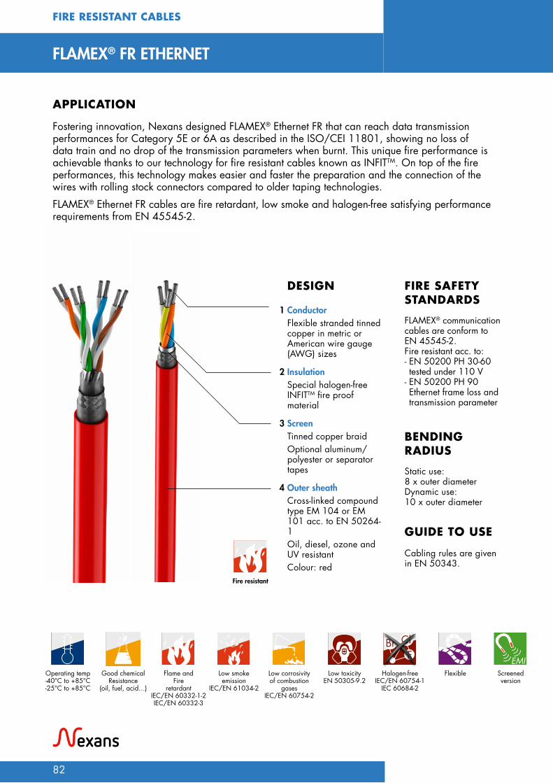
82
FIRE RESISTANT CABLES
FLAMEX® FR ETHERNET
Fostering innovation, Nexans designed FLAMEX® Ethernet FR that can reach data transmission performances for Category 5E or 6A as described in the ISO/CEI 11801, showing no loss of data train and no drop of the transmission parameters when burnt. This unique fire performance is achievable thanks to our technology for fire resistant cables known as INFITTM. On top of the fire performances, this technology makes easier and faster the preparation and the connection of the wires with rolling stock connectors compared to older taping technologies.FLAMEX® Ethernet FR cables are fire retardant, low smoke and halogen-free satisfying performance requirements from EN 45545-2.
APPLICATION
DESIGN
Static use:8 x outer diameterDynamic use:10 x outer diameter
Cabling rules are given in EN 50343.
BENDING RADIUS
GUIDE TO USE
FLAMEX® communication cables are conform to EN 45545-2.Fire resistant acc. to: - EN 50200 PH 30-60 tested under 110 V
- EN 50200 PH 90 Ethernet frame loss and transmission parameter
FIRE SAFETY STANDARDS
1 ConductorFlexible stranded tinned copper in metric or American wire gauge (AWG) sizes
2 InsulationSpecial halogen-free INFITTM fire proof material
3 ScreenTinned copper braid Optional aluminum/polyester or separator tapes
4 Outer sheathCross-linked compound type EM 104 or EM 101 acc. to EN 50264-1 Oil, diesel, ozone and UV resistant Colour: red
EMILow smokeemission
IEC/EN 61034-2
Good chemical Resistance
(oil, fuel, acid…)
Flame and Fire
retardantIEC/EN 60332-1-2 IEC/EN 60332-3
Operating temp-40°C to +85°C-25°C to +85°C
Low corrosivity of combustion
gasesIEC/EN 60754-2
Low toxicityEN 50305-9.2
Halogen-freeIEC/EN 60754-1
IEC 60684-2
Flexible Screened version
Fire resistant

FIRE
RES
ISTA
NT
CABL
ES
83
FIRE RESISTANT ETHERNET 100 Ω NEXANS REFERENCE
CABLE DESIGN
NUMBER OF CORES x CROSS-
SECTION [mm²]
DEDICATED NETWORK
CORE DIAMETER
[mm]
OVERALL DIAMETER APPROX.WEIGHT
[kg/km]
FIRE SAFETY
Min. diameter [mm]
Max. diameter [mm]
2PM653 Pair 4x2x0,25 CAT 6A 2,4 12.0 14.0 170 EN 50200 PH 90 Ethernet protocol
2PM021 Quad 4x0,5 CAT 5E 2,6 8.1 8.5 96 EN 50200 PH 90 Ethernet protocol
2PM694 Quad 4x0,34 - AWG22 CAT 5E 2,2 7.8 8.4 90 EN 50200 PH 90 Ethernet protocol
FIRE RESISTANT WTB-MVB & CAN BUS 120 Ω NEXANS REFERENCE
CABLE DESIGN
NUMBER OF CORES x CROSS-
SECTION [mm²]
DEDICATED NETWORK
CORE DIAMETER
[mm]
OVERALL DIAMETER APPROX.WEIGHT
[kg/km]
FIRE SAFETY
Min. diameter [mm]
Max. diameter [mm]
49556810* Pair 1x2x0,75 WTB 3,4 9.2 10.0 117 EN 50200 PH90
2PM601 Pair 1x2x0,75 WTB 4,5 11.3 11.7 160 EN 50200 PH90
2PM599 Pair 1x2x0,5 MVB 3,7 9.5 10.0 122 EN 50200 PH90
2PM600 quad 4x0,5 MVB 3,4 10.8 11.2 135 EN 50200 PH90
2PM590 pair 1x2x0,5 + 1x0,5 CAN 3,8 +(2,5) 9.8 10.2 125 EN 50200 PH90
* Mica tape underneath the polyethylene-based dielectric
FLA
MEX
® F
R ET
HER
NET

84

HV LOOPS & ACCESSORIESFLAMEX® (N)TMCGCHXOE ........................................................................ 86
READY-TO-INSTALL PRE-ASSEMBLED HV CABLES ............................................ 88
SEPARABLE HV CONNECTORS .................................................................. 90
HV TERMINATIONS .................................................................................. 92
HV
LOO
PS &
A
CCES
SORI
ES
85

86
FLAMEX® (N)TMCGCHXOE 26/45 kVHV SINGLE CORE POWER CABLE
For inside and outside use in railway vehicles. Installation in cable ducts and tubes.Available on request: HV Loop, completely pre-assembled flexible cables with plugs and sealing ends, electrically tested.
APPLICATION
Conductor temperature: -40°C/+90°C/+120°C
DESIGN in line with IEC 60502/EN 50264 Static use:
6 x outer diameterDynamic use: 10 x outer diameter
Cabling rules are given in EN 50343.Permissible current carrying capacities comply with EN 50355.
BENDING RADIUS
GUIDE TO USE
FLAMEX® (N) TMCGCHXOE cables are conform to EN 45545-2. On top of that, the cables are designed to withstand fire tests according to NFPA 130 or GOST-R 31565.
FIRE SAFETY STANDARDS
1 ConductorFlexible stranded tinned copper, acc. to IEC 60228 class 5
2 Inner conductive layerConductive rubber
3 InsulationCross-linked dielectric type EI 110 acc. to EN 50264-1 for high voltage application
4 Inner conductive layerConductive rubber
5 ScreenTinned screen with separator
6 Outer sheathCross-linked compound type EM 104 acc. to EN 50264-1Oil, diesel, ozone and UV resistantColour: black
Operating temp - 40°C to +90°C
Low corrosivity of combustion
gasesIEC/EN 60754-2
Low smokeemission
IEC/EN 61034-2
Halogen-freeIEC/EN 60754-1
IEC 60684-2
Good chemical Resistance
(oil, fuel, acid…)
Flame and Fire
retardantIEC/EN 60332-1-2IEC/EN 60332-3
Good resistance
to UV, humidity
and ozone
Low toxicityEN 50305-9.2
FlexibleClass 5
HV LOOPS & ACCESSORIES

HV
LOO
PS &
A
CCES
SORI
ES
87
FLA
MEX
® (N
)TM
CGCH
XOE
FLAMEX (N)TMCGCHXHXOE section / screen section 26/45kV week/year batch number
Marking
FLAMEX® (N)TMCGCHXOE - 26/45 kV
NEXANSREFERENCE
CROSS-SECTION[mm²]
SCREEN SECTION[mm²]
DIAMETER OVER THE INSULATION
[mm]
MIN. OUTERDIAMETER
[mm]
MAX. OUTERDIAMETER
[mm]
APPROX. WEIGHT[kg/km]
7947 0574 50 16 29.0 34.0 36.0 2100
7947 0575 95 16 32.0 40.0 42.0 2500
7947 0582 120 16 34.0 40.5 42.5 2900
7947 0576 150 16 36.0 41.0 43.0 3200
7947 7903 185 25 37.0 42.0 44.0 3600
7947 0577 240 25 40.0 45.0 48.0 4300
Other constructions on request
ELECTRICAL PROPERTIES
Nominal voltage U0/U (Umax) = 26/45 (54) kV
Max. rated voltage in d.c. installations, one-sided earthed U0 max = 32 kV DC
Test voltage Core/Screen (5 minutes) U = 70 kV
Core/Screen (5 minutes) U = 75 kV
Partial discharge measurement by 52 kV, on pre-assembled flexible cable ≤ 5 pC
FLAMEX® PANTO according to SNCF 10-5299319 and DTREN 150018 on request

88
HV LOOPS & ACCESSORIES
READY-TO-INSTALL PRE-ASSEMBLED HV CABLESCABLES, CONNECTORS AND TERMINATIONS
Pre-assembled FLAMEX® (N)TMCGCHXOE or FLAMEX® PANTO cables are equipped with connectors and terminations. They can be used for traction power supply systems. We manufacture the pre-assembled cables specifically customized in terms of cable length and type of accessories. The cables and flexible cables, primarily checked by us, are assembled with different conductor cross-sections and accessories, depending on customer’s application.
APPLICATION
• Type-tested: All accessories meet the CENELEC HD 629.1 requirements.
• Routine-tested: Depending on customer needs, each pre-assembled cable loop can be tested for AC withstands and partial discharge prior leaving the factory.
The pre-assemblies conform to the requirements from EN 45545-2.
TECHNICAL CHARACTERISTICS FIRE SAFETY STANDARDS
Accessory ASee table for accessory selection
Accessory BSee table for accessory selection
Seperable connectorP484TB/G
Outdoor termination AFN30
Dimensioning basis forwire- / cable length

HV
LOO
PS &
A
CCES
SORI
ES
89
REA
DY-
TO-IN
STA
LL P
RE-A
SSEM
BLED
CA
BLES
FIRE SAFETY STANDARDS
READY-TO-INSTALL PRE-ASSEMBLED CABLESCONNECTORS AND TERMINATIONS
EXAMPLE REQUEST:
Please fill in the applicable information.CHARACTERISTICS 15 kV
Traction power supply system25 kV
Traction power supply system
Cable type
Cable length
Accessory A
Length of shield wire
Accessory B
Length of shield wire
Partial discharge sample test yes / no yes / no
AC withstand test yes / no yes / noIf you do not indicate the length of the shield wire, we will assume a length of 500 mm for accessory «A» and «B».
EXAMPLE FOR ACCESSORIES SELECTION:
System requirements:• Traction power supply system according to EN 50163: 25 kV • Requirement of the creepage distance according to IEC 50124: PD4 • Bushing interface of traction transformer: Interface C
The applicable types of accessories for FLAMEX® (N)TMCGCHXOE 26/45 kV cable can be:CROSS-SECTION OF CONDUCTOR/ SCREEN
DIAMETER OVER CORE INSULATION*
[mm]
ACCESSORY A: SEPARABLE CONNECTOR
ACCESSORY B: TERMINATION
50RF/16 29 P480TB/G-25 AFN30-3
95RF/16 32 P480TB/G-25 AFN30-3
120RF/16 34 P480TB/G-30 AFN36-4
150RF/16 36 P480TB/G-30 AFN36-4
185RF/25 37 P480TB/G-30 AFN36-4
240RF/25 40 P480TB/G-30 AFN36-4
400RF/25 46.5 P484TB/G-37 AFN36-5
The proper accessories type is up to the dia. over core insulation. To choose the right accessories, please double-check the
diameter over core insulation in the respective cable date sheet. If they are not equal, the cable date sheet shall prevail.
Detailed information can be found in the respective accessories data sheet. When dimensioning the preassembled cable length, we take the center points of both cable accessories as the basis. When indicating the length of the shield wire, please also specify whether the shield wire should be lead out on one or both sides.

90
SEPARABLE HV CONNECTORSINTERFACE C, E AND F
Separable connectors are suitable for installation on insulated flexible cable (for example FLAMEX® (N)TMCGCHXOE, FLAMEX® PANTO…). They can be used to connect the cable to other full screened equipment (e.g. traction transformer) in traction power supply systems.
APPLICATION
Separable connectors meet the CENELEC HD 629.1 requirements. • The thick conductive EPDM jacket provides
a total safe to touch screen to ensure safety. • Thanks to new materials the separable
connectors are non-size sensitive. • Each separable connector is tested for
AC withstand and partial discharge prior leaving the factory.
TECHNICAL CHARACTERISTICS
L2
4 9
1
2
3
10
7
L1
56
8
DESIGN
1 Conductive EPDM insert
2 Conductive EPDM jacket
3 Insulating EPDM layer moulded between the insert and the jacket
4 Type C, E or F - interface as described by EN 50180 and EN 50181
5 Bolted or crimp conductor contact
6 Basic insulating plug
7 Cable reducer
8 Conductive rubber cap
9 Clamping screw
10 Earth lead The screen break design enables cable outer sheath testing without removing or dismantling the connector (except 750LR)
HV LOOPS & ACCESSORIES
The separable HV connectors conform to EN 45545-2.
FIRE SAFETY STANDARDS

HV
LOO
PS &
A
CCES
SORI
ES
91
SEPA
RABL
E H
V CO
NN
ECTO
RSSEPARABLE HV CONNECTORS
SEPARABLE CONNECTOR TYPE
L1[mm]
L2[mm]
INTERFACE TYPE DIAMETER OVER CORE INSULATION*
Minimum [mm] Maximum [mm]
(M)430TB/G 290 185 C 13.0 37.6
(M)(P)480TB/G 290 185 C 13.0 37.6
(M)(P)484TB/G 360 185 C 17.0 50.0
(M)(P)400TB/G 350 255 C 13.0 37.6
(M)(P)440TB/G 355 255 C 17.0 50.0
(M)(P)784TB/G 360 205 E 16.0 56.0
Q909TB/G 445 250 F 27.0 68.0
*Information can be found in the respective cable data sheet.

92
HV LOOPS & ACCESSORIES
HV TERMINATIONSAIN & AFN FOR INDOOR AND OUTDOOR
The AIN/AFN termination is suitable for indoor/outdoor installation on insulated flexible cable (for example FLAMEX® (N)TMCGCHXOE, FLAMEX® PANTO…).They can be used to connect the cable to other equipment and bus bars in traction power supply systems.
APPLICATION
Indoor and outdoor terminations meet the CENELEC HD 629.1 requirements.
SPECIFICATIONS AND STANDARDS
DESIGN
1 ConductorLongitudinally sealed mechanical or compression cable lug (alternative pin-type)
2 Inner conductive layerSilicone tube or cap as additional sealing at the transition of the cable lug to the termination housing
3 InsulationHigh flexibility silicone rubber housing
4 Inner conductive layerIntegrated conductive rubber insert
5 ScreenWater sealing mastic
6 Outer sheathEarthing clamp
7 Outer sheathEarth cable lug
1
2
3
4
5
7
6
Ø D
L
4
7
3
2
1
L
Ø D
The HV terminations conform to EN 45545-2.
FIRE SAFETY STANDARDS

HV
LOO
PS &
A
CCES
SORI
ES
93
HV
TERM
INAT
ION
SHV TERMINATIONS
TERMINATION TYPE
CREEPAGEDISTANCE
[mm]
L[mm]
Ø D[mm]
DIAMETER OVER CORE INSULATION*
Minimum [mm] Maximum [mm]
AIN 30-1 414 300 74 23.8 28.4
AIN 30-2 412 300 74 27.1 37.6
AIN 30-3 393 300 81 31.5 42,8
AIN 36-4 506 405 98 31.5 41.0
AIN 36-5 502 405 98 39.0 50.0
AIN 36-6 499 405 98 46.0 58.0
AFN 30-1 695 300 115 23.8 28.4
AFN 30-2 694 300 115 27.1 37.6
AFN 30-3 718 300 127 31.5 42.8
AFN 36-3 755 405 127 28.0 32.0
AFN 36-4 755 405 127 31.5 41.0
AFN 36-5 755 405 127 39.0 50.0
AFN 36-6 755 405 127 46.0 58.0
AFNP 52-3-C 1079 535 127 28.0 32.0
AFNP 52-4-C 1079 535 127 31.5 41.0
AFNP 52-5-C 1079 535 127 39.0 50.0
AFNP 52-6-C 1079 535 127 46.0 58.0
*Information can be found in the respective cable data sheet.

94

SPECIALTIESFLAMEX® HYBRIDS & JUMPERS .................................................................... 96
SPEC
IALT
IES
95

96
FLAMEX® HYBRIDS & JUMPERS
APPLICATIONSNexans produces a complete range of standard or customized jumper cables for power and data transmission outside : trains, subways and tramways.Nexans manufactures 2 jumper cable types:• to supply power in each coach,• to transmit information between coaches and
between chassis and bogie inside a coach.
ADVANTAGESDesigned to conform to the railway standards, these halogen-free cables are intended for applications where an extra-flexibility combined with flame and fire retardancy is required. Nexans jumper cables show an excellent mechanical resistance to abrasion, tensile strength and cut through, but also a very good resistance to chemical agents.
MAIN CHARACTERISTICS• Jumper cables are available
in every type of construction according to customer specifications: - with single and multicore (unscreened and unsheathed and/or screened and sheathed) ;
- with coaxial or data bus cables ;
- with optical elements.• Very high flexibility level
(class 6 stranded conductor)• High reliability: flex life
guarantee > 1million cycles• Excellent mechanical and
chemical resistance• Rated voltage: from
250 V to 3000 V
FLEX LIFE GUARANTEEIn order to guarantee more than 1 million flex cycles, we have developed our own test equipment. Each jumper cable is tested to simulate all specific movements endured during operation.The complex movements are controlled on two horizontal and perpendicular axes and can be customized according to specific client needs.
STANDARDS AND SPECIFICATIONS Jumper cables conform to the international standard EN 45545-2 and to customer specifications that are strongly linked the working conditions of the trains.
SPECIALTIES

SPEC
IALT
IES
97
CONTROL AND DATA
2PI655:11 x (2 x 1.5mm² shielded + 5 x (4 x 1.5 mm²) unshielded
CONTROL AND DATA
2PL270: (2 x 1.5mm²) + (3 x 1.5 mm²) + (4 x 1.5 mm²) + (35 x 1.5 mm²)
ETHERNET
2PJ528: 4 x 0,75 mm² 100 ΩDATA BUS AND CONTROL
2PJ809: 4 x (4 x 0.75 mm² 100 Ω) + 6 x 1.5 mm² Ethernet 100 Ω, MVB 120 Ω
CONTROL AND POWER
2PK464: 30 x 2.5 mm² + 1 x 4 mm² + 1 x 16 mm²
DATA BUS AND CONTROL
2PJ151: 4 x (2 x 0.5 mm² MVB 120 Ω) + 6 x 1.5 mm² + 2 x 0.5 mm² control
Typical constructions designed for more than 1 million cycles
EMILow smokeemission
IEC/EN 61034-2
Good chemical
Resistance(oil, fuel, acid…)
Flame and
Fire retardantIEC/EN 60332-1-2IEC/EN 60332-3EN 50305-9.1
Operating temp - 40°C to +105°C
Low corrosivity of combustion
gasesIEC/EN 60754-2
Low toxicityEN 50305-9.2
Halogen-freeIEC/EN 60754-1
IEC 60684-2
FlexibleClass 5/6

98

CURRENT RATING
99 CURR
ENT
RATI
NG

100
CURRENT RATING
CURRENT RATING OF COPPER WIRES IN FREE AIR FOR SINGLE CORE CABLES
CURRENT RATING [A]
TEMPERATURE CLASS 90°C (45°C) 105°C 120°C 150°C
Standards EN 50264EN 50306
EN 50306 EN 50382 EN 50382
Nominal cross-section [mm²]
0.5 14 - - -
0.75 16 - - -
1 20 23 25 29
1.5 25 29 32 37
2.5 33 38 42 48
4 46 52 58 67
6 60 68 76 88
10 85 97 107 124
16 110 125 139 161
25 150 171 189 219
35 190 217 239 277
50 240 274 302 350
70 300 342 378 438
95 360 410 454 526
120 425 485 536 621
150 490 559 617 715
185 560 638 706 818
240 675 770 851 986
300 775 884 977 1132
400 950 1083 1197 1387
K 1.0 1.14 1.26 1.46
Ambient temperature: 45°C
DERATING COEFFICIENT FOR MULTICORE CABLES IN FREE AIRDERATING COEFFICIENT
NUMBER OF CORES 2 to 4
Derating coefficient (K2) 0.8
CURRENT RATING OF WIRES IN ACCORDANCE WITH EN 50343

101
DERATING COEFFICIENT FOR DIFFERENT WORKING TEMPERATURES ACCORDING TO EN 50343
DERATING COEFFICIENT (K1)
TEMPERATURE CLASS 90°C 105°C 120°C 150°C
35°C 1,11 1,08 1,06 1,05
45°C 1 1 1 1
55°C 0.88 0.91 0.93 0.95
65°C 0.75 0.82 0.86 0.90
75°C 0.58 0.71 0.77 0.85
85°C 0.33 0.58 0.68 0.79
95°C - 0.41 0.58 0.72
105°C - - 0.45 0.65
115°C - - 0.26 0.58
125°C - - - 0.49
135°C - - - 0.38
145°C - - - 0.22
DERATING COEFFICIENT K2 (EN 50343) FOR CABLES IN ACCORDANCE WITH INSTALLATION RULES
NUMBER OF CABLES LOADED
"CABLES ON TRAYS, IN ONE
LAYER TYPE B)"
CABLES ON TRAYS, IN
TWO LAYERS
"CABLES ON TRAYS, IN SEVERAL
LAYERS TYPE C)"
"CABLES ON THE FLOOR OR ON A
WALL TYPE D)"
"CABLES ON A CEILING OR UNDER
FLOOR TYPE E)"
"CABLES IN A CLOSED
TUBE, CONDUIT OR TRAY TYPE F)"
"CABLES IN A CLOSED TUBE OR CONDUIT, THERMALLY INSULATED TYPE G)"
single cable 1.0 1.0 1.0 1.0 0.95 0.95 0.76
2 cables 0.87 0.87 0.87 0.85 0.81 0.80 0.61
3 cables 0.83 0.83 0.78 0.79 0.72 0.70 0.53
4 cables 0.78 0.71 0.71 0.75 0.68 0.65 0.49
8 cables 0.74 0.59 0.52 0.75 0.62 0.52 0.40
12 cables 0.73 0.54 0.45 0.75 0.61 0.45 0.34
16 cables 0.72 0.51 0.41 0.75 0.61 0.41 0.31
20 cables and more
0.71 0.47 0.38 0.75 0.61 0.38 0.29
Calculation I cable: > I load / k1 x k2 x k3 x k4 see EN guide to use
CURR
ENT
RATI
NG

OPERATING TEMPERATURE
WEATHER CONDITIONS
FLEXIBILITY
CHEMICAL ATTACKS
FIRE PERFORMANCES
SMOKE DENSITY
Symbols
This catalogue shows a general description of products which characteristics are not contractual in any case. Nexans reserves the right to change specifications without prior notice.
All total or partial reproduction, done without Nexans authorization is unlawful.
102

LOW TOXICITY
HALOGEN-FREE
GASES CORROSIVITY
ELECTRO MAGNETIC INTERFERENCE
RoHS COMPLIANT
REACH COMPLIANT
EMI
103

Notes
104
...................................................................................................................................................................................................
...................................................................................................................................................................................................
...................................................................................................................................................................................................
...................................................................................................................................................................................................
...................................................................................................................................................................................................
...................................................................................................................................................................................................
...................................................................................................................................................................................................
...................................................................................................................................................................................................
...................................................................................................................................................................................................
...................................................................................................................................................................................................
...................................................................................................................................................................................................
...................................................................................................................................................................................................
...................................................................................................................................................................................................
...................................................................................................................................................................................................
...................................................................................................................................................................................................
...................................................................................................................................................................................................
...................................................................................................................................................................................................
...................................................................................................................................................................................................
...................................................................................................................................................................................................
...................................................................................................................................................................................................
...................................................................................................................................................................................................
...................................................................................................................................................................................................
...................................................................................................................................................................................................
...................................................................................................................................................................................................
...................................................................................................................................................................................................
...................................................................................................................................................................................................
...................................................................................................................................................................................................
...................................................................................................................................................................................................
...................................................................................................................................................................................................
...................................................................................................................................................................................................
...................................................................................................................................................................................................
...................................................................................................................................................................................................

105
...................................................................................................................................................................................................
...................................................................................................................................................................................................
...................................................................................................................................................................................................
...................................................................................................................................................................................................
...................................................................................................................................................................................................
...................................................................................................................................................................................................
...................................................................................................................................................................................................
...................................................................................................................................................................................................
...................................................................................................................................................................................................
...................................................................................................................................................................................................
...................................................................................................................................................................................................
...................................................................................................................................................................................................
...................................................................................................................................................................................................
...................................................................................................................................................................................................
...................................................................................................................................................................................................
...................................................................................................................................................................................................
...................................................................................................................................................................................................
...................................................................................................................................................................................................
...................................................................................................................................................................................................
...................................................................................................................................................................................................
...................................................................................................................................................................................................
...................................................................................................................................................................................................
...................................................................................................................................................................................................
...................................................................................................................................................................................................
...................................................................................................................................................................................................
...................................................................................................................................................................................................
...................................................................................................................................................................................................
...................................................................................................................................................................................................
...................................................................................................................................................................................................
...................................................................................................................................................................................................
...................................................................................................................................................................................................
...................................................................................................................................................................................................

FLAM
EX®
CAB
LES
TO D
ESIG
N M
OBIL
ITY
SOLU
TION
S
Distributed by
Prin
ted
on p
aper
PEF
C 1
00%
Cer
t. N
o PE
FC/1
0-31
-159
2 fro
m s
usta
inab
ly-m
anag
ed fo
rest.
June
202
0 - C
opyr
ight
® 2
020
- Nex
ans
Fran
ce.
Phot
os c
redi
ts: N
exan
s –
Adob
e St
ock/
Ole
ksiy
Mar
k –
Car
los
Ram
írez
de A
rella
no d
el R
ey –
Imm
agin
ario
75 –
LIPS
KIY
PAVE
L –
Ugo
Told
i
For more information, please consult: www.nexans.com/flamex
NexansImmeuble Le Vinci - 4 allée de l’Arche92070 Paris La Défense Cedex - FranceTel.: +33 (0) 1 78 15 00 00
EDIT
ION
2020