Flameproof Zirconia Oxygen Analyzer ZS8C, ZS8D · Flameproof Zirconia Oxygen Analyzer ZS8C, ZS8D...
5
Flameproof Zirconia Oxygen Analyzer ZS8C, ZS8D Bulletin 11M07A03-02E www.yokogawa.com ZS8C, ZS8D Flameproof Zirconia Oxygen Analyzer
Transcript of Flameproof Zirconia Oxygen Analyzer ZS8C, ZS8D · Flameproof Zirconia Oxygen Analyzer ZS8C, ZS8D...

Flameproof Zirconia Oxygen AnalyzerZS8C, ZS8D
Bulletin 11M07A03-02E
www.yokogawa.com
ZS8C, ZS8DFlameproof Zirconia Oxygen Analyzer
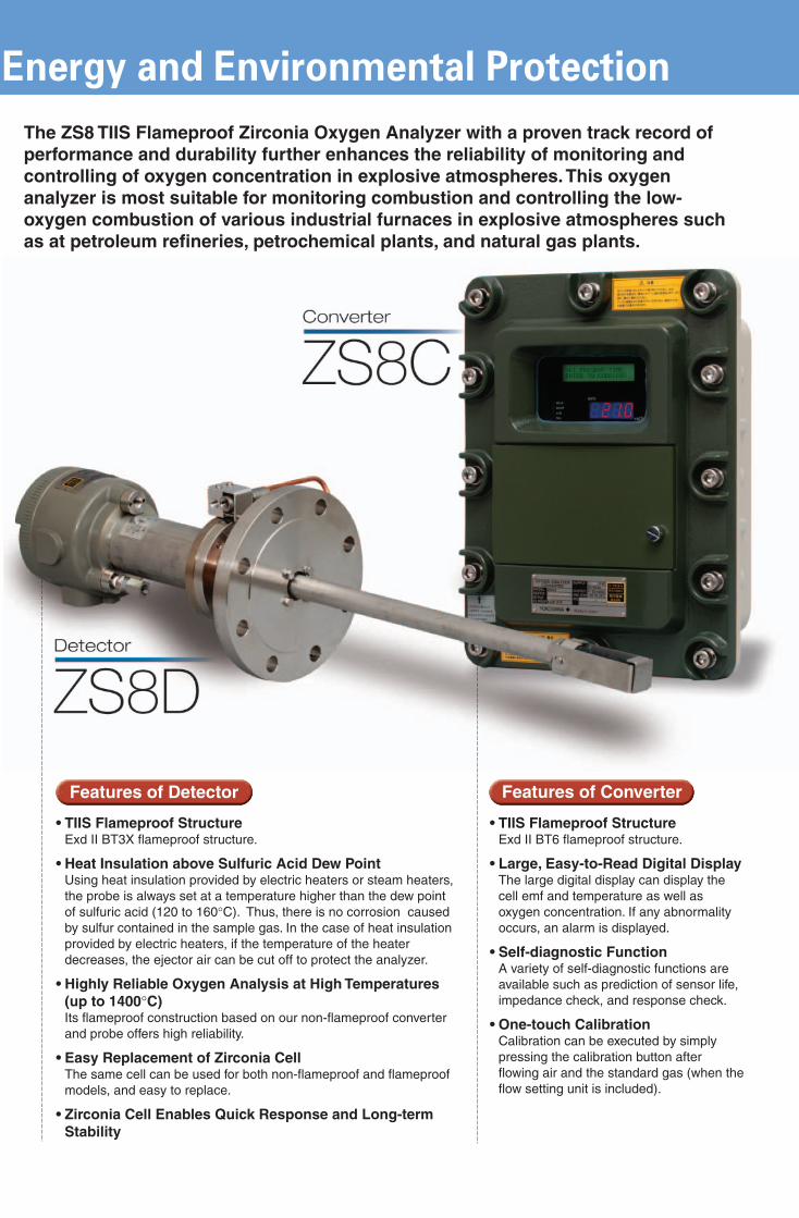
• TIIS Flameproof StructureExd II BT3X flameproof structure.
• Heat Insulation above Sulfuric Acid Dew PointUsing heat insulation provided by electric heaters or steam heaters, the probe is always set at a temperature higher than the dew point of sulfuric acid (120 to 160°C). Thus, there is no corrosion caused by sulfur contained in the sample gas. In the case of heat insulation provided by electric heaters, if the temperature of the heater decreases, the ejector air can be cut off to protect the analyzer.
• Highly Reliable Oxygen Analysis at High Temperatures (up to 1400°C)Its flameproof construction based on our non-flameproof converter and probe offers high reliability.
• Easy Replacement of Zirconia CellThe same cell can be used for both non-flameproof and flameproof models, and easy to replace.
• Zirconia Cell Enables Quick Response and Long-term Stability
• TIIS Flameproof StructureExd II BT6 flameproof structure.
• Large, Easy-to-Read Digital DisplayThe large digital display can display the cell emf and temperature as well as oxygen concentration. If any abnormality occurs, an alarm is displayed.
• Self-diagnostic FunctionA variety of self-diagnostic functions are available such as prediction of sensor life, impedance check, and response check.
• One-touch CalibrationCalibration can be executed by simply pressing the calibration button after flowing air and the standard gas (when the flow setting unit is included).
The ZS8 TIIS Flameproof Zirconia Oxygen Analyzer with a proven track record of performance and durability further enhances the reliability of monitoring and controlling of oxygen concentration in explosive atmospheres. This oxygen analyzer is most suitable for monitoring combustion and controlling the low-oxygen combustion of various industrial furnaces in explosive atmospheres such as at petroleum refineries, petrochemical plants, and natural gas plants.
Features of Detector Features of Converter
Energy and Environmental ProtectionModel and Suffix CodesFlameproof Probe (0 to 1400°C)
Model Suffix code Option DescriptioncodeZS8D -L ------------- -------- General-purpose probe (0 to 800˚C)
-H ------------- -------- High-temperature probe (800 to 1400˚C)Flameproof -J ------------- -------- Exd II BT3X (Maximum surfacestandard temperature: 200˚C)Probe material -A ------------ -------- SUS310S: Specify for general-purpose
probe.-L ------------ -------- SUS304: Specify for high-temperature
probe.Insertion length -010 ------- -------- 0.1 m: Specify for high-temperature probe.
-050 ------- -------- 0.5 m: SUS310S (0 to 800˚C)-070 ------- -------- 0.7 m: SUS310S (0 to 800˚C)-100 ------- -------- 1.0 m: SUS310S (0 to 800˚C)-150 ------- -------- 1.5 m: SUS310S (0 to 800˚C)
Heat insulation model -1 -------- -------- Steam heater (*1)-2 -------- -------- Electric heater
Power supply -N ------ -------- For heat insulation provided by steam(electric heater providing heaters heat insulation) -3 ------ -------- 220V AC, 50/60Hz
-4 ------ -------- 240V AC, 50/60Hz-5 ------ -------- 100V AC, 50/60Hz-8 ------ -------- 115V AC, 50/60Hz
Exhaust method (*2) -N ---- -------- Specify for high-temperature probe.-0 ---- -------- Discharge outside furnace-1 ---- -------- Recirculate in furnace
Flange joint connection -H -- -------- JIS 5K 65 FF, specify for high-tempera-ture probe.
-J -- -------- JIS 10K 100 FF-K -- -------- JPI Class 150 4 RF-A -- -------- ANSI Class 150 4 RF-E -- -------- DIN PN10 DN100 A
Calibration gas, reference gas, J -- -------- Rc1/4and ejector inlet joints (*3) A-- -------- 1/4NPTOption: Heat insulation jacket (*4) /JS --- For steam heaters
/JE --- For electric heaters
(*1) A steam heater [-1] must be specified when heavy oil fuel gas and heavy oil fuel mixture isused or dew point temperature of exhaust gas is about 130˚C. By selecting either -1 or-2, the steam heater or electric heater is installed. For high-temperature probes, only"discharge outside furnace" is applied.
(*2) Select whether to discharge mixed gases (the sample gas sucked in by the ejector plusthe ejector air) outside the furnace or to recirculate them in the furnace. If -1 is selected, agas-return pipe is provided.
(*3) The flameproof probe is equipped with a check valve and auxiliary ejector assembly asstandard.
(*4) Heat insulation jacket must be ordered. It is essential to use owning hood in where in-stalled in surrounding rain.
Probe with Flameproof Terminal Box (0 to 600˚C)
Model Suffix code Option DescriptioncodeZO21DW -L -------------- -------- Probe with flameproof terminal boxInsertion length -040 ----------- -------- 0.4m
-100 ----------- -------- 1.0m-150 ----------- -------- 1.5m-200 ----------- -------- 2.0m-300 ----------- -------- 3.0m
Flange joint -J ---------- -------- JIS 10K 100A FF SUS304connection -A ---------- -------- ANSI Class 150 4 RF SUS304
-E ---------- -------- DIN PN DN100 A SUS304Style code *A -------- -------- Style AOption: Check valve /CV--- With check valve
Stop valve /SV--- With stop valveCable gland /G---- Cable glands (2 pieces)
(*A) Cable gland [/G] must be specified when installed in hazardous area.
Flameproof Converter
Model Suffix code Option DescriptioncodeZS8C ----------------- -------- ConverterFlameproof -J ------------- -------- Exd II BT6standard (Max. surface temperature 85˚C)Power supply -3 ------------ -------- 220V AC, 50/60Hz
-4 ------------ -------- 240V AC, 50/60Hz-5 ------------ -------- 100V AC, 50/60Hz-8 ------------ -------- 115V AC, 50/60Hz
Auxiliary heater -0 ---------- -------- For probe heat insulation provided bythermostat for steam heatersprobe(*1) -1 ---------- -------- For probe heat insulation provided by
electric heatersPanel -E ------- -------- English
-J ------- -------- JapaneseOption: Wall mounting /W ---- With wall mounting bracket
/P ----- With pipe mounting bracketAir-purge connection /AP2 -- 1/4NPT
/AP1 -- Rc1/4
(*1) A steam heater [-0] must be specified when heavy oil fuel, gas and heavy oil fuel mixtureis used or dew point temperature of exhaust gas is about 130˚C.
Flameproof Zirconia Oxygen Analyzer
ZS8C, ZS8DZS8C, ZS8D
(-) Sample gas contact part
(+) Preference gas contact part
Ceramic
(+) Electrode on reference side
Bolt
Calibration gas pipe
Metal O-ringCellScreen
Bracket
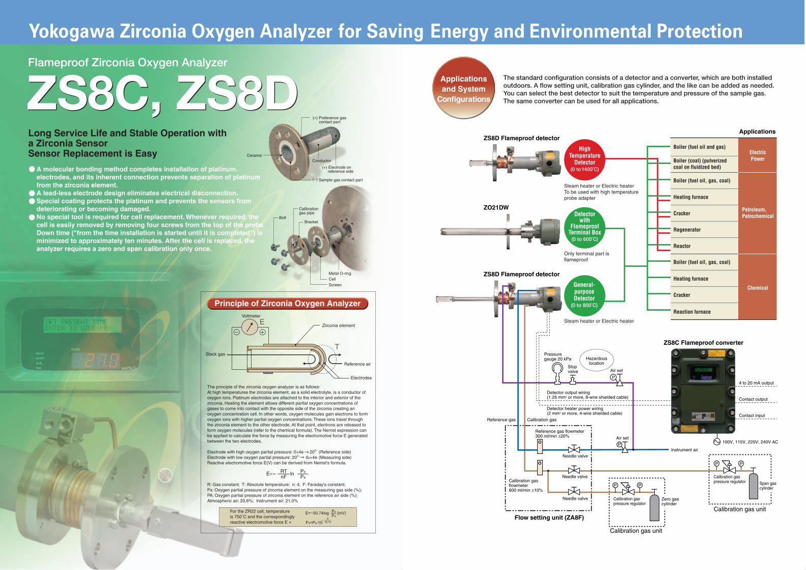
Long Service Life and Stable Operation witha Zirconia SensorSensor Replacement is Easy
Conductor
E
T
Principle of Zirconia Oxygen Analyzer
The principle of the zirconia oxygen analyzer is as follows:At high temperatures the zirconia element, as a solid electrolyte, is a conductor of oxygen ions. Platinum electrodes are attached to the interior and exterior of the zirconia. Heating the element allows different partial oxygen concentrations of gases to come into contact with the opposite side of the zirconia creating anoxygen concentration cell. In other words, oxygen molecules gain electrons to form oxygen ions with higher partial oxygen concentrations. These ions travel through the zirconia element to the other electrode. At that point, electrons are released to form oxygen molecules (refer to the chemical formula). The Nernst expression can be applied to calculate the force by measuring the electromotive force E generated between the two electrodes.
Electrode with high oxygen partial pressure: 0+4e 202- (Reference side)Electrode with low oxygen partial pressure: 202- 02+4e (Measuring side)Reactive electromotive force E(V) can be derived from Nemst's formula.
R: Gas constant; T: Absolute temperature; n: 4; F: Faraday's constant;Px: Oxygen partial pressure of zirconia element on the measuring gas side (%);PA: Oxygen partial pressure of zirconia element on the reference air side (%);Atmospheric air: 20.6%; Instrument air: 21.0%
For the ZR22 cell, temperatureis 750˚C and the correspondinglyreactive electromotive force E =
PX
PAE=-50.74log -[mV]
PX=PA 10--
E50.74
E=--ln -RTnF
PX
PA
Voltmeter
Stack gas
Zirconia element
Reference air
Electrodes
A molecular bonding method completes installation of platinum.electrodes, and its inherent connection prevents separation of platinumfrom the zirconia element.A lead-less electrode design eliminates electrical disconnection.Special coating protects the platinum and prevents the sensors fromdeteriorating or becoming damaged.No special tool is required for cell replacement. Whenever required, thecell is easily removed by removing four screws from the top of the probe.Down time ("from the time installation is started until it is completed") isminimized to approximately ten minutes. After the cell is replaced, theanalyzer requires a zero and span calibration only once.
Pressure gauge 20 kPa
Air set
Hazardouslocation
Detector output wiring (1.25 mm2 or more, 8-wire shielded cable)
Detector heater power wiring (2 mm2 or more, 4-wire shielded cable)
4 to 20 mA output
Contact output
Contact input
Calibration gaspressure regulator
Calibration gaspressure regulatorCalibration gas
flowmeter600 ml/min ±10%
Calibration gas
Reference gas flowmeter300 ml/min ±20%
Reference gas
Needle valve
Needle valve
Needle valve
100V, 115V, 220V, 240V AC
Instrument air
Flow setting unit (ZA8F)
Zero gascylinder
Calibration gas unit
Span gascylinder
Calibration gas unit
Stopvalve
Air set
P
P
P P
P P
ZS8C Flameproof converter
Applications
ElectricPower
Petroleum,Petrochemical
Chemical
The standard configuration consists of a detector and a converter, which are both installed outdoors. A flow setting unit, calibration gas cylinder, and the like can be added as needed. You can select the best detector to suit the temperature and pressure of the sample gas. The same converter can be used for all applications.
Applicationsand System
Configurations
ZS8D Flameproof detector
ZO21DW
ZS8D Flameproof detector
(0 to 1400˚C)
HighTemperature
Detector
Steam heater or Electric heaterTo be used with high temperature probe adapter
(0 to 600˚C)
Detectorwith
FlameproofTerminal Box
Only terminal part is flameproof
Steam heater or Electric heater
General-purposeDetector
(0 to 800˚C)
Boiler (fuel oil and gas)
Boiler (coal) (pulverized coal on fluidized bed)
Boiler (fuel oil, gas, coal)
Boiler (fuel oil, gas, coal)
Heating furnace
Cracker
Regenerator
Reactor
Heating furnace
Cracker
Reaction furnace
Yokogawa Zirconia Oxygen Analyzer for Saving Energy and Environmental Protection
Flameproof Converter ZS8C Unit: mm
(405)Ejector inletEjector
Ejector outlet
Carborundumfilter
Insertion length l
Mountingflange
Ejector
Reference air outlet
Approx. 83
Approx. 93
Reference air inlet With sealing plug
Calibration gas inlet
Check valve
Two G3/4 openings for wiring
(303)
150
Flameproof Detector ZS8D
Section A-A
401
303
186.5
34
210
103.5
55.5
28.5 28.5 28.5 28.5 28.5 28.5
112
79
Four 10-min dia.openings
2-inch (JIS 50 A) mountingpipe (option code: /p)Approx. 54
Six G3/4 openings for wiring (with flame arrester)Seven G3/4 openings for wiring (without flame arrester)
Purge air inlet (optional) (without flame arrester)
Wall-mounting bracket (code: /W)Option code:
/AP1: Rc 1/4/AP2: 1/4 NPT
Standard SpecificationsGeneral Specifications
Measurement object Oxygen concentration in combustion exhaust gasesand mixed gases (excluding flammable gases)
Measurement system Zirconia systemFlameproof construction Detector: Exd II BT3X (Max. surface temperature 200˚C)
Converter: Exd II BT6 (Max. surface temperature 85˚C)Measurement range Display: 0 to 100 vol%O2
Output: 0 to 5 vol%O2 to 0 to 25 vol%O2
Warm-up time Approx. 30 minutesMaximum distance between 300 m or less with 1.25 mm2 conductorsdetector and converterPower supply 100, 115, 220, 240 V AC +10%, -15% 50/60 HzPower consumption Analyzer: 80 VA for ordinary use, Max. 270 VA
Electric heaters providing heat insulation: Approx. 200VA for ordinary use, Max. approx. 400 VA
DetectorFlameproof Detector ZS8DSampling method Air ejector method
Ejector air; Supply pressure 20 kPa, flow rate at4 l/min or less
Sample gas conditions Temperature:ZS8D-L-J-; 0 to 800˚C (general)ZS8D-H; 800 to 1400˚C (high-temperature)
Pressure: -5 to 5 kPa for ZS8D-L general purpose-1.5 to 5 kPa for ZS8D-H high temperature
Flow velocity: 30 m/s or lessDust amount: 500 mg/Nm3 or less
Heat insulation Steam heater when heavy oil fuel or heavy oil andgas fuel mixture is used. Electric heaters when gasfuel is used.
Surface temperature 200˚C or lessReference gas Instrument air 300 ml/min ± 20%Calibration gas Instrument air and standard gas 600 ml/min ±10%Insertion length 0.5, 0.7, 1.0, 1.5 mInstallation Flange mounting
Flange: ZS8D-L: JIS 10K 100 FF SUS304, JPI Class150 4 RF SUS304, ANSI Class 150 4 RFSUS304, DIN PN10 DN100 A SUS304ZS8D-H: JIS 5K 65 FF SUS304
Joint: Rc1/4 or 1/4NPTMaterial in contact Detector SUS310S (or SUS304), Zirconia, SUS304with gas (flange), SUS316 (tube)Construction Flameproof Exd II BT3XCase material Material in contact with gas: SUS316, Terminal box:
Aluminum, Others: SUS304Weight Approx. 10.3 kg to 17 kg
Detector with Flameproof Terminal Box ZO21DWSample gas condition Temperature: 0 to 600˚C
Pressure: -20 to +20 kPaAmbient temperature -10 to +70˚C (terminal box temperature)Reference air flow rate Instrument air 800 ml/min.Material in contact Detector: SUS316, Zirconia, SUS304 (flange)with gasInsertion length 0.4, 1.0, 1.5, 2.0, 3.0 mInstallation Flange mounting (FF)
Flange: JIS 10K 100 A FF SUS304, ANSI Class 1504 RF SUS304, DIN PN10 DN100 A SUS304
Joint: Rc1/8
Construction The terminal box is explosion protected (d2G4).Weight Approx. 6.5 kg to 20.0 kg
Flameproof Converter ZS8CAnalog output signal 4 to 20 mA DC (max. load resistance 550 Ω), input/
output isolationRange: any settings between 0 to 5 vol%O2 to 0 to 25vol%O2; switching between 2 ranges by external con-tact input possible(optional): partial range possible
Contact output 3 points, contact capacity 30 V DC 2A, 250 V AC 2A(resistive load)Programmable for each contact output: (1) Abnor-mal (self-diagnosis) (2) HiHi alarm (3) Hi alarm (4)LoLo alarm (5) Lo alarm (6) Entry (7) Range switch-ing answerback (8) Warm-up (9) Reduction of cali-bration-gas pressure (repeat output of contact input)(10) Calibration (11) Blow-back
Contact output for Solid State Relay (Triac) output: 2 pointssolenoid valve Contact capacity: 250 V AC, 1 ASerial communications RS-422-A interfaceSelf-diagnosis Abnormal cell, abnormal cell temperature (low) (high),
abnormal analog circuit, abnormal calibration, abnor-mal ROM/RAM, power failure
Contact input (optional) 2 points, isolatedProgrammable for each contact input: (1) Reductionof calibration-gas pressure (2) Range switching (3)External calibration start (4) Process abnormal alarm(5) Blow-back start
Calibration One-touch, automatic/semiautomatic (optional)Calibration gas 0.3 to 25 vol%O2 (min. setting unit: 0.01 vol%O2)concentration Use the standard zero and span gases which are gassetting range mixtures of nitrogen and about 10% oxygen for an 80
to 100% scale.Ambient temperature -20 to +55˚CPower supply 100, 115, 220, 240 V AC +10%, -15%, 50/60 HzConstruction Exd II BT6, JIS C0920 waterproof, NEMA3 or equivalentInstallation Wall or pipe mountingCase material Aluminum alloyPaint colors 0.6GY3.1/2.0 (for instrument front cover) and
2.5Y8.4/1.2 (instrument case)Paint Baked epoxy resinWeight Approx. 19 kg (100 to 115 V AC)
Approx. 20.5 kg (220 to 240 V AC)
For details, refer to General Specification, GS11M7A3-E.
CharacteristicsRepeatability ± 0.5% of span (0 to 5 vol%O2 or more and up to 0 to
25 vol%O2 range)Linearity ± 1% of span (0 to 5 vol%O2 or more and up to 0 to
25 vol%O2 range)Drift ± 2.0% of span/month (both zero and span)Response time 90% response within 5 seconds (measured when gas
is fed through the calibration gas inlet and the ana-log output signal begins to change)
External Dimensions
Flameproof Zirconia Oxygen AnalyzerZS8C, ZS8D
Bulletin 11M07A03-02E
www.yokogawa.com
ZS8C, ZS8DFlameproof Zirconia Oxygen Analyzer
• TIIS Flameproof StructureExd II BT3X flameproof structure.
• Heat Insulation above Sulfuric Acid Dew PointUsing heat insulation provided by electric heaters or steam heaters, the probe is always set at a temperature higher than the dew point of sulfuric acid (120 to 160°C). Thus, there is no corrosion caused by sulfur contained in the sample gas. In the case of heat insulation provided by electric heaters, if the temperature of the heater decreases, the ejector air can be cut off to protect the analyzer.
• Highly Reliable Oxygen Analysis at High Temperatures (up to 1400°C)Its flameproof construction based on our non-flameproof converter and probe offers high reliability.
• Easy Replacement of Zirconia CellThe same cell can be used for both non-flameproof and flameproof models, and easy to replace.
• Zirconia Cell Enables Quick Response and Long-term Stability
• TIIS Flameproof StructureExd II BT6 flameproof structure.
• Large, Easy-to-Read Digital DisplayThe large digital display can display the cell emf and temperature as well as oxygen concentration. If any abnormality occurs, an alarm is displayed.
• Self-diagnostic FunctionA variety of self-diagnostic functions are available such as prediction of sensor life, impedance check, and response check.
• One-touch CalibrationCalibration can be executed by simply pressing the calibration button after flowing air and the standard gas (when the flow setting unit is included).
The ZS8 TIIS Flameproof Zirconia Oxygen Analyzer with a proven track record of performance and durability further enhances the reliability of monitoring and controlling of oxygen concentration in explosive atmospheres. This oxygen analyzer is most suitable for monitoring combustion and controlling the low-oxygen combustion of various industrial furnaces in explosive atmospheres such as at petroleum refineries, petrochemical plants, and natural gas plants.
Features of Detector Features of Converter
Energy and Environmental ProtectionModel and Suffix CodesFlameproof Probe (0 to 1400°C)
Model Suffix code Option DescriptioncodeZS8D -L ------------- -------- General-purpose probe (0 to 800˚C)
-H ------------- -------- High-temperature probe (800 to 1400˚C)Flameproof -J ------------- -------- Exd II BT3X (Maximum surfacestandard temperature: 200˚C)Probe material -A ------------ -------- SUS310S: Specify for general-purpose
probe.-L ------------ -------- SUS304: Specify for high-temperature
probe.Insertion length -010 ------- -------- 0.1 m: Specify for high-temperature probe.
-050 ------- -------- 0.5 m: SUS310S (0 to 800˚C)-070 ------- -------- 0.7 m: SUS310S (0 to 800˚C)-100 ------- -------- 1.0 m: SUS310S (0 to 800˚C)-150 ------- -------- 1.5 m: SUS310S (0 to 800˚C)
Heat insulation model -1 -------- -------- Steam heater (*1)-2 -------- -------- Electric heater
Power supply -N ------ -------- For heat insulation provided by steam(electric heater providing heaters heat insulation) -3 ------ -------- 220V AC, 50/60Hz
-4 ------ -------- 240V AC, 50/60Hz-5 ------ -------- 100V AC, 50/60Hz-8 ------ -------- 115V AC, 50/60Hz
Exhaust method (*2) -N ---- -------- Specify for high-temperature probe.-0 ---- -------- Discharge outside furnace-1 ---- -------- Recirculate in furnace
Flange joint connection -H -- -------- JIS 5K 65 FF, specify for high-tempera-ture probe.
-J -- -------- JIS 10K 100 FF-K -- -------- JPI Class 150 4 RF-A -- -------- ANSI Class 150 4 RF-E -- -------- DIN PN10 DN100 A
Calibration gas, reference gas, J -- -------- Rc1/4and ejector inlet joints (*3) A-- -------- 1/4NPTOption: Heat insulation jacket (*4) /JS --- For steam heaters
/JE --- For electric heaters
(*1) A steam heater [-1] must be specified when heavy oil fuel gas and heavy oil fuel mixture isused or dew point temperature of exhaust gas is about 130˚C. By selecting either -1 or-2, the steam heater or electric heater is installed. For high-temperature probes, only"discharge outside furnace" is applied.
(*2) Select whether to discharge mixed gases (the sample gas sucked in by the ejector plusthe ejector air) outside the furnace or to recirculate them in the furnace. If -1 is selected, agas-return pipe is provided.
(*3) The flameproof probe is equipped with a check valve and auxiliary ejector assembly asstandard.
(*4) Heat insulation jacket must be ordered. It is essential to use owning hood in where in-stalled in surrounding rain.
Probe with Flameproof Terminal Box (0 to 600˚C)
Model Suffix code Option DescriptioncodeZO21DW -L -------------- -------- Probe with flameproof terminal boxInsertion length -040 ----------- -------- 0.4m
-100 ----------- -------- 1.0m-150 ----------- -------- 1.5m-200 ----------- -------- 2.0m-300 ----------- -------- 3.0m
Flange joint -J ---------- -------- JIS 10K 100A FF SUS304connection -A ---------- -------- ANSI Class 150 4 RF SUS304
-E ---------- -------- DIN PN DN100 A SUS304Style code *A -------- -------- Style AOption: Check valve /CV--- With check valve
Stop valve /SV--- With stop valveCable gland /G---- Cable glands (2 pieces)
(*A) Cable gland [/G] must be specified when installed in hazardous area.
Flameproof Converter
Model Suffix code Option DescriptioncodeZS8C ----------------- -------- ConverterFlameproof -J ------------- -------- Exd II BT6standard (Max. surface temperature 85˚C)Power supply -3 ------------ -------- 220V AC, 50/60Hz
-4 ------------ -------- 240V AC, 50/60Hz-5 ------------ -------- 100V AC, 50/60Hz-8 ------------ -------- 115V AC, 50/60Hz
Auxiliary heater -0 ---------- -------- For probe heat insulation provided bythermostat for steam heatersprobe(*1) -1 ---------- -------- For probe heat insulation provided by
electric heatersPanel -E ------- -------- English
-J ------- -------- JapaneseOption: Wall mounting /W ---- With wall mounting bracket
/P ----- With pipe mounting bracketAir-purge connection /AP2 -- 1/4NPT
/AP1 -- Rc1/4
(*1) A steam heater [-0] must be specified when heavy oil fuel, gas and heavy oil fuel mixtureis used or dew point temperature of exhaust gas is about 130˚C.
Flameproof Zirconia Oxygen Analyzer
ZS8C, ZS8DZS8C, ZS8D
(-) Sample gas contact part
(+) Preference gas contact part
Ceramic
(+) Electrode on reference side
Bolt
Calibration gas pipe
Metal O-ringCellScreen
Bracket
Long Service Life and Stable Operation witha Zirconia SensorSensor Replacement is Easy
Conductor
E
T
Principle of Zirconia Oxygen Analyzer
The principle of the zirconia oxygen analyzer is as follows:At high temperatures the zirconia element, as a solid electrolyte, is a conductor of oxygen ions. Platinum electrodes are attached to the interior and exterior of the zirconia. Heating the element allows different partial oxygen concentrations of gases to come into contact with the opposite side of the zirconia creating anoxygen concentration cell. In other words, oxygen molecules gain electrons to form oxygen ions with higher partial oxygen concentrations. These ions travel through the zirconia element to the other electrode. At that point, electrons are released to form oxygen molecules (refer to the chemical formula). The Nernst expression can be applied to calculate the force by measuring the electromotive force E generated between the two electrodes.
Electrode with high oxygen partial pressure: 0+4e 202- (Reference side)Electrode with low oxygen partial pressure: 202- 02+4e (Measuring side)Reactive electromotive force E(V) can be derived from Nemst's formula.
R: Gas constant; T: Absolute temperature; n: 4; F: Faraday's constant;Px: Oxygen partial pressure of zirconia element on the measuring gas side (%);PA: Oxygen partial pressure of zirconia element on the reference air side (%);Atmospheric air: 20.6%; Instrument air: 21.0%
For the ZR22 cell, temperatureis 750˚C and the correspondinglyreactive electromotive force E =
PX
PAE=-50.74log -[mV]
PX=PA 10--
E50.74
E=--ln -RTnF
PX
PA
Voltmeter
Stack gas
Zirconia element
Reference air
Electrodes
A molecular bonding method completes installation of platinum.electrodes, and its inherent connection prevents separation of platinumfrom the zirconia element.A lead-less electrode design eliminates electrical disconnection.Special coating protects the platinum and prevents the sensors fromdeteriorating or becoming damaged.No special tool is required for cell replacement. Whenever required, thecell is easily removed by removing four screws from the top of the probe.Down time ("from the time installation is started until it is completed") isminimized to approximately ten minutes. After the cell is replaced, theanalyzer requires a zero and span calibration only once.
Pressure gauge 20 kPa
Air set
Hazardouslocation
Detector output wiring (1.25 mm2 or more, 8-wire shielded cable)
Detector heater power wiring (2 mm2 or more, 4-wire shielded cable)
4 to 20 mA output
Contact output
Contact input
Calibration gaspressure regulator
Calibration gaspressure regulatorCalibration gas
flowmeter600 ml/min ±10%
Calibration gas
Reference gas flowmeter300 ml/min ±20%
Reference gas
Needle valve
Needle valve
Needle valve
100V, 115V, 220V, 240V AC
Instrument air
Flow setting unit (ZA8F)
Zero gascylinder
Calibration gas unit
Span gascylinder
Calibration gas unit
Stopvalve
Air set
P
P
P P
P P
ZS8C Flameproof converter
Applications
ElectricPower
Petroleum,Petrochemical
Chemical
The standard configuration consists of a detector and a converter, which are both installed outdoors. A flow setting unit, calibration gas cylinder, and the like can be added as needed. You can select the best detector to suit the temperature and pressure of the sample gas. The same converter can be used for all applications.
Applicationsand System
Configurations
ZS8D Flameproof detector
ZO21DW
ZS8D Flameproof detector
(0 to 1400˚C)
HighTemperature
Detector
Steam heater or Electric heaterTo be used with high temperature probe adapter
(0 to 600˚C)
Detectorwith
FlameproofTerminal Box
Only terminal part is flameproof
Steam heater or Electric heater
General-purposeDetector
(0 to 800˚C)
Boiler (fuel oil and gas)
Boiler (coal) (pulverized coal on fluidized bed)
Boiler (fuel oil, gas, coal)
Boiler (fuel oil, gas, coal)
Heating furnace
Cracker
Regenerator
Reactor
Heating furnace
Cracker
Reaction furnace
Yokogawa Zirconia Oxygen Analyzer for Saving Energy and Environmental Protection
Flameproof Converter ZS8C Unit: mm
(405)Ejector inletEjector
Ejector outlet
Carborundumfilter
Insertion length l
Mountingflange
Ejector
Reference air outlet
Approx. 83
Approx. 93
Reference air inlet With sealing plug
Calibration gas inlet
Check valve
Two G3/4 openings for wiring
(303)
150
Flameproof Detector ZS8D
Section A-A
401
303
186.5
34
210
103.5
55.5
28.5 28.5 28.5 28.5 28.5 28.5
112
79
Four 10-min dia.openings
2-inch (JIS 50 A) mountingpipe (option code: /p)Approx. 54
Six G3/4 openings for wiring (with flame arrester)Seven G3/4 openings for wiring (without flame arrester)
Purge air inlet (optional) (without flame arrester)
Wall-mounting bracket (code: /W)Option code:
/AP1: Rc 1/4/AP2: 1/4 NPT
Standard SpecificationsGeneral Specifications
Measurement object Oxygen concentration in combustion exhaust gasesand mixed gases (excluding flammable gases)
Measurement system Zirconia systemFlameproof construction Detector: Exd II BT3X (Max. surface temperature 200˚C)
Converter: Exd II BT6 (Max. surface temperature 85˚C)Measurement range Display: 0 to 100 vol%O2
Output: 0 to 5 vol%O2 to 0 to 25 vol%O2
Warm-up time Approx. 30 minutesMaximum distance between 300 m or less with 1.25 mm2 conductorsdetector and converterPower supply 100, 115, 220, 240 V AC +10%, -15% 50/60 HzPower consumption Analyzer: 80 VA for ordinary use, Max. 270 VA
Electric heaters providing heat insulation: Approx. 200VA for ordinary use, Max. approx. 400 VA
DetectorFlameproof Detector ZS8DSampling method Air ejector method
Ejector air; Supply pressure 20 kPa, flow rate at4 l/min or less
Sample gas conditions Temperature:ZS8D-L-J-; 0 to 800˚C (general)ZS8D-H; 800 to 1400˚C (high-temperature)
Pressure: -5 to 5 kPa for ZS8D-L general purpose-1.5 to 5 kPa for ZS8D-H high temperature
Flow velocity: 30 m/s or lessDust amount: 500 mg/Nm3 or less
Heat insulation Steam heater when heavy oil fuel or heavy oil andgas fuel mixture is used. Electric heaters when gasfuel is used.
Surface temperature 200˚C or lessReference gas Instrument air 300 ml/min ± 20%Calibration gas Instrument air and standard gas 600 ml/min ±10%Insertion length 0.5, 0.7, 1.0, 1.5 mInstallation Flange mounting
Flange: ZS8D-L: JIS 10K 100 FF SUS304, JPI Class150 4 RF SUS304, ANSI Class 150 4 RFSUS304, DIN PN10 DN100 A SUS304ZS8D-H: JIS 5K 65 FF SUS304
Joint: Rc1/4 or 1/4NPTMaterial in contact Detector SUS310S (or SUS304), Zirconia, SUS304with gas (flange), SUS316 (tube)Construction Flameproof Exd II BT3XCase material Material in contact with gas: SUS316, Terminal box:
Aluminum, Others: SUS304Weight Approx. 10.3 kg to 17 kg
Detector with Flameproof Terminal Box ZO21DWSample gas condition Temperature: 0 to 600˚C
Pressure: -20 to +20 kPaAmbient temperature -10 to +70˚C (terminal box temperature)Reference air flow rate Instrument air 800 ml/min.Material in contact Detector: SUS316, Zirconia, SUS304 (flange)with gasInsertion length 0.4, 1.0, 1.5, 2.0, 3.0 mInstallation Flange mounting (FF)
Flange: JIS 10K 100 A FF SUS304, ANSI Class 1504 RF SUS304, DIN PN10 DN100 A SUS304
Joint: Rc1/8
Construction The terminal box is explosion protected (d2G4).Weight Approx. 6.5 kg to 20.0 kg
Flameproof Converter ZS8CAnalog output signal 4 to 20 mA DC (max. load resistance 550 Ω), input/
output isolationRange: any settings between 0 to 5 vol%O2 to 0 to 25vol%O2; switching between 2 ranges by external con-tact input possible(optional): partial range possible
Contact output 3 points, contact capacity 30 V DC 2A, 250 V AC 2A(resistive load)Programmable for each contact output: (1) Abnor-mal (self-diagnosis) (2) HiHi alarm (3) Hi alarm (4)LoLo alarm (5) Lo alarm (6) Entry (7) Range switch-ing answerback (8) Warm-up (9) Reduction of cali-bration-gas pressure (repeat output of contact input)(10) Calibration (11) Blow-back
Contact output for Solid State Relay (Triac) output: 2 pointssolenoid valve Contact capacity: 250 V AC, 1 ASerial communications RS-422-A interfaceSelf-diagnosis Abnormal cell, abnormal cell temperature (low) (high),
abnormal analog circuit, abnormal calibration, abnor-mal ROM/RAM, power failure
Contact input (optional) 2 points, isolatedProgrammable for each contact input: (1) Reductionof calibration-gas pressure (2) Range switching (3)External calibration start (4) Process abnormal alarm(5) Blow-back start
Calibration One-touch, automatic/semiautomatic (optional)Calibration gas 0.3 to 25 vol%O2 (min. setting unit: 0.01 vol%O2)concentration Use the standard zero and span gases which are gassetting range mixtures of nitrogen and about 10% oxygen for an 80
to 100% scale.Ambient temperature -20 to +55˚CPower supply 100, 115, 220, 240 V AC +10%, -15%, 50/60 HzConstruction Exd II BT6, JIS C0920 waterproof, NEMA3 or equivalentInstallation Wall or pipe mountingCase material Aluminum alloyPaint colors 0.6GY3.1/2.0 (for instrument front cover) and
2.5Y8.4/1.2 (instrument case)Paint Baked epoxy resinWeight Approx. 19 kg (100 to 115 V AC)
Approx. 20.5 kg (220 to 240 V AC)
For details, refer to General Specification, GS11M7A3-E.
CharacteristicsRepeatability ± 0.5% of span (0 to 5 vol%O2 or more and up to 0 to
25 vol%O2 range)Linearity ± 1% of span (0 to 5 vol%O2 or more and up to 0 to
25 vol%O2 range)Drift ± 2.0% of span/month (both zero and span)Response time 90% response within 5 seconds (measured when gas
is fed through the calibration gas inlet and the ana-log output signal begins to change)
External Dimensions

Flameproof Zirconia Oxygen AnalyzerZS8C, ZS8D
Bulletin 11M07A03-02E
www.yokogawa.com
ZS8C, ZS8DFlameproof Zirconia Oxygen Analyzer
• TIIS Flameproof StructureExd II BT3X flameproof structure.
• Heat Insulation above Sulfuric Acid Dew PointUsing heat insulation provided by electric heaters or steam heaters, the probe is always set at a temperature higher than the dew point of sulfuric acid (120 to 160°C). Thus, there is no corrosion caused by sulfur contained in the sample gas. In the case of heat insulation provided by electric heaters, if the temperature of the heater decreases, the ejector air can be cut off to protect the analyzer.
• Highly Reliable Oxygen Analysis at High Temperatures (up to 1400°C)Its flameproof construction based on our non-flameproof converter and probe offers high reliability.
• Easy Replacement of Zirconia CellThe same cell can be used for both non-flameproof and flameproof models, and easy to replace.
• Zirconia Cell Enables Quick Response and Long-term Stability
• TIIS Flameproof StructureExd II BT6 flameproof structure.
• Large, Easy-to-Read Digital DisplayThe large digital display can display the cell emf and temperature as well as oxygen concentration. If any abnormality occurs, an alarm is displayed.
• Self-diagnostic FunctionA variety of self-diagnostic functions are available such as prediction of sensor life, impedance check, and response check.
• One-touch CalibrationCalibration can be executed by simply pressing the calibration button after flowing air and the standard gas (when the flow setting unit is included).
The ZS8 TIIS Flameproof Zirconia Oxygen Analyzer with a proven track record of performance and durability further enhances the reliability of monitoring and controlling of oxygen concentration in explosive atmospheres. This oxygen analyzer is most suitable for monitoring combustion and controlling the low-oxygen combustion of various industrial furnaces in explosive atmospheres such as at petroleum refineries, petrochemical plants, and natural gas plants.
Features of Detector Features of Converter
Energy and Environmental ProtectionModel and Suffix CodesFlameproof Probe (0 to 1400°C)
Model Suffix code Option DescriptioncodeZS8D -L ------------- -------- General-purpose probe (0 to 800˚C)
-H ------------- -------- High-temperature probe (800 to 1400˚C)Flameproof -J ------------- -------- Exd II BT3X (Maximum surfacestandard temperature: 200˚C)Probe material -A ------------ -------- SUS310S: Specify for general-purpose
probe.-L ------------ -------- SUS304: Specify for high-temperature
probe.Insertion length -010 ------- -------- 0.1 m: Specify for high-temperature probe.
-050 ------- -------- 0.5 m: SUS310S (0 to 800˚C)-070 ------- -------- 0.7 m: SUS310S (0 to 800˚C)-100 ------- -------- 1.0 m: SUS310S (0 to 800˚C)-150 ------- -------- 1.5 m: SUS310S (0 to 800˚C)
Heat insulation model -1 -------- -------- Steam heater (*1)-2 -------- -------- Electric heater
Power supply -N ------ -------- For heat insulation provided by steam(electric heater providing heaters heat insulation) -3 ------ -------- 220V AC, 50/60Hz
-4 ------ -------- 240V AC, 50/60Hz-5 ------ -------- 100V AC, 50/60Hz-8 ------ -------- 115V AC, 50/60Hz
Exhaust method (*2) -N ---- -------- Specify for high-temperature probe.-0 ---- -------- Discharge outside furnace-1 ---- -------- Recirculate in furnace
Flange joint connection -H -- -------- JIS 5K 65 FF, specify for high-tempera-ture probe.
-J -- -------- JIS 10K 100 FF-K -- -------- JPI Class 150 4 RF-A -- -------- ANSI Class 150 4 RF-E -- -------- DIN PN10 DN100 A
Calibration gas, reference gas, J -- -------- Rc1/4and ejector inlet joints (*3) A-- -------- 1/4NPTOption: Heat insulation jacket (*4) /JS --- For steam heaters
/JE --- For electric heaters
(*1) A steam heater [-1] must be specified when heavy oil fuel gas and heavy oil fuel mixture isused or dew point temperature of exhaust gas is about 130˚C. By selecting either -1 or-2, the steam heater or electric heater is installed. For high-temperature probes, only"discharge outside furnace" is applied.
(*2) Select whether to discharge mixed gases (the sample gas sucked in by the ejector plusthe ejector air) outside the furnace or to recirculate them in the furnace. If -1 is selected, agas-return pipe is provided.
(*3) The flameproof probe is equipped with a check valve and auxiliary ejector assembly asstandard.
(*4) Heat insulation jacket must be ordered. It is essential to use owning hood in where in-stalled in surrounding rain.
Probe with Flameproof Terminal Box (0 to 600˚C)
Model Suffix code Option DescriptioncodeZO21DW -L -------------- -------- Probe with flameproof terminal boxInsertion length -040 ----------- -------- 0.4m
-100 ----------- -------- 1.0m-150 ----------- -------- 1.5m-200 ----------- -------- 2.0m-300 ----------- -------- 3.0m
Flange joint -J ---------- -------- JIS 10K 100A FF SUS304connection -A ---------- -------- ANSI Class 150 4 RF SUS304
-E ---------- -------- DIN PN DN100 A SUS304Style code *A -------- -------- Style AOption: Check valve /CV--- With check valve
Stop valve /SV--- With stop valveCable gland /G---- Cable glands (2 pieces)
(*A) Cable gland [/G] must be specified when installed in hazardous area.
Flameproof Converter
Model Suffix code Option DescriptioncodeZS8C ----------------- -------- ConverterFlameproof -J ------------- -------- Exd II BT6standard (Max. surface temperature 85˚C)Power supply -3 ------------ -------- 220V AC, 50/60Hz
-4 ------------ -------- 240V AC, 50/60Hz-5 ------------ -------- 100V AC, 50/60Hz-8 ------------ -------- 115V AC, 50/60Hz
Auxiliary heater -0 ---------- -------- For probe heat insulation provided bythermostat for steam heatersprobe(*1) -1 ---------- -------- For probe heat insulation provided by
electric heatersPanel -E ------- -------- English
-J ------- -------- JapaneseOption: Wall mounting /W ---- With wall mounting bracket
/P ----- With pipe mounting bracketAir-purge connection /AP2 -- 1/4NPT
/AP1 -- Rc1/4
(*1) A steam heater [-0] must be specified when heavy oil fuel, gas and heavy oil fuel mixtureis used or dew point temperature of exhaust gas is about 130˚C.