FLAGSTAFF REHAB HOSPITAL - NORTHERN · Hospital of Northern Arizona” for “RKS mechanical &...
1
Copyright © 2017 Pinnacle Infotech, Inc. Global Leader in BIM Services www.pinnaclecad.com BIM Start Date April, 2017 60,000 Sq. Ft. Average Team Size Architect Project Area Dekker Perich Sabatini Scope of Work FLAGSTAFF REHAB HOSPITAL - NORTHERN ARIZONA [Health Care] Flagstaff, Arizona, United States 4 Engineers innacle created the 3D BIM Model of “Rehabilitation P Hospital of Northern Arizona” for “RKS mechanical & plumbing” - a new construction consisting of 1 Building with 2 floors, divided into 9 separate zones (A,B,C,D,E,F,G,H & J) (underground and Level 1) at Level of Development (LOD) 400. These models were used to produce shop drawing for construction and also to meet various objectives of the project including 3D coordination, clash mitigation, quantity take-offs and visualization. The divisions helped in efficient working and coordination of various trades by concentrating on particular building location. Moreover, the breakups were necessary to reduce file size in order that the files can be smoothly handled and delivered avoiding technical glitches. Pinnacle’s Value Addition BIM End Date August, 2017 We created 572 Models and resolved 178 Clashes with MEP trades. RFIs were prepared and sent through Newforma for streamlining project communication. We raised RFIs due to Pipe Size Mismatch for Gas Piping, Pipes running below the ceiling due to slop and Pipes Clashing with Solid Beams. We resolved the issue of pipes running beneath the ceiling due to slop by shifting pipes to the left hand side with 8'-6" ceiling height. Furthermore, we resolved the problem of pipes clasing with solid beam by running pipes through joist webs and making necessary offsets to avoid steel beams. General Contractor M J Harris Challenge & Solutions Software Used: Fabrication CAD MEP 2015 LOD: 350 Our scope of work for the project included (including 1. Model Creation of Plumbing Pipes of All Sizes Underground, Equipment, Fixture, Associated Fittings, Accessories & Valves) Trades Covered: MEP (Mechanical, Electrical, Plumbing), FP (Fire Protection) 2. MEP BIM Coordination to be done by us and other trade coordination should be done as per the clash report provided by the client (Updating Model to resolve clashes) 3. Preparation of Shop Drawings / 2D Drawings of Plumbing services (Plumbing Drainage, Plumbing Water Supply) Input Data - Engineered/Permit Drawing Set, Equipment/Fixture/Submittals/Cut Sheet, Project Specifications Input Data Format - PDF, RVT AutoCAD (DWG), NavisWorks (NWD) Output Data Format - IPC 2012 Plumbing Code Followed - I. Timeline Challenge - II. Design Discrepancy - PIS Approach to Solution - Pinnacle completed the work within stipulated time frame by increasing the resource. A. Water supply pipes passing through solid beams - We run all water supply pipes through webbing bar joists. However, in between joists some solid beams were available, clashing with water pipes. PIS Approach to Solution - We suggested three options to client, so that the client can choose the best option to avoid clashes with solid beams: 1. Running pipes through joist but to avoid clashes, we need to take offset in every solid beam for a cost effective solution 2. Using sleeves in solid beams to let the pipes pass through 3. Lowering pipes below the joist, but pipes to hit the duct B. Pipe Size Mismatch for Gas Piping - Mismatch of pipe size between RTU inlet & riser schematic diagram - In RTU 6 the inlet size was shown to be 1-1/2"", whereas in schematic it was shown to be 3/4"". PIS Approach to Solution - We requested client to confirm which one to be followed, which is typical for other RTU's as well. The client wanted us to leave the gas line for the RTU’s at ¾ and confirmed to submit a request to the engineer to review the pipe size C. No horizontal gas connection provided in the kitchen plan PIS Approach to Solution - We didn't draw pipes for the specific kitchen area. We just dropped down pipe from roof level, placing valve & leaving with a cap. The client wanted us to just drop the main pipe vertical into the room with 48” valve above floor. The final connections to come with kitchen installation " The main challenge was to deliver files in the stipulated time frame with quality. “Senior Manager Maidul Hasan and his team did an excellent job for this project under very difficult conditions. Based on this performance, RKS will be utilizing Pinnacle for future projects." - Bill Strabel Client’s Feedback Mechanical Plan Area Drawing Sanitary Plan Area Drawing Mechanical Contractor RKS Plumbing and Mechanical, Inc.*
Transcript of FLAGSTAFF REHAB HOSPITAL - NORTHERN · Hospital of Northern Arizona” for “RKS mechanical &...
Copyright © 2017 Pinnacle Infotech, Inc.
Global Leader in BIM Serviceswww.pinnaclecad.com
BIM Start Date April, 2017
60,000 Sq. Ft.
Average Team Size
Architect
Project Area
Dekker Perich Sabatini
Scope of Work
FLAGSTAFF REHAB
HOSPITAL - NORTHERN
ARIZONA[Health Care]
Flagstaff, Arizona, United States
4 Engineers
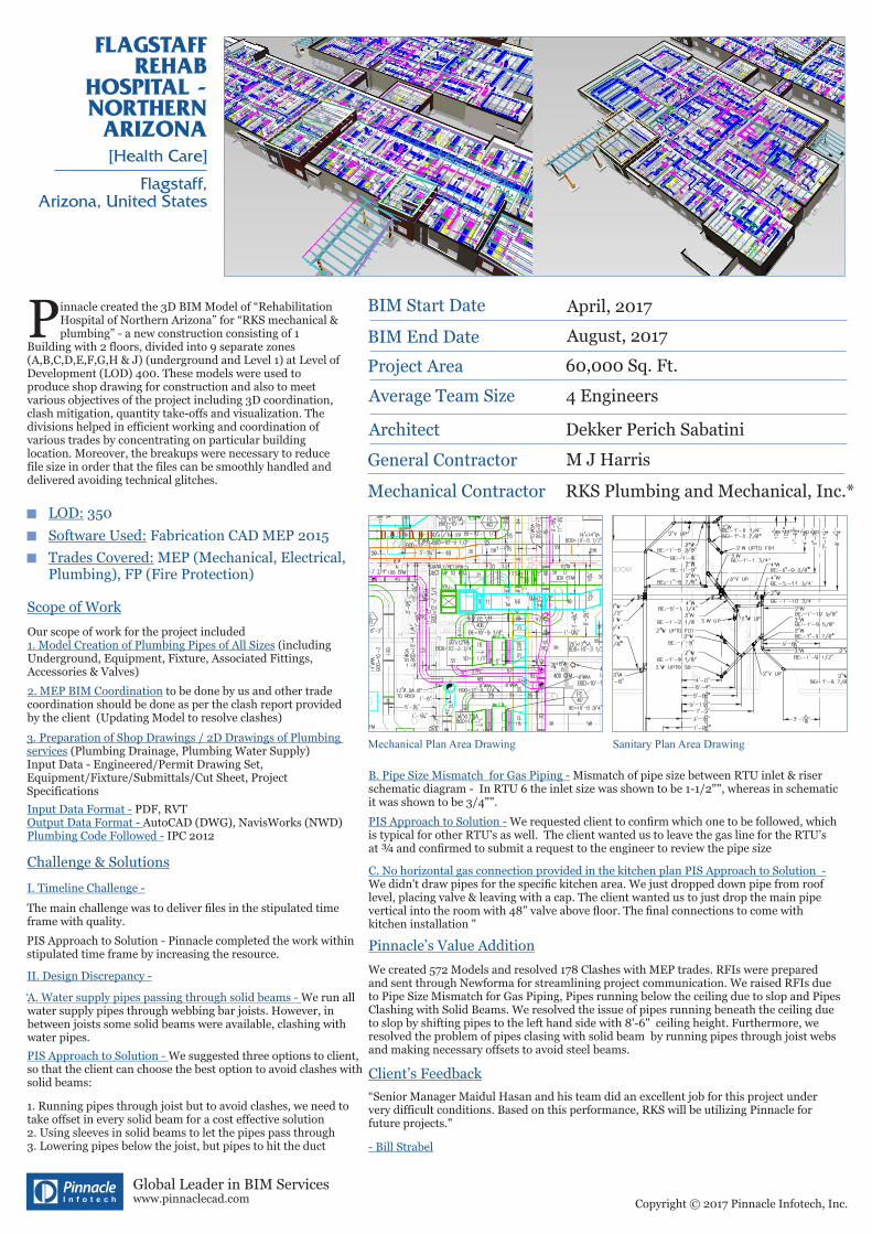
innacle created the 3D BIM Model of “Rehabilitation PHospital of Northern Arizona” for “RKS mechanical & plumbing” - a new construction consisting of 1
Building with 2 floors, divided into 9 separate zones (A,B,C,D,E,F,G,H & J) (underground and Level 1) at Level of Development (LOD) 400. These models were used to produce shop drawing for construction and also to meet various objectives of the project including 3D coordination, clash mitigation, quantity take-offs and visualization. The divisions helped in efficient working and coordination of various trades by concentrating on particular building location. Moreover, the breakups were necessary to reduce file size in order that the files can be smoothly handled and delivered avoiding technical glitches.
Pinnacle’s Value Addition
BIM End Date August, 2017
We created 572 Models and resolved 178 Clashes with MEP trades. RFIs were prepared and sent through Newforma for streamlining project communication. We raised RFIs due to Pipe Size Mismatch for Gas Piping, Pipes running below the ceiling due to slop and Pipes Clashing with Solid Beams. We resolved the issue of pipes running beneath the ceiling due to slop by shifting pipes to the left hand side with 8'-6" ceiling height. Furthermore, we resolved the problem of pipes clasing with solid beam by running pipes through joist webs and making necessary offsets to avoid steel beams.
General Contractor M J Harris
Challenge & Solutions
Software Used: Fabrication CAD MEP 2015
LOD: 350
Our scope of work for the project included (including 1. Model Creation of Plumbing Pipes of All Sizes
Underground, Equipment, Fixture, Associated Fittings, Accessories & Valves)
Trades Covered: MEP (Mechanical, Electrical, Plumbing), FP (Fire Protection)
2. MEP BIM Coordination to be done by us and other trade coordination should be done as per the clash report provided by the client (Updating Model to resolve clashes) 3. Preparation of Shop Drawings / 2D Drawings of Plumbing services (Plumbing Drainage, Plumbing Water Supply) Input Data - Engineered/Permit Drawing Set, Equipment/Fixture/Submittals/Cut Sheet, Project Specifications
Input Data Format - PDF, RVT AutoCAD (DWG), NavisWorks (NWD) Output Data Format -
IPC 2012Plumbing Code Followed -
I. Timeline Challenge -
II. Design Discrepancy -
PIS Approach to Solution - Pinnacle completed the work within stipulated time frame by increasing the resource.
A. Water supply pipes passing through solid beams - We run all water supply pipes through webbing bar joists. However, in between joists some solid beams were available, clashing with water pipes.
PIS Approach to Solution - We suggested three options to client, so that the client can choose the best option to avoid clashes with solid beams:
1. Running pipes through joist but to avoid clashes, we need to take offset in every solid beam for a cost effective solution2. Using sleeves in solid beams to let the pipes pass through3. Lowering pipes below the joist, but pipes to hit the duct
B. Pipe Size Mismatch for Gas Piping - Mismatch of pipe size between RTU inlet & riser schematic diagram - In RTU 6 the inlet size was shown to be 1-1/2"", whereas in schematic it was shown to be 3/4"".
PIS Approach to Solution - We requested client to confirm which one to be followed, which is typical for other RTU's as well. The client wanted us to leave the gas line for the RTU’s at ¾ and confirmed to submit a request to the engineer to review the pipe size C. No horizontal gas connection provided in the kitchen plan PIS Approach to Solution - We didn't draw pipes for the specific kitchen area. We just dropped down pipe from roof level, placing valve & leaving with a cap. The client wanted us to just drop the main pipe vertical into the room with 48” valve above floor. The final connections to come with kitchen installation "
The main challenge was to deliver files in the stipulated time frame with quality.
“Senior Manager Maidul Hasan and his team did an excellent job for this project under very difficult conditions. Based on this performance, RKS will be utilizing Pinnacle for future projects."
- Bill Strabel
Client’s Feedback
Mechanical Plan Area Drawing Sanitary Plan Area Drawing
Mechanical Contractor RKS Plumbing and Mechanical, Inc.*