Fishing Boat of the Waveless Hull Form
9
119 2-22(昭 和 36年 11月造 船協会秋季講演会において講演) Fishing Boat of the Waveless Hull Form By Nobutatsu Yokoyama, * Member. Summary This paper describes an experimental survey of the bulbous bow effect on the resistance with fish iing boat models of existing design and a comparative investigation between theoretical aspects based on the waveless hull form theory ignited by Prof. INUI1) and experimental results with a calculated model of known sink-source distribution ; and after advocating the necessity of an original develop- ment of unprecedented hull form for realizing actually waveless state, the paper gives some tank test Tesults of self-propulsion and of seakindliness among waves with a model of exploratory design for practical waveless boats. These preferable results may stimulate the further persuit of another effe ctive hull form for the bulb not protruding from the bow so as not to prevent from easy operation of anchoring and steering. 1 Introduction There would be found some apparent differences as shown in Table 1 and Fig. 1 in the proportion of speed, displacement and power to the ship length between fishing boats in Japan smaller than 70m. and average larger cargo liners. These statistical results since 1950 may be interpreted as there have been no other ways than powering up engine and any hydrodynamical efforts have not been paid to improve hull shape in preventing the expected speed loss resulted from the increase of ship-displace- ment by swelling out Cb to leave L unchanged on acount of the ruled restriction for LBD or GT. Conseqently the effect of full Ct, on the wave resistance must of necesity appear on the results of tank test in Fig. 2 which has been conducted by the Fishing Boat Laboratory, Fisheries Agency, with the Japanese fishing boat models built for these ten years. Considering that in Fig. 1 most operating speed at sea comes between V/•ãLg = 0.25 and 0.30 it is evident in Fig. 2 that most full ships have a peculiar fatality of climing up the confronted hump of the wave resistance and, that is, they have to waste ,excess power of some extent which might be saved by a hydrodynamical improvement for the hull form. There may possibly be two methods of the improvement ; viz, the one of reducing wave resi- 原稿 受付 昭 和 36年 6月 20日 * 水産庁漁船研究室 Table I Ratios for general boats
Transcript of Fishing Boat of the Waveless Hull Form

119
2-22(昭 和 36 年 11 月造 船協会秋季講 演会にお いて講演)
Fishing Boat of the Waveless Hull Form
By Nobutatsu Yokoyama, * Member.
Summary
This paper describes an experimental survey of the bulbous bow effect on the resistance with fish
iing boat models of existing design and a comparative investigation between theoretical aspects based
on the waveless hull form theory ignited by Prof. INUI1) and experimental results with a calculated
model of known sink-source distribution ; and after advocating the necessity of an original develop-
ment of unprecedented hull form for realizing actually waveless state, the paper gives some tank test
Tesults of self-propulsion and of seakindliness among waves with a model of exploratory design for
practical waveless boats. These preferable results may stimulate the further persuit of another effe
ctive hull form for the bulb not protruding from the bow so as not to prevent from easy operation of
anchoring and steering.
1 Introduction
There would be found some apparent differences as shown in Table 1 and Fig. 1 in the proportion
of speed, displacement and power to the ship length between fishing boats in Japan smaller than 70m.
and average larger cargo liners. These statistical results since 1950 may be interpreted as there have
been no other ways than powering up engine and any hydrodynamical efforts have not been paid to
improve hull shape in preventing the expected speed loss resulted from the increase of ship-displace-
ment by swelling out Cb to leave L unchanged on acount of the ruled restriction for LBD or GT.
Conseqently the effect of full Ct, on the wave resistance must of necesity appear on the results of tank
test in Fig. 2 which has been conducted by the Fishing Boat Laboratory, Fisheries Agency, with the
Japanese fishing boat models built for these ten years. Considering that in Fig. 1 most operating speed at
sea comes between V/•ãLg = 0.25 and 0.30 it is evident in Fig. 2 that most full ships have a peculiar
fatality of climing up the confronted hump of the wave resistance and, that is, they have to waste
,excess power of some extent which might be saved by a hydrodynamical improvement for the hull
form. There may possibly be two methods of the improvement ; viz, the one of reducing wave resi-
原稿 受付 昭和 36 年 6 月 20 日* 水産庁漁船研究 室
Table I Ratios for general boats

120 造 船 協 会 論 文 集 第 110 号
stance with a hull-shape transformation or of are
escape from making wave by submerging under
water or being dynamically lifted above; and the.
other of actively cancelling the formation of ship,
wave by a counteracting body specially designed
on the "waveless-hull form theory."
The fascinating theory has been established
by Prof. INUI (1960)1) based on his exact calcula
tion of wave-making resistance and carefull ana
lysis of the experiment, and it has predicted pos
sibility of the exsistence of a real waveless-hull
form. For the bow waves and the stern waves
respectively TAKAHEI2) and KUMANO3) (1960)
have proved the precise coincidence between the theory and the experiment conducted with two theore-
tically calculated models. And in 1961 an actual sea test was undertaken by these investigators with
80 m. passenger boat, "KURENAI MARU" and its waveless aspect was successfully filmed from a he-
licopter. In applying this fundamental theorem, however, to practical fishing boat design not only
some more details should be explored, but the substantial difference should also be recognized from
the existing design of bulbous bow. The author points out in this paper an important recognition
that the bulb would not always become a means of reducing the wave-making resistance of any kind
of ships but only when combinded with a specific form of hull which should be designed on an
entirely new stand-point it will work as an effective wave erasor at an intended speed.
The present paper gives first exemplified experiments with models of existing fishing boats either
on the usual bulbous bow design or on the "waveless theory" and shows the former a chance example
of increasing resistance and the latter in somewhat effective but imcomplete waveless condition. A
close analysis of the waves generated from every part of the existing hull proves the situation resulted
from unfavourable wave component for the counteraction. The author contributed to give some
information of potential use to practical design on thorough investigations about the wave counterac-
tion with a mathematical model, the proportion of whose dimension is quite similar to the average
fishing boat, and presented another favourable test results for a waveless trawler model of new fashion
by making the best possible use of these results.
2 Bulb for existing boats
Generally the ship waves are composed of the local disturbances at bow and stern, and the free
waves discharged behind the ship. The former is quite free from the wave resistance since they are
Fig. 1 Ratios for fishing boots ; fisheries,
inspection boat, boni-tuna long line boat,
△ trawler, ▲ the other fishing boats.
Fig. 2

Fishing Boat of the Waveless Hull Form 121
longitudinally symmetrical in ideal fluid, but the latter has much the most complicated effect on it
The elevation of the free waves ζws of ships for practical use is expressed in general form as:
( 1 )
In case that the ship is possibly represented by an equivalent source distribution m(ξ,ζ), the above
amplitude function At in (1) may become
( 2 )
Similarly the free wave elevation of the bulb may be expressed as following
( 3 )
The wave amplitude function of counteracted wave (C) and the transfer of the resultant profile (δ)
are consequently obtained as
( 4 )
where V denotes ship speed ; mi & M : strength of equivalent source and doublet ; Ti & f : draft
and depth of mi and M ; x, y, θ) : coordinate of a considering point in the fluid surface and direction
from mi or M ; Ai & β : amplitude function of ship waves and bulb. Then the resulting wave resi-
stance, therefore, will be represented by
( 5 )
When the stern wave can be put aside, the condition necessary for the least wave resistance is obvi-
ously C •¨ min., and this will be realized when
( 6 )
The composition of the summation Σ in (1) or the compornent amplitude At in (2) has much
important influence on the effectiveness of waveless counteraction as shown explicit in the fo11owing
experiments (a) and (b), and it entirely depends upon the shape of ship's lines―not only the coeffi
cients, Cp, Cm, Cw, but also the form of waterlines and bow-buttock lines, even if the case of having
the same coefficients.
(a) Ineffective example : A bulbous bow model, M-575 BB, (CF : Table II & III) of usual design
heretofore in use was prepared by
means of being transformed from
the ordinary model, M-575, by shift-
ing 10% of the original ship's volu-
me to the bulb inside the stem to
keep the displacement unchanged,
which has low prismatic coefficient'
0.575 and gives excellently low
resistance between V/•ãLg = 0.25,
and 0.30 according to the compara-
tive resistance test programmed by
TRAUNG(4) (1957), FAO, UN, and
carried out by the author(5) (1958).
Contrary to the initial anticipation
of reducing resistance the towing
Table II. Particulars of the models

122 造 船 協 会 論 文 集 第 110 号
test with the model showed a noti
ceable increase, for instance shown
in Fig. 3. By an analysis of shi
pside profiles of the resultant wave
like an example in Fig. 4, it is
clearly realised that the fact was
introduced by wrong counteraction
between the bow wave and the
relatively mislocated bulb. Besides
this model a large extruded bulb
was fitted for a comparison outside
the stem of M-575 and M-42 keep-
ing their draft as same as the ori-
ginal, both of which are much the finer models (CF : Table II & III) Cp of the latter is likewise
0.580•\than the ordinarily built nowadays and showed good results in towing and also in self-propel-
led test as mentioned before. The towing results in
Fig. 3, however, are not so appreciable as expected.
Such ineffectiveness as those must be brought by some
influential wave components of parasitic sources distri-
buted in both hulls which have been modified forced to
have quite low prismatic.
(b) Incomplete example : For the study of further
effect on existing fishing boats of full fore- and aft-
body, M-675 and M-41 (CF : Table II & III) whose Cp
are 0.675 and 0.633 are submitted to the test coupled
with a phase-adjusted bulb after the ship-side wave
examined. The test result in Fig. 3 indicates a prefe-
rable reduction at V/•ãLg =0.35 and that may be resu-
lted in on account of the cancellation of the bow wave
which represents the major component of the whole
wave generated by the rather simple-formed hull.
The more carefully, however, the water surface is observed, still the more unoverlooked wave could
be found remain and not partially cancelled wave is left. This phenomenon may be comprehended to
depend upon its incomplete waveless form of main hull.
Table III Particulars of the Bulbs
Fig. 3
Fig. 4

Fishing Boat of the Waveless Hull Form 123
The facts, (a) and (b), instruct us nothing but the importance of the developement for a peculiar
hull not having parasitic sources and of the investigation of the effect of bulb location.
3 The effect of bulb
A comprehensible frame-work for the effect of bulb on the resultant wave resistance could be given,
by the following ratio of amplitude function,
( 7 )
where b means the distance between each location of
the wave source for A and B. The effect of bulb
size and locations will be analogized by the illustra-
tion of Fig. 5 in the form of parameters, (aolL) 3lai,
f/L, cos(Kob), when Į =0 for the simplification, where
Ko=gIV2 and ao means the radius of the spherical
bulb. The truer resistance may be expressed by
superposing on these curves the other effects of
θ,fundamental terms of the other component waves
and one another's interfering terms which should di-
sappear right at the complete waveless points gene-
rally found at certain two Froude numbers. From
the above illustration it would be understood that the
complete waveless state could be realized only when b
=0 and in the incomplete counteraction there might
be even a case of resistance increasing.
These caluculated aspects are precisely proved in
Fig. 6, 7, 8 by the experiments with a mathematical
model M-43 whose lines are obtained along the strea-
mlines of flow produced by the distributed source and
sink V-m(ƒÌ,ƒÄ) as follows in the uniform stream V
without free surface :
(8) Fig. 5
Fig. 6

造 船 協 会 論 文 集 第 100 号124
and the dimension of M-43 is given in Table II & III. In the above experiment the wave resistances
are deduced by reducing the form drag from the resultant according to the Hughes method assuming
form factor as common as k =0. 60, because of the indeterminate phase of the total resistance at low
speed on account of the interaction. The turbulence of the model surface is stimulated by a row of
plate studs placed on the station of 9. 5 and the turbulent separation is maintained by stimulators of the same kind arranged on the bulb at ao/2 abaft the front end.
The calculation of the free wave produced by the source distribution (8) shows that the bow and
stern wave should be created exactly at FP. and AP. In reality, however, the distribution for M-43
running on the water surface should be modified in the approximation of second order at best to satisfy
the condition of ship surface especially under the perturbation of free wave, and in consequence the
generating point of bow or stern wave may possibly be shifted by the modification as far as the follow-ing distance afore FP. or abaft AP. assuming Fn→0 when n≧16:
(9)
where b=shift of the wave profile, ζ=elevation of the wave surface. Such tendency as the above
mentioned is also confirmed by the experiment, in which the center of bulb comes to project as far as
5% of L from FP. at a waveless point, V/√Lg=0.270.
Fig. 7
Fig. 8

Fishing Boat of the Waveless Hull Form 125
The size of the bulb should be decided both by the amplitude function of the main hull and of the
bulb in (3), where the latter could be practically replaced by a doublet, especially in spherical bulb.
For the model M-43 with U-frame line
(10)
and samely for the V-frame mode1, m2 (ζ) =1十 ζ/t
These could be 2- eneralized in the followinw form applvinff the Michell's assumption for thin ships
u∂y/∂x=W∂y/∂x→0, v=-V∂y/∂z―to the fore end of the mode1 a1~2α, where V・m means flow vo1ume
per unit time and area ; a half angle at the entrance
of water-line ; (u, v, w) a flow velocity ; (x, y, z) a
point on the surface of ship ; V the ship speed ;
F=V/•ãLg La =1/•ãKoL
(11)
And the amplitude function of a spherical bulb, the
draft of whose center is ζ=-f,
(12)
in general (13)
Since at complete waveless point B/A=1 and b =0
in (7),
(14)
Fig. 9is the example of B*/π for M-43 of u-frame,
to which (10) and (12) are applicable. From the
illustration at F=0.275, f/L=0.100
and fortunately this coincides with the experiment.
4 Waveless trawler model for
practical use
Through the foregoing investigation it would
be recognized that the effectiveness of the bulb at a designed speed depends upon the lines of the main
hull having no parasitic wave except the bow and stern (paragraph 2) and upon the size and location
of the bulb relative to the bow or stern wave(paragraph 3). The former hull form could be obtained
Fig. 9
Fig. 10
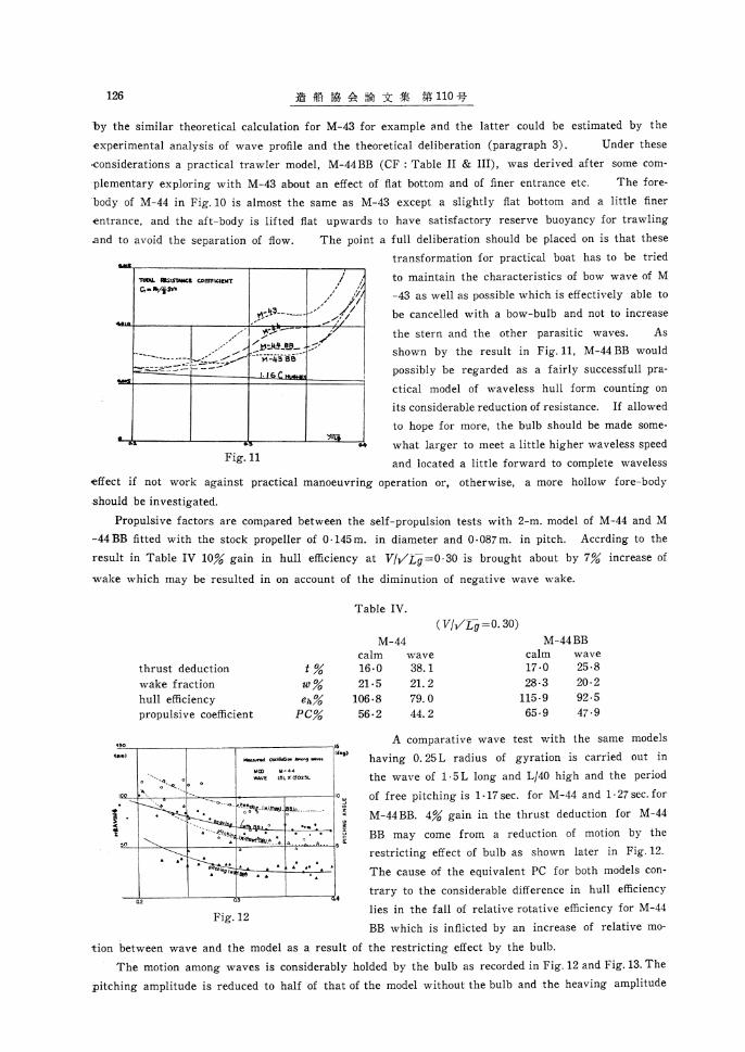
126 造 船 協 会 論 文 集 第 110 号
by the similar theoretical calculation for M-43 for example and the latter could be estimated by the
experimental analysis of wave profile and the theoretical deliberation (paragraph 3). Under these
considerations a practical trawler model, M-44 BB (CF : Table II & III), was derived after some com-
plementary exploring with M-43 about an effect of flat bottom and of finer entrance etc. The fore-
body of M-44 in Fig. 10 is almost the same as M-43 except a slightly flat bottom and a little finer
entrance, and the aft-body is lifted flat upwards to have satisfactory reserve buoyancy for trawling
and to avoid the separation of flow. The point a full deliberation should be placed on is that these
transformation for practical boat has to be tried
to maintain the characteristics of bow wave of M
-43 as well as possible which is effectively able to
be cancelled with a bow-bulb and not to increase
the stern and the other parasitic waves. As
shown by the result in Fig. 11, M-44 BB would
possibly be regarded as a fairly successfull pra
ctical model of waveless hull form counting on
its considerable reduction of resistance. If allowed
to hope for more, the bulb should be made some-
what larger to meet a little higher waveless speed
and located a little forward to complete waveless
effect if not work against practical manoeuvring operation or, otherwise, a more hollow fore-body
should be investigated.
Propulsive factors are compared between the self-propulsion tests with 2-m. model of M-44 and M
-44 BB fitted with the stock propeller of 0.145 m . in diameter and 0.087 m. in pitch. Accrding to the
result in Table IV 10% gain in hull efficiency at V/•ãLg =0.30 is brought about by 7% increase of
wake which may be resulted in on account of the diminution of negative wave wake.
A comparative wave test with the same models
having 0. 25 L radius of gyration is carried out in
the wave of 1.5 L long and L/40 high and the period
of free pitching is 1.17 sec. for M-44 and 1.27 sec. for
M-44 BB. 4% gain in the thrust deduction for M-44
BB may come from a reduction of motion by the
restricting effect of bulb as shown later in Fig. 12.
The cause of the equivalent PC for both models con-
trary to the considerable difference in hull efficiency
lies in the fall of relative rotative efficiency for M-44
BB which is inflicted by an increase of relative mo-
tion between wave and the model as a result of the restricting effect by the bulb.
The motion among waves is considerably holded by the bulb as recorded in Fig. 12 and Fig. 13. The
pitching amplitude is reduced to half of that of the model without the bulb and the heaving amplitude
Fig. 11
Table IV.
Fig. 12

Fishing Boat of the Waveless Hull Form 127
is improved to 80%. By the action of the bulb the
phase of pitching proceeds about 90 deg. ahead of the heaving that gives a visual impression of favo-
urable control over the bow motion.
5 Conclusion
The most important conclusions drawn from
the preceding investigation may be summarised
as follows :
( 1 ) The main hull should be a waveless hull form having no parasitic waves. If not at-
tainable practically, the lines should be made as
simple and natural as possible.
( 2 ) The location of bulb has a priority
order of selection for the waveless effect.
( 3 ) The size of bulb depends on the wave-less speed but it should not introduce an increase
of the form drag.
( 4 ) The effect of bulb on propulsion is more favourable than expected.
( 5 ) The performance among waves may
also be much improved.
( 6 ) The foregoing results may give hopefull suggestions except fears for manoeuvring, ancho
ring and some operations, but there is a possiblity of the solution if hollow waveless lines are
cultivated to bring back the bulb towards FP.
Acknowledgement
The author wishes to express his gratefulness to Prof. Dr. T. Inui for his continued encourage-
ment and also wishes to thank Prof. Dr. T. Takahei and Dr. M. Kumano for their helpfull supports.
The experimental work and the theoretical analysis have all been carried out at the Fishing Boat
Laboratory, Fisheries Agency, and thanks are also offered to all members of the tank for their assi-
stance.
Reference
1) INUI, TAKAHEI, KUMANO : "Tank test of the wave-making effect by bulbous bow" ZKK
108.
2) TAKAHEI : "Study on Waveless Bow" ZKK 108 & 109.
3) KUMANO : "Study on Waveless Stern" ZKK 108 & 109.
4) TRAUNG : "The Prismatic Coefficient" FISHING BOATS OF THE WORLD II.
5) YOKOYAMA, KOBAYASHI : "Resistance Test of European Wodden Trawlers" TECHNICAL
REPORT OF FISHING BOAT No. 13.
(Abr. ZKK : Journal of "ZOSEN KIOKAI", The Society of Naval Architects of Japan)
Fig. 13