First Course on Electric Drives - Electrical and Computer ...€¦ · First Course on Electric...
12
•© UMN 2010 First Course on Electric Drives Power Processing Unit (PPU) fixed form measured speed/ position speed / position Motor Electric Drive Load input command (speed / position) Power Signal adjustable form Electric Source (utility) Sensors Controller • Harnessing Wind Energy • Electric and Hybrid-Electric Vehicles
Transcript of First Course on Electric Drives - Electrical and Computer ...€¦ · First Course on Electric...

•© UMN 2010
First Course onElectric Drives
Power Processing Unit (PPU)fixed
form
measured speed/ position
speed /
position
Motor
Electric Drive
Load
input command
(speed / position)
Power
Signal
adjustable
formElectric Source
(utility)
Sensors
Controller
• Harnessing Wind Energy
• Electric and Hybrid-Electric Vehicles

•© UMN 2010
Windmills: Example of an Integrated System
0 69010 60
VHz
34.5kV
161kV
Power ElectronicsConverters
V
Time0
60Hz
Low-VoltageRide-Through
Generator
690V
•© UMN 2010
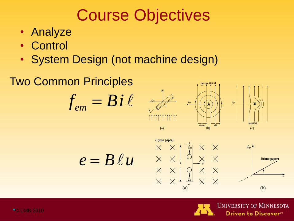
Course Objectives• Analyze
• Control
• System Design (not machine design)
Two Common Principles
emf Bi
(a) (b)add
subtract
external fieldB
emf
add
subtract
external fieldB
emf
resultant
emf
resultant
emf
(c)
i
emf
B
i
emf
B
e B uqf
u
(into paper)B
qf
u
(into paper)B
(b)(a)
qf
qf
u
(into paper)B
qf
qf
u
(into paper)B
•© UMN 2010
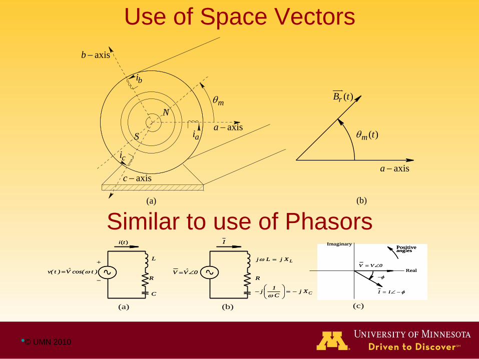
Use of Space Vectors
(a) (b)
axisc
axisa
axisb
N
S
bi
ai
ci
m
( )m t
( )rB t
axisa
Similar to use of Phasors
(a) (b)
( )i t
ˆV V 0
L
R
C
I
Lj L j X
R
C
1j j X
C
ˆv( t ) V cos( t )
( )i t
ˆV V 0
L
R
C
I
Lj L j X
R
C
1j j X
C
ˆv( t ) V cos( t )
Im
Z
cjX
R
LjX
Re0
Im
Z
cjX
R
LjX
Re0
(c)
Imaginary
Real
Positiveangles
I I
V V 0
Imaginary
Real
PositiveanglesPositiveangles
I I
V V 0
•© UMN 2010
(a) (b)
rB
m
axisa
si
N
S
ˆsI
magnetic axis of
equivalent
winding
axisc
axisa
axisb
N
S
bi
ai
ci
m
rB
o90
'a
a
si
at t
o90
.
. .
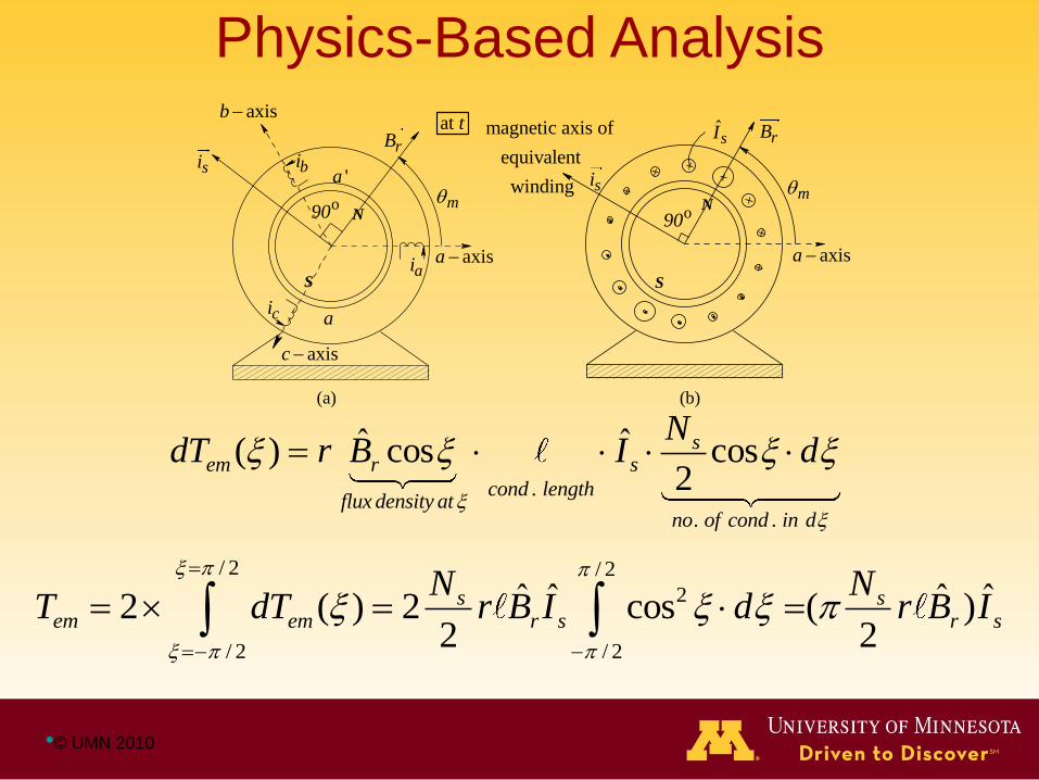
ˆ ˆ( ) cos cos2
sem r s
cond lengthflux density at
no of cond in d
NdT r B I d
/ 2 / 2
2
/ 2 / 2
ˆ ˆ ˆ ˆ2 ( ) 2 cos ( )2 2
s sem em r s r s
N NT dT r B I d r B I
Physics-Based Analysis

•© UMN 2010
Topics• Designing for the Mechanical Load
• DC Motor Drives
• Permanent Magnet AC Drives
• Induction Motor Drives: Steady State and V/f Control
• Stepper and Switched-Reluctance Drives
• Feedback Control
• Power Quality Considerations
Textbook
• Presentation Slides
• Solutions Manual

•© UMN 2010
Electric Drives Lab
Drives Board for Motor and Active Load (Generator) 42- V Motor Set
• Low-cost; 42-V no Shock Hazard!
• DSP Controlled; easy to use
• Active Load Allows Experiments otherwise not possible
• Very Popular with students!

•© UMN 2010
Graduate-Level Course
d-q axes control
Applications in windmills, hybrid and electric vehicles,
robotics and factory automation
Control of Drives in Windmills
Kpp
+ Kip/s
+
+-
Pord
Pelec
Trip
flagPitch Control
1
____
1+ sTp
Pmech
1
____
2H
Paccel 1
____
s
ref
Wind
Power
Model
Wind
speed
+
-
+
-
Pitch
Anti-windup on
Pitch Limits
min
& d /dt min
Kpfreq
+ Kifreq
/s
Torque ControlPmax
Pelec +
Kpc
+ Kic/s
Pmax
-
Pmax
Pitch
Compensation
X1
____
1+ sTpc
P min
Anti-windup on
Power Limits
Over/Under
Speed Trip
Logic:
if
speed > max
or
speed < min
then
set trip flag = true
endif
Power Order
cmd
err
max & d /dt
max

•© UMN 2010
t
t0
0
Load Torque
Seamless Transition to Dynamic Control and
Encoderless Operation
Speed

•© UMN 2010
a axis
b axis
c axis
m
ia
ib
ic
iA
iC
iB
A axis
B axis
C axis
m
a axis
b axis
c axis
m
ia
ib
ic
iA
iC
iB
A axis
B axis
C axis
m
•© UMN 2010
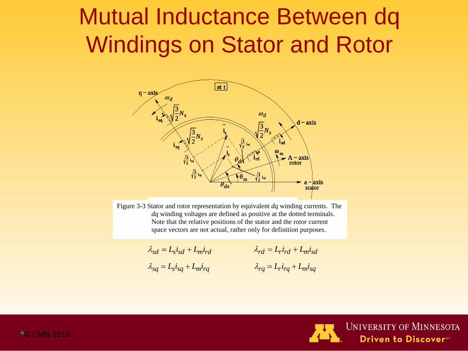
Mutual Inductance Between dq
Windings on Stator and Rotor
a axisstator
A axisrotor
d axis
m
isd
isq
q axisat t
i rq
ird
m
is
ir
3
2isd
3
2isq
3
2irq 3
2ird
d
d
da
dA
3
2sN
3
2sN
3
2sN
Figure 3-3 Stator and rotor mmf representation by
equivalent dq winding currents.
a axisa axisstator
A axisA axisrotor
d axisd axis
m
m
isdisd
isqisq
q axisq axisat tat t
i rqi rq
irdird
m
m
is
is
ir
ir
3
2isd
3
2isd
3
2isq
3
2isq
3
2irq
3
2irq 3
2ird
3
2ird
d
d
da
dA
3
2sN
3
2sN
3
2sN
Figure 3-3 Stator and rotor mmf representation by
equivalent dq winding currents.Figure 3-3 Stator and rotor representation by equivalent dq winding currents. The
dq winding voltages are defined as positive at the dotted terminals.
Note that the relative positions of the stator and the rotor current
space vectors are not actual, rather only for definition purposes.
sd s sd m rdL i L i
sq s sq m rqL i L i
rd r rd m sdL i L i
rq r rq m sqL i L i
•© UMN 2010
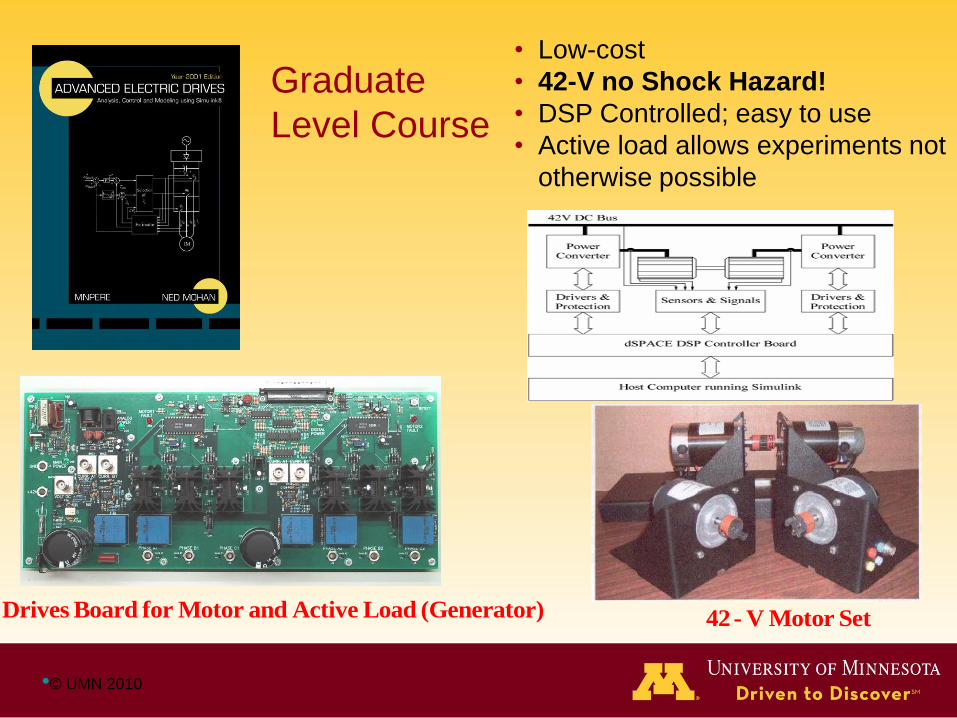
Drives Board for Motor and Active Load (Generator) 42- V Motor Set
Graduate
Level Course
• Low-cost
• 42-V no Shock Hazard!
• DSP Controlled; easy to use
• Active load allows experiments not
otherwise possible