Position and Speed Feedback Devices for variable speed drives ...
68
An Engineering Guide to Position and Speed Feedback Devices for variable speed drives and servos
Transcript of Position and Speed Feedback Devices for variable speed drives ...

An Engineering Guide to
Position and Speed Feedback Devices for variable speed drives and servos

This guide is one of a series covering subjects such as harmonics, safety features, EMC, feedback devices, industrial communications and motion control.
These can be accessed via www.controltechniques.com/guides.

www.controltechniques.com 3
Contents
Page.
1 Position and speed feedback 5
1.1 General 5
1.2 Typical applications 5
1.3 Feedback technologies 6
2 Motor feedback device selection and properties 7
2.1 Speed and position feedback 7
2.2 Absolute position feedback range 7
2.3 Position resolution 7
2.4 Position accuracy 9
2.5 Speed resolution 9
2.6 Speed accuracy 9
2.7 Environment 9
2.8 Maximum speed 10
2.9 Electrical noise immunity 11
2.10 Distance between the feedback device and the drive 11
2.11 Additional features 11
3 Feedback sensors 12
3.1 Tacho-generators 13
3.2 Resolver 17
3.3 Hall effect sensors 20
3.4 Quadrature incremental encoders 25
3.5 Quadrature incremental encoder with commutation signals 30
3.6 SinCos incremental encoders 34
3.7 Serial communication encoders 39
3.7.1 EnDat (Heidenhain) encoders 41
3.7.2 SinCos Hiperface (SICK/Stegmann) 45
3.7.3 Synchronous Serial Interface SSI 48
3.8 SinCos encoder with sinusoidal commutation 53
4 Feedback resolution 55

4 www.controltechniques.com
Page.
5 Emerging technologies 57
5.1 BiSS encoders 57
5.2 ISI encoders (TR electronics) 58
5.3 Wireless encoders 60
6 Glossary 61
7 Acknowledgement 63
8 Appendix 63

5www.controltechniques.com
1. Position and speed feedback
1.1 General
The purpose of this document is to provide the reader with useful information on feedback devices fitted to electrical motors that are connected to electronic variable speed drives (drives).
This document will cover feedback types, common terminology, resolution and positional accuracy expected from encoders.
In systems where precise control of position or speed is important, a position or speed sensor is required. Although there are many different types of position and speed sensors available, the devices described in this guide are limited to those that are likely to be used with a modern variable speed drive. To control an AC motor it is necessary to determine the speed of the motor and the position of the flux in the motor. Various sensorless control schemes are available, which can estimate these quantities by measuring the motor currents, however, for higher quality performance a position or speed feedback device is normally used. To control a DC motor it is only necessary to determine the speed of the motor. Again, sensorless control is possible by measuring the armature current and voltage, but for accurate speed control a speed feedback device is still required.
It should be remembered that whilst sensorless control has many attractions, in a large number of practical systems it is necessary to have a direct measurement of the motor shaft motion as part of an outer control loop or safety case. Sensors are therefore an important element of many drive systems and play a critical part in determining the performance of high performance systems.
It should also be noted that a significant number of site problems with drive systems are associated with either the selection or installation of the position or speed sensor.
1.2 Typical applications
Feedback devices are used in any application requiring high performance at the motor shaft, requiring closed loop operation from the drive or exact positioning. Following are some of the applications where feedback devices are often used: ➜ Sheer presses ➜ Robotics ➜ Transport systems ➜ Printing applications ➜ CNC (Computer numerical control) machines ➜ Lifts / hoists ➜ Test rigs

6 www.controltechniques.com
The following factors define the type of the feedback device that is chosen:
➜ Feedback accuracy required ➜ Cost ➜ Robustness in an environment ➜ Cable length ➜ Noise immunity ➜ Number of cables carrying feedback data
1.3 Feedback technologies
Feedback signals come in the following formats: ➜ Analog signals ➜ Digital pulse train signals ➜ Serial communication ➜ Combination of above
Some devices use a combination of different types of signals to provide incremental and absolute position.
Typical devices in each of the 3 categories are as follows:
Analog devices ➜ Tacho-generators ➜ Resolvers ➜ SinCos encoders ➜ Analog Hall effect sensors
Digital pulse train devices ➜ Incremental encoders ➜ Digital Hall effect sensors
Serial communication devices ➜ Hiperface encoders ➜ EnDat encoders ➜ SSI encoders ➜ BiSS encoders

7www.controltechniques.com
2 Motor feedback device selection and properties
The following areas should be taken into consideration when selecting an encoder.
2.1 Speed and position feedback
If both position and speed feedback are required, as is the case in AC motor control, it is possible to use a sensor that gives position feedback and then derive speed feedback as a change of position over a fixed sample time. If speed feedback alone is required, as is the case in DC motor control, it is possible to use a device that gives speed feedback only. Most types of position feedback sensor are available to measure either rotary or linear movement.
For rotary motor control a rotary feedback device is normally used, however, for linear motor control a linear feedback device is more suitable. Throughout the rest of this guide, the descriptions given relate mostly to the rotary version of each type of position sensor.
2.2 Absolute position feedback range
The absolute position feedback range defines the movement over which it must be possible to uniquely determine the position. Table 2-1 gives some examples of the absolute position feedback range required for different applications.
Table 2-1 The feedback range required for different applications
Application Absolute position feedback rangeRotary induction motor control Incremental position only. Absolute position not required.
Rotary synchronous motor control including PM Servo
Absolute position range equivalent to one electrical revolution (i.e. 120° of mechanical rotation for a 6-pole motor).
Rotary position controlAbsolute position range equivalent to the movement between all the required positions. If this involves more than one turn then a multi-turn position sensor is required.
Linear induction motor Incremental position only. Absolute position not required.
Linear synchronous motor control Absolute linear position range equivalent to one motor pole pitch.
Linear position controlAbsolute linear position range equivalent to the movement between all the required positions.
Some position feedback sensors can provide absolute position information as soon as they are powered up. Others may need to be moved to a home position and then track the change of position from the homing point to give absolute position. In this case the absolute position is not available immediately when the device is powered up.
2.3 Position resolution
The position resolution and position accuracy of a feedback device should not be confused. The resolution defines the nominal position movement required for the device to detect a change of position. The accuracy, on the other hand, is a measure of the maximum deviation of the feedback position from the actual position. An analog feedback signal from a potentiometer used to measure position has almost infinite resolution, but the resolution of an

8 www.controltechniques.com
Probably the most notable limit imposed by position resolution is the maximum possible gain in a speed control system where the speed is derived from a position feedback device by calculating the position change over a fixed sample period. An encoder rotating at a constant speed may not necessarily produce an exact integer number of pulses over each sample period. The result is that the pulses counted each time will vary between the integer value above and below the mean number of counts per sample. In the example given in Figure 2-1 the mean number of counts per period is 4.3, but either 4 or 5 counts are seen during each period. This gives rise to a ripple in the speed feedback which is equivalent to a speed that gives one encoder count per sample period. The speed controller tries to correct for the ripple seen in the feedback and generates a high frequency torque component that produces acoustic noise. The ripple and noise increase as the gain of the speed controller is increased. The speed that gives one count per sample period is equivalent to a movement of R / 360 revolutions per period, where R is the resolution of the feedback device in degrees. Therefore if the sample time (Ts) is in seconds this speed is given by:
Equation 1 Speed in revolutions per second (rps) = (R / 360) / Ts and so
Equation 2 Speed in revolutions per minute (rpm) = ((R / 360) / Ts) x 60 = R / (6 x Ts)
The speed given in Equation 2 is the control loop speed feedback ripple in min-1 from a position feedback device, with a resolution of R degrees per revolution, when the speed measurement is made with a sample time of Ts seconds. The value calculated is not the speed ripple seen at the motor shaft. The motor inductance and the load inertia absorb the majority of the ripple with only a small component remaining. The value can be used to compare feedback devices. It is a popular misconception that this speed ripple changes with actual speed, and that it is worse as the speed approaches zero. This is not the case because the speed ripple is always defined by Equation 2 except in the unlikely case when the speed remains absolutely constant at a level where an exact integer number of counts occur during each sample period.
As can be seen from Equation 2, speed feedback ripple can be reduced by increasing the sample time, which has a detrimental effect on the speed controller response, or increasing
encoder is limited by the number of pulses produced for a given movement. It is important to note that the position accuracy is almost always lower than the resolution.
Figure 2-1 Speed feedback derived from an encoder
Maximum = 5 counts per sample
Minimum = 4 counts per sample
Mean = 4.3 counts per sample
Speed feedback
Encoder pulse

9www.controltechniques.com
the resolution of the position sensor which tends to add cost. Pulse width measurement is sometimes used in attempt to reduce speed feedback ripple, however, this is not recommended as the system becomes non-deterministic at low speeds and the electrical noise that is usually present on the pulse edges, due to power electronic switching in the drive, can give rise to large fluctuations in the speed feedback.
2.4 Position accuracy
Position accuracy is a measure of the maximum deviation of the measured position from the actual position. As would be expected, this limits the accuracy of a position control system using the feedback device. However, deviations in the position, in addition to those generated by limited resolution, can contribute to speed feedback ripple when position change over a fixed sample period is used to derive speed feedback. This becomes more noticeable with a high resolution feedback device such as a SinCos encoder.
2.5 Speed resolution
The only speed feedback device that will be considered is a DC tacho-generator. This is an analog feedback device, and so speed feedback resolution of the device itself is not a problem. However, most modern variable speed drives use digital control, and so the speed feedback signal is fed into the speed controller via an analog to digital (A to D) converter, which imposes a limit on the speed feedback resolution. Therefore the speed resolution of the system is limited by the A to D converter resolution in the drive.
It may seem counter-intuitive, but the resolution of the mean speed feedback derived by measuring position change over a fixed sample time from a position feedback device such as an encoder can give extremely high mean speed feedback resolution. If a speed controller which includes an integral gain is used, the integral term accumulates the speed error between the speed reference and speed feedback. This has the effect of extending the sample period over which the speed is measured to the time for which the system has been enabled and extending the sample time increases the resolution of the mean speed feedback. The resolution of such a system is only limited by the resolution of the speed reference and not the speed feedback.
2.6 Speed accuracy
Speed feedback accuracy is usually worse than speed feedback resolution. The speed accuracy of a speed feedback device such as a tacho-generator, is defined by its absolute accuracy and non-linearity. Where speed feedback is derived from a position sensor, such as an encoder, the main effect on the speed accuracy is the accuracy of the sample period, which in a digital system is defined by the system clock. Where this clock is produced by a quartz crystal, accuracies of 100ppm (0.01%) are easily achievable. It should be noted that this is a percentage of the actual speed and not full scale speed, therefore the accuracy in rpm or rads-1 improves as the actual speed is reduced.
2.7 Environment
Consideration must be given to the environment in which a position or speed sensor is to operate. If the device is to be mounted on to a motor it is likely that the environment will be hot and

1 0 www.controltechniques.com
subject to mechanical vibration. Other effects such as axial movement of the motor shaft and radial eccentricity of the mounting should also be taken into account. Although most industrial feedback devices are sealed, it is possible for contamination to occur. This can be a problem for optical encoders with fine lines on the glass disc, where gases and dust can degrade the performance of the device. In the presence of moisture or corrosive gasses, corrosion of the sensor and any associated signal conditioning electronics can be an issue. Special designs of sensor are available that are protected against some of the milder corrosive contaminants.
Providing a seal against contamination is more difficult with a linear encoder, and so care has to be taken in the design and mounting of the device. Unlike an encoder, a resolver can be used without problems in a hot environment with high levels of vibration and contamination.
2.8 Maximum speed
There is always a maximum mechanical operating speed for any position or speed sensor above which the device would be damaged.
The maximum speed is also limited by the feedback device bearing assembly. The feedback device manufacturer usually specify this limit in their datasheet. The life time of the bearing decreases with an increase in operating speed when operating above permissible load. Figure 2-2, taken from a Heidenhain ROC/ROQ/ROD 400 feedback encoder datasheet, shows how the bearing life can be affected with increase in operating speed and above permissible load.
Figure 2-2 Bearing life time
Bear
ing
lifet
ime ➤
Shaft speed [rpm] ➤
Bearing lifetime is shaft subjected to load
40 000
0 16 00014 00012 000100008000600040002000
35 000
30 000
25 000
20 000
15 000
10 000
5 000
0
F = 40 N F = 60 N Ø 6 Ø 10
The accuracy of the feedback from some sensors such as tacho-generators or SinCos encoders can degrade above a speed that is lower than the maximum mechanical operating speed.
Note also that the processing electronics in a drive may give reduced accuracy or cease to work at all as the frequency of the signals from a digital encoder, SinCos encoder or resolver increases with the mechanical speed of the sensor. The maximum frequency for an encoder input will be defined by the variable speed drive manufacturer.

1 1www.controltechniques.com
2.9 Electrical noise immunity
Considerable electrical noise can be generated by the switching action of the power electronic devices in a variable speed drive. Careful system design can prevent this noise from affecting other equipment including position or speed sensors. Even so, the noise immunity of the different types of feedback device should be considered. Analog devices are likely to be more prone to disturbance than digital devices, and so a SinCos encoder with 1V peak-to-peak sine wave output signals is less immune to electrical noise than a digital encoder producing 5V square waves.
Although a tacho-generator produces analog signals, the type of device traditionally used with a DC motor drive generates a relatively high voltage, and so it is reasonably noise immune.
2.10 Distance between the feedback device and the drive
The following list details some of the problems that may occur as the distance between the feedback device and the drive is increased:
1. Active sensors such as encoders require a significant amount of power supply current to drive their internal circuits and the terminations on their output signals at the receiving end. The voltage drop in the power supply conductors may reduce the voltage at the encoder to a level where the device does not function correctly.
2. The resolution of a SinCos encoder is reduced as the sine wave signal magnitude is reduced. Again, voltage drops in the conductors can cause these signals to be reduced.
3. Sensors which produce sine wave outputs, such as resolvers, will suffer from phase shifting if very long cabling is used.
4. Some encoders use synchronous digital communications. As the clock frequency and distance are increased, skew between the clock and data can become a problem. The clock is generated by the drive and the skew occurs on the data transmitted back from the encoder. It is possible to electronically measure the line length between the drive and the encoder, and adjust the sampling point for the data at the drive end to counteract this problem. Otherwise, the distance between the drive and the encoder must be limited as the clock and data rate are increased.
2.11 Additional features
The following additional features are available in some encoders:
1. Automatic recognition of the encoder.
2. Non-volatile storage within the encoder, which allows the user to store data such as motor or machine parameters.
3. Advanced error detection providing information about the state of the encoder.
4. The facility to offset the encoder zero position electronically.

1 2 www.controltechniques.com
3 Feedback sensors
The table below is shown at the start of each feedback device section to summarise the features that the feedback device offers and on what motor technology it is commonly used.
DC brush rotary
DC brushless rotary
AC induction rotary
AC brushless rotary
AC brushless linear
Used on
Speed
Position
Absolute
Commutation
How to interpret the table:
Motor technology:
➜ DC brush rotary – DC commutated motor including their larger industrial counterparts ➜ DC brushless rotary – Permanent magnet rotary DC brushless synchronous servo motors also known as DC trapezoidal ➜ AC induction rotary – AC asynchronous induction motors both standard and high performance constructions (Spindle motors, etc.) ➜ AC brushless rotary – Permanent magnet rotary AC brushless synchronous servo motors ➜ AC brushless linear – Permanent magnet linear AC brushless synchronous servo motors
Feedback functionality:
➜ Used on – indicates if the feedback device is used on this motor technology ➜ Speed – If this feedback type is used does it offer this functionality? ➜ Position – If this feedback type is used does it offer this functionality? ➜ Absolute – Single E – Absolute position in an electrical cycle, ie the device uses commutation tracks Single M – Absolute position available in one mechanical cycle/revolution Multi - Absolute position available in several mechanical cycle/revolution ➜ Commutation – Does this device offer commutation information at start-up?
General:
➜ NA – Not applicable
1 3www.controltechniques.com
3.1 Tacho-generators
DC brush rotary
DC brushless rotary
AC induction rotary
AC brushless rotary
AC brushless linear
Used on Yes No Yes No No
Speed Yes Yes
Position No No
Absolute NA NA
Commutation NA NA
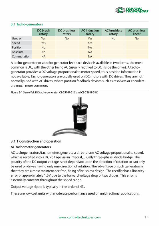
A tacho-generator or a tacho-generator feedback device is available in two forms, the most common is DC, with the other being AC (usually rectified to DC inside the drive). A tacho-generator provides a DC voltage proportional to motor speed, thus position information is not available. Tacho-generators are usually used on DC motors with DC drives. They are not normally used with AC drives, where position feedback devices such as resolvers or encoders are much more common.
Figure 3-1 Servo-Tek DC tacho-generator CS-7514F-51C and CS-7561F-51C
3.1.1 Construction and operation
AC tachometer generators
AC tachogenerators/tachometers generate a three-phase AC voltage proportional to speed, which is rectified into a DC voltage via an integral, usually three–phase, diode bridge. The polarity of the DC output voltage is not dependant upon the direction of rotation so can only be used on drives having only one direction of rotation. The advantage of such generators is that they are almost maintenance free, being of brushless design. The rectifier has a linearity error of approximately 1.5V due to the forward voltage drop of two diodes. This error is essentially constant throughout the speed range.
Output voltage ripple is typically in the order of 4%.
These are low cost units with moderate performance used on unidirectional applications.

1 4 www.controltechniques.com
DC tacho-generators
The DC tacho-generator uses the same principles of magnetic coupling as the AC tacho-generator. The DC tacho-generator, however, has a steady (non-fluctuating) primary magnetic field. This magnetic field is usually supplied by permanent magnets. The amount of voltage induced in the rotor winding is proportional to the number of magnetic flux lines cut. The polarity of the output voltage is determined by the direction in which the rotor cuts the lines of magnetic flux.
The physical construction and operation of the DC tacho-generator is very similar to a DC generator. The only difference is that the DC tacho-generator is much smaller in size and is linked mechanically to the servo motor or load instead of to a prime mover.
Figure 3-2 Typical DC tacho-generator construction
Brush assembly
Field assemblyArmature assembly
Bearing
3.1.2 Output signals
An AC tacho-generator outputs a sine wave whose amplitude is directly proportional to the speed of the rotating machinery. The windings produce a distorted AC waveform, with each peak voltage representing the teeth of the rotating shaft. The amplitude and frequency of the tacho signal may vary depending on the reference signal provided. This AC signal can be later converted to DC using rectifiers and the amplitude of the DC signal represents the speed of the rotating shaft, which can be used as a speed feedback for drives.
Unlike an AC tacho-generator, a DC tacho-generator outputs a DC voltage directly, whose amplitude is directly proportional to the speed of the rotating shaft.

1 5www.controltechniques.com
3.1.3 Capability
The advantages of using a tacho-generator are as follows:
➜ Tacho-generators are robust against vibration and shock loads. They have a wide operating temperature range and are the most common feedback device on industrial DC motor drives
➜ The construction and electronics are quite simple
➜ Requires only two cables to interface it to the drive
The disadvantages of using a tacho-generator are as follows:
➜ DC tachometers are relatively expensive and the brushes require maintenance. They are usually replaced by other lower cost feedback devices on industrial AC motor drives
➜ A tacho-generator gives speed feedback only. The position of the shaft is unknown
➜ The signal from an AC tacho-generator has to be converted to DC using rectifiers to use it as speed feedback for drives. The AC tacho-generator can only be used for unidirectional applications where only moderate performance is required, as the rectified diodes give a voltage error and the speed signal contains significant ripple
➜ A DC tacho-generator gives a DC voltage proportional to motor speed and is usually rated as Volts per 1000 rpm (V/krpm). Industrial versions tend to be on the order of 20 to 120 V/krpm and not linear below 500 rpm. DC tacho-generators used on brushed DC servo motors tend to be below 10 V/krpm and have high quality silver impregnated carbon brushes to give very good low speed performance and offer good linearity below 50 rpm
➜ A tacho-generator produces a voltage output proportional to speed. A voltage drop is usually expected with long cables
➜ Due to the analog nature of the feedback, it is prone to noise at lower voltage feedback output and screened cables are highly recommended
➜ The temperature coefficient for a tacho-generator specifies the percentage change of the output voltage for a given change in temperature. The lower this value the more stable the speed feedback is with variations in temperature. Generally the cost of a tacho-generator increases with improved temperature coefficient. Care should be taken not to exceed the maximum allowed loading on the device as this will elevate the internal temperature and cause higher than expected deviation from the nominal output voltage

1 6 www.controltechniques.com
Table 3-1 Characteristics of different DC tacho-generator designs
TypeTypical temperature
coefficient per degree (K)
Description
Uncompensated 0.2% Basic design using low cost magnets
Compensated 0.05%
Thermistor based compensation is used to improve a low cost uncompensated design. The output impedance is higher than more expensive types and the temperature compensation range is normally limited.
Stable 0.02% More stable magnets are used.
Ultra-stable 0.01%More stable magnets are used with a compensating alloy in the magnetic field circuit to improve the temperature stability.
➜ The speed linearity, typically 0.1% to 0.2%, is specified up to the maximum operating speed. If this range is exceeded the linearity degrades because of aerodynamic lift of the brushes, hysteresis losses, armature reaction and saturation. The speed accuracy is normally lower than the linearity, and is typically in the range from 1% to 2%.
3.1.4 Drive interface
The tacho signal from a tacho-generator is a DC voltage signal proportional to the speed of the motor. The signal from a tacho-generator can be used as speed feedback by drive. There is a dedicated tacho-generator input on Mentor MP, Mentor I, Mentor II and Maestro. Mentor MP can accept the signal from an AC or a DC tacho-generator directly and filtering is also available within the drive for smoother speed feedback. Mentor I, Mentor II and Maestro can only accept signal from DC tacho-generator.
The signal can only be used as a reference speed signal but not as a primary feedback signal when used with Unidrive SP or Digitax ST. With Unidrive SP and Digitax ST this signal can be fed to the drive using one of the analog inputs on the drive (control terminal 5, 6, 7 and 8). The output of the tacho-generator must be checked for compatibility with the analog input of Unidrive SP or Digitax ST before connecting. A tacho-generator cannot be used on Epsilon EP drives.
Unidrive SP Digitax ST Mentor MP Epsilon EPStandard ✔
Option
Usually two cables run through a tacho-generator for feedback; one positive and one negative DC input to the drive. A screened cable is highly recommended as the output from the tacho-generator is an analog signal.
Total number of connections 2
Drive to feedback device 0
Feedback device to drive 2 (+ input and - input to the drive)

1 7www.controltechniques.com
3.2 Resolver
DC brush rotary
DC brushless rotary
AC induction rotary
AC brushless rotary
AC brushless linear
Used on No No Yes Yes No
Speed Yes Yes
Position Yes Yes
Absolute NA Single M*
Commutation NA Yes
* Resolvers with a number of poles greater than 2 only provide Single E absolute position information.
A resolver provides speed as well as position feedback. It is a very robust device and gives a wide temperature range.
3.2.1 Construction and operation
A resolver is like a rotating transformer which consists of a primary winding mounted on a rotor shaft and two secondary windings mounted on a stator assembly. The primary winding is also called 'excitation winding' because an excitation voltage is applied to the primary winding. The two secondary windings are oriented 90° to one another. A constant frequency AC signal is applied to the excitation winding called the 'excitation signal'. This produces a corresponding signal on the secondary windings whose peak signal varies in amplitude as the shaft rotates which gives a continuous angular position of the shaft. The peak amplitude of the signal on secondary windings varies because the effective turns-ratio varies as the primary winding rotates. The output signals on the secondary windings are 90° out of phase with each other and hence one of them can be called sine and the other cosine.
From the sine and cosine signals the position of the shaft can be determined. This is done external to the resolver feedback using conversion electronics. The sign of the sine and cosine signal is used to determine in which quadrant (0° to 90°, 90° to 180°, 180° to 270° or 270° to 0°) the shaft is located. Using an A to D converter this information is converted into digital format. The most significant two bits represent which quadrant the shaft is in. The remaining bits represent the angle the shaft is at from the edge of the quadrant. On every power-up, the electronics can get the current shaft position by reading the sine and cosine signals for feedback. 14 bits are typical for a resolver input, which would give a resolution of 212 or 4096 PPR. For one mechanical revolution of the motor 16,384 CPR (214) discrete positions are available.
Resolvers are available with different primary and secondary winding turn-ratio. It usually comes in 2:1 or 3:1 input to output turns-ratio. Some resolver manufacturers mount the primary windings on the stator assembly and secondary winding on the rotating shaft, but the theory of operation is still the same.
Resolvers are available with various numbers of poles. If the number of poles of the resolver is not 2, then the resolver can only work with a motor that has the same number of poles (e.g. a 6-pole resolver with a 6-pole motor). A 4-pole resolver will give two electrical cycles within one mechanical revolution. Therefore, a 4-pole resolver cannot provide absolute position (mechanical) since the signals are identical at 2 positions within one 360° mechanical turn. Similarly, 6-pole, 8-pole, etc. resolvers cannot provide absolute position (mechanical) for the same reason.

1 8 www.controltechniques.com
Figure 3-3 Brushless 2-pole resolver
Stator windings
Sine feedback signal to drive
Cosine feedback signal to drive
Excitation signal from drive
Rotor winding
3.2.2 Output signal
Resolver feedback requires an excitation signal from the drive. The Unidrive SP fitted with an SM-Resolver module provides a 6 kHz 4Vrms or 6Vrms sine wave for excitation which is fed to the resolver. The 6 kHz 4Vrms or 6Vrms is selected depending on turns ratio of the resolver transformer (6Vrms for 3:1 and 4Vrms for 2:1 turns ratio). The output of a resolver is a 2Vrms modulated sin and cos wave as shown in Figure 3-4. The absolute position of the shaft can be obtained using the sin and cos signals.
Figure 3-4 Sin and Cos output of a 2-pole resolver
90° 180° 270° Zero positionZero position
Carrier in phasewith excitation
COS(secondary)
SIN(secondary)
Excitation(primary)
MotorUphase
Resolverposition
Carrier in phasewith excitationCarrier in anti-phase with excitation
Carrier in anti-phase with excitationCarrier in phase with excitation

1 9www.controltechniques.com
3.2.3 Capability
Some of the advantages of using a resolver are:
➜ The resolver itself contains no electronic components and therefore it can withstand hot temperature as high as 175°C and low temperature as low as -55°C. A resolver is the ideal reliable feedback device for use in harsh environmental conditions as there are no electrical or mechanical connections between rotor and stator.
➜ The resolver rotor is mounted directly on the motor shaft, giving a robust measurement system for velocity and position signals.
Some of the disadvantages of using a resolver are:
➜ A resolver is one of the cheapest devices around but the electronics required for analog to digital conversion (SM-Resolver module) can make the whole package expensive.
➜ The resolution of a resolver is dependent on the maximum speed required and the resolver equivalent lines per revolution (ELPR). Table 3-2 lists the possible resolver ELPR, the resolution available and the maximum speed available when they are used with Unidrive SP and Digitax ST.
Table 3-2 Resolver feedback resolution and maximum motor speed
ELPR Feedback Resolution Maximum Speed256 1024/rev 40,000rpm
1024 4096/rev 13,200rpm
4096 16384/rev 3,300rpm
3.2.4 Drive interface
Unidrive SP Digitax ST Mentor MP Epsilon EPStandard
Option ✔ ✔
An SM-Resolver module is required to interface a resolver with a Unidrive SP or Digitax ST drive. The SM-Resolver module will only provide speed feedback when it is selected as the source of the drive speed/position feedback. Hence, it is not possible to use resolver feedback as a speed reference.
The SM-Resolver option module will allow for resolvers with the following specification to be used with Unidrive SP or Digitax ST:
Input impedance of primary coil of resolver transformer: >85Ω at 6kHz
Turns ratio of the resolver transformer: 3:1 or 2:1 (input : output)
Number of poles: 2, 4, 6 or 8*
*Note compatibility with motor detailed in section 3.2.1

2 0 www.controltechniques.com
Figure 3-5 Resolver to drive interface
InputTwisted pairs
Motor Drive
Resolver
Oscillator
16 bitdigital outputto drive
Resolverto
digitalconverter
Cosine Output
Sine Output
Input fromDrive
Total number of connections 6
Supply cable 2 (Excitation input from drive)
Feedback signals4 feedback cables, 2 sets of differential channels with a phase shifted by
90° (Sine and Cosine)
3.3 Hall effect sensors
A Hall effect device can be used to provide coarse speed and position feedback signals. It incorporates Hall effect sensors that are low cost although not very accurate. This type of feedback should not be used for applications which require precision or which run at lower than 500rpm.
There are two methods of commutation using Hall effect devices which are:
1. Analog
2. Digital
3.3.1 Construction and operation
When a current-carrying conductor is placed into a magnetic field, a voltage will be generated perpendicular to both the current and the field. This principle is known as the Hall effect.

2 1www.controltechniques.com
3
4
2
1 5
BA
C
D
Figure 3-6 Basic principle of the Hall effect3
The Hall element, marked as ‘2’ in Figure 3-6, takes on a negative charge at the top edge (symbolised by the green colour) and positive at the lower edge (yellow colour) when a current is applied in one direction (marked as ‘1’). Also the Hall element is in a magnetic field generated by magnets marked as ‘3’ and ‘4’. When the current direction or the magnetic field is reversed the negative and positive charge is reversed on the Hall element. This is shown in image ‘B’ and ‘C’. Reversing both the current and magnetic fields (image ‘D’) causes the Hall element to again assume a negative charge at the upper edge and positive charge at the bottom edge.

2 2 www.controltechniques.com
3 http://en.wikipedia.org/wiki/File:Hall_effect.png
Analog Hall effect sensor
DC brush rotary
DC brushless rotary
AC induction rotary
AC brushless rotary
AC brushless linear
Used on No No No No Yes
Speed Yes
Position Yes
Absolute Single E
Commutation Yes
Sinusoidal commutation is realised by employing two linear analog Hall effect sensors arranged to be in phase with the motor back EMF in the U and V phase.
The accuracy of these sensors is limited because they only offer one electrical cycle per pole pitch, the longer the pole pitch, the coarser the feedback resolution.
Digital Hall effect sensor
DC brush rotary
DC brushless rotary
AC induction rotary
AC brushless rotary
AC brushless linear
Used on No Yes No Yes No
Speed Yes Yes
Position No No
Absolute Single E Single E
Commutation Yes Yes
Six-step commutation is realised by employing three digital Hall effect switches arranged to provide the correct switching points in relation to motor back EMF (often referred to and used in DC trapezoidal brushless motor technology). This type of signal only provides commutation information so an additional incremental encoder is required if higher resolution information is required.
Output signals
Figure 3-7 shows output signals for analog and digital Hall effect encoders. Most analog encoders provide two sets of sine wave signals. These are generated by two linear analog Hall effect sensors. They are arranged in phase with the motor back EMF in the U and V phases.
The digital Hall effect sensor produces three sets of digital differential signals with the help of three Hall effect switches. Six-step commutation is realised with 30° steps.

2 3www.controltechniques.com
Back EMF phase U to neutral
Phase U red
Increasing encoder count (away from home end)
Phase V yellow
Phase W blue
Back EMF phase U to phase V
Back EMF phase V to phase W
Back EMF phase W to phase U
Back EMF phase V to neutral
Back EMF phase W to neutral
Hall 1 +
Hall 1 -
Hall 1 + blue +/- 5V Hall 1 - yellow
Analog HED output
Digital HED output
Hall 2 + violet +/- 5V Hall 2 - white
Hall 2 +
Hall 2 -
Hall 0 +
Hall 0 -
0V
0V
0V
0V
0V
0V
+5V
+5V
+5V
+5V
+5V
+5V
Hall 1 +
Hall 1 -
Yellow
Black-
Violet
Brown
Blue
White
Hall 2 +
Hall 2 -
Figure 3-7 Hall effect device input and output signals

2 4 www.controltechniques.com
3.3.2 Capability
The advantages of using a Hall effect sensor are as follows:
➜ Digital Hall effect sensors can be very low cost devices to acquire course positional information
Disadvantages of using a Hall effect sensor are as follows:
➜ A Hall effect device can be used to provide coarse speed and position feedback. When used alone, they are only suitable for applications running at speeds above 500rpm where smoothness of low speed running is not important. Usually they are used with AB (quadrature pulse) or SC (SinCos) incremental signals where the Hall effect signal is used for absolute position information and incremental signals are used for speed feedback
➜ For the first U, V or W cycle the position is accurate up to +/-30°. The absolute position is acquired when the encoder passes the first rising or falling edge of one of the U, V or W signals
➜ Analog Hall effect signals cannot be directly used by Control Techniques drives. They have to be converted to UVW digital Hall effect signals
3.3.3 Drive interface
Unidrive SP Digitax ST Mentor MP Epsilon EPStandard ✔ ✔
Option ✔ ✔
Unidrive SP or Digitax ST can run a motor with digital Hall effect sensors.
The three sets of differential signals from the digital Hall effect sensor can be fed to U, V, W, U\, V\ and W\ connections on the 15-way D-type feedback port on the drive or SM-Universal Encoder Plus module. Usually a Hall effect device provides only single ended signals (U,V and W). A single ended encoder interface board can be used with the drive to generate differential signals for the drive from the single ended signal from the Hall effect device.
Unidrive SP or Digitax ST can run a motor with U, V and W commutation feedback alone if ELPR (equivalent lines per revolution) is set to 0 and the encoder type is set to ‘Ab.servo’. The feedback can also be interfaced to the drive through the 15-way D-type encoder port provided on the drive. This type of feedback is only suitable for applications running at speeds above 500rpm where smoothness of low speed running is not important. A digital Hall effect sensor provides only commutation information.
Control Techniques drives cannot run a motor with analog Hall effect sensors as a feedback device. They have to be converted to UVW digital Hall effect signals. The Unidrive SP or Digitax ST encoder port can receive U, U\, V, V\, W and W\ EIA 485 differential signals.

2 5www.controltechniques.com
Total number of connections 8
Supply cable 2
Feedback signals6 feedback cable, 3 sets of differential signals called U, U\, V, V\, W and W\
3.4 Quadrature incremental encoders
DC brush rotary
DC brushless rotary
AC induction rotary
AC brushless rotary
AC brushless linear
Used on Yes Yes Yes Yes Yes
Speed Yes Yes Yes Yes Yes
Position Yes Yes Yes Yes Yes
Absolute NA No NA No No
Commutation NA No NA No No
This type of encoder is purely incremental and does not provide absolute position. It is easy to setup and can be low cost.
3.4.1 Construction and operation
An incremental encoder is a position feedback device that produces pulses as the device rotates. The pulses are then accumulated by counting (usually within the drive) to give the position. At present, optical technology is still used in many encoders, although other techniques that are discussed later are starting to replace this. Optical encoders are based on the Moiré principle where light from a source shines through a fixed element and a glass disc on the rotor before being detected by a photo-sensor (see Figure 3-8). There are gratings with equally spaced lines on the disc and the stationary element. As the gratings move with respect to each other periodic fluctuations in brightness are seen by the photo-sensor. These fluctuations are approximately sinusoidal in shape.
Figure 3-8 Disc showing incremental graduations and marker on outside track
Light source (LED)
Condenser lens
Scanning reticle
Reference mark
Photocells
Graduated disc

2 6 www.controltechniques.com
A set of sine and cosine signals are created by a combination of data sensed by photovoltaic cells. There are four photovoltaic cells (a fifth one if a marker signal is present) for generating incremental data with the help of electronics. These photovoltaic cells provide four sine signals I0, I90, I180 and I270 with the help of four scanning fields. Each signal has a 90° phase shift between it and the preceding one (hence there will be a 270° phase shift between the first and the last one). A cosine waveform I1 is created by I0-I180 and a sine waveform I2 is created by I90-I270. Figure 3-9 illustrates this operation.
Figure 3-9 Sinusoidal output from photocells
I0°
0
Single period
360° elec
0
0
0
0
0
I180°
I90°
I270°
I1=I0°-I180°
I2=I90°-I270°

2 7www.controltechniques.com
This technology can be used with grating periods down to 10μm, which gives a practical limit on the number of lines per revolution for a rotary encoder. Although it is possible to have 50,000 lines per revolution, more cost effective devices typically have 4096 lines per revolution. The outputs from an incremental encoder are normally differential EIA-485 standard signals, and so the sinusoidal brightness variations from the photo-sensor need to be squared and then converted to differential signals with suitable line drivers. To allow relative movement in either direction to be detected two photo-sensors are used with separate fixed gratings that are displaced by a quarter of a grating period. This gives two signals displaced by 90°. These are often referred to as quadrature signals, and the phase relationship between these can be used to sense the direction of rotation.
Figure 3-10 Incremental encoder signal processing
A channel photo-sensor output
B channel photo-sensor output
A channel outputs
B channel outputs
Effect of noise Position count
By using a counter in the drive that either increments or decrements on each of the A and B channel signal edges, a relative position can be obtained with a resolution equal to four times the number of lines per revolution (i.e. a 4096 line encoder gives a binary position value with 14 bit resolution). The counting principle shown in Figure 3-10 demonstrates the additional noise immunity provided by using quadrature signals. Noise is most likely to cause multiple edges as the encoder signals change state. The effect of this noise is to simply cause the position count to increase by one extra count and then decrease again with no accumulated error. Other schemes such as frequency and direction signals do not offer the same level of noise immunity because multiple edges cause accumulated position errors. Also the use of differential signals is important as this gives good noise immunity against external influences such as switching transients generated by the power electronics within a drive. It is still important however to follow good wiring practices to avoid problems. It should be noted that it is possible for coupling between the A and B channels to generate transients on the other channel in the centre of each pulse. If balanced differential signals are used this is not a problem because the transient appears as a common mode disturbance and is rejected. However, some encoders use single ended and not differential drivers, and in this case the transients coupled from the other channel can cause false counting and position feedback drift. In summary, quadrature signals with differential drivers

2 8 www.controltechniques.com
should always be used where possible as these provide the best possible noise immunity.
The accuracy within an optical encoder is governed by the quality of the optical system and the radial deviation caused by the encoder bearings. The elasticity of the encoder shaft, its coupling to the motor and its mounting also affect the accuracy under transient conditions. It is possible to have a 4096 line optical encoder where the accuracy is comparable to its resolution, giving much better accuracy than a resolver for example.
Figure 3-11 Circular grating on an incremental encoder with Z track (for marker pulse)
On rotary quadrature encoders, the markers (or index) pulse appears once in one revolution. Figure 3-11 shows the grating for marker pulse which is sensed on every revolution of the disc.
As with conventional rotary quadrature encoders, the linear quadrature encoder can also supply an index pulse. The index pulse on a linear encoder is usually an adjustable flag used as a homing sensor where as index pulse on a rotary encoder indicates start of a mechanical revolution. The linear scale is fixed to the magnetic plate support frame and the sensing head is mounted on the coil unit. The sensing head also has some additional electronics that converts the feedback signals to quadrature adding cost to the reader head.
3.4.2 Output signals
Most quadrature incremental encoders output three sets of differential EIA 485 signals, namely A, A\, B, B\, Z (index) and Z\ (index\). A, A\, B and B\ provide incremental signal. Z and Z\ mark the starting of each revolution. They usually work from a 5V to 15V power supply. Some quadrature encoders do not have a marker pulse. Figure 3-12 shows output signals from a quadrature encoder.
Grating for marker signal
Grating for incremental signal

2 9www.controltechniques.com
AA\
BB\
Time
INDEXINDEX\
A + B
Figure 3-12 Incremental output with Marker or Index pulse
3.4.3 Capability
Some of the advantages of using incremental encoders are as follows:
➜ They are inherently digital and hence can be interfaced easily with modern devices
➜ They are low cost and easy to use
➜ They give good resolution for the cost
➜ Their differential digital output makes them more immune to noise when compared to other feedback devices which provide analog signals
Some of the disadvantages of using incremental encoders are as follows:
➜ The Quadrature incremental encoder (without commutation signals) provides speed and position feedback but doesn’t provide commutation signal. Hence the absolute position is unknown. If the power to the drive is lost then the position is lost
➜ When compared to a resolver, the operating temperature range is less because the electronics is built in to the encoder feedback. The encoder remains operational at temperatures up to 120°C (100°C maximum to maintain full performance)
The resolution of an encoder depends on the number of pulses it can provide per revolution (PPR = pulse per revolution or lines per revolution). The higher the resolution, the greater the number of holes on the disc and hence the encoder will be more expensive. If we consider a 4096 PPR quadrature encoder, 4096 pulses per revolution multiplied by 2 channels (A+B)

3 0 www.controltechniques.com
multiplied by 2 edges per pulse gives 16,384 counts per revolution (CPR), the shaft resolution is simply 360/16384 = 0.02197266° or 1.32 arc minutes (1' 19").
3.4.4 Drive interface
Unidrive SP Digitax ST Mentor MP Epsilon EPStandard ✔ ✔ ✔
Option / additional ✔ ✔ ✔
Quadrature encoders can be used as feedback devices with Unidrive SP, Digitax ST or Mentor MP. When used with a servo motor an autotune is required at every power-up to calculate the phase angle.
Some quadrature encoders do not have marker pulse. Unidrive SP, Digitax ST and Mentor MP are also compatible with a quadrature encoder without a marker pulse.
The quadrature encoder can be interfaced to the Unidrive SP or Digitax ST through the 15-way D-type encoder port available on the drive. On Mentor MP the encoder can be interfaced to the drive via screw terminals provided. This encoder can also be interfaced with the drive with a SM-Universal Encoder Plus, SM-Encoder Output Plus and SM-Encoder Plus modules. Some quadrature incremental encoders provide only single ended signals. A single ended encoder interface board can be used with the drive to generate differential signals for the drive from the single ended signal from the encoder.
Total number of connections 8 (6 without Marker or index signal)
Supply cables 2
Feedback signals4 incremental signals (and 2 marker signals for encoders with marker signal)
3.5 Quadrature incremental encoder with commutation signals
DC brush rotary
DC brushless rotary
AC induction rotary
AC brushless rotary
AC brushless linear
Used on Yes Yes No Yes Yes
Speed Yes Yes Yes Yes
Position Yes Yes Yes Yes
Absolute NA Single E Single E Single E
Commutation NA Yes Yes Yes
A quadrature incremental encoder with commutation provides A, A\, B, B\, Z and Z\ signals for incremental positioning and it also provides U, U\, V, V\, W and W\ commutation signals for absolute position. This feedback device is often used on permanent magnet servo motors where absolute position is required to align the drive output with the rotor flux.

3 1www.controltechniques.com
3.5.1 Construction and operation
On a quadrature incremental only encoder there are gratings present for A and B incremental signal on the encoder disc. On an incremental encoder with commutation signals there is an additional set of gratings present for commutation signals. Figure 3-13 shows the encoder disc with holes for incremental (outside) and commutation (inside) signal.
Figure 3-13 Disc showing incremental graduations and UVW commutation signal tracks on the inside
On power-up the drive looks at the UVW commutation signals to determine the position of rotor magnets for commutation. This gives a known position that is within 60° of an electrical cycle. During this initial period, the drive assumes that it is in the middle of this 60° degree unknown. So we have a worse case error of 30°, which equates to a drop of 13.4% in the rated torque when 100% current is delivered into the motor winding. When the drive is commanded to move, the rotor magnets begin to move. While the rotor magnets begin moving, the drive detects that a signal switch (edge detection) has occurred on one of the commutating channels UVW. At this point the drive knows exactly where it is in the electrical cycle and adjusts the field orientation to compensate for the error. Also, at this point the drive switches over to using only the incremental signals for commutation and the UVW signals are no longer used. In some encoders a set of three digital Hall effect sensors are used for UVW commutation signals. A similar principle is used for AC brushless linear motors. On a linear motor, the Hall effect sensors are embedded into the primary mover.
3.5.2 Output signals
Figure 3-14 shows commutation outputs for 6-pole commutation (3-pole pairs) in addition to incremental and marker signals. The 3 phase motor sinusoidal power from the drive runs synchronously with motor speed at N/2 cycles per revolution (where ‘N’ is number of poles). Thus, a 6-pole motor has 3 electrical power cycles per mechanical motor revolution. For 6-pole motors, the encoder commutation tracks will give 3 pulses per mechanical motor revolution.
Grating for marker signal
Grating for incremental signal
Grating for UVW commutation signal

3 2 www.controltechniques.com
For 8-pole motors, the encoder commutation tracks will give 4 pulses per mechanical motor revolution.
Figure 3-14 Incremental, commutation and marker signals for a 2-pole motor
360° electrical degrees (encoder)
90° separation of A and B
Incremental signals
Commutation signals
Mechanical revolution
1/3
1/2
2/3
1
Marker signals
Index alignment reference
min max
A
B
Z
U
V
W
A\
B\
Z\
3.5.3 Capability
Some of the advantages of using incremental encoders with commutation signals are as follows:
➜ Unlike incremental only encoders, the absolute position is known with the commutation signals U, U\, V, V\, W and W\
➜ They are low cost feedback devices for servo motors as absolute position is necessary when a servo motor is used. Re-tuning would be required on every power up for servo motors if commutation signals were not present

3 3www.controltechniques.com
Some of the disadvantages of using incremental encoders with commutation feedback are as follows:
➜ An extra track of holes is required for UVW signal and hence they are more expensive than incremental encoders without commutation feedback
➜ A total of 14 (12 if marker pulse is not present) cables are required to interface to a drive
The resolution of the encoder depends on number of pulses per revolution (PPR = pulse per revolution or lines per revolution). The higher the resolution, the greater the number of holes on the disc and hence the encoder will be more expensive. If we consider an encoder 4096 PPR quadrature encoder, 4096 pulses per revolution multiplied by 2 channels (A+B) multiplied by 2 edges per pulse gives 16,384 counts per revolution (CPR), the shaft resolution is simply 360/16384 = 0.02197266° or 1.32 arc minutes (1' 19").
3.5.4 Drive interface
Unidrive SP Digitax ST Mentor MP Epsilon EPStandard ✔ ✔ ✔
Option / additional ✔ ✔
This type of feedback device requires at least a 12-core cable, 2 supply connections, 6 commutation connections and 4 incremental connections (2 additional connections for the marker pulse if required). In a linear application, sometimes the Hall effect sensors and the quadrature incremental signals can have separate cables, making interface to the drive more difficult.
When these encoders are used with servo motors, a flux alignment (auto tune) is required on the first power-up to calculate the phase angle. Once this has been calculated and saved in the drive, flux alignment on each power up is not required.
Quadrature incremental encoders with commutation signals can be interfaced to the Unidrive SP or Digitax ST through the 15-way D-type encoder port available on the drive. This encoder can also be interfaced with the drive with a SM-Universal Encoder Plus through the 15-way D-type encoder port on the Solution Module. Some quadrature incremental encoders provide only single ended signals. A single ended encoder interface board can be used with the drive to generate differential signals for the drive from the single ended signal from the encoder.
Signals A, A\, B and B\ are used for incremental position by the drive. Signals Z and Z\, if present are used for marking the start of a revolution. The commutation signals U, U\, V, V\, W and W\ are used for absolute position.
Total number of connections 12 (14 if marker signal present)
Supply cable 2
Feedback signals4 incremental and 6 commutation signals (additional 2 marker signal if it is present)

3 4 www.controltechniques.com
3.6 SinCos incremental encoders
DC brush rotary
DC brushless rotary
AC induction rotary
AC brushless rotary
AC brushless linear
Used on No No Yes Yes Yes
Speed Yes Yes Yes
Position Yes Yes Yes
Absolute No No No
Commutation No No No
SinCos encoders are used for high performance applications requiring high-resolution feedback to permit high gain values or provide extremely smooth operation.
3.6.1 Construction and operation
SinCos encoders are purely incremental. The absolute position is unknown. A SinCos encoder operates in the same way as any standard incremental encoder. A SinCos encoder produces analog sinusoidal signals instead of square wave outputs like a quadrature incremental encoder.
SinCos encoders consist of 2 analog channels (sine and cosine) which are 90° phase shifted from each other. The SinCos signals (Sin, Sinref, Cos and Cosref) are used for incremental feedback by the speed and position loops. Some SinCos encoders also come with a marker pulse. The sine and cosine channels have a number of sine waves per cycle providing similar resolution to a standard incremental encoder in its basic form. Higher resolution can be determined from the signals by interpolating the analog signals within each sine wave by drive. Interpolation is not possible when using quadrature incremental encoder.
Figure 3-15 SinCos signal processing
Positioncounter
A to Dconverters
Zero crossingdetector
Sine +0.5Vp-p
1Vp-p
Sine -
Cosine +
Cosine -
Zero crossingdetector
The position within one period of the sinusoidal waveforms can be obtained with a resolution that is approximately equal to the data resolution after the A to D converters. The total resolution is given by the sum of the number of sine waves per revolution plus the interpolation

3 5www.controltechniques.com
tan
Position counter
Position withinterpolation
sin(θ)
cos(θ)
θtan(θ)-1
resolution. Therefore if the encoder provides 2048 (211) sine waves per revolution and 10 bit resolution data is available after the A to D converters, the final interpolated position is a binary value with 21 bit resolution. This shows one of the advantages of using SinCos technology where the position resolution is much higher than is possible with other methods. SinCos encoders with a lower number of sine waves per revolution may be used for high speed applications to limit the frequency of the signals from the encoder and stay within encoder frequency bandwidth while maintaining a reasonable position resolution. Interpolation may also be used with inductive or capacitive encoders mentioned previously, which can only have a low number of sine waves per revolution, to give position resolution comparable to a digital incremental encoder or a resolver.
Figure 3-16 SinCos interpolation
Despite the obvious improvement in resolution possible with SinCos encoders, these devices use low voltage analog signals and can be affected by electrical noise if care is not taken with the encoder wiring. Filters are necessary in the drive to remove electrical noise and as the frequency of the sine waves increases these filters reduce the magnitude, which in turn reduces the resolution, of the position feedback. The magnitude of the sine waves, and hence the resolution, can also be reduced by voltage drops in long cables between the encoder and the drive. The accuracy of SinCos encoders is usually substantially less than the resolution. The accuracy is normally specified as the combination of two effects: firstly the position error within a revolution which is affected by eccentricity of the optical disc etc., and secondly position error within one signal period caused by the deviation of the waveforms from a sinusoidal shape.

3 6 www.controltechniques.com
Figure 3-17 SinCos encoder accuracy
0°
Positional deviation within one revolution
Posi
tion
al d
evia
tion
➤
Positional ➤
- a
+ a
0
90° 180° 270° 360°
Positional deviation within one signal period
Sign
al le
vel
A
B
Signal period 360° elec
Positional deviation within one signal period
Posi
tion
al d
evia
tion +U
- U
It is interesting to note that high resolution is required to reduce ripple on the speed feedback, but the higher frequency inaccuracy caused by the error within each signal period can itself introduce speed feedback ripple that gives a reduction in the effective resolution of the encoder.
3.6.2 Output signals
SinCos incremental encoders provide sine and cosine waves as an incremental signal. The de-facto standard for a SinCos encoder output is a differential 1V peak-to-peak sine and cosine wave. To remove the need for a negative power supply within the encoder the differential signals often have a 2.5Vdc offset. The majority of encoders have a DC offset on all signals. Stegmann encoders typically have a 2.5Vdc offset. Signals Sinref and Cosref are at a flat DC level of 2.5Vdc and the Cos and Sin signals have a 1V peak-to-peak waveform biased at 2.5Vdc. Across Sin-Sinref and Cos-Cosref a signal waveform as in Figure 3-18 can be achieved.
Figure 3-18 SinCos analog signal from a Stegmann/SICK SinCos encoder
2.5Vdc
0.5Vdc
0.5Vdc
COS
SIN
REFSIN, REFCOS

3 7www.controltechniques.com
Figure 3-19 shows the signal from a SinCos encoder with marker pulse.
Figure 3-19 SinCos encoder with marker signal
3.6.3 Capability
The resolution of a SinCos encoder is dependent on the sine wave signal frequency and the peak-to-peak differential voltage of the encoder.
As with conventional rotary SinCos encoders, a linear SinCos encoder is also available. The linear scale is fixed to the magnetic plate support frame and the sensing head is mounted on the coil unit. This type of sensing head is usually the cheapest form available in optical linear encoders.
Some advantages of SinCos encoders are as follows:
➜ High resolution can be achieved with interpolation within the drive
➜ They are used with other comms encoders to provide incremental signals
Some disadvantages of SinCos encoders are as follows:
➜ Absolute position is unknown; SinCos encoders are only used for incremental speed and position feedback
➜ Sensitive to noise because of the analog nature of the feedback signal
3.6.4 Drive interface
Unidrive SP Digitax ST Mentor MP Epsilon EPStandard ✔ ✔ ✔
Option / additional ✔ ✔ ✔
This type of feedback device requires a 6-core cable, 2 supply and 4 incremental connections. 2 more cables are required for a marker pulse.
0
A P
N
N
K L
G E
F H
M
M
P
= = 21
0
B
0
R
Single period
360° elec
360°
(Rated value)
A, B, R measured with
an oscilloscope in
differential mode

3 8 www.controltechniques.com
A SinCos encoder can be interfaced to the Unidrive SP or Digitax ST through the 15-way D-type encoder port available on the drive. This encoder can also be interfaced to these drives with a SM-Universal Encoder Plus through the 15-way D-type encoder port on the Solution Module. On Mentor MP the encoder can only be interfaced to the drive with a SM-Universal Encoder Plus module through the 15-way D-type encoder port provided on the module.
Some SinCos encoders come with a marker pulse. Only Unidrive SP drives can recognise the marker pulse with a SM-Reference Marker Signal Board (also called UT03 board). The SM-Reference Marker Signal Board can be connected on the 15-way D-type encoder port. The SM-Reference Marker Signal Board is not compatible with Digitax ST, Mentor MP or the SM-Universal Encoder Plus module.
Total number of connections 6 (8 if marker signal present)
Supply cable 2
Feedback signals2 sets of differential channels 1 VPP and one set of differential channels for marker signal if present (4 connections in total or 6 connections if marker present)
Screening Individual screened pairs plus overall screen recommended
Unidrive SP, Digitax ST and SM-Universal Encoder Plus module can interpolate each sine signal and are designed to give up to 11 bits of interpolation resolution at 1 kHz. Resolution is reduced at higher frequencies and at peak-to-peak voltages less than 1V. Table 3-3 and 3-4 show the number of bits of interpolated information provided by the drive and SM-Universal Encoder Plus at different frequencies with different voltage levels. The total resolution in bits per revolution is the equivalent lines per revolution (ELPR) plus the number of bits of interpolated information. Although it is possible to obtain 11 bit of interpolation information, the nominal design value is 10 bits.
Table 3-3 Drive’s main encoder input (interpolated information)
SinCos feedback voltage level (V)
SinCos feedback frequency1kHz 5kHz 50kHz 100kHz 200kHz 500kHz
1.2 11 11 10 10 9 8
1.0 11 11 10 9 9 7
0.8 10 10 10 9 8 7
0.6 10 10 9 9 8 7
0.4 9 9 9 8 7 6
Table 3-4 SM-Universal Encoder Plus module (interpolated information)
SinCos feedback voltage level (V)
SinCos feedback frequency1kHz 5kHz 50kHz 100kHz 200kHz 250kHz
1.2 11 11 10 10 9 9
1.0 11 11 10 9 9 8
0.8 10 10 10 9 8 8
0.6 10 10 9 9 8 7
0.4 9 9 9 8 7 7

3 9www.controltechniques.com
For example, Unimotor with Stegmann SRS50 SinCos encoder has 1024 sine waves per channel per revolution, 1024 x 2 x 210 = 2097152 counts per revolution.
Table 3-5 Example of a SinCos Encoder with Marker signal
Interface Sinusoidal voltage signals 1 VPP
Incremental signals Two nearly sinusoidal signals A and B Signal amplitude M: 0.6 to 1.2 VPP; 1 VPP typical Asymmetry |P - N|2M: ≤0.065 Asymmetry ration MA/MB: 0.8 to 1.25 Phase angle | 1 + 2|/2: 90°± 10°elec
Reference mark signal One or more signal peaks R Usable component G: 0.2 to 0.85V Quiescent value H: 0.04 V to 1.7 V Switching threshold E, F: ≥ 40 mV Zero crossovers K, L: 180°± 90°elec
Connecting cable Cable length Propagation time
HEIDENHAIN cable with shielding PUR [4(2 · 0.14mm2) + (4 · 0.5mm2)] Max. 150 m distributed capacitance 90 pF/m 6 ns/m
When SinCos only encoders are used with servo motors, a flux alignment (auto tune) is required by the drive at every power up.
3.7 Serial communication encoders
DC brush rotary
DC brushless rotary
AC induction rotary
AC brushless rotary
AC brushless linear
Used on No No Yes Yes Yes
Speed Yes Yes Yes
Position Yes Yes Yes
Absolute NA Single M & Multi Single M & Multi
Commutation NA Yes Yes
Serial communication encoders use a serial communication protocol to communicate with the drive to provide absolute position. Comms encoders may come with a comms channel only or with comms channel and SinCos channels. They are available as single turn or as multi-turn encoders.
Comms encoders use optical sensors and a binary or a Gray coded disc arrangement to recognise the absolute position (see Figure 3-20). In SinCos comms encoders, the serial communication provides the absolute position and the analog SinCos channel provides the incremental position. When the drive is powered up the drive uses the communication channel to read the absolute position. Once it has the absolute position it uses the analog SinCos incremental signal to increment this absolute position for speed and position loops. With comms only encoders the absolute position is continuously updated and used for speed and position loop.

4 0 www.controltechniques.com
Serial communication encoders can be single turn or multi-turn. The multi-turn encoder has additional ability to count complete number of turns of the motor shaft (non-volatile). This is very useful feature for many types of machine where a “start-up set datum sequence” is undesirable. A single turn encoder has only one code disc (a glass disc with holes on it to get absolute information). A multi-turn encoder has multiple discs for absolute position to distinguish each revolution. The extra discs are connected to the main disc with a ratio gear box. Table 3-6 shows how multiple discs make the difference to the final feedback resolution.
Table 3-6 Multi-turn and single turn encoders
No. of Turns Maximum steps Resolution bits1 code disc (single turn) 1 4,096 12 bits
2 code disc (multi- turn) 16 65,536 16 bits
3 code disc (multi- turn) 16 x 16 1,048,576 20 bits
4 code disc (multi- turn) 16 x 16 x 16 16,777,216 24 bits
The multi-turn code discs are in 4 bit (24 = 16 step) Gray code.
The maximum resolution of a multi-turn absolute encoder with 3 additional code discs is,
4096 x 16 x 16 x 16 = 16777216 steps (24 bits = 224)
Maximum resolution of the first disc is 4096. Maximum resolution of next three discs is 16 each.
Figure 3-20 Internal construction of a multi-turn absolute encoder
Main optical coded discto record the incrementsper revolution
Satellite coded discs to record the number of revolutions
Aperture for the opto-electronics
Drive shaftIR transmitter
IR receiverData processingelectronics

4 1www.controltechniques.com
Figure 3-21 Internal construction of a multi-turn absolute encoder, photo view
Figure 3-22 Functional diagram of a multi-turn absolute encoder
code discs
gearing 16:1
The Coded disc may use a binary or a Gray code format. Gray code format is more commonly used because they have certain advantages.
Serial communication encoders include
1. EnDat only and SinCos EnDat encoder 2. SinCos Hiperface encoder 3. SSI only and SinCos SSI encoder
3.7.1 EnDat (Heidenhain) encoders
EnDat (Encoder Data) is the serial communication protocol used by Heidenhain for transmitting the absolute position. As a bi-directional interface, the EnDat interface for absolute encoders is capable of outputting absolute position values as well as requesting or updating information stored in the encoder. The type of transmission (i.e. whether position values or parameters) is selected through mode commands transmitted from the subsequent electronics to the encoder. Data is transmitted in synchrony with a clock signal from the subsequent electronics.
Construction and operation
An EnDat encoder consists of an LED device, glass plate with slots, light sensors, EnDat protocol interface electronics. The construction is very similar to other encoders with the only difference being the interface electronics.
EnDat encoders have only the EnDat communication channel for absolute position value. The drive always uses this absolute value from the encoder for speed and position loops. The SinCos EnDat (EnDat incremental) interface outputs, absolute position values, provide incremental signals and permits reading from and writing to the memory in the encoder. EnDat 2.2 is a later version of EnDat2.1 encoder. Some additional benefits are available with Endat 2.2 encoders.
If an EnDat encoder is used with comms only, the following are not possible:
➜ Electronic nameplate ➜ Phase error detection between the sine and cosine signals, and the comms position ➜ Option module access to the encoder via comms

4 2 www.controltechniques.com
Output signals
An EnDat encoder uses bi-directional lines and a clock signal to transfer data and communicate with the drive. Position values and memory contents are transmitted serially through the data lines. The type of information to be transmitted is selected by mode commands by the drive. Mode commands define the content of the information that follows. Every mode command consists of 3 bits. To ensure transmission reliability, each bit is also transmitted inverted. An EnDat encoder also includes CRC in transmitted message. If the encoder detects an erroneous mode transmission, it transmits an error message.
The following mode commands are available which are internally operated by drive:
➜ Encoder transmit absolute position value ➜ Selection of the memory area ➜ Encoder transmit/receive parameters of the last defined memory area ➜ Encoder transmit test values ➜ Encoder receive test commands ➜ Encoder receive RESET
Absoluteposition value
DataData
ClockClock
UP Power0V supply
Operatingparameters(e.g. datum shift)
Parameters ofthe encodermanufacturer
Parametersof the OEM
Operatingstatus
Incrementalsignals
Absolute encoder Subsequentelectronics
EnD
at in
terf
ace
1VPP A
1VPP B
EnDat 2.2 includes additional features that are intended to overcome the above restrictions, as they allow the position to be obtained from the encoder with additional communications to send and receive other data to and from the encoder. Heidenhain are also working towards using EnDat 2.2 as part of various safe systems. This involves using their ASIC/FPGA design in an ASIC chip designed for them or in the drive’s ASIC chip. These features are currently not supported by Control Techniques drives.
Figure 3-23 Absolute encoder using EnDat interface with SinCos signals

4 3www.controltechniques.com
Encoder savesposition value Subsequent electronics
transits mode command
Mode command Position value
Interrupted clock
M2 M0
2T2T
CLOCK
DATA
tcal
20 21 2n-1 2n 24 23 22 21 200 0 0 1 1 1 Start Alarm LSB CRC CRC CRC CRC CRC
tm
MSB
Cyclic RedundancyCheck
Figure 3-24 EnDAT serial communications
Capability
Some of the advantages of using an EnDat encoder are:
➜ Absolute position of the motor shaft is available through the comms channel
➜ Data can be stored in a memory area in the encoder which can be read or written by the drive through the comms channel. This data usually includes encoder details, motor nameplate information. Drives can automatically set encoder parameters by reading encoder memory
➜ Some EnDat encoders come with SinCos channel which provides highest possible resolution at lower baud rate
➜ The EnDat interface enables comprehensive monitoring of the encoder without requiring an additional transmission line. An alarm becomes active if there is a malfunction in the encoder that is potentially causing incorrect position values. At the same time, an alarm bit is set in the data word. Alarm conditions include:
1. Light unit failure 2. Signal amplitude too low 3. Error in calculation of position value 4. Power supply too high/low 5. Current consumption is excessive
➜ Warnings indicate that certain tolerance limits of the encoder have been reached or exceeded such as shaft speed or the limit of light source intensity compensation through voltage regulation without implying that the measured position values are incorrect. This function makes it possible to issue preventive warnings in order to minimize idle time. The alarms and warnings supported by the respective encoder are saved in the “parameters of the encoder manufacturer” memory area
➜ To increase the reliability of data transfer, a cyclic redundancy check (CRC) is performed through the logical processing of the individual bit values of a data word. This 5-bit

4 4 www.controltechniques.com
long CRC concludes every transmission. The CRC is decoded in the receiver electronics and compared with the data word. This largely eliminates errors caused by disturbances during data transfer
➜ The baud rate is changeable by the user, providing fast update rates for high performance or slower update rates for longer cables
Some of the disadvantages of using encoders are:
➜ They are expensive to buy. The cost depends on the resolution of the encoder
➜ High baud rates are required for high performance, which limits the maximum cable length
Drive interface
Unidrive SP Digitax ST Mentor MP Epsilon EPStandard ✔ ✔
Option / additional ✔ ✔ ✔
An EnDat encoder can be interfaced to the Unidrive SP or Digitax ST through the 15-way D-type encoder port available on the drive. This encoder can also be interfaced to these drives with a SM-Universal Encoder Plus through the 15-way D-type encoder port on the Solution Module. On Mentor MP the encoder can be interfaced to the drive only with a SM-Universal Encoder Plus module through the 15-way D-type encoder port provided on the module.
Unidrive SP, Digitax ST and SM-Universal Encoder Plus can automatically set up the relevant parameters with this encoder by setting up the encoder type, encoder power supply and the auto configuration parameter in the drive. The memory on the encoder cannot be used when Mentor MP is used.
With higher baud rates higher data transfer rates can be achieved. With higher data transfer rates, optimum performance can be achieved. There is a cable length limitation based on clock frequency as shown in Figure 3-25. This cable length applies to both EnDat2.1 and EnDat2.2 encoder when using Unidrive SP, Digitax ST or Mentor MP. EnDat2.2 will work as EnDat2.1 when used with Control Techniques drives. Additional features available on EnDat2.2 are not supported by Control Techniques drives.

4 5www.controltechniques.com
The EnDat only encoder can be interfaced with the drive using 6 cables. This includes two cables for bi-directional data communication, two cables for differential clock signal and two cables for the power supply. To interface SinCos EnDat encoders there will be an additional 4 cables required for the SinCos signals. The use of SinCos EnDat encoders are recommended over EnDat only encoders for dynamic applications.
Total number of connections 6 (10 with SinCos Channel)
Supply cable 2
Feedback signalsOne set of differential channel for data communication and 2 sets of differential SinCos channels 1 VPP (only with SinCos EnDat).
3.7.2 SinCos Hiperface (SICK/Stegmann)
The SinCos Hiperface interface (High Performance interface) uses both the absolute and incremental data available from the SinCos encoders to provide velocity, position and commutation information, along with smart sensor capabilities, to drives and controllers using a total of 8 wires. The encoder also permits reading from and writing to the memory in the encoder using the data communication channel.
Construction and operation
The construction of a SinCos Hiperface encoder is very similar to that of a SinCos EnDat encoder. The only difference is that the SinCos Hiperface encoder doesn’t require a clock signal because it uses a asynchronous serial data communication. The data communication is carried out through an EIA485 interface.
On power-up, the drive reads the absolute position via the Hiperface comms channel. Once the absolute position is obtained, it is used as a starting point for the SinCos cycles that are available on the analog channels. This SinCos signal is then interpolated within the drive to give higher position resolution.
Unlike EnDat encoders, a fixed baud rate of 9600 is used with SinCos Hiperface encoders, but higher resolution is achieved with interpolation of the SinCos signal within the drive.
Cabl
e le
ngth
(m) ➤
Clock frequency (kHz) ➤
150
100 300 500 1000 1500 2000
100
50
20
0
Figure 3-25 Permissible cable length

4 6 www.controltechniques.com
Address 42H Checksum
Address Byte0 Byte1 Byte2 Byte3 Checksum42H
Capability
Some of the advantages of using SinCos Hiperface encoders are:
➜ Absolute position of the motor shaft is available through the comms channel
➜ Encoder temperature monitored by integrated sensor. Temperature ratings up to 125°C
➜ Data can be stored in a memory area in the encoder which can be read or written to by the drive through the comms channel. This data usually includes encoder details, motor nameplate information. Drives can automatically set encoder parameters by reading encoder memory
➜ It does not require a clock signal from the master (drive) hence eliminating use of two cables
➜ SinCos Hiperface encoders always come with a SinCos channel which provides highest possible resolution at the fixed 9600 baud rate
➜ Data checksum facility is available for better accuracy of data transmitted on the comms channel. This eliminates errors caused by disturbances like electrical noise, during data transfer
Some of the disadvantages these encoders are as follows:
➜ The baud rate is fixed at 9600 and cannot be modified for longer encoder cable
➜ They are expensive to buy
Output signals
The SinCos Hiperface interface provides SinCos signal for incremental positioning and serial communication line for transferring absolute position to the drive. The serial asynchronous data format is shown in Figure 3-26. Data checksum is included in the data format for increased noise immunity.
Figure 3-26 SinCos with Hiperface serial communications

4 7www.controltechniques.com
Drive interface
Unidrive SP Digitax ST Mentor MP Epsilon EPStandard ✔ ✔
Option / additional ✔ ✔ ✔
A SinCos Hiperface encoder can be interfaced to the Unidrive SP or Digitax ST through the 15-way D-type encoder port available on the drive. This encoder can also be interfaced to these drives with a SM-Universal Encoder Plus through the 15-way D-type encoder port on the Solution Module. On Mentor MP the encoder is interfaced to the drive with a SM-Universal Encoder Plus module through the 15-way D-type encoder port provided on the module.
Unidrive SP, Digitax ST and SM-Universal Encoder Plus can automatically set up the relevant parameters with this encoder by setting up the encoder type, encoder power supply and the auto configuration parameter in the drive.
The SinCos Hiperface encoder requires only 8 cables to interface to the drive, 4 for the SinCos signals, 2 for the data signals and 2 for the power supply. The memory on the encoder cannot be used when Mentor MP is used. Use of individual twisted screened cable and full screen is recommended.
Total number of connections 8
Supply cable 2
Feedback signalsOne set of differential channel for data communication and 2 sets of differential SinCos channels 1 VPP.
Figure 3-27 SinCos Hiperface encoder interface
Analog channels
SinCos Hiperface encoder Digital drive
Sine
Cosine
Data out
Data in
Arc-tangent
Converter
Data in
Data out
Analog channels
RS-485
Power supply
5 to 12 Volts

4 8 www.controltechniques.com
3.7.3 Synchronous Serial Interface SSI
SSI encoders use synchronous serial interface to communicate position information with the drive. SSI only or SinCos SSI encoders are available. Similar to SinCos EnDat encoders, in a SinCos SSI encoder, SinCos channels are used for incremental feedback and SSI communication channels for absolute position.
Construction and operation
SSI was one of the earlier protocols available with encoders. It is a unidirectional synchronous protocol that only allows the transfer of the position from the encoder to the drive without error checking. Hence it is not as secure as either EnDat or Hiperface.
The construction of SSI is also based on the same principle as an EnDat encoder. A clock signal from the drive (controller) is used to shift out data to the communication serial data channel. One bit of position data is transmitted to the drive per clock pulse received by the SSI electronics from the drive. An optional parity bit is included in the data to validate the transmitted data.
SSI encoders may provide binary or Gray code format data output. Gray code is more widely used. Depending on the transmission distance and encoder capability; baud rates of up to 1.5 MHz can be achieved.
Figure 3-28 Functional diagram of an absolute encoder with synchronous serial interface
Parallel/serial converter
Control input
Drive
Clock
Shift
Serial out
Serial in
Serial data
Line driverParallel dataLight emitter
Code disc
Schmitt trigger
Light receiver
Monoflop
Importance of Gray code disc
In comms encoders the absolute position data is usually identified using a coded disc. There are different possibilities to code a position. The disc can be coded in binary or Gray code. In SSI encoders angle positions of the shaft are represented by transparent and opaque spots on the coded glass disc.

4 9www.controltechniques.com
Binary code
In binary code there are only two states; 0 and 1. Any decimal can be expressed in binary number. For example the number 11 can be expressed as:
(11)10 = 1 x 23 + 0 x 22 + 1 x 21 + 1 x 20 = (1011)2
When a change from one position to next consecutive position is made, more than one digit can change with binary coded discs. For example, changing from 11 (binary 1011) to 12 (binary 1100) requires two digit change. This could cause a problem when scanning code on a binary coded disc as the data change would occur on different tracks at the same time. This means process tolerance changes would occur on different track at the same time. Due to this other coding techniques like Gray code is used where only one bit changes from one position to next consecutive position.
Gray code
With Gray code only one bit changes from one position to the next consecutive position. Due to imprecise scanning, change from one position to the next position can be slightly shifted, but this will not cause to read incorrect position like a binary coded disc.
Table 3-7 Binary, Gray and BCD code
Decimal Binary code Gray code BCD code0 0000 0000 0000 0000
1 0001 0001 0000 0001
2 0010 0011 0000 0010
3 0011 0010 0000 0011
4 0100 0110 0000 0100
5 0101 0111 0000 0101
6 0110 0101 0000 0110
7 0111 0100 0000 0111
8 1000 1100 0000 1000
9 1001 1101 0000 1001
10 1010 1111 0001 0000
11 1011 1110 0001 0001
12 1100 1010 0001 0010
13 1101 1011 0001 0011
14 1110 1001 0001 0100
15 1111 1000 0001 0101
In Gray code the direction of the position can easily be changed by just changing the most significant bit (complimentary entry). This is one of the advantages of using Gray code over binary code. Position read from a Gray coded disc is later converted to a binary code using a cascade of XOR gates.

5 0 www.controltechniques.com
Figure 3-29 Gray code disc
Similar to a binary coded disc, a Gray coded disc is made up of a special glass with several concentric tracks that have alternate opaque and transparent spaces of differing lengths. These produce a Gray code pattern when scanned by photo sensors.
Output signal
The generation of output signal from a SSI encoder is explained in steps below:
➜ The code disc(s) give(s) continuous positional information
➜ Positional data goes to the parallel inputs of the parallel/serial converter
➜ The drive interrogates the encoder for its positional value by sending a pulse train to the clock input of the encoder (the number of clock pulses depends on the number of bits to be transmitted)
➜ The first high-low transition (point 1 in Figure 3-30) triggers the monoflop and the parallel data is stored in the parallel/serial converter. (While the monoflop is at logic 0, no more parallel data can be stored in the parallel/serial converter.)
➜ At the first low-high transition (point 2 in Figure 3-30) the most significant 0 bit in Gray code is transmitted to the drive
➜ At each subsequent low-high transition in the pulse trains the next highest bit is transmitted to the drive. The pulses continuously retrigger the monoflop so that its output stays at logic zero; preventing further storage of data when the least significant bit is received by the drive, the pulse train is terminated (point 3 in Figure 3-30).
➜ The monoflop is no longer triggered and after an interval 'tm' (point 4 in Figure 3-30) the output returns to logic 1, allowing the storage of new parallel data in the parallel/ serial converter.

5 1www.controltechniques.com
Figure 3-30 Data transmission timing diagram
1 2 T
Tp
tmtv
Clock
Serial Data
Monoflop P/S
Parallel data
Gn G 1Gn-1 G 0
m
m - 1 m + 1m
3 4
m = stored parallel information
tv = delay time:
540 ns max. for 1st pulse
360 ns max. for subsequent pulses
Gn = Gray code most significant bit
T = clock signal period
G0 = Gray code least significant bit
tm = monoflop time 15µs -25µs
Tp = interval between pulse trains
The baud rate is dependent on the cable length (cables must be twisted pair and screened)
Table 3-8 Cable length and baud rates
Cable length (m) Baud Rate (kHz)<50 <400
<100 <300
<200 <200
<400 <100

5 2 www.controltechniques.com
Capability
Some of the advantages of SSI encoders are:
➜ Absolute position of the motor shaft is available through the comms channel
➜ Low conventional component count when compared to EnDat and SinCos Hiperface encoders
➜ Data on comms channel can be transmitted in Gray format which provides higher accuracy
➜ Parity bit available for higher data accuracy
➜ Power supply monitoring is available with SSI encoders
➜ The baud rate is changeable by the user, providing fast update rates for high performance and higher maximum motor speed or slower update rates for longer cables
Some disadvantages of using SSI encoders are as follows:
➜ SSI encoders are generally slow; hence they cannot be used for high speed motor operation unless an additional SinCos channel is present for incremental positioning
➜ Unlike EnDat encoders, the SSI encoder does not include a cyclic redundancy check
➜ SSI encoders without SinCos signal are not recommended for use as motor feedback due to the relative slow update rate and lack of error checking
➜ Unlike EnDat and SinCos Hiperface encoders, the SSI encoder use a uni-directional communication channel. Hence, functionality like reading encoder memory is not available
Drive interface
Unidrive SP Digitax ST Mentor MP Epsilon EPStandard ✔ ✔
Option / additional ✔ ✔ ✔
A SSI encoder can be interfaced to the Unidrive SP or Digitax ST through the 15-way D-type encoder port available on the drive. This encoder can also be interfaced to these drives with a SM-Universal Encoder Plus through the 15-way D-type encoder port on the Solution Module. On Mentor MP the encoder is interfaced to the drive with a SM-Universal Encoder Plus module through the 15-way D-type encoder port provided on the module.
SSI encoders may use gray or binary format. Both formats are selectable by the Control Techniques Drives.
Total number of connections 6 (10 with SinCos Channel)
Supply cable 2
Feedback signalsOne set of differential channel for data communication and 2 sets of differential SinCos channels 1 VPP (only with SinCos SSI).

5 3www.controltechniques.com
SSI encoders can be interfaced with the drive using 6 cables. This includes two cables for bi-directional data communication, two cables for differential clock signal and two cables for the power supply. To interface SinCos SSI encoders there will be additional 4 cables required for the SinCos signals. The use of SinCos SSI encoders are recommended over SSI only encoders for position feedback for motor control. SSI encoders without SinCos channels can be slower due to the communications delay in reading the absolute position continuously since there is no incremental signal. Use of individual twisted screened cable and full screen is highly recommended as SSI encoders do not have cyclic redundancy check like EnDat encoders.
Table 3-9 shows a comparision between number of cables used by SinCos Hiperface, EnDat, SinCos EnDat, SSI, and SinCos SSI encoder.
Table 3-9 Communication encoders cable comparison
Encoder Type Power SinCos Data Clock TotalHiperface 2 4 2 - 8
EnDat 2 - 2 2 6
EnDat + Incremental (SinCos EnDat) 2 4 2 2 10
SSI 2 - 2 2 6
SSI + Incremental (SinCos SSI) 2 4 2 2 10
3.8 SinCos encoder with sinusoidal commutation
SinCos technology can be used to improve the resolution of the position feedback, but it still only provides incremental position information. It is possible to use additional commutation signals in the same way as with a digital incremental encoder to give the absolute position within one electrical revolution to facilitate permanent magnet motor control. An alternative method based on SinCos technology, providing additional sine and cosine waveforms with a period of one mechanical revolution, can been used to derive an estimate of the absolute position within one turn. This is primarily intended for starting permanent magnet motors instead of using commutation signals. Interpolation based on the additional waveforms gives an estimate of the initial position and then the normal sine wave signals are used to track the absolute position. The accuracy of the single period per turn signals is normally quite poor, and so a once per turn marker signal is provided to correct the absolute position. Although this type of encoder is still available, it has largely been replaced by SinCos encoders with additional serial communications.
ERN 1387 and ERN 487 encoders made by Heidenhain are SinCos encoders with single cycle sinusoidal commutation.

5 4 www.controltechniques.com
One revolution
C
D
A
B
Z
Z1 track Absolute position value coarse commutation
Absolute position reference coarse commutation
Incremental signalsIncremental signals
Reference mark signal
3.8.1 Construction and operation
DC brush rotary
DC brushless rotary
AC induction rotary
AC brushless rotary
AC brushless linear
Used on No No Yes Yes Yes
Speed Yes Yes Yes
Position Yes Yes Yes
Absolute NA Single M Single M
Commutation NA Yes Yes
The construction is based on the same principle as other SinCos encoders. The commutation signals C and D are taken from the so-called Z1 track and form one sine or cosine period per revolution. They have amplitude of typically 1V peak-to-peak. The input circuitry of the subsequent electronics is the same as for the 1V peak-to-peak interface. The ERN 1387 and ERN 487 are rotary encoders with commutation signals for sinusoidal commutation.
3.8.2 Output signal
A set of single cycle differential SinCos signal is used for commutation in combination with reference marker signal. The single cycle SinCos signal provides a course absolute position while the reference marker signal gives an exact absolute position at one point in a complete revolution.
Figure 3-31 Single cycle SinCos encoder output waveform
3.8.3 Drive interface
Unidrive SP Digitax ST Mentor MP Epsilon EPStandard ✔ ✔
Option / additional ✔ ✔
This type of encoder is only compatible with Unidrive SP and Digitax ST when used with an ERN 1387 interface board (UT03a) and an SM-Universal Encoder Plus module.
Total number of connections 8
Supply cable 2
Feedback signals2 sets of incremental differential SinCos channels 1 VPP. 2 sets of differential Single cycle SinCos signal for commutation. 1 set of differential marker signal.

5 5www.controltechniques.com
4 Feedback resolution
Table 4-1 below shows resolution of different feedback devices that are available with CT Dynamics motors. The resolution given below is supported by Control Techniques drives.
Table 4-1 Resolution of different encoders from CT Dynamics
Feedback type Feedback resolutionFeedback accuracy
Robustness (shock limit)
Resolver (Amtec)Up to 16384 counts/rev
+/- 720”See Resolver resolution below
Resolver (Amtec)Up to 16384 counts/rev
+/- 600” 100g (11ms)See Resolver resolution below
Incremental Encoder
(SICK/Stegman CDD 50)
+/- 60” 100g (10ms)1024ppr 4096 counts/rev
2048ppr 8192 counts/rev
4096ppr 16384 counts/rev
Incremental encoder
(Hengstler F14)
+/- 150” 100g (11ms)1024ppr 4096 counts/rev
2048ppr 8192 counts/rev
4096ppr 16384 counts/rev
Incremental encoder
(Renco R35i)+/- 150”
50g (11ms)1024ppr 4096 counts/rev
2048ppr 8192 counts/rev

5 6 www.controltechniques.com
Feedback type Feedback resolutionFeedback accuracy
Robustness (shock limit)
SinCos Inductive Absolute encoder
+/- 280”100g (6ms)
32 cycles/rev
(Heidenhain EQI 1331/ECI 1319)
Up to 524288 counts/rev
See inductive encoder resolution
SinCos Inductive Absolute encoder
+/- 480”50g (11ms)
16 cycles/rev
(Heidenhain EQI1130/ECI1118)
Up to 262144 counts/rev
See inductive encoder resolution
SinCos Optical encoder Sin/cos integral non-linearity: +/-45”
Sin/cos
differential non-
linearity: +/-7”
Total accuracy:
+/- 52”
100g (10ms)1024 cycles/rev
(SICK/Stegman SRM50/SRS50)
Up to 1040000 counts/rev
See SinCos encoder resolution
SinCos Optical encoder +/- 20”
Differential non-linearity: +/-1% signal period
100g (6ms)
2048 cycles/rev
Heidenhain EQN1325/ECN 1313
Up to 2080000 counts/rev
See SinCos encoder resolution
SinCos Optical encoder
+/- 52”100g (6ms)
128 cycles/rev
(SICK/Stegmann-SKM36/SKS36)
4096 counts/rev
See SinCos encoder resolution
SinCos Optical encoder
+/- 60”100g (6ms)
512 cycles/rev
(Heidenhain-EQN1125/ECN1113)
4096 counts/rev
See SinCos encoder resolution

5 7www.controltechniques.com
5 Emerging technologies
The encoder technologies listed below may not be used with Control Techniques’ current range of drives.
5.1 BiSS encoders
The BiSS (Bidirectional Serial Synchronous) encoder is a comms encoder which provides absolute position feedback. A BiSS encoder is a purely digital encoder with no analog outputs which eliminates reliance on 1V peak-to-peak SinCos analog signals. The digital nature of BiSS encoder makes it more resistant to noise as compared to other encoders with SinCos channels. BiSS includes a cyclic redundancy check (CRC) with every data transmission.
Like EnDat and Hiperface encoders, BiSS comms lines can be used to carry information other than position value. There is a non-volatile memory area in the encoder which can be used to store additional information like encoder resolution, manufacturer information, temperature, proximity, etc. A drive can write and read from the encoder without effecting real time operation.
With SinCos encoders, the interpolation occurs in the drive after the information is received from the encoder as a SinCos analog signal. The analogous nature of the SinCos signal and cable’s capacitance causes attenuation of the SinCos signal. With a BiSS encoder, the interpolation takes place within the encoder in an ASIC. As the data travels micrometers within the ASIC, it is not affected by attenuation due to capacitance.
The BiSS encoder is interfaced to the drive using 6 cables; 2 data lines to the drive, 2 clock lines from the drive and 2 power supply lines. The BiSS encoder can work on a variable clock frequency of 10MHz from the drive. This gives a position update rate of up to 10 μs.
With BiSS encoders, the start position or the zero position can be written to a known value, or any position can be written as the zero position. This functionality is useful for homing systems and to create easy set-ups.
BiSS can be configured as point-to-point or in a bus connection. Wiring expense can be reduced with such network configurations. In a point-to-point configuration, BiSS encoders can be set-up as one master (drive) and one slave (encoder) or as one master and several slaves. Maximum cable length can be up to 150m with BiSS encoders. The transmission delay is measured and compensated automatically by the system hence the cable length does not affect system dynamics.
BiSS Model C enables the serial protocol to be used like a bus. Instead of running a cable all the way back to the drive, the engineer can daisy chain various BiSS enabled devices, and the device connected directly to the drive will deliver slave data in a sequential order. This feature reduces the amount of wiring needed in a machine, eliminating cost. An unlimited number of devices can communicate bi-directionally, compared to eight slave devices for BiSS Model B.

5 8 www.controltechniques.com
Table 5-1 compares SSI, EnDat, Hiperface and BiSS encoders.
Table 5-1 Communication encoder comparison
SSI EnDat Hiperface BiSS
Open protocol No (licence available)
No No Yes
Connection transmission mode (digital)
Point-to-point Point-to-pointBus or point-to-
pointBus or point-to-
point
Transmission mode (digital)
Uni-directional, synchronous
Bi-directional, synchronous
Bi-directional, asynchronous
Bi-directional, synchronous
Sensor data transmission
Up to 1.5MHz, plus analog*
Up to 2MHz, plus analog*
9.6kB, plus analog Up to 10MHz
Protocol length adjustable
Yes Yes No Yes
Multi-cycle data protocol available
No No No Yes
Number of lines,
direction4, Uni-directional 4, Bi-directional 2, Bi-directional 4, Bi-directional
Analog lines 4* 4* 4 None
Multi-slave
synchronisationNo No Yes Yes
Alarm/warning bit Definable Yes No Definable
Plug and
play (Auto-
configurable)
No Yes Yes Yes
* Optional
5.2 ISI encoders (TR Electronic)
TR Electronics have developed an interface called ISI (incremental serial interface). With such an interface position, feedback to the drive can be sent as an incremental quadrature signal and when required the same data lines can be used to send absolute position feedback to the drive.

5 9www.controltechniques.com
Figure 5-2 ISI Encoder output waveform
Figure 5-1 ISI interface
servo disable
load absolute value ready
A
B
Load input
Load output
Data transmission
Load end
Load input
Incremental
output
Servo regulator
'Servo enable' Start
Reset
ACE - ISI LA - ISI LP - ISI
10K
15K
4,7K
B
— A
— B
Gate
The mechanical construction of an ISI encoder is based on the same principle as EnDat, Hiperface and SSI encoders to read absolute position. The ISI encoder first reads the absolute position. Using a microprocessor it then converts it into an incremental quadrature signal. The incremental signal is then sent to the drive as position feedback. To the drive, the encoder appears to be a normal quadrature encoder.
Unlike incremental encoders, if the power is lost the ISI encoder will retain the absolute position which can be read from the encoder. To read the absolute position from the encoder, the drive has to set the ‘load input’ to ‘On’. Once the ‘load input’ is set to high, the ISI encoder sends absolute position data on the same data line (A and B) used for incremental position feedback. When sending absolute position, the ISI encoder sets the ‘load output’ line high to indicate to the drive that absolute position data is being send. Once the encoder has finished sending the absolute data, it sets the ‘load output’ to low and then will continue to send incremental signals on the A and B line, and normal real time operation resumes. The output frequency is programmable from 2 kHz to 124 kHz. This enables the encoder to interface with a wide range of drives, controllers or counter modules.

6 0 www.controltechniques.com
The microprocessor on the encoder is programmable. This enables the drive to change parameters such as lines per revolution and turns per revolution on the encoder. Such programmability allows for reduced stocking requirements. Similar to the BiSS encoder, the absolute zero position can also be reset to a predefined shaft position using a preset input signal available on the encoder. Some of the additional outputs available on the ISI encoders are over-speed, limit switches, direction and encoder error.
5.3 Wireless encoders
Wireless encoders, or rather radio systems designed to connect to quadrature signal encoders, now exist on the market. The transmission speed and determinism / synchronisation is however a significant hurdle to their practical implementation as part of a commutation and/or quality closed loop speed feedback system. At the time of writing typical update rates for a wireless encoder is of the order of 0.6ms. This corresponds to the equivalent of approximately 64 data updates per revolution for a motor operating at 1500 rpm.

6 1www.controltechniques.com
6 Glossary
Absolute This means available position information is not lost when drive power is removed, even if the shaft position is rotated with the power off.
Commutation As with commutating brushed DC motors, all brushless AC permanent magnet motors require commutation information to enable the drive to synchronize with the rotor of the motor. To ensure optimum torque at all rotor positions, both when stationary and at speed, the drive is required to maintain motor current in phase with the peak of the motor’s sinusoidal waveform. The drive must therefore know the position of the rotor with respect to the stator at all times.
Ideally, all feedback devices fitted on AC servo motors are aligned with the motor stator during manufacture. For those feedback devices that are not aligned, the drive has an encoder-phasing test that automatically creates a phase position (commutation phase offset) value, which is stored by the drive.
Commutation phase offset
Most drives provide for a ‘phase offset’ adjustment and a means of setting this to match a motor with a different commutation setting.
Note that not all drives have the same zero offset definition.
Counts per revolution (CPR)
On quadrature incremental encoders, counts per revolution is usually the pulses per revolution multiplied by 4, this is done by the drive and made available to the position loop, referred to as edges. For example, a motor has an incremental quadrature encoder with 4096 PPR (212). The counts per revolution become 4096 x 4 = 16,384 CPR (or 212 + 22 = 214)
On SinCos incremental encoders, counts per revolution is usually the lines per revolution multiplied by 4 plus the drives interpolation number of bits. For example, a motor has an incremental SinCos encoder with 4096 LPR (212) and a drive with 11 bits of interpolation. The counts per revolution become 4096 x 2048 = 8,388,608 CPR (or 212 + 211 = 223)
Degrees minutes and seconds
To consider smaller angular graduations minutes or arc minutes are introduced, which is a subdivision of a degree and like time, there are 60 minutes to a degree. The symbol used for arc minutes is ', so for 0.5° degrees we have 30' arc minutes. This analogy continues, as a subdivision of an arc minute is an arc second. The symbol used for arc second is ''.
An arc minute and arc second can be defined in terms of degree as follows:
1' (arc minute) = 0.0166667° (360°/60')
1'' (arc second) = 0.000277778° (360°/(60' x 60'))
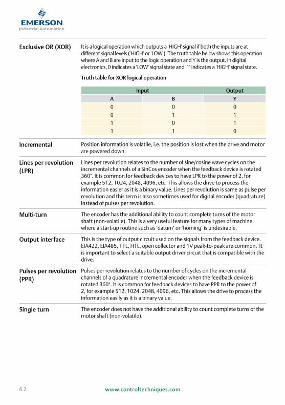
6 2 www.controltechniques.com
Exclusive OR (XOR) It is a logical operation which outputs a 'HIGH' signal if both the inputs are at different signal levels ('HIGH' or 'LOW'). The truth table below shows this operation where A and B are input to the logic operation and Y is the output. In digital electronics, 0 indicates a 'LOW' signal state and '1' indicates a 'HIGH' signal state.
Truth table for XOR logical operation
Input OutputA B Y0 0 0
0 1 1
1 0 1
1 1 0
Incremental Position information is volatile, i.e. the position is lost when the drive and motor are powered down.
Lines per revolution (LPR)
Lines per revolution relates to the number of sine/cosine wave cycles on the incremental channels of a SinCos encoder when the feedback device is rotated 360°. It is common for feedback devices to have LPR to the power of 2, for example 512, 1024, 2048, 4096, etc. This allows the drive to process the information easier as it is a binary value. Lines per revolution is same as pulse per revolution and this term is also sometimes used for digital encoder (quadrature) instead of pulses per revolution.
Multi-turn The encoder has the additional ability to count complete turns of the motor shaft (non-volatile). This is a very useful feature for many types of machine where a start-up routine such as ‘datum’ or ‘homing’ is undesirable.
Output interface This is the type of output circuit used on the signals from the feedback device. EIA422, EIA485, TTL, HTL, open collector and 1V peak-to-peak are common. It is important to select a suitable output driver circuit that is compatible with the drive.
Pulses per revolution (PPR)
Pulses per revolution relates to the number of cycles on the incremental channels of a quadrature incremental encoder when the feedback device is rotated 360°. It is common for feedback devices to have PPR to the power of 2, for example 512, 1024, 2048, 4096, etc. This allows the drive to process the information easily as it is a binary value.
Single turn The encoder does not have the additional ability to count complete turns of the motor shaft (non-volatile).

6 3www.controltechniques.com
7 Acknowledgement
The information given in above document has been understood and explained from reading material available from following listed feedback motor manufacturers. Some figures in this document have also been reproduced from datasheets provided by these manufacturers.
1. IET Handbook A5 Position and Speed Feedback 2. SICK/-Stegmann 3. Heidenhain 4. Renishaw 5. Hohner 6. Tamagawa Seiki 7. TR Electronic
8 Appendix
8.1 Encoder manufacturers - Information
8.1.1 Heidenhain
http://www.heidenhain.com
8.1.2 Stegmann/SICK
http://www.stegmann.com
8.1.3 Renishaw
http://www.renishaw.com
8.1.4 Hohner
http://www.hohner.com
8.1.5 Tamagawa Seiki
http://www.tamagawa-seiki.co.jp/english/index.html
8.1.6 TR Electronic
http://www.trelectronic.com

6 4 www.controltechniques.com
Our simple, flexible product lines make choosing the right drive and options very easy. For more demanding solutions our engineers, located within our Drive Centre and Reseller network, are available to discuss your needs and provide advice. For further details, please refer to the brochures below, which are downloadable from www.controltechniques.com.
For printed versions, please see the back cover for the contact details of your nearest supplier.
Control Techniques Company Profile
Company overview
AC & DC Drives, Servos and Drive Systems
Product Overview 100V / 200V /
400V / 575V/
690V
0.25kW to
1.9MW
Commander SK General purpose AC drive 100V / 200V /
400V / 575V/
690V
0.25kW to
132kW
Unidrive SP panel mounting
High performance AC and servo drive
200V / 400V /
575V / 690V
0.37kW to
132kW
Unidrive SP Free Standing
Fully engineered AC drives 400V / 575V /
690V
90kW to
1.6MW
Unidrive SP Modular
High power modular AC drive 200V / 400V /
575V / 690V
45kW to
1.9MW
Mentor MP High performance DC drive 400V / 575V /
690V
25A to 7400A
Digitax ST Intelligent, compact and dynamic servo drive
200V / 400V 0.72Nm to
18.8Nm
(56.4Nm Peak)
Affinity Dedicated HVAC/R drive for building automation and refrigeration
200V / 400V /
575V / 690V
0.75kW to
132kW

6 5www.controltechniques.com
Unimotor fm Performance AC brushless servo motor
0.72Nm to
136Nm
(408Nm Peak)
Unimotor hd High dynamic AC brushless servo motor for Control Techniques drives
0.72 Nm to
18.8 Nm
(56.4 Nm peak)

6 6 www.controltechniques.com

6 7www.controltechniques.com

© Control Techniques 2011. The information contained in this brochure is for guidance only and does not
form part of any contract.The accuracy cannot be guaranteed as Control Techniques have an ongoing process
of development and reserve the right to change the specification of their products without notice. P.N. 0704-0010-02
* Operated by sister company
DRIVING THE WORLD...
Control Techniques Drive & Application Centres
Control Techniques Distributors
AUSTRALIAMelbourne Application CentreT: +613 973 [email protected]
Sydney Drive CentreT: +61 2 9838 [email protected]
AUSTRIALinz Drive CentreT: +43 7229 [email protected]
BELGIUMBrussels Drive CentreT: +32 1574 [email protected]
BRAZILSão Paulo Application CentreT: +55 11 3618 [email protected]
CANADAToronto Drive CentreT: +1 905 949 [email protected]
Calgary Drive CentreT: +1 403 253 [email protected]
CHINAShanghai Drive CentreT: +86 21 5426 [email protected]
Beijing Application CentreT: +86 10 856 31122 ext [email protected]
CZECH REPUBLICBrno Drive CentreT: +420 511 [email protected]
DENMARKCopenhagen Drive CentreT: +45 4369 [email protected]
FRANCE*Angoulême Drive CentreT: +33 5 4564 [email protected]
GERMANYBonn Drive CentreT: +49 2242 [email protected]
Chemnitz Drive CentreT: +49 3722 [email protected]
Darmstadt Drive CentreT: +49 6251 [email protected]
GREECE*Athens Application CentreT: +0030 210 57 86086/[email protected]
HOLLANDRotterdam Drive CentreT: +31 184 [email protected]
HONG KONGHong Kong Application CentreT: +852 2979 [email protected]
INDIAChennai Drive CentreT: +91 44 2496 1123/ 2496 1130/2496 [email protected]
Pune Application CentreT: +91 20 2612 7956/2612 [email protected]
New Delhi Application CentreT: +91 112 2581 [email protected]
IRELANDNewbridge Drive CentreT: +353 45 [email protected]
ITALYMilan Drive CentreT: +39 02575 [email protected]
Reggio Emilia Application CentreT: +39 02575 [email protected]
Vicenza Drive CentreT: +39 0444 [email protected]
KOREASeoul Application CentreT: +82 2 3483 [email protected]
MALAYSIAKuala Lumpur Drive CentreT: +603 5634 [email protected]
REPUBLIC OF SOUTH AFRICAJohannesburg Drive CentreT: +27 11 462 [email protected]
Cape Town Application CentreT: +27 21 556 [email protected]
RUSSIAMoscow Application Centre T: +7 495 981 [email protected]
SINGAPORESingapore Drive CentreT: +65 6891 [email protected]
SLOVAKIAEMERSON A.ST: +421 32 7700 [email protected]
SPAINBarcelona Drive CentreT: +34 93 680 [email protected]
Bilbao Application CentreT: +34 94 620 [email protected]
Valencia Drive CentreT: +34 96 154 [email protected]
SWEDEN*Stockholm Application CentreT: +468 554 241 [email protected]
SWITZERLANDLausanne Application CentreT: +41 21 637 [email protected]
Zurich Drive CentreT: +41 56 201 [email protected]
TAIWANTaipei Application CentreT: +886 2 8161 [email protected]
THAILANDBangkok Drive CentreT: +66 2962 2092 [email protected]
TURKEYIstanbul Drive CentreT: +90 216 [email protected]
UAE*Emerson FZET: +971 4 [email protected]
UNITED KINGDOMTelford Drive CentreT: +44 1952 [email protected]
USACalifornia Drive CentreT: +1 562 943 [email protected]
Charlotte Application CentreT: +1 704 393 [email protected]
Chicago Application CentreT: +1 630 752 9090 [email protected]
Cleveland Drive CentreT: +1 440 717 [email protected]
Florida Drive CentreT: +1 239 693 [email protected]
Latin America Sales OfficeT: +1 305 818 [email protected]
Minneapolis US HeadquartersT: +1 952 995 [email protected]
Oregon Drive CentreT: +1 503 266 [email protected]
Providence Drive CentreT: +1 401 541 [email protected]
Utah Drive CentreT: +1 801 566 [email protected]
ARGENTINAEuro Techniques SAT: +54 11 4331 [email protected]
BAHRAINEmerson FZET: +971 4 [email protected]
BULGARIABLS - Automation LtdT: +359 32 968 [email protected]
CHILEIngeniería Y Desarrollo Tecnológico S.AT: +56 2 719 [email protected]
COLOMBIASistronic LTDAT: +57 2 555 60 [email protected]
Redes Electricas S.A.T: +57 1 364 [email protected]
CROATIAZigg-Pro d.o.o T: +385 1 3463 [email protected]
CYPRUSAcme Industrial Electronic Services LtdT: +3572 5 [email protected]
EGYPTSamiramT: +202 29703868/+202 [email protected]
EL SALVADORServielectric Industrial S.A. de C.V.T: +503 2278 [email protected]
FINLANDSKS ControlT: +358 207 [email protected]
GUATEMALAMICE, S.A.T: +502 5510 [email protected]
HONDURASTemtronics HondurasT: +504 550 [email protected]
HUNGARYControl-VH KftT: +361 431 [email protected]
ICELANDSamey ehfT: +354 510 [email protected]
INDONESIAPt Apikon IndonesiaT: +65 6468 [email protected]
Pt Yua Esa Sempurna SejahteraT: +65 6468 [email protected]
ISRAELDor Drives Systems LtdT: +972 3900 [email protected]
KENYAKassam & Bros Co. LtdT: +254 2 556 [email protected]
KUWAITEmerson FZET: +971 4 [email protected]
LATVIAEMTT: +371 760 [email protected]
LEBANONBlack Box Automation & ControlT: +961 1 [email protected]
LITHUANIAElinta UABT: +370 37 351 [email protected]
MALTAMekanika LimitedT: +35621 442 [email protected]
MEXICOMELCSA S.A. de CVT: +52 55 5561 [email protected]
MOROCCOCietecT: +212 22 [email protected]
NEW ZEALANDAdvanced Motor Control. Ph.T: +64 (0) 274 363 [email protected]
PERUIntech S.A.T: +51 1 224 [email protected]
PHILIPPINESControl Techniques Singapore LtdT: +65 6468 [email protected]
POLANDAPATOR CONTROL Sp. z o.oT: +48 56 6191 [email protected]
PORTUGALHarker Sumner S.AT: +351 22 947 [email protected]
PUERTO RICOMotion Industries Inc.T: +1 787 251 [email protected]
QATAREmerson FZET: +971 4 [email protected]
ROMANIAC.I.T. AutomatizariT: [email protected]
SAUDI ARABIAA. Abunayyan Electric Corp.T: +9661 477 [email protected]
SERBIA & MONTENEGROMaster Inzenjering d.o.o T: +381 24 551 [email protected]
SLOVENIAPS LogatecT: +386 1 750 [email protected]
TUNISIASIA Ben Djemaa & CIET: +216 1 332 [email protected]
URUGUAYSECOIN S.A. T: +5982 [email protected]
VENEZUELADigimex Sistemas C.A.T: +58 243 551 [email protected]
VIETNAMN.Duc ThinhT: +84 8 [email protected]