Firewall and IPS Deployment Guide - · PDF fileBusiness decision makers may find this section...
79
Transcript of Firewall and IPS Deployment Guide - · PDF fileBusiness decision makers may find this section...

SBA BORDERLESS NETWORKS
DEPLOYMENTGUIDE
S M A R T B U S I N E S S A R C H I T E C T U R E
August 2012 Series
Firewall and IPS Deployment Guide

PrefaceAugust 2012 Series
Preface
Who Should Read This GuideThis Cisco® Smart Business Architecture (SBA) guide is for people who fill a variety of roles:
• Systems engineers who need standard procedures for implementing solutions
• Project managers who create statements of work for Cisco SBA implementations
• Sales partners who sell new technology or who create implementation documentation
• Trainers who need material for classroom instruction or on-the-job training
In general, you can also use Cisco SBA guides to improve consistency among engineers and deployments, as well as to improve scoping and costing of deployment jobs.
Release SeriesCisco strives to update and enhance SBA guides on a regular basis. As we develop a series of SBA guides, we test them together, as a complete system. To ensure the mutual compatibility of designs in Cisco SBA guides, you should use guides that belong to the same series.
The Release Notes for a series provides a summary of additions and changes made in the series.
All Cisco SBA guides include the series name on the cover and at the bottom left of each page. We name the series for the month and year that we release them, as follows:
month year Series
For example, the series of guides that we released in August 2012 are the “August 2012 Series”.
You can find the most recent series of SBA guides at the following sites:
Customer access: http://www.cisco.com/go/sba
Partner access: http://www.cisco.com/go/sbachannel
How to Read CommandsMany Cisco SBA guides provide specific details about how to configure Cisco network devices that run Cisco IOS, Cisco NX-OS, or other operating systems that you configure at a command-line interface (CLI). This section describes the conventions used to specify commands that you must enter.
Commands to enter at a CLI appear as follows:
configure terminal
Commands that specify a value for a variable appear as follows:
ntp server 10.10.48.17
Commands with variables that you must define appear as follows:
class-map [highest class name]
Commands shown in an interactive example, such as a script or when the command prompt is included, appear as follows:
Router# enable
Long commands that line wrap are underlined. Enter them as one command:
wrr-queue random-detect max-threshold 1 100 100 100 100 100 100 100 100
Noteworthy parts of system output or device configuration files appear highlighted, as follows:
interface Vlan64 ip address 10.5.204.5 255.255.255.0
Comments and QuestionsIf you would like to comment on a guide or ask questions, please use the SBA feedback form.
If you would like to be notified when new comments are posted, an RSS feed is available from the SBA customer and partner pages.

Table of ContentsAugust 2012 Series
What’s In This SBA Guide . . . . . . . . . . . . . . . . . . . . . . . . . . . . . . . . . . . . . . . . . . . . . . . . . .1
Cisco SBA Borderless Networks . . . . . . . . . . . . . . . . . . . . . . . . . . . . . . . . . . . . . . . . 1
Route to Success . . . . . . . . . . . . . . . . . . . . . . . . . . . . . . . . . . . . . . . . . . . . . . . . . . . . . . . 1
About This Guide . . . . . . . . . . . . . . . . . . . . . . . . . . . . . . . . . . . . . . . . . . . . . . . . . . . . . . . 1
Introduction . . . . . . . . . . . . . . . . . . . . . . . . . . . . . . . . . . . . . . . . . . . . . . . . . . . . . . . . . . . . . . . .2
Related Reading . . . . . . . . . . . . . . . . . . . . . . . . . . . . . . . . . . . . . . . . . . . . . . . . . . . . . . . . 2
Design Goals . . . . . . . . . . . . . . . . . . . . . . . . . . . . . . . . . . . . . . . . . . . . . . . . . . . . . . . . . . . 3
Architecture Overview . . . . . . . . . . . . . . . . . . . . . . . . . . . . . . . . . . . . . . . . . . . . . . . . . . . . .5
Internet Edge Connectivity . . . . . . . . . . . . . . . . . . . . . . . . . . . . . . . . . . . . . . . . . . . . . . 6
Firewall . . . . . . . . . . . . . . . . . . . . . . . . . . . . . . . . . . . . . . . . . . . . . . . . . . . . . . . . . . . . . . . . . . . .8
Business Overview . . . . . . . . . . . . . . . . . . . . . . . . . . . . . . . . . . . . . . . . . . . . . . . . . . . . . . 8
Technology Overview . . . . . . . . . . . . . . . . . . . . . . . . . . . . . . . . . . . . . . . . . . . . . . . . . . . 8
Deployment Details . . . . . . . . . . . . . . . . . . . . . . . . . . . . . . . . . . . . . . . . . . . . . . . . . . . . . 9
Configuring the Firewall . . . . . . . . . . . . . . . . . . . . . . . . . . . . . . . . . . . . . . . . . . . . . . . . . 9
Configuring Firewall High Availability . . . . . . . . . . . . . . . . . . . . . . . . . . . . . . . . . . 13
Configuring Management DMZ . . . . . . . . . . . . . . . . . . . . . . . . . . . . . . . . . . . . . . . . 15
Configuring the Firewall Internet Edge . . . . . . . . . . . . . . . . . . . . . . . . . . . . . . . . . 21
Configuring the Web DMZ . . . . . . . . . . . . . . . . . . . . . . . . . . . . . . . . . . . . . . . . . . . . . 35
Firewall Summary . . . . . . . . . . . . . . . . . . . . . . . . . . . . . . . . . . . . . . . . . . . . . . . . . . . . . . 39
Intrusion Prevention . . . . . . . . . . . . . . . . . . . . . . . . . . . . . . . . . . . . . . . . . . . . . . . . . . . . . . 40
Business Overview . . . . . . . . . . . . . . . . . . . . . . . . . . . . . . . . . . . . . . . . . . . . . . . . . . . . . 40
Technology Overview . . . . . . . . . . . . . . . . . . . . . . . . . . . . . . . . . . . . . . . . . . . . . . . . . . 40
Deployment Details . . . . . . . . . . . . . . . . . . . . . . . . . . . . . . . . . . . . . . . . . . . . . . . . . . . . 42
Deploying IPS . . . . . . . . . . . . . . . . . . . . . . . . . . . . . . . . . . . . . . . . . . . . . . . . . . . . . . . . . . 43
Intrusion Prevention Summary . . . . . . . . . . . . . . . . . . . . . . . . . . . . . . . . . . . . . . . . . 53
Appendix A: Product List . . . . . . . . . . . . . . . . . . . . . . . . . . . . . . . . . . . . . . . . . . . . . . . . 54
Appendix B: Configuration Example . . . . . . . . . . . . . . . . . . . . . . . . . . . . . . . . . . . . . 56
Appendix C: Changes . . . . . . . . . . . . . . . . . . . . . . . . . . . . . . . . . . . . . . . . . . . . . . . . . . . .74
Table of Contents

About This GuideThis deployment guide contains one or more deployment chapters, which each include the following sections:
• BusinessOverview—Describes the business use case for the design. Business decision makers may find this section especially useful.
• TechnologyOverview—Describes the technical design for the business use case, including an introduction to the Cisco products that make up the design. Technical decision makers can use this section to understand how the design works.
• DeploymentDetails—Provides step-by-step instructions for deploying and configuring the design. Systems engineers can use this section to get the design up and running quickly and reliably.
You can find the most recent series of Cisco SBA guides at the following sites:
Customer access: http://www.cisco.com/go/sba
Partner access: http://www.cisco.com/go/sbachannel
What’s In This SBA Guide
Cisco SBA Borderless NetworksCisco SBA helps you design and quickly deploy a full-service business network. A Cisco SBA deployment is prescriptive, out-of-the-box, scalable, and flexible.
Cisco SBA incorporates LAN, WAN, wireless, security, data center, application optimization, and unified communication technologies—tested together as a complete system. This component-level approach simplifies system integration of multiple technologies, allowing you to select solutions that solve your organization’s problems—without worrying about the technical complexity.
Cisco SBA Borderless Networks is a comprehensive network design targeted at organizations with up to 10,000 connected users. The SBA Borderless Network architecture incorporates wired and wireless local area network (LAN) access, wide-area network (WAN) connectivity, WAN application optimization, and Internet edge security infrastructure.
Route to SuccessTo ensure your success when implementing the designs in this guide, you should first read any guides that this guide depends upon—shown to the left of this guide on the route below. As you read this guide, specific prerequisites are cited where they are applicable.
1What’s In This SBA GuideAugust 2012 Series
Internet Edge Design Overview Firewall and IPS Deployment Guide Additional Deployment Guides
BORDERLESS NETWORKS
You Are Here Dependent GuidesPrerequisite Guides

22IntroductionAugust 2012 Series
Introduction
Cisco SBA Borderless Networks is a solid network foundation designed to provide networks with up to 10,000 connected users the flexibility to sup-port new users and network services without re-engineering the network. We created a prescriptive, out-of-the-box deployment guide that is based on best-practice design principles and that delivers flexibility and scalability.
The Firewall and IPS Deployment Guide focuses on the Internet edge fire-wall and intrusion prevention system (IPS) security services that protect your organization’s gateway to the Internet. Internet service-provider connectivity and routing options provide resiliency to the design. This guide covers the creation and use of DMZ segments for use with Internet-facing services like a web presence. The IPS guidance covers Internet edge inline deployments as well as internal distribution layer IDS (promiscuous) deployments.
Related ReadingThe Internet Edge Design Overview orients you to the overall Cisco SBA design and explains the requirements that were considered when selecting specific products.
The Remote Access VPN Deployment Guide focuses on provisioning the network to provide remote access (RA) services. The deployment includes VPN access as part of the Internet edge firewalls as well as the ability to deploy RA VPN services on separate dedicated devices.
The Web Security Using WSA Deployment Guide covers deploying the Cisco Web Security Appliance for clients accessing the Internet. This covers protection from malware and viruses as well as acceptable use controls for what sites are appropriate to be visited.
The Email Security Using ESA Deployment Guide covers deployment of the Email Security Appliance in order to provide protection for the organization’s email system. Inspection of inbound emails for spam and malicious content is the focus of the deployment. It also covers adding an email demilitarized zone (DMZ) to the Internet Firewall to increase the overall security.

3IntroductionAugust 2012 Series 3
Design Goals This architecture is based on requirements gathered from customers, partners, and Cisco field personnel for organizations with up to 10,000 connected users. When designing the architecture, we considered the gathered requirements and the following design goals.
Figure 1 - Borderless Networks overview
AccessSwitches
WAAS
DistributionSwitches
AccessSwitches
WANRouters
WANRouters
Web Security
Appliance
RA-VPN Firewall
DMZServers
WAAS
Remote Site WirelessLAN Controllers
VPN
VoiceRouters
Wireless LANController
AccessSwitchStack
WANRouters
Hardware andSoftware VPN
WANRouter
Wireless LANControllers
Cisco ACE
WAASCentral Manager
Nexus2000
Nexus 5500
CommunicationsManagers
InternetRouters
Email SecurityAppliance
DMZSwitch
GuestWireless LANController
CoreSwitches
DistributionSwitches
UserAccessLayers
Data CenterFirewalls
Storage
UCS Rack-mountServers UCS Rack-mount
Server
UCS BladeChassis
Data Center
Internet Edge
WANAggregation
MPLSWANs
Teleworker /Mobile Worker
Remote Site
Regional Site
21
89
V
AccessSwitch
Remote Site
V
V
V
wwWwwW
PSTN
Headquarters
PSTNV
V
WAAS
Internet

4IntroductionAugust 2012 Series 4
Ease of Deployment, Flexibility, and Scalability
Organizations with up 10,000 users are often spread out among different geographical locations, making flexibility and scalability a critical require-ment of the network. This design uses several methods to create and maintain a scalable network:
• By keeping a small number of standard designs for common portions of the network, support staff is able to design services for, implement, and support the network more effectively.
• Our modular design approach enhances scalability. Beginning with a set of standard, global building blocks, we can assemble a scalable network to meet requirements.
• Many of the plug-in modules look identical for several service areas; this common look provides consistency and scalability in that the same support methods can be used to maintain multiple areas of the network. These modules follow standard core-distribution-access network design models and use layer separation to ensure that interfaces between the plug-ins are well defined.
Resiliency and Security
One of the keys to maintaining a highly available network is building the appropriate resilience into the network links and platforms in order to guard against single points of failure in the network. The resilience in the SBA Internet edge architecture is carefully balanced with the complexity inherent in redundant systems.
With the addition of a significant amount of delay-sensitive and drop-sensitive traffic such as voice and video conferencing, we also place a strong emphasis on recovery times. Choosing designs that reduce the time between failure detection and recovery is important for ensuring that the network stays available even in the face of a link or component failure.
Network security is also a strong component of the architecture. In a large network, there are many entry points, and we ensure that they are as secure as possible without making the network too difficult to use. Securing the network not only helps keep the network safe from attacks but is also a key component to network-wide resiliency.
Ease of Management
While this guide focuses on the deployment of the network foundation, the design takes next-phase management and operation into consideration. The configurations in the deployment guides are designed to allow the devices to be managed via normal device-management connections, such as Secure Shell (SSH) Protocol and HTTPS, as well as via Network Management System (NMS). The configuration of the NMS is not covered in this guide.
Advanced Technology–Ready
Flexibility, scalability, resiliency, and security all are characteristics of an advanced technology-ready network. The modular design of the architec-ture means that technologies can be added when the organization is ready to deploy them. However, the deployment of advanced technologies, such as collaboration, is eased because the architecture includes products and configurations that are ready to support collaboration from day one. For example:
• Access switches provide Power over Ethernet (PoE) for phone deploy-ments without the need for a local power outlet.
• The entire network is preconfigured with quality of service (QoS) to support high-quality voice.
• Multicast is configured in the network to support efficient voice and broadcast-video delivery.
• The wireless network is preconfigured for devices that send voice over the wireless LAN, providing IP telephony over 802.11 Wi-Fi (referred to as mobility) at all locations.
The Internet edge is ready to provide soft phones via VPN, as well as tradi-tional hard or desk phones, as configured in a teleworker deployment.
5Architecture OverviewAugust 2012 Series 5
Architecture Overview
The Firewall and IPS Deployment Guide is a component of the larger Internet edge design, which uses a modular design model to break the Internet edge into functional blocks by service. By modularizing the design, an organization can deploy the services as required.
The Internet edge design includes the following functional blocks:
• Firewall—Controls access into and out of the different segments of the Internet edge and provides a suite of other services, such as Network Address Translation (NAT) and DMZ creation.
• IntrusionPrevention—Inspects traffic traversing the Internet edge, looking for malicious behaviors.
• RemoteAccessVPN—Provides secure, consistent access to resources, regardless of where the user is when connecting.
• EmailSecurity—Provides spam and malware filtering service to man-age the risk associated with email.
• WebSecurity—Provides acceptable-use control and monitoring while managing the increasing risk associated with clients browsing the Internet.
Figure 2 - Internet edge in the Borderless Networks design
WANRouters
Web Security
Appliance
RA-VPN Firewall
DMZServers
WAAS
Remote Site WirelessLAN Controllers
VPN
InternetRouters
Email SecurityAppliance
DMZSwitch
GuestWireless LANController
Internet Edge
WANAggregation
30
11
wwWwwW
Internet
To Core
The primary differences in module design options are scale, performance, and resilience. To accommodate these requirements, each module of the Internet edge design is independent of the others, so you can mix and match the different design components to best meet your business requirements.
6Architecture OverviewAugust 2012 Series 6
Internet Edge ConnectivityBusiness demand for Internet connectivity has increased steadily over the last few decades; for many organizations, access to Internet-based services is a fundamental requirement for conducting day-to-day activity. Email, web access, remote-access VPN, and, more recently, cloud-based services are critical functions enabling businesses to pursue their missions. An Internet connection that supports these services must be designed to enable the organization to accomplish its Internet-based business goals.
Three factors define the business requirements for an organization’s Internet connection:
• Value of Internet-based business activity:
◦ revenue realized from Internet business
◦ savings realized by Internet-based services
• Revenue impact from loss of Internet connectivity
• Capital and operational expense of implementing and maintaining vari-ous Internet connectivity options
The organization must identify and understand its Internet connection requirements in order to effectively meet the demands of Internet-based business activity.
Internet connection speed, availability, and address space requirements are criteria that will shape an Internet connection design. The Internet con-nection must be able to accommodate an organization’s requirements for data volume to the Internet, offer sufficient resiliency to meet service-level agreements, and provide sufficient IP address space to accommodate both Internet-facing and Internet-based services.
An organization’s IT staff needs to address three main requirements when designing and implementing an Internet edge architecture:
• Connectivityspeed—What is the expected throughput required? Are short bursts of high-volume traffic expected?
• IPaddressspace—A small organization or one that does not rely heav-ily on web-based services to the Internet will have a different IP space requirement than a large organization that depends heavily on email, remote-access VPN, and content or cloud-based services offered to the Internet.
• Availability—Connection speed is only part of the equation; if con-nectivity must be maintained when the primary Internet connection fails, then the design must offer a resilient Internet connection via a second-ary Internet connection.
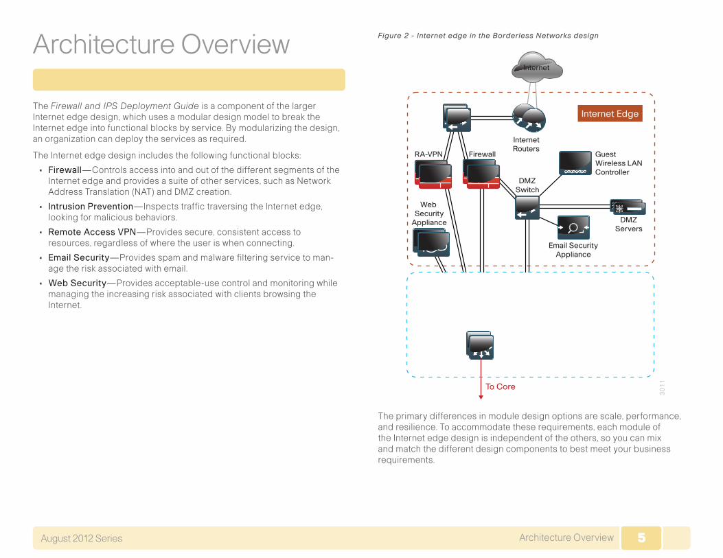
Internet connectivity options vary widely by geographic region and service provider. An organization may be able to choose between cable, DSL, leased line, or Ethernet for the physical connection to the Internet. A com-mon denominator of Internet connectivity is the Ethernet connection to the customer-premises equipment (CPE) device (cable modem, T1 CPE router, etc.), and this is assumed as the demarcation for this design.
Figure 3 - Internet connectivity demarcation for this design
30
01
Internet
Firewall
OutsideSwitches
InternetCPE Device
Organizations deploying this design typically fall into the following Internet connection speed ranges.
Table 1 - Internet connection speed requirements
Number of connected users Internet connection speed
Up to 4,500 20–50 Mbps
3,000 to 7,000 35–75 Mbps
6,000 to 10,000 70–130 Mbps
If the business needs include WAN connectivity to connect geographically diverse sites, a cost savings can be realized by combining WAN and Internet connectivity over the same service. A service provider may offer hardware to terminate WAN/Internet connectivity on premise and manage the Internet/WAN connection device. Provider-supplied hardware and service offerings may reduce operational burden. The organization must assess the impact of configuration-change lead times and configuration flexibility.
Regardless of how access is delivered, design and configuration discus-sions for this guide begin at the Ethernet handoff on the outside switch in the Internet edge.
7Architecture OverviewAugust 2012 Series 7
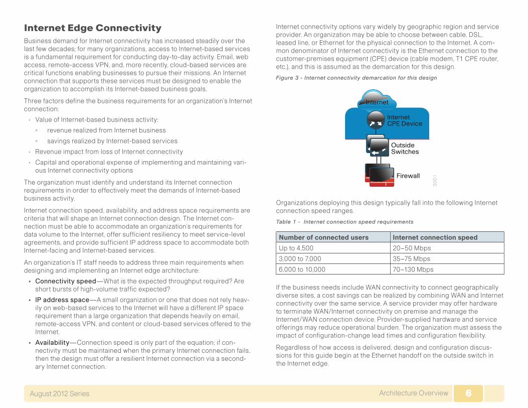
High Availability Overview
The decision to use a single or dual Internet connection should be made on your organization’s connection availability requirements. If a loss of Internet access will cause a business interruption that has a greater cost impact than the cost of a backup Internet connection, then the Dual ISP design should be used. A backup Internet connection assures continued Internet access in the event of a failure to the primary Internet connection, although some services may experience a temporary outage during the switch to the backup link. Most outbound services should be available in a few seconds. The Dual ISP design provides the following:
• Resilient outbound Internet access and inbound email services.
• Additional inbound services that can be provisioned to recover in the event of a failure, although some services may experience longer outages.
• Inbound web service that does not have seamless failover protection and requires user interaction to point the Domain Name System (DNS) records at the alternate IP address on the secondary ISP. To achieve higher web-service availability, an organization can host its web service at a colocation facility or use a fully redundant Border Gateway Protocol (BGP) design that advertises the same IP address out to different ISPs. Organizations with services that require a very high level of Internet availability should consider hosting these services at a provider’s Internet colocation facility.
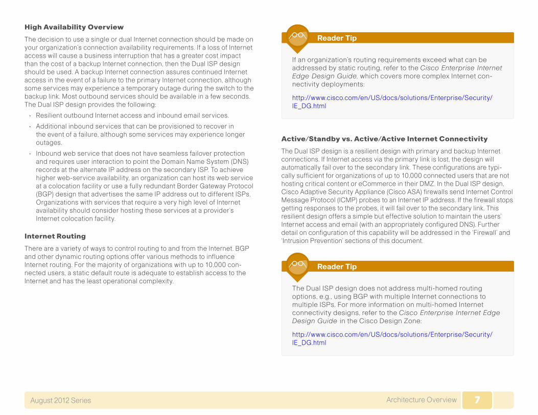
Internet Routing
There are a variety of ways to control routing to and from the Internet. BGP and other dynamic routing options offer various methods to influence Internet routing. For the majority of organizations with up to 10,000 con-nected users, a static default route is adequate to establish access to the Internet and has the least operational complexity.
If an organization’s routing requirements exceed what can be addressed by static routing, refer to the Cisco Enterprise Internet Edge Design Guide, which covers more complex Internet con-nectivity deployments:
http://www.cisco.com/en/US/docs/solutions/Enterprise/Security/IE_DG.html
Reader Tip
Active/Standby vs. Active/Active Internet Connectivity
The Dual ISP design is a resilient design with primary and backup Internet connections. If Internet access via the primary link is lost, the design will automatically fail over to the secondary link. These configurations are typi-cally sufficient for organizations of up to 10,000 connected users that are not hosting critical content or eCommerce in their DMZ. In the Dual ISP design, Cisco Adaptive Security Appliance (Cisco ASA) firewalls send Internet Control Message Protocol (ICMP) probes to an Internet IP address. If the firewall stops getting responses to the probes, it will fail over to the secondary link. This resilient design offers a simple but effective solution to maintain the users’ Internet access and email (with an appropriately configured DNS). Further detail on configuration of this capability will be addressed in the ‘Firewall’ and ‘Intrusion Prevention’ sections of this document.
The Dual ISP design does not address multi-homed routing options, e.g., using BGP with multiple Internet connections to multiple ISPs. For more information on multi-homed Internet connectivity designs, refer to the Cisco Enterprise Internet Edge Design Guide in the Cisco Design Zone:
http://www.cisco.com/en/US/docs/solutions/Enterprise/Security/IE_DG.html
Reader Tip

8FirewallAugust 2012 Series 8
Firewall
Business OverviewThe Internet edge is the point where the organization’s network connects to the Internet. This is the perimeter of the network, where a line is drawn between the public Internet and the private resources contained with an organization’s network. Worm, virus, and botnet infiltrations pose substantial threats to network performance, availability, and data security. To add to these problems, an organizations’ Internet connection can contribute to employee productivity loss and leakage of confidential data.
Internet-based attackers are a threat to an organization’s network infra-structures and data resources. Most networks connected to the Internet are subject to a constant barrage of worms, viruses, and targeted attacks. Organizations must vigilantly protect their network, user data, and customer information. Additionally, most network addresses must be translated to an Internet-routable address, and the firewall is the logical place for this function.
Network security, as applied at the firewall, must assure that the organiza-tion’s data resources are protected from snooping and tampering, and it must prevent compromise of hosts by resource-consuming worms, viruses, and botnets. Additionally, the firewall policy must establish the appropri-ate balance in order to provide security without interfering with access to Internet-based applications or hindering connectivity to business partners’ data via extranet VPN connections.
Firewall security is an integral part of every Internet edge deployment, as it protects information while meeting the need for secure, reliable networks and enforces policy in order to maintain employee productivity. Where industry regulations apply, firewalls play a crucial role in an organization’s ability to address regulatory compliance requirements. Regulatory require-ments vary by country and industry; this document does not cover specific regulatory compliance requirements.
Technology OverviewThe Cisco ASA firewall family sits between the organization’s internal network and the Internet and is a fundamental infrastructural component that minimizes the impact of network intrusions while maintaining worker productivity and data security.
This design uses Cisco ASA 5500-X Series for Internet edge firewall security. They are configured in an active/standby pair for high availability in order to ensure that Internet access is minimally impacted by firewall software maintenance or hardware failure. The Cisco ASAs are configured in routing mode. They apply Network Address Translation (NAT) and firewall policy, and they host intrusion prevention system modules to detect and mitigate malicious or harmful traffic.
Two deployment options are discussed to address Internet access require-ments for high availability and to meet operational requirements for device-level separation between remote-access VPN and firewall.
One firewall design uses a single Internet connection and integrates the remote-access VPN function in the same Cisco ASA pair that provides the firewall functionality.
Figure 4 - Single ISP topology
30
02
OutsideSwitches
DMZSwitches
InternetServers
Distribution
Cisco ASA 5525-Xwith IPS
InternalNetwork
Internet
Router

9FirewallAugust 2012 Series 9
The larger firewall design uses dual Internet connections for resilient access to the Internet. A separate pair of appliances provides remote-access VPN, allowing additional scalability and operational flexibility.
Figure 5 - Dual ISP topology
30
03
Internet
ISP A ISP B
Routers
Internet
ISP A ISP B
Routers
OutsideSwitches
DMZSwitches
InternetServers
Distribution
Cisco ASA 5525-Xwith IPS
InternalNetwork
A good portion of the configuration described in this section is common to both the single and dual ISP designs. If a section describes configuration that is only used in one of the designs, this is mentioned in that section.
The configurations are for any of the one-rack-unit Cisco ASA security appliances.
Hardware applied in this design is selected based on the following perfor-mance values. It is important to note that Internet connection speed is not the only data point when considering Cisco ASA device performance. To choose the correct platform, you must consider traffic that traverses the firewall from the internal network to the DMZ as well as inter-DMZ traffic.
Table 2 - Cisco ASA family device performance
Cisco ASA family product Real-World Firewall Throughput (EMIX)
Cisco ASA 5512-X 500 Mbps
Cisco ASA 5515-X 600 Mbps
Cisco ASA 5525-X 1 Gbps
Cisco ASA 5545-X 1.5 Gbps
Deployment Details
Configuring the Firewall
1. Configure the LAN distribution switch
2. Apply Cisco ASA initial configuration
3. Configure internal routing
4. Configure user authentication
5. Configure NTP and logging
6. Configure device-management protocols
Process
The Cisco ASA can be configured from the command line or from the graphical user interface, Cisco Adaptive Security Device Manager (ASDM). Cisco ASDM is the primary method of configuration illustrated in this deployment guide. This process uses the command line to initially configure the appliance and then uses Cisco ASDM to manage the configuration.
Only the primary Cisco ASA in the high availability pair needs to be configured. The Configuring Firewall High Availability process will set up high availability and synchronize the configuration from the primary to the secondary device.
Procedure 1 Configure the LAN distribution switch
The LAN distribution switch is the path to the organization’s internal network. A unique VLAN supports the Internet edge devices, and the routing protocol peers with the appliances across this network. To support future use, the connections from the ASAs to the inside LAN distribution switches are configured as trunks.

10FirewallAugust 2012 Series 10
This procedure assumes that the distribution switch has already been configured following the guidance in the Cisco SBA—Borderless Networks LAN Deployment Guide. Only the proce-dures required to support the integration of the firewall into the deployment are included in this guide.
Reader Tip
Step 1: Configure the Internet edge VLAN on the LAN distribution switch.
vlan 300 name InternetEdge!
Step 2: Configure Layer 3.
Configure a switched virtual interface (SVI) so devices in the VLAN can communicate with the rest of the network.
interface vlan 300 description Internet Edge SVI ip address 10.4.24.1 255.255.255.224 no shutdown
Step 3: Configure the interfaces that are connected to the Internet edge firewall.
An 802.1Q trunk is used for the connection to the Internet edge firewall, which allows the distribution switch to provide the Layer 3 services to all the VLANs defined on the firewall. The VLANs allowed on the trunk are pruned to only the VLANs that are active on the firewall.
interface GigabitEthernet1/0/24 description IE-ASA5545a Gig0/0!interface GigabitEthernet2/0/24 description IE-ASA5545b Gig0/0!interface range GigabitEthernet1/0/24, GigabitEthernet2/0/24switchportswitchport trunk encapsulation dot1q
switchport trunk allowed vlan 300 switchport mode trunk spanning-tree portfast trunk macro apply EgressQoSlogging event link-status logging event trunk-status no shutdown
The Cisco Catalyst 6500 uses the command spanning-treeportfastedgetrunk to enable portfast on a trunk port. The Catalyst 4500 does not require the switchporttrunkencapsulationdot1q command.
Step 4: Summarize the Internet edge network range towards the core.
Summarization of routes only applies to networks that use separate distribu-tion and core layers. If your network has a collapsed core and distribution, proceed to the next step.
interface range TenGigabitEthernet1/1/1, TenGigabitEthernet2/1/1 ip summary-address eigrp 100 10.4.24.0 255.255.248.0
Step 5: Configure the routing protocol to form neighbor relationships on the Internet edge VLAN.
router eigrp 100 no passive-interface Vlan300
Procedure 2 Apply Cisco ASA initial configuration
This procedure configures connectivity to the appliance from the internal network in order to enable management access.
Step 1: Configure the appliance host name.
hostname IE-ASA5545
Step 2: Configure the appliance interface that is connected to the internal LAN distribution switch as a subinterface on VLAN 300. The interface is configured as a VLAN trunk port in order to allow flexibility to add additional connectivity.
interface GigabitEthernet0/0no shutdown

11FirewallAugust 2012 Series 11
!interface GigabitEthernet0/0.300 vlan 300 nameif inside ip address 10.4.24.30 255.255.255.224
Step 3: Enable the dedicated management interface and remove any IP address that might be applied. This interface will only be used for IPS management.
interface Management0/0 nameif IPS-mgmt no ip address no shutdown
Step 4: Configure an administrative username and password.
username admin password [password] privilege 15
All passwords in this document are examples and should not be used in production configurations. Follow your organization’s policy, or if no policy exists, create a password using a minimum of 8 characters with a combination of uppercase, lowercase, and numbers.
Tech Tip
Procedure 3 Configure internal routing
A dynamic routing protocol is used to easily configure reachability between networks connected to the appliance and those that are internal to the organization.
Step 1: Enable Enhanced Interior Gateway Routing Protocol (EIGRP) on the appliance.
router eigrp 100
Step 2: Configure the appliance to advertise its statically defined routes and connected networks that are inside the Internet edge network range.
no auto-summary network 10.4.24.0 255.255.252.0 redistribute static
Step 3: Configure EIGRP to peer with neighbors across the inside interface only.
passive-interface default no passive-interface inside
Step 4: Configure a network object for the summary address of the inter-nal network. The network object will be used later during security policy configuration.
object network internal-network subnet 10.4.0.0 255.254.0.0 description The organization’s internal network range
Procedure 4 Configure user authentication
(Optional)
As networks scale in the number of devices to maintain, it poses an opera-tional burden to maintain local user accounts on every device. A centralized authentication, authorization, and accounting (AAA) service reduces opera-tional tasks per device and provides an audit log of user access, for security compliance and root cause analysis. When AAA is enabled for access control, all management access to the network infrastructure devices (SSH and HTTPS) is controlled by AAA.

12FirewallAugust 2012 Series 12
The AAA server used in this architecture is the Cisco Secure Authentication Control Server (ACS). Configuration of Cisco Secure ACS is discussed in the Cisco SBA—Borderless Networks LAN and Wireless LAN 802.1x Authentication Deployment Guide.
Reader Tip
TACACS+ is the primary protocol used to authenticate management logins on the infrastructure devices to the AAA server. A local AAA user database was defined already to provide a fallback authentication source in case the centralized TACACS+ server is unavailable.
Step 1: Configure the TACACS+ server.
aaa-server AAA-SERVER protocol tacacs+aaa-server AAA-SERVER (inside) host 10.4.48.15 SecretKey
Step 2: Configure the appliance’s management authentication to use the TACACS+ server first and then the local user database if the TACACS+ server is unavailable.
aaa authentication enable console AAA-SERVER LOCALaaa authentication ssh console AAA-SERVER LOCALaaa authentication http console AAA-SERVER LOCALaaa authentication serial console AAA-SERVER LOCAL
Step 3: Configure the appliance to use AAA to authorize management users.
aaa authorization exec authentication-server
User authorization on the Cisco ASA firewall does not automati-cally present the user with the enable prompt if they have a privilege level of 15, unlike Cisco IOS devices.
Tech Tip
Procedure 5 Configure NTP and logging
Logging and monitoring are critical aspects of network security devices in order to support troubleshooting and policy-compliance auditing.
The Network Time Protocol (NTP) is designed to synchronize time across a network of devices. An NTP network usually gets its time from an authorita-tive time source, such as a radio clock or an atomic clock attached to a time server. NTP then distributes this time across the organization’s network.
Network devices should be programmed to synchronize to a local NTP server in the network. The local NTP server typically references a more accurate clock feed from an outside source.
There is a range of detail that can be logged on the appliance. Informational-level logging provides the ideal balance between detail and log-message volume. Lower log levels produce fewer messages, but they do not produce enough detail to effectively audit network activity. Higher log levels produce a larger volume of messages but do not add sufficient value to justify the number of messages logged.
Step 1: Configure the NTP server.
ntp server 10.4.48.17
Step 2: Configure the time zone.
clock timezone PST -8clock summer-time PDT recurring
Step 3: Configure which logs to store on the appliance.
logging enablelogging buffered informational
Procedure 6 Configure device-management protocols
Cisco ASDM requires that the appliance’s HTTPS server be available. Be sure that the configuration includes networks where administrative staff has access to the device through Cisco ASDM; the appliance can offer controlled Cisco ASDM access for a single address or management subnet (in this case, 10.4.48.0/24).

13FirewallAugust 2012 Series 13
HTTPS and Secure Shell (SSH) are more secure replacements for the HTTP and Telnet protocols. They use Secure Sockets Layer (SSL) and Transport Layer Security (TLS) to provide device authentication and data encryption.
Use SSH and HTTPS protocols in order to more securely manage the device. Both protocols are encrypted for privacy, and the non-secure protocols, Telnet and HTTP, are turned off.
Simple Network Management Protocol (SNMP) is enabled to allow the network infrastructure devices to be managed by a Network Management System (NMS). SNMPv2c is configured for a read-only community string.
Step 1: Allow internal administrators to remotely manage the appliance over HTTPS and SSH.
domain-name cisco.local http server enable http 10.4.48.0 255.255.255.0 inside ssh 10.4.48.0 255.255.255.0 inside ssh version 2
Step 2: Configure the appliance to allow SNMP polling from the NMS.
snmp-server host inside 10.4.48.35 community ciscosnmp-server community cisco
Configuring Firewall High Availability
1. Configure resilience on the primary firewall
2. Configuring standby firewall for resilience
Process
The Cisco ASA appliances are set up as a highly available active/standby pair. Active/standby is used, rather than an active/active configuration, because this allows the same appliance to be used for firewall and VPN services (VPN functionality is disabled on the appliance in active/active configuration). In the event that the active ASA appliance fails or needs to be taken out of service for maintenance, the secondary ASA appliance
assumes all active firewall, IPS, and VPN functions. In an active/standby configuration, only one device is passing traffic at a time; thus, the Cisco ASAs must be sized so that the entire traffic load can be handled by either device in the pair.
Both units in the failover pair must be the same model, with identical feature licenses and IPS (if the software module is installed). For failover to be enabled, the secondary Cisco ASA unit needs to be powered up and cabled to the same networks as the primary unit.
One interface on each Cisco ASA is configured as the state-synchronization interface, which the appliances use to share configuration updates, deter-mine which device in the high availability pair is active, and exchange state information for active connections. The failover interface carries the state synchronization information. All session state is replicated from the primary to the standby unit though this interface. There can be a substantial amount of data, and it is recommended that this be a dedicated interface.
By default, the appliance can take from 2 to 25 seconds to recover from a failure. Tuning the failover poll times can reduce that to 0.5 to 5 seconds. On an appropriately sized ASA, the poll times can be tuned down without performance impact to the appliance, which minimizes the downtime a user experiences during failover. Reducing the failover timer intervals below the values in this guide is not recommended.
Procedure 1 Configure resilience on primary firewall
This procedure describes how to configure active/standby failover. The failover key value must match on both devices in an active/standby pair. This key is used for two purposes: to authenticate the two devices to each other, and to secure state synchronization messages between the devices, which enables the Cisco ASA pair to maintain service for existing connections in the event of a failover.
Step 1: On the primary Cisco ASA, enable failover.
failover
Step 2: Configure the Cisco ASA as the primary appliance of the high availability pair.
failover lan unit primary

14FirewallAugust 2012 Series 14
Step 3: Configure the failover interface.
failover lan interface failover GigabitEthernet0/2failover key FailoverKeyfailover replication httpfailover link failover GigabitEthernet0/2
Step 4: To minimize the downtime experienced during failover, tune the failover poll timers.
failover polltime unit msec 200 holdtime msec 800 failover polltime interface msec 500 holdtime 5
Step 5: Configure the failover interface IP address.
failover interface ip failover 10.4.24.33 255.255.255.248 standby 10.4.24.34
Step 6: Enable the failover interface.
interface GigabitEthernet0/2 no shutdown
Step 7: Configure the standby IP address and monitoring of the inside interface.
interface GigabitEthernet0/0.300 ip address 10.4.24.30 255.255.255.224 standby 10.4.24.29monitor-interface inside
Procedure 2 Configuring standby firewall for resilience
Step 1: On the secondary Cisco ASA, enable failover.
failover
Step 2: Configure the Cisco ASA as the secondary appliance of the high availability pair.
failover lan unit secondary
Step 3: Configure the failover interface.
failover lan interface failover GigabitEthernet0/2failover key FailoverKeyfailover replication httpfailover link failover GigabitEthernet0/2
Step 4: To minimize the downtime experienced during failover, tune the failover poll timers.
failover polltime unit msec 200 holdtime msec 800 failover polltime interface msec 500 holdtime 5
Step 5: Configure the failover interface IP address.
failover interface ip failover 10.4.24.33 255.255.255.248 standby 10.4.24.34
Step 6: Enable the failover interface.
interface GigabitEthernet0/2 no shutdown
Step 7: To verify standby synchronization between the Cisco ASA devices, on the command-line interface of the primary appliance, issue the showfailoverstatecommand.
IE-ASA5545# show failover state
State Last Failure Reason Date/TimeThis host - Primary Active NoneOther host - Secondary Standby Ready None
====Configuration State=== Sync Done====Communication State=== Mac set
15FirewallAugust 2012 Series 15
Configuring Management DMZ
1. Configure the DMZ switch
2. Configure the demilitarized zone interface
3. Configure the DMZ routing
4. Configure the DMZ security policy
Process
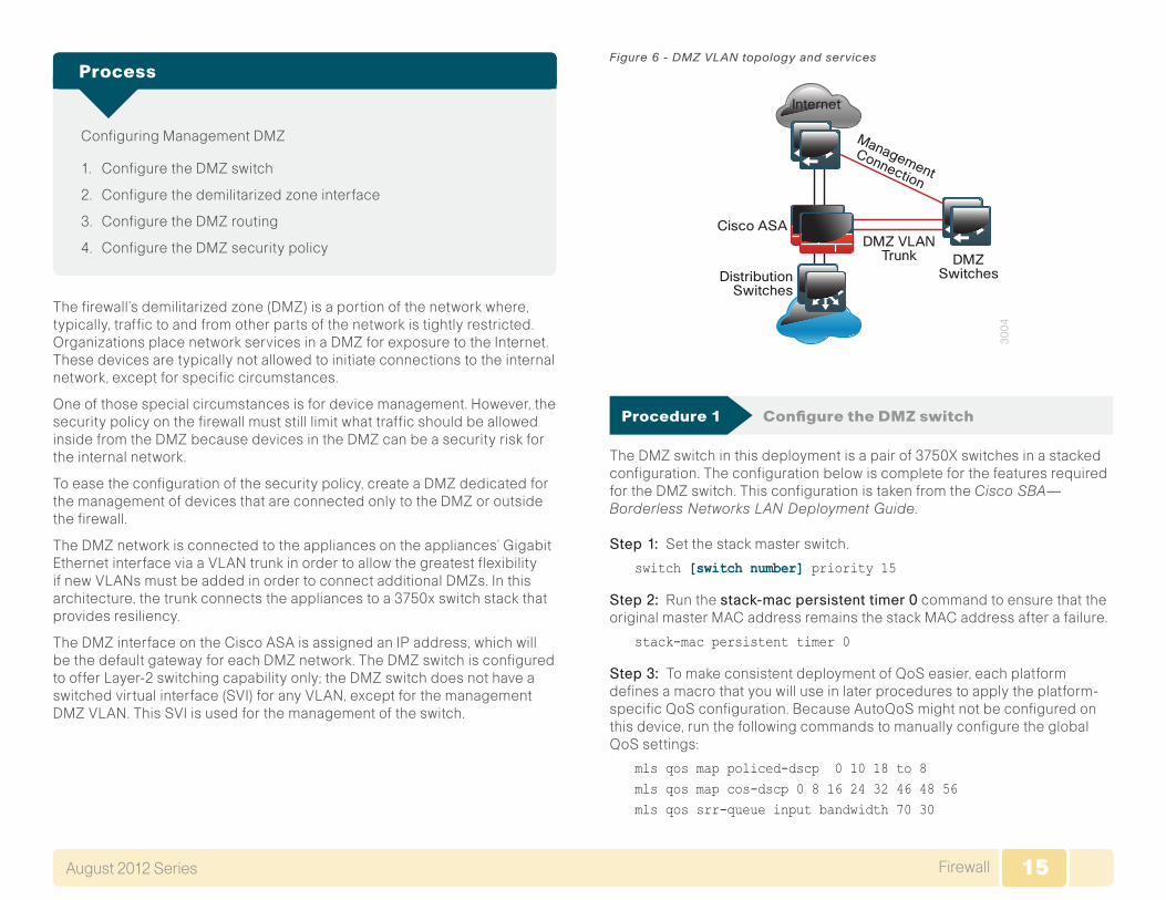
The firewall’s demilitarized zone (DMZ) is a portion of the network where, typically, traffic to and from other parts of the network is tightly restricted. Organizations place network services in a DMZ for exposure to the Internet. These devices are typically not allowed to initiate connections to the internal network, except for specific circumstances.
One of those special circumstances is for device management. However, the security policy on the firewall must still limit what traffic should be allowed inside from the DMZ because devices in the DMZ can be a security risk for the internal network.
To ease the configuration of the security policy, create a DMZ dedicated for the management of devices that are connected only to the DMZ or outside the firewall.
The DMZ network is connected to the appliances on the appliances’ Gigabit Ethernet interface via a VLAN trunk in order to allow the greatest flexibility if new VLANs must be added in order to connect additional DMZs. In this architecture, the trunk connects the appliances to a 3750x switch stack that provides resiliency.
The DMZ interface on the Cisco ASA is assigned an IP address, which will be the default gateway for each DMZ network. The DMZ switch is configured to offer Layer-2 switching capability only; the DMZ switch does not have a switched virtual interface (SVI) for any VLAN, except for the management DMZ VLAN. This SVI is used for the management of the switch.
Figure 6 - DMZ VLAN topology and services
30
04
ManagementConnection
DMZ VLANTrunk DMZ
SwitchesDistributionSwitches
Cisco ASA
Internet
Procedure 1 Configure the DMZ switch
The DMZ switch in this deployment is a pair of 3750X switches in a stacked configuration. The configuration below is complete for the features required for the DMZ switch. This configuration is taken from the Cisco SBA—Borderless Networks LAN Deployment Guide.
Step 1: Set the stack master switch.
switch [switch number] priority 15
Step 2: Run the stack-macpersistenttimer0 command to ensure that the original master MAC address remains the stack MAC address after a failure.
stack-mac persistent timer 0
Step 3: To make consistent deployment of QoS easier, each platform defines a macro that you will use in later procedures to apply the platform-specific QoS configuration. Because AutoQoS might not be configured on this device, run the following commands to manually configure the global QoS settings:
mls qos map policed-dscp 0 10 18 to 8mls qos map cos-dscp 0 8 16 24 32 46 48 56mls qos srr-queue input bandwidth 70 30

16FirewallAugust 2012 Series 16
mls qos srr-queue input threshold 1 80 90mls qos srr-queue input priority-queue 2 bandwidth 30mls qos srr-queue input cos-map queue 1 threshold 2 3mls qos srr-queue input cos-map queue 1 threshold 3 6 7mls qos srr-queue input cos-map queue 2 threshold 1 4mls qos srr-queue input dscp-map queue 1 threshold 2 24mls qos srr-queue input dscp-map queue 1 threshold 3 48 49 50 51 52 53 54 55mls qos srr-queue input dscp-map queue 1 threshold 3 56 57 58 59 60 61 62 63mls qos srr-queue input dscp-map queue 2 threshold 3 32 33 40 41 42 43 44 45mls qos srr-queue input dscp-map queue 2 threshold 3 46 47mls qos srr-queue output cos-map queue 1 threshold 3 4 5mls qos srr-queue output cos-map queue 2 threshold 1 2mls qos srr-queue output cos-map queue 2 threshold 2 3mls qos srr-queue output cos-map queue 2 threshold 3 6 7mls qos srr-queue output cos-map queue 3 threshold 3 0mls qos srr-queue output cos-map queue 4 threshold 3 1mls qos srr-queue output dscp-map queue 1 threshold 3 32 33 40 41 42 43 44 45mls qos srr-queue output dscp-map queue 1 threshold 3 46 47mls qos srr-queue output dscp-map queue 2 threshold 1 16 17 18 19 20 21 22 23mls qos srr-queue output dscp-map queue 2 threshold 1 26 27 28 29 30 31 34 35mls qos srr-queue output dscp-map queue 2 threshold 1 36 37 38 39mls qos srr-queue output dscp-map queue 2 threshold 2 24mls qos srr-queue output dscp-map queue 2 threshold 3 48 49 50 51 52 53 54 55mls qos srr-queue output dscp-map queue 2 threshold 3 56 57 58 59 60 61 62 63mls qos srr-queue output dscp-map queue 3 threshold 3 0 1 2 3 4 5 6 7mls qos srr-queue output dscp-map queue 4 threshold 1 8 9 11 13 15
mls qos srr-queue output dscp-map queue 4 threshold 2 10 12 14mls qos queue-set output 1 threshold 1 100 100 50 200mls qos queue-set output 1 threshold 2 125 125 100 400mls qos queue-set output 1 threshold 3 100 100 100 3200mls qos queue-set output 1 threshold 4 60 150 50 200mls qos queue-set output 1 buffers 15 25 40 20mls qos!macro name EgressQoS mls qos trust dscp queue-set 1 srr-queue bandwidth share 1 30 35 5 priority-queue out@!
Step 4: Configure the device hostname.
hostname DMZ-3750X
Step 5: Configure VLAN Trunking Protocol (VTP) transparent mode.
vtp mode transparent
Step 6: Enable Rapid Per-VLAN Spanning-Tree (PVST+).
spanning-tree mode rapid-pvst
Step 7: Enable Unidirectional Link Detection (UDLD).
udld enable
Step 8: Set EtherChannels to use the traffic source and destination IP address.
port-channel load-balance src-dst-ip
Step 9: Configure device management protocols.
ip domain-name cisco.localip ssh version 2no ip http serverip http secure-serverline vty 0 15 transport input ssh

17FirewallAugust 2012 Series 17
transport preferred nonesnmp-server community cisco RO snmp-server community cisco123 RW
Step 10: (Optional) In networks where network operational support is cen-tralized, you can increase network security by using an access list to limit the networks that can access your device. In this example, only devices on the 10.4.48.0/24 network will be able to access the device via SSH or SNMP.
access-list 55 permit 10.4.48.0 0.0.0.255line vty 0 15 access-class 55 in !snmp-server community cisco RO 55 snmp-server community cisco123 RW 55
Step 11: Configure DNS for host lookup.
ip name-server 10.4.48.10
Step 12: Configure local login and password.
username admin password c1sco123enable secret c1sco123service password-encryptionaaa new-model
Step 13: (Optional) Configure centralized user authentication.
As networks scale in the number of devices to maintain, it poses an opera-tional burden to maintain local user accounts on every device. A centralized authentication, authorization, and accounting (AAA) service reduces opera-tional tasks per device and provides an audit log of user access, for security compliance and root cause analysis. When AAA is enabled for access control, all management access to the network infrastructure devices (SSH and HTTPS) is controlled by AAA.
The AAA server used in this architecture is the Cisco Authentication Control Server. For details about ACS configu-ration, see the Cisco SBA—Borderless Networks LAN and Wireless LAN 802.1x Authentication Deployment Guide.
Reader Tip
TACACS+ is the primary protocol used to authenticate management logins on the infrastructure devices to the AAA server. In Step 12, a local AAA user database is also defined on each network infrastructure device in order to provide a fallback authentication source in case the centralized TACACS+ server is unavailable.
tacacs server TACACS-SERVER-1address ipv4 10.4.48.15key SecretKey! aaa group server tacacs+ TACACS-SERVERS server name TACACS-SERVER-1!aaa authentication login default group TACACS-SERVERS localaaa authorization exec default group TACACS-SERVERS localaaa authorization consoleip http authentication aaa
Step 14: Configure a synchronized clock.
ntp server 10.4.48.17!clock timezone PST -8 clock summer-time PDT recurring !service timestamps debug datetime msec localtimeservice timestamps log datetime msec localtime
18FirewallAugust 2012 Series 18
Step 15: Configure the management VLAN and set the DMZ switch to be the spanning tree root for the management VLAN.
vlan 1123 name dmz-mgmtspanning-tree vlan 1-4094 root primary
Step 16: Configure the interfaces that connect to the Cisco ASA firewalls.
interface GigabitEthernet1/0/24 description IE-ASA5545a Gig0/1!interface GigabitEthernet2/0/24 description IE-ASA5545b Gig0/1!interface range GigabitEthernet1/0/24, GigabitEthernet2/0/24 switchport trunk encapsulation dot1q switchport trunk allowed vlan 1123 switchport mode trunk spanning-tree portfast trunk macro apply EgressQoS logging event link-status logging event trunk-status no shutdown
Step 17: Configure the switch with an IP address so that it can be managed via in-band connectivity.
interface Vlan1123 description In-band management ip address 192.168.23.5 255.255.255.0 no shutdown
Step 18: Configure the appliance as the DMZ switch’s default route.
ip default-gateway 192.168.23.1
Step 19: Configure bridge protocol data unit (BPDU) Guard globally to protect portfast-enabled interfaces.
spanning-tree portfast bpduguard default
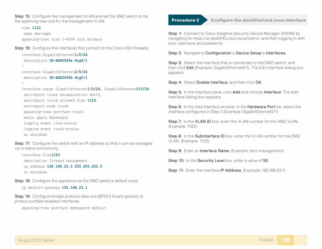
Procedure 2 Configure the demilitarized zone interface
Step 1: Connect to Cisco Adaptive Security Device Manager (ASDM) by navigating to https://ie-asa5545.cisco.local/admin, and then logging in with your username and password.
Step 2: Navigate to Configuration>DeviceSetup>Interfaces.
Step 3: Select the interface that is connected to the DMZ switch, and then click Edit(Example: GigabitEthernet0/1). The Edit Interface dialog box appears.
Step 4: Select EnableInterface, and then click OK .
Step 5: In the Interface pane, click Addand chooseInterface. The Add Interface dialog box appears.
Step 6: In the Add Interface window, in the HardwarePort list, select the interface configured in Step 3 (Example: GigabitEthernet0/1)
Step 7: In the VLANID box, enter the VLAN number for the DMZ VLAN. (Example: 1123)
Step 8: In the SubinterfaceID box, enter the VLAN number for the DMZ VLAN. (Example: 1123)
Step 9: Enter an InterfaceName. (Example: dmz-management)
Step 10: In the SecurityLevel box, enter a value of 50.
Step 11: Enter the interface IPAddress. (Example: 192.168.23.1)

19FirewallAugust 2012 Series 19
Step 12: Enter the interface SubnetMask , and then click OK . (Example: 255.255.255.0)
Step 13: Click Apply to save the configuration.
Step 14: Navigate to Configuration>DeviceManagement>HighAvailability>Failover.
Step 15: On the Interfaces tab, in the StandbyIPaddress column, enter the IP address of the standby unit for the interface you just created. (Example: 192.168.23.2)
Step 16: Select Monitored, and then click Apply.
Procedure 3 Configure the DMZ routing
Step 1: Navigate to Configuration>DeviceSetup>Routing>EIGRP>Setup.
Step 2: On the Networks tab, click Add.
Step 3: In the Add EIGRP Network dialog box, in the IPAddress box, enter the address that summarizes all DMZ networks. (Example: 192.168.16.0)
Step 4: In the Netmask box, enter the DMZ summary netmask, and then click OK . (Example: 255.255.248.0)
Step 5: In the Setup pane, click Apply. This saves the configuration.

20FirewallAugust 2012 Series 20
Procedure 4 Configure the DMZ security policy
Each security policy is unique to the policy and management requirements of an organization. Examples in this document are intended to illustrate policy configuration concepts.
Tech Tip
The management DMZ provides connectivity to the internal network for devices in the DMZ and outside the firewall. This connectivity is limited to the protocols required to maintain and operate the devices.
Step 1: Navigate to Configuration>Firewall>AccessRules.
First, you will enable devices in the management DMZ to communicate with the internal network for management and user authentication.
Step 2: Click Add,and then choose AddAccessRule.
Step 3: In the Add Access Rule dialog box, in the Interface list, select —Any—.
Step 4: For Action, select Permit.
Step 5: In the Source list, select the network object automatically created for the management DMZ. (Example: dmz-management-network/24)
Step 6: In the Destination list, select the network object that summarizes the internal networks. (Example: internal-network)
Step 7: In the Service list, enter tcp/ftp,tcp/ftp-data,tcp/tacacs,udp/ntp,udp/syslog, and then click OK .
Next, you will ease the configuration of the security policy by creating a network object that summarizes all the DMZ networks. All the DMZ networks deployed in SBA for Enterprise Organizations can be summarized as 192.168.16.0/21.
Step 8: Navigate to Configuration>Firewall>Objects>NetworkObjects/Groups.
Step 9: Click Add>NetworkObject.
Step 10: In the Add Network Object dialog box, in the Namebox , enter a description for the network summary. (Example: dmz-networks)
Step 11: In the Type list, select Network .
Step 12: In the IPAddress box, enter the address that summarizes all DMZ networks. (Example: 192.168.16.0)

21FirewallAugust 2012 Series 21
Step 13: In the Netmask box, enter the DMZ summary netmask, and then click OK . (Example: 255.255.248.0)
Next, you will deny access from the DMZs to all other networks, as open access poses a security risk.
Step 14: Navigate to Configuration>Firewall>AccessRules.
Step 15: Click Add>AddAccessRule.
Step 16: In the Add Access Rule dialog box, in the Interface list, select —Any—.
Step 17: For Action, select Deny.
Step 18: In the Source list, select the network object created in Step 9, and then click OK . (Example dmz-networks)
Step 19: In the Access Rules pane, click Apply. This saves the configuration.
Configuring the Firewall Internet Edge
1. Configure the outside switch
2. ASA with non-trunked Internet access
3. ASA with trunked Internet access
4. Configure address translation
5. Configure security policy
Process
Internet connectivity varies based on the organization’s availability require-ment for Internet access. Two options are available:
• Single ISP uses a single Internet connection via one router that carries the Internet traffic.
Figure 7 - Single ISP connectivity
30
05
VLAN 16172.16.0.0
OutsideSwitches
CiscoASA
PrimaryCiscoASAStandby
Internet
PrimaryISP Router
PrimaryISP

22FirewallAugust 2012 Series 22
• Dual ISP uses dual Internet connections via two routers (the primary and secondary ISP routers) that carry the Internet traffic.
Figure 8 - Dual ISP connectivity
30
06
OutsideSwitches
IP-SLA Probes
CiscoASA Standby
CiscoASA Primary
Internet
VLAN 16&17Trunked to Cisco ASA
ProbeDestination
172.18.1.1Primary
ISPSecondary
ISP
Primary ISPRouter
VLAN 16172.16.0.0
VLAN 17172.17.0.0
Secondary ISPRouter
An organization should have an IT security policy to use as a reference for defining its firewall policy. If there is no documented security policy, it is very difficult to create a firewall policy for the organization because no consistent set of rules can be enforced.
Policy Recommendations
Network security policies can be broken down into two basic categories: whitelist policies and blacklist policies. A whitelist-based policy offers a stronger initial security posture because all traffic is blocked except for applications that are explicitly allowed. However, whitelist policies are more likely to interfere with network applications and are more difficult to maintain, as each new application must be permitted through the firewall. A whitelist policy is easily recognized because the last access rule denies all traffic (i.e., “denyipanyany”). Whitelist policies are best suited for traffic from the Internet to services in the DMZ.
The following information is needed to be able to effectively define a whitelist security policy:
• What applications will be used on the network?
• Can their traffic be characterized at the protocol level?
• Is a detailed description of application behavior available in order to facilitate troubleshooting if the security policy interferes with the application?
A blacklist policy is generally more suitable for requests from the inside network to the Internet. This type of policy offers reduced operational burden and minimizes the likelihood that the security policy will interfere with Internet applications. Blacklist policies are the opposite of whitelist poli-cies; they only stop traffic that is explicitly denied. Typically an application is blocked because of an organization’s policy or because they expose the organization to malicious traffic. A blacklist policy is recognizable by the last access rule; the rule set permits all traffic that has not already been denied (that is, “permitipanyany”).
In some cases, traffic (such as web content) of high business value is very difficult to distinguish from traffic with no business value, such as malware and entertainment traffic. As an adjunct to the Cisco ASA, the Cisco Web Security Appliance (WSA) offers web filtering for traffic that contains malware or negatively affects user productivity. Additionally, Cisco IPS can be used to block malicious traffic embedded within permitted applica-tions. Cisco IPS concepts and configuration are discussed in the Intrusion Prevention chapter in this document. Cisco WSA concepts and configuration are discussed in the Cisco SBA—Borderless Networks Web Security Using WSA Deployment Guide.
Procedure 1 Configure the outside switch
If you already have a switch on the outside into which you are allowed to plug both Cisco ASAs, then you can skip this procedure. This switch could be ISP-provided gear, such as a cable modem with a 4-port switch or similar. The only requirement in Single ISP mode is that both Cisco ASAs’ outside interfaces have to be plugged into the same Layer-2 domain in order to allow failover to function. In this deployment, a trunked outside interface is used, even in Single ISP mode, to allow easier migration to Dual ISP mode later. If you are using an outside switch that doesn’t support trunking, you will need to assign the outside IP address directly to the interface of the Cisco ASA.

23FirewallAugust 2012 Series 23
For this procedure, if you are using a Single ISP design, you will skip the Dual ISP section. If you are using a Dual ISP design, you will complete both sets of steps.
Single ISP design
The outside switch in this deployment is a pair of 2960S switches in a stacked configuration. The configuration below is complete for the features required for the outside switch. This configuration is taken from the Cisco SBA—Borderless Networks LAN Deployment Guide.
Step 1: Set the stack master switch.
switch [switch number] priority 15
Step 2: Run the stack-macpersistenttimer0 command to ensure that the original master MAC address remains the stack MAC address after a failure.
stack-mac persistent timer 0
Step 3: To make consistent deployment of QoS easier, we define a macro that you will use in later steps to apply the specific QoS configuration. Because AutoQoS might not be configured on this device, run the following commands to manually configure the global QoS settings:
mls qos map policed-dscp 0 10 18 to 8mls qos map cos-dscp 0 8 16 24 32 46 48 56mls qos srr-queue input bandwidth 70 30mls qos srr-queue input threshold 1 80 90mls qos srr-queue input priority-queue 2 bandwidth 30mls qos srr-queue input cos-map queue 1 threshold 2 3mls qos srr-queue input cos-map queue 1 threshold 3 6 7mls qos srr-queue input cos-map queue 2 threshold 1 4mls qos srr-queue input dscp-map queue 1 threshold 2 24mls qos srr-queue input dscp-map queue 1 threshold 3 48 49 50 51 52 53 54 55mls qos srr-queue input dscp-map queue 1 threshold 3 56 57 58 59 60 61 62 63mls qos srr-queue input dscp-map queue 2 threshold 3 32 33 40 41 42 43 44 45mls qos srr-queue input dscp-map queue 2 threshold 3 46 47mls qos srr-queue output cos-map queue 1 threshold 3 4 5mls qos srr-queue output cos-map queue 2 threshold 1 2
mls qos srr-queue output cos-map queue 2 threshold 2 3mls qos srr-queue output cos-map queue 2 threshold 3 6 7mls qos srr-queue output cos-map queue 3 threshold 3 0mls qos srr-queue output cos-map queue 4 threshold 3 1mls qos srr-queue output dscp-map queue 1 threshold 3 32 33 40 41 42 43 44 45mls qos srr-queue output dscp-map queue 1 threshold 3 46 47mls qos srr-queue output dscp-map queue 2 threshold 1 16 17 18 19 20 21 22 23mls qos srr-queue output dscp-map queue 2 threshold 1 26 27 28 29 30 31 34 35mls qos srr-queue output dscp-map queue 2 threshold 1 36 37 38 39mls qos srr-queue output dscp-map queue 2 threshold 2 24mls qos srr-queue output dscp-map queue 2 threshold 3 48 49 50 51 52 53 54 55mls qos srr-queue output dscp-map queue 2 threshold 3 56 57 58 59 60 61 62 63mls qos srr-queue output dscp-map queue 3 threshold 3 0 1 2 3 4 5 6 7mls qos srr-queue output dscp-map queue 4 threshold 1 8 9 11 13 15mls qos srr-queue output dscp-map queue 4 threshold 2 10 12 14mls qos queue-set output 1 threshold 1 100 100 50 200mls qos queue-set output 1 threshold 2 125 125 100 400mls qos queue-set output 1 threshold 3 100 100 100 3200mls qos queue-set output 1 threshold 4 60 150 50 200mls qos queue-set output 1 buffers 15 25 40 20mls qos!macro name EgressQoS mls qos trust dscp queue-set 1 srr-queue bandwidth share 1 30 35 5 priority-queue out@!

24FirewallAugust 2012 Series 24
Step 4: Configure the device hostname to make it easy to identify the device.
hostname OUT-2960S
Step 5: Configure VTP transparent mode.
vtp mode transparent
Step 6: Configure Spanning-Tree (PVST+).
spanning-tree mode rapid-pvstspanning-tree vlan 1-4094 root primary
Step 7: Enable Unidirectional Link Detection (UDLD).
udld enable
Step 8: Set EtherChannels to use the traffic source and destination IP address.
port-channel load-balance src-dst-ip
Step 9: Configure device management protocols.
ip domain-name cisco.localip ssh version 2no ip http serverip http secure-serverline vty 0 15 transport input ssh transport preferred none
Simple Network Management Protocol (SNMP) is enabled to allow the network infrastructure devices to be managed by a Network Management System (NMS). SNMPv2c is configured both for a read-only and a read-write community string.
snmp-server community cisco RO snmp-server community cisco123 RW
Step 10: (Optional) In networks where network operational support is centralized you can increase network security by using an access list to limit the networks that can access your device. In this example, only devices on the 10.4.48.0/24 network will be able to access the device via SSH or SNMP.
access-list 55 permit 10.4.48.0 0.0.0.255line vty 0 15 access-class 55 in
!snmp-server community cisco RO 55 snmp-server community cisco123 RW 55
Step 11: Configure DNS for host lookup.
ip name-server 10.4.48.10
Step 12: Configure local login and password.
username admin password c1sco123enable secret c1sco123service password-encryptionaaa new-model
Step 13: (Optional) Configure centralized user authentication.
tacacs server TACACS-SERVER-1address ipv4 10.4.48.15key SecretKey!aaa group server tacacs+ TACACS-SERVERS server name TACACS-SERVER-1!aaa authentication login default group TACACS-SERVERS localaaa authorization exec default group TACACS-SERVERS localaaa authorization consoleip http authentication aaa
Step 14: Configure a synchronized clock.
ntp server 10.4.48.17!clock timezone PST -8 clock summer-time PDT recurring !service timestamps debug datetime msec localtimeservice timestamps log datetime msec localtime
Step 15: On the outside switch, configure the VLAN for the ISP.
vlan 16 name ISP-A

25FirewallAugust 2012 Series 25
Step 16: Configure the interface that is connected to the ISP router.
interface GigabitEthernet1/0/23 description ISP-A switchport access vlan 16 switchport host no cdp enable
Step 17: Configure the interfaces that connect to the appliances.
interface GigabitEthernet1/0/24 description IE-ASA5545a Gig0/3!interface GigabitEthernet2/0/24 description IE-ASA5545b Gig0/3!interface range GigabitEthernet1/0/24, GigabitEthernet2/0/24 switchport trunk allowed vlan 16 switchport mode trunk spanning-tree portfast trunk macro apply EgressQoS logging event link-status logging event trunk-status no shutdown
Step 18: Configure the switch with an IP address so that it can be managed via out-of-band connectivity.
interface FastEthernet0 description to DMZ-3750X Gig1/0/17 ip address 192.168.23.6 255.255.255.0 no shutdown
Step 19: Configure the appliance as the DMZ switch’s default route.
ip default-gateway 192.168.23.1
Step 20: On the DMZ switch, configure the interface connected to the outside switch to be in the management DMZ.
interface GigabitEthernet1/0/17 description OUT-2960Sa Fas0!interface GigabitEthernet2/0/17 description OUT-2960Sb Fas0!interface range GigabitEthernet1/0/17, GigabitEthernet2/0/17 switchport access vlan 1123 switchport host no shutdown
Step 21: On the outside switch, configure BPDU Guard globally to protect portfast-enabled interfaces.
spanning-tree portfast bpduguard default
If you are using a single ISP, you can skip to the next procedure.
Dual ISP design
Step 22: On the outside switch, add the VLAN for the backup ISP.
vlan 17 name ISP-B
Step 23: Configure the interface that connects to the ISP router.
interface GigabitEthernet2/0/23 description ISP-B switchport access vlan 17 switchport host no cdp enable
Step 24: Configure the interfaces that connect to the appliances.
interface range GigabitEthernet1/0/24, GigabitEthernet2/0/24 switchport trunk allowed vlan add 17 no shutdown

26FirewallAugust 2012 Series 26
Procedure 2 ASA with non-trunked Internet access
If you are using a non-trunked single ISP design, complete this procedure. If you are using a trunked design using either single or dual ISPs, skip to Procedure 3.
Step 1: From a client on the internal network, navigate to the firewall’s inside IP address, and then launch the Cisco ASA Security Device Manager. (Example: https://ie-asa5545.cisco.local/)
Step 2: In Configuration>DeviceSetup>Interfaces, click the interface that is connected to the outside switch. (Example: GigabitEthernet0/3)
Step 3: Click Edit.
Step 4: In the Edit Interface dialog box, select EnableInterface.
Step 5: Enter an InterfaceName. (Example: outside)
Step 6: In the SecurityLevel box, enter a value of 0.
Step 7: Enter the interface IPAddress. (Example: 172.16.130.124)
Step 8: Enter the interface SubnetMask , and then clickOK . (Example: 255.255.255.0)
Step 9: On the Interface pane, click Apply.
Step 10: Navigate to Configuration>DeviceManagement>HighAvailability>Failover.
Step 11: On the Interfaces tab, in the StandbyIPAddress column, enter the IP address of the standby unit for the interface you just created. (Example: 172.16.130.123)

27FirewallAugust 2012 Series 27
Step 12: Select Monitored,andthenclickApply.
Next, you will create the default route to the primary Internet CPE’s address.
Step 13: In Configuration>DeviceSetup>Routing>StaticRoutes, click Add.
Step 14: In the Add Static Route dialog box, in the Interface list, choose the interface edited in Step 2 (Example: outside)
Step 15: In the Network box, enter 0.0.0.0/0.0.0.0.
Step 16: In the GatewayIP box, enter the primary Internet CPE’s IP address, and then click OK . (Example: 172.16.130.126)
Step 17: On the Static Routes pane, click Apply.

28FirewallAugust 2012 Series 28
Procedure 3 ASA with trunked Internet access
If you are configuring the ASA outside connectivity for a trunked single ISP design complete option 1. If using a trunked dual ISP design, then complete both option 1 and then option 2 for the second ISP.
Option 1. Using a Single ISP, trunked design
Step 1: From a client on the internal network, navigate to the firewall’s inside IP address, and then launch the Cisco ASA Security Device Manager. (Example: https://ie-asa5545.cisco.local/)
Step 2: In Configuration>DeviceSetup>Interfaces, click the interface that is connected to the outside switch. (Example: GigabitEthernet0/3)
Step 3: Click Edit.
Step 4: In the Edit Interface dialog box, select EnableInterface, and then click OK .
Step 5: On the Interface pane, click Add>Interface.
Step 6: In the Add Interface dialog box, in the HardwarePort list, select the interface enabled in Step 4. (Example: GigabitEthernet0/3)
Step 7: In the VLANID box, enter the VLAN number for the primary Internet VLAN. (Example: 16)
Step 8: In the SubinterfaceID box, enter the VLAN number for the primary Internet VLAN. (Example: 16)
Step 9: Enter an InterfaceName. (Example: outside-16)
Step 10: In the SecurityLevel box, enter a value of 0.
Step 11: Enter the interface IPAddress. (Example: 172.16.130.124)
Step 12: Enter the interface SubnetMask , and then clickOK . (Example: 255.255.255.0)
Step 13: On the Interface pane, click Apply.
Step 14: Navigate to Configuration>DeviceManagement>HighAvailability>Failover.
Step 15: On the Interfaces tab, in the StandbyIPAddress column, enter the IP address of the standby unit for the interface you just created. (Example: 172.16.130.123)

29FirewallAugust 2012 Series 29
Step 16: Select Monitored,andthenclickApply.
Next, you will create the default route to the primary Internet CPE’s address.
Step 17: In Configuration>DeviceSetup>Routing>StaticRoutes, click Add.
Step 18: In the Add Static Route dialog box, in the Interface list, chose the interface created in Step 9 (Example: outside-16)
Step 19: In the Network box, enter 0.0.0.0/0.0.0.0.
Step 20: In the GatewayIP box, enter the primary Internet CPE’s IP address, and then click OK . (Example: 172.16.130.126)
Step 21: On the Static Routes pane, click Apply.
Option 2. Using a Trunked Dual ISP design
If Dual ISP access is not being used, skip to Procedure 4. This procedure assumes that the configuration in Procedure 3 Option 1: was completed for the primary ISP connection.
When resilient Internet access (Dual ISP) is required, the appliances’ GigabitEthernet 0/3, which is configured as a VLAN trunk to the outside switch, is assigned an additional VLAN to use to connect to the secondary ISP. The VLAN trunk allows the appliance to use separate VLANs for the upstream internet routers.
The primary route carries a metric of 1, making the route preferred; the pri-mary route’s availability is determined by the state of the ‘track 1’ object that is appended to the primary route. The route-tracking configuration defines a target in ISP-1’s network to which the appliance sends ICMP probes (pings) in order to determine if the network connection is active. The target is an object on the primary service provider’s network, such as an intermediate router that can be discovered with traceroute.

30FirewallAugust 2012 Series 30
The tracked object should be in the primary ISP’s network. The point of tracking an object in the primary ISP’s network is because if reachability to this object is available, then all connectivity to that point is working, includ-ing: the appliance’s connection to the customer premise router, the WAN connection, and most routing inside the ISP’s network. If the tracked object is unavailable, it is likely that the path to the primary ISP is down, and the appliance should prefer the secondary ISP’s route.
Step 1: Navigate to Configuration>DeviceSetup>Interfaces.
Step 2: On the Interface pane, click Add>Interface.
Step 3: In the Add Interface dialog box, in the HardwarePort list, choose the interface configured in Step 4. (Example: GigabitEthernet0/3)
Step 4: In the VLANID box, enter the VLAN number for the resilient Internet VLAN. (Example: 17)
Step 5: In the SubinterfaceID box, enter the VLAN number for the resilient Internet VLAN. (Example: 17)
Step 6: Enter an InterfaceName. (Example: outside-17)
Step 7: In the SecurityLevel box, enter a value of 0.
Step 8: Enter the interface IPAddress. (Example: 172.17.130.124)
Step 9: Enter the interface SubnetMask , and then clickOK . (Example: 255.255.255.0)
Step 10: On the Interface pane, click Apply.
Step 11: Navigate to Configuration>DeviceManagement>HighAvailability>Failover.
Step 12: On the Interfaces tab, in the StandbyIPAddress column, enter the IP address of the standby unit for the interface you just created. (Example: 172.17.130.123)

31FirewallAugust 2012 Series 31
Step 13: Select Monitored, and then click Apply.
Next, you will edit the default route to the primary Internet CPE’s address.
Step 14: Navigate to Configuration>DeviceSetup>Routing>StaticRoutes.
Step 15: Select the default route created in Step 20, and click Edit.
Step 16: In the Edit Static Route dialog box, in the Options pane, select Tracked.
Step 17: In the TrackID box, enter 1.
Step 18: In the TrackIPAddress box, enter an IP address in the ISP’s cloud. (Example: 172.18.1.1)
Step 19: In the SLAID box, enter 16.
Step 20: In the TargetInterface list, select the primary Internet connection interface, and then click OK . (Example: outside-16)
Step 21: On the Information dialog box, click OK .
Next, you will create the secondary default route to the resilient Internet CPE’s address.
Step 22: In Configuration>DeviceSetup>Routing>StaticRoutes, click Add.
Step 23: In the Add Static Route dialog box, in the Interface list, select the resilient Internet connection interface created in Step 6. (Example: outside-17)
Step 24: In the Network box, enter 0.0.0.0/0.0.0.0.
Step 25: In the GatewayIP box, enter the primary Internet CPE’s IP address. (Example: 172.17.130.126)

32FirewallAugust 2012 Series 32
Step 26: In the Metric box, enter 254, and then click OK .
Step 27: On the Static Routes pane, click Apply.
Next, you will add a host route for the tracked object via the Internet-CPE-1 address. This assures that probes to the tracked object will always use the primary ISP connection.
Step 28: In Configuration>DeviceSetup>Routing>StaticRoutes, click Add.
Step 29: In the Add Static Route dialog box, in the Interface list, select the primary Internet connection interface created in Step 9. (Example: outside-16)
Step 30: In the Network box, enter the IP address used for tracking in the primary default route. (Example: 172.18.1.1/32)
Step 31: In the GatewayIP box, enter the primary Internet CPE’s IP address, and then click OK . (Example: 172.16.130.126)
Step 32: On the Static Routes pane, click Apply.
Step 33: In Cisco ASDM, refresh the configuration.
Step 34: You can monitor the reachability of the tracked object by navigat-ing to Monitoring>Interfaces>Connectionoutside-16>TrackStatusforid-1.

33FirewallAugust 2012 Series 33
Procedure 4 Configure address translation
Prior to completing this procedure, access to the Internet from within the inside network is not possible. This procedure is required to permit Internet traffic for the inside network and the DMZs; the inside and DMZ networks are numbered using private (RFC 1918) addressing that is not Internet-routable, so the appliances must translate the private addresses to outside Internet-routable addresses. For this configuration, all inside addresses are translated to the public address on the outside interface.
As the address translation configuration described in this portion of the document is applied, the appliance enables its default access rule set. Review the expected traffic carefully; if any traffic allowed by the default rules should not be permitted, shut down the interfaces until the firewall rule set is completely configured.
Tech Tip
NAT configuration varies depending on whether a Single or Dual ISP con-figuration is used. Most of the configuration is common to both designs, although there are some additional steps for configuring both outside interfaces in the Dual ISP design.
Step 1: Navigate to Configuration>Firewall>Objects>NetworkObjects/Groups.
Step 2: Click Add>NetworkObject.
Step 3: In the Add Network Object dialog box, in the Namebox , enter a description for the address translation. (Example: internal-network-ISPa)
Step 4: In the Type list, select Network .
Step 5: In the IPAddress box, enter the address that summarizes all internal networks. (Example: 10.4.0.0)
Step 6: In the Netmask box, enter the internal summary netmask. (Example: 255.254.0.0)
Step 7: Click the two down arrows. The NAT pane expands.
Step 8: Select AddAutomaticAddressTranslationRules.
Step 9: In the Type list, select DynamicPAT(Hide).
Step 10: In the TranslatedAddr. box, enter the name of the primary Internet connection interface, and then click OK . (Example: outside-16)
Step 11: On the Network Objects/Groups pane, click Apply.
Step 12: If you are using a Single ISP design, continue to Procedure 5.
If you are using the Dual ISP design, repeat Step 1 - Step 11 for the resilient Internet connection, using the correct input for the alternate Internet con-nection. (Example: internal-network-ISPb, outside-17)

34FirewallAugust 2012 Series 34
Procedure 5 Configure security policy
The security policy is typically configured so that internal network traffic to the DMZs or Internet is blocked only for high-risk services; all other access is allowed.
Telnet is an example of a network service that is high-risk, because it carries all of its data unencrypted. This poses a risk because hosts that can inter-cept the data can potentially view sensitive data.
Step 1: Navigate to Configuration>Firewall>AccessRules.
First, you will add a rule to deny the internal network from sending outbound Telnet requests.
Step 2: Click Add>AddAccessRule.
Step 3: In the Add Access Rule dialog box, in the Interface list, select —Any—.
Step 4: For Action, select Deny.
Step 5: In the Source list, select the network object that summarizes the internal networks. (Example: internal-network)
Step 6: In the Service list, enter tcp/telnet, and then click OK .
Next, you will add a rule to permit all remaining traffic from the internal network.
Step 7: Click Add>AddAccessRule.
Step 8: In the Add Access Rule dialog box, in the Interface list, select —Any—.
Step 9: For Action, select Permit.
Step 10: In the Source list, select the network object that summarizes the internal networks. (Example: internal-network)
Step 11: Clear EnableLogging, and then click OK.
Step 12: On the Access Rules pane, click Apply.

35FirewallAugust 2012 Series 35
Configuring the Web DMZ
1. Configure the DMZ switch
2. Configure DMZ interface
3. Configure Network Address Translation
4. Configure security policy
Process
The firewall’s demilitarized zone (DMZ) is a portion of the network where, typically, traffic to and from other parts of the network is tightly restricted. Organizations place network services in a DMZ for exposure to the Internet. These servers are typically not allowed to initiate connections to the inside network, except for specific circumstances.
In this process a DMZ is configured to enable you to host Internet-accessible web servers to be on site.
The DMZ network is connected to the appliances on the appliances’ GigabitEthernet interface via a VLAN trunk in order to allow the greatest flex-ibility if new VLANs must be added to connect additional DMZs. The trunk connects the appliances to a 3750x access-switch stack in order to provide resiliency. The DMZ VLAN interfaces on the Cisco ASA are each assigned an IP address that is the default gateway for each of the VLAN subnets. The DMZ switch only offers Layer-2 switching capability; the DMZ switch’s VLAN interfaces do not have an IP address assigned, except for one VLAN inter-face with an IP address for management of the switch.
Figure 9 - Web DMZ VLAN topology
30
07
DMZ VLANTrunk
DMZSwitches
DMZWeb
Servers
DistributionSwitches
Cisco ASA
Internet
The number of secure VLANs is arbitrary. The following deployment illustrates an example of one secured network. If multiple types of hosts are to be connected in an Internet-facing DMZ, segmenting the DMZ along functional boundaries may be necessary, particularly because hosts that are exposed to the Internet are vulnerable to compromise and must not offer a springboard to other hosts. However, traffic between DMZ VLANs should be kept to a minimum. Placing servers that must share data on a single VLAN improves performance and reduces load on network devices.
Setting the DMZ connectivity as a VLAN trunk offers the greatest flexibility.
Tech Tip

36FirewallAugust 2012 Series 36
Procedure 1 Configure the DMZ switch
This procedure assumes that the DMZ switch has already been configured following the guidance in Procedure 1, Configure the DMZ switch.
Step 1: Configure the DMZ Web VLAN on the DMZ switch
vlan 1116 name dmz-web
Step 2: Configure the interfaces that connect to the appliances.
interface range GigabitEthernet1/0/24, GigabitEthernet2/0/24 switchport trunk allowed vlan add 1116
Step 3: Configure the interfaces that are connected to the web servers.
interface GigabitEthernet1/0/2 description Webserver switchport access vlan 1116 switchport host macro apply EgressQoS logging event link-status no shutdown
Procedure 2 Configure DMZ interface
Step 1: Connect to Cisco Adaptive Security Device Manager (ASDM) by navigating to https://ie-asa5545.cisco.local/admin, and then logging in with your username and password.
Step 2: Navigate to Configuration>DeviceSetup>Interfaces.
Step 3: On the Interface pane, click Add>Interface.
Step 4: In the Add Interface dialog box, in the HardwarePort list, choose the interface connected to the DMZ switch.(Example: GigabitEthernet0/1)
Step 5: In the VLANID box, enter the VLAN number for the DMZ VLAN. (Example: 1116)
Step 6: In the SubinterfaceID box, enter the VLAN number for the DMZ VLAN. (Example: 1116)
Step 7: Enter an InterfaceName. (Example: dmz-web)
Step 8: In the SecurityLevel box, enter a value of 50.
Step 9: Enter the interface IPAddress. (Example: 192.168.16.1)
Step 10: Enter the interface SubnetMask , and then clickOK . (Example: 255.255.255.0)
Step 11: On the Interface pane, click Apply.
Step 12: Navigate to Configuration>DeviceManagement>HighAvailability>Failover.
Step 13: On the Interfaces tab, in the StandbyIPaddress column, enter the IP address of the standby unit for the interface you just created. (Example: 192.168.16.2)

37FirewallAugust 2012 Series 37
Step 14: Select Monitored, and then click Apply.
Procedure 3 Configure Network Address Translation
The DMZ network uses private network (RFC 1918) addressing that is not Internet-routable, so the firewall must translate the DMZ address of the web server to an outside public address. If there is a resilient Internet connection, the web server can have an address translation for each ISP. This resilient configuration, shown here for completeness, relies on the modification of DNS records in order to point incoming requests to the resilient web server address when the primary Internet connection is unavailable.
The example DMZ address to public IP address mapping is shown in the following table.
Table 3 - DMZ address mapping
Web server DMZ address Web server public address (externally routable after NAT)
192.168.16.100 172.16.130.100 (ISP-A)
172.17.130.100 (ISP-B for Dual ISP only)
Step 1: Navigate to Configuration>Firewall>Objects>NetworkObjects/Groups.
First, you will add a network object for the web server’s IP address on the primary Internet connection.
Step 2: Click Add>NetworkObject.
Step 3: On the Add Network Object dialog box, in the Namebox , enter a description for the web server’s public IP address. (Example: outside-webserver-ISPa)
Step 4: In the Type list, select Host.
Step 5: In the IPAddress box, enter the web server’s public IP address, and then click OK . (Example: 172.16.130.100)
Step 6: On the Network Objects/Groups pane, click Apply.

38FirewallAugust 2012 Series 38
Next, you will add a network object for the private DMZ address of the web server.
Step 7: Click Add>NetworkObject.
Step 8: On the Add Network Object dialog box, in the Namebox ,enter a description for the web server’s private DMZ IP address. (Example: dmz-webserver-ISPa)
Step 9: In the Type list, select Host.
Step 10: In the IPAddress box, enter the web server’s private DMZ IP address. (Example: 192.168.16.100)
Step 11: Click the two down arrows. The NAT pane expands.
Step 12: Select AddAutomaticAddressTranslationRules.
Step 13: In the TranslatedAddr list, select the network object created in Step 2. (Example: outside-webserver-ISPa)
Step 14: Click Advanced.
Step 15: In the Advanced NAT Settings dialog box, in the DestinationInterface list, select the interface name for the primary Internet connection, and then click OK . (Example: outside-16)
Step 16: In the Add Network Object dialog box, click OK .
Step 17: On the Network Objects/Groups pane, click Apply.
Step 18: If you are using the Dual ISP design with a resilient internet con-nection, repeat this procedure for the secondary Internet connection.
If you are using the Single ISP design, proceed to Procedure 4.
Procedure 4 Configure security policy
The web DMZ offers HTTP and HTTPS service for the Internet. This could provide capabilities to support employee/partner web-portal access, basic customer service and support, small-scale eCommerce or B2B service, or other appropriate tasks.
Step 1: Navigate to Configuration>Firewall>AccessRules.
Step 2: Click the rule that denies traffic from the DMZ toward other networks.

39FirewallAugust 2012 Series 39
Step 3: Click Add>Insert.
Step 4: In the Insert Access Rule dialog box, in the Interface list, select —Any—.
Step 5: For Action, select Permit.
Step 6: In the Destination list, select the network object automatically created for the web DMZ. (Example: dmz-web-network/24)
Step 7: In the Service list, enter tcp/http,tcp/https, and then click OK .
Step 8: On the Access Rules pane, click Apply.
Firewall SummaryThis section described concepts and configuration for:
• Routing to the Internet.
• Firewall management and monitoring.
• Inside-network NAT and firewall policy recommendations.
• DMZ configuration for internet-accessible web servers.

40Intrusion PreventionAugust 2012 Series 40
Intrusion Prevention
Business OverviewInternet services have become a key part of day-to-day operations for many organizations today. Providing secure Internet access, while preventing malicious content from entering an organization is critical to maintaining employee productivity. In addition to client access to the Internet, orga-nizations have near-universal need to have a web presence available for partners and clients to access information about the organization. Placing corporate information on the Internet runs a risk of exposure of data through an attack on the public-facing services. For an organization to utilize the Internet effectively, solutions must be found for all of these concerns.
Technology OverviewWorms, viruses, and botnets pose a substantial threat to organizations. To minimize the impact of network intrusions, you can deploy intrusion prevention systems (IPSs) in order to provide additional protection for the organization from the traffic that is permitted through the Internet edge firewall. Cisco IPS technology complements the firewall and inspects traffic permitted by the firewall policy, for attacks.
Cisco IPS devices come in two formats: standalone appliances and hard-ware or software modules inside a Cisco ASA firewall. The differences between the devices generally revolve around how the devices get the traffic they inspect. An appliance uses physical interfaces that exist as part of the network. A module receives traffic from the ASA firewall in which it resides, according to the policy defined on the firewall.
With either type of device, there are two deployment modes available: promiscuous (IDS) or inline (IPS). There are specific reasons for each deployment mode, based on risk tolerance and fault tolerance. Inline or IPS mode means that the IPS device sits inline on the traffic flow in order to inspect the actual packets, and if an alert is triggered that includes a drop action, the IPS device can drop the actual malicious packet. Promiscuous or IDS mode (note that an IPS device can operate in IDS mode) means that an external device is copying the packets to the IPS device. For an appliance, the way packets get copied is generally a network tap or a switch running a SPAN session. For a module, the copying happens at the Cisco ASA firewall
and is controlled by the ASA configuration. Because inline and promiscuous are operating modes, an IPS device can inspect traffic at multiple places, and each inspection point could be set up independently as inline or promiscuous.
Using inline mode means that network traffic flows through an IPS device, and if the device fails or misbehaves, it will impact production traffic. The advantage inline mode offers is that when the sensor detects malicious behavior, the sensor can simply drop it. This allows the IPS device a much greater capacity to actually prevent attacks.
Using promiscuous mode means that the IPS device must use another inline enforcement device in order to stop malicious traffic. This means that for activity such as single-packet attacks (slammer worm over User Datagram Protocol), an IDS sensor could not prevent the attack from occurring. However, an IDS sensor can offer great value when identifying and cleaning up infected hosts.
This design uses the Cisco ASA 5500 Series IPS Solution (software module inside an ASA) at the Internet edge. The design offers several options that are based on the performance requirements of the organization. It is impor-tant to remember that the Internet edge firewall and IPS have more than just employee Internet traffic going through the box. Internal traffic to servers in the DMZ, wireless guest traffic, site-to-site VPN, and remote-access VPN traffic all combine to make the throughput requirements for the Internet edge firewall and IPS much higher than Internet connection speed.
You will also deploy the standalone Cisco IPS 4300 Series Sensors in pro-miscuous mode. The ability to deploy a sensor internally on the network in order to watch traffic on any distribution switch can be very valuable. These sensors can be used to watch traffic going to and from the WAN network, traffic on the wireless network, or even traffic on a B2B network to a partner.

41Intrusion PreventionAugust 2012 Series 41
Figure 10 - Packet flow through a Cisco ASA firewall and IPS module
30
08
12
3
4
5
6
Traffic is inspected by Cisco ASA firewall policy
If denied by firewall policy, traffic is dropped
Permitted traffic matching inspection policy is sent to Cisco IPS module
Traffic that matches the reputation filter list or has a GC adjusted risk rating of 90+ is dropped
Clean traffic is sent back to Cisco ASA
If present, VPN access policies are applied, and then traffic is forwarded onto network
1
2
3
4
5
6
IPS services integrated into the ASA firewall rely on the firewalls for high availability services. The firewalls in the Internet edge are deployed in an active/standby configuration; if the primary firewall fails, then the second-ary firewall will take over all firewall operations, and the IPS module in the secondary firewall inspects the traffic.
Figure 11 - IPS processing flowchart
Pre-Processing
Cisco IPS Reputation Filters
SignatureInspection
AnomolyDetection
GlobalCorrelation
DecisionEngine
30
10
Cisco IPS can make informed decisions on whether to permit or block traffic based off of reputation. Cisco IPS uses reputation in two key ways:
• ReputationFilters—a small list of IP addresses that have been hijacked or are owned by malicious groups
• GlobalCorrelationInspection—a rating system for IP addresses based off of prior behavior
Reputation Filters allow the IPS to block all traffic from known bad addresses before any significant inspection is done. Global Correlation Inspection uses the reputation of the attacker in conjunction with the risk rating associated with the signature in order to determine a new risk rating and drop traffic that is likely to be malicious.
Because Global Correlation Inspection depends on actual public IP addresses to function, any sensor that is deployed internally and sees only private addresses should have Global Correlation Inspection disabled because it will not add any value.

42Intrusion PreventionAugust 2012 Series 42
Figure 12 - Reputation effect on risk rating
8081828384858687888990919293949596979899
100
-0.5
8081828384858687888990919293949596979899
100
-1
8081828384858687888990919293949596979899
100
-1.5
8484858586878788888990919293949596979899
100
-2
8787888889909091919292939394959596979899
100
-2.5
9090919192929293939494959596969697979899
100
-3
929293939494949595969697979798989999
100100100
-3.5
94949595959696969797979898999999
100100100100100
-4
95969696979797989898999999
100100100100100100100100
-4.5
97979798989898999999
100100100100100100100100100100100
-5
98989899999999
100100100100100100100100100100100100100100
-5.5
99999999
100100100100100100100100100100100100100100100100100
-6
99100100100100100100100100100100100100100100100100100100100100
-6.5
100100100100100100100100100100100100100100100100100100100100100
-7
100100100100100100100100100100100100100100100100100100100100100
-7.5
100100100100100100100100100100100100100100100100100100100100100
-8
100100100100100100100100100100100100100100100100100100100100100
-8.5
100100100100100100100100100100100100100100100100100100100100100
-9
100100100100100100100100100100100100100100100100100100100100100
-9.5
100100100100100100100100100100100100100100100100100100100100100
-10
100100100100100100100100100100100100100100100100100100100100100
Reputation Effect on Risk RatingStandard Mode Reputation of Attacker
InitialRiskRating
Blue Deny Packet Red Deny Attacker
30
12
For more information about how traffic moves through the Cisco ASA and IPS module combination, see the following: http://www.cisco.com/en/US/docs/security/asa/asa84/asdm64/configura-tion_guide/modules_ips.html#wp1087140
Reader Tip
Deployment DetailsIn this deployment, you will deploy Cisco ASA IPS modules in inline mode in order to block inbound attacks to the Internet services in the DMZ. You will also deploy a standalone IPS appliance in promiscuous mode on the inside of the network. This appliance will be attached to a distribution switch and will watch for possible malicious activity in the traffic traversing the switch. The appliance is deployed on the WAN aggregation switch so that it can inspect the traffic going between the campus and remote sites. This could just as easily be deployed to watch other LAN sites, the traffic from the DMVPN connection, wireless traffic (after it enters the wired LAN), or possibly partner connections. Because it is possible to send too much traffic to an IPS device (too much for either the port or the hardware to handle), it is important to size the device care-fully. The following tables give estimated performance for different models.
Table 4 - Performance levels
Cisco IPS appliance model Average Inspection Throughput
IPS 4345 750 Mbps
IPS 4360 1.25 Gbps
IPS 4510 3 Gbps
IPS 4520 5 Gbps
Cisco ASA 5500 Series IPS Solution module Firewall + IPS Throughput
ASA 5512-X 250 Mbps
ASA 5515-X 400 Mbps
ASA 5525-X 600 Mbps
ASA 5545-X 900 Gbps
For the Cisco IPS 4345 in this deployment, we use 2 gigabit interfaces, where each is attached to one of the switches in the switch stack. If faster models are used, options include either using a ten-gigabit interface or using a port channel of 2 or more gigabit interfaces (these options are switch-dependent, as some switches and code versions do not support using port channels as destinations for Switched Port Analyzer sessions).
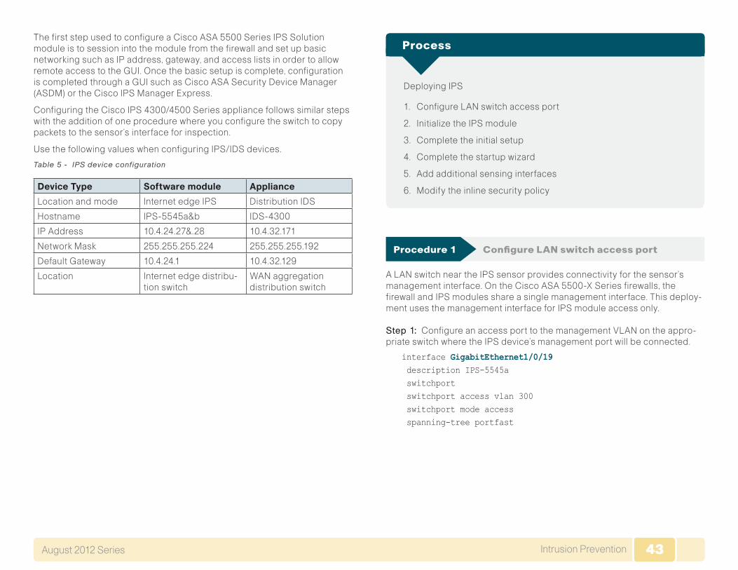
43Intrusion PreventionAugust 2012 Series 43
The first step used to configure a Cisco ASA 5500 Series IPS Solution module is to session into the module from the firewall and set up basic networking such as IP address, gateway, and access lists in order to allow remote access to the GUI. Once the basic setup is complete, configuration is completed through a GUI such as Cisco ASA Security Device Manager (ASDM) or the Cisco IPS Manager Express.
Configuring the Cisco IPS 4300/4500 Series appliance follows similar steps with the addition of one procedure where you configure the switch to copy packets to the sensor’s interface for inspection.
Use the following values when configuring IPS/IDS devices.
Table 5 - IPS device configuration
Device Type Software module Appliance
Location and mode Internet edge IPS Distribution IDS
Hostname IPS-5545a&b IDS-4300
IP Address 10.4.24.27&.28 10.4.32.171
Network Mask 255.255.255.224 255.255.255.192
Default Gateway 10.4.24.1 10.4.32.129
Location Internet edge distribu-tion switch
WAN aggregation distribution switch
Deploying IPS
1. Configure LAN switch access port
2. Initialize the IPS module
3. Complete the initial setup
4. Complete the startup wizard
5. Add additional sensing interfaces
6. Modify the inline security policy
Process
Procedure 1 Configure LAN switch access port
A LAN switch near the IPS sensor provides connectivity for the sensor’s management interface. On the Cisco ASA 5500-X Series firewalls, the firewall and IPS modules share a single management interface. This deploy-ment uses the management interface for IPS module access only.
Step 1: Configure an access port to the management VLAN on the appro-priate switch where the IPS device’s management port will be connected.
interface GigabitEthernet1/0/19 description IPS-5545a switchport switchport access vlan 300 switchport mode access spanning-tree portfast

44Intrusion PreventionAugust 2012 Series 44
Step 2: Configure the LAN distribution switch interfaces that are connected to the Cisco ASA management interface to allow access to the IPS module for management.
interface GigabitEthernet1/0/19 description IPS-5545a!interface GigabitEthernet2/0/19 description IPS-5545b!interface range GigabitEthernet1/0/19, GigabitEthernet2/0/19 switchport access vlan 300 switchport mode access spanning-tree portfast
The IPS module and the Cisco ASA share the same physical port for management traffic. In this deployment, the ASA is managed in-band and the IPS, either module or appliance, is always man-aged from the dedicated management port.
Tech Tip
Procedure 2 Initialize the IPS module
When a Cisco ASA 5500 Series IPS Solution is initially deployed, the soft-ware IPS module may not be initialized, resulting in the ASA firewall being unaware of what code version to boot for the IPS module. This procedure verifies the IPS module status and prepares for configuration completion.
Step 1: From the Cisco ASA command line interface, run the following command.
IE-ASA5545X# sho module ips detail
Step 2: If the status shown below is Up, then the IPS module software has been loaded and you can skip to Procedure 3.
IE-ASA5545X# sho module ips detailGetting details from the Service Module, please wait...
Card Type: ASA 5545-X IPS Security Services ProcessorModel: ASA5545-IPSHardware version: N/ASerial Number: FCH161170MAFirmware version: N/ASoftware version: 7.1(4)E4MAC Address Range: c464.1339.a354 to c464.1339.a354App. name: IPSApp. Status: UpApp. Status Desc: Normal OperationApp. version: 7.1(4)E4Data Plane Status: UpStatus: Up
If the status shown is Status:UnresponsiveNoImagePresent, then the IPS module software has never been loaded. Continue to the next step.
IE-ASA5545X# sho module ips detailGetting details from the Service Module, please wait...Unable to read details from module ips
Card Type: UnknownModel: N/AHardware version: N/ASerial Number: FCH16097J3FFirmware version: N/ASoftware version:MAC Address Range: c464.1339.2cf1 to c464.1339.2cf1Data Plane Status: Not ApplicableStatus: Unresponsive No Image Present...

45Intrusion PreventionAugust 2012 Series 45
Step 3: Verify you have the correct IPS image on the Cisco ASA firewall disk0:.
IE-ASA5545X# dirDirectory of disk0:/113 -rwx 34523136 16:55:06 Apr 19 2012 asa861-smp-k8.bin114 -rwx 42637312 16:57:00 Apr 19 2012 IPS-SSP_5545-K9-sys-1.1-a-7.1-4-E4.aip115 -rwx 17851400 16:57:32 Apr 19 2012 asdm-66114.bin123 -rwx 34523136 13:40:30 May 22 2012 asa861-1-smp-k8.bin
Step 4: Configure the IPS module to load the software on disk0: and then boot with that software.
IE-ASA5545X# sw-module module ips recover configure image disk0:/IPS-SSP_5545-K9-sys-1.1-a-7.1-4-E4.aipIE-ASA5545X# sw-module module ips recover boot
Module ips will be recovered. This may erase all configuration and all data on that device and attempt to download/install a new image for it. This may take several minutes.
Recover module ips? [confirm]yRecover issued for module ips.
Step 5: After a few minutes, run the following command, and then verify that the module status is Up.
Show module ips detail
Procedure 3 Complete the initial setup
The initial setup will involve configuring each IPS device (module or appli-ance with the initial networking information to allow the use of the GUI to complete the configuration.
Table 6 - IPS device configuration
Internet Edge IPS Distribution IDS
Device Type Software module Appliance
Hostname IPS-5545a&b IDS-4300
IP Address 10.4.24.27&.28 10.4.32.171
Network Mask 255.255.255.224 255.255.255.192
Default Gateway 10.4.24.1 10.4.32.129
Location Internet Edge distribution switch
WAN aggregation distribution switch
Step 1: If you are using the Cisco ASA 5545-X, log into the ASA appliance, and then access the IPS module by issuing the following command.
ASA5545# session ipsOpening command session with module ips.Connected to module ips. Escape character sequence is ‘CTRL-^X’.
If you are using a Cisco IPS 4x00 Series appliance, open a CLI session on the sensor’s console port.

46Intrusion PreventionAugust 2012 Series 46
The default username and password for the IPS module is cisco/cisco. If this is the first time the sensor has been logged into, there will be a prompt to change the password. Enter the current password, and then input a new password. Change the password to a value that complies with the security policy of the organization.
login: cisco Password:[password]
Tech Tip
Step 2: Run the setup command for either the module or an IPS appliance.
sensor# setupEnter host name[sensor]: IPS-5545a Enter IP interface[]: 10.4.24.27/27,10.4.24.1Modify current access list?[no]: yes Current access list entries: No entries Permit: 10.4.48.0/24Permit: Use DNS server for Global Correlation?[no]: yes DNS server IP address[]: 10.4.48.10 Use HTTP proxy server for Global Correlation?[no]: noModify system clock settings?[no]: noParticipation in the SensorBase Network allows Cisco to collect aggregated statistics about traffic sent to your IPS. SensorBase Network Participation level?[off]: partial...Do you agree to participate in the SensorBase Network?[no]:yes...[0] Go to the command prompt without saving this config. [1] Return to setup without saving this config. [2] Save this configuration and exit setup. [3] Continue to Advanced setup. Enter your selection[3]: 2
...Warning: The node must be rebooted for the changes to go into effect.Continue with reboot? [yes]:yes
Step 3: To return to the Cisco ASA command line, type exit.
Step 4: Repeat Step 2 for the IPS module in the standby ASA appliance or for the IPS appliance being deployed in IDS mode on a distribution switch.
A different host name and IP address must be used on each IPS device so that monitoring systems do not get confused. In this example, IPS-5545b and 10.4.24.28 were used on the standby ASA 5500 Series IPS.
Tech Tip
Procedure 4 Complete the startup wizard
Once the basic setup in the System Configuration Dialog is complete, you will use the startup wizard in the integrated management tool, Cisco Adaptive Security Device Manager/IPS Device Manager (ASDM/IDM) for Cisco ASAs, or Cisco IDM for IPS Sensor appliances, to complete the remaining IPS configuration tasks:
• Configure time settings
• Configure DNS and NTP servers
• Define a basic IPS configuration
• Configure Inspection Service Rule Policy
• Assign interfaces to virtual sensors
This procedure offers two options. Which you use depends on whether you will be configuring IPS modules in Cisco ASA appliances, or whether you will be configuring IPS appliances.

47Intrusion PreventionAugust 2012 Series 47
Option 1. Complete the basic configuration for Cisco ASA IPS modules
Step 1: From a client on the internal network, navigate to the firewall’s inside IP address, and launch the Cisco ASA Security Device Manager. (Example: )
Step 2: Click on the Configuration tab, and then click IPS.
Step 3: In the Connecting to IPS dialog box, enter the IP address, username and password you specified on the IPS sensor, and then click Continue.
Cisco ASDM imports the current configuration from the IPS sensor, and the startup wizard launcher is displayed in the main window.
Step 4: Click LaunchStartupWizard.
Step 5: In the StartupWizard:SensorSetup, enter an NTP server and any necessary credentials for the server, set the time zone and summertime settings, and then click Next.
Step 6: In the DNSPrimary box, enter the DNS server address (Ex: 10.4.48.10)
Step 7: In the ZoneName drop-down list, select the appropriate time zone.
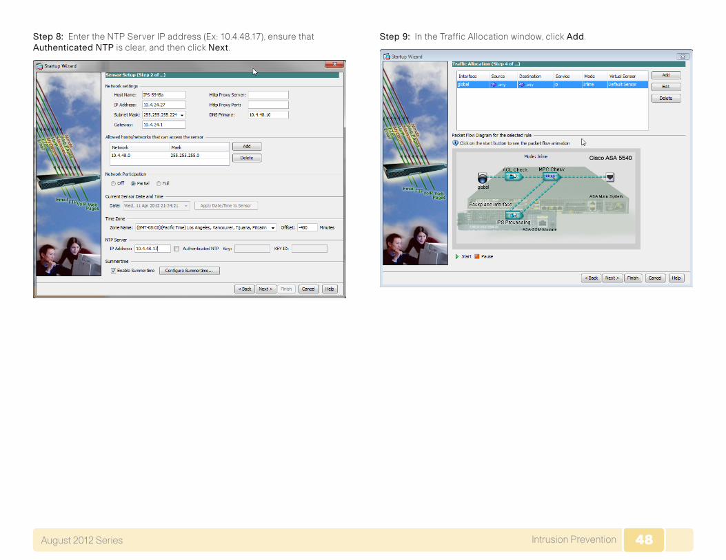
48Intrusion PreventionAugust 2012 Series 48
Step 8: Enter the NTP Server IP address (Ex: 10.4.48.17), ensure that AuthenticatedNTP is clear, and then click Next.
Step 9: In the Traffic Allocation window, click Add.

49Intrusion PreventionAugust 2012 Series 49
Step 10: In the SpecifytrafficforIPSScan dialog box, under TrafficInspectionMode, select Inline, and then click OK . If the Cisco ASA already had a default traffic allocation policy, IDM will throw a warning window that “The Service Rule Policy you are trying to create already exists.” If you receive this warning window, cancel the current window and proceed to the next step.
Step 11: Below the PacketFlowDiagramfortheselectedRule panel, click Start. This verifies the Traffic Allocation configuration. The animation illustrates a packet being sent to the IPS module and the egress interface. The animation may display a different platform that might be incorrect compared to the one that you are configuring. This will not impact the deployment and is merely a known cosmetic bug.
Step 12: At the bottom of the Startup Wizard screen, click Finish.
Step 13: When you are prompted if you want to commit your changes to the sensor, click Yes.

50Intrusion PreventionAugust 2012 Series 50
Step 14: IDM applies your changes, and replies with a Rebootrequired message. Click OK .
Step 15: Repeat the steps in Option 1 for the IPS module in the resilient Cisco ASA firewall. There is no configuration synchronization between the two devices like there is between the ASA firewalls.
Option 2. Complete the basic configuration for IPS 4x00 Se-ries Sensor appliance
Step 1: On the distribution switch to which the sensor’s monitoring ports are connected, in a command-line interface, enter the following:
interface GigabitEthernet1/0/24 description IPS4300 G0/0 no switchport no ip address no shutdown
interface GigabitEthernet2/0/24 description IPS4300 G0/1 no switchport no ip address no shutdown
monitor session 1 source interface tenGigabitEthernet1/1/1,tenGigabitEthernet2/1/1 bothmonitor session 1 destination interface GigabitEthernet1/0/24,GigabitEthernet2/0/24
Step 2: HTTPS to the management IP address on the Cisco IPS appliance (Example: https://10.4.32.171) to launch IDM.
Step 3: Navigate toConfiguration>SensorSetup>StartupWizard, and then click LaunchStartupWizard.
Step 4: Review the Startup Wizard Introduction, and then click Next.
Step 5: In SensorSetup, configure the DNS Primary server address, time zone, and NTP server address. If necessary for your time zone, select EnableSummertime.
Step 6: Verify that the AuthenticatedNTP check box is clear, and then click Next.
Step 7: On the InterfaceSummary page, click Next.

51Intrusion PreventionAugust 2012 Series 51
Step 8: On the Traffic Inspection Mode page, select Promiscuous, and then click Next.
Step 9: On the Interface Selection page, in the SelectInterface drop-down list, select GigabitEthernet0/0, and then click Next.
Step 10: On the Virtual Sensors page, review the configuration, and then click Next.
Step 11: In this step, you will configure the IPS device to automatically pull updates from Cisco.com. On the Auto Update page, select the EnableSignatureandEngineUpdates option. Provide a valid cisco.com username and password that holds entitlement to download IPS software updates. Select Daily, enter a time between 12:00 AM and 4:00 AM for the update StartTime, and then select EveryDay. Click Finish
Step 12: When asked to confirm configuration changes, click Yes.
Step 13: If a message indicates that a reboot is required, click OK.
Procedure 5 Add additional sensing interfaces
Because the appliance has multiple physical interfaces, more than one can be used to inspect traffic (either in inline or promiscuous mode). In this deployment, you will assign an additional interface on the appliance to be used for promiscuous mode as a resilient interface on the other switch in the switch stack.
Step 1: In the IPS configuration pane of ASDM (or in IDM itself), navigate to Configuration>Interfaces>Interfaces.
Step 2: Select interface GigabitEthernet0/1, and then click Enable.
Step 3: Click Apply.
Step 4: Navigate to Configuration>Policies>IPSPolicies.
Step 5: Right click vs0, and then select Edit.

52Intrusion PreventionAugust 2012 Series 52
Step 6: In the Edit Virtual Sensor dialog box, for GigabitEthernet0/1, select the Assigned box, and then click OK .
Step 7: Click Apply.
Procedure 6 Modify the inline security policy
(Optional)
If you opted to run inline mode on an IPS device, the sensor is configured to drop high-risk traffic. By default, this means that if an alert fires with a risk rating of at least 90 or if the traffic comes from an IP address with a nega-tive reputation that raises the risk rating to 90 or higher, the sensor drops the traffic. If the risk rating is raised to 100 because of the source address reputation score, then the sensor drops all traffic from that IP address.
The chances of the IPS dropping traffic that is not malicious when using a risk threshold of 90 is very low. However, if you want to adopt a more conser-vative policy, for the risk threshold, raise the value to 100.
Step 1: Navigate to Configuration>IPS>Policies>IPSPolicies(when using ASDM to configure an IPS module).
Step 2: In the Virtual Sensor panel, right-click the vs0 entry, and then select Edit.
Step 3: In the Event Action Rule work pane, click DenyPacketInlineOverride, and then click Delete.
Step 4: In the Event Action Rule work pane, Click Add.

53Intrusion PreventionAugust 2012 Series 53
Step 5: In the Add Event Action Override dialog box, in the RiskRating list, select 100-100, select DenyPacketInline, and then click OK .
Step 6: Click Apply.
Intrusion Prevention SummaryOrganizations are exposed to a large number of threats from the Internet. Cisco IPS deployed in the Internet edge of an organization or internally plays a significant role in identifying and blocking malicious traffic, and it improves the availability and security of the Internet-facing services as well as helping to identify issues and problems occurring on the LAN.

54Appendix A: Product ListAugust 2012 Series 54
Appendix A: Product List
Internet Edge
Functional Area Product Description Part Numbers Software
Firewall Cisco ASA 5545-X IPS Edition - security appliance ASA5545-IPS-K9 ASA 8.6(1)1 IPS 7.1(4) E4Cisco ASA 5525-X IPS Edition - security appliance ASA5525-IPS-K9
Cisco ASA 5515-X IPS Edition - security appliance ASA5515-IPS-K9
Cisco ASA 5512-X IPS Edition - security appliance ASA5512-IPS-K9
Cisco ASA5512-X Security Plus license ASA5512-SEC-PL
Firewall Management ASDM 6.6.114
Internet Edge LAN
Functional Area Product Description Part Numbers Software
DMZ Switch Cisco Catalyst 3750-X Series Stackable 24 10/100/1000 Ethernet ports WS-C3750X-24T-S 15.0(1)SE2
IP Base
Outside Switch Catalyst 2960S 24 GigE 4 x SFP LAN Base WS-C2960S-24TS-L 15.0(1)SE2
LAN Base
IPS
Functional Area Product Description Part Numbers Software
Distribution IDS Cisco IPS 4345 IPS-4345-K9 7.1(4)E4
Cisco IPS 4360 IPS-4360-K9
Cisco IPS 4510 IPS-4510-K9
Cisco IPS 4520 IPS-4520-K9
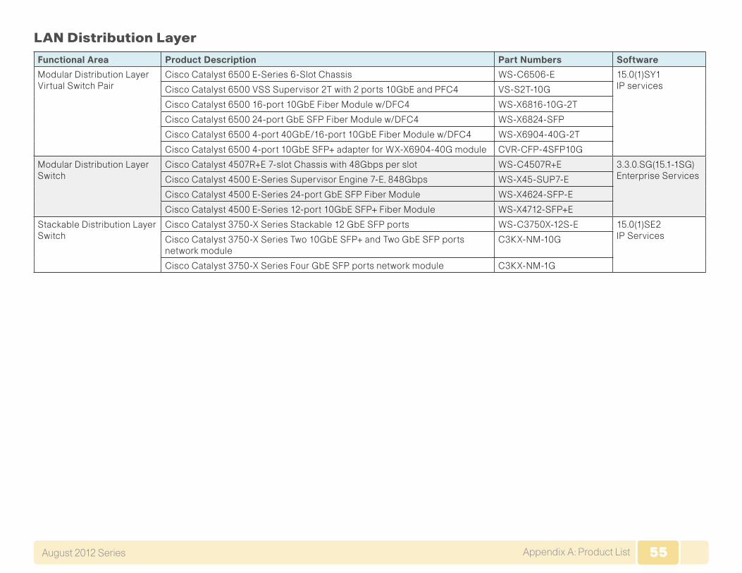
55Appendix A: Product ListAugust 2012 Series 55
LAN Distribution Layer
Functional Area Product Description Part Numbers Software
Modular Distribution Layer Virtual Switch Pair
Cisco Catalyst 6500 E-Series 6-Slot Chassis WS-C6506-E 15.0(1)SY1 IP servicesCisco Catalyst 6500 VSS Supervisor 2T with 2 ports 10GbE and PFC4 VS-S2T-10G
Cisco Catalyst 6500 16-port 10GbE Fiber Module w/DFC4 WS-X6816-10G-2T
Cisco Catalyst 6500 24-port GbE SFP Fiber Module w/DFC4 WS-X6824-SFP
Cisco Catalyst 6500 4-port 40GbE/16-port 10GbE Fiber Module w/DFC4 WS-X6904-40G-2T
Cisco Catalyst 6500 4-port 10GbE SFP+ adapter for WX-X6904-40G module CVR-CFP-4SFP10G
Modular Distribution Layer Switch
Cisco Catalyst 4507R+E 7-slot Chassis with 48Gbps per slot WS-C4507R+E 3.3.0.SG(15.1-1SG) Enterprise ServicesCisco Catalyst 4500 E-Series Supervisor Engine 7-E, 848Gbps WS-X45-SUP7-E
Cisco Catalyst 4500 E-Series 24-port GbE SFP Fiber Module WS-X4624-SFP-E
Cisco Catalyst 4500 E-Series 12-port 10GbE SFP+ Fiber Module WS-X4712-SFP+E
Stackable Distribution Layer Switch
Cisco Catalyst 3750-X Series Stackable 12 GbE SFP ports WS-C3750X-12S-E 15.0(1)SE2 IP ServicesCisco Catalyst 3750-X Series Two 10GbE SFP+ and Two GbE SFP ports
network moduleC3KX-NM-10G
Cisco Catalyst 3750-X Series Four GbE SFP ports network module C3KX-NM-1G

56Appendix B: Configuration ExampleAugust 2012 Series 56
Appendix B: Configuration Example
ASA Firewall 5545-X
!ASA Version 8.6(1)1!terminal width 511hostname IE-ASA5545Xdomain-name cisco.localenable password 2y4FIGBVVyBLau0Q encryptedpasswd 2y4FIGBVVyBLau0Q encryptednames!interface GigabitEthernet0/0 no nameif no security-level no ip address!interface GigabitEthernet0/0.300 vlan 300 nameif inside security-level 100 ip address 10.4.24.30 255.255.255.224 standby 10.4.24.29!interface GigabitEthernet0/1 no nameif no security-level no ip address!interface GigabitEthernet0/1.1116 description Web server DMZ connection on vlan 1116
vlan 1116 nameif dmz-web security-level 50 ip address 192.168.16.1 255.255.255.0 standby 192.168.16.2!interface GigabitEthernet0/1.1117 description Email Security Appliance DMZ connection on VLAN 1117 vlan 1117 nameif dmz-mail security-level 50 ip address 192.168.17.1 255.255.255.0 standby 192.168.17.2!interface GigabitEthernet0/1.1118 description DMVPN aggregation router connections on VLAN 1118 vlan 1118 nameif dmz-dmvpn security-level 75 ip address 192.168.18.1 255.255.255.0!interface GigabitEthernet0/1.1119 vlan 1119 nameif dmz-wlc security-level 50 ip address 192.168.19.1 255.255.255.0!interface GigabitEthernet0/1.1123 description Management DMZ connection on VLAN 1123 vlan 1123 nameif dmz-management security-level 50 ip address 192.168.23.1 255.255.255.0 standby 192.168.23.2!interface GigabitEthernet0/1.1128 vlan 1128 nameif dmz-guests security-level 10 ip address 192.168.28.1 255.255.252.0

57Appendix B: Configuration Example August 2012 Series 57
!interface GigabitEthernet0/2 description LAN/STATE Failover Interface!interface GigabitEthernet0/3 no nameif no security-level no ip address!interface GigabitEthernet0/3.16 description Primary Internet connection on VLAN 16 vlan 16 nameif outside-16 security-level 0 ip address 172.16.130.124 255.255.255.0 standby 172.16.130.123!interface GigabitEthernet0/3.17 description Resilient Internet connection on VLAN 17 vlan 17 nameif outside-17 security-level 0 ip address 172.17.130.124 255.255.255.0 standby 172.17.130.123!interface GigabitEthernet0/4 shutdown no nameif no security-level no ip address!interface GigabitEthernet0/5 shutdown no nameif no security-level no ip address!interface GigabitEthernet0/6 shutdown
no nameif no security-level no ip address!interface GigabitEthernet0/7 shutdown no nameif no security-level no ip address!interface Management0/0 nameif IPS-mgmt security-level 0 no ip address management-only!boot system disk0:/asa861-1-smp-k8.binftp mode passiveclock timezone PST -8clock summer-time PDT recurringdns server-group DefaultDNS domain-name cisco.localobject network dmz-networks subnet 192.168.16.0 255.255.248.0 description The Organization’s DMZ network rangeobject network Internal-network-ISPb subnet 10.4.0.0 255.254.0.0 description All Internal Networksobject network internal-network-ISPa subnet 10.4.0.0 255.254.0.0 description All Internal Networksobject network internall-network-ISPb subnet 10.4.0.0 255.254.0.0 description All Internal Networksobject network outside-webserver-ISPa host 172.16.130.100 description Webserver on ISP A

58Appendix B: Configuration Example August 2012 Series 58
object network dmz-webserver-ISPa host 192.168.16.100 description NAT the webserver in the DMZ to the outside address on ISP Aobject network dmz-webserver-ISPb host 192.168.17.100 description NAT the webserver in the DMZ to the outside address on ISP Bobject network outside-webserver-ISPb host 172.17.130.100 description Webserver on ISP Bobject network dmz-cvo-1 host 192.168.18.20object network outside-cvo-1 host 172.16.130.2object network dmz-dmvpn-1 host 192.168.18.10 description NAT the primary DMVPN hub router in the DMZ to ISP Aobject network outside-dmvpn-ISPa host 172.16.130.1 description DMVPN hub router on ISP Aobject network dmz-dmvpn-2 host 192.168.18.11 description NAT the secondary DMVPN hub router in the DMZ to ISP Bobject network outside-dmvpn-ISPb host 172.17.130.1 description DMVPN hub router on ISP Bobject network dmz-esa-ISPa host 192.168.17.25 description NAT the ESA in the DMZ to the outside address on ISP Aobject network outside-esa-ISPa host 172.16.130.25 description ESA on ISP Aobject network internal-dns host 10.4.48.10
description DNS in the internal data centerobject network internal-exchange host 10.4.48.25 description Exchange server in the internal datacenterobject network internal-ntp host 10.4.48.17 description NTP server in the internal data centerobject network 5505-pool subnet 10.4.156.0 255.255.252.0 description 5505 Teleworker Subnetobject network internal-network subnet 10.4.0.0 255.254.0.0 description The organization’s internal network rangeobject network dmz-guests-network-ISPa subnet 192.168.28.0 255.255.252.0object network guest-wlc-1 host 192.168.19.54 description Dedicated DMZ WLCobject network internal-acs host 10.4.48.15 description Internal ACSobject network internal-dhcp host 10.4.48.10 description DC DHCPobject network internal-flex-WLC7500-1 host 10.4.46.68 description Primary FlexConnect Controllerobject network internal-flex-WLC7500-2 host 10.4.46.69 description Secondary FlexConnect Controllerobject network internalWLC5508-1 host 10.4.46.64 description Primary HQ Controllerobject network internalWLC5508-2 host 10.4.46.65 description Secondary HQ Controllerobject network outside-cvo-2

59Appendix B: Configuration Example August 2012 Series 59
host 172.17.130.2 description Aggregation Router to support CVO on ISP Bobject network dmz-cvo-2 host 192.168.18.21object-group service DM_INLINE_SERVICE_1 service-object tcp destination eq ftp service-object tcp destination eq ftp-data service-object tcp destination eq tacacs service-object udp destination eq ntp service-object udp destination eq syslogobject-group service DM_INLINE_TCP_1 tcp port-object eq www port-object eq httpsobject-group service DM_INLINE_SERVICE_2 service-object esp service-object tcp destination eq 3389 service-object tcp destination eq https service-object udp destination eq 4500 service-object udp destination eq isakmpobject-group icmp-type DM_INLINE_ICMP_1 icmp-object echo icmp-object echo-replyobject-group service DM_INLINE_SERVICE_3 service-object esp service-object udp destination eq 4500 service-object udp destination eq isakmpobject-group service DM_INLINE_SERVICE_4 service-object tcp destination eq domain service-object udp destination eq domainobject-group service DM_INLINE_TCP_2 tcp port-object eq www port-object eq httpsobject-group network dmz-wlcs network-object object guest-wlc-1object-group network internal-wlcs network-object object internal-flex-WLC7500-1 network-object object internal-flex-WLC7500-2
network-object object internalWLC5508-1 network-object object internalWLC5508-2object-group service DM_INLINE_SERVICE_5 service-object tcp destination eq tacacs service-object udp destination eq 1812 service-object udp destination eq 1813object-group service DM_INLINE_SERVICE_6 service-object 97 service-object udp destination eq 16666object-group service DM_INLINE_TCP_3 tcp port-object eq ftp port-object eq ftp-dataobject-group service DM_INLINE_TCP_4 tcp port-object eq www port-object eq httpsobject-group network DM_INLINE_NETWORK_1 network-object object dmz-networks network-object object internal-networkobject-group service DM_INLINE_SERVICE_7 service-object esp service-object tcp destination eq 8000 service-object tcp destination eq https service-object udp destination eq 4500 service-object udp destination eq isakmpaccess-list global_access remark Allow Service tcp/ftp, tcp/ftp, tcp/tacacs, udp/ntp, udp/syslogsaccess-list global_access extended permit object-group DM_INLINE_SERVICE_1 192.168.23.0 255.255.255.0 object internal-network-ISPaaccess-list global_access remark Permit the DMZ to update software over HTTP/HTTPSaccess-list global_access extended permit tcp 192.168.17.0 255.255.255.0 any object-group DM_INLINE_TCP_2access-list global_access remark Permit the mail DMZ to sync with the internal NTP serveraccess-list global_access extended permit udp 192.168.17.0 255.255.255.0 object internal-ntp eq ntpaccess-list global_access remark Permit the mail DMZ to do

60Appendix B: Configuration Example August 2012 Series 60
lookups on the internal DNSaccess-list global_access extended permit object-group DM_INLINE_SERVICE_4 192.168.17.0 255.255.255.0 object internal-dnsaccess-list global_access remark Permit the mail DMZ to send SMTP to the internal exchange serveraccess-list global_access extended permit tcp 192.168.17.0 255.255.255.0 object internal-exchange eq smtpaccess-list global_access remark Permit SMTP traffic into the email DMZaccess-list global_access extended permit tcp any 192.168.17.0 255.255.255.0 eq smtpaccess-list global_access remark Allow anyone to access the webserver in the DMZaccess-list global_access extended permit tcp any 192.168.16.0 255.255.255.0 object-group DM_INLINE_TCP_1access-list global_access extended permit object-group DM_INLINE_SERVICE_2 any 192.168.18.0 255.255.255.0access-list global_access remark Allow diagnostic traffic to the DMVPN aggregation routersaccess-list global_access extended permit icmp any 192.168.18.0 255.255.255.0 object-group DM_INLINE_ICMP_1access-list global_access remark Allow traffic to the DMVPN hub routersaccess-list global_access extended permit object-group DM_INLINE_SERVICE_3 any 192.168.18.0 255.255.255.0access-list global_access remark Allow WLCs to Communicate with the Internal WLCsaccess-list global_access extended permit object-group DM_INLINE_SERVICE_6 object-group dmz-wlcs object-group internal-wlcsaccess-list global_access remark Allow WLCs to Communicate with FTP Serversaccess-list global_access extended permit tcp object-group dmz-wlcs any object-group DM_INLINE_TCP_3access-list global_access remark Allow WLCs to Communicate with the NTP Serveraccess-list global_access extended permit udp object-group dmz-wlcs object internal-ntp eq ntp
access-list global_access extended permit object-group DM_INLINE_SERVICE_5 object-group dmz-wlcs object internal-acsaccess-list global_access extended permit udp object-group dmz-wlcs object internal-dhcp eq bootpsaccess-list global_access remark Allow guest traffic to the internetaccess-list global_access extended permit ip 192.168.28.0 255.255.252.0 anyaccess-list global_access extended permit tcp 192.168.28.0 255.255.252.0 192.168.16.0 255.255.255.0 object-group DM_INLINE_TCP_4access-list global_access extended permit udp 192.168.28.0 255.255.252.0 object internal-dhcp eq bootpsaccess-list global_access extended deny ip 192.168.28.0 255.255.252.0 object-group DM_INLINE_NETWORK_1access-list global_access extended permit object-group DM_INLINE_SERVICE_7 any 192.168.18.0 255.255.255.0access-list global_access remark Deny IP traffic from the DMZ to any other networkaccess-list global_access extended deny ip object dmz-networks anyaccess-list global_access remark Deny the use of telnet from internal network to external networksaccess-list global_access extended deny tcp object internal-network-ISPa any eq telnetaccess-list global_access remark Permit IP Traffic from the internal network to external networkaccess-list global_access extended permit ip object internal-network-ISPa anyaccess-list global_mpc extended permit ip any anyaccess-list WCCP_Redirect extended permit ip any anyaccess-list global_mpc_1 extended permit ip any anyno pagerlogging enablelogging buffered informationallogging asdm informationalmtu inside 1500

61Appendix B: Configuration Example August 2012 Series 61
mtu dmz-web 1500mtu dmz-mail 1500mtu dmz-dmvpn 1500mtu dmz-wlc 1500mtu dmz-management 1500mtu dmz-guests 1500mtu outside-16 1500mtu outside-17 1500mtu IPS-mgmt 1500failoverfailover lan unit primaryfailover lan interface failover GigabitEthernet0/2failover polltime unit msec 200 holdtime msec 800failover polltime interface msec 500 holdtime 5failover key *****failover replication httpfailover link failover GigabitEthernet0/2failover interface ip failover 10.4.24.33 255.255.255.248 standby 10.4.24.34monitor-interface insidemonitor-interface dmz-webmonitor-interface dmz-mailmonitor-interface dmz-managementmonitor-interface outside-16monitor-interface outside-17icmp unreachable rate-limit 1 burst-size 1asdm image disk0:/asdm-66114.binno asdm history enablearp timeout 14400!object network Internal-network-ISPb nat (any,outside-17) dynamic interfaceobject network internal-network-ISPa nat (any,outside-16) dynamic interfaceobject network dmz-webserver-ISPa nat (any,outside-16) static outside-webserver-ISPaobject network dmz-webserver-ISPb
nat (any,outside-17) static outside-webserver-ISPbobject network dmz-cvo-1 nat (any,outside-16) static outside-cvo-1object network dmz-dmvpn-1 nat (any,any) static outside-dmvpn-ISPaobject network dmz-dmvpn-2 nat (any,any) static outside-dmvpn-ISPbobject network dmz-esa-ISPa nat (any,outside-16) static outside-esa-ISPaobject network dmz-guests-network-ISPa nat (any,outside-16) dynamic interfaceobject network dmz-cvo-2 nat (any,outside-17) static outside-cvo-2access-group global_access global!router eigrp 100 network 10.4.24.0 255.255.252.0 network 192.168.16.0 255.255.248.0 passive-interface default no passive-interface inside redistribute static!route outside-16 0.0.0.0 0.0.0.0 172.16.130.126 128 track 1route outside-17 0.0.0.0 0.0.0.0 172.17.130.126 254route outside-16 172.18.1.1 255.255.255.255 172.16.130.126 1timeout xlate 3:00:00timeout conn 1:00:00 half-closed 0:10:00 udp 0:02:00 icmp 0:00:02timeout sunrpc 0:10:00 h323 0:05:00 h225 1:00:00 mgcp 0:05:00 mgcp-pat 0:05:00timeout sip 0:30:00 sip_media 0:02:00 sip-invite 0:03:00 sip-disconnect 0:02:00timeout sip-provisional-media 0:02:00 uauth 0:05:00 absolutetimeout tcp-proxy-reassembly 0:01:00timeout floating-conn 0:00:00dynamic-access-policy-record DfltAccessPolicyaaa-server AAA-SERVER protocol tacacs+aaa-server AAA-SERVER (inside) host 10.4.48.15

62Appendix B: Configuration Example August 2012 Series 62
timeout 5 key SecretKeyuser-identity default-domain LOCALaaa authentication enable console AAA-SERVER LOCALaaa authentication ssh console AAA-SERVER LOCALaaa authentication http console AAA-SERVER LOCALaaa authentication serial console AAA-SERVER LOCALaaa authorization exec authentication-serverhttp server enablehttp 10.4.0.0 255.254.0.0 insidesnmp-server host inside 10.4.48.35 community *****no snmp-server locationno snmp-server contactsnmp-server community *****snmp-server enable traps snmp authentication linkup linkdown coldstart warmstartsla monitor 16 type echo protocol ipIcmpEcho 172.18.1.1 interface outside-16sla monitor schedule 16 life forever start-time nowcrypto ipsec ikev1 transform-set ESP-AES-256-MD5 esp-aes-256 esp-md5-hmaccrypto ipsec ikev1 transform-set ESP-DES-SHA esp-des esp-sha-hmaccrypto ipsec ikev1 transform-set ESP-3DES-SHA esp-3des esp-sha-hmaccrypto ipsec ikev1 transform-set ESP-DES-MD5 esp-des esp-md5-hmaccrypto ipsec ikev1 transform-set ESP-AES-192-MD5 esp-aes-192 esp-md5-hmaccrypto ipsec ikev1 transform-set ESP-3DES-MD5 esp-3des esp-md5-hmaccrypto ipsec ikev1 transform-set ESP-AES-256-SHA esp-aes-256 esp-sha-hmaccrypto ipsec ikev1 transform-set ESP-AES-128-SHA esp-aes esp-sha-hmaccrypto ipsec ikev1 transform-set ESP-AES-192-SHA esp-aes-192 esp-sha-hmaccrypto ipsec ikev1 transform-set ESP-AES-128-MD5 esp-aes esp-md5-hmaccrypto dynamic-map SYSTEM_DEFAULT_CRYPTO_MAP 65535 set ikev1
transform-set ESP-AES-128-SHA ESP-AES-128-MD5 ESP-AES-192-SHA ESP-AES-192-MD5 ESP-AES-256-SHA ESP-AES-256-MD5 ESP-3DES-SHA ESP-3DES-MD5 ESP-DES-SHA ESP-DES-MD5!track 1 rtr 16 reachabilitytelnet timeout 5ssh 10.4.0.0 255.254.0.0 insidessh timeout 5ssh version 2console timeout 0!tls-proxy maximum-session 1000!threat-detection basic-threatthreat-detection statistics access-listno threat-detection statistics tcp-interceptwccp 90 redirect-list WCCP_Redirectntp server 10.4.48.17webvpn csd image disk0:/csd_3.5.2008-k9.pkg anyconnect image disk0:/anyconnect-linux-3.0.07059-k9.pkg 1 anyconnect image disk0:/anyconnect-macosx-i386-3.0.07059-k9.pkg 2 anyconnect image disk0:/anyconnect-win-3.0.07059-k9.pkg 3username admin password w2Y.6Op4j7clVDk2 encrypted privilege 15!class-map global-class match access-list global_mpcclass-map inspection_default match default-inspection-trafficclass-map global-class1 match access-list global_mpc_1!!policy-map type inspect dns preset_dns_map parameters message-length maximum client auto message-length maximum 512
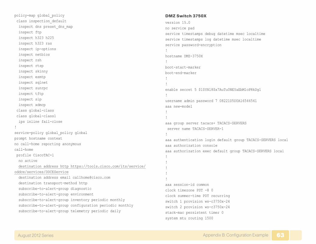
63Appendix B: Configuration Example August 2012 Series 63
policy-map global_policy class inspection_default inspect dns preset_dns_map inspect ftp inspect h323 h225 inspect h323 ras inspect ip-options inspect netbios inspect rsh inspect rtsp inspect skinny inspect esmtp inspect sqlnet inspect sunrpc inspect tftp inspect sip inspect xdmcp class global-class class global-class1 ips inline fail-close!service-policy global_policy globalprompt hostname contextno call-home reporting anonymouscall-home profile CiscoTAC-1 no active destination address http https://tools.cisco.com/its/service/oddce/services/DDCEService destination address email [email protected] destination transport-method http subscribe-to-alert-group diagnostic subscribe-to-alert-group environment subscribe-to-alert-group inventory periodic monthly subscribe-to-alert-group configuration periodic monthly subscribe-to-alert-group telemetry periodic daily
DMZ Switch 3750X
version 15.0no service padservice timestamps debug datetime msec localtimeservice timestamps log datetime msec localtimeservice password-encryption!hostname DMZ-3750X!boot-start-markerboot-end-marker!!enable secret 5 $1$YNl8$x7AuTu0NEYaEbM1oPRkDg1!username admin password 7 08221D5D0A16544541aaa new-model!!aaa group server tacacs+ TACACS-SERVERS server name TACACS-SERVER-1!aaa authentication login default group TACACS-SERVERS localaaa authorization consoleaaa authorization exec default group TACACS-SERVERS local!!!!!aaa session-id commonclock timezone PST -8 0clock summer-time PDT recurringswitch 1 provision ws-c3750x-24switch 2 provision ws-c3750x-24stack-mac persistent timer 0system mtu routing 1500

64Appendix B: Configuration Example August 2012 Series 64
!!!ip domain-name cisco.localip name-server 10.4.48.10vtp mode transparentudld enable
!!crypto pki trustpoint TP-self-signed-162045056 enrollment selfsigned subject-name cn=IOS-Self-Signed-Certificate-162045056 revocation-check none rsakeypair TP-self-signed-162045056!!crypto pki certificate chain TP-self-signed-162045056 certificate self-signed 01 3082024C 308201B5 A0030201 02020101 300D0609 2A864886 F70D0101 04050030 30312E30 2C060355 04031325 494F532D 53656C66 2D536967 6E65642D 43657274 69666963 6174652D 31363230 34353035 36301E17 0D393330 33303130 30333033 385A170D 32303031 30313030 30303030 5A303031 2E302C06 03550403 1325494F 532D5365 6C662D53 69676E65 642D4365 72746966 69636174 652D3136 32303435 30353630 819F300D 06092A86 4886F70D 01010105 0003818D 00308189 02818100 ABF9F6FB D94E88B6 1B12C51F 9056324B 97446240 F269E7E5 52BD382E D901B588 EDD64589 C3B7197C 3681571C 7C773EF2 CD07FF17 ABE2256F 4E361E67 44BDB749 DD588BC4 A350965B 08F54E1E CCEAD9E6 40110ECE 3078F46C 4DBBBD63 22C360BA
44A4A30C 5E7E7758 F28A429B D9F3A413 33E38B0E 98FB827C C96238A8 35911A25 02030100 01A37630 74300F06 03551D13 0101FF04 05300301 01FF3021 0603551D 11041A30 18821644 4D5A2D33 37353058 612E6369 73636F2E 6C6F6361 6C301F06 03551D23 04183016 80145462 690ED4BB 124834FB 3A6E746C BF14589E 2143301D 0603551D 0E041604 14546269 0ED4BB12 4834FB3A 6E746CBF 14589E21 43300D06 092A8648 86F70D01 01040500 03818100 393DB7B1 AECAFEAD A19D181C BAEFC9DA 5D8ECAA7 1512E5B6 336F0B54 5FBF2D22 8F3EAA0C CA1F3448 16F00909 6BC204BE CEEA7038 C0A3EC37 7AA24E15 903AA502 BFD5F0BC CAA44853 5B4DBD75 47F59E1A 815D3E93 45E51538 9C3BCCE2 1E3EB1EA CA5551A2 21DDF747 8147CB2C 2A446354 1A372F3F 3A68872A F2D13C6D 07EB0DE4 quit!!!!spanning-tree mode rapid-pvstspanning-tree extend system-idspanning-tree vlan 1116-1118 priority 24576!!!port-channel load-balance src-dst-ip!vlan internal allocation policy ascending!vlan 1116 name DMZ-WEB!

65Appendix B: Configuration Example August 2012 Series 65
vlan 1117!vlan 1118 name DMZ-DMVPN!vlan 1119 name WLAN_Mgmt!vlan 1123 name DMZ-MANAGEMENT!vlan 1128 name Guest_Wireless!ip ssh version 2!!!!macro name AccessEdgeQoS auto qos voip cisco-phone@macro name EgressQoS mls qos trust dscp queue-set 1 srr-queue bandwidth share 1 30 35 5 priority-queue out@!!interface Port-channel12 description DMZ-WLC-Guest switchport trunk encapsulation dot1q switchport trunk allowed vlan 1119,1128 switchport mode trunk logging event link-status!
interface FastEthernet0 no ip address shutdown!interface GigabitEthernet1/0/1 description DMZ-WLC-Guest-1 Port 1 switchport trunk encapsulation dot1q switchport trunk allowed vlan 1119,1128 switchport mode trunk logging event link-status logging event trunk-status logging event bundle-status srr-queue bandwidth share 1 30 35 5
priority-queue out mls qos trust dscp macro description EgressQoS channel-group 12 mode on!interface GigabitEthernet1/0/2 description WEBSERVER switchport access vlan 1116 switchport mode access logging event link-status srr-queue bandwidth share 1 30 35 5
priority-queue out mls qos trust dscp macro description EgressQoS spanning-tree portfast!interface GigabitEthernet1/0/3!interface GigabitEthernet1/0/4!interface GigabitEthernet1/0/5!

66Appendix B: Configuration Example August 2012 Series 66
interface GigabitEthernet1/0/6!interface GigabitEthernet1/0/7 description VPN-ASR1002-1 Gig0/0/3 switchport access vlan 1118 switchport mode access logging event link-status srr-queue bandwidth share 1 30 35 5
priority-queue out mls qos trust dscp macro description EgressQoS spanning-tree portfast!interface GigabitEthernet1/0/8!interface GigabitEthernet1/0/9 description CVOAGG-3945E-1 Gig0/3 switchport access vlan 1118 switchport mode access logging event link-status srr-queue bandwidth share 1 30 35 5
priority-queue out mls qos trust dscp macro description EgressQoS spanning-tree portfast!interface GigabitEthernet1/0/10!interface GigabitEthernet1/0/11!interface GigabitEthernet1/0/12!interface GigabitEthernet1/0/13!interface GigabitEthernet1/0/14
!interface GigabitEthernet1/0/15!interface GigabitEthernet1/0/16!interface GigabitEthernet1/0/17 description OUT-2960Sa Fas0 switchport access vlan 1123 switchport mode access spanning-tree portfast!interface GigabitEthernet1/0/18!interface GigabitEthernet1/0/19!interface GigabitEthernet1/0/20!interface GigabitEthernet1/0/21!interface GigabitEthernet1/0/22 description DMZ-ESAc370 switchport access vlan 1117 switchport mode access logging event link-status srr-queue bandwidth share 1 30 35 5
priority-queue out mls qos trust dscp macro description EgressQoS spanning-tree portfast!interface GigabitEthernet1/0/23!interface GigabitEthernet1/0/24 description IE-ASA5550a Gig0/1 switchport trunk encapsulation dot1q switchport trunk allowed vlan 1116-1119,1123,1128

67Appendix B: Configuration Example August 2012 Series 67
switchport mode trunk logging event link-status logging event trunk-status srr-queue bandwidth share 1 30 35 5
priority-queue out mls qos trust dscp macro description EgressQoS | EgressQoS | EgressQoS!interface GigabitEthernet1/1/1!interface GigabitEthernet1/1/2!interface GigabitEthernet1/1/3!interface GigabitEthernet1/1/4!interface TenGigabitEthernet1/1/1!interface TenGigabitEthernet1/1/2!interface GigabitEthernet2/0/1 description DMZ-WLC-Guest-1 Port 2 switchport trunk encapsulation dot1q switchport trunk allowed vlan 1119,1128 switchport mode trunk logging event link-status logging event trunk-status logging event bundle-status srr-queue bandwidth share 1 30 35 5
priority-queue out mls qos trust dscp macro description EgressQoS channel-group 12 mode on!interface GigabitEthernet2/0/2
description WEBSERVER switchport access vlan 1116 switchport mode access logging event link-status srr-queue bandwidth share 1 30 35 5
priority-queue out mls qos trust dscp macro description EgressQoS spanning-tree portfast!interface GigabitEthernet2/0/3!interface GigabitEthernet2/0/4!interface GigabitEthernet2/0/5!interface GigabitEthernet2/0/6!interface GigabitEthernet2/0/7 description VPN-ASR1002-1 Gig0/0/3 switchport access vlan 1118 switchport mode access logging event link-status srr-queue bandwidth share 1 30 35 5
priority-queue out mls qos trust dscp macro description EgressQoS spanning-tree portfast!interface GigabitEthernet2/0/8!interface GigabitEthernet2/0/9 description CVOAGG-3945E-2 Gig0/3 switchport access vlan 1118 switchport mode access

68Appendix B: Configuration Example August 2012 Series 68
logging event link-status srr-queue bandwidth share 1 30 35 5
priority-queue out mls qos trust dscp macro description EgressQoS spanning-tree portfast!interface GigabitEthernet2/0/10!interface GigabitEthernet2/0/11!interface GigabitEthernet2/0/12!interface GigabitEthernet2/0/13!interface GigabitEthernet2/0/14!interface GigabitEthernet2/0/15!interface GigabitEthernet2/0/16!interface GigabitEthernet2/0/17 description OUT-2960Sb Fas0 switchport access vlan 1123 switchport mode access spanning-tree portfast!interface GigabitEthernet2/0/18!interface GigabitEthernet2/0/19!interface GigabitEthernet2/0/20!interface GigabitEthernet2/0/21!interface GigabitEthernet2/0/22
!interface GigabitEthernet2/0/23!interface GigabitEthernet2/0/24 description IE-ASA5550b Gig0/1 switchport trunk encapsulation dot1q switchport trunk allowed vlan 1116-1119,1123,1128 switchport mode trunk logging event link-status logging event trunk-status srr-queue bandwidth share 1 30 35 5
priority-queue out mls qos trust dscp macro description EgressQoS | EgressQoS | EgressQoS!interface GigabitEthernet2/1/1!interface GigabitEthernet2/1/2!interface GigabitEthernet2/1/3!interface GigabitEthernet2/1/4!interface TenGigabitEthernet2/1/1!interface TenGigabitEthernet2/1/2!interface Vlan1 no ip address shutdown!interface Vlan1123 description In-band management ip address 192.168.23.5 255.255.255.0!ip default-gateway 192.168.23.1

69Appendix B: Configuration Example August 2012 Series 69
!no ip http serverip http authentication aaaip http secure-server!!ip sla enable reaction-alertslogging esm configaccess-list 55 permit 10.4.48.0 0.0.0.255!snmp-server community cisco RO 55snmp-server community cisco123 RW 55tacacs server TACACS-SERVER-1 address ipv4 10.4.48.15 key 7 15210E0F162F3F0F2D2A!!!!line con 0line vty 0 4 access-class 55 in exec-timeout 0 0 transport preferred noneline vty 5 15 access-class 55 in exec-timeout 0 0 transport preferred none!ntp server 10.4.48.17end
Outside Switch 2960S
version 15.0no service padservice timestamps debug datetime msec localtimeservice timestamps log datetime msec localtime
service password-encryption!hostname OUT-2960S!boot-start-markerboot-end-marker!enable secret 5 $1$5Ppb$vHrfB3souElPj8sw3s9i/1!username admin password 7 070C705F4D06485744aaa new-model!!aaa group server tacacs+ TACACS-SERVERS server name TACACS-SERVER-1!aaa authentication login default group TACACS-SERVERS localaaa authorization consoleaaa authorization exec default group TACACS-SERVERS local!!!!!aaa session-id commonclock timezone PST -8 0clock summer-time PDT recurringswitch 1 provision ws-c2960s-24td-lswitch 2 provision ws-c2960s-24td-lstack-mac persistent timer 0!!ip domain-name cisco.localip name-server 10.4.48.10vtp mode transparentudld enable
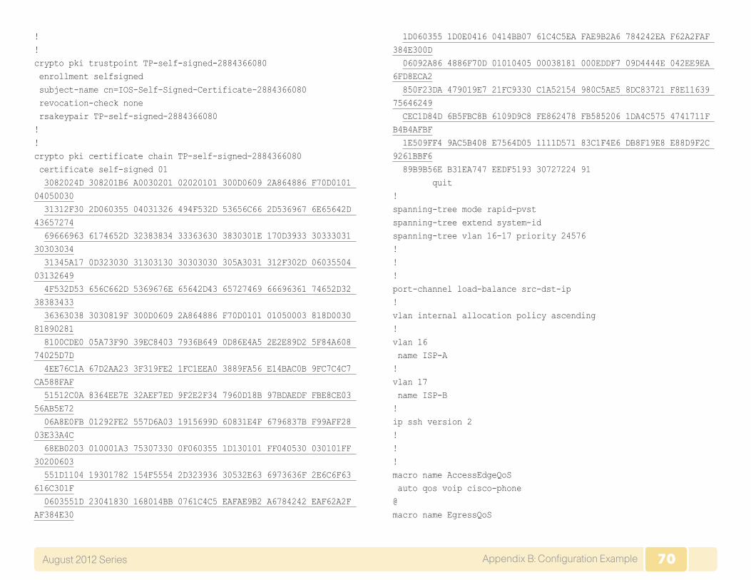
70Appendix B: Configuration Example August 2012 Series 70
!!crypto pki trustpoint TP-self-signed-2884366080 enrollment selfsigned subject-name cn=IOS-Self-Signed-Certificate-2884366080 revocation-check none rsakeypair TP-self-signed-2884366080!!crypto pki certificate chain TP-self-signed-2884366080 certificate self-signed 01 3082024D 308201B6 A0030201 02020101 300D0609 2A864886 F70D0101 04050030 31312F30 2D060355 04031326 494F532D 53656C66 2D536967 6E65642D 43657274 69666963 6174652D 32383834 33363630 3830301E 170D3933 30333031 30303034 31345A17 0D323030 31303130 30303030 305A3031 312F302D 06035504 03132649 4F532D53 656C662D 5369676E 65642D43 65727469 66696361 74652D32 38383433 36363038 3030819F 300D0609 2A864886 F70D0101 01050003 818D0030 81890281 8100CDE0 05A73F90 39EC8403 7936B649 0D86E4A5 2E2E89D2 5F84A608 74025D7D 4EE76C1A 67D2AA23 3F319FE2 1FC1EEA0 3889FA56 E14BAC0B 9FC7C4C7 CA588FAF 51512C0A 8364EE7E 32AEF7ED 9F2E2F34 7960D18B 97BDAEDF FBE8CE03 56AB5E72 06A8E0FB 01292FE2 557D6A03 1915699D 60831E4F 6796837B F99AFF28 03E33A4C 68EB0203 010001A3 75307330 0F060355 1D130101 FF040530 030101FF 30200603 551D1104 19301782 154F5554 2D323936 30532E63 6973636F 2E6C6F63 616C301F 0603551D 23041830 168014BB 0761C4C5 EAFAE9B2 A6784242 EAF62A2F AF384E30
1D060355 1D0E0416 0414BB07 61C4C5EA FAE9B2A6 784242EA F62A2FAF 384E300D 06092A86 4886F70D 01010405 00038181 000EDDF7 09D4444E 042EE9EA 6FD8ECA2 850F23DA 479019E7 21FC9330 C1A52154 980C5AE5 8DC83721 F8E11639 75646249 CEC1D84D 6B5FBC8B 6109D9C8 FE862478 FB585206 1DA4C575 4741711F B4B4AFBF 1E509FF4 9AC5B408 E7564D05 1111D571 83C1F4E6 DB8F19E8 E88D9F2C 9261BBF6 89B9B56E B31EA747 EEDF5193 30727224 91 quit!spanning-tree mode rapid-pvstspanning-tree extend system-idspanning-tree vlan 16-17 priority 24576!!!port-channel load-balance src-dst-ip!vlan internal allocation policy ascending!vlan 16 name ISP-A!vlan 17 name ISP-B!ip ssh version 2!!!macro name AccessEdgeQoS auto qos voip cisco-phone@macro name EgressQoS

71Appendix B: Configuration Example August 2012 Series 71
mls qos trust dscp queue-set 1 srr-queue bandwidth share 1 30 35 5 priority-queue out@!!interface FastEthernet0 description DMZ-3750X Gig1/0/17 ip address 192.168.23.6 255.255.255.0!interface GigabitEthernet1/0/1!interface GigabitEthernet1/0/2!interface GigabitEthernet1/0/3!interface GigabitEthernet1/0/4!interface GigabitEthernet1/0/5!interface GigabitEthernet1/0/6!interface GigabitEthernet1/0/7!interface GigabitEthernet1/0/8!interface GigabitEthernet1/0/9!interface GigabitEthernet1/0/10!interface GigabitEthernet1/0/11!interface GigabitEthernet1/0/12!interface GigabitEthernet1/0/13!
interface GigabitEthernet1/0/14!interface GigabitEthernet1/0/15!interface GigabitEthernet1/0/16!interface GigabitEthernet1/0/17!interface GigabitEthernet1/0/18!interface GigabitEthernet1/0/19!interface GigabitEthernet1/0/20 description VPN-ASA5525a Gig0/3 switchport trunk allowed vlan 16,17 switchport mode trunk logging event link-status logging event trunk-status srr-queue bandwidth share 1 30 35 5
priority-queue out mls qos trust dscp macro description EgressQoS spanning-tree portfast trunk!interface GigabitEthernet1/0/21!interface GigabitEthernet1/0/22!interface GigabitEthernet1/0/23 description ISP-A switchport access vlan 16 switchport mode access duplex full spanning-tree portfast!interface GigabitEthernet1/0/24

72Appendix B: Configuration Example August 2012 Series 72
description IE-ASA5540a Gig0/3 switchport trunk allowed vlan 16,17 switchport mode trunk logging event link-status logging event trunk-status!interface GigabitEthernet1/0/25!interface GigabitEthernet1/0/26!interface TenGigabitEthernet1/0/1!interface TenGigabitEthernet1/0/2!interface GigabitEthernet2/0/1!interface GigabitEthernet2/0/2!interface GigabitEthernet2/0/3!interface GigabitEthernet2/0/4!interface GigabitEthernet2/0/5!interface GigabitEthernet2/0/6!interface GigabitEthernet2/0/7!interface GigabitEthernet2/0/8!interface GigabitEthernet2/0/9!interface GigabitEthernet2/0/10!interface GigabitEthernet2/0/11!interface GigabitEthernet2/0/12
!interface GigabitEthernet2/0/13!interface GigabitEthernet2/0/14!interface GigabitEthernet2/0/15!interface GigabitEthernet2/0/16!interface GigabitEthernet2/0/17!interface GigabitEthernet2/0/18!interface GigabitEthernet2/0/19!interface GigabitEthernet2/0/20 description VPN-ASA5525b Gig0/3 switchport trunk allowed vlan 16,17 switchport mode trunk logging event link-status logging event trunk-status srr-queue bandwidth share 1 30 35 5
priority-queue out mls qos trust dscp macro description EgressQoS spanning-tree portfast trunk!interface GigabitEthernet2/0/21!interface GigabitEthernet2/0/22!interface GigabitEthernet2/0/23 description ISP-B switchport access vlan 17 switchport mode access spanning-tree portfast

73Appendix B: Configuration Example August 2012 Series 73
!interface GigabitEthernet2/0/24 description IE-ASA5540b Gig0/3 switchport trunk allowed vlan 16,17 switchport mode trunk logging event link-status logging event trunk-status!interface GigabitEthernet2/0/25!interface GigabitEthernet2/0/26!interface TenGigabitEthernet2/0/1!interface TenGigabitEthernet2/0/2!interface Vlan1 no ip address shutdown!ip default-gateway 192.168.23.1no ip http serverip http authentication aaaip http secure-server!logging esm configaccess-list 55 permit 10.4.48.0 0.0.0.255snmp-server community cisco RO 55snmp-server community cisco123 RW 55tacacs server TACACS-SERVER-1 address ipv4 10.4.48.15 key 7 00371605165E1F2D0A38!!!line con 0line vty 0 4
access-class 55 in transport preferred none transport input sshline vty 5 15 access-class 55 in transport preferred none transport input ssh!ntp source FastEthernet0ntp server 10.4.48.17end

74Appendix C: Changes August 2012 Series 74
Appendix C: Changes
This appendix summarizes the changes to this guide since the previous Cisco SBA series.
• In The Firewall section, we added additional information about how to deploy the outside and DMZ switches. In the previous series, this information was not complete.
• In Intrusion Prevention, we added an IPS appliance in promiscuous mode for internal inspection. We also rewrote the technical overview to better explain the differences between IPS modules and appliances and between deploying a device in inline or promiscuous mode.

SMART BUSINESS ARCHITECTURE
ALL DESIGNS, SPECIFICATIONS, STATEMENTS, INFORMATION, AND RECOMMENDATIONS (COLLECTIVELY, “DESIGNS”) IN THIS MANUAL ARE PRESENTED “AS IS,” WITH ALL FAULTS. CISCO AND ITS SUPPLiERS DISCLAIM ALL WARRANTIES, INCLUDING, WITH-OUT LIMITATION, THE WARRANTY OF MERCHANTABILITY, FITNESS FOR A PARTICULAR PURPOSE AND NONINFRINGEMENT OR ARISING FROM A COURSE OF DEALING, USAGE, OR TRADE PRACTICE. IN NO EVENT SHALL CISCO OR ITS SUPPLIERS BE LIABLE FOR ANY INDIRECT, SPECIAL, CONSEQUENTIAL, OR INCIDENTAL DAMAGES, INCLUDING, WITHOUT LIMITATION, LOST PROFITS OR LOSS OR DAMAGE TO DATA ARISING OUT OF THE USE OR INABILITY TO USE THE DESIGNS, EVEN IF CISCO OR ITS SUPPLIERS HAVE BEEN ADVISED OF THE POSSIBILITY OF SUCH DAMAGES. THE DESIGNS ARE SUBJECT TO CHANGE WITHOUT NOTICE. USERS ARE SOLELY RESPONSIBLE FOR THEIR APPLICATION OF THE DESIGNS. THE DESIGNS DO NOT CONSTITUTE THE TECHNICAL OR OTHER PROFESSIONAL ADVICE OF CISCO, ITS SUPPLIERS OR PARTNERS. USERS SHOULD CONSULT THEIR OWN TECHNICAL ADVISORS BEFORE IMPLEMENTING THE DESIGNS. RESULTS MAY VARY DEPENDING ON FACTORS NOT TESTED BY CISCO.
Any Internet Protocol (IP) addresses used in this document are not intended to be actual addresses. Any examples, command display output, and figures included in the document are shown for illustrative purposes only. Any use of actual IP addresses in illustrative content is unintentional and coincidental.
© 2012 Cisco Systems, Inc. All rights reserved.
Click here to provide feedback to Cisco SBA.
Feedback
Americas HeadquartersCisco Systems, Inc.San Jose, CA
Asia Pacific HeadquartersCisco Systems (USA) Pte. Ltd.Singapore
Europe HeadquartersCisco Systems International BV Amsterdam,The Netherlands
Cisco has more than 200 offices worldwide. Addresses, phone numbers, and fax numbers are listed on the Cisco Website at www.cisco.com/go/offices.
Cisco and the Cisco logo are trademarks or registered trademarks of Cisco and/or its affiliates in the U.S. and other countries. To view a list of Cisco trademarks, go to this URL: www.cisco.com/go/trademarks. Third-party trademarks mentioned are the property of their respective owners. The use of the word partner does not imply a partnership relationship between Cisco and any other company. (1110R)
B-0000180-1 8/12