Finite element analysis of riveted joints in old steel ... · Paper Number 06 Finite element...
11
Paper Number 06 Finite element analysis of riveted joints in old steel buildings in NZ M. Naderi Department of Civil and Environmental Engineering. University of Auckland. 2008 NZSEE Conference ABSTRACT: In the early 20th century, steel frame buildings were built to different standards from those used in modern construction. Riveted, built-up members were used instead of rolled sections, with joints and members encased in concrete for fire protection. These early steel buildings were designed based upon observations of past building performance rather than through detailed calculations and predictions of structural behaviour. The walls were infill masonry and floors were typically reinforced concrete. The strength and stiffness of the semi-rigid connections and masonry infill as well as the effect of floor slabs integral with their supporting beams are not well documented. Although riveted stiffened seat angle connections are not designed to resist moments, they can develop a considerable moment capacity and exhibit a relatively ductile hysteretic behaviour which could be beneficially considered when evaluating frames built of these connections and subjected to small and moderate earthquakes. Structural engineers have found it challenging to make realistic predictions of the seismic performance of these buildings, many which are quite prestigious, in full service and often enjoying heritage protection. Examples include Auckland’s Britomart Station and Guardian Trust Building, and Wellington’s Tower Corporation, Prudential Assurance and Hope-Gibbons Buildings. To predict the complicated behaviour of riveted connections, 3D nonlinear finite element models of a sample clip-angle connection taken from drawings of the now-demolished Jean-Batten building in Auckland and a sample T-stub connection taken from drawings of the Hope-Gibbons building have been generated using the ABAQUS finite element software package. The joint models were used to investigate load-displacement, failure mode and energy dissipation under axial loads, shear loads, and combined axial loads plus shear loads. 1 INTRODUCTION for much of the first half of the 20 th century lateral loads on buildings were under-estimated by design standards and the resulting gravity load-dominated structures tended to be constructed using steel frames using what would be considered today as semi-rigid or flexible types of connections. Fortunately the concrete encasement that was often used for fire protection purposes probably bestowed additional strength and stiffness on the joints and members of these older buildings that make up a small but significant part of our built environment. Assessing the seismic adequacy of such buildings is the ultimate aim of the research reported in this paper. Accurate assessment of the strength and hysteretic capabilities of these riveted and encased joints may
Transcript of Finite element analysis of riveted joints in old steel ... · Paper Number 06 Finite element...

Paper Number 06
Finite element analysis of riveted joints in old steel buildings in NZ
M. Naderi Department of Civil and Environmental Engineering. University of Auckland.
2008 NZSEE Conference
ABSTRACT: In the early 20th century, steel frame buildings were built to different standards from those used in modern construction. Riveted, built-up members were used instead of rolled sections, with joints and members encased in concrete for fire protection.
These early steel buildings were designed based upon observations of past building performance rather than through detailed calculations and predictions of structural behaviour. The walls were infill masonry and floors were typically reinforced concrete. The strength and stiffness of the semi-rigid connections and masonry infill as well as the effect of floor slabs integral with their supporting beams are not well documented.
Although riveted stiffened seat angle connections are not designed to resist moments, they can develop a considerable moment capacity and exhibit a relatively ductile hysteretic behaviour which could be beneficially considered when evaluating frames built of these connections and subjected to small and moderate earthquakes. Structural engineers have found it challenging to make realistic predictions of the seismic performance of these buildings, many which are quite prestigious, in full service and often enjoying heritage protection. Examples include Auckland’s Britomart Station and Guardian Trust Building, and Wellington’s Tower Corporation, Prudential Assurance and Hope-Gibbons Buildings.
To predict the complicated behaviour of riveted connections, 3D nonlinear finite element models of a sample clip-angle connection taken from drawings of the now-demolished Jean-Batten building in Auckland and a sample T-stub connection taken from drawings of the Hope-Gibbons building have been generated using the ABAQUS finite element software package. The joint models were used to investigate load-displacement, failure mode and energy dissipation under axial loads, shear loads, and combined axial loads plus shear loads.
1 INTRODUCTION
for much of the first half of the 20th century lateral loads on buildings were under-estimated by design standards and the resulting gravity load-dominated structures tended to be constructed using steel frames using what would be considered today as semi-rigid or flexible types of connections. Fortunately the concrete encasement that was often used for fire protection purposes probably bestowed additional strength and stiffness on the joints and members of these older buildings that make up a small but significant part of our built environment. Assessing the seismic adequacy of such buildings is the ultimate aim of the research reported in this paper.
Accurate assessment of the strength and hysteretic capabilities of these riveted and encased joints may

2
show that they make a significant contribution to the seismic performance of a building. This could significantly lessen the extent and intrusiveness of any retrofitting required, particularly in less active seismic zones. Furthermore, there is a need for localized seismic retrofit strategies that could be implemented with minimum disturbance to the occupants, preferably without the need to remove the concrete encasement to expose the connections.
Although many studies (summarised in this paper) have experimentally and analytically investigated the seismic adequacy of some types of riveted connections, there exists little literature on the cyclic behaviour and seismic retrofit of riveted connections.
2 HISTORY OF RIVETED JOINTS
Prior to the 1920s, steel frames commonly were constructed as complex built-up members with gusset plates and built-up connections.
The built-up members were employed because labour costs were low, and the built-up design allowed savings in material and versatility in construction, since a wide range of members could be constructed with a small number of shapes and sizes. This permitted shipping of large quantities of a few steel sizes, and avoided shipping delays when changes were required at the job site. This was important because there was no standardisation of shapes across different steel producers and rolling mills.
For instance, built-up members of Auckland’s harbour bridge have been shipped from London to Auckland and members and connections were riveted on site.
In riveted structures, the entire steel frame was normally encased in concrete for fire protection. Few if any of these structures were designed for seismic loading, only wind load was considered prior 1930. In some older buildings, even wind load received minimal consideration. These buildings invariably included many stiff, strong un-reinforced masonry walls and partitions. Structural engineers relied upon these walls and partitions to help resist lateral loads, but there is little evidence of calculation of the stiffness and resistance provided by these walls.
The Home Insurance building, a 9-story structure erected in Chicago in 1885 and later expanded to 11 stories in 1891, is generally credited with being the first skyscraper, beginning the era of tall structures in which the principal (or only) load-bearing system was a steel frame.
Changes in steel frames began to evolve around 1920. Labour costs for the built-up elements were increasing at this time and standard hot rolled shapes for beams and columns became the normal practice. The AISC Specification and Manual (AISC- 1928) was first developed in this period. These rolled shapes commonly were connected with riveted angles and T-sections as illustrated in Figures 1 and 2, and members and the connections were still encased in concrete for fire protection. These connections became standard and were designed with relatively simple calculations for the next 20 to 30 years. Unreinforced masonry curtain walls and partitions were still used, and the combined effect of the added strength and stiffness provided by these walls and the composite action due to the encasement supplied a major portion of the structural stiffness and resistance to lateral loads.
Seismic design forces were considered in these structures(1930-1955), but the seismic design forces were simplified and often much smaller than those used today. These early structures were highly redundant in that every beam-column connection.
So lateral resistance came from a moment-resistant connection plus a large but uncalculated stiffness provided by non-structural elements such as architectural masonry walls and the concrete encasement.
Paper Number 06
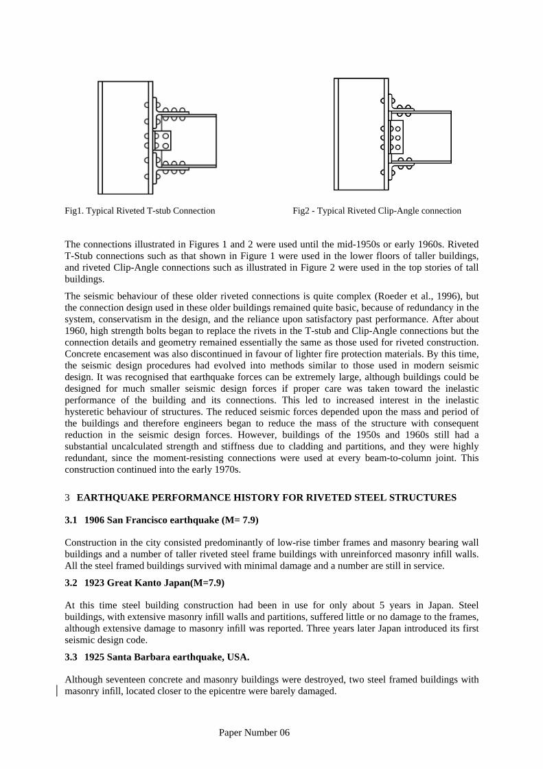
Fig1. Typical Riveted T-stub Connection Fig2 - Typical Riveted Clip-Angle connection
The connections illustrated in Figures 1 and 2 were used until the mid-1950s or early 1960s. Riveted T-Stub connections such as that shown in Figure 1 were used in the lower floors of taller buildings, and riveted Clip-Angle connections such as illustrated in Figure 2 were used in the top stories of tall buildings.
The seismic behaviour of these older riveted connections is quite complex (Roeder et al., 1996), but the connection design used in these older buildings remained quite basic, because of redundancy in the system, conservatism in the design, and the reliance upon satisfactory past performance. After about 1960, high strength bolts began to replace the rivets in the T-stub and Clip-Angle connections but the connection details and geometry remained essentially the same as those used for riveted construction. Concrete encasement was also discontinued in favour of lighter fire protection materials. By this time, the seismic design procedures had evolved into methods similar to those used in modern seismic design. It was recognised that earthquake forces can be extremely large, although buildings could be designed for much smaller seismic design forces if proper care was taken toward the inelastic performance of the building and its connections. This led to increased interest in the inelastic hysteretic behaviour of structures. The reduced seismic forces depended upon the mass and period of the buildings and therefore engineers began to reduce the mass of the structure with consequent reduction in the seismic design forces. However, buildings of the 1950s and 1960s still had a substantial uncalculated strength and stiffness due to cladding and partitions, and they were highly redundant, since the moment-resisting connections were used at every beam-to-column joint. This construction continued into the early 1970s.
3 EARTHQUAKE PERFORMANCE HISTORY FOR RIVETED STEEL STRUCTURES
3.1 1906 San Francisco earthquake (M= 7.9)
Construction in the city consisted predominantly of low-rise timber frames and masonry bearing wall buildings and a number of taller riveted steel frame buildings with unreinforced masonry infill walls. All the steel framed buildings survived with minimal damage and a number are still in service.
3.2 1923 Great Kanto Japan(M=7.9)
At this time steel building construction had been in use for only about 5 years in Japan. Steel buildings, with extensive masonry infill walls and partitions, suffered little or no damage to the frames, although extensive damage to masonry infill was reported. Three years later Japan introduced its first seismic design code.
3.3 1925 Santa Barbara earthquake, USA.
Although seventeen concrete and masonry buildings were destroyed, two steel framed buildings with masonry infill, located closer to the epicentre were barely damaged.

4
4 PAST EXPERIMENTAL RESULTS
A number of past tests (Roeder et al., 1994; Hechtmann and Johnston, 1947; Batho, et al., 1934, 1936, and 1938) on T-stub connections are available. Most of the data deals with riveted connections and monotonic behaviour, but some tests examine cyclic inelastic behaviour and high-strength bolts. Many of the riveted connections tested were concrete encased following the common practice of encasing for fire protection reasons. The concrete encasement may increase the strength and stiffness of the connection by as much as 30-50%, but the general behaviour, including modes of failure and deformation limits, was unchanged.
The cyclic moment-rotation behaviour of T-stub connections is pinched as shown in Fig 3. Figure 5 is the moment-rotation curve for a specimen with tight fitting mild steel bolts which were designed to simulate rivets. Shear yielding of the bolts connecting the beam flange to the stem of the T-section was the yield mechanism, and shear fracture of the bolts was the failure mode for this test. It can be seen that the connection had limited rotational capacity with this behaviour. Yielding of clip angles in riveted connections generally contributed more to joint ductility than rivet yielding.
Fig 3- Moment-Rotation curve for a T-stub joints with mild steel bolt
5 MATERIAL
5.1 Mechanical Properties of Structural Steel
For the ABAQUS model currently being developed the material is modelled as non-linear elasto-plastic and fracture is assumed to occur when plastic strain exceeds a pre-set limit.
5.2 Fasteners
In USA, rivets are made of ASTM A502-9. This type of material was formerly designated as ASTM -A141. They are available in three grades.
• Grade 1 for standard structural application
• Grade 2 is for use with high-strength carbon and high strength low-alloy structural steel.
• Grade 3 is similar to grade 2 but has enhanced corrosion resistance.
ASTM does not specify any strength or hardness requirement for rivets in the driven state.
(Kulak 1987) suggested for rivet material ultimate tensile strength of 60 ksi (414 N/mm2) for grade 1
and 80 ksi (552 N/mm2) for grade 2,3.
(Kulak 1987) suggested for rivet material shear strength of 45-60 ksi for grade 1 and 65-80 ksi for grade 2,3.

5
A reasonable lower bound estimate of the rivet tensile capacity is 60 ksi for A502 grade 1 which must increase 10-20% in driven condition.
6 HERITAGE STEEL STRUCTURES WITH RIVETED JOINTS IN NZ
The drawings of a number of heritage steel buildings in Auckland and Wellington have been examined and used to define the geometric parameters of the two FE joint models reported herein. Model A (clip angle type) is based on Auckland’s former Jean Batten building and model B (T-stub) on Wellington’s Hope-Gibbons building. A few details of some of these buildings are given below.
6.1 Former CPO/Britomart Transport Centre, 12 Queen St
Completed in 1912 it served as Auckland’s Chief Post office until 1992. Subsequently it has been redeveloped as the entrance to the Britomart Transport Centre. One of the riveted joints of its steel frame has been exposed as a feature of interest in the basement., fig. 4.
6.2 Guardian Trust building, Auckland central, 105 Queen Street
Erected during the First World War for the New Zealand Insurance Company (NZI), this was one of Auckland’s first high-rise buildings and replaced an earlier three-storey NZI building and features a projecting clock from this earlier building.
Fig 4. Glass-enclosed riveted joint at Britomart Transport Centre Fig 5. Guardian Trust building
6.3 Jean Batten State Building
The building established in 1941 as post office named in honor of New Zealand’s most famous woman aviator. Jean Batten became an overnight international celebrity when she smashed the women’s record for a solo flight from England to Australia in 1934. Jean Batten State Building , located on Queen street, Auckland central now almost demolished to replaced of BNZ building.
6.4 St James Theatre, Auckland central
In this building Construction is a mixture of reinforced concrete frames, unreinforced masonry, riveted structural steel supporting the suspended balconies, and riveted steel roof trusses.
St James Theatre was Completed in 1927 and recently with no more activities due to retrofitting process.

6
6.5 Government Life Insurance (now Tower Corporation) building, Wellington
50–64 Customhouse Quay (1930) After the 1931 Napier earthquake the old masonry building was thought unsafe and it was pulled down. The present building was designed by Government Architect, John Mair, and completed in 1936. Government Life became a corporation in 1983, and in 1989 it became Tower Corporation.
6.6 Hope Gibbons building, Wellington
A 8 story building located in Wellington which completed in 1925 and now use for both commercial and residential purpose.
6.7. Prudential Assurance Building, 332–340 Lambton Quay This outstanding art deco building was designed in 1933 by Hennessey and Hennessey, Australia, and completed the following year. It was one of the first buildings in Wellington to have a steel-framed structure incorporated in its design, the result of a new earthquake code introduced in New Zealand after the disastrous Napier earthquake of 1931.
Fig 6. Hope Gibbons building, Wellington Fig 7. Prudential Assurance Building , Wellington
7 FINITE ELEMENT ANALYSIS
A number of previous finite element analyses of riveted joints have been reported in the literature (Roeder et al 1994, for example). These have varied in complexity, but seldom incorporated detailed modelling of contact between rivet shaft and hole or rivet ends and clamped plates. They have also incorporated a wide range of material models, failure surfaces, geometric nonlinearity and imposed load or displacement sequences. Models containing fine detail tended to cause high demand for computing resources.
The present study included two exterior beam-column joint models, A (clip angle, based on Jean Batten building, Auckland)) and B (T-stub, based on Hope Gibbons building, Wellington). The columns above and below the joint carried no axial load and were fixed at mid-storey level. Monotonic axial and shear loading was applied at the free end of the beam. The model included detailed modelling of rivet contact using reduced 20 node quadratic brick elements and an isotropic elasto-plastic material model with a Mises yield surface, rate independent plasticity, kinematic hardening and a fracture criterion based on limiting plastic strain.
Element type C3D20R (Reduced 20-node quadratic brick) was used. Although this element type provided high accuracy and prevented any unpredicted errors such as shear locking, it increased time and cost of running significantly compared with simpler alternatives.

7
Fig 8. Clip Angle joint (model A) Fig 9. T-Stub joint (model B)
The “contact pair, finite sliding” option was chosen and also “surface behaviour, no separation” options were used to simulate the full contact condition between rivet shank and hole surface.
7.1 Geometric parameters of models
Geometrical properties of connection models for FE analysis are listed in table 1 accompanying with column and beam sections.
Table 1. Geometric parameters of models
FE Model Column Section (in)
Beam Section (in)
Top Angle Section (in)
Bottom Angle Section (in)
Length of Beam
(cm)
Length of Column
(cm)
Rivet (in)
Clip- Angle (Model A)
BSB 120
(10*8)
BSB138 (20*7.5)
BSUA115 (6*3*.5)
BSUA115 (6*3*.5)
50 100 12* 3/4
T-Stub (Model B)
BSB133 (16*8)
BSB124 (12*8)
(8*12*.75) (8*12*.75) 50 100 20* 3/4
Model A was based on drawings of Auckland’s Jean Batten building and Model B on drawings of the Hope-Gibbons building in Wellington.
8 RESULT
8.1 Failure Mode
8.1.1 Clip Angle Connection (Model A)
8.1.1.1 Tension Load
Model A consisted of 12 A502 rivets (3/4 in) installed in standard holes - a very common joint among old steel buildings.
In general yield mechanisms may include tensile yielding of rivets, shear yielding of the panel zone, flexural yielding of the beam, tensile yielding of the stem of the angle, and local flexural yielding of the flange of the angle. Figure 18 illustrates the yield mechanism of model A under tension load leading to ultimate failure when involving fracture of the rivets connecting top angle and column flange. Figure 11 illustrates the development of plastic strain in the most critical part of model A under tension load, where the middle section of the rivets is subjected to a plastic strain reaching the pre-set limit (which means moving beyond the strain hardening region and into the necking area), meanwhile other parts of the joint remain elastic.
As can be seen, under tension load, ultimate fracture develops from the middle of the rivets towards

8
each end. This failure mode is not desirable as it has been observed (Roeader at al 1994) that tensile yield of rivets generally leads to less joint ductility and rotational capacity than flexural yield of beam flange or clip angles.
Fig. 11 appears to show large joint deformations, but this is due to the large scale factor used – in fact the large plastic strains in the rivets occur at relatively small deformation levels. At peak monotonic load a big distortion of the joint zone leads to undesirable displacement for the whole assembly.
8.1.1.2 Shear and Moment Load
Figure 10 illustrates failure mode of model A under shear load where the most important aspects include flexural yielding in the stem of the top angle, shear yielding of rivets and local buckling of column and beam flanges. In this case, final failure occurred in the stem of the bottom angle because of high plastic strain associated with flexural yielding. Flexural yielding of the angle stems results in greater ductility and rotational capacity than shear yield of rivets as occurred under tension loading.
Fig 10. Ultimate failure(flexural yielding) in the stem of top angle Fig 11. Shear yielding of rivets under tension load
A typical connection force-displacement curve for model A under shear load is shown in Fig. 12.
Fig 12 shows three different response zones with an initial elastic response with high initial stiffness followed by initiation of yielding with local plastic deformation of clip angle plus limited slippage of rivets and a final section with fairly constant stiffness as nonlinear geometric effects counteract continuing plastic deformation.
0
100
200
300
400
500
600
700
0 0.05 0.1 0.15 0.2 0.25 0.3 0.35 0.4 0.45 0.5
Displacement (cm)
Forc
e (K
N)
fig12. Typical Force-displacement curve for angle under tension load
Comparing force-displacement curve for both connections showed more stiffness and also less storey drift for T-Stub connections.

9
8.1.2. T-Stub Connection (Model B)
8.1.2.1 Tension Load
The failure modes of the T-stub connection are more complex than clip-angle connection. Fracture of the stem of the T-section and the beam flange, fracture of the tensile rivets, fracture of the flange of the T-section due to plastic deformation, elongation of the rivet holes and failure due to local buckling and excessive deformation of the beam and column are all possible failure modes. Several of these failure modes are influenced by the uncertainty in the tensile forces in the rivets due to prying action.
The evolution of the connection response under tension-load can be described as follows:
(1) Initially the connections responded linearly with a high initial stiffness.
(2) At higher load amplitudes the frictional resistance of the A502 rivet groups was overcome, and the T-Stub slipped with little resistance.
(3) As the connection rotation increased, the rivet shanks eventually started to bear against the sides of the holes and the stiffness increased again.
Under tension load, tension failure of rivets is known to be likely to be the governing failure mode.
The distribution of plastic strain in model B is shown in Fig. 13 and shows the plastic strain spreading from the middle of the rivet shank towards the ends.
The relationship between axial stress and strain for a critical rivet during non linear analysis is shown in Fig. 15.
Fig 15 displays four regions - an elastic region, then a period of yield initiation followed by a long period of plastic flow and strain hardening, finally terminated by necking and fracture at a high plastic strain of about 0.18.
8.1.2.2 Shear and Moment Load
The behaviour of this sub-assemblage under shear loading was strongly influenced by both the response of the T-Stub stem connection and by the shear yielding of the rivets between column flange and T-Stub angle, see Fig. 14.
Fig 14 . Von-Misses stress for T-stub joint under shear load Fig13. Cross-Section of T-Stub model showing plastic strain
A combination of shear and flexural failure of rivets was the main failure mode due to shear load as can be seen in Figure 16 which shows the distribution of plastic strain.

10
0
500
1000
1500
2000
2500
3000
3500
4000
0 0.02 0.04 0.06 0.08 0.1 0.12 0.14 0.16 0.18 0.2
Plastic Strain
Stre
ss
Fig15. Axial Stress-Strain curve of a rivet under tension load. Fig 16. Plastic strain in joint under shear load at rupture point
For the initial small amplitude forces, the connections responded linearly with a high stiffness. As the force increased, the forces transferred through the T-stub shear planes exceeded the shear yield capacity of the rivets. This resulted in large local deformations of the rivet shank at the shear plane, primarily as a consequence of plastic flow of the soft rivet material in the bearing area. The rivet shape at the shear plane became nearly oblong, leading to gaps between the rivet and the holes between T-stub and column flange.
8.2 Energy Dissipation
The T-Stub connection exhibited larger energy dissipation than the clip-angle connection which means it can be expected to provide more ductility than the T-Stub.
9 CONCLUSIONS
From this analytical study of the nonlinear elso-plastic behaviour of existing riveted Clip-Angle and T-Stub connections, it can be concluded that:
9.1 Although both riveted joints do not considered resisting moments connections, they can develop a considerable moment capacity which could be beneficially considered when evaluating frames built of these connections and subjected to small and moderate earthquakes.
9.2 To have a better seismic behaviour of riveted joints like higher ductility and moment capacity , it is important to understand the possible failure modes to prevent undesirable failure modes like shear yielding of rivets.
9.3 The riveted T-stub connection is significantly stiffer and stronger than the riveted clip-angle connection which means T-Stub connections provide less storey drift for building.
9.4 The response of either T-Stub or Clip-Angle connection was controlled mostly by the shear-tensile deformation of the rivet groups located between column flange and angle and shear-tensile failure was mostly main cause of joint fracture.
9.5 The T-Stub connection did exhibit larger energy dissipation and can develop more ductility than Clip-Angle connection for both shear and tensile loading.
9.6 The relatively stiff PR connections such as T-stub connection have potential to develop a resistance exceeding the plastic capacity of the connected members.

11
ACKNOWLEDGEMENTS The authors wish to acknowledge the financial support of The New Zealand Foundation for Research, Science and Technology (FRST).
10 REFERENCES
[1] Sarraf M, Bruneau M. Cyclic testing of existing and retrofitted riveted stiffened seat angle connections. ASCE Structural Journal 1996;122(7):762–75.
[2] Roeder CW, Leon RT, Preece FR. Strength, stiffness and ductility of older steel structures under seismic loading. Report No. SGEM 94-4.
[3] Roeder CW, Knechtel B, Thomas E, Vaneaton A, Leon RT, Preece FR. Seismic behaviour of older steel structures. ASCE Structural Journal 1996;122(4):365–73.
[4] FEMA355D, State of the Art Report on Connection Performance, September, 2000.
[5] Bisson MA, Bruneau M. Experimental study on cyclic behaviour of riveted stiffened seat angle connections with concrete encasement, Engineering Structure 2000; 22 1086-1096.
[6] Applied Technology Council. ATC-24 guidelines for cyclic seismic testing of components of steel structures. Redwood City, California: Applied Technology Council, 1992.
[7] Kulak GL, Fisher JW, Struik JHA. Guide to design criteria for bolted and riveted joints. 2nd edition. New York: John Wiley and Sons, 1987.