FINGERPRINT IDENTIFICATION AND VERIFICATION USING …
89
i ST. MARY’S UNIVERSITY SCHOOL OF GRADUATE STUDIES ================================================= FINGERPRINT IDENTIFICATION AND VERIFICATION USING MINUTIAE EXTRACTION FOR CRIME INVESTIGATION BY; KIBROM DESTA ADVISOR; Hafte Abera(Msc) A Thesis Submitted to the School of Graduate Studies of St. Mary’s University in Partial Fulfillment For The Degree of Master of Science in Computer Science June , 2018
Transcript of FINGERPRINT IDENTIFICATION AND VERIFICATION USING …

i
ST. MARY’S UNIVERSITY
SCHOOL OF GRADUATE STUDIES
=================================================
FINGERPRINT IDENTIFICATION AND VERIFICATION
USING MINUTIAE EXTRACTION FOR CRIME
INVESTIGATION
BY; KIBROM DESTA
ADVISOR; Hafte Abera(Msc)
A Thesis Submitted to the School of Graduate Studies of
St. Mary’s University in Partial Fulfillment For
The Degree of Master of Science in
Computer Science
June , 2018
ii
ACCEPTANCE
FINGERPRINT IDENTIFICATION AND VERIFICATION
USING MINUTIAE EXTRACTION FOR CRIME
INVESTIGATION
By
KIBROM DESTA
Accepted by the Faculty of Informatics, St. Mary’s University, in partial
fulfillment of the requirements for the degree of Master of Science in Computer
Science
Thesis Examination Committee:
_____________________________________________________
Internal Examiner
_____________________________________________________
External Examiner
_____________________________________________________
Dean, Faculty of Informatics
June 2018

iii
DECLARATION
I, the undersigned, declare that this thesis work is my original work, has not been
presented for a degree in this or any other universities, and all sources of materials used
for the thesis work have been duly acknowledged.
Kibrom Desta Tesfu
______________________________________
Full Name of Student
_________________________________
Signature
Addis Ababa
Ethiopia
This thesis has been submitted for examination with my approval as advisor.
Ato. Hafte Abera __________________________________
Full Name of Advisor
________________________________
Signature
Addis Ababa
Ethiopia
June 2018

iv
ACKNOWLEDGMENTS
First and foremost my special thanks go to the almighty God for his kindness, blessings and
forgiveness of my everyday sins with the courage and endurance to successfully complete this
research work.
Next to this I would like to express my deepest gratitude to my advisor Ato.Hafte Abera for his
motivate and constructive guidance right from the moments of problem formulation to the
completion of the work. Many thanks and appreciations go to him for the discussions with him
always made me think that things are possible.
I would also like to thank my brothers Anteneh Masresha, and Biruk Werku for sharing valuable
ideas and encouragement. Without their support, I may not have the opportunity to finish my
thesis.
I would also like to extend my appreciation and thanks to the Ethiopian Federal Police
commission AFIS employers for supplying samples of fingerprint images for different database.
I am also very thankful to my instructors and all staff members of the School of Information
Science for their contribution for the success of my study.
Finally, I would like to thank my father, mother and all the rest of my families, friends and peers
who, in one or the other way brought me up to a success in my academic endeavor.

v
Table of Contents 1.
Acknowledgments.......................................................................................................................... iv
Acronyms and Abbreviations ....................................................................................................... xii
Abstract ........................................................................................................................................ xiii
CHAPTER ONE ............................................................................................................................. 1
Introduction ..................................................................................................................................... 1
1.1. Background .......................................................................................................................... 2
1.2. Motivation ............................................................................................................................ 3
1.3. Statement of the problem ..................................................................................................... 4
1.3.1. Research Questions........................................................................................................ 6
1.4. Objective of the Research .................................................................................................... 6
1.4.1. General objective ........................................................................................................... 6
1.4.2. Specific objectives ......................................................................................................... 6
1.5. Methodology of the Study .................................................................................................... 7
1.5.1. Literature review ............................................................................................................ 7
1.5.2. Dataset collection .......................................................................................................... 7
1.5.3 Development Techniques and Tools .............................................................................. 8
1.5.4 Fingerprint Performance Evaluations ............................................................................. 8
1.6. Scope of the Research .......................................................................................................... 9
1.7. Limitation of the Research ................................................................................................... 9
1.8. Significance of the Research ................................................................................................ 9
1.9. Application of Results ........................................................................................................ 10
1.10. Organization of the Thesis ............................................................................................... 10

vi
Chapter Two.................................................................................................................................. 12
Literature Review.......................................................................................................................... 12
2.1. Overview ............................................................................................................................ 12
2.2. History of Fingerprint ........................................................................................................ 14
2.2.1. Types of Fingerprints Patterns ..................................................................................... 15
2.3. Digital image processing .................................................................................................... 17
2.3.1. Low-level processes .................................................................................................... 18
2.3.2. Mid-level processes ..................................................................................................... 18
2.3.3. High-level processes .................................................................................................... 19
2.4. Fundamental Steps of Digital Image Processing................................................................ 19
2.4.1. Image Acquisition........................................................................................................ 19
2.4.2. Image Pre-processing .................................................................................................. 21
2.4.3. Fingerprint Image Enhancement ................................................................................. 21
2.4.4 Binarization .................................................................................................................. 22
2.4.5 Thinning........................................................................................................................ 22
2.5. Minutiae Extraction ............................................................................................................ 23
2.6. Fingerprint image segmentation ......................................................................................... 24
2.7. Minutiae Matching ............................................................................................................. 25
2.7.1. Correlation-based approaches ...................................................................................... 25
2.7.2 Minutiae-based approaches .......................................................................................... 26
2.8. Fingerprint Representation ................................................................................................. 27
2.8.1. Image-based representation ......................................................................................... 27
2.8.2. Global Ridge Pattern representation ............................................................................ 28
2.8.3. Local Ridge Detail representation ............................................................................... 28
2.8.4. Intra-ridge Detail representation .................................................................................. 28

vii
2.9. Review of Related Works .................................................................................................. 29
CHAPTER THREE ...................................................................................................................... 34
Design and Implementation of Fingerprint Identification and verification .................................. 34
3.1. Overview ............................................................................................................................ 34
3.2. Fingerprint recognition ....................................................................................................... 35
3.2.1. Fingerprint verification process ................................................................................... 35
3.2.2. Fingerprint identification process ................................................................................ 35
3.3. System Architecture ........................................................................................................... 36
3.4. Fingerprint Image Preprocessing ....................................................................................... 38
3.4.1 Cropping and Resizing Finger Print Images ................................................................. 38
3.4.2. Fingerprint Image Enhancement ................................................................................. 39
3.4.3. Fingerprint Binarization .............................................................................................. 41
3.4.4. Fingerprint Ridge Thinning ......................................................................................... 42
3.5. Minutia Extraction.............................................................................................................. 43
3.5.1. Minutia Marking .......................................................................................................... 46
3.6. Minutia Post-processing ..................................................................................................... 47
3.6.1. False Minutia Removal ................................................................................................ 47
3.6.2. Euclidean Distance ...................................................................................................... 47
3.6.3. ROI .............................................................................................................................. 49
3.7. Fingerprint Matching.......................................................................................................... 50
3.7.1. Minutiae Match............................................................................................................ 50
3.7.2. Alignment Stage .......................................................................................................... 52
3.7.3. Match Stage ................................................................................................................. 54
3.7.4. Decision making matching .......................................................................................... 54
CHAPTER FOUR ......................................................................................................................... 55

viii
Experimentation ............................................................................................................................ 55
4.1. Dataset ................................................................................................................................ 55
4.2. Experimental Setup ............................................................................................................ 56
4.2.1 Experiment: Determining Threshold for Similarity Score ........................................... 56
4.2.2. Experimental Result and Analysis ............................................................................... 56
CHAPTER FIVE .......................................................................................................................... 58
Conclusion and Recommendation ................................................................................................ 58
5.1. Conclusion .......................................................................................................................... 58
5.2. Recommendation ................................................................................................................ 60
6. References ................................................................................................................................. 61
Appendix ....................................................................................................................................... 65
ix
List of Figures
Figure 3-1: The proposed approach for fingerprint identification and verification ...................... 37
Figure 3-2: Original input image .................................................................................................. 38
Figure 3-3: Resized image ............................................................................................................ 39
Figure 3-4: FFT Enhanced Image ................................................................................................. 40
Figure 3-5: Binarized image ......................................................................................................... 41
Figure 3-6: Thinned image ............................................................................................................ 43
Figure 3-7: Minutia marking image .............................................................................................. 46
Figure 3-8: False Minutia Removal .............................................................................................. 48
Figure 3-9: segmented image ........................................................................................................ 50

x
List of Tables
Table 2-1: Related Work Review ................................................................................................. 32
Table 4-1: Experimental Result .................................................................................................... 57

xi
List of Equations
Equation 3-1: FFT equation to enhance a specific block ............................................................. 39
Equation 3-2: Cross Numbering ................................................................................................... 45
Equation 3-3: Euclidean Distance ................................................................................................. 48
Equation 3-4: Similarity Score...................................................................................................... 53
Equation 3-5: Rigid Transformation ............................................................................................. 53
Equation 3-6: Transformation Matrix ........................................................................................... 53

xii
ACRONYMS AND ABBREVIATIONS
AFIS Automatic Fingerprint Identification System
CN Crossing Number
EER Equal Error Rate
FFT Fast Fourier Transform
FP Finger Print
FPCIB Federal Police Crime Investigation Bureau
FMR False Match Rate
FNMR False Non Match Rate
HE Histogram Equalization
ROI Region of Interest
TE Template Extraction
TM Transform Matrix
xiii
Abstract
Crime has a negative impact on the socio- economic development of the world. Due to this
Ethiopian federal police and other law enforcement agencies have the objective of effectively
controlling crimes. These law enforcement agencies require assistance of scientific evidences
during crime investigation. Fingerprint, as one of such scientific evidence, has an important
scientific aid in the investigation of crime and administration of justice.
Ensuring reliable minutiae extraction is one of the most important issues in automatic fingerprint
identification and verification. The fingerprint identification and verification method is divided
into four stages. The first is acquisition stage which captures the fingerprint image. The second is
pre-processing stage which attempt for enhancement and binarization, of fingerprint images. In
this work a novel method for fingerprint identification and verification is considered using a Fast
Fourier Transform (FFT) to enhance the fingerprint image. The third stage is feature extraction,
in this study the minutiae extractor methods are used to extract ridge ending and ridge
bifurcation from thinned fingerprint image. The fourth stage is matching for fingerprint
identification and verification. This is done by matching two minutiae points using minutiae
matcher method in which similarity and distance measure are applied.
We have used 300 fingerprint images for each of the 30 persons (ten fingerprints each) that are
with criminals and innocent. From those images 85% of the dataset is used for training and 15%
of the data set is used for testing. The experimental result demonstrates that the proposed
technique is effective for the identification and verification of persons. The new developed
method can successfully identify and verify the examined fingerprint images with an accuracy of
90.1%.
Keywords: Minutiae point, Feature extraction, Fingerprint identification, Fingerprint
verification
1
CHAPTER ONE
Introduction
The word biometrics is derived from the Greek words bios (meaning life) and metron (meaning
measurement); biometric identifiers are measurements from living human body. Perhaps all
biometric identifiers are a combination of anatomical and behavioral characteristics and they
should not be exclusively classified into either anatomical or behavioral characteristics. For
example, fingerprints are anatomical in nature but the usage of the input device (e.g., how a user
presents a finger to the fingerprint scanner) depends on the person’s behavior. Thus, the input to
the recognition engine is a combination of anatomical and behavioral characteristics [1].
Automated fingerprint recognition systems have been deployed in a wide variety of application
domains ranging from forensics to mobile phones [1]. Designing algorithms for extracting
salient features from fingerprints and matching them is still a challenging and important pattern
recognition problem. This is due to the large intra-class variability and large inter-class similarity
in fingerprint patterns [1].
Fingerprint recognition system may be either a verification system or an identification system
depending on the context of the application. A verification system authenticates a person’s
identity by comparing the captured fingerprint with her/his previously enrolled fingerprint
reference template. An identification system recognizes an individual by searching the entire
enrolment template database for a match. The fingerprint feature extraction and matching
algorithms are usually quite similar for both fingerprint verification and identification problems
[1].
2
1.1. Background
The Ethiopian ancient traditional techniques of investigating criminals had laid down the basis
for the present criminal investigation techniques. Among the techniques, ―Afersatta‖- which is to
mean communal inquiry- and ―Lebashay,‖ were the most commonly and widely exercised
methods [19]. In fact, there had been other methods of crime investigation like tenkway
(sorcerer) and arradazebagna.
Afersatta (or sometimes called Auchachign) is a method of crime investigation and identification
of long standing and was used almost up to the end of the first half of the 20th
century. The other
system of traditional crime detection or crime identification known as ―Lebashay,‖ was also in
use. The process of identification by Lebashay, in which a young boy would be given a powerful
drug and let lose in the neighborhood, the unfortunate owner of the house where the boy
collapsed would be declared the culprit or after took the drug and he cached a person that person
was criminal [19].
When we come back to the history of fingerprint in Ethiopia, historians tell us that Ethiopians
have a very long history related to the use of fingerprints which dates back to the ancient times
though it is a big and difficult task to exactly tell specific time.
The modern fingerprint in Ethiopia established in 1936 E.C in Addis Ababa by the help of
British officers [19]. And in 1969 E.C the forensic science laboratory was restricted under the
crime investigation with six laboratories, and fingerprint laboratory is one of the six and the
oldest found in to the Police Force Central Bureau [19].
Now, the Ethiopian federal police crime investigation forensic directorate which is found in
Addis Ababa around Black Lion Hospital. At the time of its foundation, it had the objective of
3
giving forensic investigation services like identification of fingerprints for criminals, to all
Ethiopian people and throughout the country. The investigation services were supposed given to
all regional police forces.
The forensic investigation directorate has 9 investigation divisions, such as cybercrime
investigation, fingerprint identification investigation, document investigation, explosive crime
investigation and weapon investigation.
Among the different forensic investigation divisions, this study focuses on fingerprint
identification investigation division, with the aim of designing automatic fingerprint
identification system (AFIS).
1.2. Motivation
Nowadays, fingerprint recognition is used by millions of people in their daily life in order to
verify and identify a person in commercial applications, in work places or libraries, access
control at amusement parks or zoos, to unlock notebooks, tablets or mobile phones, most
fingerprint recognition system use features from minutiae for comparing fingerprints [3]. Typical
processing steps prior to minutiae extraction are fingerprint segmentation, orientation field
estimation and image enhancement. The segmentation step divides an image into foreground, the
Region of Interest (ROI), and background [3].
In Ethiopia context, fingerprint identification is used by different government and private
organizations, especially in the Ethiopian federal police commission. However, the software and
tools have been designed and maintained by foreign investors. Besides, the minutia extracted
from the fingerprint is highly dependent on the quality of the input fingerprint image. The images
are scanned after the person puts his fingerprint on the paper.

4
In the process of minutiae extraction from the fingerprint, the noise that arises due to low quality
is a problem to extract actual features from the minutiae. This research the application of well
suited enhancement algorithm on the input image for attaining better result from low quality
images.
Therefore, to get good results in fingerprint recognition system with scanned images, the low
quality image needs to be improved using different algorithms and reduce false result errors. As
a result crime investigation and civil organizations provide good service for customers.
1.3. Statement of the problem
Biometric systems are the best way among the best methods of uniquely identifying individual
persons even in identical twins. The most popular one biometric is fingerprint identification. The
main problem of fingerprint verification and identification systems is rooted from two types of
errors. The first is the false match, where a match occurs between images from two different
fingers. The second is false non-match, where an image from the same finger does not match due
to different reasons. Fingerprint matching remains as a challenge in pattern recognition due to
the difficulty in matching fingerprints affected by one or several factors [1]. Most of the
shortcomings in the accuracy of an automatic fingerprint identification system can be attributed
to the acquisition process, some of them are:
Inconsistent contact human finger is not a rigid object and if projection of the finger surface
onto the image acquisition surface is not precisely controlled, different impressions of a finger
can be created by various transformations.
Irreproducible contacts sometimes accidents, manual work, burn etc. inflict injuries to the
finger and can permanently damage the ridge structure of the finger.

5
Small overlapping area and nonlinear distortion the improper placement of user’s finger on
the sensor or stamp area in unsupervised condition may result in a limited overlapping area
between two impressions of the same finger. Given that a very small number of minutiae in the
overlapping area, it is difficult to determine if two fingerprints are from the same finger.
Non-uniform contact in an ideal case, only the ridge lines makes contact with the sensing
surface and valleys remain untouched to make a prefect impression of the fingerprint. However,
the dryness of the skin, shallow or worn-out ridges (due to aging or genetics), skin disease,
sweat, dirt, and humidity in the air all confound the situation, resulting in a non-ideal contact
situation. In the case of inked fingerprints, an additional factor may include inappropriate inking
of the finger and may results in noisy, low contrast images, which leads to either spurious or
missing minutiae.
Most of the organizations in our country use manual data entry to optical scanner system which
leads to encounter problems such as:
i. Generating a case filing number for each of the cases has been cumbersome because it is
not easy to trace the file number of the last recorded case and this has led to duplication
cases file numbers.
ii. Accuracy about dates of filling various components of the cases is not readily available
making referencing them very cumbersome.
iii. Making references to existing criminal cases is difficult because of the manual mode of
documentation.
iv. Delay in accessing information in paper files, paper files are sometimes damaged by
water, pest or fire outbreak and can easily be altered by an unauthorized user.
v. Hesitation to identify and detect criminals timely

6
vi. Therefore, this research work aims to analyze the recognition rate under various
fingerprint images and conditions in term of accuracy with percentage of
fingerprint matching.
1.3.1. Research Questions
1. Is it possible to design effective and efficient fingerprint enhancement algorithm?
2. To what degree the performance of the fingerprint image identification and verification
system is improved by introducing effective combined feature extraction and partial
matching approaches?
3. What flaws are identified and what possible remedies are recommended to come up with
an applicable system?
1.4. Objective of the Research
1.4.1. General objective
The general objective of this study is to design fingerprint identification and verification
techniques for crime investigation.
1.4.2. Specific objectives
To achieve the general objective those study formulates the following specific objectives
To review related works regarding fingerprint identification and verification mechanisms.
To select suitable methods for fingerprint image processing segmentation and feature
extraction identification of fingerprint recognition.
Optimize the distance between adjacent minutiae using heuristic rules to minimize the
number of false or spurious minutiae
To outline evidences and their specific characteristics and describe the general features of
fingerprint
7
To develop prototype using MATLAB.
To test and evaluate the selected method.
1.5. Methodology of the Study
Methodology is an approach which involves data collection, analysis and interpretation that
show how a researcher achieves the objectives and answers the research questions. Hence, in
order to achieve the specific and general objectives of the study and answer the research
questions, the following methods are used.
1.5.1. Literature review
Several previously proposed related literatures (from books, articles and conference proceedings)
are briefly reviewed in order to have detail understanding on the present research. As
continuation of two previous attempts [4, 44], different techniques and tools which are relevant
for the current research are analyzed, modified and adopted from their works. Since the current
research is designing fingerprint image identification and verification method for fingerprint
image.
1.5.2. Dataset collection
For this study, fingerprint images AFIS of criminals have collected from federal police crime
investigation fingerprint identification datacenter. A total of 300 fingerprint images was collected
from 30 persons (ten fingerprints each) .These collected image was converted to digital image
using an Epson flatbed scanner. The resolution of the scanned images is within the acceptable
values (500dpi), while the size is about 200×200 and is in JPG format.
8
1.5.3 Development Techniques and Tools
Template extraction in this process the individuals fingerprint image is scanned and marked with
minutiae points and store in to the database along with the passenger personal details.
For image preprocessing and analysis of fingerprint images, MATLAB for windows was used.
This tool has a great capability on array based data processing. Thus, for the purposes of pre-
processing like enhancement and segmentation of an image and creating the MATLAB will be
used.
For minutiae extraction minutiae are essentially terminations and bifurcations of the ridge lines.
A cross numbering Toolbox provided by MATLAB will be used. And fingerprint-matching
algorithms minutiae-based used alignment and transform methods depend on MATLAB math
work.
1.5.4 Fingerprint Performance Evaluations
Fingerprint verification system commits two types of errors, such as: two different fingers
considered as the same fingers (called false match) and two same fingers considered as two
different fingers (called false non-match). These two types of errors are also often denoted as
false acceptance and false rejection.
1. False Match Rate (FMR) or there is a mistake when accepting fingerprint template that should
not belong to the same fingerprint.
2. False Non-Match Rate (FNMR) or there is a mistake when rejecting fingerprint template that
should belong to the same fingerprint.
9
1.6. Scope of the Research
The scope of the research is forensic investigation that is more or less searching for the truth in
criminal cases. Simply start with a client who knows or suspects that a criminal offence has been
committed and finish by proving that someone is either guilty or innocent.
1.7. Limitation of the Research
This research, as part of fingerprint biometric technology has many benefits. It also have some
limiting factors. These devices capture not only an image of the finger, but also a picture of the
dirt, greases, and contamination found on the finger. Therefore, in certain areas, there are
chances of being rejected by the system if for example a worker has a mark or some other
contaminants on his finger. The matching algorithm best suits for comparing two images with
small misalignments; if the orientation of the fingerprints is different the possibility of getting
low matching score for similar fingerprint images is larger.
1.8. Significance of the Research
Fingerprint analysis has been used to identify suspects and solve crimes for more than 100 years,
and it remains an extremely valuable tool for law enforcement. One of the most important uses
for fingerprints is to help investigators link one crime scene to another involving the same person.
Fingerprint identification also helps investigators to track a criminal’s record, their previous
arrests and convictions, to aid in sentencing, probation, parole and pardoning decisions.
In addition, fingerprints can link a perpetrator to other unsolved crimes if investigators have
reason to compare them, or if prints from an unsolved crime turn up as a match during a
database search. Sometimes these unknown prints linking multiple crimes can help investigators
piece together enough information to zero in on the culprit.

10
Fingerprints are especially importantin the criminal justice realm. Investigators and analysts can
compare unknown prints collected from a crime scene to the known prints of victims, witnesses
and potential suspects to assist in criminal cases. Fingerprints are used by the criminal justice
system to verify a convicted offender’s identity and track their previous arrests and convictions,
criminal tendencies, known associates and other useful information. Officers of the court can
also use these records to help make decisions regarding a criminal’s sentence, probation, parole
or pardon.
1.9. Application of Results
The development of such a system has a great advantage for the crime investigation. Some of the
application areas of this work are:
Early stage fingerprint image identification and verification: since we are using a real
time criminals and innocent people’s identification and verification system the
development of this application will increase the effectiveness of criminal’s controlling
mechanism. This application also helps the civilian like immigration, airport and national
ID to take an effective use this approach by identifying the persons.
Minimize the needs of experts: since we are developing an automatic identification and
verification system that uses a technique vision to identify suspects, it will eliminate the
needs of experts in that area.
1.10. Organization of the Thesis
This thesis consists of 6 chapters including these chapters. Chapter one introduced the overview,
research objectives, motivation, statement of the problem, scope of the research and
methodology. Chapter two highlights about the literature review which was used as a guide

11
throughout the research. Chapter three discusses related work of the research. Chapter three
explains about the system design of the research about the fingerprint image preprocessing which
deals with image enhancement, minutiae extraction and fingerprint image post processing which
deals with removing false minutiae and about the minutiae matching which deals with
identification whose fingerprint is it. Chapter four presents about the experimental result of
simulation. Chapter five explains conclusion and recommendation of the research.

12
Chapter Two
Literature Review
2.1. Overview
Finger impression matching is most widely used method for individual identification and
verification. So a number of researches had been done in the area of feature extraction and
matching. Every time the accuracy of matching is a factor to impression .In this review we are
discussing about minutia extraction method of finger impression matching. Following are some
of the paper from where we got an idea about the matching and minutiae extraction algorithm.
Fingerprint identification and verification system is one of the biometrics methods that are very
reliable identification methods for every person. Due to the rapid devolvement on technology,
fingerprint recognition had successfully implemented to some applications for use in verification
and identification. Reason of implementation of fingerprint recognition in fingerprint
identification and verification system is because of it can obtain easily, unalterable and unique.
The research paper main objectives had concerned about to apply the biometrics to fingerprint
identification and verification system forensic science to support criminal investigation and in
biometric systems, such as civilian and commercial identification devices to make the user’s
more easily and effectively.
Fingerprints have been used for over a century and are one of many forms of biometrics [3] to
identify an individual and to verify their identity [4]. Fingerprint identification is commonly
employed in forensic science to support criminal investigations and in biometric systems, such as
civilian and commercial identification devices. Hence, there is a widespread use of fingerprints
[1]. Fingerprint recognition is being widely applied for personal identification with the purpose

13
of high degree of security [32] by matching processes between two human fingerprints.
However, some fingerprint images captured in variant applications are poor in quality, which
corrupted the accuracy of fingerprint recognition [33]. With identity fraud in our society reaching
unprecedented proportions and an increasing emphasis on the emerging personal automatic
identification applications, biometrics based verification, especially fingerprint-based
identification, is receiving a lot of attention [34]. Fingerprint matching techniques can be
classified into three types [3].Correlation-based matching, minutiae-based matching and non-
minutiae. Minutiae-based matching is the most popular and most widely used technique, being
the basis of the fingerprint comparison [35]. The widely used minutiae-based representation does
not utilize a significant component of the rich discriminatory information available in the
fingerprints. Local ridge structures cannot be completely characterized by minutiae. Further,
minutiae-based matching has difficulty in quickly matching two fingerprint images containing
different numbers of unregistered minutiae points [36]. Algorithm is designed to recognize
fingerprint images using a Gabor filter to capture both local and global details in a fingerprint
with eight different directions.

14
2.2. History of Fingerprint
There is archaeological evidence that fingerprints as a form of identification have been used at
least since 7000 to 6000 BC by the ancient Assyrians and Chinese [47]. Clay pottery from these
times sometimes contains fingerprint impressions placed to mark the potter. Chinese documents
bore a clay seal marked by the thumbprint of the originator. Bricks used in houses in the ancient
city of Jericho were sometimes imprinted by pairs of thumbprints of the bricklayer. However,
though fingerprint individuality was recognized, there is no evidence this was used on a
universal basis in any of these societies. In the mid-1800's scientific studies were begun that
would established two critical characteristics of fingerprints that are true still to this day: no two
fingerprints from different fingers have been found to have the same ridge pattern, and
fingerprint ridge patterns are unchanging throughout life[47].
These studies led to the use of fingerprints for criminal identification, first in Argentina in 1896,
then at Scotland Yard in 1901, and to other countries in the early 1900's.Computer processing of
fingerprints began in the early 1960s with the introduction of computer hardware that could
reasonably process these images. Since then, automated fingerprint identification systems (AFIS)
have been deployed widely among law enforcement agencies throughout the world. In the 1980s,
innovations in two technology areas, personal computers and optical scanners, enabled the tools
to make fingerprint capture practical in non-criminal applications such as for ID-card programs.
Now, in the late 1990s, the introduction of inexpensive fingerprint capture devices and the
development of fast, reliable matching algorithms have set the stage for the expansion of
fingerprint matching to personal use. Why include a history of fingerprints in this chapter? This
history of use is one that other types of biometric do not come close to. Thus there is the
15
experience of a century of forensic use and hundreds of millions of fingerprint matches by which
we can say with some authority that fingerprints are unique and their use in matching is
extremely reliable [39].
Forensic scientists have used fingerprints in criminal investigations as a means of identification
for centuries. Fingerprint identification is one of the most important criminal investigation tools
due to two features: their persistence and their uniqueness [47]. A person’s fingerprints do not
change over time. The friction ridges which create fingerprints are formed while inside the
womb and grow proportionally as the baby grows. Permanent scarring is the only way a
fingerprint can change. In addition, fingerprints are unique to an individual. Even identical twins
have different fingerprints.
2.2.1. Types of Fingerprints Patterns
Fingerprints are classified by arch, loop, or whorl [47]. All three of these types of fingerprints
have more specified types. There are eight general prints in total: the Plain Arch, the Tented
Arch, the Central Pocket Loop, the Ulnar Loop, the Radial Loop, the Plain Whorl, the accidental
Whorl, and the Double Loop Whorl [47].
Arches A fingerprint pattern in which the ridges pattern originates from one side of the pattern
and leaves from other side Arches can be broken into two sub-groups: Plain Arch: - This has a
gentle rise. While tented arch; This has a steeper rise than plain arches.
Loops a fingerprint pattern in which the ridge pattern flows inward and returns in the direction of
the origin. Loops can be divided into two groups: Radial loops: - These flow downward and
toward the radius (or the thumb side). Ulnar loops: - These flows toward the ulnar (or the little
finger side). The ulnar loop is more common.

16
Whorls ridges from circularly around a central point on finger. Whorls have a circular pattern
and have at least two deltas and a core.
A fingerprint is the feature pattern of one finger. Strong evidences shows that each fingerprint is
unique[6]. Each person has his own fingerprints with the permanent uniqueness. So fingerprints
have been used for identification and forensic investigation for a long time [6].
A fingerprint is an impression of the friction ridges of all part of the finger. A friction ridge is a
raised portion of the epidermis on the palmer (palm) or digits (fingers and toes) or plantar (sole)
skin, consisting of one or more connected ridge units of friction ridge skin [7]. Among all the
biometric techniques, fingerprint-based identification is the oldest method which has been
successfully used in numerous applications. Everyone is known to have unique, immutable
fingerprints [7].
A fingerprint is made of a series of ridges and furrows on the surface of the finger [8]. The
uniqueness of a fingerprint can be determined by the pattern of ridges and furrows as well as the
minutiae points. Minutiae points are local ridge characteristics that occur at either a ridge
bifurcation or a ridge ending [8]. The number and locations of the minutiae vary from finger to
finger in any particular person, and from person to person for any particular finger (for example,
the thumb on the left hand) [9]. When a set of finger images is obtained from an individual, the
number of minutiae is recorded for each finger. The precise locations of the minutiae are also
recorded, in the form of numerical coordinates, for each finger. The result is a function that can
be entered and stored in a computer database. A computer can rapidly compare this function with
that of anyone else in the world whose finger image has been scanned [9].

17
2.3. Digital image processing
Image Processing is processing of images using mathematical operations by using any form of
signal processing for which the input is an image, a series of images, or a video, such as a
photograph or video frame; the output of image processing may be either an image or a set of
characteristics or parameters related to the image. Most image-processing techniques involve
treating the image as a two-dimensional signal and applying standard signal-processing
techniques to it. Images are also processed as three-dimensional signals where the third-
dimension being time or the z-axis. Image processing usually refers to digital image processing,
but optical and analog image processing are also possible [38].
The acquisition of images (producing the input image in the first place) is referred to as imaging.
In modern sciences and technologies, images also gain much broader scopes due to the ever
growing importance of scientific visualization (of often large-scale complex
scientific/experimental data). Examples include microarray data in genetic research, or real-time
multi-asset portfolio trading in finance. Image analysis is the extraction of meaningful
information from images; mainly from digital images by means of digital image processing
techniques [38]. Image analysis tasks can be as simple as reading bar coded tags or as
sophisticated as identifying a person from their face. Computers are indispensable for the
analysis of large amounts of data, for tasks that require complex computation, or for the
extraction of quantitative information. On the other hand, the human visual cortex is an excellent
image analysis apparatus, especially for extracting higher-level information, and for many
applications-including medicine, security, and remote sensing - human analysts still cannot be
replaced by computers. For this reason, many important image analysis tools such as edge
detectors and neural networks are inspired by human visual perception models.

18
There are no clear-cut boundaries in the continuum from image processing at one end to
computer vision at the other. However, one useful paradigm is to consider three types of
computerized processes in this continuum: low- level processes, mid- level processes, and high-
level processes [38].
2.3.1. Low-level processes
Low-level processes involve primitive operations such as image preprocessing to reduce noise,
contrast enhancement, and image sharpening. A low-level process is characterized by the fact
that both its inputs and outputs are images.
2.3.2. Mid-level processes
Mid-level processing on images involves tasks such as segmentation (partitioning an image into
regions or objects), description of those objects to reduce them to a form suitable for computer
processing, and classification (recognition) of individual objects. A mid-level process is
characterized by the fact that its inputs generally are images, but its outputs are attributes
extracted from those images (e.g., edges, contours, and the identity of individual objects).

19
2.3.3. High-level processes
Higher-level processing involves ―making sense‖ of an ensemble of recognized objects, as in
image analysis, and, at the far end of the continuum, performing the cognitive functions normally
associated with vision.
2.4. Fundamental Steps of Digital Image Processing
There are some fundamental steps in digital image processing [41].Such as image acquisition,
image enhancement, image binarization, image thinning, image extraction, image segmentation
and image matching.
2.4.1. Image Acquisition
This is the first step or process of the fundamental steps of digital image processing. Image
acquisition could be as simple as being given an image that is already in digital form. Generally,
the image acquisition stage involves preprocessing. Fingerprint acquisition image is classified as
offline (Inked) or Online (Live scan).An inked finger is first obtained on a paper, and then
scanned. An offline images produce very poor quality images because the ink spread un-
uniformly and is therefore not exercised in online AFIS. In live scan sensing mechanism that can
detect the ridge and valleys present in the fingertip. For online fingerprint image acquisition,
capacitive or optical fingerprint scanners [41].
The acquisition of fingerprint images has been historically carried out by spreading the finger
with ink and pressing it against a paper. The paper is then scanned, resulting in a digital
representation. This process is known as off-line acquisition and is still used in law enforcement
applications. Currently, it is possible to acquire fingerprint images by pressing the finger against

20
the flat surface of an electronic fingerprint sensor. This process is known as online acquisition.
There are three families of electronic fingerprint sensors based on the sensing technology [41].
a) Solid-state or silicon sensors: These consist of an array of pixels, each pixel being a sensor
itself. Users place the finger on the surface of the silicon, and four techniques are typically used
to convert the ridge/valley information into an electrical signal: capacitive, thermal, electric field
and piezoelectric. Since solid-state sensors do not use optical components, their size is
considerably smaller and can be easily embedded. On the other hand, silicon sensors are
expensive, so the sensing area of solid-state sensors is typically small.
b) Optical scanner: The finger touches a glass prism and the prism is illuminated with diffused
light. The light is reflected at the valleys and absorbed at the ridges. The reflected light is
focused onto a CCD or CMOS sensor. Optical fingerprint sensors provide good image quality
and large sensing area but they cannot be miniaturized because as the distance between the prism
and the image sensor is reduced, more optical distortion is introduced in the acquired image.
c) Ultrasound: Acoustic signals are sent, capturing the echo signals that are reflected at the
fingerprint surface. Acoustic signals are able to cross dirt and oil that may be present in the
finger, thus giving good quality images. On the other hand, ultrasound scanners are large and
expensive, and take some seconds to acquire an image.
A new generation of touch less live scan devices that generate a 3D representation of fingerprints
is appearing [10]. Several images of the finger are acquired from different views using a multi
camera system, and a contact-free 3D representation of the fingerprint is constructed. This new
sensing technology overcomes some of the problems that intrinsically appear in contact-based
sensors such as improper finger placement, skin deformation, sensor noise or dirt.

21
2.4.2. Image Pre-processing
The fingerprint image is first pre-processed to remove noise and any irrelevant information. With
the objective of simplifying the task of minutiae extraction and make it more easy and reliable.
Enhancement and segmentation of the fingerprint are the most commonly methods performed in
the preprocessing step.
Normalization is performed to remove the effect of sensor noise and gray-level background
which are the consequence of difference in finger pressure. Normalization is used to standardize
the intensity values in an image by adjusting the range of gray-level values so that it lies within a
desired range of values [5].
2.4.3. Fingerprint Image Enhancement
Image enhancement is among the simplest and most appealing areas of digital image processing.
Basically, the idea behind enhancement techniques is to bring out detail that is obscured, or
simply to highlight certain features of interest in an image, Such as changing brightness &
contrast [5].
A critical step in automatic fingerprint matching system is to automatically and reliably extract
minutiae from input finger print images. However the performance of the Minutiae extraction
algorithm relies heavily on the quality of the input fingerprint image. In order to ensure to extract
the true minutiae points it is essential to incorporate the enhancement algorithm used Gabor filter
and FFT [11].

22
2.4.4 Binarization
Binarization method and direct gray-level enhancement. Binarization method is preferred since
the image is only represented using 0 and 1 and most of the Matlab functions work on binary
images. It is possible to develop an enhancement algorithm [12] that exploits these visual clues
to improve the clarity of ridge structures in corrupted fingerprint images. The fingerprint
enhancement techniques proposed by Jain [8] is based on the convolution of the image with
Gabor filters which has the local ridge orientation and ridge frequency. The algorithm includes
normalization, ridge orientation estimation, ridge frequency estimation and filtering Gabor filters
are band pass filters that have both frequency-selective and orientation selective properties, thus
the ridge are enhanced. The goal of image processing stage is to binarize, enhance and
skeletonized the original gray level image.
2.4.5 Thinning
Thinning is a morphological operation that is used to remove selected foreground pixels from
binary images, somewhat like erosion or opening [14]. It can be used for several applications, but
is particularly useful for skeletonization. In this mode it is commonly used to tidy up the output
of edge detectors by reducing all lines to single pixel thickness. Thinning is normally only
applied to binary images, and produces another binary image as output. FFT of the fingerprint
image fills up small holes in ridges, but sometimes will cause problem of connecting ridges to
form bifurcation [14]. Only region of interest (ROI), which contains ridges, is needed to be
recognized. The area of the fingerprint image without effective ridges and valleys must be
discarded [15].

23
2.5. Minutiae Extraction
The two basic features extracted from a fingerprint image are ridge endings and bifurcations
[13]. For fingerprint images used in automated identification, ridge endings and bifurcation are
referred to as minutiae. When the entire pixel had been binarized and morphologically filtered
(thinning) into 1 and 0 values, we compute the number of one-value of each 3x3 window where
minutiae points are essentially the endings and bifurcations of the ridge lines that constitutes a
fingerprint. This is the vital part of the minutiae extraction of the fingerprint image where the end
point and bifurcation point will be determined [13]. If the central value is one and has only one-
value as neighbor, then it is an endpoint. If the central is one-value and has three one-value
neighbor, then it is a bifurcation and if the central is one-value and has two one-value as
neighbor, then it is a normal point .
There are many false minutiae in the fingerprint image which we have to terminate using
―Euclidean distance‖ algorithm [13]. In the first process, if the distance between a termination
and a bifurcation is smaller than D, we remove this minutiae, where D is average inter ridge
width. In the second process, if the distance between two bifurcations is smaller than D, we
remove this minutiae and in the third process, if the distance between two endpoints is smaller
than D, we remove this minutiae. The Euclidean distance function measures the ―as-the-crow-
flies‟ distance [13].
Due to various noises in the fingerprint image, the extraction algorithm produces a large number
of spurious minutiae such as break, spur, and bridge, merge, triangle, ladder, lake, island, and
wrinkle [16]. Therefore, reliably differentiating spurious minutiae from genuine minutiae in the
post-processing stage is crucial for accurate fingerprint recognition. The more
spurious minutiae are eliminated, the better the matching performance will be [13]. In addition,

24
matching time will be significantly reduced because of the reduced minutiae number. This is
very important since the execution time is a critical parameter in an automated fingerprint
identification system.
2.6. Fingerprint image segmentation
Fingerprint image segmentation is a key problem in fingerprint image processing and it is also
one of the most intensively studied areas in fingerprint identification system. It is important for
fingerprint identification and verification to the fingerprint image is segmented faster, more
accurately and effectively.
The present fingerprint image segmentation methods can be summed up two specials: one is
based on block-level [40], the other is based on pixel-level. Both designed the algorithms
according to the statistical character of the gray fingerprint image.
There are two regions that describe any fingerprint image; namely the foreground region and the
background region. The foreground regions are the regions containing the ridges and valleys.
The ridges are the raised and dark regions of a fingerprint image while the valleys are the low
and white regions between the ridges. The foreground regions often referred to as the Region of
Interest (ROI). The background regions are mostly the outside regions where the noises
introduced into the image during enrolment are mostly found. The essence of segmentation is to
reduce the burden associated with image enhancement by ensuring that focus is only on the
foreground regions while the background regions are ignored. The background regions possess
very low grey-level variance values while the foreground regions possess very high grey-level
variance values. A block processing approach used in [5] [41] is adopted in this research for
obtaining the grey-level variance values.

25
2.7. Minutiae Matching
A large number of approaches to fingerprint matching can be found [2]. The fingerprint
matching approach can be classified in to the following,
a) Correlation-based approaches
b) Minutiae-based approaches,
2.7.1. Correlation-based approaches
In the correlation-based approaches, the fingerprint images are superimposed and the gray scale
images are directly compared using a measure of correlation. Due to nonlinear distortion,
different impressions of the same finger may result in differences of the global structure, making
the comparison unreliable. In addition, computing the correlation between two fingerprint
images is computationally expensive. To deal with these problems, correlation can be computed
only in certain local regions of the image, which can be selected following several criteria. Also,
to speed up the process, correlation can be computed in the Fourier domain or using heuristic
approaches, which allow the number of computational operations to be reduced.

26
2.7.2 Minutiae-based approaches
Minutiae-based approaches are the most popular and widely used methods for fingerprint
matching, since they are analogous with the way that forensic experts compare fingerprints [9].
A fingerprint is modeled as a set of minutiae, which are usually represented by its spatial
coordinates and the angle between the tangent to the ridge line at the minutiae position and the
horizontal or vertical axis. The minutiae sets of the two fingerprints to be compared are first
aligned, requiring displacement and rotation to be computed (some approaches also compute
scaling and other distortion-tolerant transformations).This alignment involves a minimization
problem, the complexity of which can be reduced in various ways[17]. Once aligned,
corresponding minutiae at similar positions in both fingerprints are looked for. A region of
tolerance around the minutiae position is defined in order to compensate for the variations that
may appear in the minutiae position due to noise and distortion. Likewise, differences in angle
between corresponding minutia point are tolerated other approaches use local minutia matching,
which means combining comparisons of local minutia configurations. These kinds of techniques
relax global spatial relationships that are highly distinctive [1] but naturally more vulnerable to
nonlinear deformations. Some matching approaches combine both techniques by first carrying
out a fast local matching and then, if the two fingerprints match at a local level, consolidating the
matching at global level.in this study used this type of matching.
27
2.8. Fingerprint Representation
There are mainly three different kinds of fingerprint representations that are used in fingerprint
recognition systems and each has its own advantages and drawbacks.
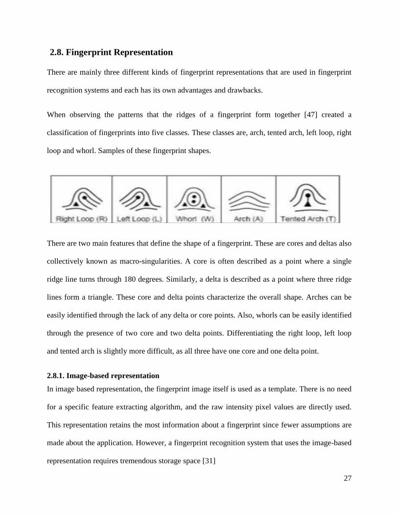
When observing the patterns that the ridges of a fingerprint form together [47] created a
classification of fingerprints into five classes. These classes are, arch, tented arch, left loop, right
loop and whorl. Samples of these fingerprint shapes.
There are two main features that define the shape of a fingerprint. These are cores and deltas also
collectively known as macro-singularities. A core is often described as a point where a single
ridge line turns through 180 degrees. Similarly, a delta is described as a point where three ridge
lines form a triangle. These core and delta points characterize the overall shape. Arches can be
easily identified through the lack of any delta or core points. Also, whorls can be easily identified
through the presence of two core and two delta points. Differentiating the right loop, left loop
and tented arch is slightly more difficult, as all three have one core and one delta point.
2.8.1. Image-based representation
In image based representation, the fingerprint image itself is used as a template. There is no need
for a specific feature extracting algorithm, and the raw intensity pixel values are directly used.
This representation retains the most information about a fingerprint since fewer assumptions are
made about the application. However, a fingerprint recognition system that uses the image-based
representation requires tremendous storage space [31]
28
2.8.2. Global Ridge Pattern representation
This representation relies on the ridge structure, global landmarks and ridge pattern
characteristic, such as the singular points, ridge orientation map, and the ridge frequency map.
This representation is sensitive to the quality of the fingerprint images [32]. However, the
discriminative abilities of this representation are limited due to absence of singular points.
2.8.3. Local Ridge Detail representation
This is the most widely used and studied fingerprint representation. Local ridge details are the
discontinuities of local ridge structure referred to as minutiae. Sir Francis Galton (1822-1922)
was the first person who observed the structures and permanence of minutiae. Therefore,
minutiae are also called ―Galton details‖. They are used by forensic experts to match two
fingerprints.
There are about 150 different types of minutiae [32]. categorized based on their configuration.
Among these minutia types, ―ridge ending‖ and ―ridge bifurcation‖ are the most used, since all
other types of minutiae can be seen as the combinations of ―ridge endings‖ and ―ridge
bifurcation after the fingerprint ridge thinning, marking minutia points is relatively easy.
However, to extract the minutiae from a poor quality image is not an easy task. At present, most
of the automatic fingerprint recognition systems are designed to use minutiae as their fingerprint
representations include this research.
2.8.4. Intra-ridge Detail representation
On every ridge of the finger epidermis, there are many tiny sweat pores. Pores are considered to
be highly distinctive in terms of their numbers, positions, and shapes [32]. However, extracting
29
pores is feasible only in high-resolution fingerprint images and with good image quality.
Therefore, this kind of representation is not practical for most applications.
2.9. Review of Related Works
Many researchers have proposed fingerprinting approaches and they tried to find the best
algorithm that can produce fingerprint images with minimum noise and has maximum
performance.
Lin Hong et al [28] has developed a novel filter bank based fingerprint elastic matching to
capture both local and global details in a fingerprint as a compact fixed-length finger code.
Fingerprint matching is based on the Euclidean distance between the two corresponding finger
codes [3] [11].Fingerprint recognition is being widely applied for personal identification with the
purpose of high degree of security. Fingerprint recognition requires minimal effort from the user
and capture other information than strictly necessary for the recognition process and provides
relatively good performance. Also, another reason for the popularity of fingerprints is the
relatively low price of fingerprint sensors, which enable easy integration into PC keyboards,
smart cards and wireless hardware [11]. The database (DB) consists of a total of 2672 images for
fingerprint identification and verification. Evaluation result shows that the proposed technique
achieves 88% as mean accuracy, 1.92% false accepts rate and 10% false reject rate using identify
and verify the fingerprint images. The limitation of this algorithm is the preprocessing images
not well done.
Dhamal [33] has presented a fingerprint matching scheme that utilized both the frequency and
orientation information available in a fingerprint with eight Gabor filters are used to extract

30
features from the template and input images. The primary advantage of their approach is
computationally attractive matching capability and compact length of Finger Code [33].
This method includes two main advantages of their approach computational attractive matching
and compact length of finger code. Based on filtering based matching and Gabor Filter technique
and Small DB, New DB and Finger DB. Small DB contains 4 different. New DB is a small
database contains 14 fingerprint images. The Finger DB contains fingerprint images of 21
persons. The proposed method improves the accuracy up to 93.7% by using Gabor Filter
algorithm identification system in comparison with other works.
Manvjeet Kaur et al[34] proposed fingerprint verification system using minutiae extraction
technique. In this system they have introduced combined methods to build a minutia extractor
and a minutia matcher. Segmentation with morphological operations used to improve thinning,
false minutiae removal, minutia marking. For this system they have used Histogram Equalization
(HE) and FFT for fingerprint image enhancement and CN concept for minutiae extraction [34].
The proposed research combined methods to build a minutia extractor and a minutia matcher
method. This algorithm uses Histogram Equalization and FFT for enhancement and CN concept
for minutiae extraction for determining preprocessing which has powerful capability in capturing
the directional information for improving the quality of finger images. The accuracy rate of the
identification and verification system is 75%.
Ishpreet Singh Virk and Raman Maini[35] have used histogram equalization for fingerprint
image enhancement, segmentation using Morphological operations, minutia marking by
specially considering the triple branch counting, branch into three terminations, an alignment-
based elastic matching algorithm minutia unification by decomposing has been developed for
31
minutia matching were implemented. The proposed alignment- based elastic matching algorithm
is capable of finding the correspondences between minutiae without resorting to exhaustive
search [35]. This method achieved has been evaluated using FAR of 0.06% FRR of 6.9%.
Madhuriet.al. [20] proposed that there exist many human recognition techniques which were
based on fingerprints. Most of these techniques used minutiae points for fingerprint illustration
and matching. On the other hand, these techniques were not rotation invariant and fail when
enrolled image of a person was matched with a rotated test image. Moreover, such techniques
failed when partial fingerprint images are matched. This paper proposed a fingerprint recognition
technique which uses limited robust features for fingerprint representation and matching [20]
Experiments were performed using a file of 200 images collected from 100 subjects, 2 images
per subject. The technique had produced a recognition accuracy of 99.46% with an equivalent
error rate of 0.54% [20].
32
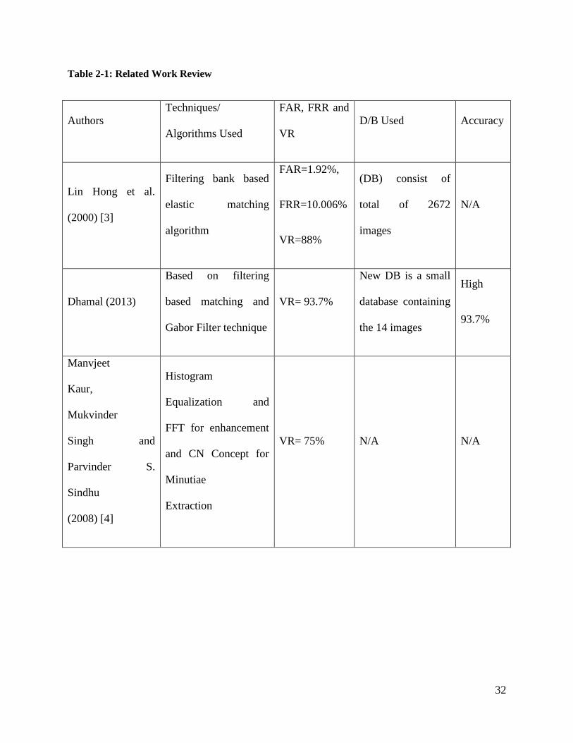
Table 2-1: Related Work Review
Authors
Techniques/
Algorithms Used
FAR, FRR and
VR
D/B Used Accuracy
Lin Hong et al.
(2000) [3]
Filtering bank based
elastic matching
algorithm
FAR=1.92%,
FRR=10.006%
VR=88%
(DB) consist of
total of 2672
images
N/A
Dhamal (2013)
Based on filtering
based matching and
Gabor Filter technique
VR= 93.7%
New DB is a small
database containing
the 14 images
High
93.7%
Manvjeet
Kaur,
Mukvinder
Singh and
Parvinder S.
Sindhu
(2008) [4]
Histogram
Equalization and
FFT for enhancement
and CN Concept for
Minutiae
Extraction
VR= 75% N/A N/A

33
F. A. Afsar,
M. Arif and
M. Hussain
(2004) [5]
Gabor filter based
Enhancement and
CN concept for
Minutiae Extraction
FAR= 1%
FRR= 7%
EER= 5%
FVC 2000 800
fingerprints from
110 different
fingers
High
92%
Ishpreet
Singh Virk
and Raman
Maini (2012)
[5]
Histogram
Equalization for
enhancement and
CN Concept for
Minutiae Extraction
FAR= 0.06%
FRR= 6.9%
FVC2000 N/A
Generally, all the above researches are to work in biometric identification and detection, using
fingerprint identification and verification. Eventhough there are several related works carried out
on fingerprint identification and detection in the field of digital image processing, the
development of automatic fingerprint identification system using image processing techniques
for the recognition fingerprint.

34
CHAPTER THREE
Design and Implementation of Fingerprint Identification
and verification
3.1. Overview
Law enforcement identification is composed of two interdependent subsystems: the ten print
criminal identification subsystem and the latent criminal investigation subsystem [30]. Each
subsystem operates with a considerable amount of autonomy, and both are vital to public safety.
The ten print subsystem is tasked with identifying sets of inked or live scan fingerprints incident
to an arrest or citation or as part of an application process to determine whether a person has an
existing record or not.
In many systems, identification personnel are also charged with maintaining the integrity of the
fingerprint and criminal history databases. Identification bureau staffs are generally composed of
fingerprint technicians and supporting clerical personnel.
An automated ten print inquiry normally requires a minutiae search of only the thumbs or index
fingers. Submitted fingerprints commonly have sufficient clarity and detail to make searching of
more than two fingers unnecessary.
The latent print or criminal identification subsystem is tasked with solving crimes though the
identification of latent prints developed from crime scenes and physical evidence. Terminals
used within the latent subsystem are often specialized to accommodate the capture and digital
enhancement of individual latent prints. The latent subsystem may be staffed by latent print
examiners, crime scene investigators, or laboratory or clerical personnel. The staff of the latent

35
subsystem is frequently under a different command structure than the ten print subsystems and is
often associated with the crime laboratory.
The search of a latent print is more tedious and time-consuming than a ten print search. Latent
prints are often fragmentary and of poor image quality. Minutiae features are normally reviewed
one-by-one before the search begins. Depending on the portion of the database selected to be
searched and the system’s search load, the response may take from a few minutes to several
hours to return. This research paper is to use both ten fingerprint and latent fingerprint minutiae
extraction and matching using image processing techniques and tools.
3.2. Fingerprint recognition
Fingerprint recognition technology is divided into two distinct processes to define a problem of
resolving the identity of a person with different inherent complexities which is verification and
identification [18].
3.2.1. Fingerprint verification process
In the verification process the user states who he or she is and a fingerprint is taken and
compared to the user's previously registered fingerprint. If the fingerprints match, the user is
"verified" as who he or she says he or she is. Since the newly acquired fingerprint is compared to
only one stored fingerprint, this is called a one-to-one matching process. As in the enrollment
process where when fingerprint verification is done, only the fingerprint template is used in the
comparison, not the actual image of the fingerprint.
3.2.2. Fingerprint identification process
In the identification process the user doesn't need to state who he or she is. A fingerprint is taken
and compared to each fingerprint in the database of registered users. When a match occurs, the

36
user is "identified" as the existing user of the system found. Since the newly acquired fingerprint
is compared to many stored fingerprints, this is called a one-to-many matching process. As in the
verification process, when fingerprint identification is done, only the fingerprint template is used
in the comparison, not the actual image of the fingerprint.
Classification is the final stage of any image processing system where each unknown pattern is
assigned to a category, in this thesis any finger print is categorized as criminal, if it has matched
with the a fingerprint in the database, else it is categorized as non-criminal.
3.3. System Architecture
Fingerprint recognition accuracy heavily depends on the quality of a fingerprint image. There are
some basic recommendations and constraints when using fingerprint recognition applications.
The architecture of a fingerprint-based automatic identification system is consists of four
components: (i) image template, (ii) preprocessing, (iii) feature extraction, and (iv)minutiae
matching. Image template is the first task needed after the capture of an image alignment. The
features commonly used to identify the orientation and location of the fingerprint is the
bifurcations and terminations. This approach is the standard used on most facial biometric
algorithms.
The system database consists of a collection of records, each of which corresponds to criminal
person that has recorded before. The task of building database is to record fingerprints into the
system database. When the fingerprint images are fed to the system, a minutiae extraction
algorithm is first applied to the fingerprint images and the minutiae patterns are extracted. If a
fingerprint image is of poor quality, it is enhanced to improve the clarity of ridge/valley
structures and mask out all the regions that cannot be reliably recovered. The enhanced
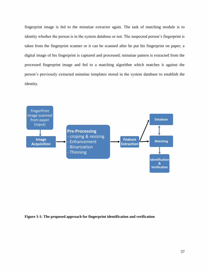
37
fingerprint image is fed to the minutiae extractor again. The task of matching module is to
identity whether the person is in the system database or not. The suspected person’s fingerprint is
taken from the fingerprint scanner or it can be scanned after he put his fingerprint on paper; a
digital image of his fingerprint is captured and processed; minutiae pattern is extracted from the
processed fingerprint image and fed to a matching algorithm which matches it against the
person’s previously extracted minutiae templates stored in the system database to establish the
identity.
Figure 3-1: The proposed approach for fingerprint identification and verification
FingerPrint image scanned
from paper (input)
Image Acquisition
Pre-Processing - croping & resizing - Enhancement - Binarization - Thinning
Feature Extraction
Database
Matching
Identification &
Verification

38
3.4. Fingerprint Image Preprocessing
Preprocessing is a common name for operations with images at lowest level of abstraction. The
aim of Preprocessing is an improvement of the image data that suppresses unwanted distortions
or enhances some image features important for further processing.
Figure 3-2: Original input image
3.4.1 Cropping and Resizing Finger Print Images
Cropping of Images can be done when specific information is to be queried from within an
image. For example, when we have a picture which has a fingerprint image in the paper, the
image can be filled with white background and the color of the fingerprint and the result is
required to be the similar fingerprint. The input original image is cropped using a built-in
MATLAB function imcrop. Since the image has lot of information like text at the edge, these
confuse the system and it would yield irrelevant results, cropping helps to improve the quality of
the result by removing these information and other noises at the edge of the scanned image. Then

39
the images are resized using imresize tool in MATLAB to a 200 x 200 pixel to give a square
matrix in order to make easy for next operations.
Figure 3-3: Resized image
3.4.2. Fingerprint Image Enhancement
Fingerprint Image enhancement is to make the image clearer for easy further Operations. Since
the fingerprint images acquired from sensors device is not assured with perfect quality, those
enhancement methods, for increasing the contrast between ridges and furrows and for connecting
the false broken points of ridges due to insufficient amount of ink, are very useful for keep a
higher matching to fingerprint identification. In this thesis the Frequency Fourier Transform is
applied to the original image after it is normalized and orientation is performed.
The image was divided into small processing blocks 32 by 32 pixels and Fourier Transform is
performed. In order to enhance a specific block by its dominant frequencies, the FFT of the block
was multiplied by its magnitude a set of times.
Equation 3-1: FFT equation to enhance a specific block [18]
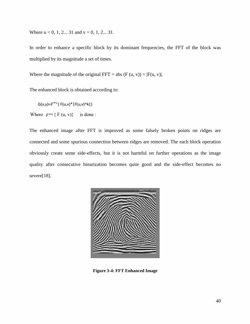
40
Where u = 0, 1, 2... 31 and v = 0, 1, 2... 31.
In order to enhance a specific block by its dominant frequencies, the FFT of the block was
multiplied by its magnitude a set of times.
Where the magnitude of the original FFT = abs (F (u, v)) = |F(u, v)|.
The enhanced block is obtained according to:
The enhanced image after FFT is improved as some falsely broken points on ridges are
connected and some spurious connection between ridges are removed. The each block operation
obviously create some side-effects, but it is not harmful on further operations as the image
quality after consecutive binarization becomes quite good and the side-effect becomes no
severe[18].
Figure 3-4: FFT Enhanced Image

41
3.4.3. Fingerprint Binarization
Binarization is the process of converting the gray scale image into a binary image [27]. Zeros
and ones forms binary image. In a gray-scale image, a pixel can take on 256 different intensity
values while each pixel is assigned to be either black or white in a black and white image. Global
threshold algorithm is used for performing binarization process, which uses a threshold value to
convert a gray-scale to black and white Looking at each pixel on the fingerprint image and
deciding whether it should be converted to black (0) or white (255) when compared with
threshold level. A critical component in the binarization process is choosing a correct value for
the threshold. The threshold values used in this study were selected empirically by trial and error.
Figure 3-5 shows a binary image from the binarization algorithm and the selected ridge pixels,
and the rest of the pixels are filled in white.
Figure 3-5: Binarized image
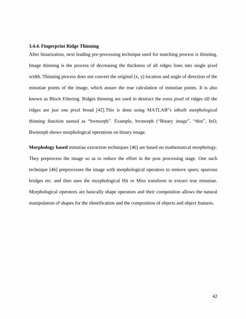
42
3.4.4. Fingerprint Ridge Thinning
After binarization, next leading pre-processing technique used for matching process is thinning.
Image thinning is the process of decreasing the thickness of all ridges lines into single pixel
width. Thinning process does not convert the original (x, y) location and angle of direction of the
minutiae points of the image, which assure the true calculation of minutiae points. It is also
known as Block Filtering. Ridges thinning are used to destruct the extra pixel of ridges till the
ridges are just one pixel broad [42].This is done using MATLAB‟s inbuilt morphological
thinning function named as ―bwmorph‖. Example, bwmorph (―Binary image‖, ―thin‟, Inf);
Bwmorph shows morphological operations on binary image.
Morphology based minutiae extraction techniques [46] are based on mathematical morphology.
They preprocess the image so as to reduce the effort in the post processing stage. One such
technique [46] preprocesses the image with morphological operators to remove spurs; spurious
bridges etc. and then uses the morphological Hit or Miss transform to extract true minutiae.
Morphological operators are basically shape operators and their composition allows the natural
manipulation of shapes for the identification and the composition of objects and object features.
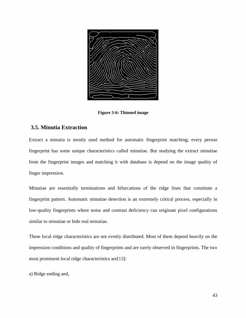
43
Figure 3-6: Thinned image
3.5. Minutia Extraction
Extract a minutia is mostly used method for automatic fingerprint matching; every person
fingerprint has some unique characteristics called minutiae. But studying the extract minutiae
from the fingerprint images and matching it with database is depend on the image quality of
finger impression.
Minutiae are essentially terminations and bifurcations of the ridge lines that constitute a
fingerprint pattern. Automatic minutiae detection is an extremely critical process, especially in
low-quality fingerprints where noise and contrast deficiency can originate pixel configurations
similar to minutiae or hide real minutiae.
These local ridge characteristics are not evenly distributed. Most of them depend heavily on the
impression conditions and quality of fingerprints and are rarely observed in fingerprints. The two
most prominent local ridge characteristics are[13]:
a) Ridge ending and,

44
b) Ridge bifurcation.
A ridge ending is defined as the point where a ridge ends abruptly. A ridge bifurcation is
defined as the point where a ridge forks or diverges into branch ridges. Collectively, these
features are called minutiae. Most of the fingerprint extraction and matching techniques restrict
the set of features to two types of minutiae: ridge endings and ridge bifurcations.
Each of the ridge endings and ridge bifurcations types of minutiae has three attributes, namely,
the x-coordinate, the y-coordinate, and the local ridge direction (θ). Many other features have
been derived from this basic three- dimensional feature vector. Given the minutiae representation
of fingerprints, matching a fingerprint against a database reduces to the problem of point
matching [42].
This method extracts the ridge endings and bifurcations from the skeleton image by examining
the local neighborhood of each ridge pixel using a 3×3 window. The method used for minutiae
extraction is the crossing number (CN) method. This method involves the use of the skeleton
image where the ridge flow pattern is eight connected. The minutiae are extracted by scanning
the local neighborhood of each ridge pixel in the image using a 3×3 window. CN is defined as
half the sum of the differences between the pairs of adjacent pixel. The ridge pixel can be
divided into bifurcation, ridge ending and non-minutiae point based on it. A ridge ending point
has only one neighbor, a bifurcation point possesses more than two neighbors, and a normal
ridge pixel has two neighbors. A CN value of zero refers to an isolated point, value of one to a
ridge ending, two to a continuing ridge point, three to a bifurcation point and a CN of four means
a crossing point. Minutiae detection in a fingerprint skeleton is implemented by scanning thinned
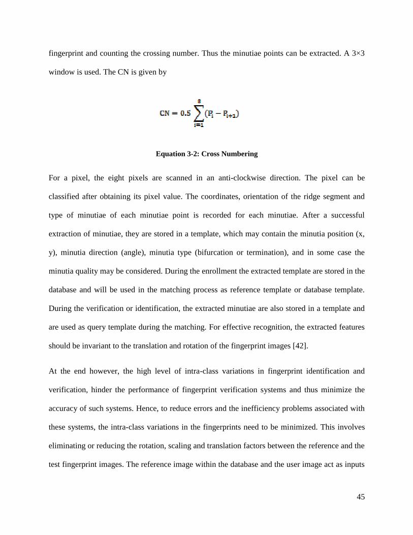
45
fingerprint and counting the crossing number. Thus the minutiae points can be extracted. A 3×3
window is used. The CN is given by
Equation 3-2: Cross Numbering
For a pixel, the eight pixels are scanned in an anti-clockwise direction. The pixel can be
classified after obtaining its pixel value. The coordinates, orientation of the ridge segment and
type of minutiae of each minutiae point is recorded for each minutiae. After a successful
extraction of minutiae, they are stored in a template, which may contain the minutia position (x,
y), minutia direction (angle), minutia type (bifurcation or termination), and in some case the
minutia quality may be considered. During the enrollment the extracted template are stored in the
database and will be used in the matching process as reference template or database template.
During the verification or identification, the extracted minutiae are also stored in a template and
are used as query template during the matching. For effective recognition, the extracted features
should be invariant to the translation and rotation of the fingerprint images [42].
At the end however, the high level of intra-class variations in fingerprint identification and
verification, hinder the performance of fingerprint verification systems and thus minimize the
accuracy of such systems. Hence, to reduce errors and the inefficiency problems associated with
these systems, the intra-class variations in the fingerprints need to be minimized. This involves
eliminating or reducing the rotation, scaling and translation factors between the reference and the
test fingerprint images. The reference image within the database and the user image act as inputs

46
to the system. Feature extraction is done from the reference fingerprint which describes certain
characteristics of the fingerprint and stored as a template. For identification and verification, the
same features are extracted from the test fingerprint and compared to the template [45].
3.5.1. Minutia Marking
After the fingerprint ridge thinning and extract, marking minutia points is relatively easy. The
concept of Crossing Number (CN) is used for extracting the minutiae. The extracted minutiae
then can be marked as ridge ending or bifurcation. For minutiae marking generally a 3x3 window
is taken, if the central pixel is 1 and has 3 one value neighbors in its 8-connected neighborhood,
then the central pixel is a ridge bifurcation and if the central pixel is 1 and has one has only 1 one
-value in its 8-connected neighborhood, then it is a ridge end [42].
Figure 3-7: Minutia marking image

47
3.6. Minutia Post-processing
3.6.1. False Minutia Removal
The pre-processing stage of a fingerprint image does not remove all the errors. For instance, false
ridge breaks and ridge cross-connections due to insufficient amount of inking and over inking are
not completely eliminated. Actually all the previous stages themselves occasionally introduce
some errors which further lead to spurious minutia. This false minutia significantly affects the
accuracy of matching only if they are regarded as genuine minutia. So, some mechanisms of
removing these false minutiae are essential in order to keep the fingerprint verification system
effective [3].
3.6.2. Euclidean Distance
In comparison of binary images distance play a very important role in the fields of local features,
morphological operations and distance between two points in an image. Commonly Euclidean
distance is a natural distance between two points which is generally mapped with a ruler. The
distance between minutiae points in a fingerprint image. Definition of Euclidean distance is the
straight line distance between two points. By default Bwdist uses the Euclidean distance metric.
Binary images can have any number of dimensions where D is the same size as Binary image.
Euclidean distance simply refers to the distance between two points as measured in a straight
line. The advantage of using Euclidean distance in biometric recognition system is reportedly
faster than most other means of determining correlation and it compares the relationship between
actual ratings are for specific preferences or items [28].

48
Equation 3-3: Euclidean Distance
There are several types of false minutiae, but here in this thesis it is considered only seven types
of false minutiae.
Figure 3-8: False Minutia Removal
1. If the distance between a bifurcation and a termination is less than threshold distance, D, and
both the minutia are in the same ridge (case a), then both of them are removed. Here D is the
average inter-ridge width which represents the average distance between two parallel
neighboring ridges.
a b c d
e f g

49
2. If two bifurcations are present in the same ridge and the distance between them is less than
threshold distance, D, then both bifurcations is removed. (Cases b and c).
3. If the distance between two terminations is less than threshold distance, D and their directions
are almost coincident with only a small angle variation. And they satisfy the condition that no
other termination is located in between the two terminations. Then, both the terminations are
regarded as false minutia and are considered as part of a broken ridge, hence removed. (Case d,
e, f).
4. If the distance between two terminations of a very short ridge is less than threshold distance,
D, then it is considered as a false minutia and is removed (case g).
3.6.3. ROI
In general, only a Region of Interest (ROI) is useful to be recognized for each fingerprint image.
The image area without effective ridges and furrows is discarded since it only holds background
information. This was achieved using Morphological operations. The two Morphological
operations called ―OPEN‟ and ―CLOSE‟ are adopted. The ―OPEN‟ operation can expand
images and remove peaks introduced by background noise. The ―CLOSE‟ operation can shrink
images and eliminate small cavities [8] [24].

50
Figure 3-9: segmented image
3.7. Fingerprint Matching
3.7.1. Minutiae Match
After successfully extracting the set of minutia of two fingerprint images, the minutia match
algorithm determines whether the two minutia sets are from the same finger or not. An
alignment-based match algorithm is used in our work. It includes two consecutive stages. First is
alignment stage and second is match stage. In alignment stage two fingerprint images to be
matched, choose any one minutia from each image, calculate the similarity of the two ridges
associated with the two referenced minutia points. If the similarity is larger than a threshold
value which is 75% in this study, (the threshold is selected in experimental tests described in
table 4.1) transform each set of minutia to a new coordination system whose origin is at the
referenced point and whose x-axis is coincident with the direction of the referenced point.
At the matching stage, the approach is elastically match minutia which is achieved by placing a
bounding box around each template minutia. If the minutia to be matched is within the rectangle
box and the direction discrepancy between them is very small, then the two minutias are

51
regarded as a matched minutia pair. Each minutia in the template image either has no matched
minutia or has only one corresponding minutia. [40], [41].
The identification of a person requires the comparison of his/her fingerprint with all the
fingerprints in a database, which in large scale applications may be very large (several million
fingerprints). A common strategy to reduce the number of comparisons during fingerprint
retrieval and, consequently, to improve the response time of the identification process, is to
divide the fingerprints into some predefined classes.
A fingerprint matching module computes a match score between two fingerprints, which should
be high for fingerprints from the same finger and low for those from different fingers.
Fingerprint matching is a difficult pattern-recognition problem due to large interclass variations
in fingerprint images of the same finger and large interclass similarity between fingerprint
images from different fingers.
Most fingerprint-matching algorithms adopt one of four approaches: image correlation, phase
matching, skeleton matching, and minutiae matching. Minutiae-based representation is
commonly used [47], primarily because
• Forensic examiners have successfully relied on minutiae to match fingerprints for more than a
century,
• Minutiae-based representation is storage efficient, and
• Expert testimony about suspect identity based on matched minutiae is admissible in courts of
law.
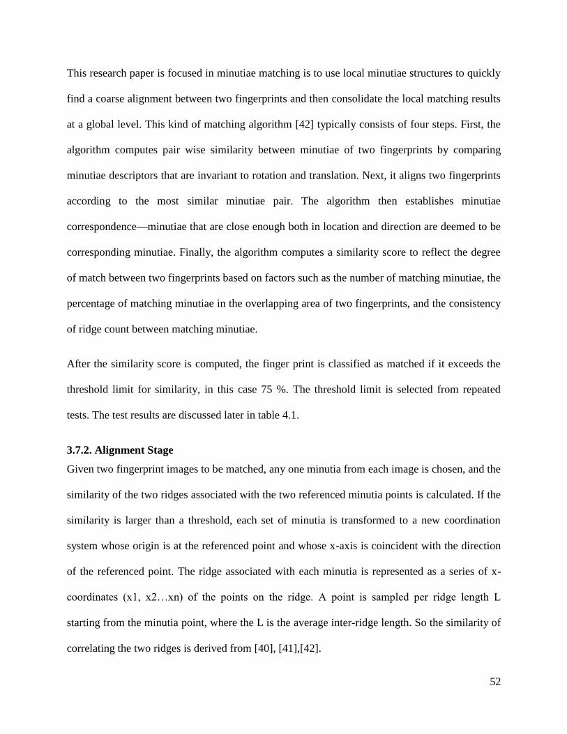
52
This research paper is focused in minutiae matching is to use local minutiae structures to quickly
find a coarse alignment between two fingerprints and then consolidate the local matching results
at a global level. This kind of matching algorithm [42] typically consists of four steps. First, the
algorithm computes pair wise similarity between minutiae of two fingerprints by comparing
minutiae descriptors that are invariant to rotation and translation. Next, it aligns two fingerprints
according to the most similar minutiae pair. The algorithm then establishes minutiae
correspondence—minutiae that are close enough both in location and direction are deemed to be
corresponding minutiae. Finally, the algorithm computes a similarity score to reflect the degree
of match between two fingerprints based on factors such as the number of matching minutiae, the
percentage of matching minutiae in the overlapping area of two fingerprints, and the consistency
of ridge count between matching minutiae.
After the similarity score is computed, the finger print is classified as matched if it exceeds the
threshold limit for similarity, in this case 75 %. The threshold limit is selected from repeated
tests. The test results are discussed later in table 4.1.
3.7.2. Alignment Stage
Given two fingerprint images to be matched, any one minutia from each image is chosen, and the
similarity of the two ridges associated with the two referenced minutia points is calculated. If the
similarity is larger than a threshold, each set of minutia is transformed to a new coordination
system whose origin is at the referenced point and whose x-axis is coincident with the direction
of the referenced point. The ridge associated with each minutia is represented as a series of x-
coordinates (x1, x2…xn) of the points on the ridge. A point is sampled per ridge length L
starting from the minutia point, where the L is the average inter-ridge length. So the similarity of
correlating the two ridges is derived from [40], [41],[42].
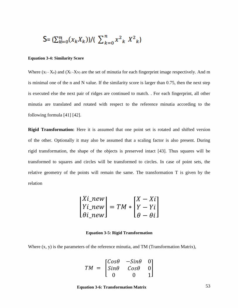
53
Equation 3-4: Similarity Score
Where (xi ~ Xn) and (Xi ~XN) are the set of minutia for each fingerprint image respectively. And m
is minimal one of the n and N value. If the similarity score is larger than 0.75, then the next step
is executed else the next pair of ridges are continued to match. . For each fingerprint, all other
minutia are translated and rotated with respect to the reference minutia according to the
following formula [41] [42].
Rigid Transformation: Here it is assumed that one point set is rotated and shifted version
of the other. Optionally it may also be assumed that a scaling factor is also present. During
rigid transformation, the shape of the objects is preserved intact [43]. Thus squares will be
transformed to squares and circles will be transformed to circles. In case of point sets, the
relative geometry of the points will remain the same. The transformation T is given by the
relation
⌊
⌋ [
]
Equation 3-5: Rigid Transformation
Where (x, y) is the parameters of the reference minutia, and TM (Transformation Matrix),
[
]
Equation 3-6: Transformation Matrix

54
3.7.3. Match Stage
After we get two sets of transformed minutia points, we use the elastic match algorithm to count
the matched minutia pairs by assuming two minutiae having nearly the same position and
direction are identical. The matching algorithm for the aligned minutia patterns needs to be
elastic since the strict match requiring that all parameters (x, y, θ) are the same for two identical
minutiae is impossible due to the slight deformations and inexact quantization of minutiae.
3.7.4. Decision making matching
Decision making is done on the basis of the percentage of image matched, if more than the
threshold limit of the features matched; images are classified as similar. If less than the threshold
limit of minutiae features matched; the two images are different images. Depending on the
setting of the threshold in identification systems, sometimes several reference templates can be
considered matches to the trial template, with the better scores corresponding to better matches.
The final match ratio for two fingerprints is the number of total matched pairs divided by the
number of minutiae of the template fingerprint. The score is 100*ratio and ranges from 0 to 100.
If the score is larger than a pre-specified threshold the two fingerprints are from the same finger,
and if the score is less the two fingerprints are different.
55
CHAPTER FOUR
Experimentation
In this chapter, we discuss the experiments carried out to test the effectiveness of our
proposed system. Accordingly, the type of identification and verification, the data set used and
the results achieved in the identification and verification of fingerprint process will be discussed.
4.1. Dataset
In this study images are taken from Ethiopian federal police commission fingerprint
identification system data center. A total of 300 fingerprint images that were on the paper are
taken and digitalized by using optical scanner. From those images we have selected 245
fingerprints as criminals. And the rest are considered as innocent.
In both places the images are taken in certain parameters. In order to take the image
optical scanner was used to capture the images with the following parameter.
All the images are scanned in JPEG (Joint Photographer Expert Group) file format
Since the scanned image contains all ten fingerprint images of a person in one, the images
are sliced and isolated, in order to give ten single fingerprint images for each fingers.
Finally, all images are cropped to remove unnecessary edge information, then resized to a
200 x 200 pixels image by the MATLAB function, imresize, If the image is larger than
200x200 pixel the function decreases the image size and if the image is less than 200 x
200 it is enlarged to have equal sized images.

56
4.2. Experimental Setup
MATLAB version R2016a tool is used to develop the prototype of the system. Moreover,
the specification of the computer on which the system is implemented is Intel Core i3
laptop computer with 4GB RAM and 2.3 GHz processor.
4.2.1 Experiment: Determining Threshold for Similarity Score
The test is performed to determine the threshold limit in order to classify suspected fingerprint as
criminal or non – criminal. In doing so, several fingerprint image samples are tested for the
matching score, from these the similarity score of images that were already in the database and
new fingerprints are recorded. Then the threshold limit is selected in such a way that the system
can identify matched fingerprints. To perform the experimentation 110 fingerprint images are
used, the fingerprint images are selected as follows
• 55 images from the database
• 55 images out of the database
Thus, the threshold limit for the matching score is selected in order to let the system to identify
150 fingerprints which are from the database, as matched. The accuracy of the system is
quantified in terms of false Matching ratio (FMR) and the False Non-Matching Ratio (FNR).
4.2.2. Experimental Result and Analysis
Table 4.1 shows the obtained result the experiment. The tables report the behavior of the False
Matching Ratio, FMR, and the False Non-matching Ratio, FNR, with respect to Similarity Score
Threshold Value.
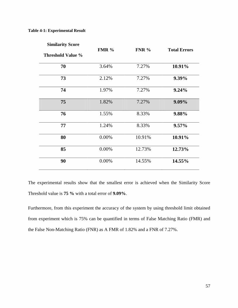
57
Table 4-1: Experimental Result
Similarity Score
Threshold Value %
FMR % FNR % Total Errors
70 3.64% 7.27% 10.91%
73 2.12% 7.27% 9.39%
74 1.97% 7.27% 9.24%
75 1.82% 7.27% 9.09%
76 1.55% 8.33% 9.88%
77 1.24% 8.33% 9.57%
80 0.00% 10.91% 10.91%
85 0.00% 12.73% 12.73%
90 0.00% 14.55% 14.55%
The experimental results show that the smallest error is achieved when the Similarity Score
Threshold value is 75 % with a total error of 9.09%.
Furthermore, from this experiment the accuracy of the system by using threshold limit obtained
from experiment which is 75% can be quantified in terms of False Matching Ratio (FMR) and
the False Non-Matching Ratio (FNR) as A FMR of 1.82% and a FNR of 7.27%.
58
CHAPTER FIVE
Conclusion and Recommendation
As fingerprint recognition, verification and identification become very popular nowadays, the
main intent of this research is to design fingerprint identification and verification system with
scanned images from paper using image processing tools. On the work the effort is to select
feature extraction and matching techniques to enhance the performance of the fingerprint
identification system.
On the present work an attempt is made to feature extraction and matching techniques that are
crucial to enhance the performance of the fingerprint image identification system.
5.1. Conclusion
In is study an effort to study and understand how a fingerprint identification and verification
system is used as a form of biometrics to recognize identities of human beings. It includes all the
stages mentioned in the foregoing study. The outcome of the experiment shows that the proposed
technique can be adopted on large databases such as that of a country like Ethiopia.
The reliability of any automatic fingerprint identification and verification system strongly relies
on the precision obtained in the minutia extraction process. A number of factors damage the
correct location of minutia. Among them, poor image quality is the one with most influence. The
proposed minutiae matching algorithm is capable of finding the correspondences between
minutiae without resorting to exhaustive research. However, there is a scope of further
improvement in terms of efficiency and accuracy which can be achieved by improving the
hardware to capture the image or by improving the image enhancement techniques.

59
In this study it is proposed to use a scanned image after the person puts his fingerprint on the
paper to detect and classify the suspected person as criminal or non-criminal. A preprocessing is
applied on images for enhancement using median filtering for image noise removal. Except for
different rotation angles and other limitations of the images, the system provides a result of
classification accuracy. The proposed system uses ridge end and bifurcation information
contained in the minutiae. In general, image processing fingerprint identification and verification
system offers a means to improve the efficiency of traditional system to achieve better
investigative accuracy.
The feature extraction algorithms are used, namely; minutiae based feature extraction. Using the
feature extraction algorithms, one dimensional feature vector is constructed. The proposed
system uses ridge end and bifurcation information contained in the minutiae. In general, image
processing fingerprint identification and verification system offers a means to improve the
efficiency of traditional system to achieve better investigative accuracy.
Finally, the accuracy of the system by using threshold limit obtained from experiment which is
75% can be quantified in terms of False Matching Ratio (FMR) and the False Non-Matching
Ratio (FNR) as A FMR of 1.82% and a FNR of 7.27% with a Total Error 9.09% and accuracy
90.1%.
The study has strength in determining matching score for images with noise and poor quality due
to the process of putting fingerprint on the paper with ink on the fingers and using the digitally
scanned image of this as input.
This study has a weakness to extract all necessary features that helps to attain good results while
matching. Due to the time limitation and the difficulty of the algorithms only edge ending and
bifurcations are taken as features.

60
5.2. Recommendation
Although this research has significance in getting the required information from scanned images,
there are some matters that need further study to develop efficient and effective system.
In this study, fingerprint feature extraction and matching algorithms are by minutiae base
algorithm, and the matching is based on alignment fingerprint minutiae images. Minutiae
used as a feature are only ending and bifurcation. Hence, future works should focus on
other minutiae like core and deltas for better accuracy.
Pre-processing techniques like noise removal helps to increase the effectiveness and
efficiency of the system. Introducing advanced techniques on these areas improve the
performance of fingerprint image identification system.
The algorithms used to calculate the similarity score can be improved in order to give fast
recognition system.
Using large local dataset and test on this algorithm and others too.
The matching value can be computed irrespective of orientation of the fingerprint.
Better segmentation techniques can be considered in the future.

61
6. References
[1] D. D. J. A. P. Maltoni, Handbook of Fingerprint Recognition., 2003 .
[2] K. K. J. O.-G. HartwigFronthaler, in Fingerprint Recognition, pp. 9-10.
[3] S. a. E. Walia, "Analysis of various biometric techniques ,," international journal of
computer science and Information technologies , pp. 1595-1597, 2012.
[4] N. M. a. A. Otti, "Fingerprint Recognition," pp. 19-29, 2011.
[5] U. C. a. S. Bhardwaj, "Fingerprint image enhancement and minutia extraction,"
International Journal of Advanced Resarech in Computer Science and Management Studies,
2014.
[6] R. Thai, Fingerprint Image Enhancement and Minutiae Extraction,, the School of Computer
Science and Software Engineering, the University of Western Australia, 2003.
[7] M. S. a. P. S. S. M. Kaur, "Fingerprint Verification System using Minutiae Extraction
Technique," Proceedings of World Academy of Science, Engineering and Technology, vol.
36, December 2008.
[8] K. a. Dr.E.Chandra, "Frequency Domain Enhancement Algorithim based on LOg- Gabor
Filter in FFT Domain," Global Journal of Computer Science and Technology, 2012.
[9] P. V. Prateek Verma Maheedhar Dubey, "Correlation based method for identification of
fingerprint-a biometric approach," International Journal of Engineering and Advanced
Technology, pp. 2249-8958, 2012.
[10] A. B. a. A. W. Amira Saleh, fingerprint Recognition, Ain Shamas University,Egypt:
Computer and system engineering deparetement Faculty of Engineering , 2011

62
[11] F. S. P. L. H. n. S. P. Anni K. Jain, Filterbank Based Fingerprint Matching, IEEE
Transaction On Image Processing, 2000.
[12] M. S. K. Z. A. A. a. H. A. Zeki, "Fingerprint Image Enhancement by develop Mehtre
Technique," ACIJ, 2011.
[13] M. D. J. A. P. S. Maltoni D, Handbook of Fingerprint Recognition, London, U.K, Springer;
2009..
[14] R. A. a. Rosenfeld, Point pattern matching by relaxation, Pattern Recognition, 1993.
[15] C. S. a. J. A. Ratha N, An Adaptive flow orientation based feature extraction in fingerprint
images , Pattern recognition, 1995.
[16] M.-S. L. A.-F. Fierrez-Aguilar, "On the effects of image quality degradation on minutiae -
and ridge -based automatic fingerprint recognition," 2005.
[17] Joseph P . Hornak, "Encyclopedia of Imaging Science and Technology(John Wiley &
Sons,2002 ) ISBN," CRC Press,Florida, pp. 1-38, 1995.
[18] D. a. J. H. K.R.Rao, Fast Fourier Transform:Algorithims and applications,
heidelberg,Germany, spr 2010.
[19] Merssa, Police and its Professional Ethics, 2011.
[20] Madhuri and R.Mishra, "Fingerprint Recognition using Robust Local Features," vol. 2,
2012.
[21] P. Namburu, A study on Fingerprint image enhancement and minutiae, 2007.
[22] B. Y. L. Xuejun Tan Bhanu, Fingerprint classification based on Learned features, Aug 2005.
[23] A. N. B. Muhamad, "Minutiae point extraction for skeleton based fingerprint images," 2008.
[24] Z. S. Barham, Fingerprint Recognition using Matlab, 2011.
63
[25] Wuzhili, "Fingerprint Recognition," p. 20, 19 April 2002.
[26] A. U. U. H. R. Jain, "Hiding a Face in a Fingerprint Image.," ICPR, pp. 756-759, 2002.
[27] M. S. K. Z. A. A. a. H. A. Zeki, "Fingerprint Image Enhancement by develop Mehtre
Technique," ACIJ, 2011.
[28] Y. W. a. A. J. L.Hong, "fingerprin image enhancement:Algorithm and performance
evalution; Pattern Recognition and Image Processing Laboratory," pp. 1-30, 2006.
[29] S. N. Chikkerur, "Impact of singular point detection on fingerprint matching performance,"
2005.
[30] C. Brislawn, "The FBI compression standard for digitized fingerprint images," SPIE, vol.
2847, pp. 344-355, Aug 1996.
[31] a. A. A.Ross J. Shah, "reconstraction fingerprint from minutiae points," IEEE, pp. 544-560,
2007.
[32] A.K. Jain et al, "An identify autentication system using fingerprints," IEEE, vol. 85, no. 9,
pp. 1365-1388, 1997.
[33] D. R. Balaso, "A Noval approach for Fingerprint Matching using Gabor Filters,"
International Journal of Latest Trends in Engineering and Technology , 2013.
[34] M. Kaur, M. Singh and P. S. Sindhu, ―Fingerprint Verification System using Minutiae
Extraction Technique,‖ Proceedings of World Academy of Science, Engineering and
Technology, vol. 36, December 2008
[35] I. S. V. a. R. Maini, "Fingerprint Image Enhancement and Minutiae Matching in Fingerprint
Verification," Journal of Computing Technologies, vol. 1, June 2012.
[36] A. S. N.Akbari, "Automation of fingerprint Recognition Using OCT fingerprint Images".
[37] O.D. Trier and T. Taxt, "Evaluation of binarization methods for document images," IEEE,

64
vol. 17, pp. 312-315, Mar 1995.
[38] Graig T . Diefenderfer, Fingerprint Recognition, California: Naval Postgraduate.
[39] N. Ratha and S. A. Chen, "A Real-Time Macthing System for Large Fingerprint Database,,"
IEEE Tran., vol. 18, August 1996.
[40] J. S. a. E.Backer, "Finding Point Correspondence Using Simulated Annealing," Pattern
Recognition, vol. 28, pp. 231-240, 1995.
[41] A.Ranade and A Rosenfeld, "Point Pattern Matching by Relaxation," Pattern Recognition,
vol. 12, no. 2, pp. 269-275, 1993.
[42] J. Feng, "Combining Minutiea Descrption for Fingerprint Matching," Pattern Recognition ,
pp. 342-352, Jan. 2008.
[43] W. a. E. Gonzalez, Digital Image Processing, Prentice Hall, 2004.
[44] D. S. a. Bab-Hadiashar, "fingerprint segmentation using the phase of multiscale Gabor
Waveletes," in proceeding of the fifth asian conference on computer vision , 2002.
[45] M. H. a. V. Thakar, "Image Registration for recovering affine transformation using Nelder
mead Simple method for optimization," International Journal of Image Processing(IJIP),
vol. 3, no. 5, pp. 218-221, 2009.
[46] P. S. P. .. B. R. Bansal, "Effective Morphological Extraction of True Fingerprint Minutiae
based on the Hit or Miss Transform," IJBB, vol. 4, pp. 71-85, 2010.
[47] H. E. R., classification and uses of fingerprint HM stationery office,, 1905.
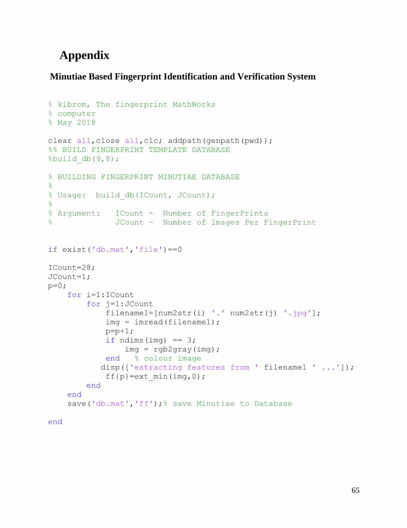
65
Appendix
Minutiae Based Fingerprint Identification and Verification System
% kibrom, The fingerprint MathWorks
% computer
% May 2018
clear all,close all,clc; addpath(genpath(pwd));
%% BUILD FINGERPRINT TEMPLATE DATABASE
%build_db(9,8);
% BUILDING FINGERPRINT MINUTIAE DATABASE
%
% Usage: build_db(ICount, JCount);
%
% Argument: ICount - Number of FingerPrints
% JCount - Number of Images Per FingerPrint
if exist('db.mat','file')==0
ICount=28;
JCount=1;
p=0;
for i=1:ICount
for j=1:JCount
filename1=[num2str(i) '.' num2str(j) '.jpg'];
img = imread(filename1);
p=p+1;
if ndims(img) == 3;
img = rgb2gray(img);
end % colour image
disp(['extracting features from ' filename1 ' ...']);
ff{p}=ext_min(img,0);
end
end
save('db.mat','ff');% save Minutiae to Database
end
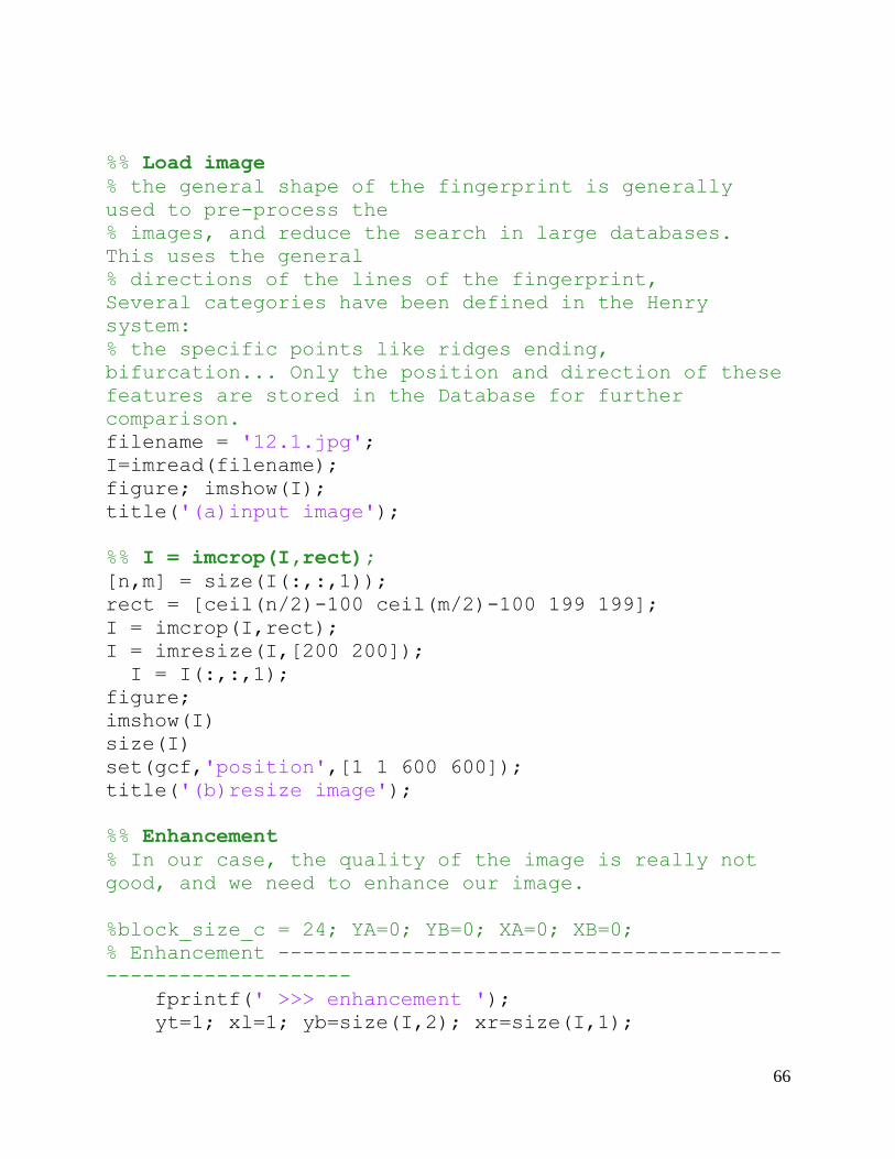
66
%% Load image
% the general shape of the fingerprint is generally
used to pre-process the
% images, and reduce the search in large databases.
This uses the general
% directions of the lines of the fingerprint,
Several categories have been defined in the Henry
system:
% the specific points like ridges ending,
bifurcation... Only the position and direction of these
features are stored in the Database for further
comparison.
filename = '12.1.jpg';
I=imread(filename);
figure; imshow(I);
title('(a)input image');
%% I = imcrop(I,rect);
[n,m] = size(I(:,:,1));
rect = [ceil(n/2)-100 ceil(m/2)-100 199 199];
I = imcrop(I,rect);
I = imresize(I,[200 200]);
I = I(:,:,1);
figure;
imshow(I)
size(I)
set(gcf,'position',[1 1 600 600]);
title('(b)resize image');
%% Enhancement
% In our case, the quality of the image is really not
good, and we need to enhance our image.
%block_size_c = 24; YA=0; YB=0; XA=0; XB=0;
% Enhancement -----------------------------------------
--------------------
fprintf(' >>> enhancement ');
yt=1; xl=1; yb=size(I,2); xr=size(I,1);

67
for x=1:55
if numel(find(I(x,:)<200)) < 8
I(1:x,:) = 255;
yt=x;
end
end
for x=225:size(I,1)
if numel(find(I(x,:)<200)) < 3
I(x-17:size(I,1),:) = 255;
yb=x;
break
end
end
for y=200:size(I,2)
if numel(find(I(:,y)<200)) < 1
I(:,y:size(I,2)) = 255;
xr=y;
break
end
end
for y=1:75
if numel(find(I(:,y,1)<200)) < 1
I(:,1:y,1) = 255;
xl=y;
end
end
[ enhimg, binI, mask, cimg, cimg2, orient_img,
orient_img_m ] = f_enhance(I);
I=enhimg;
figure,imshow(I);
set(gcf,'position',[1 1 600 600]);
fprintf('done.');
title('(c)enhaced image');

68
%% Binarize
% We binarize the image. After the operation, ridges in
the fingerprint are
% highlighted with black color while furrow are white.
% J=I(:,:,1)>160;
% J=I;
J = binI;
figure,imshow(J)
set(gcf,'position',[1 1 600 600]);
title('(d)binarize image');
%% Thining
% Ridge thining is to eliminate the redundant pixels of
ridges till the
% ridges are just one pixel wide.
K=bwmorph(~J,'thin','inf');
figure,imshow(~K)
set(gcf,'position',[1 1 600 600]);
title('(e)thinning image');
%% Minutiae
% We filter the thinned ridge map by the filter
"minutie". "minutie"
% compute the number of one-value of each 3x3 window:
% * if the central is 1 and has only 1 one-value
neighbor, then the central
% pixel is a termination.
% * if the central is 1 and has 3 one-value neighbor,
then the central
% pixel is a bifurcation.
% * if the central is 1 and has 2 one-value neighbor,
then the central
% pixel is a usual pixel.
fun=@minutie;
L = nlfilter(K,[3 3],fun);
%% Termination
LTerm=(L==1);
LTermLab=bwlabel(LTerm);

69
propTerm=regionprops(LTermLab,'Centroid');
CentroidTerm=round(cat(1,propTerm(:).Centroid));
imshow(~K)
set(gcf,'position',[1 1 600 600]);
hold on
plot(CentroidTerm(:,1),CentroidTerm(:,2),'ro')
title('(f)termination image');
%% Bifurcation
LBif=(L==3);
LBifLab=bwlabel(LBif);
propBif=regionprops(LBifLab,'Centroid','Image');
CentroidBif=round(cat(1,propBif(:).Centroid));
plot(CentroidBif(:,1),CentroidBif(:,2),'go')
title('(g)bifurcation image');
%% Remarks
% We have a lot of spurious minutae.
% We are going to process them.
% process 1: if the distance between a termination and
a biffurcation is
% smaller than D, we remove this minutiae
% process 2: if the distance between two biffurcations
is
% smaller than D, we remove this minutia
% process 3: if the distance between two terminations
is
% smaller than D, we remove this minutia
D=6;
%% Process 1
Distance=DistEuclidian(CentroidBif,CentroidTerm);
SpuriousMinutae=Distance<D;
[i,j]=find(SpuriousMinutae);
CentroidBif(i,:)=[];
CentroidTerm(j,:)=[];
%% Process 2
Distance=DistEuclidian(CentroidBif);

70
SpuriousMinutae=Distance<D;
[i,j]=find(SpuriousMinutae);
CentroidBif(i,:)=[];
%% Process 3
Distance=DistEuclidian(CentroidTerm);
SpuriousMinutae=Distance<D;
[i,j]=find(SpuriousMinutae);
CentroidTerm(i,:)=[];
%%
hold off
imshow(~K)
hold on
plot(CentroidTerm(:,1),CentroidTerm(:,2),'ro')
plot(CentroidBif(:,1),CentroidBif(:,2),'go')
hold off
%% ROI
% We have to determine a ROI. For that, we consider the
binary image, and
% we aply an closing on this image and an erosion.
% With the GUI, I allow the use of ROI tools of MATLAB,
to define manually
% the ROI.
Kopen=imclose(K,strel('square',10));
KopenClean= imfill(Kopen,'holes');
KopenClean=bwareaopen(KopenClean,5);
imshow(KopenClean)
KopenClean([1 end],:)=0;
KopenClean(:,[1 end])=0;
ROI=imerode(KopenClean,strel('disk',10));
imshow(ROI)
71
title('(h)roi image');
%%
%% Suppress extreme minutiae
Once we defined the ROI, we can suppress minutiae
external to this ROI.
[m,n]=size(I(:,:,1));
indTerm=sub2ind([m,n],CentroidTerm(:,1),CentroidTerm(:,
2));
Z=zeros(m,n);
Z(indTerm)=1;
ZTerm=Z.*ROI';
[CentroidTermX,CentroidTermY]=find(ZTerm);
indBif=sub2ind([m,n],CentroidBif(:,1),CentroidBif(:,2))
;
Z=zeros(m,n);
Z(indBif)=1;
ZBif=Z.*ROI';
[CentroidBifX,CentroidBifY]=find(ZBif);
imshow(I)
hold on
plot(CentroidTermX,CentroidTermY,'ro','linewidth',2)
plot(CentroidBifX,CentroidBifY,'go','linewidth',2)
%% Orientation
% Once we determined the differents minutiae, we have
to find the
% orientation of each one
Table=[3*pi/4 2*pi/3 pi/2 pi/3 pi/4
5*pi/6 0 0 0 pi/6
pi 0 0 0 0
-5*pi/6 0 0 0 -pi/6
-3*pi/4 -2*pi/3 -pi/2 -pi/3 -pi/4];
%% Termination Orientation
% We have to find the orientation of the termination.
% For finding that, we analyze the position of the
pixel on the boundary of
72
% a 5 x 5 bounding box of the termination. We compare
this position to the
% Table variable. The Table variable gives the angle in
radian.
for ind=1:length(CentroidTermX)
Klocal=K(CentroidTermY(ind)-
2:CentroidTermY(ind)+2,CentroidTermX(ind)-
2:CentroidTermX(ind)+2);
Klocal(2:end-1,2:end-1)=0;
[i,j]=find(Klocal);
if length(i)~=1
Mlocal=K(CentroidTermY(ind)-
1:CentroidTermY(ind)+1,CentroidTermX(ind)-
1:CentroidTermX(ind)+1);
Mlocal(2,2)=0;
[i,j]=find(Mlocal);
i=2*i-1;
j=2*j-1;
end
OrientationTerm(ind,1)=min(Table(i,j));
end
dxTerm=sin(OrientationTerm)*5;
dyTerm=cos(OrientationTerm)*5;
figure
imshow(K)
set(gcf,'position',[1 1 600 600]);
hold on
plot(CentroidTermX,CentroidTermY,'ro','linewidth',2)
plot([CentroidTermX CentroidTermX+dyTerm]',...
[CentroidTermY CentroidTermY-
dxTerm]','r','linewidth',2)
title('thinn hold termi image');
%% Bifurcation Orientation
% For each bifurcation, we have three lines. So we
operate the same
% process than in termination case three times.
for ind=1:length(CentroidBifX)

73
Klocal=K(CentroidBifY(ind)-
2:CentroidBifY(ind)+2,CentroidBifX(ind)-
2:CentroidBifX(ind)+2);
Klocal(2:end-1,2:end-1)=0;
[i,j]=find(Klocal);
if length(i)~=3
CentroidBifY(ind)=NaN;
CentroidBifX(ind)=NaN;
OrientationBif(ind,:)=NaN;
dxBif(ind,:)=0;
dyBif(ind,:)=0;
else
for k=1:3
OrientationBif(ind,k)=Table(i(k),j(k));
dxBif(ind,k)=sin(OrientationBif(ind,k))*5;
dyBif(ind,k)=cos(OrientationBif(ind,k))*5;
end
end
end
plot(CentroidBifX,CentroidBifY,'go','linewidth',2)
OrientationLinesX=[CentroidBifX
CentroidBifX+dyBif(:,1);CentroidBifX
CentroidBifX+dyBif(:,2);CentroidBifX
CentroidBifX+dyBif(:,3)]';
OrientationLinesY=[CentroidBifY CentroidBifY-
dxBif(:,1);CentroidBifY CentroidBifY-
dxBif(:,2);CentroidBifY CentroidBifY-dxBif(:,3)]';
plot(OrientationLinesX,OrientationLinesY,'g','linewidth
',2)
%% Save Minutia in a one Matrix M
% In this step, we are going to save the minutia in a
file
MinutiaTerm=[CentroidTermX,CentroidTermY,OrientationTer
m];
MinutiaBif=[CentroidBifX,CentroidBifY,OrientationBif];

74
% size of minutia; length = length of (MinutiaTerm +
MinutiaBif), width = 6
%
M = MinutiaTerm(:,1:2);
M(:,3) = 1;
M(:,4) = MinutiaTerm(:,3);
m = size(MinutiaTerm,1);
n = size(MinutiaBif,1);
M(m+1:m+n,1:2) = MinutiaBif(:,1:2);
M(m+1:m+n,3) = 3;
%Select one of three bifurcation angles (Minimum in
this case)
for i = m+1:m+n
M(i,4) = min(MinutiaBif(i-m,3:5));
end
M(:,5) = 0;
M(:,6) = 1;
%% Minutia Match
% Given two set of minutia of two fingerprint images,
the minutia match
% algorithm determines whether the two minutia sets are
from the same
% finger or not.
% two steps:
% 1. Alignment stage
% 2. Match stage
%
% For this step, I would need a database
%% GET FEATURES OF AN ARBITRARY FINGERPRINT FROM THE
TEMPLATE AND MATCH IT WITH FIRST ONE
load('db.mat'); %i=2;
% % filename='imagee.jpg'; % filename should be the
required finger print for testing
% % img2 = imread(filename);
% % if ndims(img2) == 3; img2 = rgb2gray(img2); end %
Color Images
75
% % disp(['Extracting features from ' filename '
...']);
% % ffnew=ext_min(img2);
num_per = 28;%size(ff,2) % total no. of data =num_per *
num_fin
num_fin = 10;
S=zeros(num_per*num_fin,1)
for i=1:num_per
for j=1:num_fin
second=[num2str(i) '.' num2str(j)];
fprintf(['\n']);
fprintf(['Computing similarity between '
filename ' and ' second ' from kibromDB : ']);
k = (i-1)*10+j;
S(k) = match(M,ff{k},0);
fprintf([num2str(S(k))]);
end
end
%findmax similraty index
[maxval, maxind] = max(S(:));
if maxval>0.75
fprintf(['\n']);
fprintf(['Fingerprint Macth from the Database
Found']);
fprintf(['\n']);
fprintf(['Verification >>>']);
second=[num2str(fix((maxind-1)/10)+1) '.'
num2str(mod(maxind-1,10)+1)];
fprintf(['\n']);
fprintf(['Similarity for ' filename ' is found with
' second ' from kibromDB : ']);
ss = match(M,ff{maxind},1);
else
fprintf(['\n']);
fprintf(['Fingerprint Macth from the Database not
Found']);

76
end