Finestone Stucco System - BASF USA - Home STUCCO SYSTEM TYPICAL FINESTONE STUCCO SYSTEM WITH CMU...
16
1. Typical Finestone Stucco System with Steel Framing 2. Typical Finestone Stucco System with Wood Framing 3. Typical Finestone Stucco System with CMU 4. Typical Finestone Stucco System with CMU and Plaster Base 5. Typical Finestone Stucco System with EPS Insulation Board 6. Typical Finestone Stucco System with Channeled EPS Insulation Board 7. Typical Surface Control Joint 8. Typical Expansion Joint 9. Typical Drainage at Floorline 10. Typical Clad Window Jamb 11. Typical Clad Window Head 12. Typical Clad Window Sill 13. Typical Primed Window Head 14. Typical Primed Window Jamb 15. Typical Primed Window Sill 16. Typical EPS Shape Application 17. Typical Termination at Soffit/Gable End 18. Typical Termination at Foundation 19. Typical Kick-out Flashing 20. Typical Termination at Deck 21. Typical Coping 22. Typical Corner Bead 23. Typical Downspout Application 24. Typical Pipe Penetration 25. Typical Light Fixture 26. Typical Dryer Vent Typical Details Finestone Stucco System Cement Plaster Stucco
Transcript of Finestone Stucco System - BASF USA - Home STUCCO SYSTEM TYPICAL FINESTONE STUCCO SYSTEM WITH CMU...

1. Typical Finestone Stucco System with Steel Framing
2. Typical Finestone Stucco System with Wood Framing
3. Typical Finestone Stucco System with CMU
4. Typical Finestone Stucco System with CMU and Plaster Base
5. Typical Finestone Stucco System with EPS Insulation Board
6. Typical Finestone Stucco System with Channeled EPS Insulation Board
7. Typical Surface Control Joint
8. Typical Expansion Joint
9. Typical Drainage at Floorline
10. Typical Clad Window Jamb
11. Typical Clad Window Head
12. Typical Clad Window Sill
13. Typical Primed Window Head
14. Typical Primed Window Jamb
15. Typical Primed Window Sill
16. Typical EPS Shape Application
17. Typical Termination at Soffit/Gable End
18. Typical Termination at Foundation
19. Typical Kick-out Flashing
20. Typical Termination at Deck
21. Typical Coping
22. Typical Corner Bead
23. Typical Downspout Application
24. Typical Pipe Penetration
25. Typical Light Fixture
26. Typical Dryer Vent
Typical Details
Finestone Stucco System Cement Plaster Stucco

Notes:• Verify all materials are installed in accordance with installation instructions and applicable code.• Basic requirements for water-resistive barrier: - One layer minimum No.15 felt on non-wood based sheathing. - Two layers minimum Grade D on wood based sheathing. - Finestone RA with one layer minimum Grade D as slip sheet on wood and non-wood based sheathing. - The use of PermaLath requires the use of a polymeric water-resistive barrier. - Comply with applicable local building code.• Basic requirements for Plaster Base: - StuccoBase 3/8” to 1/2” thickness: PermaLath, or min. 1” 20 ga. wire, min. 2.5 lb/sq.yd. metal lath or acceptable alternative. - StuccoBase min. 1/2” to nominal 7/8” thickness: PermaLath 1000 or min. 1 1/2” 17 ga. wire, min. 2.5 lb/sq.yd. metal lath or acceptable alternative.
TYPICAL FINESTONE STUCCO SYSTEM WITH STEEL FRAMING
TYPICAL FINESTONE STUCCO SYSTEM WITH WOOD FRAMING
FSWS-01 0211
FSWS-02 0211
Notes:• Verify all materials are installed in accordance with installation instructions and applicable code.• Basic requirements for water-resistive Barrier: - Two layers minimum Grade D on wood based sheathing. - One layer minimum No.15 felt on non-wood based sheathing. - Finestone RA with one layer minimum Grade D as slip sheet on wood and non-wood based sheathing. - The use of PermaLath requires the use of a polymeric water-resistive barrier. - Comply with applicable local building code.• Basic requirements for Plaster Base: - StuccoBase 3/8” to 1/2” thickness: PermaLath, or min. 1” 20 ga. wire, min. 2.5 lb/sq.yd. metal lath or acceptable alternative. - StuccoBase min. 1/2” to nominal 7/8” thickness: PermaLath 1000 or min. 1 1/2” 17 ga. wire, min. 2.5 lb/sq.yd. metal lath or acceptable alternative.

FINESTONE STUCCO SYSTEM
TYPICAL FINESTONE STUCCO SYSTEM WITH CMU
TYPICAL FINESTONE STUCCO SYSTEM WITH CMU AND PLASTER BASE
FSWS-03 0211
FSWS-04 0211
Notes:• Verify all materials are installed in accordance with installation instructions and applicable code.• StuccoBase min. 3/8” thickness to max. 5/8” thickness. Thicknesses greater than 5/8” require the use of PermaLath 1000 or acceptable metal plaster base.
Notes:• Verify all materials are installed in accordance with installation instructions and applicable code.• Basic requirements for Plaster Base: - StuccoBase 3/8” to 1/2” thickness: PermaLath, or min. 1” 20 ga. wire, min. 2.5 lb/sq.yd. metal lath or acceptable alternative. - StuccoBase min. 1/2” to nominal 7/8” thickness: PermaLath 1000 or min. 1 1/2” 17 ga. wire, min. 2.5 lb/sq.yd. metal lath or acceptable alternative.

Notes:• Verify all materials are installed in accordance with installation instructions and applicable code.• Basic requirements for water-resistive barrier: - One layer Tyvek StuccoWrap or DrainWrap. - Finestone RA and grooved EPS insulation board. - The use of PermaLath requires the use of a polymeric water-resistive barrier. - Comply with applicable local building code.• Basic requirements for Plaster Base: - StuccoBase 3/8” to 1/2” thickness: PermaLath, or min. 1” 20 ga. wire, min. 2.5 lb/sq.yd. metal lath or acceptable alternative. - StuccoBase min. 1/2” to nominal 7/8” thickness: PermaLath 1000 or min. 1 1/2” 17 ga. wire, min. 2.5 lb/sq.yd. metal lath or acceptable alternative.
TYPICAL FINESTONE STUCCO SYSTEM WITH EPS INSULATION BOARD
TYPICAL FINESTONE STUCCO SYSTEM WITH CHANNELED EPS INSULATION BOARD
FSWS-05 0211
FSWS-06 0211
Notes:• Verify all materials are installed in accordance with installation instructions and applicable code.• Basic requirements for water-resistive Barrier: - One layer 60 Min. Grade D paper or equivalent . - Finestone RA. - Comply with applicable local building code.• Basic requirements for Plaster Base: - StuccoBase 3/8” to 1/2” thickness: PermaLath, or min. 1” 20 ga. wire, min. 2.5 lb/sq.yd. metal lath or acceptable alternative. - StuccoBase min. 1/2” to nominal 7/8” thickness: PermaLath 1000 or min. 1 1/2” 17 ga. wire, min. 2.5 lb/sq.yd. metal lath or acceptable alternative.• EPS channels on insulation board are a minimum 1/4” wide x 1/8” deep x 12” o.c.

FINESTONE STUCCO SYSTEM
TYPICAL SURFACE CONTROL JOINT
TYPICAL EXPANSION JOINT
FSWS-07 0211
FSWS-08 0211
Notes:• Verify all materials are installed in accordance with installation instructions and applicable code.• Provide control joints at a maximum 144 sq.ft. and placement as determined by the design professional. • Install per requirements of ASTM C1063.• Lath must be broken at the joint accessory.
Notes:• Verify all materials are installed in accordance with installation instructions and applicable code.• Install expansion joints in the system at all changes in substrate, through existing expansion joints, and where movement is anticipated. It is the sole responsibility of the design professional to determine specific expansion joint location, placement and design.• Install per requirements of ASTM C1063.• Lath must be broken at the joint accessory.• If using Finestone RA, replace WS Wrap with WS Flash.

TYPICAL DRAINAGE AT FLOORLINE
TYPICAL CLAD WINDOW - JAMB
FSWS-09 0211
FSWS-10 0211
Notes:• Verify all materials are installed in accordance with installation instructions and applicable code.• Water-resistive barrier shall be installed over flashing.• Water-resistive barrier shall be installed up and behind flashing before terminating. • Install per requirements of ASTM C1063.• Lath must be broken at the joint accessory.• It is recommended that a means for drainage is provided at every floor.
Notes:• Verify all materials are installed in accordance with installation instructions and applicable code.• Ensure water-resistive barrier is properly applied into the rough openings in accordance with application guidelines. See Secondary Moisture Protection Barrier Guidelines for Finestone Stucco Wall System technical bulletin.

FINESTONE STUCCO SYSTEM
TYPICAL CLAD WINDOW - HEAD
TYPICAL CLAD WINDOW - SILL
FSWS-11 0211
FSWS-12 0211
Notes:• Verify all materials are installed in accordance with installation instructions and applicable code.• Ensure water-resistive barrier is properly applied over the head flashing. See Secondary Moisture Protection Barrier Guidelines for Finestone Stucco Wall System technical bulletin.• Provide end-dams at flashing terminations.• If using Finestone RA, replace WS Wrap with WS Flash.
Notes:• Verify all materials are installed in accordance with installation instructions and applicable code.• Ensure water-resistive barrier is properly applied into the rough openings in accordance with application guidelines. See Secondary Moisture Protection Barrier Guidelines for Finestone Stucco Wall System technical bulletin.• If using Finestone RA, replace WS Wrap with WS Flash.
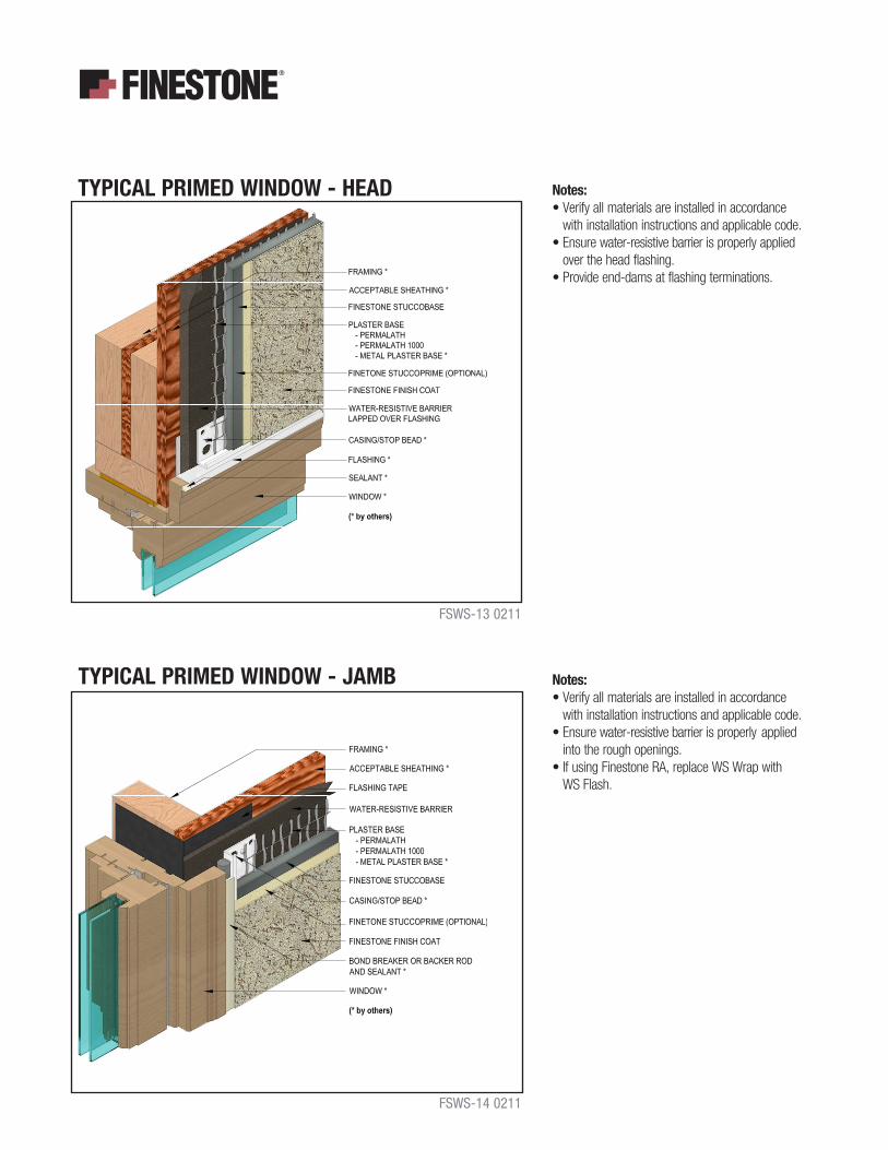
Notes:• Verify all materials are installed in accordance with installation instructions and applicable code.• Ensure water-resistive barrier is properly applied over the head flashing. • Provide end-dams at flashing terminations.
TYPICAL PRIMED WINDOW - HEAD
TYPICAL PRIMED WINDOW - JAMB
FSWS-13 0211
FSWS-14 0211
Notes:• Verify all materials are installed in accordance with installation instructions and applicable code.• Ensure water-resistive barrier is properly applied into the rough openings. • If using Finestone RA, replace WS Wrap with WS Flash.

FINESTONE STUCCO SYSTEM
TYPICAL PRIMED WINDOW - SILL
TYPICAL EPS SHAPE APPLICATION
FSWS-15 0211
FSWS-16 0211
Notes:• Verify all materials are installed in accordance with installation instructions and applicable code.• Ensure water-resistive barrier is properly applied into the rough openings.• If using Finestone RA, replace WS Wrap with WS Flash.
Notes:• Verify all materials are installed in accordance with installation instructions and applicable code.• Overlap reinforced base coat onto StuccoBase a minimum of 76 mm (3”).• On horizontal projections greater than one inch maintain a minimum 6:12 slope.

Notes:• Verify all materials are installed in accordance with installation instructions and applicable code.
TYPICAL TERMINATION AT SOFFIT/GABLE END
TYPICAL TERMINATION AT FOUNDATION
FSWS-17 0211
FSWS-18 0211
Notes:• Verify all materials are installed in accordance with installation instructions and applicable code.• Per ASTM C1063 terminate the stucco wall system a minimum of 102 mm (4”) above raw earth and 51 mm (2”) above paved surface.• Water-resistive barrier shall be installed over weep screed flange.

FINESTONE STUCCO SYSTEM
TYPICAL KICK-OUT FLASHING
TYPICAL TERMINATION AT DECK
FSWS-19 0211
FSWS-20 0211
Notes:• Verify all materials are installed in accordance with installation instructions and applicable code.• Terminate Stucco Wall System a minimum of 50 mm (2”) above roof.• Ensure step flashing is a minimum 50 mm (2”) behind Finestone Stucco System.• Kick-out flashing a minimum 100 mm (4”) in height. • Kick-out flashing shall be angled a minimum 100° with seams sealed or soldered.• Ensure a means for drainage is provided at system termination at roof.
Notes:• Verify all materials are installed in accordance with installation instructions and applicable code.• Water-resistive barrier shall be installed over flashing.• Water-resistive barrier shall be installed up and behind metal flashing before terminating.

Notes:• Verify all materials are installed in accordance with installation instructions and applicable code.• Extend coping a minimum of 51 mm (2”) on to face of Finestone Stucco System and seal drip edge.• Water-resistive barrier shall be installed up and over the top and extended down the other side.
TYPICAL COPING
TYPICAL CORNER BEAD
FSWS-21 0211
FSWS-22 0211
Notes:• Verify all materials are installed in accordance with installation instructions and applicable code.• Attach corner bead over plaster base.• Water-resistive barrier shall be installed continuous around corner a minimum of 305 mm (12”).• Corner bead shall be filled solid with StuccoBase.

FINESTONE STUCCO SYSTEM
TYPICAL DOWNSPOUT APPLICATION
TYPICAL PIPE PENETRATION
FSWS-23 0211
FSWS-24 0211
Notes:• Verify all materials are installed in accordance with installation instructions and applicable code.• Properly seal all penetrations through the stucco wall system.
Notes:• Verify all materials are installed in accordance with installation instructions and applicable code.• Properly seal all penetrations through the stucco wall system.

TYPICAL LIGHT FIXTURE
FSWS-25 0211
Notes:• Verify all materials are installed in accordance with installation instructions and applicable code.• Properly seal all penetrations through the stucco wall system. .
TYPICAL DRYER VENT
FSWS-26 0211
Notes:• Verify all materials are installed in accordance with installation instructions and applicable code.• Properly seal all penetrations through the stucco wall system.

NOTES
Note BASF Wall Systems is an operating unit of BASF Corporation (herein referred to as “BASF Wall Systems”)
Residential PolicyApply wall systems in accordance with local building codes in force at the time of construction. On one and two-family residential framed construction, BASF Wall Systems requires that the wall system selected be one that includes provisions for moisture drainage.
DisclaimerThis information and all further technical advice are based on BASF Wall Systems’ present knowledge and experience. However, BASF assumes no liability for providing such information and advice including the extent to which such information and advice may relate to existing third party intellectual property rights, especially patent rights. In particular, BASF Wall Systems disclaims any and all CONDITIONS AND WARRANTIES, WHETHER EXPRESS OR IMPLIED, INCLUDING THE IMPLIED WARRANTIES OF FITNESS FOR A PARTICULAR PURPOSE OR MERCHANTABILITY. BASF WALL SYSTEMS SHALL NOT BE RESPONSIBLE FOR CONSEQUENTIAL, INDIRECT OR INCIDENTAL DAMAGES (INCLUDING LOSS OF PROFITS) OF ANY KIND. BASF Wall Systems reserves the right to make any changes according to technological progress or further developments. It is the customer’s responsibility and obligation to carefully inspect and test any incoming goods.Performance of the product(s) described herein should be verified by testing andcarried out only by qualified experts. It is the sole responsibility of the customer to carry out and arrange for any such testing. Reference to trade names used by other companies is neither a recommendation, nor an endorsement of any product and does not imply that similar products could not be used. It is the responsibility of both the specifier and the purchaser to determine if a product is suitable for its intended use. The designer selected by the purchaser shall be responsible for all decisions pertaining to design, detail, structural capability, attachment details, shop drawings and the like. BASF Wall Systems has prepared guidelines in the form of specifications, typical application details, and product bulletins to facilitate the design process only. BASF Wall Systems is not liable for any errors or omissions in design, detail, structural capability, attachment details, shop drawings or the like, whether based upon the information provided by BASF Wall Systems or otherwise, or for any changes which the purchasers, specifiers, designers or their appointed representatives may make to BASF Wall Systems published comments. For more information visit our website at www.sonowall.basf.com.
BASF Wall Systems 3550 St. Johns Bluff Road South Jacksonville, FL 32224-2614 Phone 800 • 221 • 9255 Fax 904 • 996 • 6300 www.finestone.basf.com
©2011 BASF Corporation Printed in U.S.A. 02/11