FINDING THE OPTIMUM ANGLE OF ATTACK FOR … THE OPTIMUM ANGLE OF ATTACK FOR THE FRONT WING OF AN F1...
6
FINDING THE OPTIMUM ANGLE OF ATTACK FOR THE FRONT WING OF AN F1 CAR USING CFD J. Jagadeep Reddy B. Tech (Mech) IIIrd year VIT, Vellore-14(TN),India e-mail: [email protected] Mayank Gupta B. Tech (Mech) IIIrd year VIT, Vellore-14(TN),India e-mail: [email protected] Abstract:-The F1 car is vehicle designed to obtain maximum speed across a race track. Earlier, the main mode for achieving speed was the development of engine but now aerodynamic forces – downforce and drag – are an object of concern by the team to achieve higher speeds. The ‘drag’ and ‘downforce’ are the two important forces governing the efficiency of a road vehicle. They influence the top straight line speed and cornering speed significantly for an F1 car. This in turn influences the performance of the car. The general design of the vehicle is such that lot of downforce is required to keep the car glued to the track.. The front wing, rear wing and the diffuser are the important components to achieve this. The front wing is supposed to generate about 25% of this ‘downforce’. These forces are dependent on C L & C D which depend on the angle of attack. The paper uses a numerical approach to finding the variation of these parameters on angle of attack using the CFD software FLUENT. In the meshing software ‘GAMBIT’ the boundary conditions for the problem were specified as per the real problem analysis. The Reynold’s number for this kind of flow is between 10 6 to 3*10 6 . Hence, ‘k-ε’ model of turbulence was used. The results were correlated with previous results. Subsequently, the angle of attack was altered for obtaining the parameters at various angles to obtain the optimum angle of attack. Keywords: CFD – computational fluid dynamics, CAE, Reynold’s number, downforce 1. Introduction:- The main objective of the F1 teams is to achieve top speed. Earlier the designers were dependent on the horsepower for achieving their aim but recently they are trying to achieve their aim through aerodynamic forces. The aerodynamic setup for a car can vary considerably between race tracks, depending on the length of the straights and the types of corners; and the optimum setup is always a compromise between the two. The wings fitted to these cars are very significant factors of aerodynamic forces. Negative lift is induced by creating a lower pressure below the wing which is created by higher-velocity airflow below the wing surface. This negative lift comes at a cost. For any amount of lift gained, drag also increases. The drag forces are an important factor in determining the attainable top speed. These forces are determined by the angle of attack set up by the front wing as it is the first part of the car to come in contact with the air. 2.1 Literature:- Angle of attack is a term used in aerodynamics to describe the angle between the airfoil's chord line and the direction of airflow wind, The amount of lift generated by a wing is directly related to the angle of attack, with greater angles generating more lift and more drag. This remains true up to the stall point, where lift starts to decrease again because of airflow separation. A minor change in angle of attack or height of the vehicle has caused the car to Proceedings of the 4th WSEAS International Conference on Fluid Mechanics and Aerodynamics, Elounda, Greece, August 21-23, 2006 (pp29-34)
Transcript of FINDING THE OPTIMUM ANGLE OF ATTACK FOR … THE OPTIMUM ANGLE OF ATTACK FOR THE FRONT WING OF AN F1...
FINDING THE OPTIMUM ANGLE OF ATTACK FOR THE FRONT
WING OF AN F1 CAR USING CFD
J. Jagadeep Reddy
B. Tech (Mech) IIIrd year
VIT, Vellore-14(TN),India
e-mail: [email protected]
Mayank Gupta
B. Tech (Mech) IIIrd year
VIT, Vellore-14(TN),India
e-mail: [email protected]
Abstract:-The F1 car is vehicle designed to obtain maximum speed across a race track. Earlier, the main mode
for achieving speed was the development of engine but now aerodynamic forces – downforce and drag – are an
object of concern by the team to achieve higher speeds. The ‘drag’ and ‘downforce’ are the two important forces
governing the efficiency of a road vehicle. They influence the top straight line speed and cornering speed
significantly for an F1 car. This in turn influences the performance of the car. The general design of the vehicle is
such that lot of downforce is required to keep the car glued to the track.. The front wing, rear wing and the
diffuser are the important components to achieve this.
The front wing is supposed to generate about 25% of this ‘downforce’. These forces are dependent on CL & CD
which depend on the angle of attack. The paper uses a numerical approach to finding the variation of these
parameters on angle of attack using the CFD software FLUENT. In the meshing software ‘GAMBIT’ the
boundary conditions for the problem were specified as per the real problem analysis. The Reynold’s number for
this kind of flow is between 106 to 3*10
6. Hence, ‘k-ε’ model of turbulence was used. The results were correlated
with previous results. Subsequently, the angle of attack was altered for obtaining the parameters at various angles
to obtain the optimum angle of attack.
Keywords: CFD – computational fluid dynamics, CAE, Reynold’s number, downforce
1. Introduction:- The main objective of the F1 teams is to achieve top
speed. Earlier the designers were dependent on the
horsepower for achieving their aim but recently they
are trying to achieve their aim through aerodynamic
forces. The aerodynamic setup for a car can vary
considerably between race tracks, depending on the
length of the straights and the types of corners; and
the optimum setup is always a compromise between
the two.
The wings fitted to these cars are very significant
factors of aerodynamic forces. Negative lift is
induced by creating a lower pressure below the wing
which is created by higher-velocity airflow below
the wing surface. This negative lift comes at a cost.
For any amount of lift gained, drag also increases.
The drag forces are an important factor in
determining the attainable top speed. These forces
are determined by the angle of attack set up by the
front wing as it is the first part of the car to come in
contact with the air.
2.1 Literature:- Angle of attack is a term used in aerodynamics to
describe the angle between the airfoil's chord line
and the direction of airflow wind, The amount of lift
generated by a wing is directly related to the angle of
attack, with greater angles generating more lift and
more drag. This remains true up to the stall point,
where lift starts to decrease again because of airflow
separation. A minor change in angle of attack or
height of the vehicle has caused the car to
Proceedings of the 4th WSEAS International Conference on Fluid Mechanics and Aerodynamics, Elounda, Greece, August 21-23, 2006 (pp29-34)

experience lift, not downforce, sometimes with
disastrous consequences.[1]
The goal of any designer in the wind tunnel is to
maximize negative lift while also minimizing drag.
The greater the Lift-to-Drag ratio, the faster the lap
times ratio, the faster the lap times are. [2]The wind
tunnel provides an effective means of simulating real
flows. Recent works have shown the variation of Cl
& Cd with the angle of attack of high performance
vehicle [3] for wind tunnel testing. In the design of
equipment that depends critically on the flow
behavior, like the aerodynamic design of an aircraft,
full-scale measurement, as part of the design process
is economically impractical. This situation has led to
an increasing interest in the development of a
numerical wind tunnel. Costs incurred by the F1
companies in running the wind-tunnels have been
tabulated for the top four F1 teams in the year 2005
Table 1.
Wind Tunnel Costs[4]
Company
name
Cost incurred in wind tunnel
testing in 2005(in millions
dollars)
1. Ferrari 11.25
2. Mclaren-
Mercedes
9.96
3. BMW-
Wiliiams
9.76
4. Toyota 8.95
This situation has led to an increasing interest in the
development of a numerical wind tunnel. In [5], the
author has calculated the Cl and Cd for an airfoil by
simulating the boundary layer suction theory with a
aerodynamic design program in the FORTRAN
source code.
2.2 CFD Review:- The Physical aspects of any fluid flow are governed
by three fundamental principles: Mass is conserved;
Newton's second law and Energy is conserved.
These fundamental principles can be expressed in
terms of mathematical equations, which in their most
general form are usually partial differential
equations. This branch of fluid dynamics
complements experimental and theoretical fluid
dynamics by providing an alternative cost effective
means of simulating real flows.
Computational Fluid Dynamics is the science of
determining a numerical solution to the governing
equations of fluid flow whilst advancing the solution
through space or time to obtain a numerical
description of the complete flow field of interest.
This branch of fluid dynamics complements
experimental and theoretical fluid dynamics by
providing an alternative cost effective means of
simulating real flows. As such it offers the means of
testing theoretical advances for conditions
unavailable on an experimental basis.
CFD technology is now mature enough to provide
sufficiently accurate results for the external
aerodynamic analysis. Choice of cell shapes, mesh
structures and grid resolution, influences the quality
of the CFD results more than any other single factor.
Most automatic mesh generation strategies use
tetrahedral cells that are highly diffusive, requiring
very large number of cells to produce accurate
results. It is not unusual for an all-tetrahedral mesh
cells to accurately predict flow around an F1 racing
car. Other issues affecting the quality of results
include the choice of turbulence models, choice of
wall treatment, boundary positions and conditions,
and assuming whether flow around the car is steady
or transient. [8] F.Mortel in his thesis [6] in the year
2003 has shown the emphasis of different designs of
airfoils for achieving aerodynamic efficiency. The Cl
variation with the angle of attack for a finite wing
has also been shown. [7]
2.2(a) Airflow Modeling [9]
Airflow modeling based on Computational Fluid
Dynamics (CFD), for the fundamental conservation
equations for mass, momentum and energy in the
form of the Navier-Stokes equation, are:-
Sgradvdivt ϕϕ
ϕϕρρϕ =−+∂
∂ Γ )()(ρ
Transient + Convection- Diffusion=Source
Where, ρ = Density
vρ
= Velocity Vector
ϕ = Dependent variable
=Γϕ Exchange Co-efficient( Laminar+ Turbulent)
Sϕ =Source and Sink
Airflow modeling solves the set of Navier-Stokes
equations by superimposing a grid of many tens or
even hundreds of thousands of cells that describe the
physical geometry and heat sources and air itself.
Proceedings of the 4th WSEAS International Conference on Fluid Mechanics and Aerodynamics, Elounda, Greece, August 21-23, 2006 (pp29-34)
2.2(b) ‘k-ε ’ model
The ‘k-ε ’ model is derived by substituting the sum
of an average term plus a fluctuating term for
he instantaneous quantities in the equations below:-
0=∇+∂
∂u
t
pρ
σρα
ρ ∇=−∇+×−∇+∂
∂gpwuu
t
u)
1(
2
The average terms are expected to vary less than the
instantaneous quantities and, therefore, can be
resolved over a coarser grid. This averaging
procedure yields an additional unknown term called
the Reynold’s Stress ( ''uu iiρ− ). The additional
unknowns are resolved by introducing the eddy
viscosity concept, which results in two additional
transport equations, one each for ‘k’ and ‘ε ’, and
five empirical constants.[10]
For the two-equation model based on both a
transport equation for turbulent kinetic energy k and
a transport equation for the dissipation of turbulent
kinetic energy ε.
A general formulation is given by [11]
2
5)(2))((
xC
xx iik
t
i
KGP
k
Dt
D
∂
∂−−++
∂
∂+
∂
∂= µρεµ
ρε
σ
µ
Equation 1
)(2
)())((
2
4
2
22
311
xxu
CfC
CfCxx
ji
it
i
t
i
k
GPkDt
D
∂∂
∂+−
++∂
∂+
∂
∂=
ρ
µερ
εεµ
ρε
µσ
µ
ε Equation 2
Where )(xu
uu
xu
i
j
j
i
j
i
tP
∂
∂+
∂
∂
∂
∂=µ
And the buoyancy term,
xg
it
t
i
TG
∂
∂=
σ
µβ
The turbulent viscosity µt is obtained from
ερ
µµµ2k
fct= Equation 3
The conventional k-e model is achieved when ƒ1, ƒ2,
ĵ and C3 are equal to one and C4 and C5 are zero. A
low Reynolds number ‘k-ε ’ describing flow close
to a solid surface can be obtained from equations 1,2
and 3 using the following expressions
ƒ1 = C3 = C4 = C5 = 1.0
ƒ2 = 1.0 – 0.3 exp ( - Rt* Rt )
ƒ2 = exp ( -3.4/(1+ Rt/ 50)2)
where the turbulent Reynolds number is
Rt = ρk2/ µε
The iteration procedure in a numerical prediction
often will be stabilized by a high level of turbulence.
Initial iterations can be performed with a high and
constant eddy viscosity and the prediction, at a later
stage, be connected to a k-e model.
3. CAD Model:-
3.1 Front Wing- Model of the front wing was designed in the
‘SOLIDWORKS 2005’ as per the regulations for the
year 2005’ and considering all the above mentioned
factors influencing the aerodynamic properties. The
relevant regulations are tabulated below in table 2
Table 2[12]
Article FIA Formula 1 Technical regulation
1. Overall height
No part of the bodywork may be more than
950mm above the reference plane.
2. Front bodywork height
All bodywork situated forward of a point
lying 330mm behind the front
wheel centre line, and more than 250mm from
the centre line of the car,
must be no less than 100mm and no more
than 300mm above the
reference plane.
3. Bodywork around the front wheels
With the exception of brake cooling ducts, in
plan view, there must be no
bodywork in the area formed by two
longitudinal lines parallel to and 400mm and
900mm from the car centre line and two
transversal lines,
one 350mm forward of and one 800mm
behind the front wheel centre
line.
The wheel was designed with a radius of 330mm,
there wheel were cut on both faces with a circle of
100mm. radius for a depth of 100mm. to make space
for the suspension rods on the inside and for the
wheel mountings on the outside. The suspension rod
is used to connect the wheel to the nose of the car.
Proceedings of the 4th WSEAS International Conference on Fluid Mechanics and Aerodynamics, Elounda, Greece, August 21-23, 2006 (pp29-34)
Also the edges of the wheel were rounded off with a
fillet of radius 50mm. to lessen the drag.
The furthermost point of the front wing is 900mm.
from the wheel center as per the regulations and the
end plates are 200mm. thick. The sweep back angle
used for the wing is 5 degree. The chord length of
the wing is 200mm. and it is extended for 1360mm.
between the end plates. The width of the whole front
wing is 1400mm. where as the wheel base of the car
is 1800mm. The wing main plane is often raised in
the center. This again allows a slightly better airflow
to the under floor aerodynamics, but it also reduces
the wings ride height sensitivity.[13]
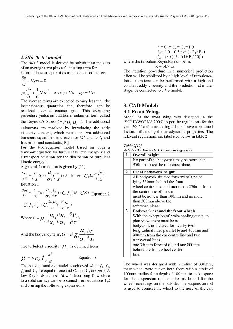
Each front aerofoil is made a main plane running
almost the whole width of the car suspended from
the nose. The flaps are usually made of one piece of
carbon fiber. On each end of the main plane there
are endplates.The end plates are 200mm. thick The
primary function of the end plate is to stop the high-
pressure air on the top of the wing from being
encouraged to roll over the end of the wing to the
low-pressure air beneath, causing induced drag.
Also, the design aim of the endplates is to
discourage the dirty air created by the front tire from
getting under the floor of the car.
Figure 1
If angled, the vane can generate more downforce as
air flows over the top surface more quickly than it
does over the lower surface. This gives the car
greater stability during cornering while reducing
straight line speed.[14]. The main aim is to deflect
the sir over the car as under the car the air faces a lot
of obstruction to it’s flow and can not be
smoothened to a greater accuracy compared to over
it.
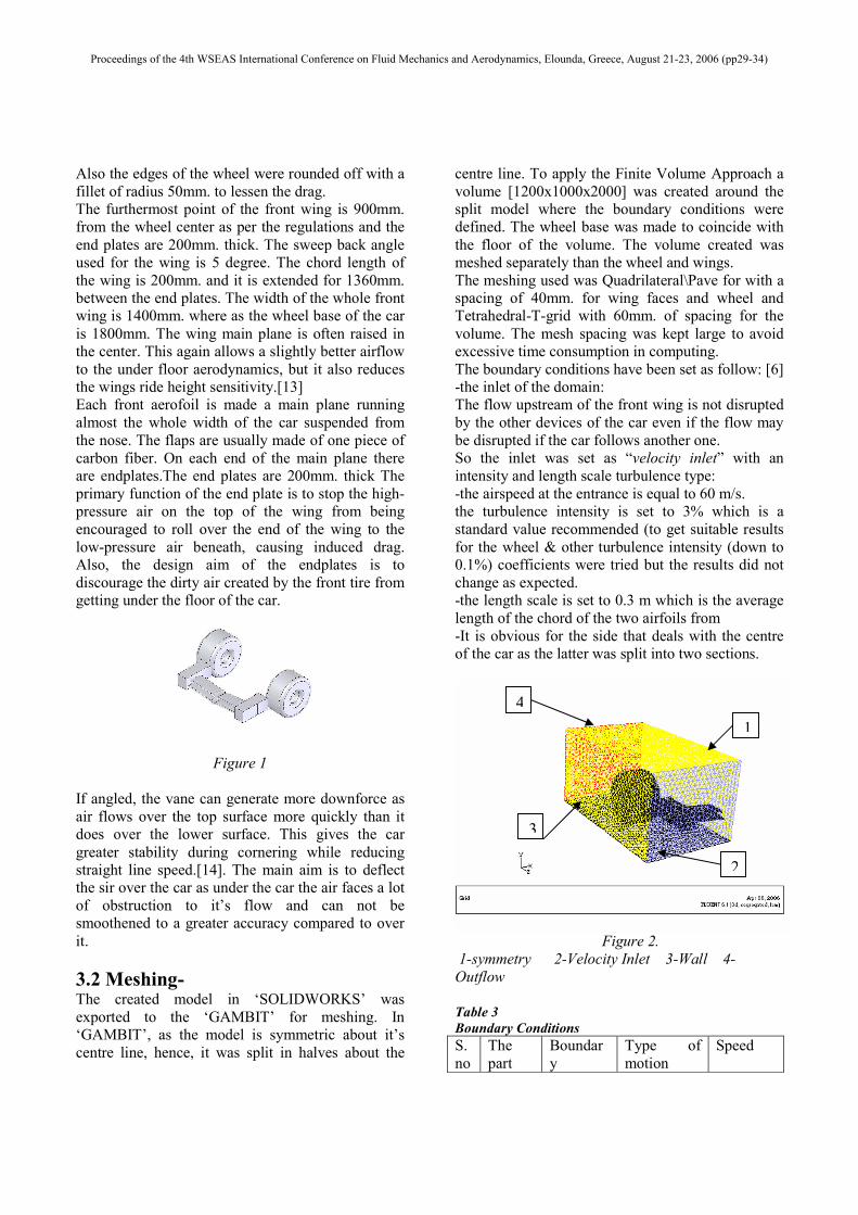
3.2 Meshing- The created model in ‘SOLIDWORKS’ was
exported to the ‘GAMBIT’ for meshing. In
‘GAMBIT’, as the model is symmetric about it’s
centre line, hence, it was split in halves about the
centre line. To apply the Finite Volume Approach a
volume [1200x1000x2000] was created around the
split model where the boundary conditions were
defined. The wheel base was made to coincide with
the floor of the volume. The volume created was
meshed separately than the wheel and wings.
The meshing used was Quadrilateral\Pave for with a
spacing of 40mm. for wing faces and wheel and
Tetrahedral-T-grid with 60mm. of spacing for the
volume. The mesh spacing was kept large to avoid
excessive time consumption in computing.
The boundary conditions have been set as follow: [6]
-the inlet of the domain:
The flow upstream of the front wing is not disrupted
by the other devices of the car even if the flow may
be disrupted if the car follows another one.
So the inlet was set as “velocity inlet” with an
intensity and length scale turbulence type:
-the airspeed at the entrance is equal to 60 m/s.
the turbulence intensity is set to 3% which is a
standard value recommended (to get suitable results
for the wheel & other turbulence intensity (down to
0.1%) coefficients were tried but the results did not
change as expected.
-the length scale is set to 0.3 m which is the average
length of the chord of the two airfoils from
-It is obvious for the side that deals with the centre
of the car as the latter was split into two sections.
Figure 2.
1-symmetry 2-Velocity Inlet 3-Wall 4-
Outflow
Table 3
Boundary Conditions
S.
no
The
part
Boundar
y
Type of
motion
Speed
1
2
3
4
Proceedings of the 4th WSEAS International Conference on Fluid Mechanics and Aerodynamics, Elounda, Greece, August 21-23, 2006 (pp29-34)

. condition
1. Front
wing
Stationar
y wall
None NA
2. Road Moving
wall
Translation
al
60m\s
3. Wheel Moving
wall
Rotational (
about it’s
axis)
181.82ra
d\s
4. Domai
n sides
Outflow NA NA
5. Car
centre
side
Symmetr
y
NA NA
As is clear from the boundary conditions, the real
problem was analyzed with the application of
relative motion. The moving objects in the actual
problem were set stationary and the stationary
objects were made moving wall (road and fluid).
The basic idea for setting the problem like that lies
in the fact that the relative motion between the two
remains the same as in the actual problem. In wind
tunnel testing, they use the same approach as defined
for the problem out here with the air being set at a
high velocity.
3.3 CFD SOLVER:-
The CFD solutions were carried out with Fluent 6.1.
The latter is a solver of the Navier-Stokes equations.
The remaining conditions for solving the problem
were defined in the solver.
The grid size was checked and the 811 faces
imported into FLUENT were smoothened and
swapped for covering the entire face and volume.
The transient component of the equation above was
solved using the explicit approach. A segregated
solver is used in such a method as the equations are
only solved as dependents of time. The convergence
criterion defined was of the order of 1e-03. For the
convection component, the SIMPLE algorithm was
used for restricting the computation time.
The file imported in the solver had 17760 nodes,
1530 mixed wall faces in zone 3, 2034 mixed wall
faces in zone 4, 1472 mixed wall faces in zone 5,
770 mixed outflow faces in zone 6, 768 mixed
velocity-inlet faces in zone 7, 4012 mixed symmetry
faces in zone 8, 174173 mixed interior faces in zone
10, 89733 tetrahedral cells in zone 2.
The Reynold’s number for this flow was calculated
to be between 106 and 3x10
6 [4]. So, the turbulent ‘k-
ε ’ model is selected as per the real conditions as it
is a three dimensional model and the flow can be
considered to a low Reynold’s number flow. The
CFD equations for the model have been shown in the
review. The fluid selected was air naturally, and was
set at a velocity of 60m/s in the direction opposite to
the direction of the road. The convergence criterion
and other force monitors were all defined with a
convergence criterion of 1e-03. The solution for all
the angles converged at 170 iterations.
4. Result:- Table 4
Angle of
attack
Co-
efficient of
lift(Cl)
Co-
efficient of
drag(Cd)
Ratio=
(Cl/Cd)
- 1 degree - 1.09 0.390 - 2.79
0 degree - 1.14 0.400 - 2.85
1 degree - 1.21 0.412 - 2.93
3 degree - 1.25 0.423 - 2.95
4 degree - 1.30 0.438 - 2.97
5 degree - 1.27 0.454 - 2.79
Figure 3. (Residuals plot)
-Cl/Cd
2.75
2.8
2.85
2.9
2.95
3
3.05
-2 0 2 4 6
Angle Of Attack
Fig. 4 (-CL/ CD v/s Angle of Attack)
Proceedings of the 4th WSEAS International Conference on Fluid Mechanics and Aerodynamics, Elounda, Greece, August 21-23, 2006 (pp29-34)
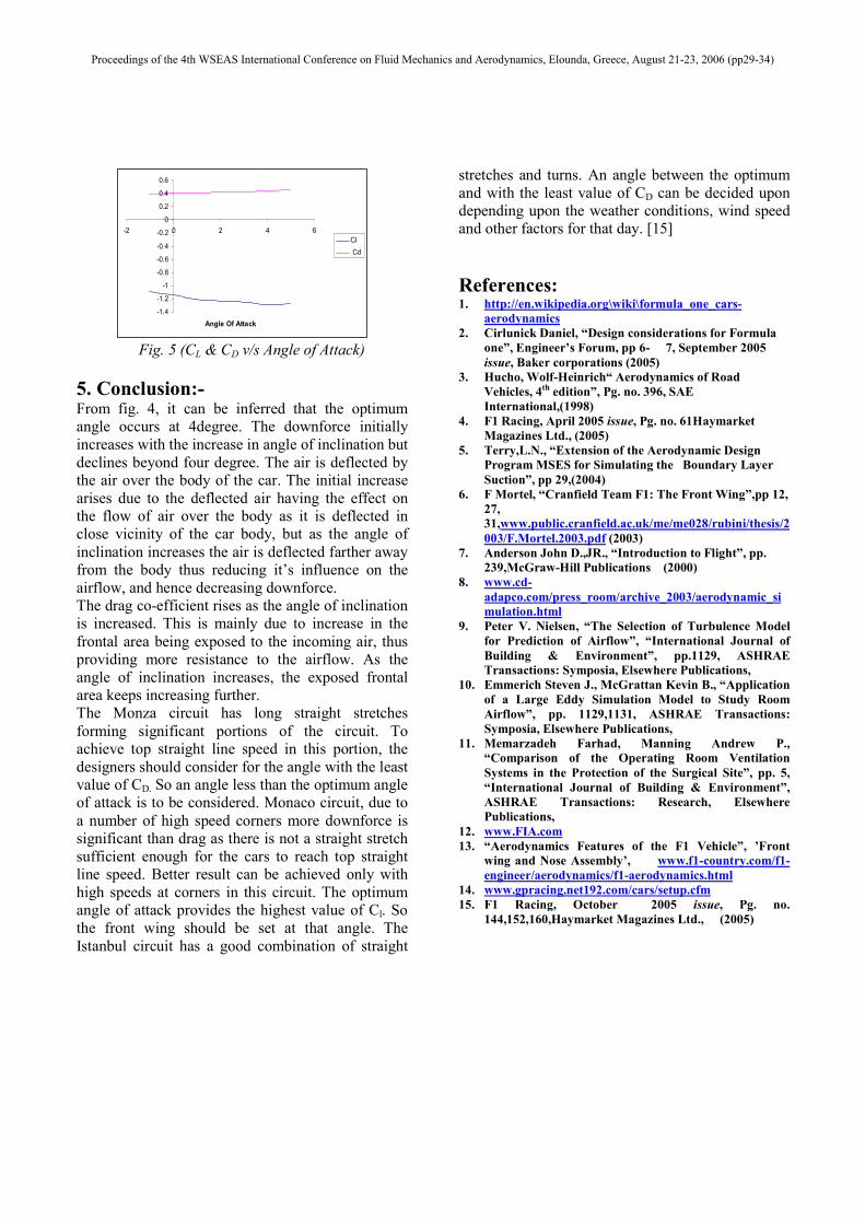
-1.4
-1.2
-1
-0.8
-0.6
-0.4
-0.2
0
0.2
0.4
0.6
-2 0 2 4 6
Angle Of Attack
Cl
Cd
Fig. 5 (CL & CD v/s Angle of Attack)
5. Conclusion:- From fig. 4, it can be inferred that the optimum
angle occurs at 4degree. The downforce initially
increases with the increase in angle of inclination but
declines beyond four degree. The air is deflected by
the air over the body of the car. The initial increase
arises due to the deflected air having the effect on
the flow of air over the body as it is deflected in
close vicinity of the car body, but as the angle of
inclination increases the air is deflected farther away
from the body thus reducing it’s influence on the
airflow, and hence decreasing downforce.
The drag co-efficient rises as the angle of inclination
is increased. This is mainly due to increase in the
frontal area being exposed to the incoming air, thus
providing more resistance to the airflow. As the
angle of inclination increases, the exposed frontal
area keeps increasing further.
The Monza circuit has long straight stretches
forming significant portions of the circuit. To
achieve top straight line speed in this portion, the
designers should consider for the angle with the least
value of CD. So an angle less than the optimum angle
of attack is to be considered. Monaco circuit, due to
a number of high speed corners more downforce is
significant than drag as there is not a straight stretch
sufficient enough for the cars to reach top straight
line speed. Better result can be achieved only with
high speeds at corners in this circuit. The optimum
angle of attack provides the highest value of Cl. So
the front wing should be set at that angle. The
Istanbul circuit has a good combination of straight
stretches and turns. An angle between the optimum
and with the least value of CD can be decided upon
depending upon the weather conditions, wind speed
and other factors for that day. [15]
References: 1. http://en.wikipedia.org\wiki\formula_one_cars-
aerodynamics
2. Cirlunick Daniel, “Design considerations for Formula
one”, Engineer’s Forum, pp 6- 7, September 2005
issue, Baker corporations (2005)
3. Hucho, Wolf-Heinrich“ Aerodynamics of Road
Vehicles, 4th edition”, Pg. no. 396, SAE
International,(1998)
4. F1 Racing, April 2005 issue, Pg. no. 61Haymarket
Magazines Ltd., (2005)
5. Terry,L.N., “Extension of the Aerodynamic Design
Program MSES for Simulating the Boundary Layer
Suction”, pp 29,(2004)
6. F Mortel, “Cranfield Team F1: The Front Wing”,pp 12,
27,
31,www.public.cranfield.ac.uk/me/me028/rubini/thesis/2
003/F.Mortel.2003.pdf (2003)
7. Anderson John D.,JR., “Introduction to Flight”, pp.
239,McGraw-Hill Publications (2000)
8. www.cd-
adapco.com/press_room/archive_2003/aerodynamic_si
mulation.html
9. Peter V. Nielsen, “The Selection of Turbulence Model
for Prediction of Airflow”, “International Journal of
Building & Environment”, pp.1129, ASHRAE
Transactions: Symposia, Elsewhere Publications,
10. Emmerich Steven J., McGrattan Kevin B., “Application
of a Large Eddy Simulation Model to Study Room
Airflow”, pp. 1129,1131, ASHRAE Transactions:
Symposia, Elsewhere Publications,
11. Memarzadeh Farhad, Manning Andrew P.,
“Comparison of the Operating Room Ventilation
Systems in the Protection of the Surgical Site”, pp. 5,
“International Journal of Building & Environment”,
ASHRAE Transactions: Research, Elsewhere
Publications,
12. www.FIA.com
13. “Aerodynamics Features of the F1 Vehicle”, ’Front wing and Nose Assembly’, www.f1-country.com/f1-
engineer/aerodynamics/f1-aerodynamics.html
14. www.gpracing.net192.com/cars/setup.cfm 15. F1 Racing, October 2005 issue, Pg. no.
144,152,160,Haymarket Magazines Ltd., (2005)
Proceedings of the 4th WSEAS International Conference on Fluid Mechanics and Aerodynamics, Elounda, Greece, August 21-23, 2006 (pp29-34)