Numerical Study for Optimum The stall Angle by Ansys Program
14
Numerical Study for Optimum The stall Angle by Ansys Program Qasim Nazim Zakat 1 , Zainul-aabideen Abdul-hakeem Ali 2 , Nawfel Muhammed Baqer Muhsin 3 , Hyder H. abd Balla 4 1,2 B. Sc ,Technical College of Najaf, Al-Furat Al-Awsat Technical University, Iraq. *3 Technical College of Najaf, Al-Furat Al-Awsat Technical University, Iraq,([email protected]). 4 Technical Institute of Najaf ,Al-Furat Al-Awast Technical University, Iraq. ABSTRACT This project aims to optimum the stall angle (which is the maximum angle possible that after it the wing/airfoil would experience stall) by making improvements or adding equipment to the structure of the wing, in this research we used an airfoil with section model NACA 0012 because this airfoil is symmetric in shape and there are other researches we used to reveal this project. There are several improvements to the wings, but not all of them are used to increase the stall angle. There are improvements or additions are used to increase the coefficient of lift and reducing the coefficient of drag like the flap but its important disadvantage that it is reducing the stall angle (important to note that the flap has many types and from them there are ones that increase the stall angle). In this project, we will study the effect of these three improvements: Backward facing step in the upper airfoil side (KFm – 2) .,Backward facing step in the lower airfoil side (KFm – 1 ) ., Suction system with various sucking .All these improvements have their way to increase the stall angle either by making vortex on the airfoil surface or by converting the turbulent airflow that happens when the stall is happening. All this will be discussed in later chapters of this project. Keywords: Airfoil, stall, vortex I. INTRODUCTION The airfoil shape was originally designed to produce lift, regardless of the separation, because the effort was made to make the airplane fly up. What encountered them was the stall, whenever the airflow around an airfoil separates, stall is said to have started[1-4]. There are two types of stall – figure (1-1), a and b – occurs over an airfoil: gradual and abrupt.The first type of stall is characterized by gradual stall followed by a shallow drop-off of the lift coefficient, this type frequently occurs on airfoils frequently occurs on airfoils with moderate or thick sections.The second type of stall is characterized by an abrupt drop-off of the section lift coefficient. It is often associated[5-7] with thin airfoil sections.If we want to understand the stall, we have to understand the separation, but first we have to know what the boundary layer is.The boundary layer is a layer of fluid close to a rigid body due to the Coandă effect, which makes the fluid attached to the rigid body when flowing over it.The separation occurs when the angle of attack increases[8-11], which makes the stagnation point moving to the lower side of the airfoil that make the maximum thickness is the front of the airfoil and the slope is so sharp that the Coandă effect will not occur, and this makes the separation point go upward until it reaches Journal of Xi'an University of Architecture & Technology Volume XII, Issue III, 2020 Issn No : 1006-7930 Page No: 2647
Transcript of Numerical Study for Optimum The stall Angle by Ansys Program

Numerical Study for Optimum The stall Angle
by Ansys Program
Qasim Nazim Zakat1 , Zainul-aabideen Abdul-hakeem Ali2 , Nawfel Muhammed Baqer Muhsin3 ,
Hyder H. abd Balla4
1,2B. Sc ,Technical College of Najaf, Al-Furat Al-Awsat Technical University, Iraq. *3Technical College of Najaf, Al-Furat Al-Awsat Technical University, Iraq,([email protected]).
4Technical Institute of Najaf ,Al-Furat Al-Awast Technical University, Iraq.
ABSTRACT
This project aims to optimum the stall angle (which is the maximum angle possible that after it
the wing/airfoil would experience stall) by making improvements or adding equipment to the
structure of the wing, in this research we used an airfoil with section model NACA 0012 because
this airfoil is symmetric in shape and there are other researches we used to reveal this project.
There are several improvements to the wings, but not all of them are used to increase the stall
angle. There are improvements or additions are used to increase the coefficient of lift and reducing
the coefficient of drag like the flap but its important disadvantage that it is reducing the stall angle
(important to note that the flap has many types and from them there are ones that increase the stall
angle). In this project, we will study the effect of these three improvements: Backward facing step
in the upper airfoil side (KFm – 2) .,Backward facing step in the lower airfoil side (KFm – 1) .,
Suction system with various sucking .All these improvements have their way to increase the stall
angle either by making vortex on the airfoil surface or by converting the turbulent airflow that
happens when the stall is happening. All this will be discussed in later chapters of this project.
Keywords: Airfoil, stall, vortex
I. INTRODUCTION
The airfoil shape was originally designed to
produce lift, regardless of the separation,
because the effort was made to make the
airplane fly up. What encountered them was
the stall, whenever the airflow around an
airfoil separates, stall is said to have
started[1-4]. There are two types of stall –
figure (1-1), a and b – occurs over an airfoil:
gradual and abrupt.The first type of stall is
characterized by gradual stall followed by a
shallow drop-off of the lift coefficient, this
type frequently occurs on airfoils frequently
occurs on airfoils with moderate or thick
sections.The second type of stall is
characterized by an abrupt drop-off of the
section lift coefficient. It is often
associated[5-7] with thin airfoil sections.If
we want to understand the stall, we have to
understand the separation, but first we have
to know what the boundary layer is.The
boundary layer is a layer of fluid close to a
rigid body due to the Coandă effect, which
makes the fluid attached to the rigid body
when flowing over it.The separation occurs
when the angle of attack increases[8-11],
which makes the stagnation point moving to
the lower side of the airfoil that make the
maximum thickness is the front of the airfoil
and the slope is so sharp that the Coandă
effect will not occur, and this makes the
separation point go upward until it reaches
Journal of Xi'an University of Architecture & Technology
Volume XII, Issue III, 2020
Issn No : 1006-7930
Page No: 2647

the frontal curve of the airfoil[12-18].
Boundary Layer Control For The
Prevention Of Separation
Various methods of flow-separation control
are used on aircraft and in other engineering
applications[19,20]. These methods be either
active or passive and we mean by that the
following.
The active method is require the expenditure
of additional power from the propulsion
units.
Some active techniques:-
1- Boundary-layer suction, figure(1-2)
2- tangential blower, figure(1-3)
The passive method is not requiring any
additional power; however, they usually lead
to increased drag at cruise when they are not
required.
Some passive techniques: -
1- Vortex generators
2- Wing fence
3- Saw-tooth leading edge
4- Leading-edge strake
5- Forward facing step (KFm family)
The Purpose From This Project
The purpose from this project is to study the
methods that make the separation latent and
the stall angle is increased, and to make a
good reference to the students ahead for
doing an advanced project for every single
method, other purpose is to show which
method is the best and more efficient in
doing this job of increasing the stall angle by
simulating each method in the same air and
flight conditions, and by using the same
airfoil NACA 0012. This project also
provide a cl-alpha for every method in every
positive angle of attack until after the stall
angle to make sure of the angle we presume,
that it is the stall angle indeed.
Figure (1-1), a
Figure (1-1), b
Figure (1-2), Separation
Journal of Xi'an University of Architecture & Technology
Volume XII, Issue III, 2020
Issn No : 1006-7930
Page No: 2648

Figure (1-3), Suction Method
Figure(1-4),a blown trailing-edge flap
Figure (1-5), passive techniques
Figure (1-6), passive techniques
(Backward facing step - upper side)
Figure (1-7), passive techniques
(Backward facing step - lower side)
II. PREVIOUS RESEARCHES
Preface
Taking into perspective that the methods
that we will discuss is relatively new.
Therefore, the researchers are not so many.
At this chapter, we will show a brief of these
researches, what is there importance, what is
there connection to our project and what is
the goal from this project.
Journal of Xi'an University of Architecture & Technology
Volume XII, Issue III, 2020
Issn No : 1006-7930
Page No: 2649

Researches Concerning Backward Facing
Step
The idea of making a backward facing step
on the surface of the airfoil was originally
made by Kline and Fogleman in 1972 which
they get from it a patent to their own glider
which they improve in it the lift force and
latent the separation phenomenon.In the year
1974, Top-flight laps followed by santich did
multiple of experiments on wings similar to
figure (2-1). At these experiments the
models was containing step not only in the
lower side like Kline and Fogleman's model
(KFm for short) but in the upper side as well.
The laminar flow in these types of models is
attaching closely to the outer radius of the
vortex that extend and shrink depending on
the pressure at the time.In the middle of the
1990's, NASA showed a concern again to the
(KFm), when Fertis presents an experimental
study on (New Airfoil Design Concept with
Improved Aerodynamics Characteristic).
The study gives a new design to the airfoil
section NACA 23012 and by the new design,
he proves that the airfoil with the backward
facing step has improved lift coefficient and
stall angle than the original NACA 23012.
The researcher did a flight tests to a
prototype with (2.134m) in length and
having a wing with the improved airfoil in a
speed of (12.2 – 79.25 m/s) and this was for
knowing the actual aerodynamic
performance and found the that it is
improved extremely with increasing the
flight speed.In the year 2006, the researcher
(Laith Ayad Salman) provides his
experimental and theoretical study (The flow
behavior and its effect on the aerodynamic
properties of the airfoil sections), in the
experimental part, he used four models of
steps, two in the upper side and two in the
lower side. He did the experiment on a wind
tunnel has a smoke blower to see the
vortices. The results came promising; the
four models gave a noticeable increase in the
lift coefficient and in the stall angle than the
original airfoil NACA 0015. In the
theoretical part, he used (Ansys 5.4), to
know the behavior of the flow on the surface
of the backward facing step and its effect on
the aerodynamic performance for the same
airfoil section, the results came with a
positive effect on the performance by
improved flow profile and a good increase in
the stall angle than the original stall angle
which is 12 deg.
Researches Concerning Boundary Layer
Suction
The earliest work on the boundary layer
suction was carried out in Germany and by
Ludwig prandtl and his papers on the
boundary layer theory during the late 1930s
by using wind tunnels. Research on suction-
type LFC continued up to the 1960s in Great
Britain and the United States, but owing to
the practical difficulties and to the relatively
low price of aviation fuel, boundary layer
suction researches was discontinued in the
late 1960's. More recently, with the
advanced technologies, the researchers are
back to this concept.In the year 2010, H.J.B.
van de Wal presented a thesis with the name
(Design of a Wing with Boundary Layer
Suction). In this thesis, he presented a new
design of an airfoil BW 10–144 to be his
wing cross section with a flap and aileron
22% of the cord and the suction holes
beginning in 75% of the cord. Thesis was
theoretical and he used (XFOIL) program.
He noticed a good improvement with
aerodynamic properties and a raise in the
stall angle and the maximum lift coefficient.
This Project And Its Relation To The
Previous Researches
After taking the knowledge from reading
previous researches, it is obvious that all the
researches concentrated on one method of
improving the aerodynamic performance and
increasing the stall. While in this research,
our goal is to study different methods and
more important is to compare between them
to see which one of them is the more
efficient by simulating the original airfoil
section NACA 0012 in (ANSYS 16)
program and exert the values of the
coefficient of lift and drag. After that, we
took four models of modifications to the
Journal of Xi'an University of Architecture & Technology
Volume XII, Issue III, 2020
Issn No : 1006-7930
Page No: 2650

original airfoil and they are:-
1- Airfoil with backward facing step of
(Lu=0.5C, Du=0.5T) in the upper
side.
2- Airfoil with backward facing step of
(Lu=0.5C, Du=0.5T) in the lower
side
3- Airfoil with suction system (capacity
of suction is 0.03U∞).
4- Airfoil with suction system (capacity
of suction is 0.1U∞).
We did a simulation on these models to
make a reliable chart of cl – α; therefore, the
simulation was to the models from there αcl=0
until after the stall angle with two degrees to
clarify the stall angle of each modified
model. In this project, we succeeded to
make a limit on the suction capacity needed
to make the airfoil overcome the regular stall
angle.
Figure(2-1),Vortex on backward facing
step airfoil
Figure(2-2), suction on H.J.B. van
de Wal's model
AIRFOIL’S NEW METHODS
Preface
In this chapter we will talk about the new
methods we studied and there effect on the
stall angle and take into consideration the
environmental conditions would be the same
for all of them, for us to compare between
them.
Upper Backward Facing Step (KFm- 2)
This modification is considerably improved
by air drones amateurs who made a whole
family from it. This modification is done by
taking a cut from the upper side of the airfoil
with known length and thickness and the
limitation of it is tacking into consideration.
From [1] we found that the best cut which
gives a relatively high stall angle is Lu= 0.5
C and Du=0.5 T. The way of this method
making improvements on the airfoil is by
making a circulation beneath the step,
making the stream to deflect back from its
separating state. Another way of
understanding this is by knowing that the
circulation pressure is less than the stream
pressure (like making a vacuum pressure)
which make the separating stream pulled
down again making it laminar. From figures
3-1 and 3-2 we will distinguish the
difference between the flow with and
without the backward facing step, notice that
the angle in the two conditions is 12 degrees,
which is the original stall angle.
Journal of Xi'an University of Architecture & Technology
Volume XII, Issue III, 2020
Issn No : 1006-7930
Page No: 2651
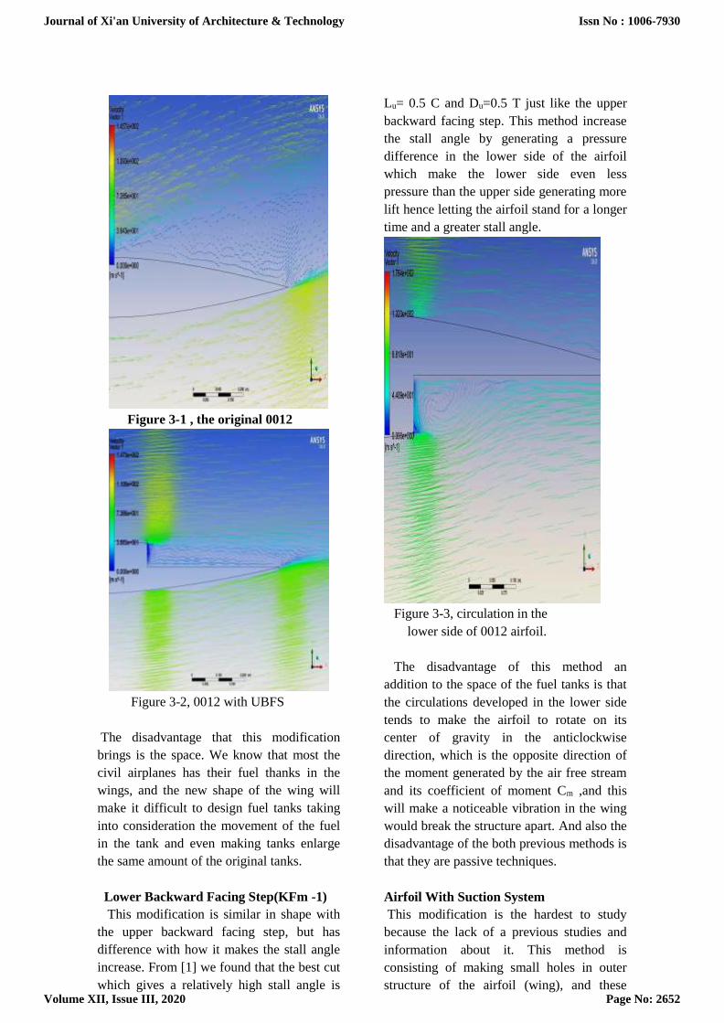
Figure 3-1 , the original 0012
Figure 3-2, 0012 with UBFS
The disadvantage that this modification
brings is the space. We know that most the
civil airplanes has their fuel thanks in the
wings, and the new shape of the wing will
make it difficult to design fuel tanks taking
into consideration the movement of the fuel
in the tank and even making tanks enlarge
the same amount of the original tanks.
Lower Backward Facing Step(KFm -1)
This modification is similar in shape with
the upper backward facing step, but has
difference with how it makes the stall angle
increase. From [1] we found that the best cut
which gives a relatively high stall angle is
Lu= 0.5 C and Du=0.5 T just like the upper
backward facing step. This method increase
the stall angle by generating a pressure
difference in the lower side of the airfoil
which make the lower side even less
pressure than the upper side generating more
lift hence letting the airfoil stand for a longer
time and a greater stall angle.
Figure 3-3, circulation in the
lower side of 0012 airfoil.
The disadvantage of this method an
addition to the space of the fuel tanks is that
the circulations developed in the lower side
tends to make the airfoil to rotate on its
center of gravity in the anticlockwise
direction, which is the opposite direction of
the moment generated by the air free stream
and its coefficient of moment Cm ,and this
will make a noticeable vibration in the wing
would break the structure apart. And also the
disadvantage of the both previous methods is
that they are passive techniques.
Airfoil With Suction System
This modification is the hardest to study
because the lack of a previous studies and
information about it. This method is
consisting of making small holes in outer
structure of the airfoil (wing), and these
Journal of Xi'an University of Architecture & Technology
Volume XII, Issue III, 2020
Issn No : 1006-7930
Page No: 2652

holes is connected to tubes leading to a
system generates a vacuum pressure sucking
from the air stream. This method helps
remaking the turbulent flow be a laminar
flow, by proper suction method, the air flow
will reattach with the surface again
preventing the separation from happening.
In this method, we studied two suction
velocities to show the difference if the
suction velocity changed, and they are, 3
percent of the air stream velocity and 10
percent of the air stream velocity. The results
were tremendously different in the stall
angle and the lift produced.
The advantage of this method over the
previous ones is that this method is an active
technique.
Figure 3-4, 3% suction.
Figure 3-5, 10% suction.
However, there are disadvantages for this
method, which is It will take a noticeable
space from the wing interior and it will add
to the weight of the airplane furthermore, the
minimum suction velocity needed for this
method to work is very high. The last
disadvantage limit the use of this method to
the low speed airplanes (like the private
airplanes).
III. ANALYSIS BY USING
ANSYS WORCKBENCH
Ansys develops and markets finite element
analysis software used to simulate
engineering problems. The software creates
simulated computer models of structures,
electronics, or machine components to
simulate strength, toughness, elasticity,
temperature distribution, electromagnetism,
fluid flow, and other attributes. Ansys is
used to determine how a product will
function with different specifications,
without building test products or conducting
crash tests. For example, Ansys software
may simulate how a bridge will hold up after
years of traffic. In this chapter, we will walk
through the procedure of the analysis and the
specifications using ansys workbench (fluid
flow [fluent]).
Specifications
Here we will talk about the specifications
we took and why. First, we have to say that
all the analysis was considering
aerodynamics and not the structure.
Therefore, there is no mentioning about the
type of the material or the increase/decrease
in deflection occurs during every method
used. The analysis is two-dimensional
because we considered the modifications that
can be analyzed in 2D and not be affected if
we neglect the depth of it.
To make sure that the results we give is
eligible; we build up our base case according
to the data we take from [2] for the
coefficient of lift to NACA 0012.
Journal of Xi'an University of Architecture & Technology
Volume XII, Issue III, 2020
Issn No : 1006-7930
Page No: 2653

We used a method called C-mesh method
(Figure 4-1)
figure 4-1, c-mesh method
This method is common in aerospace
analysis because it makes a good approach to
the real wind tunnel test and by making the
walls far enough from the airfoil. The
dimensions of the geometry is as following,
the radius of the curve has to be 12.5 of the
cord and the distance from the trailing edge
to the outlet has to be 12.5 of cord. The
advantage of this method is to make the
mesh in a more organized way, which make
the iteration in the coming steps faster with
the same number of elements.The number of
elements in the analysis is 400000 elements
with minimum size of 0.0017 m, and with
the use of refinement and sizing tools to
make the elements smaller at the walls of the
airfoil. Now we'll talk about the
environmental specifications and we made it
non-dimensional as much as we can. The
pressure and temperature used is the ambient
that is 101.3 KPa and 15 C respectively, the
air mach number is 0.258, the Reynolds
number is 6e+6
From figure 4-2 we can see that the inlet
include all the walls except for one which is
the outlet
figure 4-2, inlet, outlet and airfoil
The reason why we make this is to make it
easier to change the angle of attack by
changing the flow angle instead of changing
the angle of the airfoil itself every time,
changing the airfoil every time make us
change the geometry and thus generating the
mesh every time and that's a time consuming
procedure. Instead, we can change the flow
angle hence the angle of attack by changing
the velocity specification method from
normal to components and insert the x and y
components. (See figure 4-3 a and b)
figure 4-3 a, zero angle of attack
Journal of Xi'an University of Architecture & Technology
Volume XII, Issue III, 2020
Issn No : 1006-7930
Page No: 2654

figure 4-3 b, 2 degrees angle of attack
The solver type we chose is pressure-based
type because we have subsonic compressible
flow, we know that from the mach number
and we are using air as a material [3]. It’s a
steady flow and the velocity formulation to
be absolute.
From [4] and [5] we'll know that the
best flow model for our case is SST k- 𝜔,
and it's governed by the equations:-
(4.1)
(4.2)
Note that the procedure for all the methods is
almost the same.
Finally, we ran the calculation for the
iteration, which took between 2300 to 3000
iterations and a time of 47 to 61 minutes per
convergence.
figure 4-4, design modular window
figure 4-5, mesh window
Journal of Xi'an University of Architecture & Technology
Volume XII, Issue III, 2020
Issn No : 1006-7930
Page No: 2655

figure 4-6, setup window
figure 4-7, solution window
RESULTS and DISCUSION
Preface
In this chapter, we'll show the charts of the
coefficient of lift to make the stall angle
clear for each method and then compare
them to make a conclusion of which method
is best and why.
First, we have to make clear how to get
the lift coefficient from fluent. In the
solution window we'll go to the reports and
then select the forces and select the right
direction vector as illustrated in the figure 5-
1, from this figure we will know that the
direction of the lift is always perpendicular
to the flow direction, we have to keep that in
mind because we are altering the flow NOT
the airfoil.
figure 5-1, lift and drag direction
figure 5-2, showing lift coefficient
5-2 Results
The base case we got very accurate results,
comparing it to the data we take from [2].
We saw that the error was not exceeding
Journal of Xi'an University of Architecture & Technology
Volume XII, Issue III, 2020
Issn No : 1006-7930
Page No: 2656

0.1% and figure 5-3 illustrate that.
figure5-3,theoretical and experimental
results
Upper Backward Facing Step
The KFm-2 shows good improvements in lift
and angle wise. It showed an increase in the
stall angle by the third, rising up from 12
degrees to 18 degrees and a maximum lift
coefficient increase by 45%, rising up from
1.03 to 1.489.
figure5-4,experimental and kfm-2
Lower Backward Facing Step
The KFm-1 has good improvements too
but not like KFm-2. It shows an increase in
the stalling angle by 17%, rising up from 12
degrees to 14 degrees and a maximum lift
coefficient increase by 40%, rising up from
1.03 to 1.447.
figure5-5,experimental and kfm-1
Figure5-6,KFm-2 and KFm-1
Suction
3% suction had its share from
improvements with 17% increase of stall
angle, rising up from 12 to 14 degrees and a
maximum lift coefficient increase by 24%,
rising up from 1.03 to 1.28.
0
0.2
0.4
0.6
0.8
1
1.2
0 10 20 30
CO
FF. O
F LI
FT
ANGLE
tyeoretical experimental
-0.4
-0.2
0
0.2
0.4
0.6
0.8
1
1.2
1.4
1.6
1.8
0 10 20 30
CO
FF. O
F LI
FT
ANGLE
experimental upper
0
0.2
0.4
0.6
0.8
1
1.2
1.4
1.6
0 10 20 30
CO
FF. O
F LI
FT
ANGLE
experimental lowar
-0.4
-0.2
0
0.2
0.4
0.6
0.8
1
1.2
1.4
1.6
1.8
0 10 20 30
CO
FF. O
F LE
FT
ANGLE
upper lowar
Journal of Xi'an University of Architecture & Technology
Volume XII, Issue III, 2020
Issn No : 1006-7930
Page No: 2657

figure5-7,experimental and 3% suction
However, the 10% suction showed better
characteristics than the 3% suction with
improvements in both the lift coefficient and
the stall angle. It showed an increase by the
third in terms of stall angle, rising up from
12 to 16 degrees. The 10% suction have a
very good rise in terms of the maximum lift,
which is by 61% from 1.03 to 1.661.
figure5-8,experimental and 10%suction
figure5-9, 3% suction and 10% suction
Comparison and Conclusion
From 5-2 we will see that if we consider
just the stall angle, then the best method is
the upper backward facing step, which has a
stall angle of 18 degrees. However, if we
consider the maximum lift produced, then
we have to consider using the 10% suction
which has a maximum lift of 1.661. It
actually depends on what we care the most.
figure5-10, comparison
-0.2
0
0.2
0.4
0.6
0.8
1
1.2
1.4
0 10 20 30
CO
FF. O
F LE
FT
ANGLE
suction 3 % experimental
0
0.2
0.4
0.6
0.8
1
1.2
1.4
1.6
1.8
0 10 20 30
CO
FF. O
F LI
FT
ANGLE
suction 10 % experimental
-0.2
0
0.2
0.4
0.6
0.8
1
1.2
1.4
1.6
1.8
0 10 20 30
CO
FF. O
F LI
FT
ANGLE
suction 3 % suction 10 %
-0.5
0
0.5
1
1.5
2
0 10 20 30
CO
FF. O
F LI
FT
ANGLE
suction 3 % suction 10 %
tyeoretical experimental
upper lowar
Journal of Xi'an University of Architecture & Technology
Volume XII, Issue III, 2020
Issn No : 1006-7930
Page No: 2658

In our opinion, we prefer the upper
backward facing step for the reasons below:-
1. The method is passive which means it
doesn't add further installments into the
airplane.
2. The method has a fair maximum lift of
1.489.
3. The method has the best stall angle
among the other methods mentioned
earlier which is 18 degrees.
The disadvantages this modification brings is
the decreasing of the space of the tanks and
this can be overcome by adding extra fuel
tank in the fuselage with pump system
connecting with it. The other disadvantage is
the decrease in the strength of the structure
by cutting a fair amount of it, and this also
can overcome by using tougher materials or
increasing the rips and the stringers.
Conclusions
We don't have recommendations
considering the methods. The only
recommendation we want to give is to
encourage one of the groups that will come
after us to make a project that is the same as
ours but experimentally by using the wind
tunnel we have in the aerodynamics lab and
compare the results they will get, wishing for
them all the best.
REFERENCES
[1]. H. Ashley, G. Zartarian, Piston theory – a new aerodynamic tool for the aeroelastician, J.
Aeronaut. Sci. 23 (1956) 1109–1118.
[2]. Q.S. Bi, P. Yu, Symbolic computation of normal forms for semi-simple cases, J. Comput.
Appl. Math. 102 (1999) 195–220.
[3] B.D. Coller, P.A. Chamara, Structural non-linearities and the nature of the classic flutter
instability, J. Sound Vib. 277 (2004) 711–739.
[4]. Q. Ding, J.E. Cooper, A.Y.T. Leung, Hopf bifurcation analysis of a rotor/seal system, J.
Sound Vib. 252 (5) (2002) 817–833.
[5]. Q. Ding, J.E. Cooper, A.Y.T. Leung, Application of an improved cell mapping method to
bilinear stiffness aeroelastic systems, J. Fluid Structure 20 (1) (2005) 35–49.
[6] S.H. Kim, I. Lee, Aeroelastic analysis of a flexible airfoil with a freeplay non-linearity, J.
Sound Vib. 193 (5) (1996) 823–846.
[7]. L. Librescu, G. Chiocchia, P. Marzocca, Implications of cubic physical/aerodynamic non-
linearities on the character of the flutter instability boundary, Int. J. Non-Linear Mech. 38
(2003) 173–199.
[8]. L. Liu, Y.S. Wong, B.H.K. Lee, Application of the centre manifold theory in non-linear
aeroelasticity, J. Sound Vib. 234 (4) (2000) 641–659. [9]. L. Liu, Y.S. Wong, B.H.K. Lee, Non-
linear aeroelastic analysis using the point transformation method, Part 1: free-play model, J.
Sound Vib. 253 (2) (2002) 447–469.
Journal of Xi'an University of Architecture & Technology
Volume XII, Issue III, 2020
Issn No : 1006-7930
Page No: 2659
[10]. L. Liu, Y.S. Wong, B.H.K. Lee, Non-linear aeroelastic analysis using the point
transformation method, Part 2: hysteresis model, J. Sound Vib. 253 (2) (2002) 471–483.
[11]. J.K. Liu, L.C. Zhao, Bifurcation analysis of airfoils in incompressible flow, J. Sound Vib.
154 (1991) 117–124.
[12]. Mustafa T. Mohammed Alhashimi, Nawfel Muhammed Baqer Muhsin , Mustafa T M A,
Nawfel M B M., 2019. Treatment of (Electric Wires and Machines)-Erosion via Engineering
Materials by the Coating., NeuroQuantology,17,11,11-16., 10.14704/nq.2019. 17.11.NQ19108.
[12]. S.J. Price, B.H.K. Lee, H. Alighanbari, An analysis of the post-instability behavior of a
two-dimensional airfoil with a structural non-linearity, J. Aircraft 31 (6) (1994) 1395–1401.
[13]. P. Shahrzad, M. Mahzoon, Limit cycle flutter of airfoils in steady and unsteady flows, J.
Sound Vib. 256 (2) (2002) 213–225.
[14]. S.N. Singh, M. Brenner, Limit cycle oscillation and orbital stability in aeroelastic systems
with torsional non-linearity, Nonlinear Dynamics 23 (2003) 435–450.
[15]. Y.R. Yang, KBM Method of analyzing limit cycle flutter of a wing with an external store
and comparison with wind tunnel test, J. Sound Vib. 187 (1995) 271–280.
[16]. L.C. Zhao, Z.C. Yang, Chaotic motions of an airfoil with non-linear stiffness in
incompressible flow, J. Sound Vib. 138(1990)245–254.
[17]. Nawfel Muhammed Baqer ,Nawfel M B M. M.Sc Thesis in Mechanical
Engineering. College of Engineering University of Basrah; 2014.
[18]. Nawfel Muhammed Baqer Muhsin, Nawfel M B .Hydrod ynamic and thermal
flows of fluids, Chem Proc Eng Res. 2015; 32: 22–35p.
Journal of Xi'an University of Architecture & Technology
Volume XII, Issue III, 2020
Issn No : 1006-7930
Page No: 2660


![14 Stall Parallel Operation [Kompatibilitätsmodus] · PDF filePiston Effect Axial Fans (none stall-free) Stall operation likely for none stall-free fans due to piston ... Stall &](https://static.fdocuments.us/doc/165x107/5a9dccd97f8b9abd0a8d46cf/14-stall-parallel-operation-kompatibilittsmodus-effect-axial-fans-none-stall-free.jpg)