Finalprojectreportg2 141218075116 Conversion Gate01
52
RAJIV GANDHI PRODYOGIKI VISHWAVIDYALAYA BHOPAL-462036 NRI INSTITUTE OF INFORMATION SCIENCE &TECHNOLOGY, BHOPAL DEPARTMENT OF CIVIL ENGINEERING SESSION 2014-2015 PROJECT REPORT ON “DESIGN OF MULTISTORY BUILDING PROVIDING RESIDENCE FOR INDUSTRIAL AND COMMERCIAL PURPOSE” GUIDED BY: Prof. Sandeep K Shrivastava Department of Civil Engineering NIIST, Bhopal SUBMITTED BY:- Priyanshu Suryawanshi (0115CE11103 Nilesh kumar Patel (0115CE111026) Sraddhanand Meshram (0115CE111049) Suresh Chakrawarti (0115CE111057) Suraj Mishra (0115CE111056) 1
description
co
Transcript of Finalprojectreportg2 141218075116 Conversion Gate01

1
RAJIV GANDHI PRODYOGIKI VISHWAVIDYALAYABHOPAL-462036
NRI INSTITUTE OF INFORMATION SCIENCE &TECHNOLOGY, BHOPAL
DEPARTMENT OF CIVIL ENGINEERINGSESSION 2014-2015
PROJECT REPORT ON“DESIGN OF MULTISTORY BUILDING PROVIDING RESIDENCE
FOR INDUSTRIAL AND COMMERCIAL PURPOSE”
GUIDED BY:Prof. Sandeep K ShrivastavaDepartment of Civil EngineeringNIIST, Bhopal
SUBMITTED BY:-Priyanshu Suryawanshi (0115CE111030)Nilesh kumar Patel (0115CE111026)Sraddhanand Meshram (0115CE111049)Suresh Chakrawarti (0115CE111057)Suraj Mishra (0115CE111056)

2
DECLARATION
We hereby declare that the work which is being presented in the project report entitled “DESIGN OF MULTISTOREY
BUILDING PROVIDING RESIDENCE FOR INDUSTRIAL AND COMMERCIAL PURPOSE”
in the partial fulfillment of Bachelor of Engineering in Civil Engineering is an authentic record of our own work carried
out under the guidance of Prof. Sandeep K Shrivastava. The work has been carried out
at NIIST, Bhopal.The matter embodied in the report has not been submitted
for the award of any other degree or diploma.
The matter embodied in the report has not been submitted for the award of any other degree or diploma.

3
NRI INSTITUTE OF INFORMATION SCIENCE &TECHNOLOGY(AFFL. BY RAJIV GANDHI PRODYOGIKI VISHWAVIDYALAYA)
BHOPAL
DEPARTMENT OF CIVIL ENGINEERINGSESSION 2014-2015
CERTIFICATE This is to certify that Suraj Mishra, Suresh Chakrawarti, Nilesh Kumar Patel, Sraddhanand Meshram, Priyanshu Suryawanshi, students of Fourth year (VII semester) Bachelor of Civil Engineering, NIIST have successfully completed their Major Project Report on “Design of Multistory Building”.We approve the project for the submission for the partial fulfillment of the requirement for the award of degree in Civil Engineering.
Mr. J.P. Nanda Prof. Sandeep K ShrivastavaH.O.D. Project Head Department of Civil Engineering Department of Civil Engineering

4
AKNOWLEDGEMENT We would like to express our deep sense of gratitude to our respected and learned guide Prof. Sandeep K Shrivastava for his valuable guidance. We are also thankful for his timely encouragement given in completing the project.We are also grateful to respected Mr. J.P. Nanda, HOD (Department of Civil Engineering) NIIST, Bhopal for permitting us to utilize all the necessary facilities of the institution.We would like to thank Dr. S.C.Kapoor, Director NIIST for his valuable encouragement and approval for the project.We are also thankful to all other staff members of our department for their kind co-operation and help.Lastly, we would like to express our deep appreciation towards our classmates and family members for providing us the much needed kind support and encouragement.
Thank You

5
Sr. No. Topic Page no.
1. Introductioni). Effective Span ii). Stiffnessiii). Loadsiv). Analysis
6
2. Load Distribution 11
3. Moment Calculation by KANI’S Method
14
4. Design of One way Slab 19
5. Design of Two way Slab 25
6. Design of T-Beam 32
7. Design of Column 37
8. Design of Staircase 40
9. Design of Flat Footing 46
10. Conclusion 51
11. References 52
Table of Contents

6
Multistory Building
1.1. INTRODUCTION
The aim of this project is to design a Multistory Building (G+2) for residential purpose, taking earthquake load into consideration.Multistory buildings are very commonly seen in cities. Construction of such tall buildings are possible only by going to a set of rigidly interconnected beams and column. These rigidly interconnected beams and columns of multi bay and multistoried are called Buildings frames. To avoid long distance of travel, cities are growing vertically rather than horizontally. In other words multistory buildings are preferred in cities.Building laws of many cities permits construction of ground plus three storey buildings without lifts.
The loads from walls and beams are transformed to beams, rotation of beams take place. Since, beams are rigidly connected to column, the rotation of column also take place. Thus any load applied any where on beam is shared by entire network of beam and columns.
7
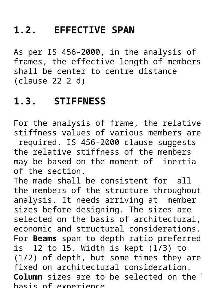
1.2. EFFECTIVE SPAN
As per IS 456-2000, in the analysis of frames, the effective length of members shall be center to centre distance (clause 22.2 d)
1.3. STIFFNESS
For the analysis of frame, the relative stiffness values of various members are required. IS 456-2000 clause suggests the relative stiffness of the members may be based on the moment of inertia of the section. The made shall be consistent for all the members of the structure throughout analysis. It needs arriving at member sizes before designing. The sizes are selected on the basis of architectural, economic and structural considerations.For Beams span to depth ratio preferred is 12 to 15. Width is kept (1/3) to (1/2) of depth, but some times they are fixed on architectural consideration.Column sizes are to be selected on the basis of experience.

8
It is to be noted that in Multistory frames, columns of upper stories carry less axial force but more moments, while columns of lower storey carry more axial loads and less moments.Design can roughly estimate the axial load on lower storey column and arrive at sizes of the column.Next two to three stories can have same size. Beyond that, sizes may be reduced. Stiffness of member is given by (I/L).
1.4. LOADS
For Multistory frames Dead load, imposed load (live load), wind load and earthquake loads are important for designing.The IS code suggests following load combination to get designed loads: 1. 1.5DL + 1.5IL 2. 1.5DL + 1.5WL 3. 1.5DL + 1.5EL 4. 1.2DL + IL + 1.2WL 5. 1.2DL + IL + 1.2EL

9
1.5 ANALYSIS
It may be analyzed as a set of intersecting frames taking care of loads from triangular pattern of loads from floors. However, IS 456-2000 (Clause 22.42) permits the analysis of frames by approximate methods like:Portal method, cantilever method, Substitute frame method for Dead loads, factor method for wind loads; to arrive at design moments, shear and other forces.We have adopted KANI’S method for frame analysis.

10TYPICAL FLOOR PLAN
N

11
Load due to slab: (KN)A = 13.79+13.79+10.575+10.575 = 48.73 B = 13.76+13.79 = 27.58 C = A = 48.73D = 13.79+10.575+8.44+4.22 = 37.025 E = 13.79+8.44+4.22+4.11+2.93 = 33.49 F = 13.79+10.575+2.93+4.11 = 31.405G = 4.22+8.44 = 12.66 H = 4.22+8.44+4.11+2.93 = 19.70 I = 4.11+2.93 = 7.07Load due to slab: (KN)A = 2.25 B = 2.25+3 = 5.25 C = 3 D = 3.375 E = 3.375+1.875 = 5.25 F = 1.875G =3.375 H =6.675 I =3.375
Fig1. Triangular Pattern of load distribution.
12
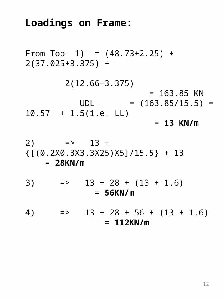
Loadings on Frame:
From Top- 1) = (48.73+2.25) + 2(37.025+3.375) + 2(12.66+3.375) = 163.85 KN UDL = (163.85/15.5) = 10.57 + 1.5(i.e. LL) = 13 KN/m
2) => 13 + {[(0.2X0.3X3.3X25)X5]/15.5} + 13 = 28KN/m
3) => 13 + 28 + (13 + 1.6) = 56KN/m
4) => 13 + 28 + 56 + (13 + 1.6) = 112KN/m

13
Fig. LOADED FRAME
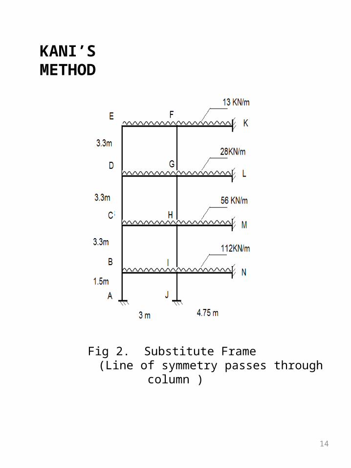
Fig 2. Substitute Frame (Line of symmetry passes through column )
KANI’S METHOD
14

15
Fixed End moments: (KMm)
Moment of Inertia:
2 2112 384
8 8210.58
42
21
9.75
BI IB
IN NI
CH HC
DG GD
EF FE
wlMf Mf
Mf Mf
Mf Mf
Mf Mf
Mf Mf
105.3
52.65
24.44
HM MH
GL LG
FK KF
Mf Mf
Mf Mf
Mf Mf
3 34 40.2 0.3
2 1012 12
bdI m

Rotation Factors:Joint Member Stiffness R.Stiffness R.F.
BA 2I/1.5 -0.26
B BI 2I/3 86I/33 -0.12
BC 2I/3.3 -0.12
CB 2I/3.3 -0.16
C CH 2I/3 62I/33 -0.18
CD 2I/3.3 -0.16
DC 2I/3.3 -0.16
D DG 2I/3 62I/33 -0.18
DE 2I/3.3 -0.16
E ED 2I/3.3 14I/11 -0.24
EF 2I/3 -0.26
IJ 2I1.5 -0.22
I IN 2I/4.75 1898I/627 -0.07
IH 2I/3.3 -0.10
IB 2I/3 -0.11
16

17
Joint Member Stiffness R.Stiffness R.F.
HI 2I/3.3 -0.13H HM 2I/4.75 1442I/627 -0.10
HG 2I/3.3 -0.13HC 2I/3 -0.14GH 2I/3.3 -0.13
G GL 2I/4.75 1442I/627 -0.10
GF 2I/3.3 -0.13GD 2I/3 -0.14FG 2I/3.3 -0.18
F FK 2I/4.75 354I/206 -0.12
FE 2I/3 -0.20
Rotation Factors:
18
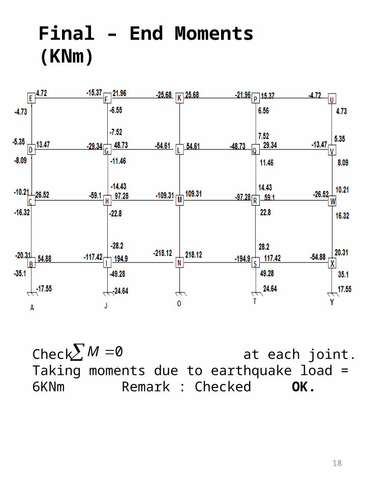
Final – End Moments (KNm)
Check at each joint. Taking moments due to earthquake load = 6KNm Remark : Checked OK.
0M
19
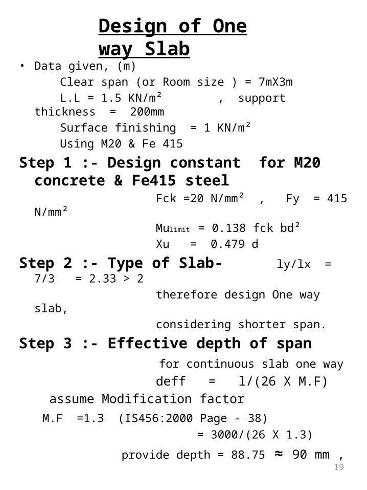
• Data given‚ (m) Clear span (or Room size ) = 7mX3m L.L = 1.5 KN/m² , support thickness = 200mm Surface finishing = 1 KN/m² Using M20 & Fe 415
Step 1 :- Design constant for M20 concrete & Fe415 steel
Fck =20 N/mm² , Fy = 415 N/mm² Mulimit = 0.138 fck bd² Xu = 0.479 d
Step 2 :- Type of Slab- ly/lx = 7/3 = 2.33 > 2 therefore design One way slab, considering shorter span.
Step 3 :- Effective depth of span for continuous slab one way
deff = l/(26 X M.F) assume Modification factor M.F =1.3 (IS456:2000 Page -
38) = 3000/(26 X 1.3)
provide depth = 88.75 ≈ 90 mm ,
Design of One way Slab

20
Take deff = 125 mmOverall depth D = d +(c.c+Ø/2) assume dia. of bar 10mm = 125 +(20+10/2) c.c= 20mm = 125+25 =150 mm
Fig. Diagrammatic Representation
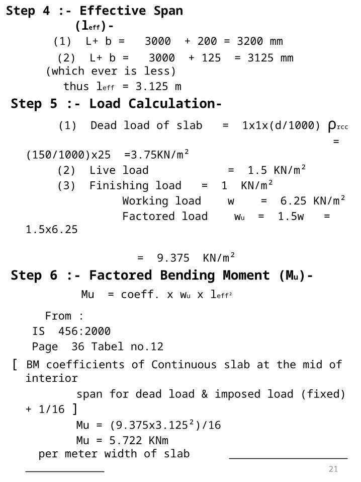
Step 4 :- Effective Span (leff)-
(1) L+ b = 3000 + 200 = 3200 mm (2) L+ b = 3000 + 125 = 3125 mm (which ever is
less) thus leff = 3.125 m
Step 5 :- Load Calculation-
(1) Dead load of slab = 1x1x(d/1000) ρrcc
= (150/1000)x25 =3.75KN/m² (2) Live load = 1.5 KN/m² (3) Finishing load = 1 KN/m² Working load w = 6.25 KN/m² Factored load wu = 1.5w = 1.5x6.25 = 9.375 KN/m²
Step 6 :- Factored Bending Moment (Mu)- Mu = coeff. x wu x leff²
From : IS 456:2000 Page 36 Tabel no.12
[ BM coefficients of Continuous slab at the mid of interior
span for dead load & imposed load (fixed) + 1/16 ] Mu = (9.375x3.125²)/16 Mu = 5.722 KNm per meter width of
slab 21
22
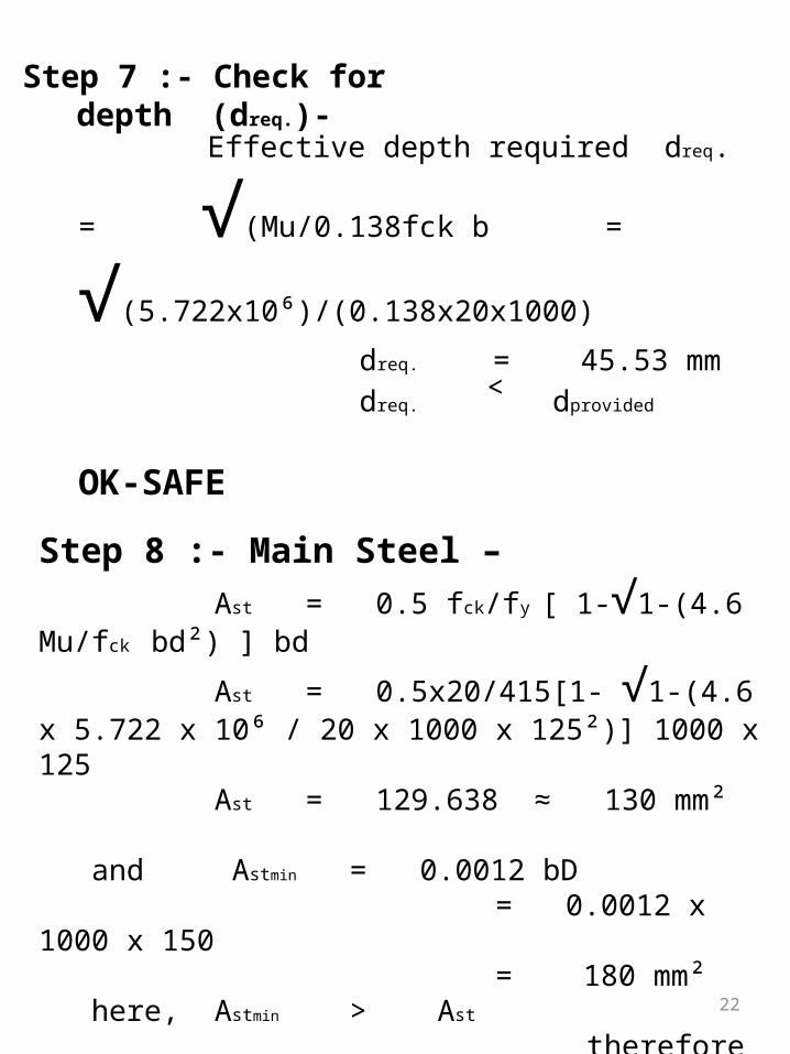
Step 7 :- Check for depth (dreq.)-
Effective depth required dreq. = √(Mu/0.138fck b=
√(5.722x10⁶)/(0.138x20x1000)
dreq. = 45.53 mm dreq. ˂ dprovided
OK-SAFE
Step 8 :- Main Steel – Ast = 0.5 fck/fy [ 1-√1-(4.6 Mu/fck bd²) ] bd
Ast = 0.5x20/415[1- √1-(4.6 x 5.722 x 10⁶ / 20 x 1000 x 125²)] 1000 x 125 Ast = 129.638 ≈ 130 mm²
and Astmin = 0.0012 bD = 0.0012 x 1000 x 150 = 180 mm² here, Astmin > Ast
therefore use Astmin i.e. 180 mm²
23
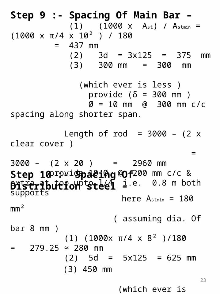
Step 9 :- Spacing Of Main Bar – (1) (1000 x Ast) / Astmin = (1000 x π/4 x 10² ) / 180
= 437 mm (2) 3d = 3x125 = 375 mm (3) 300 mm = 300 mm (which ever is less ) provide (δ = 300 mm ) Ø = 10 mm @ 300 mm c/c spacing along shorter span.
Length of rod = 3000 – (2 x clear cover ) = 3000 – (2 x 20 ) = 2960 mm provide 10 Ø @ 200 mm c/c & extra at top upto l/4 i.e. 0.8 m both supports
Step 10 :- Spacing Of Distribution steel – here Astmin = 180 mm² ( assuming dia. Of bar 8 mm ) (1) (1000x π/4 x 8² )/180 = 279.25 ≈ 280 mm (2) 5d = 5x125 = 625 mm (3) 450 mm (which ever is less ) provide 8 mm dia. Of distribution bar @ 280 mm c/c spacing across main bar

24
Fig. Reinforcement Details in One way Slab.

25
Design of Two way Slab
Given Data-Size of slab (m) = 7 x 4.75Live load = 2 KN/m²support thickness = 200 mmFinishing = 1 KN/m²
Use M20 & Fe415 Step 1):- Design constant-
fck = 20 MPa, fy = 415 MPaMu lim = 0.138 fck bd²Xu = 0.479 d
Step 2):- Type of Slab-ly/lx = 7/4.75 = 1.5 < 2
(Two way slab)Step 3):- Deffx = lx/26 x 1.5 = 4750/26 x 1.5 = 121.7 mm = dx
≈ 125 mm = dx
Assume 10 Ø, clear cover 20 mmdy = 125-10 = 115 mmOverall depth of slab D = d+(c.c.+ Ø/2)
D = 125 + 20 + 5 = 150 mm

26
Step 4):- Effective length of Slabhere support thickness = 200 mm
Shorter Span Longer Span
i). Clear span + dx 4750 + 125=4875mm
i). Clear span + dy 7000 + 115=7115mm
ii). Clr span + support width 4750 + 200=4950mm
ii). Clear span + b 7000 + 200=7200mm
(which ever is less)lx = 4.875 m ly = 7.115 m
Step 5):- Load-i). D.L. = 1x1x150/1000x25 = 3.75KN/m²ii). Live load = 2KN/m²iii). Finishing = 1KN/m²
Working load = 6.75KN/m²Wu = 1.5 x 6.75 = 10.125KN/m²
Step 6):- Moments- ly/lx = 7.115/4.875 = 1.46

27
ly/lx αx αy
1.4 0.099 0.051
1.46
1.5 0.104 0.046
αx = 0.099 + (0.104-0.099)/(1.5-1.4) x (1.46-1.4) = 0.102αy = 0.051 + (0.046-0.05)/(1.5-1.4) x (1.46-1.4) = 0.048
Mx = αx Wu lx² = 0.102x10.125x4.875² = 24.54 KNmMy = αy Wu ly² = 0.048x10.125x4.875² = 11.55 KNm
Step 7:-Check for depth-drequired = √(Mx/0.138x20x1000) = √[(24.54x10⁶)/(0.138x20x1000)] = 94.29 mm ≈ 95 mmdreq < dprovided
OK SAFE.
Moment coefficients:
28
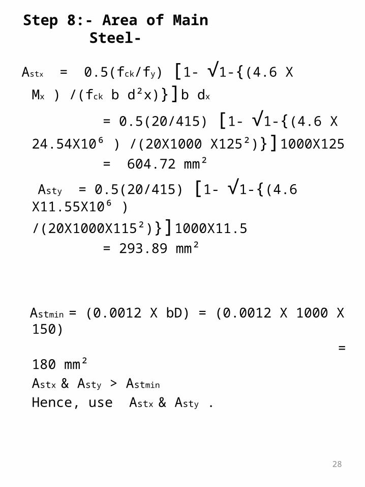
Step 8:- Area of Main Steel-
Astx = 0.5(fck/fy) [1- √1-{(4.6 X Mx ) /(fck b d²x)}]b dx
= 0.5(20/415) [1- √1-{(4.6 X 24.54X10⁶ ) /(20X1000
X125²)}]1000X125 = 604.72 mm²
Asty = 0.5(20/415) [1- √1-{(4.6 X11.55X10⁶ )
/(20X1000X115²)}]1000X11.5 = 293.89 mm²
Astmin = (0.0012 X bD) = (0.0012 X 1000 X 150) = 180 mm²
Astx & Asty > Astmin
Hence, use Astx & Asty .

29
Step 10:- Spacing of main bar -
assume dia. of main bar Ø = 10 mm
Shorter span Long span
(1) 1000 X π/4 X 10²/ Astx = 129.88 ≈ 120 mm
(1) 1000 X π/4 X 10²/ 293.89 = 267.24 ≈ 260 mm
(2) 3dx = 3 X 12 = 375 (2) 3dy = 3 X 115 = 345
(3) 300 mm (3) 300 mm
(which ever is less)provide 10 Ø @ 120 c/c provide 10 @ 260 c/c (3/4 l ) span middle strip

30
Step 11:- Distribution Steel - Astmin = 180 mm² spacing assume Ø = 8 mm (1) 1000 X π/4 X 8²/180 =279.25 mm (2) 5dx = 5X125 = 625 5dy = 5X 115 = 575 (3) 450 mm provide 8 Ø @ 270 c/c edge strip (span/ 8)
Step 12:- Check for deflection – dprovided = l/(26 X MF) Astprovided = (1000 X π/4 X 10²)/120 = 654.5 mm² Astrequired = 604.72 mm² % of steel = Astprovided /(b X d X 1000) = 0.37 % F5 = 0.58 X fy Astrequired/ Astprovided
F5 = 222.4 IS 456 : 2000 MF = 1.5 drequired 121.8 mm dprovided 125 mm
drequired ˂ dprovided OK-SAFE

Fig. Reinforcement Details in Two way Slab.
31

32
Design of T- BEAM
Data :Clear span(L) = 4.75 m, fck = 20 Depth of flange (Df) = 150 mm, fy = 415 Depth of web (bw) = 200 mmImposed Load = 112 KN/m,
Step-1 Effective Depth (d):
Adopt D = 320 + 20 + 25 = 360 mm
Step-2 Effective Span (leff):
The least of(i) Centre to centre of support = 4.75+0.2 = 4.95 m(ii) Clear span + effective depth = 4.75 + 0.32 = 5.1 m Effective span = 4.95 m
Step-3 LoadsImposed load = 112 KN/mUltimate load = 1.5 X 112 = 168 KN/m
2/N mm
2/N mm
4750316.67 320
15 15eff
spand mm mm
33
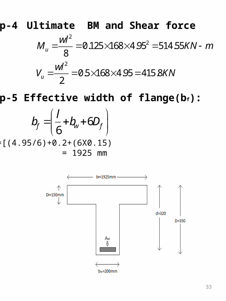
Step-4 Ultimate BM and Shear force
Step-5 Effective width of flange(bf):
=[(4.95/6)+0.2+(6X0.15) = 1925 mm
22
2
0.125 168 4.95 514.558
0.5 168 4.95 415.82
u
u
wlM KN m
wlV KN
66f w f
lb b D
34
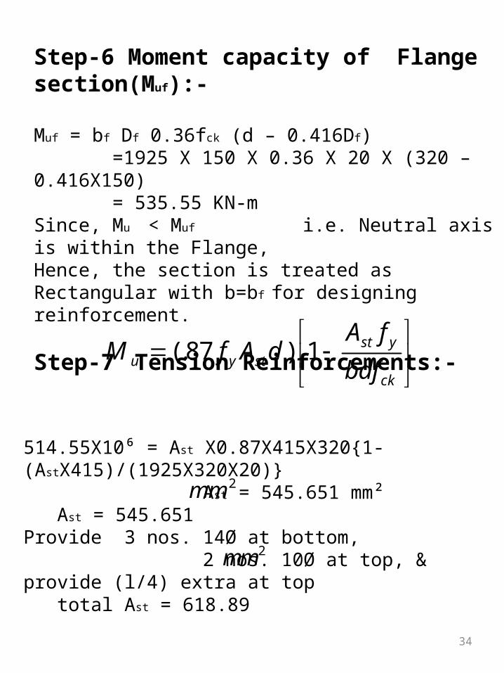
Step-6 Moment capacity of Flange section(Muf):-
Muf = bf Df 0.36fck (d – 0.416Df) =1925 X 150 X 0.36 X 20 X (320 – 0.416X150) = 535.55 KN-mSince, Mu < Muf i.e. Neutral axis is within the Flange,Hence, the section is treated as Rectangular with b=bf for designing reinforcement.
Step-7 Tension Reinforcements:-
(.87 ) 1 st yu y st
ck
A fM f A d
bdf
514.55X10⁶ = Ast X0.87X415X320{1-(AstX415)/(1925X320X20)} Ast = 545.651 mm²
Ast = 545.651 Provide 3 nos. 14Ø at bottom, 2 nos. 10Ø at top, & provide (l/4) extra at top
total Ast = 618.89
2mm
2mm

35
Step-8 Shear Reinforcement:- τv = (Vu / bw d) = 415.8X10³/(200X320) = 6.49 N/mm² Pt = 100 Ast /bwd = 100X545.651/(200X320) = 0.853 m from IS 456:2000, page no.73,table-19, Design shear strength of concrete (M20) τc = 0.28 N/mm²
Balance Shear => Vus = [Vus – (τc bd)] Vus = [415.8 – (0.28X200X320 )10¯³] = 397.88 KN
Using 8 mm dia, 2 legged stirupps, Spacing is given by,
SV = (0.87fy Asv d/Vus)
SV = (0.87X415 X(π÷4)X8²/397.88X10³) Sv = 220 mm ≈ 200 mm
provide spacing of 100 mm and gradually increase to200 mm at centre of span

36
Step9:- Check for deflection Control – Pt = 100 Ast/(bf d) = (100 X 5378 )/( 2025 X 320 ) = 0.83 bw/bf = 200/2025 = 0.099 (L/d)provided = L/d x Kt x Kc x Kf 4950/320 = 20x1.05x1x0.94 15.46 ˂ 19.74 hence, check for deflection is satisfactory.
Fig. Reinforcement Details in T-beam.
37
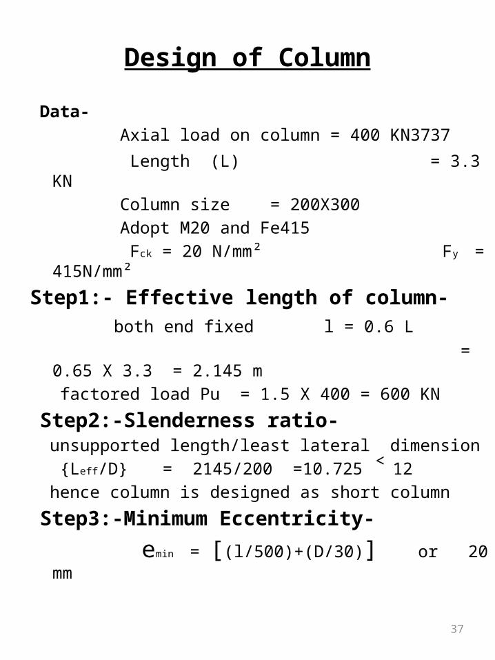
Design of Column
Data- Axial load on column = 400 KN3737 Length (L) = 3.3 KN Column size = 200X300 Adopt M20 and Fe415 Fck = 20 N/mm² Fy = 415N/mm²
Step1:- Effective length of column- both end fixed l = 0.6 L = 0.65 X 3.3 = 2.145 m factored load Pu = 1.5 X 400 = 600 KN
Step2:-Slenderness ratio- unsupported length/least lateral dimension {Leff/D} = 2145/200 =10.725 ˂ 12 hence column is designed as short column
Step3:-Minimum Eccentricity-
emin = [(l/500)+(D/30)] or 20 mm
38
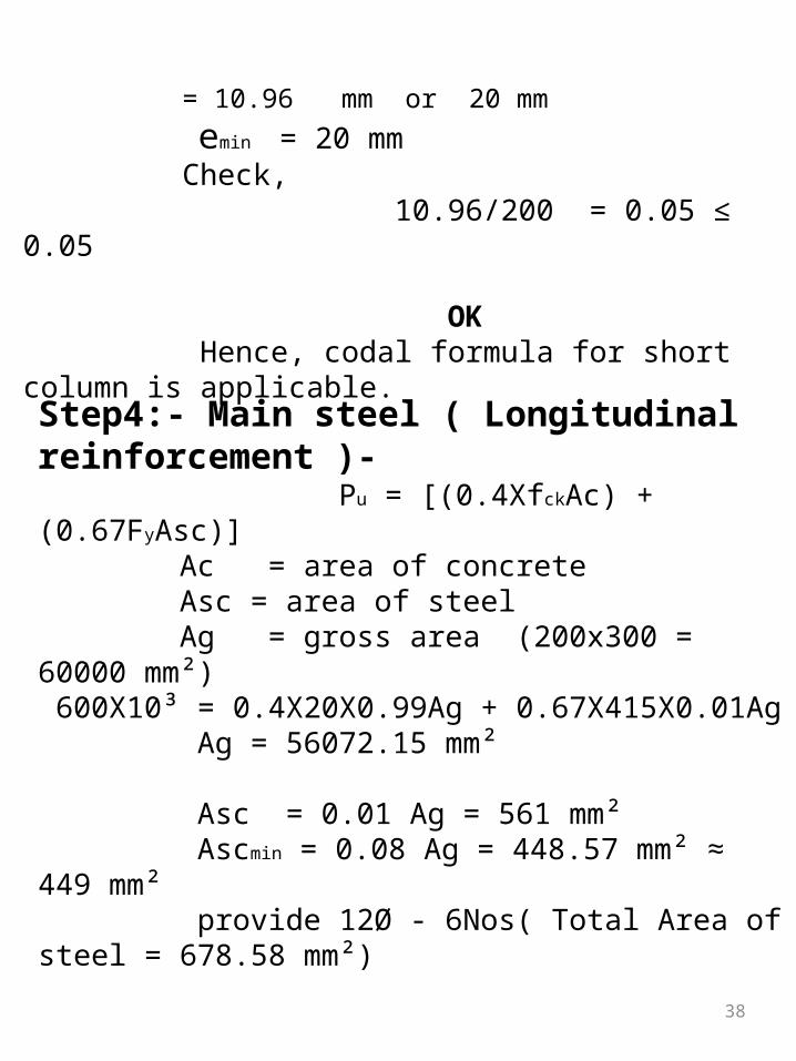
= 10.96 mm or 20 mm
emin = 20 mm Check, 10.96/200 = 0.05 ≤ 0.05 OK Hence, codal formula for short column is applicable.
Step4:- Main steel ( Longitudinal reinforcement )- Pu = [(0.4XfckAc) + (0.67FyAsc)] Ac = area of concrete Asc = area of steel Ag = gross area (200x300 = 60000 mm²) 600X10³ = 0.4X20X0.99Ag + 0.67X415X0.01Ag Ag = 56072.15 mm² Asc = 0.01 Ag = 561 mm² Ascmin = 0.08 Ag = 448.57 mm² ≈ 449 mm² provide 12Ø - 6Nos( Total Area of steel = 678.58 mm²)

39
Step5:- Design of Lateral Ties- (1) Dia. of ties Øtie = Øtie / 4 =12/4 = 3 mm
Øtie = 8 mm (for Fe 415)Spacing- a) least lateral dimension = 200 mm b) 16 X Ømain = 16X12= 192 mm c) 300 mm which ever is less provide 8 Ø @ 200c/c

40
Design of Stair case (Dog legged)Data, ht. Of storey = 3.3 m size of stair hall =4.5mX3m L.L = 2 KN/m² supported width = 200 mm
Step 1 :- Design constants – using M20 and fe415 Fck = 20 Mpa Fy = 415 Mpa Mulimit = 0.138 Fckbd²
Step 2 :- Arrangement of stair-Ht. Of storey = 3.3 mHt. Of flight = 3.3/2 = 1.65 massume R = 150 mm , T = 300 mmNo. Or riser = 1650/150 = 11No. Of tread = 11-1 = 10Going G = no. Of tread X T
= 10 X 300 = 3000 mm

41
Fig. Arrangement of Steps in Staircase.

42
Step 3 :- Effective length- leff = c/c dist. b/w support = 3000 + 1500 +200/2 = 4600 mm
Step 4 :- Effective depth of waist slab – d ≈ l/25 = 4600/25 = 184 ≈ 180 assume 10 Ø and clear cover 15 mm D = 180 + ( 15+10/2) = 200 mm but we adopted D = 150 mm
Step 5 :- Load calculation (unit area ) –
(1) Self wt. Of waist slab in horizontal area
= w s X √(R²+T²)/T
= (1X1XD/1000)ρrcc X √(150²+300²)/300= 4.19 KN/m²
43
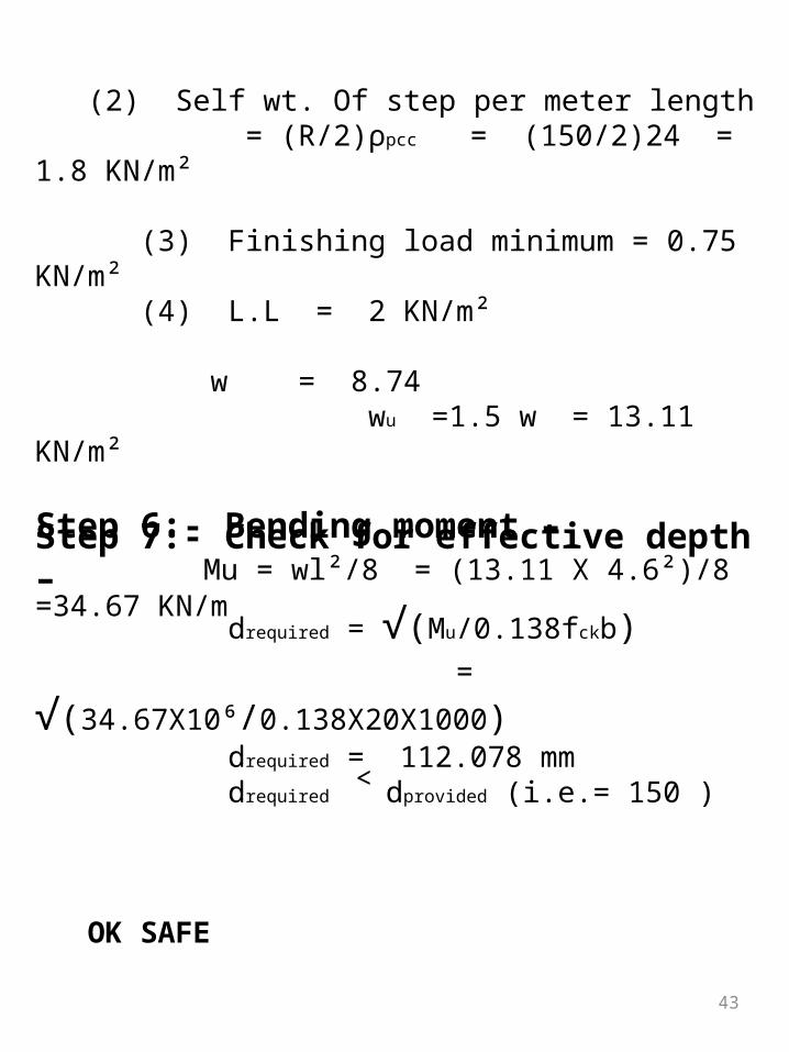
(2) Self wt. Of step per meter length = (R/2)ρpcc = (150/2)24 = 1.8 KN/m² (3) Finishing load minimum = 0.75 KN/m² (4) L.L = 2 KN/m²
w = 8.74 wu =1.5 w = 13.11 KN/m²
Step 6:- Bending moment – Mu = wl²/8 = (13.11 X 4.6²)/8 =34.67 KN/m
Step 7:- Check for effective depth – drequired = √(Mu/0.138fckb) = √(34.67X10⁶/0.138X20X1000) drequired = 112.078 mm drequired ˂ dprovided (i.e.= 150 ) OK SAFE

44
Step 8:- Main steel – Ast =
0.5X20/415[1-√1-{(4.6X34.67X10⁶)/(20X1000X150²)}] ≈ 711 mm² Astmin = 0.0012X1000X150 = 180 mm² use Ast = 711 mm²
Step 9:- Spacing of Main bar- (1) (1000Xπ/4X10²)/711 assume 10Ø =110.46 mm (2) 3X150 (3) 300mm which ever is less Main bar provide 10Ø @ 100 c/c
Step 10:- Distribution bar- use Astmin = 180 assume Ø = 8 mm (1) (1000X π/4X8²)/180 = 279.15 mm (2) 5D = 5X150 =750 mm (3) 450 mm distribution bar provide 8Ø @ 250 c/c spacing

45
Fig. Reinforcement Details in Stairs

46
Design of Flat Footing
Data:Assume SBC of soil = 200 KN/m²Reinforcement concrete column size = 200 X 300Axial service load P = 400 KNAdopt M20 & Fe415
Step 1: Calculation of Load-a) Load on column = 400KNb) Self wt. of footing = 10% of column = 400 X (10/100) = 40 KN Total load = 440 KN Factored load Wu = 1.5 X 440 = 660 KN
Step 2: Area of footing-
2( ) 4402.2
200
Load withoutfactorm
SBCofSoil

47
Assuming square footing,Size of footing = Adopt size of footing = 1.5m X 1.5m
Step 3: Net upward pressure-
Step 4: Bending Moment calculation-Maximum bending moment will be on the face of column, M = F X Distance of C.G. = (area X stress) x (0.65/2) = 92.95 KNmStep 5: Depth of Footing –
2.2 1.45m
2660293.33 /
1.5 1.5u
FactoredLoadPn KN m
actualAreaofFooting X
6
0.138
92.95 10410.35 420
0.138 20 200
requiredck
required
Md
f b
Xd mm Adopt mm
X X

48
Assume cover = 60mmThus, Overall Depth = 420+60 = 480mm
Step 6: Main Steel calculation-
Provide 10Ø @ 100 c/c in each direction at bottom of footing i.e. 12 nos .
min
min
min
2
6
2
2
2
2
4.60.5 1 1
20 4.6 92.95 100.5 1 1 1500 420415 20 1500 420
623.18
0.0012
0.0012 1500 480 864
, 864
ck ust
y ck
st
st
st
st
st
f MA Bd
f f Bd
X XA X
X X
A mm
A BD
A mm
Use A mm

49
Step 7: Check for Shear-The critical; section will be at a distance (d/2) from column face. Shear Force = Stress X Area = 293.33X{ 1.5²-[(0.200+0.420) X (0.300+0.420)] } = 529.05 KN
Shear stress
Permisible shear stress
OK SAFE.
2 2, [ ( ) ]here Area B b d
0
2
2
529.05
1 0.420
1260 /
0.00126 /
v
v
v
v
V
b d
KN m
N mm
0, 2( ) 2(0.2 0.3) 1here b perimetre l b m
0.25
0.25 20
1.11
ck
c
f

50
Fig. Sectional View
Fig. Plan

51
CONCLUSION
In this report, a design of Multistory building for residential purpose is presented. We have
successfully completed the planning and designing of a multistory (G+2) structure.
The main key features of project are as follows: Plot size = 20m X 20m Total construction area = 65% of plot size. Total no. of 1BHK Flats = 12
52
References
A.K. Jain, Advanced R.C.C. Design. N. Krishna Raju, Reinforced Concrete Design. S.S. Bhavikatti, Advanced R.C.C. Design. IS 456-2000 IS 1893(Part 1) 2002 IS 800-2007