
Final Report
71
Page | 1 A REPORT ON Fireball Formation And Combustion of Coal in Boiler By: Tarun Dogra 2013A4PS299P Animesh Okhade 2013B3A1575G Shah Zalak 2013A4PS251P At Adani Power Maharashtra Limited, Tirora A Practice School-I station of Birla Institute of Technology & Science, Pilani June/July 2015
-
Upload
zalak-shah -
Category
Documents
-
view
342 -
download
0
Transcript of Final Report

Page | 1
A REPORT
ON
Fireball Formation
And
Combustion of Coal in Boiler
By:
Tarun Dogra 2013A4PS299P
Animesh Okhade 2013B3A1575G
Shah Zalak 2013A4PS251P
At
Adani Power Maharashtra Limited, Tirora
A Practice School-I station of
Birla Institute of Technology & Science, Pilani
June/July 2015

Page | 2
A REPORT
ON
Fireball Formation
And
Combustion of Coal in Boiler
By:
Tarun Dogra 2013A4PS299P
Animesh Okhade 2013B3A1575G
Shah Zalak 2013A4PS251P
Prepared in fulfilment of the
Practice School-I Course No.
BITS F221
At
Adani Power Maharashtra Limited, Tirora
A Practice School-I station of
Birla Institute of Technology & Science, Pilani
June/July 2015

Page | 3
1. Acknowledgement
We would like to express our sincere gratitude to our College, Birla Institute
of Technology and Science for conducting Practice school–I which gives
industrial experience and Adani power for giving me this opportunity to visit
the plant and prepare a report. I would like to thank our PS-1 instructor, Mr.
Abhijit Asati sir for his guidance and support. Also we would like to thank our
co-instructor Mr. Vishal Parwani for his support.
We would like to thank our station head, Mr C P Sahoo sir and Dy. General
Manager (Technical training), Dr. Vijay V Gandhewar and Asst. Manager
(Technical training), Mr Sanjay Kr. Kajuri for their immense efforts made for
us to learn about a Thermal power plant.
We would also like to thank Mr. Pritish Pandey and all other senior engineers
who were our mentors during plant visits for teaching us in spite of their busy
schedule.
Place: Adani Power, Tirora
Date: July 12, 2015

Page | 4
BIRLA INTITUTE OF TECHNOLOGY & SCIENCE PILANI (RAJASTHAN)
Practice School Division
Station: Adani Power Maharashtra Limited, Tirora Centre: Nagpur/Tirora
Duration: From: 22 May 2015 to: 16 July 2015
Date of Submission: 12 July 2015
Title of the Project: Fireball Formation and Combustion of Coal in Boiler
ID No. Names of Students
2013A4PS299P Tarun Dogra
2013B3A1575G Animesh Okhade
2013A4PS251P Shah Zalak
Name of the PS Faculty: Dr. Abhijit Asati
Key Words: Combustion, Pulverisation, Burners, Firing, Excess Air, Furnace.
Project Area: Fireball Formation and Combustion of Coal in Boiler
Abstract: This report gives an overview of combustion process and its
optimisation, at Adani Power Maharashtra Ltd., Tirora.
Tarun Dogra
Animesh Okhade
Shah Zalak Dr. Abhijit Asati
Signature of Students Signature of PS Faculty
Date: July 12, 2015 Date: July 12, 2015

Page | 5
3. Table of Contents Title Page 1. Acknowledgement 3 2. Abstract 4 3. Table of contents 5 4. Introduction 7 5. Combustion 8
5.1. Principles of combustion 8 5.2. Combustion Reactions 10 5.3. Significance of various elements of coal 10 5.4. Coal Analysis in Tirora 11 5.5. Excess Air 11 5.6. 3T’s of Combustion 13 5.7. Pulverization 14 5.8. Reasons for improper Combustion 14 5.9. Combustion generated Pollutants 15 5.10. Need for Combustion Optimization 17
6. Combustion Analysis 17 6.1. Why perform Combustion Analysis 18 6.2. What’s measured? 19 6.3. Measurement Tools 24 6.4. Using the Measurements 25
7. Fuel Firing System 29 7.1. Introduction 29 7.2. Characteristics of Ideal Firing System 29 7.3. Firing System Concepts 30 7.4. Comparison of single and Multiflame concepts 30 7.5. Methods of Fuel Firing 32 7.6. Components of Fuel Firing System 37 7.7. Oil Firing System 50
8. Boiler 53 9. Furnace 55 10. Burners 58 11. Improving Boiler Efficiency 61 12. Methods for lowering NOX and CO levels 66 13. Conclusion 70 14. References 71

Page | 6
List of Figures
Title Page 1. Combustion Efficiency vs Excess Air 12 2. Boiler Heat Losses 18 3. Excess Air Supplied 20 4. Too little combustion causes CO to form 21 5. Combustion gas concentrations 22 6. Flue temperature vs efficiency 23 7. Combustion Efficiency vs Excess Air 26 8. Vertical Firing System 32 9. Wall Firing Burner 34 10. Burner for wall firing 34 11. Eddy Plate Ignitor arrangement 39 12. Eddy plate Ignitor 39 13. I.F.M. Ignitor 41 14. H.E.A. Ignitor 42 15. Re-circulating pattern in H.E.A. Ignition system 43 16. Concentric and Parallel Oil Gun 44 17. Mechanical/Pressure Atomiser 46 18. Internal Mixing Atomiser 47 19. Boiler Block Diagram 55 20. Comparison of furnaces for different fuels 57 21. Effect of excess air on efficiency 65 22. Concept of in-flame NOx reduction 66 23. The structure of HT-NR3 Burner 67 24. NOx performance of HT-NR Series 68 25. Concept of new TSC System 79
List of Tables
1. Coal Specifications in Adani Power, Tirora 11 2. Possible savings per year with a
5% improvement in boiler efficiency 19 3. LDO parameters 50 4. HFO parameters 51

Page | 7
4. Introduction
A thermal power station works on the basic principle that heat liberated by burning fuel is converted into mechanical work by means of a suitable working fluid. The mechanical work is converted into electrical energy by means Of generator. In a steam power station, heat is realized by burning fuel, this heat is taken by water, which works as the working fuel. Water is converted into steam as it receives heat in the boiler. The steam then expands in turbine producing mechanical work, which is then converted into electrical energy through a generator. The exhaust steam from the turbine is then condensed in the condenser and the condensate is there after pumped to the boiler where it again receives heat and the cycle is repeated. The basic theoretical working cycle is of a steam power plant is ‘THE RANKINE CYCLE’. The modern steam power plant uses ‘MODIFIED RANKINE CYCLE’, which includes reheating, superheating and regenerative feed water heating. There are numerous concerns related to the increasing costs in the thermal processing industry today. With the globalization of manufacturing creating a hyper competitive environment and increasing cost on all manufacturing processes where energy and labour are involved, every aspect related to efficiency is being reviewed. As energy costs increase the pressure of being more efficient is even more important. Environmental friendly and efficient use of capital equipment is a key component to addressing the rising costs. Providing a more efficient operation, resource costs decline while output increases. Efficient and environmentally sound operations can be accomplished by taking advantage of technology. Energy savings related to equipment remains a critical component. Many companies are looking at new technology to continuously improve on operating efficiencies in every aspect of an operation. Controls and technology related to temperature and gas consumption are practices that companies are utilizing delivering very short ROI with current energy costs and environmental concerns. Systems and procedures today can be implemented to ensure that the most environmental friendly and efficient ratio of air to gas are used to combust gaseous fuels and measuring the by-products of the exhaust.
Page | 8
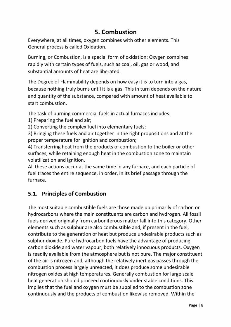
5. Combustion Everywhere, at all times, oxygen combines with other elements. This General process is called Oxidation.
Burning, or Combustion, is a special form of oxidation: Oxygen combines
rapidly with certain types of fuels, such as coal, oil, gas or wood, and
substantial amounts of heat are liberated.
The Degree of Flammability depends on how easy it is to turn into a gas,
because nothing truly burns until it is a gas. This in turn depends on the nature
and quantity of the substance, compared with amount of heat available to
start combustion.
The task of burning commercial fuels in actual furnaces includes: 1) Preparing the fuel and air; 2) Converting the complex fuel into elementary fuels; 3) Bringing these fuels and air together in the right propositions and at the proper temperature for ignition and combustion; 4) Transferring heat from the products of combustion to the boiler or other surfaces, while retaining enough heat in the combustion zone to maintain volatilization and ignition. All these actions occur at the same time in any furnace, and each particle of fuel traces the entire sequence, in order, in its brief passage through the furnace.
5.1. Principles of Combustion The most suitable combustible fuels are those made up primarily of carbon or hydrocarbons where the main constituents are carbon and hydrogen. All fossil fuels derived originally from carboniferous matter fall into this category. Other elements such as sulphur are also combustible and, if present in the fuel, contribute to the generation of heat but produce undesirable products such as sulphur dioxide. Pure hydrocarbon fuels have the advantage of producing carbon dioxide and water vapour, both relatively innocuous products. Oxygen is readily available from the atmosphere but is not pure. The major constituent of the air is nitrogen and, although the relatively inert gas passes through the combustion process largely unreacted, it does produce some undesirable nitrogen oxides at high temperatures. Generally combustion for large scale heat generation should proceed continuously under stable conditions. This implies that the fuel and oxygen must be supplied to the combustion zone continuously and the products of combustion likewise removed. Within the

Page | 9
combustion zone the air containing oxygen must be brought into intimate contact with the fuel, irrespective of whether it is in gaseous, liquid or solid form. This requires that fuel be well dispersed and the air turbulent in the combustion zone. Liquid and solid fuels require suitable division into small particles to ensure intimate mixing with the air. Solid fuels usually produce significant amounts of ash which must be removed from the combustion zone but only after sufficient time has been allowed for the combustible elements within the fuel particles to have fully reacted with the oxygen of the air. The purpose of combustion is to produce heat which is radiated from the combustion zone or carried away by the gaseous products of combustion. This heat is to be transferred effectively to the working fluid of the thermodynamic cycle but a certain portion is inevitably lost to the environment when the exhaust gases are discharged to the atmosphere. The main function of oil and coal burning system is to convert chemical energy into heat energy, which is utilized by the components of the boiler to convert water into the steam, which drives the turbine. The combustion element of fuel consists of carbon, hydrogen and small amount of sulphur. The exhaust gases released after combustion contains CO2, SO2 and CO, etc. When the coal is burnt with oxygen following reaction takes place and large amount of heat is released.
𝐶 + 𝑂2 → 𝐶𝑂2 𝑆 + 𝑂2 → 𝑆𝑂2 𝐶 + 𝑂2 → 2𝐶O
The average composition of air is 79% nitrogen and 21% oxygen by volume 77% nitrogen and 23% oxygen by weight
During combustion process nitrogen does not burn but passes through the chimney.
The amount of air required to burn any fuel can be calculated if the amount of the elements present in the fuel are known.
The amount of air to burn is known as theoretical air. If this quantity is not sufficient for complete combustion process then extra amount of air is supplied, known as excess air. In combustion process, turbulence, time, temperature and combustion efficiency are the important parameters to be considered.
The maximum combustion efficiency depends on
1. Design of boiler

Page | 10
2. Fuel used
3. Skill in obtaining combustion within the minimum amount of excess air.
5.2. Combustion Reactions C+ O2 = CO2 + 8084 kCals/kg of carbon 2C + O2 = 2CO + 2430kCals/kg of carbon
2H2 + O2 = 2H2O + 28,922 kCals/kg of hydrogen S + O2 = SO + 2,224 kCals/kg of sulphur
5.3. Significance of Various elements of coal
Fixed carbon: Solid fuel left after volatile matter is distilled off. It consists of mostly carbon. •Gives a rough estimate of heating value of coal
Volatile Matter:
It is an index of the gaseous fuels present.
Volatile Matter
•Proportionately increases flame length, and helps in easier ignition of coal.
•Sets minimum limit on the furnace height and volume.
•Influences secondary air requirement and distribution aspects.
•Influences secondary oil support Ash Content: Ash is an impurity that will not burn. •Reduces handling and burning capacity.
•Increases handling costs.
•Affects combustion efficiency and boiler efficiency
•Causes clinkering and slagging.
Moisture Content:
Moisture in coal must be transported, handled and stored. Since it replaces combustible matter, it decreases the heat content per kg of coal.
•Increases heat loss, due to evaporation and superheating of vapour
Page | 11
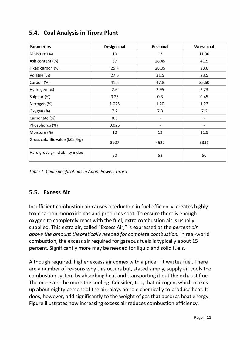
5.4. Coal Analysis in Tirora Plant
Parameters Design coal Best coal Worst coal
Moisture (%) 10 12 11.90
Ash content (%) 37 28.45 41.5
Fixed carbon (%) 25.4 28.05 23.6
Volatile (%) 27.6 31.5 23.5
Carbon (%) 41.6 47.8 35.60
Hydrogen (%) 2.6 2.95 2.23
Sulphur (%) 0.25 0.3 0.45
Nitrogen (%) 1.025 1.20 1.22
Oxygen (%) 7.2 7.3 7.6
Carbonate (%) 0.3 - -
Phosphorus (%) 0.025 - -
Moisture (%) 10 12 11.9
Gross calorific value (kCal/kg) 3927 4527 3331
Hard grove grind ability index 50 53 50
Table 1: Coal Specifications in Adani Power, Tirora
5.5. Excess Air Insufficient combustion air causes a reduction in fuel efficiency, creates highly toxic carbon monoxide gas and produces soot. To ensure there is enough oxygen to completely react with the fuel, extra combustion air is usually supplied. This extra air, called “Excess Air,” is expressed as the percent air above the amount theoretically needed for complete combustion. In real-world combustion, the excess air required for gaseous fuels is typically about 15 percent. Significantly more may be needed for liquid and solid fuels. Although required, higher excess air comes with a price—it wastes fuel. There are a number of reasons why this occurs but, stated simply, supply air cools the combustion system by absorbing heat and transporting it out the exhaust flue. The more air, the more the cooling. Consider, too, that nitrogen, which makes up about eighty percent of the air, plays no role chemically to produce heat. It does, however, add significantly to the weight of gas that absorbs heat energy. Figure illustrates how increasing excess air reduces combustion efficiency.

Page | 12
Fig 1. % Combustion Efficiency vs. % Excess Air (fuel oil)
Using too much excess air is one of the principal causes of poor fuel economy. For this reason, optimizing excess air usage can be one of the simplest ways to achieve significant fuel savings. NOTE: Excess Air and Fuel/Air Mixing Adding additional excess air is often done to reduce the CO concentration. Too much excess air can actually have the reverse effect of increasing CO. This results when fuel and air no longer mix properly in the burner, reducing the time of contact between oxygen and fuel and inhibiting a complete reaction. The impact of Excess air on Efficiency
In theory, to have the most efficient combustion in any combustion process, the quantity of fuel and air would be in a perfect ratio to provide perfect combustion with no unused fuel or air. This type of theoretical perfect combustion is called stoichiometric combustion. In practice, however, for safety and maintenance needs, additional air beyond the theoretical “perfect ratio” needs to be added to the combustion process—this is referred to as “excess air.” With boiler combustion, if some excess air is not added to the combustion process, unburned fuel, soot, smoke, and carbon monoxide exhaust will create additional emissions and surface fouling. From a safety standpoint, properly controlling excess air reduces flame instability and other boiler hazards. Even though excess air is needed from a practical standpoint, too much excess air can lower boiler efficiency. So a balance must be found between providing the optimal amount of excess air to achieve ideal combustion and prevent combustion problems associated with too little excess air, while not providing too much excess air to reduce boiler efficiency.
Page | 13
Research has shown that 15% excess air is the optimal amount of excess air to introduce into the boiler combustion process. While some boilers have been able to achieve 15% excess air at the top end of a boiler’s firing range, the challenge presents itself at the lower end of the firing range, or below 60% of the boiler’s maximum capacity. In general, most boilers tend to increase excess air requirements as the firing rate of the boiler decreases, leading to lower efficiency at the lower end of the firing range. To complicate matters, most boilers operate on the lower end of the firing range—so selecting a boiler that has low excess air throughout the firing range is important. This will ensure that you are always operating at high efficiencies.
5.6. 3T’s of Combustion When coal is burned in the body of a power plant, it is not just set alight like the coal in a domestic fireplace. It has to burn fast, for power is the energy converted per second, and it has to burn completely, for efficiency is a measure of how much energy is usefully harnessed rather than lost. The efficient combustion of coal needs the “three T’s”,
1. Temperature high enough to ignite the fuel, 2. Turbulence vigorous enough for the fuel constituents to be exposed to
the oxygen of the air, and 3. Time long enough to assure complete combustion.
The three requirements are best met by pulverized coal, which is forced into the furnace by an air stream under high pressure and is ignited as it enters through a nozzle. Time Incomplete combustion is a problem in fireplaces that largely contributes to fireplace emission levels. The longer the time combustion gases spend in the higher temperatures of the combustion zone the more completely they will combust and subsequently the lower the emissions will be from the fire. A refractory panel above the fire makes the flames travel a longer distance before exiting the combustion chamber. This longer path increase the residence time of the gases thus promoting a better overall burn and a reduction in emissions. Temperature The higher the temperature in the combustion zone the better the overall burn and the lower the emission.

Page | 14
Insulating refractory panels placed around the burning helps retain heat in the combustion zone. This again increases the burn temperature and promotes better combustion of coal. Turbulence The more turbulence that is encountered in the combustion gas path the better these gases mix with the surrounding oxygen, the more uniform the gas temperature, and more complete the burn.
5.7. Pulverization
For efficient combustion of coal in a coal fired power plant, pulverizing to a fine powder for burning is an important requirement. The basic requirement of coal combustion is that all the carbon particles in coal should get sufficient air to burn and release the heat. Because of large size of coal, some of the carbon particles do not come in contact with the air. These unburnt carbon particles go out with ash, which causes wastage of fuel and hence loss of efficiency. The pulverization process coverts coal into powdered form with particle size of about 75micron. This process increases the surface area of coal and hence fuel-air contact increases leading to better combustion of coal. Most coal fired power station boilers use pulverized coal. This technology is well developed, and there are thousands of units around the world, accounting for well over 90% of coal fired capacity. The coal is pulverized to a fine powder, so that less than 2% is +300 micro meter (μm) and 70-75 % is below 75 microns, for a bituminous coal. This system has many advantages such as ability to fire varying quality of coal, quick responses to changes in load, use of high pre-heat air temperatures etc. One of the most popular systems for firing pulverized coal is the tangential firing using four burners corner to corner to create a fireball at the centre of the furnace.
5.8. Reasons for improper combustion
Significant quantities of air in-leakage or “tramp” air into the furnace
Improper turbulence
Improper fuel sizing
Inadequate fuel flows
Inadequate fuel velocities
Improper temperatures

Page | 15
5.9. Combustion generated Pollutants Nitrogen Oxides (NOX) The release of oxides of nitrogen (nitrogen oxides and nitrogen dioxides) reacts with volatile organic compounds in the presence of sunlight to produce ground level ozone, the primary ingredient in smog. Nitrogen oxide also contributes to fine particulate matter, or soot. Both smog and soot are linked to a host of serious health effects. Nitrogen oxides also harms the environment, contributing to acidification of lakes and streams (acid rain). Sulphur Dioxide (SO2) Sulphur dioxide contributes to the formation of microscopic particles (particulate pollution or soot) that can be inhaled deep into the lungs and aggravate respiratory conditions such as asthma and chronic bronchitis, increasing cough and mucous secretion. Sulphur corrosion Sulphur corrosion is connected with the presence of alkali metals in coal: potassium K and sodium Na, which combined with sulphur form alkali sulphides Na2SO4 and K2SO4 condensing on the tubes’ surface. They aren’t directly responsible for corrosion because of their melting high-temperature (Na2 SO4 – 884 °C K2SO4 -1069 °C), however in the presence of SO3 they form corrosive pirosulfides and trisulfides near the surface of the evaporator tubes. Reactions of sulphur corrosion I. Pirosulfides Na2SO4 + SO3 ® Na2S2O7 (Tmelt = 389 °C) K2SO4 + SO3 ® K2S2O7 (Tmelt = 404 °C) II. Trisulfides: sodium- and potassium-iron: 3Na2SO4 + Fe2O3 + 3SO3 ® 2Na3Fe (SO4)3 (Ttopn= 624 °C) 3K2SO4 + Fe2O3 + 3SO3 ® 2K3Fe (SO4)3 (Ttopn= 618 °C) Mercury (Hg) Coal contains trace amounts of mercury that, when burned, enter the environment and human bodies, effecting intellectual development. Particulate Matter (PM) Also known as particle pollution, includes the tiny particles of fly ash and dust that are expelled from coal burning power plants. Fine particles are a mixture

Page | 16
of variety of different compounds and pollutants that originate primarily from combustion sources such as power plants, but also diesel trucks and buses, cars, etc. Fine particles are either emitted directly from these combustion sources or are formed in the atmosphere through complex oxidation reactions involving gases, such as sulphur dioxide or nitrogen dioxides. Among particles, fine particles are of particular concern because they are so tiny that they can be inhaled deeply, thus evading the human lungs. Smog It is the chemical reaction of sunlight, nitrogen oxides, and volatile organic compounds in the atmosphere, which leaves airborne particles and ground level ozone. Carbon Dioxide (CO2) It is the most significant greenhouse gas that contributes to global warming. The dangers of global warming include disruption of global weather patterns and ecosystems, flooding, severe storms, and droughts. A warming climate will also extend the range of infectious diseases. Corrosion hazard due to co-firing biomass and coal – chlorine corrosion Chlorine (Cl2) is particularly corrosive for steel at high temperature. It causes active oxidation of metal removing the protective layer of iron oxides, which are converted into porous, not protecting deposit. Sources of molecular chlorine (Cl2) near a tube surface are present in flue gas hydrogen chloride (HCl) and present in deposit alkali metals chlorides (KCl and NaCl).
Mechanism of chlorine corrosion Chlorine diffuses through deposit to metal and reacts with it Fe + Cl2 = FeCl2(s) Metal chlorides formed on the metal surface have high pressure at the temperature of 500 °C, therefore they diffuse through the protecting magnetite layer (Fe3O4) and damage it. After this iron chloride meets oxygen and undergoes oxidation: 2FeCl2 (g) + 3/2O2 ® Fe2O3(s) + 2Cl2 3FeCl2 (g) + 2O2 ® Fe3O4(s) + 3Cl2 As a result a new layer of iron oxides is formed, however porous and not protecting. Moreover released chlorine can return to metal.

Page | 17
Anti-corrosion protecting measures in pulverized coal-fired boilers 1. Maintenance of oxidizing atmosphere in the boundary layer at the furnace
walls. 2. Reduction of temperature of steam approximately to 537 °C. 3. Application of protecting coatings. 4. Additives to flue gas neutralizing some corrosive agents. 5. Reduction of sulphur, chlorine and alkali metals in fuels.
5.10. Need for combustion optimisation
Operating a boiler that is not optimised, or tuned, can
fallout of pulverised fuel, blocked pipes, or high mill pressure
erosion of mill, pipes and burner components
poor burner ignition, and flame instability and dislocation
incorrect primary and secondary air-to-fuel ratios
increased nitrous oxide production
increased levels of unburnt carbon
increased excess-air requirements
increased erosion between furnace and boiler exit
reduced boiler efficiency
localised furnace problems that can include inappropriate superheaters and reheater temperature profiles,
Increased slagging and greater water-wall wastage.
6. Combustion Analysis Combustion analysis is part of a process intended to improve fuel economy, reduce undesirable exhaust emissions and improve the safety of fuel burning equipment. Combustion analysis begins with the measurement of flue gas concentrations and gas temperature, and may include the measurement of draft pressure and soot level. To measure gas concentration, a probe is inserted into the exhaust flue and a gas sample drawn out. Exhaust gas temperature is measured using a thermocouple positioned to measure the highest exhaust gas temperature. Soot is measured from a gas sample drawn off the exhaust flue. Draft is the differential pressure between the inside and outside of the exhaust flue. Once these measurements are made, the data is interpreted using calculated combustion parameters such as combustion efficiency and excess air. A more in

Page | 18
depth analysis will examine the concentration of the undesirable products described earlier.
6.1. Why Perform Combustion Analysis?
Improve Fuel Efficiency The largest sources of boiler heat losses are shown Figure. Heat energy leaving the system exhaust flue (or stack) is often the largest single source of lost fuel energy and is made up of the Dry Gas loss and Latent Heat Loss. Although some flue loss is unavoidable, an equipment tune-up using combustion analysis data can often significantly reduce this source of heat loss and save fuel costs by improving fuel efficiency. Table 1 gives examples of yearly cost savings that can be realized by improving equipment efficiency by five percent.
Fig 2. Boiler Heat Losses
Boiler HP
Fuel Cost
$0.75 $1.00 $1.50 $2.00
100 $3,635 $4,847 $7,271 $9,694
200 $7,271 $9,694 $14,541 $19,389
300 $10,906 $14,541 $21,812 $29,083
500 $18,177 $24,236 $36,354 $48,471
800 $29,083 $38,777 $58,166 $77,554
Table 2. Possible savings per year with a 5% improvement in boiler efficiency (based on 3000 hours per year of operation).
Reduce Emissions

Page | 19
Carbon monoxide, sulphur dioxide, nitrogen oxides and particles are undesirable emissions associated with burning fossil fuels. These compounds are toxic, contribute to acid rain and smog and can ultimately cause respiratory problems. Federal and state laws govern the permissible emission rates for these pollutants under the guidance of the Clean Air Act and oversight of the federal Environmental Protection Agency (EPA). State and local environmental agencies also exert authority in regulating the emissions of these pollutants. Combustion analysis is performed to monitor toxic and acid rain forming emissions in order to meet these federal, state and local regulations. For specific information on emissions as they relate to a particular region, contact the local regulatory agency. Improve Safety Good equipment maintenance practice, which includes combustion analysis, enables the boiler technician to fully verify and maintain the equipment operating specifications for safe and efficient operation. Many boiler manufacturers suggest that flue gas analysis be performed at least monthly. Boiler adjustments that affect combustion will tend to drift with time. Wind conditions and seasonal changes in temperature and barometric pressure can cause the excess air in a system to fluctuate several percent. A reduction in excess air can cause, in turn, a rapid increase of highly toxic carbon monoxide and explosive gases, resulting in rapid deterioration in system safety and efficiency. Low draft pressures in the flue can further result in these combustion gases building up in the combustion chamber or being vented indoors. Excessive draft pressures in the flue also can cause turbulence in the system. This can prevent complete combustion and pull explosive gases into the flue or cause flame impingement and damage in the combustion chamber and to the heat exchanger material.
6.2. What’s measured?
Combustion analysis involves the measurement of gas concentrations, temperatures and pressure for boiler tune-ups, emissions checks and safety improvements. Parameters that are commonly examined include: • Oxygen (O2) • Carbon Monoxide (CO) • Carbon Dioxide (CO2) • Exhaust gas temperature • Supplied combustion air temperature • Draft • Nitric Oxide (NO)
Page | 20
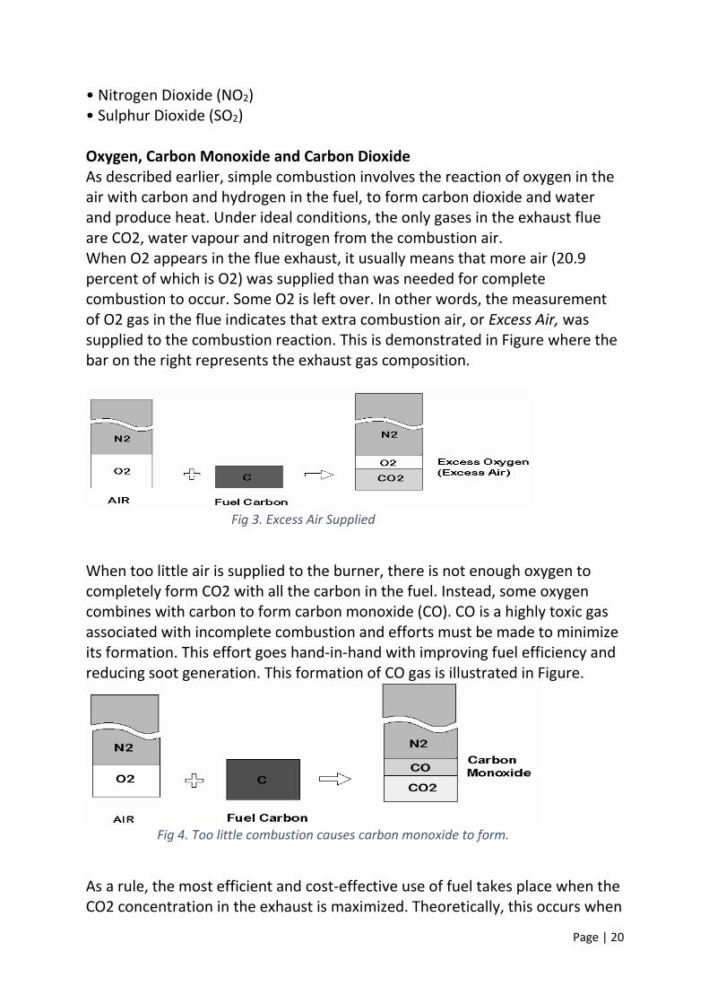
• Nitrogen Dioxide (NO2) • Sulphur Dioxide (SO2) Oxygen, Carbon Monoxide and Carbon Dioxide As described earlier, simple combustion involves the reaction of oxygen in the air with carbon and hydrogen in the fuel, to form carbon dioxide and water and produce heat. Under ideal conditions, the only gases in the exhaust flue are CO2, water vapour and nitrogen from the combustion air. When O2 appears in the flue exhaust, it usually means that more air (20.9 percent of which is O2) was supplied than was needed for complete combustion to occur. Some O2 is left over. In other words, the measurement of O2 gas in the flue indicates that extra combustion air, or Excess Air, was supplied to the combustion reaction. This is demonstrated in Figure where the bar on the right represents the exhaust gas composition.
Fig 3. Excess Air Supplied
When too little air is supplied to the burner, there is not enough oxygen to completely form CO2 with all the carbon in the fuel. Instead, some oxygen combines with carbon to form carbon monoxide (CO). CO is a highly toxic gas associated with incomplete combustion and efforts must be made to minimize its formation. This effort goes hand-in-hand with improving fuel efficiency and reducing soot generation. This formation of CO gas is illustrated in Figure.
Fig 4. Too little combustion causes carbon monoxide to form.
As a rule, the most efficient and cost-effective use of fuel takes place when the CO2 concentration in the exhaust is maximized. Theoretically, this occurs when

Page | 21
there is just enough O2 in the supplied air to react with all the carbon in the fuel supplied. This quantity of supplied air is often referred to as the theoretical air. The theoretical air required for the combustion reaction depends on fuel composition and the rate at which the fuel is used (e.g. pounds per hour, cubic feet per minute, etc.). In real-world combustion, factors such as the condition of the burner and the burner design also influence the amount of air that is needed. The theoretical air is rarely enough. The general relationship between the O2 supplied and the concentration of CO2 and CO in the exhaust is illustrated in Figure. As the air level is increased and approaches 100% of the theoretical air, the concentration of CO molecules decreases rapidly as they pick up additional oxygen atoms and form CO2. Still more combustion air and CO2 reaches a maximum value. After that, air begins to dilute the exhaust gases, causing the CO2 concentration to drop. The maximum value of CO2 is dependent on the type of fuel used.
Fig 5. Combustion Gas Concentrations at Percent
Temperature and Draft
Exhaust Gas Temperature and Supplied Combustion Air Temperature Heat leaving the exhaust flue with the hot gases is not transferred to do useful work, such as producing steam. This heat loss becomes a major cause of lower fuel efficiency. Because the heat content of the exhaust gas is proportional to

Page | 22
its temperature, the fuel efficiency drops as the temperature increases. An example of efficiency loss due to the increase in stack gas temperature is shown in Figure. When determining heat loss from the flue, the temperature of the supply air is subtracted from the flue gas temperature. This gives the net temperature and accounts for the heat supplied to the system by the supply air. Some heat loss is unavoidable. The temperature in the flue needs to remain high enough to avoid condensation inside the stack. One process for recovering some of the heat loss in the exhaust is to use the hot flue gases to preheat the supply air before it is introduced into the combustion chamber.
Fig 6. Flue Temperature vs. % Efficiency (fuel oil)
Draft Draft refers to the flow of gases through the heat generating equipment, beginning with the introduction of air at the back of the burner. Once combustion occurs, the heated gas leaves the combustion chamber, passes heat exchangers and exits the exhaust stack. Depending upon the design of the equipment, draft is natural, meaning combustion air is pulled in by buoyant heated gases venting up the stack, or it is mechanical, meaning air is pushed or pulled through the system by a fan. Often, draft relies on a combination of both natural and mechanical means. Adequate draft is typically verified by measuring the pressure in the exhaust stack. The manufacturer of the fuel burning equipment provides specifications for the required draft pressure and locations for making the draft measurement. Measurement is important since environmental influences such as changes in barometric pressure and ambient temperature can influence the flow. Typical draft pressures are in the range of –0.5 to 0.5 inches of water column.

Page | 23
Excessive draft can prevent heat transfer to the system and increase the flue temperature if the excess air percentage is not elevated. If the excess air increases from the high draft, the flue temperature will decrease. Low draft pressures can cause temperatures in the flue to decrease, allowing water vapour to condense in the flue, forming acid and damaging the system. Nitrogen Oxides (NOx) Nitrogen oxides, principally nitric oxide (NO) and nitrogen dioxide (NO2), are pollutant gases that contribute to the formation of acid rain, ozone and smog. Nitrogen oxides result when oxygen combines with nitrogen in the air or in the fuel. NO is generated first at high flame temperatures, then oxidizes further to form NO2 at cooler temperatures in the stack or after being exhausted. The NO concentration is often measured alone, and the NO2 concentration is generally assumed to comprise an additional five percent of the total nitrogen oxides. The nitrogen oxide gas concentrations are sometimes combined and referred to as the NOX concentration. Sulphur Dioxide (SO2) Sulphur dioxide combines with water vapour in the exhaust to form a sulphuric acid mist. Airborne sulphuric acid is a pollutant in fog, smog, acid rain and snow, ending up in the soil and ground water. Sulphur dioxide itself is corrosive and harmful to the environment. Sulphur dioxide occurs when the fuel contains sulphur and where the emission levels are directly related to the amount of sulphur in the fuel. The most cost-effective way to reduce sulphur emissions is to select a Low-sulphur or de-sulphured fuel. Hydrocarbons (HCs)/Volatile Organic Compounds (VOCs) Organic compounds are sometimes present in the combustion exhaust products because of incomplete combustion. Hydrocarbons (HCs), or volatile organic compounds (VOCs), are best reduced through proper burner maintenance and by maintaining the proper air/fuel mixture. Soot Soot is the black smoke commonly seen in the exhaust of diesel trucks, and is present whenever fuel oils or solid fuels are burned. Excessive soot is undesirable because it indicates poor combustion and is responsible for coating internal heat transfer surfaces, preventing good thermal conductivity. Over time, serious damage to the heat exchanger can occur.

Page | 24
Soot is primarily unburned carbon, and is formed for the same reasons CO is formed—insufficient combustion air, poor mixing and low flame temperature. As with CO, it is usually impossible or impractical to entirely eliminate soot formation for some fuel types.
6.3. Measurement Tools Manual Gas Measurements The Orsat analyser is a gas concentration analysis tool typically used to manually sample CO2, O2 and CO from the flue of a combustion system. The Orsat analyser determines the gas concentrations from a sample of gas extracted from the flue and bubbled through solutions of reagents that selectively absorb each gas. By measuring the decrease in gas volume over the liquid reagents, the amount of gas absorbed is indicated. From this information, stack gas concentration is calculated. Manual gas measurements are time consuming and do not accurately reflect real-time adjustments made to a system. Portable Electronic Instruments In recent years, electronic instruments such as the CA-CALC™ Combustion Analyser from TSI Incorporated have been developed to analyse combustion routinely for tune-ups, maintenance and emissions monitoring. These instruments are extractive. They remove a sample from the stack or flue with a vacuum pump and then analyse the sample using electrochemical gas sensors. Thermocouples are used for stack and combustion air temperature measurements, and a pressure transducer is used for the draft measurement. An on-board computer performs the common combustion calculations, eliminating the need to use tables or perform tedious calculations. Electronic instruments show the results of boiler adjustments in real-time and give more accurate information to help ensure that a system has been tuned properly. Continuous Emission Monitors Continuous emission monitors, or CEMS, are a class of electronic instruments designed to measure exhaust stack gases and temperature continuously. CEMs are sometimes used for combustion control, but typically are used for monitoring pollutant gas emissions as required by government regulations. CEMs can use both extractive and in-situ (sensors in the stack) sampling methods, and employ a variety of electronic sensor technologies for gas
Page | 25
detection. CEMs are used most often on larger installations or when required by regulatory agencies.
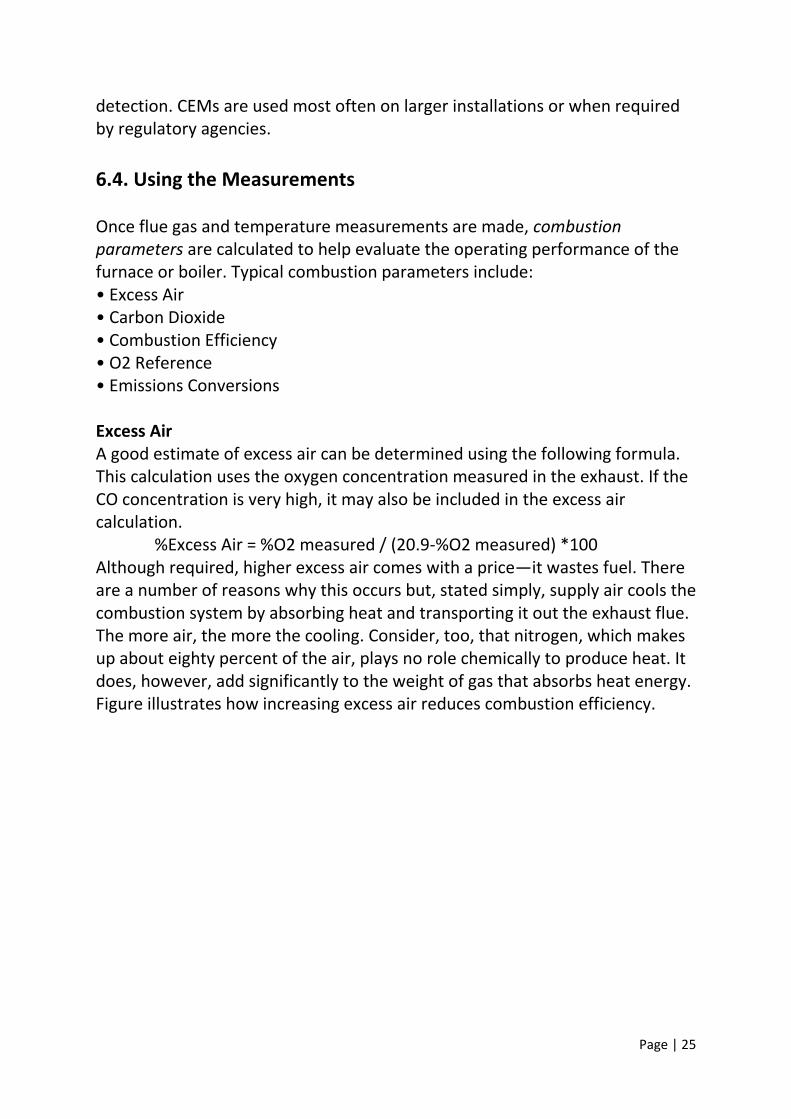
6.4. Using the Measurements Once flue gas and temperature measurements are made, combustion parameters are calculated to help evaluate the operating performance of the furnace or boiler. Typical combustion parameters include: • Excess Air • Carbon Dioxide • Combustion Efficiency • O2 Reference • Emissions Conversions Excess Air A good estimate of excess air can be determined using the following formula. This calculation uses the oxygen concentration measured in the exhaust. If the CO concentration is very high, it may also be included in the excess air calculation. %Excess Air = %O2 measured / (20.9-%O2 measured) *100 Although required, higher excess air comes with a price—it wastes fuel. There are a number of reasons why this occurs but, stated simply, supply air cools the combustion system by absorbing heat and transporting it out the exhaust flue. The more air, the more the cooling. Consider, too, that nitrogen, which makes up about eighty percent of the air, plays no role chemically to produce heat. It does, however, add significantly to the weight of gas that absorbs heat energy. Figure illustrates how increasing excess air reduces combustion efficiency.

Page | 26
Fig 7. Combustion Efficiency vs Excess Air
Using too much excess air is one of the principal causes of poor fuel economy. For this reason, optimizing excess air usage can be one of the simplest ways to achieve significant fuel savings. Calculating the Carbon Dioxide Concentration Carbon dioxide (CO2) forms when carbon in the fuel combines with O2 in the combustion air. When there is just enough O2 supplied to react with the carbon in the fuel, the CO2 concentration in the stack exhaust is at its highest level. This is generally at or close to the ideal operating condition for the heat generating equipment. The maximum possible CO2 exhaust concentration depends ultimately on the carbon content of the fuel being burned. This number, the CO2 maximum, appears often in combustion calculations, such as the one below for determining the percent of CO2 in the exhaust. %CO2 (by volume) = CO2 (maximum) * [(20.9-%O2 measured)/20.9] NOTE: Using Measured O2 to Determine CO2 Using the O2 concentration to determine the concentration of CO2 has advantages compared to measuring CO2 directly. As indicated in Figure 5, the same CO2 concentration is possible when there is too little air supplied (less than 100% theoretical air) or too much air (greater than 100% theoretical air). When CO2 is measured alone, it is not possible to tell if the mix of exhaust gases is represented by those to the left of the CO2 peak or those to the right of the CO2 peak. When to the left of the peak, high levels of toxic CO are

Page | 27
present, resulting in a potentially dangerous operating condition. By detecting sufficient O2 in the exhaust, the combustion reaction stays on the right side of the CO2 peak, minimizing the formation of CO. Determining Combustion Efficiency Combustion efficiency is a measure of how effectively energy from the fuel is converted into useful energy (e.g. to create steam). Combustion efficiency is determined by subtracting the heat content of the exhaust gases, expressed as a percentage of the fuel’s heating value, from the total fuel-heat potential, or 100%, as shown in the formula below. %Combustion Efficiency = 100% - (Stack heat losses/Fuel heating value * 100) Stack heat losses are calculated using gas concentration and temperature measurements from combustion analysis, and using the fuel’s specifications for chemical composition and heat content. These fuel specifications are unique properties of the fuel, determined from chemical analysis by the fuel supplier. Stack heat losses are primarily from the heated dry exhaust gases (CO2, N2, O2) and from water vapour formed from the reaction of hydrogen in the fuel with O2 in the air. When water goes through a phase change from liquid to vapour, it absorbs a tremendous amount of heat energy in the process. This “heat of vaporization,” or latent heat, is usually not recovered. The white cloud seen exiting a stack on a cold day is mostly condensing water vapour giving up its latent heat to the atmosphere. NOTE: Other Definitions of Efficiency It is important to recognize that other definitions of efficiency are often used to describe furnace or boiler performance in addition to combustion efficiency. Thermal efficiency or boiler efficiency are examples. These may include or exclude sources of heat loss as part of their calculation. Combustion efficiency, for example, does not include losses from radiation or steam leaks. Sometimes the latent heat of water formation is not included. There are also fundamental differences between calculations performed in the U.S. and those performed in some European countries. When comparing the performance of equipment from different manufacturers, it is important to know how an efficiency number is calculated. NOTE: Why use Combustion Efficiency?

Page | 28
Combustion efficiency, determined from combustion analysis, is a cost-effective way to improve equipment operation and reduce fuel expense. The stack losses used in combustion efficiency calculations are simple to determine using combustion analysis. Other losses, such as those from steam leaks, radiation or boiler blow-down, are much more difficult to assess. Stack losses are typically the largest source of energy waste. If the equipment is properly maintained, losses such as those from steam leaks are minimal. Convection and radiation losses are often small also, and usually unavoidable. The O2 Reference As discussed earlier, excess air is supplied to the combustion process to ensure that there is enough oxygen to completely react with the fuel. Excess air is measured in the flue as a percentage of O2. This excess air dilutes the concentration of other gases measured. Local regulatory agencies have guidelines for monitoring NO, NO2, CO, and SO2 gases. Generally, it is required that the concentration of these gases be corrected for the diluting effects of excess air. The amount of excess air is determined from the O2 concentration measured in the flue. The measured O2 concentration, together with the O2 reference value is used in the equation below to obtain the corrected gas concentration. O2 reference values of 3 and 6 percent are often used, giving a corrected gas concentration equivalent to that at oxygen concentrations of 3 or 6 percent. When an O2 reference of zero is used, the gas concentration is referred to as undiluted or air free. To obtain the O2 referenced concentration of gasses in the flue, the following equation is used: Corrected PPM = measured PPM * [(20.9 – O2 reference) / (20.9 – O2 measured)] Emission Conversions A measure of the toxic gas concentration in parts per million (PPM) or percent does not indicate the actual weight of pollutant entering the atmosphere. The EPA requires the conversion of pollutant concentrations to pounds per million Btu of fuel consumed (lb/MBtu). This is done so the weight of pollutants can be readily determined from the pollutant concentration and the rate of fuel usage. EPA Method 19 has equations for performing the conversions and presents fuel-specific conversion factors for use in performing the calculations.

Page | 29
7. Fuel Firing System
7.1. Introduction
The fuel firing system of the boiler provide controlled, efficient conversion of the chemical energy of the fuel into heat energy which in turn is transferred to heat absorbing surfaces. Any fuel burning system must introduce the fuel and air for combustion, mix these reactants, ignite the combustible mixture and distribute the flame envelope and products of combustion.
7.2. Characteristics of Ideal Firing System
An ideal fuel firing system fulfilling the above functions will have the following
characteristics
- No excess oxygen or unburned combustibles in the end products of combustion
- A low rate of auxiliary ignition energy input to initiate combustion.
- An economic reaction rate between fuel and oxygen compatible with acceptable N0x & SOx formation.
- An effective method of handling and disposing of the solid impurities introduced with the fuel.
- Uniform distribution of product weight and temperature in relation to the parallel circuits of heat absorbing surface.
- A wide and stable firing range.
- Fast responses to changes in firing rate.
- High equipment availability with low maintenance.
In actual practice, compromises must be made to achieve balance between combustion efficiency and cost. For example with stoichiometric air infinite residence time will be required at temperature above ignition temperature for complete combustion and so excess air is used resulting in unconsumed oxygen in the product gas.

Page | 30
7.3. Firing System Concepts
Successful molecular contact of reactants of combustion through turbulence
can be achieved by producing two methods of flow pattern in the furnace.
In the first concept, the fuel and air are divided and distributed into many similar streams. Each stream is treated independently to provide multiple flame envelopes called multi flame envelope concept.
In the second concept a single flame envelope is produced, by providing interaction between all streams of air and fuel introduced into the furnace. This is called single flame envelope concept.
7.4. Comparison of Single and Multiflame Concept
The single flame envelope provides interaction between all streams of fuel and air introduced into the furnace and so precise subdivision of fuel and air at each point of admission is not required. Allows more time for contact between all fuel and air molecules and mechanical turbulence is sustained throughout the furnace.
The multi flame envelope requires accurate subdivision fuel and air supplied to the furnace. This concept limits the opportunity for sustained mechanical turbulence particularly in the early stages of combustion.
7.5. Firing Systems: This can be broadly classified into direct firing system and indirect firing or intermediate bunker system. Both the systems can use any type of mill. Either hot gas or air can be used for drying and transporting the coal.
Direct Firing System
In this type of firing system, coal is fed to the mill at controlled quantity. Hot air whose temperature can be controlled with the help of cold air is permitted to flow through the mill. The air dries the coal and picks up the milled product and flows through the classifier where higher size particle is rejected back to the mill.
The fine coal is carried by the air through the coal burner to the combustion chamber. The flow through the system is carried out by primary air fan or by exhauster. In case of hammer mills forced draft itself can do the purpose of primary air fan.

Page | 31
This system is simple involving minimum equipment hence minimum initial cost and maintenance cost. As there is no fine coal storage the mill load is varied according to the boiler load. Hence part load operation of mill is essential and this means increase in power consumption and maintenance per tonne of coal.
Mill outage will result in reduction of boiler output if spare mills are not provided or available. This is best suited to use with high speed and medium speed mills as the mill power consumption varies in direct proportion to the mill load. Tube ball mills with this system is also used but to a limited extent.
Indirect Firing System
In this system, mills are operated independent of boiler loading and pulverised coal is stored in the intermediate bunker.
From the bunker it is taken to combustion chamber with the help of primary air fan. Boiler loading is controlled by the amount of pulverised fuel fed to boiler. Hot air or gas is used for drying and transporting.
Cyclone type separators are used to separate the fine coal from coal, air/gas mixture for storing in fine coal bunker. As fine coal dust cannot be completely removed by cyclone type separators, a certain portion of very fine particle is carried along by air/vapour. This necessitates admissions of vapour/air into the combustion chamber to utilise the heating value of fine coal dust carried along with vapour/air. This can be done by providing separate vapour burners or the air can be used as primary air for carrying the fine coal.
This system using gas as drying medium requires one additional fan called vapour fan for each mill. If air is used for drying, one fan called mill fan can be designed to carry out both the functions of primary air fan and vapour fan.
This system favours the following advantages:
a) Mill can be operated always at full load, thus saving in power, maintenance cost per tonne of coal for the selected mill. Hence this system is adopted normally for tube ball mill.
b) Separate spare mill is not necessary for carrying out the maintenance. Certain percentage as spare capacity on total basis is normally enough.
c) Mills can be operated during off peak hours only and hence higher power out during the peak period.

Page | 32
7.6. Methods of Fuel Firing There are many ways of firing the coal in furnace. They are: a) Vertical firing b) Horizontal firing c) Impact firing d) Corner or tangential firing Vertical Firing Vertically fired systems are used only to fire solid fuels that are difficult to ignite
such as coals with moisture, ash, and free volatile matter less than 13 percent. They
require less supplementary fuel than the horizontal or tangentially fired system but
have more complex firing equipment and therefore more complex operating
characteristics.
The firing concept and the arrangement of the burners in this system are shown in Fig. Pulverised coal is discharged through the nozzles in the furnace arch. A portion of the heated combustion air is introduced around the fuel nozzles and though adjacent auxiliary parts. High-pressure air jets are used to avoid short-circuiting of fuel-air streams to the furnace discharge. Tertiary air ports are located in a row along the front and rear walls of the lower furnace.
This firing system produces a long looping flame in the lower furnace, with the hot gases discharging up the center. A portion of the total combustion air is withheld from the fuel stream until it projects well down into the furnace. This arrangement has the advantage of heating the fuel stream separately from a significant portion of its
Fig 8. Vertical Firing System

Page | 33
combustion air to provide good ignition stability. The delayed introduction of tertiary air provides needed turbulence at a point in the flame where partial dilution from the products of combustion has occurred. The furnace flow pattern passes the hot product gases immediately in front of the fuel nozzles to provide a ready source of inherent ignition energy, which raises the primary fuel stream to ignition temperature. The flow pattern also ensures that the largest entrained solid fuel particles with the lowest surface area to weight ratio, have the largest residence time in the combustion chamber.
Horizontal Firing (Front Firing)
In horizontally fired systems the fuel is mixed with combustion air in individual burner registers. The burners are located in rows through a wind box receiving hot secondary air either on the front wall only or on both front and rear walls. A typical burner is shown in Fig.
The coal and primary air are introduced tangentially to the coal nozzle, thus
imparting strong rotation within the nozzle. Secondary air from the windbox is
admitted to the burner through adjustable radial or axial in flow swirl vanes called air
registers. These vanes impart rotation to the secondary air. The degree of air swirl,
coupled with the flow-shaping contour of the burner throat, establishes a re-
circulation pattern extending several throat diameters into the furnace. Once the
coal is ignited hot products of combustion are directed back towards the nozzle to
provide the ignition energy necessary for stable combustion.
This type of coal burners is fitted with an oil burner mounted in a central
support tube for coal burner ignition.

Page | 34
Because the major portion of the combustion process must take place within
the re-circulation zone, it is imperative that the air fuel ratio to each burner is within
close tolerances. The rate of combustion drops of rapidly as the reactants leave the
re-circulation zone and interaction between flames occurs only after that point. The
degree of interaction depends on burner and furnace configurations.
Fig 9. Wall firing Burner
Fig 10. Burner for Wall Firing

Page | 35
Impact Firing
This is the arrangement with the type of burner used with slag tap furnaces where the ash is kept in a molten state on the furnace floor and tapped off as and when necessary. Corner or Tangential Firing
The tangentially fired system is based on the concept of a single flame envelope. Both fuel and combustion air are projected from the corners of the furnace along a line tangent to a small circle lying in a horizontal plane at the centre of the furnace. Intensive mixing occurs where these streams meet. A rotated motion similar to that of a cyclone is imparted to the flame body, which spreads out and fills the furnace area.
In this system at each corner of the furnace a wind box assembly is installed. Fig. shows a typical wind box. The wind box is vertically divided into number of compartments. Each compartment receives hot secondary air from the secondary air duct through a damper called secondary air damper.
Alternate compartments of the wind box are provided with coal nozzles
through which the pulverised coal from the mill is delivered to the furnace. Four
corner nozzles of one elevation are generally connected to one mill. In these
compartments secondary air is admitted to the furnace surrounding the coal nozzles.
These compartments are called fuel compartments and the secondary air dampers of
these compartments are termed fuel air dampers.
The other compartments are known as Auxiliary air compartments. Each
auxiliary air compartment between two fuel compartments is provided with oil gun
for firing the oil. The secondary air dampers of the auxiliary air compartments are
called auxiliary air dampers.
With this arrangement the fuel and air are admitted to the furnace from
corners in vertical layers. The secondary air dampers control the air to each
compartment, making it possible to vary the distribution of air over the height of the
wind box, the velocities of the air stream, change the mixing rate of fuel and air and
control the distance from the nozzle at which the coal ignites.
It is customary that the auxiliary air dampers are set to modulate to maintain
a fixed wind box to furnace differential pressure to have sufficient air stream velocity
to achieve sustained turbulence in the furnace. The fuel air dampers are set to

Page | 36
modulate according to the speed of the raw coal feeder corresponding to that
elevation. This ensures the distribution of secondary air in the furnace in accordance
to the elevation loading.
In this arrangement, there will be a facility for tilting the fuel and air nozzles of
the wind box compartments. All these nozzles (Elevations and corners) tilt in unison
to raise and lower the flame in the furnace to control furnace heat absorption and
thus heat absorption in the super heater and reheater sections.
The most effective method for producing intense turbulence is by the impingement of one flame on another. This action is secured through the use of burners located in each of the four corners of the furnace, close to the floor or the water-screen. The burner nozzles are so directed that the streams of coal and air are projected along a line tangent to a small circle, lying in a horizontal plane, at the centre of the furnace. Intensive mixing occurs where these streams meet. A scrubbing action is present which assures contact between the combustible and oxygen, thus promoting rapid combustion and reducing carbon loss. The ignition at each burner is aided by the flame from the preceding one.
With tangential firing the furnace is essentially the burner, consequently air and coal quantities need not be accurately proportional to the individual fuel nozzle assemblies. Turbulence produced in the furnace cavity is sufficient to combine all the fuel and air. This continuously insures uniform and complete combustion so that test performance can be maintained throughout daily operation. With other types of firing the fuel and air must be accurately proportioned to individual burners making it difficult to always equal test results.
With this type of firing, combustion is extremely rapid and short flame length results. The mixing is so intense that combustion rates exceeding 35,000 Btu/ (ft3·h) or 360 kW/m3 are practical under certain conditions. However, since there is considerable impingement of flame over the furnace walls it is absolutely necessary that they be fully water-cooled. This sweeping of the water-cooled surfaces, in the furnace, by the gas increases the evaporation rate. Thus, in addition to absorption by radiation from the flame envelope, there is transfer by convection, and the resulting furnace temperatures are lower than with other types of burners, even though the heat liberation rates may be somewhat higher. Tangentially-fired furnaces are usually clean in the upper zone and, as a result, both the furnace and the boiler are comparatively free from objectionable slag deposits.
Page | 37
7.7. Components of Fuel Firing System
The essential components for a pulverised coal fired boiler-firing system are
- Ignition system
- Oil guns and atomisers
- Flame scanner
Ignition System
Any boiler firing system needs a suitable ignition system to provide ignition
energy to the flammable mixture of fuel and air introduced to the furnace.
Combustion reaction starts only when the flammable mixture is heated to its ignition
temperature.
To initiate combustion of any fuel and to keep the flame stable, continuous
supply of ignition energy is required which is supplied in the form of heat. This
ignition energy can be called as the total ignition energy. This total ignition energy
can be derived from the fuel itself when it is burning in stable condition called as
inherent ignition energy, supplied by external sources as auxiliary ignition energy or
combination of both. Hence
Total ignition Energy = Inherent Ignition Energy + Auxiliary Ignition Energy
When a fuel is to be lighted up, the inherent ignition energy available from it is
at zero level so the entire amount of ignition energy required has to be obtained from
auxiliary ignition energy sources only. Also, immediately after light up of the fuel the
heat available from combustion may not be equivalent to the Total ignition energy.
Hence under low firing rates still the auxiliary ignition energy will be required.
When the firing becomes stable and heat available from the combustion of main fuel
is greater than total ignition energy no more auxiliary ignition energy will be required.
This condition will be stated as self-sustainable.
The ignition energy required at any given instant depend on many factors such as
- Location
- Fuel quality

Page | 38
- Fuel parameters
- Combustion air parameter
- Fuel air distribution
- Total fuel air ratio
- Mass burner flow rate
In a coal-fired boiler, the auxiliary ignition energy for coal firing is provided by suitably located oil burners. For igniting the oil while starting the oil burners, ignitors are used in the firing system.
Requirements of an Auxiliary Ignition System
An auxiliary ignition system provided for igniting the oil burner of a boiler should
meet the following criteria.
It should be one capable of measuring the ignition energy required and
supplied. Ignition energy should be located very close relative to main fuel admission
so as to readily ignite main fuel as it enters the furnace.
Ignition energy equipment should contain a fuel quantity control arrangement,
with a self-resetting or zero run back of the scanning or proving loop. The
quantitative and qualitative feedback of the scanning or proving loop should totalize
both flame presence and actual heat input.
Interlocking with main fuel admission should be used.
An ignition system, which meets these design criteria also, has the inherent capability of being used as a flame proven for its associated main fuel burner. When the ignition system is proven in service, fuel supply through the main oil burners can safely be made.
Ignitor Types
The ignitors that are available now can use any of the load carrying fuels
available to the boiler. Such fuels include natural gas, all grades of fuel oil etc.
however the application of the various ignitor types is largely a function of user
preference, ignitor fuel availability and ignitor fuel economics.
Page | 39
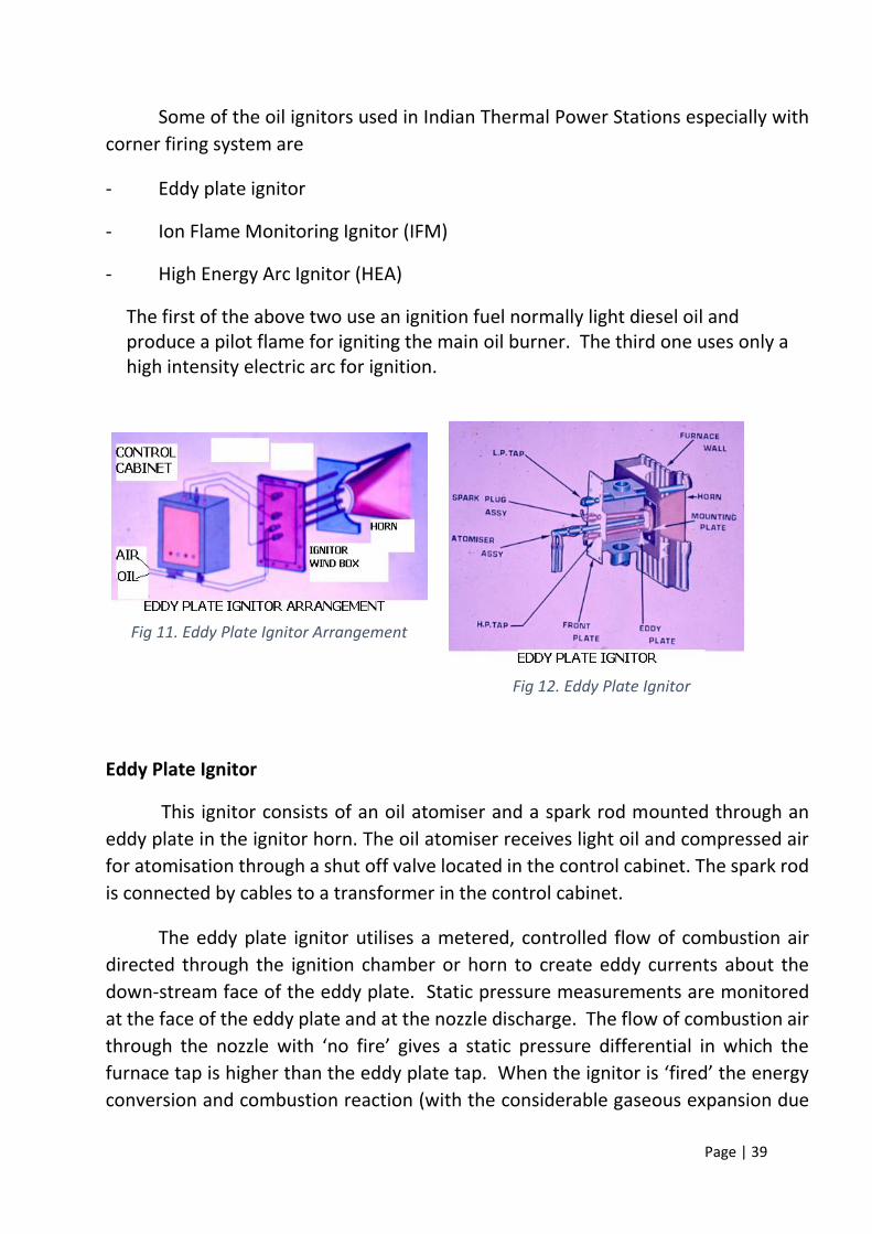
Some of the oil ignitors used in Indian Thermal Power Stations especially with
corner firing system are
- Eddy plate ignitor
- Ion Flame Monitoring Ignitor (IFM)
- High Energy Arc Ignitor (HEA)
The first of the above two use an ignition fuel normally light diesel oil and produce a pilot flame for igniting the main oil burner. The third one uses only a high intensity electric arc for ignition.
Eddy Plate Ignitor
This ignitor consists of an oil atomiser and a spark rod mounted through an
eddy plate in the ignitor horn. The oil atomiser receives light oil and compressed air
for atomisation through a shut off valve located in the control cabinet. The spark rod
is connected by cables to a transformer in the control cabinet.
The eddy plate ignitor utilises a metered, controlled flow of combustion air
directed through the ignition chamber or horn to create eddy currents about the
down-stream face of the eddy plate. Static pressure measurements are monitored
at the face of the eddy plate and at the nozzle discharge. The flow of combustion air
through the nozzle with ‘no fire’ gives a static pressure differential in which the
furnace tap is higher than the eddy plate tap. When the ignitor is ‘fired’ the energy
conversion and combustion reaction (with the considerable gaseous expansion due
Fig 11. Eddy Plate Ignitor Arrangement
Fig 12. Eddy Plate Ignitor

Page | 40
to both the temperature rise and energy release) creates a backpressure on the eddy
plate pressure tap. This results in a positive reversal of differential measurement
between the two taps. The differential is rather significant and can be easily
measured with relatively simple diaphragm meters. At low inputs, below 2 million
Btu per hour, the ignitor differential switch can be set up to be quantitative in
determination of the quantity of ignition energy and therefore, the ignitor is both
quantitative, indicating the flame, and quantitative, indicating the level of igniting
energy. When the device is used for quantities 2 million Btu and above an
independent flow measurement is made of the actual fuel flow through the ignition
system. This is accomplished through a unitized flow controller with a flow switch,
which maintains a constant differential across an orifice. This differential is
continuously monitored and is a permissive in the logic of the ignitor. To release the
external interlocks both flame indication and quantitative fuel flow must be proven.
The eddy plate ignitor has been proven to be an exceptionally stable and reliable device. The eddy plate gas ignitor has been used even as a main monitoring device without any optical scanners for the main fuel burner because of its thorough reliability.
IFM Ignitor
The Ionic flame monitoring side ignitor (IFM) can spark ignite high calorific value gases or distillate oil. This is having a similar arrangement like eddy plate ignitor with an exception for proving ignition. The IFM design follows the traditional philosophy of providing an ignitor with both qualitative and quantitative indications of flame. The system incorporates the principle of flame ionisation, which is present in all turbulent hydrocarbon flames, to deduct the presence of combustion. In the burning process energy is liberated by the combination of two or more reactants to form a product with lower energy level.

Page | 41
During this burning process many ions (charged particles) are liberated taking the form of electrons and charged nuclei. When a D.C. potential is placed across the flame a varying current is generated due to the variable resistance the flame presents to the rod.
The system operates by imposing a DC potential on the rod that is in contact with the flame. The DC voltage is modulated plus or minus around the imposed level by the flame and the imposed signal is then filtered out. The variance is then amplified, changed to a pulse shape and used to drive a flame indication relay.
The circuit is designed to be fail-safe. If there is a component failure, a short circuit in the flame rod or lead wire or a direct AC interference, a “no flame indication” will occur.
High Energy Electric Arc (HEA) Ignitors
The High Energy Electric Arc Ignitor is developed to offset the decreasing availability and rising cost of ignition fuels such a natural gas, HSD and LDO. The HEA ignitor effectively eliminates dependence on these fuels by igniting Heavy Oil and L.S.H.S. directly. The HEA ignitor is used with a discriminating scanner, which proves the operation of the main burner.
Fig 13. I.F.M. Ignitor

Page | 42
The HEA ignition system consists of
- A high energy arc ignitor
- An oil compartment capable of producing a stable flame at all loads.
- A flame detecting system sensitive only to its associated oil guns.
- A control system to co-ordinate all the components and provide for unit safety.
The HEA ignitor can ignite fuel oils ranging from distillate to Heavy oils and crude oils. The ignitor is a self-contained electrical discharge device for producing a high intensity spark. Use of high resistance transformer to produce a full wave charging circuit and to control spark rate enables the sealed power supply unit to store maximum energy and to deliver a greater percentage of this energy through insulated cables to the ignitor tip on a very short time, in terms of micro seconds. A high spark energy also eliminates coking of the ignitor tip. The high-energy arc ignitor consists of four basic components, the exciter, and flexible cable, spark tube and guide pipe and retractor assembly (Fig.7.6.)
A key to the successful application of spark ignition is the presence of a strong re circulation pattern in the primary combustion zone as shown in Fig.7.7.by proper selection of stabiliser and location of HEA. The re circulation provides the source of energy required to vaporise the oil and to heat the vapour to its ignition point, thus maintaining stable ignition after the spark has been deactivated.
Fig 14. H.E.A. Ignitor

Page | 43
The discriminating scanners are UV Scanners with a reduced sensitivity, which permits each scanner to see only the flame from the associated oil gun and not the flame of the adjacent oil guns.
Oil Guns and Atomisers
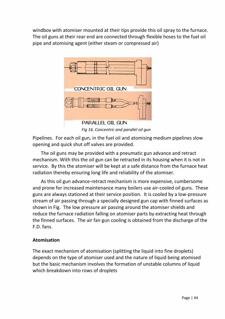
Fuel oils like light diesel oil, (LDO), heavy fuel oil (HFO) or low sulphur heavy stock (LSHS) are used in boilers either as main fuel or supplement fuel. In coal fired boilers fuel oils are used to ignite the coal as well as to supplement the coal firing under various exigencies. These fuel oils are burnt by spray combustion method wherein the oil is split into fine droplets (atomised) and distributed into the furnace in a spray form in a controlled manner. Oil guns either concentric tubes or parallel tubes as shown in Fig Installed through the furnace walls or
Fig 15. Re-Circulating Pattern in H.E.A. Ignition System
Page | 44
windbox with atomiser mounted at their tips provide this oil spray to the furnace. The oil guns at their rear end are connected through flexible hoses to the fuel oil pipe and atomising agent (either steam or compressed air)
Fig 16. Concentric and parallel oil gun
Pipelines. For each oil gun, in the fuel oil and atomising medium pipelines slow opening and quick shut off valves are provided.
The oil guns may be provided with a pneumatic gun advance and retract mechanism. With this the oil gun can be retracted in its housing when it is not in service. By this the atomiser will be kept at a safe distance from the furnace heat radiation thereby ensuring long life and reliability of the atomiser.
As this oil gun advance-retract mechanism is more expensive, cumbersome and prone for increased maintenance many boilers use air-cooled oil guns. These guns are always stationed at their service position. It is cooled by a low-pressure stream of air passing through a specially designed gun cap with finned surfaces as shown in Fig. The low pressure air passing around the atomiser shields and reduce the furnace radiation falling on atomiser parts by extracting heat through the finned surfaces. The air fan gun cooling is obtained from the discharge of the F.D. fans.
Atomisation
The exact mechanism of atomisation (splitting the liquid into fine droplets) depends on the type of atomiser used and the nature of liquid being atomised but the basic mechanism involves the formation of unstable columns of liquid which breakdown into rows of droplets

Page | 45
The process of atomisation can be accomplished in a number of ways in practice, which are usually grouped according to the source of energy used. In boilers fuel oils are atomised mainly by adopting any one of the following two methods.
i) By forcing the oil at high pressure through an orifice. This is called mechanical atomisation or pressure atomisation.
ii) In twin fluid atomisation (Steam or Air atomisation) a stream of gas at high velocity is passed over the liquid surface so that waves are generated which become extended into thin films.
Mechanical/Pressure Atomisation
In a typical pressure atomiser as shown in Fig. oil at a high pressure flows in the centre tube and is discharged through tangential slots in the sprayer plate swirling chamber where the oil rotate at high speed. The swirling oil then passes with undiminished energy through the sprayer plate orifice and escapes as a spray. In this case the hollow conical sheet that is produced emerges from the orifice with a tangential velocity which is sufficiently high to cause an air core throughout the nozzle so produce a hollow cone spray. The advantage of pressure atomisation is it does not require any atomising medium. Hence it may be suitable for lighting up cold boilers. However this atomisers need oil pressure at a range of 40 to 70 kg/cm2 and so need suitable oil pumps. The turn down ratio (the ratio of maximum to minimum fuel flow rate required to produce a stable self-sustained flame) of these atomisers is less compared to other type of atomiser. In power plants these atomisers are used for light oil start up burners only.

Page | 46
Fig 17. Mechanical/Pressure Atomisers
Twin Fluid Atomiser
In this type of atomisers, the atomisation consists of the following stages
i) Formation of thin liquid sheets along the inner walls of an internal mixed atomiser or of free sheets.
ii) Disintegration of these sheets by aerodynamic forces to form ligaments and large droplets to form spray.
Either compressed air or superheated steam will be used as atomising medium to apply aerodynamic force on the oil sheet.
Two types of these atomisers, a) internal mixing b) external mixing are shown in Fig. The atomiser is screwed to a concentric tube oil gun. With an internal mixing atomiser oil flow through the inner tube and atomising medium through outer type. In internal mixing atomiser, the oil and atomising medium impinge within the atomiser and comes out as a spray. Atomisation is accomplished by projecting atomising medium tangentially across the jets of oil and results in the formation of conical spray of finely divided oil after the mixture has left the orifice plate. Here a constant differential pressure is to be maintained between oil and atomising medium. In external mixing atomisers the oil is released into the gas stream at the outlet from the atomiser. A constant pressure of atomising medium is to be maintained for the proper operation of external mixing type atomiser.

Page | 47
In Indian power stations normally compressed air is used for atomising light oil and steam is used for atomising heavy oil.
Flame Scanners
In any boiler, a large quantity of fuel is being admitted to the furnace, the flammable mixture formed in the furnace must be converted into inert at the earliest available time before any appreciable quantity builds up in the furnace. This needs a sustained healthy intensified flame in the furnace. Admission of fuel without flame in furnace leads to furnace explosions. Hence detection of absence of flame is required for any control action to prevent furnace explosion. Firing systems of modern boilers incorporate flame sensing scanners to detect
Fig 18. Internal mixing Atomiser

Page | 48
the flame in the furnace and in the loss of flame to initiate control actions to prevent furnace explosions.
Fundamental Requirements of a Flame Detecting System
Any flame detection system provided in the boiler must meet the following requirements.
- Must be reliable
- Sensible to discern the minimum flame envelope
- Fail safe characteristic to avoid frequent trips.
- Reaction time must be minimum
Flame Scanner Types
The burning process exhibits many characteristics, which can be sensed as indicators of existing flame. In large furnace installations like power boiler furnace, the most practical characteristic to sense the proof of flame is the light emitted by the burning process. The light emission covers a broad spectrum including infrared, visible and ultraviolet spectrums. Sensing any one of these spectrums can be used for flame proving.
Accordingly three basic types of flame scanners are used.
1. Ultraviolet scanners
2. Visible light scanners
3. Infrared scanners.
Further these scanners also utilise the fluctuating intensity (frequency) character of the furnace flames to prove the flame.
Ultra Violet Scanners
In this type, the scanner head located near the burner consists of ultraviolet tube. The special glass envelope has a low attenuation for ultra violet rays. The tube is filled up with helium gas at low pressure. Pure tungsten electrodes are placed inside the tube. When ultraviolet rays emitted by the flame strike these electrodes, they emit electrons proportionate to the ultraviolet radiation. The electron flow through the helium gas is utilised by the scanner electronics to

Page | 49
prove the flame. Each scanner tube is provided with a shutter mechanism, which close the tube at periodical intervals. When the shutter closes the ultraviolet rays are not passed to the tube and so the scanner should sense no flame. This is used for self-testing of the healthiness of the scanner.
As ultraviolet radiation which is abundant in fossil flames is not emitted in significant quantities from other hot bodies of the furnace such as hot refractory, hot metal and hot gases at the temperatures encountered in boiler furnaces, ultraviolet detection will not cause any false detection of flame. However one problem with ultraviolet detection in coal fired boilers is a considerable portion of ultraviolet radiation is absorbed by intervening coal dust before it can reach the scanner. This may result in a false indication of no flame.
Visible Light Scanners
This flame scanner is an optical scanner utilising a fibre optic light guide. It recognises particular characteristics of visible light radiated from the furnace flames. Visible light is directly related to the burning process. It is given off in substantial quantities so that a stable flame cannot be masked by unburnt coal.
The scanner head with a fibre optic light guide is mounted in the windbox. Visible light from the area of combustion as monitored is transmitted through this fibre optic light guide to the electronics system kept outside the boiler. A photodiode in this system converts the light to an electric signal. A blue enhanced silicon photodiode with an integral optical I.R. filter is used as the primary sensor. This boiler mounted components integrated with a remote signal processing card form the flame detection system. They recognise the frequency and intensity levels of the visible light emitted by the furnace flame along with a self-diagnosing no fault in the system to prove the furnace flame
Infrared Scanners
These flame scanners are working on the principle of sensing infrared rays. The flame controller in conjunction with the flame detector monitors coal, oil and gas flames selectively in the near infrared spectral range. The flame monitoring circuit is sensitive only to the evaluation of the flicker frequency and not to the steady infrared radiation from the combustion chamber and glowing boiler wall refractory. It is insensitive to daylight, the system consists of an infrared light receiver located near the burner and a control unit. Infrared scanners are rarely used in coal fired boilers.

Page | 50
Scanner Air
In any type of scanner, the scanner head is located through the wind box and is viewing the furnace, but the components of the scanner head are temperature sensitive and fail normally if this temperature increase above 150oC. Hence to keep the scanner head at a low temperature cold air supplied by scanner air fan will be continuously passed through the scanner guide pipe.
7.8. Oil Firing System Fuel Oil Preparation Filtering the oil, Pumping the oil and heating it are the major preparatory functions. Filtration of oil in one or more stages to remove any dust, dirt, sediments, sledge etc. also forms part of preparation. This renders long trouble free service life to pumps, valves and oil gun atomiser nozzles. Pumping the oil to overcome pressure drop in the long oil supply lines and deliver the oil at required pressure at oil gun tips. LDO:
Sr No Parameters Values
1 Total sulphur 500 mg/kg
2 Ash (% by mass) 0.01
3 Relative density at 15 0C 0.82-0.86
4 Kinematic viscosity (centistokes at 40 0C) 2.0/5.0
5 Max. pour point 3 0C (winter)/ 15 0C (summer)
6 Water (volume percent) 0.10
7 Gross calorific value 10,000 kCal/kg
8 Min. flash point 66 0C
HFO:
Sl.
No. Parameters
Heavy Furnace Oil IS1593-71
Grade HV
Low Sulphur Heavy Stock
(LSHS)
1. Total Sulphur content 4.5% max 1.0% max
2. Gross calorific value (kg) Of the order of 10,000 Of the order of 10,000
3. Flash point (min) 66 oC 93 oC
4 Water content by volume (max) 1.0% 1.0%
Table 3: LDO Parameters

Page | 51
5. Sediment by weight (max) 0.25% 0.25%
6. Asphaltene content by weight (max.) 2.5% 2.5
7. Kinematic viscosity in centistokes at
50 0C (max)
370 500
8. Ash content by weight (max) 0.1% 0.1%
9 Acid(Inorganic) Nil Nil
10. Pour point (max) 24 0C 57 0C
Fuel Oil Atomisation Atomisation is the process of spraying the fuel oil into fine mist, for better mixing of the fuel with the combustion air. While passing through the spray nozzles of the oil gun, the pressure energy of the steam converts into velocity energy, which breaks up the oil stream into fine particles. Poorly atomised fuel oil would mean bigger spray particles, which takes longer burning time, results in carryovers and makes the flame unstable due to low rate of heat liberation and incomplete combustion. Other than pressure, viscosity of the oil is the major parameter which decides upon the atomisation level. For satisfactory atomisation the viscosity shall be 15 to 20 centistokes. Oil Recirculation Before putting in the first burner into service, it is necessary to warm up the long oil supply lines to the burners, so that the oil does not get cooled in the colder pipes and that the oil at correct atomising temperature becomes available at the burners. To achieve this the heated oil is circulated up to the burners and back to the oil tank through oil return lines till adequate oil temperature is reached near the burners. System Vents Fuel oil heaters, strainers and lines are provided with vent cocks or valves on oil and steam sides to get rid of air locks while charging system. System Drains All oil lines are run with a slope of about 0.3 to 0.5% towards drain. Each section of oil line is provided with a drain valve at the lowest point. All drain valves are normally kept closed during operation.
Table 4: HFO Parameters

Page | 52
Oil Temperature Control The result of inadequate heating of oil is "higher oil viscosity" which impairs atomisation at the oil gun, leading to poor flames, sooting, increased carbon loss and finally flame failures. Overheating the oil is also not desirable from the point of thermal cracking of oil. The formed solid carbon particles build up over the heater tubes, and plug up the strainer, intricate passages of control and shut off valves and atomisers. The carbon particles also cause faster atomiser wear out and sparkling in the flame. Oil Burner Design Considerations The essential requirements for an oil burner design are: a) It must completely atomise the oil without -drooling, fouling or clogging. b) The jet must be so shaped that it will completely mix with the air necessary for combustion. c) Maintenance of atomisation over a comparatively wide capacity range. d) Combustion must be complete and excess air at a minimum over the entire operating range. e) A ready accessibility for effecting repairs, thereby minimising burner outage as well as maintenance costs. Air Atomising System The air atomising system uses compressed air at 7 kg/ sq.cm. The quantity of air required depends on design of burner, degree of atomisation required, grade of oil, its pressure and temperature. The air used in the system should be free of condensate. Air atomising systems are not recommended for heavy oil system as they tend to chill the oil and decrease atomisation quality. The guns used in this system have two main components for atomisation. They are: a) Mixing plate b) Spray Plate. The role of mixing plate is to mix the air and oil properly and the role of spray plate is to inject this mixture uniformly into the furnace. Mechanical Atomisation Oil under pressure is supply to the burner gun and enters the atomiser tip through slots cut tangentially to the periphery of the Whirling. The drop pressure is converted into velocity causing the oil to enter the whirling chamber at a very high speed, thus establishing a rapid rotation of the oil in the whirling chamber. Since the mechanical atomisation oil guns are limited in range they are generally selected for boiler operating at fixed loads.

Page | 53
Steam Atomisation This system uses auxiliary steam to assist in the atomisation of the oil. The steam used in this method should be slightly superheated and free of moisture. As in the air atomising system, the steam used for atomising as well as the fuel pass through the tip and into the furnace. The main advantages of steam atomising burners over other are: a) Simplicity of its design b) Initial cost of installation is low c) Low pumping pressure d) Low preheating temperature. The only disadvantage is the steam consumption in burners. Refer the figure below for air / steam atomised oil gun compartment with wind box assembly.
8. Boiler Boiler or the steam generator is the main part in the power generation process. Boiler acts as a medium in which the water is converted into the steam by using the heat released in the process of combustion of coal in the presence of oxygen. Categorization of Boilers Boilers are generally categorized as follows: Steel boilers Fire Tube type Water tube type Horizontal Straight tube Bent tube Natural Circulation Positive Circulation Shell type Cast Iron Boilers Special Design Boilers Nuclear Reactors
The steam generator is a natural circulation, single drum type, corner fired, and natural draft unit of water tube type.
In water tube boiler, boiler feed water flows through the tubes and enters the boiler drum. The circulated water is heated by the combustion of gases and converted into steam at the vapour space in the drum.

Page | 54
These boilers are selected when the steam demands as well as the steam pressure requirements are high as in the case of process cum power boilers.
The features of water tube boilers are:
Forced, induced and balanced draft provisions help to improve combustion efficiency.
Less tolerance for water quality calls for water treatment plant.
Higher thermal efficiency levels are possible. There are many mountings to the boiler, which are compulsory for the safe run of the boiler. Also, there are accessories, which increase the efficiency of the boiler. Arrangement of Main Boiler The illustration given in figure below shows a symbolic arrangement of various accessories of a Boiler. These accessories include 1. Economizer 2. Boiler drum 3. Down Comers 4. Water walls 5. Water wall platen (used for Low Pressure Boilers)
6. Primary super heater 7. Platen super heater 8. Final super heater 9. Reheater 10. Burner 11. Igniters
Boiler Combustion Details
32 direct air burners in 8 layers
Elevation of top row burners: 39780 mm and 20020 mm away from platen
bottom
Elevation of bottom row burner: 26150 mm and 5131 mm from furnace corner
U-OFA air nozzle: 3 layers in the upper part of wind box
17 groups of secondary air damper, 3 groups of over fire damper
20 sets of ignition devices in 5 layers (16 sets HFO (steam atomised) + 4 sets
(air atomised) LDO air igniters)

Page | 55
Fig 19. Boiler Block Diagram
9. Furnace
In a boiler heat energy is released from the fuel by the combustion reaction. The furnace provides the enclosure for combustion confining and isolating it so that combustion is a controlled activity. The furnace is designed for efficient and complete combustion. Though the furnace enclosure can be built in many ways in large capacity power boilers the furnace enclosure is formed by water wall system which has many advantages over the other arrangements.
FURNACE DESIGN
The furnace design is influenced by the following factors:
i) Fuel
ii) Allowable heat loading

Page | 56
a) Surface (EPRS) b) Plan area c) Volumetric
iii) Burner clearance
EFFECT OF FUELS ON FURNACE DESIGN
The major fuels used in the steam generators are coal, oil and gas. The furnace designed for firing pulverised fuels are basically sized to ensure complete combustion with minimum formation of objectionable slag deposits. For coal fired boilers this requirement generally results in a relatively low furnaces wall absorption rates with safe metal temperatures.
In the oil-fired boilers, the combustion can be achieved in a much smaller volume of furnace than a coal fired unit. However this intense combustion process results in very high-localised heat absorption rate within the active burning zone of the furnace. In order to avoid these high heat absorption rates, the furnaces selected for oil firing are increased in size above the minimum required to complete combustion only, to a size that will produce safe furnace wall temperatures.
The combustion characteristics of gas produce a more uniform heat release pattern within the furnace. This allows the use of even smaller furnaces than for oil.
The Fig. illustrates the relative size of units designed for these three fuels at high sub critical pressure levels.
All coals have certain characteristics (Table) which may be used on a relative basis to compare their effect on furnace sizing.
TABLE: COAL CHARACTERISTICS
Total moisture : 15
Ash : 30
Sulphur : 0.5
HHV kcal/Kg : 4500
Ash softening temperature : 1250oC
(At reducing atmosphere)
Sodium content in ash as Na20 : 01

Page | 57
The moisture content in coal affects the design of the boiler in many ways such as combustion gas weight, flue-gas velocities, boiler efficiency, heat transfer rates and low temperature corrosion.
The ash quality and quantity can affect the furnace slagging rate, fouling of super heater, re heater and air heater surfaces, the unburnt carbon loss, the amount of particulate emission discharged to the atmosphere and the capacity of ash handling system.
Fig 20. Comparison of Furnaces for different Fuels

Page | 58
ALLOWABLE HEAT LOADING
The furnace heat loading is a characteristic requirement for each fuel. Normally three basic heat loadings are considered for furnace designs. The EPRS (Effective Projected Radiant Surface) heat loading can be related to the gas temperature leaving the furnace. This gas temperature is very much significant in the case of coal fired boilers. This value should be considerably lower than the initial ash deformation temperature to protect superheaters and re heaters from fouling due to ash deposition. In the case of oil and gas fired boilers this loading will be high, however taking care of the metal temperatures in the water wall and maintaining an optimum gas temperature for the heat transfer in super heater/re heater. This value change from 200,000 to 325,000 kCal/hr/m2 for coal fired boilers and a maximum of 550,000 kCal/hr/m2 for oil and gas fired boilers.
The plan area heat loading can be correlated to the maximum localised heat absorption rate and maximum temperature of products of combustion. In other words, a very high plan area loading may tend the furnace to slag in the case of coal fired boilers and increase the furnace wall temperature in the case of oil and gas fired boilers. The normal value for coal ranges from 3 to 4 million kCal/hr/m2 and for oil and gas a maximum value of 5 million kCal/hr/m2 shall be used.
The volumetric heat loading is an important criterion especially for fuels critical about stabilisation for combustion and low heating value gases. A low value of volumetric heat loading signifies an increased residence time in the furnace for the combustion to complete. The values used for the normal fuels range from 130 to 300 x 103 kcal/hr/m3.
10. Burners
Burners undertake the task of delivering coal and air in a proper proportion,
facilitate ignition energy to the coal air stream, sustain the ignition and provide
a stable flame during the operation, complete the task of combustion and
delivering heat to the intended purpose.
Burners are broadly classified as follows: (1) Tangential Burners (2) Wall Burners (3) Down shot or fan tail burners
Modern Burners are equipped with: (a)Separate flame envelope ports for coal, oil and gas.

Page | 59
(b)Secondary air control to adjust the flame envelops. (c)Ignitors. (d)Flame Scanners to detect the distinct flames in an enclosure. (e) Flame Stabilisers. (f) Flame Analysers
The proportioning of air flow is done based on boiler load, individual burner load, by a series of air dampers. Each of the auxiliary and end air nozzles are provided with louver type regulating dampers, at the air entry to individual air compartment. The damper regulates on elevation basis, in unison, at all corners. The burners maybe tilt able about horizontal, in unison at all elevations and corners. This shifts the flame zone across the furnace height and enables control over steam temperature. Combustion Air Distribution The Combustion air, referred to as Secondary Air, is provided from FD Fans. A portion of secondary air called `Fuel Air', is admitted immediately around the burners (annular space around the oil/gas burners) into the furnace. The rest of the secondary air, called 'Auxiliary Air', is admitted through the auxiliary air nozzles and end air nozzles. The quantity of secondary air (fuel air + auxiliary air) is dictated by boiler load and controlled by FD Fan inlet guide vane regulation.
Burner Clearance
Sufficient height between the top row of fuel nozzles and the furnace outlet must be provided especially in the case of coal fired boilers to obtain proper furnace retention time. This value ranges from 15 to 20 meters for large utility Boiler. In the case of horizontal firing, which is adopted mostly for industrial boilers, the clearances between the burners, between the side walls and burner nose portions should all be properly sized to avoid flame impingement on the walls and also flame embracing which is not desirable from the combustion and heat absorption point of view.
Burner Arrangement
There are 36 pulverised coal burners arranged on the corners at a height of 17 to 38 meters and 20 oil burners. The pulverised coal burners are arranged in such a way that eight mills supply the coal to burners at 4 corners, of the furnace, all the nozzle of the burners are inter linked and cannot be tilted. The oil burners are fed with light diesel oil and heavy fuel oil till boiler load reaches

Page | 60
to about 25%. There are four wind boxes fixed at 4 corners of the furnace. There are 17 nozzles in each wind box 8 for coal and 9 for air. In tangentially fired boilers, four tall wind boxes are arranged at each corner of the furnace. The coal burners are located at different elevations of wind boxes. The numbers of coal nozzles elevations are equivalent to the number of coal mills. The same elevations of coal nozzles at four corners are fed from a single coal mill.
The coal nozzle is sandwiched between air nozzles or compartments. That is, nozzles are arranged between coal nozzles, one below the bottom coal nozzle and above the top coal nozzle. If there are ‘n’ numbers of coal nozzles per corner there will be (n+1) number of air nozzles per corner.
The coal fuel and combustion air streams from these nozzles directed tangential to imaginary circle at the centre of the furnace. This creates turbulent vortex motion of the fuel, air and the hot gases which promotes the mixing, ignition energy availability and thus combustion efficiency.
The air nozzles in between are termed as “Auxiliary air nozzles”, and the topmost and the bottommost air nozzles are termed as “End air nozzles”.
The coal nozzles elevations are designed as A, B, C, D, E, F, G, and H from bottom to top, the bottom end air nozzles as AA, and the top end air nozzles as HH. The auxiliary air nozzles are designated by the adjacent coal nozzles as, like AB, BC, CD, DE, EF, FG, GH and HH from bottom to top.
The four furnace corners are designated as 1, 2, 3 and 4 in clockwise direction looking from the top, and counting front water wall left corner as ‘1’, as shown in the figure below.
Each pair of coal nozzle elevation is served by one elevation of oil burners located in between the auxiliary air nozzles. In this with the eight mills or eight elevations of coal nozzles, there are 20 oil guns arranged in four elevations at auxiliary air nozzles at AB, CD, EF and GH.
Heavy fuel oil can be fired at the oil gun elevations and L.D.O can be fired only in AB elevation. Each oil gun is associated with an igniter arranged at the side.
11. Improving Boiler Efficiency Your boiler probably accounts for the majority, if not all, of your heating fuel bill. If you tend to budget a fixed dollar amount for this fuel bill, you may be interested in knowing that most boiler systems are, at best, 85% efficient with an average efficiency of only 65% to 75%. This means from 25 to 35% of your heating bill is going up the chimney with no appreciable benefit to you. There

Page | 61
are many ways to increase a boiler system's efficiency. These range from ongoing low-cost or no-cost operation and maintenance improvements, to one-time capital improvements. Some proven one-time investments are discussed below. Reduce Excess Air Efficiency Improvement - Up to 5 percentage points. Properly operated boilers require a certain amount (10% to 20%) of excess air to ensure complete combustion. However, operating with too much excess air reduces boiler efficiency by heating up and throwing away this "cushion" of excess air. On the other hand, operating the boiler with no excess air can lead to sooting on the fireside, air pollution, and poor efficiency and even potentially explosive flue gases, so that boiler operators tend to have a cushion of excess air rather than a deficiency. Monitoring the flue gas temperature, oxygen content, and carbon dioxide content allows the operator to minimize this cushion and fine tune the boiler for optimal efficiency under varying ambient and load conditions. Portable or fixed combustion efficiency tests are available from many sources and may be used to manually adjust combustion air quantities. This is typically the only choice for natural draft type boilers and should be performed on a weekly basis. For forced draft boilers, an automatic combustion control system can be added to automatically monitor flue gas combustion and adjust combustion air quantities on an instantaneous basis. Condensate Return Condensate from a steam boiler system is hot mineral free water. Strong consideration should be given to returning all usable condensate in order to minimize the use of cold makeup water which must be heated prior to entering the boiler. An added benefit will be the decreased use of chemicals and improved boiler surfaces. This will reduce corrosion (which can lead to early failure) and/or the build-up of scale (which can hurt boiler efficiency). Blowdown Heat Recovery Efficiency Improvement - Up to 2 percentage points. Blowdown of boilers to reduce the sludge and solid content allows heat to go down the drain. The amount of blowdown should be minimized by following a good water treatment program. Installing a heat exchanger in the blowdown line allows this waste heat to be used in preheating makeup and feed water.
Page | 62
Heat recovery is most suitable for continuous blowdown operations which in turn provides the best water treatment program. Exhaust Heat Recovery A device like the one shown below can be attached to the flue to recover a portion of the exhausted heat. This heat can be used to preheat boiler make-up water. Take care not to extract so much heat that the flue gases condense (causing corrosion). Preheat Combustion Air Efficiency Improvement - Up to 1 percentage point. If you have a large temperature difference (20° to 40°) between your boiler intake air location and the ceiling of your boiler room and this hot air is a result of boiler and stack losses, you can increase your boiler efficiency by either extending the intake upwards or forcing the hot air down. Both options may require a fan and ductwork. If the hot air is due to boiler wall losses, you may want to consider insulating the boiler. Upgrade Boilers with Energy-Efficient Burners Background The purpose of the burner is to mix molecules of fuel with molecules of air. A boiler will run only as well as the burner performs. A poorly designed boiler with an efficient burner may perform better than a well-designed boiler with a poor burner. Burners are designed to maximize combustion efficiency while minimizing the release of emissions. A power burner mechanically mixes fuel and combustion air and injects the mixture into the combustion chamber. All power burners essentially provide complete combustion while maintaining flame stabilization over a range of firing rates. Different burners, however, require different amounts of excess air and have different turndown ratios. The turndown ratio is the maximum inlet fuel or firing rate divided by the minimum firing rate. An efficient natural gas burner requires only 2% to 3% excess oxygen, or 10% to 15% excess air in the flue gas, to burn fuel without forming excessive carbon monoxide. Most gas burners exhibit turndown ratios of 10:1 or 12:1 with little or no loss in combustion efficiency. Some burners offer turndowns of 20:1 on oil and up to 35:1 on gas. A higher turndown ratio reduces burner starts, provides better load control, saves wear-and-tear on the burner, reduces refractory wear, reduces purge-air requirements, and provides fuel savings.

Page | 63
Efficient Burner Technologies An efficient burner provides the proper air-to-fuel mixture throughout the full range of firing rates, without constant adjustment. Many burners with complex linkage designs do not hold their air-to-fuel settings over time. Often, they are adjusted to provide high excess air levels to compensate for inconsistencies in the burner performance. An alternative to complex linkage designs, modern burners are increasingly using servo- motors with parallel positioning to independently control the quantities of fuel and air delivered to the burner head. Controls without linkage allow for easy tune-ups and minor adjustments, while eliminating hysteresis, or lack of retrace ability, and provide accurate point-to-point control. These controls provide consistent performance and repeatability as the burner adjusts to different firing rates. Alternatives to electronic controls are burners with a single drive or jackshaft. Avoid purchasing standard burners that make use of linkages to provide single-point or proportional control. Linkage joints wear and rod-set screws can loosen, allowing slippage, the provision of sub-optimal air-to-fuel ratios, and efficiency declines. Applications Consider purchasing a new energy-efficient burner if your existing burner is cycling on and off rapidly. Rotary-cup oil burners that have been converted to natural gas use are often inefficient. Determining the potential energy saved by replacing your existing burner with an energy efficient burner requires several steps. First, complete recommended burner-maintenance requirements and tune your boiler. Conduct combustion efficiency tests at full- and part-load firing rates. Then, compare the measured efficiency values with the performance of the new burner. Most manufacturers will provide guaranteed excess O2, CO, and NOx levels.
Optimisation of Combustion Air Enhances Boiler Efficiency
The main purpose of a boiler is to convert the chemical energy of a fuel into heat energy by means of combustion and then to transfer this heat to steam as efficiently and cost effectively as possible. Gas-fired boiler thermal efficiency is mostly dependant on the waste heat that leaves the boiler via the stack.

Page | 64
The amount of heat lost in the exhaust gas is governed by the temperature of the gas and the amount of flue gas going up the stack. Thus improvement in thermal efficiency can be achieved by: • reducing the flue gas temperature, and • optimising the amount of combustion air. There is some interplay between these two factors, but they can be viewed as follows: Reducing Flue Gas Temperature The flue gas temperature is determined by the boiler designer. This is a function of the installed heating surface and how effectively this area has been arranged by the designer using heat transfer enhancing techniques. There is little an operator can do to reduce the flue gas temperature of a given boiler other than keeping the boiler clean. When gas-firing, a reduction of the flue gas temperature of 25°C will improve the thermal efficiency by 1%. Optimisation of Combustion Air The amount of flue gas generated in the combustion process is determined by the amount of fuel burned and the volume of combustion air consumed. The purpose of the burner combustion control system is to ensure that the right amount of oxygen is available for complete combustion at any given load. Oxygen for combustion is usually supplied in the form of atmospheric air which contains 21% oxygen. By measuring the oxygen content in the flue gas leaving the boiler, it is possible to determine the amount of air used. Burners are commissioned by setting up these flue gas oxygen levels to the burner manufacturer’s specifications. Oxygen levels in the flue gas are typically in the range of 2% to 4.5%. When gas-firing, a reduction of the flue gas oxygen content of 1% will increase the thermal efficiency by 0.3%, provided combustion is still complete (i.e. no significant CO formation or unburnt hydrocarbons present).

Page | 65
Fig 21. Effect of excess air on efficiency
Control of Combustion Air Most modern burner control systems are microprocessor based and utilize servo motors to vary the air and fuel inputs to the burner. These combustion controllers incorporate some form of excess air curve or lookup table to ensure the correct air/ fuel ratio is maintained. To cater for variations in ambient air temperature and fuel composition, the flue gas oxygen levels are set slightly higher than ideal, as it is better to have too much oxygen than too little under any firing condition. Insufficient oxygen will result in unreleased chemical energy of partially completed chemical reactions like CO formation. Accurate, repeatable and safe operation over a wide turndown is possible with such controllers and servo motors. To achieve optimum combustion settings, John Thompson Enviropac boilers are supplied with Lamtec combustion controllers as standard. Enhanced Control with O2 and CO Measurement An O2 sensor in the flue gas can be added to the combustion controller to achieve a slightly lower pre-set excess air curve. This system will account for variations in fan performance (due to changes in ambient air temperature and pressure) as well as variations in fuel composition. Efficiency improvements of 0.5% to 1% can be expected with such systems. By adding an additional CO sensor, the Lamtec combustion controller can self-learn the optimum shape of the burner excess air curve. This self-learning is achieved by the controller constantly testing the minimum air/fuel ratio by automatically cutting back on air flow in small increments and checking for the presence of CO, an indication that the minimum possible setting has been reached for the prevailing conditions. With CO control, O2 levels below 2% are possible.
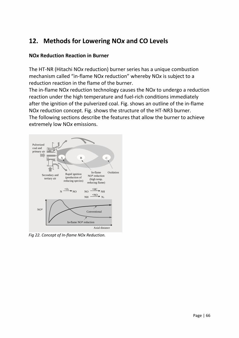
Page | 66
12. Methods for Lowering NOx and CO Levels NOx Reduction Reaction in Burner The HT-NR (Hitachi NOx reduction) burner series has a unique combustion mechanism called “in-flame NOx reduction” whereby NOx is subject to a reduction reaction in the flame of the burner. The in-flame NOx reduction technology causes the NOx to undergo a reduction reaction under the high temperature and fuel-rich conditions immediately after the ignition of the pulverized coal. Fig. shows an outline of the in-flame NOx reduction concept. Fig. shows the structure of the HT-NR3 burner. The following sections describe the features that allow the burner to achieve extremely low NOx emissions.
Fig 22. Concept of In-flame NOx Reduction.
Pulverized coal and p rimary air
Secondary and tertiary air
Rapid ignition production of (
reducing species)
A B C
In-flame NO x reduction
( high temp. reducing flame)
Oxidation
N NO NO NH NH N 2
+ O 2
+ NO
Conventional
In-flame NO x reduction
Axial distance
NO x
+ HC

Page | 67
Fig 23. The Structure of HT-NR3 Burner.
1) Expansion of recirculation zone after flame stabilizing ring A rapid ignition of pulverized coal just after the fuel nozzle exit is important for maintaining the stable flame that enhances the operation of inflame NOx reduction. Establishing a flame at the early stages of combustion promotes consumption of oxygen and enlarges the reduction zone where the oxygen concentration is low. In the HT-NR3 burner, the recirculation zone formed at the exit of fuel nozzle is enlarged by attaching a baffle plate to the flame stabilizing ring fitted at the exit of the fuel nozzle to redirect the secondary air jets that blow air from around the circumference of the fuel so that they blow in a more outward direction. The rapid heating of the pulverized coal in the region of hot gas that is retained in the recirculation zone enhances ignition. 2) Concentration of pulverized coal The concentration of the pulverized coal is a critical factor in enhancing ignition. The denser the pulverized coal, the shorter the distance between coal particles. This promotes rapid ignition and flame stability through better flame propagation. The PC (pulverized coal) concentrator has the shape of an artillery shell and is installed in the fuel nozzle of the HT-NR3 burner. The pulverized coal and primary air both tend to move closer to the inner wall of the fuel nozzle in the parallel part of the PC concentrator but the difference in momentum between the pulverized coal and air at the exit of the fuel nozzle means that only the air returns to the central zone. As a result, pulverized coal is concentrated around the flame stabilizing ring located at the exit of the fuel nozzle.
Pulverized coal and p rimary air
Secondary and tertiary air
Rapid ignition production of (
reducing species)
A B C
In-flame NO x reduction
( high temp. reducing flame)
Oxidation
N NO NO NH NH N 2
+ O 2
+ NO
Conventional
In-flame NO x reduction
Axial distance
NO x
+ HC

Page | 68
3) Optimum flow pattern of outer air Tertiary air expands to the outside at the burner exit and this forms a reducing zone with fuel-rich conditions in the flame. The tertiary air then returns to the centre of the flame after the NOx reduction reaction has completed and mixes with the flame to promote further combustion. In the HT-NR3 burner, a simple guide sleeve effectively separates this reaction from the outer air. The development of HT-NR burner series succeeded in lowering NOx emissions as shown in Fig.
Fig 24. NOx Performance of HT-NR Series.
Lower NOx through Improved TSC Ports Use of TSC in the burners further reduces NOx. In this method, a combustion reaction under air-poor conditions is promoted between the burners and the TSC ports with the reaction being completed between the TSC ports and the furnace exit. It is well known that increasing the distance (HR) between the burners and TSC ports helps lower NOx levels. However, assuming the same furnace height, making HR longer shortens the distance between the TSC ports and the furnace exit, resulting in lower combustion efficiency due to higher CO and UBC (unburned carbon). This trade-off relationship between NOx and CO and UBC is a problem to be resolved. To overcome this trade-off, Hitachi has developed new multi-stage TSC ports and succeeded in promoting a combining of the TSC air and unburned gas. This new technology allows the same level of CO reduction to be achieved within a shorter distance.
100
50
0
Two-stage combustion
Circular burn er
HT-NR
HT-NR2
HT-NR3
With Without
Coal properties Fuel ratio: 2.2 Nitrogen: 1.8wt%

Page | 69
This can even prevent an increase in CO when the reducing zone is enlarged to lower NOx levels. That is, the development of this new combustion method simultaneously lowers levels of both NOx and CO. Fig. shows the difference between the concepts used in the conventional and new combustion methods.
Fig 25. Concept of New TSC System.
The new multi-stage TSC port system requires at least two TSC port stages. Each TSC port tier corresponds to a particular region of the furnace and supplies air based on the distribution of unburned gas so as to promote mixing of unburned gas and air. Enlarging the distance between the burners and TSC ports also helps lower the level of thermal NOx produced in the high-temperature combustion region and this complements the lower levels of fuel NOx achieved by enlarging the reducing zone. “Thermal NOx” is the generic term for nitrogen oxides produced from nitrogen in the air at high temperature. The temperature of the furnace gas gradually decreases with the height of the furnace due to cooling through radiation to the furnace walls. By optimizing the distance between burners and TSC ports, the furnace gas temperature at the TSC port locations can be controlled so that thermal NOx does not increase.
Conventional New method
Oxidizing zone
(2) TSC ports ( Two-stage )
(1) Burners ( HT-NR 3)
(3) Enlarged reducing
zone
TSC p orts

Page | 70
13. CONCLUSION
Combustion is the basic process by which heat is released in furnace and requires lot of efforts for optimisation. The first principle in combustion optimisation is to provide more oxygen than is theoretically needed to ensure that all the fuel burns. The second principle is to not use too much oxygen. The correct amount of oxygen requires three types of measurement: first, active control of air and fuel flow; second, offgas oxygen measurement; and third, measurement of offgas combustibles. For each heating process there exists an optimum condition of minimal offgas heat loss with acceptable level of combustibles concentration. Minimising excess oxygen pays an additional benefit: for a given offgas temperature, the NOX level is lowest when excess oxygen is kept lowest. Adherence to these two principle is furthered by making material and heat balances on the combustion process. The material balance directly relates the air/fuel ratio to the percentage of O2 in the combustion gas. The heat balance relates the heat available for the charge to the overall net heat produced by fuel combustion. Additional material and heat balances can be made to quantify the thermal advantage from preheating the combustion air, or enriching it in oxygen. Attention should be directed to ensuring that the burners receives an adequate supply of air to the combustion zone for complete burning to occur. It is well known that carbon monoxide poisoning (resulting from improperly operated or installed combustion equipment) causes more fatalities and illness during the course of one year than the combined effects of the more dramatic failures of pressure vessel and combustion explosions. Thus it is important that the maintenance, operation and inspection of the entire fuel-burning system are performed with the same diligence that is often directed to the maintenance, operation and inspection of the pressure vessel itself. Combustion and pollutant formation are inseparable processes. Because of the central role of combustion in fossil fuel utilisation for the foreseeable future, major efforts are being made to ameliorate the environmental effects. New clean combustion technologies are being developed based on the better understanding of the physical-chemical bases of pollutant formation and emission from flames and design protocols are formulated for the translation of the scientific results to industrial design.

Page | 71
14. References Wikipedia
Materials from adani power Maharashtra limited
Information from adani power.com
Information related to combustion process in power plants on internet.
Mr. Richard Bennet, Process Heating magazine, September 1997.
www.ntpc.co.in
www.bhel.co.in
“Boiler Operation,” American Boiler Manufacturers Assn. 1998.


![[DRAFT, PRE-FINAL OR FINAL] REPORT - OECD](https://static.fdocuments.us/doc/165x107/5ec770f8c7c9f9670a3f7375/-draft-pre-final-or-final-report-.jpg)