
Final draft ETSI EN 301 649 V0.5 6 Final draft ETSI EN 301 649 V0.5.1 (1999-11) 11.2.3 FU10c 62 11.3...
169
Final draft ETSI EN 301 649 V0.5.1 (1999-11) European Standard (Telecommunications series) Digital Enhanced Cordless Telecommunications (DECT); DECT Packet Radio Service (DPRS)
-
Upload
truongkhue -
Category
Documents
-
view
218 -
download
1
Transcript of Final draft ETSI EN 301 649 V0.5 6 Final draft ETSI EN 301 649 V0.5.1 (1999-11) 11.2.3 FU10c 62 11.3...
Final draft ETSI EN 301 649 V0.5.1 (1999-11)European Standard (Telecommunications series)
Digital Enhanced Cordless Telecommunications (DECT);DECT Packet Radio Service (DPRS)
ETSI
Final draft ETSI EN 301 649 V0.5.1 (1999-11)2
ReferenceDEN/DECT-020159 (f9o001oo.PDF)
KeywordsData, DECT, mobility, profile, radio
ETSI
Postal addressF-06921 Sophia Antipolis Cedex - FRANCE
Office address650 Route des Lucioles - Sophia Antipolis
Valbonne - FRANCETel.: +33 4 92 94 42 00 Fax: +33 4 93 65 47 16
Siret N° 348 623 562 00017 - NAF 742 CAssociation à but non lucratif enregistrée à laSous-Préfecture de Grasse (06) N° 7803/88
Individual copies of this ETSI deliverablecan be downloaded from
http://www.etsi.orgIf you find errors in the present document, send your
comment to: [email protected]
Important notice
This ETSI deliverable may be made available in more than one electronic version or in print. In any case of existing orperceived difference in contents between such versions, the reference version is the Portable Document Format (PDF).In case of dispute, the reference should be the printing on ETSI printers of the PDF version kept on a specific network
drive within ETSI Secretariat.
Copyright Notification
No part may be reproduced except as authorized by written permission.The copyright and the foregoing restriction extend to reproduction in all media.
© European Telecommunications Standards Institute 1999.All rights reserved.
ETSI
Final draft ETSI EN 301 649 V0.5.1 (1999-11)3
Contents
Intellectual Property Rights..............................................................................................................................11
Foreword...........................................................................................................................................................11
1 Scope ......................................................................................................................................................12
2 References ..............................................................................................................................................12
3 Definitions, symbols and abbreviations .................................................................................................133.1 Definitions ........................................................................................................................................................133.4 Symbols ............................................................................................................................................................143.3 Abbreviations ...................................................................................................................................................15
4 Description of services...........................................................................................................................164.1 Data services structure......................................................................................................................................164.2 Service objectives.............................................................................................................................................184.3 Service definitions ............................................................................................................................................184.3.1 PHL service definitions...............................................................................................................................184.3.2 MAC service definitions .............................................................................................................................184.3.3 DLC service definitions ..............................................................................................................................204.3.4 NWK feature definitions.............................................................................................................................214.3.5 Application service definitions ...................................................................................................................234.3.6 Distributed Communication ........................................................................................................................23
5 PHL requirements ..................................................................................................................................23
6 MAC layer requirements........................................................................................................................236.1 MAC services ...................................................................................................................................................236.2 MAC service to procedure mapping.................................................................................................................24
7 DLC-layer requirements.........................................................................................................................257.1 DLC services ....................................................................................................................................................257.2 DLC feature to procedure mapping ..................................................................................................................26
8 NWK layer requirements .......................................................................................................................278.1 NWK features...................................................................................................................................................288.2 NWK feature to procedure mapping.................................................................................................................298.3 Application features..........................................................................................................................................318.4 Application feature to procedure mapping .......................................................................................................328.5 Distributed Communications ............................................................................................................................32
9 Management Entity Requirements .........................................................................................................329.1 Introduction ......................................................................................................................................................329.2 Description of the DPRS operation principles..................................................................................................339.2.1 General........................................................................................................................................................339.2.2 Service class 1.............................................................................................................................................339.2.3 Service class 2.............................................................................................................................................339.3 Resource and physical connection management...............................................................................................349.3.1 Requirements applicable to the Fixed Part (FP) .........................................................................................349.3.1.1 Conditions for resumption and management procedures.......................................................................349.3.1.1.1 General ............................................................................................................................................349.3.1.1.2 ME procedures for FT initiated connection resumption. .................................................................349.3.1.2 Connection Suspension conditions........................................................................................................359.3.1.2.1 General ............................................................................................................................................359.3.1.2.2 Connection suspension due to no data activity ................................................................................359.3.1.2.3 Connection suspension due to violation of the minimum number of bearers (MAC Bandwidth
command) ........................................................................................................................................359.3.1.2.4 Connection suspension by loss of all received bearers ....................................................................359.3.1.3 Activation of Fast Scan mode after Connection suspension..................................................................369.3.1.4 Conditions for Bandwidth modification ................................................................................................36
ETSI
Final draft ETSI EN 301 649 V0.5.1 (1999-11)4
9.3.1.4.1 General ............................................................................................................................................369.3.2 Requirements applicable to the Portable Part (PP) .....................................................................................369.3.2.1 Conditions for connection resumption ..................................................................................................369.3.2.1.1 Procedure for PT initiated Connection resumption..........................................................................369.3.2.1.2 "RFP-busy-for-data" flag.................................................................................................................369.3.2.1.3 Waiting time for collision avoidance after deactivation of "RFP-busy-for-data" flag .....................379.3.2.1.4 Bandwidth after resumption.............................................................................................................379.3.2.1.5 Resumption rejection by the FP.......................................................................................................379.3.2.2 Conditions for Connection Suspension .................................................................................................379.3.2.2.1 General ............................................................................................................................................379.3.2.2.2 Connection suspension due to no data activity ................................................................................379.3.2.2.3 Connection suspension due to violation of the minimum number of bearers (MAC Bandwidth
command) ........................................................................................................................................379.3.2.2.4 Connection suspension by loss of all received bearers ....................................................................389.3.2.2.5 Activation of fast scan mode after Connection suspension..............................................................389.3.2.3 Conditions for Bandwidth modification ................................................................................................389.3.2.3.1 General ............................................................................................................................................389.4 Logical Connection management .....................................................................................................................389.4.1 Requirements for class 1 devices ................................................................................................................389.4.2 Requirements for class 2 devices ................................................................................................................389.4.2.1 General Description ..............................................................................................................................389.4.2.2 Normal procedures of virtual call set-up and release ............................................................................399.4.2.3 Abnormal release of Virtual Calls .........................................................................................................399.4.2.4 Release of Logical Connection..............................................................................................................399.4.2.5 The handshake (stay alive) procedure ...................................................................................................39
10 MAC layer procedures ...........................................................................................................................4010.1 General .............................................................................................................................................................4010.1.1 Frame and multiframe structure ..................................................................................................................4010.1.2 Bit mappings ...............................................................................................................................................4010.1.3 Time multiplexers .......................................................................................................................................4010.1.5 Scrambling..................................................................................................................................................4010.1.6 Error control ...............................................................................................................................................4010.1.7 A-tail identifications ...................................................................................................................................4010.1.8 B-field identifications .................................................................................................................................4010.1.9 RFP idle receiver scan sequence.................................................................................................................4010.1.10 PT receiver scan sequence ..........................................................................................................................4010.1.11 PP states and state transitions .....................................................................................................................4010.1.12 Identities .....................................................................................................................................................4110.2 Non continuous broadcast ................................................................................................................................4110.2.1 Request for specific Q-channel information................................................................................................4110.2.2 Request for a new dummy...........................................................................................................................4110.3 Downlink broadcast..........................................................................................................................................4110.3.1 NT messages ...............................................................................................................................................41
10.3.2 QT messages ...............................................................................................................................................42
10.3.2.1 QT - static system information ..............................................................................................................42
10.3.2.2 QT - FP capabilities ..............................................................................................................................43
10.3.2.2.1 Standard FP Capabilities .................................................................................................................4310.3.2.2.2 Extended FP Capabilities.................................................................................................................4310.3.2.3 Multiframe number................................................................................................................................4410.3.2.4 QT - SARI list contents .........................................................................................................................44
10.4 Paging broadcast...............................................................................................................................................4510.4.1 Paging message formats..............................................................................................................................4510.4.1.1 long or full page message format ..........................................................................................................4510.4.1.2 short page message format ....................................................................................................................4610.4.1.3 Zero length page message format ..........................................................................................................4610.4.1.4 MAC resume page message format .......................................................................................................4710.4.2 MAC layer information in zero and short length paging messages.............................................................4710.4.3 FP paging procedure ...................................................................................................................................47
ETSI
Final draft ETSI EN 301 649 V0.5.1 (1999-11)5
10.4.4 PP paging procedure (Detection of paging message in idle locked mode) .................................................4710.5 Logical Connection Setup ................................................................................................................................4810.6 Logical Connection Release .............................................................................................................................4810.7 Connection Modification..................................................................................................................................4810.7.1 Bandwidth negotiation ................................................................................................................................4810.7.2 Bandwidth modification..............................................................................................................................5010.7.3 Suspend.......................................................................................................................................................5010.7.4 Resume .......................................................................................................................................................5010.8 Physical Connection Setup ...............................................................................................................................5010.8.1 Single bearer physical connection setup .....................................................................................................5010.8.2 Multibearer Physical Connection setup.......................................................................................................5110.9 Physical Connection Release............................................................................................................................5110.10 Bearer Setup .....................................................................................................................................................5110.10.1 Single duplex bearer setup ..........................................................................................................................5110.10.1.1 PT initiated Single duplex bearer setup.................................................................................................5210.10.1.2 FT initiated Single duplex bearer setup.................................................................................................5210.10.1.3 Usage of channel list messages for single duplex bearer setup .............................................................5310.10.2 Double simplex bearer setup.......................................................................................................................5310.11 Bearer Release..................................................................................................................................................5410.11.1 Unacknowledged release.............................................................................................................................5410.11.2 Acknowledged release ................................................................................................................................5510.11.3 Fast release..................................................................................................................................................5510.12 Advanced connection handover........................................................................................................................5510.13 I-channel operation...........................................................................................................................................5610.13.1 IP-error-detect mode ...................................................................................................................................5610.13.2 IP-error-correct mode .................................................................................................................................5610.13.2.1 Unilateral jump......................................................................................................................................5610.13.2.2 Bearer reset ...........................................................................................................................................5610.13.3 Connectionless SIP mode ...........................................................................................................................56
10.14 C-channel operation..........................................................................................................................................5710.14.1 CS-channel..................................................................................................................................................57
10.14.2 CF-channel..................................................................................................................................................57
10.15 Encryption ........................................................................................................................................................5710.15.1 Encryption process - initialization and synchronization..............................................................................5710.15.2 Encryption mode control.............................................................................................................................5710.15.2.1 MT message ..........................................................................................................................................5710.15.2.2 PT procedure for enabling encryption...................................................................................................5710.15.2.2 PT procedure for disabling encryption..................................................................................................5810.15.3 Handover encryption process......................................................................................................................5810.16 Quality control..................................................................................................................................................5810.16.1 RFPI handshake ..........................................................................................................................................5810.16.2 PT frequency correction..............................................................................................................................5810.16.3 Bearer quality report ...................................................................................................................................5810.16.4 Bearer and connection control ....................................................................................................................5910.16.5 A-CRC handshake.......................................................................................................................................5910.17 Physical channel selection ................................................................................................................................5910.18 Bearer replacement...........................................................................................................................................5910.19 Bearer handover request ...................................................................................................................................6010.20 Gf-channel ........................................................................................................................................................6010.20.1 Gf-channel data...........................................................................................................................................60
11 DLC layer procedures ............................................................................................................................6011.1 LU10 Enhanced Frame RELay service (EFREL).............................................................................................6011.1.1 Window size ...............................................................................................................................................6011.1.2 U-plane transmission class 2.......................................................................................................................6111.1.2.1 Sending side procedures........................................................................................................................6111.1.2.2 Receiving side procedure ......................................................................................................................6111.2 FU 10 framing (FU10a, FU10b, FU10c) ..........................................................................................................6111.2.1 FU10a .........................................................................................................................................................6111.2.2 FU10b .........................................................................................................................................................61
ETSI
Final draft ETSI EN 301 649 V0.5.1 (1999-11)6
11.2.3 FU10c .........................................................................................................................................................6211.3 Class A operation .............................................................................................................................................6211.3.1 Class A link establishment ..........................................................................................................................6211.3.1.1 Lower Layer Management Entity (LLME) establishment of a MAC connection..................................6211.3.2 Class A acknowledged information transfer ...............................................................................................6411.3.3 Class A link release.....................................................................................................................................6411.3.4 Class A link re-establishment......................................................................................................................6411.4 Class U operation .............................................................................................................................................6411.4.1 Class U use of LLN for unacknowledged information transfer...................................................................6411.4.2 Class U link establishment ..........................................................................................................................6411.4.3 Class U unacknowledged information transfer ...........................................................................................6511.4.4 Class U unacknowledged release ................................................................................................................6511.5 Lc frame delimiting and sequencing service.....................................................................................................6511.5.1 CS-channel fragmentation and recombination ............................................................................................65
11.5.2 CF-channel fragmentation and recombination ............................................................................................65
11.5.3 Selection of logical channels (CS and CF)..................................................................................................65
11.6 Broadcast Lb service ........................................................................................................................................6511.6.1 Normal broadcast........................................................................................................................................6511.6.2 Expedited broadcast....................................................................................................................................6711.7 Connection handover........................................................................................................................................6711.7.1 Class A connection handover......................................................................................................................6711.7.1.1 Voluntary handover...............................................................................................................................6811.7.1.2 Associated procedure ............................................................................................................................6811.7.1.2.1 LLME connection handover management .......................................................................................6811.7.1.3 Exceptional case....................................................................................................................................6811.7.1.3.1 Receipt of a request for link release.................................................................................................6811.8 Connection modification ..................................................................................................................................6811.9 Encryption switching ........................................................................................................................................7011.9.1 Associated procedure..................................................................................................................................7011.9.1.1 Providing Encryption key to the MAC layer .........................................................................................7011.9.2 Exceptional cases........................................................................................................................................7011.9.2.1 Encryption fails .....................................................................................................................................7011.9.2.2 Connection handover of ciphered connections......................................................................................70
12 NWK layer procedures...........................................................................................................................7112.1 Outgoing call request........................................................................................................................................7112.2 Incoming call request........................................................................................................................................7112.3 Terminal capability indication..........................................................................................................................7212.4 Internal call keypad ..........................................................................................................................................7212.5 Call Resources/Parameters negotiation ............................................................................................................7212.5.1 Default values .............................................................................................................................................7812.6 Bandwidth Change ...........................................................................................................................................8012.6.1 Associated procedures ................................................................................................................................8112.6.1.1 Timer F/P <CC_service> management .................................................................................................8112.6.2 Exceptional cases........................................................................................................................................8112.6.2.1 Service change request is rejected.........................................................................................................8112.6.3 Examples.....................................................................................................................................................8212.7 Connection Reversal.........................................................................................................................................8212.8 IWU-attributes change......................................................................................................................................8312.9 Dynamic Parameters Allocation .......................................................................................................................8412.10 Cipher-switching initiated by PT......................................................................................................................8912.11 Temporary Identity Assign ...............................................................................................................................8912.11.1 Associated procedures ................................................................................................................................9012.11.1.1 Timer F-<MM_ident.1> management...................................................................................................9012.11.2 Exceptional cases........................................................................................................................................9012.11.2.1 PT rejects the identity assignment .........................................................................................................9012.12 Indirect FT initiated link establishment ............................................................................................................9112.13 Fast paging .......................................................................................................................................................9112.14 Collective and Group Ringing ..........................................................................................................................9212.15 Direct FT initiated link establishment ..............................................................................................................92
ETSI
Final draft ETSI EN 301 649 V0.5.1 (1999-11)7
12.15.1 Exceptional case .........................................................................................................................................9312.15.1.1 Link establishment failure .....................................................................................................................9312.16 Resume Paging .................................................................................................................................................9312.17 Broadcast attributes management .....................................................................................................................9412.18 U-plane handling ..............................................................................................................................................9512.19 Management of MM procedures ......................................................................................................................96
Annex A (normative): Operating parameters 97
A.1 ME operating parameters .......................................................................................................................97A.1.1 Constants (applicable to class 1 and class 2 devices) .......................................................................................97A.1.2 Equations..........................................................................................................................................................97A.1.2.1 Waiting time for collision avoidance (WtA)...............................................................................................97A.1.2.1.1 Description ............................................................................................................................................97A.1.2.1.2 Formula .................................................................................................................................................97A.1.2.2 Waiting time for congestion avoidance (WtB) ...........................................................................................97A.1.2.2.1 Description ............................................................................................................................................98A.1.2.2.2 Formula .................................................................................................................................................98A.1.3 Variable parameters (class 2 systems only) ......................................................................................................98A.1.3.1 Parameters set by the FP (class 2 systems only) .........................................................................................98A.1.3.2 Negotiable parameters between FP and PP (class 2 systems only) .............................................................99A.1.3.2.1 Conditions of negotiation ......................................................................................................................99
A.2 Configuration capabilities for class 1 devices .......................................................................................99
Annex B (normative): Interworking conventions for the Frame Relay (FREL) service 100
B.1 Scope of this annex ..............................................................................................................................100B.1.1 Typical configuration for the Frame Relay Service........................................................................................100
B.2 Specific codings for mobility class 2 ...................................................................................................101B.2.1 IWU-Attribute coding ....................................................................................................................................101B.2.1.1 Profile subtype byte (byte 6) of <<IWU-attributes>>...............................................................................102B.2.1.1.1 ISO 8802-3 (Ethernet).........................................................................................................................102B.2.1.1.2 ISO 8802-5 (Token-Ring) ...................................................................................................................102B.2.1.1.3 Internet Protocol..................................................................................................................................102B.2.2 IWU attributes implemented...........................................................................................................................103
B.3 Generic Frame Relay service interworking conventions .....................................................................103B.3.1 DLC U-plane service ......................................................................................................................................103B.3.2 SDU checksum ...............................................................................................................................................103B.3.3 Transmission bit order....................................................................................................................................103B.3.4 Support of SDU size.......................................................................................................................................103B.3.5 SIP connectionless downlink..........................................................................................................................104
B.4 ISO 8802-3 (Ethernet) ..........................................................................................................................104B.4.1 Typical configuration .....................................................................................................................................104B.4.1.1 Examples of implementation of the external transport network................................................................104B.4.2 Specific interworking conventions .................................................................................................................104B.4.2.1 Use of the connectionless downlink SIP service. ................................................................................105
B.4.2.2 Special conventions for mobility class 1 systems .....................................................................................105
B.5 IEE 802-5 (Token Ring).......................................................................................................................105B.5.1 Typical configuration .....................................................................................................................................105B.5.1.1 Examples of implementation of the external transport network................................................................105B.5.2 Specific interworking conventions .................................................................................................................106B.5.2.1 Special conventions for mobility class 1 systems .....................................................................................106B.5.2.2 Use of the connectionless downlink SIP service.......................................................................................106
B.6 Internet protocol ...................................................................................................................................107B.6.1 Typical configuration .....................................................................................................................................107B.6.1.1 Examples of implementation of the external transport network................................................................107B.6.2 Specific interworking conventions .................................................................................................................107
ETSI
Final draft ETSI EN 301 649 V0.5.1 (1999-11)8
B.6.2.1 Special conventions for mobility class 1 systems .....................................................................................107
B.7 Point-to-Point Protocol.........................................................................................................................108B.7.1 Typical configuration .....................................................................................................................................108B.7.1.1 Examples of implementation of the external transport network................................................................108B.7.2 Specific interworking conventions............................................................................................................108B.7.2.1 Special conventions for mobility class 1 systems .....................................................................................108
Annex C (normative): Interworking conventions character-oriented services 109
C.1 Scope of this annex ..............................................................................................................................109C.1.1 Scenario A......................................................................................................................................................111C.1.2 Scenario B.................................................................................................................................................111
C.2 Specific coding for mobility class 2.....................................................................................................112C.2.1 IWU-Attribute coding ....................................................................................................................................112C.2.2 Default-values.................................................................................................................................................114C.2.3 Negotiation of the V.24-parameters ...............................................................................................................114
C.3 Generic interworking conventions .......................................................................................................115C.3.1 PAD functionality...........................................................................................................................................115C.3.1.1 Character formatting .................................................................................................................................115C.3.2 Support of SDU size.......................................................................................................................................115
C.4 V.24 circuits .........................................................................................................................................116C.4.1 General ...........................................................................................................................................................116C.4.2 Encapsulation .................................................................................................................................................116C.4.2.1 Description................................................................................................................................................116C.4.2.2 Framing.....................................................................................................................................................117C.4.2.3 Coding of encapsulation ...........................................................................................................................117C.4.2.3.1 DCE-emulation side interpretation......................................................................................................117C.4.2.3.2 DTE-emulation side interpretation ......................................................................................................117C.4.2.4 SDU Structure...........................................................................................................................................118C.4.3 Interworking procedures and conventions ......................................................................................................119C.4.3.1 General......................................................................................................................................................119C.4.3.1.1 Data forwarding conditions .................................................................................................................119C.4.3.1.2 Dataflow Control.................................................................................................................................119C.4.3.1.2.1 Software dataflow control..............................................................................................................119C.4.3.1.2.2 Hardware dataflow control ............................................................................................................119C.4.3.1.3 Transmission of U-plane data procedure.............................................................................................119C.4.3.1.4 Receive of U-plane data procedure .....................................................................................................119C.4.3.1.5 V.24 signalling ....................................................................................................................................120C.4.3.1.6 Configuration a V.24 interface during a Connection...........................................................................120C.4.3.2 Fall back procedure...................................................................................................................................120C.4.3.3 Procedure at the DCE-emulation side IWU ..............................................................................................120C.4.3.3.1 DTE- initiated VC establishment ........................................................................................................120C.4.3.3.2 DCE-initiated VC establishment .........................................................................................................120C.4.3.3.3 V.24 call release..................................................................................................................................121C.4.3.4 Procedure at the DTE-emulation side IWU ..............................................................................................121C.4.3.4.1 DCE-initiated VC establishment .........................................................................................................121C.4.3.4.2 DTE-initiated VC establishment .........................................................................................................121C.4.3.4.3 V.24 call release..................................................................................................................................121
C.5 Definition of User Control Information Elements ...............................................................................121C.5.1 Mandatory UIEs .............................................................................................................................................121C.5.2 Optional UIEs.................................................................................................................................................121C.5.3 Information Element Identifier .................................................................................................................122
Annex D (normative): Amendments to EN 300 175 123
D.1 Amendments to EN 300 175-3.............................................................................................................123D.1.2 MAC resume page message............................................................................................................................123D.1.2.1 MAC page message (add to subclause 7.2.4.1 of EN 300 175-3).............................................................123
ETSI
Final draft ETSI EN 301 649 V0.5.1 (1999-11)9
D.1.2.1.1 PT format for MAC_resume page message (7.2.4.1.4).......................................................................123
D.1.2.1.2 BS SDU length indication (7.2.4.2.3) .................................................................................................123
D.1.3 Bearer and connection control (7.3.4.2) .........................................................................................................124D.1.4 Unilateral jump procedure..............................................................................................................................124D.1.4.1 Bearer quality in an asymmetric connection (7.3.4.4)...............................................................................124D.1.4.2 General (10.6.1) ........................................................................................................................................125D.1.4.3 Q2 bit settings (10.8.1.3.1) .......................................................................................................................126D.1.4.4 MOD-2 protected I-channel operation (IP) (10.8.2) .................................................................................127D.1.4.4.1 General (10.8.2.1) ...............................................................................................................................127D.1.4.4.2 Use of the acknowledge bits (10.8.2.4) ...............................................................................................127D.1.4.4.3 Q2 bit setting for IP_error_correction services (10.8.2.4.1)................................................................127
D.1.4.4.4 Unilateral jump (10.8.2.5.2) ................................................................................................................128D.1.5 Bearer Replacement........................................................................................................................................129D.1.6 Extended FP capabilities ................................................................................................................................130
D.2 Amendments to EN 300 175-4.............................................................................................................130D.2.1 FU-10 frame structure ....................................................................................................................................130D.2.2 Length indicator elements...............................................................................................................................131D.2.3 Sequence number elements.............................................................................................................................133D.2.4 Class 2: variable throughput, maximum delay LUx retransmission................................................................134D.2.5 Class 2 procedures..........................................................................................................................................134D.2.6 LU10 Enhanced Frame RELay (EFREL) Service ..........................................................................................137
D.3 Amendments to EN 300175-5..............................................................................................................139D.3.1 Changes to subclause 7.7.43...........................................................................................................................139D.3.2 Changes to subclause 7.7.41...........................................................................................................................140D.3.3 Changes to subclause 7.7.21...........................................................................................................................140D.3.4 Changes to subclause 7.7.5.............................................................................................................................141D.3.5 Changes to subclause A.1 ...............................................................................................................................141D.3.6 Changes to subclause 6.3.6.1..........................................................................................................................141D.3.7 Changes to subclause 6.3.6.17........................................................................................................................142D.3.8 Changes to subclause 6.3.6.22........................................................................................................................143D.3.9 Changes to subclause 7.7.40...........................................................................................................................143D.3.10 Changes to subclause 6.3................................................................................................................................144D.3.11 Changes to subclause 8.3................................................................................................................................144D.3.12 Changes to subclause 7.7.20...........................................................................................................................145D.3.13 Changes to subclause 8.2.1.............................................................................................................................146D.3.14 Changes to subclause 8.2.2.............................................................................................................................146D.3.15 Add subclause 14.5.........................................................................................................................................147D.3.16 Add Distributed Communication changes to Base standard...........................................................................147D.3.17 U-plane frame type .........................................................................................................................................147
Annex E (normative): Distributed Communication Specification Protocol Requirements 148
E.1 Definitions and Abbreviations .............................................................................................................148E.1.1 Definitions ......................................................................................................................................................148E.1.2 Abbreviations .................................................................................................................................................148
E.2 General Requirements ..........................................................................................................................149E.2.1 DCDL-net .......................................................................................................................................................149E.2.2 Subscription....................................................................................................................................................149E.2.3 Communication ..............................................................................................................................................150
E.3 Procedure description...........................................................................................................................150E.3.1 HyP Identities .................................................................................................................................................150E.3.2 Membership Access Rights Allocation...........................................................................................................150E.3.3 Re-initialization of membership access rights ................................................................................................151E.3.4 Members Data Transfer ..................................................................................................................................151E.3.5 Presence/Absence Indication..........................................................................................................................153E.3.6 Bandwidth management .................................................................................................................................153E.3.7 Direct Link Establishment ..............................................................................................................................154
ETSI
Final draft ETSI EN 301 649 V0.5.1 (1999-11)10
E.3.8 Indirect Link Establishment............................................................................................................................155E.3.9 MASTER management...................................................................................................................................156E.3.9.1 MASTER assign .......................................................................................................................................156E.3.9.2 MASTER Change .....................................................................................................................................156E.3.9.3 DCDL-net System bearer management.....................................................................................................156E.3.10 Common Subscription Database management................................................................................................157E.3.10.1 IdN............................................................................................................................................................157E.3.10.2 RFPI, PARK and PLI................................................................................................................................157E.3.10.3 IPUI ..........................................................................................................................................................158E.3.10.4 TPUI and LAL..........................................................................................................................................158E.3.10.5 Keys ..........................................................................................................................................................158E.3.11 Handover issues..............................................................................................................................................158
E.4 Elements of Messages/Information Elements ......................................................................................159E.4.1 CLMS-FIXED ................................................................................................................................................159E.4.2 IWU-TO-IWU................................................................................................................................................160E.4.3 Info-type .........................................................................................................................................................161E.4.4 CLMS-VARIABLE........................................................................................................................................161
E.5 Examples ..............................................................................................................................................161E.5.1 General ...........................................................................................................................................................161E.5.2 Example 1.......................................................................................................................................................162E.5.3 Example 2.......................................................................................................................................................162E.5.4 Example 3.......................................................................................................................................................163E.5.5 Example 4.......................................................................................................................................................164
E.6 Usage of PPs or FPs in DCDL-net .......................................................................................................166E.6.1 General ...........................................................................................................................................................166E.6.2 Requirements to FPs.......................................................................................................................................166E.6.2.1 General......................................................................................................................................................166E.6.2.2 Members Data Transfer ............................................................................................................................166E.6.2.3 Direct Link Establishment.........................................................................................................................167E.6.3 Requirements to PPs.......................................................................................................................................167E.6.3.1 General......................................................................................................................................................167E.6.3.2 Membership Access Rights Allocation .....................................................................................................167E.6.3.3 Members Data Transfer ............................................................................................................................168E.6.3.4 Direct Link Establishment.........................................................................................................................168E.6.3.5 Indirect Link Establishment ......................................................................................................................168E.6.4 Handling of PP and FP by a HyP ...................................................................................................................168
History ............................................................................................................................................................169

ETSI
Final draft ETSI EN 301 649 V0.5.1 (1999-11)11
Intellectual Property RightsIPRs essential or potentially essential to the present document may have been declared to ETSI. The informationpertaining to these essential IPRs, if any, is publicly available for ETSI members and non-members, and can be foundin SR 000 314: "Intellectual Property Rights (IPRs); Essential, or potentially Essential, IPRs notified to ETSI in respectof ETSI standards", which is available from the ETSI Secretariat. Latest updates are available on the ETSI Web server(http://www.etsi.org/ipr).
Pursuant to the ETSI IPR Policy, no investigation, including IPR searches, has been carried out by ETSI. No guaranteecan be given as to the existence of other IPRs not referenced in SR 000 314 (or the updates on the ETSI Web server)which are, or may be, or may become, essential to the present document.
ForewordThis European Standard (Telecommunications series) has been produced by ETSI Project Digital Enhanced CordlessTelecommunications (DECT), and is now submitted for the Voting phase of the ETSI standards Two-step ApprovalProcedure.
Proposed national transposition dates
Date of latest announcement of this EN (doa): 3 months after ETSI publication
Date of latest publication of new National Standardor endorsement of this EN (dop/e): 6 months after doa
Date of withdrawal of any conflicting National Standard (dow): 6 months after doa
ETSI
Final draft ETSI EN 301 649 V0.5.1 (1999-11)12
1 ScopeThe present document defines the standard for packet radio services for Digital Enhanced Cordless Telecommunications(DECT) systems conforming to EN 300 175, Parts 1 to 7 [1] to [7]. It is the basis of profiles, which define more specificapplications (Application Specific Access Profiles ASAPs), aimed at the connection of terminals supporting packet dataservices to a fixed infra-structure, both private and public.
The present document defines a basic service, with the service classes 1 or 2. Service class 1 provides for applications inclosed user groups, whereas service class 2 is intended for use in private and public roaming applications.
Annexes to the present document contain the conventions for interworking of the frame-relay and character orientedservices.
The present document defines the additional requirements on the Physical Layer (PHL), Medium Access Control(MAC) layer, Data Link Control (DLC) layer and Network (NWK) layer of DECT. The standard also specifiesManagement Entity (ME) requirements, which ensure the efficient use of the DECT spectrum.
2 ReferencesThe following documents contain provisions which, through reference in this text, constitute provisions of the presentdocument.
• References are either specific (identified by date of publication, edition number, version number, etc.) ornon-specific.
• For a specific reference, subsequent revisions do not apply.
• For a non-specific reference, the latest version applies.
• A non-specific reference to an ETS shall also be taken to refer to later versions published as an EN with the samenumber.
[1] EN 300 175-1: "Digital Enhanced Cordless Telecommunications (DECT); Common Interface (CI);Part 1: Overview".
[2] EN 300 175-2: "Digital Enhanced Cordless Telecommunications (DECT); Common Interface (CI);Part 2: Physical layer (PHL)".
[3] EN 300 175-3: "Digital Enhanced Cordless Telecommunications (DECT); Common Interface (CI);Part 3: Medium Access Control (MAC) layer".
[4] EN 300 175-4: "Digital Enhanced Cordless Telecommunications (DECT); Common Interface (CI);Part 4: Data Link Control (DLC) layer".
[5] EN 300 175-5: "Digital Enhanced Cordless Telecommunications (DECT); Common Interface (CI);Part 5: Network (NWK) layer".
[6] EN 300 175-6: "Digital Enhanced Cordless Telecommunications (DECT); Common Interface (CI);Part 6: Identities and addressing".
[7] EN 300 175-7: "Digital Enhanced Cordless Telecommunications (DECT); Common Interface (CI);Part 7: Security features".
[8] EN 300 444: "Digital Enhanced Cordless Telecommunications (DECT); Generic Access Profile(GAP)".
[9] EN 300 824: "Digital Enhanced Cordless Telecommunications (DECT); Cordless TerminalMobility (CTM); CTM Access Profile (CAP)".

ETSI
Final draft ETSI EN 301 649 V0.5.1 (1999-11)13
[10] EN 300 176-1: "Digital Enhanced Cordless Telecommunications (DECT); Approval testspecification; Part 1: Radio".
[11] ETR 043:" Digital Enhanced Cordless Telecommunications (DECT); Common Interface (CI);Services and facilities requirements specification".
[12] ETS 300 476-2: "Digital Enhanced Cordless Telecommunications (DECT); Common Interface(CI); Protocol Implementation Conformance Statement (PICS) proforma; Part 2: Data LinkControl (DLC) layer - Portable radio Termination (PT)".
[13] ETS 300 476-3: "Digital Enhanced Cordless Telecommunications (DECT); Common Interface(CI); Protocol Implementation Conformance Statement (PICS) proforma; Part 3: Medium AccessControl (MAC) layer - Portable radio Termination (PT)".
[14] ETS 300 476-4: "Digital Enhanced Cordless Telecommunications (DECT); Common Interface(CI); Protocol Implementation Conformance Statement (PICS) proforma; Part 4: Network (NWK)layer - Fixed radio Termination (FT)".
[15] ETS 300 476-5: "Digital Enhanced Cordless Telecommunications (DECT); Common Interface(CI); Protocol Implementation Conformance Statement (PICS) proforma; Part 5: Data LinkControl (DLC) layer - Fixed radio Termination (FT)".
[16] ISO/IEC 8802-3 (1996): "Information technology - Telecommunications and information exchangebetween systems - Local and metropolitan area networks - Specific requirements - Part 3: Carriersense multiple access with collision detection (CSMA/CD) access method and physical layerspecifications".
[17] ISO/IEC 8802-5 (1998): "Information technology - Telecommunications and information exchangebetween systems - Local and Metropolitan Area Networks - Specific requirements - Part 5: Tokenring access method and physical layer specifications".
[18] RFC 791 (September 1981): "Internet Protocol", J. Postel.
[19] RFC 1661 (July 1994): "The Point-to-Point Protocol (PPP)", W. Simpson, Editor.
[20] RFC 1662 (July 1994): "PPP in HDLC-like Framing", W. Simpson, Editor.
[21] CCITT Recommendation V.24 (1988): "List of definitions for interchange circuits between dataterminal equipment (DTE) and data circuit-terminating equipment (DCE)".
[22] ISO/IEC 9646-7: "Information technology - Open Systems Interconnection - Conformance testingmethodology and framework - Part 7: Implementation Conformance Statements".
3 Definitions, symbols and abbreviations
3.1 DefinitionsFor the purposes of the present document, the following terms and definitions apply.
Access Rights Identity (ARI): see EN 300 175-6 [6]
service class 1: local area applications, for which terminals are pre-registered off-air with one or more specific FixedParts (FPs), and establishment of service and user parameters is therefore implicit, according to a profile-defined list
service class 2: private and public roaming applications for which terminals may move between FPs within a givendomain and for which association of service parameters is explicit at the time of service request
multiframe: repeating sequence of 16 successive Time Division Multiple Access (TDMA) frames, that allows low rateor sporadic information to be multiplexed (e.g. basic system information or paging)
ETSI
Final draft ETSI EN 301 649 V0.5.1 (1999-11)14
TDMA frame: time-division multiplex of 10 ms duration, containing 24 successive full slots. A TDMA frame startswith the first bit period of full slot 0 and ends with the last bit period of full slot 23
Physical Connection: association between two sets of TBCS at MAC layer including the underlying bearers that belong
to a single Logical connection
Logical connection: association between two instances of the MAC MBC that can be used by higher layers to exchangeU-plane or C-plane data
Link: association between two DLC layer entities. This can either be one DLC C-plane association or one DLC U-planeassociation. Usually, but not necessarily, one DLC Link is mapped to one Logical connection
Virtual circuit: in service class 2, a Virtual Circuit is any user connection opened at NWK layer. Virtual circuits couldbe of two types: Virtual Calls (VC) and Permanent Virtual Circuits (PVC). A Virtual circuit is mapped to one Link andto one MBC Logical connection
Virtual Call (VC): any packet-mode user connection that can be set up and released by means of NWK layer C-planeprocedures. A Virtual Call is the packet-mode equivalent of a circuit-mode call. Virtual Calls can only be provided byDPRS service class 2
Permanent Virtual Circuit (PVC): Virtual Circuit that can be established and cleared only by configuration.
NOTE: A Permanent Virtual Circuit is the packet-mode equivalent of a circuit-mode leased line. A PVC can beprovided by both DPRS mobility class 1 and 2. Service class 1 provides by construction a PVC betweenany pair of FP, PP. In service class 2, a PVC is a degenerated case of a VC.
Suspended state: state of an established Logical connection with no associated TBC's or physical layer resources
Suspend: procedure to release the Physical connection without releasing the Logical connection
Resumed state: state of an established Logical connection, open at MB, DLC and NWK, with active TBC's andphysical layer
Resume: procedure to establish the Physical Connection related to a Suspended Logical connection
Physical Connection release: procedure to release all bearers and TBC's associated with a Logical connection. PhysicalConnection release is always under control of the Management Entity (ME)
Physical Connection establishment: procedure to activate all bearers and TBC's related to a single Logical connection.The Physical Connection establishment is always under control of the Management Entity (ME)
Logical connection establishment: in service class 2, the procedure to create a logical connection. The Logicalconnection establishment is instanciated by the DLC upon request of the NWK layer
Logical connection release: in service class 2, the procedure to release a logical connection. The Logical connectionrelease is usually instanciated by the DLC upon request of the NWK layer, but under certain circumstances it could alsobe initiated by the ME
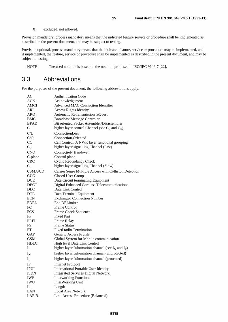
3.4 SymbolsThe symbols defined in this subclause are applied for procedures, features, and services in the present document if notexplicitly otherwise stated. The interpretation of status columns in all tables is as follows:
M for mandatory to support (provision mandatory, process mandatory);
O for optional to support (provision optional, process mandatory);
O.x option comprising number of items;
I for out-of-scope (provision optional, process optional) not subject for testing;
C for conditional to support (process mandatory);
N/A for not-applicable (in the given context the specification makes it impossible to use this capability);
ETSI
Final draft ETSI EN 301 649 V0.5.1 (1999-11)15
X excluded, not allowed.
Provision mandatory, process mandatory means that the indicated feature service or procedure shall be implemented asdescribed in the present document, and may be subject to testing.
Provision optional, process mandatory means that the indicated feature, service or procedure may be implemented, andif implemented, the feature, service or procedure shall be implemented as described in the present document, and may besubject to testing.
NOTE: The used notation is based on the notation proposed in ISO/IEC 9646-7 [22].
3.3 AbbreviationsFor the purposes of the present document, the following abbreviations apply:
AC Authentication CodeACK AcknowledgementAMCI Advanced MAC Connection IdentifierARI Access Rights IdentityARQ Automatic Retransmission reQuestBMC Broadcast Message ControlerBPAD Bit oriented Packet Assembler/DisassemblerC higher layer control Channel (see CS and CF)
C/L ConnectionLessC/O Connection OrientedCC Call Control. A NWK layer functional groupingCF higher layer signalling Channel (Fast)
CNO ConnectioN HandoverC-plane Control planeCRC Cyclic Redundancy CheckCS higher layer signalling Channel (Slow)
CSMA/CD Carrier Sense Multiple Access with Collision DetectionCUG Closed User GroupDCE Data Circuit terminating EquipmentDECT Digital Enhanced Cordless TelecommunicationsDLC Data Link ControlDTE Data Terminal EquipmentECN Exchanged Connection NumberEDEL End DELimiterFC Frame ControlFCS Frame Check SequenceFP Fixed PartFREL Frame RelayFS Frame StatusFT Fixed radio TerminationGAP Generic Access ProfileGSM Global System for Mobile communicationHDLC High level Data Link ControlI higher layer Information channel (see IN and IP)
IN higher layer Information channel (unprotected)
IP higher layer Information channel (protected)
IP Internet ProtocolIPUI International Portable User IdentityISDN Integrated Services Digital NetworkIWF Interworking FunctionsIWU InterWorking UnitL LengthLAN Local Area NetworkLAP-B Link Access Procedure (Balanced)
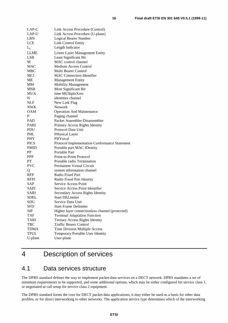
ETSI
Final draft ETSI EN 301 649 V0.5.1 (1999-11)16
LAP-C Link Access Procedure (Control)LAP-U Link Access Procedure (U-plane)LBN Logical Bearer NumberLCE Link Control EntityLI Length Indicator
LLME Lower Layer Management EntityLSB Least Significant BitM MAC control channelMAC Medium Access ControlMBC Multi Bearer ControlMCI MAC Connection IdentifierME Management EntityMM Mobility ManagementMSB Most Significant BitMUX time MUltipleXorsN identities channelNLF New Link FlagNWK NetworkOAM Operation And MaintenanceP Paging channelPAD Packet Assembler-DisassemblerPARI Primary Access Rights IdentityPDU Protocol Data UnitPHL PHysical LayerPHY PHYsicalPICS Protocol Implementation Conformance StatementPMID Portable part MAC IDentityPP Portable PartPPP Point-to-Point ProtocolPT Portable radio TerminationPVC Permanent Virtual CircuitQ system information channelRFP Radio Fixed PartRFPI Radio Fixed Part IdentitySAP Service Access PointSAPI Service Access Point IdentifierSARI Secondary Access Rights IdentitySDEL Start DELimiterSDU Service Data UnitSFD Start Frame DelimiterSIP Higher layer connectionless channel (protected)TAF Terminal Adaptation FunctionTARI Tertiary Access Rights IdentityTBC Traffic Bearer ControlTDMA Time Division Multiple AccessTPUI Temporary Portable User IdentityU-plane User-plane
4 Description of services
4.1 Data services structureThe DPRS standard defines the way to implement packet-data services on a DECT network. DPRS mandates a set ofminimum requirements to be supported, and some additional options, which may be either configured for service class 1,or negotiated at call setup for service class 2 equipment.
The DPRS standard forms the core for DECT packet data applications; it may either be used as a basis for other dataprofiles, or for direct interworking to other networks. The application service type determines which of the interworking
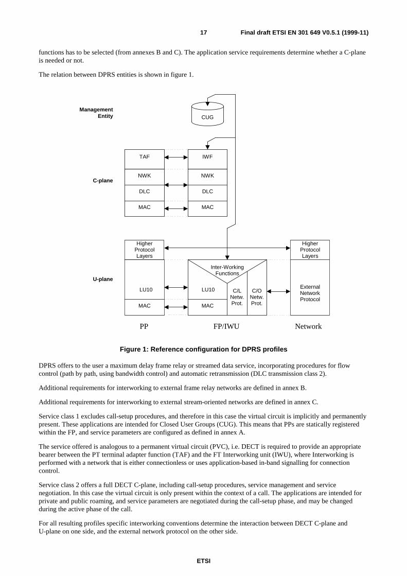
ETSI
Final draft ETSI EN 301 649 V0.5.1 (1999-11)17
functions has to be selected (from annexes B and C). The application service requirements determine whether a C-planeis needed or not.
The relation between DPRS entities is shown in figure 1.
Inter-WorkingFunctions
HigherProtocolLayers
PP FP/IWU Network
LU10 C/LNetw.Prot.
HigherProtocolLayers
IWFTAF
ExternalNetworkProtocol
C/ONetw.Prot.MAC
LU10
MAC
MAC
DLC
NWK
MAC
DLC
NWK
U-plane
CUGManagement
Entity
C-plane
Figure 1: Reference configuration for DPRS profiles
DPRS offers to the user a maximum delay frame relay or streamed data service, incorporating procedures for flowcontrol (path by path, using bandwidth control) and automatic retransmission (DLC transmission class 2).
Additional requirements for interworking to external frame relay networks are defined in annex B.
Additional requirements for interworking to external stream-oriented networks are defined in annex C.
Service class 1 excludes call-setup procedures, and therefore in this case the virtual circuit is implicitly and permanentlypresent. These applications are intended for Closed User Groups (CUG). This means that PPs are statically registeredwithin the FP, and service parameters are configured as defined in annex A.
The service offered is analogous to a permanent virtual circuit (PVC), i.e. DECT is required to provide an appropriatebearer between the PT terminal adapter function (TAF) and the FT Interworking unit (IWU), where Interworking isperformed with a network that is either connectionless or uses application-based in-band signalling for connectioncontrol.
Service class 2 offers a full DECT C-plane, including call-setup procedures, service management and servicenegotiation. In this case the virtual circuit is only present within the context of a call. The applications are intended forprivate and public roaming, and service parameters are negotiated during the call-setup phase, and may be changedduring the active phase of the call.
For all resulting profiles specific interworking conventions determine the interaction between DECT C-plane andU-plane on one side, and the external network protocol on the other side.
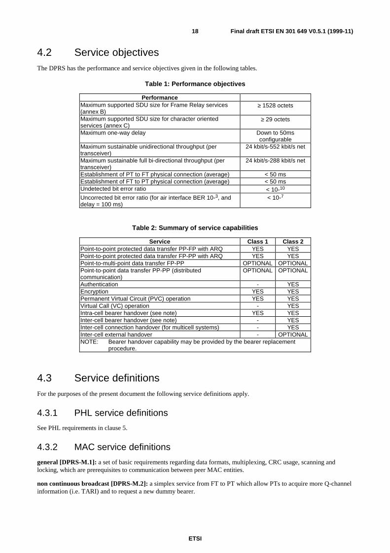
ETSI
Final draft ETSI EN 301 649 V0.5.1 (1999-11)18
4.2 Service objectivesThe DPRS has the performance and service objectives given in the following tables.
Table 1: Performance objectives
PerformanceMaximum supported SDU size for Frame Relay services(annex B)
≥ 1528 octets
Maximum supported SDU size for character orientedservices (annex C)
≥ 29 octets
Maximum one-way delay Down to 50msconfigurable
Maximum sustainable unidirectional throughput (pertransceiver)
24 kbit/s-552 kbit/s net
Maximum sustainable full bi-directional throughput (pertransceiver)
24 kbit/s-288 kbit/s net
Establishment of PT to FT physical connection (average) < 50 msEstablishment of FT to PT physical connection (average) < 50 msUndetected bit error ratio < 10-10
Uncorrected bit error ratio (for air interface BER 10-3, anddelay = 100 ms)
< 10-7
Table 2: Summary of service capabilities
Service Class 1 Class 2Point-to-point protected data transfer PP-FP with ARQ YES YESPoint-to-point protected data transfer FP-PP with ARQ YES YESPoint-to-multi-point data transfer FP-PP OPTIONAL OPTIONALPoint-to-point data transfer PP-PP (distributedcommunication)
OPTIONAL OPTIONAL
Authentication - YESEncryption YES YESPermanent Virtual Circuit (PVC) operation YES YESVirtual Call (VC) operation - YESIntra-cell bearer handover (see note) YES YESInter-cell bearer handover (see note) - YESInter-cell connection handover (for multicell systems) - YESInter-cell external handover - OPTIONALNOTE: Bearer handover capability may be provided by the bearer replacement
procedure.
4.3 Service definitionsFor the purposes of the present document the following service definitions apply.
4.3.1 PHL service definitions
See PHL requirements in clause 5.
4.3.2 MAC service definitions
general [DPRS-M.1]: a set of basic requirements regarding data formats, multiplexing, CRC usage, scanning andlocking, which are prerequisites to communication between peer MAC entities.
non continuous broadcast [DPRS-M.2]: a simplex service from FT to PT which allow PTs to acquire more Q-channelinformation (i.e. TARI) and to request a new dummy bearer.

ETSI
Final draft ETSI EN 301 649 V0.5.1 (1999-11)19
continuous broadcast [DPRS-M.3]: a simplex service from FT to PT whereby the FT maintains at least one bearerwith continuous transmissions. The PT can use the information carried in this bearer to lock to the FT and to obtainknowledge about the FT. (GAP-M.2)
paging broadcast [DPRS-M.4]: a service whereby the identities of specific PTs can be broadcast by the FT. Thisservice is normally used by the FT to request a specific PT to set up a link to the FT. (GAP-M.3)
advanced connection [DPRS-M.5]: a service providing connection between FT and PT consisting of one or moreduplex and zero or more double simplex bearers. Advanced connections have a common connection number, calledExchanged Connection Number (ECN) which is assigned by the ME. Therefore, more than one advanced connectionmay exist between a PT and one FT. The service includes the means for setting-up and releasing the required bearer(s).
Ip_error_detection service [DPRS-M.6]: the IP information is protected by DLC layer retransmission procedures
based on error detection by means of the B-subfield CRC's. The DLC layer takes care of packet lifetime control.
Ip_error_correction service [DPRS-M.7]: the IP information is protected by MAC layer procedures based on a
modulo 2 retransmission scheme. The DLC layer requests the maximum allowed transmission time. Due to theretransmission mechanism, the effective throughput is variable.
U-plane point-to-multipoint service [DPRS-M.8]: a simplex service from FT to PT whereby the FT transfers a singleSDU of U-plane data from one source point to one (or more) destination points. The service uses the SIP logical
channel: the SIP information is protected by MAC layer error detection procedure based on 16 bit CRCS.
CS higher layer signalling [DPRS-M.9]: a low rate connection oriented data service with ARQ using the CS-channel to
transfer higher layer signalling data. (GAP-M.5)
CF higher layer signalling [DPRS-M.10]: a high rate connection oriented data service with ARQ using the CF-channel
to transfer higher layer signalling data.
encryption activation [DPRS-M.11]: a service providing means for enabling the encryption whereby on demand allhigher layer data is transferred across the DECT air interface in an encrypted form. Always initiated by the PT. Aconnection release automatically disables ciphering. (GAP-M.7)
encryption deactivation [DPRS-M.12]: a service providing means for disabling the encryption whereby on demand allhigher layer data is transferred across the DECT air interface in an encrypted form. A connection release automaticallydisables ciphering. (GAP-M.14)
quality control [DPRS-M.13]: provides means for monitoring and controlling the radio link quality. (GAP-M.6)
physical channel selection [DPRS-M.14]: defines the policy for the dynamic selection of a channel, caused by the factthat an old one has to be changed or a new one is needed. Detection of bad quality on the physical channel in use(i.e. due to weak signals or interference), detection of a RFP with a stronger signal than the one of the own RFP,detection of local congestion are all criteria that can be used to select the channel.
Secondary Access Rights Identity (SARI) support [DPRS-M.15]: the ability to support, in addition to the primaryAccess Rights Identity (ARI), secondary ARIs that the FT broadcasts less frequently than PARIs. These may be used toreflect an inter-operators agreement allowing a portable to access more than one operator or services through FT.(GAP-M.13)
Bearer replacement [DPRS-M.16]: bearer quality maintenance by setting up a replacement bearer in the same cluster,with different LBN and without the requirement of maintaining identical data on both bearers. Subsequently the oldbearer is released; for efficiency, the sequence of setup and release may be reversed.
Bearer handover [DPRS-M.17]: bearer quality maintenance by setting up a replacement bearer in the same cluster,with identical LBN and maintaining identical data on both bearers. Subsequently the old bearer is released.
Connection handover [DPRS-M.18]: connection quality maintenance by setting up replacement bearers in the same ora different cluster, each with identical LBN and maintaining identical data bearers with identical LBN. Subsequently theold bearers are released.
Gf-channel [DPRS-M.19]: the Gf-channel is a fast simplex channel that is used to provide control of U-plane entities.For example it is used to carry acknowledgements for asymmetric connections.
ETSI
Final draft ETSI EN 301 649 V0.5.1 (1999-11)20
4.3.3 DLC service definitions
LU10 Enhanced Frame RELay service (EFREL) [DPRS-D.1]: an enhanced frame relay service accessed through theLU10 SAP. The LU10 shall operate on a generic field of user data that shall be transferred into and out of the DLCU-plane as a single SDU. This SDU is assumed to contain one external frame, but the operation of LU10 shall beindependent of the actual contents of the SDU. LU10 shall provide mechanisms that offer reliable transport of thegeneric SDUs, and that preserve the SDU boundaries.
FU10a [DPRS-D.2]: offers a defined fixed length frame structure and buffering functions for transmission of U-planedata to the MAC layer (at the transmit side) or accepts data from the MAC layer (at the receiving side) on demand andwith minimum delay. Frame type FU10a is used for the forward path of unidirectional links.
FU10b [DPRS-D.3]: offers a defined fixed length frame structure and buffering functions for transmission of higherlayer U-plane control data from the DLC to the MAC layer (at the transmit side) or accepts data from the MAC layer(at the receiving side) on demand and with minimum delay. Only be used for symmetrical connections using bi-directional links.
FU10c [DPRS-D.4]: offers a defined fixed length frame structure and buffering functions for transmission of higherlayer U-plane control data from the DLC to the MAC layer (at the transmit side) or accepts data from the MAC layer(at the receiving side) on demand and with minimum delay. Used to carry acknowledgements or negativeacknowledgement for connections. Frame type FU10c is used for the backward control path of unidirectional links: itcontains a list of receive sequence numbers for the forward link.
Data Link Service (LAPC+Lc) class A service [DPRS-D.5]: a single frame acknowledged C-plane data link serviceproviding a data link between one FT and one PT. The higher layer information is segmented (if necessary) andtransmitted in numbered frames. The Lc service, upon which LAPC is defined, provides frame delimiting, transparencyand frame synchronization. (GAP-D.1)
Data Link Service (LAPC+Lc) class U service [DPRS-D.6]: an unacknowledged C-plane data link service providinga data link between one FT and one or more PTs. The higher layer information is segmented (if necessary) andtransmitted in unnumbered frames. The Lc service, upon which LAPC is defined, provides frame delimiting,transparency and frame synchronization, but no error recovery is defined.
Lc Service [DPRS-D.7]: a service providing channel dependant fragmentation, recombination, frame synchronizationand frame delimiting transparency. Fragmentation is obtained by means of dividing a LAPC data unit into more than oneservice data units for delivery to the MAC layer C logical channel, whilst recombination is obtained by means of joiningseveral service units received from the MAC layer C logical channel into a LAPC data unit. Allows the LLME to selectthe logical channel for Lc operation on a frame-by-frame basis.
broadcast Lb service [DPRS-D.8]: a simplex point-to-multipoint transmission using simple fixed length DLC framesproviding a restricted broadcast service in direction FP to PP(s). (GAP-D.3)
intercell voluntary connection handover [DPRS-D.9]: internal handover process provided and initiated by the DLClayer (as a result of a particular policy, implementers dependent, application on link management. E.g. continued poorquality of service from the MAC layer), whereby one set of DLC entities (C-plane and U-plane) can re-route data fromone MAC connection to a second new MAC connection not in the domain of the same cell, while maintaining theservice provided to the NWK layer. (GAP-D.5)
connection modification [DPRS-D.10]: service that allows the DLC to modify a connection with connection type"Unknown".
encryption activation [DPRS-D.11]: transporting the NWK layer encryption request and the cipher key to the MAClayer, thereby enabling the encryption process in the MAC layer. (GAP-D.6)
encryption deactivation [DPRS-D.12]: transporting the NWK layer encryption deactivation request to the MAC layer,thereby disabling the encryption process in the MAC layer. (GAP-D.9)
ETSI
Final draft ETSI EN 301 649 V0.5.1 (1999-11)21
4.3.4 NWK feature definitions
outgoing call [DPRS-N.1]: a call initiated at a DECT PP. (GAP-N.1)
off-hook [DPRS-N.2]: the ability to indicate the action of going off-hook, e.g. to start call set-up or accept a call.(GAP-N.2)
on-hook (FULL Release) [DPRS-N.3]: the ability to indicate the action of going on-hook (e.g. to terminate a call) andfully release the radio resource. (GAP-N.3)
dialled digits (basic) [DPRS-N.4]: the capability to dial digits 0-9, *, #. (GAP-N.4)
register recall [DPRS-N.5]: The ability of the PP to request the invocation of the supplementary service "registerrecall" over the DECT interface and the ability of the FP to transmit the request to the local network. Register recallmeans to seize a register (with dial tone) to permit input of further digits or other action. (GAP-N.5)
go to DTMF signalling (defined tone length) [DPRS-N.6]: go to DTMF signalling with defined tone length.(GAP-N.6)
pause (dialling pause) [DPRS-N.7]: the ability to generate or indicate an dialling pause, e.g. to await further dial tone.(GAP-N.7)
incoming call [DPRS-N.8]: a call received at a DECT PP. (GAP-N.8)
authentication of PP [DPRS-N.9]: the process by which the identity of a DECT PP is checked by the FP. (GAP-N.9)
authentication of user [DPRS-N.10]: the process by which the identity of a user of a DECT PP is checked by the FP.The User Personal Identification (UPI), a personal identification of 0 to 8 digits, manually entered by the user, is usedfor user authentication. (GAP-N.10)
location registration [DPRS-N.11]: a facility whereby a PP can be registered with a FP or a cluster of FPs such thatincoming calls, radio pages or messages may be routed to it. (GAP-N.11)
on-air key allocation [DPRS-N.12]: the capability to transform Authentication Code (AC) into User AuthenticationKey (UAK) using the key allocation procedure. (GAP-N.12)
identification of PP [DPRS-N.13]: the ability for the FP to request and PP to provide specific identificationparameters. (GAP-N.13)
service class indication/assignment [DPRS-N.14]: assignment by the FP to PP of the service class and indication tothe FP by the PP of the contents of its service class. (GAP-N.14)
alerting [DPRS-N.15]: activates or deactivates alerting at the PP using any appropriate indication. (GAP-N.15)
ZAP [DPRS-N.16]: the ability first to assign and then to re-program the account data held in the PP so that access rightsmay be suspended subject to the conditions set by the service provider being met, coupled with the ability to re-programthe account data again to reinstate access rights once these conditions have been met. One ZAP field shall be providedper account field. The PP has the right to authenticate the FP prior to the execution of ZAP suspend. (GAP-N.16)
encryption activation FT initiated [DPRS-N.17]: the activation of the encryption process requested by FT.(GAP-N.17)
subscription registration procedure on-air [DPRS-N.18]: a standardized procedure for loading subscriptionregistration data into a PP in real time over the air-interface. (GAP-N.18)
link control [DPRS-N.19]: the ability to request, accept, maintain and release a data link for the purposes of a NWKlayer procedure. (GAP-N.19)
terminate access rights FT initiated [DPRS-N.20]: the ability of the FP to delete a subscription in the PP.(GAP-N.20)
partial release [DPRS-N.21]: the ability to release an established or in progress Call Control (CC) call whilst retainingthe radio resource for the purpose of accessing further services. (GAP-N.21)
ETSI
Final draft ETSI EN 301 649 V0.5.1 (1999-11)22
go to DTMF (infinite tone length) [DPRS-N.22]: go to DTMF signalling, indicating infinite DTMF tone duration.(GAP-N.22)
go to pulse [DPRS-N.23]: go to pulse (decadic) signalling. (GAP-N.23)
signalling of display characters [DPRS-N.24]: the transmission to the PP of characters to be displayed on the user'sPP display (if provided). (GAP-N.24)
display control characters [DPRS-N.25]: characters sent to the PP to control the user's display in the PP (if provided).Such characters include cursor control, clear screen, home, flash, inverse video etc. (GAP-N.25)
authentication of FT [DPRS-N.26]: the process by which the identity of a FP is checked by the PP. (GAP-N.26)
encryption activation PT initiated [DPRS-N.27]: the activation of the encryption process suggested by PT. The realtime start of ciphering is done in the MAC layer and is always initiated by the PT. (GAP-N.27)
encryption deactivation FT initiated [DPRS-N.28]: the deactivation of the encryption process requested by FT. Thereal time stop of ciphering is done in the MAC layer and is always initiated by the PT. (GAP-N.28)
encryption deactivation PT initiated [DPRS-N.29]: the deactivation of the encryption process suggested by PT. Thereal time stop of ciphering is done in the MAC layer and is always initiated by the PT. (GAP-N.29)
Calling Line Identification Presentation (CLIP) [DPRS-N.30]: the ability to provide the calling party number to thecalled party before accepting the call. (GAP-N.30)
internal call [DPRS-N.31]: a call between 2 users that does not make use of the local network resources. This istypically useful in residential environments. (GAP-N.31)
service call [DPRS-N.32]: a call initiated by a DECT PT for entering of FT related service and adjustment proceduresin a transparent way. After having sent the service call indication, the PT behaves according to the rules of a normal call.(GAP-N.32)
Dynamic parameters allocation [DPRS-N.33]: the ability to assign/negotiate DPRS protocol handling specificparameters.
Service Negotiation [DPRS-N.34]: the ability to negotiate call/service parameters during call set-up.
In call service change [DPRS-N.35]: the ability to modify call/service parameters (e.g. bandwidth, IWU parametersetc.) while the call is maintained.
NWK layer management [DPRS-N.36]: management of NWK layer related data (e.g. identities, location registration,etc.).
Identity assignment [DPRS-N.37]: the ability to assign and store different types of PT related identities.
DECT external handover [DPRS-N.38]: external handover is the process of switching a call in progress from oneFixed Part (FP-1) to another Fixed Part (FP-2). This means the handover occurs between two independent systems,where each system has its own lower layers of protocol and has an independent set of network layer Service AccessPoints (SAPs). To make external handover possible, a common management entity above the two fixed terminations isnecessary. (CAP-N.1)
Message waiting indication [DPRS-N.39]: this feature enables a user to receive an indication of the status of amessage server (e.g. a voice mailbox) to which the user has access to. (CAP-N.4)
Detach [DPRS-N.40]: this feature enables a PT to report to the FT that the PT is not ready to receive calls. (CAP-N.5)
Enhanced location registration [DPRS-N.41]: this feature enables automatic location registration of PT at expectedintervals of time. (CAP-N.6)
On-air modification of user parameters [DPRS-N.42]: this feature enables the FT to modify the active subscriptiondata of the PT. (CAP-N.7)

ETSI
Final draft ETSI EN 301 649 V0.5.1 (1999-11)23
4.3.5 Application service definitions
AC to bitstring mapping [DPRS-A.1]: mapping of the AC into a bitstring. (GAP-A.1)
multiple subscription registration [DPRS-A.2]: the ability of PP to store more than one subscription. (GAP-A.2)
manual entry of the Portable Access Rights Key (PARK) [DPRS-A.3]: the ability of the PP to accept a manual entryof the PARK for ensuring attachment to the right FP in a physical area covered by many providers. (GAP-A.3)
4.3.6 Distributed Communication
Distributed Communication [DPRS-DC.1]: the ability of a DECT terminal to provide means for or assist directcommunication between two terminals, members of a closed local DECT network. Such terminals may be of type HyP,or, of type PP or FP (when additional specific procedures are provided).
5 PHL requirementsThe requirements of EN 300 444 [8], clause 11, shall apply.
6 MAC layer requirementsIn case of mobility class 2, the MAC extended fixed part information message shall be used and, therefore, bit a12 of thefixed part information field shall be set to 1.
6.1 MAC services
Table 3: MAC service support for mobility class 1 and 2
Support statusItem Name of service PT FT
DPRS-M.1 General M MDPRS-M.2 Non continuous broadcast O ODPRS-M.3 Continuous broadcast M MDPRS-M.4 Paging broadcast M MDPRS-M.5 Advanced connections M MDPRS-M.6 Ip_error_detection service M MDPRS-M.7 Ip_error_correction service O ODPRS-M.8 U-plane point-to-multipoint service O ODPRS-M.9 CS higher layer signalling C31 C31
DPRS-M.10 CF higher layer signalling C32 C32
DPRS-M.11 Encryption activation M MDPRS-M.12 Encryption deactivation C33 C33DPRS-M.13 Quality control M MDPRS-M.14 Physical channel selection M MDPRS-M.15 SARI support C31 C32DPRS-M.16 Bearer replacement M MDPRS-M.17 Bearer handover O ODPRS-M.18 Connection handover M ODPRS-M.19 Gf-channel M M
C31: IF (CLASS 1) THEN I ELSE M.C32: IF (CLASS 1) THEN I ELSE O.C33: If DPRS-N.28 or DPRS-N.29 then M else I.
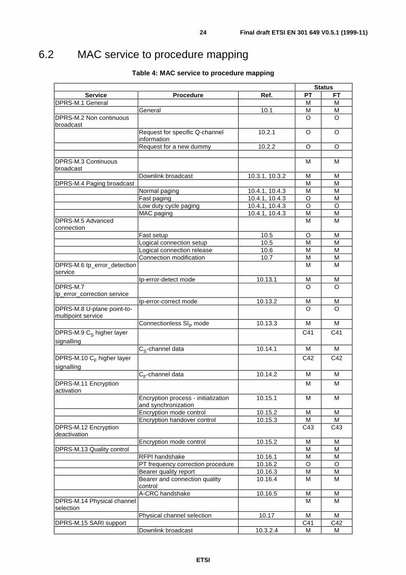
ETSI
Final draft ETSI EN 301 649 V0.5.1 (1999-11)24
6.2 MAC service to procedure mapping
Table 4: MAC service to procedure mapping
StatusService Procedure Ref. PT FT
DPRS-M.1 General M MGeneral 10.1 M M
DPRS-M.2 Non continuousbroadcast
O O
Request for specific Q-channelinformation
10.2.1 O O
Request for a new dummy 10.2.2 O O
DPRS-M.3 Continuousbroadcast
M M
Downlink broadcast 10.3.1, 10.3.2 M MDPRS-M.4 Paging broadcast M M
Normal paging 10.4.1, 10.4.3 M MFast paging 10.4.1, 10.4.3 O MLow duty cycle paging 10.4.1, 10.4.3 O OMAC paging 10.4.1, 10.4.3 M M
DPRS-M.5 Advancedconnection
M M
Fast setup 10.5 O MLogical connection setup 10.5 M MLogical connection release 10.6 M MConnection modification 10.7 M M
DPRS-M.6 Ip_error_detectionservice
M M
Ip-error-detect mode 10.13.1 M MDPRS-M.7Ip_error_correction service
O O
Ip-error-correct mode 10.13.2 M MDPRS-M.8 U-plane point-to-multipoint service
O O
Connectionless SIP mode 10.13.3 M M
DPRS-M.9 CS higher layersignalling
C41 C41
CS-channel data 10.14.1 M M
DPRS-M.10 CF higher layersignalling
C42 C42
CF-channel data 10.14.2 M M
DPRS-M.11 Encryptionactivation
M M
Encryption process - initializationand synchronization
10.15.1 M M
Encryption mode control 10.15.2 M MEncryption handover control 10.15.3 M M
DPRS-M.12 Encryptiondeactivation
C43 C43
Encryption mode control 10.15.2 M MDPRS-M.13 Quality control M M
RFPI handshake 10.16.1 M MPT frequency correction procedure 10.16.2 O OBearer quality report 10.16.3 M MBearer and connection qualitycontrol
10.16.4 M M
A-CRC handshake 10.16.5 M MDPRS-M.14 Physical channelselection
M M
Physical channel selection 10.17 M MDPRS-M.15 SARI support C41 C42
Downlink broadcast 10.3.2.4 M M
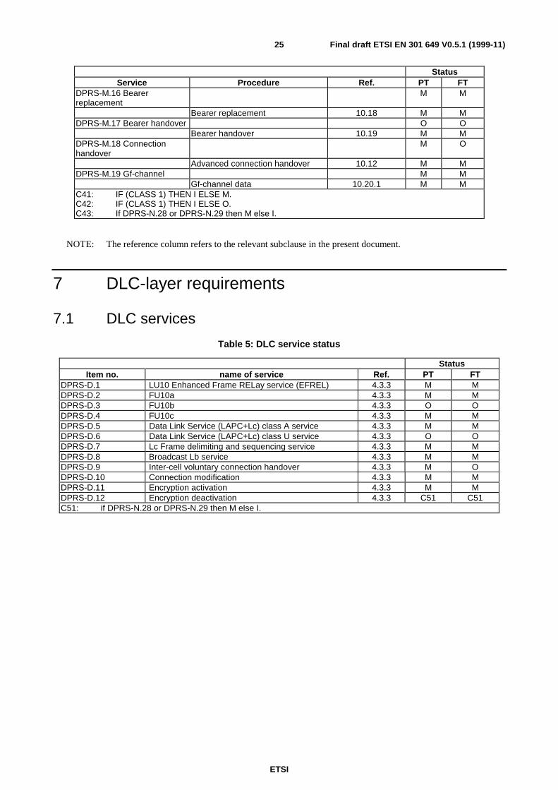
ETSI
Final draft ETSI EN 301 649 V0.5.1 (1999-11)25
StatusService Procedure Ref. PT FT
DPRS-M.16 Bearerreplacement
M M
Bearer replacement 10.18 M MDPRS-M.17 Bearer handover O O
Bearer handover 10.19 M MDPRS-M.18 Connectionhandover
M O
Advanced connection handover 10.12 M MDPRS-M.19 Gf-channel M M
Gf-channel data 10.20.1 M MC41: IF (CLASS 1) THEN I ELSE M.C42: IF (CLASS 1) THEN I ELSE O.C43: If DPRS-N.28 or DPRS-N.29 then M else I.
NOTE: The reference column refers to the relevant subclause in the present document.
7 DLC-layer requirements
7.1 DLC services
Table 5: DLC service status
StatusItem no. name of service Ref. PT FT
DPRS-D.1 LU10 Enhanced Frame RELay service (EFREL) 4.3.3 M MDPRS-D.2 FU10a 4.3.3 M MDPRS-D.3 FU10b 4.3.3 O ODPRS-D.4 FU10c 4.3.3 M MDPRS-D.5 Data Link Service (LAPC+Lc) class A service 4.3.3 M MDPRS-D.6 Data Link Service (LAPC+Lc) class U service 4.3.3 O ODPRS-D.7 Lc Frame delimiting and sequencing service 4.3.3 M MDPRS-D.8 Broadcast Lb service 4.3.3 M MDPRS-D.9 Inter-cell voluntary connection handover 4.3.3 M ODPRS-D.10 Connection modification 4.3.3 M MDPRS-D.11 Encryption activation 4.3.3 M MDPRS-D.12 Encryption deactivation 4.3.3 C51 C51C51: if DPRS-N.28 or DPRS-N.29 then M else I.
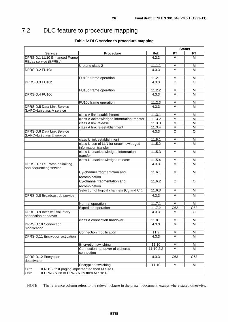
ETSI
Final draft ETSI EN 301 649 V0.5.1 (1999-11)26
7.2 DLC feature to procedure mapping
Table 6: DLC service to procedure mapping
StatusService Procedure Ref. PT FT
DPRS-D.1 LU10 Enhanced FrameRELay service (EFREL)
4.3.3 M M
U-plane class 2 11.1.1 M MDPRS-D.2 FU10a 4.3.3 M M
FU10a frame operation 11.2.1 M MDPRS-D.3 FU10b 4.3.3 O O
FU10b frame operation 11.2.2 M MDPRS-D.4 FU10c 4.3.3 M M
FU10c frame operation 11.2.3 M MDPRS-D.5 Data Link Service(LAPC+Lc) class A service
4.3.3 M M
class A link establishment 11.3.1 M Mclass A acknowledged information transfer 11.3.2 M Mclass A link release 11.3.3 M Mclass A link re-establishment 11.3.4 M M
DPRS-D.6 Data Link Service(LAPC+Lc) class U service
4.3.3 O O
class U link establishment 11.5.1 M Mclass U use of LLN for unacknowledgedinformation transfer
11.5.2 M M
class U unacknowledged informationtransfer
11.5.3 M M
class U unacknowledged release 11.5.4 M MDPRS-D.7 Lc Frame delimitingand sequencing service
4.3.3 M M
CS-channel fragmentation andrecombination
11.6.1 M M
CF-channel fragmentation andrecombination
11.6.2 O O
Selection of logical channels (CS and CF) 11.6.3 M M
DPRS-D.8 Broadcast Lb service 4.3.3 M M
Normal operation 11.7.1 M MExpedited operation 11.7.2 C62 C62
DPRS-D.9 Inter-cell voluntaryconnection handover
4.3.3 M O
class A connection handover 11.8.1 M MDPRS-D.10 Connectionmodification
4.3.3 M M
Connection modification 11.9 M MDPRS-D.11 Encryption activation 4.3.3 M M
Encryption switching 11.10 M MConnection handover of cipheredconnection
11.10.2.2 M M
DPRS-D.12 Encryptiondeactivation
4.3.3 C63 C63
Encryption switching 11.10 M MC62: If N.19 - fast paging implemented then M else I.C63: If DPRS-N.28 or DPRS-N.29 then M else I.
NOTE: The reference column refers to the relevant clause in the present document, except where stated otherwise.

ETSI
Final draft ETSI EN 301 649 V0.5.1 (1999-11)27
8 NWK layer requirementsThe NWK layer provisions shall include the following entities:
• Call Control (CC);
• Mobility Management (MM);
• Link Control Entity (LCE);
• Connectionless Message Service (CLMS).
Only mobility class 2 equipment requires a NWK layer. For mobility class 1 equipment configuration parameters shallbe according to annex A of the present document.
All NWK layer procedures, unless explicitly stated shall be as defined in GAP-EN 300 444 [8], or when relevant, asdefined in CAP-EN 300 824 [9].

ETSI
Final draft ETSI EN 301 649 V0.5.1 (1999-11)28
8.1 NWK features
Table 7: NWK features status
Feature supportedFeatures Status
Item no. Name of feature Ref PT FTDPRS-N.1 Outgoing call 4.3.4 O ODPRS-N.2 Off hook 4.3.4 M MDPRS-N.3 On hook (full release) 4.3.4 M MDPRS-N.4 Dialled digits (basic) 4.3.4 O ODPRS-N.5 Register recall 4.3.4 O ODPRS-N.6 Go to DTMF signalling (defined tone length) 4.3.4 O ODPRS-N.7 Pause (dialling pause) 4.3.4 O ODPRS-N.8 Incoming call 4.3.4 O ODPRS-N.9 Authentication of PP 4.3.4 M M
DPRS-N.10 Authentication of user 4.3.4 O ODPRS-N.11 Location registration 4.3.4 M ODPRS-N.12 On air key allocation 4.3.4 M ODPRS-N.13 Identification of PP 4.3.4 O ODPRS-N.14 Service class indication/assignment 4.3.4 O ODPRS-N.15 Alerting 4.3.4 O ODPRS-N.16 ZAP 4.3.4 O ODPRS-N.17 Encryption activation FT initiated 4.3.4 M MDPRS-N.18 Subscription registration procedure on-air 4.3.4 M MDPRS-N.19 Link control 4.3.4 M MDPRS-N.20 Terminate access rights FT initiated 4.3.4 M ODPRS-N.21 Partial release 4.3.4 O ODPRS-N.22 Go to DTMF (infinite tone length) 4.3.4 O ODPRS-N.23 Go to Pulse 4.3.4 O ODPRS-N.24 Signalling of display characters 4.3.4 O ODPRS-N.25 Display control characters 4.3.4 O ODPRS-N.26 Authentication of FT 4.3.4 O ODPRS-N.27 Encryption activation PT initiated 4.3.4 O ODPRS-N.28 Encryption deactivation FT initiated 4.3.4 O ODPRS-N.29 Encryption deactivation PT initiated 4.3.4 O ODPRS-N.30 Calling Line Identification Presentation (CLIP) 4.3.4 O ODPRS-N.31 Internal call 4.3.4 O ODPRS-N.32 Service call 4.3.4 O ODPRS-N.33 Dynamic parameters allocation 4.3.4 M MDPRS-N.34 Service Negotiation 4.3.4 M MDPRS-N.35 In call service change 4.3.4 O ODPRS-N.36 NWK layer management 4.3.4 M MDPRS-N.37 Identity assignment 4.3.4 O ODPRS-N.38 DECT External handover 5.1 [9] O ODPRS-N.39 Message Waiting Indication 5.1 [9] O ODPRS-N.40 Detach 5.1 [9] O ODPRS-N.41 Periodic location registration 5.1 [9] O ODPRS-N.42 On-air modification of user parameters 5.1 [9] O O
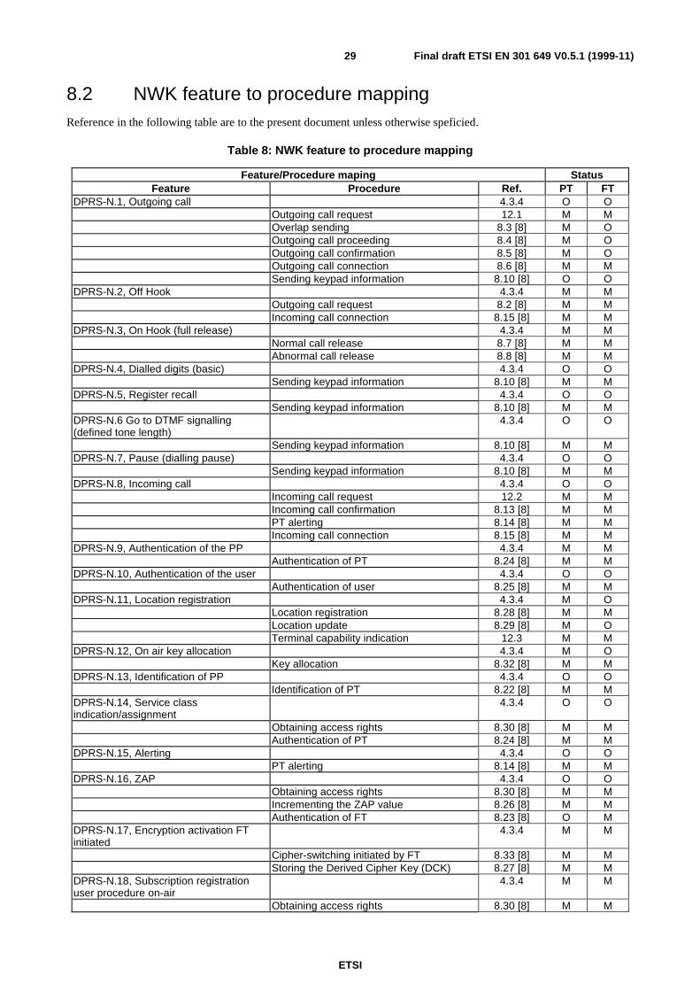
ETSI
Final draft ETSI EN 301 649 V0.5.1 (1999-11)29
8.2 NWK feature to procedure mappingReference in the following table are to the present document unless otherwise speficied.
Table 8: NWK feature to procedure mapping
Feature/Procedure maping StatusFeature Procedure Ref. PT FT
DPRS-N.1, Outgoing call 4.3.4 O OOutgoing call request 12.1 M MOverlap sending 8.3 [8] M OOutgoing call proceeding 8.4 [8] M OOutgoing call confirmation 8.5 [8] M OOutgoing call connection 8.6 [8] M MSending keypad information 8.10 [8] O O
DPRS-N.2, Off Hook 4.3.4 M MOutgoing call request 8.2 [8] M MIncoming call connection 8.15 [8] M M
DPRS-N.3, On Hook (full release) 4.3.4 M MNormal call release 8.7 [8] M MAbnormal call release 8.8 [8] M M
DPRS-N.4, Dialled digits (basic) 4.3.4 O OSending keypad information 8.10 [8] M M
DPRS-N.5, Register recall 4.3.4 O OSending keypad information 8.10 [8] M M
DPRS-N.6 Go to DTMF signalling(defined tone length)
4.3.4 O O
Sending keypad information 8.10 [8] M MDPRS-N.7, Pause (dialling pause) 4.3.4 O O
Sending keypad information 8.10 [8] M MDPRS-N.8, Incoming call 4.3.4 O O
Incoming call request 12.2 M MIncoming call confirmation 8.13 [8] M MPT alerting 8.14 [8] M MIncoming call connection 8.15 [8] M M
DPRS-N.9, Authentication of the PP 4.3.4 M MAuthentication of PT 8.24 [8] M M
DPRS-N.10, Authentication of the user 4.3.4 O OAuthentication of user 8.25 [8] M M
DPRS-N.11, Location registration 4.3.4 M OLocation registration 8.28 [8] M MLocation update 8.29 [8] M OTerminal capability indication 12.3 M M
DPRS-N.12, On air key allocation 4.3.4 M OKey allocation 8.32 [8] M M
DPRS-N.13, Identification of PP 4.3.4 O OIdentification of PT 8.22 [8] M M
DPRS-N.14, Service classindication/assignment
4.3.4 O O
Obtaining access rights 8.30 [8] M MAuthentication of PT 8.24 [8] M M
DPRS-N.15, Alerting 4.3.4 O OPT alerting 8.14 [8] M M
DPRS-N.16, ZAP 4.3.4 O OObtaining access rights 8.30 [8] M MIncrementing the ZAP value 8.26 [8] M MAuthentication of FT 8.23 [8] O M
DPRS-N.17, Encryption activation FTinitiated
4.3.4 M M
Cipher-switching initiated by FT 8.33 [8] M MStoring the Derived Cipher Key (DCK) 8.27 [8] M M
DPRS-N.18, Subscription registrationuser procedure on-air
4.3.4 M M
Obtaining access rights 8.30 [8] M M
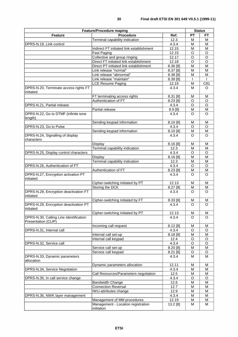
ETSI
Final draft ETSI EN 301 649 V0.5.1 (1999-11)30
Feature/Procedure maping StatusFeature Procedure Ref. PT FT
Terminal capability indication 12.3 M MDPRS-N.19, Link control 4.3.4 M M
Indirect FT initiated link establishment 12.15 M MFast Paging 12.15 O OCollective and group ringing 12.17 O ODirect FT initiated link establishment 12.18 O ODirect PT initiated link establishment 8.36 [8] M MLink release "normal" 8.37 [8] M MLink release "abnormal" 8.38 [8] M MLink release "maintain" 8.39 [8] I ILCE Resume Paging 12.19 M C81
DPRS-N.20, Terminate access rights FTinitiated
4.3.4 M O
FT terminating access rights 8.31 [8] M MAuthentication of FT 8.23 [8] O O
DPRS-N.21, Partial release 4.3.4 O OPartial release 8.9 [8] M M
DPRS-N.22, Go to DTMF (infinite tonelength)
4.3.4 O O
Sending keypad information 8.10 [8] M MDPRS-N.23, Go to Pulse 4.3.4 O O
Sending keypad information 8.10 [8] M MDPRS-N.24, Signalling of displaycharacters
4.3.4 O O
Display 8.16 [8] M MTerminal capability indication 12.3 M M
DPRS-N.25, Display control characters 4.3.4 O ODisplay 8.16 [8] M MTerminal capability indication 12.3 M M
DPRS-N.26, Authentication of FT 4.3.4 O OAuthentication of FT 8.23 [8] M M
DPRS-N.27, Encryption activation PTinitiated
4.3.4 O O
Cipher-switching initiated by PT 12.13 M MStoring the DCK 8.27 [8] M M
DPRS-N.28, Encryption deactivation FTinitiated
4.3.4 O O
Cipher-switching initiated by FT 8.33 [8] M MDPRS-N.29, Encryption deactivation PTinitiated
4.3.4 O O
Cipher-switching initiated by PT 12.13 M MDPRS-N.30, Calling Line IdentificationPresentation (CLIP)
4.3.4 O O
Incoming call request 8.12 [8] M MDPRS-N.31, Internal call 4.3.4 O O
Internal call set-up 8.18 [8] M MInternal call keypad 12.4 O O
DPRS-N.32, Service call 4.3.4 O OService call set-up 8.20 [8] M MService call keypad 8.21 [8] O O
DPRS-N.33, Dynamic parametersallocation
4.3.4 M M
Dynamic parameters allocation 12.11 M MDPRS-N.34, Service Negotiation 4.3.4 M M
Call Resources/Parameters negotiation 12.5 M MDPRS-N.35, In call service change 4.3.4 O O
Bandwidth Change 12.6 M MConnection Reversal 12.7 M MIWU-attributes change 12.9 M M
DPRS-N.36, NWK layer management 4.3.4 M MManagement of MM procedures 12.19 M MManagement - Location registrationinitiation
13.2 [8] M M
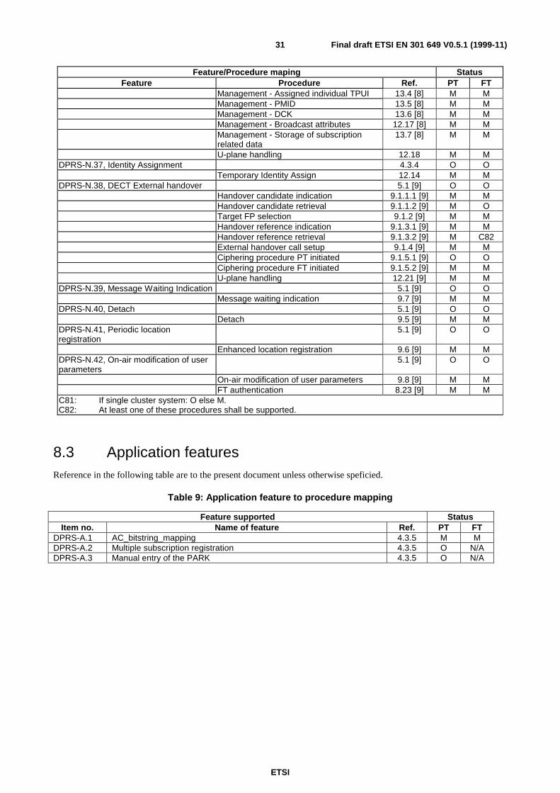
ETSI
Final draft ETSI EN 301 649 V0.5.1 (1999-11)31
Feature/Procedure maping StatusFeature Procedure Ref. PT FT
Management - Assigned individual TPUI 13.4 [8] M MManagement - PMID 13.5 [8] M MManagement - DCK 13.6 [8] M MManagement - Broadcast attributes 12.17 [8] M MManagement - Storage of subscriptionrelated data
13.7 [8] M M
U-plane handling 12.18 M MDPRS-N.37, Identity Assignment 4.3.4 O O
Temporary Identity Assign 12.14 M MDPRS-N.38, DECT External handover 5.1 [9] O O
Handover candidate indication 9.1.1.1 [9] M MHandover candidate retrieval 9.1.1.2 [9] M OTarget FP selection 9.1.2 [9] M MHandover reference indication 9.1.3.1 [9] M MHandover reference retrieval 9.1.3.2 [9] M C82External handover call setup 9.1.4 [9] M MCiphering procedure PT initiated 9.1.5.1 [9] O OCiphering procedure FT initiated 9.1.5.2 [9] M MU-plane handling 12.21 [9] M M
DPRS-N.39, Message Waiting Indication 5.1 [9] O OMessage waiting indication 9.7 [9] M M
DPRS-N.40, Detach 5.1 [9] O ODetach 9.5 [9] M M
DPRS-N.41, Periodic locationregistration
5.1 [9] O O
Enhanced location registration 9.6 [9] M MDPRS-N.42, On-air modification of userparameters
5.1 [9] O O
On-air modification of user parameters 9.8 [9] M MFT authentication 8.23 [9] M M
C81: If single cluster system: O else M.C82: At least one of these procedures shall be supported.
8.3 Application featuresReference in the following table are to the present document unless otherwise speficied.
Table 9: Application feature to procedure mapping
Feature supported StatusItem no. Name of feature Ref. PT FT
DPRS-A.1 AC_bitstring_mapping 4.3.5 M MDPRS-A.2 Multiple subscription registration 4.3.5 O N/ADPRS-A.3 Manual entry of the PARK 4.3.5 O N/A
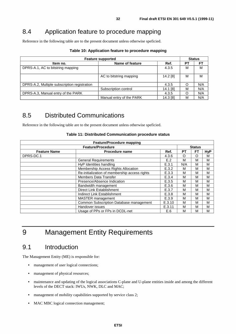
ETSI
Final draft ETSI EN 301 649 V0.5.1 (1999-11)32
8.4 Application feature to procedure mappingReference in the following table are to the present document unless otherwise speficied.
Table 10: Application feature to procedure mapping
Feature supported StatusItem no. Name of feature Ref. PT FT
DPRS-A.1, AC to bitstring mapping 4.3.5 M M
AC to bitstring mapping 14.2 [8] M M
DPRS-A.2, Multiple subscription registration 4.3.5 O N/ASubscription control 14.1 [8] M N/A
DPRS-A.3, Manual entry of the PARK 4.3.5 O N/AManual entry of the PARK 14.3 [8] M N/A
8.5 Distributed CommunicationsReference in the following table are to the present document unless otherwise speficied.
Table 11: Distributed Communication procedure status
Feature/Procedure mappingFeature/Procedure Status
Feature Name Procedure name Ref. PT FT HyPDPRS-DC.1 4.3.6 O O M
General Requirements E.2 M M MHyP Identities handling E.3.1 N/A M MMembership Access Rights Allocation E.3.2 M M MRe-initialization of membership access rights E.3.3 M M MMembers Data Transfer E.3.4 M M MPresence/Absence Indication E.3.5 M M MBandwidth management E.3.6 M M MDirect Link Establishment E.3.7 M M MIndirect Link Establishment E.3.8 M M MMASTER management E.3.9 M M MCommon Subscription Database management E.3.10 M M MHandover issues E.3.11 M M MUsage of PPs or FPs in DCDL-net E.6 M M M
9 Management Entity Requirements
9.1 IntroductionThe Management Entity (ME) is responsible for:
• management of user logical connections;
• management of physical resources;
• maintenance and updating of the logical associations C-plane and U-plane entities inside and among the differentlevels of the DECT stack: IWUs, NWK, DLC and MAC;
• management of mobility capabilities supported by service class 2;
• MAC MBC logical connection management;
ETSI
Final draft ETSI EN 301 649 V0.5.1 (1999-11)33
• MAC TBC and physical connection management;
• DLC U-plane management;
• DLC C-plane management;
• connection handover management (optional).
9.2 Description of the DPRS operation principles
9.2.1 General
In DPRS, the management of the "physical connections" is always under control of the Management Entity (ME). TheME decides in real time the activation, release, or change of bandwidth of the physical connection, based on theexistence of U-plane data or C-plane messages to be transmitted, and according to the requirements described in thissubclause. The higher layer entities are responsible for the presence or absence of the valid data at the MAC serviceboundaries upon which such lower layer resource management is based.
9.2.2 Service class 1
Service class 1 is a simplified version of DPRS that does not incorporate C-plane. Class 1 is intended for small privateapplications with restricted mobility and control features. Because of back-compatibility reasons, class 1 uses an specificad-hoc solution with some differences with class 2 equipment.
In service class 1, the "physical connection", the MBC instance, and the DLC link, are permanently associated. Theactivation and release of the physical resources are done by set-up and release of the DLC "link". All requirementsprovided in this subclause are valid, taken into account that the activation or release of a "physical connection" haveassociated the activation or release of the MBC and DLC layers.
Service class 1 provides an user service that is equivalent to a Permanent Virtual Circuit (PVC).
9.2.3 Service class 2
Service class 2 provides addationally the capabilities of the DECT C-plane. In service class 2, any NWK layer service ispermanently mapped to a DLC layer "link" and to a MBC logical instance called "logical connection". All these entitiesexist during the length of an user connection. User connections could be "Virtual calls" (VC) or "Permanent VirtualCircuits" (PVC).
The allocation of physical resources to the "logical connection" is performed in real time by the Management Entity,based on the existence of U-plane data or C-plane messages to be transmitted, and according to the requirementsdescribed in this subclause. The set of bearers and TBC's temporally allocated to a "logical connection" is the "physicalconnection".
A "logical connection" is in active state if it has associated a "physical connection" and in suspended state otherwise.

ETSI
Final draft ETSI EN 301 649 V0.5.1 (1999-11)34
9.3 Resource and physical connection managementThis section describes when a "Physical Connection" should be set up or released, and which procedures should be used.
9.3.1 Requirements applicable to the Fixed Part (FP)
9.3.1.1 Conditions for resumption and management procedures
9.3.1.1.1 General
The FP may resume a Physical Connection, if any of the following conditions meet:
• there are user plane data to be transmitted downstream;
• there are high layer C-plane data to be transmitted downstream (applicable only to service class 2);
• there are MAC control messages to be transmitted downstream.
NOTE: The activation of the Physical Connection as consequence of the handshake procedure is considered aspart of condition 3 (see subclause 9.4.2.5).
9.3.1.1.2 ME procedures for FT initiated connection resumption.
For equipment of both mobility class 1 and mobility class 2, MAC connection establishment from the FP to the PP goesas follows.
The FP shall try to establish the Physical Connection using the FT initiated set-up procedure (fast set-up) (seesubclause 10.10.1.2) if the PP supports fast set-up and is supposed to be in idle-locked state with set-up detection.
• The PP will be supposed to be in idle-locked state with set-up detection if the time elapsed since the PhysicalConnection was released by last time is lower than timer T909.
The fast set-up procedure should result in at least one set-up attempt. If the PP is supposed not to be in idle-locked statewith set-up detection, then the fast set-up is not required.
If Fast set-up procedure has failed or has not been used, then the FP may try to establish the Physical Connection usingMAC-resume paging (see subclause 10.4), if the PP is known to support MAC-resume paging.
In this case, the FP shall use Fast MAC-resume paging (see subclause 10.4), if the PP is known to support fast paging,and use normal MAC-resume paging (see subclause 10.4) otherwise.
• The ME may freely choose the number of MAC-paging attempts.
NOTE: MAC paging is not required if the FP has done a Fast Setup attempt and Fast Setup is supported by thePP.
If the previous set-up procedures have failed, the FP shall try to establish the Physical Connection using LCE-resumepaging (see subclause 12.16). The FP shall use fast LCE-resume paging, if the PP is known to support fast paging,otherwise it shall use normal paging. The fast paging should result in at least one paging attempt.
If the fast paging fails or if the PP does not support fast paging then the FP tries to establish a Physical Connection withnormal LCE-resume paging.
In case of no response from the PT, the FT may repeat the paging attempt according to implementation specificalgorithms. Process may continue until violation of the handshake (stay alive) procedure (subclause 9.4.2.5), when theconnection shall be released.
ETSI
Final draft ETSI EN 301 649 V0.5.1 (1999-11)35
Class 1 systems
For class 1 systems, the paging shall be initiated by the ME, by issuing a MAC_PAGE-req primitive. The SDU passedwith the primitive shall be such that the contents of the paging message is as defined in EN 300 175-5 [5],subclause 8.2.1, short format message, using default TPUI, with the following exception:
• the LCE header field shall have the value 111 (Ip-error-correct), or 110 (Ip-error-detect).
Receipt of a paging message with a mobility class 1 TPUI indicates that the paging message should be handled bythe ME. Upon receipt of a MAC-PAGE-ind primitive with the TPUI of the PP as parameter, the ME shall issue aMAC_CON-req primitive.
Class 2 Systems: MAC-resume paging
The MAC resume paging shall be done according to subclause 10.4.
Class 2 Systems: LCE-resume paging
The LCE resume paging shall be done according to the procedure described in subclause 12.16.
9.3.1.2 Connection Suspension conditions
9.3.1.2.1 General
The ME of the FP may request a suspension of the connection at any time according to implementation specificalgorithms.
In addition to that, the FP shall request a suspension of the connection in the following cases:
• in case of no user-data or C-plane activity;
• by violation of the minimum number of bearers (MAC Bandwidth command);
• by loss of all received bearers.
The PP is allowed to reject an FP initiated suspension only if the minimum number of bearers negotiated at NWK layeris unequal to zero, and the PP has C-plane or U-plane data ready to be send upstream. In any case, the FP is allowed toforce the PP down to the minimum number of bearers, negotiated by the NWK layer.
9.3.1.2.2 Connection suspension due to no data activity
The ME of the FP shall request a suspension of the connection if no new PDU or C-plane message has been transmittedor received during a consecutive period of T903.
NOTE: Timer T903 is set by the FP (see annex A).
9.3.1.2.3 Connection suspension due to violation of the minimum number of bearers (MACBandwidth command)
The FP shall suspend the connection if the MAC layer is unable to set the "minimum number of bearers" for any of thedirections of the connection, and this situation exists for more time than T906. See subclause 10.7.3 for the suspendprocedure.
NOTE: See annex A for definition and value of T906.
9.3.1.2.4 Connection suspension by loss of all received bearers
The FP will suspend the connection if all received bearers of the connection are lost, and this situation exists for moretime than T908.
NOTE: See annex A for definition and value of T908.
ETSI
Final draft ETSI EN 301 649 V0.5.1 (1999-11)36
9.3.1.3 Activation of Fast Scan mode after Connection suspension
After the suspension of the connection, if the PP supports fast set-up, and parameter T909 (annex A) (class 2 devices) isdifferent from zero, the PP shall pass to Idle-locked state with set-up detection (fast scan mode), as defined inEN 300 175-3 [3], subclause 11.3.3.2.
The PP shall remain in this state for at least the time specified in the parameter T909 During this time, the PP shallaccept FT initiated bearer set-up using the procedure defined in (see to clause 10). After this time the PP may pass tonormal Idle-locked state with page detection (EN 300 175-3 [3], subclause 11.3.3.1).
For service class 1 equipment the value of T909 is stored in the PP configuration table (see clause A.2).
For service class 2 equipment, T909 is variable parameter that can be negotiated between FT and PT by means of the<<SETUP-CAPABILITY>> NWK layer information element (see subclause A.1.3.2).
PTs that do not support fast set-up can ignore this information element.
9.3.1.4 Conditions for Bandwidth modification
9.3.1.4.1 General
The ME of the FP could decide a change in the bandwidth of a connection at any time according to implementationspecific algorithms. The FP will use the Bandwidth modification procedure described in subclause 10.7).
The PP shall mandatorely accept any change of Bandwidth instanced by the FP if the requested bandwidth is within themaximum and minimum values negotiated at NWK layer.
9.3.2 Requirements applicable to the Portable Part (PP)
9.3.2.1 Conditions for connection resumption
The Connection will be resumed by the PP if and only if any of the following conditions meet:
• the PP has U-plane date ready to be sent upstream;
• the PP has C-plane data ready to be sent upstream;
• the PP has MAC control messages to be transmitted upstream;
• the PP initiated this procedure with the result of being refused by the FP, as described in subclause 9.3.2.1.5, anda time equal to WtB ("Waiting time B"), defined in annex A, has elapsed.
NOTE: The resumption of the Physical Connection as consequence of the handshake procedure is considered aspart of condition 3.
If the connection was previously suspended by the FP, (subclause 9.3.1.2.1), the PP shall not request a connectionresume during an interval equal to WtB ("Waiting time B") as defined in annex A.
9.3.2.1.1 Procedure for PT initiated Connection resumption.
The sequence of procedures for the resumption of a connection shall consist on PT initiated pilot bearer set-up(subclause 10.10) followed by connection modification (subclause 10.7).
9.3.2.1.2 "RFP-busy-for-data" flag
The PT shall not initiate the PT initiated connection resumption procedure if the RFP has activated the RFP-busy-for-data flag in RFP status (EN 300 175-3 [3], subclause 7.2.4.3.9).

ETSI
Final draft ETSI EN 301 649 V0.5.1 (1999-11)37
9.3.2.1.3 Waiting time for collision avoidance after deactivation of "RFP-busy-for-data" flag
If the RFP had activated the RFP-busy-for-data flag in RFP status (EN 300 175-3 [3], 7.2.4.3.9), after the deactivationof this flag, the PT shall wait a random interval WtA (see subclause A.1.2.1) before initiating any bearer set-upprocedure, to prevent access collisions. In case of access collision during the following PT initiated set-up procedure(subclause 10.10), the PT shall wait a random interval WtA before repeating the access request attempt. In case ofsuccessive collisions, formula will be applied with successive increment in the spreading range.
9.3.2.1.4 Bandwidth after resumption
As consequence of the procedure, the FP will inform the PP about the number of bearers (bandwidth) to be used. Thisvalue shall be within the range negotiated by the network layer. The PP will use always the bandwidth mandated by theFP.
9.3.2.1.5 Resumption rejection by the FP
If as consequence of the set-up procedure, the FP rejects the access attempt with the message Bandwidh = zero, the PPwill do the following actions:
• PT shall immediately release all bearers;
• PT shall wait the waiting time WtB (see subclause A.1.2.2) and shall repeat the pilot bearer set-up procedure(subclause 10.10).
In case of repetitive failures the waiting time WtB shall be increased to obtain congestion avoidance, according to theformulae given in annex A.
9.3.2.2 Conditions for Connection Suspension
9.3.2.2.1 General
The ME of the PP may request a suspension of the Connection at any time according to implementation specificalgorithms.
In addition to that, the PP shall initiate a suspension of the Connection in the following cases:
• in case of no user-data or C-plane activity;
• by violation of the minimum number of bearers (MAC Bandwidth command);
• by loss of all received bearers.
The PP is allowed to reject an FP initiated suspension only if the minimum number of bearers negotiated at NWK layeris unequal to zero, and the PP has C-plane or U-plane data ready to be send upstream. In any case, the FP is allowed toforce the PP down to the minimum number of bearers, negotiated by the NWK layer.
9.3.2.2.2 Connection suspension due to no data activity
The ME of the PP shall request a suspension of the connection if no new PDU or C-plane message has been transmittedor received during a consecutive period of T903.
NOTE: Timer T903 is broadcasted by the FP (see annex A).
9.3.2.2.3 Connection suspension due to violation of the minimum number of bearers (MACBandwidth command)
The PP shall suspend a Connection if the MAC layer is unable to set the "minimum number of bearers" for any of thedirections of the connection, and this situation exists for more time than T906. See subclause 10.7.3 for suspendprocedure.
NOTE: See annex A for definition and value of T906.
ETSI
Final draft ETSI EN 301 649 V0.5.1 (1999-11)38
9.3.2.2.4 Connection suspension by loss of all received bearers
The PP will suspend a Connection if all received bearers of the connection are lost, and this situation exists for moretime than T908.
NOTE: See annex A for definition and value of T908.
9.3.2.2.5 Activation of fast scan mode after Connection suspension
The same requirements specified in clause are applicable in this case.
9.3.2.3 Conditions for Bandwidth modification
9.3.2.3.1 General
The ME of the PP could request a change in the bandwidth of a connection at any time according to implementationspecific algorithms. The PP will use the Bandwidth modification procedure described in subclause 12.6.
The Bandwidth modification requested by the PP has the nature of suggestion. The FP is free to accept or not theBandwidth modification requested by the PP. The PP will mandatorely accept the Bandwidth indicated by the FP in theanswer to the Bandwidth message if the value is within the maximum and minimum values negotiated at NWK layer.
When as described in subclause 10.7, the PP requests a suspension of the Connection, the FP will decide, taken intoaccount the existence or not of data downstream, whether to suspend the Connection, or to modify the bandwidth(i.e. reverting the direction). Decision is indicated in the values of the bandwidth message sent by the FP.
When a PT has requested a bandwidth modification that involves increasing the number of bearers, and it has beenrefused by the FT, the PT shall not repeat the request of bandwidth extension during an interval WtB (seesubclause A.1.2.2).
NOTE: The PT may request bandwidth modification reducing number of bearers at any time.
9.4 Logical Connection managementThis section describes when the "Logical Connections" should be suspended or released, and which procedures shouldbe used.
9.4.1 Requirements for class 1 devices
In DPRS service class 1, the MBC and the DLC layer instances associated to a single "physical connection" are set upand released together with the "Physical Connection". There are no specific requirements for Logical connectionmanagement.
9.4.2 Requirements for class 2 devices
9.4.2.1 General Description
DPRS service class 2 supports two types of user Connections: Virtual calls (VC) and Permanent Virtual Circuits (PVC).
"Virtual Calls" (VC) are packet-mode user connections that can be set up and released by means of NWK layer C-planeprocedures. A "Virtual Call" is the equivalent in packet-mode to a circuit-mode "Call".
"Permanent Virtual Circuit" (PVC) are packet-mode user connections that are established and cleared by configuration.A "Permanent Virtual Circuit" is the equivalent in packet-mode to a circuit-mode "Leased Line".
In DPRS, service class 2, any user connection has permanently associated a DLC layer "link" and a MBC "logicalconnection".
ETSI
Final draft ETSI EN 301 649 V0.5.1 (1999-11)39
9.4.2.2 Normal procedures of virtual call set-up and release
Virtual Calls are set up always by means of the NWK layer CC-SETUP (subclause 12.5) procedure. Set up of theVirtual Call will cause the creation of a DLC "link" and a MBC "logical connection" associated to the call.
The normal release of VC's is done by means of the NWK layer Call release procedure (see clause 12) TheCC-RELEASE message (see clause 12) shall be exchanged between both peers. The releasing of the virtual callautomatically causes the clearing of the DLC and MBC "logical connection" associated to the call.
9.4.2.3 Abnormal release of Virtual Calls
Virtual Calls may be released by the ME without NWK layer Call-release procedures in case of violation of thehandshake (stay alive) procedure described in next subclause. The abnormal release of a virtual call automaticallycauses the clearing of the DLC and MBC "logical connection" associated to the call.
In the case of PVC's set up by configuration, the connections shall never be released. In case of failure of the handshakeprocedure, a notification will be send to the OAM subsystem in the FP side.
9.4.2.4 Release of Logical Connection
The MAC logical connection is released in the following cases:
• in case of normal release of the Virtual Call (see subclause 9.4.2.2);
• in case of abnormal release of the Virtual Call (see subclause 9.4.2.3);
• as consequence of connection handover procedure (see subclause 11.7).
9.4.2.5 The handshake (stay alive) procedure
To get a handshake control for suspended connections, a connection shall not be in suspended state for more than T910.To meet this rule, the PT is responsible to perform a handshake with the FT at least T910-T200 after entering thesuspend state. In order to avoid connection release caused by a single bearer set-up procedure that failed, PTs shallperform such handshake in shorter time intervals than T910.The PT shall try five handshake attempts within T910. Aftersuccessfull handshake (succesful bearer setup) the Timer T910 and the counter for handshake attempts shall be reset.
To perform a handshake, the PT shall execute a PT initiated pilot bearer set-up procedure (subclause 10.10) followed bya bandwidth modification with a requested value of zero.
NOTE 1: In order to expedite the process, the PT is allowed to send the messages "bearer request" and"bandwidth = 0" in the same frame.
The FP is allowed to initiate a handshake with the PT at any time.
If a MAC connection associated to a Virtual Call has been in suspend state for more than T910, the connection,including the controlling MBC, the associated DLC and the virtual call shall be released.
NOTE 2: As no physical connection is established, this clearing procedure doesn't need any further air interface(bearer release) procedure.
NOTE 3: T200 is the MAC connection set-up timer. Its value can be found in EN 300 175-3 [3], clause A.1.
ETSI
Final draft ETSI EN 301 649 V0.5.1 (1999-11)40
10 MAC layer procedures
10.1 General
10.1.1 Frame and multiframe structure
The FT and PT shall support frame and multiframe structures as defined in EN 300 175-3 [3] subclause 4.2.
10.1.2 Bit mappings
The FT and PT shall support D-MAP D00 and D32, A-MAP, and protected format B-MAP as defined inEN 300 175-3 [3] subclause 6.2.1.
10.1.3 Time multiplexers
The FT and PT shall support T-MUX, E/U-MUX E32 and U32b, and C-MUX as defined in EN 300 175-3 [3]subclause 6.2.2.
10.1.5 Scrambling
The FT and PT shall support scrambling as defined in EN 300 175-3 [3] subclause 6.2.4.
10.1.6 Error control
The FT and PT shall support R-CRC and X-CRC generation as defined in EN 300 175-3 [3] subclause 6.2.5.
10.1.7 A-tail identifications
The FT and PT shall understand all A-field tail identifications (bits a0 to a2) as defined in EN 300 175-3 [3]subclause 7.1.2.
10.1.8 B-field identifications
The FT and PT shall understand all B-field identifications (bits a4 to a6) as defined in EN 300 175-3 [3]subclause 7.1.4.
10.1.9 RFP idle receiver scan sequence
The FT shall support primary scan as defined in EN 300 175-3 [3] subclause 11.8.
10.1.10 PT receiver scan sequence
The PT receive scan sequence, whenever active, shall lead the RFP primary scan by one frame, as defined inEN 300 175-3 [3] subclause 11.9.
10.1.11 PP states and state transitions
The procedure shall be performed as specified in EN 300 175-3 [3] subclause 11.3.3, with the following provisions:
• The PT shall allow fast setup (if supported) for a period of time immediately following the transition fromActive_Locked to Idle_Locked state. The duration of this period is communicated to MAC by ME (seesubclause 9.3.1.3).
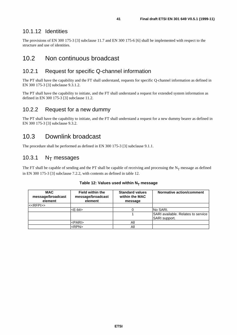
ETSI
Final draft ETSI EN 301 649 V0.5.1 (1999-11)41
10.1.12 Identities
The provisions of EN 300 175-3 [3] subclause 11.7 and EN 300 175-6 [6] shall be implemented with respect to thestructure and use of identities.
10.2 Non continuous broadcast
10.2.1 Request for specific Q-channel information
The PT shall have the capability and the FT shall understand, requests for specific Q-channel information as defined inEN 300 175-3 [3] subclause 9.3.1.2.
The PT shall have the capability to initiate, and the FT shall understand a request for extended system information asdefined in EN 300 175-3 [3] subclause 11.2.
10.2.2 Request for a new dummy
The PT shall have the capability to initiate, and the FT shall understand a request for a new dummy bearer as defined inEN 300 175-3 [3] subclause 9.3.2.
10.3 Downlink broadcastThe procedure shall be performed as defined in EN 300 175-3 [3] subclause 9.1.1.
10.3.1 NT messages
The FT shall be capable of sending and the PT shall be capable of receiving and processing the NT message as defined
in EN 300 175-3 [3] subclause 7.2.2, with contents as defined in table 12.
Table 12: Values used within NT message
MACmessage/broadcast
element
Field within themessage/broadcast
element
Standard valueswithin the MAC
message
Normative action/comment
<<RFPI>><E-bit> 0 No SARI.
1 SARI available. Relates to serviceSARI support.
<PARI> All<RPN> All

ETSI
Final draft ETSI EN 301 649 V0.5.1 (1999-11)42
10.3.2 QT messages
10.3.2.1 QT - static system information
The FT shall be capable of sending and the PT shall be capable of receiving and processing the QT static system
information message as defined in EN 300 175-3 [3] subclause 7.2.3.2, with contents as defined below.
Table 13: Values used within static system info
MAC message Field withinthe message
Standard valueswithin the MAC
message
Normative action/comment
<<Static system info>><QH> 0
<NR> 0, 1 PT shall support all values in order to gain lock.Asymmetric connections are not required to besupported by the PT.
<SN> 0 to 11 PT shall support all values.<SP> 0 PT shall support all values in order to gain lock. Half
slot connections are not required to be supported bythe PT.
<ESC> 0, 1 PT may ignore and assume the value to be 0.<Txs> 0 to 3 PT may ignore and assume the value to be 0.<Ext-car> 0, 1 PT shall support all values in order to keep in
synchronization with the primary scan.<RF-car> 1 to 1 023 The PT shall not use carriers, which are not
supported.<SPR> 0 PT may ignore.<CN> 0 to 9,
10 to 32PT shall support normal values,and extended frequencies. The PT is not required tosupport transmission/reception on the extendedfrequencies.
<SPR> 0 PT may ignore.<PSCN> 0 to 9,
10 to 32PT shall support normal values,PT may be not able to transmit on any of theextended frequencies, however it shall be able tocalculate the exact position of the PSCN based onall indicated to be supported by the FT carriers.
In case the <Ext-car> bit is set to 1, the RFP shall also broadcast the extended RF carrier information message asdefined in EN 300 175-3 [3] subclause 7.2.3.3, where the fields are allowed the following values:
Table 14: Values used within extended RF carrier info
MAC message Field withinthe message
Standard valueswithin the MAC
message
Normative action/comment
<<Extended RF carrierinformation>>
<QH> 2
<RF carriers> A12 – a34: {0, 1} These bits may be set to indicate support forcarriers 10-32
<RF band> All relevant For values see physical layer spec<SPR> 0 PT may ignore<Nr of RFcarriers>
all
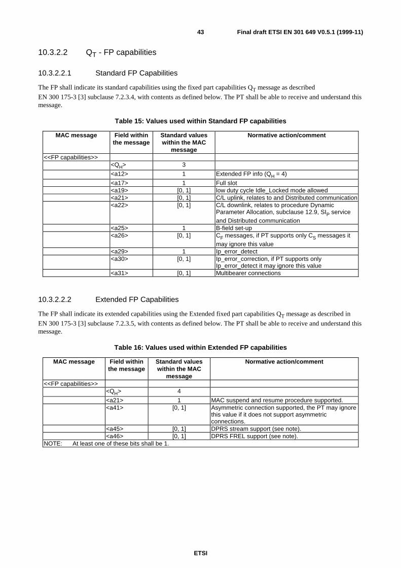
ETSI
Final draft ETSI EN 301 649 V0.5.1 (1999-11)43
10.3.2.2 QT - FP capabilities
10.3.2.2.1 Standard FP Capabilities
The FP shall indicate its standard capabilities using the fixed part capabilities QT message as described
EN 300 175-3 [3] subclause 7.2.3.4, with contents as defined below. The PT shall be able to receive and understand thismessage.
Table 15: Values used within Standard FP capabilities
MAC message Field withinthe message
Standard valueswithin the MAC
message
Normative action/comment
<<FP capabilities>><QH> 3
<a12> 1 Extended FP info (QH = 4)
<a17> 1 Full slot<a19> [0, 1] low duty cycle Idle_Locked mode allowed<a21> [0, 1] C/L uplink, relates to and Distributed communication<a22> [0, 1] C/L downlink, relates to procedure Dynamic
Parameter Allocation, subclause 12.9, SIP serviceand Distributed communication
<a25> 1 B-field set-up<a26> [0, 1] CF messages, if PT supports only CS messages it
may ignore this value<a29> 1 Ip_error_detect<a30> [0, 1] Ip_error_correction, if PT supports only
Ip_error_detect it may ignore this value<a31> [0, 1] Multibearer connections
10.3.2.2.2 Extended FP Capabilities
The FP shall indicate its extended capabilities using the Extended fixed part capabilities QT message as described in
EN 300 175-3 [3] subclause 7.2.3.5, with contents as defined below. The PT shall be able to receive and understand thismessage.
Table 16: Values used within Extended FP capabilities
MAC message Field withinthe message
Standard valueswithin the MAC
message
Normative action/comment
<<FP capabilities>><QH> 4
<a21> 1 MAC suspend and resume procedure supported.<a41> [0, 1] Asymmetric connection supported, the PT may ignore
this value if it does not support asymmetricconnections.
<a45> [0, 1] DPRS stream support (see note).<a46> [0, 1] DPRS FREL support (see note).
NOTE: At least one of these bits shall be 1.
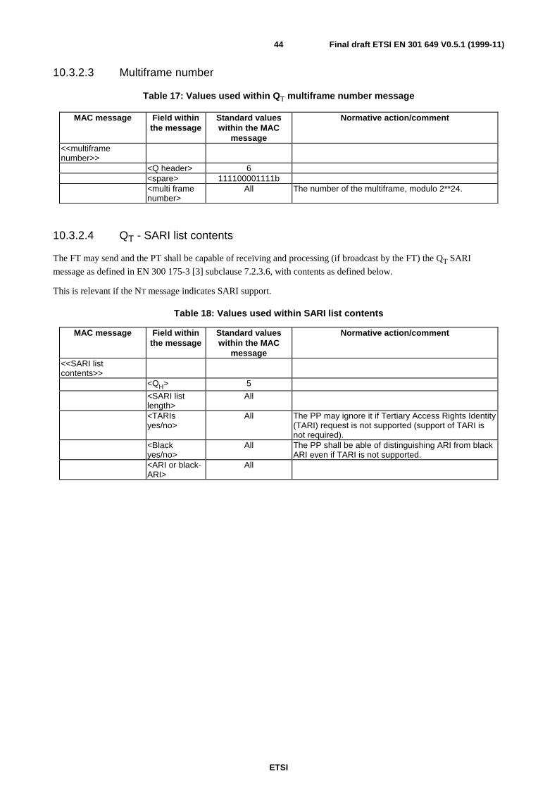
ETSI
Final draft ETSI EN 301 649 V0.5.1 (1999-11)44
10.3.2.3 Multiframe number
Table 17: Values used within QT multiframe number message
MAC message Field withinthe message
Standard valueswithin the MAC
message
Normative action/comment
<<multiframenumber>>
<Q header> 6<spare> 111100001111b<multi framenumber>
All The number of the multiframe, modulo 2**24.
10.3.2.4 QT - SARI list contents
The FT may send and the PT shall be capable of receiving and processing (if broadcast by the FT) the QT SARI
message as defined in EN 300 175-3 [3] subclause 7.2.3.6, with contents as defined below.
This is relevant if the NT message indicates SARI support.
Table 18: Values used within SARI list contents
MAC message Field withinthe message
Standard valueswithin the MAC
message
Normative action/comment
<<SARI listcontents>>
<QH> 5
<SARI listlength>
All
<TARIsyes/no>
All The PP may ignore it if Tertiary Access Rights Identity(TARI) request is not supported (support of TARI isnot required).
<Blackyes/no>
All The PP shall be able of distinguishing ARI from blackARI even if TARI is not supported.
<ARI or black-ARI>
All
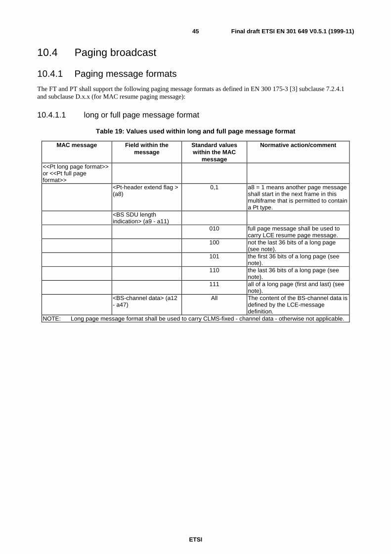
ETSI
Final draft ETSI EN 301 649 V0.5.1 (1999-11)45
10.4 Paging broadcast
10.4.1 Paging message formats
The FT and PT shall support the following paging message formats as defined in EN 300 175-3 [3] subclause 7.2.4.1and subclause D.x.x (for MAC resume paging message):
10.4.1.1 long or full page message format
Table 19: Values used within long and full page message format
MAC message Field within themessage
Standard valueswithin the MAC
message
Normative action/comment
<<Pt long page format>>or <<Pt full pageformat>>
<Pt-header extend flag >(a8)
0,1 a8 = 1 means another page messageshall start in the next frame in thismultiframe that is permitted to containa Pt type.
<BS SDU lengthindication> (a9 - a11)
010 full page message shall be used tocarry LCE resume page message.
100 not the last 36 bits of a long page(see note).
101 the first 36 bits of a long page (seenote).
110 the last 36 bits of a long page (seenote).
111 all of a long page (first and last) (seenote).
<BS-channel data> (a12- a47)
All The content of the BS-channel data isdefined by the LCE-messagedefinition.
NOTE: Long page message format shall be used to carry CLMS-fixed - channel data - otherwise not applicable.
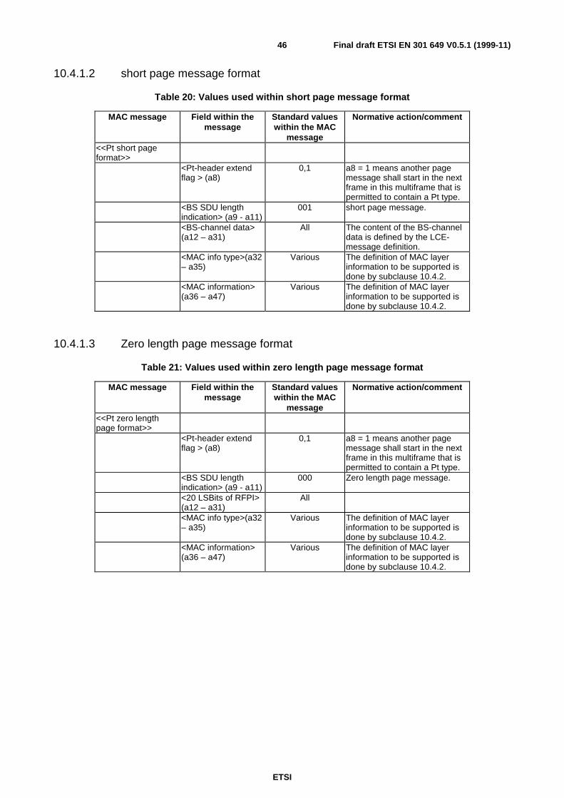
ETSI
Final draft ETSI EN 301 649 V0.5.1 (1999-11)46
10.4.1.2 short page message format
Table 20: Values used within short page message format
MAC message Field within themessage
Standard valueswithin the MAC
message
Normative action/comment
<<Pt short pageformat>>
<Pt-header extendflag > (a8)
0,1 a8 = 1 means another pagemessage shall start in the nextframe in this multiframe that ispermitted to contain a Pt type.
<BS SDU lengthindication> (a9 - a11)
001 short page message.
<BS-channel data>(a12 – a31)
All The content of the BS-channeldata is defined by the LCE-message definition.
<MAC info type>(a32– a35)
Various The definition of MAC layerinformation to be supported isdone by subclause 10.4.2.
<MAC information>(a36 – a47)
Various The definition of MAC layerinformation to be supported isdone by subclause 10.4.2.
10.4.1.3 Zero length page message format
Table 21: Values used within zero length page message format
MAC message Field within themessage
Standard valueswithin the MAC
message
Normative action/comment
<<Pt zero lengthpage format>>
<Pt-header extendflag > (a8)
0,1 a8 = 1 means another pagemessage shall start in the nextframe in this multiframe that ispermitted to contain a Pt type.
<BS SDU lengthindication> (a9 - a11)
000 Zero length page message.
<20 LSBits of RFPI>(a12 – a31)
All
<MAC info type>(a32– a35)
Various The definition of MAC layerinformation to be supported isdone by subclause 10.4.2.
<MAC information>(a36 – a47)
Various The definition of MAC layerinformation to be supported isdone by subclause 10.4.2.

ETSI
Final draft ETSI EN 301 649 V0.5.1 (1999-11)47
10.4.1.4 MAC resume page message format
Table 22: Values used within MAC resume page message format
MAC message Field within themessage2
Standard valueswithin the MAC
message
Normative action/comment
<<Pt MAC resume pageformat>>
<Pt-header extend flag >(a8)
0,1 a8 = 1 means another page messageshall start in the next frame in thismultiframe that is permitted to containa Pt type.
<BS SDU lengthindication> (a9 - a11)
011 MAC resume page.
<PMID>(a12 – a31) All PMID.<ECN> (a32-a35) All Exchanged connection number.(a36 – a47) 1111 1111 1111 Reserved.
10.4.2 MAC layer information in zero and short length paging messages
The following MAC layer information types defined by EN 300 175-3 [3] subclause 7.2.4.3 shall be supported(understood) by a PT:
Table 23: Types of MAC layer paging information to be supported by a PT
a32 a33 a34 a35 MAC information type0 0 0 1 blind slot information0 0 1 0 other bearer0 0 1 1 Recommended other bearer0 1 0 1 dummy or C/L bearer position1 1 0 0 C/L bearer position1 0 0 1 bearer handover information1 0 1 0 RFP-status.
The procedure how to react on RFP-status "RFP-busy-for-data" is definedby subclause 9.3.2.1.2.
10.4.3 FP paging procedure
The procedure shall be performed as defined by EN 300 175-3 [3] subclause 9.1.3.1.
The FP shall support normal paging and fast paging procedure as defined by EN 300 175-3 [3] subclause 9.1.3.1.Additionally FP shall support normal and fast paging for MAC resume page in the same way as for full page messageformat.
The support of low-duty-cycle-mode by page repetition is optional for the FP.
10.4.4 PP paging procedure (Detection of paging message in idle lockedmode)
The procedure shall be performed as defined by EN 300 175-3 [3] subclause 9.1.3.2.
If the PP supports fast paging procedure by usage of the high-duty-cycle-mode it shall announce that to the FP by theusage of the <<setup capabilites>> – IE as defined by subclause 12.11.
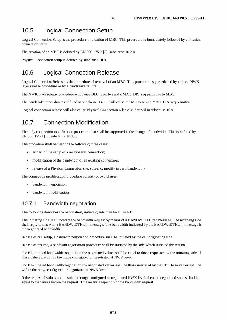
ETSI
Final draft ETSI EN 301 649 V0.5.1 (1999-11)48
10.5 Logical Connection SetupLogical Connection Setup is the procedure of creation of MBC. This procedure is immediately followed by a Physicalconnection setup.
The creation of an MBC is defined by EN 300 175-3 [3], subclause 10.2.4.1.
Physical Connection setup is defined by subclause 10.8.
10.6 Logical Connection ReleaseLogical Connection Release is the procedure of removal of an MBC. This procedure is precededed by either a NWKlayer release procedure or by a handshake failure.
The NWK layer release procedure will cause DLC layer to send a MAC_DIS_req primitive to MBC.
The handshake procedure as defined in subclause 9.4.2.3 will cause the ME to send a MAC_DIS_req primitive.
Logical connection release will also cause Physical Connection release as defined in subclause 10.9.
10.7 Connection ModificationThe only connection modification procedure that shall be supported is the change of bandwidth. This is defined byEN 300 175-3 [3], subclause 10.3.1.
The procedure shall be used in the following three cases:
• as part of the setup of a multibearer connection;
• modification of the bandwidth of an existing connection;
• release of a Physical Connection (i.e. suspend, modify to zero bandwidth).
The connection modification procedure consists of two phases:
• bandwidth negotiation;
• bandwidth modification.
10.7.1 Bandwidth negotiation
The following describes the negotiation, initiating side may be FT or PT.
The initiating side shall indicate the bandwidth request by means of a BANDWIDTH.req message. The receiving sideshall reply to this with a BANDWIDTH.cfm message. The bandwidth indicated by the BANDWIDTH.cfm message isthe negotiated bandwidth.
In case of call setup, a bandwith negotiation procedure shall be initiated by the call originating side.
In case of resume, a bandwith negotiation procedure shall be initiated by the side which initiated the resume.
For FT-initiated bandwidth-negotiation the negotiated values shall be equal to those requested by the initiating side, ifthese values are within the range configured or negotiated at NWK level.
For PT-initiated bandwidth-negotiation the negotiated values shall be those indicated by the FT. These values shall bewithin the range configured or negotiated at NWK level.
If the requested values are outside the range configured or negotiated NWK level, then the negotiated values shall beequal to the values before the request. This means a rejection of the bandwidth request.
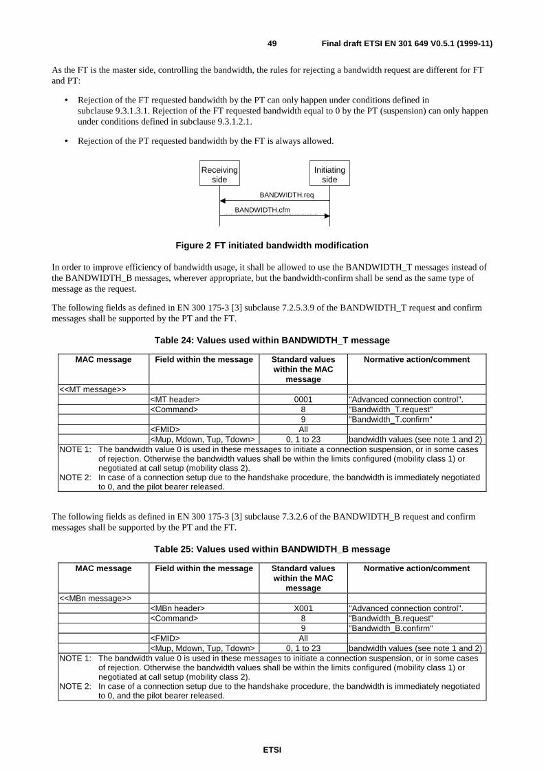
ETSI
Final draft ETSI EN 301 649 V0.5.1 (1999-11)49
As the FT is the master side, controlling the bandwidth, the rules for rejecting a bandwidth request are different for FTand PT:
• Rejection of the FT requested bandwidth by the PT can only happen under conditions defined insubclause 9.3.1.3.1. Rejection of the FT requested bandwidth equal to 0 by the PT (suspension) can only happenunder conditions defined in subclause 9.3.1.2.1.
• Rejection of the PT requested bandwidth by the FT is always allowed.
BANDWIDTH.cfm
BANDWIDTH.req
Initiatingside
Receivingside
Figure 2 FT initiated bandwidth modification
In order to improve efficiency of bandwidth usage, it shall be allowed to use the BANDWIDTH_T messages instead ofthe BANDWIDTH_B messages, wherever appropriate, but the bandwidth-confirm shall be send as the same type ofmessage as the request.
The following fields as defined in EN 300 175-3 [3] subclause 7.2.5.3.9 of the BANDWIDTH_T request and confirmmessages shall be supported by the PT and the FT.
Table 24: Values used within BANDWIDTH_T message
MAC message Field within the message Standard valueswithin the MAC
message
Normative action/comment
<<MT message>><MT header> 0001 "Advanced connection control".<Command> 8 "Bandwidth_T.request"
9 "Bandwidth_T.confirm"<FMID> All<Mup, Mdown, Tup, Tdown> 0, 1 to 23 bandwidth values (see note 1 and 2)
NOTE 1: The bandwidth value 0 is used in these messages to initiate a connection suspension, or in some casesof rejection. Otherwise the bandwidth values shall be within the limits configured (mobility class 1) ornegotiated at call setup (mobility class 2).
NOTE 2: In case of a connection setup due to the handshake procedure, the bandwidth is immediately negotiatedto 0, and the pilot bearer released.
The following fields as defined in EN 300 175-3 [3] subclause 7.3.2.6 of the BANDWIDTH_B request and confirmmessages shall be supported by the PT and the FT.
Table 25: Values used within BANDWIDTH_B message
MAC message Field within the message Standard valueswithin the MAC
message
Normative action/comment
<<MBn message>><MBn header> X001 "Advanced connection control".<Command> 8 "Bandwidth_B.request"
9 "Bandwidth_B.confirm"<FMID> All<Mup, Mdown, Tup, Tdown> 0, 1 to 23 bandwidth values (see note 1 and 2)
NOTE 1: The bandwidth value 0 is used in these messages to initiate a connection suspension, or in some casesof rejection. Otherwise the bandwidth values shall be within the limits configured (mobility class 1) ornegotiated at call setup (mobility class 2).
NOTE 2: In case of a connection setup due to the handshake procedure, the bandwidth is immediately negotiatedto 0, and the pilot bearer released.
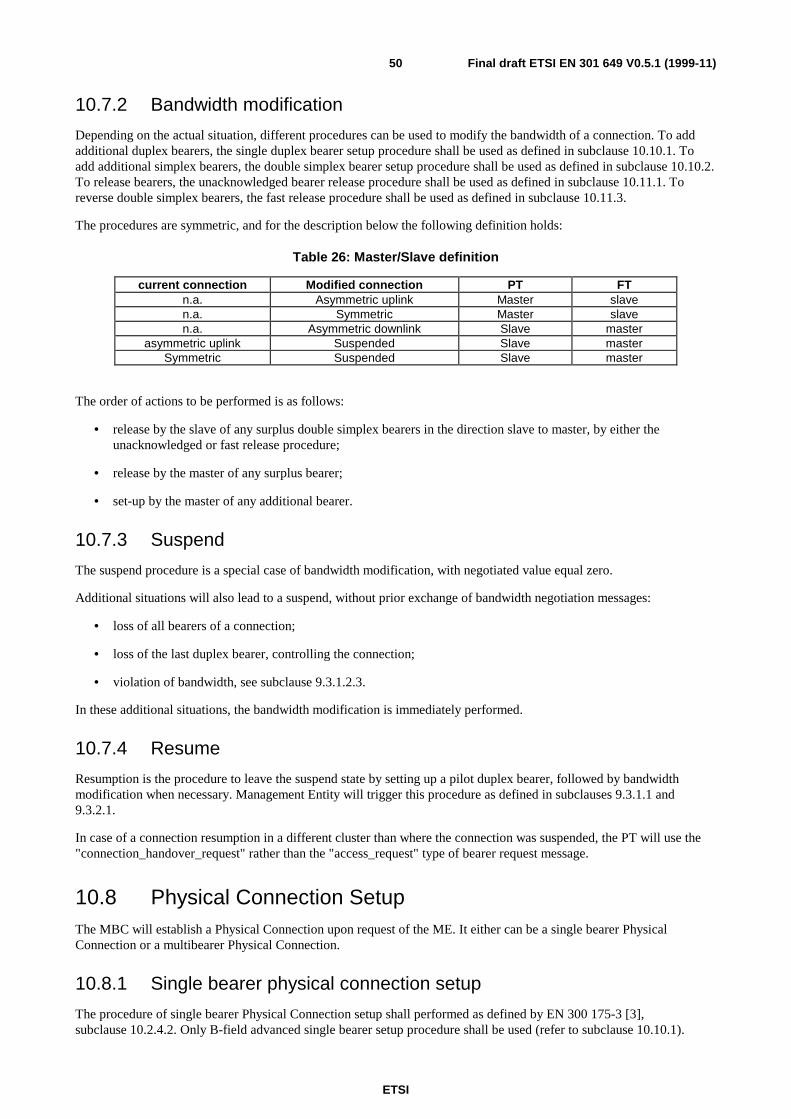
ETSI
Final draft ETSI EN 301 649 V0.5.1 (1999-11)50
10.7.2 Bandwidth modification
Depending on the actual situation, different procedures can be used to modify the bandwidth of a connection. To addadditional duplex bearers, the single duplex bearer setup procedure shall be used as defined in subclause 10.10.1. Toadd additional simplex bearers, the double simplex bearer setup procedure shall be used as defined in subclause 10.10.2.To release bearers, the unacknowledged bearer release procedure shall be used as defined in subclause 10.11.1. Toreverse double simplex bearers, the fast release procedure shall be used as defined in subclause 10.11.3.
The procedures are symmetric, and for the description below the following definition holds:
Table 26: Master/Slave definition
current connection Modified connection PT FTn.a. Asymmetric uplink Master slaven.a. Symmetric Master slaven.a. Asymmetric downlink Slave master
asymmetric uplink Suspended Slave masterSymmetric Suspended Slave master
The order of actions to be performed is as follows:
• release by the slave of any surplus double simplex bearers in the direction slave to master, by either theunacknowledged or fast release procedure;
• release by the master of any surplus bearer;
• set-up by the master of any additional bearer.
10.7.3 Suspend
The suspend procedure is a special case of bandwidth modification, with negotiated value equal zero.
Additional situations will also lead to a suspend, without prior exchange of bandwidth negotiation messages:
• loss of all bearers of a connection;
• loss of the last duplex bearer, controlling the connection;
• violation of bandwidth, see subclause 9.3.1.2.3.
In these additional situations, the bandwidth modification is immediately performed.
10.7.4 Resume
Resumption is the procedure to leave the suspend state by setting up a pilot duplex bearer, followed by bandwidthmodification when necessary. Management Entity will trigger this procedure as defined in subclauses 9.3.1.1 and9.3.2.1.
In case of a connection resumption in a different cluster than where the connection was suspended, the PT will use the"connection_handover_request" rather than the "access_request" type of bearer request message.
10.8 Physical Connection SetupThe MBC will establish a Physical Connection upon request of the ME. It either can be a single bearer PhysicalConnection or a multibearer Physical Connection.
10.8.1 Single bearer physical connection setup
The procedure of single bearer Physical Connection setup shall performed as defined by EN 300 175-3 [3],subclause 10.2.4.2. Only B-field advanced single bearer setup procedure shall be used (refer to subclause 10.10.1).
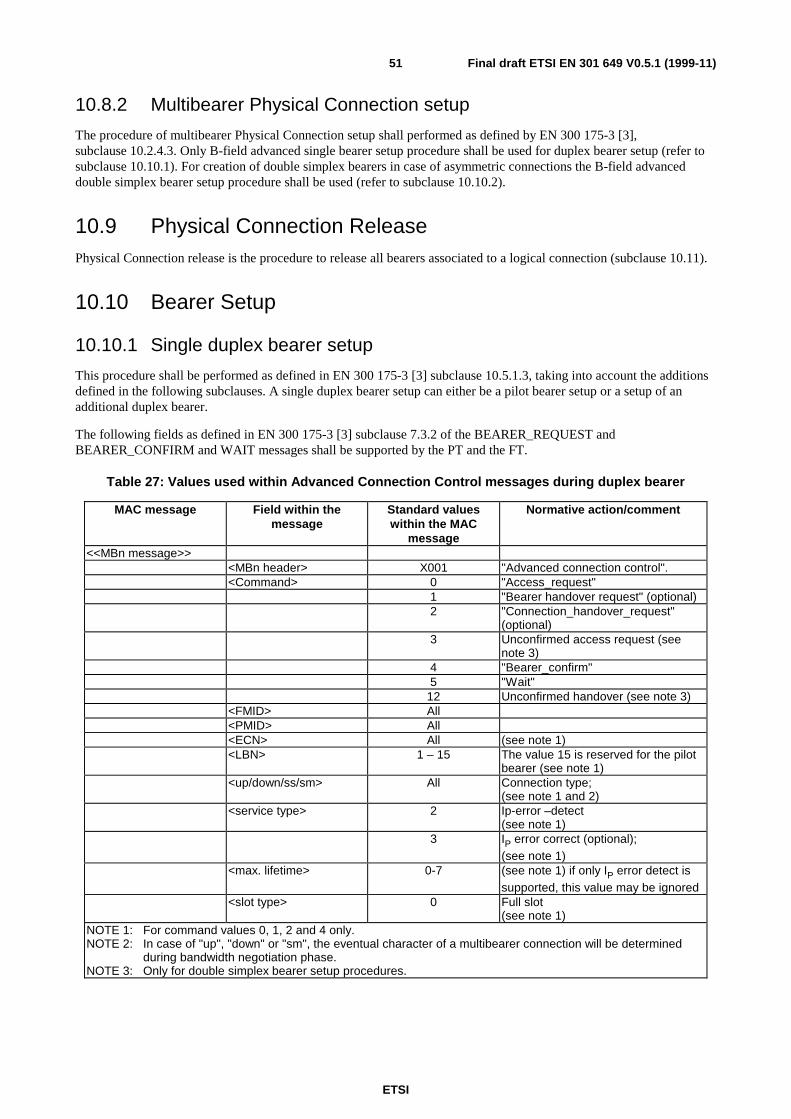
ETSI
Final draft ETSI EN 301 649 V0.5.1 (1999-11)51
10.8.2 Multibearer Physical Connection setup
The procedure of multibearer Physical Connection setup shall performed as defined by EN 300 175-3 [3],subclause 10.2.4.3. Only B-field advanced single bearer setup procedure shall be used for duplex bearer setup (refer tosubclause 10.10.1). For creation of double simplex bearers in case of asymmetric connections the B-field advanceddouble simplex bearer setup procedure shall be used (refer to subclause 10.10.2).
10.9 Physical Connection ReleasePhysical Connection release is the procedure to release all bearers associated to a logical connection (subclause 10.11).
10.10 Bearer Setup
10.10.1 Single duplex bearer setup
This procedure shall be performed as defined in EN 300 175-3 [3] subclause 10.5.1.3, taking into account the additionsdefined in the following subclauses. A single duplex bearer setup can either be a pilot bearer setup or a setup of anadditional duplex bearer.
The following fields as defined in EN 300 175-3 [3] subclause 7.3.2 of the BEARER_REQUEST andBEARER_CONFIRM and WAIT messages shall be supported by the PT and the FT.
Table 27: Values used within Advanced Connection Control messages during duplex bearer
MAC message Field within themessage
Standard valueswithin the MAC
message
Normative action/comment
<<MBn message>><MBn header> X001 "Advanced connection control".<Command> 0 "Access_request"
1 "Bearer handover request" (optional)2 "Connection_handover_request"
(optional)3 Unconfirmed access request (see
note 3)4 "Bearer_confirm"5 "Wait"
12 Unconfirmed handover (see note 3)<FMID> All<PMID> All<ECN> All (see note 1)<LBN> 1 – 15 The value 15 is reserved for the pilot
bearer (see note 1)<up/down/ss/sm> All Connection type;
(see note 1 and 2)<service type> 2 Ip-error –detect
(see note 1)3 IP error correct (optional);
(see note 1)<max. lifetime> 0-7 (see note 1) if only IP error detect is
supported, this value may be ignored<slot type> 0 Full slot
(see note 1)NOTE 1: For command values 0, 1, 2 and 4 only.NOTE 2: In case of "up", "down" or "sm", the eventual character of a multibearer connection will be determined
during bandwidth negotiation phase.NOTE 3: Only for double simplex bearer setup procedures.
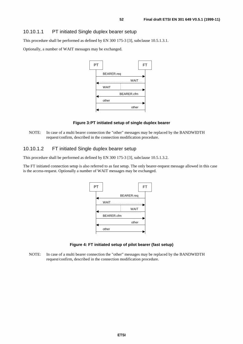
ETSI
Final draft ETSI EN 301 649 V0.5.1 (1999-11)52
10.10.1.1 PT initiated Single duplex bearer setup
This procedure shall be performed as defined by EN 300 175-3 [3], subclause 10.5.1.3.1.
Optionally, a number of WAIT messages may be exchanged.
BEARER.req
BEARER.cfm
PT
WAIT
WAIT
FT
other
other
Figure 3:PT initiated setup of single duplex bearer
NOTE: In case of a multi bearer connection the "other" messages may be replaced by the BANDWIDTHrequest/confirm, described in the connection modification procedure.
10.10.1.2 FT initiated Single duplex bearer setup
This procedure shall be performed as defined by EN 300 175-3 [3], subclause 10.5.1.3.2.
The FT initiated connection setup is also referred to as fast setup. The only bearer-request message allowed in this caseis the access-request. Optionally a number of WAIT messages may be exchanged.
BEARER.req
BEARER.cfm
PT
WAIT
WAIT
FT
other
other
Figure 4: FT initiated setup of pilot bearer (fast setup)
NOTE: In case of a multi bearer connection the "other" messages may be replaced by the BANDWIDTHrequest/confirm, described in the connection modification procedure.
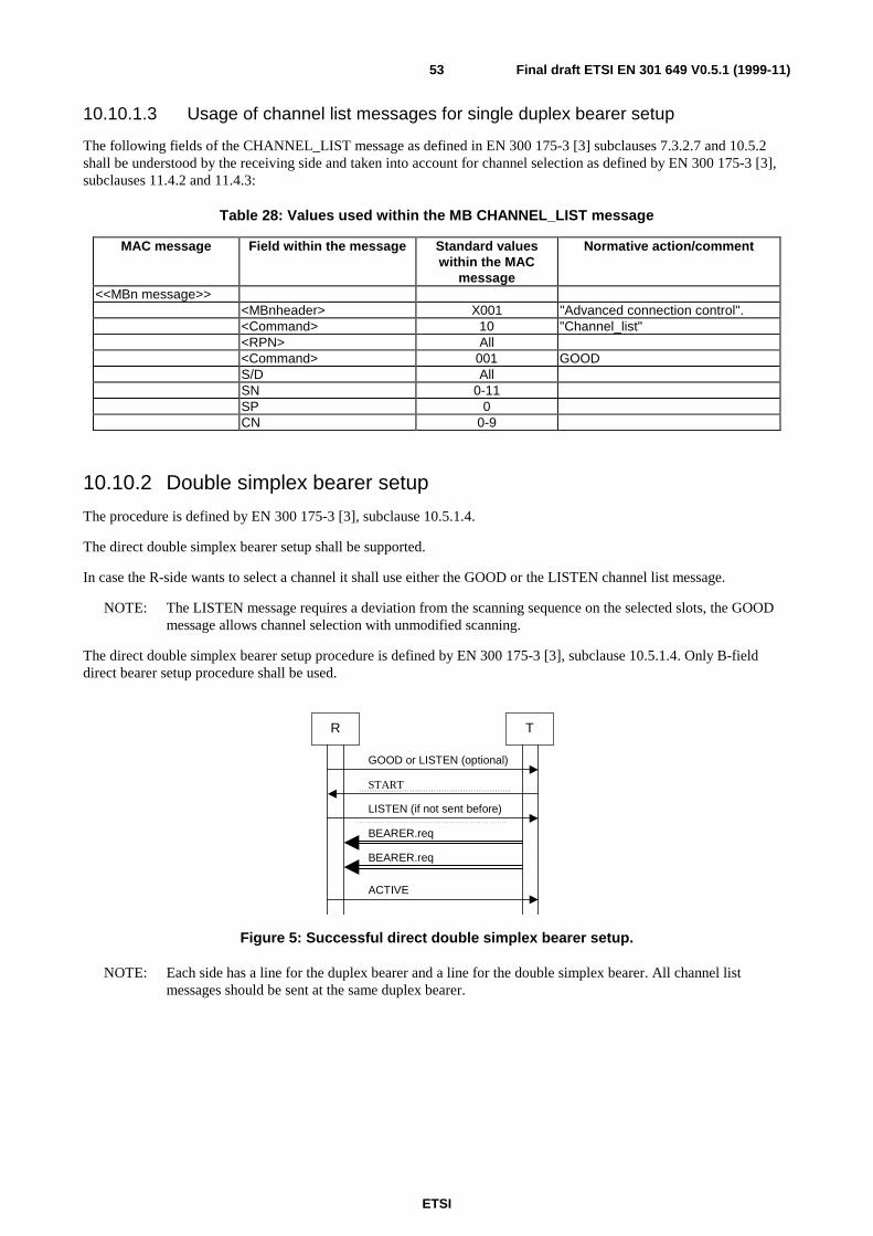
ETSI
Final draft ETSI EN 301 649 V0.5.1 (1999-11)53
10.10.1.3 Usage of channel list messages for single duplex bearer setup
The following fields of the CHANNEL_LIST message as defined in EN 300 175-3 [3] subclauses 7.3.2.7 and 10.5.2shall be understood by the receiving side and taken into account for channel selection as defined by EN 300 175-3 [3],subclauses 11.4.2 and 11.4.3:
Table 28: Values used within the MB CHANNEL_LIST message
MAC message Field within the message Standard valueswithin the MAC
message
Normative action/comment
<<MBn message>><MBnheader> X001 "Advanced connection control".<Command> 10 "Channel_list"<RPN> All<Command> 001 GOODS/D AllSN 0-11SP 0CN 0-9
10.10.2 Double simplex bearer setup
The procedure is defined by EN 300 175-3 [3], subclause 10.5.1.4.
The direct double simplex bearer setup shall be supported.
In case the R-side wants to select a channel it shall use either the GOOD or the LISTEN channel list message.
NOTE: The LISTEN message requires a deviation from the scanning sequence on the selected slots, the GOODmessage allows channel selection with unmodified scanning.
The direct double simplex bearer setup procedure is defined by EN 300 175-3 [3], subclause 10.5.1.4. Only B-fielddirect bearer setup procedure shall be used.
R T
START
GOOD or LISTEN (optional)
BEARER.req
BEARER.req
LISTEN (if not sent before)
ACTIVE
Figure 5: Successful direct double simplex bearer setup.
NOTE: Each side has a line for the duplex bearer and a line for the double simplex bearer. All channel listmessages should be sent at the same duplex bearer.
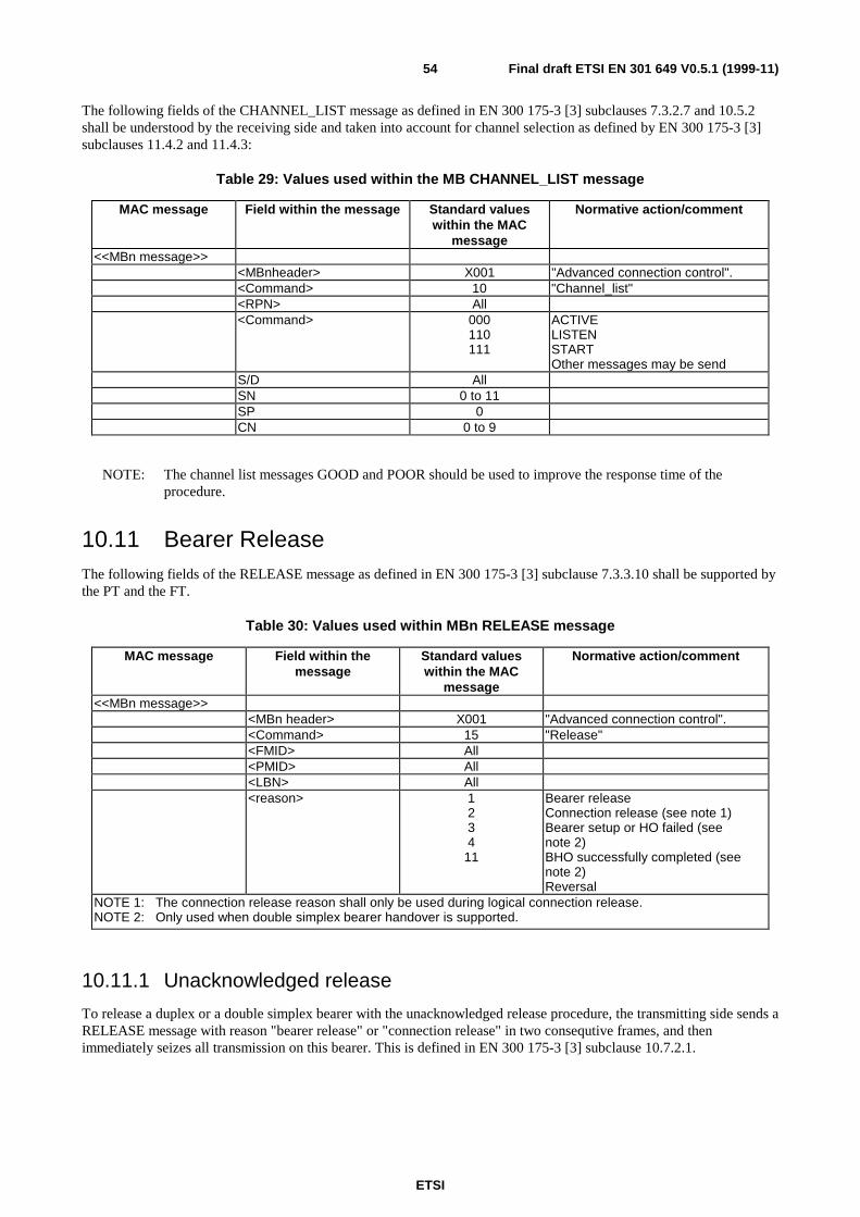
ETSI
Final draft ETSI EN 301 649 V0.5.1 (1999-11)54
The following fields of the CHANNEL_LIST message as defined in EN 300 175-3 [3] subclauses 7.3.2.7 and 10.5.2shall be understood by the receiving side and taken into account for channel selection as defined by EN 300 175-3 [3]subclauses 11.4.2 and 11.4.3:
Table 29: Values used within the MB CHANNEL_LIST message
MAC message Field within the message Standard valueswithin the MAC
message
Normative action/comment
<<MBn message>><MBnheader> X001 "Advanced connection control".<Command> 10 "Channel_list"<RPN> All<Command> 000
110111
ACTIVELISTENSTARTOther messages may be send
S/D AllSN 0 to 11SP 0CN 0 to 9
NOTE: The channel list messages GOOD and POOR should be used to improve the response time of theprocedure.
10.11 Bearer ReleaseThe following fields of the RELEASE message as defined in EN 300 175-3 [3] subclause 7.3.3.10 shall be supported bythe PT and the FT.
Table 30: Values used within MBn RELEASE message
MAC message Field within themessage
Standard valueswithin the MAC
message
Normative action/comment
<<MBn message>><MBn header> X001 "Advanced connection control".<Command> 15 "Release"<FMID> All<PMID> All<LBN> All<reason> 1
234
11
Bearer releaseConnection release (see note 1)Bearer setup or HO failed (seenote 2)BHO successfully completed (seenote 2)Reversal
NOTE 1: The connection release reason shall only be used during logical connection release.NOTE 2: Only used when double simplex bearer handover is supported.
10.11.1 Unacknowledged release
To release a duplex or a double simplex bearer with the unacknowledged release procedure, the transmitting side sends aRELEASE message with reason "bearer release" or "connection release" in two consequtive frames, and thenimmediately seizes all transmission on this bearer. This is defined in EN 300 175-3 [3] subclause 10.7.2.1.
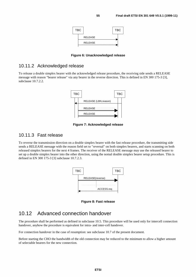
ETSI
Final draft ETSI EN 301 649 V0.5.1 (1999-11)55
RELEASE
TBC
RELEASE
TBC
Figure 6: Unacknowledged release
10.11.2 Acknowledged release
To release a double simplex bearer with the acknowledged release procedure, the receiving side sends a RELEASEmessage with reason "bearer release" via any bearer in the reverse direction. This is defined in EN 300 175-3 [3],subclause 10.7.2.2.
RELEASE
TBC
RELEASE
TBC
RELEASE (LBN,reason)
Figure 7: Acknowledged release
10.11.3 Fast release
To reverse the transmission direction on a double simplex bearer with the fast release procedure, the transmitting sidesends a RELEASE message with the reason field set to "reversal" on both simplex bearers, and starts scanning on bothreleased simplex bearers for the next 4 frames. The receiver of the RELEASE message may use the released bearer toset up a double simplex bearer into the other direction, using the nomal double simplex bearer setup procedure. This isdefined in EN 300 175-3 [3] subclause 10.7.2.3.
RELEASE(reverse)
TBC
ACCESS.req
TBC
Figure 8: Fast release
10.12 Advanced connection handoverThe procedure shall be performed as defined in subclause 10.5. This procedure will be used only for intercell connectionhandover, anyhow the procedure is equivalent for intra- and inter-cell handover.
For connection handover in the case of resumption: see subclause 10.7 of the present document.
Before starting the CHO the bandwidth of the old connection may be reduced to the minimum to allow a higher amountof selectable bearers for the new connection.
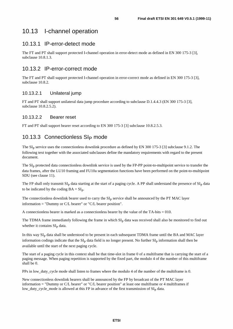
ETSI
Final draft ETSI EN 301 649 V0.5.1 (1999-11)56
10.13 I-channel operation
10.13.1 IP-error-detect mode
The FT and PT shall support protected I-channel operation in error-detect mode as defined in EN 300 175-3 [3],subclause 10.8.1.3.
10.13.2 IP-error-correct mode
The FT and PT shall support protected I-channel operation in error-correct mode as defined in EN 300 175-3 [3],subclause 10.8.2.
10.13.2.1 Unilateral jump
FT and PT shall support unilateral data jump procedure according to subclause D.1.4.4.3 (EN 300 175-3 [3],subclause 10.8.2.5.2).
10.13.2.2 Bearer reset
FT and PT shall support bearer reset according to EN 300 175-3 [3] subclause 10.8.2.5.3.
10.13.3 Connectionless SIP mode
The SIP service uses the connectionless downlink procedure as defined by EN 300 175-3 [3] subclause 9.1.2. The
following text together with the associated subclauses define the mandatory requirements with regard to the presentdocument.
The SIP protected data connectionless downlink service is used by the FP-PP point-to-multipoint service to transfer the
data frames, after the LU10 framing and FU10a segmentation functions have been performed on the point-to-multipointSDU (see clause 11).
The FP shall only transmit SIP data starting at the start of a paging cycle. A PP shall understand the presence of SIP data
to be indicated by the coding BA = SIP.
The connectionless downlink bearer used to carry the SIP service shall be announced by the PT MAC layer
information = "Dummy or C/L bearer" or "C/L bearer position".
A connectionless bearer is marked as a connectionless bearer by the value of the TA-bits = 010.
The TDMA frame immediately following the frame in which SIP data was received shall also be monitored to find out
whether it contains SIP data.
In this way SIP data shall be understood to be present in each subsequent TDMA frame until the BA and MAC layer
information codings indicate that the SIP data field is no longer present. No further SIP information shall then be
available until the start of the next paging cycle.
The start of a paging cycle in this context shall be that time-slot in frame 0 of a multiframe that is carrying the start of apaging message. When paging repetition is supported by the fixed part, the modulo 4 of the number of this multiframeshall be 0.
PPs in low_duty_cycle mode shall listen to frames where the modulo 4 of the number of the multiframe is 0.
New connectionless downlink bearers shall be announced by the FP by broadcast of the PT MAC layerinformation = "Dummy or C/L bearer" or "C/L bearer position" at least one multiframe or 4 multiframes iflow_duty_cycle_mode is allowed at this FP in advance of the first transmission of SIP data.
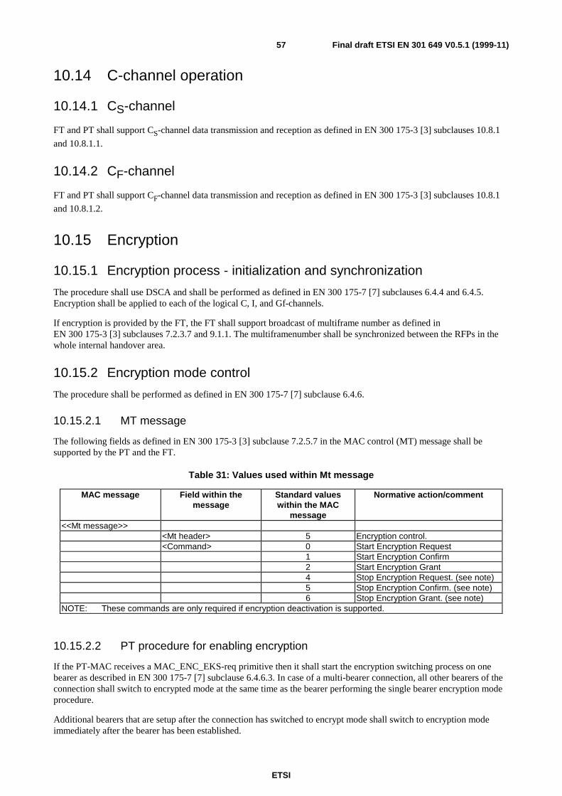
ETSI
Final draft ETSI EN 301 649 V0.5.1 (1999-11)57
10.14 C-channel operation
10.14.1 CS-channel
FT and PT shall support CS-channel data transmission and reception as defined in EN 300 175-3 [3] subclauses 10.8.1
and 10.8.1.1.
10.14.2 CF-channel
FT and PT shall support CF-channel data transmission and reception as defined in EN 300 175-3 [3] subclauses 10.8.1
and 10.8.1.2.
10.15 Encryption
10.15.1 Encryption process - initialization and synchronization
The procedure shall use DSCA and shall be performed as defined in EN 300 175-7 [7] subclauses 6.4.4 and 6.4.5.Encryption shall be applied to each of the logical C, I, and Gf-channels.
If encryption is provided by the FT, the FT shall support broadcast of multiframe number as defined inEN 300 175-3 [3] subclauses 7.2.3.7 and 9.1.1. The multiframenumber shall be synchronized between the RFPs in thewhole internal handover area.
10.15.2 Encryption mode control
The procedure shall be performed as defined in EN 300 175-7 [7] subclause 6.4.6.
10.15.2.1 MT message
The following fields as defined in EN 300 175-3 [3] subclause 7.2.5.7 in the MAC control (MT) message shall besupported by the PT and the FT.
Table 31: Values used within Mt message
MAC message Field within themessage
Standard valueswithin the MAC
message
Normative action/comment
<<Mt message>><Mt header> 5 Encryption control.<Command> 0 Start Encryption Request
1 Start Encryption Confirm2 Start Encryption Grant4 Stop Encryption Request. (see note)5 Stop Encryption Confirm. (see note)6 Stop Encryption Grant. (see note)
NOTE: These commands are only required if encryption deactivation is supported.
10.15.2.2 PT procedure for enabling encryption
If the PT-MAC receives a MAC_ENC_EKS-req primitive then it shall start the encryption switching process on onebearer as described in EN 300 175-7 [7] subclause 6.4.6.3. In case of a multi-bearer connection, all other bearers of theconnection shall switch to encrypted mode at the same time as the bearer performing the single bearer encryption modeprocedure.
Additional bearers that are setup after the connection has switched to encrypt mode shall switch to encryption modeimmediately after the bearer has been established.
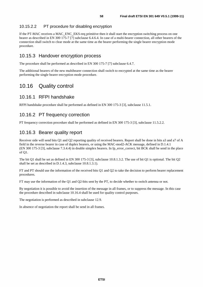
ETSI
Final draft ETSI EN 301 649 V0.5.1 (1999-11)58
10.15.2.2 PT procedure for disabling encryption
If the PT-MAC receives a MAC_ENC_EKS-req primitive then it shall start the encryption switching process on onebearer as described in EN 300 175-7 [7] subclause 6.4.6.4. In case of a multi-bearer connection, all other bearers of theconnection shall switch to clear mode at the same time as the bearer performing the single bearer encryption modeprocedure.
10.15.3 Handover encryption process
The procedure shall be performed as described in EN 300 175-7 [7] subclause 6.4.7.
The additional bearers of the new multibearer connection shall switch to encrypted at the same time as the bearerperforming the single bearer encryption mode procedure.
10.16 Quality control
10.16.1 RFPI handshake
RFPI handshake procedure shall be performed as defined in EN 300 175-3 [3], subclause 11.5.1.
10.16.2 PT frequency correction
PT frequency correction procedure shall be performed as defined in EN 300 175-3 [3], subclause 11.5.2.2.
10.16.3 Bearer quality report
Receiver side will send bits Q1 and Q2 reporting quality of received bearers. Report shall be done in bits a3 and a7 of Afield in the reverse bearer in case of duplex bearers, or using the MAC-mod2-ACK message, defined in D.1.4.1(EN 300 175-3 [3], subclause 7.3.4.4) in double simplex bearers. In Ip_error_correct, bit BCK shall be send in the placeof Q1.
The bit Q1 shall be set as defined in EN 300 175-3 [3], subclause 10.8.1.3.2. The use of bit Q1 is optional. The bit Q2shall be set as described in D.1.4.3, subclause 10.8.1.3.1).
FT and PT should use the information of the received bits Q1 and Q2 to take the decision to perform bearer replacementprocedures.
FT may use the information of the Q1 and Q2-bits sent by the PT, to decide whether to switch antenna or not.
By negotiation it is possible to avoid the insertion of the message in all frames, or to suppress the message. In this casethe procedure described in subclause 10.16.4 shall be used for quality control purposes.
The negotiation is performed as described in subclause 12.9.
In absence of negotiation the report shall be send in all frames.
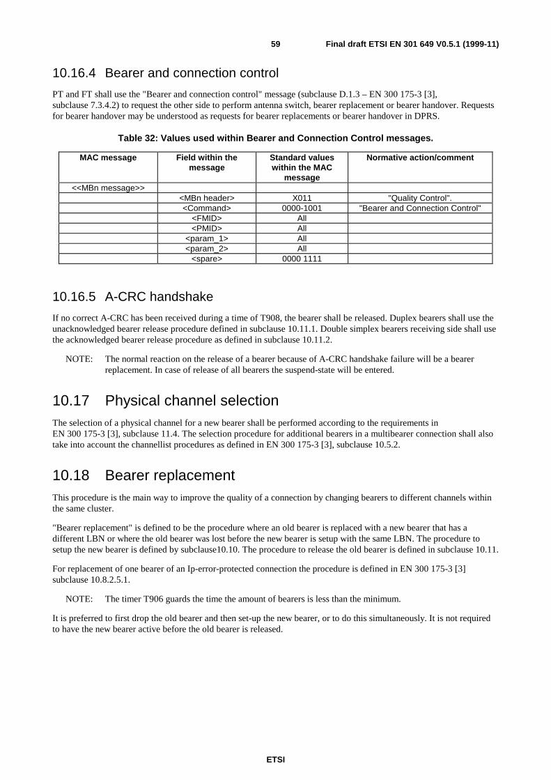
ETSI
Final draft ETSI EN 301 649 V0.5.1 (1999-11)59
10.16.4 Bearer and connection control
PT and FT shall use the "Bearer and connection control" message (subclause D.1.3 – EN 300 175-3 [3],subclause 7.3.4.2) to request the other side to perform antenna switch, bearer replacement or bearer handover. Requestsfor bearer handover may be understood as requests for bearer replacements or bearer handover in DPRS.
Table 32: Values used within Bearer and Connection Control messages.
MAC message Field within themessage
Standard valueswithin the MAC
message
Normative action/comment
<<MBn message>><MBn header> X011 "Quality Control".<Command> 0000-1001 "Bearer and Connection Control"
<FMID> All<PMID> All
<param_1> All<param_2> All
<spare> 0000 1111
10.16.5 A-CRC handshake
If no correct A-CRC has been received during a time of T908, the bearer shall be released. Duplex bearers shall use theunacknowledged bearer release procedure defined in subclause 10.11.1. Double simplex bearers receiving side shall usethe acknowledged bearer release procedure as defined in subclause 10.11.2.
NOTE: The normal reaction on the release of a bearer because of A-CRC handshake failure will be a bearerreplacement. In case of release of all bearers the suspend-state will be entered.
10.17 Physical channel selectionThe selection of a physical channel for a new bearer shall be performed according to the requirements inEN 300 175-3 [3], subclause 11.4. The selection procedure for additional bearers in a multibearer connection shall alsotake into account the channellist procedures as defined in EN 300 175-3 [3], subclause 10.5.2.
10.18 Bearer replacementThis procedure is the main way to improve the quality of a connection by changing bearers to different channels withinthe same cluster.
"Bearer replacement" is defined to be the procedure where an old bearer is replaced with a new bearer that has adifferent LBN or where the old bearer was lost before the new bearer is setup with the same LBN. The procedure tosetup the new bearer is defined by subclause10.10. The procedure to release the old bearer is defined in subclause 10.11.
For replacement of one bearer of an Ip-error-protected connection the procedure is defined in EN 300 175-3 [3]subclause 10.8.2.5.1.
NOTE: The timer T906 guards the time the amount of bearers is less than the minimum.
It is preferred to first drop the old bearer and then set-up the new bearer, or to do this simultaneously. It is not requiredto have the new bearer active before the old bearer is released.
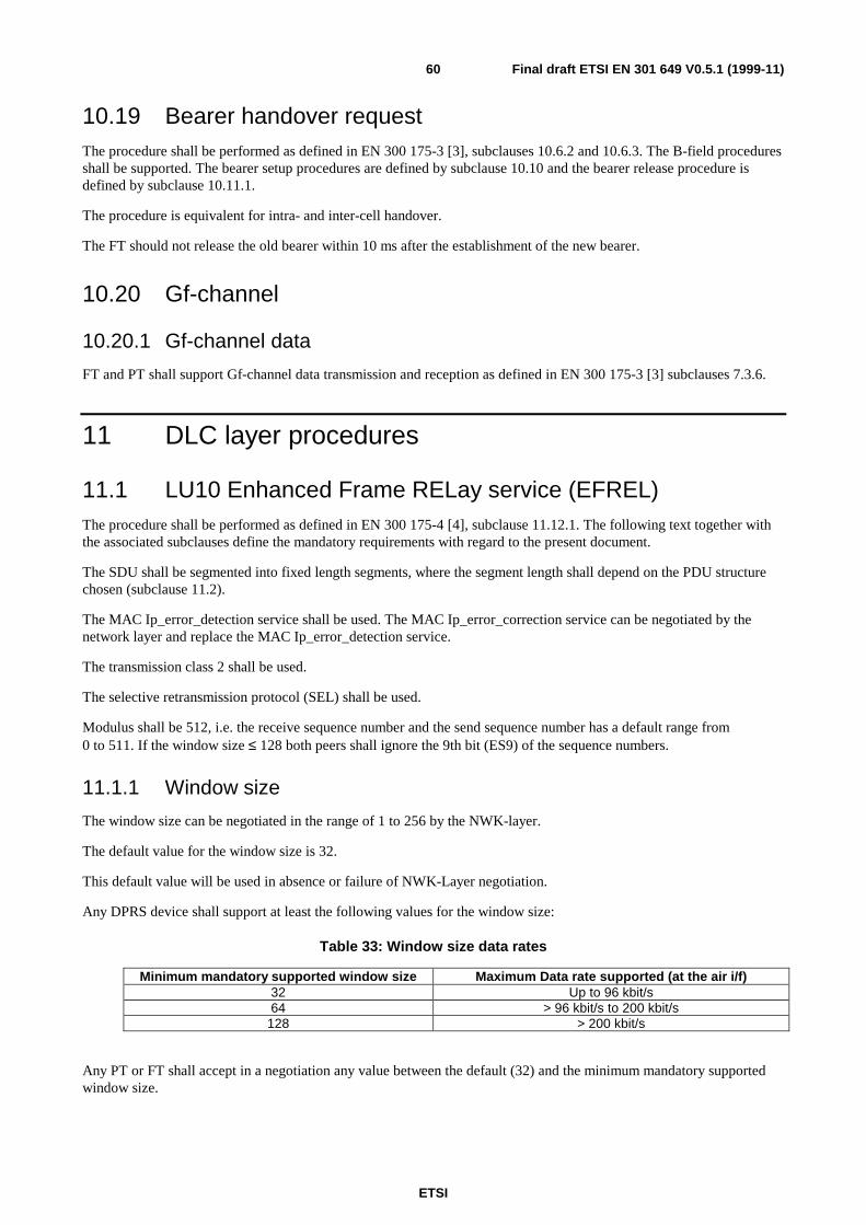
ETSI
Final draft ETSI EN 301 649 V0.5.1 (1999-11)60
10.19 Bearer handover requestThe procedure shall be performed as defined in EN 300 175-3 [3], subclauses 10.6.2 and 10.6.3. The B-field proceduresshall be supported. The bearer setup procedures are defined by subclause 10.10 and the bearer release procedure isdefined by subclause 10.11.1.
The procedure is equivalent for intra- and inter-cell handover.
The FT should not release the old bearer within 10 ms after the establishment of the new bearer.
10.20 Gf-channel
10.20.1 Gf-channel data
FT and PT shall support Gf-channel data transmission and reception as defined in EN 300 175-3 [3] subclauses 7.3.6.
11 DLC layer procedures
11.1 LU10 Enhanced Frame RELay service (EFREL)The procedure shall be performed as defined in EN 300 175-4 [4], subclause 11.12.1. The following text together withthe associated subclauses define the mandatory requirements with regard to the present document.
The SDU shall be segmented into fixed length segments, where the segment length shall depend on the PDU structurechosen (subclause 11.2).
The MAC Ip_error_detection service shall be used. The MAC Ip_error_correction service can be negotiated by thenetwork layer and replace the MAC Ip_error_detection service.
The transmission class 2 shall be used.
The selective retransmission protocol (SEL) shall be used.
Modulus shall be 512, i.e. the receive sequence number and the send sequence number has a default range from0 to 511. If the window size ≤ 128 both peers shall ignore the 9th bit (ES9) of the sequence numbers.
11.1.1 Window size
The window size can be negotiated in the range of 1 to 256 by the NWK-layer.
The default value for the window size is 32.
This default value will be used in absence or failure of NWK-Layer negotiation.
Any DPRS device shall support at least the following values for the window size:
Table 33: Window size data rates
Minimum mandatory supported window size Maximum Data rate supported (at the air i/f)32 Up to 96 kbit/s64 > 96 kbit/s to 200 kbit/s
128 > 200 kbit/s
Any PT or FT shall accept in a negotiation any value between the default (32) and the minimum mandatory supportedwindow size.
ETSI
Final draft ETSI EN 301 649 V0.5.1 (1999-11)61
11.1.2 U-plane transmission class 2
11.1.2.1 Sending side procedures
The procedure shall be performed as defined in D.2.5, subclause 14.3.4.1. The following text together with theassociated subclauses define the mandatory requirements with regard to the present document.
The sequence numbers shall be added using the rules defined below.
If a connection oriented MAC service is used (see EN 300 175-3 [3], subclause 5.6), then the send sequence numbershall be set to zero at the start of the MAC connection, and this value shall be used for the first transmitted frame overthat MAC connection. The send sequence numbers of successive frames shall be contiguous (Modulus) during thelifetime of that MAC connection.
If a connectionless MAC service is used (see EN 300 175-3 [3], subclauses 5.7 and 9.1.2.2), then the send sequencenumber of the first segment of a DLC SDU may be arbitrarily chosen. The send sequence numbers of successive framesshall be contiguous (Modulus) within one DLC SDU.
At the transmitting side a complete SDU shall be received in a DL_U_DATA-req primitive. The SDU shall be passed tothe segmenting function and segmented into an integral number of segments. The last segment shall be filled with filloctets if necessary. The information content of each PDU shall be marked using the length indicator as described insubclause D.2.4.
Several PDUs may be submitted once to the MAC layer in a single MAC_CO_DATA-req primitive in response to eachMAC_CO_DTR-ind primitive. The number of PDUs shall be less than or equal to the maximum number requested inthe MAC_CO_DTR-ind primitive.
11.1.2.2 Receiving side procedure
The procedure shall be performed as defined in D.2.5. The following text together with the associated subclausesdefines the mandatory requirements with regard to the present document.
The receive sequence number shall be set to 0 at service establishment.
Several PDUs may be received from the MAC layer in a single MAC_CO_DATA-ind primitive. The receive side shallre-order the PDUs using the send sequence numbers. The receive side shall then search for SDU boundaries using theextended more bit as defined in subclause D.2.2.
A complete SDU shall be assumed to exist, and shall be passed to the IWU using a DL_U_DATA-ind primitive whenthe following conditions are satisfied:
• two successive boundaries have been identified using the extended More bit (i.e. there are no intermediateboundaries);
• PDUs have been successfully received for all of the sequence numbers that lie between those boundaries.
11.2 FU 10 framing (FU10a, FU10b, FU10c)The procedure shall be performed as defined in subclause D.2.1. The following text together with the associatedsubclauses defines the mandatory requirements with regard to the present document.
11.2.1 FU10a
FU10a frames with total length of 32 octets shall be used for the forward path of the unidirectional link.
11.2.2 FU10b
FU10b frames with total length of 32 octets can only be used for bi-directional links and can only used after negotiationby the network layer, see subclause 12.5.
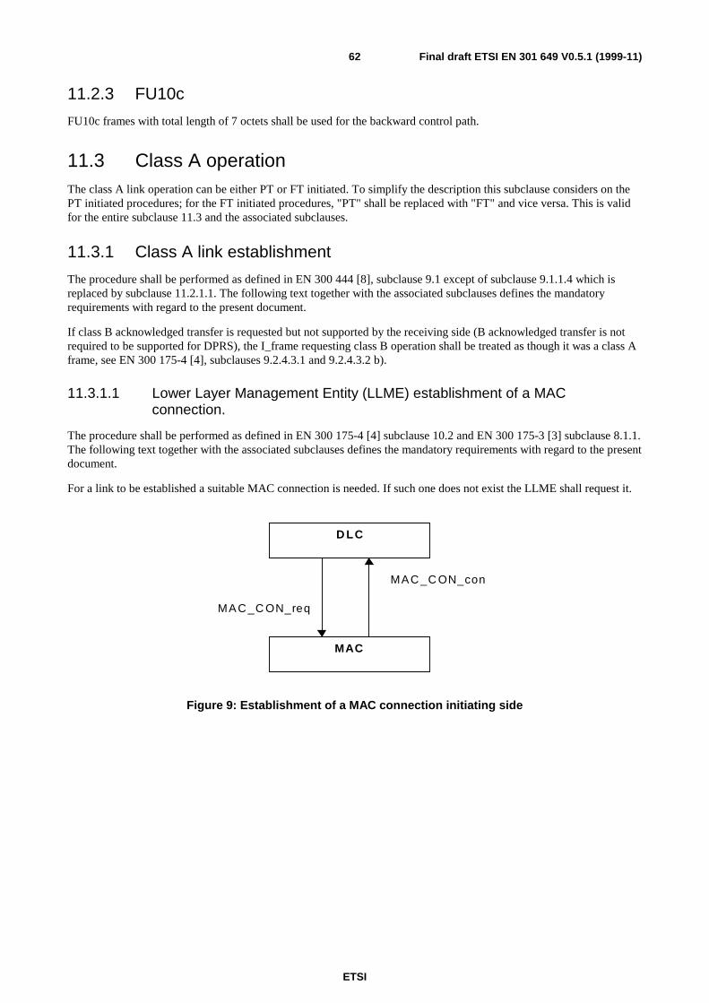
ETSI
Final draft ETSI EN 301 649 V0.5.1 (1999-11)62
11.2.3 FU10c
FU10c frames with total length of 7 octets shall be used for the backward control path.
11.3 Class A operationThe class A link operation can be either PT or FT initiated. To simplify the description this subclause considers on thePT initiated procedures; for the FT initiated procedures, "PT" shall be replaced with "FT" and vice versa. This is validfor the entire subclause 11.3 and the associated subclauses.
11.3.1 Class A link establishment
The procedure shall be performed as defined in EN 300 444 [8], subclause 9.1 except of subclause 9.1.1.4 which isreplaced by subclause 11.2.1.1. The following text together with the associated subclauses defines the mandatoryrequirements with regard to the present document.
If class B acknowledged transfer is requested but not supported by the receiving side (B acknowledged transfer is notrequired to be supported for DPRS), the I_frame requesting class B operation shall be treated as though it was a class Aframe, see EN 300 175-4 [4], subclauses 9.2.4.3.1 and 9.2.4.3.2 b).
11.3.1.1 Lower Layer Management Entity (LLME) establishment of a MACconnection.
The procedure shall be performed as defined in EN 300 175-4 [4] subclause 10.2 and EN 300 175-3 [3] subclause 8.1.1.The following text together with the associated subclauses defines the mandatory requirements with regard to the presentdocument.
For a link to be established a suitable MAC connection is needed. If such one does not exist the LLME shall request it.
D LC
MAC
MAC _C ON_req
MAC _C ON_con
Figure 9: Establishment of a MAC connection initiating side
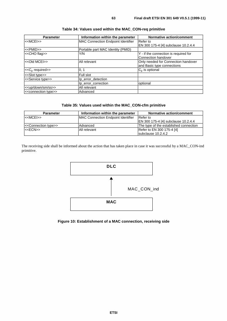
ETSI
Final draft ETSI EN 301 649 V0.5.1 (1999-11)63
Table 34: Values used within the MAC_CON-req primitive
Parameter Information within the parameter Normative action/comment<<MCEI>> MAC Connection Endpoint Identifier Refer to
EN 300 175-4 [4] subclause 10.2.4.4<<PMID>> Portable part MAC Identity (PMID)<<CHO flag>> Y/N Y - if the connection is required for
Connection handover<<Old MCEI>> All relevant Only needed for Connection handover
and Basic type connections<<CF required>> 0, 1 CF is optional
<<Slot type>> Full slot<<Service type>> Ip_error_detection
Ip_error_correction optional<<up/down/sm/ss>> All relevant<<connection type>> Advanced
Table 35: Values used within the MAC_CON-cfm primitive
Parameter Information within the parameter Normative action/comment<<MCEI>> MAC Connection Endpoint Identifier Refer to
EN 300 175-4 [4] subclause 10.2.4.4<<Connection type>> Advanced The type of the established connection<<ECN>> All relevant Refer to EN 300 175-4 [4]
subclause 10.2.4.2
The receiving side shall be informed about the action that has taken place in case it was successful by a MAC_CON-indprimitive.
DLC
MAC
MAC_CON_ind
Figure 10: Establishment of a MAC connection, receiving side
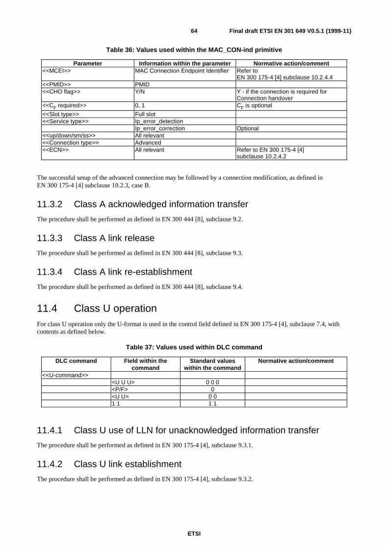
ETSI
Final draft ETSI EN 301 649 V0.5.1 (1999-11)64
Table 36: Values used within the MAC_CON-ind primitive
Parameter Information within the parameter Normative action/comment<<MCEI>> MAC Connection Endpoint Identifier Refer to
EN 300 175-4 [4] subclause 10.2.4.4<<PMID>> PMID<<CHO flag>> Y/N Y - if the connection is required for
Connection handover<<CF required>> 0, 1 CF is optional
<<Slot type>> Full slot<<Service type>> Ip_error_detection
Ip_error_correction Optional<<up/down/sm/ss>> All relevant<<Connection type>> Advanced<<ECN>> All relevant Refer to EN 300 175-4 [4]
subclause 10.2.4.2
The successful setup of the advanced connection may be followed by a connection modification, as defined inEN 300 175-4 [4] subclause 10.2.3, case B.
11.3.2 Class A acknowledged information transfer
The procedure shall be performed as defined in EN 300 444 [8], subclause 9.2.
11.3.3 Class A link release
The procedure shall be performed as defined in EN 300 444 [8], subclause 9.3.
11.3.4 Class A link re-establishment
The procedure shall be performed as defined in EN 300 444 [8], subclause 9.4.
11.4 Class U operationFor class U operation only the U-format is used in the control field defined in EN 300 175-4 [4], subclause 7.4, withcontents as defined below.
Table 37: Values used within DLC command
DLC command Field within thecommand
Standard valueswithin the command
Normative action/comment
<<U-command>><U U U> 0 0 0<P/F> 0<U U> 0 01 1 1 1
11.4.1 Class U use of LLN for unacknowledged information transfer
The procedure shall be performed as defined in EN 300 175-4 [4], subclause 9.3.1.
11.4.2 Class U link establishment
The procedure shall be performed as defined in EN 300 175-4 [4], subclause 9.3.2.
ETSI
Final draft ETSI EN 301 649 V0.5.1 (1999-11)65
11.4.3 Class U unacknowledged information transfer
The procedure shall be performed as defined in EN 300 175-4 [4], subclause 9.3.3.
11.4.4 Class U unacknowledged release
The procedure shall be performed as defined in EN 300 175-4 [4], subclause 9.3.4.
11.5 Lc frame delimiting and sequencing service
11.5.1 CS-channel fragmentation and recombination
The procedure shall be performed as defined in EN 300 175-4 [4], subclauses 6.1.2, 6.1.3 and 6.1.4, 6.1.4.2. Thefollowing text together with the associated subclauses define the mandatory requirements with regard to the presentdocument.
The complete frame shall be fragmented into 5 octet fragments.
11.5.2 CF-channel fragmentation and recombination
The CF-channel shall be operated according to the procedures defined in EN 300 175-4 [4] subclauses 6.1.2, 6.1.3, 6.1.4
and 6.1.4.1. The following text together with the associated subclauses define the mandatory requirements with regard tothe present document.
The complete frame shall be fragmented into 8 octet fragments.
11.5.3 Selection of logical channels (CS and CF)
The selection of the CF instead of the CS-channel for Lc operation, shall be done according to the conditions defined in
EN 300 175-4 [4], subclause 10.2.5.
11.6 Broadcast Lb service
11.6.1 Normal broadcast
The procedure shall be performed as defined in EN 300 175-4 [4], subclauses 6.2.1, 8.3.3.1, 9.4.1.1 and 9.4.1.2 andEN 300 175-3 [3], subclause 8.2.1. The following text together with the associated subclauses define the mandatoryrequirements with regard to the present document.
Short frame format (frame length = 3) and long frame format (frame length = 5) are required to be supported.
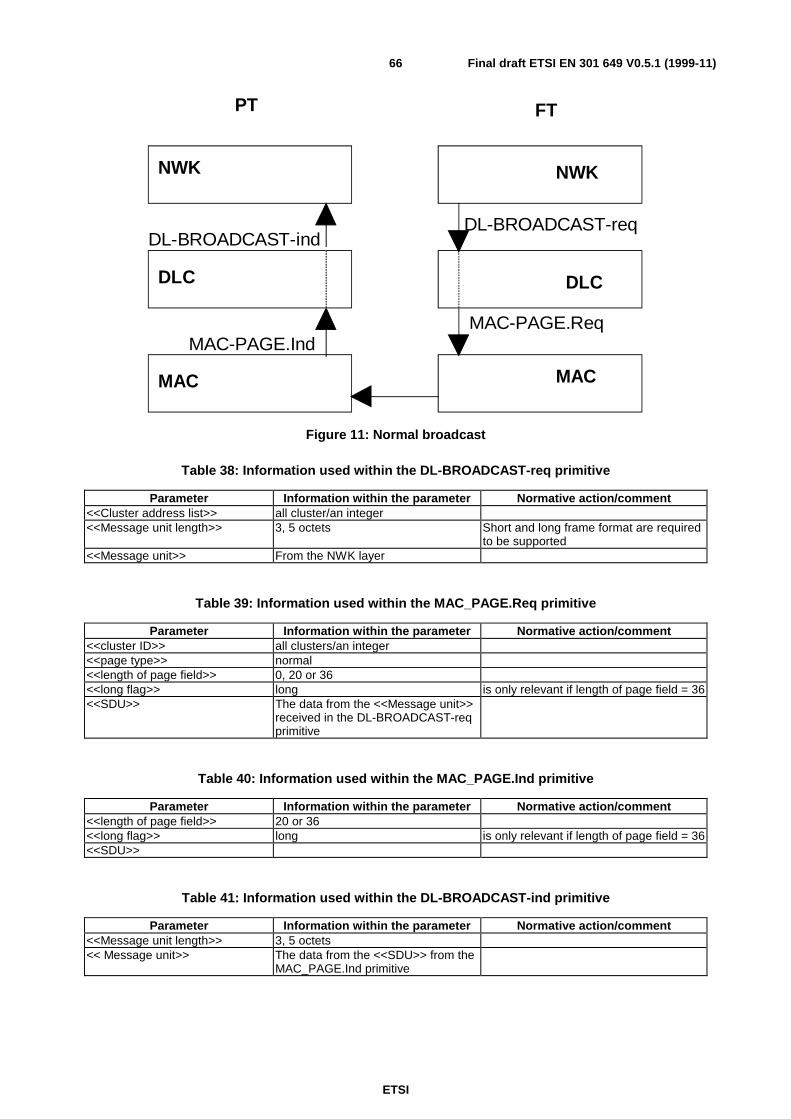
ETSI
Final draft ETSI EN 301 649 V0.5.1 (1999-11)66
DLC
MAC
MAC-PAGE.IndMAC-PAGE.Req
MAC
DLC
NWK NWK
DL-BROADCAST-indDL-BROADCAST-req
PT FT
Figure 11: Normal broadcast
Table 38: Information used within the DL-BROADCAST-req primitive
Parameter Information within the parameter Normative action/comment<<Cluster address list>> all cluster/an integer<<Message unit length>> 3, 5 octets Short and long frame format are required
to be supported<<Message unit>> From the NWK layer
Table 39: Information used within the MAC_PAGE.Req primitive
Parameter Information within the parameter Normative action/comment<<cluster ID>> all clusters/an integer<<page type>> normal<<length of page field>> 0, 20 or 36<<long flag>> long is only relevant if length of page field = 36<<SDU>> The data from the <<Message unit>>
received in the DL-BROADCAST-reqprimitive
Table 40: Information used within the MAC_PAGE.Ind primitive
Parameter Information within the parameter Normative action/comment<<length of page field>> 20 or 36<<long flag>> long is only relevant if length of page field = 36<<SDU>>
Table 41: Information used within the DL-BROADCAST-ind primitive
Parameter Information within the parameter Normative action/comment<<Message unit length>> 3, 5 octets<< Message unit>> The data from the <<SDU>> from the
MAC_PAGE.Ind primitive
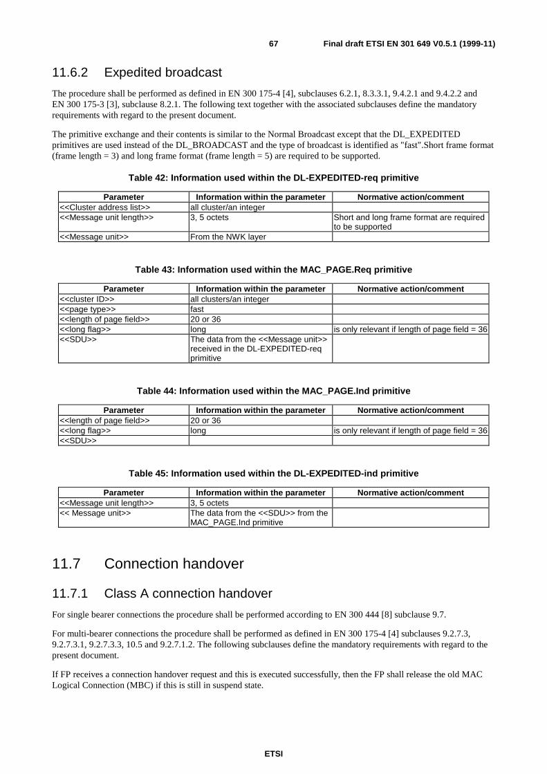
ETSI
Final draft ETSI EN 301 649 V0.5.1 (1999-11)67
11.6.2 Expedited broadcast
The procedure shall be performed as defined in EN 300 175-4 [4], subclauses 6.2.1, 8.3.3.1, 9.4.2.1 and 9.4.2.2 andEN 300 175-3 [3], subclause 8.2.1. The following text together with the associated subclauses define the mandatoryrequirements with regard to the present document.
The primitive exchange and their contents is similar to the Normal Broadcast except that the DL_EXPEDITEDprimitives are used instead of the DL_BROADCAST and the type of broadcast is identified as "fast".Short frame format(frame length = 3) and long frame format (frame length = 5) are required to be supported.
Table 42: Information used within the DL-EXPEDITED-req primitive
Parameter Information within the parameter Normative action/comment<<Cluster address list>> all cluster/an integer<<Message unit length>> 3, 5 octets Short and long frame format are required
to be supported<<Message unit>> From the NWK layer
Table 43: Information used within the MAC_PAGE.Req primitive
Parameter Information within the parameter Normative action/comment<<cluster ID>> all clusters/an integer<<page type>> fast<<length of page field>> 20 or 36<<long flag>> long is only relevant if length of page field = 36<<SDU>> The data from the <<Message unit>>
received in the DL-EXPEDITED-reqprimitive
Table 44: Information used within the MAC_PAGE.Ind primitive
Parameter Information within the parameter Normative action/comment<<length of page field>> 20 or 36<<long flag>> long is only relevant if length of page field = 36<<SDU>>
Table 45: Information used within the DL-EXPEDITED-ind primitive
Parameter Information within the parameter Normative action/comment<<Message unit length>> 3, 5 octets<< Message unit>> The data from the <<SDU>> from the
MAC_PAGE.Ind primitive
11.7 Connection handover
11.7.1 Class A connection handover
For single bearer connections the procedure shall be performed according to EN 300 444 [8] subclause 9.7.
For multi-bearer connections the procedure shall be performed as defined in EN 300 175-4 [4] subclauses 9.2.7.3,9.2.7.3.1, 9.2.7.3.3, 10.5 and 9.2.7.1.2. The following subclauses define the mandatory requirements with regard to thepresent document.
If FP receives a connection handover request and this is executed successfully, then the FP shall release the old MACLogical Connection (MBC) if this is still in suspend state.
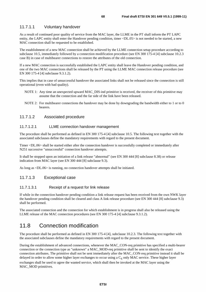
ETSI
Final draft ETSI EN 301 649 V0.5.1 (1999-11)68
11.7.1.1 Voluntary handover
As a result of continued poor quality of service from the MAC layer, the LLME in the PT shall inform the PT LAPCentity, the LAPC entity shall enter the Handover pending condition, timer <DL.05> is not needed to be started, a newMAC connection shall be requested to be established.
The establishment of a new MAC connection shall be achieved by the LLME connection setup procedure according tosubclause 10.5, immediately followed by a connection modification procedure (see EN 300 175-4 [4] subclause 10.2.3case B) in case of multibearer connections to restore the attributes of the old connection.
If a new MAC connection is successfully established the LAPC entity shall leave the Handover pending condition, andone of the two MAC connections shall be released by the PT using the LLME MAC connection release procedure (seeEN 300 175-4 [4] subclause 9.3.1.2).
This implies that in case of unsuccessful handover the associated links shall not be released since the connection is stilloperational (even with bad quality).
NOTE 1: Any time an unexpected upward MAC_DIS-ind primitive is received, the receiver of this primitive mayassume that the connection and the far side of the link have been released.
NOTE 2: For multibearer connections the handover may be done by downgrading the bandwidth either to 1 or to 0bearers.
11.7.1.2 Associated procedure
11.7.1.2.1 LLME connection handover management
The procedure shall be performed as defined in EN 300 175-4 [4] subclause 10.5. The following text together with theassociated subclauses define the mandatory requirements with regard to the present document.
Timer <DL.06> shall be started either after the connection handover is successfully completed or immediately afterN251 successive "unsuccessful" connection handover attempts.
It shall be stopped upon an initiation of a link release "abnormal" (see EN 300 444 [8] subclause 8.38) or releaseindication from MAC layer (see EN 300 444 [8] subclause 9.3).
As long as <DL.06> is running, no connection handover attempts shall be initiated.
11.7.1.3 Exceptional case
11.7.1.3.1 Receipt of a request for link release
If while in the connection handover pending condition a link release request has been received from the own NWK layerthe handover pending condition shall be cleared and class A link release procedure (see EN 300 444 [8] subclause 9.3)shall be performed.
The associated connection and the connection for which establishment is in progress shall also be released using theLLME release of the MAC connection procedures (see EN 300 175-4 [4] subclause 9.3.1.2).
11.8 Connection modificationThe procedure shall be performed as defined in EN 300 175-4 [4], subclause 10.2.3. The following text together withthe associated subclauses define the mandatory requirements with regard to the present document.
During the establishment of advanced connections, whenever the MAC_CON-req primitive has specified a multi-bearerconnection or the connection type as "unknown" a MAC_MOD-req primitive shall be sent to identify the exactconnection attributes. The primitive shall not be sent immediately after the MAC_CON-req primitive instead it shall bedelayed in order to allow some higher layer exchanges to occur using a CS only MAC service. These higher layer
exchanges shall be used to agree the wanted service, which shall then be invoked at the MAC layer using theMAC_MOD primitives.
ETSI
Final draft ETSI EN 301 649 V0.5.1 (1999-11)69
Connection modification may be used to modify service attributes of established advanced connections of known servicetype. This may be used by the LLME to optimize the use of the resources by changing the bandwidth of existingconnections (including the complete reversal of unidirectional connections) in response to service demands or it may beused in response to a NWK layer request for changing the connection characteristics (i.e. slot type, service type). CF
service data integrity shall always be preserved during connection modification. If the "minimum bearers" parameter ischanged to a value greater than the actual bandwidth, the physical connection will be released if the MAC cannotachieve the new requirement.
Connection modification may occur during connection handover as well.
Table 46: Values used within the MAC_MOD-req primitive
Parameter Information within the parameter Normative action/comment<<MCEI>> MAC Connection Endpoint Identifier Refer to EN 300 175-4 [4],
subclause 10.2.4.4<<ECN>> All Refer to EN 300 175-4 [4],
subclause 10.2.4.4<<Slot type>> Full slot<<switching>> Non<<Service type>> Ip_error_detection
Ip_error_correction OptionalTarget number of uplink simplexbearers
All In the range agreed by the higher layers
Target number of downlinksimplex bearers
All In the rangeagreed by the higher layers
Minimum acceptable uplinksimplex bearers
All In the range agreed by the higher layers
Minimum acceptable downlinksimplex bearers
All In the range agreed by the higher layers
Table 47: Values used within the MAC_MOD-ind primitive
Parameter Information within the parameter Normative action/comment<<MCEI>> MAC Connection Endpoint Identifier Refer to EN 300 175-4 [4],
subclause 10.2.4.4<<ECN>> All Refer to EN 300 175-4 [4],
subclause 10.2.4.4<<Slot type>> Full slot<<switching>> Non<<Service type>> Ip_error_detection
Ip_error_correction Optional<<Max lifetime>> All As agreed by the higher layersResult accept/reject
Table 48: Values used within the MAC_MOD-cfm primitive
Parameter Information within the parameter Normative action/comment<<MCEI>> MAC Connection Endpoint Identifier Refer to EN 300 175-4 [4],
subclause 10.2.4.4<<ECN>> Refer to EN 300 175-4 [4],
subclause 10.2.4.4Result Accept/reject
ETSI
Final draft ETSI EN 301 649 V0.5.1 (1999-11)70
11.9 Encryption switchingThe procedure shall be performed as defined in EN 300 175-4 [4], subclause 10.6, EN 300 175-7 [7], subclauses 6.5.3and 6.4.6 and EN 300 175-3 [3], subclause 6.2.3. The following text together with the associated subclauses define themandatory requirements with regard to the present document.
The procedure for encryption deactivation is not required to be supported since a new connection is always establishedin clear mode. Therefore any connection or link release implies encryption deactivation.
The encryption deactivation is mandatory only if service DPRS-D.11 (encryption activation) is supported.
11.9.1 Associated procedure
11.9.1.1 Providing Encryption key to the MAC layer
On receipt of the DCK in a DL-ENC_KEY-req primitive the DLC shall transmit it to the MAC layer.
A record shall be kept for the active (the one used for the current encryption) DCK for use in case of connectionhandover.
11.9.2 Exceptional cases
11.9.2.1 Encryption fails
An encryption attempt which fails means the desired "Crypted" mode is not achieved. If the MAC fails to switch fromclear to encrypted mode the connection is released and the DLC layer is informed by a MAC_DIS.Ind primitive. At thepeer side this indication shall arrive as a result of the connection release.
11.9.2.2 Connection handover of ciphered connections
During a connection handover the new connection shall always be established in clear (encryption disabled). If the statusof the old connection was "Crypted" then the LLME at the PT side shall command the DLC layer to enable ciphering onthe new connection as soon as it is established by issuing a MAC_ENC_KEY-req primitive to the MAC layer (toprovide the cipher key) followed by a MAC_ENC_EKS-req primitive with the flag set to "Go Crypted".
NOTE: If during the time that data has been encrypted a new DCK has been produced and stored when aconnection handover of ciphered connection is performed the new key is not available at the DLC layer.Therefore the ciphering is performed using the old DCK.
Notification of successful encryption of the new connection shall be indicated by receipt of a MAC_ENC_EKS-cfm atthe initiating side and a MAC_ENC_EKS-ind at the peer side. In this event no indication shall be issued to the NWKlayer.
If the encryption of the new connection fails, the connection is released and the DLC layer is informed using theMAC_DIS-ind primitive. No indication with a MAC_ENC_EKS-ind or a MAC_ENC_EKS-cfm primitive shall beprovided.
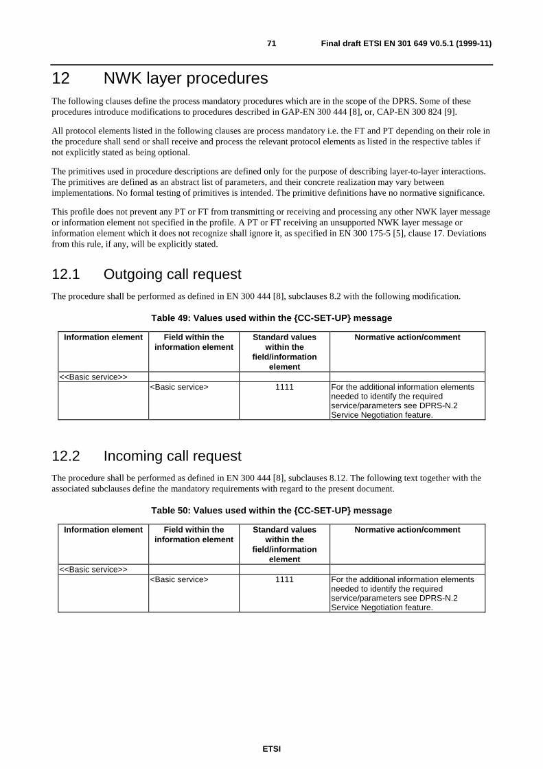
ETSI
Final draft ETSI EN 301 649 V0.5.1 (1999-11)71
12 NWK layer proceduresThe following clauses define the process mandatory procedures which are in the scope of the DPRS. Some of theseprocedures introduce modifications to procedures described in GAP-EN 300 444 [8], or, CAP-EN 300 824 [9].
All protocol elements listed in the following clauses are process mandatory i.e. the FT and PT depending on their role inthe procedure shall send or shall receive and process the relevant protocol elements as listed in the respective tables ifnot explicitly stated as being optional.
The primitives used in procedure descriptions are defined only for the purpose of describing layer-to-layer interactions.The primitives are defined as an abstract list of parameters, and their concrete realization may vary betweenimplementations. No formal testing of primitives is intended. The primitive definitions have no normative significance.
This profile does not prevent any PT or FT from transmitting or receiving and processing any other NWK layer messageor information element not specified in the profile. A PT or FT receiving an unsupported NWK layer message orinformation element which it does not recognize shall ignore it, as specified in EN 300 175-5 [5], clause 17. Deviationsfrom this rule, if any, will be explicitly stated.
12.1 Outgoing call requestThe procedure shall be performed as defined in EN 300 444 [8], subclauses 8.2 with the following modification.
Table 49: Values used within the {CC-SET-UP} message
Information element Field within theinformation element
Standard valueswithin the
field/informationelement
Normative action/comment
<<Basic service>><Basic service> 1111 For the additional information elements
needed to identify the requiredservice/parameters see DPRS-N.2Service Negotiation feature.
12.2 Incoming call requestThe procedure shall be performed as defined in EN 300 444 [8], subclauses 8.12. The following text together with theassociated subclauses define the mandatory requirements with regard to the present document.
Table 50: Values used within the {CC-SET-UP} message
Information element Field within theinformation element
Standard valueswithin the
field/informationelement
Normative action/comment
<<Basic service>><Basic service> 1111 For the additional information elements
needed to identify the requiredservice/parameters see DPRS-N.2Service Negotiation feature.
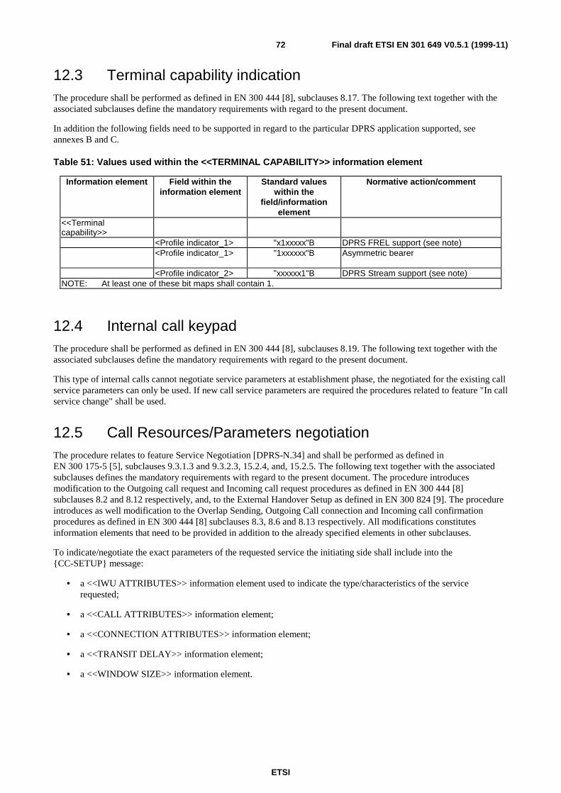
ETSI
Final draft ETSI EN 301 649 V0.5.1 (1999-11)72
12.3 Terminal capability indicationThe procedure shall be performed as defined in EN 300 444 [8], subclauses 8.17. The following text together with theassociated subclauses define the mandatory requirements with regard to the present document.
In addition the following fields need to be supported in regard to the particular DPRS application supported, seeannexes B and C.
Table 51: Values used within the <<TERMINAL CAPABILITY>> information element
Information element Field within theinformation element
Standard valueswithin the
field/informationelement
Normative action/comment
<<Terminalcapability>>
<Profile indicator_1> "x1xxxxx"B DPRS FREL support (see note)<Profile indicator_1> "1xxxxxx"B Asymmetric bearer
<Profile indicator_2> "xxxxxx1"B DPRS Stream support (see note)NOTE: At least one of these bit maps shall contain 1.
12.4 Internal call keypadThe procedure shall be performed as defined in EN 300 444 [8], subclauses 8.19. The following text together with theassociated subclauses define the mandatory requirements with regard to the present document.
This type of internal calls cannot negotiate service parameters at establishment phase, the negotiated for the existing callservice parameters can only be used. If new call service parameters are required the procedures related to feature "In callservice change" shall be used.
12.5 Call Resources/Parameters negotiationThe procedure relates to feature Service Negotiation [DPRS-N.34] and shall be performed as defined inEN 300 175-5 [5], subclauses 9.3.1.3 and 9.3.2.3, 15.2.4, and, 15.2.5. The following text together with the associatedsubclauses defines the mandatory requirements with regard to the present document. The procedure introducesmodification to the Outgoing call request and Incoming call request procedures as defined in EN 300 444 [8]subclauses 8.2 and 8.12 respectively, and, to the External Handover Setup as defined in EN 300 824 [9]. The procedureintroduces as well modification to the Overlap Sending, Outgoing Call connection and Incoming call confirmationprocedures as defined in EN 300 444 [8] subclauses 8.3, 8.6 and 8.13 respectively. All modifications constitutesinformation elements that need to be provided in addition to the already specified elements in other subclauses.
To indicate/negotiate the exact parameters of the requested service the initiating side shall include into the{CC-SETUP} message:
• a <<IWU ATTRIBUTES>> information element used to indicate the type/characteristics of the servicerequested;
• a <<CALL ATTRIBUTES>> information element;
• a <<CONNECTION ATTRIBUTES>> information element;
• a <<TRANSIT DELAY>> information element;
• a <<WINDOW SIZE>> information element.
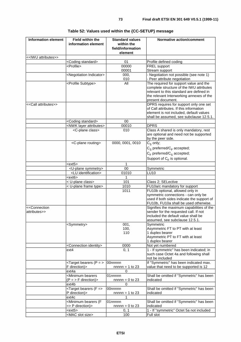
ETSI
Final draft ETSI EN 301 649 V0.5.1 (1999-11)73
Table 52: Values used within the {CC-SETUP} message
Information element Field within theinformation element
Standard valueswithin the
field/informationelement
Normative action/comment
<<IWU attributes>><Coding standard> 01 Profile defined coding<Profile> 00000
00001FREL supportStream support
<Negotiation Indicator> 000,010
- Negotiation not possible (see note 1)- Peer attribute negotiation
<Profile Subtype> All The required for support value and thecomplete structure of the IWU attributesrelevant to this standard are defined inthe relevant Interworking annexes of thepresent document.
<<Call attributes>> DPRS requires for support only one setof Call attributes. If this informationelement is not included, default valuesshall be assumed, see subclause 12.5.1.
<Coding standard> 00<NWK layer attributes> 00010 DPRS
<C-plane class> 010 Class A shared is only mandatory, restare optional and need not be supportedby the peer side.
<C-plane routing> 0000, 0001, 0010 CS only;CS preferred/CF accepted;CF preferred/CS accepted;Support of CF is optional.
<ext5> 1<U-plane symmetry> 00 Symmetric<LU identification> 01010 LU10
<ext6> 1< U-plane class> 101 Class 2; SELective< U-plane frame type> 1010 FU10a/c mandatory for support
1011 FU10b optional, allowed only insymmetric connections - can only beused if both sides indicate the support ofFU10b, FU10a shall be used otherwise.
<<Connectionattributes>>
Signifies the maximum capabilities of thesender for the requested call. If notincluded the default value shall beassumed, see subclause 12.5.1.
<Symmetry> 001,100,110
SymmetricAsymmetric FT to PT with at least1 duplex bearerAsymmetric PT to FT with at least1 duplex bearer
<Connection identity> 0000 Not yet numberedext4 0, 1 1 - If symmetric" has been indicated; in
such case Octet 4a and following shallnot be included
<Target bearers (P = >F direction)>
00nnnnnnnnnn = 1 to 23
If "Symmetric" has been indicated max.value that need to be supported is 12
ext4a 0<Minimum bearers(P = > F direction)>
01nnnnnnnnnn = 0 to 23
Shall be omitted if "Symmetric" has beenindicated
ext4b 0<Target bearers (F =>P direction)>
00nnnnnnnnnn = 1 to 23
Shall be omitted if "Symmetric" has beenindicated
ext4c 1<Minimum bearers (F=> P direction)>
01nnnnnnnnnn = 0 to 23
Shall be omitted if "Symmetric" has beenindicated
<ext5> 0, 1 1 - If "symmetric" Octet 5a not included<MAC slot size> 100 Full slot

ETSI
Final draft ETSI EN 301 649 V0.5.1 (1999-11)74
Information element Field within theinformation element
Standard valueswithin the
field/informationelement
Normative action/comment
<MAC service P=>F > 0010,0011
IP; detect onlyIP; Mod-2 correctSupport of "IP; Mod-2 correct" is optional
<ext5a> 1<spare> 1000<MAC service F=>P> 0010,
0011IP; detect onlyIP; Mod-2 correctSupport of "IP; Mod-2 correct" is optional
<Ext6> 1, 0 1 - If "symmetric" Octet 6a not included<CF-channel attributesP=>F >
000,010
CF never (CS only)CF Demand/1 bearer (interrupting)Support of CF is optional.
<MAC packet life timeP=>F >
0 to 7 Values > 0 only for IP-error-correct
<Ext6a> 1<CF-channel attributesF = > P >
000,010(check all other
tables, if this value iscorrected)
CF never (CS only)CF Demand/1 bearer (interrupting)Support of CF is optional.
<MAC packet life time F= >P >
0 to 7 Values > 0 only for IP-error-correct
<<Transit delay>> For the default value in case it is notincluded see subclause 12.5.1.
< Forward Delay> 0All
Infinite - Mandatory for supportRest - optional
< Backward Delay> 0All
It is not required to support differentvalues in Backwards direction
<<Window size>> (see note 2)For the default values if not included seesubclause 12.5.1.
ext3 0<Window size value(forward)>
All The value shall be placed in both 3 and3a octets as defined in EN 300 175-5 [5],subclause 7.7.43, see annex D.3.Maximum allowed for this profilevalue = 256.(see note 3)
ext3a 1<Window size value(forward) continue>
All
ext4 0<Window size value(backward)>
All The value shall be placed in both 3 and3a octets as defined in EN 300 175-5 [5],subclause 7.7.43, see clause D.3.Maximum allowed for this profilevalue = 256.
ext4a 1<Window size value(backward) continue>
All
NOTE 1: This value may only be used if all other parameters have values equal to the default values, seesubclause 12.5.1.
NOTE 2: If octet 4 (i.e. 4, 4a, 4b) is omitted the values defined in Ocetet 3x apply for both directions.NOTE 3: The values introduced in 11.1.1 need to be respected in all window-size fields.
If the parameters as indicated in the {CC-SETUP} message are not acceptable and support of negotiation is indicated inthe <<IWU-ATTRIBUTES>> the receiving side shall attempt negotiation if different services are possible, otherwisethe call shall be rejected using the Abnormal call release procedure as defined in EN 300 444 [8], subclause 8.7.
ETSI
Final draft ETSI EN 301 649 V0.5.1 (1999-11)75
For negotiation of <<IWU-ATTRIBUTES>> and <<CONNECTION ATTRIBUTES>> the Peer attribute negotiationprocedure as defined in EN 300 175-5 [5], subclause 15.2.5, shall be used. For negotiation of the <<TRANSITDELAY>> and the <<WINDOW SIZE>> the Operating parameter negotiation procedure as defined inEN 300 175-5 [5], subclause 15.2.4 shall be used. The following text together with the associated subclauses define themandatory requirements with regard to the present document.
If some of the proposed services in the {CC-SETUP} message are not acceptable the peer entity shall continue the callset-up procedure by including one alternative service description returning the appropriate<<CONNECTION ATTRIBUTES>> and/or <<CALL ATTRIBUTES>> and/or <<IWU-ATTRIBUTES>> and/or<<WINDOW SIZE>> and/or <<TRANSIT DELAY>> elements in the first response message (i.e. {CC-SETUP-ACK}or {CC-CONNECT} for FT, {CC-ALERTING} for PT).
If one or more of the values are acceptable the receiving side shall return unmodified parameters as formal acceptance ofthese unmodified values.
In all cases, the peer side shall only return a value less than or equal to the initial offer, and the initiating side shouldnormally accept any reduced value, even if this value differs to the default values indicated in subclause 12.5.1. Inexceptional circumstances, where the reduced value gives an unacceptable grade of service, the initiating side mayrelease the call.
In the case of the < C-plane routing > of the <<CALL ATTRIBUTES>> the peer side may return any supported valuefrom the values indicated in table 53. The actual C class used shall be based on the requirement for mandatory supportof the CS and optionally of the CF.
The values of <Coding standard> and <Profile> in the <<IWU-ATTRIBUTES>> cannot and shall not be changed; ifthese values are unacceptable the receiving side shall reject the call.
The initiating entity shall indicate its acceptance of these new attributes by proceeding with the normal call set-upprocedures. If it cannot support the new attributes the call shall be released using the normal release procedures. Therelease procedure should be used for attempt for re-negotiation of new set of attributes and, the release reason "Partialrelease" should be included to request maintain of the link for the new call set-up attempt. In case the exchangedparameters during the release are still not acceptable for the initiating side, the initiating side should notify the user forthe failure of the call and should not immediately initiate a new attempt. If the parameters are acceptable, a new callshall be initiated. To avoid a deadlock the parameters agreed during the release shall be used and accepted.
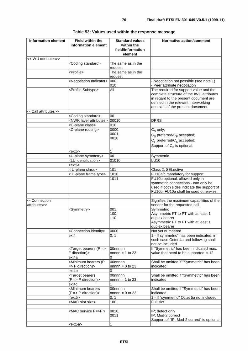
ETSI
Final draft ETSI EN 301 649 V0.5.1 (1999-11)76
Table 53: Values used within the response message
Information element Field within theinformation element
Standard valueswithin the
field/informationelement
Normative action/comment
<<IWU attributes>><Coding standard> The same as in the
request<Profile> The same as in the
request<Negotiation Indicator> 000,
010- Negotiation not possible (see note 1)- Peer attribute negotiation
<Profile Subtype> All The required for support value and thecomplete structure of the IWU attributesin regard to the present document aredefined in the relevant Interworkingannexes of the present document.
<<Call attributes>><Coding standard> 00<NWK layer attributes> 00010 DPRS<C-plane class> 010<C-plane routing> 0000,
0001,0010
CS only;CS preferred/CF accepted;CF preferred/CS accepted;Support of CF is optional.
<ext5> 1<U-plane symmetry> 00 Symmetric<LU identification> 01010 LU10<ext6> 1< U-plane class> 101 Class 2; SELective< U-plane frame type> 1010 FU10a/c mandatory for support
1011 FU10b optional, allowed only insymmetric connections - can only beused if both sides indicate the support ofFU10b, FU10a shall be used otherwise.
<<Connectionattributes>>
Signifies the maximum capabilities of thesender for the requested call
<Symmetry> 001,100,110
SymmetricAsymmetric FT to PT with at least 1duplex bearerAsymmetric PT to FT with at least 1duplex bearer
<Connection identity> 0000 Not yet numberedext4 0, 1 1 - If symmetric" has been indicated; in
such case Octet 4a and following shallnot be included
<Target bearers (P =>F direction)>
00nnnnnnnnnn = 1 to 23
If "Symmetric" has been indicated max.value that need to be supported is 12
ext4a 0<Minimum bearers (P=> F direction)>
00nnnnnnnnnn = 0 to 23
Shall be omitted if "Symmetric" has beenindicated
ext4b 0<Target bearers(F => P direction)>
00nnnnnnnnnn = 1 to 23
Shall be omitted if "Symmetric" has beenindicated
ext4c 1<Minimum bearers(F => P direction)>
00nnnnnnnnnn = 0 to 23
Shall be omitted if "Symmetric" has beenindicated
<ext5> 0, 1 1 - If "symmetric" Octet 5a not included<MAC slot size> 100 Full slot
<MAC service P=>F > 0010,0011
IP; detect onlyIP; Mod-2 correctSupport of "IP; Mod-2 correct" is optional
<ext5a> 1
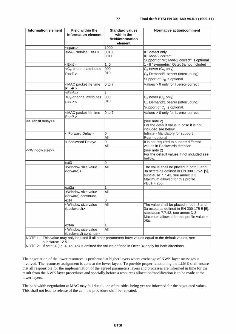
ETSI
Final draft ETSI EN 301 649 V0.5.1 (1999-11)77
Information element Field within theinformation element
Standard valueswithin the
field/informationelement
Normative action/comment
<spare> 1000<MAC service F=>P> 0010,
0011IP; detect onlyIP; Mod-2 correctSupport of "IP; Mod-2 correct" is optional
<Ext6> 1, 0 1 - If "symmetric" Octet 6a not included<CF-channel attributesP=>F >
000,010
CF never (CS only)CF Demand/1 bearer (interrupting)Support of CF is optional.
<MAC packet life timeP=>F >
0 to 7 Values > 0 only for IP-error-correct
<Ext6a> 1<CF-channel attributesF=>P >
000,010
CF never (CS only)CF Demand/1 bearer (interrupting)Support of CF is optional.
<MAC packet life timeF=>P >
0 to 7 Values > 0 only for IP-error-correct
<<Transit delay>> (see note 2)For the default value in case it is notincluded see below.
< Forward Delay> 0All
Infinite - Mandatory for supportRest - optional
< Backward Delay> 0All
It is not required to support differentvalues in Backwards direction
<<Window size>> (see note 2)For the default values if not included seebellow.
ext3 0<Window size value(forward)>
All The value shall be placed in both 3 and3a octets as defined in EN 300 175-5 [5],subclause 7.7.43, see annex D.3.Maximum allowed for this profilevalue = 256.
ext3a 1<Window size value(forward) continue>
All
ext4 0<Window size value(backward)>
All The value shall be placed in both 3 and3a octets as defined in EN 300 175-5 [5],subclause 7.7.43, see annex D.3.Maximum allowed for this profile value =256.
ext4a 1<Window size value(backward) continue>
All
NOTE 1: This value may only be used if all other parameters have values equal to the default values, seesubclause 12.5.1.
NOTE 2: If octet 4 (i.e. 4, 4a, 4b) is omitted the values defined in Octet 3x apply for both directions.
The negotiation of the lower resources is performed at higher layers where exchange of NWK layer messages isinvolved. The resources assignment is done at the lower layers. To provide proper functioning the LLME shall ensurethat all responsible for the implementation of the agreed parameters layers and processes are informed in time for theresult from the NWK layer procedures and specially before a resources allocation/modification is to be made at thelower layers.
The bandwidth negotiation at MAC may fail due to one of the sides being yet not informed for the negotiated values.This shall not lead to release of the call, the procedure shall be repeated.
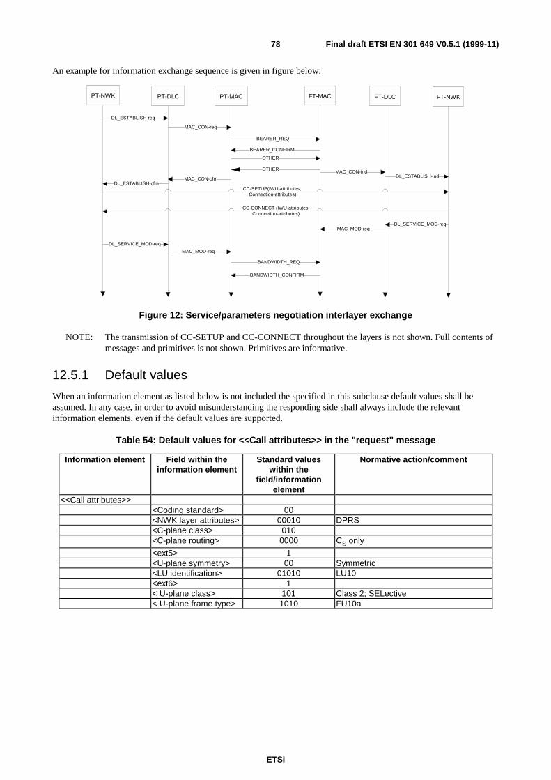
ETSI
Final draft ETSI EN 301 649 V0.5.1 (1999-11)78
An example for information exchange sequence is given in figure below:
PT-NWK PT-DLC PT-MAC FT-MAC FT-DLC FT-NWK
DL_ESTABLISH-req
DL_ESTABLISH-cfm
DL_ESTABLISH-ind
CC-SETUP(IWU-attributes,Connection-attributes)
CC-CONNECT (IWU-attributes,Conncetion-attributes)
MAC_CON-req
MAC_CON-cfm
MAC_CON-ind
BEARER_REQ
BEARER_CONFIRM
OTHER
OTHER
BANDWIDTH_REQ
BANDWIDTH_CONFIRM
DL_SERVICE_MOD-req
DL_SERVICE_MOD-req
MAC_MOD-req
MAC_MOD-req
Figure 12: Service/parameters negotiation interlayer exchange
NOTE: The transmission of CC-SETUP and CC-CONNECT throughout the layers is not shown. Full contents ofmessages and primitives is not shown. Primitives are informative.
12.5.1 Default values
When an information element as listed below is not included the specified in this subclause default values shall beassumed. In any case, in order to avoid misunderstanding the responding side shall always include the relevantinformation elements, even if the default values are supported.
Table 54: Default values for <<Call attributes>> in the "request" message
Information element Field within theinformation element
Standard valueswithin the
field/informationelement
Normative action/comment
<<Call attributes>><Coding standard> 00<NWK layer attributes> 00010 DPRS<C-plane class> 010<C-plane routing> 0000 CS only
<ext5> 1<U-plane symmetry> 00 Symmetric<LU identification> 01010 LU10<ext6> 1< U-plane class> 101 Class 2; SELective< U-plane frame type> 1010 FU10a
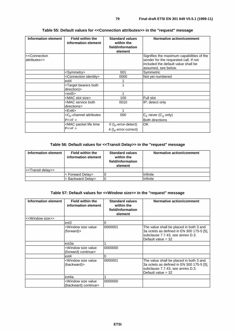
ETSI
Final draft ETSI EN 301 649 V0.5.1 (1999-11)79
Table 55: Default values for <<Connection attributes>> in the "request" message
Information element Field within theinformation element
Standard valueswithin the
field/informationelement
Normative action/comment
<<Connectionattributes>>
Signifies the maximum capabilities of thesender for the requested call. If notincluded the default value shall beassumed, see below.
<Symmetry> 001 Symmetric<Connection identity> 0000 Not yet numberedext4 1<Target bearers bothdirection)>
1
<ext5> 1<MAC slot size> 100 Full slot<MAC service bothdirections>
0010 IP; detect only
<Ext6> 1<CF-channel attributesP=>F >
000 CF never (CS only)Both directions
<MAC packet life timeP=>F >
0 (IP-error-detect)4 (IP-error-correct)
OK
Table 56: Default values for <<Transit Delay>> in the "request" message
Information element Field within theinformation element
Standard valueswithin the
field/informationelement
Normative action/comment
<<Transit delay>>< Forward Delay> 0 Infinite< Backward Delay> 0 Infinite
Table 57: Default values for <<Window size>> in the "request" message
Information element Field within theinformation element
Standard valueswithin the
field/informationelement
Normative action/comment
<<Window size>>ext3 0<Window size value(forward)>
0000001 The value shall be placed in both 3 and3a octets as defined in EN 300 175-5 [5],subclause 7.7.43, see annex D.3.Default value = 32
ext3a 1<Window size value(forward) continue>
0000000
ext4 0<Window size value(backward)>
0000001 The value shall be placed in both 3 and3a octets as defined in EN 300 175-5 [5],subclause 7.7.43, see annex D.3.Default value = 32
ext4a 1<Window size value(backward) continue>
0000000
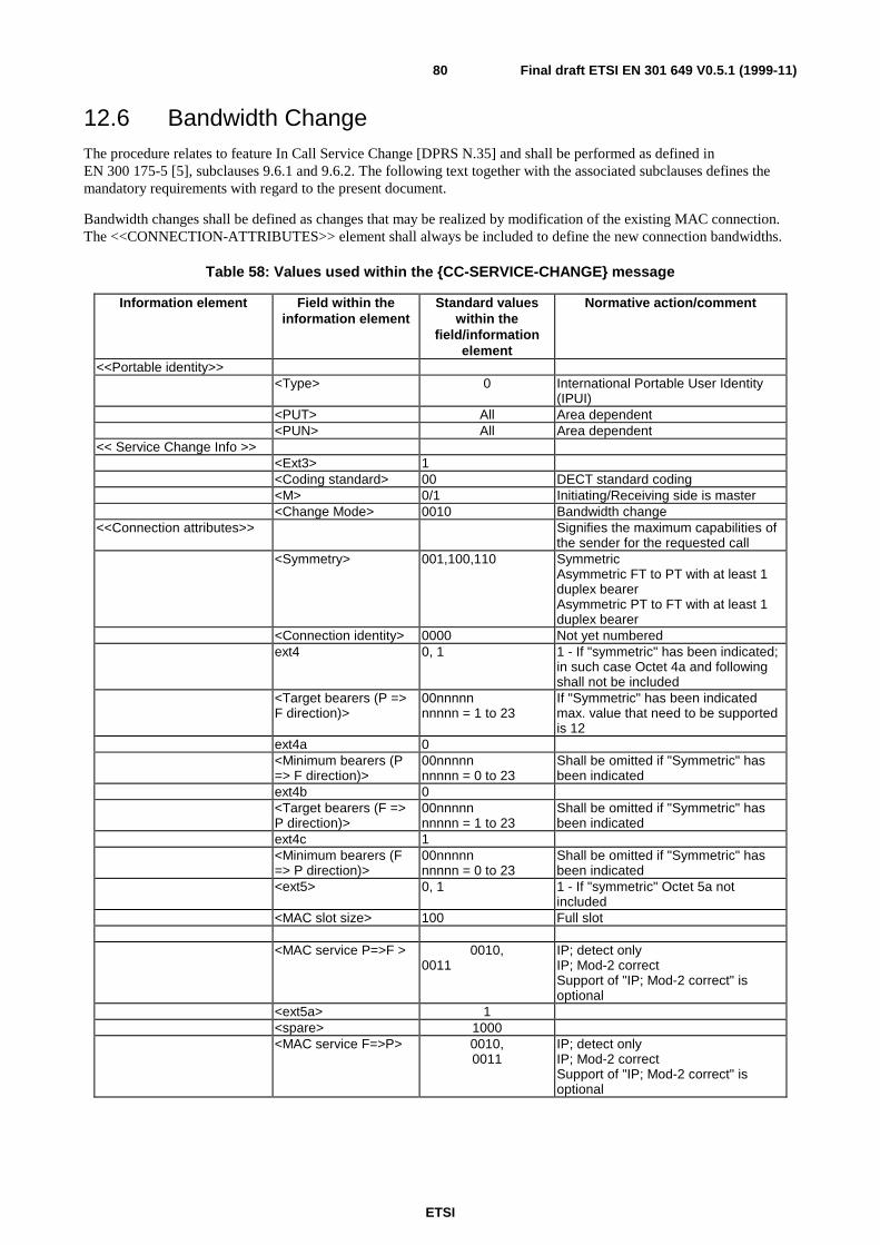
ETSI
Final draft ETSI EN 301 649 V0.5.1 (1999-11)80
12.6 Bandwidth ChangeThe procedure relates to feature In Call Service Change [DPRS N.35] and shall be performed as defined inEN 300 175-5 [5], subclauses 9.6.1 and 9.6.2. The following text together with the associated subclauses defines themandatory requirements with regard to the present document.
Bandwidth changes shall be defined as changes that may be realized by modification of the existing MAC connection.The <<CONNECTION-ATTRIBUTES>> element shall always be included to define the new connection bandwidths.
Table 58: Values used within the {CC-SERVICE-CHANGE} message
Information element Field within theinformation element
Standard valueswithin the
field/informationelement
Normative action/comment
<<Portable identity>><Type> 0 International Portable User Identity
(IPUI)<PUT> All Area dependent<PUN> All Area dependent
<< Service Change Info >><Ext3> 1<Coding standard> 00 DECT standard coding<M> 0/1 Initiating/Receiving side is master<Change Mode> 0010 Bandwidth change
<<Connection attributes>> Signifies the maximum capabilities ofthe sender for the requested call
<Symmetry> 001,100,110 SymmetricAsymmetric FT to PT with at least 1duplex bearerAsymmetric PT to FT with at least 1duplex bearer
<Connection identity> 0000 Not yet numberedext4 0, 1 1 - If "symmetric" has been indicated;
in such case Octet 4a and followingshall not be included
<Target bearers (P =>F direction)>
00nnnnnnnnnn = 1 to 23
If "Symmetric" has been indicatedmax. value that need to be supportedis 12
ext4a 0<Minimum bearers (P=> F direction)>
00nnnnnnnnnn = 0 to 23
Shall be omitted if "Symmetric" hasbeen indicated
ext4b 0<Target bearers (F =>P direction)>
00nnnnnnnnnn = 1 to 23
Shall be omitted if "Symmetric" hasbeen indicated
ext4c 1<Minimum bearers (F=> P direction)>
00nnnnnnnnnn = 0 to 23
Shall be omitted if "Symmetric" hasbeen indicated
<ext5> 0, 1 1 - If "symmetric" Octet 5a notincluded
<MAC slot size> 100 Full slot
<MAC service P=>F > 0010,0011
IP; detect onlyIP; Mod-2 correctSupport of "IP; Mod-2 correct" isoptional
<ext5a> 1<spare> 1000<MAC service F=>P> 0010,
0011IP; detect onlyIP; Mod-2 correctSupport of "IP; Mod-2 correct" isoptional

ETSI
Final draft ETSI EN 301 649 V0.5.1 (1999-11)81
Information element Field within theinformation element
Standard valueswithin the
field/informationelement
Normative action/comment
<Ext6> 1, 0 1 - If "symmetric" Octet 6a notincluded
<CF-channel attributesP=>F >
000,010
CF never (CS only)CF Demand/1 bearer (interrupting)Support of CF is optional.
<MAC packet life timeP=>F >
0 to 7 values >0 only for IP_error_correct
<Ext6a> 1<CF-channel attributesF=>P >
000,010
CF never (CS only)CF Demand/1 bearer (interrupting)Support of CF is optional.
<MAC packet life timeF=>P >
0 to 7 values >0 only for IP_error_correct
Table 59: Values used within the {CC-SERVICE-ACCEPT} message
Information element Field within theinformation element
Standard valueswithin the
field/informationelement
Normative action/comment
All optional - The receiving side is notallowed to suggest back different tothe requested settings
12.6.1 Associated procedures
12.6.1.1 Timer F/P <CC_service> management
<CC_service>: Service Change timer;
Value: 20 seconds
Start: {CC-SERVICE-CHANGE} message is sent;
Stop: An indication for link release from the DLC is received; A {CC-SERVICE-ACCEPT} or a{CC-SERVICE-REJECT} message is received; {CC-RELEASE}, {CC-RELEASE-COM}messages are sent or received.
12.6.2 Exceptional cases
12.6.2.1 Service change request is rejected
If the receiving side is not able to handle the requested service change it shall reject it.
Table 60: Values used within the {CC-SERVICE-REJECT} message
Information element Field within theinformation element
Standard valueswithin the
field/informationelement
Normative action/comment
All optional
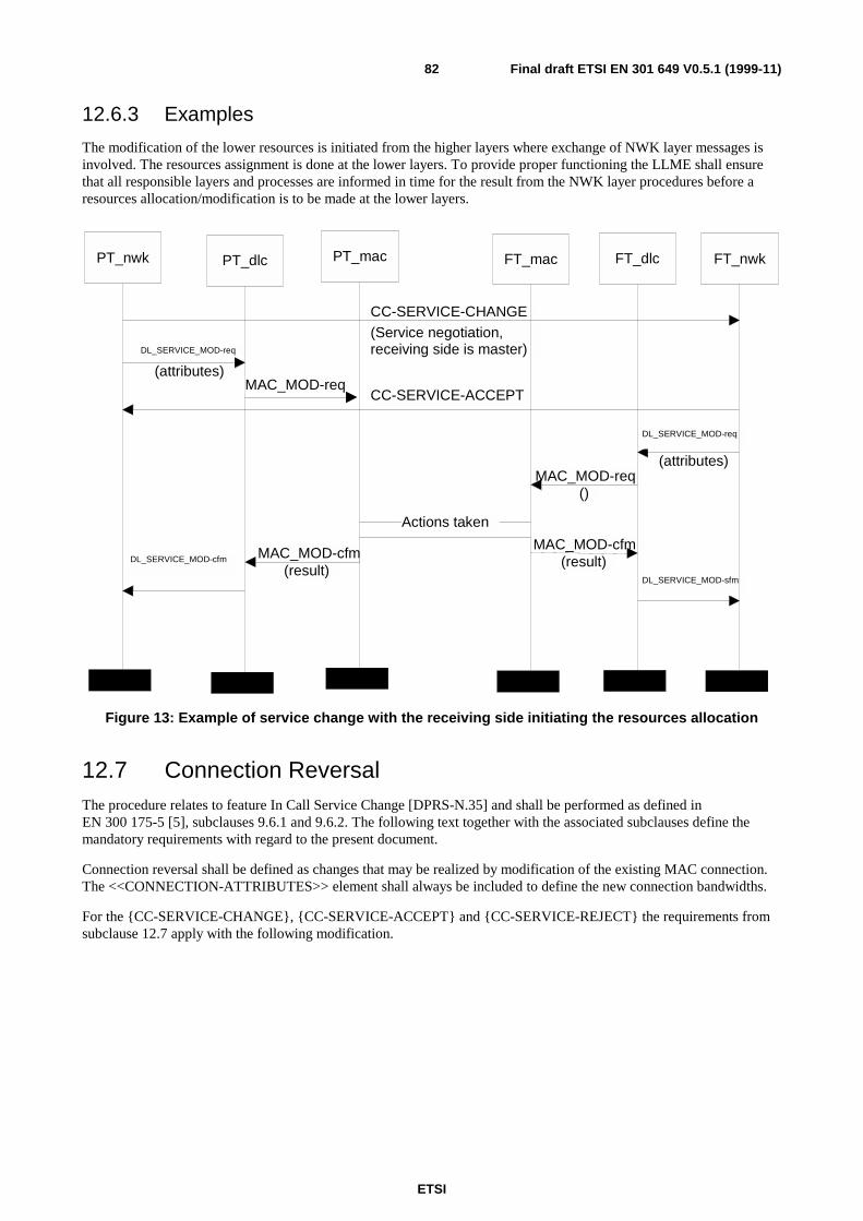
ETSI
Final draft ETSI EN 301 649 V0.5.1 (1999-11)82
12.6.3 Examples
The modification of the lower resources is initiated from the higher layers where exchange of NWK layer messages isinvolved. The resources assignment is done at the lower layers. To provide proper functioning the LLME shall ensurethat all responsible layers and processes are informed in time for the result from the NWK layer procedures before aresources allocation/modification is to be made at the lower layers.
DL_SERVICE_MOD-req
(attributes)
(attributes)
CC-SERVICE-ACCEPT
CC-SERVICE-CHANGE(Service negotiation,receiving side is master)
MAC_MOD-cfm(result)
MAC_MOD-cfm(result)
MAC_MOD-req()
PT_nwk PT_dlc PT_mac FT_mac FT_dlc FT_nwk
Actions taken
DL_SERVICE_MOD-req
DL_SERVICE_MOD-cfm
DL_SERVICE_MOD-sfm
MAC_MOD-req
Figure 13: Example of service change with the receiving side initiating the resources allocation
12.7 Connection ReversalThe procedure relates to feature In Call Service Change [DPRS-N.35] and shall be performed as defined inEN 300 175-5 [5], subclauses 9.6.1 and 9.6.2. The following text together with the associated subclauses define themandatory requirements with regard to the present document.
Connection reversal shall be defined as changes that may be realized by modification of the existing MAC connection.The <<CONNECTION-ATTRIBUTES>> element shall always be included to define the new connection bandwidths.
For the {CC-SERVICE-CHANGE}, {CC-SERVICE-ACCEPT} and {CC-SERVICE-REJECT} the requirements fromsubclause 12.7 apply with the following modification.
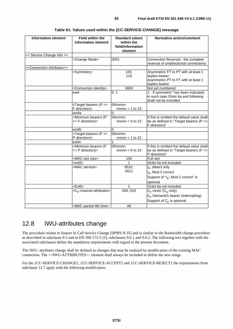
ETSI
Final draft ETSI EN 301 649 V0.5.1 (1999-11)83
Table 61: Values used within the {CC-SERVICE-CHANGE} message
Information element Field within theinformation element
Standard valueswithin the
field/informationelement
Normative action/comment
<< Service Change Info >><Change Mode> 0001 Connection Reversal - the complete
reversal of unidirectional connections<<Connection Attributes>>
<Symmetry> 100,110
Asymmetric FT to PT with at least 1duplex bearerAsymmetric PT to FT with at least 1duplex bearer
<Connection identity> 0000 Not yet numberedext4 0, 1 1 - If symmetric" has been indicated;
in such case Octet 4a and followingshall not be included
<Target bearers (P =>F direction)>
00nnnnnnnnnn = 1 to 23
ext4a 0<Minimum bearers (P=> F direction)>
00nnnnnnnnnn = 0 to 23
If this is omitted the default value shallbe as defined in "Target bearers (P =>F direction)"
ext4b 0<Target bearers (F =>P direction)>
00nnnnnnnnnn = 1 to 23
ext4c 1<Minimum bearers (F=> P direction)>
00nnnnnnnnnn = 0 to 23
If this is omitted the default value shallbe as defined in "Target bearers (F =>P direction)"
<MAC slot size> 100 Full slot<ext5> 1 Octet 5a not included<MAC service> 0010,
0011IP; detect onlyIP; Mod-2 correctSupport of "IP; Mod-2 correct" isoptional
<Ext6> 1 Octet 6a not included<CF-channel attributes> 000, 010 CF never (CS only)
CF Demand/1 bearer (interrupting)Support of CF is optional
<MAC packet life time> All
12.8 IWU-attributes changeThe procedure relates to feature In Call Service Change [DPRS-N.35] and is similar to the Bandwidth change procedureas described in subclause 8.3 and in EN 300 175-5 [5], subclauses 9.6.1 and 9.6.2. The following text together with theassociated subclauses define the mandatory requirements with regard to the present document.
The IWU- attributes change shall be defined as changes that may be realized by modification of the existing MACconnection. The <<IWU-ATTRIBUTES>> element shall always be included to define the new stings.
For the {CC-SERVICE-CHANGE}, {CC-SERVICE-ACCEPT} and {CC-SERVICE-REJECT} the requirements fromsubclause 12.7 apply with the following modification.
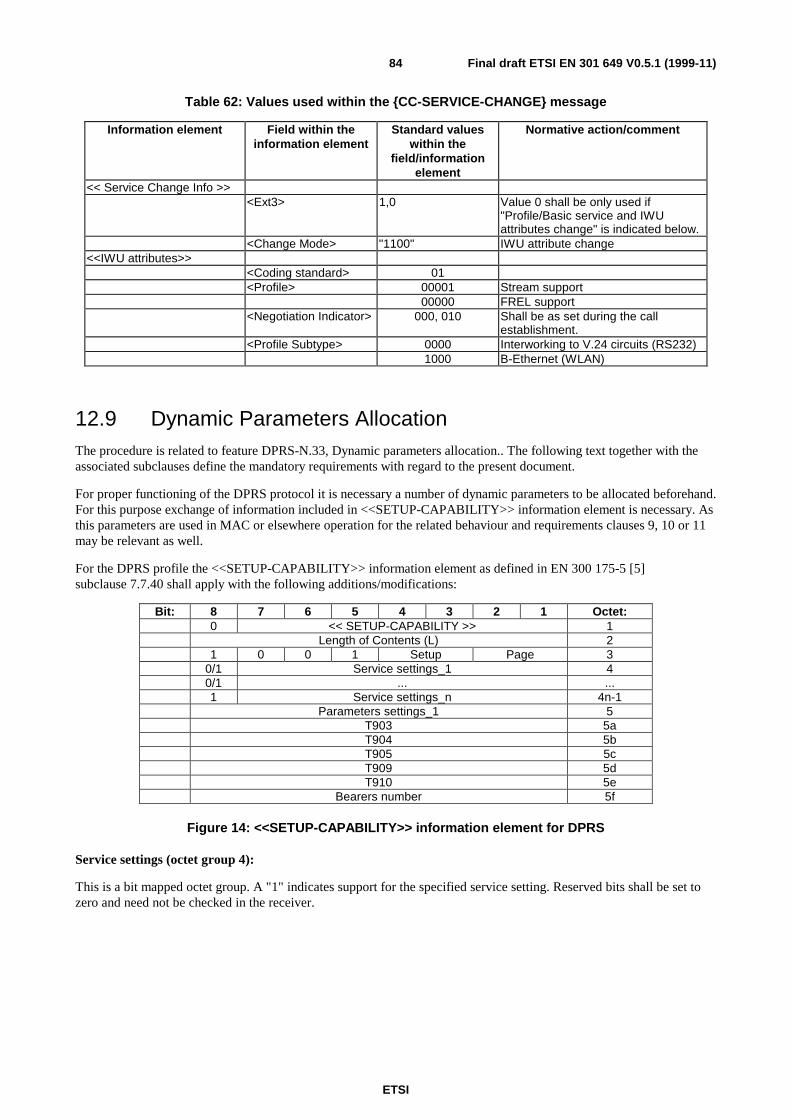
ETSI
Final draft ETSI EN 301 649 V0.5.1 (1999-11)84
Table 62: Values used within the {CC-SERVICE-CHANGE} message
Information element Field within theinformation element
Standard valueswithin the
field/informationelement
Normative action/comment
<< Service Change Info >><Ext3> 1,0 Value 0 shall be only used if
"Profile/Basic service and IWUattributes change" is indicated below.
<Change Mode> "1100" IWU attribute change<<IWU attributes>>
<Coding standard> 01<Profile> 00001 Stream support
00000 FREL support<Negotiation Indicator> 000, 010 Shall be as set during the call
establishment.<Profile Subtype> 0000 Interworking to V.24 circuits (RS232)
1000 B-Ethernet (WLAN)
12.9 Dynamic Parameters AllocationThe procedure is related to feature DPRS-N.33, Dynamic parameters allocation.. The following text together with theassociated subclauses define the mandatory requirements with regard to the present document.
For proper functioning of the DPRS protocol it is necessary a number of dynamic parameters to be allocated beforehand.For this purpose exchange of information included in <<SETUP-CAPABILITY>> information element is necessary. Asthis parameters are used in MAC or elsewhere operation for the related behaviour and requirements clauses 9, 10 or 11may be relevant as well.
For the DPRS profile the <<SETUP-CAPABILITY>> information element as defined in EN 300 175-5 [5]subclause 7.7.40 shall apply with the following additions/modifications:
Bit: 8 7 6 5 4 3 2 1 Octet:0 << SETUP-CAPABILITY >> 1
Length of Contents (L) 21 0 0 1 Setup Page 3
0/1 Service settings_1 40/1 ... ...1 Service settings_n 4n-1
Parameters settings_1 5T903 5aT904 5bT905 5cT909 5dT910 5e
Bearers number 5f
Figure 14: <<SETUP-CAPABILITY>> information element for DPRS
Service settings (octet group 4):
This is a bit mapped octet group. A "1" indicates support for the specified service setting. Reserved bits shall be set tozero and need not be checked in the receiver.
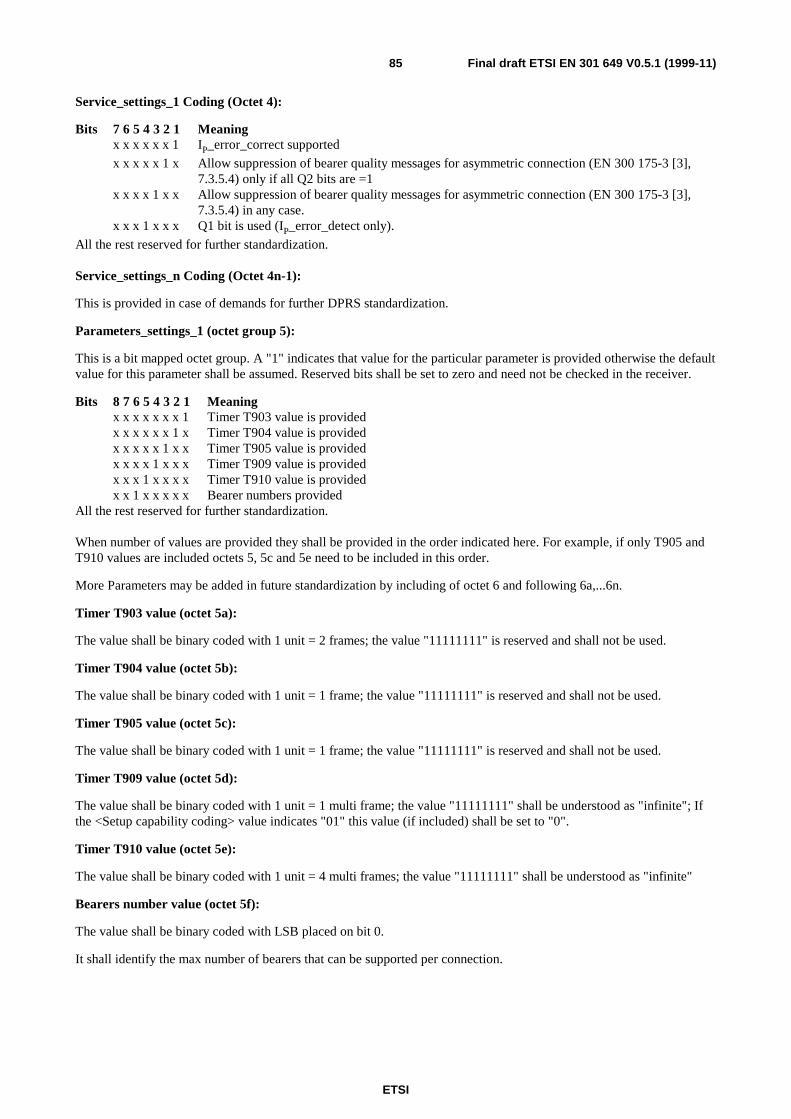
ETSI
Final draft ETSI EN 301 649 V0.5.1 (1999-11)85
Service_settings_1 Coding (Octet 4):
Bits 7 6 5 4 3 2 1 Meaningx x x x x x 1 IP_error_correct supported
x x x x x 1 x Allow suppression of bearer quality messages for asymmetric connection (EN 300 175-3 [3],7.3.5.4) only if all Q2 bits are =1
x x x x 1 x x Allow suppression of bearer quality messages for asymmetric connection (EN 300 175-3 [3],7.3.5.4) in any case.
x x x 1 x x x Q1 bit is used (IP_error_detect only).
All the rest reserved for further standardization.
Service_settings_n Coding (Octet 4n-1):
This is provided in case of demands for further DPRS standardization.
Parameters_settings_1 (octet group 5):
This is a bit mapped octet group. A "1" indicates that value for the particular parameter is provided otherwise the defaultvalue for this parameter shall be assumed. Reserved bits shall be set to zero and need not be checked in the receiver.
Bits 8 7 6 5 4 3 2 1 Meaningx x x x x x x 1 Timer T903 value is providedx x x x x x 1 x Timer T904 value is providedx x x x x 1 x x Timer T905 value is providedx x x x 1 x x x Timer T909 value is providedx x x 1 x x x x Timer T910 value is providedx x 1 x x x x x Bearer numbers provided
All the rest reserved for further standardization.
When number of values are provided they shall be provided in the order indicated here. For example, if only T905 andT910 values are included octets 5, 5c and 5e need to be included in this order.
More Parameters may be added in future standardization by including of octet 6 and following 6a,...6n.
Timer T903 value (octet 5a):
The value shall be binary coded with 1 unit = 2 frames; the value "11111111" is reserved and shall not be used.
Timer T904 value (octet 5b):
The value shall be binary coded with 1 unit = 1 frame; the value "11111111" is reserved and shall not be used.
Timer T905 value (octet 5c):
The value shall be binary coded with 1 unit = 1 frame; the value "11111111" is reserved and shall not be used.
Timer T909 value (octet 5d):
The value shall be binary coded with 1 unit = 1 multi frame; the value "11111111" shall be understood as "infinite"; Ifthe <Setup capability coding> value indicates "01" this value (if included) shall be set to "0".
Timer T910 value (octet 5e):
The value shall be binary coded with 1 unit = 4 multi frames; the value "11111111" shall be understood as "infinite"
Bearers number value (octet 5f):
The value shall be binary coded with LSB placed on bit 0.
It shall identify the max number of bearers that can be supported per connection.

ETSI
Final draft ETSI EN 301 649 V0.5.1 (1999-11)86
Table 63: Values used within the <<SETUP-CAPABILITY>> information element
Information element Field within theinformation element
Standard valueswithin the
field/informationelement
Normative action/comment
<<Set-up capability>><ext3> 0<Protocoldiscriminator>
001 DPRS
<Set-up> 01, 10 Setting and support depends on therelevant capability. Fast setup is optionalfor support.
<Page> 01, 10 Setting and support depends on therelevant capability. Fast paging isoptional for support.
<ext4> 1<Service_settings_1> 0000000 Default value - mandatory for support
xxxxxx1 IP_error_correct supported - optional forsupport
xxxxx1x Allow suppression of bearer qualitymessages for asymmetric connection(EN 300 175-3 [3], 7.3.5.4) only if all Q2bits are =1optional for support
xxxx1xx Allow suppression of bearer qualitymessages for asymmetric connection(EN 300 175-3 [3], 7.3.5.4) in any case.optional for support
xxx1xxx Q1 bit is used (IP_error_detect only).optional for support
<Parameter_settings_1>
As relevant If a bit is set to "0" the default values asindicated in A.1.3.1 and A.1.3.2 shall beassumed
T903 For the allowed valuessee A.1.3.1
If indicated in <Parameter_settings_1>that value for this is included(i.e. xxxxxxx1)
T904 For the allowed valuessee A.1.3.1
If indicated in <Parameter_settings_1>that value for this is included(i.e. xxxxxx1x)
T905 For the allowed valuessee A.1.3.1
If indicated in <Parameter_settings_1>that value for this is included(i.e. xxxxx1xx)
T909 For the allowed valuessee A.1.3.2
If indicated in <Parameter_settings_1>that value for this is included(i.e. xxxx1xxx)
T910 For the allowed valuessee A.1.3.1
If indicated in <Parameter_settings_1>that value for this is included(i.e. xxx1xxxx)
Bearer number 1 to 24
A PT shall include the <<SETUP-CAPABILITY>> information element in the {ACCESS-RIGHTS-REQUEST} and{LOCATE-REQUEST} messages.
A FT shall include the <<Set-up capability>> information element in the {ACCESS-RIGHTS-ACCEPT} and{LOCATE-ACCEPT} messages. I addition the FT may include the <<SETUP-CAPABILITY>> in a {MM-INFO-SUGGEST} message or in a {CLMS-FIXED} message.
Both sides are required to understand and react properly upon receipt of a <<SETUP-CAPABILITY>> informationelement as described in this subclause.
In regard to the service support indicated in the <service settings> both sides are allowed to use a particular setting onlyif both sides have indicated support of this service.

ETSI
Final draft ETSI EN 301 649 V0.5.1 (1999-11)87
In regard to the values indicated in the <Parameters settings> see subclauses A.1.3.1 and A.1.3.2. For the T910parameter the lower indicated value by either side shall be considered as the agreed value and used afterwards even ifthis is lower than the default value as indicated in subclause A.1.3.2. In all cases if a side does not provide setting for aparticular parameter the default values as indicated in subclauses A.1.3.1 and A.1.3.2 shall be assumed as beingindicated".
For the complete contents of {ACCESS-RIGHTS-REQUEST} and {ACCESS-RIGHTS-ACCEPT} the requirements ofEN 300 444 [8], subclause 8.30 shall apply.
For the complete contents of {LOCATE-REQUEST} and {LOCATE-ACCEPT} the requirements of EN 300 444 [8],subclause 8.28 shall apply.
For the transmission of the {MM-INFO-SUGGEST} message the Procedure for parameter retrieval initiated by the FTas specified in EN 300 175-5 [5], subclause 13.7 shall apply.
For the contents of {MM-INFO-SUGGEST} the following requirements apply:
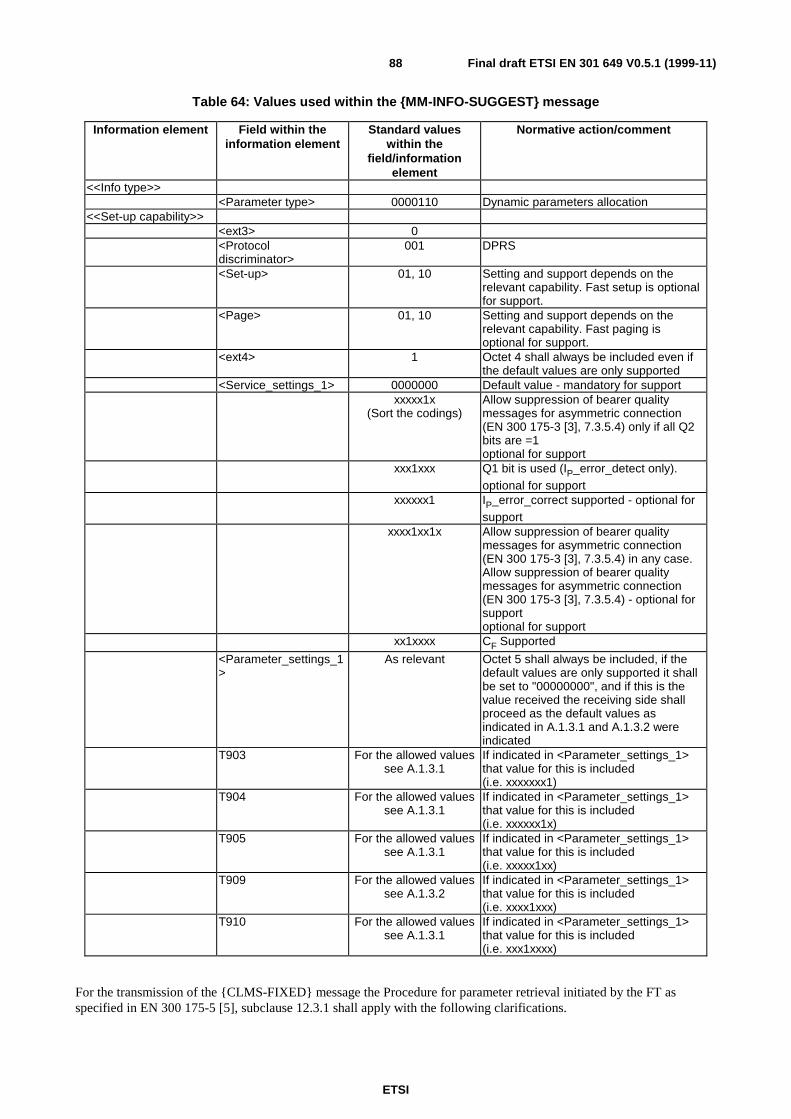
ETSI
Final draft ETSI EN 301 649 V0.5.1 (1999-11)88
Table 64: Values used within the {MM-INFO-SUGGEST} message
Information element Field within theinformation element
Standard valueswithin the
field/informationelement
Normative action/comment
<<Info type>><Parameter type> 0000110 Dynamic parameters allocation
<<Set-up capability>><ext3> 0<Protocoldiscriminator>
001 DPRS
<Set-up> 01, 10 Setting and support depends on therelevant capability. Fast setup is optionalfor support.
<Page> 01, 10 Setting and support depends on therelevant capability. Fast paging isoptional for support.
<ext4> 1 Octet 4 shall always be included even ifthe default values are only supported
<Service_settings_1> 0000000 Default value - mandatory for supportxxxxx1x
(Sort the codings)Allow suppression of bearer qualitymessages for asymmetric connection(EN 300 175-3 [3], 7.3.5.4) only if all Q2bits are =1optional for support
xxx1xxx Q1 bit is used (IP_error_detect only).optional for support
xxxxxx1 IP_error_correct supported - optional forsupport
xxxx1xx1x Allow suppression of bearer qualitymessages for asymmetric connection(EN 300 175-3 [3], 7.3.5.4) in any case.Allow suppression of bearer qualitymessages for asymmetric connection(EN 300 175-3 [3], 7.3.5.4) - optional forsupportoptional for support
xx1xxxx CF Supported
<Parameter_settings_1>
As relevant Octet 5 shall always be included, if thedefault values are only supported it shallbe set to "00000000", and if this is thevalue received the receiving side shallproceed as the default values asindicated in A.1.3.1 and A.1.3.2 wereindicated
T903 For the allowed valuessee A.1.3.1
If indicated in <Parameter_settings_1>that value for this is included(i.e. xxxxxxx1)
T904 For the allowed valuessee A.1.3.1
If indicated in <Parameter_settings_1>that value for this is included(i.e. xxxxxx1x)
T905 For the allowed valuessee A.1.3.1
If indicated in <Parameter_settings_1>that value for this is included(i.e. xxxxx1xx)
T909 For the allowed valuessee A.1.3.2
If indicated in <Parameter_settings_1>that value for this is included(i.e. xxxx1xxx)
T910 For the allowed valuessee A.1.3.1
If indicated in <Parameter_settings_1>that value for this is included(i.e. xxx1xxxx)
For the transmission of the {CLMS-FIXED} message the Procedure for parameter retrieval initiated by the FT asspecified in EN 300 175-5 [5], subclause 12.3.1 shall apply with the following clarifications.
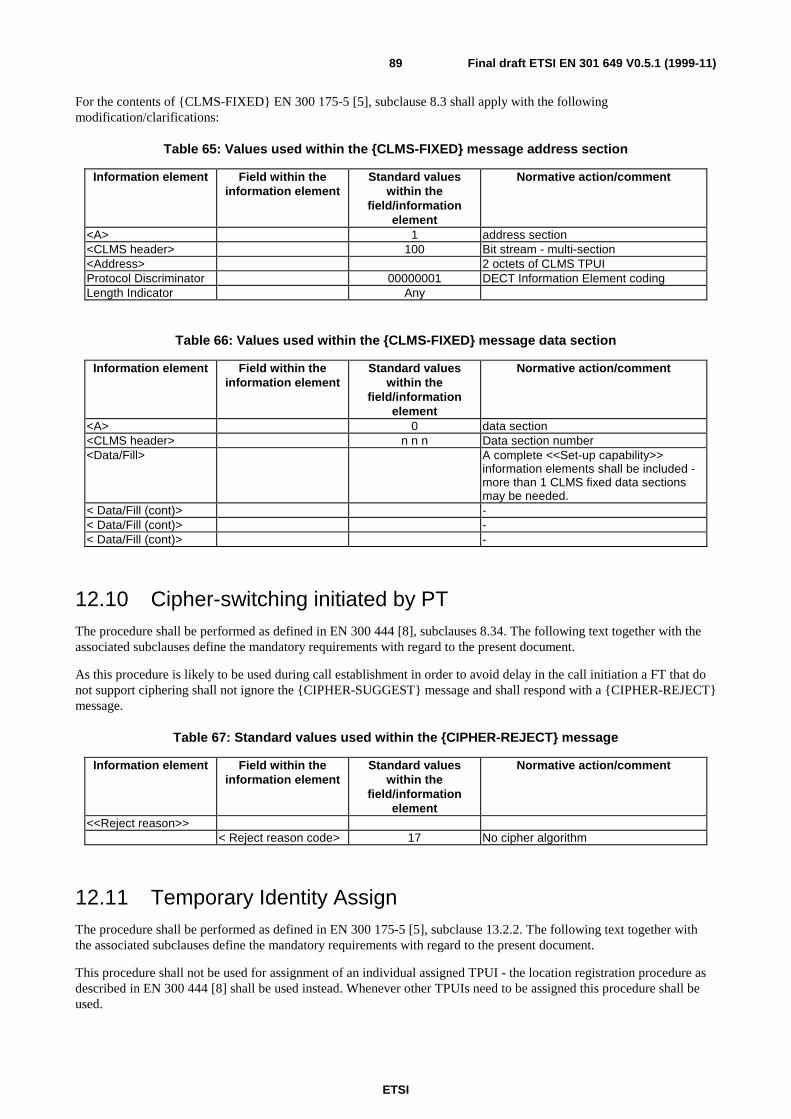
ETSI
Final draft ETSI EN 301 649 V0.5.1 (1999-11)89
For the contents of {CLMS-FIXED} EN 300 175-5 [5], subclause 8.3 shall apply with the followingmodification/clarifications:
Table 65: Values used within the {CLMS-FIXED} message address section
Information element Field within theinformation element
Standard valueswithin the
field/informationelement
Normative action/comment
<A> 1 address section<CLMS header> 100 Bit stream - multi-section<Address> 2 octets of CLMS TPUIProtocol Discriminator 00000001 DECT Information Element codingLength Indicator Any
Table 66: Values used within the {CLMS-FIXED} message data section
Information element Field within theinformation element
Standard valueswithin the
field/informationelement
Normative action/comment
<A> 0 data section<CLMS header> n n n Data section number<Data/Fill> A complete <<Set-up capability>>
information elements shall be included -more than 1 CLMS fixed data sectionsmay be needed.
< Data/Fill (cont)> -< Data/Fill (cont)> -< Data/Fill (cont)> -
12.10 Cipher-switching initiated by PTThe procedure shall be performed as defined in EN 300 444 [8], subclauses 8.34. The following text together with theassociated subclauses define the mandatory requirements with regard to the present document.
As this procedure is likely to be used during call establishment in order to avoid delay in the call initiation a FT that donot support ciphering shall not ignore the {CIPHER-SUGGEST} message and shall respond with a {CIPHER-REJECT}message.
Table 67: Standard values used within the {CIPHER-REJECT} message
Information element Field within theinformation element
Standard valueswithin the
field/informationelement
Normative action/comment
<<Reject reason>>< Reject reason code> 17 No cipher algorithm
12.11 Temporary Identity AssignThe procedure shall be performed as defined in EN 300 175-5 [5], subclause 13.2.2. The following text together withthe associated subclauses define the mandatory requirements with regard to the present document.
This procedure shall not be used for assignment of an individual assigned TPUI - the location registration procedure asdescribed in EN 300 444 [8] shall be used instead. Whenever other TPUIs need to be assigned this procedure shall beused.
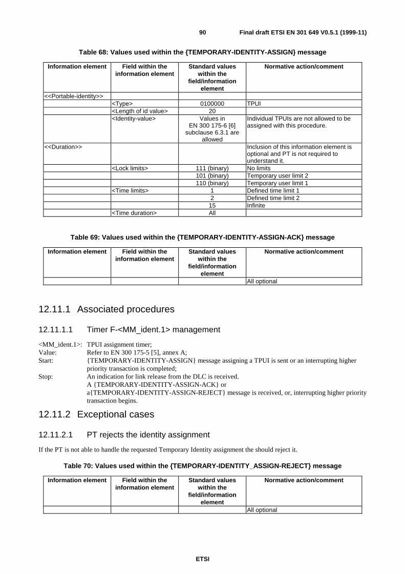
ETSI
Final draft ETSI EN 301 649 V0.5.1 (1999-11)90
Table 68: Values used within the {TEMPORARY-IDENTITY-ASSIGN} message
Information element Field within theinformation element
Standard valueswithin the
field/informationelement
Normative action/comment
<<Portable-identity>><Type> 0100000 TPUI<Length of id value> 20<Identity-value> Values in
EN 300 175-6 [6]subclause 6.3.1 are
allowed
Individual TPUIs are not allowed to beassigned with this procedure.
<<Duration>> Inclusion of this information element isoptional and PT is not required tounderstand it.
<Lock limits> 111 (binary) No limits101 (binary) Temporary user limit 2110 (binary) Temporary user limit 1
<Time limits> 1 Defined time limit 12 Defined time limit 2
15 Infinite<Time duration> All
Table 69: Values used within the {TEMPORARY-IDENTITY-ASSIGN-ACK} message
Information element Field within theinformation element
Standard valueswithin the
field/informationelement
Normative action/comment
All optional
12.11.1 Associated procedures
12.11.1.1 Timer F-<MM_ident.1> management
<MM_ident.1>: TPUI assignment timer;Value: Refer to EN 300 175-5 [5], annex A;Start: {TEMPORARY-IDENTITY-ASSIGN} message assigning a TPUI is sent or an interrupting higher
priority transaction is completed;Stop: An indication for link release from the DLC is received.
A {TEMPORARY-IDENTITY-ASSIGN-ACK} ora{TEMPORARY-IDENTITY-ASSIGN-REJECT} message is received, or, interrupting higher prioritytransaction begins.
12.11.2 Exceptional cases
12.11.2.1 PT rejects the identity assignment
If the PT is not able to handle the requested Temporary Identity assignment the should reject it.
Table 70: Values used within the {TEMPORARY-IDENTITY_ASSIGN-REJECT} message
Information element Field within theinformation element
Standard valueswithin the
field/informationelement
Normative action/comment
All optional
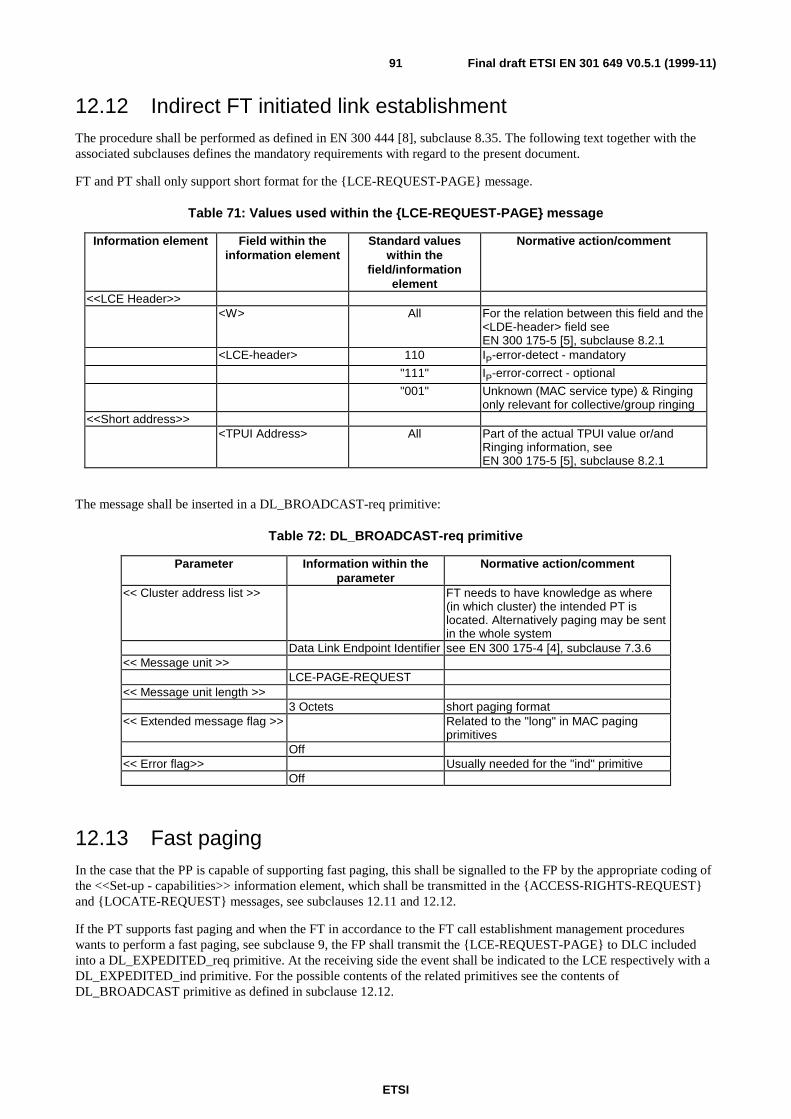
ETSI
Final draft ETSI EN 301 649 V0.5.1 (1999-11)91
12.12 Indirect FT initiated link establishmentThe procedure shall be performed as defined in EN 300 444 [8], subclause 8.35. The following text together with theassociated subclauses defines the mandatory requirements with regard to the present document.
FT and PT shall only support short format for the {LCE-REQUEST-PAGE} message.
Table 71: Values used within the {LCE-REQUEST-PAGE} message
Information element Field within theinformation element
Standard valueswithin the
field/informationelement
Normative action/comment
<<LCE Header>><W> All For the relation between this field and the
<LDE-header> field seeEN 300 175-5 [5], subclause 8.2.1
<LCE-header> 110 IP-error-detect - mandatory
"111" IP-error-correct - optional
"001" Unknown (MAC service type) & Ringingonly relevant for collective/group ringing
<<Short address>><TPUI Address> All Part of the actual TPUI value or/and
Ringing information, seeEN 300 175-5 [5], subclause 8.2.1
The message shall be inserted in a DL_BROADCAST-req primitive:
Table 72: DL_BROADCAST-req primitive
Parameter Information within theparameter
Normative action/comment
<< Cluster address list >> FT needs to have knowledge as where(in which cluster) the intended PT islocated. Alternatively paging may be sentin the whole system
Data Link Endpoint Identifier see EN 300 175-4 [4], subclause 7.3.6<< Message unit >>
LCE-PAGE-REQUEST<< Message unit length >>
3 Octets short paging format<< Extended message flag >> Related to the "long" in MAC paging
primitivesOff
<< Error flag>> Usually needed for the "ind" primitiveOff
12.13 Fast pagingIn the case that the PP is capable of supporting fast paging, this shall be signalled to the FP by the appropriate coding ofthe <<Set-up - capabilities>> information element, which shall be transmitted in the {ACCESS-RIGHTS-REQUEST}and {LOCATE-REQUEST} messages, see subclauses 12.11 and 12.12.
If the PT supports fast paging and when the FT in accordance to the FT call establishment management procedureswants to perform a fast paging, see subclause 9, the FP shall transmit the {LCE-REQUEST-PAGE} to DLC includedinto a DL_EXPEDITED_req primitive. At the receiving side the event shall be indicated to the LCE respectively with aDL_EXPEDITED_ind primitive. For the possible contents of the related primitives see the contents ofDL_BROADCAST primitive as defined in subclause 12.12.
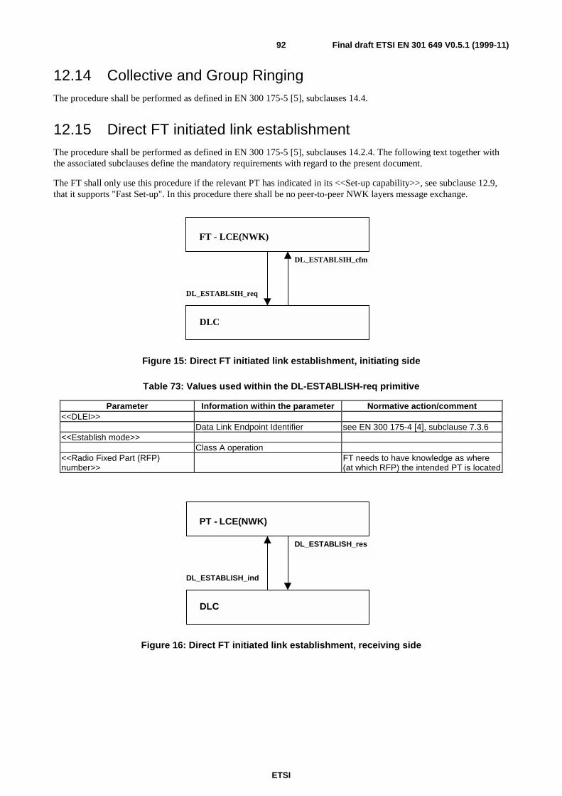
ETSI
Final draft ETSI EN 301 649 V0.5.1 (1999-11)92
12.14 Collective and Group RingingThe procedure shall be performed as defined in EN 300 175-5 [5], subclauses 14.4.
12.15 Direct FT initiated link establishmentThe procedure shall be performed as defined in EN 300 175-5 [5], subclauses 14.2.4. The following text together withthe associated subclauses define the mandatory requirements with regard to the present document.
The FT shall only use this procedure if the relevant PT has indicated in its <<Set-up capability>>, see subclause 12.9,that it supports "Fast Set-up". In this procedure there shall be no peer-to-peer NWK layers message exchange.
DL_ESTABLSIH_cfm
DL_ESTABLSIH_req
FT - LCE(NWK)
DLC
Figure 15: Direct FT initiated link establishment, initiating side
Table 73: Values used within the DL-ESTABLISH-req primitive
Parameter Information within the parameter Normative action/comment<<DLEI>>
Data Link Endpoint Identifier see EN 300 175-4 [4], subclause 7.3.6<<Establish mode>>
Class A operation<<Radio Fixed Part (RFP)number>>
FT needs to have knowledge as where(at which RFP) the intended PT is located
DL_ESTABLISH_res
DL_ESTABLISH_ind
PT - LCE(NWK)
DLC
Figure 16: Direct FT initiated link establishment, receiving side
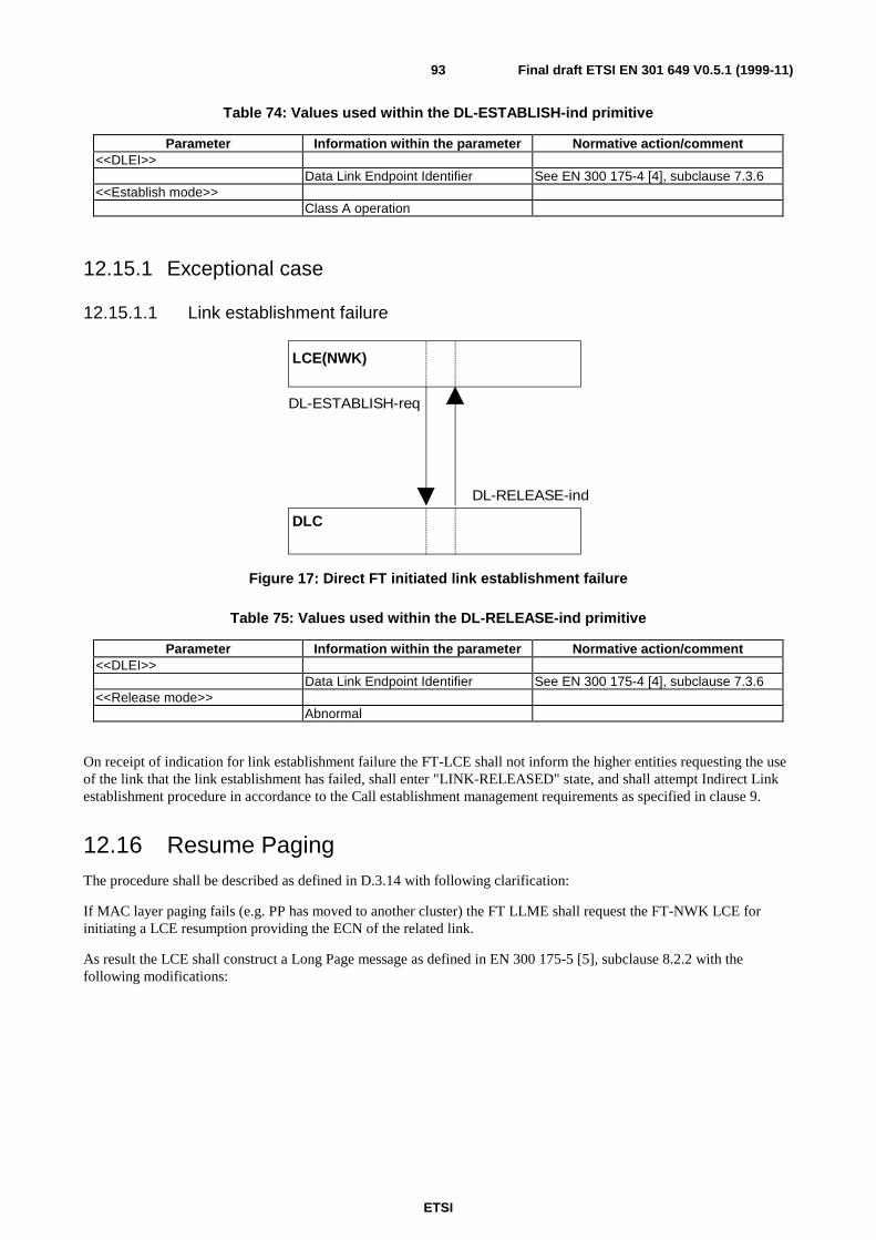
ETSI
Final draft ETSI EN 301 649 V0.5.1 (1999-11)93
Table 74: Values used within the DL-ESTABLISH-ind primitive
Parameter Information within the parameter Normative action/comment<<DLEI>>
Data Link Endpoint Identifier See EN 300 175-4 [4], subclause 7.3.6<<Establish mode>>
Class A operation
12.15.1 Exceptional case
12.15.1.1 Link establishment failure
LCE(NWK)
DLC
DL-RELEASE-ind
DL-ESTABLISH-req
Figure 17: Direct FT initiated link establishment failure
Table 75: Values used within the DL-RELEASE-ind primitive
Parameter Information within the parameter Normative action/comment<<DLEI>>
Data Link Endpoint Identifier See EN 300 175-4 [4], subclause 7.3.6<<Release mode>>
Abnormal
On receipt of indication for link establishment failure the FT-LCE shall not inform the higher entities requesting the useof the link that the link establishment has failed, shall enter "LINK-RELEASED" state, and shall attempt Indirect Linkestablishment procedure in accordance to the Call establishment management requirements as specified in clause 9.
12.16 Resume PagingThe procedure shall be described as defined in D.3.14 with following clarification:
If MAC layer paging fails (e.g. PP has moved to another cluster) the FT LLME shall request the FT-NWK LCE forinitiating a LCE resumption providing the ECN of the related link.
As result the LCE shall construct a Long Page message as defined in EN 300 175-5 [5], subclause 8.2.2 with thefollowing modifications:
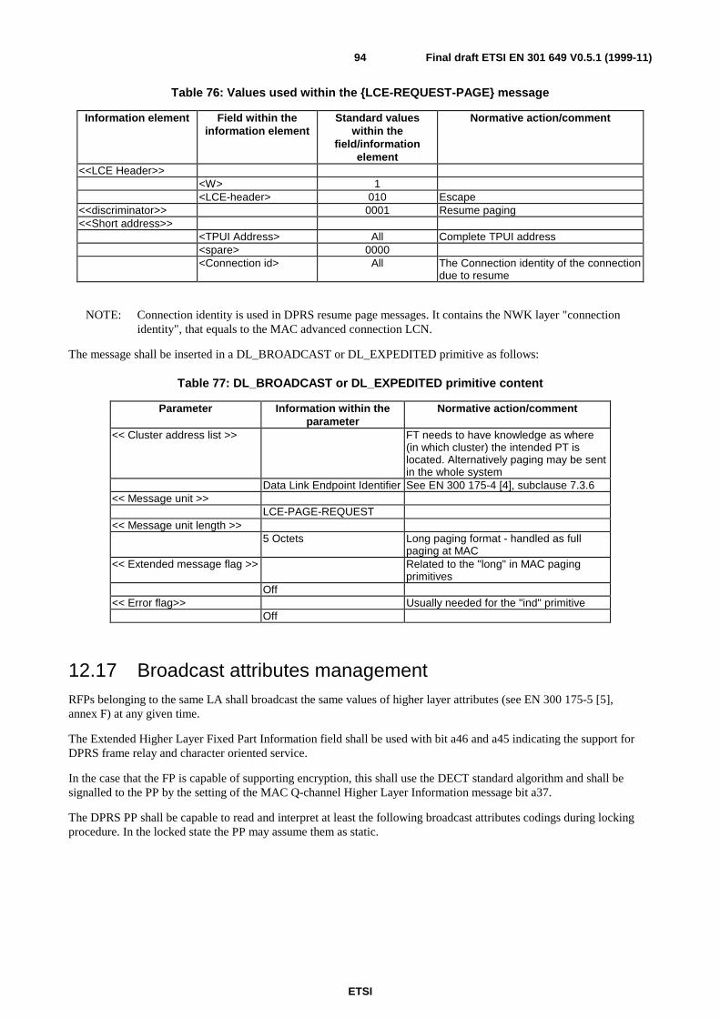
ETSI
Final draft ETSI EN 301 649 V0.5.1 (1999-11)94
Table 76: Values used within the {LCE-REQUEST-PAGE} message
Information element Field within theinformation element
Standard valueswithin the
field/informationelement
Normative action/comment
<<LCE Header>><W> 1<LCE-header> 010 Escape
<<discriminator>> 0001 Resume paging<<Short address>>
<TPUI Address> All Complete TPUI address<spare> 0000<Connection id> All The Connection identity of the connection
due to resume
NOTE: Connection identity is used in DPRS resume page messages. It contains the NWK layer "connectionidentity", that equals to the MAC advanced connection LCN.
The message shall be inserted in a DL_BROADCAST or DL_EXPEDITED primitive as follows:
Table 77: DL_BROADCAST or DL_EXPEDITED primitive content
Parameter Information within theparameter
Normative action/comment
<< Cluster address list >> FT needs to have knowledge as where(in which cluster) the intended PT islocated. Alternatively paging may be sentin the whole system
Data Link Endpoint Identifier See EN 300 175-4 [4], subclause 7.3.6<< Message unit >>
LCE-PAGE-REQUEST<< Message unit length >>
5 Octets Long paging format - handled as fullpaging at MAC
<< Extended message flag >> Related to the "long" in MAC pagingprimitives
Off<< Error flag>> Usually needed for the "ind" primitive
Off
12.17 Broadcast attributes managementRFPs belonging to the same LA shall broadcast the same values of higher layer attributes (see EN 300 175-5 [5],annex F) at any given time.
The Extended Higher Layer Fixed Part Information field shall be used with bit a46 and a45 indicating the support forDPRS frame relay and character oriented service.
In the case that the FP is capable of supporting encryption, this shall use the DECT standard algorithm and shall besignalled to the PP by the setting of the MAC Q-channel Higher Layer Information message bit a37.
The DPRS PP shall be capable to read and interpret at least the following broadcast attributes codings during lockingprocedure. In the locked state the PP may assume them as static.
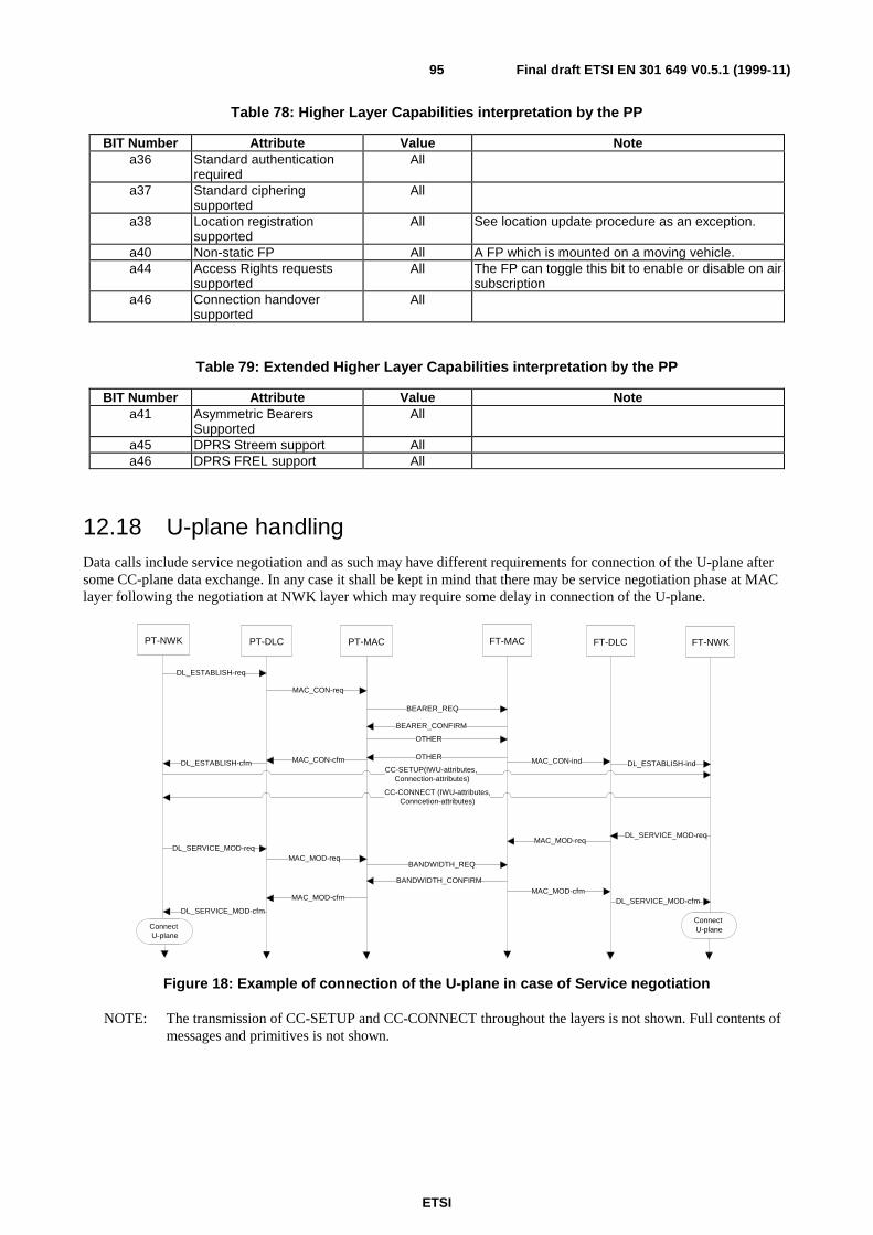
ETSI
Final draft ETSI EN 301 649 V0.5.1 (1999-11)95
Table 78: Higher Layer Capabilities interpretation by the PP
BIT Number Attribute Value Notea36 Standard authentication
requiredAll
a37 Standard cipheringsupported
All
a38 Location registrationsupported
All See location update procedure as an exception.
a40 Non-static FP All A FP which is mounted on a moving vehicle.a44 Access Rights requests
supportedAll The FP can toggle this bit to enable or disable on air
subscriptiona46 Connection handover
supportedAll
Table 79: Extended Higher Layer Capabilities interpretation by the PP
BIT Number Attribute Value Notea41 Asymmetric Bearers
SupportedAll
a45 DPRS Streem support Alla46 DPRS FREL support All
12.18 U-plane handlingData calls include service negotiation and as such may have different requirements for connection of the U-plane aftersome CC-plane data exchange. In any case it shall be kept in mind that there may be service negotiation phase at MAClayer following the negotiation at NWK layer which may require some delay in connection of the U-plane.
PT-NWK PT-DLC PT-MAC FT-MAC FT-DLC FT-NWK
DL_ESTABLISH-req
DL_ESTABLISH-cfm DL_ESTABLISH-indCC-SETUP(IWU-attributes,
Connection-attributes)
CC-CONNECT (IWU-attributes,Conncetion-attributes)
MAC_CON-req
MAC_CON-cfm MAC_CON-ind
BEARER_REQ
BEARER_CONFIRM
OTHER
OTHER
BANDWIDTH_REQ
BANDWIDTH_CONFIRM
DL_SERVICE_MOD-req
DL_SERVICE_MOD-req
MAC_MOD-req
MAC_MOD-req
MAC_MOD-cfm
DL_SERVICE_MOD-cfmDL_SERVICE_MOD-cfm
MAC_MOD-cfm
ConnectU-plane
ConnectU-plane
Figure 18: Example of connection of the U-plane in case of Service negotiation
NOTE: The transmission of CC-SETUP and CC-CONNECT throughout the layers is not shown. Full contents ofmessages and primitives is not shown.

ETSI
Final draft ETSI EN 301 649 V0.5.1 (1999-11)96
12.19 Management of MM proceduresThe procedure shall be performed as defined in EN 300 444 [8], subclauses 6.9.5 and 13.1. The following text togetherwith the associated subclauses define the mandatory requirements with regard to the present document.
The following table describes whether an MM procedure is supported in any CC state or whether a restriction applies.The restriction has been made in order to limit the complexity of the receiving side so that it is not mandated tounderstand MM messages in all CC states for the purpose of achieving inter-operability. This table shall be consideredin addition to the table included in EN 300 444 [8] subclause 6.9.5.
Table 80: Support of MM procedures in CC states
Procedure Mandatory support in CC stateDetach F(T)-00Temporary Identity Assign F(T)-00

ETSI
Final draft ETSI EN 301 649 V0.5.1 (1999-11)97
Annex A (normative):Operating parameters
A.1 ME operating parameters
A.1.1 Constants (applicable to class 1 and class 2 devices)
Table A.1: Timers T906 and T908
Timer Description value unitT906 Time that the real number of bearers have to be lower
that the "minimum number of bearers parameter inthe "MAC BANDWIDTH" command to consider it aviolation of bandwidth.
2 Seconds
T908 Timer that the PP or FP will wait after the unnoticedloss of all bearers received from other side to pass tosuspend sate
10 DECTFrames
A.1.2 Equations
A.1.2.1 Waiting time for collision avoidance (WtA)
Formula for waiting time after the end (transition 1->0) of RFP-busy-for data flag (EN 300 175-3 [3], 7.2.4.3.9) toprevent access collisions.
A.1.2.1.1 Description
If the RFP had activated the RFP-busy-for-data flag in RFP status (EN 300 175-3 [3], 7.2.4.3.9), after the deactivationof this flag, the PT shall wait a random interval WtA before initiating any bearer setup procedure, to prevent accesscollisions. In case of access collision during the following PT initiated setup procedure (subclause 10.5.1.1), the PTshall wait a random interval WtA before repeating the access request attempt. In case of successive collisions, formulawill be applied with successive increment in the spreading range
A.1.2.1.2 Formula
First time:
WtA (1) = Rn * T905
Successive attempts: 1<N≤6
WtA(N) = Rn * T905 * 2 N-1
Successive attempts N>6
WtA(N) = Rn * T905 * 2 5
Where N is the number of failures, and Rn is a pseudo-random number in the range 0 to 1, calculated by the PT.
A.1.2.2 Waiting time for congestion avoidance (WtB)
Formula for waiting time after a FP bandwidth refuse during a PT resume procedure or a bandwidth modificationrequest.

ETSI
Final draft ETSI EN 301 649 V0.5.1 (1999-11)98
A.1.2.2.1 Description
During a PT resume procedure if the FP responds indicating "bandwidth zero", the PT shall release the pilot bearer andwait an interval WtB before repeat the resume procedure. WtB is composed of a fixed part and a random componentidentical to WtA. In case of successive refusals, formula will be applied with successive increment in the spreadingrange.
Timer WtB shall be also applied when a PT requests a bandwidth modification that involves increasing the number ofbearers, and it is refused by the FT. In such a case, the PT shall not repeat the request of bandwidth extension during aninterval WtB.
NOTE: The PT may request bandwidth modification reducing number of bearers at any time.
A.1.2.2.2 Formula
First time:
WtB (1) = T904 + Rn * T905
Successive attempts: 1<N≤6
WtB(N) = T904 + Rn * T905 * 2 N-1
Successive attempts N>6
WtB(N) = T904 + Rn * T905 * 2 5
Where N is the number of failures, and Rn is a pseudo-random number in the range 0-1, calculated by the PT.
A.1.3 Variable parameters (class 2 systems only)
A.1.3.1 Parameters set by the FP (class 2 systems only)
Table A.2: Timers T903, T904, T905 and T910
Timer Description Unit Minimumvalue
Maximumvalue
Default value
T903 Maximum time that a PP could wait without transmittingnew upstream data or C-plane messages prior torelease the Physical Connection
2 DECTFrames=20ms
0 250(=500frames)
5(=10 frames)
T904 Fixed term of the waiting time that a PP should waitafter a FP refuse in a PP initiated Physical Connectionset up procedure.See equations subclause for formulae.
1 DECTFrame=10ms
0 31 10
T905 Random term of the waiting time that a PP should waitafter an access collision or a FP refuse in a PP initiatedPhysical Connection set up procedure.See equations subclause for formula.
1 DECTFrames=10ms
0 31 10
T910 Handshake procedure timer. A Virtual Call and itsassociated link and logical connection shall be releasedif after T910 there has not been any successfulhandshake between PT and FT.
4 DECTMF's=640ms
1 254+ infinitecoded 255(=1016 MF=162,56 s)
32(=128 MF's =20,48 s )
In class 2 systems, T903, T904, T905 and T910 are chosen by the FP and communicated to the PP's by means of the<<SETUP_CAPABILITY>> network layer information element. Any PP shall accept any value between minimum andmaximum range of the table.
In absence of Network layer communication of the parameter, the default value shall be used.

ETSI
Final draft ETSI EN 301 649 V0.5.1 (1999-11)99
A.1.3.2 Negotiable parameters between FP and PP (class 2 systems only)
Table A.3: Timer T909
Timer Description Unit Minimumvalue
Maximumvalue
Defaultvalue
T909 Fast set-up timer: Time in DECT Multiframes to keepthe receiver of the PP's in listening for fast set-up modeafter any Physical Connection suspend procedure.T909=0 means no fast set-up
1 DECTMF (=160 ms)
0 254+ infinitecoded 255.(40,64 s+infinite)
31(4,96 sec)
A.1.3.2.1 Conditions of negotiation
T909 is negotiable between FP and PP by means of the <<SETUP_CAPABILITY>> network layer information elementaccording to the following rules:
• If the PP declares to support fast setup in the setup capabilities bit, then it must accept 4,96 seconds of fast setuptimer. Upon this figure, the used value will be the minimum between FP and PP requested values;
• If the PP declares not to support fast setup in the setup capabilities bit, the value of T909 for the PP shall beequal to zero. The value of the network layer information element shall be ignored.
Any PP shall accept any value between and including 0 and 4,96 seconds for the fast setup timer.
A.2 Configuration capabilities for class 1 devicesIn order to assure reliable inter-working between devices complying with this profile in mobility class 1, it shall bepossible to install the following parameters in the FPs and/or PPs of the system. The values of parameters referring tothe PP shall be clearly indicated in the documentation of the PP, and means shall be provided in FPs for such values tobe registered. The values of parameters referring to the FP shall be clearly indicated in the documentation of the FP, andmeans shall be provided in PP for such values to be registered.
Table A.4: Configuration capabilities for class 1 devices
Parameter Value Configurable in: Fixed(F)/Portable(P)Service associated with identity Type A or B F, PData frames Selected from annex B F, PIPUI Unique value within local
environmentF
ARI Unique value within localenvironment
P
Maximum supported SDU size Number of octets F, PMulti-bearer capability 1 to 23 F, PAsymmetric capability Yes/No F, PDiversity capability Yes/No F, PFast paging available Yes/No F, PConnectionless downlink supported Yes/No F, PEncryption capability Yes/No F, PStatic cipher key 64 bits F, PT903 Resume timer 0 to 500 DECT Frames F, PT904 Wait timer. Fixed part 0 to 31 DECT Frames F, PT905 Wait timer. Random part 0 to 14 DECT Frames F, PT909 Setup detection timer 0 to 254 DECT
Multiframes +infiniteF, P
T910 Handshake procedure timer 0 to 1020 DECTMultiframes +infinite
F, P

ETSI
Final draft ETSI EN 301 649 V0.5.1 (1999-11)100
Annex B (normative):Interworking conventions for the Frame Relay (FREL)service
B.1 Scope of this annexThis annex defines the Interworking conventions for Frame Relay (FREL) service. DPRS Frame Relay Service may beused for the transport of the following protocols:
• ISO 8802-3 (Ethernet) [16];
• ISO 8802-5 (Token Ring) [17];
• Internet Protocol (IP) [18];
• Point to Point Protocol (PPP) [19].
Annexes B.1, B.2 and B.3 define a set of conventions applicable to the Frame Relay Service in general, and annexes B.4to B.7 define the specific conventions for each one of the transported protocols.
B.1.1 Typical configuration for the Frame Relay ServiceThe typical configuration for Frame Relay service is shown in the following figure:
Inter-WorkingFunction
PP FP/IWU Network
DECTU-planeFREL
C/L or C/OExternal
TransportNetwork
C/L ServiceProtocol
DECTC-plane
IWF
DECTC-plane
TAF
DECTU-planeFREL
C/L or C/OExternal
TransportNetwork
C/L ServiceProtocol
CUG
Mobility Class 2 Mobility Class 1
NOTE: STF: change "C/L service protocol" by "C/L or C/O service protocol" in this figure.
Figure B.1: Reference configuration for Frame Relay (FREL) Service,including interworking to connection-oriented or connectionless networks
Mobility class 2 equipment provides a full DECT C-plane, while for mobility class 1 equipment, the C-plane is replacedby a Closed User Group administration.
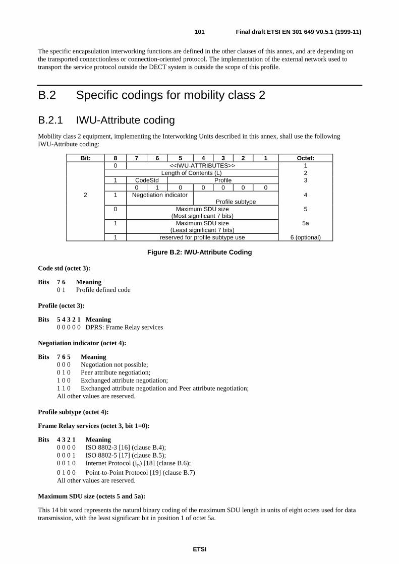
ETSI
Final draft ETSI EN 301 649 V0.5.1 (1999-11)101
The specific encapsulation interworking functions are defined in the other clauses of this annex, and are depending onthe transported connectionless or connection-oriented protocol. The implementation of the external network used totransport the service protocol outside the DECT system is outside the scope of this profile.
B.2 Specific codings for mobility class 2
B.2.1 IWU-Attribute codingMobility class 2 equipment, implementing the Interworking Units described in this annex, shall use the followingIWU-Attribute coding:
Bit: 8 7 6 5 4 3 2 1 Octet:0 <<IWU-ATTRIBUTES>> 1
Length of Contents (L) 21 CodeStd Profile 3
0 1 0 0 0 0 02 1 Negotiation indicator
Profile subtype4
0 Maximum SDU size(Most significant 7 bits)
5
1 Maximum SDU size(Least significant 7 bits)
5a
1 reserved for profile subtype use 6 (optional)
Figure B.2: IWU-Attribute Coding
Code std (octet 3):
Bits 7 6 Meaning0 1 Profile defined code
Profile (octet 3):
Bits 5 4 3 2 1 Meaning0 0 0 0 0 DPRS: Frame Relay services
Negotiation indicator (octet 4):
Bits 7 6 5 Meaning0 0 0 Negotiation not possible;0 1 0 Peer attribute negotiation;1 0 0 Exchanged attribute negotiation;1 1 0 Exchanged attribute negotiation and Peer attribute negotiation;All other values are reserved.
Profile subtype (octet 4):
Frame Relay services (octet 3, bit 1=0):
Bits 4 3 2 1 Meaning0 0 0 0 ISO 8802-3 [16] (clause B.4);0 0 0 1 ISO 8802-5 [17] (clause B.5);0 0 1 0 Internet Protocol (IP) [18] (clause B.6);
0 1 0 0 Point-to-Point Protocol [19] (clause B.7)All other values are reserved.
Maximum SDU size (octets 5 and 5a):
This 14 bit word represents the natural binary coding of the maximum SDU length in units of eight octets used for datatransmission, with the least significant bit in position 1 of octet 5a.
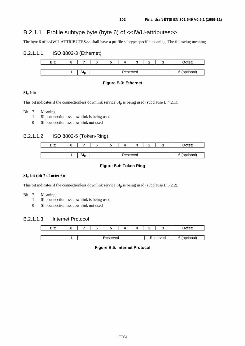
ETSI
Final draft ETSI EN 301 649 V0.5.1 (1999-11)102
B.2.1.1 Profile subtype byte (byte 6) of <<IWU-attributes>>
The byte 6 of <<IWU-ATTRIBUTES>> shall have a profile subtype specific meaning. The following meaning
B.2.1.1.1 ISO 8802-3 (Ethernet)
Bit: 8 7 6 5 4 3 2 1 Octet:
1 SIP Reserved 6 (optional)
Figure B.3: Ethernet
SIP bit:
This bit indicates if the connectionless downlink service SIP is being used (subclause B.4.2.1).
Bit 7 Meaning1 SIP connectionless downlink is being used
0 SIP connectionless downlink not used
B.2.1.1.2 ISO 8802-5 (Token-Ring)
Bit: 8 7 6 5 4 3 2 1 Octet:
1 SIP Reserved 6 (optional)
Figure B.4: Token Ring
SIP bit (bit 7 of octet 6):
This bit indicates if the connectionless downlink service SIP is being used (subclause B.5.2.2).
Bit 7 Meaning1 SIP connectionless downlink is being used
0 SIP connectionless downlink not used
B.2.1.1.3 Internet Protocol
Bit: 8 7 6 5 4 3 2 1 Octet:
1 Reserved Reserved 6 (optional)
Figure B.5: Internet Protocol
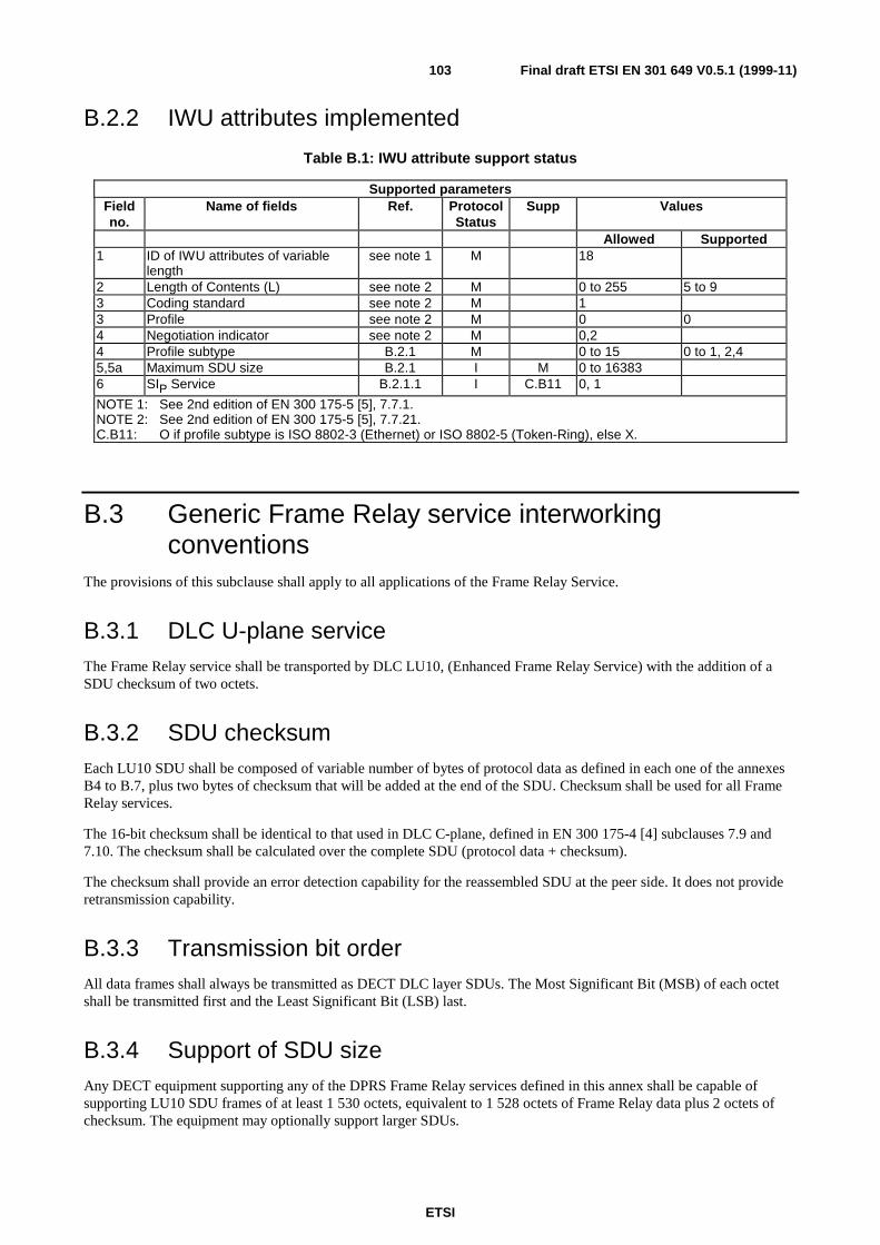
ETSI
Final draft ETSI EN 301 649 V0.5.1 (1999-11)103
B.2.2 IWU attributes implemented
Table B.1: IWU attribute support status
Supported parametersFieldno.
Name of fields Ref. ProtocolStatus
Supp Values
Allowed Supported1 ID of IWU attributes of variable
lengthsee note 1 M 18
2 Length of Contents (L) see note 2 M 0 to 255 5 to 93 Coding standard see note 2 M 13 Profile see note 2 M 0 04 Negotiation indicator see note 2 M 0,24 Profile subtype B.2.1 M 0 to 15 0 to 1, 2,45,5a Maximum SDU size B.2.1 I M 0 to 163836 SIP Service B.2.1.1 I C.B11 0, 1
NOTE 1: See 2nd edition of EN 300 175-5 [5], 7.7.1.NOTE 2: See 2nd edition of EN 300 175-5 [5], 7.7.21.C.B11: O if profile subtype is ISO 8802-3 (Ethernet) or ISO 8802-5 (Token-Ring), else X.
B.3 Generic Frame Relay service interworkingconventions
The provisions of this subclause shall apply to all applications of the Frame Relay Service.
B.3.1 DLC U-plane serviceThe Frame Relay service shall be transported by DLC LU10, (Enhanced Frame Relay Service) with the addition of aSDU checksum of two octets.
B.3.2 SDU checksumEach LU10 SDU shall be composed of variable number of bytes of protocol data as defined in each one of the annexesB4 to B.7, plus two bytes of checksum that will be added at the end of the SDU. Checksum shall be used for all FrameRelay services.
The 16-bit checksum shall be identical to that used in DLC C-plane, defined in EN 300 175-4 [4] subclauses 7.9 and7.10. The checksum shall be calculated over the complete SDU (protocol data + checksum).
The checksum shall provide an error detection capability for the reassembled SDU at the peer side. It does not provideretransmission capability.
B.3.3 Transmission bit orderAll data frames shall always be transmitted as DECT DLC layer SDUs. The Most Significant Bit (MSB) of each octetshall be transmitted first and the Least Significant Bit (LSB) last.
B.3.4 Support of SDU sizeAny DECT equipment supporting any of the DPRS Frame Relay services defined in this annex shall be capable ofsupporting LU10 SDU frames of at least 1 530 octets, equivalent to 1 528 octets of Frame Relay data plus 2 octets ofchecksum. The equipment may optionally support larger SDUs.
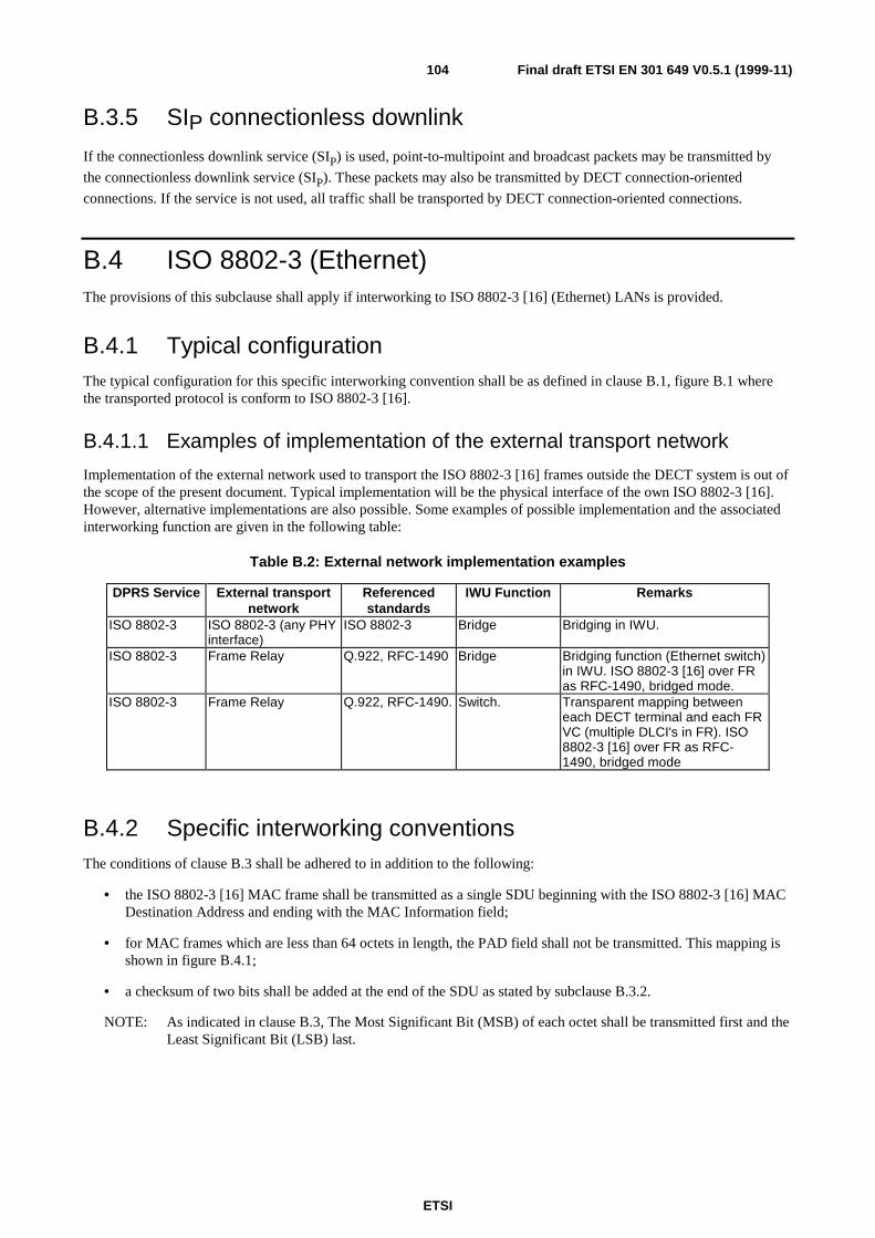
ETSI
Final draft ETSI EN 301 649 V0.5.1 (1999-11)104
B.3.5 SIP connectionless downlink
If the connectionless downlink service (SIP) is used, point-to-multipoint and broadcast packets may be transmitted by
the connectionless downlink service (SIP). These packets may also be transmitted by DECT connection-oriented
connections. If the service is not used, all traffic shall be transported by DECT connection-oriented connections.
B.4 ISO 8802-3 (Ethernet)The provisions of this subclause shall apply if interworking to ISO 8802-3 [16] (Ethernet) LANs is provided.
B.4.1 Typical configurationThe typical configuration for this specific interworking convention shall be as defined in clause B.1, figure B.1 wherethe transported protocol is conform to ISO 8802-3 [16].
B.4.1.1 Examples of implementation of the external transport network
Implementation of the external network used to transport the ISO 8802-3 [16] frames outside the DECT system is out ofthe scope of the present document. Typical implementation will be the physical interface of the own ISO 8802-3 [16].However, alternative implementations are also possible. Some examples of possible implementation and the associatedinterworking function are given in the following table:
Table B.2: External network implementation examples
DPRS Service External transportnetwork
Referencedstandards
IWU Function Remarks
ISO 8802-3 ISO 8802-3 (any PHYinterface)
ISO 8802-3 Bridge Bridging in IWU.
ISO 8802-3 Frame Relay Q.922, RFC-1490 Bridge Bridging function (Ethernet switch)in IWU. ISO 8802-3 [16] over FRas RFC-1490, bridged mode.
ISO 8802-3 Frame Relay Q.922, RFC-1490. Switch. Transparent mapping betweeneach DECT terminal and each FRVC (multiple DLCI's in FR). ISO8802-3 [16] over FR as RFC-1490, bridged mode
B.4.2 Specific interworking conventionsThe conditions of clause B.3 shall be adhered to in addition to the following:
• the ISO 8802-3 [16] MAC frame shall be transmitted as a single SDU beginning with the ISO 8802-3 [16] MACDestination Address and ending with the MAC Information field;
• for MAC frames which are less than 64 octets in length, the PAD field shall not be transmitted. This mapping isshown in figure B.4.1;
• a checksum of two bits shall be added at the end of the SDU as stated by subclause B.3.2.
NOTE: As indicated in clause B.3, The Most Significant Bit (MSB) of each octet shall be transmitted first and theLeast Significant Bit (LSB) last.
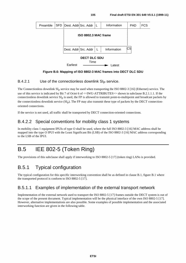
ETSI
Final draft ETSI EN 301 649 V0.5.1 (1999-11)105
TimeEarliest Latest
Preamble Dest. Addr L Information PAD FCSSFD Src. Addr
Dest. Addr L InformationSrc. Addr
ISO 8802.3 MAC frame
DECT DLC SDU
CS
Figure B.6: Mapping of ISO 8802-3 MAC frames into DECT DLC SDU
B.4.2.1 Use of the connectionless downlink SIP service.
The Connectionless downlink SIP service may be used when transporting the ISO 8802-3 [16] (Ethernet) service. The
use of this service is indicated by Bit 7 of Octet 6 of <<IWU-ATTRIBUTES>> shown in subclause B.2.1.1.1. If theconnectionless downlink service SIP is used, the FP is allowed to transmit point-to-multipoint and broadcast packets by
the connectionless downlink service (SIP). The FP may also transmit these type of packets by the DECT connection-
oriented connections.
If the service is not used, all traffic shall be transported by DECT connection-oriented connections.
B.4.2.2 Special conventions for mobility class 1 systems
In mobility class 1 equipment IPUIs of type O shall be used, where the full ISO 8802-3 [16] MAC address shall bemapped into the type O IPUI with the Least Significant Bit (LSB) of the ISO 8802-3 [16] MAC address correspondingto the LSB of the IPUI.
B.5 IEE 802-5 (Token Ring)The provisions of this subclause shall apply if interworking to ISO 8802-5 [17] (token ring) LANs is provided.
B.5.1 Typical configurationThe typical configuration for this specific interworking convention shall be as defined in clause B.1, figure B.1 wherethe transported protocol is conform to ISO 8802-5 [17].
B.5.1.1 Examples of implementation of the external transport network
Implementation of the external network used to transport the ISO 8802-5 [17] frames outside the DECT system is out ofthe scope of the present document. Typical implementation will be the physical interface of the own ISO 8802-5 [17].However, alternative implementations are also possible. Some examples of possible implementation and the associatedinterworking function are given in the following table.
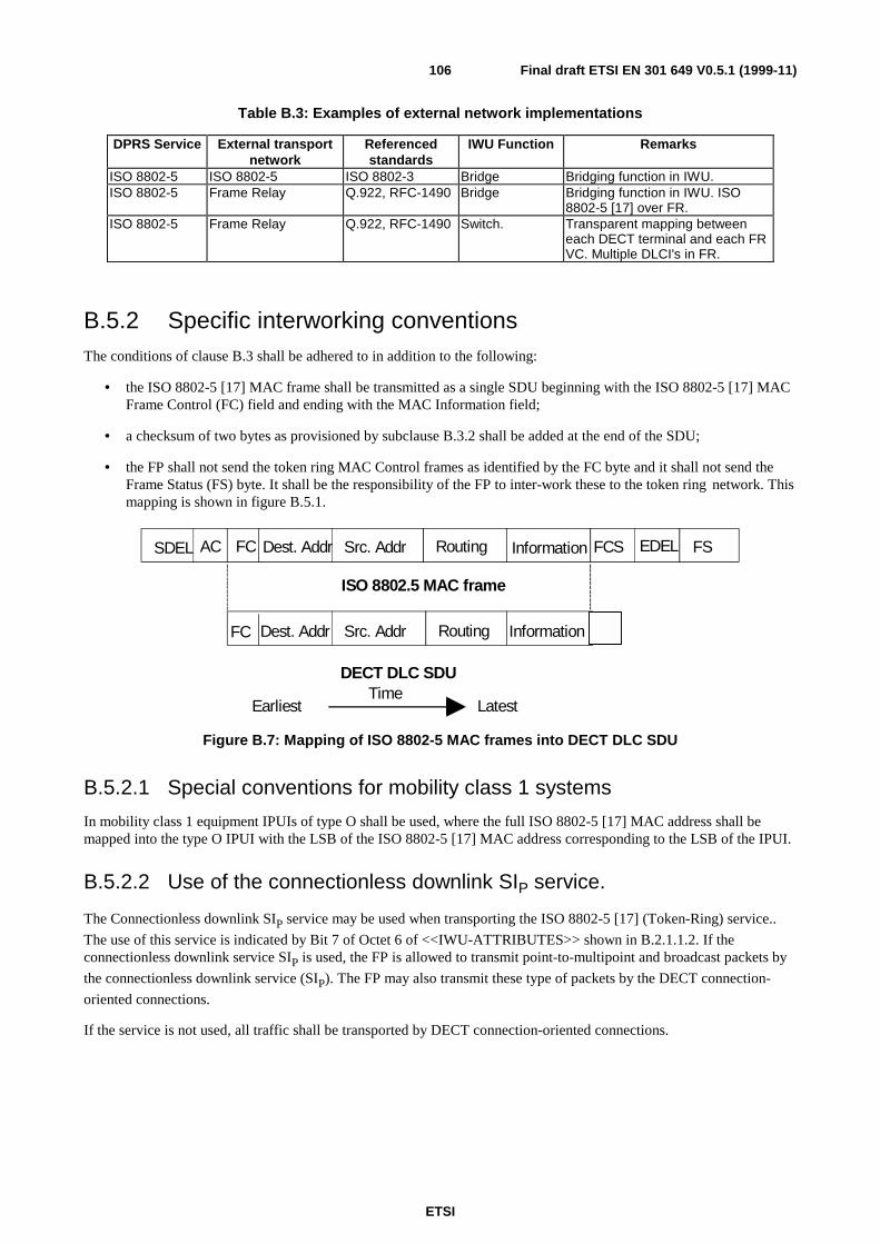
ETSI
Final draft ETSI EN 301 649 V0.5.1 (1999-11)106
Table B.3: Examples of external network implementations
DPRS Service External transportnetwork
Referencedstandards
IWU Function Remarks
ISO 8802-5 ISO 8802-5 ISO 8802-3 Bridge Bridging function in IWU.ISO 8802-5 Frame Relay Q.922, RFC-1490 Bridge Bridging function in IWU. ISO
8802-5 [17] over FR.ISO 8802-5 Frame Relay Q.922, RFC-1490 Switch. Transparent mapping between
each DECT terminal and each FRVC. Multiple DLCI's in FR.
B.5.2 Specific interworking conventionsThe conditions of clause B.3 shall be adhered to in addition to the following:
• the ISO 8802-5 [17] MAC frame shall be transmitted as a single SDU beginning with the ISO 8802-5 [17] MACFrame Control (FC) field and ending with the MAC Information field;
• a checksum of two bytes as provisioned by subclause B.3.2 shall be added at the end of the SDU;
• the FP shall not send the token ring MAC Control frames as identified by the FC byte and it shall not send theFrame Status (FS) byte. It shall be the responsibility of the FP to inter-work these to the token ring network. Thismapping is shown in figure B.5.1.
TimeEarliest Latest
Dest. Addr Information FCSSrc. Addr
ISO 8802.5 MAC frame
DECT DLC SDU
SDEL EDELRouting FSFCAC
Dest. Addr InformationSrc. Addr RoutingFC
Figure B.7: Mapping of ISO 8802-5 MAC frames into DECT DLC SDU
B.5.2.1 Special conventions for mobility class 1 systems
In mobility class 1 equipment IPUIs of type O shall be used, where the full ISO 8802-5 [17] MAC address shall bemapped into the type O IPUI with the LSB of the ISO 8802-5 [17] MAC address corresponding to the LSB of the IPUI.
B.5.2.2 Use of the connectionless downlink SIP service.
The Connectionless downlink SIP service may be used when transporting the ISO 8802-5 [17] (Token-Ring) service..
The use of this service is indicated by Bit 7 of Octet 6 of <<IWU-ATTRIBUTES>> shown in B.2.1.1.2. If theconnectionless downlink service SIP is used, the FP is allowed to transmit point-to-multipoint and broadcast packets by
the connectionless downlink service (SIP). The FP may also transmit these type of packets by the DECT connection-
oriented connections.
If the service is not used, all traffic shall be transported by DECT connection-oriented connections.
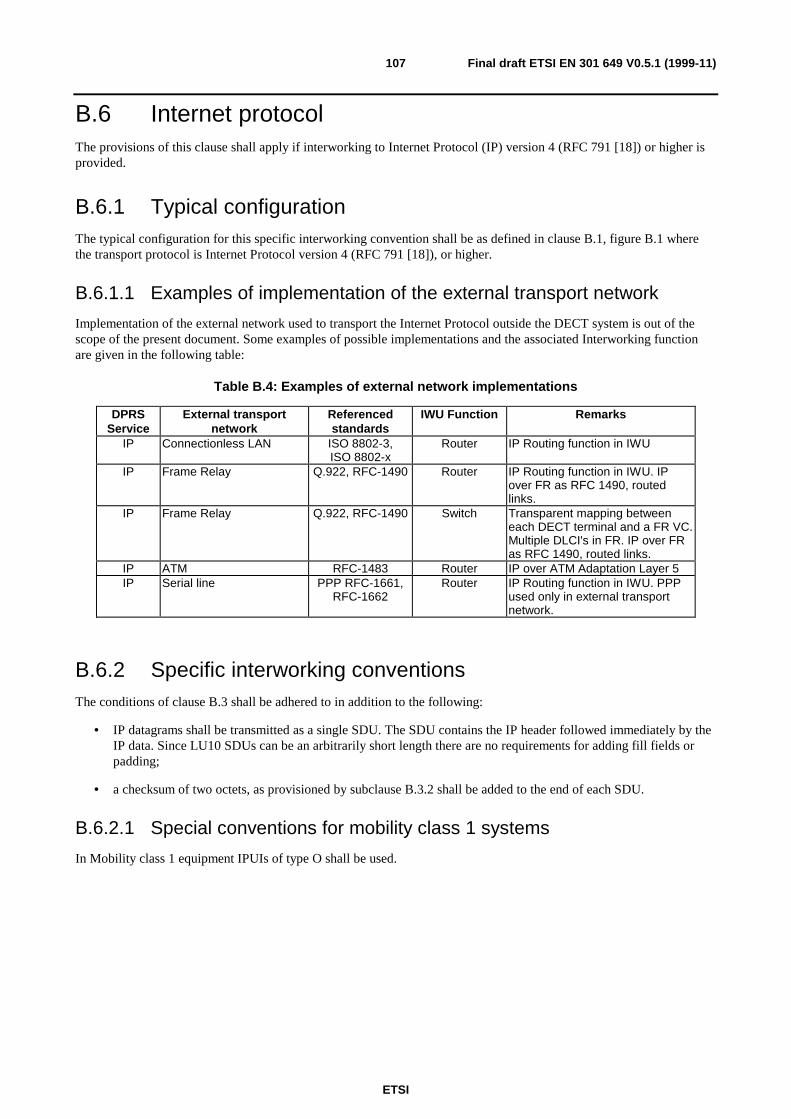
ETSI
Final draft ETSI EN 301 649 V0.5.1 (1999-11)107
B.6 Internet protocolThe provisions of this clause shall apply if interworking to Internet Protocol (IP) version 4 (RFC 791 [18]) or higher isprovided.
B.6.1 Typical configurationThe typical configuration for this specific interworking convention shall be as defined in clause B.1, figure B.1 wherethe transport protocol is Internet Protocol version 4 (RFC 791 [18]), or higher.
B.6.1.1 Examples of implementation of the external transport network
Implementation of the external network used to transport the Internet Protocol outside the DECT system is out of thescope of the present document. Some examples of possible implementations and the associated Interworking functionare given in the following table:
Table B.4: Examples of external network implementations
DPRSService
External transportnetwork
Referencedstandards
IWU Function Remarks
IP Connectionless LAN ISO 8802-3,ISO 8802-x
Router IP Routing function in IWU
IP Frame Relay Q.922, RFC-1490 Router IP Routing function in IWU. IPover FR as RFC 1490, routedlinks.
IP Frame Relay Q.922, RFC-1490 Switch Transparent mapping betweeneach DECT terminal and a FR VC.Multiple DLCI's in FR. IP over FRas RFC 1490, routed links.
IP ATM RFC-1483 Router IP over ATM Adaptation Layer 5IP Serial line PPP RFC-1661,
RFC-1662Router IP Routing function in IWU. PPP
used only in external transportnetwork.
B.6.2 Specific interworking conventionsThe conditions of clause B.3 shall be adhered to in addition to the following:
• IP datagrams shall be transmitted as a single SDU. The SDU contains the IP header followed immediately by theIP data. Since LU10 SDUs can be an arbitrarily short length there are no requirements for adding fill fields orpadding;
• a checksum of two octets, as provisioned by subclause B.3.2 shall be added to the end of each SDU.
B.6.2.1 Special conventions for mobility class 1 systems
In Mobility class 1 equipment IPUIs of type O shall be used.
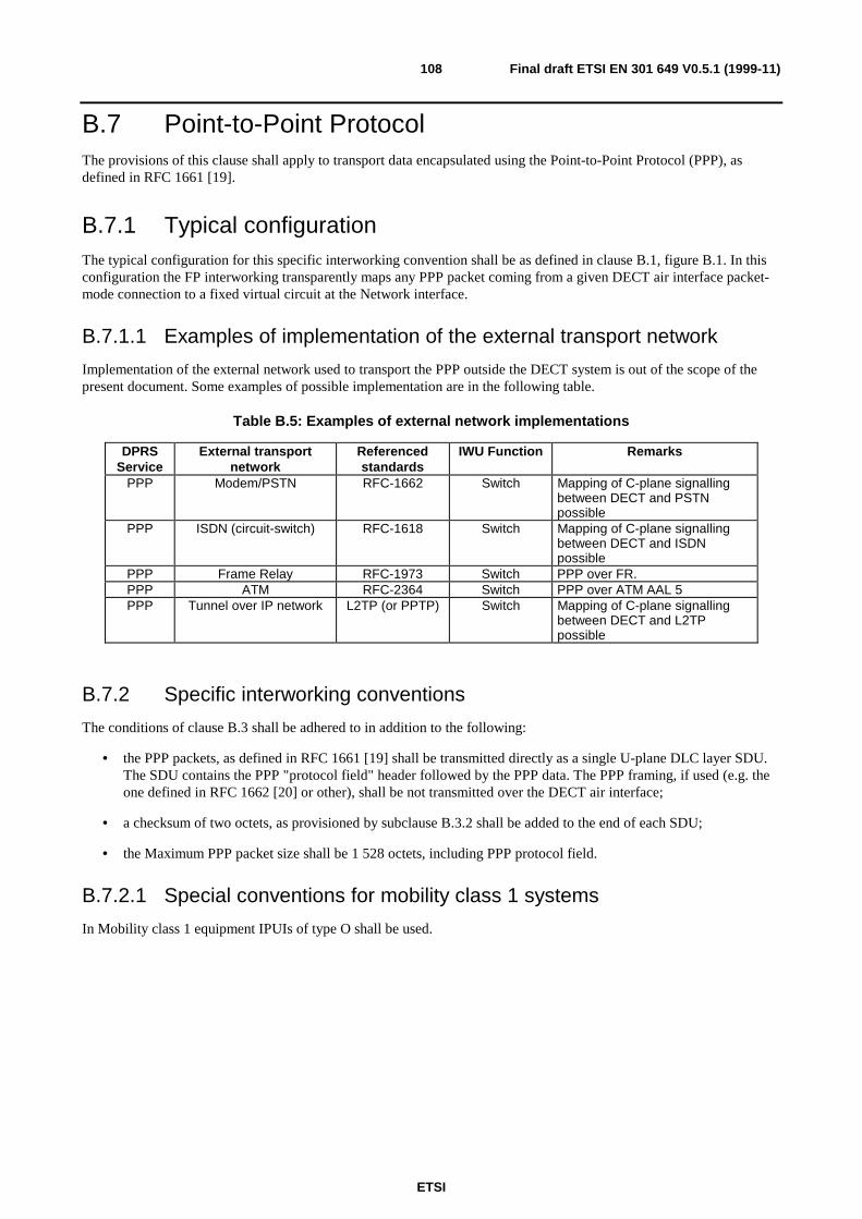
ETSI
Final draft ETSI EN 301 649 V0.5.1 (1999-11)108
B.7 Point-to-Point ProtocolThe provisions of this clause shall apply to transport data encapsulated using the Point-to-Point Protocol (PPP), asdefined in RFC 1661 [19].
B.7.1 Typical configurationThe typical configuration for this specific interworking convention shall be as defined in clause B.1, figure B.1. In thisconfiguration the FP interworking transparently maps any PPP packet coming from a given DECT air interface packet-mode connection to a fixed virtual circuit at the Network interface.
B.7.1.1 Examples of implementation of the external transport network
Implementation of the external network used to transport the PPP outside the DECT system is out of the scope of thepresent document. Some examples of possible implementation are in the following table.
Table B.5: Examples of external network implementations
DPRSService
External transportnetwork
Referencedstandards
IWU Function Remarks
PPP Modem/PSTN RFC-1662 Switch Mapping of C-plane signallingbetween DECT and PSTNpossible
PPP ISDN (circuit-switch) RFC-1618 Switch Mapping of C-plane signallingbetween DECT and ISDNpossible
PPP Frame Relay RFC-1973 Switch PPP over FR.PPP ATM RFC-2364 Switch PPP over ATM AAL 5PPP Tunnel over IP network L2TP (or PPTP) Switch Mapping of C-plane signalling
between DECT and L2TPpossible
B.7.2 Specific interworking conventions
The conditions of clause B.3 shall be adhered to in addition to the following:
• the PPP packets, as defined in RFC 1661 [19] shall be transmitted directly as a single U-plane DLC layer SDU.The SDU contains the PPP "protocol field" header followed by the PPP data. The PPP framing, if used (e.g. theone defined in RFC 1662 [20] or other), shall be not transmitted over the DECT air interface;
• a checksum of two octets, as provisioned by subclause B.3.2 shall be added to the end of each SDU;
• the Maximum PPP packet size shall be 1 528 octets, including PPP protocol field.
B.7.2.1 Special conventions for mobility class 1 systems
In Mobility class 1 equipment IPUIs of type O shall be used.
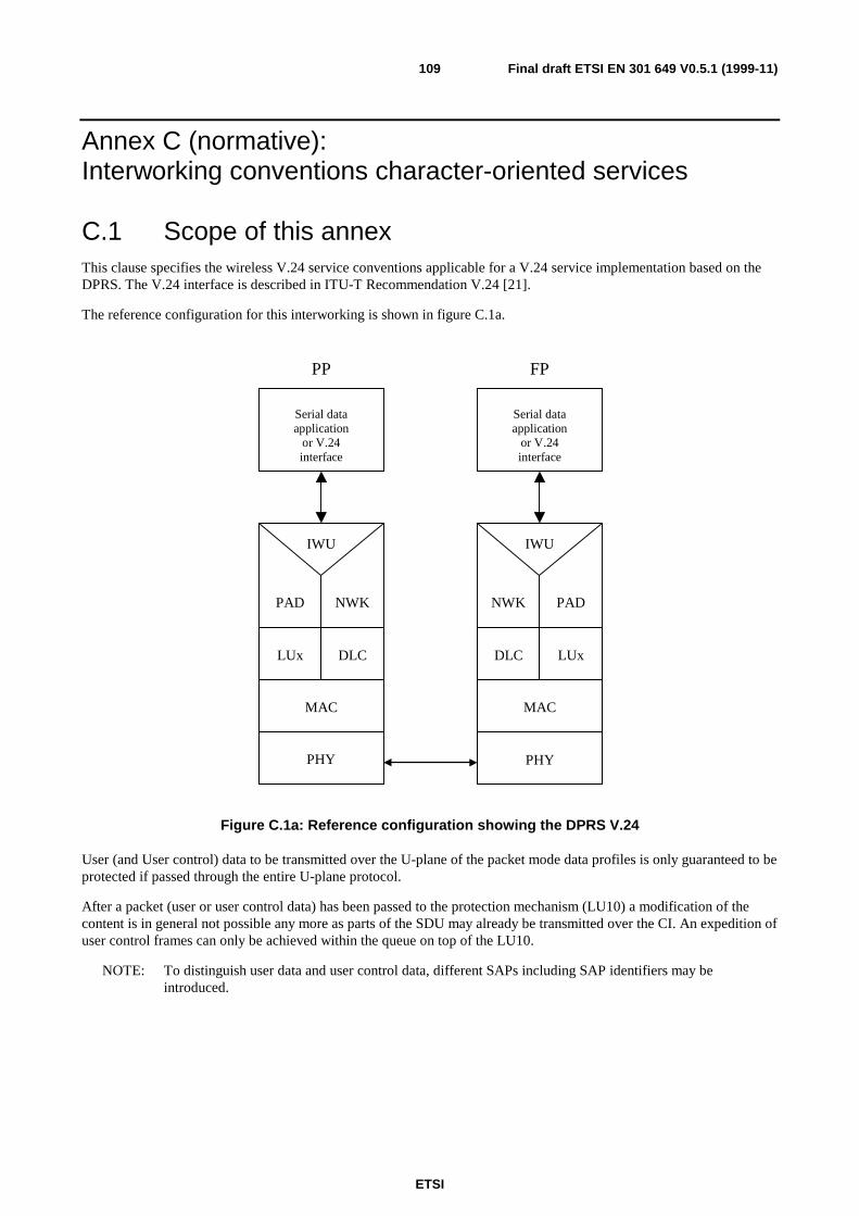
ETSI
Final draft ETSI EN 301 649 V0.5.1 (1999-11)109
Annex C (normative):Interworking conventions character-oriented services
C.1 Scope of this annexThis clause specifies the wireless V.24 service conventions applicable for a V.24 service implementation based on theDPRS. The V.24 interface is described in ITU-T Recommendation V.24 [21].
The reference configuration for this interworking is shown in figure C.1a.
NWK
DLC
MAC
IWU
PHY
NWK
DLC
IWU
PP FP
Serial dataapplication
or V.24interface
PAD
LUx
PAD
LUx
MAC
PHY
Serial dataapplication
or V.24interface
Figure C.1a: Reference configuration showing the DPRS V.24
User (and User control) data to be transmitted over the U-plane of the packet mode data profiles is only guaranteed to beprotected if passed through the entire U-plane protocol.
After a packet (user or user control data) has been passed to the protection mechanism (LU10) a modification of thecontent is in general not possible any more as parts of the SDU may already be transmitted over the CI. An expedition ofuser control frames can only be achieved within the queue on top of the LU10.
NOTE: To distinguish user data and user control data, different SAPs including SAP identifiers may beintroduced.

ETSI
Final draft ETSI EN 301 649 V0.5.1 (1999-11)110
IWF
LU10
PAD
SAP1 SAP2
Flow Ctrl
V24 -Application
SAP3
User data Flow Ctrl (locally, may be overlayed by E2Eand Path-By-Path)
SAP1: User Data SAPSAP2: User Control Data SAP (transfered with UIEs)SAP3: User Control Status Data SAP (transfered in each SDU-header)P2P-FL: Path-By-Path Flow Ctrl Interface
P2P-FL
Figure C.1b: SDU Data Flow
The following two scenarios describe different types of V.24-connections. Scenario A shows the normally configurationsuch as DTE <--> DCE (e.g. computer <--> modem). Scenario B shows a configuration such as DTE <--> DTE(e.g. computer <--> computer). Scenaria B is called nullmodem-connection.
DTE: data terminal equipment (e.g. computer).DCE: data circuit-terminating equipment (e.g. modem, ISDN-TA).
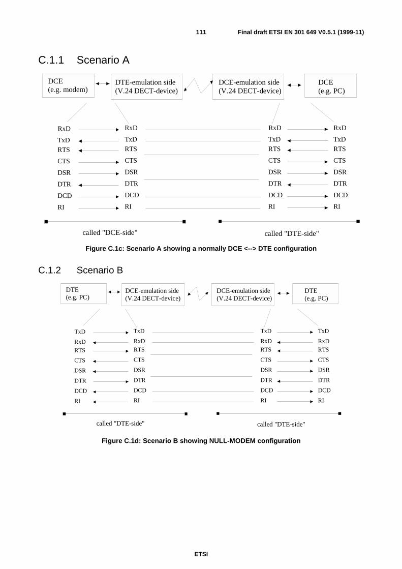
ETSI
Final draft ETSI EN 301 649 V0.5.1 (1999-11)111
C.1.1 Scenario A
RxD RxD RxD RxD
TxD TxD TxD TxD
RTS RTS RTS RTS
DCE(e.g. modem)
DCE(e.g. PC)
DTE-emulation side(V.24 DECT-device)
DCE-emulation side(V.24 DECT-device)
CTS CTS CTS CTS
DSR DSR DSR DSR
DCD DCD DCD DCD
DTR DTR DTR DTR
RI RI RI RI
called "DCE-side" called "DTE-side"
Figure C.1c: Scenario A showing a normally DCE <--> DTE configuration
C.1.2 Scenario B
TxD TxD TxD TxD
RxD RxD RxD RxD
RTS RTS RTS RTS
DTE(e.g. PC)
DTE(e.g. PC)
DCE-emulation side(V.24 DECT-device)
DCE-emulation side(V.24 DECT-device)
CTS CTS CTS CTS
DSR DSR DSR DSR
DCD DCD DCD DCD
DTR DTR DTR DTR
RI RI RI RI
called "DTE-side" called "DTE-side"
Figure C.1d: Scenario B showing NULL-MODEM configuration
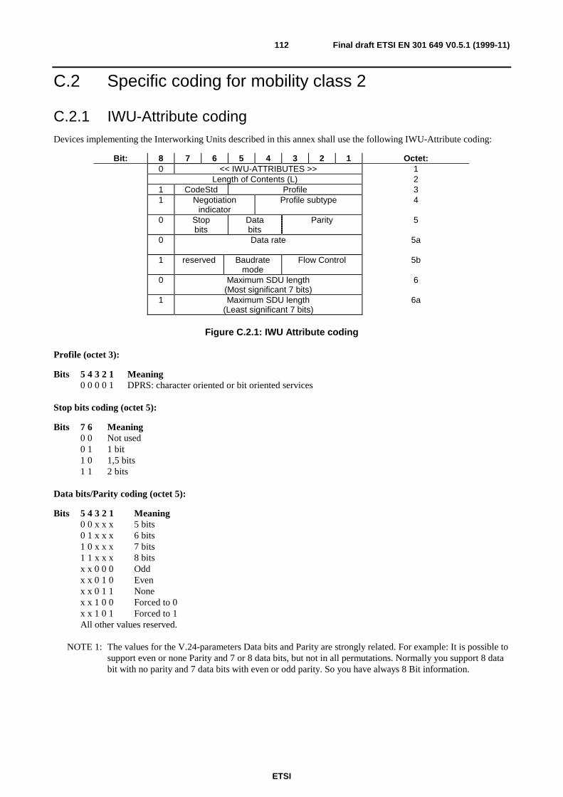
ETSI
Final draft ETSI EN 301 649 V0.5.1 (1999-11)112
C.2 Specific coding for mobility class 2
C.2.1 IWU-Attribute codingDevices implementing the Interworking Units described in this annex shall use the following IWU-Attribute coding:
Bit: 8 7 6 5 4 3 2 1 Octet:0 << IWU-ATTRIBUTES >> 1
Length of Contents (L) 21 CodeStd Profile 31 Negotiation
indicatorProfile subtype 4
0 Stopbits
Databits
Parity 5
0 Data rate 5a
1 reserved Baudratemode
Flow Control 5b
0 Maximum SDU length(Most significant 7 bits)
6
1 Maximum SDU length(Least significant 7 bits)
6a
Figure C.2.1: IWU Attribute coding
Profile (octet 3):
Bits 5 4 3 2 1 Meaning0 0 0 0 1 DPRS: character oriented or bit oriented services
Stop bits coding (octet 5):
Bits 7 6 Meaning0 0 Not used0 1 1 bit1 0 1,5 bits1 1 2 bits
Data bits/Parity coding (octet 5):
Bits 5 4 3 2 1 Meaning0 0 x x x 5 bits0 1 x x x 6 bits1 0 x x x 7 bits1 1 x x x 8 bitsx x 0 0 0 Oddx x 0 1 0 Evenx x 0 1 1 Nonex x 1 0 0 Forced to 0x x 1 0 1 Forced to 1All other values reserved.
NOTE 1: The values for the V.24-parameters Data bits and Parity are strongly related. For example: It is possible tosupport even or none Parity and 7 or 8 data bits, but not in all permutations. Normally you support 8 databit with no parity and 7 data bits with even or odd parity. So you have always 8 Bit information.
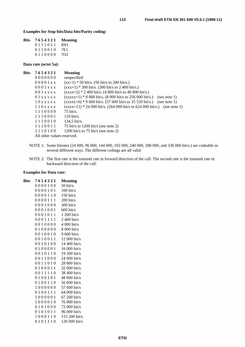
ETSI
Final draft ETSI EN 301 649 V0.5.1 (1999-11)113
Examples for Stop bits/Data bits/Parity coding:
Bits 7 6 5 4 3 2 1 Meaning0 1 1 1 0 1 1 8N10 1 1 0 0 1 0 7E10 1 1 0 0 0 0 7O1
Data rate (octet 5a):
Bits 7 6 5 4 3 2 1 Meaning0 0 0 0 0 0 0 unspecified0 0 0 0 1 x x (xx+1) * 50 bit/s. (50 bit/s to 200 bit/s.)0 0 0 1 x x x (xxx+1) * 300 bit/s. (300 bit/s to 2 400 bit/s.)0 0 1 x x x x (xxxx+2) * 2 400 bit/s. (4 800 bit/s to 40 800 bit/s.)0 1 x x x x x (xxxxx+1) * 8 000 bit/s. (8 000 bit/s to 256 000 bit/s.) (see note 1)1 0 x x x x x (xxxxx+6) * 9 600 bit/s. (57 600 bit/s to 35 520 bit/s.) (see note 1)1 1 0 x x x x (xxxx+11) * 24 000 bit/s. (264 000 bit/s to 624 000 bit/s.) (see note 1)1 1 1 0 0 0 0 75 bit/s.1 1 1 0 0 0 1 110 bit/s.1 1 1 0 0 1 0 134,5 bit/s.1 1 1 0 0 1 1 75 bit/s to 1200 bit/s (see note 2)1 1 1 0 1 0 0 1200 bit/s to 75 bit/s (see note 2)All other values reserved.
NOTE 1: Some bitrates (24 000, 96 000, 144 000, 192 000, 240 000, 288 000, and 336 000 bit/s.) are codeable inseveral different ways. The different codings are all valid.
NOTE 2: The first rate is the transmit rate in forward direction of the call. The second rate is the transmit rate inbackward direction of the call.
Examples for Data rate:
Bits 7 6 5 4 3 2 1 Meaning0 0 0 0 1 0 0 50 bit/s0 0 0 0 1 0 1 100 bit/s0 0 0 0 1 1 0 150 bit/s0 0 0 0 1 1 1 200 bit/s0 0 0 1 0 0 0 300 bit/s0 0 0 1 0 0 1 600 bit/s0 0 0 1 0 1 1 1 200 bit/s0 0 0 1 1 1 1 2 400 bit/s0 0 1 0 0 0 0 4 800 bit/s0 1 0 0 0 0 0 8 000 bit/s0 0 1 0 0 1 0 9 600 bit/s0 0 1 0 0 1 1 12 000 bit/s0 0 1 0 1 0 0 14 400 bit/s0 1 0 0 0 0 1 16 000 bit/s0 0 1 0 1 1 0 19 200 bit/s0 0 1 1 0 0 0 24 000 bit/s0 0 1 1 0 1 0 28 800 bit/s0 1 0 0 0 1 1 32 000 bit/s0 0 1 1 1 1 0 38 400 bit/s0 1 0 0 1 0 1 48 000 bit/s0 1 0 0 1 1 0 56 000 bit/s1 0 0 0 0 0 0 57 600 bit/s0 1 0 0 1 1 1 64 000 bit/s1 0 0 0 0 0 1 67 200 bit/s1 0 0 0 0 1 0 76 800 bit/s0 1 0 1 0 0 0 72 000 bit/s0 1 0 1 0 1 1 96 000 bit/s1 0 0 0 1 1 0 115 200 bit/s0 1 0 1 1 1 0 120 000 bit/s
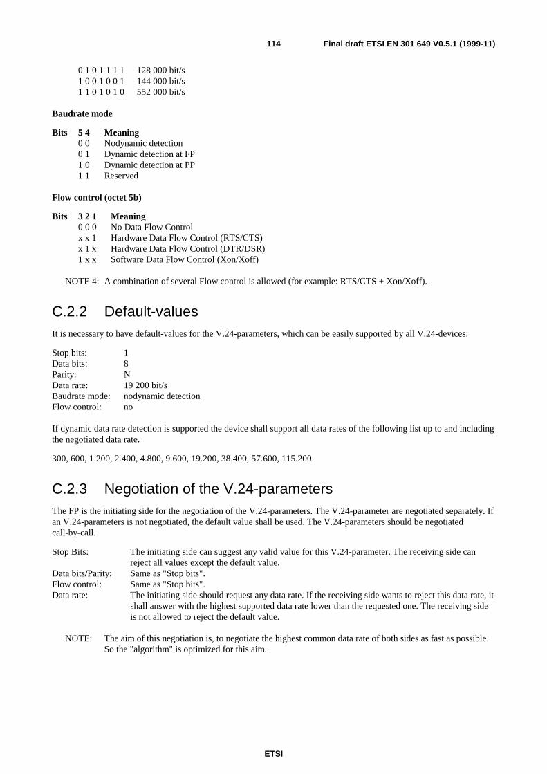
ETSI
Final draft ETSI EN 301 649 V0.5.1 (1999-11)114
0 1 0 1 1 1 1 128 000 bit/s1 0 0 1 0 0 1 144 000 bit/s1 1 0 1 0 1 0 552 000 bit/s
Baudrate mode
Bits 5 4 Meaning0 0 Nodynamic detection0 1 Dynamic detection at FP1 0 Dynamic detection at PP1 1 Reserved
Flow control (octet 5b)
Bits 3 2 1 Meaning0 0 0 No Data Flow Controlx x 1 Hardware Data Flow Control (RTS/CTS)x 1 x Hardware Data Flow Control (DTR/DSR)1 x x Software Data Flow Control (Xon/Xoff)
NOTE 4: A combination of several Flow control is allowed (for example: RTS/CTS + Xon/Xoff).
C.2.2 Default-valuesIt is necessary to have default-values for the V.24-parameters, which can be easily supported by all V.24-devices:
Stop bits: 1Data bits: 8Parity: NData rate: 19 200 bit/sBaudrate mode: nodynamic detectionFlow control: no
If dynamic data rate detection is supported the device shall support all data rates of the following list up to and includingthe negotiated data rate.
300, 600, 1.200, 2.400, 4.800, 9.600, 19.200, 38.400, 57.600, 115.200.
C.2.3 Negotiation of the V.24-parametersThe FP is the initiating side for the negotiation of the V.24-parameters. The V.24-parameter are negotiated separately. Ifan V.24-parameters is not negotiated, the default value shall be used. The V.24-parameters should be negotiatedcall-by-call.
Stop Bits: The initiating side can suggest any valid value for this V.24-parameter. The receiving side canreject all values except the default value.
Data bits/Parity: Same as "Stop bits".Flow control: Same as "Stop bits".Data rate: The initiating side should request any data rate. If the receiving side wants to reject this data rate, it
shall answer with the highest supported data rate lower than the requested one. The receiving sideis not allowed to reject the default value.
NOTE: The aim of this negotiation is, to negotiate the highest common data rate of both sides as fast as possible.So the "algorithm" is optimized for this aim.
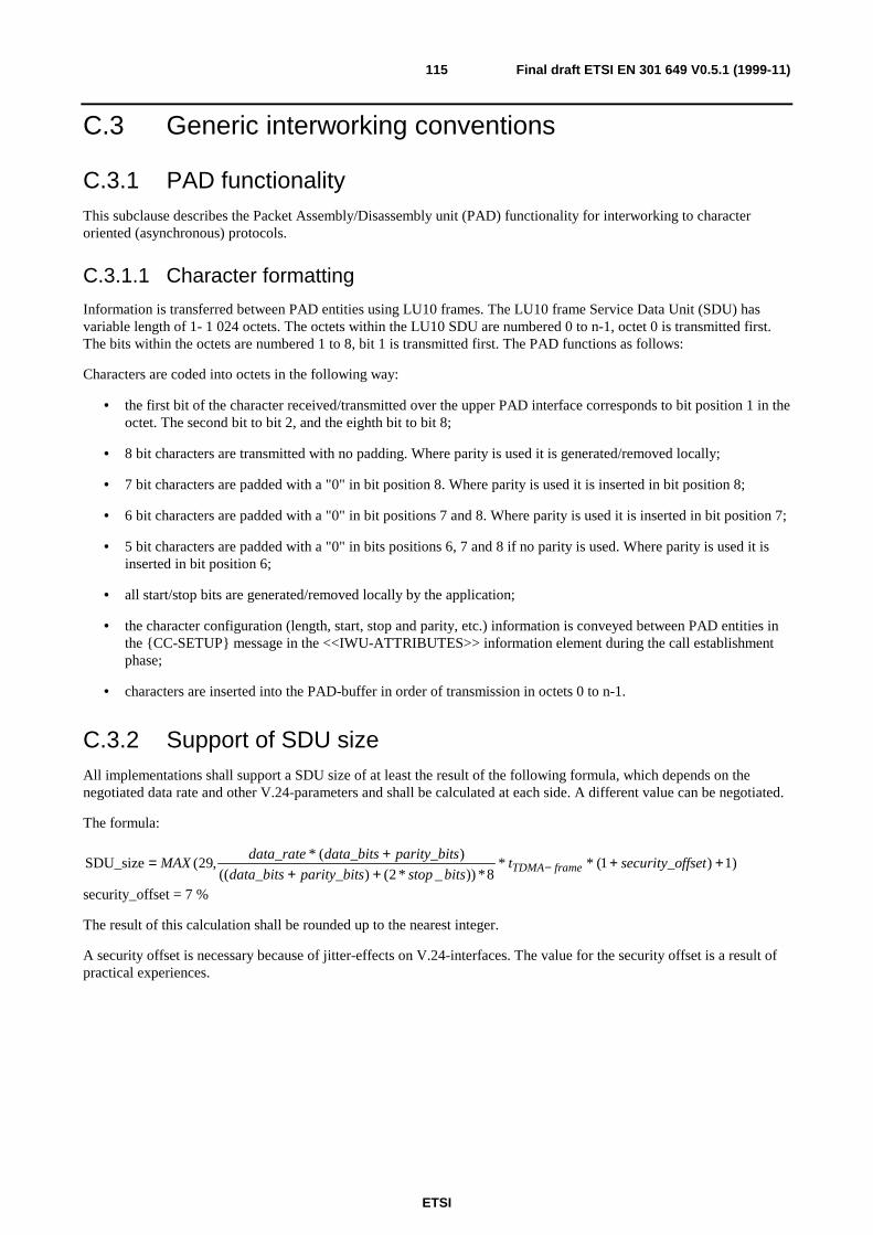
ETSI
Final draft ETSI EN 301 649 V0.5.1 (1999-11)115
C.3 Generic interworking conventions
C.3.1 PAD functionalityThis subclause describes the Packet Assembly/Disassembly unit (PAD) functionality for interworking to characteroriented (asynchronous) protocols.
C.3.1.1 Character formatting
Information is transferred between PAD entities using LU10 frames. The LU10 frame Service Data Unit (SDU) hasvariable length of 1- 1 024 octets. The octets within the LU10 SDU are numbered 0 to n-1, octet 0 is transmitted first.The bits within the octets are numbered 1 to 8, bit 1 is transmitted first. The PAD functions as follows:
Characters are coded into octets in the following way:
• the first bit of the character received/transmitted over the upper PAD interface corresponds to bit position 1 in theoctet. The second bit to bit 2, and the eighth bit to bit 8;
• 8 bit characters are transmitted with no padding. Where parity is used it is generated/removed locally;
• 7 bit characters are padded with a "0" in bit position 8. Where parity is used it is inserted in bit position 8;
• 6 bit characters are padded with a "0" in bit positions 7 and 8. Where parity is used it is inserted in bit position 7;
• 5 bit characters are padded with a "0" in bits positions 6, 7 and 8 if no parity is used. Where parity is used it isinserted in bit position 6;
• all start/stop bits are generated/removed locally by the application;
• the character configuration (length, start, stop and parity, etc.) information is conveyed between PAD entities inthe {CC-SETUP} message in the <<IWU-ATTRIBUTES>> information element during the call establishmentphase;
• characters are inserted into the PAD-buffer in order of transmission in octets 0 to n-1.
C.3.2 Support of SDU sizeAll implementations shall support a SDU size of at least the result of the following formula, which depends on thenegotiated data rate and other V.24-parameters and shall be calculated at each side. A different value can be negotiated.
The formula:
1))1(**8*))_*2()((
)(*,29(SDU_size ++
+++= − ffsetsecurity_ot
bitsstopsparity_bitdata_bits
sparity_bitdata_bitsdata_rateMAX frameTDMA
security_offset = 7 %
The result of this calculation shall be rounded up to the nearest integer.
A security offset is necessary because of jitter-effects on V.24-interfaces. The value for the security offset is a result ofpractical experiences.

ETSI
Final draft ETSI EN 301 649 V0.5.1 (1999-11)116
Table C.3.2.a: values for common data rates and V.24-parameters
Data rate Data bits/Parity/Stopbits
Max. supported SDU size
1.200 8N1, 7E1, 7O1 292.400 8N1, 7E1, 7O1 294.800 8N1, 7E1, 7O1 299.600 8N1, 7E1, 7O1 29
19.200 8N1, 7E1, 7O1 2938.400 8N1, 7E1, 7O1 4357.600 8N1, 7E1, 7O1 63
115.200 8N1, 7E1, 7O1 125
C.4 V.24 circuits
C.4.1 GeneralThe IWU of V.24 DPRS shall support the functionality of CCITT Recommendation V.24 [21] for the following lines:
Table C.1: IWU V.24 support
Circuit Meaning Direction103 Transmit Data (TxD) To DCE104 Receive Data (RxD) From DCE105 Request to Send (RTS) To DCE106 Clear to Send (CTS) From DCE107 Data Set Ready (DSR) From DCE108 Data Terminal Ready (DTR) To DCE109 Data Carrier Detect (DCD) From DCE125 Ring Indicator (RI) From DCE
Additional functionality are:
• Xon, Xoff;
• Break and Pause.
NOTE: Indication of break and pause conditions are not foreseen as they are not required for proper operation innearly all cases.
If supported, the break and pause conditions shall be optional and therefore be transmitted within an optional usercontrol information element as described above.
The V.24 connection establishment shall not influence DECT call control. The call control is only necessary to establishthe connection and configure the serial port such as data coding, data rate, etc.
All information (signalling- and user data) of the V.24 connection is transferred via an encapsulation protocol.
C.4.2 Encapsulation
C.4.2.1 Description
For transmission an one byte header is inserted to multiplex signal-, control- or userdata on the same DECT-data link.
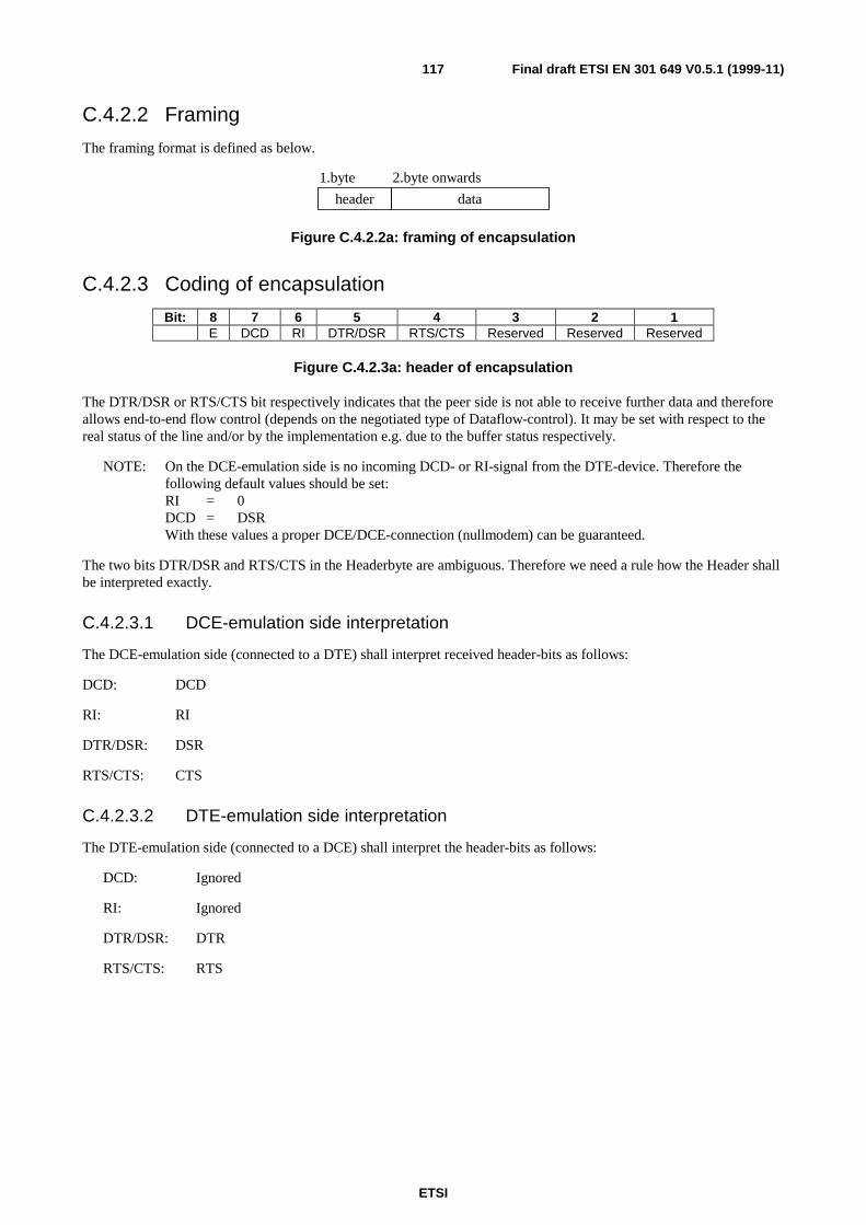
ETSI
Final draft ETSI EN 301 649 V0.5.1 (1999-11)117
C.4.2.2 Framing
The framing format is defined as below.
header data
1.byte 2.byte onwards
Figure C.4.2.2a: framing of encapsulation
C.4.2.3 Coding of encapsulation
Bit: 8 7 6 5 4 3 2 1E DCD RI DTR/DSR RTS/CTS Reserved Reserved Reserved
Figure C.4.2.3a: header of encapsulation
The DTR/DSR or RTS/CTS bit respectively indicates that the peer side is not able to receive further data and thereforeallows end-to-end flow control (depends on the negotiated type of Dataflow-control). It may be set with respect to thereal status of the line and/or by the implementation e.g. due to the buffer status respectively.
NOTE: On the DCE-emulation side is no incoming DCD- or RI-signal from the DTE-device. Therefore thefollowing default values should be set:RI = 0DCD = DSRWith these values a proper DCE/DCE-connection (nullmodem) can be guaranteed.
The two bits DTR/DSR and RTS/CTS in the Headerbyte are ambiguous. Therefore we need a rule how the Header shallbe interpreted exactly.
C.4.2.3.1 DCE-emulation side interpretation
The DCE-emulation side (connected to a DTE) shall interpret received header-bits as follows:
DCD: DCD
RI: RI
DTR/DSR: DSR
RTS/CTS: CTS
C.4.2.3.2 DTE-emulation side interpretation
The DTE-emulation side (connected to a DCE) shall interpret the header-bits as follows:
DCD: Ignored
RI: Ignored
DTR/DSR: DTR
RTS/CTS: RTS
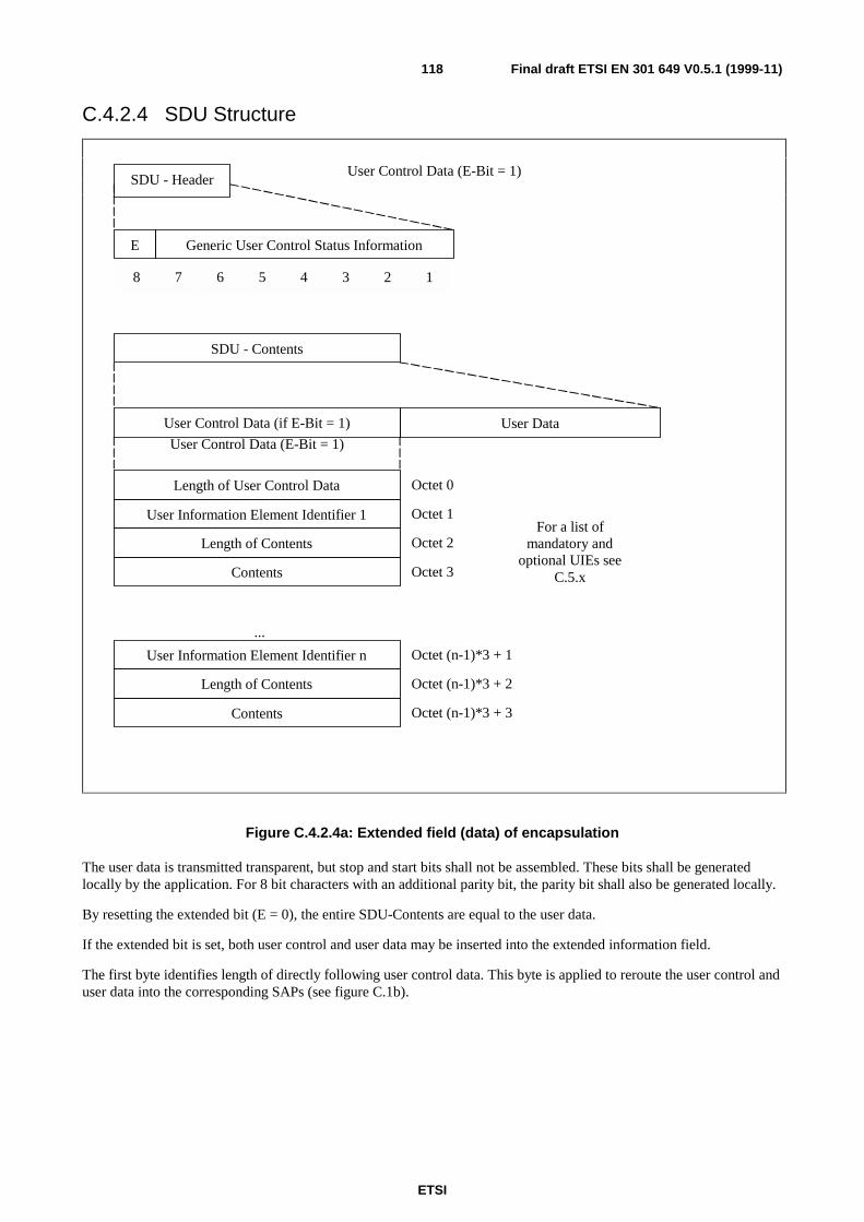
ETSI
Final draft ETSI EN 301 649 V0.5.1 (1999-11)118
C.4.2.4 SDU Structure
User Control Data (E-Bit = 1)SDU - Header
E Generic User Control Status Information
SDU - Contents
User Control Data (if E-Bit = 1)
User Control Data (E-Bit = 1)
User Data
User Information Element Identifier 1 Octet 1
Length of Contents Octet 2
...
For a list ofmandatory and
optional UIEs seeC.5.x
8 7 6 5 4 3 2 1
Contents
User Information Element Identifier n
Length of Contents
Contents
Octet 3
Length of User Control Data Octet 0
Octet (n-1)*3 + 1
Octet (n-1)*3 + 2
Octet (n-1)*3 + 3
Figure C.4.2.4a: Extended field (data) of encapsulation
The user data is transmitted transparent, but stop and start bits shall not be assembled. These bits shall be generatedlocally by the application. For 8 bit characters with an additional parity bit, the parity bit shall also be generated locally.
By resetting the extended bit (E = 0), the entire SDU-Contents are equal to the user data.
If the extended bit is set, both user control and user data may be inserted into the extended information field.
The first byte identifies length of directly following user control data. This byte is applied to reroute the user control anduser data into the corresponding SAPs (see figure C.1b).

ETSI
Final draft ETSI EN 301 649 V0.5.1 (1999-11)119
C.4.3 Interworking procedures and conventions
C.4.3.1 General
C.4.3.1.1 Data forwarding conditions
Userdata and signalling data shall be assembled until one or more of the following conditions is met:
• a timer expires at any time;
• the SDU is forwarded to U-plane service entity.
C.4.3.1.2 Dataflow Control
The dataflow shall take action local but shall be overlayed by Path-By Path or End-2-End Flow Control. Exception: It isnot allowed to overlay an active local flow control with an inactive Path-By-Path or End-2-End flow control. Thecontrol information shall be generated by U-plane service or set over V.24 interface.
C.4.3.1.2.1 Software dataflow control
If the IWU notifies that the U-plane service is not ready to transfer data, it shall generate an Xoff. If the U-plane serviceindicates the data should be transmitted once again the IWU shall generate an Xon.
If the IWU notifies that an Xoff is received by V.24 interface, the IWU shall stop to transmit data over V.24 interface. Ifthe Xon identify is received at V.24 interface the IWU start to transmit once again.
C.4.3.1.2.2 Hardware dataflow control
The flow control condition indication shall be performed using circuits RTS/CTS or circuits DTR/DSR, in these cases:
At DCE-emulation side IWU interface (connected to a DTE):
• a DCE-emulation side IWU not-ready condition, initiated U-plane service, shall be indicated by turning circuit106 (CTS) or 107 (DSR) OFF and cleared by turning circuit 106(CTS) or 107(DSR) ON;
• a DTE not ready condition shall be recognized by an ON-OFF transition and cleared by an OFF-ON transition ofcircuit 105 (RTS) or 108 (DTR).
At DTE-emulation side IWU interface (connected to a DCE):
• a DTE-emulation side IWU not-ready condition, initiated U-plane service, shall be indicated by turning circuit105 (RTS) or 108 (DTR) OFF and cleared by turning circuit 105 (RTS) or 108 (DTR) ON;
• a DCE not ready condition shall be recognized by an ON-OFF transition and cleared by an OFF-ON transition ofcircuit 106(CTS) or 107(DSR).
NOTE: on running system, either DTR/DSR or RTS/CTS mode is available. This is set in the IWU-Attribute
C.4.3.1.3 Transmission of U-plane data procedure
If the SDU is forwarded to U-plane service entity, the actual line states of V.24 are inserted into the header (done by theapplication).
C.4.3.1.4 Receive of U-plane data procedure
The header is to compare if line states of V.24 connection have been changed.
ETSI
Final draft ETSI EN 301 649 V0.5.1 (1999-11)120
C.4.3.1.5 V.24 signalling
The circuits 106 (CTS) /105 (RTS) or 107 (DSR)/108 (DTR) shall be generated locally and maybe overlayed by Path-By-Path or End-2-End flow control.
C.4.3.1.6 Configuration a V.24 interface during a Connection
The initiating side:
The IWU shall stop the user data transmission by using the dataflow control, it sends also the remaining data intotransmit buffers and shall issue MMCC_MODIFY.req, specifying the configuration of serial interface and link, and shallawait a MMCC_MODIFY.cfm primitive. If this primitive notifies failure, it shall enter the release-procedure, otherwisethe dataflow control enable the data flow.
The destination side:
If the IWU receives a MMCC_MODIFY.ind, it shall stop the data transmission by using the dataflow control,afterwards the buffer shall be cleared, the serial port shall be configure and shall await incoming data of the initiatingside.
NOTE: It is not necessary in all MNCC_MODIFY-events to stop the data transmission etc. (for example:bandwidth-modification).
C.4.3.2 Fall back procedure
If the DECT-Link breaks off, the DCE-emulation side IWU shall clear the buffer and turn circuit 107 (DSR)/106 (CTS),circuit 125 (RI) and circuit 109 (DCD) off, the DTE-emulation side IWU shall clear the buffer and turn circuit108 (DTR) and circuit 105 (RTS) off.
C.4.3.3 Procedure at the DCE-emulation side IWU
The IWU shall emulate a DCE. Received Data (from the air-interface) shall be forwarded via the circuit RxD to theDTE and V.24-data shall be received via the circuit TxD from the DTE. (see figure C.1c for details).
NOTE: The dataflow control is not special notified. It is defined in C.4.3.1.2.
C.4.3.3.1 DTE- initiated VC establishment
If no V.24 call is established, then the IWU shall monitor the value of all state-lines. If DTR line goes ON, the IWUshall monitor the activity of the circuit TxD. The circuit TxD shall also be monitored, if no dataflow mode is negotiated.If data is detected on the circuit TxD line or a state on the state-lines is changed, then the IWU shall issue anMNCC_SETUP.req primitive and change the state to "V.24 call Requested".
In the "V.24 call Requested" state, if the IWU receives a MNCC_REJECT.ind primitive, it shall clear the buffer and setDSR-, CTS-, RI- and DCD-line OFF and shall return to the "No V.24 call" state. Its subsequent action shall be locallydetermined on the basis of the release reason contained in the primitive.
In the "V.24 call Requested" state, if the IWU receives an MNCC_CONNECT.ind primitive it shall enter a "V.24 callActive" state. Other primitives might be received before MNCC_CONNECT.
C.4.3.3.2 DCE-initiated VC establishment
Upon the receipt of a MNCC_SETUP.ind primitive, the IWU shall determine that the service requested may be offered,and if so it will issue a MNCC_CONNECT.ind primitive and enter the "V.24 call Active" state. . Other primitives mightbe sent before MNCC_CONNECT.
If the service cannot be supported, it will issue a MNCC_REJECT.req, indicating a release reason, and will return to the"No V.24 call" state.
ETSI
Final draft ETSI EN 301 649 V0.5.1 (1999-11)121
C.4.3.3.3 V.24 call release
The application shall decide in which cases the V.24 call should be released. The V.24 call release shall be done usingthe NWK Call release procedure (see GAP).
C.4.3.4 Procedure at the DTE-emulation side IWU
The IWU shall emulate a DTE. Received data (from the air-interface) shall be forwarded via the circuit TxD to the DCEand V.24-data shall be received via the circuit RxD from the DCE (see figure C.1c for details).
C.4.3.4.1 DCE-initiated VC establishment
If no V.24 call is established, then the IWU shall monitor the value of all state-lines. If the DSR line goes ON, then theIWU shall monitor the activity of the circuit RxD. The circuit RxD shall also be monitored, if no dataflow mode isnegotiated. If data is then detected on the circuit RxD line, or any state line is changed, then the IWU shall issue anMNCC_SETUP.req primitive and shall enter the "V.24 Call Requested" state.
In this state, if the IWU receives a MNCC_REJECT.ind primitive, it shall clear the buffer and shall return to the "NoV.24 Call" state. Its subsequent action shall be locally determined on the basis of the release reason contained in theprimitive.
In the "V.24 Call Requested" state, if the IWU receives an MNCC_CONNECT.ind primitive it shall enter a "V.24 CallActive" state. Other primitives might be received before MNCC_CONNECT.
C.4.3.4.2 DTE-initiated VC establishment
Upon the receipt of a MNCC_SETUP.ind primitive, the IWU shall determine that the service requested may be offered,and if so it will issue a MNCC_CONNECT.ind primitive and enter the "V.24 Call Active" state. . Other primitives mightbe sent before MNCC_CONNECT.
Once in this state, it shall set the value of the DTR line to the value communicated to it by U-plane service. If the servicecannot be supported, it will issue a MNCC_REJECT.req, indicating a release reason, and will return to the "No V.24Call" state.
C.4.3.4.3 V.24 call release
The application shall decide in which cases the V.24 call should be released. The V.24 call release shall be done usingthe NWK Call release procedure (see [8]).
C.5 Definition of User Control Information ElementsUIEs can be send within each SDU. It is allowed to send user data and UIEs in one SDU (see subclause C.4.2.4).
C.5.1 Mandatory UIEsNo mandatory UIEs at this time.
C.5.2 Optional UIEsA device can send the UIE <release_reason> at any time. If a device receives this UIE it can decide how to react.
ETSI
Final draft ETSI EN 301 649 V0.5.1 (1999-11)122
UIE_RELEASE_REASON:
Field Code CommentTag UIE_RELEASE_REASON Release ReasonLength 1 1 byte followingValue Bits 8 7 6 5 4 3 2 1
0 x x x x x x x1 0 0 0 0 0 0 0
All other values reserved.
Proprietary reasonsReason not known
Some operating systems (e.g. Unix) sometimes use a special behaviour of the start- and stop-bit. To support thisbehaviour, the following two UIEs are necessary.
BREAK_CONDITION:
Field Code CommentTag UIE_BREAK_CONDITION Break ConditionLength 1 1 byte followingValue 0 to 255 Unit: 10 milliseconds
PAUSE_CONDITION:
Field Code CommentTag UIE_PAUSE_CONDITION Pause ConditionLength 1 1 byte followingValue 0 to 255 Unit: 10 milliseconds
C.5.3 Information Element Identifier
Information Element Identifier (Tag):
Bits 8 7 6 5 4 3 2 1 Meaning0 x x x x x x x proprietary UIEs1 0 0 0 0 0 0 1 UIE_BREAK_CONDITION1 0 0 0 0 0 1 0 UIE_PAUSE_CONDITION1 0 0 0 0 0 1 1 UIE_RELEASE_REASON
All other values reserved.
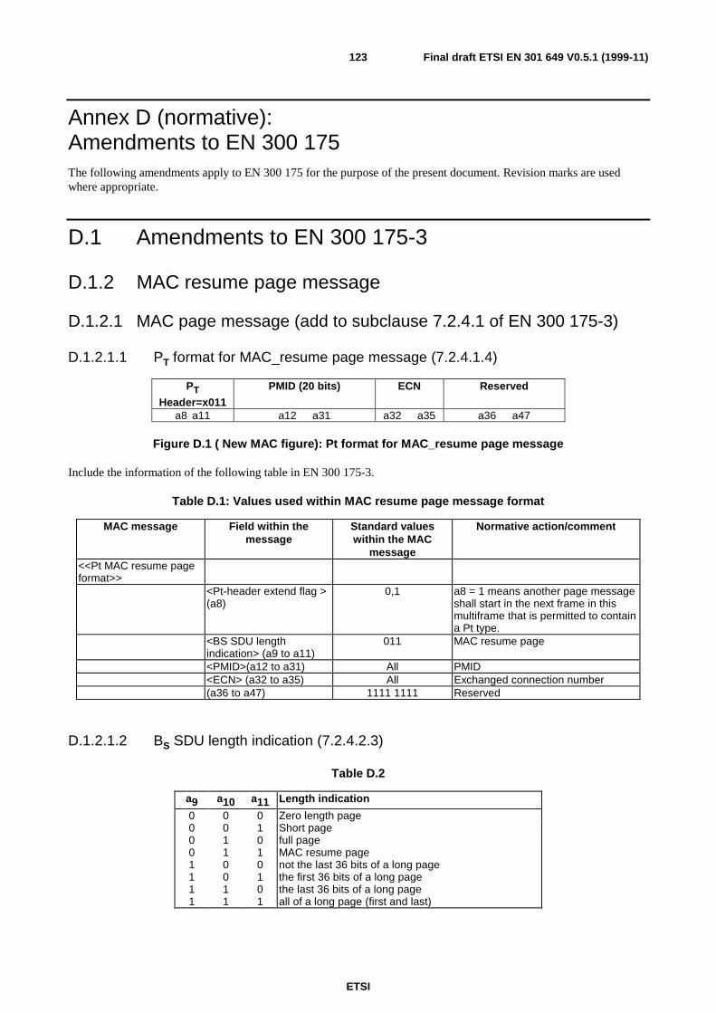
ETSI
Final draft ETSI EN 301 649 V0.5.1 (1999-11)123
Annex D (normative):Amendments to EN 300 175The following amendments apply to EN 300 175 for the purpose of the present document. Revision marks are usedwhere appropriate.
D.1 Amendments to EN 300 175-3
D.1.2 MAC resume page message
D.1.2.1 MAC page message (add to subclause 7.2.4.1 of EN 300 175-3)
D.1.2.1.1 PT format for MAC_resume page message (7.2.4.1.4)
PTHeader=x011
PMID (20 bits) ECN Reserved
a8 a11 a12 a31 a32 a35 a36 a47
Figure D.1 ( New MAC figure): Pt format for MAC_resume page message
Include the information of the following table in EN 300 175-3.
Table D.1: Values used within MAC resume page message format
MAC message Field within themessage
Standard valueswithin the MAC
message
Normative action/comment
<<Pt MAC resume pageformat>>
<Pt-header extend flag >(a8)
0,1 a8 = 1 means another page messageshall start in the next frame in thismultiframe that is permitted to containa Pt type.
<BS SDU lengthindication> (a9 to a11)
011 MAC resume page
<PMID>(a12 to a31) All PMID<ECN> (a32 to a35) All Exchanged connection number(a36 to a47) 1111 1111 Reserved
D.1.2.1.2 BS SDU length indication (7.2.4.2.3)
Table D.2
a9 a10 a11 Length indication
0 0 0 Zero length page0 0 1 Short page0 1 0 full page0 1 1 MAC resume page1 0 0 not the last 36 bits of a long page1 0 1 the first 36 bits of a long page1 1 0 the last 36 bits of a long page1 1 1 all of a long page (first and last)
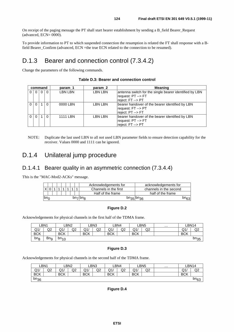
ETSI
Final draft ETSI EN 301 649 V0.5.1 (1999-11)124
On receipt of the paging message the PT shall start bearer establishment by sending a B_field Bearer_Request(advanced, ECN= 0000).
To provide information to PT to which suspended connection the resumption is related the FT shall response with a B-field Bearer_Confirm (advanced, ECN =the true ECN related to the connection to be resumed).
D.1.3 Bearer and connection control (7.3.4.2)Change the parameters of the following commands.
Table D.3: Bearer and connection control
command param_1 param_2 Meaning0 0 0 0 LBN LBN LBN LBN antenna switch for the single bearer identified by LBN
request: PT --> FTreject: FT --> PT
0 0 1 0 0000 LBN LBN LBN bearer handover of the bearer identified by LBNrequest: FT --> PTreject: PT --> FT
0 0 1 0 1111 LBN LBN LBN bearer handover of the bearer identified by LBNrequest: PT --> FTreject: FT --> PT
NOTE: Duplicate the last used LBN to all not used LBN parameter fields to ensure detection capability for thereceiver. Values 0000 and 1111 can be ignored.
D.1.4 Unilateral jump procedure
D.1.4.1 Bearer quality in an asymmetric connection (7.3.4.4)
This is the "MAC-Mod2-ACKs" message.
Acknowledgements for acknowledgements forX 0 1 1 1 1 1 1 Channels in the first channels in the second
Half of the frame half of the framebn0 bn7 bn8 bn35 bn36 bn63
Figure D.2
Acknowledgements for physical channels in the first half of the TDMA frame.
LBN1 LBN2 LBN3 LBN4 LBN5 … LBN14Q1/ Q2 Q1/ Q2 Q1/ Q2 Q1/ Q2 Q1/ Q2 Q1/ Q2BCK BCK BCK BCK BCK BCKbn8 Bn9 bn10 bn35
Figure D.3
Acknowledgements for physical channels in the second half of the TDMA frame.
LBN1 LBN2 LBN3 LBN4 LBN5 … LBN14Q1/ Q2 Q1/ Q2 Q1/ Q2 Q1/ Q2 Q1/ Q2 Q1/ Q2BCK BCK BCK BCK BCK BCKbn36 bn63
Figure D.4

ETSI
Final draft ETSI EN 301 649 V0.5.1 (1999-11)125
In pairs two bits are related to one simplex half of a double simplex bearer identified by the LBN. Depending on theMAC layer service the meaning of these bits is different.
For IN and IP_error_detection services the two bits have the function of the Q1 and Q2 bit. The setting of the Q1 and Q2
bit are described in the procedures of subclause 10.8.1.3.
For the IP_error_correction service the two bits have the function of the BCK and Q2 bit. The coding of these bits are
described in subclause 10.8.2.4.
D.1.4.2 General (10.6.1)
The MAC layer provides PTs and FTs with several mechanisms to control the quality of transmissions and receptions.Bearer handover may be initiated either by using this quality information or by receiving a bearer handover requestmessage from the far end (see subclauses 7.2.5.5 and 7.2.5). For duplex bearers the PT only can initiate a bearerhandover, and for double simplex bearers the transmitting side only can initiate a bearer handover. The existing bearercan be maintained until the new bearer has been established. During bearer handover the two bearers can operate inparallel.
NOTE 1: Bearer handover requires that an MBC for the connection exists on both sides, PT and FT, and that thenew selected RFP at the fixed side belongs to the same cluster.
PTs should use bearer handover to attempt to connect to the best RFP of the cluster in which the connection isestablished. This may be the same RFP as the existing bearer, or may be a new RFP.
DECT equipments may have several indicators to monitor reception quality:
• the A-field CRC;
• the X-field CRC;
• the CRCS of the B-subfields in protected mode (E-type or U-type for IP);
• X-field to Z-field comparison (for Z-field refer to EN 300 175-2 [2]);
• link identity information;
• synchronization pulse;
• clock jitter;
• signal strength.
To control the quality of transmissions the MAC layer uses the reports from the far end, coded in two bits:
• the (Q1,Q2) bits; or
• the (BCK,Q2) bits (see subclauses 7.1.1 and 7.3.4.4).
There are no specified rules for the PT which define when a bearer handover attempt has to be made. For system reasonsthe maximum rate at which bearer handovers can be performed is limited by a simple timer. No more than twosuccessful bearer handovers should occur within T202 seconds.
NOTE 2: This should not be confused with multiple attempts for one handover.
NOTE 3: For bearer handover (both intra- and inter-cell) in multibearer connections, each bearer is treatedseparately.
Different handover procedures exist for duplex and double simplex bearers.
ETSI
Final draft ETSI EN 301 649 V0.5.1 (1999-11)126
D.1.4.3 Q2 bit settings (10.8.1.3.1)
For duplex bearers the Q2 bit is the bit a7 of the A-field header. This bit is used for CS and CF-channel flow control and
may also be used to report bearer quality. The Q2 bit shall be set in response to the last received databurst on this bearer.
The quality of double simplex bearer shall be reported with the bearer quality control message defined insubclause 7.3.4.4. This message provides a Q2 bit for each simplex bearer. The location of the Q2 bits depends on thelogical bearer number (LBN). The Q2 bits reserved for established double simplex bearers shall be set according to thelast known quality results. The Q2 bits reserved for non-existing double simplex bearers shall be set to "0".
NOTE 1: No C-channel data is transmitted on double simplex bearers.
NOTE 2: For double simplex bearers the bit a7 of the A-field header is always set to 0.
NOTE 3: During bearer handover of a double simplex bearer the values of the Q2 bits for this logical bearer shouldbe ignored.
Rules for Q2 bit setting:
a) the Q2 bit is set to "0" whenever the A-field CRC failed. If the A-field CRC passes the Q2 bit setting isdetermined by the rules b) or c);
b) when a set of CF segments was received (correct A-field and BA bits indicate E-type with CF) the Q2 bit setting
depends on the CF data only. Setting the bit to "1" indicates an acknowledgement for this set of CF data (duplex
bearer only);
c) if the B-field contains an IP segment the Q2 bit shall be set to "1";
d) if the B-field contains an IN segment or only MAC control (see BA bit setting in the A-field header) the Q2 bit
setting depends on the transmission direction:
d.1) Data from FT to PT, Q2 from PT to FT: The Q2 bit shall be set to "1";
d.2) Data from PT to FT, Q2 from FT to PT: The Q2 bit may either be set to "1" or report if the B-field datawere accepted. In the latter case the Q2 bit shall be set to "1" for accepted B-field data and to "0" forrejected B-field data. It is the manufacturer's freedom to define the rules for accepting B-field data.
Notes to rule d.2):
NOTE 4: Manufacturers should set the Q2 bit according to B-field data acceptance. This option enables PTs toinitiate a bearer handover whenever the bearer quality is bad. Tests may be based e.g. on the X-field CRCresult or on RB CRC results of B-subfields if MAC control was received.
NOTE 5: Q2 set to "1" is also an acknowledgement for received CS data (duplex bearers only). If the setting of the
Q2 bit depends on the acceptance of B-field data the Q1 bit setting option to report the A-field CRC resultshould also be applied. Otherwise the CS data throughput may suffer.
ETSI
Final draft ETSI EN 301 649 V0.5.1 (1999-11)127
D.1.4.4 MOD-2 protected I-channel operation (IP) (10.8.2)
D.1.4.4.1 General (10.8.2.1)
The modulo-2 procedure uses a 2-state packet number in the A-field header. This packet number applies to the completeB-field of IP data. The first IP packet sent on a new logical bearer is labelled with packet number "1".
Successful reception of the data is acknowledged independently for each logical bearer. For duplex bearers theacknowledgement mechanism uses the Q2 and the BCK bits in the return A-field header. For double simplex bearers,these bits, the Q2 and BCK bits, for each logical simplex bearer are multiplexed into a "MAC-MOD2-ACKS" message,and this message is sent in at least one B-subfield on at least one reverse bearer.
MOD-2 operation in the asymmetric case shall use the E32-mux or the E80-mux in the reverse direction.
NOTE: The MOD-2 receiver may use selective reception, or even majority voting to achieve CRC success.
D.1.4.4.2 Use of the acknowledge bits (10.8.2.4)
During MOD-2 operation two bits are used for IP-channel flow control. These bits are located in different positions for
duplex and double simplex bearers. The two bits are:
• the Q2 bit and the BCK bit in the A-field header at positions a3 and a7 as described in subclause 7.1 for a duplex
bearer;
• two pairs of an Q2 and a BCK bit in the quality control message described in subclause 7.3.4.4 for a doublesimplex bearer.
The settings of the Q2 bit is described in subclause 10.8.2.4.1.
The setting of the BCK bit is described in subclause 10.8.2.4.2.
The two control bits Q2 and BCK in the A-field shall be set individually for each duplex bearer of a symmetric or anasymmetric connection.
The two control bits Q2 and BCK in the quality control message shall be set individually for each logical half of adouble simplex bearer in asymmetric connections. The Q2 bits for non-existing logical double simplex bearers shall beset to "0" and the BCK bits to "1".
During bearer handover of a double simplex bearer, the acknowledge results for the old and the new bearer (bearers withthe same LBN) should be combined to produce a single set of results.
NOTE: It is not allowed to transmit two different IP segments in the same TDMA half frame on the "new" and the
"old" double simplex bearer during bearer handover (see subclause 10.6.3).
D.1.4.4.3 Q2 bit setting for IP_error_correction services (10.8.2.4.1)
Q2 bit setting for duplex bearer
The Q2 bit setting influences the retransmission mechanism from CS, CF and IP data. The setting of the Q2 bit is exactly
the same as in IP_error_detection services (see subclause 10.8.1.3.1).
NOTE 1: When an IP segment was received (A-field CRC correct and the BA bits set to IP segment with number 0
or 1) the Q2 bit is set to "1", regardless of the results of the B-field CRCs. The MOD-2 retransmissionscheme assumes for proper operation, that the packet number of the IP segment is then known to the IP
data receiver.
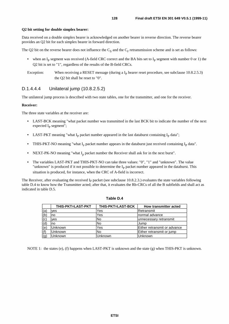
ETSI
Final draft ETSI EN 301 649 V0.5.1 (1999-11)128
Q2 bit setting for double simplex bearer:
Data received on a double simplex bearer is acknowledged on another bearer in reverse direction. The reverse bearerprovides an Q2 bit for each simplex bearer in forward direction.
The Q2 bit on the reverse bearer does not influence the CS and the CF retransmission scheme and is set as follows:
• when an IP segment was received (A-field CRC correct and the BA bits set to IP segment with number 0 or 1) the
Q2 bit is set to "1", regardless of the results of the B-field CRCs.
Exception: When receiving a RESET message (during a IP bearer reset procedure, see subclause 10.8.2.5.3)
the Q2 bit shall be reset to "0".
D.1.4.4.4 Unilateral jump (10.8.2.5.2)
The unilateral jump process is described with two state tables, one for the transmitter, and one for the receiver.
Receiver:
The three state variables at the receiver are:
• LAST-BCK meaning "what packet number was transmitted in the last BCK bit to indicate the number of the nextexpected IP segment";
• LAST-PKT meaning "what IP packet number appeared in the last databurst containing IP data";
• THIS-PKT-NO meaning "what IP packet number appears in the databurst just received containing IP data".
• NEXT-PK-NO meaning "what Ip packet number the Receiver shall ask for in the next burst".
• The variables LAST-PKT and THIS-PKT-NO can take three values: "0", "1" and "unknown". The value"unknown" is produced if it not possible to determine the IP packet number appeared in the databurst. This
situation is produced, for instance, when the CRC of A-field is incorrect.
The Receiver, after evaluating the received Ip packet (see subclause 10.8.2.3.) evaluates the state variables followingtable D.4 to know how the Transmitter acted; after that, it evaluates the Rb-CRCs of all the B subfields and shall act asindicated in table D.5.
Table D.4
THIS-PKT=LAST-PKT THIS-PKT=LAST-BCK How transmitter acted(a) yes Yes Retransmit(b) no Yes normal advance(c) yes No unnecessary retransmit(d) no No Jump(e) Unknown Yes Either retransmit or advance(f) Unknown No Either retransmit or jump(g) Unknown Unknown Unknown
NOTE 1: the states (e), (f) happens when LAST-PKT is unknown and the state (g) when THIS-PKT is unknown.

ETSI
Final draft ETSI EN 301 649 V0.5.1 (1999-11)129
Table D.5
Table D.4 state Rb-CRC result how Receiver shall act(g) Not considered NEXT-BCK = LAST-BCK
(a), (b), (e) Rb-CRCs passed NEXT-BCK = LAST-BCK + 1 (MOD 2)(a), (b), (e) Rb-CRCs failed NEXT-BCK = LAST-BCK
(c) Rb-CRCs passed NEXT-BCK = LAST-BCK; RX still requires the sameIP packet
(c) Rb-CRCs failed NEXT-BCK = LAST-BCK; RX still requires the sameIP packet
(d), (f) Rb-CRCs passed NEXT-BCK = LAST-BCK(d), (f) Rb-CRCs failed NEXT-BCK = LAST-BCK + 1 (MOD 2)
NOTE 2: In cases (e) and (f), the receiver can not be sure what was the action in the TX side. In these cases thepacket should be delivered to the DLC layer.
Transmitter:
Define: LTIP = packet number of the last transmitted IP segment.
The two state variables at the transmitter are:
• ACKN meaning "an IP packet has been received in the receiver last databurst":
• for duplex bearer the reception of the IP packet is acknowledged by receiving an A-field correct and with the
Q2 bit set to 1 (see subclause 10.8.2.4.1);
• for double simplex bearer the reception of the IP packet is acknowledged by receiving an A-field correct and
with Q1 bit set to 1 (see subclause 10.8.2.4.1).
NOTE 3: For double simplex bearer this process is independent for both simplex bearers.
• LAST-BCK meaning "what was the setting of the last correct received BCK bit (with the BCK bit the receiverreports the next expected IP packet)?".
NOTE 4: If ACKN switches to "yes" also a new BCK is received.
Table D.6
ACKN LTIP = LAST-BCK How transmitter shall act
(a) Yes No normal advance (or retransmit)(b) Yes Yes retransmit or jump(c) No No retransmit or jump(d) No Yes retransmit or jump
The transmitter shall use the jump procedure when the packet limit lifetime expires.
In state (b) the transmitter can choose between retransmission and jump. Its choice is reflected in the pkt number chosen.If jump the pkt number toggles if retransmit the pkt number is unchanged.
D.1.5 Bearer ReplacementNOTE: It is proposed to change current subclause 10.6.4 Frequency Replacement into Bearer Replacement and to
have two subclauses, general bearer replacement and as a special case of bearer replacement the Frequencyreplacement procedure.
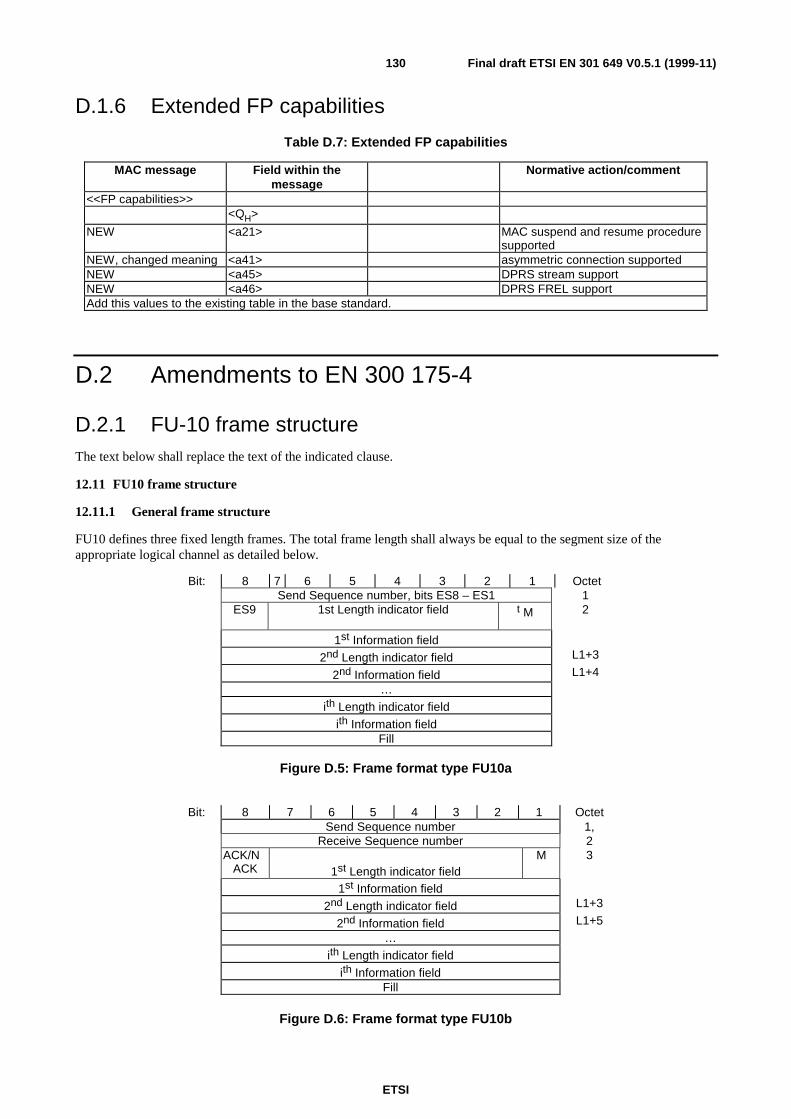
ETSI
Final draft ETSI EN 301 649 V0.5.1 (1999-11)130
D.1.6 Extended FP capabilities
Table D.7: Extended FP capabilities
MAC message Field within themessage
Normative action/comment
<<FP capabilities>><QH>
NEW <a21> MAC suspend and resume proceduresupported
NEW, changed meaning <a41> asymmetric connection supportedNEW <a45> DPRS stream supportNEW <a46> DPRS FREL supportAdd this values to the existing table in the base standard.
D.2 Amendments to EN 300 175-4
D.2.1 FU-10 frame structureThe text below shall replace the text of the indicated clause.
12.11 FU10 frame structure
12.11.1 General frame structure
FU10 defines three fixed length frames. The total frame length shall always be equal to the segment size of theappropriate logical channel as detailed below.
Bit: 8 7 6 5 4 3 2 1 OctetSend Sequence number, bits ES8 – ES1 1
ES9 1st Length indicator field t M 2
1st Information field
2nd Length indicator field L1+3
2nd Information field L1+4
…
ith Length indicator field
ith Information fieldFill
Figure D.5: Frame format type FU10a
Bit: 8 7 6 5 4 3 2 1 OctetSend Sequence number 1,
Receive Sequence number 2ACK/N
ACK 1st Length indicator fieldM 3
1st Information field
2nd Length indicator field L1+3
2nd Information field L1+5
…
ith Length indicator field
ith Information fieldFill
Figure D.6: Frame format type FU10b
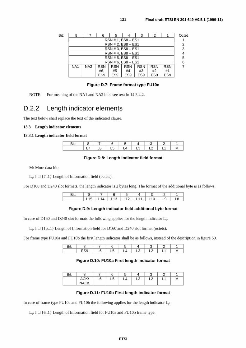
ETSI
Final draft ETSI EN 301 649 V0.5.1 (1999-11)131
Bit: 8 7 6 5 4 3 2 1 OctetRSN # 1, ES8 – ES1 1RSN # 2, ES8 – ES1 2RSN # 3, ES8 – ES1 3RSN # 4, ES8 – ES1 4RSN # 5, ES8 – ES1 5RSN # 6, ES8 – ES1 6
NA1 NA2 RSN#6,ES9
RSN#5
ES9
RSN#4
ES9
RSN#3
ES9
RSN#2
ES9
RSN#1
ES9
7
Figure D.7: Frame format type FU10c
NOTE: For meaning of the NA1 and NA2 bits: see text in 14.3.4.2.
D.2.2 Length indicator elementsThe text below shall replace the text of the indicated clause.
13.3 Length indicator elements
13.3.1 Length indicator field format
Bit: 8 7 6 5 4 3 2 1L7 L6 L5 L4 L3 L2 L1 M
Figure D.8: Length indicator field format
M: More data bit;
LI: I ∈ {7..1} Length of Information field (octets).
For D160 and D240 slot formats, the length indicator is 2 bytes long. The format of the additional byte is as follows.
Bit: 8 7 6 5 4 3 2 1L15 L14 L13 L12 L11 L10 L9 L8
Figure D.9: Length indicator field additional byte format
In case of D160 and D240 slot formats the following applies for the length indicator LI:
LI: I ∈ {15..1} Length of Information field for D160 and D240 slot format (octets).
For frame type FU10a and FU10b the first length indicator shall be as follows, instead of the description in figure 59.
Bit: 8 7 6 5 4 3 2 1ES9 L6 L5 L4 L3 L2 L1 M
Figure D.10: FU10a First length indicator format
Bit: 8 7 6 5 4 3 2 1ACK/NACK
L6 L5 L4 L3 L2 L1 M
Figure D.11: FU10b First length indicator format
In case of frame type FU10a and FU10b the following applies for the length indicator LI:
LI: I ∈ {6..1} Length of Information field for FU10a and FU10b frame type.

ETSI
Final draft ETSI EN 301 649 V0.5.1 (1999-11)132
In case of frame type FU10a the following applies:
The Send sequence number is extended with bitES9 of the 1st length indicator field. In all other length indicator fieldsthis bit shall be ignored.
13.3.2 Length indicator field parameters
Extended more data bit M: the extended more data bit, M, is used to indicate segmentation of messages into FUxframes.
M = "1" indicates that the information field only contains part of a message - there is more to follow.
M = "0" indicates one of two things:
a) that the information field contains a complete message, provided that the M bit of the previous frame was alsoset to "0";
b) that the information field contains the last segment of a message, provided that the M bit of the previousframe was set to "1".
When the M bit is set to "1", the information field should contain the maximum number of octets.
NOTE 1: This rule only recommends that each frame contains the maximum amount of information. However, theLI field always defines the actual length.
When using frame type FU10a or FU10b a M bit set to "0" means additionally, that the next M bit within this PDU hasto be examined, if more data of a further SDU follows in this PDU.
To indicate that there is no data of a further SDU following within the current PDU, both the M bit and LI shall be set to
"0".
Length parameter LI: the length parameter LI consists of 7 bits for all slot formats except for D160 and D240 and except
the FU10 frame format. For D160 and D240 slot formats, the length parameter LI consists of 15 bits. For FU10 the
length parameter consists of 6 bits. The length parameter LI defines the length of the information field in all frames.
Allowable values for 2 level modulated full slot formats are:
• 0 to 30 for frame types FU2, FU6a and FU10a;
• 0 to 29 for frame types FU4a and FU10b;
• 0 to 28 for frame types FU5a.
NOTE 2: Maximum value for full slot is 30 octets. 7 bits are allowed for possible double slot D80 operation -100 octets. For D160 and D240 operation, 7 bits are not enough and hence 2 octets are required for theLength Indicator field.
LI = "0" is used for all frames that contain no higher layer information.
NOTE 3: Frames that contain no higher layer information should not be transmitted.
Remaining (unused) octets shall be filled with the standard fill octet defined in subclause 13.5.
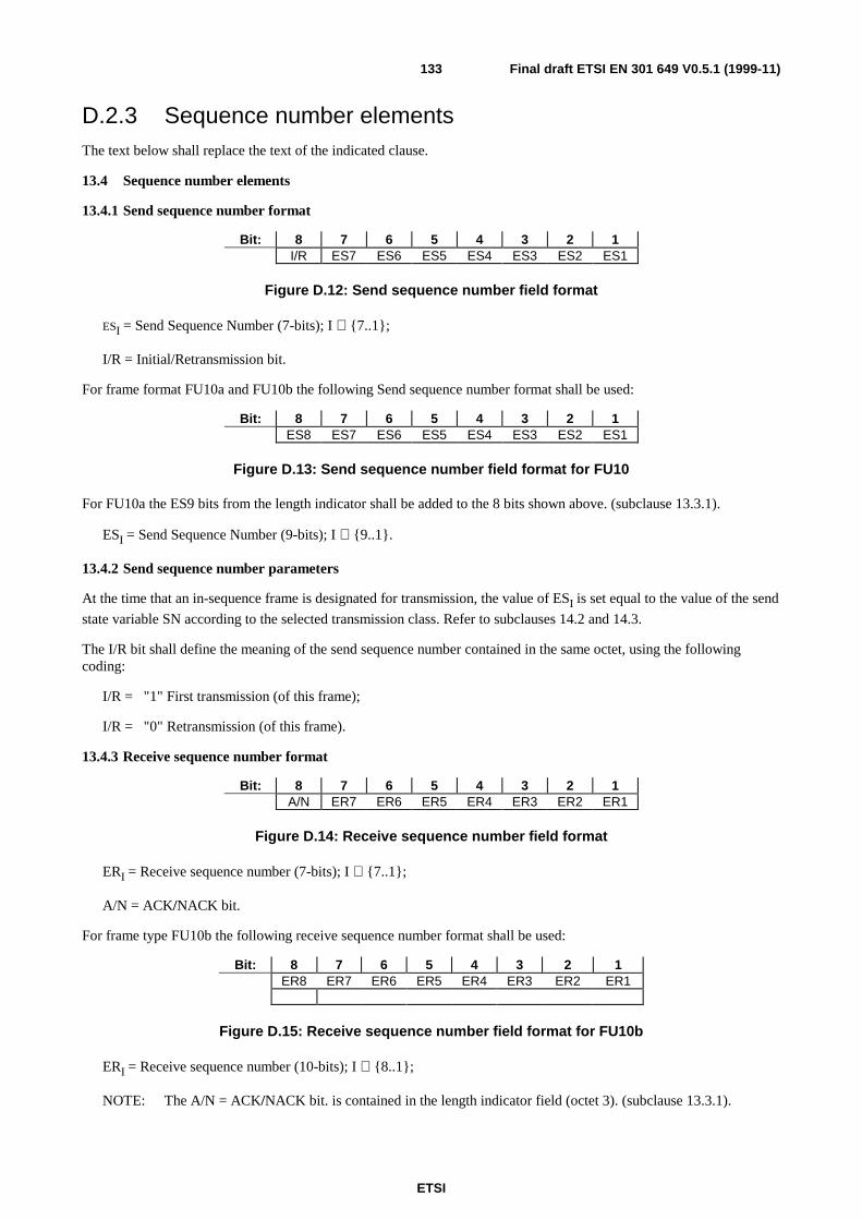
ETSI
Final draft ETSI EN 301 649 V0.5.1 (1999-11)133
D.2.3 Sequence number elementsThe text below shall replace the text of the indicated clause.
13.4 Sequence number elements
13.4.1 Send sequence number format
Bit: 8 7 6 5 4 3 2 1I/R ES7 ES6 ES5 ES4 ES3 ES2 ES1
Figure D.12: Send sequence number field format
ESI = Send Sequence Number (7-bits); I ∈ {7..1};
I/R = Initial/Retransmission bit.
For frame format FU10a and FU10b the following Send sequence number format shall be used:
Bit: 8 7 6 5 4 3 2 1ES8 ES7 ES6 ES5 ES4 ES3 ES2 ES1
Figure D.13: Send sequence number field format for FU10
For FU10a the ES9 bits from the length indicator shall be added to the 8 bits shown above. (subclause 13.3.1).
ESI = Send Sequence Number (9-bits); I ∈ {9..1}.
13.4.2 Send sequence number parameters
At the time that an in-sequence frame is designated for transmission, the value of ESI is set equal to the value of the send
state variable SN according to the selected transmission class. Refer to subclauses 14.2 and 14.3.
The I/R bit shall define the meaning of the send sequence number contained in the same octet, using the followingcoding:
I/R = "1" First transmission (of this frame);
I/R = "0" Retransmission (of this frame).
13.4.3 Receive sequence number format
Bit: 8 7 6 5 4 3 2 1A/N ER7 ER6 ER5 ER4 ER3 ER2 ER1
Figure D.14: Receive sequence number field format
ERI = Receive sequence number (7-bits); I ∈ {7..1};
A/N = ACK/NACK bit.
For frame type FU10b the following receive sequence number format shall be used:
Bit: 8 7 6 5 4 3 2 1ER8 ER7 ER6 ER5 ER4 ER3 ER2 ER1
Figure D.15: Receive sequence number field format for FU10b
ERI = Receive sequence number (10-bits); I ∈ {8..1};
NOTE: The A/N = ACK/NACK bit. is contained in the length indicator field (octet 3). (subclause 13.3.1).
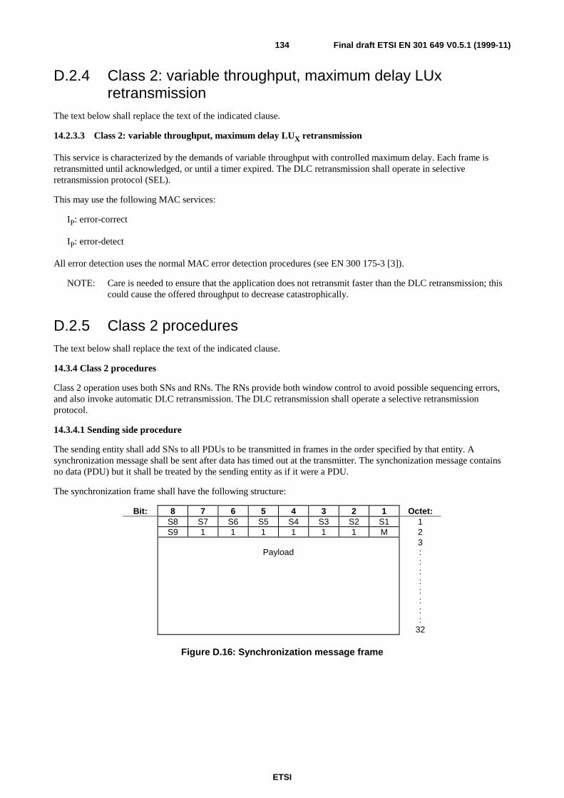
ETSI
Final draft ETSI EN 301 649 V0.5.1 (1999-11)134
D.2.4 Class 2: variable throughput, maximum delay LUxretransmission
The text below shall replace the text of the indicated clause.
14.2.3.3 Class 2: variable throughput, maximum delay LUX retransmission
This service is characterized by the demands of variable throughput with controlled maximum delay. Each frame isretransmitted until acknowledged, or until a timer expired. The DLC retransmission shall operate in selectiveretransmission protocol (SEL).
This may use the following MAC services:
IP: error-correct
IP: error-detect
All error detection uses the normal MAC error detection procedures (see EN 300 175-3 [3]).
NOTE: Care is needed to ensure that the application does not retransmit faster than the DLC retransmission; thiscould cause the offered throughput to decrease catastrophically.
D.2.5 Class 2 proceduresThe text below shall replace the text of the indicated clause.
14.3.4 Class 2 procedures
Class 2 operation uses both SNs and RNs. The RNs provide both window control to avoid possible sequencing errors,and also invoke automatic DLC retransmission. The DLC retransmission shall operate a selective retransmissionprotocol.
14.3.4.1 Sending side procedure
The sending entity shall add SNs to all PDUs to be transmitted in frames in the order specified by that entity. Asynchronization message shall be sent after data has timed out at the transmitter. The synchonization message containsno data (PDU) but it shall be treated by the sending entity as if it were a PDU.
The synchronization frame shall have the following structure:
Bit: 8 7 6 5 4 3 2 1 Octet:S8 S7 S6 S5 S4 S3 S2 S1 1S9 1 1 1 1 1 1 M 2
Payload3::::::::
32
Figure D.16: Synchronization message frame
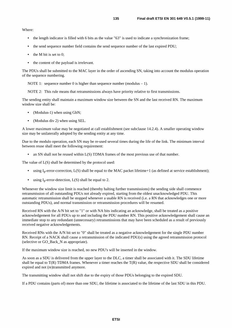
ETSI
Final draft ETSI EN 301 649 V0.5.1 (1999-11)135
Where:
• the length indicator is filled with 6 bits as the value "63" is used to indicate a synchronization frame;
• the send sequence number field contains the send sequence number of the last expired PDU;
• the M bit is set to 0;
• the content of the payload is irrelevant.
The PDUs shall be submitted to the MAC layer in the order of ascending SN, taking into account the modulus operationof the sequence numbering.
NOTE 1: sequence number 0 is higher than sequence number (modulus – 1).
NOTE 2: This rule means that retransmissions always have priority relative to first transmissions.
The sending entity shall maintain a maximum window size between the SN and the last received RN. The maximumwindow size shall be:
• (Modulus-1) when using GbN;
• (Modulus div 2) when using SEL.
A lower maximum value may be negotiated at call establishment (see subclause 14.2.4). A smaller operating windowsize may be unilaterally adopted by the sending entity at any time.
Due to the modulo operation, each SN may be re-used several times during the life of the link. The minimum intervalbetween reuse shall meet the following requirement:
• an SN shall not be reused within L(S) TDMA frames of the most previous use of that number.
The value of L(S) shall be determined by the protocol used:
• using IP-error-correction, L(S) shall be equal to the MAC packet lifetime+1 (as defined at service establishment);
• using IP-error-detection, L(S) shall be equal to 2.
Whenever the window size limit is reached (thereby halting further transmissions) the sending side shall commenceretransmission of all outstanding PDUs not already expired, starting from the oldest unacknowledged PDU. Thisautomatic retransmission shall be stopped whenever a usable RN is received (i.e. a RN that acknowledges one or moreoutstanding PDUs), and normal transmission or retransmission procedures will be resumed.
Received RN with the A/N bit set to "1" or with NA bits indicating an acknowledge, shall be treated as a positiveacknowledgement for all PDUs up to and including the PDU number RN. This positive acknowledgement shall cause animmediate stop to any redundant (unnecessary) retransmissions that may have been scheduled as a result of previouslyreceived negative acknowledgements.
Received RNs with the A/N bit set to "0" shall be treated as a negative acknowledgement for the single PDU numberRN. Receipt of a NACK shall cause a retransmission of the indicated PDU(s) using the agreed retransmission protocol(selective or GO_Back_N as appropriate).
If the maximum window size is reached, no new PDU's will be inserted in the window.
As soon as a SDU is delivered from the upper layer to the DLC, a timer shall be associated with it. The SDU lifetimeshall be equal to T(R) TDMA frames. Whenever a timer reaches the T(R) value, the respective SDU shall be consideredexpired and not (re)transmitted anymore.
The transmitting window shall not shift due to the expiry of those PDUs belonging to the expired SDU.
If a PDU contains (parts of) more than one SDU, the lifetime is associated to the lifetime of the last SDU in this PDU.
ETSI
Final draft ETSI EN 301 649 V0.5.1 (1999-11)136
The lifetime limit should be defined at call establishment and shall not be subsequently changed. If the lifetime limit isnot specified at call establishment the following value shall apply:
• T(R) = infinite TDMA frames.
NOTE 3: When a PDU is about to be discarded due to lifetime expiry then the transmitter may re-transmit this PDUin an attempt to prevent data loss.
NOTE 4: The value T(R) should normally be negotiated with the <<transit-delay>> element during callestablishment (see EN 300 175-5 [5]).
During the lifetime the transmitter may retransmit the PDU. Retransmissions shall be stopped when the PDU isacknowledged.
When one or more PDUs expire, then the last expired PDU shall be replaced by the synchronization message. Thesynchronization message shall contain the sequence number of this PDU.
NOTE 5: Expiry of all PDUs in the transmit window will cause a re-transmit of the synchronization message only,until acknowledge. Then the transmit window can advance and take new PDUs.
Acknowledge of the synchronization message shall use a special synchronization acknowledge to indicate the correctreception of the synchronization message. When the transmitter receives this acknowledge, it knows the receiver has re-synchronized its window and the transmitter is also allowed to move the transmit window forward, accepting new PDUsfor transmission.
14.3.4.2 Receiving side procedure
The receiving entity shall accept data packets from the MAC layer in any order. Packets marked as type "unknown" andany packets that are indicated to contain errors shall be discarded. The remaining packets shall be assumed to containvalid PDUs, and shall be processed in their order of arrival. PDUs with sequence number outside the receive windowshall be discarded. Only a synchronization message shall be accepted always, even if the sequence number is outside thereceive window. Duplicate PDUs shall also be discarded.
NOTE 6: Discarded valid PDUs should preferably be acknowledged to prevent unnecessary retransmissions, byretransmitting the last acknowledge.
In-sequence PDUs are defined as a series of one or more PDUs that contain no errors and that contain SN(s) thattogether form a continuous series of SNs when considered together with other received but undelivered PDUs. All in-sequence PDUs shall immediately be delivered to the higher functions and acknowledged.
As soon as a synchronization message has been received, the RN shall be set to one higher than the value of the SNcontained in the synchronization message and all the buffered PDUs with an SN lower than or equal to the received oneshould be discarded.
NOTE 7: Discarding these PDUs guarantees the maximum lifetime. Synchronization indicates their lifetime hasexpired.
The re-synchronization shall be sent to higher functions to indicate a discontinuity in PDU numbering.
NOTE 8: Actual numbering might be continuous due to the modulo numbering scheme.
The synchronization message shall always be acknowledged using a special synchronization acknowledge, in order toindicate that the transmitter can advance its window. The synchronization acknowledge can have two formats,depending on the connection type:
• symmetric connection uses the same format as the synchronization message for the synchronization acknowledge:the Length Indicator has value 63 and the sequence number of the synchonization message is returned;
• asymmetric connection uses the Gf-channel ACK/NACK message with a special coding for NA1 and NA2 bits =0,0 as shown below.
ETSI
Final draft ETSI EN 301 649 V0.5.1 (1999-11)137
Bit: 8 7 6 5 4 3 2 1 OctetRSN # 1, ES8 – ES1 1RSN # 2, ES8 – ES1 2RSN # 3, ES8 – ES1 3RSN # 4, ES8 – ES1 4RSN # 5, ES8 – ES1 5RSN # 6, ES8 – ES1 6
NA1 NA2 RSN#6,ES9
RSN#5
ES9
RSN#4
ES9
RSN#3
ES9
RSN#2
ES9
RSN#1
ES9
7
Figure D.17: Frame FU10c for slot type D32, 9 Bit sequence numbering
The interpretation of the RSNs as either ACKs or NACKs is indicated by bits NA1 and NA2.
Bit NA1 NA2 Meaning0 0 this frame contains an Ack of a synchronization message in RSN#1, no NACKs0 1 this frame contains only one ACK message in RSN#1, no NACKs1 0 this frame contains one ACK message in RSN#1plus five NACK messages in RSN#2-RSN#61 1 this frame contains six NACK messages
Out-of-sequence PDUs are defined as all other PDUs (i.e. a sequence of one or more PDUs that do not form acontinuous series of SNs or contain some errors).
If after buffering for L(R) TDMA frames, out-of-sequence remains out-of-sequence, the receiving entity shouldreturn acomposed NACK message.
After that, as long as the out-of-sequence PDUs remain out-of-sequence, they shall continue to be buffered and at mostone composed NACK message maybe sent in any period of L(R) TDMA frames.
Out-of-sequence PDUs may become in-sequence PDUs due to the arrival of one or more of the missing PDUs. In thisevent, the PDUs shall immediately be delivered to the higher functions.
For the GBN protocol a NACK shall carry a single value of RN, set equal to the lowest numbered missing PDU. For theSEL protocol, multiple RN values shall be returned; one for each missing PDU.
NOTE 9: Out of sequence PDUs may be discarded during this buffer period, in order to limit buffer sizes.
The value of L(R), shall be determined by the service used:
• when using the IP-error-correction protocol:
L(R)=( MAC packet lifetime+1);
• When using the IP-error-detection protocol:
L(R)=1 TDMA frames;
Whenever PDUs are delivered to the higher functions, the RN for all positive acknowledgements shall be set equal tothe highest delivered SN + 1.
D.2.6 LU10 Enhanced Frame RELay (EFREL) Service11.12 LU10 Enhanced Frame RELay (EFREL) Service
11.12.1 General
The LU10 is a general data transmission service for medium data rates, high error correction performance and lowcomplexity. LU10 provides a peer-to-peer connection protocol for an acknowledged exchange of user data within theDLC_U-Layer.
For LU10 the use of ARQ-type SEL is recommended. Go_Back_N is also allowed.
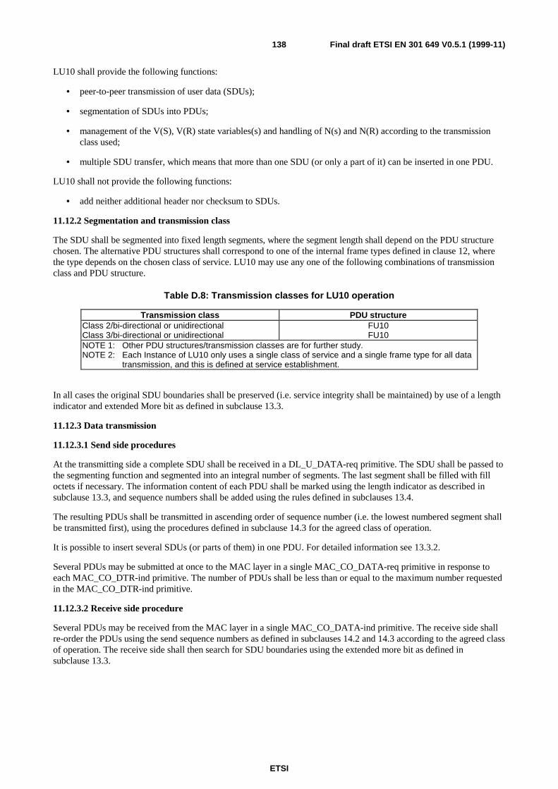
ETSI
Final draft ETSI EN 301 649 V0.5.1 (1999-11)138
LU10 shall provide the following functions:
• peer-to-peer transmission of user data (SDUs);
• segmentation of SDUs into PDUs;
• management of the V(S), V(R) state variables(s) and handling of N(s) and N(R) according to the transmissionclass used;
• multiple SDU transfer, which means that more than one SDU (or only a part of it) can be inserted in one PDU.
LU10 shall not provide the following functions:
• add neither additional header nor checksum to SDUs.
11.12.2 Segmentation and transmission class
The SDU shall be segmented into fixed length segments, where the segment length shall depend on the PDU structurechosen. The alternative PDU structures shall correspond to one of the internal frame types defined in clause 12, wherethe type depends on the chosen class of service. LU10 may use any one of the following combinations of transmissionclass and PDU structure.
Table D.8: Transmission classes for LU10 operation
Transmission class PDU structureClass 2/bi-directional or unidirectionalClass 3/bi-directional or unidirectional
FU10FU10
NOTE 1: Other PDU structures/transmission classes are for further study.NOTE 2: Each Instance of LU10 only uses a single class of service and a single frame type for all data
transmission, and this is defined at service establishment.
In all cases the original SDU boundaries shall be preserved (i.e. service integrity shall be maintained) by use of a lengthindicator and extended More bit as defined in subclause 13.3.
11.12.3 Data transmission
11.12.3.1 Send side procedures
At the transmitting side a complete SDU shall be received in a DL_U_DATA-req primitive. The SDU shall be passed tothe segmenting function and segmented into an integral number of segments. The last segment shall be filled with filloctets if necessary. The information content of each PDU shall be marked using the length indicator as described insubclause 13.3, and sequence numbers shall be added using the rules defined in subclauses 13.4.
The resulting PDUs shall be transmitted in ascending order of sequence number (i.e. the lowest numbered segment shallbe transmitted first), using the procedures defined in subclause 14.3 for the agreed class of operation.
It is possible to insert several SDUs (or parts of them) in one PDU. For detailed information see 13.3.2.
Several PDUs may be submitted at once to the MAC layer in a single MAC_CO_DATA-req primitive in response toeach MAC_CO_DTR-ind primitive. The number of PDUs shall be less than or equal to the maximum number requestedin the MAC_CO_DTR-ind primitive.
11.12.3.2 Receive side procedure
Several PDUs may be received from the MAC layer in a single MAC_CO_DATA-ind primitive. The receive side shallre-order the PDUs using the send sequence numbers as defined in subclauses 14.2 and 14.3 according to the agreed classof operation. The receive side shall then search for SDU boundaries using the extended more bit as defined insubclause 13.3.
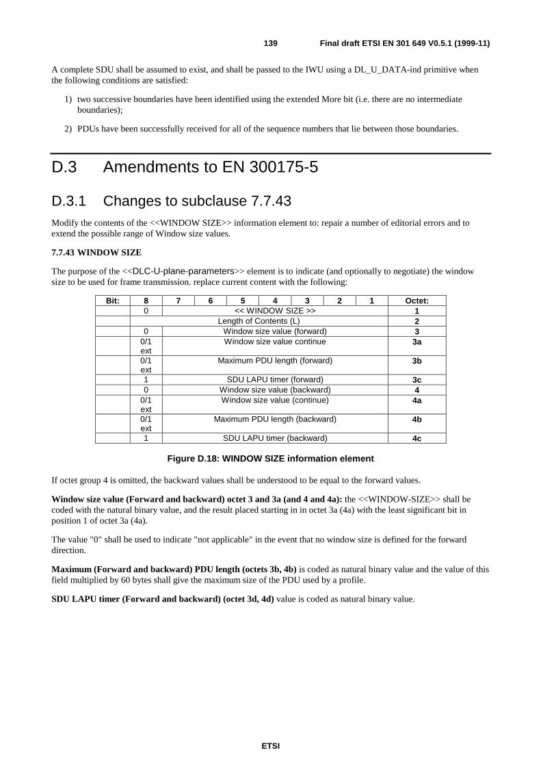
ETSI
Final draft ETSI EN 301 649 V0.5.1 (1999-11)139
A complete SDU shall be assumed to exist, and shall be passed to the IWU using a DL_U_DATA-ind primitive whenthe following conditions are satisfied:
1) two successive boundaries have been identified using the extended More bit (i.e. there are no intermediateboundaries);
2) PDUs have been successfully received for all of the sequence numbers that lie between those boundaries.
D.3 Amendments to EN 300175-5
D.3.1 Changes to subclause 7.7.43Modify the contents of the <<WINDOW SIZE>> information element to: repair a number of editorial errors and toextend the possible range of Window size values.
7.7.43 WINDOW SIZE
The purpose of the <<DLC-U-plane-parameters>> element is to indicate (and optionally to negotiate) the windowsize to be used for frame transmission. replace current content with the following:
Bit: 8 7 6 5 4 3 2 1 Octet:0 << WINDOW SIZE >> 1
Length of Contents (L) 20 Window size value (forward) 3
0/1ext
Window size value continue 3a
0/1ext
Maximum PDU length (forward) 3b
1 SDU LAPU timer (forward) 3c0 Window size value (backward) 4
0/1ext
Window size value (continue) 4a
0/1ext
Maximum PDU length (backward) 4b
1 SDU LAPU timer (backward) 4c
Figure D.18: WINDOW SIZE information element
If octet group 4 is omitted, the backward values shall be understood to be equal to the forward values.
Window size value (Forward and backward) octet 3 and 3a (and 4 and 4a): the <<WINDOW-SIZE>> shall becoded with the natural binary value, and the result placed starting in in octet 3a (4a) with the least significant bit inposition 1 of octet 3a (4a).
The value "0" shall be used to indicate "not applicable" in the event that no window size is defined for the forwarddirection.
Maximum (Forward and backward) PDU length (octets 3b, 4b) is coded as natural binary value and the value of thisfield multiplied by 60 bytes shall give the maximum size of the PDU used by a profile.
SDU LAPU timer (Forward and backward) (octet 3d, 4d) value is coded as natural binary value.
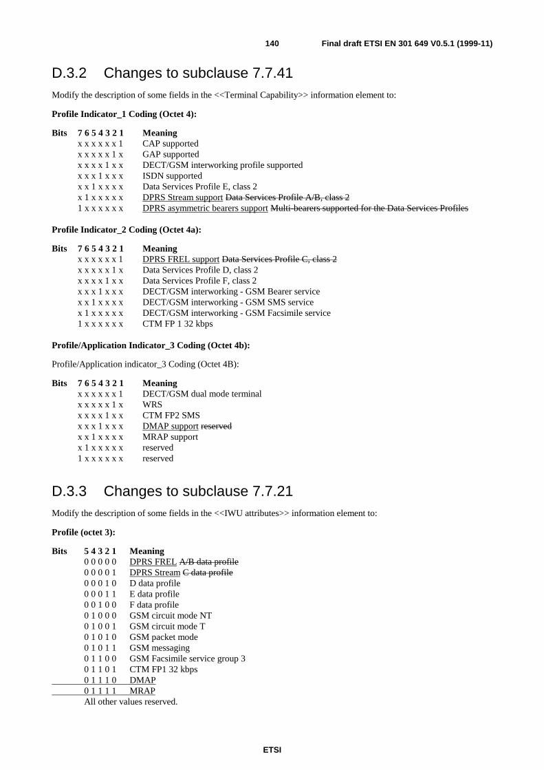
ETSI
Final draft ETSI EN 301 649 V0.5.1 (1999-11)140
D.3.2 Changes to subclause 7.7.41Modify the description of some fields in the <<Terminal Capability>> information element to:
Profile Indicator_1 Coding (Octet 4):
Bits 7 6 5 4 3 2 1 Meaningx x x x x x 1 CAP supportedx x x x x 1 x GAP supportedx x x x 1 x x DECT/GSM interworking profile supportedx x x 1 x x x ISDN supportedx x 1 x x x x Data Services Profile E, class 2x 1 x x x x x DPRS Stream support Data Services Profile A/B, class 21 x x x x x x DPRS asymmetric bearers support Multi-bearers supported for the Data Services Profiles
Profile Indicator_2 Coding (Octet 4a):
Bits 7 6 5 4 3 2 1 Meaningx x x x x x 1 DPRS FREL support Data Services Profile C, class 2x x x x x 1 x Data Services Profile D, class 2x x x x 1 x x Data Services Profile F, class 2x x x 1 x x x DECT/GSM interworking - GSM Bearer servicex x 1 x x x x DECT/GSM interworking - GSM SMS servicex 1 x x x x x DECT/GSM interworking - GSM Facsimile service1 x x x x x x CTM FP 1 32 kbps
Profile/Application Indicator_3 Coding (Octet 4b):
Profile/Application indicator_3 Coding (Octet 4B):
Bits 7 6 5 4 3 2 1 Meaningx x x x x x 1 DECT/GSM dual mode terminalx x x x x 1 x WRSx x x x 1 x x CTM FP2 SMSx x x 1 x x x DMAP support reservedx x 1 x x x x MRAP supportx 1 x x x x x reserved1 x x x x x x reserved
D.3.3 Changes to subclause 7.7.21Modify the description of some fields in the <<IWU attributes>> information element to:
Profile (octet 3):
Bits 5 4 3 2 1 Meaning0 0 0 0 0 DPRS FREL A/B data profile0 0 0 0 1 DPRS Stream C data profile0 0 0 1 0 D data profile0 0 0 1 1 E data profile0 0 1 0 0 F data profile0 1 0 0 0 GSM circuit mode NT0 1 0 0 1 GSM circuit mode T0 1 0 1 0 GSM packet mode0 1 0 1 1 GSM messaging0 1 1 0 0 GSM Facsimile service group 30 1 1 0 1 CTM FP1 32 kbps0 1 1 1 0 DMAP0 1 1 1 1 MRAPAll other values reserved.
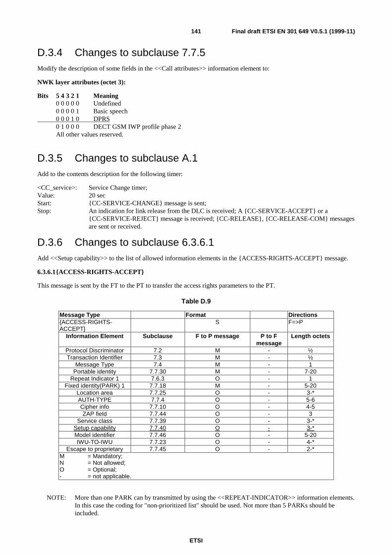
ETSI
Final draft ETSI EN 301 649 V0.5.1 (1999-11)141
D.3.4 Changes to subclause 7.7.5Modify the description of some fields in the <<Call attributes>> information element to:
NWK layer attributes (octet 3):
Bits 5 4 3 2 1 Meaning0 0 0 0 0 Undefined0 0 0 0 1 Basic speech0 0 0 1 0 DPRS0 1 0 0 0 DECT GSM IWP profile phase 2All other values reserved.
D.3.5 Changes to subclause A.1Add to the contents description for the following timer:
<CC_service>: Service Change timer;Value: 20 secStart: {CC-SERVICE-CHANGE} message is sent;Stop: An indication for link release from the DLC is received; A {CC-SERVICE-ACCEPT} or a
{CC-SERVICE-REJECT} message is received; {CC-RELEASE}, {CC-RELEASE-COM} messagesare sent or received.
D.3.6 Changes to subclause 6.3.6.1Add <<Setup capability>> to the list of allowed information elements in the {ACCESS-RIGHTS-ACCEPT} message.
6.3.6.1{ACCESS-RIGHTS-ACCEPT}
This message is sent by the FT to the PT to transfer the access rights parameters to the PT.
Table D.9
Message Type Format Directions{ACCESS-RIGHTS-ACCEPT}
S F=>P
Information Element Subclause F to P message P to Fmessage
Length octets
Protocol Discriminator 7.2 M - ½Transaction Identifier 7.3 M - ½
Message Type 7.4 M - 1Portable identity 7.7.30 M - 7-20
Repeat Indicator 1 7.6.3 O - 1Fixed identity(PARK) 1 7.7.18 M - 5-20
Location area 7.7.25 O - 3-*AUTH-TYPE 7.7.4 O - 5-6Cipher info 7.7.10 O - 4-5ZAP field 7.7.44 O - 3
Service class 7.7.39 O - 3-*Setup capability 7.7.40 O - 3-*Model identifier 7.7.46 O - 5-20IWU-TO-IWU 7.7.23 O - 4-*
Escape to proprietary 7.7.45 O - 2-*M = Mandatory;N = Not allowed;O = Optional;- = not applicable.
NOTE: More than one PARK can by transmitted by using the <<REPEAT-INDICATOR>> information elements.In this case the coding for "non-prioritized list" should be used. Not more than 5 PARKs should beincluded.

ETSI
Final draft ETSI EN 301 649 V0.5.1 (1999-11)142
D.3.7 Changes to subclause 6.3.6.17Add <<Setup capability>> to the list of allowed information elements in the {LOCATE-ACCEPT} message
6.3.6.17 {LOCATE-ACCEPT}
This message is sent by the FT to the PT to indicate that location updating or attach has been completed.
Table D.10
Message Type Format Directions{LOCATE-ACCEPT} S F=>P
Information Element Subclause F to P message P to Fmessage
Length octets
Protocol Discriminator 7.2 M - ½Transaction Identifier 7.3 M - ½
Message Type 7.4 M - 1Portable identity 1 7.7.30 M - 2-20
Location area 7.7.25 M - 3-*Use TPUI 7.6.2 O - 1
NWK assigned identity 7.7.28 O - 5-20Ext h/o indicator 7.7.51 O - 3Setup capability 7.7.40 O - 3-*
Duration 7.7.13 O - 4IWU-TO-IWU 7.7.23 O - 4-*
Model identifier 7.7.46 O - 5-20Escape to proprietary 7.7.45 O - 2-*
M = Mandatory.O = Optional.
NOTE: This element may contain zero length contents if a new TPUI is not assigned.
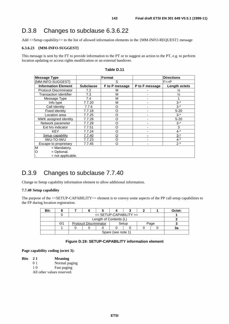
ETSI
Final draft ETSI EN 301 649 V0.5.1 (1999-11)143
D.3.8 Changes to subclause 6.3.6.22Add <<Setup capability>> to the list of allowed information elements in the {MM-INFO-REQUEST} message
6.3.6.23 {MM-INFO-SUGGEST}
This message is sent by the FT to provide information to the PT or to suggest an action to the PT, e.g. to performlocation updating or access rights modification or an external handover.
Table D.11
Message Type Format Directions{MM-INFO-SUGGEST} S F=>P
Information Element Subclause F to P message P to F message Length octetsProtocol Discriminator 7.2 M - ½Transaction Identifier 7.3 M - ½
Message Type 7.4 M - 1Info type 7.7.20 M - 3-*
Call Identity 7.7.6 O - 3-*Fixed identity 7.7.18 O - 5-20Location area 7.7.25 O - 3-*
NWK assigned identity 7.7.28 O - 5-20Network parameter 7.7.29 O - 3-*
Ext h/o indicator 7.7.51 O - 3KEY 7.7.24 O - 4-*
Setup capability 7.7.40 O - 3-*IWU-TO-IWU 7.7.23 O - 4-*
Escape to proprietary 7.7.45 O - 2-*M = Mandatory.O = Optional.- = not applicable.
D.3.9 Changes to subclause 7.7.40Change to Setup capability information element to allow additional information.
7.7.40 Setup capability
The purpose of the <<SETUP-CAPABILITY>> element is to convey some aspects of the PP call setup capabilities tothe FP during location registration.
Bit: 8 7 6 5 4 3 2 1 Octet:0 << SETUP-CAPABILITY >> 1
Length of Contents (L) 20/1 Protocol Discriminator Setup Page 31 0 0 0 0 0 0 0 3a
Spare (see note 1)
Figure D.19: SETUP-CAPABILITY information element
Page capability coding (octet 3):
Bits 2 1 Meaning0 1 Normal paging1 0 Fast pagingAll other values reserved.
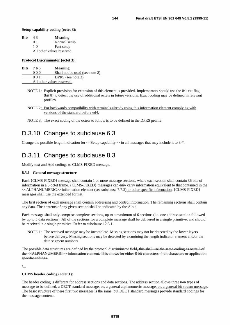
ETSI
Final draft ETSI EN 301 649 V0.5.1 (1999-11)144
Setup capability coding (octet 3):
Bits 4 3 Meaning0 1 Normal setup1 0 Fast setupAll other values reserved.
Protocol Discriminator (octet 3):
Bits 7 6 5 Meaning0 0 0 Shall not be used (see note 2)0 0 1 DPRS (see note 3)All other values reserved.
NOTE 1: Explicit provision for extension of this element is provided. Implementors should use the 0/1 ext flag(bit 8) to detect the use of additional octets in future versions. Exact coding may be defined in relevantprofiles.
NOTE 2: For backwards compatibility with terminals already using this information element complying withversions of the standard before ed4.
NOTE 3: The exact coding of the octets to follow is to be defined in the DPRS profile.
D.3.10 Changes to subclause 6.3Change the possible length indication for <<Setup capability>> in all messages that may include it to 3-*.
D.3.11 Changes to subclause 8.3Modify text and Add codings to CLMS-FIXED message.
8.3.1 General message structure
Each {CLMS-FIXED} message shall contain 1 or more message sections, where each section shall contain 36 bits ofinformation in a 5 octet frame. {CLMS-FIXED} messages can only carry information equivalent to that contained in the<<ALPHANUMERIC>> information element (see subclause 7.7.3) or other specific information. {CLMS-FIXED}messages shall use the extended format.
The first section of each message shall contain addressing and control information. The remaining sections shall containany data. The contents of any given section shall be indicated by the A bit.
Each message shall only comprise complete sections, up to a maximum of 6 sections (i.e. one address section followedby up to 5 data sections). All of the sections for a complete message shall be delivered in a single primitive, and shouldbe received in a single primitive. Refer to subclause 12.3.1.
NOTE 1: The received message may be incomplete. Missing sections may not be detected by the lower layersbefore delivery. Missing sections may be detected by examining the length indicator element and/or thedata segment numbers.
The possible data structures are defined by the protocol discriminator field, this shall use the same coding as octet 3 ofthe <<ALPHANUMERIC>> information element. This allows for either 8 bit characters, 4 bit characters or applicationspecific codings.
/...
CLMS header coding (octet 1):
The header coding is different for address sections and data sections. The address section allows three two types ofmessage to be defined, a DECT standard message, or, a general alphanumeric message, or, a general bit stream message.The basic structure of these first two messages is the same, but DECT standard messages provide standard codings forthe message contents.
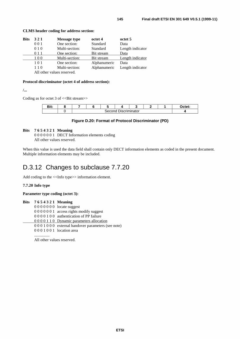
ETSI
Final draft ETSI EN 301 649 V0.5.1 (1999-11)145
CLMS header coding for address section:
Bits 3 2 1 Message type octet 4 octet 50 0 1 One section: Standard Data0 1 0 Multi-section: Standard Length indicator0 1 1 One section: Bit stream Data1 0 0 Multi-section: Bit stream Length indicator1 0 1 One section: Alphanumeric Data1 1 0 Multi-section: Alphanumeric Length indicatorAll other values reserved.
Protocol discriminator (octet 4 of address section):
/...
Coding as for octet 3 of <<Bit stream>>
Bit: 8 7 6 5 4 3 2 1 Octet:0 Second Discriminator 4
Figure D.20: Format of Protocol Discriminator (PD)
Bits 7 6 5 4 3 2 1 Meaning0 0 0 0 0 0 1 DECT Information elements codingAll other values reserved.
When this value is used the data field shall contain only DECT information elements as coded in the present document.Multiple information elements may be included.
D.3.12 Changes to subclause 7.7.20Add coding to the <<Info type>> information element.
7.7.20 Info type
Parameter type coding (octet 3):
Bits 7 6 5 4 3 2 1 Meaning0 0 0 0 0 0 0 locate suggest0 0 0 0 0 0 1 access rights modify suggest0 0 0 0 1 0 0 authentication of PP failure0 0 0 0 1 1 0 Dynamic parameters allocation0 0 0 1 0 0 0 external handover parameters (see note)0 0 0 1 0 0 1 location area...............All other values reserved.
ETSI
Final draft ETSI EN 301 649 V0.5.1 (1999-11)146
D.3.13 Changes to subclause 8.2.1Modify LCE header coding allocation
8.2.1 Short format message
/...
LCE header coding
The LCE header coding shall indicate the U-plane service (MAC service type) required. In addition it may indicatewhether the message is used to start ringing at the portable part, see subclause 14.4:
Bits 3 2 1 U-plane service (MAC service type)0 0 0 None0 0 1 Unknown (MAC service type) & Ringing0 1 0 Escape Reserved0 1 1 Unknown
......
D.3.14 Changes to subclause 8.2.2Add to the clause.
8.2.2 Long format message
/...
When LCE Header = 010 (escape) different coding is provided as follows:
Bit: 8 7 6 5 4 3 2 1 Octet:X X X X W=1 LCE Header = 010
(escape)1
AttributesDiscriminator
TPUI Address 2
TPUI Address (cont) 3TPUI Address (cont) 4
Target bearersspare (0000)
MAC pkt lifeConnection Identity
5
• Discriminator
Bits 8 7 6 5 Meaning0 0 0 0 User specific0 0 0 1 Resume pagingAll other values reserved.
• Connection identity
Bits 4 3 2 1 Meaning0 0 0 0 Not applicable1 n n n LCE=n n n
ETSI
Final draft ETSI EN 301 649 V0.5.1 (1999-11)147
D.3.15 Add subclause 14.514.5 Resume Paging
This procedure is closely related to MAC resume procedure as defined in EN 300 175-3 [3].
If MAC layer paging fails (e.g. PP has moved to another cluster) the FT LLME shall request the FT-NWK LCE forinitiating a LCE resumption providing the ECN of the related link.
As result the LCE shall construct a Long Page message as defined in, subclause 8.2.2 using the LCE header code"escape" and the discriminator code "Resume paging". The Connection identity for the connection to be resumed shallbe provided.
The LCE shall issue the {LCE-REQUEST-PAGE} message using either a DL_BROADCAST-req primitive or aDL_EXPEDITED-req primitive via the B-SAP. It shall then mark the link as in the "RESUMPTION PENDING" state,and shall start timer <LCE.03>.
If timer <LCE.03> expires before the wanted link is established, the LCE should resubmit the {LCE-REQUEST-PAGE}message. Resubmitted messages shall only be issued at a lower priority than other outstanding B-FORMAT messages. Amessage may be resubmitted a maximum of N300 times, before it is discarded. (N300 is an application specific value.Recommended value for voice applications is 3).
If the {LCE-REQUEST-PAGE} message is successfully received by the intended PT, it shall check whether there is alink in ACTIVE state which can be identified by the received in the paging message Connection identity. If such linkexists the PT shall construct a LCE-PAGE-RESPONSE message following the rules as described in subclause 14.2.3and shall send it in a DL-DATA-req primitive over the existing link.
NOTE: The arrival of this message at PT MAC layer will consequently trigger a PT initiated connectionresumption at MAC.
On receipt of the LCE-PAGE-RESPONSE (over the resumed connection) the FT-LCE shall check the identity containedin this response against a list of outstanding {LCE-REQUEST-PAGE} messages, and if the identity matches the identityassociated with this link FT-LCE shall mark the link as "LINK ESTABLISHED"; it shall stop timer <LCE.03> and shallcontinue with normal operation (i.e. with the action that was the reason for the required resumption).
D.3.16 Add Distributed Communication changes to Base standardAnnex E introduces the concept of the Distributed communications in DECT. Number of changes to the DECT CI,EN 300 175, standard are required.
D.3.17 U-plane frame typeEN 300 175-5 [5], 7.7.5.
Bits 4 3 2 1 Meaning....1 0 1 0 FU10a/c1 0 1 1 FU10bAll other values reserved.
ETSI
Final draft ETSI EN 301 649 V0.5.1 (1999-11)148
Annex E (normative):Distributed Communication Specification ProtocolRequirements
E.1 Definitions and Abbreviations
E.1.1 DefinitionsActive terminal/member: A member of a DCDL-net that is powered-up, has locked to the MASTER and has announceditself as being present to the MASTER.
DECT Distributed communications: DECT Distributed communication is regarded as a communication capability of aDECT Local Network that allows a number of DECT terminals to co-exists and directly communicate with each other,such networks shall be referred hereafter as Distributed Communications DECT Local Network (DCDL-net).
DECT Local Network (DL-net): A DL-net is a local network comprising number of DECT terminals capable ofinter-communicating which may but need not be connected to an external network.
Hybrid Part (HyP): A HyP is a DECT terminal that provides FT as well as PT capabilities:
• it can receive on any slot from 0 to 23;
• it can transmit on any slot from 0 to 23);
• it may transmit at least both a connectionless or a dummy bearer following the EN 300 175-3 [3] specification[1];
• it can listen to any of a connectionless or a dummy bearer transmitted by another HyP;
• it is capable of synchronizing to any of a connectionless or dummy bearer transmitted by another HyP: includingsynchronization to the transmitter PSCN, frame and multiframe numbers, etc.
whether it is playing the role of a FT or a PT depends on the role the terminal has in the link establishment procedure asdefined in the present document.
MASTER: A specially dedicated terminal determining the DCDL-net synchronization and providing means of intraDCDL-net control and exchange of information. By definition a MASTER is always an Active terminal.
E.1.2 AbbreviationsCSDb Common System Database
DCDL-net Distributed Communication DECT Local Network
DL-net DECT Local Network
HyP Hybrid Part
IdN Identity Number
ETSI
Final draft ETSI EN 301 649 V0.5.1 (1999-11)149
E.2 General Requirements
E.2.1 DCDL-netA DL-net that supports Distributed communications (DCDL-net) shall:
• Have allocated a MASTER terminal to determine the intra-network synchronization and provide common for theDCDL-net information and control. If there is a terminal that is intended for constant operation (e.g. the terminalthat provides voice services to an external network and is not intended to be frequently powered-down) thisshould be allocated as MASTER.
• Maintain for the whole time of it existence a DCDL-net System Control Bearer transmitted by the MASTER; ifthe MASTER is to switch-off or leave it should assign another active member as the new MASTER; the SystemControl Bearer should be a connectionless bearer and shall continuously provide information about the currentlyactive members; all active DCDL-net members shall synchronize to the System Control Bearer, i.e. to theMASTER and shall continuously listen to it and retrieve the necessary information to maintain its communicationwithin the DCDL-net.
• Posses (meaning every member of the DCDL-net shall independently posses) a Common Subscription Database(CSDb) including: common to all members AC, DCK, PLI and LAL (provision of every single value depends onthe support of a particular feature); List with all members distinguished by their identification number (IdN);Information for all member including RFPI, PARK, IPUI and TPUI, terminal capabilities, etc.
• Provide means of control of the usage of the resource throughout the DCDL-net by advising reduction of thenumber of used bearers (valid for multi-bearer connections).
E.2.2 SubscriptionFor establishment of the necessary values in the CSDb the following rules shall apply:
• a basic ARI should be assign to particular DCDL-net at the DCDL-net initialization; this should be the ARI of theterminal assign to be the DCDL-net MASTER at this time;
• to become a member of a DCDL-net a terminal shall subscribe to the MASTER;
• the Obtain access rights procedure shall be used to provide the PARK, PLI and IPUI; RFPI, as well as, the IdNand the TPUIs may be derived from this information;
• the Location registration procedure shall be used to provide LAL, it may be used to assign the TPUI but it can beas well automatically extracted from the IPUI instead; if TPUI is assigned during Location Registration this shalloverwrite any derived TPUI;
• if provision of Encryption is supported after, subscription is accomplished, both terminals shall establish a DCK,shall cipher the link and all common for the DCDL-net keys shall be after that provided by the master to theapplicant over this ciphered link - Parameter Retrieval procedure shall be used; Parameter retrieval proceduremay be used for assignment of a RFPI as well in this case the assigned value shall overwrite any derived value;
• parameter retrieval procedure shall be used for provision to the applicant of information for all DCDL-netmembers. If encryption is provided this procedure shall be performed over an encrypted link;
• the DCDL-net's CSDb may be re-established on user request; the MASTER shall perform modification of userparameters procedure to all members; this action should be performed with care as not all members may be activeat this moment and the change may make them implicitly excluded from the DCDL-net.
ETSI
Final draft ETSI EN 301 649 V0.5.1 (1999-11)150
E.2.3 CommunicationA Terminal that wants to participate in a DL-net that supports distributed communication shall behaves as follow:
• only members of a DCDL-net can communicate within the DCDL-net;
• to become a member, a terminal (behaving as a PT ) shall request access rights from the MASTER of theDCDL-net; during the assignment of the membership access rights the applicant shall be allocated all necessarysubscription data; its own data shall become part of the CSDb; shall obtain information for all members of theDCDL-net (independent of whether they are currently active or not);
• if a terminal is a member of a DCDL-net when it is powered-up, or switched to search for a DCDL-net MASTERit shall synchronize to the current MASTER (frame and multiframe numbers, PSCN, etc.) and shall constantlyfrom this point of time on update its information as which member is currently active and may be accessed;
• shall announce itself to the MASTER as being active and thereby accessible;
• shall start listening for Paging, and, may start listening to all slots for a direct link establishment;
• if a terminal recognizes a specific Paging message that contains its TPUI and the Id of another terminal, it shallinitiate direct link establishment to that terminal behaving as a PT in an Indirect FT initiated link establishmentprocedure as specified in EN 300 175-5 [5], subclause 14.2.2;
• if the User of a terminal wants to initiate a call and the desired terminal is currently active the User's terminalshall attempt a direct link establishment if this fails it shall request the MASTER to transmit a Paging to thedesired terminal; if the desired terminal is not currently active the user shall not initiate this procedure.
It should be preferable that every active HyP terminal constantly listen to all frames thereby direct link establishmenttowards this terminal shall always succeed. However to allow some terminal to be part of the DCDL-net which due topower consumption would favour low duty cycle mode a special paging procedure need to be applied when suchterminals need to be accessed being in low duty cycle mode.
NOTE: See clause E.5 for graphic representation of some of the communications scenarios.
E.3 Procedure description
E.3.1 HyP IdentitiesA HyP shall be assigned by the manufacturer a RFPI and an IPEI which should represent the two sides of the HyP.
The IPUI-N (equal to IPEI) shall be used by the HyP to request membership access rights from the DCDL-netMASTER; the RFPI may be used by the HyP for the DCDL-net ARI if a new DCDL-net is to be established and thisHyP is been allocated by the user to be the MASTER, see subclause E.3.10.2.
E.3.2 Membership Access Rights AllocationFor the Membership Access Rights Allocation procedure the normal DECT Obtain access Rights procedure shall beused.
The applicant shall provide its capabilities description indicated in a <<Terminal capability>>, a <<Set-up capability>>and an <<IWU-TO-IWU>> information elements included into the {ACCESS-RIGHTS-REQUEST} message.
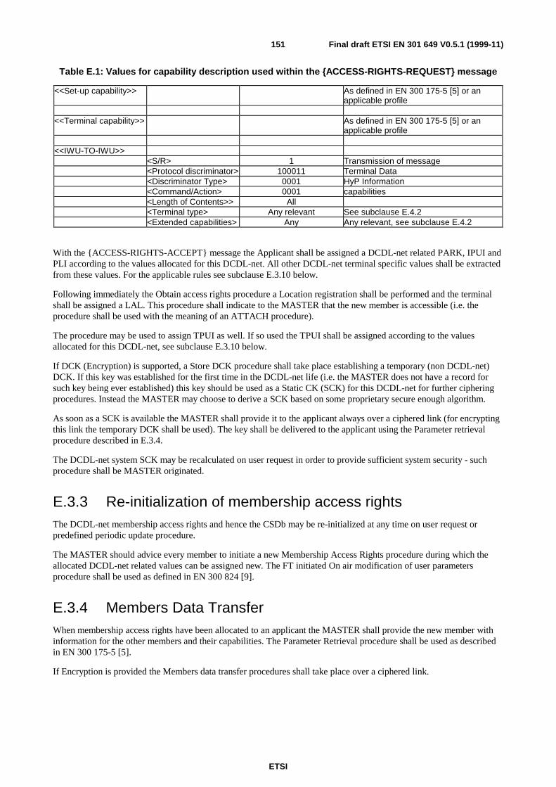
ETSI
Final draft ETSI EN 301 649 V0.5.1 (1999-11)151
Table E.1: Values for capability description used within the {ACCESS-RIGHTS-REQUEST} message
<<Set-up capability>> As defined in EN 300 175-5 [5] or anapplicable profile
<<Terminal capability>> As defined in EN 300 175-5 [5] or anapplicable profile
<<IWU-TO-IWU>><S/R> 1 Transmission of message<Protocol discriminator> 100011 Terminal Data<Discriminator Type> 0001 HyP Information<Command/Action> 0001 capabilities<Length of Contents>> All<Terminal type> Any relevant See subclause E.4.2<Extended capabilities> Any Any relevant, see subclause E.4.2
With the {ACCESS-RIGHTS-ACCEPT} message the Applicant shall be assigned a DCDL-net related PARK, IPUI andPLI according to the values allocated for this DCDL-net. All other DCDL-net terminal specific values shall be extractedfrom these values. For the applicable rules see subclause E.3.10 below.
Following immediately the Obtain access rights procedure a Location registration shall be performed and the terminalshall be assigned a LAL. This procedure shall indicate to the MASTER that the new member is accessible (i.e. theprocedure shall be used with the meaning of an ATTACH procedure).
The procedure may be used to assign TPUI as well. If so used the TPUI shall be assigned according to the valuesallocated for this DCDL-net, see subclause E.3.10 below.
If DCK (Encryption) is supported, a Store DCK procedure shall take place establishing a temporary (non DCDL-net)DCK. If this key was established for the first time in the DCDL-net life (i.e. the MASTER does not have a record forsuch key being ever established) this key should be used as a Static CK (SCK) for this DCDL-net for further cipheringprocedures. Instead the MASTER may choose to derive a SCK based on some proprietary secure enough algorithm.
As soon as a SCK is available the MASTER shall provide it to the applicant always over a ciphered link (for encryptingthis link the temporary DCK shall be used). The key shall be delivered to the applicant using the Parameter retrievalprocedure described in E.3.4.
The DCDL-net system SCK may be recalculated on user request in order to provide sufficient system security - suchprocedure shall be MASTER originated.
E.3.3 Re-initialization of membership access rightsThe DCDL-net membership access rights and hence the CSDb may be re-initialized at any time on user request orpredefined periodic update procedure.
The MASTER should advice every member to initiate a new Membership Access Rights procedure during which theallocated DCDL-net related values can be assigned new. The FT initiated On air modification of user parametersprocedure shall be used as defined in EN 300 824 [9].
E.3.4 Members Data TransferWhen membership access rights have been allocated to an applicant the MASTER shall provide the new member withinformation for the other members and their capabilities. The Parameter Retrieval procedure shall be used as describedin EN 300 175-5 [5].
If Encryption is provided the Members data transfer procedures shall take place over a ciphered link.

ETSI
Final draft ETSI EN 301 649 V0.5.1 (1999-11)152
The information related to every member shall include:
• the IdN of the member - all DCDL-net subscription related data for particular member may be derived from itsIdN, see subclause E.3.10 below;
• the Member Capability as provided in the {ACCESS-RIGHTS-REQUEST} message during the membershipsubscription including the <<Terminal capability>>, the <<Set-up>> capability and specific devise informationas provided in the <<iwu-to-iwu>>.
Table E.2: Values used within the {MM-INFO-SUGGEST} message
Information element Field within theinformation element
Standard values withinthe field/IE
Normative action/comment
<<Info-type>><Length of Contents > 1<ext> 1<Parameter type> 0100101 Distributed communication download
<<Repeat indicator>> Optional to use from the MASTER toprovide information for number ofmembers in one message. Mandatory tounderstand from the applicant/member.
<<IWU-TO-IWU>><S/R> 1 Transmission of message<Protocol discriminator> 100011 Terminal Data<Discriminator Type> 0001 HyP Information<Command/Action> 0001 capabilities as provided by the
<<iwu-to-iwu>><Length of Contents>> All Determines whether the <Terminal data>
field is included or not<Terminal type> Any Any relevant, see subclause E.4.2<Extended capabilities> Any Any relevant, see subclause E.4.2<Terminal Id> All IdN-Mean to distinguish different
terminals<Terminal data>
<<Terminal Capability >> The complete information element asreceived during subscription
<<Set-up capability>> The complete information element asreceived during subscription
This procedure may be used to provide as well RFPI or/and TPUIs by including the corresponding information elements<<Fixed Id>> or/and <<Portable Id>> as defined in EN 300 175-5 [5], into the <Terminal data> field. The valuesassigned shall be in accordance with the rules provided in subclause E.3.10 and if assigned shall overwrite any derivedvalue.
As a fall back the Members Data Transfer procedure may be used by all members to refresh their information on theavailable members by requesting update from the MASTER. For these purposes the PT initiated parameter retrievalprocedure shall be used.
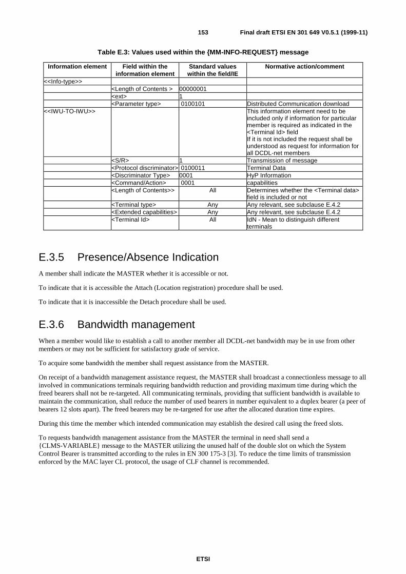
ETSI
Final draft ETSI EN 301 649 V0.5.1 (1999-11)153
Table E.3: Values used within the {MM-INFO-REQUEST} message
Information element Field within theinformation element
Standard valueswithin the field/IE
Normative action/comment
<<Info-type>><Length of Contents > 00000001<ext> 1<Parameter type> 0100101 Distributed Communication download
<<IWU-TO-IWU>> This information element need to beincluded only if information for particularmember is required as indicated in the<Terminal Id> fieldIf it is not included the request shall beunderstood as request for information forall DCDL-net members
<S/R> 1 Transmission of message<Protocol discriminator> 0100011 Terminal Data<Discriminator Type> 0001 HyP Information<Command/Action> 0001 capabilities<Length of Contents>> All Determines whether the <Terminal data>
field is included or not<Terminal type> Any Any relevant, see subclause E.4.2<Extended capabilities> Any Any relevant, see subclause E.4.2<Terminal Id> All IdN - Mean to distinguish different
terminals
E.3.5 Presence/Absence IndicationA member shall indicate the MASTER whether it is accessible or not.
To indicate that it is accessible the Attach (Location registration) procedure shall be used.
To indicate that it is inaccessible the Detach procedure shall be used.
E.3.6 Bandwidth managementWhen a member would like to establish a call to another member all DCDL-net bandwidth may be in use from othermembers or may not be sufficient for satisfactory grade of service.
To acquire some bandwidth the member shall request assistance from the MASTER.
On receipt of a bandwidth management assistance request, the MASTER shall broadcast a connectionless message to allinvolved in communications terminals requiring bandwidth reduction and providing maximum time during which thefreed bearers shall not be re-targeted. All communicating terminals, providing that sufficient bandwidth is available tomaintain the communication, shall reduce the number of used bearers in number equivalent to a duplex bearer (a peer ofbearers 12 slots apart). The freed bearers may be re-targeted for use after the allocated duration time expires.
During this time the member which intended communication may establish the desired call using the freed slots.
To requests bandwidth management assistance from the MASTER the terminal in need shall send a{CLMS-VARIABLE} message to the MASTER utilizing the unused half of the double slot on which the SystemControl Bearer is transmitted according to the rules in EN 300 175-3 [3]. To reduce the time limits of transmissionenforced by the MAC layer CL protocol, the usage of CLF channel is recommended.
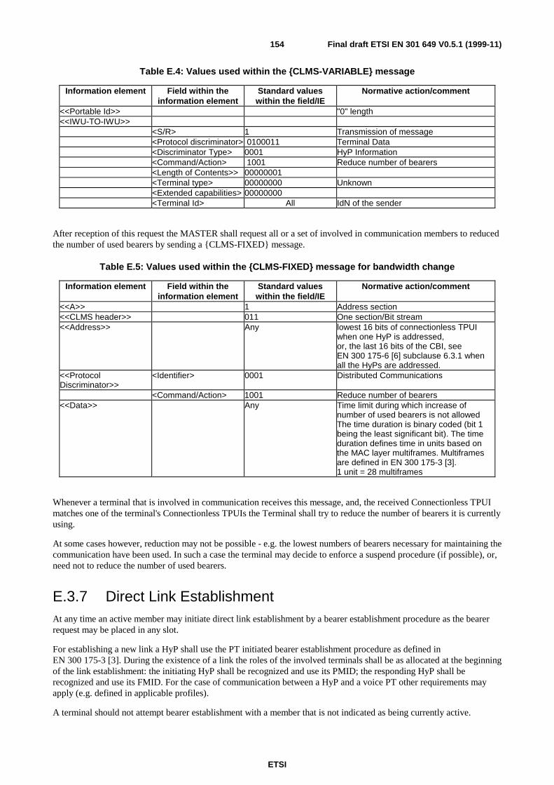
ETSI
Final draft ETSI EN 301 649 V0.5.1 (1999-11)154
Table E.4: Values used within the {CLMS-VARIABLE} message
Information element Field within theinformation element
Standard valueswithin the field/IE
Normative action/comment
<<Portable Id>> "0" length<<IWU-TO-IWU>>
<S/R> 1 Transmission of message<Protocol discriminator> 0100011 Terminal Data<Discriminator Type> 0001 HyP Information<Command/Action> 1001 Reduce number of bearers<Length of Contents>> 00000001<Terminal type> 00000000 Unknown<Extended capabilities> 00000000<Terminal Id> All IdN of the sender
After reception of this request the MASTER shall request all or a set of involved in communication members to reducedthe number of used bearers by sending a {CLMS-FIXED} message.
Table E.5: Values used within the {CLMS-FIXED} message for bandwidth change
Information element Field within theinformation element
Standard valueswithin the field/IE
Normative action/comment
<<A>> 1 Address section<<CLMS header>> 011 One section/Bit stream<<Address>> Any lowest 16 bits of connectionless TPUI
when one HyP is addressed,or, the last 16 bits of the CBI, seeEN 300 175-6 [6] subclause 6.3.1 whenall the HyPs are addressed.
<<ProtocolDiscriminator>>
<Identifier> 0001 Distributed Communications
<Command/Action> 1001 Reduce number of bearers<<Data>> Any Time limit during which increase of
number of used bearers is not allowedThe time duration is binary coded (bit 1being the least significant bit). The timeduration defines time in units based onthe MAC layer multiframes. Multiframesare defined in EN 300 175-3 [3].1 unit = 28 multiframes
Whenever a terminal that is involved in communication receives this message, and, the received Connectionless TPUImatches one of the terminal's Connectionless TPUIs the Terminal shall try to reduce the number of bearers it is currentlyusing.
At some cases however, reduction may not be possible - e.g. the lowest numbers of bearers necessary for maintaining thecommunication have been used. In such a case the terminal may decide to enforce a suspend procedure (if possible), or,need not to reduce the number of used bearers.
E.3.7 Direct Link EstablishmentAt any time an active member may initiate direct link establishment by a bearer establishment procedure as the bearerrequest may be placed in any slot.
For establishing a new link a HyP shall use the PT initiated bearer establishment procedure as defined inEN 300 175-3 [3]. During the existence of a link the roles of the involved terminals shall be as allocated at the beginningof the link establishment: the initiating HyP shall be recognized and use its PMID; the responding HyP shall berecognized and use its FMID. For the case of communication between a HyP and a voice PT other requirements mayapply (e.g. defined in applicable profiles).
A terminal should not attempt bearer establishment with a member that is not indicated as being currently active.
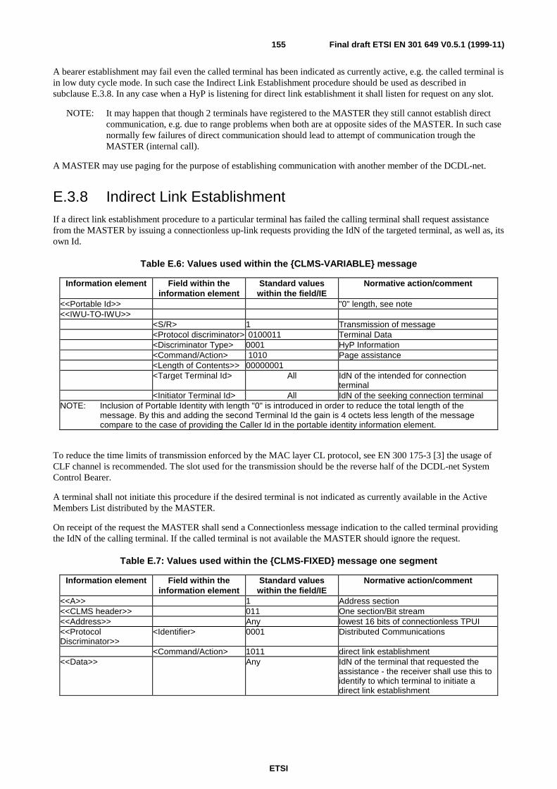
ETSI
Final draft ETSI EN 301 649 V0.5.1 (1999-11)155
A bearer establishment may fail even the called terminal has been indicated as currently active, e.g. the called terminal isin low duty cycle mode. In such case the Indirect Link Establishment procedure should be used as described insubclause E.3.8. In any case when a HyP is listening for direct link establishment it shall listen for request on any slot.
NOTE: It may happen that though 2 terminals have registered to the MASTER they still cannot establish directcommunication, e.g. due to range problems when both are at opposite sides of the MASTER. In such casenormally few failures of direct communication should lead to attempt of communication trough theMASTER (internal call).
A MASTER may use paging for the purpose of establishing communication with another member of the DCDL-net.
E.3.8 Indirect Link EstablishmentIf a direct link establishment procedure to a particular terminal has failed the calling terminal shall request assistancefrom the MASTER by issuing a connectionless up-link requests providing the IdN of the targeted terminal, as well as, itsown Id.
Table E.6: Values used within the {CLMS-VARIABLE} message
Information element Field within theinformation element
Standard valueswithin the field/IE
Normative action/comment
<<Portable Id>> "0" length, see note<<IWU-TO-IWU>>
<S/R> 1 Transmission of message<Protocol discriminator> 0100011 Terminal Data<Discriminator Type> 0001 HyP Information<Command/Action> 1010 Page assistance<Length of Contents>> 00000001<Target Terminal Id> All IdN of the intended for connection
terminal<Initiator Terminal Id> All IdN of the seeking connection terminal
NOTE: Inclusion of Portable Identity with length "0" is introduced in order to reduce the total length of themessage. By this and adding the second Terminal Id the gain is 4 octets less length of the messagecompare to the case of providing the Caller Id in the portable identity information element.
To reduce the time limits of transmission enforced by the MAC layer CL protocol, see EN 300 175-3 [3] the usage ofCLF channel is recommended. The slot used for the transmission should be the reverse half of the DCDL-net SystemControl Bearer.
A terminal shall not initiate this procedure if the desired terminal is not indicated as currently available in the ActiveMembers List distributed by the MASTER.
On receipt of the request the MASTER shall send a Connectionless message indication to the called terminal providingthe IdN of the calling terminal. If the called terminal is not available the MASTER should ignore the request.
Table E.7: Values used within the {CLMS-FIXED} message one segment
Information element Field within theinformation element
Standard valueswithin the field/IE
Normative action/comment
<<A>> 1 Address section<<CLMS header>> 011 One section/Bit stream<<Address>> Any lowest 16 bits of connectionless TPUI<<ProtocolDiscriminator>>
<Identifier> 0001 Distributed Communications
<Command/Action> 1011 direct link establishment<<Data>> Any IdN of the terminal that requested the
assistance - the receiver shall use this toidentify to which terminal to initiate adirect link establishment

ETSI
Final draft ETSI EN 301 649 V0.5.1 (1999-11)156
The called terminal should initiate direct link establishment to the calling terminal. As it may not be for whatever reasoncapable of doing this, the initiating terminal should not wait for ever. It may repeat the procedure max 3 times and incase of all 3 attempts have failed the user should be informed for the call attempt failure.
E.3.9 MASTER management
E.3.9.1 MASTER assign
For setting up a DCDL-net a MASTER terminal is needed which shall transmit a System Control Bearer. The User shallensure that a MASTER is available which MASTER shall start transmission of such a bearer on User request for setting-up a DCDL-net. The invocation of MASTER assign procedure is not specified and is left to the implementers assumingthat User intervention shall be always required.
If a DCDL-net has been already set-up, however, during a reasonable time a member of a DCDL-net terminal cannotfind the DCDL-net System Control Bearer proper indication shall be provided to the User of the terminal.
The DCDL-net System Control bearer shall be a connectionless bearer due to the fact that the DCDL-net systeminformation it transmitted in connectionless messages.
If a member of DCDL-net has been assigned as MASTER this shall be responsible for the transmission of theConnectionless DCDL-net system bearer. This bearer shall be present if at least one member of a DCDL-net is active.
Establishment and maintenance of this bearer shall be done in accordance to the requirements of the EN 300 175-3 [3].
E.3.9.2 MASTER Change
If a MASTER is to leave the DCDL-net it shall allocate any of the currently active members as its successor. Aconnectionless message shall be sent.
Table E.8: Values used within the {CLMS-FIXED} message one segment
Information element Field within theinformation element
Standard valueswithin the field/IE
Normative action/comment
<<A>> 1 Address section<<CLMS header>> 011 One section/Bit stream<<Address>> Any lowest 16 bits of connectionless TPUI<<ProtocolDiscriminator>>
<Identifier> 0001 Distributed Communications
<Command/Action> 1100 master change<<Data>> Any do not care bits
The current MASTER shall start a timer and shall monitor the air for a new System Control Bearer establishment - avalue of 4 sec is recommended. When such is found the current MASTER shall inform all active members for thechange of the bearer position and shall close its activities -"connectionless or dummy bearer position" shall be used.
If during this time no new System bearer is found the MASTER shall request another active member to undertake itsresponsibilities.
E.3.9.3 DCDL-net System bearer management
The System bearer shall be a connectionless bearer as defined in EN 300 175-3 [3].
In addition to the information normally transmitted when no additional dummy bearer is available, the MASTER shalltransmit specific DCDL-net members related information in regular intervals - it is recommended that the first segmentof this message occurs every 4 seconds.
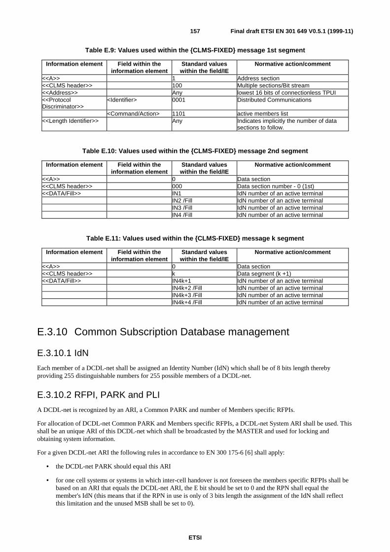
ETSI
Final draft ETSI EN 301 649 V0.5.1 (1999-11)157
Table E.9: Values used within the {CLMS-FIXED} message 1st segment
Information element Field within theinformation element
Standard valueswithin the field/IE
Normative action/comment
<<A>> 1 Address section<<CLMS header>> 100 Multiple sections/Bit stream<<Address>> Any lowest 16 bits of connectionless TPUI<<ProtocolDiscriminator>>
<Identifier> 0001 Distributed Communications
<Command/Action> 1101 active members list<<Length Identifier>> Any Indicates implicitly the number of data
sections to follow.
Table E.10: Values used within the {CLMS-FIXED} message 2nd segment
Information element Field within theinformation element
Standard valueswithin the field/IE
Normative action/comment
<<A>> 0 Data section<<CLMS header>> 000 Data section number - 0 (1st)<<DATA/Fill>> IN1 IdN number of an active terminal
IN2 /Fill IdN number of an active terminalIN3 /Fill IdN number of an active terminalIN4 /Fill IdN number of an active terminal
Table E.11: Values used within the {CLMS-FIXED} message k segment
Information element Field within theinformation element
Standard valueswithin the field/IE
Normative action/comment
<<A>> 0 Data section<<CLMS header>> k Data segment (k +1)<<DATA/Fill>> IN4k+1 IdN number of an active terminal
IN4k+2 /Fill IdN number of an active terminalIN4k+3 /Fill IdN number of an active terminalIN4k+4 /Fill IdN number of an active terminal
E.3.10 Common Subscription Database management
E.3.10.1 IdN
Each member of a DCDL-net shall be assigned an Identity Number (IdN) which shall be of 8 bits length therebyproviding 255 distinguishable numbers for 255 possible members of a DCDL-net.
E.3.10.2 RFPI, PARK and PLI
A DCDL-net is recognized by an ARI, a Common PARK and number of Members specific RFPIs.
For allocation of DCDL-net Common PARK and Members specific RFPIs, a DCDL-net System ARI shall be used. Thisshall be an unique ARI of this DCDL-net which shall be broadcasted by the MASTER and used for locking andobtaining system information.
For a given DCDL-net ARI the following rules in accordance to EN 300 175-6 [6] shall apply:
• the DCDL-net PARK should equal this ARI
• for one cell systems or systems in which inter-cell handover is not foreseen the members specific RFPIs shall bebased on an ARI that equals the DCDL-net ARI, the E bit should be set to 0 and the RPN shall equal themember's IdN (this means that if the RPN in use is only of 3 bits length the assignment of the IdN shall reflectthis limitation and the unused MSB shall be set to 0).

ETSI
Final draft ETSI EN 301 649 V0.5.1 (1999-11)158
• for multi-cell systems (determined by multi RFPs MASTER) with inter-cell handover care shall be taken duringallocation providing that the MASTERS RFPs are assigned with IdNs allowing inter-cell handover and being stillunique (e.g. not repeating a member IdN). See as well subclause E.3.11.
NOTE: For further extension of this specification assignment of a per Member specific DCDL-net Cell Locatormay be foreseen to allow Members to be multi-cell systems as well.
PLI should be assign to cover the PARI and to exclude the RPN.
E.3.10.3 IPUI
For the member specific IPUIs the IPUI type O as specified in EN 300 175-6 [6] subclause 6.2.3 should be used.
Different Numbers shall be assigned to every member of the DCDL-net, these numbers shall be used to identify everyparticular member and provide means to derive all subscription related data.
For the assignment of these numbers the following rule apply: the 8 least significant bits shall be the IdN number andthey shall be unique within the DCDL-net. The rest of the bits shall be set to "0".
E.3.10.4 TPUI and LAL
The LAL assigned during Location registration should be the same throughout the entire DCDL-net.
The individual assigned TPUI shall equal the IdN of the particular terminal with most significant bits following the rulesof EN 300 175-6 [6] for individual assigned TPUI.
To perform all connectionless operations the MASTER shall assign Connectionless TPUIs to each member that equalthe member's IdN with most significant bits following the rules of EN 300 175-6 [6] for.
E.3.10.5 Keys
A common AC shall be allocated to the DCDL-net by the user and shall be used during subscription and throughout theintra DCDL-net communication whenever authentication between two members is performed.
If encryption is supported a Static CK shall be allocated to the DCDL-net during the first subscription. Establishment ofthis key should be based on a Store DCK procedure performed using the AC, other proprietary establishment of this keymay be applied by the MASTER as well. The resulted key shall be the SCK used by the DCDL-net for furthercommunication.
E.3.11 Handover issuesFor one cell systems bearer handover shall be used to deal with transmission problems.
The MASTER may decide to change the position of the System Control Bearer. The new position shall be announced.As the new position may overlap with a slot on which there is ongoing communication between two members of theDCDL-net, as soon as these members receive the new System Control Bearer slot position they shall attempt handoverfor the bearer(s) which will overlap.
When the MASTER provides multi-cell environment, the Members should forbid inter-cell handover.
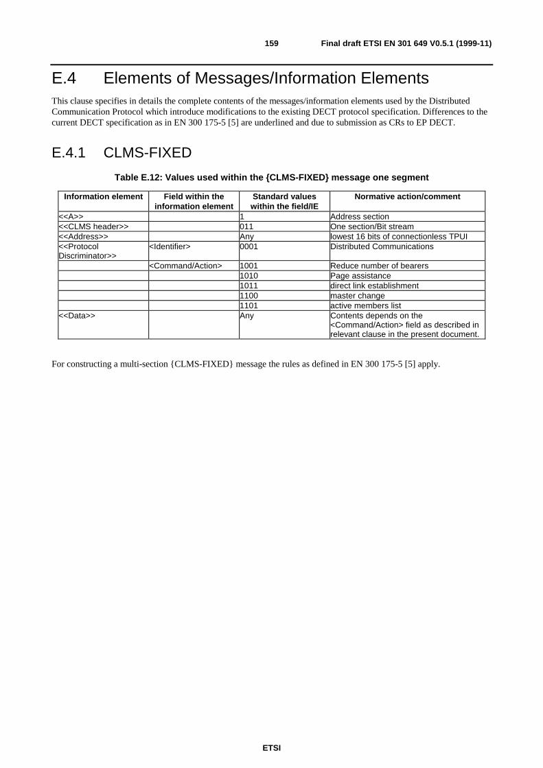
ETSI
Final draft ETSI EN 301 649 V0.5.1 (1999-11)159
E.4 Elements of Messages/Information ElementsThis clause specifies in details the complete contents of the messages/information elements used by the DistributedCommunication Protocol which introduce modifications to the existing DECT protocol specification. Differences to thecurrent DECT specification as in EN 300 175-5 [5] are underlined and due to submission as CRs to EP DECT.
E.4.1 CLMS-FIXED
Table E.12: Values used within the {CLMS-FIXED} message one segment
Information element Field within theinformation element
Standard valueswithin the field/IE
Normative action/comment
<<A>> 1 Address section<<CLMS header>> 011 One section/Bit stream<<Address>> Any lowest 16 bits of connectionless TPUI<<ProtocolDiscriminator>>
<Identifier> 0001 Distributed Communications
<Command/Action> 1001 Reduce number of bearers1010 Page assistance1011 direct link establishment1100 master change1101 active members list
<<Data>> Any Contents depends on the<Command/Action> field as described inrelevant clause in the present document.
For constructing a multi-section {CLMS-FIXED} message the rules as defined in EN 300 175-5 [5] apply.
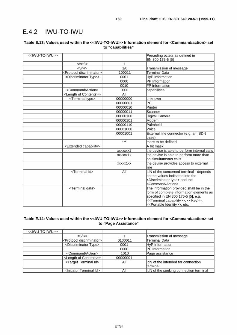
ETSI
Final draft ETSI EN 301 649 V0.5.1 (1999-11)160
E.4.2 IWU-TO-IWU
Table E.13: Values used within the <<IWU-TO-IWU>> Information element for <Command/action> setto "capabilities"
<<IWU-TO-IWU>> Preceding octets as defined inEN 300 175-5 [5]
<ext3> 1<S/R> 1/0 Transmission of message
<Protocol discriminator> 100011 Terminal Data<Discriminator Type> 0001 HyP Information
0000 PP Information0010 FP Information
<Command/Action> 0001 capabilities<Length of Contents>> All
<Terminal type> 00000000 unknown00000001 PC00000010 Printer00000011 Scanner00000100 Digital Camera00000101 Modem00000110 Palmheld00001000 Voice00001001 External line connector (e.g. an ISDN
base)*** more to be defined
<Extended capability> A bit maskxxxxxxx1 the devise is able to perform internal callsxxxxxx1x the devise is able to perform more than
on simultaneous callsxxxxx1xx the devise provides access to external
line<Terminal Id> All IdN of the concerned terminal - depends
on the values indicated into the<Discriminator type> and the<Command/Action>
<Terminal data> The information provided shall be in theform of complete information elements asspecified in EN 300 175-5 [5], e.g.<<Terminal capability>>, <<Key>>,<<Portable Identity>>, etc.
Table E.14: Values used within the <<IWU-TO-IWU>> Information element for <Command/action> setto "Page Assistance"
<<IWU-TO-IWU>><S/R> 1 Transmission of message
<Protocol discriminator> 0100011 Terminal Data<Discriminator Type> 0001 HyP Information
0000 PP Information<Command/Action> 1010 Page assistance
<Length of Contents>> 00000001<Target Terminal Id> All IdN of the intended for connection
terminal<Initiator Terminal Id> All IdN of the seeking connection terminal
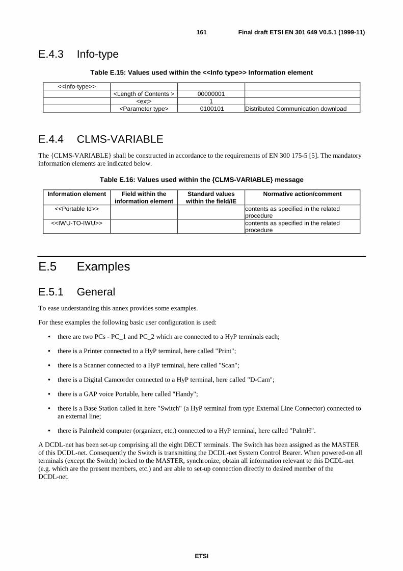
ETSI
Final draft ETSI EN 301 649 V0.5.1 (1999-11)161
E.4.3 Info-type
Table E.15: Values used within the <<Info type>> Information element
<<Info-type>><Length of Contents > 00000001
<ext> 1<Parameter type> 0100101 Distributed Communication download
E.4.4 CLMS-VARIABLEThe {CLMS-VARIABLE} shall be constructed in accordance to the requirements of EN 300 175-5 [5]. The mandatoryinformation elements are indicated below.
Table E.16: Values used within the {CLMS-VARIABLE} message
Information element Field within theinformation element
Standard valueswithin the field/IE
Normative action/comment
<<Portable Id>> contents as specified in the relatedprocedure
<<IWU-TO-IWU>> contents as specified in the relatedprocedure
E.5 Examples
E.5.1 GeneralTo ease understanding this annex provides some examples.
For these examples the following basic user configuration is used:
• there are two PCs - PC_1 and PC_2 which are connected to a HyP terminals each;
• there is a Printer connected to a HyP terminal, here called "Print";
• there is a Scanner connected to a HyP terminal, here called "Scan";
• there is a Digital Camcorder connected to a HyP terminal, here called "D-Cam";
• there is a GAP voice Portable, here called "Handy";
• there is a Base Station called in here "Switch" (a HyP terminal from type External Line Connector) connected toan external line;
• there is Palmheld computer (organizer, etc.) connected to a HyP terminal, here called "PalmH".
A DCDL-net has been set-up comprising all the eight DECT terminals. The Switch has been assigned as the MASTERof this DCDL-net. Consequently the Switch is transmitting the DCDL-net System Control Bearer. When powered-on allterminals (except the Switch) locked to the MASTER, synchronize, obtain all information relevant to this DCDL-net(e.g. which are the present members, etc.) and are able to set-up connection directly to desired member of theDCDL-net.
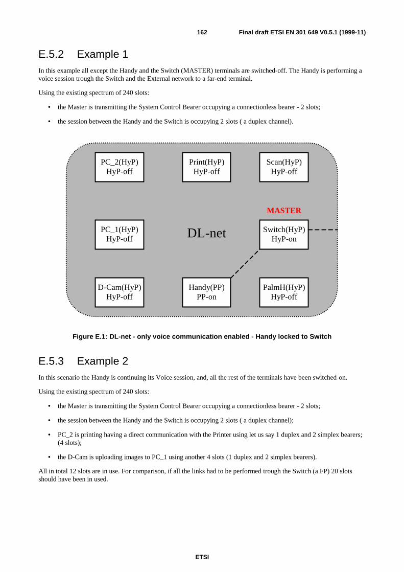
ETSI
Final draft ETSI EN 301 649 V0.5.1 (1999-11)162
E.5.2 Example 1In this example all except the Handy and the Switch (MASTER) terminals are switched-off. The Handy is performing avoice session trough the Switch and the External network to a far-end terminal.
Using the existing spectrum of 240 slots:
• the Master is transmitting the System Control Bearer occupying a connectionless bearer - 2 slots;
• the session between the Handy and the Switch is occupying 2 slots ( a duplex channel).
PC_1(HyP)HyP-off
PC_2(HyP)HyP-off
Print(HyP)HyP-off
Scan(HyP)HyP-off
D-Cam(HyP)HyP-off
Handy(PP)PP-on
Switch(HyP)HyP-on
PalmH(HyP)HyP-off
DL-net
MASTER
Figure E.1: DL-net - only voice communication enabled - Handy locked to Switch
E.5.3 Example 2In this scenario the Handy is continuing its Voice session, and, all the rest of the terminals have been switched-on.
Using the existing spectrum of 240 slots:
• the Master is transmitting the System Control Bearer occupying a connectionless bearer - 2 slots;
• the session between the Handy and the Switch is occupying 2 slots ( a duplex channel);
• PC_2 is printing having a direct communication with the Printer using let us say 1 duplex and 2 simplex bearers;(4 slots);
• the D-Cam is uploading images to PC_1 using another 4 slots (1 duplex and 2 simplex bearers).
All in total 12 slots are in use. For comparison, if all the links had to be performed trough the Switch (a FP) 20 slotsshould have been in used.
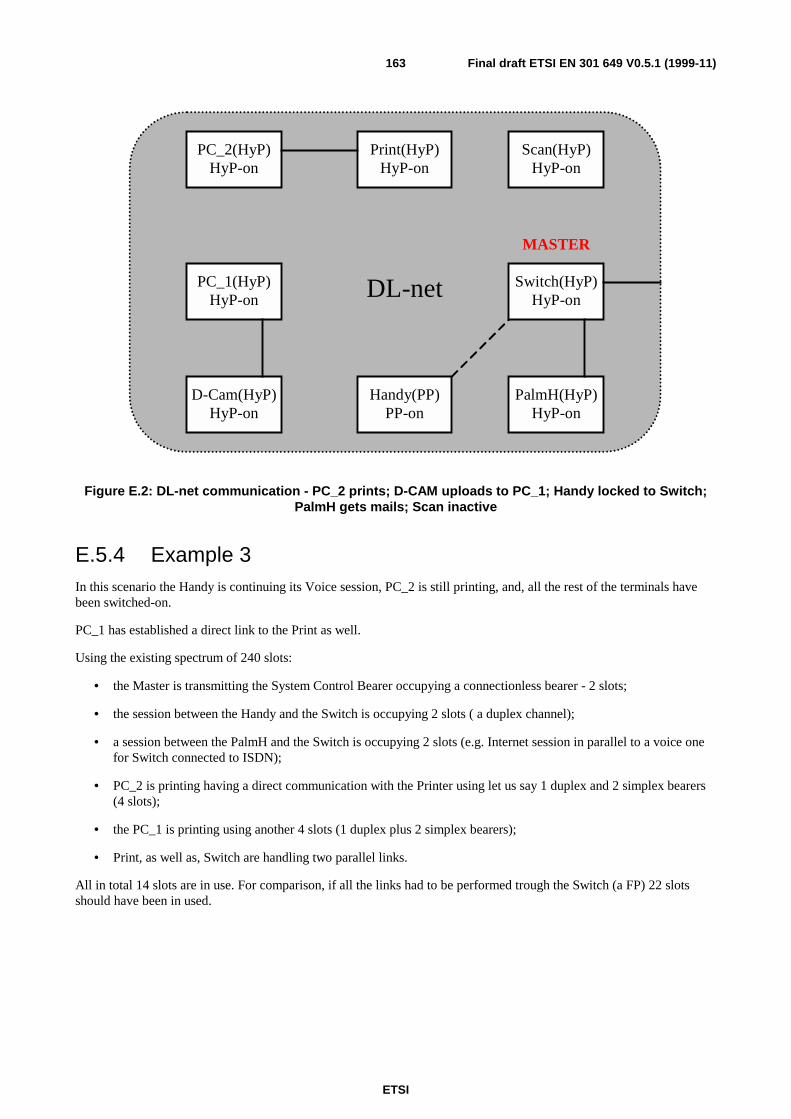
ETSI
Final draft ETSI EN 301 649 V0.5.1 (1999-11)163
PC_1(HyP)HyP-on
PC_2(HyP)HyP-on
Print(HyP)HyP-on
Scan(HyP)HyP-on
D-Cam(HyP)HyP-on
Handy(PP)PP-on
Switch(HyP)HyP-on
PalmH(HyP)HyP-on
DL-net
MASTER
Figure E.2: DL-net communication - PC_2 prints; D-CAM uploads to PC_1; Handy locked to Switch;PalmH gets mails; Scan inactive
E.5.4 Example 3In this scenario the Handy is continuing its Voice session, PC_2 is still printing, and, all the rest of the terminals havebeen switched-on.
PC_1 has established a direct link to the Print as well.
Using the existing spectrum of 240 slots:
• the Master is transmitting the System Control Bearer occupying a connectionless bearer - 2 slots;
• the session between the Handy and the Switch is occupying 2 slots ( a duplex channel);
• a session between the PalmH and the Switch is occupying 2 slots (e.g. Internet session in parallel to a voice onefor Switch connected to ISDN);
• PC_2 is printing having a direct communication with the Printer using let us say 1 duplex and 2 simplex bearers(4 slots);
• the PC_1 is printing using another 4 slots (1 duplex plus 2 simplex bearers);
• Print, as well as, Switch are handling two parallel links.
All in total 14 slots are in use. For comparison, if all the links had to be performed trough the Switch (a FP) 22 slotsshould have been in used.
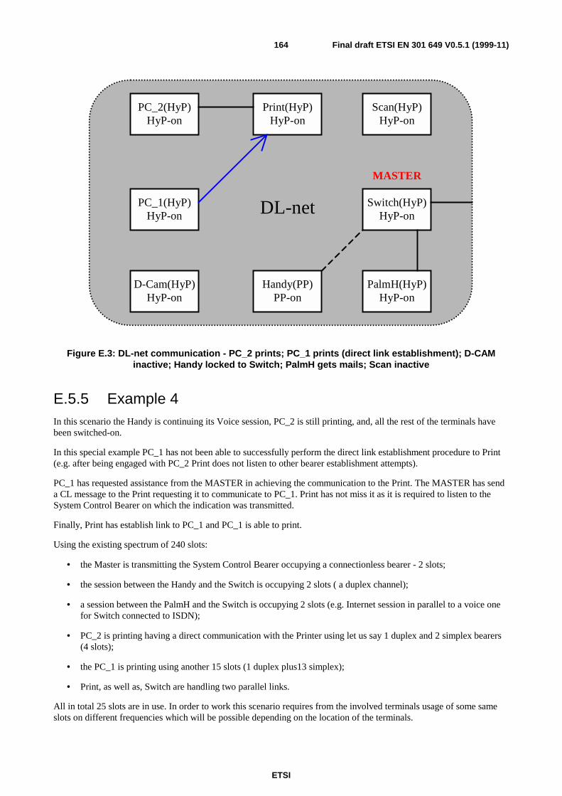
ETSI
Final draft ETSI EN 301 649 V0.5.1 (1999-11)164
PC_1(HyP)HyP-on
PC_2(HyP)HyP-on
Print(HyP)HyP-on
Scan(HyP)HyP-on
D-Cam(HyP)HyP-on
Handy(PP)PP-on
Switch(HyP)HyP-on
PalmH(HyP)HyP-on
DL-net
MASTER
Figure E.3: DL-net communication - PC_2 prints; PC_1 prints (direct link establishment); D-CAMinactive; Handy locked to Switch; PalmH gets mails; Scan inactive
E.5.5 Example 4In this scenario the Handy is continuing its Voice session, PC_2 is still printing, and, all the rest of the terminals havebeen switched-on.
In this special example PC_1 has not been able to successfully perform the direct link establishment procedure to Print(e.g. after being engaged with PC_2 Print does not listen to other bearer establishment attempts).
PC_1 has requested assistance from the MASTER in achieving the communication to the Print. The MASTER has senda CL message to the Print requesting it to communicate to PC_1. Print has not miss it as it is required to listen to theSystem Control Bearer on which the indication was transmitted.
Finally, Print has establish link to PC_1 and PC_1 is able to print.
Using the existing spectrum of 240 slots:
• the Master is transmitting the System Control Bearer occupying a connectionless bearer - 2 slots;
• the session between the Handy and the Switch is occupying 2 slots ( a duplex channel);
• a session between the PalmH and the Switch is occupying 2 slots (e.g. Internet session in parallel to a voice onefor Switch connected to ISDN);
• PC_2 is printing having a direct communication with the Printer using let us say 1 duplex and 2 simplex bearers(4 slots);
• the PC_1 is printing using another 15 slots (1 duplex plus13 simplex);
• Print, as well as, Switch are handling two parallel links.
All in total 25 slots are in use. In order to work this scenario requires from the involved terminals usage of some sameslots on different frequencies which will be possible depending on the location of the terminals.
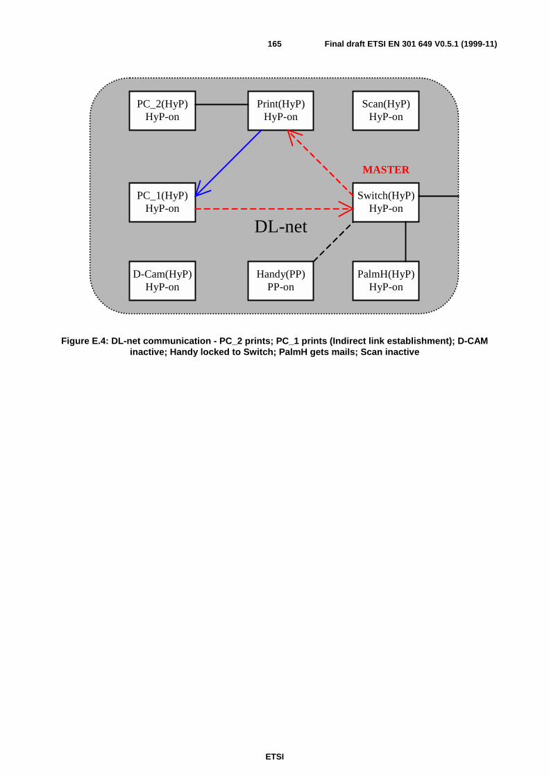
ETSI
Final draft ETSI EN 301 649 V0.5.1 (1999-11)165
PC_1(HyP)HyP-on
PC_2(HyP)HyP-on
Print(HyP)HyP-on
Scan(HyP)HyP-on
D-Cam(HyP)HyP-on
Handy(PP)PP-on
Switch(HyP)HyP-on
PalmH(HyP)HyP-on
DL-net
MASTER
Figure E.4: DL-net communication - PC_2 prints; PC_1 prints (Indirect link establishment); D-CAMinactive; Handy locked to Switch; PalmH gets mails; Scan inactive

ETSI
Final draft ETSI EN 301 649 V0.5.1 (1999-11)166
E.6 Usage of PPs or FPs in DCDL-net
E.6.1 GeneralApart from HyPs terminals, normal PPs and FPs can become members of a DCDL-net.
Such terminals need to support some of the procedures described earlier in the present document. Thissubclause describes the necessary requirements.
E.6.2 Requirements to FPs
E.6.2.1 General
A FP can be a member of a DCDL-net only in the role of a MASTER. To operate as MASTER a FP shall support theprocedures as indicated in the table below.
Table E.17: Support of DCDL-net procedures for a member of type FP
Procedure Support CommentsMembership Access Rights Allocation YES the MASTER related issuesRe-initialization of membership access rights YES the MASTER related issuesMembers Data Transfer YES the MASTER related issuesPresence/Absence Indication YES To understand and handle
initiation of thisBandwidth management YES the MASTER related issuesDirect Link Establishment OPTIONAL to initiate
MANDATORY to responsethe MASTER related issues
Indirect Link Establishment YES the MASTER related issuesMASTER management - MASTER assign YES the MASTER related issuesMASTER management - MASTER Change YES the MASTER related issuesMASTER management - DCDL-net System bearermanagement
YES the MASTER related issues
Common Subscription Database management -RFPI, PARK and PLI
YES the MASTER related issues
Common Subscription Database management -IPUI
YES the MASTER related issues
Common Subscription Database management -TPUI and LAL
YES the MASTER related issues
Common Subscription Database management -Keys
YES the MASTER related issues
Modification to this procedure wherever required are described in the following subclauses.
E.6.2.2 Members Data Transfer
The requirements as in subclause E.3.4 shall apply with the following modification.
A FP can be distinguish from a HyP by the indication in the <Discriminator type>:
Table E.18: Discriminator type for PP
<<IWU-TO-IWU>><Discriminator Type> 0010 FP Information
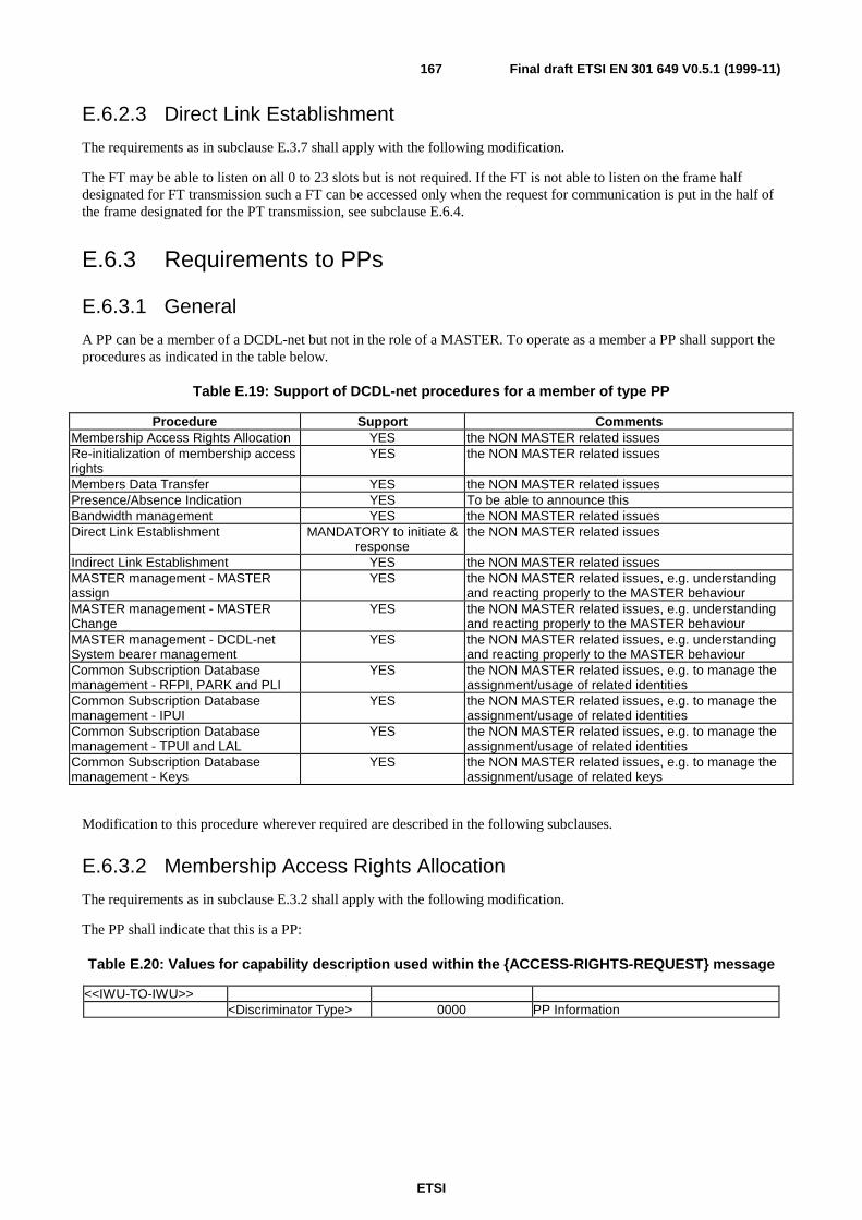
ETSI
Final draft ETSI EN 301 649 V0.5.1 (1999-11)167
E.6.2.3 Direct Link Establishment
The requirements as in subclause E.3.7 shall apply with the following modification.
The FT may be able to listen on all 0 to 23 slots but is not required. If the FT is not able to listen on the frame halfdesignated for FT transmission such a FT can be accessed only when the request for communication is put in the half ofthe frame designated for the PT transmission, see subclause E.6.4.
E.6.3 Requirements to PPs
E.6.3.1 General
A PP can be a member of a DCDL-net but not in the role of a MASTER. To operate as a member a PP shall support theprocedures as indicated in the table below.
Table E.19: Support of DCDL-net procedures for a member of type PP
Procedure Support CommentsMembership Access Rights Allocation YES the NON MASTER related issuesRe-initialization of membership accessrights
YES the NON MASTER related issues
Members Data Transfer YES the NON MASTER related issuesPresence/Absence Indication YES To be able to announce thisBandwidth management YES the NON MASTER related issuesDirect Link Establishment MANDATORY to initiate &
responsethe NON MASTER related issues
Indirect Link Establishment YES the NON MASTER related issuesMASTER management - MASTERassign
YES the NON MASTER related issues, e.g. understandingand reacting properly to the MASTER behaviour
MASTER management - MASTERChange
YES the NON MASTER related issues, e.g. understandingand reacting properly to the MASTER behaviour
MASTER management - DCDL-netSystem bearer management
YES the NON MASTER related issues, e.g. understandingand reacting properly to the MASTER behaviour
Common Subscription Databasemanagement - RFPI, PARK and PLI
YES the NON MASTER related issues, e.g. to manage theassignment/usage of related identities
Common Subscription Databasemanagement - IPUI
YES the NON MASTER related issues, e.g. to manage theassignment/usage of related identities
Common Subscription Databasemanagement - TPUI and LAL
YES the NON MASTER related issues, e.g. to manage theassignment/usage of related identities
Common Subscription Databasemanagement - Keys
YES the NON MASTER related issues, e.g. to manage theassignment/usage of related keys
Modification to this procedure wherever required are described in the following subclauses.
E.6.3.2 Membership Access Rights Allocation
The requirements as in subclause E.3.2 shall apply with the following modification.
The PP shall indicate that this is a PP:
Table E.20: Values for capability description used within the {ACCESS-RIGHTS-REQUEST} message
<<IWU-TO-IWU>><Discriminator Type> 0000 PP Information
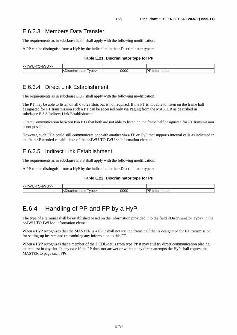
ETSI
Final draft ETSI EN 301 649 V0.5.1 (1999-11)168
E.6.3.3 Members Data Transfer
The requirements as in subclause E.3.4 shall apply with the following modification.
A PP can be distinguish from a HyP by the indication in the <Discriminator type>:
Table E.21: Discriminator type for PP
<<IWU-TO-IWU>><Discriminator Type> 0000 PP Information
E.6.3.4 Direct Link Establishment
The requirements as in subclause E.3.7 shall apply with the following modification.
The PT may be able to listen on all 0 to 23 slots but is not required. If the PT is not able to listen on the frame halfdesignated for PT transmission such a PT can be accessed only via Paging from the MASTER as described insubclause E.3.8 Indirect Link Establishment.
Direct Communication between two PTs that both are not able to listen on the frame half designated for PT transmissionis not possible.
However, such PT s could still communicate one with another via a FP or HyP that supports internal calls as indicated inthe field <Extended capabilities> of the <<IWU-TO-IWU>> information element.
E.6.3.5 Indirect Link Establishment
The requirements as in subclause E.3.8 shall apply with the following modification.
A PP can be distinguish from a HyP by the indication in the <Discriminator type>:
Table E.22: Discriminator type for PP
<<IWU-TO-IWU>><Discriminator Type> 0000 PP Information
E.6.4 Handling of PP and FP by a HyPThe type of a terminal shall be established based on the information provided into the field <Discriminator Type> in the<<IWU-TO-IWU>> information element.
When a HyP recognizes that the MASTER is a FP it shall not use the frame half that is designated for FT transmissionfor setting-up bearers and transmitting any information to this FT.
When a HyP recognizes that a member of the DCDL-net is from type PP it may still try direct communication placingthe request in any slot. In any case if the PP does not answer or without any direct attempts the HyP shall request theMASTER to page such PPs.

ETSI
Final draft ETSI EN 301 649 V0.5.1 (1999-11)169
History
Document history
V0.0.2 March 1999 Public Enquiry PE 9927: 1999-03-05 to 1999-07-02
V0.5.1 November 1999 Vote V 200001: 1999-11-08 to 2000-01-07


![ETSI EN 301 489-15 V2.1...ETSI 7 ETSI EN 301 489-15 V2.1.1 (2016-11) 1 Scope The present document, together with ETSI EN 301 489-1 [1], covers the assessment of commercially available](https://static.fdocuments.us/doc/165x107/5f2db8b1264c1574960889e1/etsi-en-301-489-15-v21-etsi-7-etsi-en-301-489-15-v211-2016-11-1-scope-the.jpg)


![Draft ETSI EN 301 489-9 V2.1...2000/02/01 · ETSI 6 Draft ETSI EN 301 489-9 V2.1.0 (2016-09) 1 Scope The present document, together with ETSI EN 301 489-1 [1], covers the assessment](https://static.fdocuments.us/doc/165x107/606a6768dee68d6bb84c1cb0/draft-etsi-en-301-489-9-v21-20000201-etsi-6-draft-etsi-en-301-489-9-v210.jpg)

