ETSI EN 301 473 V1.4 · ETSI 2 ETSI EN 301 473 V1.4.1 (2013-03) Reference REN/SES-00325 Keywords...
73
ETSI EN 301 473 V1.4.1 (2013-03) Satellite Earth Stations and Systems (SES); Aircraft Earth Stations (AES) operating below 3 GHz under the Aeronautical Mobile Satellite Service (AMSS)/ Mobile Satellite Service (MSS) and/or the Aeronautical Mobile Satellite on Route Service (AMS(R)S)/ Mobile Satellite Service (MSS) European Standard
Transcript of ETSI EN 301 473 V1.4 · ETSI 2 ETSI EN 301 473 V1.4.1 (2013-03) Reference REN/SES-00325 Keywords...

ETSI EN 301 473 V1.4.1 (2013-03)
Satellite Earth Stations and Systems (SES); Aircraft Earth Stations (AES) operating below 3 GHz under the
Aeronautical Mobile Satellite Service (AMSS)/ Mobile Satellite Service (MSS) and/or the
Aeronautical Mobile Satellite on Route Service (AMS(R)S)/ Mobile Satellite Service (MSS)
European Standard

ETSI
ETSI EN 301 473 V1.4.1 (2013-03) 2
Reference REN/SES-00325
Keywords aeronautical, AMSS, earth station, mobile, MSS,
satellite
ETSI
650 Route des Lucioles F-06921 Sophia Antipolis Cedex - FRANCE
Tel.: +33 4 92 94 42 00 Fax: +33 4 93 65 47 16
Siret N° 348 623 562 00017 - NAF 742 C
Association à but non lucratif enregistrée à la Sous-Préfecture de Grasse (06) N° 7803/88
Important notice
Individual copies of the present document can be downloaded from: http://www.etsi.org
The present document may be made available in more than one electronic version or in print. In any case of existing or perceived difference in contents between such versions, the reference version is the Portable Document Format (PDF).
In case of dispute, the reference shall be the printing on ETSI printers of the PDF version kept on a specific network drive within ETSI Secretariat.
Users of the present document should be aware that the document may be subject to revision or change of status. Information on the current status of this and other ETSI documents is available at
http://portal.etsi.org/tb/status/status.asp
If you find errors in the present document, please send your comment to one of the following services: http://portal.etsi.org/chaircor/ETSI_support.asp
Copyright Notification
No part may be reproduced except as authorized by written permission. The copyright and the foregoing restriction extend to reproduction in all media.
© European Telecommunications Standards Institute 2013.
All rights reserved.
DECTTM, PLUGTESTSTM, UMTSTM and the ETSI logo are Trade Marks of ETSI registered for the benefit of its Members. 3GPPTM and LTE™ are Trade Marks of ETSI registered for the benefit of its Members and
of the 3GPP Organizational Partners. GSM® and the GSM logo are Trade Marks registered and owned by the GSM Association.

ETSI
ETSI EN 301 473 V1.4.1 (2013-03) 3
Contents
Intellectual Property Rights ................................................................................................................................ 8
Foreword ............................................................................................................................................................. 8
Introduction ........................................................................................................................................................ 8
1 Scope ........................................................................................................................................................ 9
2 References ................................................................................................................................................ 9
2.1 Normative references ......................................................................................................................................... 9
2.2 Informative references ...................................................................................................................................... 10
3 Definitions and abbreviations ................................................................................................................. 10
3.1 Definitions ........................................................................................................................................................ 10
3.2 Abbreviations ................................................................................................................................................... 11
4 General ................................................................................................................................................... 12
4.1 Presentation of equipment for testing purposes ................................................................................................ 12
4.2 Aircraft earth stations ....................................................................................................................................... 12
4.3 Description of equipment ................................................................................................................................. 13
5 Requirements for AES transmitting in the band 1 610 MHz to 1 626,5 MHz ....................................... 14
5.1 Unwanted emissions limits outside the band 1 610 MHz to 1 626,5 MHz and the band 1 626,5 MHz to 1 628,5 MHz (carrier-on) ................................................................................................................................. 14
5.1.1 Purpose ....................................................................................................................................................... 14
5.1.2 Conformance requirements ......................................................................................................................... 14
5.1.3 Method of test ............................................................................................................................................. 14
5.1.4 Peak measurement ...................................................................................................................................... 15
5.1.5 Average measurement ................................................................................................................................. 15
5.1.6 Test requirements ........................................................................................................................................ 16
5.2 Unwanted emissions limits within the band 1 610 MHz to 1 626,5 MHz and the band 1 626,5 MHz to 1 628,5 MHz (carrier-on) ................................................................................................................................. 16
5.2.1 Purpose ....................................................................................................................................................... 16
5.2.2 Conformance requirements ......................................................................................................................... 16
5.2.3 Method of test ............................................................................................................................................. 17
5.2.4 Measurement method .................................................................................................................................. 18
5.2.5 Test requirements ........................................................................................................................................ 18
5.3 EIRP density limits within the operational band .............................................................................................. 18
5.3.1 Purpose ....................................................................................................................................................... 18
5.3.2 Conformance requirements ......................................................................................................................... 18
5.3.3 Method of test ............................................................................................................................................. 19
5.3.4 Peak Limit Test ........................................................................................................................................... 19
5.3.5 Mean Limit Test ......................................................................................................................................... 19
5.3.6 Test requirements ........................................................................................................................................ 20
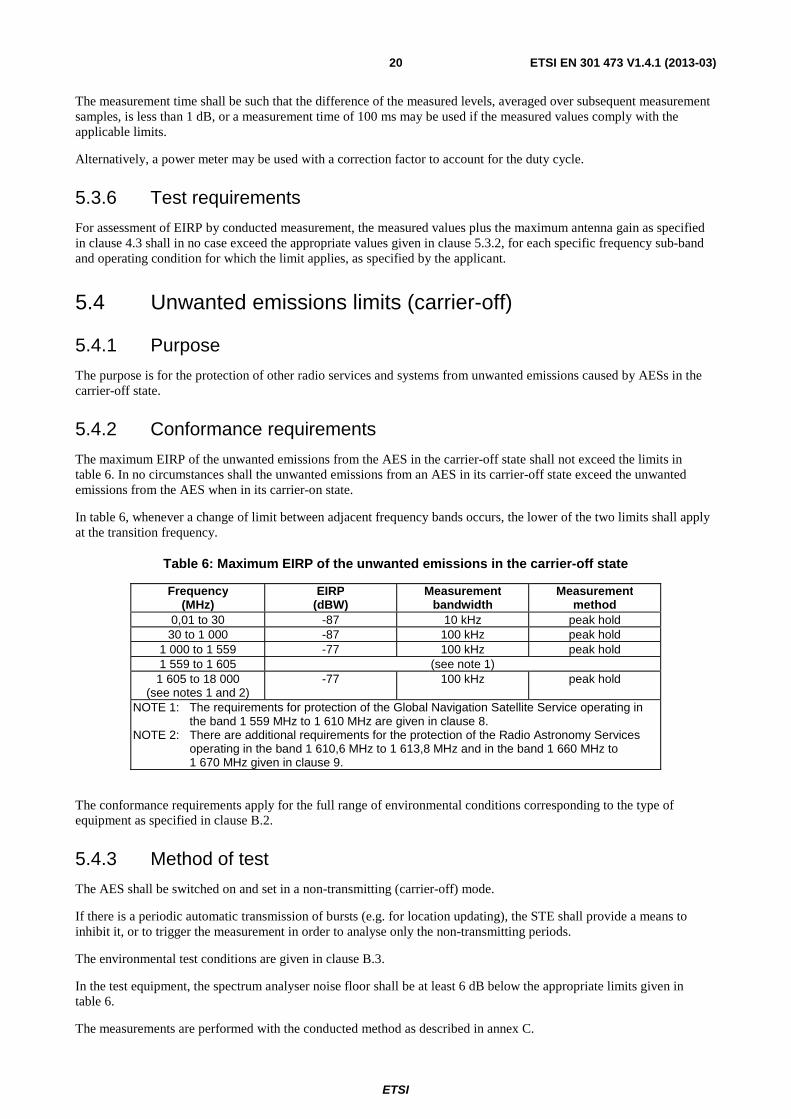
5.4 Unwanted emissions limits (carrier-off) ........................................................................................................... 20
5.4.1 Purpose ....................................................................................................................................................... 20
5.4.2 Conformance requirements ......................................................................................................................... 20
5.4.3 Method of test ............................................................................................................................................. 20
5.4.4 Peak measurement ...................................................................................................................................... 21
5.4.5 Average measurement ................................................................................................................................. 21
5.4.6 Test requirements ........................................................................................................................................ 21
5.5 AES Control and Monitoring Functions (CMF) ............................................................................................... 21
5.5.1 Special test equipment ................................................................................................................................ 21
5.5.2 Self-monitoring functions ........................................................................................................................... 22
5.5.2.1 Processor monitoring ............................................................................................................................ 22
5.5.2.1.1 Purpose ............................................................................................................................................ 22
5.5.2.1.2 Conformance requirements .............................................................................................................. 22
5.5.2.1.3 Method of test .................................................................................................................................. 22
5.5.2.2 Transmit frequency generation sub-system monitoring ........................................................................ 22
5.5.2.2.1 Purpose ............................................................................................................................................ 22

ETSI
ETSI EN 301 473 V1.4.1 (2013-03) 4
5.5.2.2.2 Conformance requirements .............................................................................................................. 22
5.5.2.2.3 Method of test .................................................................................................................................. 22
5.5.3 Network control authorization and reception .............................................................................................. 22
5.5.3.1 Network control authorization .............................................................................................................. 22
5.5.3.1.1 Purpose ............................................................................................................................................ 22
5.5.3.1.2 Conformance requirements .............................................................................................................. 23
5.5.3.1.3 Method of test .................................................................................................................................. 23
5.5.3.1.4 Test procedure ................................................................................................................................. 23
5.5.3.1.5 Test requirement .............................................................................................................................. 23
5.5.3.2 Network control reception transmit frequency control.......................................................................... 23
5.5.3.2.1 Purpose ............................................................................................................................................ 23
5.5.3.2.2 Conformance requirements .............................................................................................................. 24
5.5.3.2.3 Method of test .................................................................................................................................. 24
5.5.3.2.4 Test procedure ................................................................................................................................. 24
5.5.3.2.5 Test requirement .............................................................................................................................. 24
5.6 Equipment identity ........................................................................................................................................... 24
5.6.1 Purpose ....................................................................................................................................................... 24
5.6.2 Conformance requirements ......................................................................................................................... 24
5.6.3 Method of test ............................................................................................................................................. 25
5.6.4 Test procedure ............................................................................................................................................ 25
5.6.5 Test requirements ........................................................................................................................................ 25
6 Requirements for AES transmitting in the band 1 626,5 MHz to 1 660,5 MHz and the band 1 668,0 MHz to 1 675,0 MHz ................................................................................................................ 25
6.1 Unwanted emissions limits outside the band 1 626,5 MHz to 1 660,5 MHz and the band 1 660,5 MHz to 1 662,5 MHz and also outside the band 1 666,0 MHz to 1 668,0 MHz, the band 1 668,0 MHz to 1 675,0 MHz and the band 1 675,0 MHz to 1 677,0 MHz ............................................................................................ 25
6.1.1 Purpose ....................................................................................................................................................... 25
6.1.2 Conformance requirements ......................................................................................................................... 26
6.1.3 Testing for carrier on state .......................................................................................................................... 32
6.1.3.1 Method of test ....................................................................................................................................... 32
6.1.3.2 Measurement method ............................................................................................................................ 33
6.1.3.3 Test requirements .................................................................................................................................. 33
6.1.4 Testing for carrier off state ......................................................................................................................... 33
6.1.4.1 Method of test ....................................................................................................................................... 33
6.1.4.2 Peak measurement method .................................................................................................................... 34
6.1.4.3 Average measurement ........................................................................................................................... 34
6.1.4.4 Test requirements .................................................................................................................................. 34
6.2 Unwanted emissions limits within the band 1 626,5 MHz to 1 660,5 MHz and the band 1 660,5 MHz to 1 662,5 MHz and also within the band 1 666,0 MHz to 1 668,0 MHz, the band 1 668,0 MHz to 1 675,0 MHz and the band 1 675,0 MHz to 1 677,0 MHz ............................................................................................ 35
6.2.1 Purpose ....................................................................................................................................................... 35
6.2.2 Conformance requirements ......................................................................................................................... 35
6.2.2.1 General .................................................................................................................................................. 35
6.2.2.2 Specification 1: Carrier-on state ............................................................................................................ 35
6.2.2.3 Specification 2: Carrier-off state ........................................................................................................... 38
6.2.3 Testing for carrier on state .......................................................................................................................... 38
6.2.3.1 Method of test ....................................................................................................................................... 38
6.2.3.2 Measurement method ............................................................................................................................ 39
6.2.3.3 Test requirements .................................................................................................................................. 39
6.2.4 Testing for carrier off state ......................................................................................................................... 39
6.2.4.1 Method of test ....................................................................................................................................... 39
6.2.4.2 Peak measurement method .................................................................................................................... 40
6.2.4.3 Average measurement ........................................................................................................................... 40
6.2.4.4 Test requirements .................................................................................................................................. 40
6.3 AES Control and Monitoring Functions (CMF) ............................................................................................... 40
6.3.1 Special test equipment ................................................................................................................................ 40
6.3.2 Self-monitoring functions ........................................................................................................................... 41
6.3.2.1 Processor monitoring ............................................................................................................................ 41
6.3.2.1.1 Purpose ............................................................................................................................................ 41
6.3.2.1.2 Conformance requirements .............................................................................................................. 41
6.3.2.1.3 Method of test .................................................................................................................................. 41

ETSI
ETSI EN 301 473 V1.4.1 (2013-03) 5
6.3.2.2 Transmit frequency generation sub-system monitoring ........................................................................ 41
6.3.2.2.1 Purpose ............................................................................................................................................ 41
6.3.2.2.2 Conformance requirements .............................................................................................................. 41
6.3.2.2.3 Method of test .................................................................................................................................. 41
6.3.3 Network control authorization and reception .............................................................................................. 41
6.3.3.1 Network control authorization .............................................................................................................. 41
6.3.3.1.1 Purpose ............................................................................................................................................ 41
6.3.3.1.2 Conformance requirements .............................................................................................................. 42
6.3.3.1.3 Method of test .................................................................................................................................. 42
6.3.3.1.4 Test procedure ................................................................................................................................. 42
6.3.3.1.5 Test requirement .............................................................................................................................. 42
6.3.3.2 Network control reception transmit frequency control.......................................................................... 42
6.3.3.2.1 Purpose ............................................................................................................................................ 42
6.3.3.2.2 Conformance requirements .............................................................................................................. 43
6.3.3.2.3 Method of test .................................................................................................................................. 43
6.3.3.2.4 Test procedure ................................................................................................................................. 43
6.3.3.2.5 Test requirement .............................................................................................................................. 43
6.4 Equipment identity ........................................................................................................................................... 43
6.4.1 Purpose ....................................................................................................................................................... 43
6.4.2 Conformance requirements ......................................................................................................................... 43
6.4.3 Method of test ............................................................................................................................................. 44
6.4.4 Test procedure ............................................................................................................................................ 44
6.4.5 Test requirements ........................................................................................................................................ 44
7 Requirements for NGSO AES transmitting in the band 1 980 MHz to 2 010 MHz .............................. 44
7.1 Unwanted emissions limits outside the band 1 980,1 MHz to 2 009,9 MHz (carrier-on) ................................ 44
7.1.1 Purpose ....................................................................................................................................................... 44
7.1.2 Conformance requirements ......................................................................................................................... 44
7.1.3 Method of test ............................................................................................................................................. 45
7.1.4 Peak measurement ...................................................................................................................................... 46
7.1.5 Average measurement ................................................................................................................................. 46
7.1.6 Test requirements ........................................................................................................................................ 46
7.2 Unwanted emissions limits within the bands 1 980,1 MHz to 2 009,9 MHz, 1 978,1 MHz to 1 980,1 MHz and 2 009,9 MHz to 2 011,9 MHz (carrier-on)........................................................................... 46
7.2.1 Purpose ....................................................................................................................................................... 46
7.2.2 Conformance requirements ......................................................................................................................... 47
7.2.3 Method of test ............................................................................................................................................. 47
7.2.4 Measurement method .................................................................................................................................. 48
7.2.5 Test requirements ........................................................................................................................................ 48
7.3 Unwanted emissions limits (carrier-off) ........................................................................................................... 48
7.3.1 Purpose ....................................................................................................................................................... 48
7.3.2 Conformance requirements ......................................................................................................................... 48
7.3.3 Method of test ............................................................................................................................................. 49
7.3.4 Peak measurement ...................................................................................................................................... 49
7.3.5 Average measurement ................................................................................................................................. 49
7.3.6 Test requirements ........................................................................................................................................ 50
7.4 AES Control and Monitoring Functions (CMF) ............................................................................................... 50
7.4.1 Special test equipment ................................................................................................................................ 50
7.4.2 Self-monitoring functions ........................................................................................................................... 50
7.4.2.1 Processor monitoring ............................................................................................................................ 50
7.4.2.1.1 Purpose ............................................................................................................................................ 50
7.4.2.1.2 Conformance requirements .............................................................................................................. 50
7.4.2.1.3 Method of test .................................................................................................................................. 50
7.4.2.2 Transmit frequency generation sub-system monitoring ........................................................................ 50
7.4.2.2.1 Purpose ............................................................................................................................................ 50
7.4.2.2.2 Conformance requirements .............................................................................................................. 51
7.4.2.2.3 Method of test .................................................................................................................................. 51
7.4.3 Network control authorization and reception .............................................................................................. 51
7.4.3.1 Network control authorization .............................................................................................................. 51
7.4.3.1.1 Purpose ............................................................................................................................................ 51
7.4.3.1.2 Conformance requirements .............................................................................................................. 51
7.4.3.1.3 Method of test .................................................................................................................................. 51

ETSI
ETSI EN 301 473 V1.4.1 (2013-03) 6
7.4.3.1.4 Test procedure ................................................................................................................................. 51
7.4.3.1.5 Test requirement .............................................................................................................................. 52
7.4.3.2 Network control reception ..................................................................................................................... 52
7.4.3.2.1 Transmit frequency control ............................................................................................................. 52
7.5 Equipment identity ........................................................................................................................................... 53
7.5.1 Purpose ....................................................................................................................................................... 53
7.5.2 Conformance requirements ......................................................................................................................... 53
7.5.3 Method of test ............................................................................................................................................. 53
7.5.4 Test procedure ............................................................................................................................................ 53
7.5.5 Test requirements ........................................................................................................................................ 53
8 Protection of the global navigation satellite service operating in the band 1 559 MHz to 1 610 MHz .............................................................................................................................................. 54
8.1 1 559 MHz to 1 605 MHz ................................................................................................................................ 54
8.1.1 Purpose ....................................................................................................................................................... 54
8.1.2 Conformance requirements ......................................................................................................................... 54
8.2 1 605 MHz to 1 610 MHz ................................................................................................................................ 54
8.2.1 Purpose ....................................................................................................................................................... 54
8.2.2 Conformance requirements ......................................................................................................................... 54
8.3 Method of test ................................................................................................................................................... 55
8.4 Average measurement ...................................................................................................................................... 55
8.5 Test requirements ............................................................................................................................................. 55
9 Protection of the radio astronomy services operating in the band 1 610,6 MHz to 1 613,8 MHz and in the band 1 660 MHz to 1 670 MHz ............................................................................................. 56
9.1 Purpose ............................................................................................................................................................. 56
9.2 Conformance requirements .............................................................................................................................. 56
9.2.1 Alternative 1 ............................................................................................................................................... 56
9.2.2 Alternative 2 ............................................................................................................................................... 57
9.2.3 Protection of the radio astronomy service in the 1 660,0 MHz to 1 670,0 MHz band ................................ 57
9.3 Method of test - unwanted emissions (alternative 1) ........................................................................................ 57
9.4 Test procedure - unwanted emissions (alternative 1) ....................................................................................... 57
9.5 Test requirement - unwanted emissions (alternative 1) .................................................................................... 58
9.6 Method of test - CMF function (alternative 2) ................................................................................................. 58
9.7 Test procedure- CMF function (alternative 2) .................................................................................................. 58
9.8 Test requirement- CMF function (alternative 2) .............................................................................................. 59
Annex A (normative): General test requirements ............................................................................. 60
A.1 AES test modes ...................................................................................................................................... 60
A.2 Special Test Equipment .......................................................................................................................... 60
A.2.1 STE description ................................................................................................................................................ 60
A.2.2 Use of STE for control and monitoring functions tests .................................................................................... 61
A.2.3 Test modulating signal ..................................................................................................................................... 61
A.3 Laboratory Test Equipment .................................................................................................................... 62
A.4 Interpretation of the measurement results .............................................................................................. 62
A.5 Test report .............................................................................................................................................. 62
Annex B (normative): Environmental conditions ............................................................................. 63
B.1 General ................................................................................................................................................... 63
B.2 Environmental conformance requirements............................................................................................. 63
B.3 Environmental test conditions ................................................................................................................ 63
Annex C (normative): Arrangements for measurement of emissions from AES ........................... 64
C.1 General ................................................................................................................................................... 64
C.2 Carrier-on emissions............................................................................................................................... 64
C.2.1 Equipment required .......................................................................................................................................... 64

ETSI
ETSI EN 301 473 V1.4.1 (2013-03) 7
C.2.2 Equipment arrangement ................................................................................................................................... 65
C.2.3 Emissions from 4 GHz to 18 GHz .................................................................................................................... 65
C.2.4 Emissions from 10 kHz to 4 GHz ..................................................................................................................... 65
C.3 Carrier-off emissions .............................................................................................................................. 66
C.3.1 Equipment required .......................................................................................................................................... 66
C.3.2 Equipment arrangement ................................................................................................................................... 66
C.3.3 Carrier-off emissions from 4 GHz to 18 GHz .................................................................................................. 66
C.3.4 Carrier-off emissions from 10 kHz to 4 GHz ................................................................................................... 67
Annex D (informative): Explanation of nominated bandwidth .......................................................... 68
D.1 Introduction ............................................................................................................................................ 68
D.2 Interpretation of Parameters [Bn, fc, a, b] ............................................................................................... 68
D.3 Choice of nominated bandwidth ............................................................................................................. 68
D.4 Maximum value for nominated bandwidth ............................................................................................ 70
Annex E (informative): Bibliography ................................................................................................... 72
History .............................................................................................................................................................. 73
ETSI
ETSI EN 301 473 V1.4.1 (2013-03) 8
Intellectual Property Rights IPRs essential or potentially essential to the present document may have been declared to ETSI. The information pertaining to these essential IPRs, if any, is publicly available for ETSI members and non-members, and can be found in ETSI SR 000 314: "Intellectual Property Rights (IPRs); Essential, or potentially Essential, IPRs notified to ETSI in respect of ETSI standards", which is available from the ETSI Secretariat. Latest updates are available on the ETSI Web server (http://ipr.etsi.org).
Pursuant to the ETSI IPR Policy, no investigation, including IPR searches, has been carried out by ETSI. No guarantee can be given as to the existence of other IPRs not referenced in ETSI SR 000 314 (or the updates on the ETSI Web server) which are, or may be, or may become, essential to the present document.
Foreword This European Standard (EN) has been produced by ETSI Technical Committee Satellite Earth Stations and Systems (SES).
National transposition dates
Date of adoption of this EN: 22 February 2013
Date of latest announcement of this EN (doa): 31 May 2013
Date of latest publication of new National Standard or endorsement of this EN (dop/e):
30 November 2013
Date of withdrawal of any conflicting National Standard (dow): 30 November 2013
Introduction An AES to be effectively used on board an aircraft will also be subject to airworthiness approval. This approval will refer to additional requirements (e.g. ISO 7137 equivalent to EUROCAE ED-14D and RTCA DO-160D [1]). Foreseeable evolution of the GNSS (i.e. Galileo or GPS L5) would result in the coming years in specific requirements to protect the use of the GNSS signals on board aircraft. Therefore these new GNSS frequency bands may require different protection than currently stated in the present document.

ETSI
ETSI EN 301 473 V1.4.1 (2013-03) 9
1 Scope The present document specifies certain minimum technical performance requirements of Aircraft Earth Station (AES) equipment with both transmit and receive capabilities for operation in the Aeronautical Mobile Satellite Service (AMSS)/Mobile Satellite Service (MSS), and/or in the Aeronautical Mobile Satellite on Route Service (AMS(R)S)/Mobile Satellite Service (MSS), in the frequency bands given in table 1.
Table 1: Aeronautical Mobile Satellite Service (AMSS)/Mobile Satellite Service (MSS), and/or Aeronautical Mobile Satellite on Route Service (AMS(R)S)/
Mobile Satellite Service (MSS) frequency bands
AMSS/MSS and/or AMS(R)S/MSS frequency bands AES transmit 1 610 MHz to 1 626,5 MHz AES receive 1 613,8 MHz to 1 626,5 MHz AES receive 2 483,5 MHz to 2 500 MHz AES transmit 1 626,5 MHz to 1 660,5 MHz AES receive 1 525 MHz to 1 559 MHz AES transmit 1 668 MHz to 1 675 MHz AES receive 1 518 MHz to 1 525 MHz AES transmit 1 980 MHz to 2 010 MHz AES receive 2 170 MHz to 2 200 MHz
The technical requirements in the present document are in two major categories:
• emission limits: to protect other radio services and systems from harmful interference generated by the AES in normal use;
• AES Control and Monitoring Functions (CMF): to protect other radio services and systems from unwanted transmissions from the AES. The CMF in each AES is capable of answering to commands from the Network Control Facilities (NCF) for its supporting satellite network.
NOTE: The requirements for Network Control Facilities (NCF) for S-PCN MES transmitting in the 1 610 MHz to 1 626,5 MHz band or the 1 980 MHz to 2 010 MHz band are contained in ETS 300 735 [4]; these requirements are also applicable to AES transmitting in those bands.
An AES may be subject to additional or alternative requirements in other standards depending on its functionality, in particular if it supports a service which is considered a justified case for regulation of terminal equipment interworking via the public telecommunications network. An AES will also be subject to additional airworthiness certification requirements.
2 References References are either specific (identified by date of publication and/or edition number or version number) or non-specific. For specific references, only the cited version applies. For non-specific references, the latest version of the reference document (including any amendments) applies.
Referenced documents which are not found to be publicly available in the expected location might be found at http://docbox.etsi.org/Reference.
NOTE: While any hyperlinks included in this clause were valid at the time of publication, ETSI cannot guarantee their long term validity.
2.1 Normative references The following referenced documents are necessary for the application of the present document.
[1] ISO 7137 equivalent to EUROCAE ED-14D and RTCA DO-160D: "Aircraft - Environmental conditions and test procedures for airborne equipment".

ETSI
ETSI EN 301 473 V1.4.1 (2013-03) 10
[2] ITU-T Recommendation O.153 (1992): "Basic parameters for the measurement of error performance at bit rates below the primary rate".
[3] RTCA DO-210D: "Minimum Operational Performance Standards (MOPS) for Geosynchronous Orbit Aeronautical Mobile Satellite Services (AMSS) Avionics".
[4] ETSI ETS 300 735: "Satellite Personal Communications Networks (S-PCN); Network Control Facilities (NCF) for Mobile Earth Stations (MES), including handheld earth stations, for S-PCN in the 1,6/2,4 GHz and the 2,0 GHz bands, providing voice and/or data communications under the Mobile Satellite Service (MSS)".
[5] ITU Radio Regulations 2008.
2.2 Informative references The following referenced documents are not necessary for the application of the present document but they assist the user with regard to a particular subject area.
[i.1] ECC/DEC (04)09: "ECC Decision of 12 November 2004 on the designation of the band 1518 to 1525 MHz and 1670 to 1675 MHz for the Mobile-Satellite Service".
[i.2] Annex 10 Volume III - AMSS and AMS(R)S specific sections (Aeronautical Telecommunications) to the convention on International Civil Aviation (ICAO annex 10).
3 Definitions and abbreviations
3.1 Definitions For the purposes of the present document, the following terms and definitions apply:
antenna subsystem: includes all those RF components from the physical aperture of the antenna(s) to a single antenna port where the interconnecting cable to the transceiver is to be attached; and related ancillary components; e.g. beam-steering units and RF relays, if present
applicant: party seeking an approval, or to place an AES on the European market, i.e. the manufacturer of the equipment, or his authorized representative, or an equipment supplier to the European market
carrier-on state (allocated a channel): state when AES is transmitting a signal in a continuous or non-continuous mode
carrier-off state (idle mode): state when AES is powered on but not transmitting a signal, i.e. not in the carrier-on state
conducted measurement: measurement of emissions from an antenna port of the AES made by direct wired connection to the port
Effective Isotropically Radiated Power (EIRP): product of transmitter power and maximum antenna gain, equivalent to an isotropic source radiating uniformly in all directions
Externally Mounted Equipment (EME): IE module which is intended to be externally mounted, as declared by the manufacturer
Installable Equipment (IE): equipment which is intended to be fitted to an aircraft
Internally Mounted Equipment (IME): IE module which is not defined as Externally Mounted Equipment (EME)
Laboratory Test Equipment (LTE): logical grouping that contains the standard test equipment provided by a test laboratory
MSS band: continuous range of frequencies allocated by the ITU to the MSS

ETSI
ETSI EN 301 473 V1.4.1 (2013-03) 11
narrow-band system: system in which the nominal carrier frequency spacing for AESs in the Earth-to-Space direction is less than 300 kHz
network control channel: channel by which an AES receives general control information from the NCF of its network
NCF control message: message, normally originating from a network, to a specified terminal or set of terminals of the network which indicates to the terminal or set of terminals that it/they should carry out some specific action or should enter or maintain some specific state
NOTE: For test purposes NCF control messages may originate from Special Test Equipment.
nominated Bandwidth (Bn): bandwidth of the Aircraft Earth Station (AES) radio frequency transmission
NOTE 1: Bn is wide enough to encompass all spectral elements of the transmission which have a level greater than the specified levels of unwanted emissions. See annex D.
NOTE 2: The Bn is defined relative to the AES actual carrier frequency fc.
Bn is the width of the frequency interval [fc - a, fc + b], where a and b, which is specified by the terminal
manufacturer and may vary with fc.
The frequency interval [fc - a, fc + b] does not encompass more than either:
i) when a = b, 4 nominal carrier frequencies for narrow-band systems; ii) when a ≠ b, 1 nominal carrier frequency for narrow-band systems; or iii) 1 nominal carrier frequency for wideband systems.
The frequency interval [fc - a, fc + b] is within the operational band of the AES.
operational band: sub-portion of an MSS band which has been assigned in the earth-to-space direction to the MSS network within which the AES is operating
radiated measurement: measurement of an actual radiated field
Special Test Equipment (STE): equipment provided by the applicant which allows a test laboratory to control the AES so that the tests required by EN 301 473 can be performed
test laboratory: laboratory which performs conformance testing
test load: substantially non-reactive, non-radiating power attenuator which is capable of safely dissipating the power from the transmitter(s)
transceiver subsystem: subsystem which includes transmitter, receiver and diplexer/LNA (if used) that interfaces at RF at the antenna port where it connects to the interconnecting cable, and with other on-board avionics equipment
unwanted emissions: unwanted emissions are those falling outside the nominated bandwidth in the carrier-on state, and those generated in the carrier-off state
wideband system: system in which the nominal carrier frequency spacing for AESs in the Earth-to-Space direction is equal to or greater than 300 kHz
3.2 Abbreviations For the purposes of the present document, the following abbreviations apply:
AES Aircraft Earth Station AMS(R)S Aeronautical Mobile Satellite on Route Service AMSS Aeronautical Mobile Satellite Service ARINC Aeronautical Radio Inc. Bn nominated Bandwidth CDMA Code Division Multiple Access CMF Control and Monitoring Functions dBW deciBels relative to 1 Watt EIRP Effective Isotropically Radiated Power

ETSI
ETSI EN 301 473 V1.4.1 (2013-03) 12
EME Externally Mounted Equipment EN European Standard ETS European Telecommunications Standard EUROCAE EURopean Organization for Civil Aviation Equipment GES Ground Earth Station GNSS Global Navigation Satellite System HLD HPA and LNA/D HPA High Power Amplifier IE Installable Equipment IME Internally Mounted Equipment ITU International Telecommunications Union LNA/D Low Noise Amplifier/Diplexer LRU Line Replaceable Unit LTE Laboratory Test Equipment MES Mobile Earth Station MIC MES (or AES) unique Identification Code (within its satellite network) MSS Mobile Satellite Service NCF Network Control Facility NGSO Non-Geostationary Satellite Orbit // Non-geostationary Orbit // Non Geo-Synchronous Orbit RA Radio Astronomy RF Radio Frequency RTCA Radio Technical Commission for Aeronautics, a company incorporated in the USA SARP Standard And Recommended Practice SES Satellite Earth Stations and systems S-PCN Satellite-Personal Communications Network STE Special Test Equipment STU Satellite Terminal Unit TDMA Time Division Multiple Access TTE Telecommunications Terminal Equipment
4 General
4.1 Presentation of equipment for testing purposes The applicant may provide to a test laboratory one or more preliminary or production models of the AES equipment, as appropriate, for testing for conformance against the technical requirements of the present document.
If the AES is intended for use with an active antenna, this shall be provided as part of the AES.
If a statement of conformance with the EN is given by the test laboratory on the basis of tests on a preliminary model, then the statement of conformance shall apply to corresponding production models only if they are identical in all technical respects with the preliminary model tested.
4.2 Aircraft earth stations Aircraft Earth Stations are Installable Equipments (IE).
AES for public transport aircraft typically consist of up to four major modules known in the avionics world as Line Replaceable Units (LRU), interconnected by ARINC standard interwiring. These four major modules are:
1) the Satellite Terminal Unit (STU);
2) the High Power Amplifier (HPA);
3) the Low Noise Amplifier/Diplexer (LNA/D);
4) the antenna subsystem.
NOTE: The HPA and LNA/D are sometimes referred to together as the HLD.

ETSI
ETSI EN 301 473 V1.4.1 (2013-03) 13
Items 1, 2 and 3 above, are Internally Mounted Equipments (IME); item 4 above, is an externally mounted equipment (EME).
AES for non-public transport aircraft may have other arrangements.
The control panel for the AES may be part of a unit common with other communications systems on board, or it may be a dedicated, separate unit, or it may be integrated into a self contained AES.
If the control panel is part of a shared communications panel, the control panel and its interwiring are not regarded as part of the AES. However they, or a simulation of them, may be required to activate the AES for test purposes.
In the other cases, the control panel and any interconnecting cables are regarded as part of the AES and are subject to the requirements of the present document.
4.3 Description of equipment The applicant shall provide to the test laboratory a statement which contains all of the information related to the AES and its testing environment which will enable the test laboratory to run an appropriate test suite against the AES.
This shall include:
• AES configuration (description of IME, EME, interconnecting cables);
• for each AES component equipment, the applicable Equipment Categories as defined in ISO 7137 equivalent to EUROCAE ED-14D and RTCA DO-160D [1];
• the method by which the equipment can be switched into its test modes (see note);
• the fault conditions which cause transmission shut-down;
• the maximum antenna gain;
and, if appropriate, at the choice of the applicant:
• the maximum antenna gain at the frequency of particular measured unwanted emissions;
• the multicarrier capability;
• in an information leaflet:
1) the name of the network with which the AES is designed to operate;
2) if applicable, the maximum value of nominated bandwidth for that network, as defined by the network operator;
3) if applicable, the a and b values of the nominated bandwidth for each nominal carrier frequency of the AES;
4) the operating frequency range(s) of the AES;
5) if applicable, the frequency sub-bands and operating conditions for which different EIRP density limits apply;
6) the maximum gross data rate at which the AES is designed to operate;
7) the agreement of the network operator to the above information.
NOTE: If Special Test Equipment (STE) is required see clause A.2.

ETSI
ETSI EN 301 473 V1.4.1 (2013-03) 14
5 Requirements for AES transmitting in the band 1 610 MHz to 1 626,5 MHz
5.1 Unwanted emissions limits outside the band 1 610 MHz to 1 626,5 MHz and the band 1 626,5 MHz to 1 628,5 MHz (carrier-on)
5.1.1 Purpose
The purpose is for the protection of other radio services operating outside the band 1 610 MHz to 1 628,5 MHz from emissions caused by AESs operating within the band 1 610 MHz to 1 626,5 MHz.
5.1.2 Conformance requirements
The maximum EIRP density of the unwanted emissions from the AES outside the band 1 610 MHz to 1 626,5 MHz and the band 1 626,5 MHz to 1 628,5 MHz shall not exceed the limits in table 2.
In table 2, whenever a change of limit between adjacent frequency bands occurs, the lower of the two limits shall apply at the transition frequency.
Table 2: Maximum unwanted emissions outside the band 1 610 MHz to 1 626,5 MHz and the band 1 626,5 MHz to 1 628,5 MHz
Frequency
Carrier-on
(MHz) EIRP (dBW)
Measurement bandwidth
Measurement method
0,01 to 30 -66 10 kHz Peak-hold 30 to 1 000 -66 100 kHz Peak-hold
1 000 to 1 559 -60 1 MHz Average 1 559 to 1 605 (see note 1) 1 605 to 1 610 -70 to -10
(see notes 1 and 2) 1 MHz Average
1 610 to 1 626,5 Not applicable Not applicable Not applicable 1 626,5 to 1 628,5 Not applicable Not applicable Not applicable 1 628,5 to 1 631,5 -60 30 kHz Average 1 631,5 to 1 636,5 -60 100 kHz Average 1 636,5 to 1 646,5 -60 300 kHz Average 1 646,5 to 1 666,5
(see note 3) -60 1 MHz Average
1 666,5 to 2 200 (see note 3)
-60 3 MHz Average
2 200 to 18 000 -60 3 MHz Peak hold NOTE 1: The requirements for protection of the Global Navigation Satellite Service operating in
the band 1 559 MHz to 1 610 MHz are given in clause 8. NOTE 2: Linearly interpolated in dBW versus frequency. NOTE 3: There are additional requirements for the protection of the Radio Astronomy Service
operating in the band 1 660 MHz to 1 670 MHz given in clause 9.
The conformance requirements apply for the full range of environmental conditions corresponding to the type of equipment as specified in clause B.2.
5.1.3 Method of test
This test shall be carried out for the minimum and for the maximum AES transmit frequencies for which the AES is designed to operate, as specified by the applicant.

ETSI
ETSI EN 301 473 V1.4.1 (2013-03) 15
The environmental test conditions are given in clause B.3.
For each test, the AES shall be set to transmit (carrier-on) on one of the specified transmitting frequencies to be tested at its maximum power for that transmit frequency, by means of the STE or by another test facility provided by the applicant.
If there is a handover function in the AES (to allow change of frequency channel during a call), this function shall be disabled.
The transmitted carrier shall be modulated by a test signal at maximum rate as specified in clause A.2.3.
In the test equipment, the spectrum analyser noise floor shall be at least 6 dB below the appropriate limits given in table 2.
The measurements are performed with the conducted method as described in annex C.
5.1.4 Peak measurement
In the case of peak measurement, the spectrum analyser shall be set in sweep mode and shall be operated under the following conditions:
• frequency sweep: as required for frequency range to be assessed;
• resolution bandwidth: measurement bandwidth specified in table 2;
• video bandwidth: at least 3 times the measurement bandwidth;
• averaging: no;
• peak hold: yes.
The sweep time shall be the shortest possible time consistent with proper calibration and ease of operation.
The spectrum analyser shall be stepped over the frequency ranges specified in table 2 for peak measurement.
5.1.5 Average measurement
In the case of average measurement, the spectrum analyser shall be set in sweep mode and shall be operated under the following conditions:
• frequency sweep: as required for frequency range to be assessed;
• resolution bandwidth: measurement bandwidth specified in table 2;
• video bandwidth: equal to the measurement bandwidth;
• averaging: yes;
• peak hold: no.
Unless otherwise stated in table 2, the measurement time shall be such that the difference of the measured levels, averaged over subsequent measurement samples, is less than 1 dB, or a measurement time of 100 ms may be used if the measured values comply with the applicable limits.
For an AES operating in a non-continuous carrier mode, the measurement shall be performed over the active part of the transmitted bursts. The total sample time used for measurement shall be not less than 40 % of the duration of the active part of the transmitted burst. The measurement shall be made over the random part of the burst, excluding any preambles or synchronization sequences.
The spectrum analyser shall be stepped over the frequency ranges specified in table 2 for average measurement.

ETSI
ETSI EN 301 473 V1.4.1 (2013-03) 16
5.1.6 Test requirements
The values of conducted unwanted emissions of the AES measured at the antenna port, plus the maximum antenna gain, as specified in clause 4.3 shall in no case exceed the limits given in table 2, as applicable.
5.2 Unwanted emissions limits within the band 1 610 MHz to 1 626,5 MHz and the band 1 626,5 MHz to 1 628,5 MHz (carrier-on)
5.2.1 Purpose
The purpose is for the protection of radio services and systems operating within the frequency band 1 610 MHz to 1 628,5 MHz from unwanted emissions caused by AESs operating in the band 1 610 MHz to 1 626,5 MHz.
5.2.2 Conformance requirements
The maximum EIRP spectral density of the unwanted emissions from the AES within the band 1 610 MHz to 1 628,5 MHz shall not exceed the limits in tables 3, 4 or 5, as applicable.
In tables 3 to 5, whenever a change of limit between adjacent frequency bands occurs, the lower of the two limits shall apply at the transition frequency.
When conflicts between multiple requirements exist, the more stringent requirement applies.
NOTE: There are additional requirements for the protection of the Radio Astronomy Service operating in the band 1 610,6 MHz to 1 613,8 MHz given in clause 9.
Table 3: Maximum unwanted emissions within the band 1 610 MHz to 1 626,5 MHz and the band 1 626,5 MHz to 1 628,5 MHz of AES operating such that the nominated bandwidth
is entirely or partially contained in the frequency band 1 618,25 MHz to 1 626,5 MHz
Frequency Offset (see note 1)
Carrier-on
(kHz)
EIRP
(dBW) Measurement bandwidth
(see note 2) (kHz)
Measurement method
0 to 160 -35 30 Average 160 to 225 -35 to -38,5 (see note 3) 30 Average 225 to 650 -38,5 to -45 (see note 3) 30 Average
650 to 1 365 -45 30 Average 1 365 to 1 800 -53 to -56 (see note 3) 30 Average 1 800 to 16 500 -56 30 Average
NOTE 1: Frequency offset is determined from: i) the nearest edge of the nominated bandwidth of the nominal carrier closest to the MSS system
operating in another operational band within the band 1 610 MHz to 1 626,5 MHz. The frequency offset is measured in the direction of the adjacent MSS system;
ii) the upper edge of the nominated bandwidth of the carrier under test for emissions within the band 1 626,5 MHz to 1 628,5 MHz.
NOTE 2: The measurement bandwidth used may be 3 kHz if the unwanted EIRP limits are reduced correspondingly.
NOTE 3: Linearly interpolated in dBW vs frequency offset.

ETSI
ETSI EN 301 473 V1.4.1 (2013-03) 17
Table 4: Maximum unwanted emissions within the band 1 610 MHz to 1 626,5 MHz and the band 1 626,5 MHz to 1 628,5 MHz of AES operating such that the nominated bandwidth
is entirely contained in the frequency band 1 610 MHz to 1 618,25 MHz
Frequency Offset (see note 1)
Carrier-on
(kHz)
EIRP (dBW)
Measurement bandwidth (see note 2)
(kHz)
Measurement method
0 to 160 -32 30 Average 160 to 2 300 -32 to -56 (see note 3) 30 Average
2 300 to 18 500 -56 30 Average NOTE 1: Frequency offset is determined from:
i) the nearest edge of the nominated bandwidth of the nominal carrier closest to the MSS system operating in another operational band within the band 1 610 MHz to 1 626,5 MHz The frequency offset is measured in the direction of the adjacent MSS system;
ii) the upper edge of the nominated bandwidth of the carrier under test for emissions within the band 1 626,5 MHz to 1 628,5 MHz.
NOTE 2: The measurement bandwidth used may be 3 kHz if the unwanted EIRP limits are reduced correspondingly.
NOTE 3: Linearly interpolated in dBW vs frequency offset.
Table 5: Maximum unwanted emissions within the operational band of CDMA carriers from AES CDMA carriers
Frequency offset Carrier-on (see note 1)
(kHz)
EIRP
(dBW)
Measurement bandwidth (kHz)
Measurement method
0 to 70 -6 to -20 (see note 2) 30 Average 70 to 600 -20 to -28 (see note 2) 30 Average
600 to 2 000 -28 to -45 (see note 2) 30 Average 2 000 to 5 000 -45 to -69 (see note 2) 30 Average 5 000 to 16 500 -69 30 Average
NOTE 1: Frequency offset is determined from edge of nominated bandwidth. NOTE 2: Linearly interpolated in dBW vs. frequency offset.
The conformance requirements apply for the full range of environmental conditions corresponding to the type of equipment as specified in clause B.2.
5.2.3 Method of test
This test shall be carried out for the minimum and for the maximum AES transmit frequency for which the AES is designed to operate, as specified by the applicant.
Where available, up to two additional transmit frequencies shall also be tested. These frequencies shall be equally spaced between the minimum and maximum transmit frequencies. The transmit frequencies used for the test shall be entered in the test report.
The environmental test conditions are given in clause B.3.
For each test, the AES shall be set to transmit (carrier-on) on one of the specified transmit frequencies to be tested, at its maximum power for that transmit frequency, by means of the STE or by another test facility provided by the applicant.
If there is a handover function in the AES (to allow change of frequency channel during a call), this function shall be disabled.
The transmitted carrier shall be modulated by a test signal at maximum rate as specified in clause A.2.3.
In the test equipment, the spectrum analyser noise floor shall be at least 6 dB below the appropriate limits given in tables 3, 4 or 5, as applicable.
The measurements are performed with the conducted method as described in annex C.

ETSI
ETSI EN 301 473 V1.4.1 (2013-03) 18
5.2.4 Measurement method
The spectrum analyser shall be set in sweep mode and shall be operated under the following conditions:
• frequency sweep: as required for frequency range to be assessed;
• resolution bandwidth: measurement bandwidth specified in tables 3, 4 or 5, as applicable;
• video bandwidth: equal to the measurement bandwidth;
• averaging: yes;
• peak hold: no.
The measurement time shall be such that the difference of the measured levels, averaged over subsequent measurement samples, is less than 1 dB, or a measurement time of 100 ms may be used if the measured values comply with the applicable limits.
For an AES operating in a non-continuous carrier mode, the measurement shall be performed over the active part of the transmitted bursts. The total sample time used for measurement shall be not less than 40 % of the duration of the active part of the transmitted burst. The measurement shall be made over the random part of the burst, excluding any preambles or synchronization sequences.
For each of the transmit frequencies to be used for the test, measurements shall be made over the frequency ranges from 1 610 MHz to fc - a and from fc + b to 1 628,5 MHz, fc - a being the lower boundary frequency of the nominated
bandwidth for the transmit frequency being tested, and fc + b being the upper boundary frequency of the nominated
bandwidth for the transmit frequency being tested.
5.2.5 Test requirements
The values of conducted unwanted emissions of the AES measured at the antenna port, plus the maximum antenna gain, as specified in clause 4.3 shall in no case exceed the limits given in tables 3, 4 or 5, as applicable.
5.3 EIRP density limits within the operational band
5.3.1 Purpose
The purpose is to ensure that the maximum EIRP spectral density within the band 1 610 MHz to 1 626,5 MHz does not exceed the limits defined by the [5].
5.3.2 Conformance requirements
In any frequency sub-band of the band 1 610 MHz to 1 626,5 MHz where the AES is declared to operate, one of two following requirements shall apply under specific operating conditions:
a) the AES shall not produce a mean EIRP density exceeding -3 dB (W/4kHz), (Mean Limit); or
NOTE: In this context, the mean is the mean over time whilst the AES is in the carrier-on mode.
b) the AES shall not produce a peak EIRP density exceeding -15 dB (W/4kHz), (Peak Limit).
The specific frequency sub-band(s) and operating conditions for which the two different limits apply shall be specified by the manufacturer and declared by the applicant in the information leaflet.
These requirements apply to all types of AES, for every transmit channel of the AES in its operational band or sub-bands.
The conformance requirements apply for the full range of environmental conditions corresponding to the type of equipment as described in clause B.2.

ETSI
ETSI EN 301 473 V1.4.1 (2013-03) 19
5.3.3 Method of test
As a minimum, two AES transmit frequencies of each of the stated sub-band(s) shall be used for this test. These frequencies shall be the minimum and the maximum frequencies of the stated sub-band(s) for which the AES is designed to operate, as specified by the applicant. Where available, the EIRP density shall also be tested at two additional transmit frequencies. These frequencies shall be equally spaced between the minimum and maximum frequencies of each of the stated sub-band(s). The measured EIRP densities and the corresponding transmit frequencies used for the test shall be entered in the test report.
The environmental test conditions are given in clause B.3.
For each test, the AES shall be set to transmit (carrier-on) at its maximum power on the specified transmitting frequency to be tested, by means of the STE or by another test facility provided by the applicant.
If there is a handover function in the AES (to allow change of frequency channel during a call), this function shall be disabled.
The transmitted carrier shall be modulated by a test signal at maximum rate as specified in clause A.2.3.
In the test equipment, the spectrum analyser noise floor shall be at least 6 dB below the appropriate values to be measured.
The measurements are performed with the conducted method as described in annex C.
5.3.4 Peak Limit Test
In the case of peak measurement, the spectrum analyser shall be set in sweep mode and shall be operated under the following conditions:
• frequency sweep: from the lower to the upper limits of the nominated bandwidth of the transmit channel under test;
• resolution bandwidth: 3 kHz (see note);
• video bandwidth: at least 3 times the measurement bandwidth;
• averaging: no;
• peak hold: yes.
NOTE: The measurements can be converted to equivalent values for the 4 kHz bandwidth required by the specification, using the formula 10 log (4/3).
The sweep time shall be the shortest possible time consistent with proper calibration and ease of operation.
5.3.5 Mean Limit Test
In the case of average measurement, the spectrum analyser shall be set in sweep mode and shall be operated under the following conditions:
• frequency sweep: from the lower to the upper limits of the nominated bandwidth of the transmit channel under test;
• resolution bandwidth: 3 kHz (see note);
• video bandwidth: equal to the measurement bandwidth;
• averaging: yes;
• peak hold: no.
NOTE: The measurements can be converted to equivalent values for the 4 kHz bandwidth required by the specification, using the formula 10 log (4/3).
ETSI
ETSI EN 301 473 V1.4.1 (2013-03) 20
The measurement time shall be such that the difference of the measured levels, averaged over subsequent measurement samples, is less than 1 dB, or a measurement time of 100 ms may be used if the measured values comply with the applicable limits.
Alternatively, a power meter may be used with a correction factor to account for the duty cycle.
5.3.6 Test requirements
For assessment of EIRP by conducted measurement, the measured values plus the maximum antenna gain as specified in clause 4.3 shall in no case exceed the appropriate values given in clause 5.3.2, for each specific frequency sub-band and operating condition for which the limit applies, as specified by the applicant.
5.4 Unwanted emissions limits (carrier-off)
5.4.1 Purpose
The purpose is for the protection of other radio services and systems from unwanted emissions caused by AESs in the carrier-off state.
5.4.2 Conformance requirements
The maximum EIRP of the unwanted emissions from the AES in the carrier-off state shall not exceed the limits in table 6. In no circumstances shall the unwanted emissions from an AES in its carrier-off state exceed the unwanted emissions from the AES when in its carrier-on state.
In table 6, whenever a change of limit between adjacent frequency bands occurs, the lower of the two limits shall apply at the transition frequency.
Table 6: Maximum EIRP of the unwanted emissions in the carrier-off state
Frequency (MHz)
EIRP (dBW)
Measurement bandwidth
Measurement method
0,01 to 30 -87 10 kHz peak hold 30 to 1 000 -87 100 kHz peak hold
1 000 to 1 559 -77 100 kHz peak hold 1 559 to 1 605 (see note 1) 1 605 to 18 000
(see notes 1 and 2) -77 100 kHz peak hold
NOTE 1: The requirements for protection of the Global Navigation Satellite Service operating in the band 1 559 MHz to 1 610 MHz are given in clause 8.
NOTE 2: There are additional requirements for the protection of the Radio Astronomy Services operating in the band 1 610,6 MHz to 1 613,8 MHz and in the band 1 660 MHz to 1 670 MHz given in clause 9.
The conformance requirements apply for the full range of environmental conditions corresponding to the type of equipment as specified in clause B.2.
5.4.3 Method of test
The AES shall be switched on and set in a non-transmitting (carrier-off) mode.
If there is a periodic automatic transmission of bursts (e.g. for location updating), the STE shall provide a means to inhibit it, or to trigger the measurement in order to analyse only the non-transmitting periods.
The environmental test conditions are given in clause B.3.
In the test equipment, the spectrum analyser noise floor shall be at least 6 dB below the appropriate limits given in table 6.
The measurements are performed with the conducted method as described in annex C.

ETSI
ETSI EN 301 473 V1.4.1 (2013-03) 21
5.4.4 Peak measurement
In the case of peak measurement, the spectrum analyser shall be set in sweep mode and shall be operated under the following conditions:
• frequency sweep: as required for frequency range to be assessed;
• resolution bandwidth: measurement bandwidth specified in table 6;
• video bandwidth: at least 3 times the measurement bandwidth;
• averaging: no;
• peak hold: yes.
The sweep time shall be the shortest possible time consistent with proper calibration and ease of operation.
The spectrum analyser shall be stepped over the frequency ranges specified in table 6 for peak measurement.
5.4.5 Average measurement
In the case of average measurement, the spectrum analyser shall be set in sweep mode and shall be operated under the following conditions:
• frequency sweep: as required for frequency range to be assessed;
• resolution bandwidth: measurement bandwidth specified in table 6;
• video bandwidth: equal to the measurement bandwidth;
• averaging: yes;
• peak hold: no.
Unless otherwise stated in table 6, the measurement time shall be such that the difference of the measured levels, averaged over subsequent measurement samples, is less than 1 dB, or a measurement time of 100 ms may be used if the measured values comply with the applicable limits.
The spectrum analyser shall be stepped over the frequency ranges specified in table 6 for average measurement.
5.4.6 Test requirements
The values of conducted unwanted emissions of the AES measured at the antenna port, plus the maximum antenna gain, as specified in clause 4.3 shall in no case exceed the limits given in table 6.
5.5 AES Control and Monitoring Functions (CMF)
5.5.1 Special test equipment
Many of the tests in this clause require that the AES be situated in an environment where receipt of a network control channel and of NCF commands is controlled by the test laboratory. This will require the provision of Special Test Equipment (see clause A.2). This STE shall provide the means to generate and to communicate to the AES, either radiated via its antenna or conducted via direct connection to its antenna port, the network control channel and the required NCF commands, under the control of the test laboratory. The STE shall also provide means for the test laboratory to interface its test equipment with the AES for the purpose of monitoring the AES responses.

ETSI
ETSI EN 301 473 V1.4.1 (2013-03) 22
5.5.2 Self-monitoring functions
5.5.2.1 Processor monitoring
5.5.2.1.1 Purpose
The purpose is for the protection of radio services and systems from uncontrolled RF transmissions from the AES.
5.5.2.1.2 Conformance requirements
The AES shall incorporate a processor monitoring function for each of its processors involved in the manipulation of traffic and in control and monitoring functions.
The processor monitoring function shall detect failure of the processor hardware and software.
Not later than 1 s after any detectable fault condition occurs, the transmissions shall be suppressed (carrier-off) until the processor monitoring function has determined that all fault conditions have been cleared.
The fault conditions which cause transmission shutdown shall be specified and declared by the applicant.
The conformance requirements apply for the environmental conditions as specified in clause B.2.
5.5.2.1.3 Method of test
As it is considered impracticable to artificially induce processor faults in an AES, no test is given for the processor monitoring function.
5.5.2.2 Transmit frequency generation sub-system monitoring
5.5.2.2.1 Purpose
The purpose is for the protection of radio services and systems from uncontrolled RF transmissions from the AES.
5.5.2.2.2 Conformance requirements
The AES shall incorporate a transmit frequency generation sub-system monitoring function.
Not later than 5 s after any detectable failure of the transmit frequency generation sub-system occurs, the transmissions shall be suppressed (carrier-off) until the transmit frequency generation sub-system monitoring function has determined that all fault conditions have been cleared.
The fault conditions which cause transmission shutdown shall be specified and declared by the applicant.
The conformance requirements apply for the environmental conditions as specified in clause B.2.
5.5.2.2.3 Method of test
As it is considered impracticable to artificially induce transmit frequency generation sub-system faults in an AES, no test is given for the transmit frequency generation sub-system monitoring function.
5.5.3 Network control authorization and reception
5.5.3.1 Network control authorization
5.5.3.1.1 Purpose
The purpose is for the protection of radio services and systems from uncontrolled RF transmissions from the AES.

ETSI
ETSI EN 301 473 V1.4.1 (2013-03) 23
5.5.3.1.2 Conformance requirements
During POWER-ON no transmissions shall occur from the AES.
Following POWER-ON the AES shall enter a controlled, non-transmitting (carrier-off) state. This state shall be maintained whilst the AES is not synchronized with the appropriate network control channel(s).
Without synchronizing to the appropriate network control channel(s), it shall not be possible to initiate carrier-on state.
Within 30 s of having lost the appropriate network control channel(s) the AES shall suppress transmissions (carrier-off).
The conformance requirements apply for the environmental conditions as specified in clause B.2.
5.5.3.1.3 Method of test
The AES shall be cycled through its power-on and power-off states. Attempts shall be made to initiate calls using normal user operational procedures. The transmitting state of the AES shall be monitored to ensure compliance with the test requirements.
The environmental test conditions are given in clause B.3.
5.5.3.1.4 Test procedure
The AES shall be situated in an environment where receipt of the appropriate network control channel(s) is controlled by the test laboratory:
a) the AES shall be in a power-off state, situated such that it is not in receipt of a network control channel;
b) the AES shall be powered-on;
c) an attempt shall be made, using normal user operational procedures, to initiate a call;
d) a network control channel shall be activated and a call shall be initiated using normal user operational procedures;
e) the network control channel shall then be deactivated;
f) an attempt shall be made, using normal user operational procedures, to initiate a call;
g) the network control channel shall be reactivated and a call shall be initiated using normal user operational procedures.
Throughout this procedure, the transmission state of the AES shall be monitored.
5.5.3.1.5 Test requirement
During and after test procedure step a), the AES shall be in power-off state.
During and after test procedure step b), no transmissions shall occur (carrier-off).
During and after test procedure step c), no transmissions shall occur (carrier-off).
After test procedure step d), the AES shall be transmitting (carrier-on).
Within 30 s of test procedure step e), AES transmissions shall cease (carrier-off).
During and after test procedure step f), no transmissions shall occur (carrier-off).
After test procedure step g), the AES shall be transmitting (carrier-on).
5.5.3.2 Network control reception transmit frequency control
5.5.3.2.1 Purpose
The purpose is for the protection of radio services and systems from uncontrolled RF transmissions from the AES.

ETSI
ETSI EN 301 473 V1.4.1 (2013-03) 24
5.5.3.2.2 Conformance requirements
The AES shall set the carrier frequency of its transmission according to the command of the NCF. The carrier frequency has to be controlled such, that the entire nominated bandwidth of the terminal falls completely within the operational frequency band(s) specified and declared by the applicant.
The conformance requirements apply for the environmental conditions as specified in clause B.2.
5.5.3.2.3 Method of test
The nominated bandwidth of the AES shall be monitored relative to the carrier frequency commanded, and relative to the operational frequency bands for the AES specified by the applicant.
The environmental test conditions are given in clause B.3.
5.5.3.2.4 Test procedure
This test shall be carried out at least twice, once for the minimum and once for the maximum AES transmit frequency for which the AES is designed to operate, as specified by the applicant.
Where available, two additional transmit frequencies shall also be tested. These frequencies shall be equally spaced between the minimum and maximum frequencies. The commanded transmit frequencies used for the test shall be entered in the test report.
The AES shall be situated in an environment where receipt of a network control channel and of NCF commands is controlled by the test laboratory.
a) A network control channel shall be activated and the AES powered-on.
b) An appropriate NCF control message shall be sent, commanding the AES to set its carrier frequency to one of the transmit frequencies to be tested.
c) The test shall be repeated for the other transmit frequencies to be tested.
The carrier mask for the transmit frequency under test shall be monitored on a spectrum analyser, using the procedures given in clauses 5.2.3 and 5.2.4.
5.5.3.2.5 Test requirement
The AES shall set the centre frequency of its transmission according to the NCF command.
The entire nominated bandwidth for each transmit frequency tested shall be contained completely within the operational frequency band(s) specified by the applicant.
5.6 Equipment identity
5.6.1 Purpose
The purpose is for the protection of radio services and systems from uncontrolled RF transmissions from the AES.
5.6.2 Conformance requirements
Each AES shall have a unique AES Identification Code (MIC) within its network.
It shall not be possible for the user to alter the MIC using any normally accessible procedure.
The AES shall be capable of transmitting its identification code upon reception of an appropriate NCF command addressed to it.
The conformance requirements apply for the environmental conditions as specified in clause B.2.

ETSI
ETSI EN 301 473 V1.4.1 (2013-03) 25
5.6.3 Method of test
It is impracticable to test that each AES has a unique AES identification code (MIC) within its network, and that it is not possible for the user to alter the MIC using any normally accessible procedure. Consequently, no tests are given for these requirements.
The transmissions of the AES in response to an NCF command to send its identification code shall be monitored and the identification code received shall be verified.
The environmental test conditions are given in clause B.3.
5.6.4 Test procedure
The AES shall be situated in an environment where receipt of a network control channel and of NCF commands is controlled by the test laboratory:
a) a network control channel shall be activated and the AES powered-on;
b) an appropriate NCF control message shall be sent, commanding the AES to transmit its identification code;
c) the message sent by the AES shall be analysed.
5.6.5 Test requirements
The AES identification code in the message sent in step c) shall be verified against that supplied by the applicant for the AES.
6 Requirements for AES transmitting in the band 1 626,5 MHz to 1 660,5 MHz and the band 1 668,0 MHz to 1 675,0 MHz
6.1 Unwanted emissions limits outside the band 1 626,5 MHz to 1 660,5 MHz and the band 1 660,5 MHz to 1 662,5 MHz and also outside the band 1 666,0 MHz to 1 668,0 MHz, the band 1 668,0 MHz to 1 675,0 MHz and the band 1 675,0 MHz to 1 677,0 MHz
6.1.1 Purpose
The technical requirements presented in this clause shall apply to all AESs that are capable of transmitting either in the band 1 626,5 MHz to 1 660,5 MHz, or in the band 1 668,0 MHz to 1 675,0 MHz, or in both these bands for the purpose of:
• Protection of other radio services operating outside the band 1 626,5 to 1 662,5 MHz from emissions caused by AESs operating within the band 1 626,5 MHz to 1 660,5 MHz.
• Protection of other radio services operating outside the band 1 666,0 to 1 677,0 MHz from emissions caused by AESs operating within the band 1 668,0 MHz to 1 675,0 MHz.
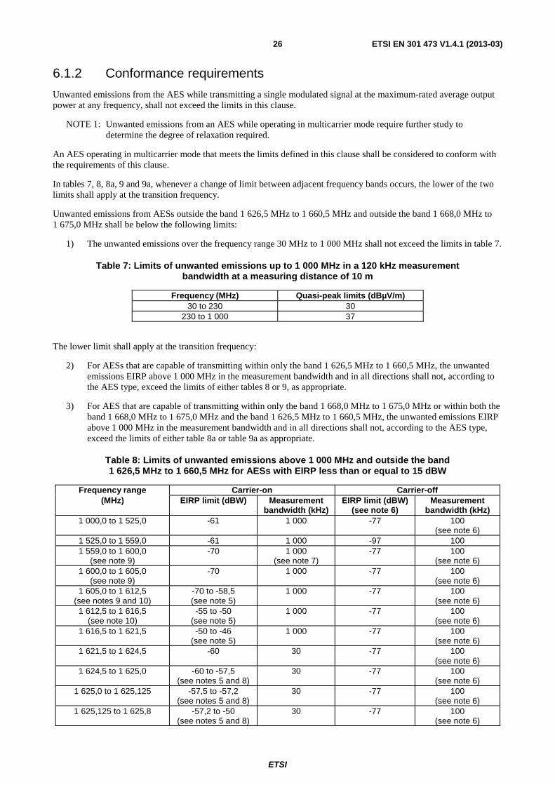
ETSI
ETSI EN 301 473 V1.4.1 (2013-03) 26
6.1.2 Conformance requirements
Unwanted emissions from the AES while transmitting a single modulated signal at the maximum-rated average output power at any frequency, shall not exceed the limits in this clause.
NOTE 1: Unwanted emissions from an AES while operating in multicarrier mode require further study to determine the degree of relaxation required.
An AES operating in multicarrier mode that meets the limits defined in this clause shall be considered to conform with the requirements of this clause.
In tables 7, 8, 8a, 9 and 9a, whenever a change of limit between adjacent frequency bands occurs, the lower of the two limits shall apply at the transition frequency.
Unwanted emissions from AESs outside the band 1 626,5 MHz to 1 660,5 MHz and outside the band 1 668,0 MHz to 1 675,0 MHz shall be below the following limits:
1) The unwanted emissions over the frequency range 30 MHz to 1 000 MHz shall not exceed the limits in table 7.
Table 7: Limits of unwanted emissions up to 1 000 MHz in a 120 kHz measurement bandwidth at a measuring distance of 10 m
Frequency (MHz) Quasi-peak limits (dBµV/m) 30 to 230 30
230 to 1 000 37
The lower limit shall apply at the transition frequency:
2) For AESs that are capable of transmitting within only the band 1 626,5 MHz to 1 660,5 MHz, the unwanted emissions EIRP above 1 000 MHz in the measurement bandwidth and in all directions shall not, according to the AES type, exceed the limits of either tables 8 or 9, as appropriate.
3) For AES that are capable of transmitting within only the band 1 668,0 MHz to 1 675,0 MHz or within both the band 1 668,0 MHz to 1 675,0 MHz and the band 1 626,5 MHz to 1 660,5 MHz, the unwanted emissions EIRP above 1 000 MHz in the measurement bandwidth and in all directions shall not, according to the AES type, exceed the limits of either table 8a or table 9a as appropriate.
Table 8: Limits of unwanted emissions above 1 000 MHz and outside the band 1 626,5 MHz to 1 660,5 MHz for AESs with EIRP less than or equal to 15 dBW
Frequency range Carrier-on Carrier-off (MHz) EIRP limit (dBW) Measurement
bandwidth (kHz) EIRP limit (dBW)
(see note 6) Measurement
bandwidth (kHz) 1 000,0 to 1 525,0 -61 1 000 -77 100
(see note 6) 1 525,0 to 1 559,0 -61 1 000 -97 100 1 559,0 to 1 600,0
(see note 9) -70 1 000
(see note 7) -77 100
(see note 6) 1 600,0 to 1 605,0
(see note 9) -70 1 000 -77 100
(see note 6) 1 605,0 to 1 612,5
(see notes 9 and 10) -70 to -58,5 (see note 5)
1 000 -77 100 (see note 6)
1 612,5 to 1 616,5 (see note 10)
-55 to -50 (see note 5)
1 000 -77 100 (see note 6)
1 616,5 to 1 621,5 -50 to -46 (see note 5)
1 000 -77 100 (see note 6)
1 621,5 to 1 624,5 -60 30 -77 100 (see note 6)
1 624,5 to 1 625,0 -60 to -57,5 (see notes 5 and 8)
30 -77 100 (see note 6)
1 625,0 to 1 625,125 -57,5 to -57,2 (see notes 5 and 8)
30 -77 100 (see note 6)
1 625,125 to 1 625,8 -57,2 to -50 (see notes 5 and 8)
30 -77 100 (see note 6)

ETSI
ETSI EN 301 473 V1.4.1 (2013-03) 27
Frequency range Carrier-on Carrier-off (MHz) EIRP limit (dBW) Measurement
bandwidth (kHz) EIRP limit (dBW)
(see note 6) Measurement
bandwidth (kHz) 1 625,8 to 1 626 -50 to -47
(see notes 5 and 8) 30 -77 100
(see note 6) 1 626 to 1 626,2 -47 to -40
(see notes 5 and 8) 30 -77 100
(see note 6) 1 626,2 to 1 626,5 -40
(see note 8) 30 -77 100
(see note 6) 1 626,5 to 1 660,5
(see note 11) NOT APPLICABLE NOT APPLICABLE NOT APPLICABLE NOT APPLICABLE
1 660,5 to 1 662,5 (see note 11)
(see note 1) (see note 1) (see note 1) (see note 1)
1 662,5 to 1 665,5 (see note 11)
-60 30 -77 100 (see note 6)
1 665,5 to 1 670,5 (see note 11)
-60 100 -77 100 (see note 6)
1 670,5 to 1 680,5 -60 300 -77 100 (see note 6)
1 680,5 to 1 690,5 -60 1 000 -77 100 (see note 6)
1 690,5 to 2 250 -60 3 000 -77 100 (see note 6)
2 250 to 12 750 -60 (see notes 2, 3 and 4)
3 000 -77 100 (see note 6)
NOTE 1: The limits for unwanted emissions in the band 1 660,5 MHz to 1 662,5 MHz shall be as defined in clause 6.2.
NOTE 2: In the band 3 253,0 MHz to 3 321,0 MHz the maximum EIRP in one, and only one, 300 kHz measurement bandwidth shall not exceed -38 dBW. Elsewhere in this band the power limit in table 8 shall be applied.
NOTE 3: In each of the bands 4 879,5 MHz to 4 981,5 MHz, 6 506,0 MHz to 6 642,0 MHz and 8 132,5 MHz to 8 302,5 MHz the maximum EIRP in one, and only one, 300 kHz measurement bandwidth shall not exceed -48 dBW. Elsewhere in this band the power limit in table 8 shall be applied.
NOTE 4: In the band 9 759,0 MHz to 9 963,0 MHz the maximum EIRP in one, and only one, 300 kHz measurement bandwidth shall not exceed -59 dBW. Elsewhere in this band the power limit in table 8 shall be applied.
NOTE 5: Linearly interpolated in dBW versus frequency. NOTE 6: In the carrier off state, peak-hold measurement techniques should be used in the bands 1 000 MHz to
1 525 MHz and 1 559 MHz to 1 626,5 MHz and from 1 662,5 MHz to 12 750 MHz. These values should be at or below the values for the carrier-on state.
NOTE 7: In the sub-band 1 573,42 MHz to 1 580,42 MHz, the average measurement time is 20 ms. NOTE 8: The power limits specified in table 8 in the 1 624,5 MHz to 1 626,5 MHz band require further study. This
study is important to determine whether less stringent limits may enhance spectrum efficiency and utilization immediately above 1 626,5 MHz.
NOTE 9: The requirements for protection of the Global Navigation Satellite Service operating in the band 1 559 MHz to 1 610 MHz are given in clause 8.
NOTE 10: There are additional requirements for the protection of the Radio Astronomy Service operating in the band 1 610,6 MHz to 1 613,8 MHz given in clause 9.
NOTE 11: There are additional requirements for the protection of the Radio Astronomy Service operating in the band 1 660 MHz to 1 670 MHz given in clause 9.

ETSI
ETSI EN 301 473 V1.4.1 (2013-03) 28
Table 8a: Limits of unwanted emissions above 1 000 MHz and outside the band 1 626,5 MHz to 1 660,5 MHz and outside the band 1 668,0 MHz to 1 675,0 MHz for AESs with EIRP less
than or equal to 15 dBW
Frequency range Carrier-on Carrier-off (MHz) EIRP limit (dBW) Measurement
bandwidth (kHz) EIRP limit (dBW)
(see note 6) Measurement
bandwidth (kHz) 1 000,0 to 1 518,0 -61 1 000 -77 100
(see note 6) 1 518,0 to 1 559,0 -61 1 000 -97 100 1 559,0 to 1 600,0
(see note 9) -70 1 000
(see note 7) -77 100
(see note 6) 1 600,0 to 1 605,0
(see note 9) -70 1 000 -77 100
(see note 6) 1 605,0 to 1 612,5
(see notes 9 and 10) -70 to -58,5 (see note 5)
1 000 -77 100 (see note 6)
1 612,5 to 1 616,5 (see note 10)
-55 to -50 (see note 5)
1 000 -77 100 (see note 6)
1 616,5 to 1 621,5 -50 to -46 (see note 5)
1 000 -77 100 (see note 6)
1 621,5 to 1 624,5 -60 30 -77 100 (see note 6)
1 624,5 to 1 625,0 -60 to -57,5 (see notes 5 and 8)
30 -77 100 (see note 6)
1 625,0 to 1 625,125 -57,5 to -57,2 (see notes 5 and 8)
30 -77 100 (see note 6)
1 625,125 to 1 625,8 -57,2 to -50 (see notes 5 and 8)
30 -77 100 (see note 6)
1 625,8 to 1 626 -50 to -47 (see notes 5 and 8)
30 -77 100 (see note 6)
1 626 to 1 626,2 -47 to -40 (see notes 5 and 8)
30 -77 100 (see note 6)
1 626,2 to 1 626,5 -40 (see note 8)
30 -77 100 (see note 6)
1 626,5 to 1 660,5 (see note 11)
NOT APPLICABLE NOT APPLICABLE NOT APPLICABLE NOT APPLICABLE
1 660,5 to 1 662,5 (see note 11)
(see note 1) (see note 1) (see note 1) (see note 1)
1 662,5 to 1 666,0 (see note 11)
-60 30 -77 100 (see note 6)
1 666,0 to 1 668,0 (see note 1) (see note 1) (see note 1) (see note 1) 1 668,0 to 1 675,0 NOT APPLICABLE NOT APPLICABLE NOT APPLICABLE NOT APPLICABLE 1 675,0 to 1 677,0 (see note 1) (see note 1) (see note 1) (see note 1) 1 677,0 to 1 680,0 -60 30 -77 100
(see note 6) 1 680,0 to 1 685,0 -60 300 -77 100
(see note 6) 1 685,0 to 1 705,0 -60 1 000 -77 100
(see note 6) 1 705,0 to 2 250 -60 3 000 -77 100
(see note 6)

ETSI
ETSI EN 301 473 V1.4.1 (2013-03) 29
Frequency range Carrier-on Carrier-off (MHz) EIRP limit (dBW) Measurement
bandwidth (kHz) EIRP limit (dBW)
(see note 6) Measurement
bandwidth (kHz) 2 250 to 12 750 -60
(see notes 2, 3 and 4) 3 000 -77 100
(see note 6) NOTE 1: The limits for unwanted emissions in the band 1 660,5 MHz to 1 662,5 MHz, the band 1 666,0 MHz to
1 668,0 MHz and the band 1 675,0 MHz to 1 677,0 MHz shall be as defined in clause 6.2. NOTE 2: In the bands 3 253,0 MHz to 3 321,0 MHz and 3 336,0 MHz to 3 350,0 MHz the maximum EIRP in one, and
only one, 3 MHz measurement bandwidth shall not exceed -38 dBW. Elsewhere in these bands the power limit in table 8a shall be applied.
NOTE 3: In the bands 4 879,5 MHz to 4 981,5 MHz and 5 004,0 MHz to 5 025,0 MHz the maximum EIRP in one, and only one, 3 MHz measurement bandwidth shall not exceed -48 dBW. Elsewhere in these bands the power limit in table 8a shall be applied.
In the bands 6 506,0 MHz to 6 642,0 MHz and 6 672,0 MHz to 6 700,0 MHz the maximum EIRP in one, and only one, 3 MHz measurement bandwidth shall not exceed -48 dBW. Elsewhere in these bands the power limit in table 8a shall be applied.
In the bands 8 132,5 MHz to 8 302,5 MHz and 8 340,0 MHz to 8 375,0 MHz the maximum EIRP in one, and only one, 3 MHz measurement bandwidth shall not exceed -48 dBW. Elsewhere in these bands the power limit in table 8a shall be applied.
NOTE 4: In the bands 9 759,0 MHz to 9 963,0 MHz and 10 008,0 MHz to 10 050,0 MHz the maximum EIRP in one, and only one, 3 MHz measurement bandwidth shall not exceed -59 dBW. Elsewhere in these bands the power limit in table 8a shall be applied.
NOTE 5: Linearly interpolated in dBW versus frequency. NOTE 6: In the carrier off state, peak-hold measurement techniques should be used in the bands 1 000 MHz to
1 518 MHz and 1 559 MHz to 1 626,5 MHz and 1 662,5MHz to 1 666,0 and from1 677,0 MHz to 12 750 MHz. These values should be at or below the values for the carrier-on state.
NOTE 7: In the sub-band 1 573,42 MHz to 1 580,42 MHz, the average measurement time is 20 ms. NOTE 8: The power limits specified in table 8 in the 1 624,5 MHz to 1 626,5 MHz band require further study. This
study is important to determine whether less stringent limits may enhance spectrum efficiency and utilization immediately above 1 626,5 MHz.
NOTE 9: The requirements for protection of the Global Navigation Satellite Service operating in the band 1 559 MHz to 1 610 MHz are given in clause 8.
NOTE 10: There are additional requirements for the protection of the Radio Astronomy Service operating in the band 1 610,6 MHz to 1 613,8 MHz given in clause 9.
NOTE 11: There are additional requirements for the protection of the Radio Astronomy Service operating in the band 1 660 MHz to 1 670 MHz given in clause 9.
Table 9: Limits of unwanted emissions above 1 000 MHz and outside the band 1 626,5 MHz to 1 660,5 MHz for AESs with an EIRP greater than 15 dBW
Frequency range Carrier-on Carrier-off (MHz) EIRP limit (dBW) Measurement
bandwidth (kHz) EIRP limit (dBW)
(see note 8) Measurement
bandwidth (kHz) 1 000,0 to 1 525,0 -61 1 000 -72 100
(see note 8) 1 525,0 to 1 559,0 -61 1 000 -103 3 1 559,0 to 1 600,0
(see note 11) -70 1 000 -77 100
(see note 8) 1 600,0 to 1 605,0
(see note 11) -70 1 000 -77 100
(see note 8) 1 605,0 to 1 610,0
(see note 11) (see note 5) 1 000 (see note 6) 1 000
(see note 8) 1 610,0 to 1 621,5
(see note 12) -46
(see note 5) 1 000 -72 100
(see note 8) 1 621,5 to 1 624,5 -46 to -40
(see note 7) 1 000 -72 100
(see note 8) 1 624,5 to 1 625,0 -60 to -57,5
(see notes 7, 9 and 10) 30 -72 100
1 625,0 to 1 625,125 -57,5 to -57,2 (see notes 7, 9 and 10)
30 -72 100
1 625,125 to 1 625,8 -57,2 to -50 (see notes 7, 9 and 10)
30 -72 100
1 625,8 to 1 626,0 -50 to -47 (see notes 7, 9 and 10)
30 -72 100
1 626,0 to 1 626,2 -47 to -40 (see notes 7, 9 and 10)
30 -72 100

ETSI
ETSI EN 301 473 V1.4.1 (2013-03) 30
Frequency range Carrier-on Carrier-off (MHz) EIRP limit (dBW) Measurement
bandwidth (kHz) EIRP limit (dBW)
(see note 8) Measurement
bandwidth (kHz) 1 626,2 to 1 626,5 -40
(see notes 9 and 10) 30 -72 100
1 626,5 to 1 660,5 (see note 13)
NOT APPLICABLE NOT APPLICABLE NOT APPLICABLE NOT APPLICABLE
1 660,5 to 1 662,5 (see note 13)
(see note 1) (see note 1) (see note 1) (see notes 1 and 8)
1 662,5 to 1 690,0 (see note 13)
-36 1 000 -72 100 (see note 8)
1 690,0 to 3 400,0 -61 (see note 2)
1 000 -72 100 (see note 8)
3 400 to 10 700 -55 (see notes 3 and 4)
1 000 -72 100 (see note 8)
10 700 to 12 750 -49 1 000 -76 100 (see note 8)
NOTE 1: The limits for unwanted emissions in the band 1 660,5 MHz to 1 662,5 MHz shall be as defined in clause 6.2. NOTE 2: In the band 3 253,0 MHz to 3 321,0 MHz the maximum EIRP in one, and only one, 300 kHz measurement
bandwidth shall not exceed -38 dBW. Elsewhere in this band the power limit in table 9 shall be applied. NOTE 3: In each of the bands 4 879,5 MHz to 4 981,5 MHz, 6 506,0 MHz to 6 642,0 MHz and 8 132,5 MHz to
8 302,5 MHz the maximum EIRP in one, and only one, 300 kHz measurement bandwidth shall not exceed -48 dBW. Elsewhere in this band the power limit in table 9 shall be applied.
NOTE 4: In the band 9 759,0 MHz to 9 963,0 MHz the maximum EIRP in one, and only one, 300 kHz measurement bandwidth shall not exceed -59 dBW. Elsewhere in this band the power limit in table 9 shall be applied.
NOTE 5: Linearly interpolated from -70 dBW/MHz at 1 605,0 MHz to -46 dBW/MHz at 1 610,0 MHz. NOTE 6: Linearly interpolated from -70 dBW/MHz at 1 605,0 MHz to -62 dBW/MHz at 1 610,0 MHz. NOTE 7: Linearly interpolated in dBW versus frequency. NOTE 8: In the carrier off state, peak-hold measurement techniques should be used in the bands 1 000 MHz to
1 525 MHz and 1 559 MHz to 1 624,5 MHz and from 1 662,5 MHz to 12 750 MHz. These values should be at or below the values for the carrier-on state.
NOTE 9: The maximum EIRP as specified in table 9 may be exceeded in the 1 624,5 MHz to 1 626,5 MHz band in a maximum of four separated 30 kHz measurement bandwidths. The upper limit for this excess power for any of these 30 kHz measurement bandwidths shall be 5 dB above the power limits defined in table 9. The total excess power from these four measurements shall not exceed 8 dB. Any two of the 30 kHz measurements bandwidths that exceed the power limits defined in table 9 shall be separated by at least one 30 kHz measurement bandwidth compliant with the power limits defined in table 9.
NOTE 10: The power limits specified in table 9 in the 1 624,5 MHz to 1 626,5 MHz band are set at the minimum level based on table 8. These limits require further study. This study is important to determine whether less stringent limits may enhance spectrum efficiency and utilization immediately above 1 626,5 MHz. This study should include the limits in note 9.
NOTE 11: The requirements for protection of the Global Navigation Satellite Service operating in the band 1 559 MHz to 1 610 MHz are given in clause 8.
NOTE 12: There are additional requirements for the protection of the Radio Astronomy Service operating in the band 1 610,6 MHz to 1 613,8 MHz given in clause 9.
NOTE 13: There are additional requirements for the protection of the Radio Astronomy Service operating in the band 1 660 MHz to 1 670 MHz given in clause 9.

ETSI
ETSI EN 301 473 V1.4.1 (2013-03) 31
Table 9a: Limits of unwanted emissions above 1 000 MHz and outside the band 1 626,5 MHz to 1 660,5 MHz and outside the band 1 668,0 MHz to 1 675,0 MHz
for AESs with an EIRP greater than 15 dBW
Frequency range Carrier-on Carrier-off (MHz) EIRP limit (dBW) Measurement
bandwidth (kHz) EIRP limit (dBW)
(see note 8) Measurement
bandwidth (kHz) 1 000,0 to 1 518,0 -61 1 000 -72 100
(see note 8) 1 518,0 to 1 559,0 -61 1 000 -103 3 1 559,0 to 1 600,0
(see note 11) -70 1 000 -77 100
(see note 8) 1 600,0 to 1 605,0
(see note 11) -70 1 000 -77 100
(see note 8) 1 605,0 to 1 610,0
(see note 11) (see note 5) 1 000 (see note 6) 1 000
(see note 8) 1 610,0 to 1 621,5
(see note 12) -46
(see note 5) 1 000 -72 100
(see note 8) 1 621,5 to 1 624,5 -46 to -40
(see note 7) 1 000 -72 100
(see note 8) 1 624,5 to 1 625,0 -60 to -57,5
(see notes 7, 9 and 10) 30 -72 100
1 625,0 to 1 625,125 -57,5 to -57,2 (see notes 7, 9 and 10)
30 -72 100
1 625,125 to 1 625,8 -57,2 to -50 (see notes 7, 9 and 10)
30 -72 100
1 625,8 to 1 626,0 -50 to -47 (see notes 7, 9 and 10)
30 -72 100
1 626,0 to 1 626,2 -47 to -40 (see notes 7, 9 and 10)
30 -72 100
1 626,2 to 1 626,5 -40 (see notes 9 and 10)
30 -72 100
1 626,5 to 1 660,5 (see note 13)
NOT APPLICABLE NOT APPLICABLE NOT APPLICABLE NOT APPLICABLE
1 660,5 to 1 662,5 (see note 13)
(see note 1) (see note 1) (see note 1) (see notes 1 and 8)
1 662,5 to 1 666,0 (see note 13)
-36 1 000 -72 100 (see note 8)
1 666,0 to 1 668,0 (see note 1) (see note 1) (see note 1) (see note 1 and 8) 1 668,0 to 1 675,0 NOT APPLICABLE NOT APPLICABLE NOT APPLICABLE NOT APPLICABLE 1 675,0 to 1 677,0 (see note 1) (see note 1) (see note 1) (see note 1 and 8) 1 677,0 to 1 704,5 -36 1 000 -72 100
(see note 8) 1 704,5 to 3 400,0 -61
(see note 2) 1 000 -72 100
(see note 8) 3 400 to 10 700 -55
(see notes 3 and 4) 1 000 -72 100
(see note 8)

ETSI
ETSI EN 301 473 V1.4.1 (2013-03) 32
Frequency range Carrier-on Carrier-off (MHz) EIRP limit (dBW) Measurement
bandwidth (kHz) EIRP limit (dBW)
(see note 8) Measurement
bandwidth (kHz) 10 700 to 12 750 -49 1 000 -76 100
(see note 8) NOTE 1: The limits for unwanted emissions in the band 1 660,5 MHz to 1 662,5 MHz, the band 1 666,0 MHz to
1 668,0 MHz and the band 1 675,0 MHz to 1 677,0 MHz shall be as defined in clause 6.2. NOTE 2: In the bands 3 253,0 MHz to 3 321,0 MHz and 3 336,0 MHz to 3 350,0 MHz the maximum EIRP in one, and
only one, 3 MHz measurement bandwidth shall not exceed -38 dBW. Elsewhere in these bands the power limit in table 9a shall be applied.
NOTE 3: In the bands 4 879,5 MHz to 4 981,5 MHz and 5 004,0 MHz to 5 025,0 MHz the maximum EIRP in one, and only one, 3 MHz measurement bandwidth shall not exceed -48 dBW. Elsewhere in these bands the power limit in table 9a shall be applied.
In the bands 6 506,0 MHz to 6 642,0 MHz and 6 672,0 MHz to 6 700,0 MHz the maximum EIRP in one, and only one, 3 MHz measurement bandwidth shall not exceed -48 dBW. Elsewhere in these bands the power limit in table 9a shall be applied.
In the bands 8 132,5 MHz to 8 302,5 MHz and 8 340,0 MHz to 8 375,0 MHz the maximum EIRP in one, and only one, 3 MHz measurement bandwidth shall not exceed -48 dBW. Elsewhere in these bands the power limit in table 9a shall be applied.
NOTE 4: In the bands 9 759,0 MHz to 9 963,0 MHz and 10 008,0 MHz to 10 050,0 MHz the maximum EIRP in one, and only one, 3 MHz measurement bandwidth shall not exceed -59 dBW. Elsewhere in these bands the power limit in table 9a shall be applied.
NOTE 5: Linearly interpolated from -70 dBW/MHz at 1 605,0 MHz to -46 dBW/MHz at 1 610,0 MHz. NOTE 6: Linearly interpolated from -70 dBW/MHz at 1 605,0 MHz to -62 dBW/MHz at 1 610,0 MHz. NOTE 7: Linearly interpolated in dBW versus frequency. NOTE 8: In the carrier off state, peak-hold measurement techniques should be used in the bands 1 000 MHz to
1 518 MHz and 1 559 MHz to 1 624,5 MHz and 1 662,5 MHz to 1 666,0 MHz and from 1 677,0 MHz to 12 750 MHz. These values should be at or below the values for the carrier-on state.
NOTE 9: The maximum EIRP as specified in table 9 may be exceeded in the 1 624,5 MHz to 1 626,5 MHz band in a maximum of four separated 30 kHz measurement bandwidths. The upper limit for this excess power for any of these 30 kHz measurement bandwidths shall be 5 dB above the power limits defined in table 9. The total excess power from these four measurements shall not exceed 8 dB. Any two of the 30 kHz measurements bandwidths that exceed the power limits defined in table 9 shall be separated by at least one 30 kHz measurement bandwidth compliant with the power limits defined in table 9.
NOTE 10: The power limits specified in table 9a in the 1 624,5 MHz to 1 626,5 MHz band are set at the minimum level based on table 8. These limits require further study. This study is important to determine whether less stringent limits may enhance spectrum efficiency and utilization immediately above 1 626,5 MHz. This study should include the limits in note 9.
NOTE 11: The requirements for protection of the Global Navigation Satellite Service operating in the band 1 559 MHz to 1 610 MHz are given in clause 8.
NOTE 12: There are additional requirements for the protection of the Radio Astronomy Service operating in the band 1 610,6 MHz to 1 613,8 MHz given in clause 9.
NOTE 13: There are additional requirements for the protection of the Radio Astronomy Service operating in the band 1 660 MHz to 1 670 MHz given in clause 9.
The conformance requirements apply for the full range of environmental conditions corresponding to the type of equipment as described in clause B.2.
NOTE 2: The power limits specified in tables 8, 8a, 9 and 9a, require further study for the extreme environmental conditions as specified in annex B to determine the degree of relaxation that is required.
6.1.3 Testing for carrier on state
6.1.3.1 Method of test
This test shall be carried out for a mid-band, the minimum and for the maximum AES transmit frequencies for which the AES is designed to operate, as specified by the applicant.
The transmit frequencies used for the test shall be entered in the test report.
The environmental test conditions are given in clause B.3.
For each test, the AES shall be set to transmit (carrier-on) on one of the specified transmit frequencies to be tested, at its maximum power for that transmit frequency, by means of the STE or by another test facility provided by the applicant.

ETSI
ETSI EN 301 473 V1.4.1 (2013-03) 33
If there is a handover function in the AES (to allow change of frequency channel during a call), this function shall be disabled.
The transmitted carrier shall be modulated by a test signal at maximum rate as specified in clause A.2.3.
In the test equipment, the spectrum analyser noise floor shall be at least 6 dB below the appropriate limits given in tables 7, 8, 8a, 9 or 9a as applicable.
The measurements are performed with the conducted method as described in annex C.
6.1.3.2 Measurement method
The spectrum analyser shall be set in sweep mode and shall be operated under the following conditions:
• frequency sweep: as required for frequency range to be assessed;
• resolution bandwidth: measurement bandwidth specified in tables 7, 8, 8a, 9 or 9a as applicable;
• video bandwidth: equal to the measurement bandwidth;
• averaging: yes;
• peak hold: no.
The measurement time shall be such that the difference of the measured levels, averaged over subsequent measurement samples, is less than 1 dB, or a measurement time of 100 ms may be used if the measured values comply with the applicable limits.
For an AES operating in a non-continuous carrier mode, the measurement shall be performed over the active part of the transmitted bursts. The total sample time used for measurement shall be not less than 40 % of the duration of the active part of the transmitted burst. The measurement shall be made over the random part of the burst, excluding any preambles or synchronization sequences.
For each of the transmit frequencies to be used for the test, measurements shall be made over the frequency range 10 kHz to 18 GHz.
6.1.3.3 Test requirements
The values of conducted unwanted emissions of the AES measured at the antenna port, plus the maximum antenna gain, as specified in clause 4.3 shall in no case exceed the limits given in tables 7, 8, 8a, 9 or 9a, as applicable.
NOTE: The maximum antenna gain is limited by RTCA DO-210D [3] which specifies that the actual maximum antenna does not exceed 17 dB.
6.1.4 Testing for carrier off state
6.1.4.1 Method of test
The AES shall be switched on and set in a non-transmitting (carrier-off) mode.
If there is a periodic automatic transmission of bursts (e.g. for location updating), the STE shall provide a means to inhibit it, or to trigger the measurement in order to analyse only the non-transmitting periods.
The environmental test conditions are given in clause B.3. In the test equipment, the spectrum analyser noise floor shall be at least 6 dB below the appropriate limits given in tables 7, 8, 8a, 9 or 9a as appropriate.
The measurements are performed with the conducted method as described in annex C.

ETSI
ETSI EN 301 473 V1.4.1 (2013-03) 34
6.1.4.2 Peak measurement method
In the case of peak measurement, the spectrum analyser shall be set in sweep mode and shall be operated under the following conditions:
• frequency sweep: as required for frequency range to be assessed;
• resolution bandwidth: measurement bandwidth specified in tables 7, 8, 8a, 9 or 9a as appropriate;
• video bandwidth: at least 3 times the measurement bandwidth;
• averaging: no;
• peak hold: yes.
The sweep time shall be the shortest possible time consistent with proper calibration and ease of operation.
The spectrum analyser shall be stepped over the frequency ranges specified in tables 7, 8, 8a, 9 or 9a as appropriate for peak measurement.
6.1.4.3 Average measurement
In the case of average measurement, the spectrum analyser shall be set in sweep mode and shall be operated under the following conditions:
• frequency sweep: as required for frequency range to be assessed;
• resolution bandwidth: measurement bandwidth specified in tables 7, 8, 8a, 9 or 9a as appropriate;
• video bandwidth: equal to the measurement bandwidth;
• averaging: yes;
• peak hold: no.
Unless otherwise stated in tables 7, 8, 8a, 9 or 9a as appropriate, the measurement time shall be such that the difference of the measured levels, averaged over subsequent measurement samples, is less than 1 dB, or a measurement time of 100 ms may be used if the measured values comply with the applicable limits.
The spectrum analyser shall be stepped over the frequency ranges specified in tables 7, 8, 8a, 9 or 9a as appropriate for average measurement.
6.1.4.4 Test requirements
The values of conducted unwanted emissions of the AES measured at the antenna port, plus the maximum antenna gain, as specified in clause 4.3 shall in no case exceed the limits given in tables 7, 8, 8a, 9 or 9a, as applicable.
NOTE: The maximum antenna gain is limited by RTCA DO-210D [3] which specifies that the actual maximum antenna does not exceed 17 dB.
ETSI
ETSI EN 301 473 V1.4.1 (2013-03) 35
6.2 Unwanted emissions limits within the band 1 626,5 MHz to 1 660,5 MHz and the band 1 660,5 MHz to 1 662,5 MHz and also within the band 1 666,0 MHz to 1 668,0 MHz, the band 1 668,0 MHz to 1 675,0 MHz and the band 1 675,0 MHz to 1 677,0 MHz
6.2.1 Purpose
The purpose is for the protection of radio services and systems operating within the frequency band 1 626,5 MHz to 1 662,5 MHz from unwanted emissions caused by AESs operating in the band 1 626,5 MHz to 1 660,5 MHz.
Protection of radio services and systems operating within the frequency band 1 666,0 MHz to 1 677,0 MHz from unwanted emissions caused by AESs operating in the band 1 668,0 MHz to 1 675,0 MHz.
6.2.2 Conformance requirements
6.2.2.1 General
Unwanted emissions from the AES while transmitting a single modulated signal at the maximum-rated average output power at any frequency, shall not exceed the limits in this clause.
NOTE: Unwanted emissions from an AES whilst operating in multicarrier mode require further study to determine the degree of relaxation required.
An AES operating in multicarrier mode that meets the limits defined in this clause shall be considered to conform with the requirements of this clause.
In tables 10, 10a and 11, whenever a change of limit between adjacent frequency bands occurs, the lower of the two limits shall apply at the transition frequency.
6.2.2.2 Specification 1: Carrier-on state
If an AES is capable of transmitting in both the band 1 626,5 MHz to 1 660,5 MHz and the band 1 668,0 MHz to 1 675,0 MHz, there are two different limits in this clause. The limits defined in tables 10 and 10a, and table 11, as appropriate, shall only apply, according to the AES type, for the current transmit band as defined below.
For an AES transmitting in the band 1 626, 5 MHz to 1 660,5 MHz:
• The maximum EIRP spectral density of the unwanted emissions from the AES in any 3 kHz band within the 1 626,5 MHz to 1 660,5 MHz band, but outside the nominated bandwidth, shall not, according to the AES type, exceed the limits in either tables 10, 10a or table 11, as appropriate. The applicant shall declare which alternative shall be used.
• The maximum EIRP spectral density of the unwanted emissions from the AES in any 3 kHz band within the 1 660,5 MHz to 1 662,5 MHz band, shall not, according to the AES type, exceed the limits in tables 10 or 11, as appropriate.
• The maximum EIRP spectral density of the unwanted emissions from the AES within the band 1 666,0 MHz to 1 677,0 MHz shall not exceed the following limits:
a) -65 dBW in any 3 kHz measurement bandwidth for AESs with EIRP less than or equal to 15 dBW.
b) -60 dBW in any 3 kHz measurement bandwidth for AESs with an EIRP greater than 15 dBW.

ETSI
ETSI EN 301 473 V1.4.1 (2013-03) 36
For an AES transmitting in the band 1 668,0 MHz to 1 675,0 MHz:
• The maximum EIRP spectral density of the unwanted emissions from the AES in any 3 kHz band within the 1 668,0 MHz to 1 675,0 MHz band, but outside the nominated bandwidth, shall not, according the AES type, exceed the limits in either tables 10, 10a or table 11, as appropriate. The applicant shall declare which alternative shall be used.
• The maximum EIRP spectral density of the unwanted emissions from the AES in any 3 kHz band within the 1 666,0 MHz to 1 668,0 MHz and the 1 675,0 MHz to 1 677,0 MHz bands, shall not, according the AES type, exceed the limits in table 10 or 11, as appropriate.
• The maximum EIRP spectral density of the unwanted emissions from the AES within the band 1 626,5 MHz to 1 662,5 MHz shall not exceed the following limits:
a) -65 dBW in any 3 kHz measurement bandwidth for AESs with EIRP less than or equal to 15 dBW.
b) -60 dBW in any 3 kHz measurement bandwidth for AESs with an EIRP greater than 15 dBW.
Table 10: Limits for unwanted emissions within the 1 626,5 MHz to 1 662,5 MHz band caused by AESs transmitting in the 1 626,5 MHz to 1 660,5 MHz band; and limits for unwanted emissions in the
1 666,0 MHz to 1 677,0 MHz band caused by AESs transmitting in the 1 668,0 MHz to 1 675,0 MHz band for AESs with an EIRP less than or equal to 15 dBW
Offset from the edge of the band of the nominated bandwidth (kHz)
Maximum EIRP (dBW) (see notes 1 and 2)
0 to 25 0 to -15 25 to 125 -15 to -50
125 to 425 -50 425 to 1 500 -50 to -65
1 500 to 36 000 -65 NOTE 1: The limits in table 10 may be exceeded provided that the sum in watts of the spectrum
components exceeding the limits of table 10 does not exceed -30 dBW. NOTE 2: There are additional requirements for the protection of the Radio Astronomy Service operating in
the band 1 660 MHz to 1 662,5 MHz and in the band 1 666,0 MHz to 1 670,0 MHz given in clause 9.

ETSI
ETSI EN 301 473 V1.4.1 (2013-03) 37
Table 10a: Limits for unwanted emissions within the 1 626,5 MHz to 1 660,5 MHz band caused by AESs transmitting in the 1 626,5 MHz to 1 660,5 MHz band; and limits for unwanted
emissions in the 1 668,0 MHz to 1 675,0 MHz band caused by AESs transmitting in the 1 668,0 MHz to 1 675,0 MHz band for AESs with an EIRP less than or equal to 15 dBW
Frequency offset (kHz)
(see notes 1, 3)
EIRP (dBW)
(see notes 2 and 5) 0 to 25 0 to -15
25 to 55 -15 to -25 (see note 4)
55 to AB -25 (see note 4)
AB to (AB + 0,35 x B3dB)
-25 to -40 (see note 4)
(AB + 0,35 x B3dB) to CD
-40
CD to (CD + 0,25 x B3dB)
-40 to -50
(CD + 0,25 x B3dB) to EF
-50
EF to 1 500 -50 to -65 1 500 to 36 000 -65
NOTE 1: Frequency offset is determined from the edge of the nominated bandwidth. NOTE 2: Linearly interpolated in dBW vs. Frequency offset. NOTE 3: The parameters AB, CD, EF are defined below. NOTE 4: The limit of -25 dBW in this table is determined on the assumption that the adjacent channel
interference results from a single interferer. This limit shall apply to AESs that are designed for operation in a network where the occurrence of two (or more) interferers, all transmitting with the maximum permitted level of unwanted emissions, does not exceed 0,1 % of the time; otherwise a limit of -30 dBW shall apply.
NOTE 5: There are additional requirements for the protection of the Radio Astronomy Service operating in the band 1 660 MHz to 1 662,5 MHz and in the band 1 666,0 MHz to 1 670,0 MHz given in clause 9.
NOTE 6: B3dB (3 dB Bandwidth) is total width of the signal spectrum 3 dB below the maximum in-band density.
The parameters AB, CD and EF are defined as a proportion of the 3dB Bandwidth as follows:
AB = (55 kHz) or (100 % of the B3dB), whichever is the greater;
CD = (95 kHz) or (200 % of the B3dB), whichever is the greater;
EF = (125 kHz) or (300 % of the B3dB), whichever is the greater.
For systems employing CDMA, the EIRP limits in tables 10, and 10a shall be decreased by 10 x log (N) dB, where N is the maximum number of AESs in the receive beam of the satellite to which these AESs are communicating and which are expected to transmit simultaneously in overlapping frequency within that same beam. This number shall be declared by the applicant.
NOTE 1: N = 1 in a TDMA system.
The conformance requirements apply for the full range of environmental conditions corresponding to the type of equipment as specified in clause B.2.
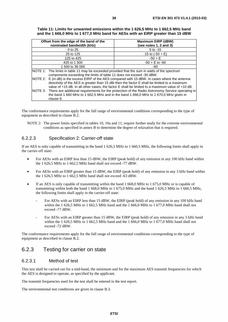
ETSI
ETSI EN 301 473 V1.4.1 (2013-03) 38
Table 11: Limits for unwanted emissions within the 1 626,5 MHz to 1 662,5 MHz band and the 1 666,0 MHz to 1 677,0 MHz band for AESs with an EIRP greater than 15 dBW
Offset from the edge of the band of the nominated bandwidth (kHz)
Maximum EIRP (dBW) (see notes 1, 2 and 3)
0 to 25 5 to -15 25 to 125 -15 to (-50 + E)
125 to 425 -50 + E 425 to 1 500 -50 + E to -60
1 500 to 36 000 -60 NOTE 1: The limits in table 11 may be exceeded provided that the sum in watts of the spectrum
components exceeding the limits of table 11 does not exceed -30 dBW. NOTE 2: E (in dB) is the excess EIRP of the AES compared with 15 dBW. In cases where the antenna
directivity of the AES is greater than 15 dBi then the factor E shall be limited to a maximum value of +15 dB. In all other cases, the factor E shall be limited to a maximum value of +10 dB.
NOTE 3: There are additional requirements for the protection of the Radio Astronomy Service operating in the band 1 660 MHz to 1 662,5 MHz and in the band 1 666,0 MHz to 1 670,0 MHz given in clause 9.
The conformance requirements apply for the full range of environmental conditions corresponding to the type of equipment as described in clause B.2.
NOTE 2: The power limits specified in tables 10, 10a and 11, require further study for the extreme environmental conditions as specified in annex B to determine the degree of relaxation that is required.
6.2.2.3 Specification 2: Carrier-off state
If an AES is only capable of transmitting in the band 1 626,5 MHz to 1 660,5 MHz, the following limits shall apply in the carrier-off state:
• For AESs with an EIRP less than 15 dBW, the EIRP (peak hold) of any emission in any 100 kHz band within the 1 626,5 MHz to 1 662,5 MHz band shall not exceed -77 dBW.
• For AESs with an EIRP greater than 15 dBW, the EIRP (peak hold) of any emission in any 3 kHz band within the 1 626,5 MHz to 1 662,5 MHz band shall not exceed -63 dBW.
• If an AES is only capable of transmitting within the band 1 668,0 MHz to 1 675,0 MHz or is capable of transmitting within both the band 1 668,0 MHz to 1 675,0 MHz and the band 1 626,5 MHz to 1 660,5 MHz, the following limits shall apply in the carrier-off state:
- For AESs with an EIRP less than 15 dBW, the EIRP (peak hold) of any emission in any 100 kHz band within the 1 626,5 MHz to 1 662,5 MHz band and the 1 666,0 MHz to 1 677,0 MHz band shall not exceed -77 dBW.
- For AESs with an EIRP greater than 15 dBW, the EIRP (peak hold) of any emission in any 3 kHz band within the 1 626,5 MHz to 1 662,5 MHz band and the 1 666,0 MHz to 1 677,0 MHz band shall not exceed -72 dBW.
The conformance requirements apply for the full range of environmental conditions corresponding to the type of equipment as described in clause B.2.
6.2.3 Testing for carrier on state
6.2.3.1 Method of test
This test shall be carried out for a mid-band, the minimum and for the maximum AES transmit frequencies for which the AES is designed to operate, as specified by the applicant.
The transmit frequencies used for the test shall be entered in the test report.
The environmental test conditions are given in clause B.3.

ETSI
ETSI EN 301 473 V1.4.1 (2013-03) 39
For each test, the AES shall be set to transmit (carrier-on) on one of the specified transmit frequencies to be tested, at its maximum power for that transmit frequency, by means of the STE or by another test facility provided by the applicant.
If there is a handover function in the AES (to allow change of frequency channel during a call), this function shall be disabled.
The transmitted carrier shall be modulated by a test signal at maximum rate as specified in clause A.2.3.
In the test equipment, the spectrum analyser noise floor shall be at least 6 dB below the appropriate limits given in tables 10, 10a or 11 as applicable.
The measurements are performed with the conducted method as described in annex C.
6.2.3.2 Measurement method
The spectrum analyser shall be set in sweep mode and shall be operated under the following conditions:
• frequency sweep: as required for frequency range to be assessed;
• resolution bandwidth: measurement bandwidth specified in tables 10, 10a or 11 as applicable;
• video bandwidth: equal to the measurement bandwidth;
• averaging: yes;
• peak hold: no.
The measurement time shall be such that the difference of the measured levels, averaged over subsequent measurement samples, is less than 1 dB, or a measurement time of 100 ms may be used if the measured values comply with the applicable limits.
For a AES operating in a non-continuous carrier mode, the measurement shall be performed over the active part of the transmitted bursts. The total sample time used for measurement shall be not less than 40 % of the duration of the active part of the transmitted burst. The measurement shall be made over the random part of the burst, excluding any preambles or synchronization sequences.
For each of the transmit frequencies to be used for the test, measurements shall be made over the frequency ranges specified in tables 10, 10a or 11 as appropriate.
6.2.3.3 Test requirements
The values of conducted unwanted emissions of the AES measured at the antenna port, plus the maximum antenna gain, as specified in clause 4.3 shall in no case exceed the limits given in tables 10, 10a or 11, as applicable.
NOTE: The maximum antenna gain is limited by RTCA DO-210D [3] which specifies that the actual maximum antenna does not exceed 17 dB.
6.2.4 Testing for carrier off state
6.2.4.1 Method of test
The AES shall be switched on and set in a non-transmitting (carrier-off) mode.
If there is a periodic automatic transmission of bursts (e.g. for location updating), the STE shall provide a means to inhibit it, or to trigger the measurement in order to analyse only the non-transmitting periods.
The environmental test conditions are given in clause B.3. In the test equipment, the spectrum analyser noise floor shall be at least 6 dB below the appropriate limits given in tables 10, 10a or 11 as appropriate.
The measurements are performed with the conducted method as described in annex C.

ETSI
ETSI EN 301 473 V1.4.1 (2013-03) 40
6.2.4.2 Peak measurement method
In the case of peak measurement, the spectrum analyser shall be set in sweep mode and shall be operated under the following conditions:
• frequency sweep: as required for frequency range to be assessed;
• resolution bandwidth: measurement bandwidth specified in tables 10, 10a or 11 as appropriate;
• video bandwidth: at least 3 times the measurement bandwidth;
• averaging: no;
• peak hold: yes.
The sweep time shall be the shortest possible time consistent with proper calibration and ease of operation.
The spectrum analyser shall be stepped over the frequency ranges specified in tables 10, 10a or 11 as appropriate for peak measurement.
6.2.4.3 Average measurement
In the case of average measurement, the spectrum analyser shall be set in sweep mode and shall be operated under the following conditions:
• frequency sweep: as required for frequency range to be assessed;
• resolution bandwidth: measurement bandwidth specified in tables 10, 10a or 11 as appropriate;
• video bandwidth: equal to the measurement bandwidth;
• averaging: yes;
• peak hold: no.
Unless otherwise stated in tables 10, 10a or 11 as appropriate, the measurement time shall be such that the difference of the measured levels, averaged over subsequent measurement samples, is less than 1 dB, or a measurement time of 100 ms may be used if the measured values comply with the applicable limits.
The spectrum analyser shall be stepped over the frequency ranges specified in tables 10, 10a or 11 as appropriate for average measurement.
6.2.4.4 Test requirements
The values of conducted unwanted emissions of the AES measured at the antenna port, plus the maximum antenna gain, as specified in clause 4.3 shall in no case exceed the limits given in tables 10, 10a or 11, as applicable.
NOTE: The maximum antenna gain is limited by RTCA DO-210D [3] which specifies that the actual maximum antenna does not exceed 17 dB.
6.3 AES Control and Monitoring Functions (CMF)
6.3.1 Special test equipment
Many of the tests in this clause require that the AES be situated in an environment where receipt of a network control channel and of NCF commands is controlled by the test laboratory. This will require the provision of Special Test Equipment (see clause A.2). This STE shall provide the means to generate and to communicate to the AES, either radiated via its antenna or conducted via direct connection to its antenna port, the network control channel and the required NCF commands, under the control of the test laboratory. The STE shall also provide means for the test laboratory to interface its test equipment with the AES for the purpose of monitoring the AES responses.

ETSI
ETSI EN 301 473 V1.4.1 (2013-03) 41
6.3.2 Self-monitoring functions
6.3.2.1 Processor monitoring
6.3.2.1.1 Purpose
The purpose is for the protection of radio services and systems from uncontrolled RF transmissions from the AES.
6.3.2.1.2 Conformance requirements
The AES shall incorporate a processor monitoring function for each of its processors involved in the manipulation of traffic and in control and monitoring functions.
The processor monitoring function shall detect failure of the processor hardware and software.
Not later than 1 s after any detectable fault condition occurs, the transmissions shall be suppressed (carrier-off) until the processor monitoring function has determined that all fault conditions have been cleared.
The fault conditions which cause transmission shutdown shall be specified and declared by the applicant.
The conformance requirements apply for the environmental conditions as specified in clause B.2.
6.3.2.1.3 Method of test
As it is considered impracticable to artificially induce processor faults in an AES, no test is given for the processor monitoring function.
6.3.2.2 Transmit frequency generation sub-system monitoring
6.3.2.2.1 Purpose
The purpose is for the protection of radio services and systems from uncontrolled RF transmissions from the AES.
6.3.2.2.2 Conformance requirements
The AES shall incorporate a transmit frequency generation sub-system monitoring function.
Not later than 5 s after any detectable failure of the transmit frequency generation sub-system occurs, the transmissions shall be suppressed (carrier-off) until the transmit frequency generation sub-system monitoring function has determined that all fault conditions have been cleared.
The fault conditions which cause transmission shutdown shall be specified and declared by the applicant.
The conformance requirements apply for the environmental conditions as specified in clause B.2.
6.3.2.2.3 Method of test
As it is considered impracticable to artificially induce transmit frequency generation sub-system faults in an AES, no test is given for the transmit frequency generation sub-system monitoring function.
6.3.3 Network control authorization and reception
6.3.3.1 Network control authorization
6.3.3.1.1 Purpose
The purpose is for the protection of radio services and systems from uncontrolled RF transmissions from the AES.
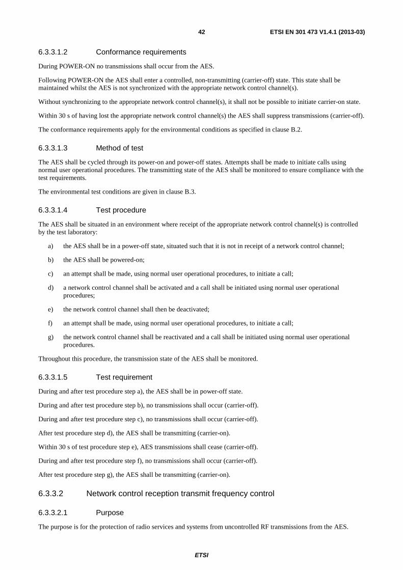
ETSI
ETSI EN 301 473 V1.4.1 (2013-03) 42
6.3.3.1.2 Conformance requirements
During POWER-ON no transmissions shall occur from the AES.
Following POWER-ON the AES shall enter a controlled, non-transmitting (carrier-off) state. This state shall be maintained whilst the AES is not synchronized with the appropriate network control channel(s).
Without synchronizing to the appropriate network control channel(s), it shall not be possible to initiate carrier-on state.
Within 30 s of having lost the appropriate network control channel(s) the AES shall suppress transmissions (carrier-off).
The conformance requirements apply for the environmental conditions as specified in clause B.2.
6.3.3.1.3 Method of test
The AES shall be cycled through its power-on and power-off states. Attempts shall be made to initiate calls using normal user operational procedures. The transmitting state of the AES shall be monitored to ensure compliance with the test requirements.
The environmental test conditions are given in clause B.3.
6.3.3.1.4 Test procedure
The AES shall be situated in an environment where receipt of the appropriate network control channel(s) is controlled by the test laboratory:
a) the AES shall be in a power-off state, situated such that it is not in receipt of a network control channel;
b) the AES shall be powered-on;
c) an attempt shall be made, using normal user operational procedures, to initiate a call;
d) a network control channel shall be activated and a call shall be initiated using normal user operational procedures;
e) the network control channel shall then be deactivated;
f) an attempt shall be made, using normal user operational procedures, to initiate a call;
g) the network control channel shall be reactivated and a call shall be initiated using normal user operational procedures.
Throughout this procedure, the transmission state of the AES shall be monitored.
6.3.3.1.5 Test requirement
During and after test procedure step a), the AES shall be in power-off state.
During and after test procedure step b), no transmissions shall occur (carrier-off).
During and after test procedure step c), no transmissions shall occur (carrier-off).
After test procedure step d), the AES shall be transmitting (carrier-on).
Within 30 s of test procedure step e), AES transmissions shall cease (carrier-off).
During and after test procedure step f), no transmissions shall occur (carrier-off).
After test procedure step g), the AES shall be transmitting (carrier-on).
6.3.3.2 Network control reception transmit frequency control
6.3.3.2.1 Purpose
The purpose is for the protection of radio services and systems from uncontrolled RF transmissions from the AES.

ETSI
ETSI EN 301 473 V1.4.1 (2013-03) 43
6.3.3.2.2 Conformance requirements
The AES shall set the carrier frequency of its transmission according to the command of the NCF. The carrier frequency has to be controlled such, that the entire nominated bandwidth of the terminal falls completely within the operational frequency band(s) specified and declared by the applicant.
The conformance requirements apply for the environmental conditions as specified in clause B.2.
6.3.3.2.3 Method of test
The nominated bandwidth of the AES shall be monitored relative to the carrier frequency commanded, and relative to the operational frequency bands for the AES specified by the applicant.
The environmental test conditions are given in clause B.3.
6.3.3.2.4 Test procedure
This test shall be carried out at least twice, once for the minimum and once for the maximum AES transmit frequency for which the AES is designed to operate, as specified by the applicant.
Where available, two additional transmit frequencies shall also be tested. These frequencies shall be equally spaced between the minimum and maximum frequencies. The commanded transmit frequencies used for the test shall be entered in the test report.
The AES shall be situated in an environment where receipt of a network control channel and of NCF commands is controlled by the test laboratory:
a) a network control channel shall be activated and the AES powered-on;
b) an appropriate NCF control message shall be sent, commanding the AES to set its carrier frequency to one of the transmit frequencies to be tested;
c) the test shall be repeated for the other transmit frequencies to be tested.
The carrier mask for the transmit frequency under test shall be monitored on a spectrum analyser, using the procedures given in clauses 6.1.3 and 6.1.4.
6.3.3.2.5 Test requirement
The AES shall set the centre frequency of its transmission according to the NCF command.
The entire nominated bandwidth for each transmit frequency tested shall be contained completely within the operational frequency band(s) specified by the applicant.
6.4 Equipment identity
6.4.1 Purpose
The purpose is for the protection of radio services and systems from uncontrolled RF transmissions from the AES.
6.4.2 Conformance requirements
Each AES shall have a unique AES Identification Code (MIC) within its network.
It shall not be possible for the user to alter the MIC using any normally accessible procedure.
The AES shall be capable of transmitting its identification code upon reception of an appropriate NCF command addressed to it.
The conformance requirements apply for the environmental conditions as specified in clause B.2.

ETSI
ETSI EN 301 473 V1.4.1 (2013-03) 44
6.4.3 Method of test
It is impracticable to test that each AES has a unique MES identification code (MIC) within its network, and that it is not possible for the user to alter the MIC using any normally accessible procedure. Consequently, no tests are given for these requirements.
The transmissions of the AES in response to an NCF command to send its identification code shall be monitored and the identification code received shall be verified.
The environmental test conditions are given in clause B.3.
6.4.4 Test procedure
The AES shall be situated in an environment where receipt of a network control channel and of NCF commands is controlled by the test laboratory:
a) a network control channel shall be activated and the AES powered-on;
b) an appropriate NCF control message shall be sent, commanding the AES to transmit its identification code;
c) the message sent by the AES shall be analysed.
6.4.5 Test requirements
The MES identification code in the message sent in step c) shall be verified against that supplied by the applicant for the AES.
7 Requirements for NGSO AES transmitting in the band 1 980 MHz to 2 010 MHz
This clause shall only apply for NGSO AESs.
7.1 Unwanted emissions limits outside the band 1 980,1 MHz to 2 009,9 MHz (carrier-on)
7.1.1 Purpose
The purpose is for the protection of other radio services operating outside the band 1 980 MHz to 2 010 MHz from emissions caused by AESs operating within the band 1 980,1 MHz to 2 009,9 MHz.
7.1.2 Conformance requirements
The maximum EIRP density of the unwanted emissions from the AES outside the band 1 980,1 MHz to 2 009,9 MHz shall not exceed the limits in table 12.
In table 12, whenever a change of limit between adjacent frequency bands occurs, the lower of the two limits shall apply at the transition frequency.

ETSI
ETSI EN 301 473 V1.4.1 (2013-03) 45
Table 12: Unwanted emissions outside the band 1 980,1 MHz to 2 009,9 MHz
Frequency Carrier-on (MHz) EIRP
(dBW) Measurement
bandwidth Measurement method
0,01 to 30 -66 10 kHz Peak hold 30 to 1 000 -66 100 kHz Peak hold
1 000 to 1 559 -60 3 MHz Average 1 559 to 1 605 (see note 1) 1 605 to 1 610 (see note 1)
-82,2 1 MHz Average (see note 2)
1 610 to 1 626,5 (see note 3)
-70 1 MHz Average
1 626,5 to 1 950 (see note 4)
-60 3 MHz Average
1 950 to 1 960 -60 1 MHz Average 1 960 to 1 970 -60 300 kHz Average 1 970 to 1 975 -60 100 kHz Average
1 975 to 1 978,1 -60 30 kHz Average 1 978,1 to 1 980,1 The levels in table 11 for the frequency offset 0 MHz to 2 MHz shall apply from
1 980,1 MHz to 1 978,1 MHz 1 980,1 to 2 009,9 Not applicable Not applicable Not applicable 2 009,9 to 2 011,9 The levels in table 11 for the frequency offset 0 MHz to 2 MHz shall apply from
2 009,9 MHz to 2 011,9 MHz 2 011,9 to 2 015 -60 30 kHz Average 2 015 to 2 020 -60 100 kHz Average 2 020 to 2 030 -60 300 kHz Average 2 030 to 2 040 -60 1 MHz Average 2 040 to 2 600 -60 3 MHz Average
2 600 to 18 000 -60 3 MHz Peak hold NOTE 1: The requirements for protection of the Global Navigation Satellite Service operating in the band
1 559 MHz to 1 610 MHz are given in clause 8. NOTE 2: In these sub-bands the average measurement time is 20 ms. NOTE 3: There are additional requirements for the protection of the Radio Astronomy Service operating in the
band 1 610,6 MHz to 1 613,8 MHz given in clause 9. NOTE 4: There are additional requirements for the protection of the Radio Astronomy Service operating in the
band 1 660 MHz to 1 670 MHz given in clause 9.
The conformance requirements apply for the full range of environmental conditions corresponding to the type of equipment as specified in clause B.2.
7.1.3 Method of test
This test shall be carried out for the minimum and for the maximum AES transmit frequencies for which the AES is designed to operate, as specified by the applicant.
The environmental test conditions are given in clause B.3.
For each test, the AES shall be set to transmit (carrier-on) on one of the specified transmitting frequencies to be tested at its maximum power for that transmit frequency, by means of the STE or by another test facility provided by the applicant.
If there is a handover function in the AES (to allow change of frequency channel during a call), this function shall be disabled.
The transmitted carrier shall be modulated by a test signal at maximum rate as specified in clause A.2.3.
In the test equipment, the spectrum analyser noise floor shall be at least 6 dB below the appropriate limits given in table 12.
The measurements are performed with the conducted method as described in annex C.

ETSI
ETSI EN 301 473 V1.4.1 (2013-03) 46
7.1.4 Peak measurement
In the case of peak measurement, the spectrum analyser shall be set in sweep mode and shall be operated under the following conditions:
• frequency sweep: as required for frequency range to be assessed;
• resolution bandwidth: measurement bandwidth specified in table 12;
• video bandwidth: at least 3 times the measurement bandwidth;
• averaging: no;
• peak hold: yes.
The sweep time shall be the shortest possible time consistent with proper calibration and ease of operation.
The spectrum analyser shall be stepped over the frequency ranges specified in table 12 for peak measurement.
7.1.5 Average measurement
In the case of average measurement, the spectrum analyser shall be set in sweep mode and shall be operated under the following conditions:
• frequency sweep: as required for frequency range to be assessed;
• resolution bandwidth: measurement bandwidth specified in table 12;
• video bandwidth: equal to the measurement bandwidth;
• averaging: yes;
• peak hold: no.
Unless otherwise stated in table 12, the measurement time shall be such that the difference of the measured levels, averaged over subsequent measurement samples, is less than 1 dB, or a measurement time of 100 ms may be used if the measured values comply with the applicable limits.
For a AES operating in a non-continuous carrier mode, the measurement shall be performed over the active part of the transmitted bursts. The total sample time used for measurement shall be not less than 40 % of the duration of the active part of the transmitted burst. The measurement shall be made over the random part of the burst, excluding any preambles or synchronization sequences.
The spectrum analyser shall be stepped over the frequency ranges specified in table 12 for average measurement.
7.1.6 Test requirements
The values of conducted unwanted emissions of the AES measured at the antenna port, plus the maximum antenna gain, as specified in clause 4.3 shall in no case exceed the limits given in table 12.
7.2 Unwanted emissions limits within the bands 1 980,1 MHz to 2 009,9 MHz, 1 978,1 MHz to 1 980,1 MHz and 2 009,9 MHz to 2 011,9 MHz (carrier-on)
7.2.1 Purpose
The purpose is for the protection of radio services and systems operating within the frequency band 1 978,1 MHz to 2 011,9 MHz from unwanted emissions caused by AESs operating in the band 1 980,1 MHz to 2 009,9 MHz.
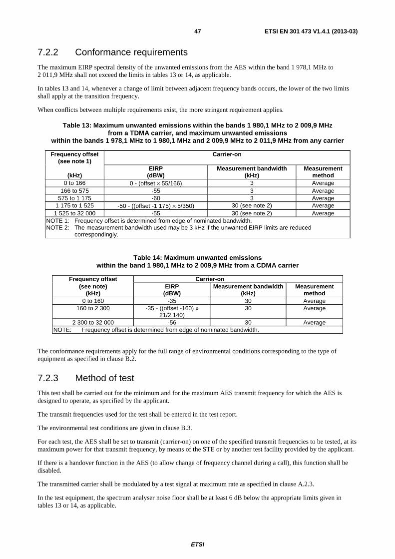
ETSI
ETSI EN 301 473 V1.4.1 (2013-03) 47
7.2.2 Conformance requirements
The maximum EIRP spectral density of the unwanted emissions from the AES within the band 1 978,1 MHz to 2 011,9 MHz shall not exceed the limits in tables 13 or 14, as applicable.
In tables 13 and 14, whenever a change of limit between adjacent frequency bands occurs, the lower of the two limits shall apply at the transition frequency.
When conflicts between multiple requirements exist, the more stringent requirement applies.
Table 13: Maximum unwanted emissions within the bands 1 980,1 MHz to 2 009,9 MHz from a TDMA carrier, and maximum unwanted emissions
within the bands 1 978,1 MHz to 1 980,1 MHz and 2 009,9 MHz to 2 011,9 MHz from any carrier
Frequency offset (see note 1)
Carrier-on
(kHz)
EIRP (dBW)
Measurement bandwidth (kHz)
Measurement method
0 to 166 0 - (offset × 55/166) 3 Average 166 to 575 -55 3 Average
575 to 1 175 -60 3 Average 1 175 to 1 525 -50 - ((offset -1 175) × 5/350) 30 (see note 2) Average 1 525 to 32 000 -55 30 (see note 2) Average
NOTE 1: Frequency offset is determined from edge of nominated bandwidth. NOTE 2: The measurement bandwidth used may be 3 kHz if the unwanted EIRP limits are reduced
correspondingly.
Table 14: Maximum unwanted emissions within the band 1 980,1 MHz to 2 009,9 MHz from a CDMA carrier
Frequency offset Carrier-on (see note)
(kHz) EIRP
(dBW) Measurement bandwidth
(kHz) Measurement
method 0 to 160 -35 30 Average
160 to 2 300 -35 - ((offset -160) x 21/2 140)
30 Average
2 300 to 32 000 -56 30 Average NOTE: Frequency offset is determined from edge of nominated bandwidth.
The conformance requirements apply for the full range of environmental conditions corresponding to the type of equipment as specified in clause B.2.
7.2.3 Method of test
This test shall be carried out for the minimum and for the maximum AES transmit frequency for which the AES is designed to operate, as specified by the applicant.
The transmit frequencies used for the test shall be entered in the test report.
The environmental test conditions are given in clause B.3.
For each test, the AES shall be set to transmit (carrier-on) on one of the specified transmit frequencies to be tested, at its maximum power for that transmit frequency, by means of the STE or by another test facility provided by the applicant.
If there is a handover function in the AES (to allow change of frequency channel during a call), this function shall be disabled.
The transmitted carrier shall be modulated by a test signal at maximum rate as specified in clause A.2.3.
In the test equipment, the spectrum analyser noise floor shall be at least 6 dB below the appropriate limits given in tables 13 or 14, as applicable.

ETSI
ETSI EN 301 473 V1.4.1 (2013-03) 48
The measurements are performed with the conducted method as described in annex C.
7.2.4 Measurement method
The spectrum analyser shall be set in sweep mode and shall be operated under the following conditions:
• frequency sweep: as required for frequency range to be assessed;
• resolution bandwidth: measurement bandwidth specified in table 13 or 14, as applicable;
• video bandwidth: equal to the measurement bandwidth;
• averaging: yes;
• peak hold: no.
The measurement time should be such that the difference of the measured levels, averaged over subsequent measurement samples, is less than 1 dB, or a measurement time of 100 ms may be used if the measured values comply with the applicable limits.
For a AES operating in a non-continuous carrier mode, the measurement shall be performed over the active part of the transmitted bursts. The total sample time used for measurement shall be not less than 40 % of the duration of the active part of the transmitted burst. The measurement shall be made over the random part of the burst, excluding any preambles or synchronization sequences.
For each of the transmit frequencies to be used for the test, measurements shall be made over the frequency ranges from 1 978,1 MHz to fc - a and from fc + b to 2 011,9 MHz, fc - a being the lower boundary frequency of the nominated
bandwidth for the transmit frequency being tested, and fc + b being the upper boundary frequency of the nominated
bandwidth for the transmit frequency being tested.
7.2.5 Test requirements
For measurements of conducted unwanted emissions, the measured values plus the maximum antenna gain as specified in clause 4.3, shall in no case exceed the limits given in table 13 or table 14, as applicable, over the frequency range 1 978,1 MHz to 2 011,9 MHz.
7.3 Unwanted emissions limits (carrier-off)
7.3.1 Purpose
The purpose is for the protection of other radio services and systems from unwanted emissions caused by AESs in the carrier-off state.
7.3.2 Conformance requirements
The maximum EIRP of the unwanted emissions from the AESs in the carrier-off state shall not exceed the limits in table 15. In no circumstances shall the unwanted emissions from an AES in its carrier-off state exceed the unwanted emissions from the AES when in its carrier-on state.
In table 15, whenever a change of limit between adjacent frequency bands occurs, the lower of the two limits shall apply at the transition frequency.

ETSI
ETSI EN 301 473 V1.4.1 (2013-03) 49
Table 15: Maximum EIRP of the unwanted emissions in the carrier-off state
Frequency (MHz)
EIRP (dBW)
Measurement bandwidth (kHz)
Measurement method
0,01 to 30 -87 10 peak hold 30 to 1 000 -87 100 peak hold
1 000 to 1 559 -77 100 peak hold 1 559 to 1 605 (see note 1) 1 605 to 1 610 (see note 1)
-77 100 peak hold
1 610 to 18 000 (see note 2)
-77 100 peak hold
NOTE 1: The requirements for protection of the Global Navigation Satellite Service operating in the band 1 559 MHz to 1 610 MHz are given in clause 8.
NOTE 2: There are additional requirements for the protection of the Radio Astronomy Services operating in the band 1 610,6 MHz to 1 613,8 MHz and in the band 1 660 MHz to 1 670 MHz given in clause 9.
The conformance requirements apply for the full range of environmental conditions corresponding to the type of equipment as specified in clause B.2.
7.3.3 Method of test
The AES shall be switched on and set in a non-transmitting (carrier-off) mode.
If there is a periodic automatic transmission of bursts (e.g. for location updating), the STE shall provide a means to inhibit it, or to trigger the measurement in order to analyse only the non-transmitting periods.
The environmental test conditions are given in clause B.3.
In the test equipment, the spectrum analyser noise floor shall be at least 6 dB below the appropriate limits given in table 15.
The measurements are performed with the conducted method as described in annex C.
7.3.4 Peak measurement
In the case of peak measurement, the spectrum analyser shall be set in sweep mode and shall be operated under the following conditions:
• frequency sweep: as required for frequency range to be assessed;
• resolution bandwidth: measurement bandwidth specified in table 15;
• video bandwidth: at least 3 times the measurement bandwidth;
• averaging: no;
• peak hold: yes.
The sweep time shall be the shortest possible time consistent with proper calibration and ease of operation.
The spectrum analyser shall be stepped over the frequency ranges specified.
7.3.5 Average measurement
In the case of average measurement, the spectrum analyser shall be set in sweep mode and shall be operated under the following conditions:
• frequency sweep: as required for frequency range to be assessed;
• resolution bandwidth: measurement bandwidth specified in table 15;

ETSI
ETSI EN 301 473 V1.4.1 (2013-03) 50
• video bandwidth: equal to the measurement bandwidth;
• averaging: yes;
• peak hold: no.
The measurement time shall be 20 ms.
The spectrum analyser shall be stepped over the frequency ranges specified in table 15 for average measurement.
7.3.6 Test requirements
For measurements of conducted unwanted emissions of the AES, the measured values plus the maximum antenna gain as specified in clause 4.3 shall in no case exceed the limits given in table 15.
7.4 AES Control and Monitoring Functions (CMF)
7.4.1 Special test equipment
Many of the tests in this clause require that the AES be situated in an environment where receipt of a network control channel and of NCF commands is controlled by the test laboratory. This will require the provision of Special Test Equipment (see clause A.2). This STE shall provide the means to generate and to communicate to the AES, either radiated via its antenna or conducted via direct connection to its antenna port, the network control channel and the required NCF commands, under the control of the test laboratory. The STE shall also provide means for the test laboratory to interface its test equipment with the AES for the purpose of monitoring the AES responses.
7.4.2 Self-monitoring functions
7.4.2.1 Processor monitoring
7.4.2.1.1 Purpose
The purpose is for the protection of radio services and systems from uncontrolled RF transmissions from the AES.
7.4.2.1.2 Conformance requirements
The AES shall incorporate a processor monitoring function for each of its processors involved in the manipulation of traffic and in control and monitoring functions.
The processor monitoring function shall detect failure of the processor hardware and software.
Not later than 1 s after any detectable fault condition occurs, the transmissions shall be suppressed (carrier-off) until the processor monitoring function has determined that all fault conditions have been cleared.
The fault conditions which cause transmission shutdown shall be specified and declared by the applicant.
The conformance requirements apply for the environmental conditions as specified in clause B.2.
7.4.2.1.3 Method of test
As it is considered impracticable to artificially induce processor faults in an AES, no test is given for the processor monitoring function.
7.4.2.2 Transmit frequency generation sub-system monitoring
7.4.2.2.1 Purpose
The purpose is for the protection of radio services and systems from uncontrolled RF transmissions from the AES.
ETSI
ETSI EN 301 473 V1.4.1 (2013-03) 51
7.4.2.2.2 Conformance requirements
The AES shall incorporate a transmit frequency generation sub-system monitoring function.
Not later than 5 s after any detectable failure of the transmit frequency generation sub-system occurs, the transmissions shall be suppressed (carrier-off) until the transmit frequency generation sub-system monitoring function has determined that all fault conditions have been cleared.
The fault conditions which cause transmission shutdown shall be specified and declared by the applicant.
The conformance requirements apply for the environmental conditions as specified in clause B.2.
7.4.2.2.3 Method of test
As it is considered impracticable to artificially induce transmit frequency generation sub-system faults in an AES, no test is given for the transmit frequency generation sub-system monitoring function.
7.4.3 Network control authorization and reception
7.4.3.1 Network control authorization
7.4.3.1.1 Purpose
The purpose is for the protection of radio services and systems from uncontrolled RF transmissions from the AES.
7.4.3.1.2 Conformance requirements
During POWER-ON no transmissions shall occur from the AES.
Following POWER-ON the AES shall enter a controlled, non-transmitting (carrier-off) state. This state shall be maintained whilst the AES is not synchronized with the appropriate network control channel(s).
Without synchronizing to the appropriate network control channel(s), it shall not be possible to initiate carrier-on state.
Within 30 s of having lost the appropriate network control channel(s) the AES shall suppress transmissions (carrier-off).
The conformance requirements apply for the environmental conditions as specified in clause B.2.
7.4.3.1.3 Method of test
The AES shall be cycled through its power-on and power-off states. Attempts shall be made to initiate calls using normal user operational procedures. The transmitting state of the AES shall be monitored to ensure compliance with the test requirements.
The environmental test conditions are given in clause B.3.
7.4.3.1.4 Test procedure
The AES shall be situated in an environment where receipt of the appropriate network control channel(s) is controlled by the test laboratory:
a) the AES shall be in a power-off state, situated such that it is not in receipt of a network control channel;
b) the AES shall be powered-on;
c) an attempt shall be made, using normal user operational procedures, to initiate a call;
d) a network control channel shall be activated and a call shall be initiated using normal user operational procedures;
e) the network control channel shall then be deactivated;
f) an attempt shall be made, using normal user operational procedures, to initiate a call;

ETSI
ETSI EN 301 473 V1.4.1 (2013-03) 52
g) the network control channel shall be reactivated and a call shall be initiated using normal user operational procedures.
Throughout this procedure, the transmission state of the AES shall be monitored.
7.4.3.1.5 Test requirement
During and after test procedure step a), the AES shall be in power-off state.
During and after test procedure step b), no transmissions shall occur (carrier-off).
During and after test procedure step c), no transmissions shall occur (carrier-off).
After test procedure step d), the AES shall be transmitting (carrier-on).
Within 30 s of test procedure step e), AES transmissions shall cease (carrier-off).
During and after test procedure step f), no transmissions shall occur (carrier-off).
After test procedure step g), the AES shall be transmitting (carrier-on).
7.4.3.2 Network control reception
7.4.3.2.1 Transmit frequency control
7.4.3.2.1.1 Purpose
The purpose is for the protection of radio services and systems from uncontrolled RF transmissions from the AES.
7.4.3.2.1.2 Conformance requirements
The AES shall set the carrier frequency of its transmission according to the command of the NCF. The carrier frequency has to be controlled such, that the entire nominated bandwidth of the terminal falls completely within the operational frequency band(s) specified and declared by the applicant.
The conformance requirements apply for the environmental conditions as specified in clause B.2.
7.4.3.2.1.3 Method of test
The nominated bandwidth of the AES shall be monitored relative to the carrier frequency commanded, and relative to the operational frequency bands for the AES specified by the applicant.
The environmental test conditions are given in clause B.3.
7.4.3.2.1.4 Test procedure
This test shall be carried out at least twice, once for the minimum and once for the maximum AES transmit frequency for which the AES is designed to operate, as specified by the applicant.
Where available, two additional transmit frequencies shall also be tested. These frequencies shall be equally spaced between the minimum and maximum frequencies. The commanded transmit frequencies used for the test shall be entered in the test report.
The AES shall be situated in an environment where receipt of a network control channel and of NCF commands is controlled by the test laboratory.
a) A network control channel shall be activated and the AES powered-on.
b) An appropriate NCF control message shall be sent, commanding the AES to set its carrier frequency to one of the transmit frequencies to be tested.
c) The test shall be repeated for the other transmit frequencies to be tested.
ETSI
ETSI EN 301 473 V1.4.1 (2013-03) 53
The carrier mask for the transmit frequency under test shall be monitored on a spectrum analyser, using the procedures given in clauses 7.2.3 and 7.2.4.
7.4.3.2.1.5 Test requirement
The AES shall set the centre frequency of its transmission according to the NCF command.
The entire nominated bandwidth for each transmit frequency tested shall be contained completely within the operational frequency band(s) specified by the applicant.
7.5 Equipment identity
7.5.1 Purpose
The purpose is for the protection of radio services and systems from uncontrolled RF transmissions from the AES.
7.5.2 Conformance requirements
Each AES shall have a unique AES Identification Code (MIC) within its network.
It shall not be possible for the user to alter the MIC using any normally accessible procedure.
The AES shall be capable of transmitting its identification code upon reception of an appropriate NCF command addressed to it.
The conformance requirements apply for the environmental conditions as specified in clause B.2.
7.5.3 Method of test
It is impracticable to test that each AES has a unique AES identification code (MIC) within its network, and that it is not possible for the user to alter the MIC using any normally accessible procedure. Consequently, no tests are given for these requirements.
The transmissions of the AES in response to an NCF command to send its identification code shall be monitored and the identification code received shall be verified.
The environmental test conditions are given in clause B.3.
7.5.4 Test procedure
The AES shall be situated in an environment where receipt of a network control channel and of NCF commands is controlled by the test laboratory:
a) a network control channel shall be activated and the AES powered-on;
b) an appropriate NCF control message shall be sent, commanding the AES to transmit its identification code;
c) the message sent by the AES shall be analysed.
7.5.5 Test requirements
The AES identification code in the message sent in step c) shall be verified against that supplied by the applicant for the AES.

ETSI
ETSI EN 301 473 V1.4.1 (2013-03) 54
8 Protection of the global navigation satellite service operating in the band 1 559 MHz to 1 610 MHz
8.1 1 559 MHz to 1 605 MHz
8.1.1 Purpose
The purpose is to protect the Global Navigation Satellite Service operating in the 1 559 MHz to 1 605 MHz band from emissions produced by AESs.
8.1.2 Conformance requirements
At the antenna port of the AES, the maximum power density of unwanted emissions from the AES in the band 1 559 MHz to 1 605 MHz, under any circumstances, including multicarrier operation if applicable, shall not exceed -118 dBW in any 500 kHz, averaged over 20 ms.
These figures assume that the protection of a GNSS receiver on the same airframe as the AES will be achieved by the installation procedure ensuring a minimum 40 dB isolation between the antenna ports of the AES and GNSS receiver. In the event that the installation is such that the isolation is demonstrated to be more than 40 dB, the power limit value may be relaxed to compensate for the greater isolation.
In all cases, including the particular case where there is no potential victim GNSS receiver installed on the same aircraft, the maximum relaxation shall not exceed 26 dB.
NOTE: An operational minimum distance of 33 meters between the 2 aircraft leads to a 40 dB + 26 dB antenna decoupling.
The conformance requirements apply for the full range of environmental conditions corresponding to the type of equipment as specified in clause B.2.
8.2 1 605 MHz to 1 610 MHz
8.2.1 Purpose
The purpose is to protect the GLONASS component of the Global Navigation Satellite Service from emissions produced by AESs co-located on the same airframe as the GLONASS receiver.
8.2.2 Conformance requirements
In cases where the AES is installed on the same airframe as a GLONASS receiver the following additional requirements shall apply.
At the antenna port of the AES, the maximum power density of unwanted emissions from the AES under any circumstances, including multi-carrier operations if applicable, shall not exceed:
• -103 dBW (in any 500 kHz, averaged over 20 ms);
• -109 dBW (for harmonics and discrete spurious emissions).
NOTE 1: These values are based on the ICAO Annex 10 Volume 1 GNSS SARPs [i.2], not on ICAO Annex 10 Volume 3 AMSS SARPs.
NOTE 2: These values are in anticipation of an ICAO decision about the alignment of the AMSS SARPs with the GNSS SARPs.
NOTE 3: For these values a safety margin of 6 dB has not been included.

ETSI
ETSI EN 301 473 V1.4.1 (2013-03) 55
NOTE 4: These figures assume that the protection of a GNSS receiver on the same airframe as the AES will be achieved by the installation procedure ensuring a minimum 40 dB isolation between the antenna ports of the AES and GNSS receiver. In the event that the installation is such that the isolation is demonstrated to be more than 40 dB, the power limit value may be relaxed to compensate for the greater isolation.
8.3 Method of test For an AES which does not have multicarrier operation, this test shall be carried out for the minimum and maximum operational AES transmit frequencies, as specified by the applicant.
For each test, the AES shall be set to transmit (carrier-on) on one of the specified transmitting frequencies to be tested at its maximum operational power for that transmit frequency, by means of the STE or by another test facility provided by the applicant.
For an AES which does have multicarrier operation, this test shall be carried out for the combination of operational frequencies predicted to cause the maximum unwanted emissions in the band 1 559 MHz to 1 610 MHz.
For each test, the AES shall be set to transmit (carrier-on) on the specified transmitting frequencies to be tested at its maximum operational power for those transmit frequencies, by means of the STE or by another test facility provided by the applicant.
If there is a handover function in the AES (to allow change of frequency channel during a call), this function shall be disabled.
The transmitted carrier(s) shall be modulated by a test signal at maximum rate as specified in clause A.2.3.
In the test equipment, the spectrum analyser noise floor shall be at least 6 dB below the appropriate limit level.
The measurements are performed with the conducted method as described in annex C, except that, if applicable, multiple carriers shall be transmitting.
The environmental test conditions are given in clause B.3.
8.4 Average measurement In the case of average measurement, the spectrum analyser shall be set in sweep mode and shall be operated under the following conditions:
• frequency sweep: as required for frequency range to be assessed;
• resolution bandwidth: measurement bandwidth as specified;
• video bandwidth: equal to the measurement bandwidth;
• averaging: yes;
• peak hold: no.
The averaging time shall be 20 ms.
For a AES operating in a non-continuous carrier mode, the measurement shall be performed over the active part of the transmitted bursts. The total sample time used for measurement shall be not less than 40 % of the duration of the active part of the transmitted burst. The measurement shall be made over the random part of the burst, excluding any preambles or synchronization sequences.
8.5 Test requirements The values of conducted unwanted emissions of the AES measured at the antenna port, shall in no case exceed the limits given in clauses 8.1 and 8.2.

ETSI
ETSI EN 301 473 V1.4.1 (2013-03) 56
9 Protection of the radio astronomy services operating in the band 1 610,6 MHz to 1 613,8 MHz and in the band 1 660 MHz to 1 670 MHz
9.1 Purpose The purpose is to protect the radio astronomy service operating in the 1 610,6 MHz to 1 613,8 MHz and in the 1 660 MHz to 1 670 MHz band from emissions produced by AESs.
9.2 Conformance requirements
9.2.1 Alternative 1
The maximum EIRP density of the unwanted emissions from the AES into the band 1 610,6 MHz to 1 613,8 MHz and the band 1 660 MHz to 1 670 MHz, under normal operational circumstances, including multicarrier operation if applicable, shall not exceed the limits in table 16.
In table 16, whenever a change of limit between adjacent frequency bands occurs, the lower of the two limits shall apply at the transition frequency.
Table 16: Maximum unwanted emissions in the band 1 610,6 MHz to 1 613,8 MHz and the band 1 660 MHz to 1 670 MHz
Frequency
Unwanted Emissions limit
(MHz) Power at antenna port
(dBW) (see note 1)
Measurement bandwidth
Measurement method
1 610,6 to 1 613,8 -75 (see note 5)
20 kHz Average over 2 000 s
1 660 to 1 670
-39,5 (see notes 2 and 4)
1 MHz Average over 2 000 s
-49,5 (see notes 3 and 4)
20 kHz
NOTE 1: These power values assume that the underside antenna gain is -10 dBi. In the event that the installation is such that the loss is demonstrated to be more than 10 dB, the power limit value may be relaxed to compensate for the greater loss.
NOTE 2: Applicable to wideband emission. NOTE 3: Applicable to narrow-band emission. NOTE 4: In the Frequency band 1 660 MHz to 1 670 MHz, due to a low probability of
occurrence, a limit of -22,5 dBW in a 20 kHz measurement bandwidth for intermodulation products of AESs operating in multicarrier mode shall apply.
NOTE 5: In the Frequency band 1 610,6 MHz to 1 613,8 MHz, due to a low probability of occurrence, a limit of -22,5 dBW in a 20 kHz measurement bandwidth for intermodulation products of AESs operating in multicarrier mode shall apply.
The conformance requirements apply for the full range of environmental conditions corresponding to the type of equipment as specified in clause B.2.

ETSI
ETSI EN 301 473 V1.4.1 (2013-03) 57
9.2.2 Alternative 2
For an AES which cannot meet the requirements in table 16, the following control and monitoring function is mandatory:
• An AES which is transmitting (carrier-on) shall not continue transmissions for a period of time longer than 1 s after receipt of a transmission disable command from its NCF. After ceasing transmissions the AES shall then not transmit until it receives a transmission enable command from its NCF, or until it is powered-off and then powered-on again.
• An AES which is powered-on but not transmitting (carrier-off) when it is in receipt of a transmission disable command from its NCF shall then not transmit until it receives a transmission enable command from its NCF, or until it is powered-off and then powered-on again.
The conformance requirements apply for the full range of environmental conditions corresponding to the type of equipment as specified in clause B.2.
9.2.3 Protection of the radio astronomy service in the 1 660,0 MHz to 1 670,0 MHz band
The control and monitoring requirements of clause 9.2.2 shall be mandatory for any AESs that are capable of operating in a band that is used by the radio astronomy service:
• In order to protect the radio astronomy service in the 1 660,0 MHz to 1 660,5 MHz band and the 1 668,0 MHz to 1 670,0 MHz band from emissions produced by AESs, AES transmissions in these frequency bands shall be disabled in geographic areas where necessary to protect RA stations recorded in the ITU Master International Frequency Register. See in particular ECC Decision ECC/DEC/(04)09 [i.1].
9.3 Method of test - unwanted emissions (alternative 1) For an AES which does not have multicarrier operation, this test shall be carried out for the minimum and for the maximum operational AES transmit frequencies for which the AES is designed to operate.
For each test, the AES shall be set to transmit (carrier-on) on one of the specified transmitting frequencies to be tested at its maximum operational power for that transmit frequency, by means of the STE or by another test facility provided by the applicant.
For an AES which does have multicarrier operation, this test shall be carried out for the combination of operational frequencies predicted to cause the maximum unwanted emissions in the band 1 610,6 MHz to 1 613,8 MHz.
The test shall then be repeated for the combination of operational frequencies predicted to cause the maximum unwanted emissions in the band 1 660 MHz to 1 670 MHz.
For each test, the AES shall be set to transmit (carrier-on) on the specified transmitting frequencies to be tested at its maximum operational power for those transmit frequencies, by means of the STE or by another test facility provided by the applicant.
If there is a handover function in the AES (to allow change of frequency channel during a call), this function shall be disabled.
The transmitted carrier(s) shall be modulated by a test signal at maximum rate as specified in clause A.2.3.
In the test equipment, the spectrum analyser noise floor shall be at least 6 dB below the appropriate limit level.
The environmental test conditions are given in clause B.3.
9.4 Test procedure - unwanted emissions (alternative 1) a) Connect the equipment as shown in figure C.1.
b) Connect the spectrum analyser in the 2nd test position.
ETSI
ETSI EN 301 473 V1.4.1 (2013-03) 58
Set the spectrum analyser measurement bandwidth to 20 kHz.
c) The AES shall be commanded to establish one data call (single channel AES) or two data calls multi-channel AES) at the maximum rated average operational power level at the transmit frequency(ies) to be tested. The transmitted carrier(s) shall be modulated by a test signal at maximum rate as specified in clause A.2.3.
d) For a period of one hour, (the circuits shall stay up) collect spectrum analyser estimates in the 1 610,6 MHz to 1 613,8 MHz band as rapidly as possible.
e) Using a 2 000 s window, compute the average power over the 2 000 s interval. Offset the window by 100 s and repeat. This allows 16 measurements in the 1 hour data sample.
f) Repeat steps c to e until 100 by 2 000 s windows have been collected.
g) Amongst the data sets, find the one with the highest average power. Adjust the spectrum by +17 dB to establish the spurious on a "per MHz" basis and by the measured value of the directional coupler(s) used.
h) Repeat the procedure steps c to g for the band 1 660 MHz to 1 670 MHz.
9.5 Test requirement - unwanted emissions (alternative 1) For measurements of conducted unwanted emissions, the calculated values shall in no case exceed the limits given in table 16.
9.6 Method of test - CMF function (alternative 2) The AES shall be sent transmission enable and transmission disable commands. Attempts shall be made to initiate calls using normal user operational procedures. The transmitting state of the AES shall be monitored to ensure compliance with the test requirements.
The environmental test conditions are given in clause B.3.
9.7 Test procedure- CMF function (alternative 2) The AES shall be situated in an environment where receipt of the appropriate network control channel(s) and of NCF commands is controlled by the test laboratory:
a) a network control channel shall be activated, the AES shall be powered-on, and a call shall be initiated using normal user operational procedures;
b) an NCF command to disable transmissions shall be sent to the AES;
c) whilst the disable command applies an attempt shall be made to initiate a call using normal user operational procedures;
d) an NCF command to enable transmissions shall be sent to the AES and a call shall be initiated using normal user operational procedures;
e) the AES shall be set to a carrier-off mode, and an NCF command to disable transmissions shall be sent to the AES;
f) whilst the disable command applies an attempt shall be made to initiate a call using normal user operational procedures;
g) an NCF command to enable transmissions shall be sent to the AES and a call shall be initiated using normal user operational procedures.
Throughout this procedure, the transmission state of the AES shall be monitored.

ETSI
ETSI EN 301 473 V1.4.1 (2013-03) 59
9.8 Test requirement- CMF function (alternative 2) After test procedure step a), the AES shall be transmitting (carrier-on).
During test procedure step b), within 1 s of receipt of the NCF command to disable transmissions, AES transmissions shall cease (carrier-off).
During and after test procedure step c), no transmissions shall occur (carrier-off).
After test procedure step d), the AES shall be transmitting (carrier-on).
During and after test procedure steps e) and f), no transmissions shall occur (carrier-off).
After test procedure step g), the AES shall be transmitting (carrier-on).
NOTE: If the test requirement of clause 9.5 is satisfied, this test requirement is not mandatory.

ETSI
ETSI EN 301 473 V1.4.1 (2013-03) 60
Annex A (normative): General test requirements
A.1 AES test modes The AES is required to be placed in a number of different test modes in order for the various tests specified within the present document to be carried out:
1) power-off;
2) power-on (applies to all the following test modes);
3) carrier-off;
4) carrier-on, maximum transmit power, in a specified channel in an operational band, modulated with the test modulating signal;
5) carrier-on, maximum transmit power, in a specified channel in an operational band, set by NCF command, modulated with the test modulating signal (see note);
6) carrier-on (detectable).
NOTE: If this is available for all tests (4) is not required separately.
The AES may be placed into test modes 4 and 5 either by means of a special facility existing internally in the AES, or by means of a Special Test Equipment (STE) provided by the applicant.
If the AES has been modified by the applicant for these tests, then full documentation showing such modification(s) shall be provided to demonstrate that the modification(s) will not cause the test results to deviate from normal operational performance.
A.2 Special Test Equipment
A.2.1 STE description When required, the STE shall provide the necessary facilities for tests which require that the AES be operated in its normal operating manner, situated in an environment where receipt of a network control channel and of NCF commands is under the control of the test laboratory.
When required, the STE shall also provide means for the test laboratory to interface its test equipment with the AES for the purpose of monitoring the AES responses.
For other tests, where the required test mode cannot be, or is not, provided by a special test facility within the AES, then STE shall also provide the facility to put the AES into these required test modes.
The STE, together with full documentation and technical notice to operate it, shall be provided by the applicant.

ETSI
ETSI EN 301 473 V1.4.1 (2013-03) 61
A.2.2 Use of STE for control and monitoring functions tests The test arrangement shall be as shown in figure A.1.
This test arrangement assumes that the STE is responsible for simulating for the AES the NCF commands or network control channel in the same way as they are received by the AES in normal operating mode. The response received by the STE from the AES shall be routed to the LTE without modification that would significantly affect the measurement.
Trigger
LTE
Signal
Signals/Commands/Responses
Signals/Commands
Antenna port
AES
Control port
STE
SpectrumAnalyser
PowerMeter
Oscilloscope
Figure A.1: General test arrangement for control and monitoring tests
The dual trace storage oscilloscope, or other suitable method, may be used to monitor the response of the AES to the simulated events by measuring the time difference between the event or command reception, and the compliance with that event.
The power meter and spectrum analyser shall be used to monitor the AES output signal during all the test procedure.
A.2.3 Test modulating signal The test modulating signal is a baseband signal which modulates the carrier of the AES and is dependent upon the type of equipment under test. It shall be a signal representing a pseudorandom bit sequence of at least 511 bits in accordance with ITU-T Recommendation O.153 [2]. This sequence shall be continuously repeated and shall be at the maximum bit rate declared by the applicant.
If not internally generated by the AES, this test modulating signal shall be provided by the STE.

ETSI
ETSI EN 301 473 V1.4.1 (2013-03) 62
A.3 Laboratory Test Equipment The laboratory test equipment (LTE) is a logical grouping that contains the measurement equipment provided by the test laboratory.
It shall be verified that the responses of the LTE, to a constant amplitude sine wave signal remains within ±1 dB of calibration across the frequency range of interest.
The maximum values of measurement uncertainty for the LTE associated with each measurement parameter given in table A.1 for a 95 % confidence level, shall apply as appropriate to the test cases described in the present document.
Table A.1: Measurement uncertainties
Measured parameter Measurement uncertainty Radio Frequency above 1 MHz ±1 part in 107
EIRP density within the operational band ±0,75 dB Unwanted conducted emissions ±4 dB
A.4 Interpretation of the measurement results The interpretation of the results for the measurements described in the present document shall be as follows:
a) the measured value related to the corresponding limit shall be used to decide whether an equipment meets the minimum requirements of the standard;
b) the actual measurement uncertainty of the test laboratory carrying out the measurement, for each particular measurement, shall be included in the test report;
c) the values of the actual measurement uncertainty shall be, for each measurement, equal to or lower than the figures in clause A.3.
A.5 Test report All results of the tests performed shall be recorded in a test report.
For each test, the test report shall also include the test conditions (status of the AES, frequency of operation), the measurement uncertainties and the environmental test conditions.

ETSI
ETSI EN 301 473 V1.4.1 (2013-03) 63
Annex B (normative): Environmental conditions
B.1 General This annex specifies the environmental conditions under which the relevant requirements of the present document shall be fulfilled.
B.2 Environmental conformance requirements Aircraft Earth Stations are installable equipments (IE) typically consisting of up to four major modules, interconnected by ARINC standard interwiring. These four major modules are:
1) the Satellite Terminal Unit (STU);
2) the High Power Amplifier (HPA);
3) the Low Noise Amplifier/Diplexer (LNA/D);
4) the antenna assembly.
NOTE: The HPA and LNA/D are sometimes referred to together as the HLD.
Items 1, 2 and 3 above, are internally mounted equipments (IME); item 4 above, is an externally mounted equipment (EME).
The equipments comprising the AES may be subject to different environmental hazards, and are required to maintain their performance in accordance with the present document under all environmental circumstances for the Equipment Categories applicable to them as defined in ISO 7137 equivalent to EUROCAE ED-14D and RTCA DO-160D [1].
B.3 Environmental test conditions Whilst being subjected to tests specified in the present document, the environmental conditions for the AES shall be maintained within the following envelope:
• temperature: +15 °C to +35 °C;
• relative humidity: 20 % to 75 %;
• pressure: 990 hPa to 1 014 hPa.
The power supply shall be in accordance with ISO 7137 equivalent to EUROCAE ED-14D and RTCA DO-160D [1] Normal Operating Conditions (nominal), for the Equipment Category applicable to the AES.
NOTE: Testing under other environmental conditions will be undertaken by manufacturers according to the requirements of ISO 7137 equivalent to EUROCAE ED-14D and RTCA DO-160D [1], and need not be repeated to demonstrate compliance with the present document.

ETSI
ETSI EN 301 473 V1.4.1 (2013-03) 64
Annex C (normative): Arrangements for measurement of emissions from AES
C.1 General This annex describes the test arrangements for the performance of the emissions tests described in clauses 5, 6 and 7.
It is recognized that alternative test methods may exist. It is the responsibility of the test laboratory to ensure that any alternative test method used yields results at least as representative of the true performance of the AES as those which would be obtained by using the methods described in this annex.
C.2 Carrier-on emissions
C.2.1 Equipment required 1) High-power directional coupler: 40 dB coupling, 2 GHz to 18 GHz, 60 Watts or greater average power.
2) Directional coupler: 30 dB coupling, 60 Watts average power.
3) Dual calibrated directional coupler: 20 dB coupling, 60 Watts or greater average power rating.
4) Attenuator: 30 dB attenuation, 0 GHz to 6 GHz, 60 Watts or greater average power.
5) Precision calibrated attenuator: 20 dB.
6) Power sensor: -30 dBm to +20 dBm.
7) Dual power meter.
8) Spectrum analyser: 10 kHz to 18 GHz.
9) Ground Earth Station (GES) emulator (see note).
NOTE: This item is regarded as Special Test Equipment (STE).
This equipment described is that required to test AES with transceivers capable of generating up to 17,8 dBW at the antenna port, and with the control of the AES being managed by signals via the antenna port from a separate Ground Earth Station Emulator. In cases where the maximum transceiver output power is different, and in cases where the control of the AES is managed by other means, different equipments with different ratings may be appropriate.

ETSI
ETSI EN 301 473 V1.4.1 (2013-03) 65
C.2.2 Equipment arrangement
Spectrum Analyser
(1st test position)
Ground Earth
Station Emulator
AES
40 dB High Power Directional
Coupler
30 dB Directional
Coupler
20 dB Dual Calibrated
Directional Coupler
30 dB High Power Attenuator
Spectrum Analyser
(2nd test position)
20 dB Precision Calibrated Attenuator
Power Sensor
Power Meter
8
9
1 2
3 4 8
6 5 7
Figure C.1: Measurement arrangement for conducted emissions
C.2.3 Emissions from 4 GHz to 18 GHz The equipment shall be connected as in figure C.1, with the spectrum analyser connected in the 1st test position.
The transceiver shall be commanded to output a single carrier at maximum rated average power level at the transmit frequency to be tested. The transmitted carrier shall be modulated by a test signal at maximum rate as specified in clause A.2.3.
The output power shall be measured using the power meter and, using the known loss of the 20 dB precision calibrated attenuator, the dual calibrated directional coupler coupling factor and the measured insertion loss of the three couplers, the power at the transceiver output shall be calculated. If necessary, the output power of the transceiver shall be adjusted to ensure that it is operating at the maximum rated average power level.
With the transmitter operating at the maximum rated average power level, the spectrum analyser shall be stepped over the frequency range 4 GHz to 18 GHz.
C.2.4 Emissions from 10 kHz to 4 GHz The equipment shall be connected as in figure C.1, with the spectrum analyser connected in the 2nd test position.
The transceiver shall be commanded to output a single carrier at maximum rated average power level at the transmit frequency to be tested. The transmitted carrier shall be modulated by a test signal at maximum rate as specified in clause A.2.3.
The output power shall be measured using the power meter and, using the known loss of the 20 dB precision calibrated attenuator, the dual calibrated directional coupler coupling factor and the measured insertion loss of the three couplers, the power at the transceiver output shall be calculated. If necessary, the output power of the transceiver shall be adjusted to ensure that it is operating at the maximum rated average power level.
With the transmitter operating at the maximum rated average power level, the spectrum analyser shall be stepped over the frequency range 10 kHz to 4 GHz.

ETSI
ETSI EN 301 473 V1.4.1 (2013-03) 66
C.3 Carrier-off emissions
C.3.1 Equipment required 1) High-power directional coupler: 40 dB coupling, 2 GHz to 18 GHz, 60 Watts or greater average power.
2) Directional coupler: 30 dB coupling, 60 Watts average power.
3) Attenuator: 30 dB attenuation, 0 GHz to 6 GHz, 60 Watts or greater average power.
4) Precision calibrated attenuator: 20 dB.
5) Spectrum analyser: 10 kHz to 18 GHz.
6) Ground Earth Station (GES) emulator (see note).
NOTE: This item is regarded as Special Test Equipment (STE).
This equipment described is that required to test AES with transceivers capable of generating up to 17,8 dBW at the antenna port, and with the control of the AES being managed by signals via the antenna port from a separate Ground Earth Station Emulator. In cases where the maximum transceiver output power is different, and in cases where the control of the AES is managed by other means, different equipments with different ratings may be appropriate.
C.3.2 Equipment arrangement
SpectrumAnalyser
(1st test position)
GroundEarth
StationEmulator
AES40 dB
High PowerDirectional
Coupler
30 dBDirectional
Coupler
30 dBHigh PowerAttenuator
SpectrumAnalyser
(2nd test position)
20 dBPrecisionCalibratedAttenuator
8
9
12
4 85
Figure C.2: Measurement arrangement for carrier-off
C.3.3 Carrier-off emissions from 4 GHz to 18 GHz The equipment shall be connected as in figure C.2, with the spectrum analyser connected in the 1st test position.
The transceiver shall be commanded to a carrier-off state.
The spectrum analyser shall be stepped over the frequency range 4 GHz to 18 GHz.

ETSI
ETSI EN 301 473 V1.4.1 (2013-03) 67
C.3.4 Carrier-off emissions from 10 kHz to 4 GHz The equipment shall be connected as in figure C.2, with the spectrum analyser connected in the 2nd test position.
The transceiver shall be commanded to a carrier-off state.
The spectrum analyser shall be stepped over the frequency range 10 kHz to 4 GHz.

ETSI
ETSI EN 301 473 V1.4.1 (2013-03) 68
Annex D (informative): Explanation of nominated bandwidth
D.1 Introduction This annex contains a graphical representation of the nominated bandwidth definition given in clause 3.1.
D.2 Interpretation of Parameters [Bn, fc, a, b]
Lower edgeof allocation
Upper edgeof allocation,upper edge ofassignment
Lower edge of assignmentfc
Bn
ab
emitted spectra of equipment
applicable unwanted emissions mask
Figure D.1: Nominated bandwidth and unwanted emissions mask
The centre frequency of the emitted spectra has been defined as fc; the values of a and b define the nominated
Bandwidth Bn. The value of Bn is chosen, such that the unwanted emissions mask is not exceeded by the emitted spectra - in this example, it can be seen that the nominated bandwidth could be reduced without exceeding the limits of the mask.
D.3 Choice of nominated bandwidth The choice of the nominated bandwidth is made by the applicant according to the bandwidth and shape of the spectral emission of the equipment. The optimum choice of nominated bandwidth will maximize the available operating frequency range of the AES, and this is achieved by selecting nominated bandwidth as narrow as possible without exceeding the applicable unwanted emissions masks. To illustrate this, two examples are given in figure D.2. The figures show occupied channels represented by carrier frequency (f1, f2) and the unwanted emission mask.

ETSI
ETSI EN 301 473 V1.4.1 (2013-03) 69
Available operating frequency rangeLo
wer
edg
eof
ope
ratin
gba
nd
Upp
er e
dge
of o
pera
ting
band
Example Case A:Sub-Optimal Choice of Nominated Bandwidth
Example Case B:Optimal Choice of Nominated Bandwidth
f1
Available operating frequency range
Low
er e
dge
of o
pera
ting
band
Upp
er e
dge
of o
pera
ting
band
f1 f2
f2
Bn Bn
Bn Bn
Unwanted emissions masks
Spectrum envelopes
Key:
Figure D.2: Choice of nominated bandwidth
In case A, the lower carrier (centre frequency f1) is shown operating at its lowest allowable frequency, with the
nominated bandwidth adjacent to the edge of the assignment. Similarly, the upper carrier is shown in the highest allowable frequency, centre frequency f2. The available tuning range for the carrier is shown.
In case B, a similar situation is shown, but with a smaller nominated bandwidth. The uppermost and lowermost channels are operating closer to the band edges, and thus the available tuning range is greater.

ETSI
ETSI EN 301 473 V1.4.1 (2013-03) 70
D.4 Maximum value for nominated bandwidth The maximum value for the nominated Bandwidth (Bn) is defined in clause 3.1 so that the frequency interval (fc - a, fc + b) does not encompass more than either:
i) when a = b, 4 nominal carrier frequencies (i.e. five channel spacings) for narrow-band systems;
ii) when a ≠ b, 1 nominal carrier frequency (i.e. two channel spacings) for narrow-band systems; or
iii) 1 nominal carrier frequency (i.e. two channel spacings) for wideband systems.
NOTE: In the following diagrams, fc represents the actual frequency of transmission.
For case (i), the maximum value for the value of Bn is thus.
Bn
fca b
(nominal carrier positions)
NOTE: When Δ is very small, Bn approaches 5 channel spacings and contains only 4 nominal carriers.
Figure D.3: Maximum value of nominated bandwidth for Case (i)
For case (ii), the maximum value for the value of Bn is thus.
Bn
fca b
(nominal carrier positions)
NOTE: When Δ is very small, Bn approaches 2 channel spacings and contains only 1 nominal carrier.
Figure D.4: Maximum value of nominated bandwidth for Case (ii)

ETSI
ETSI EN 301 473 V1.4.1 (2013-03) 71
For case (iii), where the values of a and b are equal, the maximum value for the value of Bn is thus.
Bn
fca b
(nominal carrier positions)
NOTE: When Δ is very small, Bn approaches 2 channel spacings and contains only 1 nominal carrier.
Figure D.5: Maximum value of nominated bandwidth for Case (iii), a = b
For case (iii), where the values of a and b are not equal, the maximum value for the value of Bn is thus.
Bn
fca b
(nominal carrier positions)
NOTE: When Δ is very small, Bn approaches 2 channel spacings and contains only 1 nominal carrier.
Figure D.6: Maximum value of nominated bandwidth for Case (iii), a/ = b

ETSI
ETSI EN 301 473 V1.4.1 (2013-03) 72
Annex E (informative): Bibliography
• ARINC Characteristic 741: "Aviation Satellite Communication System".
• ARINC Characteristic 761: "Second Generation Aviation Satellite Communication System".
• ETSI EN 301 441 (V1.1.1): "Satellite Earth Stations and Systems (SES); Harmonized EN for Mobile Earth Stations (MESs), including handheld earth stations, for Satellite Personal Communications Networks (S-PCN) in the 1,6/2,4 GHz bands under the Mobile Satellite Service (MSS) covering essential requirements under Article 3.2 of the R&TTE directive".
• ETSI EN 301 442 (V1.2.1): "Satellite Earth Stations and Systems (SES); Harmonized EN for Mobile Earth Stations (MESs), including handheld earth stations, for Satellite Personal Communications Networks (S-PCN) in the 2,0 GHz bands under the Mobile Satellite Service (MSS) covering essential requirements under Article 3.2 of the R&TTE directive".
• ETSI EN 301 444 (V1.2.1): "Satellite Earth Stations and Systems (SES); Harmonized EN for Land Mobile Earth Stations (LMES) operating in the 1,5 GHz and 1,6 GHz bands providing voice and/or data communications covering essential requirements under Article 3.2 of the R&TTE directive".
• ETSI EN 301 681 (V1.4.1): "Satellite Earth Stations and Systems (SES);Harmonized EN for Mobile Earth Stations (MESs) of Geostationary mobile satellite systems, including handheld earth stations, for Satellite Personal Communications Networks (S-PCN) in the 1,5/1,6 GHz bands under the Mobile Satellite Service(MSS) covering the essential requirements of article 3.2 of the R&TTE Directive".
ETSI
ETSI EN 301 473 V1.4.1 (2013-03) 73
History
Document history
V1.2.2 February 2001 Publication
V1.3.1 August 2004 Publication
V1.4.0 July 2012 Public Enquiry PE 20121031: 2012-07-03 to 2012-10-31
V1.4.1 December 2012 Vote V 20130222: 2012-12-24 to 2013-02-22
V1.4.1 March 2013 Publication