FILM COOLING ON THE PRESSURE SURFACE OF A TURBINE … · FILM COOLING ON THE PRESSURE SURFACE OF A...
19
NASA TECHNICAL MEMORANDUM CO u-» CO I X NASA TM X-3536 FILM COOLING ON THE PRESSURE SURFACE OF A TURBINE VANE James W. Gauntner and Herbert J. Gladden Lewis Research Center Cleveland, Ohio 44135 NATIONAL AERONAUTICS AND SPACE ADMINISTRATION • WASHINGTON, D. C. • MAY 1977 https://ntrs.nasa.gov/search.jsp?R=19770017482 2018-08-16T17:09:52+00:00Z
Transcript of FILM COOLING ON THE PRESSURE SURFACE OF A TURBINE … · FILM COOLING ON THE PRESSURE SURFACE OF A...

NASA TECHNICAL
MEMORANDUM
COu-»CO
IX
NASA TM X-3536
FILM COOLING ON THE PRESSURESURFACE OF A TURBINE VANE
James W. Gauntner and Herbert J. Gladden
Lewis Research Center
Cleveland, Ohio 44135
NATIONAL AERONAUTICS AND SPACE ADMINISTRATION • WASHINGTON, D. C. • MAY 1977
https://ntrs.nasa.gov/search.jsp?R=19770017482 2018-08-16T17:09:52+00:00Z

1. Report No. 2. Government Accession No.
NASA TM X-3536
4. Title and Subtitle
FILM COOLING ON THE PRESSURE SURFACE
OF A TURBINE VANE
7. Author(s)
James W. Gauntner and Herbert J. Gladden
9. Performing Organization Name and Address
Lewis Research Center
National Aeronautics and Space Administration
Cleveland, Ohio 44135
12. Sponsoring Agency Name and Address
National Aeronautics and Space Administration
Washington, D. C. 20546
3. Recipient's Catalog No.
5. Report Date
' May 1977
6. Performing Organization Code
8. Performing Organization Report No.
E-8764
10. Work Unit No.
505-04
11. Contract or Grant No.
13. Type of Report and Period Covered
Technical Memorandum
14. Sponsoring Agency Code
15. Supplementary Notes
16. Abstract
Film-cooling-air ejection from the pressure surface of a turbine vane was investigated, and ex-perimental data are presented. This investigation was conducted in a four-vane cascade on aJ75-size turbine vane that had a double row of staggered holes in line with the primary flow andlocated downstream of the leading-edge region. The results showed that (1) the average effec-tiveness of film-convection cooling was higher than that of either film cooling or convectioncooling separately; (2) the addition of small quantities of film-cooling air always increased thecooling effectiveness relative to the zero-injection case; however, (3) the injected film mustexceed a certain threshold value to obtain a beneficial effect of film cooling relative to convec-tion cooling alone.
17. Key Words (Suggested by Author(s))
Heat transferFilm coolingTurbine vane
18. Distribution Statement
Unclassified - unlimitedSTAR category 34
19. Security Oassif. (of this report) 20. Security Classif. (of this page)
Unclassified Unclassified21. No. of Pages
17
22. Price"
A02
' For sale by the National Technical Information Service, Springfield. Virginia 22161

FILM COOLING ON THE PRESSURE SURFACE OF A TURBINE VANE
by James W. Gauntner and Herbert J. Gladden
Lewis Research Center
SUMMARY
Effects of film-cooling-air ejection from the pressure surface of a turbine vanewere measured in a four-vane cascade on a J75-size turbine vane. The tested vane hada double row of holes along the span inclined at 40° to the vane wall and in line with theprimary flow. The test conditions investigated were a gas temperature of 1255 K, pres-sures of 22. 7 to 45. 5 N/cm , a coolant temperature of 283 K, midchord convection-coolant to primary flow ratios from 0 to 0.06, and film-coolant to primary mass fluxratios from 0 to 1. 2 (film-coolant to primary flow ratios from 0 to 0.028).
On the average, a turbine vane was more effectively cooled by a combination of filmand convection cooling than by either film or convection cooling separately for mass fluxratios greater than a threshold value of about 0. 23. The addition of small quantities offilm-cooling air always increased the cooling effectiveness on the pressure surface of aturbine vane relative to the zero-injection case. This is in contrast to what had beenformerly observed on the suction surface of the same vane. The presence of film-cooling holes at 1/4 chord length from the leading edge was sufficient to decrease thecooling effectiveness along the entire pressure surface as compared with the same vanewithout film-cooling holes. Therefore, to obtain a beneficial effect of film cooling rela-tive to convection cooling, the injected film must exceed a certain threshold value belowwhich the cooling effect of the film is insufficient to overcome the roughness effect ofthe holes.
INTRODUCTION
The high heat-flux conditions expected in the hot-component sections of advanced gasturbine engines dictate the use of the most effective cooling schemes practical to main-tain reasonable wall temperatures. Appearing in reference 1 is an analytical compari-son of various cooling schemes for the walls of gas turbine engine components. Thesecomparisons show that a combination of convection and film cooling results in a consid-erable reduction in wall temperatures relative to convection cooling alone. However, in

references 2 to 5, the addition of film cooling to a convection-cooled turbine vane re-sulted, under certain conditions, in increased wall temperatures at downstream loca-tions. These references conclude that a laminar or transitional boundary layer on thesuction (convex) surface was tripped to a transitional or turbulent boundary layer bothby the film-cooling holes and by the introduction of small amounts of film injection. Asa result, both the heat transfer coefficient and the vane wall temperatures increased.
The boundary layer on the pressure (concave) surface of a turbine vane is usuallyturbulent over the entire surface aft of the leading-edge region. Consequently, the largeincreases in the heat transfer coefficient and in the vane wall temperatures encounteredwhen a boundary layer is tripped turbulent should not occur with film injection on thepressure surface. However, an increase in boundary layer turbulence due to either thepresence of holes or film injection might result in higher wall temperatures by augment-ing the heat transfer coefficient associated with the turbulent boundary layer. Thus, aquestion arises as to the effectiveness of film cooling on the pressure surface of a tur-bine vane for small values of film injection.
An experimental film-cooling investigation was performed in a turbine vane cascadein a hot-gas environment. The purpose of the investigation was to determine the effectof small amounts of injected film on vane wall temperatures and to verify that the cool-ing effectiveness of a combined convection-film cooling scheme is superior to that ofconvection or film cooling separately at the same coolant flow rate.
The rates of coolant flow to the film-cooling holes and to the convection coolingpassages in the midchord region were individually measured. Vane wall temperaturescorresponding to these flow rates were measured (1) without film-cooling holes, (2) withholes but without film injection, and (3) with film injection. The data are presented aschordwise distributions of cooling effectiveness for vanes with and without film-coolingholes and with varying degrees of film injection. The mainstream environment is simi-lar to that of reference 2, which discusses an adverse effect of film cooling on thesuction-surf ace temperatures of a turbine vane. Included in the present report is afigure that relates the test conditions to engine conditions representative of a supersonic
2aircraft (SST) at cruise, that is, a gas pressure of 47. 6 N/cm and a gas temperatureof 1783 K.
SYMBOLS
a* critical velocity, cm/hr
CQ discharge coefficient
d film-cooling-hole diameter, cm
M Mach number
2

N number of film-cooling holes"n
P pressure, N/cm
R gas constant for mixture of air and combustion products used in this investigation,291 J/kg-K
T temperature, K
V velocity, cm/hr
W mass flow rate, kg/hr
x^ dimensionless surface distance
r specific-heat function defined in eq. (4)
y specific-heat ratio
in viscosity, kg/cm-secq
p density, kg/cm
<f cooling effectiveness, (T - Tw)/(Tg - TC)
Subscripts:
c coolant
g hot gas
t total conditions
w hot-gas-side surface
Superscripts:
e engine condition
t test condition
~~ average
APPARATUS
Cascade Description
A detailed description of the cascade facility is given in reference 6. The test sec-tion was a 23 annular sector of a stator row and contained four vanes and five flow chan-nels. A schematic of the test section is shown in figure 1. The central flow channelwas formed by the suction surface of vane 2 and the pressure surface of vane 3. Thetwo outer vanes in the cascade completed the flow channels for the two central vanes andalso served as radiation shields between these vanes and the water-cooled cascade walls.

The test vane (vane 3) had two separate cooling-air systems; one for the film-cooling flow, and the second for the convection flow. The cooling-airflow rates weremetered by turbine-type flowmeters.
Vane Description
A J75-size turbine vane with a span of 9. 78 centimeters and a chord of 6. 27 centi-meters was used in this investigation. The vane material was MAR M-302. The inter-nal cooling configuration, shown in figure 2, consisted of an impingement-cooled mid-chord region and a pin-fin-augmented, convection-cooled trailing-edge region. This vanewas designed to have an impingement-cooled leading edge. However, for this investiga-tion, the leading-edge impingement tube was removed, and the chamber was blocked atthe tip end. Therefore, the cooling air entering the vane from the vane tip plenum wasrestricted to convection cool the midchord and trailing-edge regions only. The leading-edge chamber served as a plenum for the film-cooling holes, which were added to thevane after the initial series of tests. The film-cooling air entered the plenum at thevane hub and was measured separately.
Two rows of staggered holes, 0. 071 centimeter in diameter, were positioned on thepressure surface, as shown in figure 2. The distance of the holes from the leading edgeis given in table I. The spacing between rows was 3. 5 diameters, and the holes in eachrow were spaced 2. 2 diameters apart in the spanwise direction. There were 58 holesin the first row and 59 holes in the second row. All holes were inclined at an angle ofapproximately 40° to the airfoil surface and in line with the mainstream flow.
The midchord supply tube contained a staggered array of 0. 038-centimeter-diameterholes. There were 481 and 334 holes, respectively, on the suction and pressure sur-faces. The midspan chordwise center-to-center hole spacings were 0. 24 and 0. 28centimeter, and the spanwise center-to-center hole spacings were 0. 20 and 0. 23 centi-meter on the suction and pressure surfaces, respectively. The hole-to-impingement-surface spacing was 0. 076 centimeter, or two hole diameters.
The split trailing edge contained four rows of oblong pin fins and a single row ofround pin fins. The oblong pin fins were 0. 38 centimeter by 0. 25 centimeter and variedin height from 0. 18 to 0. 094 centimeter. The round pin fins had a diameter of 0. 20centimeter and a height of 0. 064 centimeter.
INSTRUMENTATION
Seven Chromel-Alumel thermocouples were located at the midspan on the pressuresurface of vane 3, with six of the seven located downstream of the film-cooling holes

(fig. 1). The locations of the thermocouples and the thicknesses of the vane wall aregiven in table I. Figure 2 also shows the thermocouple locations. The construction andinstallation of the thermocouples are discussed in reference 7. The cooling-air temper-ature and pressure were measured at the inlet to the vanes. The primary-flow temper-ature and pressure were measured at the inlet to the vane row by means of spanwisetraversing probes. These and other operational instrumentation are discussed in refer-ence 6.
ANALYTICAL METHODS
The local cooling effectiveness is defined as the ratio of the difference between thegas and vane temperatures to the difference between the gas and coolant temperatures.
'T - T
- T(1)
Cooling effectiveness data are presented as a function of the dimensionless surface dis-tance, x+, as measured from the leading edge of the vane, with the mass flux ratio(pV)_/(pV)_ as the parameter.u &
The mass flux ratio is defined as
(pV)c W(pt/p)(a*/V)
where
(NCD7rd2/4)pta!l!
(2)
Pt
Pt =t
100 RTt
V_a*
1/2

a* = (3. 6X10⁵)(-2Z_ RTtY\y + 1 /
For the data of this report the local Mach number of the gas stream was 0. 425, y was1. 305, and Cp was assumed to be unity. For these values the mass flux ratio ofequation (2) reduces to
(3)
where Tt, Pt, W , and W/W can be found in table H.To relate the test performance of this cooled turbine vane to actual engine perform-
ance, both must have similar distributions of their momentum-thickness Reynolds num-bers and critical Mach numbers. To achieve these similar distributions, the test tem-perature and pressure are related to the actual engine temperature and pressure.Equation (5) of reference 8 gives the functional relation between gas pressure and tem-perature for test and engine conditions that will provide the same Reynolds number andcritical Mach number distributions around the vane:
(4)
where
T1 __
Figure 3 displays this functional relation for the test conditions of this report. Forn
example, a supersonic aircraft at cruise has a turbine inlet pressure of 47. 6 N/cm anda turbine inlet temperature of 1783 K. These engine conditions are simulated by somef\of the data of this report, that is, a gas pressure of 31 N/cm and a gas temperature of1255 K. These test and engine conditions are denoted by the open circular and triangularsymbols, respectively, in figure 3. The remaining three test points of this investigationare denoted in figure 3 by the solid circular symbols. A similar relation for an SST air-craft at takeoff is included for reference, with the engine operating condition denoted bythe solid triangular symbol in figure 3.
TEST PROCEDURE
The investigation was conducted at the following nominal conditions:
Gas inlet total temperature, K 1255Gas inlet total pressure, N/cm2 22.7,25.5,31.0,45.5Coolant inlet temperature, K 283Convection-coolant to primary flow ratios 0 to 0. 06Film-coolant to primary flow ratios 0 to 0. 028Film-coolant to primary mass flux ratios 0 to 1. 2
The first series of tests were made without film-cooling holes on the vane. Theconvection-coolant to primary flow ratio for these tests was varied from 0 to about 0. 06.A double row of film-cooling holes was added on the pressure surface of the test vane,and the previous test points were repeated over a range of film-coolant to primary flowratios of 0 to about 0. 028. Over this range, the film-coolant to primary mass flux ratiovaried from 0 to 1. 2.
RESULTS AND DISCUSSION
The effects of film-cooling airflow from a double row of holes in the pressure sur-face on a turbine vane were investigated. The data from this investigation are presented
n
in table II. However, only the results for the 31-N/cm data set are discussed in thetext and presented in the figures; these results are similar to those obtained with theother data.
Relative Effectiveness of Convection and Film-Convection Cooling
Figure 4 presents the cooling effectiveness averaged over the suction and pressuresurfaces for both convection-cooled and film-convection-cooled turbine vanes. The datafor the cooling effectiveness on the pressure surface were obtained from table n of thisreport; the data for the cooling effectiveness on the suction surface were obtained fromtable II of reference 2. The average cooling effectiveness is presented as a function ofthe ratio of the sum of the convection-coolant and film-coolant flows to the primary flow.Mass flux ratio is the parameter.
The data in figure 4 show the combination of film and convection cooling to be moreeffective than convection cooling alone for mass flux ratios greater than about 0. 23. Formass flux ratios less than 0. 23 a threshold value of film cooling exists below which con-

vection by itself is more effective. This effect is discussed in the section Adverse Ef-fect of Holes.
For small total-coolant to primary flow ratios where most of the total coolant flowis used for film cooling, the comparison shows that convection cooling is again more ef-fective. For example, in figure 4 see the curve for a mass flux ratio of 0. 23 for smallvalues of total coolant flow. This curve shows that film cooling without adequate con-vection is ineffective relative to convection cooling alone. This effect is discussed inthe following section.
The main conclusion that can be drawn from figure 4 is that, on the average, a tur-bine vane is more effectively cooled by a combination of film and convection cooling thanby convection cooling alone for mass flux ratios greater than a threshold value of 0. 23.
Relative Effectiveness of Film and Film-Convection Cooling
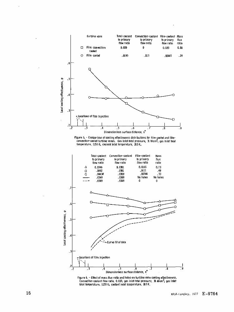
Figure 5 shows the cooling effectiveness distributions for both film cooling by itselfand combined film-convection cooling, each for the same total coolant flow. The film-cooled vane has a film-coolant to primary flow ratio of 0. 02 (mass flux ratio of 0. 88) butno convection cooling. As expected, the vane cooling effectiveness decreases with thedistance from the film-cooling holes. The other cooling effectiveness distribution is fora combination of a film-coolant to primary flow ratio of 0. 007 (mass flux ratio of 0. 29)and a convection-coolant to primary flow ratio of 0. 013. This effectiveness distributionis uniform over the entire surface. Near the leading edge, the vane is film cooled; nearthe trailing edge, the vane is convection cooled. For this comparison the average ef-fectiveness for the film-convection-cooled vane is 0. 38, compared with 0. 35 for theconvection-cooled vane. Thus, the film-convection-cooled vane is the more effectivelycooled vane in spite of the fact that the comparison is biased in favor of the film-cooledvane. That is, the coolant that was diverted from film cooling the pressure surface mustconvection cool both the pressure and suction surfaces. The conclusion that can bedrawn from figure 5 is that a combination of film and convection cooling is more effec-tive, on the average, than film cooling alone for the same total coolant flow.
Favorable Effect of Film Cooling
Figure 6 presents a chordwise distribution of cooling effectiveness for a convection-cooled vane with a convection-coolant to primary flow ratio of about 0. 037. It also pre-sents similar distributions for a film-convection-cooled turbine vane with mass fluxratios of 0, 0. 33, 0. 49, and 0. 73, all having a convection-coolant to primary flow ratioof about 0. 037. The data show increasing cooling effectiveness with increasing mass
8
flux ratio; that is, the vane cooling effectiveness did not decrease below that of theconvection-cooled vane when small quantities of air were injected into the boundarylayer as had occurred on the suction surface of this vane (refs. 2 and 5).
In reference 2, a small amount of film-cooling airflow caused a laminar or tran-sitional boundary layer to become transitional or turbulent, with an accompanying in-crease in the gas-side heat transfer coefficient. The effect of the increase in the heattransfer coefficient was greater than the increased benefits of film cooling. As a re-sult, the local temperatures increased when small amounts of coolant were injected intothe boundary layer. For the present study, the boundary layer on the pressure surfaceis already turbulent. As a result, the cool film in the boundary layer more than com-pensates for any increase in the heat transfer coefficient that accompanies a smallamount of film injection from discrete holes. Therefore, at small values of mass fluxratio the cooling effectiveness on the pressure surface of a turbine vane always in-creased relative to the zero-injection case, in contrast to what had been formerly ob-served on the suction surface of the same vane.
Adverse Effect of Holes
Data were also taken both without film-cooling holes and with film-cooling holes butwithout film injection. These results, some of which are included in figure 6, show thatthe presence of film-cooling holes at 1/4 chord length from the leading edge, but withoutfilm injection, resulted in decreased cooling effectiveness along the entire pressure sur-face when compared with the same vane without holes. Therefore, to obtain a beneficialeffect of film cooling relative to convection cooling, the injected film must exceed a cer-tain threshold value. Below this value the cooling effect of the film is insufficient toovercome the roughness effect of the holes.
It is possible, though unlikely, that this adverse effect of holes may be the resultof the recirculation of hot gas in through the holes at the hub and out through the holesat the tip. However, the test facility used for this investigation performed more as atwo-dimensional cascade than as a three-dimensional cascade. As a result, very littlespanwise static pressure gradient exists to cause recirculation of the hot gas. Surfacestatic pressure distributions for this vane are presented in reference 9. They showless than a 2-percent difference between the hub and tip static pressures.
In any event, a threshold value of injected film is required to cool the vane to thecondition that existed before holes were added. As shown in figure 4, the thresholdmass flux ratio was about 0. 23.

SUMMARY OF RESULTS
An investigation into the effects of film cooling on wall temperatures on the pres-sure surface of a turbine vane gave the following results:
1. On the average, a turbine vane was more effectively cooled by a combination offilm and convection cooling than by either film or convection cooling separately for massflux ratios greater than a threshold value of about 0. 23.
2. Adding small quantities of film-cooling air always increased the cooling effec-tiveness on the pressure surface of a turbine vane relative to the zero-injection case.This is in contrast to what had been formerly observed on the suction surface of thesame vane.
3. The presence of film-cooling holes at 1/4 chord length from the leading edge,but without film injection, resulted in decreased cooling effectiveness along the entirepressure surface when compared with the same vane without the film-cooling holes.Therefore, to obtain a beneficial effect of film cooling relative to convection cooling,the injected film must exceed a certain threshold value. Below this value the coolingeffect of the film is insufficient to overcome the roughness effect of the holes.
Lewis Research Center,National Aeronautics and Space Administration,
Cleveland, Ohio, February 9, 1977,505-04.
REFERENCES
1. Colladay, Raymond S.: Analysis and Comparison of Wall Cooling Schemes for Ad-vanced Gas Turbine Applications. NASA TN D-6633, 1972.
2. Gladden, Herbert J.; and Gauntner, James W.: An Adverse Effect of Film Coolingon the Suction Surface of a Turbine Vane. NASA TN D-7618, 1974.
3. Yeh, Frederick C.; et al.: Comparison of Cooling Effectiveness of Turbine Vaneswith and without Film Cooling. NASA TM X-3022, 1974.
4. Lander, R. D.; Fish, R. W.; and Suo, M.: The External Heat Transfer Distribu-tion on Film-Cooled Turbine Vanes. AIAA Paper 72-9, Jan. 1972.
5. Gladden, H. J.; and Gauntner, J. W.: Experimental Verification of Film-CoolingConcepts on a Turbine Vane. ASME Paper 75-WA/GT-21, Nov./Dec. 1975.
6. Calvert, Howard F.; et al.: Turbine Cooling Research Facility. NASA TM X-1927,1970.
10

7. Growl, Robert J.; and Gladden, Herbert J.: Methods and Procedures for Evaluating,Forming, and Installing Small-Diameter Sheathed Thermocouple Wire and SheathedThermocouples. NASA TM X-2377, 1971.
8. Colladay, Raymond S.; and Stepka, Francis S. : Similarity Constraints in Testing.of Cooled Engine Parts. NASA TN D-7707, 1974.
9. Gladden, Herbert J.; et al.: Aerodynamic Investigation of Four-Vane Cascade De-signed for Turbine Cooling Studies. NASA TM X-1954, 1970.
TABLE I. - THERMOCOUPLE LOCATION
Thermo-couple
Distance fromleading edge,
cm
Dimension-less loca-
tion
Vane wallthickness,
cm
Pressure surface, L = 6. 53 cm
a91011
12
1314
15
1.072.102.773.62
.4.334.935.58
0.163.321.424.554.663.755.854
0.152.254.254.254.254. 191. 127
Film-cooling holes were located between thermo-couples 9 and 10, at 1.60 and 1.85 cm from lead-ing edge (0. 245 and 0. 284 dimensionless loca-tion).
11

TABLE II. - Concluded.
Read-
ing
666768697071
7273747576777879808182838485868788899091
9293949596979899
100101102
103104105106107108109110111112113114115
116117
118119120
121122123124
125126127
128129130131
132133
Gas totalinlet
tempera-ture,
K
125812641261
1274
12741277
127512811281
1282128612831283128312871280127812791279
128312661266126212641263
1268126412621264
1263128612871284
128312831284128612881287128612881273127412721260126012591259
127212741273
1278127812671265
12701270126812631264125912601250
12761277128212771275
Gas totalinlet
pressure,N/cm2
31.0
T-31.0
45.5
Gas flow
per vane
channel,kg/hr
1670
t
-1670
2450
Coolant
inlet
temper-
ature,K
281281293
293292292291290289289288
1
\292292291290289
289294293290289289292291290289289
287
r286
1
286285
1
290
289
284
293293
292
Convection-coolant to
primary
flow ratio
0.01365.00199.0628.0534
.0521
.0458
.0308
.0234
.0185
.0147
. 00942
. 00524
.00167
. 00063
.0550
.0442
.0407
.0318
.0177
.0105
.0526
.0420
.0119
. 00653
. 003570
. 00490.00547
.00541
.00559
. 00747
. 00762
.00759
.00761
.0128
.0129
.0130
.0129
.0131
.0131.0130.0129.0131
.0384
.0381
.0381
.0382
.0381
.0368
.0369
.0377
Film -coolantto pr mary
gas flow ratio
No holes
0
.0200
.0144
.0101
. 00660
. 00493
.0128
. 00698
. 00979
. 00605
. 00398
. 00528
.00765
. 00935
.0106
.0107
. 00892
. 00645
.00517
.00285
.00416
. 00539
. 00686
. 00858
.00519
.00757
.0111
.0130
.0165
. 00890
. 00744
. 00595292 .0397 .00428292 , .0399 | .00283281
294
.01474
. 02053
. 03040
. 03807
.00156- .0240
.0241
No holes
T
0.00651. 00784
. 0240 . 00962
! t .0241 .0117T T i 295 .0242 .0137
Thermocouple location (fig. 2)
9 10 11 12 13 14 15
Vane wall temperature, K
1203123811461150
11541160
11751186
119211991209
1214122712331169
1172117211851200121311501157117811921194
881940992
10981177951
107310001104
118511351033
998976973
1003105511261177115011071036997
11091009
952931
896989
1016
1070113511501207
119811951185
123710541007970
10741224889
912918939993
1029
1054107811131147
11861219
10131220782807
814838904
950984
1017
1064
111211681220
923 j 815945955993
10591106921952
108511311159722800
88810471159
765954841
99411001026885
829794767810
897986
1067
1034970877819
878754673645
604730769
833.920
94310591019
973939
1223829767710
940 666
914 635
843855900987
1052819856
103010911132
833910983
1093
1163840980899
100410771014926884857815848
904958
1015986948893853815746689668
631734759
793842857997
946891852
1220
826787
748115
688
9601215
723746752775841889
926962
1015
107411441214754
782793839930
1002755791977
10481100
931995
105011281172887987930
10021047998941910890838862897930968
948926891864
773733695680
652728745
763790797951
898840800
1218823797769745
725
9411197713789
739759820
865900935988
104711201191743
766777819906977744776
95210231077985
1034107411291158
917989947
9981030989949
927912857874
896920946930
916892
873768740712701
680737749
760779783938
9061185
682704709730793842
878917971
103511111184713737749793886960709742932
100610631021105310851130
1154925985949
9901017978945928915852867884903924
910899880
864737715692685669714723
732
745749917
887 864833798
1204826808788770
755
808770
1196804789773758
746
9101183664685691
713782
833870909964
103011081179697
722735783882957679715921
10001059
10291065109311331153
933986953989
1012974945929917849
862878895913900891874860
714695673673660694703
709
721723899
843781735
1200791778763750740
12

TABLE n. - PRESSURE-SURFACE DATA
Read-
ing
12
3
4
5
6
7
8
9
10
11
12
13
14
15
16
n18
19
20
21
22
23
24
25
26
27
28
29
30
31
32
33
34
35
36
37
38
39
40
41
42
43
44
45
46
47
48
49
50
51
52
53
54
55
56
57
58
59
60
61
62
63
64
65
Gas totalInlet
tempera-ture,
K
1248125212581262
126112601259125612851283128312841284126612651266126812671267
1268128312841283128412611268126712681267126812681275127612751274126612671262126912621283128612871287
128612671263126412641259126012571260125512721271
1273126812681267
126912671265
12621257
Gas totalInlet
pressure,N/cm2
22.7
~22.7
25.5
31.031.031.0
Gas flowper vanechannel,
kg/hr
1230
-1230
1380
1670
16701670
CoolantInlet
temper-ature,
K
284
284
282
282
281
281
281
281
283
284
290
289
288
284
1
1289
289
289
288
288
288
289
288
290
283
283
284
283
291
292
I
1
281
290
291
290
281
280
281
Convection-coolant toprimary
flow ratio
0.00813.01536.03363.04681. 04650. 04272. 03546. 02664.0461.0377.0249.0169
. 009760
.00979
. 00976
.00916
. 00944
. 00954
.00975
. 00958
. 00952
.00958
. 00969
.00951
. 00954
.00964
. 00962
. 00956
.0126
.0129
.0132
.0132
.0133
.0337
.0342
.0341
.0338
.0334
.0334
.0338
.0341
.0340
.01393
.02218
.03211
.04029
.00042
.0239
.0246
.0241
.0240
.0237
.0238
.0238
.0238
.02007
.02791
. 03633
Film-coolantto primary
gas flow ratio
No holes
0
.0276.0186.0141
.00967
.00663
. 00554
. 00434
.00756
. 00928
.0156
.0198
.00326
.00417
. 00549
. 00750
.00951
.0115
. 00454
.00531
.0102
.0135
.0150
.0176
.0126
.0095
. 00693
. 00454
.0198
.0149
.0111
. 00797
.00318
. 00363
.00471
. 00662
.00871No holes
0.0175.0130.0107. 00908.00774.00623.00521.00268
No holesNo holesNo holes
Thermocouple location (fig. 2)
9 10 11 12 13 14 15
Vane wall temperature, K
118811821165115511551157116011731180118511991209
1221849
924
969
103411201178120110591023938
899
11881155113810551020995
116411451008965
946
918
970
999
10631150893
938
984
10321159115411381054
1011119411801170
11611226911
952
983
10031025
108311371160
119711891179
1092
1052974
927
927
940
961
1004
975
100010541017
1142717
800
959
958
108011551190
922
867
749
702
110610881033925
872
832
10691040852
790
765
719
784
837
923
1040634
681
735
807
983
976
950
849
788
10751021974
942
1214669
717
763
797
834
905
974
10121035
993
959
1043988
884
827
826
842
869
922
870
903
973
10301092
811
900
955
1035
11211164
1190945
904
804
758
106010431008
943
905
877
10281011890
839
817
767
825
863
925
992
654
699
744
795
898
892
874
816
779
1015944
884
844
1212703
744
782
804
828
872
911
939
959
907
865
991
928
815
755
753
769
798
855
794
828
903
968
1039905
985
10301090115011781194948
919
844
805
10191007988
947
920
900
997
989
909
870
853
804
849
873
918
956
675
710
743
778
837
834
824
789
768
960
882
817
776
1204730
760
788
804
819
847
869
884
901
845
802
969
906
795
738
736
751
778
833
772
804
877
940
1012962
10241059110311451163
1174950
929
873
844
993
983
972
944
925
911
977
989
918
889
877
832
865
879
913
935
703
728
753
777
814
812
804
782
768
939
862
799
761
1185754
775
797
807
817
837
850
860
884
830
791
956
890
774
715
713
729
756
813
739
772
848
917
993
992
10441074111111461160
1168944
927
880
855
977
969
961
939
923
911
965
963
917
894
882
838
864
874
904
920
697
718
737
756
785
784
778
760
750
921
843
777
738
1174750
767
785
794
801
817
829
835
864
807
765
945
875
752
686
685
701
731
795
713
748
833
904
985
100510541082111511481160
1167942
925
882
859
972
964
957
937
922
910
960
959
916
894
883
837
862
870
899
913
687
705
722
740
767
766
760
744'
735
908
826
754
710
1170744
759
777
784
791
806
817
822
847
785
736
13

Exit flowdirection
Flow channel-
Test vane -Inlet flowdirection
Figure 1. - Schematic of cascade test section.
r Film-cooling-air supply plenum
r Film-cooling holes\\v\ r-Impingement cooling
-Thermocouple
v Pin-fin cooling
\ \
CD-11135-33- Midchord supply tube
Figure 2. - Cross-sectional midspan view showing internal cooling scheme and thermocouple locations.
14

- ,s;s *5r I « 8°̂ " ™* = g>°§s.I IJSJ
s 8 OR-
8I B
E3
i ?^^IE S-§"S = Q- §c "2 15 ,.0 ^ •*•* O-S CO £ ^— -o >0
S--I-S5 ' "> p"u C eg >-
1 o O 2^f 13 .2
£ S S £
as II
6 'ssauaAjpaya 6u!|oo> aBejaAy
S
2^ e
13 c Sa. s^I si~ S-ro .— -n
€ 8 =
3 i-O <D
S i i
I I
15
Turbine vane
D Film convectioncooled
O Film cooled
Tola I-coolantto primaryflow ratio
0.020
.0195
Convection-coolantto primaryflow ratio
.013
Film-coolant Massto primary fluxflow ratio ratio
0.020 0.88
.00645 .29
.3 .4 .5 .6 .7
Dimensionless surface distance, x°.9
Figure 5. - Comparison of cooling effectiveness distributions for film-cooled and film-convection-cooled turbine vanes. Gas inlet total pressure. 31 N/cm2; gas inlet totaltemperature, 1255 K; coolant inlet temperature, 283 K.
A
D0
Total-coolant Convection-coolantto primary to primaryflow ratio flow ratio
0.0546.0492.04434.0369.0369
0.0381.0381.0369.0369.0369
Film-coolant Massto primary fluxflow ratio ratio
0.0165.0111.00744
No holes0
0.73.49.33
No holes0
1
I
83
.4
•-Curve fit of data
r Locations of film injection
i ,.2 .3 .4 .5 .6 .7
Dimensionless surface distance, x*.9
Figure 6. - Effect of mass flux ratio and holes on turbine vane cooling effectiveness.Convection-coolant flow ratio. 0.037; gas inlet total pressure. 31 Nfcrn2; gas inlettotal temperature, 1255 K; coolant inlet temperature, 283 K.
16 NASA-Langley, 1977 E-8764

NATIONAL AERONAUTICS AND SPACE ADMINISTRATION
WASHINGTON. D.C. 2O546
OFFICIAL BUSINESS
PENALTY FOR PRIVATE USE *3OO
POSTAGE AND FEES PAIDNATIONAL AERONAUTICS AND
SPECIAL FOURTH-CLASS RATEBOOK
POSTMASTER : If Undeliverable (Section 158Postal Manual) Do Not Return
'The aeronautical and space activities of the United States shall beconducted so as to contribute . . . to the expansion of human knowl-edge of phenomena in the atmosphere and space. The Administrationshall provide for the widest practicable and appropriate disseminationof information concerning its activities and the results thereof."
—NATIONAL AERONAUTICS AND SPACE ACT OF 1958
NASA SCIENTIFIC AND TECHNICAL PUBLICATIONSTECHNICAL REPORTS: Scientific andtechnical information considered important,complete, and a lasting contribution to existingknowledge.
TECHNICAL NOTES: Information less broadin scope but nevertheless of importance as acontribution to existing knowledge.
TECHNICAL MEMORANDUMS:Information receiving limited distributionbecause of preliminary data, security classifica-tion, or other reasons. Also includes conferenceproceedings with either limited or unlimiteddistribution.
CONTRACTOR REPORTS: Scientific andtechnical information generated under a NASAcontract or grant and considered an importantcontribution to existing knowledge.
TECHNICAL TRANSLATIONS: Informationpublished in a foreign language consideredto merit NASA distribution in English.
SPECIAL PUBLICATIONS: Informationderived from or of value to NASA activities.Publications include final reports of majorprojects, monographs, data compilations,handbooks, sourcebooks, and specialbibliographies.
TECHNOLOGY UTILIZATIONPUBLICATIONS: Information on technologyused by NASA that may be of particularinterest in commercial and other non-aerospaceapplications. Publications include Tech Briefs,Technology Utilization Reports andTechnology Surveys.
Details on the availability of these publications may be obtained from:
SCIENTIFIC AND TECHNICAL INFORMATION OFFICE
NATIONAL A E R O N A U T I C S A N D S P A C E A D M I N I S T R A T I O NWashington, D.C. 20546