downloads.semi.orgdownloads.semi.org/.../$FILE/ATTJFT6O.docx · Web viewMuch of the handle...
70
Background Statement for SEMI Draft Document 5009C Line Item Revisions to SEMI S8-0712a, SAFETY GUIDELINES FOR ERGONOMICS ENGINEERING OF SEMICONDUCTOR MANUFACTURING EQUIPMENT Delayed Revisions on Multiple Topics Notice: This background statement is not part of the balloted item. It is provided solely to assist the recipient in reaching an informed decision based on the rationale of the activity that preceded the creation of this Document. Notice: Recipients of this Document are invited to submit, with their comments, notification of any relevant patented technology or copyrighted items of which they are aware and to provide supporting documentation. In this context, “patented technology” is defined as technology for which a patent has issued or has been applied for. In the latter case, only publicly available information on the contents of the patent application is to be provided. Background Statement This ballot consists of three (3) line items. Each line item is shown as a separate section with subcategories. Line item 1 (X) – Ergonomics clearances clarification. These changes are intended to better define ergonomics-related clearances for equipment design and installation. Line item 2 (Y) – Modifications to Appendix 1, SESC checklist, Section 6 enclosed handle design guidelines to allow for a wider range of acceptable handle shapes and sizes. Line item 3 (Z) – Modifications to Appendix 1, SESC checklist, Section 7 to expand whole body clearance criteria to include equipment operation tasks and provide design criteria for a seated posture. Whole body clearance recommendations are separated into two categories: walking/crawling and working postures. Existing recommendations specific to maintenance and service tasks are moved to a new Section 11. As this is a technical ballot, all votes of reject must be accompanied by reasons (negatives) and also be sent to SEMI staff before the balloting deadline or they will be considered abstention votes. If you have any comments on the ballot (suggestions or questions that you do not believe are technical negatives) please clearly indicate them as COMMENTS to assist us with reducing the administrative overhead in handling them during the task force and committee meetings. Additional Background Information for the Document The proposed changes add design recommendations to fill gaps in the original SEMI-S8 document and are intended to improve usability of the guidelines. The
Transcript of downloads.semi.orgdownloads.semi.org/.../$FILE/ATTJFT6O.docx · Web viewMuch of the handle...

Background Statement for SEMI Draft Document 5009CLine Item Revisions to SEMI S8-0712a, SAFETY GUIDELINES FOR ERGONOMICS ENGINEERING OF SEMICONDUCTOR MANUFACTURING EQUIPMENTDelayed Revisions on Multiple TopicsNotice: This background statement is not part of the balloted item. It is provided solely to assist the recipient in reaching an informed decision based on the rationale of the activity that preceded the creation of this Document.
Notice: Recipients of this Document are invited to submit, with their comments, notification of any relevant patented technology or copyrighted items of which they are aware and to provide supporting documentation. In this context, “patented technology” is defined as technology for which a patent has issued or has been applied for. In the latter case, only publicly available information on the contents of the patent application is to be provided.
Background StatementThis ballot consists of three (3) line items. Each line item is shown as a separate section with subcategories.
Line item 1 (X) – Ergonomics clearances clarification. These changes are intended to better define ergonomics-related clearances for equipment design and installation.
Line item 2 (Y) – Modifications to Appendix 1, SESC checklist, Section 6 enclosed handle design guidelines to allow for a wider range of acceptable handle shapes and sizes.
Line item 3 (Z) – Modifications to Appendix 1, SESC checklist, Section 7 to expand whole body clearance criteria to include equipment operation tasks and provide design criteria for a seated posture. Whole body clearance recommendations are separated into two categories: walking/crawling and working postures. Existing recommendations specific to maintenance and service tasks are moved to a new Section 11.
As this is a technical ballot, all votes of reject must be accompanied by reasons (negatives) and also be sent to SEMI staff before the balloting deadline or they will be considered abstention votes. If you have any comments on the ballot (suggestions or questions that you do not believe are technical negatives) please clearly indicate them as COMMENTS to assist us with reducing the administrative overhead in handling them during the task force and committee meetings.
Additional Background Information for the Document The proposed changes add design recommendations to fill gaps in the original SEMI-S8 document and are intended to improve usability of the guidelines. The proposed changes were developed during SEMI-S8 Task Force activities which have been ongoing since March of 2008.

Calculations and Rationale for Line Item 2 Proposal: Modifications to Appendix 1, SESC, Section 6 Enclosed Handle Design Guidelines
1. Background
There have been many complaints from SEMI EHS committee members about limitations of the current handle design guidance in SEMI-S8 Appendix 1, Supplier Ergonomic Success Criteria (SESC), Section 6 including restrictive values, inability to find commercially available handles that meet the design criteria for 4-finger enclosed handles, and how to risk-rank handles that do not conform to the provided criteria.
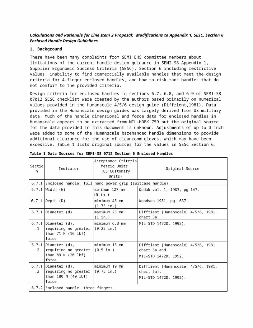
Design criteria for enclosed handles in sections 6.7, 6.8, and 6.9 of SEMI-S8 07012 SESC checklist were created by the authors based primarily on numerical values provided in the Humanscale 4/5/6 design guide (Diffrient,1981). Data provided in the Humanscale design guides was largely derived from US military data. Much of the handle dimensional and force data for enclosed handles in Humanscale appears to be extracted from MIL-HDBK 759 but the original source for the data provided in this document is unknown. Adjustments of up to ½ inch were added to some of the Humanscale barehanded handle dimensions to provide additional clearance for the use of cleanroom gloves, which may have been excessive. Table 1 lists original sources for the values in SESC Section 6.
Table 1 Data Sources for SEMI-S8 0712 Section 6 Enclosed Handles
Section IndicatorAcceptance Criteria
Metric Units (US Customary Units)
Original Source
6.7.1 Enclosed handle, full hand power grip (suitcase handle)6.7.1 Width (W) minimum 127 mm (5 in.) Kodak vol. 1, 1983, pg 147.
6.7.1 Depth (D) minimum 45 mm (1.75 in.) Woodson 1981, pg. 637.6.7.1 Diameter (d) maximum 25 mm (1 in.) Diffrient [Humanscale] 4/5/6, 1981, chart 5a.
6.7.1.1 Diameter (d), requiring no greater than 71 N (16 lbf) force
minimum 6.3 mm (0.25 in.) MIL-STD 1472D, 1992).
6.7.1.2 Diameter (d), requiring no greater than 89 N (20 lbf) force
minimum 13 mm (0.5 in.) Diffrient [Humanscale] 4/5/6, 1981, chart 5a andMIL-STD 1472D, 1992.
6.7.1.3 Diameter (d), requiring no greater than 180 N (40 lbf) force
minimum 19 mm (0.75 in.) Diffrient [Humanscale] 4/5/6, 1981, chart 5a).MIL-STD 1472D, 1992).
6.7.2 Enclosed handle, three fingers
6.7.2 Enclosed handle, three fingersWidth (W)
minimum 90 mm (3.5 in.) Diffrient [Humanscale] 4/5/6, 1981, chart 6b individual finger sizes 95th-97.5th percentile male finger widths summed and adjusted up for gloves. Index (0.9) + Middle (1.0) + Ring finger widths (0.9) = 2.8 in. + 0.5 glove adjustment = 3.3 in.
6.7.2 Depth (D) minimum 38 mm (1.5 in.) Diffrient [Humanscale] 4/5/6, 1981, chart 5A) cylinder handle.
6.7.2 Diameter (d) minimum 6.3 mm (0.25 in.) Could not find source6.7.2 Force maximum 71 N (16 lbf) Could not find source6.7.3 Enclosed handle, two fingers6.7.3 Width (W) minimum 60 mm (2.5 in.) MIL-STD 1472D, 1992, (ungloved) pg. 204, fig. 48.
6.7.3 Depth (D) minimum 38 mm (1.5 in.) MIL-STD 1472D, 1992 (gloved) pg. 204, Fig. 48.
6.7.3 Diameter (d) minimum 6.3 mm (0.25 in.) MIL-STD 1472D, 1992, (ungloved) pg. 204, fig. 48.
6.7.3 Force maximum 51 N (11.5 lbf) Could not find source
6.7.4 Enclosed handle, one finger
6.7.4 Width (W) minimum 38 mm (1.5 in.) Individual finger sizes for 95th-97.5th percentile male index finger width (Diffrient [Humanscale] 4/5/6, 1981, chart 6B) used and adjusted up for gloves.

Section IndicatorAcceptance Criteria
Metric Units (US Customary Units)
Original Source
6.7.4 Depth (D) minimum 38 mm (1.5 in.) Diffrient [Humanscale], 1981, chart 5A) Cylinder handle minimum depth of 38 mm (1.5 in) (appears to have been used, with no adjustment for gloves).
6.7.4 Diameter (d) minimum 3.2 mm (0.13 in.) Could not find source6.7.4 Force maximum 27 N (6 lbf) Could not find source6.8 Hook grasp handle
6.8.1 Hook grasp handle (four fingers)Opening length (L)
minimum 90 mm (3.5 in.) Diffrient [Humanscale] 4/5/6, 1981, chart 5a).
6.8.1 Opening width (W) minimum 38 mm (1.5 in.) Diffrient [Humanscale] 4/5/6, 1981 (gloved hand), chart 5a). 38 mm (1.5 in.) (Konz, 2004, pg. 273).
6.8.1 Depth (d) minimum 50 mm (2 in.) Diffrient [Humanscale] 4/5/6, 1981 [gloved hand], chart 5a)
6.8.1 Lip length (l) minimum 50 mm (2 in.) Gloved and ungloved (Diffrient [Humanscale] 4/5/6, 1981, chart 5a).
6.8.2 Hook grasp handle pull force (four fingers)
maximum 80 N (18 lbf) Could not find source
6.9 Finger pull handle6.9.1 Finger pull handles (four
fingers)Opening length (L)
minimum 90 mm (3.5 in.) Gloved/ bare hand (Diffrient [Humanscale] 4/5/6, 1981, chart 5a).
6.9.1 Opening width (W) minimum 25 mm (1 in.) Diffrient [Humanscale] 4/5/6, 1981, chart 5a) (gloved hand).
6.9.1 Depth (d) minimum 19 mm (0.75 in.) (Diffrient [Humanscale] 4/5/6, 1981, chart 5a) (ungloved hand).
6.9.1 Lip length (l) minimum 19 mm (0.75 in.) Appears to be a cut and paste error. Humanscale 5A recommendation is 13 mm (0.5 in.).
6.9.2 Finger pull handles pull force (four fingers)
maximum 9.8 N (2.2 lbf) Could not find source.
2. Overview of Proposed System
A design guideline for enclosed, hook grip and finger grip handles was created to replace the current design guidelines in SESC Section 6. The new system is based on clearance for a large (95th percentile male) hand and pressure (kPa) for a small (5th percentile female) hand with adjustments for gloved conditions typically found in the semiconductor manufacturing industry. This system has the following advantages over the current “power” grip, hook grip, and finger-pull handle design guidelines provided in SESC Section 6.
A. Can be used to design or specify new handles for semiconductor manufacturing equipment and assess existing handles.
B. Allows for “downgrading” of sub-optimal handles based on force requirements.a. If a handle’s opening height isn’t high enough for full finger encirclement then it may be suitable for a
“hook” or a “fingertip” grip provided the measured forces don’t exceed maximum recommendations for that (hook grip or fingertip grip) configuration.Note: Downgrading of the handle opening width is possible within the current system but this only works for enclosed handles.
C. Can be used to assess handles with rectangular or oval cross-sections.D. Provides allowances for bare hand and various gloved hand conditions.
a. In some environments (IC testing, for example) gloves are not normally worn by equipment operators and technicians so allowances for glove thickness are not necessary.
E. Provides allowances for anticipated frequency of use (machine operation versus maintenance/service).
DRAFTDocument Number:
Date: 5/8/23
This is a Draft Document of the SEMI International Standards program. No material on this page is to be construed as an official or adopted Standard or Safety Guideline. Permission is granted to reproduce and/or distribute this document, in whole or in part, only within the scope of SEMI International Standards committee (document development) activity. All other reproduction and/or distribution without the prior written consent of SEMI is prohibited.
Page 1 Doc. jn l SEMI
Semiconductor Equipment and Materials International3081 Zanker RoadSan Jose, CA 95134-2127Phone: 408.943.6900, Fax: 408.943.7943

3. Enclosed Handle Assessment System Parameters
The proposed handle assessment system is based on the understandings listed below. A. Finger clearance. Clearance dimensions accommodate the 95th percentile US male hand (Garret, 1971)
plus an allowance for ease of hand insertion and deformation of the hand when force is applied. Clearance values were rounded up as appropriate (see Table 2).
Table 2 Hand Measurements for the 95th Percentile Male and Clearance Dimensions
Joint Measurement Digit 2 Digit 3 Digit 4 Digit 5Metacarpal-phalangeal (MCP) joint
Actual joint depth -- 36.1 mm -- --
Joint depth w/ clearance -- 45.0 mm -- --
Proximal interphalangeal (PIP) joint
Finger width actual 23.7 mm 24.1 mm 22.3 mm 20.1 mm
Finger width clearance(cumulative)
30.0 mm 60.0 mm 90.0 mm 110.0 mm
Finger depth w/ straight finger
-- 22.6 mm -- --
Distal interphalangeal (DIP) joint
Finger width 20.3 mm 20.3 mm 19.2 mm 17.6 mm
Finger width clearance(cumulative)
25.0 mm 50.0 mm 70.0 mm 85.0 mm
Finger depth w/ straight finger
-- 18.0 mm -- --
Finger depth w/ clearance -- 25.0 mm -- --
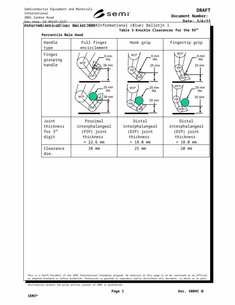
Knuckle clearances were estimated by modeling a 95th percentile male hand grasping 6 mm and 25mm-diameter handles using CAD software for full finger encirclement, hook grip, and fingertip grip conditions (see Table 3). Allowances were made for finger insertion and hand deformation when force is applied.
Table 3 Knuckle Clearances for the 95th Percentile Male Hand
Handle type Full finger encirclement Hook grip Fingertip gripFinger grasping handle
Joint thickness for 3rd digit
Proximal interphalangeal (PIP) joint thickness
= 22.6 mm
Distal interphalangeal (DIP) joint thickness
= 18.0 mm
Distal interphalangeal (DIP) joint thickness
= 18.0 mmClearance dim. 38 mm 25 mm 20 mm

Lip lengths for hook and fingertip grip handles were estimated using finger segment lengths for the 95th percentile male hand. Length of the 95th percentile male hand is 211.6 mm (Garret, 1970). Length of 3rd digit middle segment is 15.8% (33.2 mm) and the length of the distal segment is 9.8% (20.6 mm) of hand length (Freivalds, 2000). The center of rotation of the finger joint is near the middle of the joint. When a finger segment is flexed 90 degrees, the segment length is assumed to be shortened by about half of the thickness of the joint. Therefore, half of the thicknesses of the proximal interphalangeal (PIP) and distal interphalangeal (DIP) joints were subtracted in the formulas used to determine handle lip lengths shown below. See Table 4 for a depiction. MCP is the metacarpal phalangeal joint.
a. Hook grip lip length: Middle segment + distal segment + fingernail – (½ × PIP thickness) = lip length33.2 mm + 20.6 mm + 3 mm – (½ × 22.6 mm) = 45.5 mm (rounded up to 46 mm)
b. Fingertip grip lip length: Distal segment + fingernail – (½ × DIP thickness) = lip length20.6 mm + 3 mm – (½ × 18 mm) = 14.6 mm (rounded up to 15 mm)
Table 4 Lip Length Clearances (Bare Hand)
Handle type Hook grip Fingertip grip
Finger section(s) engaging handles
B. Gloved hand conditions. Provisions have been made for gloved and ungloved conditions anticipated by the SME supplier since gloved and non-gloved conditions exist in semiconductor processing facilities.
a. Gloves are not worn in some wafer fab support and assembly/test areas so bare hands are used.b. Cleanroom gloves are typically worn in semiconductor wafer fabrication facilities.
i. Knit liners are commonly worn under cleanroom gloves to absorb and wick perspiration and to provide insulation for some thermal processes. These liners add to the thickness of gloved hands and digits.
c. Chemically resistant gloves are worn to protect workers from chemical hazards.d. Electrical insulating gloves with leather over-gloves are worn to protect workers from electrical
hazards.e. Thermal insulating gloves are worn to protect workers from thermal hazards.
Glove allowances have been added to bare hand clearance dimensions of each gloved condition. For finger insertion dimensions, glove allowances were added to both sides of each finger. For example, if the handle is intended to accommodate 3 fingers then six glove thicknesses were added to the clearance dimension for 3 fingers. Glove measurements were collected from wafer fab employees at Texas Instruments (see Table 5).
Table 5: Gloved Hand MeasurementsCondition Bare hand Cleanroom (Nitrile)
glove with knit Nylon liner
Chemical glove over cleanroom glove
Electrical insulating glove
Thermal insulating glove
Image
One side 0 mm (0 in.) 1.5 mm (0.12 in.) 3 mm (0.12 in.) 6 mm (0.25 in.) 6 mm (0.25 in.)Two sides 0 mm (0 in.) 3 mm (0.12 in.) 6 mm (0.25 in.) 12 mm (0.5 in.) 12 mm (0.5 in.)
C. Force pressures. Skin contact pressure values were used to determine maximum recommended forces for handles. Pushing, pulling, and lifting a handle involves gripping the handle while applying force to perform the intended task.
a. Machine operation tasks: maximum contact pressure against fingers = 70.5 kPa (10.2 psi). This is an average of a sustained externally applied surface pressure deemed acceptable for a full workday by male 104 kPa (15.1 psi) and female 37 kPa (5.4 psi) test subjects (Fransson-Hall, 1993). The work pace in semiconductor manufacturing facilities is generally slower than general manufacturing so rest-recovery cycles are longer. Therefore, an average of male and female force preferences was chosen over the female preferences.
b. Machine maintenance and service tasks: maximum contact pressure against fingers = 188 kPa (27.3 psi) average pressure-discomfort threshold (PDT) for 24 male and female test subjects (Johansson, 1999).
D. Pressure distribution. Finger contact area for a 5th percentile Japanese female hand (Human Hand Dimension for Ergonomic Design, 2010) was used to calculate pressure distribution area for hand-handle interfaces for full finger encirclement (power grip), hook grip, and fingertip grip handles.
a. For the full finger encirclement handle, cumulative digit width at the proximal interphalangeal (PIP) joints was used.
b. For the hook grip handle, cumulative digit width at the distal interphalangeal (DIP) joints was used.
c. Fingertip contact area for each finger is assumed to be round. For the finger grip handle, fingertip contact area was calculated using the circle area formula below and the values were summed for the fingers involved.
(π × [{DIP joint width}/2]2 )
Table 6 Finger Joint Widths for the 5th Percentile Japanese Female
Measurement Digit 2 Digit 3 Digit 4 Digit 5PIP joint width 15.35 mm 15.16 mm 14.30 mm 12.41 mm
DIP joint width 13.58 mm 13.54 mm 12.65 mm 11.27 mm
E. Full finger encirclement (power grip) hand-handle interface surface. Maximum achievable gripping force on a cylinder is attained when the fingers fully encircle the cylinder with the fingers and thumb overlapping. Seo, et al. (2007) estimated the optimum grip diameter to be a cylinder where the thumb and index finger overlap by ½ the length of the distal phalanges of these digits. Grant, et al. (1992) determined the optimum overlap to be about 1 cm although the exact amount is not known because of the limited diameters of cylinders tested. Full handle encirclement also has the added benefit of allowing the hand to rotate around the handle allowing the wrist of the user to remain neutral or nearly neutral throughout the range of motion.

Direction of force Direction of force
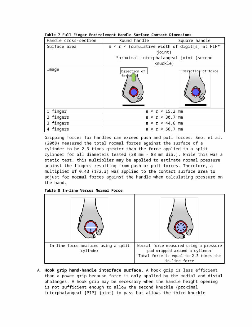
Table 7 Full Finger Encirclement Handle Surface Contact DimensionsHandle cross-section Round handle Square handleSurface area π × r × (cumulative width of digit[s] at PIP* joint)
*proximal interphalangeal joint (second knuckle)Image
1 finger π × r × 15.2 mm2 fingers π × r × 30.7 mm3 fingers π × r × 44.6 mm4 fingers π × r × 56.7 mm
Gripping forces for handles can exceed push and pull forces. Seo, et al. (2008) measured the total normal forces against the surface of a cylinder to be 2.3 times greater than the force applied to a split cylinder for all diameters tested (38 mm - 83 mm dia.). While this was a static test, this multiplier may be applied to estimate normal pressure against the fingers resulting from push or pull forces. Therefore, a multiplier of 0.43 (1/2.3) was applied to the contact surface area to adjust for normal forces against the handle when calculating pressure on the hand.
Table 8 In-line Versus Normal Force
In-line force measured using a split cylinder Normal force measured using a pressure pad wrapped around a cylinder
Total force is equal to 2.3 times the in-line force
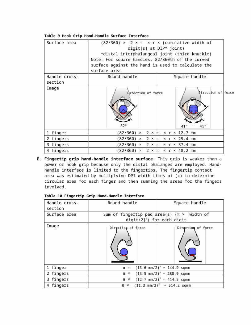
A. Hook grip hand-handle interface surface. A hook grip is less efficient than a power grip because force is only applied by the medial and distal phalanges. A hook grip may be necessary when the handle height opening is not sufficient enough to allow the second knuckle (proximal interphalangeal [PIP] joint) to pass but allows the third knuckle (distal interphalangeal [PIP] joint) to pass. Contact area is limited because only medial and distal phalanges engage the handle. Average third digit PIP joint flexion angles are 80.2° and 83.5° for males and female, respectively, measured from the outside of the grip (Freivalds, 2000). These values were averaged and rounded to 82°.
82°
Direction of force
98° 98°
41° 41°
Direction of force
Direction of force Direction of force
Table 9 Hook Grip Hand-Handle Surface InterfaceSurface area (82/360) × 2 × π × r × (cumulative width of digit[s] at DIP* joint)
*distal interphalangeal joint (third knuckle)Note: For square handles, 82/360th of the curved surface against the hand is used to calculate the surface area.
Handle cross-section Round handle Square handleImage
1 finger (82/360) × 2 × π × r × 12.7 mm2 fingers (82/360) × 2 × π × r × 25.4 mm3 fingers (82/360) × 2 × π × r × 37.4 mm4 fingers (82/360) × 2 × π × r × 48.2 mm
B. Fingertip grip hand-handle interface surface. This grip is weaker than a power or hook grip because only the distal phalanges are employed. Hand-handle interface is limited to the fingertips. The fingertip contact area was estimated by multiplying DPI width times pi (π) to determine circular area for each finger and then summing the areas for the fingers involved.
Table 10 Fingertip Grip Hand-Handle InterfaceHandle cross-section Round handle Square handleSurface area Sum of fingertip pad area(s) (π × [width of digit/2]2) for each digitImage
1 finger π × (13.6 mm/2)2 = 144.9 sqmm2 fingers π × (13.5 mm/2)2 = 288.9 sqmm3 fingers π × (12.7 mm/2)2 = 414.5 sqmm4 fingers π × (11.3 mm/2)2 = 514.2 sqmm
Maximum recommended forces are based on hand-handle interface pressure. These forces may be greater than maximum recommended push, pull, or lifting forces derived using ergonomics assessment tools including those listed in Appendix 2 of SEMI-S8. The lesser value should be used when assessing handles. Optimal handle diameter for most users is 38 mm (Freivalds, 2000), which allows most users to apply the greatest force. For handles that do not have a circular cross section, measure the perimeter of the handle cross section. The optimal perimeter should be approximately the same as the circumference of a 38 mm diameter circle (119 mm).

A
B
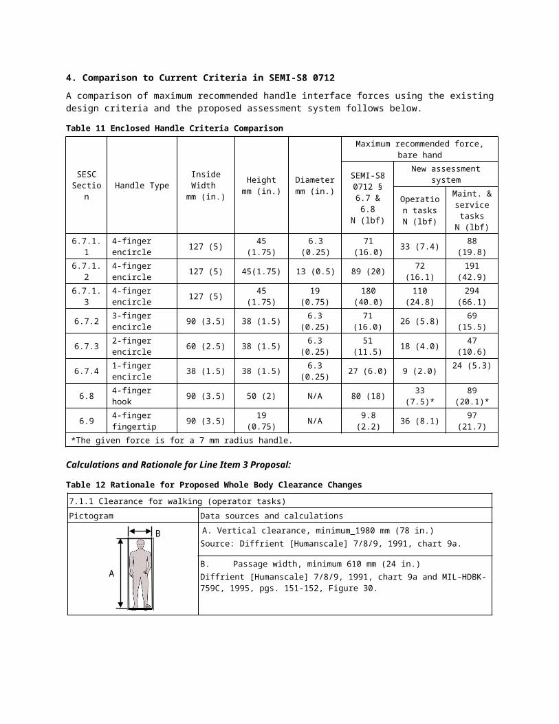
4. Comparison to Current Criteria in SEMI-S8 0712
A comparison of maximum recommended handle interface forces using the existing design criteria and the proposed assessment system follows below.
Table 11 Enclosed Handle Criteria Comparison
SESC Section Handle Type Inside Width
mm (in.)Height
mm (in.)Diametermm (in.)
Maximum recommended force, bare handSEMI-S8 0712 § 6.7
& 6.8N (lbf)
New assessment systemOperation
tasksN (lbf)
Maint. & service tasks
N (lbf)6.7.1.1 4-finger encircle 127 (5) 45 (1.75) 6.3 (0.25) 71 (16.0) 33 (7.4) 88 (19.8)6.7.1.2 4-finger encircle 127 (5) 45(1.75) 13 (0.5) 89 (20) 72 (16.1) 191 (42.9)6.7.1.3 4-finger encircle 127 (5) 45 (1.75) 19 (0.75) 180 (40.0) 110 (24.8) 294 (66.1)6.7.2 3-finger encircle 90 (3.5) 38 (1.5) 6.3 (0.25) 71 (16.0) 26 (5.8) 69 (15.5)6.7.3 2-finger encircle 60 (2.5) 38 (1.5) 6.3 (0.25) 51 (11.5) 18 (4.0) 47 (10.6)6.7.4 1-finger encircle 38 (1.5) 38 (1.5) 6.3 (0.25) 27 (6.0) 9 (2.0) 24 (5.3)6.8 4-finger hook 90 (3.5) 50 (2) N/A 80 (18) 33 (7.5)* 89 (20.1)*6.9 4-finger fingertip 90 (3.5) 19 (0.75) N/A 9.8 (2.2) 36 (8.1) 97 (21.7)
*The given force is for a 7 mm radius handle.
Calculations and Rationale for Line Item 3 Proposal:
Table 12 Rationale for Proposed Whole Body Clearance Changes
7.1.1 Clearance for walking (operator tasks)Pictogram Data sources and calculations
A. Vertical clearance, minimum 1980 mm (78 in.)Source: Diffrient [Humanscale] 7/8/9, 1991, chart 9a.
B. Passage width, minimum 610 mm (24 in.)Diffrient [Humanscale] 7/8/9, 1991, chart 9a and MIL-HDBK-759C, 1995, pgs. 151-152, Figure 30.

C
B
AD
A
B
C
7.1.2 Clearance for walking (maintenance and service activity only)Pictogram Data sources and calculations
A. Vertical clearance, minimum 1900 mm (74.8 in.)Source: EN-ISO 14122-2, Section 4.2.2, Note 1.B. Upper body passage width, minimum 610 mm (24 in.)Source: Diffrient, N., Tilley, A. R., Harman, D., and Henry Dreyfuss Associates “Humanscale 7/8/9: a portfolio of information.” MIT Press, 1991, chart 9a.C. Walking surface width minimum 457 mm (18 in.)Original source: 457 mm (18 in.) (OSHA 29 CFR 1910.23, [c][2])Other dimension sources for comparison:305 mm (12.0 in.) (Damon, 1966, pg. 319).305 mm (12.0 in.) (Van Cott, 1972, pg. 453).305 mm (12.0 in.) (Woodson, 1981, pg. 305)305 mm (12.0 in.) minimum, (Tilley, 1993, pg. 33).305 mm (16 in.) preferred (Tilley, 1993, pg. 33).380 mm (15.0 in.) preferred (MIL-HDBK-759C, 1995, pg. 144).500 mm (19.7 in.) (EN-ISO 14122-2, Section 4.2.2) Note: this dimension is applied to the walkway width at all heights, not just the walking surface.D. Elbow/hip clearance height, maximum height of sloped area 1080 mm (42.5 in.)Source: 1049.99 mm 50th percentile US female elbow height (Harrison, 2002, pg. 77)Adjustment for shoes: add 30 mm.Note: Female data was chosen for this dimension because women have greater hip width than men. 50th percentile US female elbow height was chosen because it’s possible for a 50th percentile female to have 95th percentile hip width (people do not generally match percentiles on more than two dimensions).
7.1.3 Clearance for passing through vertical hatchways (maintenance and service activity only)Pictogram Data sources and calculations
A. Overhead clearance, minimum 1524 mm (60.0 in.)Source: Woodson, W. E. “Human Factors Design Handbook : Information and Guidelines for the Design of Systems, Facilities, Equipment, and Products for Human Use.” McGraw-Hill, 1981, pg. 284.B. Upper body passage width, minimum 610 mm (24 in.)Source: Diffrient [Humanscale] 7/8/9, 1991, chart 9a.C. Height of threshold, maximum 406 in. (16.0 in.)Source: Woodson, W. E. “Human Factors Design Handbook: Information and Guidelines for the Design of Systems, Facilities, Equipment, and Products for Human Use.” McGraw-Hill, 1981, pg. 284.

A
B
B
A
C
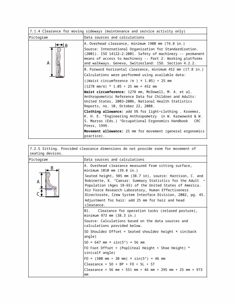
7.1.4 Clearance for moving sideways (maintenance and service activity only)Pictogram Data sources and calculations
A. Overhead clearance, minimum 1900 mm (74.8 in.)Source: International Organization for Standardization. (2001). ISO 14122-2:2001. Safety of machinery -- permanent means of access to machinery -- Part 2: Working platforms and walkways. Geneva, Switzerland: ISO. Section 4.2.2.
B. Forward horizontal clearance, minimum 452 mm (17.8 in.)Calculations were performed using available data:((Waist circumference /π ) × 1.05) + 25 mm(1278 mm/π) * 1.05 + 25 mm = 452 mmWaist circumference: 1278 mm, McDowell, M. A. et al. Anthropometric Reference Data for Children and Adults: United States, 2003–2006, National Health Statistics Reports, no. 10, October 22, 2008.Clothing allowance: add 5% for light clothing . Kroemer, K. H. E. “Engineering Anthropometry” in W. Karwowski & W. S. Marras (Eds.) “Occupational Ergonomics Handbook” CRC Press, 1999.Movement allowance: 25 mm for movement (general ergonomics practice).
7.2.5 Sitting. Provided clearance dimensions do not provide room for movement of seating devices.Pictogram Data sources and calculations
A. Overhead clearance measured from sitting surface, minimum 1010 mm (39.8 in.)Seated height, 985 mm (38.7 in), source: Harrison, C. and Robinette, K. “Caesar: Summary Statistics for the Adult Population (Ages 18-65) of the United States of America.” Air Force Research Laboratory, Human Effectiveness Directorate, Crew System Interface Division, 2002, pg. 45.Adjustment for hair: add 25 mm for hair and head clearance.B1. Clearance for operation tasks (relaxed posture), minimum 973 mm (38.3 in.)Source: Calculations based on the data sources and calculations provided below.SO Shoulder Offset = Seated shoulder height × sin(back angle)SO = 647 mm × sin(5°) = 56 mmFO Foot Offset = (Popliteal Height + Shoe Height) * sin(calf angle)FO = (500 mm + 30 mm) × sin(5°) = 46 mmClearance = SO + BP + FO + SL + STClearance = 56 mm + 551 mm + 46 mm + 295 mm + 25 mm = 973 mmB2. Clearance for maintenance tasks (upright posture), minimum 871 mm (34.3 in.)Source: Calculations based on the data provided below.Clearance = BP + SL + STClearance = 551 mm + 295 mm + 25 mm = 871 mm

Back angle
Calf angle
Shoulder offset
Foot offset
Data used for sections B1 and B2.Symbol Measure Source/Calculation
FL Foot length: 295 mm
Harrison, C. and Robinette, K. “Caesar: Summary Statistics for the Adult Population (Ages 18-65) of the United States of America.” Air Force Research Laboratory, Human Effectiveness Directorate, Crew System Interface Division, 2002.
ST Shoe toe clearance (toe to front of shoe): 25 mm
n/a
BP Buttock popliteal distance: 551 mm
Harrison, 2002 adjusted using data from MIL STD 1472.
SH Shoe height: 30 mm
Pheasant, S. “Bodyspace: Anthropometry, Ergonomics and Design.” Taylor & Francis, 1996.
PH Popliteal height: 500 mm
Harrison, 2002 data ratio scaled using data from MIL STD 1472.
AH Seated acromial (shoulder) height: 647 mm
Harrison, 2002.
C. Seat height, 368 mm (14.5 in.) minimumSeated popliteal (inner knee) height: 338.2 mm Research Institute of Human Engineering for Quality Life. Japanese Body Size Data 2004-2006. Research Institute of Human Engineering for Quality Life, 2008, pg. 411.Adjustment for shoes: Add 30 mm = 368.2 mmC. Seat height, 525 mm (20.7 in.) maximumSeated popliteal (inside of knee) height: 495 mm, Pheasant, S. “Bodyspace: Anthropometry, Ergonomics and Design.” Taylor & Francis, 1996, pg. 188.Adjustment for shoes: Add 30 mm = 525 mm
Please forward a courtesy copy of any comments or negatives against the ballot to Paul Schwab at [email protected].
Respectfully,
Paul Schwab and Ron Macklin,
SEMI-S8 Task Force Co-Leaders
Review and Adjudication InformationTask Force Review (Unofficial) Committee Adjudication (Official)
Group: Ergonomics Task Force NA EHS CommitteeDate: Tuesday, July 8th, 2014 Thursday, July 10th, 2014Time & Time Zone: 3:30 PM to 5:00 PM (U.S. Pacific Time) 9:00 AM to 6:00 PM (U.S. Pacific Time)Location: San Francisco Marriott Marquis Hotel
780 Mission StreetSan Francisco Marriott Marquis Hotel780 Mission Street
City, State/Country: San Francisco, California USA San Francisco, California USALeaders: Paul Schwab (Texas Instruments, Inc.)
Ron Macklin (R. Macklin & Associates)Sean Larsen (Lam Research AG)Chris Evanston (Salus Engineering)Bert Planting (ASML)
Standards Staff: Paul Trio (SEMI NA) [email protected]
Paul Trio (SEMI NA) [email protected]
Details for these meetings are subject to change, and additional review sessions may be scheduled if necessary. Contact the Task Force leaders or Standards staff for confirmation. Telephone and web information will be distributed to interested parties as the meeting date approaches. If you will not be able to attend these meetings in person but would like to participate by telephone/web, please contact Standards staff.

Safety Checklist for SEMI Draft Document #5009CDelayed Line Items Revisions to SEMI S8-0712a, SAFETY GUIDELINES FOR ERGONOMICS ENGINEERING OF SEMICONDUCTOR MANUFACTURING EQUIPMENTDeveloping/Revising Body
Name/Type: Ergonomics Task ForceTechnical Committee: Environmental, Health, and Safety
Region: North America
Leadership
Position Last First AffiliationLeader: Schwab Paul Texas Instruments, Inc.Leader: Macklin Ron R. Macklin & Associates, LLC
Documents, Conflicts, and Consideration
Safety related codes, standards, and practices used in developing the safety guideline, and the manner in which each item was considered by the technical committee.
# and Title Manner of ConsiderationAldien, Y., D. Welcome, S. Rakheja, R. Dong, and P. E. Boileau. "Contact Pressure Distribution at Hand-Handle Interface: Role of Hand Forces and Handle Size." International Journal of Industrial Ergonomics 35, no. 3 (2005): 267-86.
Line item 2, Hand pressure data.
Diffrient, Niels, Alvin R. Tilley, David Harman, and Henry Dreyfuss Associates. Humanscale 4/5/6 : A Portfolio of Information: 4. Human Strength and Safety, 5. Controls and Displays, 6. Designing for People. Cambridge, Mass.: MIT Press, 1981.
Line item 2, Original source for Section 6 handle design criteria.
EN 547-2:2009, Safety of machinery - Human body measurements - Part 2: Principles for determining the dimensions required for access openings, European Committee for Standardization, Vienna, 2009.
Line item 3, Body clearance dimensions.Recommendations within this document were compared to other documents listed in this section. The task force selected criteria that meet the majority of the referenced documents, that are the most conservative, or that are most appropriate for the semiconductor industry.
EN-ISO 14122-1:2001, Safety of machinery : permanent means of access to machinery -- Part 1: Choice of fixed means of access between two levels. European Committee for Standardization, Vienna, 2009.
Line item 3, Body clearance dimensions.Recommendations within this document were compared to other documents listed in this section. The task force selected criteria that meet the majority of the referenced documents, that are the most conservative, or that are most appropriate for the semiconductor industry.
EN-ISO 14122-2:2001, Safety of machinery -- permanent means of access to machinery --Part 2: Working platforms and walkways. European Committee for Standardization, Vienna, 2009.
Line item 3, Body clearance dimensions.Recommendations within this document were compared to other documents listed in this section. The task force selected criteria that meet the majority of the referenced documents, that are the most conservative, or that are most appropriate for the semiconductor industry.
EN-ISO 14738:2002, Safety of machinery –Anthropometric requirements for the design of workstations at machinery.
Line item 3, Body clearance dimensions.Recommendations within this document were compared to other documents listed in this section. The task force selected criteria that meet the majority of the referenced documents, that are the most conservative, or that are most appropriate for the semiconductor industry.
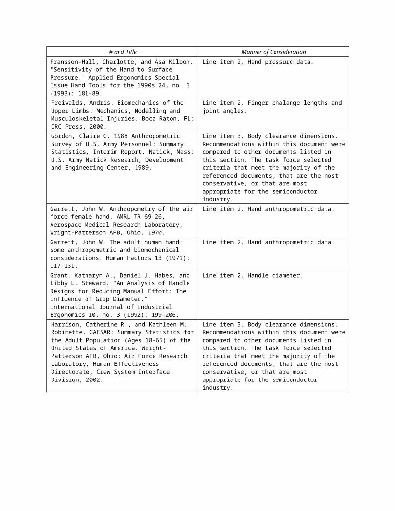
# and Title Manner of ConsiderationFransson-Hall, Charlotte, and Åsa Kilbom. "Sensitivity of the Hand to Surface Pressure." Applied Ergonomics Special Issue Hand Tools for the 1990s 24, no. 3 (1993): 181-89.
Line item 2, Hand pressure data.
Freivalds, Andris. Biomechanics of the Upper Limbs: Mechanics, Modelling and Musculoskeletal Injuries. Boca Raton, FL: CRC Press, 2000.
Line item 2, Finger phalange lengths and joint angles.
Gordon, Claire C. 1988 Anthropometric Survey of U.S. Army Personnel: Summary Statistics, Interim Report. Natick, Mass: U.S. Army Natick Research, Development and Engineering Center, 1989.
Line item 3, Body clearance dimensions. Recommendations within this document were compared to other documents listed in this section. The task force selected criteria that meet the majority of the referenced documents, that are the most conservative, or that are most appropriate for the semiconductor industry.
Garrett, John W. Anthropometry of the air force female hand, AMRL-TR-69-26, Aerospace Medical Research Laboratory, Wright-Patterson AFB, Ohio. 1970.
Line item 2, Hand anthropometric data.
Garrett, John W. The adult human hand: some anthropometric and biomechanical considerations. Human Factors 13 (1971): 117-131.
Line item 2, Hand anthropometric data.
Grant, Katharyn A., Daniel J. Habes, and Libby L. Steward. "An Analysis of Handle Designs for Reducing Manual Effort: The Influence of Grip Diameter." International Journal of Industrial Ergonomics 10, no. 3 (1992): 199-206.
Line item 2, Handle diameter.
Harrison, Catherine R., and Kathleen M. Robinette. CAESAR: Summary Statistics for the Adult Population (Ages 18-65) of the United States of America. Wright-Patterson AFB, Ohio: Air Force Research Laboratory, Human Effectiveness Directorate, Crew System Interface Division, 2002.
Line item 3, Body clearance dimensions. Recommendations within this document were compared to other documents listed in this section. The task force selected criteria that meet the majority of the referenced documents, that are the most conservative, or that are most appropriate for the semiconductor industry.
Hertzberg, H., I. Emanuel, and M. Alexander, The Anthropometry of Working Positions. 1. A Preliminary Study, WADC Technical Report 54-520. Wright-Patterson Air Force Base, Ohio, 1956.
Line item 3, Body clearance dimensions.Recommendations within this document were compared to other documents listed in this section. The task force selected criteria that meet the majority of the referenced documents, that are the most conservative, or that are most appropriate for the semiconductor industry.
ISO 14738: Safety of Machinery - Anthropometric Requirements for the Design of Workstations at Machinery. International Standards, 14738, Geneva: International Organization for Standardization, 2002.
Line item 3, Body clearance dimensions.Recommendations within this document were compared to other documents listed in this section. The task force selected criteria that meet the majority of the referenced documents, that are the most conservative, or that are most appropriate for the semiconductor industry.
Japanese Body Size Data, 2004-2006. Research Institute of Human Engineering for Quality of Life: Osaka, Japan, 2008.
Line item 3, Body clearance dimensions.Minimum chair height.
Johansson, Lena, Anders Kjellberg, Ãsa Kilbom, and Goran M. Hagg. "Perception of Surface Pressure Applied to the Hand." Ergonomics 42, no. 10 (1999): 1274-82.
Line item 2, Hand pressure data.
Human Hand Dimension for Ergonomic Design 2010. Research Institute of Human Engineering for Quality Life: Osaka, Japan, 2010.
Line item 2, Hand anthropometric data.
McDowell, M. A. et al. Anthropometric Reference Data for Children and Adults: United States, 2003–2006, National Health Statistics Reports, no. 10, October 22, 2008.
Line item 3, Body clearance dimensions.Abdominal circumference measurements.
MIL-HDBK-759: Handbook for Human Engineering Design Guidelines. Washington, D.C: Department of Defense.
Line item 2, Handle design criteria.
SEMI S2-0712 Environmental Health and Safety Guideline for Semiconductor Manufacturing Equipment.
All line items. Reviewed to avoid direct conflicts.
SEMI S8-0712 Safety Guidelines for Ergonomics Engineering of Semiconductor Manufacturing Equipment.
All line items. Base document for changes.

Info
rmat
iona
l (B
lue)
Bal
lot
DRAFTDocument Number: 5009C
Date: 5/8/23
This is a Draft Document of the SEMI International Standards program. No material on this page is to be construed as an official or adopted Standard or Safety Guideline. Permission is granted to reproduce and/or distribute this document, in whole or in part, only within the scope of SEMI International Standards committee (document development) activity. All other reproduction and/or distribution without the prior written consent of SEMI is prohibited.
Page 1 Doc. jn l SEMI
Semiconductor Equipment and Materials International3081 Zanker RoadSan Jose, CA 95134-2127Phone: 408.943.6900, Fax: 408.943.7943
# and Title Manner of ConsiderationSeo, Na Jin, and Thomas J. Armstrong. "Investigation of Grip Force, Normal Force, Contact Area, Hand Size, and Handle Size for Cylindrical Handles." Human Factors: The Journal of the Human Factors and Ergonomics Society 50, no. 5 (2008): 734-44.
Line item 2, Handle normal force data.
United States Occupational Safety & Health Administration. General Industry : OSHA Safety and Health Standards (29 CFR 1910). Washington, D.C. U.S. Dept. of Labor, Occupational Safety and Health Administration, 1983.
Line item 3, Body clearance dimensions.Walking path clearance.
VanCott, Harold P., and Robert G. Kinkade, Ed., Human Engineering Guide to Equipment Design, U.S. Department of Defense. Washington, D.C.: U.S. Government Printing Office, 1972.
Line item 3, Body clearance dimensions.Recommendations within this document were compared to other documents listed in this section. The task force selected criteria that meet the majority of the referenced documents, that are the most conservative, or that are most appropriate for the semiconductor industry.
Known inconsistencies between the safety guideline and any other safety related codes, standards, and practices cited in the safety guideline
# and Title Inconsistency with This Safety Guideline # and Title Inconsistency with This Safety GuidelineNone known None known
Other conflicts with known codes, standards, and practices or with commonly accepted safety and health principles to the extent practical
# and Title Nature of Conflict with This Safety GuidelineNone known None known
Participants and ContributorsName, Last Name, First Affiliation
Austin Lindy Salus EngineeringBarsky Joe TUV RheinlandBirrell Ron TUVSUD AmericaBogner Mark TUVSUD AmericaBraun Stephan TUV ReinlandBreder Paul Estec SolutionsBrody Steve Product ESH ConsultingCrane Lauren KLA-TencorCrockett Alan KLA-TencorD'Agostino Mark VarianErgete Nigusu Intertek, Global Semiconductor Safety Services, GS3Evanston Chris Salus EngineeringFaust Bruce TUV AmericaFessler Mark TELFrankfurth Mark CymerFunk Rowland Salus EngineeringGiles Andrew Estec SolutionsGreen Paul UltratechGreenburg Cliff NikonHamilton Jeff TELHarralson Mark IntelHayford James AMAT/SemitoolHsu Peter AixtronHughes Stanley Lam Research

Lette
r (Ye
llow
) Bal
lot DRAFT
Document Number: 5009CDate: 5/8/23
This is a Draft Document of the SEMI International Standards program. No material on this page is to be construed as an official or adopted Standard or Safety Guideline. Permission is granted to reproduce and/or distribute this document, in whole or in part, only within the scope of SEMI International Standards committee (document development) activity. All other reproduction and/or distribution without the prior written consent of SEMI is prohibited.
Page 1 Doc. jn l SEMI
Semiconductor Equipment and Materials International3081 Zanker RoadSan Jose, CA 95134-2127Phone: 408.943.6900, Fax: 408.943.7943
Name, Last Name, First AffiliationIbuka Shigehito HoribaIllerhaus Chris CI Industrial Safety Consulting, LLCJones Matt EmpiricalKapur Ken KLA-TencorKarl Ed Applied MaterialsKelly Paul Estec SolutionsKiley Andrew VarianKrauss Mark System Development-ESHKrauss Josh EHS2Krov Alan TELKryska Paul NovellusKuwatani Ken TUV-SUDLarson Sean LAM AGLayman Curt SeagateLeboults Kyle XactixMacklin Ron Ron Macklin AssociatesMarshall Les Global 450 ConsortiumMashiro Supika TELMcDaid Raymond LAMMcGreevey Mark DNS ElectronicsMills Ken Estec SolutionsNesbitt Abraham ESTECOswalt James MattsonPetry William IBM CorporationPlanting Bert ASMLRai Sunny IntertekRoberge Steven Axcelis Technologies, Inc.Sackllah Michael IntelSawyer Debbie Glacier Export Services, LLCSchmitt Jeff IBMSchwab Paul Texas Instruments, Inc.Shristi Kharel KLA-TencorSklar Eric Safety GuruSleiman Samir Brooks AutomationTan Conrad Lewis BassWerner Stephen Intel CorporationWong Carl AMATYakimow Byron Cymer
The content requirements of this checklist are documented in § 14.2 of the Regulations Governing SEMI Standards Committees.
Info
rmat
iona
l (B
lue)
Bal
lot
DRAFTDocument Number: 5009C
Date: 5/8/23
SEMI Draft Document #5009CLine Item Revisions to SEMI S8-0712a, SAFETY GUIDELINES FOR ERGONOMICS ENGINEERING OF SEMICONDUCTOR MANUFACTURING EQUIPMENT (Effective July, 2015)Delayed Revisions on Multiple TopicsNOTICE: Per ¶ 3.4.3.3.1 of the SEMI Standards Procedure Guide, the purpose, scope, limitations, and terminology sections of SEMI S8 are provided below.
The line item changes proposed by this ballot begin on page 9.
1 Purpose1.1 These guidelines provide ergonomics design principles and considerations for semiconductor manufacturing equipment.
1.2 The purpose of these guidelines is to promote compatibility between the user and the equipment in the manufacturing environment. The following general principles are integral to the ergonomics design and evaluation of equipment:
1.2.1 The equipment should be designed to optimize safety by distributing tasks. Tasks should be distributed among hardware, software, and users to make the best use of their respective capabilities and to minimize limitations and hazards. Appropriate distribution of tasks will also optimize performance.
1.2.2 Equipment should be designed to minimize potential for errors and mishaps, by conforming to users’ expectations.
1.2.3 The equipment design should reduce fatigue and injury by fitting the equipment to the expected body size, strength, and range of motion characteristics of the user population. Such design will also facilitate task performance.
2 Scope2.1 The guidelines address safety aspects of ergonomics engineering in the design of semiconductor manufacturing equipment. It should be noted that in order to ensure comprehensive coverage of potential safety hazards, some guidelines also address general design goals for effective human-machine performance. The guidelines apply to the design, operation, maintenance, and service of semiconductor manufacturing equipment, as well as, to a limited extent, equipment installation (see ¶ 7.3 ).
NOTICE: SEMI Standards and Safety Guidelines do not purport to address all safety issues associated with their use. It is the responsibility of the users of the Documents to establish appropriate safety and health practices, and determine the applicability of regulatory or other limitations prior to use.
3 Limitations3.1 International, national, and local standards, codes, and regulations must be consulted to ensure that equipment meets regulatory requirements.
3.2 Human factors data compiled in references and specifications are influenced by the population from which they were drawn and the reason they were collected. Human factors design criteria are sometimes based on studies using few subjects or are context-specific. Ergonomics experts should be consulted where data development or interpretation is required.
3.3 The equipment design should incorporate reasonable accommodations for users with special needs, such as left-handedness and color blindness. Where feasible the design should also accommodate users with hearing or vision impairments and/or physical disabilities. It should be understood that although designing for the target user population will accommodate some users with special needs, these guidelines cannot anticipate and fully accommodate all such users.
This is a Draft Document of the SEMI International Standards program. No material on this page is to be construed as an official or adopted Standard or Safety Guideline. Permission is granted to reproduce and/or distribute this document, in whole or in part, only within the scope of SEMI International Standards committee (document development) activity. All other reproduction and/or distribution without the prior written consent of SEMI is prohibited.
Page 1 Doc. jn l SEMI
Semiconductor Equipment and Materials International3081 Zanker RoadSan Jose, CA 95134-2127Phone: 408.943.6900, Fax: 408.943.7943

Info
rmat
iona
l (B
lue)
Bal
lot
DRAFTDocument Number: jn l
Date: 5/8/23
3.4 Existing models and subsystems that meet previous versions of SEMI S8 should continue to meet the guidelines of SEMI S8 in force at the time of design. Models with redesigns that significantly affect the ergonomic design of the equipment should include conformance to the latest version of SEMI S8 for the redesign.
1: Conformance with this document is believed to be a suitable substitute for conformance with its predecessors.
3.5 Conformance with the guidelines in Appendix 1 (SESC) constitutes conformance with SEMI S8.
4 Referenced Standards and Documents4.1 SEMI Standards and Safety Guidelines
SEMI E95 — Specification for Human Interface for Semiconductor Manufacturing Equipment
SEMI S1 — Safety Guideline for Equipment Safety Labels
SEMI S2 — Environmental, Health, and Safety Guidelines for Semiconductor Manufacturing Equipment
SEMI S10 — Safety Guideline for Risk Assessment and Risk Evaluation Process
4.2 CEN/CENELEC Standards1
4.2.1 European Norm (EN) standards are listed herein for application to semiconductor manufacturing equipment to be used in the European Union (EU). As EN standards are intended for use with a broad range of industrial and consumer products, conflicts with SEMI safety guidelines are likely. Additionally, provisional EN (prEN) standards are subject to revision prior to adoption.
EN 894-2 — Safety/Ergonomics for Displays
EN 894-3 — Safety/Ergonomics for Control Actuators
EN 60204-1 — Safety of Machinery – Electrical Equipment of Machines, Part 1 – Specification for General Requirements
4.3 Military Standard2
MIL-STD-1472 — Human Engineering Design Criteria for Military Systems, Equipment, and Facilities
4.4 NFPA Standard3
NFPA 79 — Electrical Standard for Industrial Machinery
4.5 ISO Standard4
ISO 9241 — Ergonomic Requirements for Office Work with Visual Display Terminals
4.6 Other Standards and Documents
Humanscale, The MIT Press, Massachusetts Institute of Technology, Cambridge, MA 02142, 1974
ANSI/IES RP75 — Practice for Industrial Lighting
Waters, Thomas, et al., Application Manual for the Revised NIOSH Lifting Equation, U.S. Department of Health and Human Services (NIOSH), Cincinnati, OH, 1994.
A. Mital, A.S. Nicholson, M.M. Ayoub: A Guide to Manual Materials Handling, Taylor and Francis, London, 1993.
NOTICE: Unless otherwise indicated, all documents cited shall be the latest published versions.
1 European committee for standardization (CEN)/European Committee for Electrotechnical Standardization (CENELEC), Central Secretariat: rue de Stassart 35, B-1050 Brussels, Belgium. http:// www.cenelac.org 2 United States Military Standards, Available through the Naval Publications and Forms Center, 5801 Tabor Avenue, Philadelphia, PA 19120-5099, USA. Telephone: 215.697.33213 National Fire Protection Association, 1 Batterymarch Park, Quincy, MA 02269, USA. http:// www.nfpa.org 4 International Organization for Standardization, ISO Central Secretariat, 1, rue de Varembé, Case postale 56, CH-1211 Geneva 20, Switzerland. Telephone: 41.22.749.01.11; Fax: 41.22.733.34.30; http:// www.iso.ch 5 American National Standards Institute, 25 West 43rd Street, New York, NY 10036, USA; Telephone: 212.642.4900, Fax: 212.398.0023, http://www.ansi.org
This is a Draft Document of the SEMI International Standards program. No material on this page is to be construed as an official or adopted Standard or Safety Guideline. Permission is granted to reproduce and/or distribute this document, in whole or in part, only within the scope of SEMI International Standards committee (document development) activity. All other reproduction and/or distribution without the prior written consent of SEMI is prohibited.
Page 2 Doc. jn l SEMI
Semiconductor Equipment and Materials International3081 Zanker RoadSan Jose, CA 95134-2127Phone: 408.943.6900, Fax: 408.943.7943

Info
rmat
iona
l (B
lue)
Bal
lot
DRAFTDocument Number: jn l
Date: 5/8/23
5 Terminology5.1 Abbreviations and Acronyms
5.1.1 MAWL — maximum acceptable weight of lift
5.1.2 MMH — manual material handling
5.1.3 SESC — supplier ergonomics success criteria (see Appendix 1)
5.2 Definitions
5.2.1 administrative controls — administrative controls modify the way in which a job is performed without involving equipment design. They are non-engineering controls which include: job rotation, job enlargement, work-rest scheduling, micro-breaks, and stretching exercises. Engineering controls are preferred over administrative controls.
5.2.2 anthropometric considerations — design considerations based upon anthropometric (e.g., size and strength) limitations of user personnel.
5.2.3 anthropometry — description of the physical measurement of humans (e.g., size and strength).
5.2.4 cognitive — relating to human information processing, perception, and attention.
5.2.5 critical controls and displays — controls and displays which prevent the equipment from entering, or indicate that equipment is entering an unsafe condition in which hazards to personnel or damage to equipment may occur. Emergency Off (EMO) switches, interlock defeat indicators, and malfunction alarms are examples of critical controls and displays.
5.2.6 cumulative trauma disorder — a disorder which results from the accumulation of stresses (e.g., forces, repetitive movements, etc.) to a body part over a period of time.
5.2.7 duration — the length of time of a cycle or the entire task, which represents the time of exposure to single or multiple risk factors.
5.2.8 emergency off (EMO) — a control circuit which, when activated, places the equipment into a safe shutdown condition.
5.2.9 engineering control — a method to eliminate or mitigate a hazard through equipment design.
5.2.10 ergonomic-related hazard — an equipment or workplace condition that creates stress to the user that contributes to the risk of developing either an acute injury or a cumulative trauma disorder.
5.2.11 ergonomic issues — those issues dealing with the user’s physical and cognitive needs, capabilities, and human performance limitations in relation to the design of machines, tasks, and other features of the human’s working environment.
5.2.12 ergonomics — the study of human mental and physical capability in relation to the working environment and the equipment operated by the worker.
5.2.13 excessive reach — a reach which may result in biomechanical or other stress to the user.
5.2.14 extended reach — a reach which requires either stretching, stooping, crouching, bending forward at the waist greater than 20°, or shoulder flexion or abduction greater than 45°.
5.2.15 force — the mechanical effort to accomplish a specific movement or exertion. These include: static exertions, which produce no motion but have significant duration; dynamic exertions, which are motions including lifting, pushing, pulling; and contact stress, which is localized pressure exerted against the skin by an external force.
5.2.16 frequency — how often a task is performed over time.
5.2.17 frequently used — used in processing or job cycle at least once every hour. Multiple tool operation by a single operator should be considered.
5.2.18 human error — errors which include: failure to perform a required function; performing a function that has an undesirable consequence; failure to recognize and correct a hazardous condition; or inadequate or incorrect response to a contingency.
This is a Draft Document of the SEMI International Standards program. No material on this page is to be construed as an official or adopted Standard or Safety Guideline. Permission is granted to reproduce and/or distribute this document, in whole or in part, only within the scope of SEMI International Standards committee (document development) activity. All other reproduction and/or distribution without the prior written consent of SEMI is prohibited.
Page 3 Doc. jn l SEMI
Semiconductor Equipment and Materials International3081 Zanker RoadSan Jose, CA 95134-2127Phone: 408.943.6900, Fax: 408.943.7943

Info
rmat
iona
l (B
lue)
Bal
lot
DRAFTDocument Number: jn l
Date: 5/8/23
5.2.19 inadvertent actuation — accidental or unintentional activation or deactivation of a control.
5.2.20 infrequently used — used in processing or job cycle less frequently than once every hour. Multiple tool operation by a single operator should be considered.
5.2.21 installation — the activities performed after the equipment is received at a user site through preparation for initial service, including transportation, lifting, uncrating, placement, leveling, and facilities fit up.
5.2.22 lateral pinch — grip in which the object is held between the thumb and the side of the index finger (often referred to as key grip).
5.2.23 maintenance — planned or unplanned activities intended to keep equipment in good working order.
5.2.24 mock up — a full size physical model of the equipment, generally made of relatively inexpensive materials, used for human factors evaluation.
5.2.25 neutral posture — the position of the human body in which the joints are least stressed. Generally, the body in its neutral position is standing erect with the eyes looking forward, and the arms hanging by the sides.
5.2.26 non-neutral (awkward) postures — the position of a joint(s) away from its neutral, or least stressed, posture.
5.2.27 normal line of sight — the line extending from the eyes, perpendicular to the intraocular line and 15° below the horizontal position of the eye.
5.2.28 operation — consists of functions by which the operator causes the equipment to perform its intended purpose; these may include loading product and setting or manipulating external controls.
5.2.29 operator — a user that interacts with the equipment only to the degree necessary for the equipment to perform its intended function.
5.2.30 override — to take precedence over the current control system state.
5.2.31 palmar pinch — grip where the fingers press against the palm of the hand, with the object held between the fingers and the palm. Thumb is not used (e.g., picking up a sheet of plywood).
5.2.32 personal protective equipment (PPE) — equipment and clothing worn to reduce potential for personal injury from hazards associated with the task to be performed (e.g., chemical gloves, respirators, safety glasses, etc.). In the context of this document, cleanroom attire (e.g., gloves, smocks, booties, hoods) is not considered personal protective equipment.
5.2.33 power grip — a grip in which the fingers and thumb wrap entirely around the handle such that the thumb contacts or overlaps the index finger.
5.2.34 postural stress — stress occurring when a body position places undue load on the muscles, tendons, nerves, and blood vessels, or produces pressure on a joint.
5.2.35 primary viewing area — the 30° cone around the normal line of site (15° above, below, and to either side of the line of sight).
5.2.36 problem tasks — tasks which have been defined as presenting ergonomically incorrect conditions that are likely to cause biomechanical stresses or injury to personnel, misoperation, or damage to equipment or the product.
5.2.37 risk factors — those elements of the design which allow an increased potential for injury/illness to personnel, or for damage to equipment, environment, or product.
5.2.38 semiconductor manufacturing equipment — equipment used in the design, development, manufacture, assembly, measurement and test of semiconductors, and associated semiconductor support processes.
5.2.39 service — unplanned activities intended to return equipment, which has failed, to good working order.
5.2.40 static posture — a fixed position, with minimal movement of the particular body parts.
5.2.41 stooping — bending the head and shoulders, or the general body, forward and downward from an erect position.
5.2.42 task — a group of related job elements performed within the work cycle and directed toward a specific objective.
This is a Draft Document of the SEMI International Standards program. No material on this page is to be construed as an official or adopted Standard or Safety Guideline. Permission is granted to reproduce and/or distribute this document, in whole or in part, only within the scope of SEMI International Standards committee (document development) activity. All other reproduction and/or distribution without the prior written consent of SEMI is prohibited.
Page 4 Doc. jn l SEMI
Semiconductor Equipment and Materials International3081 Zanker RoadSan Jose, CA 95134-2127Phone: 408.943.6900, Fax: 408.943.7943

Info
rmat
iona
l (B
lue)
Bal
lot
DRAFTDocument Number: jn l
Date: 5/8/23
5.2.43 task analysis — an analytical process employed to determine the specific actions required of the user when operating, maintaining, or servicing equipment, or doing work on single or multiple tools. Within each task, steps are described in terms of the perception, decision-making, memory storage, posture, and biomechanical requirements, as well as the expected errors.
5.2.44 tip pinch — grip in which the object is held between the tips of the thumb and index finger.
5.2.45 user — person interacting with the equipment. Users may include operators, maintainers, service personnel, and others.
5.2.46 user population — a specific cross section of persons that may reasonably be expected to interact with the equipment to perform operation, maintenance, or service tasks.
5.2.47 validation testing — testing to confirm effectiveness of design. An item’s “effectiveness” is viewed in terms of its functional design, specific to SEMI S8.
5.2.48 WIP nest — a storage structure for work in process (WIP).
5.2.49 work environment — the location where semiconductor devices and associated support processes are designed, developed, manufactured, assembled, measured, and tested.
5.2.50 workplace layout — the physical arrangement of equipment in the facility.
5.2.51 workspace — the available area where the user is expected to operate, maintain, and service the equipment.
5.2.52 workstation — the location where equipment controls and displays are found or the location of loading/unloading of material.
5.2.53 work surface — a (typically horizontal) surface provided for the location of input devices, handwriting, assembly work, etc. that is part of a seated or standing workstation.
6 General Guidelines[This section has been omitted from the ballot in the interest of brevity. If you need a copy of this section in order to vote, please contact SEMI Staff. ]
7 Documentation7.1 The supplier should provide an evaluation of the equipment to SEMI S8 using Appendix 1, “Supplier Ergonomic Success Criteria” for measurable criteria. The evaluation should include a determination of the level of risk associated with non-conformance items. Evaluation of risk should be compatible with the SEMI S10 severity categories; catastrophic, severe, moderate, and minor.
7.1.1 For each item in Appendix 1 which does not meet the criteria, the evaluation report should include the measured actual dimensions, and state any supporting rationale for non-compliance. Supporting rationale may include test data or documented engineering judgment.
EXCEPTION: For § 1, the manual material handling analysis, the evaluation report should provide documented calculations regardless of the outcome of the analysis.
7.1.2 The evaluation report should also include the following information: manufacturer’s model number, serial number of unit evaluated, date the equipment was evaluated, a list of all tasks which were evaluated as part of the analysis and the name of the person performing the evaluation.
7.2 Supplier provided documentation should include administrative controls intended by the supplier to mitigate ergonomic risks.
7.3 Supplier provided documentation should illustrate any installation requirement necessary to meet SEMI S8 guidelines (e.g., Diagram should show clearance area required for opening hinged panels, operator working area, allowable range of vertical foot adjustment to keep ergonomic measurements within SESC acceptable limits, etc.).
7.4 The evaluation should specify an installation reference point for each independently adjustable section of the equipment for vertical measures. If there is a supplier recommended installation height, the reference for the evaluation should be the same. This installation height should be included in the supplier’s installation documentation.
This is a Draft Document of the SEMI International Standards program. No material on this page is to be construed as an official or adopted Standard or Safety Guideline. Permission is granted to reproduce and/or distribute this document, in whole or in part, only within the scope of SEMI International Standards committee (document development) activity. All other reproduction and/or distribution without the prior written consent of SEMI is prohibited.
Page 5 Doc. jn l SEMI
Semiconductor Equipment and Materials International3081 Zanker RoadSan Jose, CA 95134-2127Phone: 408.943.6900, Fax: 408.943.7943

Info
rmat
iona
l (B
lue)
Bal
lot
DRAFTDocument Number: jn l
Date: 5/8/23
2: Installation documentation may include installation manuals and other information provided by supplier addressing installation concerns.
8 Related Documents8.1 SEMI Standards and Safety Guidelines
SEMI S13 — Safety Guidelines for Operation and Maintenance Manuals Used with Semiconductor Manufacturing Equipment
8.2 ANSI Standards
ANSI Z535.4 — Product Safety Signs and Labels
ANSI/HFES 100 — Human Factors Engineering of Computer Workstations; Human Factors and Ergonomics Society, 2007.
8.3 CEN/CENELEC Standards6
EN 614-1 — Safety of Machinery – Ergonomic Design Principles, Part 1 – Terminology and General Principles
EN 894-1 — Safety/Ergonomics for Operator Interaction
EN 894-2:1997 — Safety of Machinery: Ergonomics Requirements for the Design of Displays and Control Actuators, Part 2: Displays
EN 50099-2 — Safety/Marking Principles
8.4 ISO Standards7
EN ISO 7250 — Basic Human Body Measurements for Technological Design
EN ISO 14738 — Safety of Machinery, Anthropometric Requirements for the Design of Workstations at Machinery
8.5 JIS Standards8
JIS Z 8513 — Ergonomics – Office Work with Visual Display Terminals (VDTs) – Visual Display Requirements (Amendment 1)
8.6 NIOSH Documents9
NIOSH Publication No. 81-122 — Work Practices Guide for Manual Lifting, National Institute for Occupational Safety and Health, 1981.
Revised NIOSH Equation, Ergonomics, Vol. 36, No. 7, 1993.
8.7 SAE Document10
SAE J833 — Human Physical Dimensions
8.8 SEMATECH Documents11
Preventing User-Hostile Interfaces in IC-Fab Equipment — Ergonomic Approaches for Preventing Ten Frequent Interface Problems, Miller, Dwight P. and Whitehurst, Hugh, SEMATECH Technology Transfer #92091299NA-ENG, Nov. 1992.
SEMATECH SCC User interface Style Guide, 1.0. 92061179A-ENG, August 21, 1992.
6 European Committee for Standardization (CEN)/European Committee for Electrotechnical Standardization (CENELEC), Central Secretariat, rue de Stassart 35, B-1050 Brussels, Belgium; http:// www.cenelec.com 7 International Organization for Standardization, ISO Central Secretariat, 1 rue de Varembé, Case postale 56, CH-1211 Geneva 20, Switzerland; Telephone: 41.22.749.01.11, Fax: 41.22.733.34.30, http://www.iso.ch8 Japanese Standards Association, 4-1-24 Akasaka, Minato-ku, Tokyo 107-8440, Japan; Telephone: 81.3.3583.8005, Fax: 81.3.3586.2014, http://www.jsa.or.jp9 National Institute for Occupational Safety and Health, Technical Information Branch, 4676 Columbia Pkwy, Cincinnati, OH 45226, USA; http:// www.niosh.com.my 10 Society of Automotive Engineers, 400 Commonwealth Drive, Warrendale, PA 15096-0001, USA; Telephone: 724.776.4970, Fax: 724.776.0790, http://www.sae.org11 SEMATECH, 257 Fuller Road, Suite 2200, Albany, NY 12203, USA; Telephone: 518.649.1000, http://www.sematech.org
This is a Draft Document of the SEMI International Standards program. No material on this page is to be construed as an official or adopted Standard or Safety Guideline. Permission is granted to reproduce and/or distribute this document, in whole or in part, only within the scope of SEMI International Standards committee (document development) activity. All other reproduction and/or distribution without the prior written consent of SEMI is prohibited.
Page 6 Doc. jn l SEMI
Semiconductor Equipment and Materials International3081 Zanker RoadSan Jose, CA 95134-2127Phone: 408.943.6900, Fax: 408.943.7943

Info
rmat
iona
l (B
lue)
Bal
lot
DRAFTDocument Number: jn l
Date: 5/8/23
8.9 Other Documents
8.9.1 Bailey, Robert W. “Human Performance Engineering.” Prentice Hall, 1989.
8.9.2 Eastman Kodak Company “Ergonomic Design for People at Work, Vols. 1 and 2.” Van Nostrand-Reinhold, 1983.
8.9.3 Grandjean, E., Fitting the Task to the Man: A Textbook of Occupational Ergonomics (4th Ed.), Taylor & Francis, 1988.
8.9.4 Grether W.F. and Baker C.A., 1972, Visual Presentation of Information in Van Cott and Kincade “Human Engineering to Equipment Design.” Washington DC, US Government Printing Office.
8.9.5 Konz, S. “Work Design: Industrial Ergonomics.” (3rd Ed), Publishing Horizons, 1990.
8.9.6 Kroemer, K.H.E. “Engineering Anthropometry.” Occupational Ergonomics Handbook, eds. W. Karwowski & W.S. Marras, CRC Press, Boca Raton, 1999.
8.9.7 Pheasant, Stephen, Bodyspace “Anthropometry, Ergonomics and Design.” Taylor & Francis, 1988.
8.9.8 Salvendy, Gavriel (ed.) “Handbook of Human Factors.” Wiley, 1987.
8.9.9 Sanders, Mark S. and McCormick, Ernest “Human Factors in Engineering and Design.” (7th Ed), McGraw-Hill Book Company, 1993.
8.9.10 Snook, Stover and V. Ciriello “The Design of Manual Handling Tasks — Revised Tables of Maximum Acceptable Weights and Forces.” Ergonomics, Vol. 34, No. 9, 1991.
8.9.11 VanCott, Harold P. and Kinkade, Robert (eds.) “Human Engineering Guide to Equipment Design.” U. S. Government Printing Office, 1972.
APPENDIX 1SUPPLIER ERGONOMIC SUCCESS CRITERIA (SESC)NOTICE: The material in this Appendix is an official part of SEMI S8 and was approved by full letter ballot procedures on November 21, 2006.
A1-1 IntroductionA1-1.1 Pictograms and text within the pictogram cells are provided for illustrative purposes only and are not normative. Also, the pictograms are not intended to depict every possible application of the guidelines.
Supplier Ergonomic Success Criteria Checklist[The SEMI S8 Appendix 1 Checklist has been omitted from the ballot in the interest of brevity. If you need a copy of Appendix 1 in order to vote, please contact SEMI Staff.]
This is a Draft Document of the SEMI International Standards program. No material on this page is to be construed as an official or adopted Standard or Safety Guideline. Permission is granted to reproduce and/or distribute this document, in whole or in part, only within the scope of SEMI International Standards committee (document development) activity. All other reproduction and/or distribution without the prior written consent of SEMI is prohibited.
Page 7 Doc. jn l SEMI
Semiconductor Equipment and Materials International3081 Zanker RoadSan Jose, CA 95134-2127Phone: 408.943.6900, Fax: 408.943.7943
Info
rmat
iona
l (B
lue)
Bal
lot
DRAFTDocument Number: jn l
Date: 5/8/23
APPENDIX 2LIFTING, STRENGTH, AND MATERIALS HANDLING
RELATED INFORMATION 1 ANTHROPOMETRIC RESOURCE DATA
RELATED INFORMATION 2 WORKSTATION DESIGN
RELATED INFORMATION 3 DESIGN FOR MAINTAINABILITY AND SERVICEABILITY
RELATED INFORMATION 4 HAZARD ALERTS, LABELS, AND ALARMS
RELATED INFORMATION 5 CONTROLS AND DISPLAYS
RELATED INFORMATION 6 USER COMPUTER INTERFACE[The SEMI S8 Appendix 2 and Related Information sections 1 through 6 have been omitted from the ballot in the interest of brevity. If you need a copy of these sections in order to vote, please contact SEMI Staff.]
This is a Draft Document of the SEMI International Standards program. No material on this page is to be construed as an official or adopted Standard or Safety Guideline. Permission is granted to reproduce and/or distribute this document, in whole or in part, only within the scope of SEMI International Standards committee (document development) activity. All other reproduction and/or distribution without the prior written consent of SEMI is prohibited.
Page 8 Doc. jn l SEMI
Semiconductor Equipment and Materials International3081 Zanker RoadSan Jose, CA 95134-2127Phone: 408.943.6900, Fax: 408.943.7943

Info
rmat
iona
l (B
lue)
Bal
lot
DRAFTDocument Number: jn l
Date: 5/8/23
Line Item 1DELAYED REVISIONS X (Effective July 2015)Ergonomic Clearances ClarificationNOTICE: This Delayed Revisions Section contains material that has been balloted and approved by the SEMI Environmental, Health and Safety Committee, but is not immediately effective. The provisions of this material are not an authoritative part of the document until their effective date. The main body of SEMI S08 Appendix 1 remains the authoritative version. Some or all of the provisions of revisions not yet in effect may optionally be applied prior to the effective date, providing they do not conflict with portions of the authoritative version other than those that are to be revised or replaced as part of the deferred revision, and are labeled accordingly.
NOTICE: Unless otherwise noted, all material to be added shall be underlined, and all material to be deleted shall be struck through.
DX-1 Revisions to § 3 (Limitations) (OPTIONAL Before Effective Date).DX-1.1 Modify ¶ 3.5 as shown below.
3.5 Conformance with the guidelines in § 7 and Appendix 1 (SESC) constitutes conformance with SEMI S8.
DX-2 Addition to § 5 (Terminology) (OPTIONAL Before Effective Date).DX-2.1 Add definition for “Safety and Ergonomics Clearance” as shown below.
5.2 .x safety and ergonomics clearance - the space that should remain clear around the equipment for safety and ergonomics considerations related to tasks anticipated by the supplier. This can include electrical clearances, pinch-point avoidance clearances, access space, component removal space, and room for doors to swing out.
NOTE 2: This definition is different from the concept of “easement space” as provided in SEMI-E72, which does not include floor space clearance “in front of the load face plane” of the equipment.
NOTE 23: SEMI E95 provides information on human computer interface. It is not the intent of SEMI S8 to incorporate the requirements of SEMI E95 by reference.
DX-3 Revisions to § 7 (Documentation) (OPTIONAL Before Effective Date).DX-3.1 Modify § 7 as shown below.
7.4 Documents provided to the end user should illustrate all Safety and Ergonomics Clearances required by the supplier. Supplier provided documentation should illustrate any installation requirement necessary to meet SEMI S8 guidelines (e.g., Diagram should show clearance area required for opening hinged panels, operator working area, allowable range of vertical foot adjustment to keep ergonomic measurements within SESC acceptable limits, etc.).
NOTE 4: The dimensions provided for “easement space” as described in SEMI-E72 0600 do not include Safety and Ergonomics Clearances in front of the load face plane of equipment.
7.3.1 Space for ergonomics clearances should include room needed for of all of the following: operator tasks (e.g., loading and unloading of product or other materials, interfacing with the equipment,
and seating), opening of access panels and covers (e.g., room for doors to swing out or up), and maintenance access and postures for intended for maintenance activity (e.g., component removal/insertion
and specialty equipment such as ladders, steps, seating, diagnostic equipment, and lifting equipment)
NOTE 5: The space for ergonomic clearances should also include consideration of space required for the servicing of components (particularly large components) that could reasonably fail during the expected lifetime of the equipment, including tools and specialty equipment that might be required for their repair, removal, or installation.
7.3.2 Documents provided to the equipment user should also illustrate the allowable range of vertical foot adjustment that will keep ergonomics-related measurements within supplier requirements (e.g., to keep heights of various items within the SESC acceptable limits).
This is a Draft Document of the SEMI International Standards program. No material on this page is to be construed as an official or adopted Standard or Safety Guideline. Permission is granted to reproduce and/or distribute this document, in whole or in part, only within the scope of SEMI International Standards committee (document development) activity. All other reproduction and/or distribution without the prior written consent of SEMI is prohibited.
Page 9 Doc. jn l SEMI
Semiconductor Equipment and Materials International3081 Zanker RoadSan Jose, CA 95134-2127Phone: 408.943.6900, Fax: 408.943.7943

Info
rmat
iona
l (B
lue)
Bal
lot
DRAFTDocument Number: jn l
Date: 5/8/23
7.4 The evaluation should specify an installation reference point for each independently adjustable section of the equipment for vertical measures. If there is a supplier recommended installation height, the reference for the evaluation should be the same. This installation height should be included in the supplier’s installation documentation.
NOTE 36: Installation documentation may include installation manuals and other information provided by supplier addressing installation concerns.
Line Item 2DELAYED REVISIONS Y (Effective July 2015)Changes to Appendix 1, § 6: Handle Design Criteria NOTICE: This Delayed Revisions Section contains material that has been balloted and approved by the SEMI Environmental, Health and Safety Committee, but is not immediately effective. The provisions of this material are not an authoritative part of the document until their effective date. The main body of SEMI S8-0712 remains the authoritative version. Some or all of the provisions of revisions not yet in effect may optionally be applied prior to the effective date, providing they do not conflict with portions of the authoritative version other than those that are to be revised or replaced as part of the deferred revision, and are labeled accordingly.
NOTICE: Unless otherwise noted, all material to be added shall be underlined, and all material to be deleted shall be struck through. New text within pictogram cells has not been underlined to maintain readability.
DY-1 Changes to handle design section of Appendix 1, § 6 (OPTIONAL Before Effective Date).DY-1.1 Modify Appendix 1 SESC ¶¶ 6.7 to 6.9 as shown below.
APPENDIX 1SUPPLIER ERGONOMIC SUCCESS CRITERIA (SESC)NOTICE: The material in this appendix is an official part of SEMI-S8 and was approved by full letter ballot procedures on November 21, 2006.
A2-1 IntroductionA2-1.1 Pictograms and text within the pictogram cells are provided for illustrative purposes only and are not normative. Also, the pictograms are not intended to depict every possible application of the guidelines.
Table A1-1 Supplier Ergonomic Success Criteria Checklist
Section Indicator Acceptance CriteriaMetric Units (US Customary Units)
ReferencePictogram
Actual/Conforms?
1 Manual Material Handling {no changes to this section for line Item 2}2 Product Loading in a Standing Posture {no changes to this section for line Item 2}3 Wafer Cassette Loading {no changes to this section for line Item 2}4 Work in Process Storage {no changes to this section for line Item 2}5 Manual Wafer Cassette Rotation Device Design {no changes to this section for line Item 2}
This is a Draft Document of the SEMI International Standards program. No material on this page is to be construed as an official or adopted Standard or Safety Guideline. Permission is granted to reproduce and/or distribute this document, in whole or in part, only within the scope of SEMI International Standards committee (document development) activity. All other reproduction and/or distribution without the prior written consent of SEMI is prohibited.
Page 10 Doc. jn l SEMI
Semiconductor Equipment and Materials International3081 Zanker RoadSan Jose, CA 95134-2127Phone: 408.943.6900, Fax: 408.943.7943

Diameter
Length
Diameter
Thickness In
form
atio
nal (
Blu
e) B
allo
t
DRAFTDocument Number: jn l
Date: 5/8/23
Section 6: Handle Design
(Handle dimensions are correct for use of bare hand or use of typical cleanroom gloves.)Dimensions of handles and knobs requiring forces less than the amounts listed below do not need to be assessed:
Handles requiring a push, pull, or lifting force of less than 13 N (3 lbf) Knobs requiring torque of less than 0.55 N-m (4.9 lbf-in.)
Sections 5.1 and 9 should be used to assess the location all handles and knobs regardless of the force required.Unless otherwise noted, provisions have not been made for the use of gloves.Provided forces are for hand-handle and hand-knob interface only and may exceed the maximum recommended forces for performing a task based on the appropriate analysis tool. The lesser of these values should be used when assessing, designing or specifying handles. See Appendix 2 for a list of lifting, strength, and material handling analysis tools.
Section IndicatorAcceptance Criteria
Metric Units(US Customary Units)
ReferencePictogram
Actual/Conforms?
6.1 Handle surface finish All edges radiused
—
Conforms? Yes No N/A
6.2 Cylindrical Handle —
6.2.1 Cylindrical handle diameter
Maximum 38 mm (1.5 in.)Minimum 25 mm (1 in.)
Actual
Conforms? Yes No N/A
6.2.2 Cylindrical handle length Minimum 127 mm (5 in.) Actual
Conforms? Yes No N/A
6.3 Circular or Triangular Handle —6.3.1 Circular or triangular
handle diameterMaximum 90 mm (3.5 in.)Minimum 50 mm (2 in.)
Actual
Conforms? Yes No N/A
6.3.2 Circular or triangular handle height (thickness)
Maximum 25 mm (1 in.)Minimum 19 mm (0.75 in.)
Actual
Conforms? Yes No N/A
This is a Draft Document of the SEMI International Standards program. No material on this page is to be construed as an official or adopted Standard or Safety Guideline. Permission is granted to reproduce and/or distribute this document, in whole or in part, only within the scope of SEMI International Standards committee (document development) activity. All other reproduction and/or distribution without the prior written consent of SEMI is prohibited.
Page 11 Doc. jn l SEMI
Semiconductor Equipment and Materials International3081 Zanker RoadSan Jose, CA 95134-2127Phone: 408.943.6900, Fax: 408.943.7943

Diameter
Diameter
Length
Info
rmat
iona
l (B
lue)
Bal
lot
DRAFTDocument Number: jn l
Date: 5/8/23
6.4 Ball Handle —6.4.1 Ball handle diameter Maximum 63 mm (2.5 in.)
Minimum 19 mm (1.5 in.)Actual
Conforms? Yes No N/A
6.5 Squeeze Grip Handle —6.5.1 Squeeze grip handle grip
spanHandle sections need not be cylindrical.Measurement taken at the maximum grip span of handle measured at the user’s middle finger.
Maximum 89 mm (3.5 in.) openMinimum 38 mm (1.5 in.) closed
Actual
Conforms? Yes No N/A
6.5.2 Squeeze grip handle grip length.
Minimum 127 mm (5 in.) Actual
Conforms? Yes No N/A
6.6 Pistol Grip Handle —6.6.1 Pistol grip handle
diameterMaximum 63 mm (2.5 in.)Minimum 38 mm (1.5 in.)
Actual
Conforms? Yes No N/A
6.6.2 Pistol grip handle length Minimum 127 mm (5 in.) Actual
Conforms? Yes No N/A
6.7 Enclosed HandlesNOTE: Handle diameter refers to the surface of the handle presented to the inside of the curled fingers. Enclosed handles need not be made solely from cylindrical stock.
—
6.7.1 Enclosed handle, full hand power grip (suitcase handle).
Width, minimum 127 mm (5 in.)Depth, minimum 45 mm (1.75 in.)Diameter, maximum 25 mm (1 in.)
Depth
Width
Diameter Actual
Conforms? Yes No N/A
6.7.1.1 Diameter, requiring no greater than 71 N (16 lbf) force.
Minimum 6.3 mm (0.25 in.) Actual
This is a Draft Document of the SEMI International Standards program. No material on this page is to be construed as an official or adopted Standard or Safety Guideline. Permission is granted to reproduce and/or distribute this document, in whole or in part, only within the scope of SEMI International Standards committee (document development) activity. All other reproduction and/or distribution without the prior written consent of SEMI is prohibited.
Page 12 Doc. jn l SEMI
Semiconductor Equipment and Materials International3081 Zanker RoadSan Jose, CA 95134-2127Phone: 408.943.6900, Fax: 408.943.7943
Info
rmat
iona
l (B
lue)
Bal
lot
DRAFTDocument Number: jn l
Date: 5/8/23
Conforms? Yes No N/A
6.7.1.2 Diameter, requiring no greater than 89 N (20 lbf) force.
Minimum 13 mm (0.5 in.)
6.7.1.3 Diameter, requiring no greater than 180 N (40 lbf) force.
Minimum 19 mm (0.75 in.)
6.7.2 Enclosed handle, three fingers.
Width, minimum 90 mm (3.5 in.)Depth, minimum 38 mm (1.5 in.)Diameter, minimum 6.3 mm (0.25 in.)Force, maximum 71 N (16 lbf)
Depth
Width
Diameter
Actual
Conforms? Yes No N/A
6.7.3 Enclosed handle, two fingers.
Width, minimum 60 mm (2.5 in.)Depth, minimum 38 mm (1.5 in.)Diameter, minimum 6.3 mm (0.25 in.)Force, maximum 51 N (11.5 lbf)
Actual
Conforms? Yes No N/A
6.7.4 Enclosed handle, one finger.
Width, minimum 38 mm (1.5 in.)Depth, minimum 38 mm (1.5 in.)Diameter, minimum 3.2 mm (0.13 in.)Force, maximum 27 N (6 lbf)
Actual
Conforms? Yes No N/A
6.8 Hook Grasp Handle —
6.8.1 Hook grasp handle (four fingers).
Opening length, minimum 90 mm (3.5 in.)Opening width, minimum 38 mm (1.5 in.)Depth, minimum 50 mm (2 in.)Lip length, minimum 50 mm (2 in.)
Actual
Conforms? Yes No N/A6.8.2 Hook grasp handle pull
force (four fingers)Maximum 80 N (18 lbf)
6.9 Finger Pull Handle —
6.9.1 Finger pull handles (four fingers)
Opening length, minimum 90 mm (3.5 in.)Opening width, minimum 25 mm (1 in.)Depth, minimum 19 mm (0.75 in.)Lip length, minimum 19 mm (0.75 in.)
Actual
Conforms? Yes No N/A
6.9.2 Finger pull handles pull force (four fingers)
Maximum 9.8 N (2.2 lbf)
Section Indicator Acceptance CriteriaMetric Units (US Customary Units)
ReferencePictogram
Actual/Conforms?
This is a Draft Document of the SEMI International Standards program. No material on this page is to be construed as an official or adopted Standard or Safety Guideline. Permission is granted to reproduce and/or distribute this document, in whole or in part, only within the scope of SEMI International Standards committee (document development) activity. All other reproduction and/or distribution without the prior written consent of SEMI is prohibited.
Page 13 Doc. jn l SEMI
Semiconductor Equipment and Materials International3081 Zanker RoadSan Jose, CA 95134-2127Phone: 408.943.6900, Fax: 408.943.7943
Info
rmat
iona
l (B
lue)
Bal
lot
DRAFTDocument Number: jn l
Date: 5/8/23
Section Indicator and Acceptance CriteriaMetric Units (US Customary Units)
Actual/Conforms?
6.7 Enclosed handles for pulling , pushing and lifting objectsTable A1-2, Enclosed Handle Dimensions, provides recommended dimensions and maximum hand-handle contact forces for enclosed handles.Data in this table may be interpolated for intermediate values.Handles should be sized appropriately for gloves anticipated by the SME supplier for use in the work environment and for the work to be performed. Table A1-2 includes allowances for gloved conditions which have been added to bare hand clearance dimensions. The glove thicknesses below were added to the clearances, two thickness for each finger (one for each side in line with the dimension).
• Cleanroom gloves with knit liners: 1.5 mm (0.06 in.) • Chemical resistant gloves over cleanroom gloves and liners: 3 mm (0.11 in.) • Thermal/electrical insulating gloves: 6 mm (0.23 in.)
Maximum perimeter of the handle section grasped by the hand should be no greater than 157 mm (6.2 in.). This equates to a diameter of 50 mm (2 in.) for round handles.For some handles, the recommended maximum force may be higher for a fingertip grip than a hook grip even though there is enough knuckle clearance for a hook grip. In these situations, the greater force value may be used.Maximum recommended force values are provided for machine operation and maintenance/service tasks. Handle force limits for operation tasks are in the rows marked “O” and maintenance/service tasks are in the rows marked “M” in “Task-Type” column of Table A1-2.If a handle is used for both operation and maintenance/service tasks then use the more stringent criteria.Within the context of this guide, radius is the line segment that describes the arc of the surface of the handle presented to the inside of the curled fingers.For handles with an elliptical cross-section, use the axis perpendicular to the applied force.NOTE 1: Maximum gripping force is achieved when the thumb and fingers overlap slightly so a handle that allows the fingers to fully encircle it will provide an optimum grip for pulling and pushing. A handle with a diameter of 38 mm (1.5 in) will allow maximum gripping force for most users.NOTE 2: Enclosed handles need not be made solely from cylindrical stock; however, round or elliptical cross-sections are preferred over square sections for handles because they allow equal pressure distribution against the hand.NOTE 3: A handle that does not have an opening wide enough for four fingers but with sufficient room for three fingers may be grasped with three fingers; if not three fingers, then two fingers, etc. However, the maximum recommended force will be lower because with fewer fingers there will be less contact area to distribute the load.
ActualF orce ________Finger clearance height ________Finger clearance width________Radius ________Lip ________Knuckleclearance height ________Conforms?
Yes No N/A
This is a Draft Document of the SEMI International Standards program. No material on this page is to be construed as an official or adopted Standard or Safety Guideline. Permission is granted to reproduce and/or distribute this document, in whole or in part, only within the scope of SEMI International Standards committee (document development) activity. All other reproduction and/or distribution without the prior written consent of SEMI is prohibited.
Page 14 Doc. jn l SEMI
Semiconductor Equipment and Materials International3081 Zanker RoadSan Jose, CA 95134-2127Phone: 408.943.6900, Fax: 408.943.7943

Finger clearance
width
Finger clearance
height
Radii
Radii
Finger clearance
height
Finger clearance
width
Knuckle clearance
height
Lip height
RadiusFinger
clearance width
Finger clearance
height
Finger clearance
width
Radii
Finger clearance
height
Lip height
Finger contact surface
Finger clearance
width
Knuckle clearance
height
Finger clearance
height
Lip height
Finger clearance
width
Finger contact surface
Finger clearance
height
Lip height
Info
rmat
iona
l (B
lue)
Bal
lot
DRAFTDocument Number: jn l
Date: 5/8/23
Enclosed handle measurement conventions follow in the chart below with cross section views shaded in blue. Hook and fingertip grip handles are measured differently depending on the direction of force applied by the hand (see green arrows below).Handle type Force direction in line with handle Force direction perpendicular to handle
Full finger encirclement or hook grip handle
Hook grip handle, pocket-style
Fingertip grip handle, pocket style
Instructions for use of Table A1-2 follow:1. Determine whether the handle is intended for equipment operation or maintenance/service. 2. Measure or calculate the force required for the hand(s) to accomplish the intended task.
a. Operation task handle force limits are in the rows labeled “O” and maintenance /service tasks are in the rows marked “M.”
3. Determine whether the user will be wearing gloves, and if so, what type. 4. If the handle is to be designed or selected then use the table to determine the minimum handle dimensions based on the
force requirements, anticipated glove condition, and design needs.5. If you are assessing an existing handle, collect the measurements listed below and use Table A1-2 to determine whether or
not the dimensions are appropriate for the required force by following the appropriate rows and columns.a. Finger clearance height to determine the handle grip category. b. Finger opening to determine number of fingers the handle will accommodate for the gloved condition. c. Handle radius or fingertip contact area at the hand-handle interface. d. Lip length and knuckle clearance (if present) for the gloved condition.
This is a Draft Document of the SEMI International Standards program. No material on this page is to be construed as an official or adopted Standard or Safety Guideline. Permission is granted to reproduce and/or distribute this document, in whole or in part, only within the scope of SEMI International Standards committee (document development) activity. All other reproduction and/or distribution without the prior written consent of SEMI is prohibited.
Page 15 Doc. jn l SEMI
Semiconductor Equipment and Materials International3081 Zanker RoadSan Jose, CA 95134-2127Phone: 408.943.6900, Fax: 408.943.7943

Direction of travel
Finger clearance height
Lip length
Knuckle clearance
Finger clearance
height
Finger clearance
height
Lip length
Knuckle clearance
Lip length
Knuckle clearance
Finger clearance
height
Finger clearance
height
Lip length
Knuckle clearance
Info
rmat
iona
l (B
lue)
Bal
lot
DRAFTDocument Number: jn l
Date: 5/8/23
Table A1-2: Enclosed Handle Dimensions
Handle grip category
Min. clearance
dims # of
Fin
gers Hand-Handle Interface
Task
Typ
e*
Hand-Handle Contact Radius, mm (in.)
Bare Hand
mm (in.)
CleanroomGlove
mm (in.)
Chem.Glove
mm (in.)
Insulat-ing
Glovemm (in.)
3 (0.13) 7 (0.25) 10 (0.38) 13 (0.5) Maximum Recommended Force
N (lbf) N (lbf) N (lbf) N (lbf)
Full finger encirclement
Finger clearance
height-- 38 (1.5) 41 (1.6) 44 (1.7) 50 (2.0) -- -- -- -- --
Min. finger width
1 30 (1.2) 33 (1.3) 36 (1.4) 42 (1.7)O 9 (2.0) 19 (4.3) 30 (6.6) 38 (8.6)
M 24 (5.3) 51 (11.5) 79 (17.7) 102 (23.0)
2 60 (2.4) 66 (2.6) 72 (2.8) 84 (3.3)O 18 (4.0) 38 (8.6) 59 (13.2) 76 (17.2)
M 47 (10.6) 102 (22.9) 157 (35.2) 204 (45.8)
3 90 (3.5) 99 (3.9) 108(4.3) 126 (5.0)O 26 (5.8) 56 (12.6) 86 (19.4) 112 (25.2)
M 69 (15.5) 150 (33.6) 230 (51.7) 299 (67.2)
4 110 (4.3) 122 (4.8) 134 (5.3) 158 (6.2)O 33 (7.4) 72 (16.1) 110 (24.8) 143 (32.2)
M 88 (19.8) 191 (42.9) 294 (66.1) 382 (85.9)
Hook grip Finger clearance
height
-- 25 (1.0) 28 (1.1) 31 (1.2) 37 (1.5) -- -- -- -- --
Min finger width
1 25 (1.0) 28 (1.1) 31 (1.2) 37 (1.5)O 4 (0.9) 9 (2.0) 14 (3.1) 18 (4.0)
M 11 (2.5) 24 (5.3) 37 (8.2) 48 (10.7)
2 50 (2.0) 56 (2.2) 62 (2.4) 74 (2.9)O 8 (1.8) 18 (4.0) 27 (6.2) 36 (8.0)
M 22 (4.9) 47 (10.7) 73 (16.4) 95 (21.3)
3 70 (2.8) 79 (3.1) 88 (3.5) 106 (4.2)O 12 (2.7) 26 (5.9) 40 (9.0) 52 (11.7)
M 32 (7.2) 70 (15.6) 107 (24.1) 139 (31.3)
4 85 (3.3) 97 (3.8) 88 (3.5) 133 (5.2)O 15 (3.5) 33 (7.5) 51 (11.6) 67 (15.0)
M 41 (9.3) 89 (20.1) 137 (30.9) 179 (40.1)Knuckleclearance -- 45 (1.8) 48 (1.9) 51 (2.0) 57 (2.2) -- -- -- -- --
Lip length -- 46 (1.8) 49 (1.9) 52 (2.0) 58 (2.3) -- -- -- -- --
Fingertip grip Finger clearance
height
-- 20 (0.8) 22 (0.8) 23 (0.9) 26 (1.0) -- -- -- -- --
Min. finger width
1 25 (1.0) 27 (1.0) 30 (1.2) 36 (1.4)O 10 (2.3) all radiiM 27 (6.1) all radii
2 45 (0.9) 48 (1.9) 51 (2.0) 57 (2.2)O 20 (4.6) all radiiM 54 (12.2) all radii
3 65 (2.6) 70 (2.7) 74 (2.9) 83 (3.3)O 29 (6.6) all radiiM 78 (17.5) all radii
4 85 (3.3) 91 (3.6) 97 (3.8) 109 (4.3)O 36 (8.1) all radiiM 97 (21.7) all radii
Knuckleclearance -- 25 (1.0) 28 (1.1) 31 (1.2) 37 (1.5) -- -- -- -- --
Liplength -- 15 (0.6) 18 (0.7) 21 (0.8) 27 (1.1) -- -- -- -- --
This is a Draft Document of the SEMI International Standards program. No material on this page is to be construed as an official or adopted Standard or Safety Guideline. Permission is granted to reproduce and/or distribute this document, in whole or in part, only within the scope of SEMI International Standards committee (document development) activity. All other reproduction and/or distribution without the prior written consent of SEMI is prohibited.
Page 16 Doc. jn l SEMI
Semiconductor Equipment and Materials International3081 Zanker RoadSan Jose, CA 95134-2127Phone: 408.943.6900, Fax: 408.943.7943

Info
rmat
iona
l (B
lue)
Bal
lot
DRAFTDocument Number: jn l
Date: 5/8/23
*Task Type: “O” = Operation activity, “M” = maintenance or service activity
Table A1-1 Supplier Ergonomic Success Criteria Checklist (continued)7 Hand/Arm Clearance {no changes to this section for line item 2}8 Display Location {no changes to this section for line item 2}9 Hand Control Location {no changes to this section for line item 2}
10 Workstation Design {no changes to this section for line item 2}
DY-3 Add references to § 8 (Related Documents) (OPTIONAL Before Effective Date)DY-3.1 Add references to the section 8, Related Documents, under Other Documents as shown below.8.9.x Human Hand Dimension for Ergonomic Design 2010. Research Institute of Human Engineering for Quality Life. Osaka, Japan, 2010.
8.9.y Garrett, J.W. The adult human hand: some anthropometric and biomechanical considerations. Human Factors 13 (1971): pp 117-131.
8.9.z Hall, Charlotte. “External pressure at the hand during object handling and work with tools.” International Journal of Industrial Ergonomics 20 (1997): 191-206.
Line Item 3DELAYED REVISIONS Z (Effective July 2015)Changes to Appendix 1, § 7: New Whole Body Clearance Criteria and Movement of Select Criteria to a New Maintenance and Service SectionNOTICE: This Delayed Revisions Section contains material that has been balloted and approved by the SEMI Environmental, Health and Safety Committee, but is not immediately effective. The provisions of this material are not an authoritative part of the document until their effective date. The main body of SEMI S8-0712 remains the authoritative version. Some or all of the provisions of revisions not yet in effect may optionally be applied prior to the effective date, providing they do not conflict with portions of the authoritative version other than those that are to be revised or replaced as part of the deferred revision, and are labeled accordingly.
NOTICE: Unless otherwise noted, all material to be added shall be underlined, and all material to be deleted shall be struck through.
DZ-1 Criteria for Whole Body Clearances Added to Appendix 1, § 7 (OPTIONAL Before Effective Date).DZ-1.1 Modify Appendix 1 SESC ¶¶ 7 to 7.2.9 as shown below.
DZ-2 Recommendations Specific to Equipment Maintainability and Serviceability Moved to a New SESC § 11 (OPTIONAL Before Effective Date).DZ-2.1 Create a new SESC § 11 titled “Equipment Maintainability and Serviceability.”
DZ-2.2 Relocate currently published ¶ 7.1 as shown below and re-number as ¶ 11.1 as shown below.
DZ-2.3 Relocate currently published ¶¶ 7.4 to ¶¶ 7.5.5 as shown below and re-number as ¶¶ 11.2 to ¶¶ 11.3.5 as shown below.
APPENDIX 1SUPPLIER ERGONOMIC SUCCESS CRITERIA (SESC)NOTICE: The material in this appendix is an official part of SEMI-S8 and was approved by full letter ballot procedures on November 21, 2006.
This is a Draft Document of the SEMI International Standards program. No material on this page is to be construed as an official or adopted Standard or Safety Guideline. Permission is granted to reproduce and/or distribute this document, in whole or in part, only within the scope of SEMI International Standards committee (document development) activity. All other reproduction and/or distribution without the prior written consent of SEMI is prohibited.
Page 17 Doc. jn l SEMI
Semiconductor Equipment and Materials International3081 Zanker RoadSan Jose, CA 95134-2127Phone: 408.943.6900, Fax: 408.943.7943

Info
rmat
iona
l (B
lue)
Bal
lot
DRAFTDocument Number: jn l
Date: 5/8/23
A2-2 IntroductionA2-2.1 Pictograms and text within the pictogram cells are provided for illustrative purposes only and are not normative. Also, the pictograms are not intended to depict every possible application of the guidelines.
Table A1-1 Supplier Ergonomic Success Criteria Checklist
Section Indicator Acceptance CriteriaMetric Units (US Customary Units)
ReferencePictogram
Actual/Conforms?
1 Manual Material Handling {no changes to this section for line Item 3}2 Product Loading in a Standing Posture {no changes to this section for line Item 3}3 Wafer Cassette Loading {no changes to this section for line Item 3}4 Work in Process Storage {no changes to this section for line Item 3}5 Manual Wafer Cassette Rotation Device Design {no changes to this section for line Item 3}6 Handle Design {no changes to this section for line Item 3}
7.1
Minimum lighting level in routine maintenance areas is required where the operator has to read information, use a hand tool, or make a connection. This provision can be met by providing integral lighting or portable lighting which can be temporarily attached such that it does not have to be hand held.
Minimum 300 lux (30 fc)
—
Actual
Conforms? Yes No N/A
7.2 Full Body ClearanceNOTE: Clearances should be approached from a task analysis point of view. Clearances should be provided based on the nature of the tasks performed in the designated area.
—
Section 7: Clearance Criteria
Equipment may extend into the recommended clearance envelopes provided that the assessor captures in the assessment report a rationale demonstrating that the impinging object(s) will not interfere with the task or tasks for which clearance is being evaluated. The rationale should give consideration to at least the following points:
• 95 th percentile North American male body dimensions, • Line-of-sight vision required throughout the task(s), • Anticipated body motions (e.g. turning, reaching) during the task(s).
The following clearance criteria for design and assessment do not include consideration of the tools, materials, and devices identified by the supplier to be moved and used in the course of the task, and personal protective equipment recommended by the supplier to be worn by workers during the task(s). Additional clearance should be provided for these considerations.These criteria are limited to the equipment structure as provided, and installed per supplier instructions. If a horizontal dimension extends outside the envelope of the equipment, as provided, then the excursion should be included in the equipment ergonomic clearances (see for example SEMI-S8 0715, paragraph 7.3). Clearance around the equipment ( ergonomic clearance ), per the supplier’s specifications, may be considered in determining conformance as applicable.Full Body ClearanceClearances should be approached from a task analysis point of view. Clearances should be provided based on the nature of the tasks performed in the designated area.
This is a Draft Document of the SEMI International Standards program. No material on this page is to be construed as an official or adopted Standard or Safety Guideline. Permission is granted to reproduce and/or distribute this document, in whole or in part, only within the scope of SEMI International Standards committee (document development) activity. All other reproduction and/or distribution without the prior written consent of SEMI is prohibited.
Page 18 Doc. jn l SEMI
Semiconductor Equipment and Materials International3081 Zanker RoadSan Jose, CA 95134-2127Phone: 408.943.6900, Fax: 408.943.7943

A
B
C
B
A
D
A
B
C
A
B
A
B C
Info
rmat
iona
l (B
lue)
Bal
lot
DRAFTDocument Number: jn l
Date: 5/8/23
Section Indicator Acceptance CriteriaMetric Units (US Customary Units)
ReferencePictogram
Actual/Conforms?
7.1 Whole Body Clearance for Walking and Crawling (point-to-point access only and not work activities).
7.1.17.2.1
Any posture: upper body clearance (shoulder width)Clearance for walking (operator tasks)
Minimum 610 mm (24 in.)A. Vertical clearance, minimum.
1980 mm (78 in.)B. Passage width, minimum
610 mm (24 in . )
Measure-ments
A. ______B. ______Conforms?
Yes No N/A
7.1.2 Any posture: upper body clearance (shoulder width)Clearance for walking (maintenance and service activity only)
Minimum 610 mm (24 in.)A. Vertical clearance, minimum
1900 mm (74.8 in.)B. Upper body passage width,
minimum 610 mm (24 in . ) C. Walking surface width
minimum 487mm (18 in . ) D. Elbow/hip clearance height,
maximum height of sloped area 1080 mm (42.5 in . )
Measure-ments
A. ______B. ______C. ______D. ______Conforms?
Yes No N/A
7.1.3 Clearance for passing through vertical hatchways (maintenance and service activity only)
A. Overhead clearance, minimum 1524 mm (60.0 in . )
B. Upper body passage width, minimum 610 mm (24 in . )
C. Height of threshold, maximum 406 mm . (16 in . )
Measure-ments
A. ______B. ______C. ______Conforms?
Yes No N/A
7.1.4 Clearance for moving sideways (maintenance and service activity only)
A . Overhead clearance, minimum 1980 mm (78 in . )
B . Forward horizontal clearance, minimum 560 mm (22 in . )
Measure-ments
A. ______B. ______Conforms?
Yes No N/A
7.1.57.2.6
Kneeling crawl (maintenance and service activity only, walking clearance criteria should be used for equipment operation activity)
A. Overhead clearance measured from floor, minimum 740 mm (29 in.)
B. Forward horizontal clearance, minimum 1520 mm (60 in.)
C. Elbow clearance, minimum 635 mm (25 in.)
Measure-ments
A. ______B. ______C. ______Conforms?
Yes No N/A
This is a Draft Document of the SEMI International Standards program. No material on this page is to be construed as an official or adopted Standard or Safety Guideline. Permission is granted to reproduce and/or distribute this document, in whole or in part, only within the scope of SEMI International Standards committee (document development) activity. All other reproduction and/or distribution without the prior written consent of SEMI is prohibited.
Page 19 Doc. jn l SEMI
Semiconductor Equipment and Materials International3081 Zanker RoadSan Jose, CA 95134-2127Phone: 408.943.6900, Fax: 408.943.7943

B
A
C
B
A
B
A
Info
rmat
iona
l (B
lue)
Bal
lot
DRAFTDocument Number: jn l
Date: 5/8/23
Section Indicator Acceptance CriteriaMetric Units (US Customary Units)
ReferencePictogram
Actual/Conforms?
7.2 Full Whole Body Clearance for Work ActivitiesClearance dimensions do not include space for personal protective equipment. Additional clearances should be provided for anticipated wearing of protective clothing or equipment.These criteria apply to tasks that are anticipated by the supplier to involve manual and visual activity lasting longer than 5 minutes, or having multiple occurrences with a total duration of greater than 1 hour per 8-hour shift.Clearances should be provided based on the nature of the tasks performed in the designated area. When determining the working space required for a given task, first estimate where the hands, tools and equipment will be, the line-of-sight needed, and if the body will be supported (for example, sitting on a stool) for the envisioned task. Also consider space needed for movement such as squatting to lift an item. Once this is done, estimate the posture(s) that will be associated with the task and use ¶¶ 7.2.1–7.2.9 to determine the various minimum clearance dimensions required for that posture.Clearances required for displays and controls in sections 8 and 9 should also be considered.
7.2.1 Any posture: hHorizontal clearance for upper body (all postures).
Minimum 610 mm (24 in.) Measure-ment
______Conforms?
Yes No N/A
7.2.2 Standing A. Overhead clearance, minimum 1980 mm (78 in.)
B. Forward horizontal clearance#1, minimum 690 mm (27 in.)
C. Lower body clearance, minimum 560 mm (22 in . )
Measure-ments
A. ______B. ______C. ______Conforms?
Yes No N/A
7.2.37.2.7
Stooping A. Overhead clearance, minimum 1450 mm (57 in.)
B. Forward horizontal clearance#1, minimum 1020 mm (40 in.)
C. Working height, minimum 640 mm (25.2 in.)
Measure-ments
A. ______B. ______Conforms?
Yes No N/A
7.2.47.2.5
Kneeling A. Overhead clearance (from floor), minimum 1450 mm (57 in.)
B. Forward horizontal clearance#1, minimum 1220 mm (48 in.)
C. Working height, minimum 640 mm (25.2 in.)
Measure-ments
A. ______B. ______Conforms?
Yes No N/A
This is a Draft Document of the SEMI International Standards program. No material on this page is to be construed as an official or adopted Standard or Safety Guideline. Permission is granted to reproduce and/or distribute this document, in whole or in part, only within the scope of SEMI International Standards committee (document development) activity. All other reproduction and/or distribution without the prior written consent of SEMI is prohibited.
Page 20 Doc. jn l SEMI
Semiconductor Equipment and Materials International3081 Zanker RoadSan Jose, CA 95134-2127Phone: 408.943.6900, Fax: 408.943.7943

B
A
C
B
A
B
A
B
A
B
A
Info
rmat
iona
l (B
lue)
Bal
lot
DRAFTDocument Number: jn l
Date: 5/8/23
Section Indicator Acceptance CriteriaMetric Units (US Customary Units)
ReferencePictogram
Actual/Conforms?
7.2.5 SittingThe given clearance dimensions do not provide room for movement of seating devices.Thickness of chair backrest is not included.
A. Overhead clearance measured from sitting surface, minimum 1010 mm (39.8 in .)
B. Forward horizontal clearance (as measured from any obstruction, or front [user] side of backrest, if present)
B1.Clearance for operation tasks (relaxed posture), minimum 973 mm (38.3 in .)
B2. Clearance for maintenance tasks (upright posture), minimum 871 mm (34.3 in .)
C. Seat height, minimum 368 mm (14.5 in .) Seat height, maximum 525 mm (20.7 in .)
Measure-ments
A. ______B1. _____B2. _____C. ______Conforms?
Yes No N/A
7.2.67.2.4
Squatting A. Overhead clearance, minimum 1220 mm (48 in.)
B. Forward horizontal clearance#1, minimum 790 mm (31 in.)
C. Working height, minimum 460 mm (18.1 in.)
Measure-ments
A. ______B. ______Conforms?
Yes No N/A
7.2.77.2.3
Sitting-on-floor A. Overhead clearance, minimum 1000 mm (39 in.)
B. Forward horizontal clearance#1, minimum 690 mm (27 in.)
C. Working height, minimum 280 mm (11 in.)
Measure-ments
A. ______B. ______Conforms?
Yes No N/A
7.2.8 Supine, lying on back A. Vertical clearance Height (overhead), minimum 430 mm (17 in.)
B. Length (forward), minimum 1980 mm (78 in.)
Measure-ments
A. ______B. ______Conforms?
Yes No N/A
NOTE: If the supplier specifies the use of a mechanic’s-type creeper for a task, measure from the top surface of the creeper to the overhead obstruction.
7.2.9 Prone, or crawl space lying on stomach
A. Vertical clearance Height (overhead), minimum 510 mm (20 in.)
B. Length (forward), minimum 2440 mm (96 in.)
Measure-ments
A. ______B. ______Conforms?
Yes No N/A
NOTE: If the supplier specifies the use of a mechanic’s-type creeper for a task, measure from the top surface of the creeper to the overhead obstruction.
7.3-7.3.7
Hand/Arm Clearance {no changes to this section for line item 3}
8 Display Location {no changes to this section for line item 3}9 Hand Control Location {no changes to this section for line item 3}
10 Workstation Design {no changes to this section for line item 3}
This is a Draft Document of the SEMI International Standards program. No material on this page is to be construed as an official or adopted Standard or Safety Guideline. Permission is granted to reproduce and/or distribute this document, in whole or in part, only within the scope of SEMI International Standards committee (document development) activity. All other reproduction and/or distribution without the prior written consent of SEMI is prohibited.
Page 21 Doc. jn l SEMI
Semiconductor Equipment and Materials International3081 Zanker RoadSan Jose, CA 95134-2127Phone: 408.943.6900, Fax: 408.943.7943

Maximum handle height over entire range of motion
Distance of obstruction in front of handle
Info
rmat
iona
l (B
lue)
Bal
lot
DRAFTDocument Number: jn l
Date: 5/8/23
Section 11: Equipment Maintainability and Serviceability
Section Indicator Acceptance CriteriaMetric Units (US Customary Units)
ReferencePictogram
Actual/Conforms?
11.1 Minimum lighting level in routine maintenance areas is required where the operator has to read information, use a hand tool, or make a connection. This provision can be met by providing integral lighting or portable lighting which can be temporarily attached such that it does not have to be hand held.
Minimum 300 lux (30 fc)
Measure-ment
______Conforms?
Yes No N/A
7.411.2
Maintenance and Service Access
7.4.111.2.1
Enclosures or covers must, unless fully removable, be self-supporting, in the open position, and not require manual support during maintenance. Exceptions may be allowed for self-closing doors, e.g. fire safety, compliance reasons and inspection ports.
Supports present
Conforms?Yes No N/A
7.4.211.2.3
Access covers should be equipped with full-handed grasp areas or other means for opening them.
Handles present, refer to § 6 for design criteria.
Conforms?Yes No N/A
7.4.311.2.3
Height of access cover handle over the entire range of motion required for operation or maintenance. There should be no greater than a 254 mm (10 in.) deep obstruction in front of the handle.
Maximum 1700 mm (67 in .). Measure-ment
______Conforms?
Yes No N/A
7.511.3
Replaceable Components
7.5.111.3.1
Serviceable components are replaceable as modular packages, and are configured for rapid removal and replacement.
Serviceable components configured as described.
Conforms?Yes No N/A
7.5.211.3.2
Serviceable components should not be stacked directly on one another (i.e., a lower layer should not support an upper layer).
Serviceable components independently accessible.
Conforms?Yes No N/A
This is a Draft Document of the SEMI International Standards program. No material on this page is to be construed as an official or adopted Standard or Safety Guideline. Permission is granted to reproduce and/or distribute this document, in whole or in part, only within the scope of SEMI International Standards committee (document development) activity. All other reproduction and/or distribution without the prior written consent of SEMI is prohibited.
Page 22 Doc. jn l SEMI
Semiconductor Equipment and Materials International3081 Zanker RoadSan Jose, CA 95134-2127Phone: 408.943.6900, Fax: 408.943.7943

Locating pins
An example of locating pins
Hand- tool
Eject levers
Handgrips
Several examples of circuit board removal devices
Info
rmat
iona
l (B
lue)
Bal
lot
DRAFTDocument Number: jn l
Date: 5/8/23
Section Indicator Acceptance CriteriaMetric Units (US Customary Units)
ReferencePictogram
Actual/Conforms?
7.5.311.3.3
Heavy components (objects which have a lifting index of 0.5 or greater, see SESC, § 1.0) or bulky components (greater than 36 inches in length) requiring frequent removal/installation should include guide/locating aids to assist in positioning.
Guide/locating pins present. Conforms?Yes No N/A
7.5.411.3.4
Cables, connectors, plugs, and receptacles should be labeled, keyed, color coded, or otherwise configured to make connection easier and prevent cross connection. This feature is assessed only if a SEMI-S2 assessment is not being conducted.
Identification present, keyed where needed.
Conforms?Yes No N/A
7.5.511.3.5
Circuit boards mounted in a card cage configuration should have gripping or ejecting aids for mounting and removal.
Finger access, gripping, or ejecting aids available.
Conforms?Yes No N/A
DZ-3 Add references to § 8 (Related Documents) (OPTIONAL Before Effective Date)DZ-3.1 Add references to the section 8, Related Documents, under Other Documents as shown below.
8.9.w Gordon, Claire C. “1988 Anthropometric Survey of U.S. Army Personnel: Summary Statistics, Interim Report.” U.S. Army Natick Research, Development and Engineering Center, 1989.
8.9.x Harrison, Catherine R., and Robinette, Kathleen M. “CAESAR: Summary Statistics for the Adult Population (Ages 18-65) of the United States of America.” Air Force Research Laboratory, Human Effectiveness Directorate, Crew System Interface Division, 2002.
8.9.y Japanese Body Size Data 2004-2006. Research Institute of Human Engineering for Quality Life, Japan, 2008.
8.9.z McDowell, M. A. et al. Anthropometric Reference Data for Children and Adults: United States, 2003–2006, National Health Statistics Reports, no. 10, October 22, 2008.
This is a Draft Document of the SEMI International Standards program. No material on this page is to be construed as an official or adopted Standard or Safety Guideline. Permission is granted to reproduce and/or distribute this document, in whole or in part, only within the scope of SEMI International Standards committee (document development) activity. All other reproduction and/or distribution without the prior written consent of SEMI is prohibited.
Page 23 Doc. jn l SEMI
Semiconductor Equipment and Materials International3081 Zanker RoadSan Jose, CA 95134-2127Phone: 408.943.6900, Fax: 408.943.7943

Info
rmat
iona
l (B
lue)
Bal
lot
DRAFTDocument Number: jn l
Date: 5/8/23
NOTICE: SEMI makes no warranties or representations as to the suitability of the Standards and Safety Guidelines set forth herein for any particular application. The determination of the suitability of the Standard or Safety Guideline is solely the responsibility of the user. Users are cautioned to refer to manufacturer’s instructions, product labels, product data sheets, and other relevant literature, respecting any materials or equipment mentioned herein. Standards and Safety Guidelines are subject to change without notice.
By publication of this Standard or Safety Guideline, SEMI takes no position respecting the validity of any patent rights or copyrights asserted in connection with any items mentioned in this Standard or Safety Guideline. Users of this Standard or Safety Guideline are expressly advised that determination of any such patent rights or copyrights and the risk of infringement of such rights are entirely their own responsibility.
This is a Draft Document of the SEMI International Standards program. No material on this page is to be construed as an official or adopted Standard or Safety Guideline. Permission is granted to reproduce and/or distribute this document, in whole or in part, only within the scope of SEMI International Standards committee (document development) activity. All other reproduction and/or distribution without the prior written consent of SEMI is prohibited.
Page 24 Doc. jn l SEMI
Semiconductor Equipment and Materials International3081 Zanker RoadSan Jose, CA 95134-2127Phone: 408.943.6900, Fax: 408.943.7943