Fiberglass Cable Tray - Cooper Industries
37
Fiberglass How The Service Advisor Works We know that your time is important! That’s why the color-coding system in this catalog is designed to help you select products that fit your service needs. Products are marked to indicate the typical lead time for orders of 50 pieces or less. Customer: How do I select my straight sections. covers, or fittings so that I get the quickest turnaround? Service Advisor: Each part of our selection chart is shown in colors. If any section of a part number is a different color, the part will typically ship with the longer lead time represented by the colors. Green = Fastest shipped items Black = Normal lead-time items Red = Normally long lead-time items Example: 13 FA - 09 - 24 - 144 Part will have a long lead time because of the 3-5 15 3-5 3-5 3-5 FA material. Changing the part number from 13FA to 13F will change the coding to black for all sections and reduce the lead time. Fiberglass - Accessories & Fittings M-2 B-Line series Cable Tray Systems Eaton
Transcript of Fiberglass Cable Tray - Cooper Industries

Fiberg
lass
How The Service Advisor Works
We know that your time is important! That’s why the color-coding system in this catalog is designed to help youselect products that fit your service needs. Products are marked to indicate the typical lead time for orders of 50pieces or less.Customer: How do I select my straight sections. covers, or fittings so that I get the quickest turnaround?Service Advisor: Each part of our selection chart is shown in colors. If any section of a part number is a differentcolor, the part will typically ship with the longer lead time represented by the colors.
Green = Fastest shipped itemsBlack = Normal lead-time itemsRed = Normally long lead-time items
Example: 13 FA - 09 - 24 - 144 Part will have a longlead time because of the
3-5 15 3-5 3-5 3-5 FA material.
Changing the part number from 13FA to 13F will change the coding to black for all sections and reduce the lead time.
Fiberglass - Accessories & Fittings
M-2B-Line series Cable Tray Systems Eaton

Fiberglass
Acetic Acid 10 190 10 210
Acetic Acid 50 125 50 180
Acetone N/R N/R 100 75
Aluminum Chloride SAT 170 SAT 200
Aluminum Hydroxide SAT 160 SAT 170
Aluminum Nitrate SAT 150 SAT 170
Aluminum Sulfate SAT 180 SAT 200
Ammonium Chloride SAT 170 SAT 190
Ammonium Hydroxide 1 100 10 150
Ammonium Hydroxide 28 N/R 28 100
Ammonium Carbonate N/R N/R SAT 150
Ammonium Bicarbonate 15 125 SAT 130
Ammonium Nitrate SAT 160 SAT 190
Ammonium Persulfate SAT N/R SAT 150
Ammonium Sulfate SAT 170 SAT 200
Amyl Alcohol ALL N/R ALL 90
Amyl Alcohol Vapor - 140 - 120
Benzene N/R N/R 100 140
Benzene Sulfonic Acid 25 110 SAT 200
Benzoic Acid SAT 150 SAT 200
Benzoyl Alcohol 100 N/R 100 N/R
Borax SAT 170 SAT 200
Calcium Carbonate SAT 170 SAT 200
Calcium Chloride SAT 170 SAT 200
Calcium Hydroxide 25 70 25 165
Calcium Nitrate SAT 180 SAT 200
Calcium Sulfate SAT 180 SAT 200
Carbon Disulfide N/R N/R N/R N/R
Carbonic Acid SAT 130 SAT 180
Carbon Dioxide Gas - 200 - 200
Carbon Monoxide Gas - 200 - 200
Carbon Tetrachloride N/R N/R 100 75
Chlorine, Dry Gas - 140 - 170
Chlorine, Wet Gas - N/R - 180
Chlorine Water SAT 80 SAT 180
POLYESTER VINYL ESTERCHEMICAL
Max Max Oper. Max Max Oper.ENVIRONMENT Wt. % Temp ˚F Wt. % Temp ˚F
Corrosion GuideThe information shown in this corrosion guide is based on full immersion laboratory tests and data generated from resin manufacturer'sdata. It should be noted that in some of the environments listed, splashes and spill situations may result in a more corrosive situationthan indicated due to the evaporation of water. Regular wash down is recommended in these situations.All data represents the best available information and is believed to be correct. The data should not be construed as a warranty ofperformance for that product as presented in these tables. User tests should be performed to determine suitability of service if there isany doubt or concern. Such variables as concentration, temperature, time and combined chemical effects of mixtures of chemicalsmake it impossible to specify the exact suitability of fiber reinforced plastics in all environments. We will be happy to supply materialsamples for testing. These recommendations should only be used as a guide and we do not take responsibility for design or suitability of materials for service intended. In no event will we be liable for any consequential or special damages for any defectivematerial or workmanship including without limitation, labor charge, other expense or damage to properties resulting from loss of materials or profits or increased expenses of operations.
Chromic Acid 5 70 10 120
Citric Acid SAT 170 SAT 200
Copper Chloride SAT 170 SAT 200
Copper Cyanide SAT 170 SAT 200
Copper Nitrate SAT 170 SAT 200
Crude Oil, Sour 100 170 100 200
Cyclohexane N/R N/R N/R N/R
Cyclohexane, Vapor ALL 100 ALL 130
Diesel Fuel 100 160 100 180
Diethyl Ether N/R N/R N/R N/R
Dimethyl Phthalate N/R N/R N/R N/R
Ethanol 50 75 50 90
Ethyl Acetate N/R N/R N/R N/R
Ethylene Chloride N/R N/R N/R N/R
Ethylene Glycol 100 90 100 200
Fatty Acids SAT 180 SAT 200
Ferric Chloride SAT 170 SAT 200
Ferric Nitrate SAT 170 SAT 200
Ferric Sulfate SAT 170 SAT 200
Ferrous Chloride SAT 170 SAT 200
Fluoboric Acid N/R N/R SAT 165
Fluosilicic Acid N/R N/R SAT 70
Formaldehyde 50 75 50 100
Formic Acid N/R N/R 50 100
Gasoline 100 80 100 150
Glucose 100 170 100 200
Glycerine 100 150 100 200
Heptane 100 110 100 120
Hexane 100 90 100 130
Hydrobromic Acid 50 120 50 120
Hydrochloric Acid 10 150 10 200
Hydrochloric Acid 20 140 20 190
Hydrochloric Acid 37 75 37 95
Hydrofluoric Acid N/R N/R 15 80
Hydrogen Bromide, Dry 100 190 100 200
POLYESTER VINYL ESTERCHEMICAL
Max Max Oper. Max Max Oper.ENVIRONMENT Wt. % Temp ˚F Wt. % Temp ˚F
- : No Information Available N/R: Not Recommended SAT: Saturated Solution FUM: Fumes
Fiberglass - Technical Data
M-3 B-Line series Cable Tray SystemsEaton

Fiberg
lass
Corrosion Guide
Hydrogen Bromide, Wet 100 75 100 130
Hydrogen Chloride - 120 - 200
Hydrogen Peroxide 5 100 30 100
Hydrogen Sulfide, Dry 100 170 100 210
Hydrogen Sulfide, Wet 100 170 100 210
Hypochlorous Acid 20 80 20 150
Isopropyl Alcohol N/R N/R 15 80
Kerosene 100 140 100 180
Lactic Acid SAT 170 SAT 200
Lead Acetate SAT 170 SAT 200
Lead Chloride SAT 140 SAT 200
Lead Nitrate SAT - SAT 200
Linseed Oil 100 150 100 190
Lithium Chloride SAT 150 SAT 190
Magnesium Carbonate SAT 140 SAT 170
Magnesium Chloride SAT 170 SAT 200
Magnesium Hydroxide SAT 150 SAT 190
Magnesium Nitrate SAT 140 SAT 180
Magnesium Sulfate SAT 170 SAT 190
Mercuric Chloride SAT 150 SAT 190
Mercurous Chloride SAT 140 SAT 180
Methyl Ethyl Ketone N/R N/R N/R N/R
Mineral Oils 100 170 100 200
Monochlorobenzene N/R N/R N/R N/R
Naphtha 100 140 100 170
Nickel Chloride SAT 170 SAT 200
Nickel Nitrate SAT 170 SAT 200
Nickel Sulfate SAT 170 SAT 200
Nitric Acid 5 140 5 150
Nitric Acid 20 70 20 100
Oleic Acid 100 170 100 190
Oxalic Acid ALL 75 ALL 120
Paper Mill Liquors - 100 - 120
Perchlorethylene 100 N/R 100 N/R
Perchloric Acid N/R N/R 10 150
Perchloric Acid N/R N/R 30 80
Phosphoric Acid 10 160 10 200
Phosphoric Acid 100 120 100 200
Potassium Aluminum Sulfate SAT 170 SAT 200
Potassium Bicarbonate 50 80 50 140
Potassium Carbonate 10 N/R 10 120
Potassium Chloride SAT 170 SAT 200
Potassium Dichromate SAT 170 SAT 200
Potassium Hydroxide N/R N/R 25 150
Potassium Nitrate SAT 170 SAT 200
Potassium Permanganate 100 80 100 210
Potassium Sulfate SAT 170 SAT 200
Propylene Glycol ALL 170 ALL 200
Phthalic Acid - - SAT 200
Sodium Acetate SAT 160 SAT 200
Sodium Benzoate SAT 170 SAT 200
Sodium Bicarbonate SAT 160 SAT 175
Sodium Bisulfate ALL 170 ALL 200
Sodium Bromide ALL 170 ALL 200
Sodium Carbonate 10 80 35 160
Sodium Chloride SAT 170 SAT 200
Sodium Cyanide SAT 170 SAT 200
Sodium Hydroxide N/R N/R 50 150
Sodium Hydroxide N/R N/R 25 80
Sodium Hypochloride N/R N/R 10 150
Sodium Monophosphate SAT 170 SAT 200
Sodium Nitrate SAT 170 SAT 200
Sodium Sulfate SAT 170 SAT 200
Sodium Thiosulfate ALL 100 ALL 120
Stannic Chloride SAT 160 SAT 190
Styrene N/R N/R N/R N/R
Sulfated Detergent 0/50 170 0/50 200
Sulfur Dioxide 100 80 100 200
Sulfur Trioxide 100 80 100 200
Sulfuric Acid 93 N/R 93 N/R
Sulfuric Acid 50 N/R 50 180
Sulfuric Acid 25 75 25 190
Sulfurous Acid SAT 80 N/R N/R
Tartaric Acid SAT 170 SAT 200
Tetrachloroethylene N/R N/R FUM 75
Toluene N/R N/R N/R N/R
Trisodium Phosphate N/R N/R SAT 175
Urea SAT 130 SAT 140
Vinegar 100 170 100 200
Water, Distilled 100 170 100 190
Water, Tap 100 170 100 190
Water, Sea SAT 170 SAT 190
Xylene N/R N/R N/R N/R
Zinc Chloride SAT 170 SAT 200
Zinc Nitrate SAT 170 SAT 200
Zinc Sulfate SAT 170 SAT 200
POLYESTER VINYL ESTERCHEMICAL
Max Max Oper. Max Max Oper.ENVIRONMENT Wt. % Temp ˚F Wt. % Temp ˚F
POLYESTER VINYL ESTERCHEMICAL
Max Max Oper. Max Max Oper.ENVIRONMENT Wt. Temp ˚F Wt. % Temp ˚F
- : No Information Available N/R: Not Recommended SAT: Saturated Solution FUM: Fumes
Fiberglass - Technical Data
M-4B-Line series Cable Tray Systems Eaton

Fiberglass
NEMA Standard 8-10-1986 If unusual temperature conditions exist, the manufacturer shouldbe consulted. Authorized Engineering information 8-20-1986
Typical Properties of Pultruded Components
Eaton B-Line Division Fiberglass Cable Tray systems are manufactured from glassfiber-reinforced plastic shapes that meet ASTM E-84, Smoke Density rating forpolyester of 680, for vinyl ester 1025, Class 1 Flame Rating and self-extinguishingrequirements of ASTM D-635. A surface veil is applied during pultrusion to insurea resin-rich surface and ultraviolet resistance.
Test Unit/6" Cable Tray
Properties Method Value Longitudinal Transverse Longitudinal Transverse
Density ASTM D1505 lbs/in3 .058-.062 - .072 - .076 -Coefficient of Thermal Expansion ASTM D696 in/in/˚F 5.0 x 10⁻⁶ - 5.0 x 10⁻⁶ -
Water Absorption ASTM D570 Max % 0.5 - 0.5 -Dielectic Strength ASTM D149 V/mil (vpm) 200 - 200 -
Flammability Classification UL94 VO - - - -Flame Spread ASTM E-84 20 Max - - - -
Load Data
Flame Resistance (FTMS 406-2023)ign/burn, seconds 75/75
Intermittent Flame Test (HLT-15), rating 100
Flammability Test (ASTM D635)Ignition noneBurning Time 0 sec.
3" & 4" Cable Tray, Cable Channel
Effect of TemperatureStrength properties of reinforced plastics are reduced whencontinuously exposed to elevated temperatures. Workingloads shall be reduced based on the chart to the right:
Temperature in ApproximateDegrees F Percent of Strength
75 100100 90125 78150 68175 60200 52
Fiberglass Cable Tray and Cable Channel are offered in three (3) versions for applications as follows:
Standard Series Resin Type Color Meets13F, 24F, 36F, 46F, 48F Fire Retardant Polyester Gray ASTM E-84 Class 1 - UL94 VOFCC-03, FCC-04, FCC-06, FCC-08 Good Corrosion Resistance in most environments
High Performance13FV, 24FV, 36FV, 46FV, 48FV Fire Retardant Vinyl Ester Beige ASTM E-84 Class 1 - UL94 VOFCCV-03, FCCV-04, FCCV-06, Improved Corrosion Resistance For more severeFCCV-08 environments Higher Heat Distortion Temperature
Dis-Stat/Low Smoke13FA, 24FA, 36FA, 46FA, 48FA Fire Retardant Black ASTM E-84 Class 1 - UL94 VOFCCA-03, FCCA-04, FCCA-06, Zero Halogen/Dis-Stat ASTM D257-99FCCA-08 Dissipates Static Charge Smoke Generation and
Toxicity for Mass Transit Requirements andOff Shore application
Fiberglass - Technical Data
M-5 B-Line series Cable Tray SystemsEaton
Expansion or Contraction for Various Temperature DifferencesTemperature Cable Tray Length Tray Length forDifferential for 1" Expansion Each Expansion Connector*
25°F (13.9°C) 667 Feet (203.3m) 417 Feet (127.1m)50°F (27.8°C) 333 Feet (101.5m) 208 Feet (63.4m)75°F (41.7°C) 222 Feet (67.6m) 139 Feet (42.3m)100°F (55.6°C) 167 Feet (50.9m) 104 Feet (31.7m)125°F (69.4°C) 133 Feet (40.5m) 83 Feet (25.3m)150°F (83.3°C) 111 Feet (33.8m) 69 Feet (21.0m)175°F (97.2°C) 95 Feet (28.9m) 59 Feet (18.0m)
Note for gap set and hold down/guide location, see installation instruction above.*1" (25.4mm) slotted holes in each expansion connector allow 5⁄8" (15.9mm) total expansion or contraction.
Authorized Engineering Information 8-20-1986

Fiberg
lass
Fiberglass - Technical Data
M-6B-Line series Cable Tray Systems Eaton
Recommended Fiberglass Trapeze Hanging SystemsNotes:1) A snug three to four ft.-lbs. torque is sufficient for all thread rod nuts.2) When supporting cable tray, the spacing between each trapeze should not exceed the distance between splice plates.3) When hanging from beam, B-Line series BFV751 series clamps provide extra thread engagement necessary for load ratings.
All thread rod must be fully engaged in the clamp.4) Design load safety factor is 3:1
BF22A Strut: 2" max between material being supported and rod
BF22 Strut: 2" max between material being supported and rod
Installation of B-Line fiberglass cable tray should be made in accordance with the standards set by NEMAPublication VE-2, Cable Tray Installation Guide, and National Electrical Code, Article 318.
- Always observe common safety practices when assembling tray and fittings. Installations generally require some field cutting.Dust created during fabrication presents no serious health hazard, but skin irritation may be experienced by some workers.
- Operators of saws and drills should wear masks, long sleeve shirts or coveralls.- Fabrication with fiberglass is relatively easy and comparable to working with wood. Ordinary hand tools may be used in most cases.- Avoid excessive pressure when sawing or drilling. Too much force can rapidly dull tools and also produce excessive heat which
softens the bonding resin in the fiberglass resulting in a ragged edge rather than a clean-cut edge.- Field cutting is simple and can be accomplished with a circular power saw with an abrasive cut-off wheel (masonry type) or
hack saw (24 to 32 teeth per inch).- Drill fiberglass as you would drill hard wood. Standard twist drills are more than adequate.- Any surface that has been drilled, cut, sanded or otherwise broken, must be sealed with a compatible resin. (see page M-48)- Carbide tipped saw blades and drill bits are recommended when cutting large quantities.- Support the fiberglass material firmly during cutting operations to keep material from shifting which may cause chipping at the
cut edge.- Each tray section length should be equal to or greater than the support span.- When possible, the splice should be located at quarter span.- Fittings should be supported as per NEMA FG-1.
Cable Tray Installation Guide
maximum uniform load1,500 lbs.
maximum uniform load500 lbs.
1⁄2" (13mm) Min.
40" (1016mm)Max.
2" (51mm)Min.
1⁄2" (13mm) Min.
40" (1016mm)Max.
2" (51mm)Min.
1⁄2" fiberglass all-thread rod (BFVATR 1⁄2)
fiberglass ATR nut (BFVATRHN 1⁄2)
fiberglass spacer (BFV202)
BF22A fiberglass strut
fiberglass spacer (BFV202)
fiberglass ATR nut (BFVATRHN 1⁄2)
1⁄2" fiberglass all-thread rod (BFVATR 1⁄2)
fiberglass ATR nut (BFVATRHN 1⁄2)
fiberglass spacer (BFV202)
BF22 fiberglass strut
fiberglass spacer (BFV202)
fiberglass ATR nut (BFVATRHN 1⁄2)
For vinyl ester resin, ‘V’ must be added appropriately to part number. Example: BFV22A.

Fiberglass
SECTION 161xxNON-METALLIC CABLE TRAYPOLYESTER, VINYL ESTER
PART 1 - GENERAL
1.01 SECTION INCLUDES
A. The work covered under this section consists of the furnishing of all necessary labor, supervision, materials, equipment, tests and services to install complete cable tray systems as shown on the drawings.
B. Cable tray systems are defined to include, but are not limited to straight sections of [ladder type] [vented bottom type] [solid bottom type] cable trays, bends, tees, elbows, drop-outs,supports and accessories.
1.02 REFERENCES
A. ANSI/NFPA 70 – National Electrical CodeB. NEMA FG 1-2002 – Non-Metallic Cable Tray SystemsC. NEMA VE 2-2002 – Cable Tray Installation Guidelines
1.03 DRAWINGS
A. The drawings, which constitute a part of these specifications, indicate the general route ofthe cable tray systems. Data presented on these drawings are as accurate as preliminary surveys and planning can determine until final equipment selection is made. Accuracy is notguaranteed and field verification, of all dimensions, routing, etc., is directed.
B. Specifications and drawings are for assistance and guidance, but exact routing, locations,distances and levels will be governed by actual field conditions. Contractor is directed to make field surveys as part of his work prior to submitting system layout drawings.
1.04 SUBMITTALS
A. Submittal Drawings: Submit drawings of cable tray and accessories including clamps,brackets, hanger rods, splice plate connectors, expansion joint assemblies, and fittings,
showing accurately scaled components.B. Product Data: Submit manufacturer's data on cable tray including, but not limited to, types,
materials, finishes, rung spacings, inside depths and fitting radii. For side rails and rungs,submit cross sectional properties including Section Modulus (Sx) and Moment of Inertia (Ix).
1.05 QUALITY ASSURANCE
A. Manufacturers: Firms regularly engaged in manufacture of cable trays and fittings of typesand capacities required, whose products have been in satisfactory use in similar service fornot less than 5 years.
B. NEMA Compliance: Comply with NEMA Standards Publication Number FG-1,"Non-Metallic Cable Tray Systems".
C. NEC Compliance: Comply with NEC, as applicable to construction and installation of cabletray and cable channel systems (Article 318, NEC).
1.06 DELIVERY, STORAGE AND HANDLING
A. Deliver cable tray systems and components carefully to avoid breakage, denting and scoringfinishes. Do not install damaged equipment.
B. Store cable trays and accessories in original cartons and in clean dry space; protect fromweather and construction traffic. Wet materials should be unpacked and dried before storage.
continued on page M-8
Fiberglass - Recommended Tray Specification
M-7 B-Line series Cable Tray SystemsEaton

Fiberg
lass
PART 2 - PRODUCTS2.01 ACCEPTABLE MANUFACTURERS
A. Subject to compliance with these specifications, Eaton’s B-Line series cable tray systems shall be as manufactured by Eaton.
2.02 CABLE TRAY SECTIONS AND COMPONENTS
A. General: Except as otherwise indicated, provide non-metallic cable trays, of types, classes,and sizes indicated; with splice plates, bolts, nuts and washers for connecting units.Construct units with rounded edges and smooth surfaces; in compliance with applicablestandards; and with the following additional construction features. Cable tray shall beinstalled according to the latest revision of NEMA VE 2.
B. Material and Finish: Straight section structural elements; side rails, rungs and splice platesshall be pultruded from glass fiber reinforced polyester resin, vinyl ester resin or dis-stat.
C. Pultruded shapes shall be constructed with a surface veil to insure a resin-rich surface andultraviolet resistance.
D. Pultruded shapes shall meet ASTM E-84, Class 1 flame rating and self-extinguishingrequirements of ASTM D-635.
2.03 TYPE OF TRAY SYSTEM
A. Ladder Cable Trays shall consist of two longitudinal members (side rails) with transversemembers (rungs) mechanically fastened and adhesively bonded to the side rails. Rungsshall be spaced [6] [9] [12] inches on center. Rung spacing in radiused fittings shall beindustry standard 9" and measured at the center of the tray’s width. Each rung must be capable of supporting a 200 lb. concentrated load at the center of the cable tray with asafety factor of 1.5 (See following rung loading table).
B. Ventilated Bottom Cable Trays shall consist of two longitudinal members (side rails) withrungs spaced 4" on center.
C. Solid Bottom Cable Trays shall consist of two longitudinal members (side rails) with a solidsheet over rungs spaced on 12" centers.
D. Cable tray loading depth shall be [2] [3] [5] inches per NEMA FG 1.
E. Straight sections shall be supplied in standard [10 foot (3m)] [20 foot (6m)] lengths.
F. Cable tray inside widths shall be [6] [9] [12] [18] [24] [30] [36] inches or as shown ondrawings. Outside width shall not exceed inside by more than a total of 2".
G. Straight and expansion splice plates will be of "L" shaped lay-in design with an eight-boltpattern in 5" fill systems and four-bolt pattern in 3" and 2" fill systems. Splice plates shallbe furnished with straight sections and fittings.
H. All fittings must have a minimum radius of [12] [24] [36].
I. Fittings shall be of mitered construction.
J. Dimension tolerances will be per NEMA FG 1.
2.04 LOADING CAPACITIES
A. Cable trays shall meet NEMA class designation: [8C] [12C] [20B] [20C].
Or
A. Cable tray shall be capable of carrying a uniformly distributed load of _______ lbs./ft ona _______ foot support span with a safety factor of 1.5 when supported as a simple spanand tested per NEMA VE 1 Section 5.2.
continued on page M-9
Fiberglass - Recommended Tray Specification
M-8B-Line series Cable Tray Systems Eaton

Fiberglass
PART 3 - EXECUTION
3.01 INSTALLATION
A. Install cable trays as indicated: Installation shall be in accordance with equipmentmanufacturer's instructions, and with recognized industry practices to ensure that cable trayequipment comply with requirements of NEC and applicable portions of NFPA 70B.Reference NEMA VE 2 for general cable tray installation guidelines.
B. Coordinate cable tray with other electrical work as necessary to properly integrateinstallation of cable tray work with other work.
C. Provide sufficient space encompassing cable trays to permit access for installing andmaintaining cables.
D. Cable tray fitting supports shall be located such that they meet the strength requirementsof straight sections. Install fitting supports per NEMA VE 2 guidelines, or in accordancewith manufacturer's instructions.
3.02 TESTING
A. Upon request manufacturer shall provide test reports witnessed by an independent testinglaboratory of the "worst case" loading conditions outlined in this specification and performedin accordance with the latest revision of NEMA FG 1.
Fiberglass - Recommended Tray Specification
M-9 B-Line series Cable Tray SystemsEaton

Fiberg
lass
SECTION 161xx
LOW SMOKE, ZERO HALOGEN,NON-METALLIC CABLE TRAY
PART 1 - GENERAL1.01 SECTION INCLUDES
A. The work covered under this section consists of the furnishing of all necessary labor,supervision, materials, equipment, tests and services to install complete cable tray systemsas shown on the drawings.
B. Cable tray systems are defined to include, but are not limited to straight sections of laddertype cable trays, bends, tees, elbows, drop-outs, supports and accessories.
1.02 REFERENCES
A. ANSI/NFPA 70 – National Electrical Code
B. NEMA FG 1-2002 – Non-Metallic Cable Tray Systems
C. NEMA VE 2-2002 – Cable Tray Installation Guidelines
1.03 DRAWINGS
A. The drawings, which constitute a part of these specifications, indicate the general route ofthe cable tray systems. Data presented on these drawings are as accurate as preliminarysurveys and planning can determine until final equipment selection is made. Accuracy is notguaranteed and field verification, of all dimensions, routing, etc., is directed.
B. Specifications and drawings are for assistance and guidance, but exact routing, locations,distances and levels will be governed by actual field conditions. Contractor is directed tomake field surveys as part of his work prior to submitting system layout drawings.
1.04 SUBMITTALS
A. Submittal Drawings: Submit drawings of cable tray and accessories including clamps,brackets, hanger rods, splice plate connectors, expansion joint assemblies, and fittings,showing accurately scaled components.
B. Product Data: Submit manufacturer's data on cable tray including, but not limited to, types,materials, finishes, rung spacings, inside depths and fitting radii. For side rails and rungs,submit cross sectional properties including Section Modulus (Sx) and Moment of Inertia (Ix).
1.05 QUALITY ASSURANCE
A. Manufacturers: Firms regularly engaged in manufacture of cable trays and fittings of typesand capacities required, whose products have been in satisfactory use in similar service fornot less than 5 years.
B. NEMA Compliance: Comply with NEMA Standards Publication Number FG-1, "Non-MetallicCable Tray Systems".
C. NEC Compliance: Comply with NEC, as applicable to construction and installation of cabletray and cable channel systems (Article 392, NEC).
continued on page M-11
Fiberglass - Recommended Tray Specification
M-10B-Line series Cable Tray Systems Eaton

Fiberglass
1.06 DELIVERY, STORAGE AND HANDLING
A. Deliver cable tray systems and components carefully to avoid breakage, denting and scoringfinishes. Do not install damaged equipment.
B. Store cable trays and accessories in original cartons and in clean dry space; protect fromweather and construction traffic. Wet materials should be unpacked and dried beforestorage.
PART 2 - PRODUCTS2.01 ACCEPTABLE MANUFACTURERS
A. Subject to compliance with these specifications, cable tray systems shall be part number24FA09-12-240 as manufactured by B-Line, Inc. [or engineer approved equal].
2.02 CABLE TRAY SECTIONS AND COMPONENTS
A. General: Except as otherwise indicated, provide non-metallic cable trays, of types, classes,and sizes indicated; with splice plates, bolts, nuts and washers for connecting units.Construct units with rounded edges and smooth surfaces; in compliance with applicablestandards; and with the following additional construction features. Cable tray shall beinstalled according to the latest revision of NEMA VE 2.
B. Material and Finish: Straight section structural elements; side rails, rungs and splice platesshall be pultruded from glass fiber reinforced zero halogen resin.
C. Pultruded shapes shall be constructed with a surface veil to insure a resin-rich surface andultraviolet resistance.
D. Pultruded shapes shall meet the following criteria shown in Table 1:
Table 1
Test Performed Specified Requirement
Flexural Strength 25,000 psi, Min.
Flexural Modulus 1,000,000 psi, Min.
Tensile Strength 17,000 psi, Min.
Tensile Modulus 900,000 psi, Min.
Impact Strength 25 ft-lb./in., Min.
Dielectric Strength 170 volts/mil, Min.
Arc Resistance 180 seconds, Min.
Water Absorption 0.2%, Max.
Thermal Expansion 0.000007 in./in./°F., Max.
Flame Spread Index 60, Max.
Flame Resistance UL 94 V-0, Min.
Tracking Resistance 600 minutes, Min. at 2500V
Specific Optical 200 Max. within 4 minutes
Smoke Density after start of test.
continued on page M-12
Fiberglass - Recommended Tray Specification
M-11 B-Line series Cable Tray SystemsEaton

Fiberg
lass
SMOKE TOXICITY
Gases Maximum Quantities
Hydrogen Chloride 10 ppm
Hydrogen Bromide 10 ppm
Hydrogen Cyanide 10 ppm
Hydrogen Sulfide 10 ppm
Vinyl Chloride 10 ppm
Ammonia 500 ppm
Aldehydes 30 ppm
Oxides of Nitrogen 100 ppm
Carbon Dioxide 15,000 ppm
Carbon Monoxide 1,000 ppm
Fiberglass pultruded shapes are manufactured per Creative Pultrusions Inc. FiberglassTransportation Products-130 specifications.
2.03 TYPE OF TRAY SYSTEM
A. Ladder Cable Trays shall consist of two longitudinal members (side rails) with transversemembers (rungs) mechanically fastened and adhesively bonded to the side rails. LadderCable Tray shall be B-Line part number 24FT09-12-240 [or engineered approved equal]. Rung spacing in radiused fittings shall be industry standard 9" and measured at the centerof the tray’s width.
B. Straight and expansion splice plates will be of "L" shaped lay-in design with a four-boltpattern. Splice plates shall be furnished with straight sections and fittings.
C. All fittings must have a minimum radius of [12] [24] [36].
D. All fittings shall be of mitered construction.
E. Dimension tolerances will be per NEMA FG 1.
2.04 LOADING CAPACITIES
A. Cable tray shall be capable of carrying a uniformly distributed load of ______ lbs./ft ona ______-foot support span with a safety factor of 1.5 when supported as a simple spanand tested per NEMA VE 1 Section 5.2.
continued on page M13
Fiberglass - Recommended Tray Specification
M-12B-Line series Cable Tray Systems Eaton

Fiberglass
PART 3 - EXECUTION3.01 INSTALLATION
A. Install cable trays as indicated: Installation shall be in accordance with equipmentmanufacturer's instructions, and with recognized industry practices to ensure that cable trayequipment comply with requirements of NEC and applicable portions of NFPA 70B.Reference NEMA VE 2 for general cable tray installation guidelines.
B. Coordinate cable tray with other electrical work as necessary to properly integrateinstallation of cable tray work with other work.
C. Provide sufficient space encompassing cable trays to permit access for installing andmaintaining cables.
D. Cable tray fitting supports shall be located such that they meet the strength requirementsof straight sections. Install fitting supports per NEMA VE 2 guidelines, or in accordancewith manufacturer's instructions.
3.02 TESTING
A. Upon request manufacturer shall provide test reports witnessed by an independent testinglaboratory of the "worst case" loading conditions outlined in this specification and performedin accordance with the latest revision of NEMA FG 1.
Fiberglass - Recommended Tray Specification
M-13 B-Line series Cable Tray SystemsEaton

Fiberg
lass
To order a Fiberglass straight section of cable tray, select the appropriate size and material from the charts below and placethose symbols in the sequence shown to form the completecatalog number.
Procedure:1. Select the correct B-Line series Fiberglass tray using the
Load Data for straight sections shown on page M-15 for 3",page M-16 for 4", page M-17 & M-18 for 6", and page M-19for 8" fittings.
2. Select the resin required. Polyester, Vinyl Ester, or ZeroHalogen/Dis-Stat. Refer to Corrosion Guide on pages M-3 andM-4, for the effect of environmental conditions on the desiredmaterial and the effective temperature range on page M-5.
3. The tray prefix is completed by inserting the rung spacing.4. Select the desired width in inches. 5. Finally select the straight section length in inches.
Fiberglass 120 [10'] (3m) or 240 [20'] (6m)
Straight Section Part Numbering
PrefixExample: 24 F 09 - 24 - 120
Note: One pair of splice plates with SS6 hardware included. † Solid bottom sheets ship separately with connecting handware and assembled on site.
Series
1324364648
Width
06 = 6" (152)09 = 9" (228)12 = 12" (305)18 = 18" (457)24 = 24" (609)30 = 30" (762)36 = 36" (914)
Rung Spacing
06 = 6" (152)09 = 9" (228)12 = 12" (305)
† SB = Solod Bottom*See page APP-1for Marine Rungoption.
Material
F - Fiberglass (Gray)Polyester Resin
FV - Fiberglass (Beige)Vinyl Ester Resin
FA - Zero Halogen/Dis-Stat (Black)
Length
120 = 120” (3m)240 = 240” (6m)
Fitting Section Part SelectorPrefix
Example: 4 F SB - 24 - 90 HB 24
Height
3" (76) 4" (101)6" (152)8" (203)
Bottom
Blank =Ladder Type
SB =Solid Bottom
Width
6" (152)9" (228)12" (305)18" (457)24" (609)30" (762)36" (914)
Radius
12" (305)24" (609)36" (914)
Angle
45˚90˚
Type
HB - Horizontal BendHT - Horizontal TeeHX - Horizontal CrossVI - Vertical Inside BendVO - Vertical Outside BendVT - Vertical TeeVTU - Vertical Tee, UpRR - Right ReducerLR - Left ReducerSR - Straight Reducer
Material
F - Fiberglass (Gray)Polyester Resin
FV - Fiberglass (Beige)Vinyl Ester Resin
FA - Zero Halogen/Dis-Stat (Black)
Notes: Standard rung spacing on fittings is 9" (225).Splice plates with SS6 hardware included.
Fiberglass - Cable Tray Numbering System
M-14B-Line series Cable Tray Systems Eaton

Fiberglass
When trays are used in continuous spans, the deflection of the tray is reduced by as much as 50%.
B-Line Side Rail NEMA Span Load Deflection Span Load DeflectionSeries Dimensions Classifications ft lbs/ft Multiplier meters kg/m Multiplier
NEMA: 8C 6 178 -- 1.8 264 --
8 100 -- 2.4 149 --
10 64 -- 3.0 95 --
12 44 -- 3.7 65 --
1.00
NEMA2” fill
1.00
13FA3.00
Series 13 Fiberglass Straight Section Part NumberingPrefix
Example: 13 F 09 - 24 - 120
Series Material Type Width Length13 F = Polyester Ladder - 06 = 6" ¨ 120 = 10 ft.
FV = Vinyl Ester 06 = 6" rung spacing 09 = 9" ¡ 240 = 20 ft.FA = Zero Halogen/ 09 = 9" rung spacing 12 = 12"
Dis-Stat 12 = 12" rung spacing 18 = 18"SB = Solid bottom † 24 = 24"
† Solid bottom sheets ship separatelySee page M-38 for additional rung options. with connecting handware and assembled on site.
¨Primary Length.¡Secondary Length.
See page C-23 for explanation of lengths.
Overall Width(Width + 7/8”)
For side rail data, seecharts on pages APP-8
RungSpacing
1" (25)
1" (25)
NEMA2" Fill
3" (76)
One pair of splice plates with SS6(316 Stainless Steel) hardware included
Values are based on simple beam tests per NEMA FG-1 on 24" wide cable tray rungs spaced on 12" centers. Published load safetyfactor is 1.5. To convert 1.5 safety factor to 2.0, multiply published load by 0.75. To obtain mid-span deflection, multiply a load bythe deflection multiplier. Cable tray must be supported on spans shorter than or equal to the length of the cable being installed.
Green = Fastest shipped items Black = Normal lead-time items Red = Normally long lead-time items
Dimensions shown in parentheses are in millimeters, unless otherwise specified.
FA = Zero Halogen/Dis-Stat is
Fiberglass - 3” Straight Section
M-15 B-Line series Cable Tray SystemsEaton
B-Line Side Rail NEMA Span Load Deflection Span Load DeflectionSeries Dimensions Classifications ft lbs/ft Multiplier meters kg/m Multiplier
NEMA: 8C 6 257 0.005 1.8 382 0.086
8 145 0.016 2.4 216 0.267
10 93 0.040 3.0 138 0.681
12 64 0.083 3.7 95 1.411
14 47 0.153 4.3 70 2.614
1.00
NEMA2” fill
1.00
13F13FV 3.00

Fiberg
lass
11⁄8" (28)
1" (25)
NEMA3" 4" (101)
Series 24 Fiberglass Straight Section Part NumberingPrefix
Example: 24 F 09 - 24 - 120
Series Material Type Width Length24 F = Polyester Ladder - 06 = 6" ¨ 120 = 10 ft.
FV = Vinyl Ester 06 = 6" rung spacing 09 = 9" ¡ 240 = 20 ft.FA = Zero Halogen/ 09 = 9" rung spacing 12 = 12"
Dis-Stat 12 = 12" rung spacing 18 = 18"SB = Solid bottom † 24 = 24"
30 = 30"36 = 36"
† Solid bottom sheets ship separatelySee page M-38 for additional rung options. with connecting handware and assembled on site.
¨Primary Length.¡Secondary Length.
See page C-23 for explanation of lengths.
One pair of splice plates with SS6(316 Stainless Steel) hardware included
When trays are used in continuous spans, the deflection of the tray is reduced by as much as 50%.
Values are based on simple beam tests per NEMA FG-1 on 36" wide cable tray rungs spaced on 12" centers. Published load safetyfactor is 1.5. To convert 1.5 safety factor to 2.0, multiply published load by 0.75. To obtain mid-span deflection, multiply a load bythe deflection multiplier. Cable tray must be supported on spans shorter than or equal to the length of the cable being installed.
B-Line Side Rail NEMA Span Load Deflection Span Load DeflectionSeries Dimensions Classifications ft lbs/ft Multiplier meters kg/m Multiplier
NEMA: 12C 6 400 -- 1.8 595 --
8 226 -- 2.4 336 --
10 144 -- 3.0 214 --
12 100 -- 3.7 149 --
24FA
1.00
4.00
1.125
NEMA3” fill
B-Line Side Rail NEMA & CSA Span Load Deflection Span Load DeflectionSeries Dimensions Classifications ft lbs/ft Multiplier meters kg/m Multiplier
NEMA: 12C 6 627 0.001 1.8 933 0.023
CSA: E-3m 8 353 0.004 2.4 525 0.074
10 226 0.011 3.0 336 0.182
12 157 0.022 3.7 233 0.378
24F24FV
1.00
4.00
1.125
NEMA3” fill
Overall Width(Width + 7/8”)
RungSpacing
Green = Fastest shipped items Black = Normal lead-time items Red = Normally long lead-time items
Dimensions shown in parentheses are in millimeters, unless otherwise specified.
For side rail data, seecharts on pages APP-8
FA = Zero Halogen/Dis-Stat is
Fiberglass - 4” Straight Section
M-16B-Line series Cable Tray Systems Eaton

Fiberglass
1" (25)
NEMA5" fill
15⁄8" (41)
6" (152)
One pair of splice plates with SS6(316 Stainless Steel) hardware included
When trays are used in continuous spans, the deflection of the tray is reduced by as much as 50%.
Values are based on simple beam tests per NEMA FG-1 on 36" wide cable tray rungs spaced on 12" centers. Published load safetyfactor is 1.5. To convert 1.5 safety factor to 2.0, multiply published load by 0.75. To obtain mid-span deflection, multiply a load bythe deflection multiplier. Cable tray must be supported on spans shorter than or equal to the length of the cable being installed.
Overall Width(Width + 7/8”)
RungSpacing
Green = Fastest shipped items Black = Normal lead-time items Red = Normally long lead-time items
Dimensions shown in parentheses are in millimeters, unless otherwise specified.
For side rail data, seecharts on pages APP-8
Fiberglass - 6” Straight Section
M-17 B-Line series Cable Tray SystemsEaton
B-Line Side Rail NEMA Span Load Deflection Span Load DeflectionSeries Dimensions Classifications ft lbs/ft Multiplier meters kg/m Multiplier
NEMA: 20A 12 147 0.008 3.7 219 0.142
14 108 0.015 4.3 161 0.263
16 83 0.026 4.9 123 0.449
18 66 0.042 5.5 97 0.720
20 53 0.064 6.1 79 1.097
36FA
1.00
6.00
1.625
NEMA5” fill
B-Line Side Rail NEMA & CSA Span Load Deflection Span Load DeflectionSeries Dimensions Classifications ft lbs/ft Multiplier meters kg/m Multiplier
NEMA: 20B 12 241 0.005 3.7 359 0.081
CSA: E-6m 14 177 0.009 4.3 264 0.151
16 136 0.015 4.9 202 0.257
18 107 0.024 5.5 159 0.411
20 87 0.037 6.1 129 0.627
36F36FV
1.00
6.00
1.625
NEMA5” fill
Series 36 Fiberglass Straight Section Part NumberingPrefix
Example: 36 F 09 - 24 - 120
Series Material Type Width Length36 F = Polyester Ladder - 06 = 6" ¨ 120 = 10 ft.
FV = Vinyl Ester 06 = 6" rung spacing 09 = 9" ¡ 240 = 20 ft.FA = Zero Halogen/ 09 = 9" rung spacing 12 = 12"
Dis-Stat 12 = 12" rung spacing 18 = 18"SB = Solid bottom † 24 = 24"
30 = 30"36 = 36"
† Solid bottom sheets ship separatelySee page M-38 for additional rung options. with connecting handware and assembled on site.
¨Primary Length.¡Secondary Length.
See page C-23 for explanation of lengths.FA = Zero Halogen/
Dis-Stat is

When trays are used in continuous spans, the deflection of the tray is reduced by as much as 50%.
Values are based on simple beam tests per NEMA FG-1 on 36" wide cable tray rungs spaced on 12" centers. Published load safetyfactor is 1.5. To convert 1.5 safety factor to 2.0, multiply published load by 0.75. To obtain mid-span deflection, multiply a load bythe deflection multiplier. Cable tray must be supported on spans shorter than or equal to the length of the cable being installed.
Fiberg
lass
1" (25)
NEMA5" fill
15⁄8" (41)
6" (152)
One pair of splice plates with SS6(316 Stainless Steel) hardware included
Overall Width(Width + 1”)
RungSpacing
Green = Fastest shipped items Black = Normal lead-time items Red = Normally long lead-time items
Dimensions shown in parentheses are in millimeters, unless otherwise specified.
For side rail data, seecharts on pages APP-8
Fiberglass - 6” Straight Section
M-18B-Line series Cable Tray Systems Eaton
Series 46 Fiberglass Straight Section Part NumberingPrefix
Example: 46 F 09 - 24 - 120
Series Material Type Width Length46 F = Polyester Ladder - 06 = 6" ¨ 120 = 10 ft.
FV = Vinyl Ester 06 = 6" rung spacing 09 = 9" ¡ 240 = 20 ft.FA = Zero Halogen/ 09 = 9" rung spacing 12 = 12"
Dis-Stat 12 = 12" rung spacing 18 = 18"SB = Solid bottom † 24 = 24"
30 = 30"36 = 36"
† Solid bottom sheets ship separatelySee page M-38 for additional rung options. with connecting handware and assembled on site.
¨Primary Length.¡Secondary Length.
See page C-23 for explanation of lengths.FA = Zero Halogen/
Dis-Stat is
B-Line Side Rail NEMA Span Load Deflection Span Load DeflectionSeries Dimensions Classifications ft lbs/ft Multiplier meters kg/m Multiplier
NEMA: 20C+ 12 278 -- 3.7 413 --
14 204 -- 4.3 303 --
16 156 -- 4.9 232 --
18 123 -- 5.5 183 --
20 100 -- 6.1 149 --
46FA
1.00
6.00
1.625
NEMA5” fill
B-Line Side Rail NEMA & CSA Span Load Deflection Span Load DeflectionSeries Dimensions Classifications ft lbs/ft Multiplier meters kg/m Multiplier
NEMA: 20C+ 12 393 0.005 3.7 584 0.079
CSA: E-6m 14 288 0.009 4.3 429 0.145
16 221 0.015 4.9 329 0.246
18 174 0.023 5.5 260 0.396
20 141 0.035 6.1 210 0.605
46F46FV
1.00
6.00
1.625
NEMA5” fill

Fiberglass
Green = Fastest shipped items Black = Normal lead-time items Red = Normally long lead-time items
Dimensions shown in parentheses are in millimeters, unless otherwise specified.
Fiberglass - 8” Straight Section
M-19 B-Line series Cable Tray SystemsEaton
23/16" (55)
1" (25)
NEMA6" fill
8" (203)
When trays are used in continuous spans, the deflection of the tray is reduced by as much as 50%.
One pair of splice plates with SS6(316 Stainless Steel) hardware included
Values are based on simple beam tests per NEMA FG-1 on 36" wide cable tray rungs spaced on 12" centers. Published load safetyfactor is 1.5. To convert 1.5 safety factor to 2.0, multiply published load by 0.75. To obtain mid-span deflection, multiply a load by thedeflection multiplier. Cable tray must be supported on spans shorter than or equal to the length of the cable being installed.
Overall Width(Width + 7/8”)
RungSpacing
For side rail data, seecharts on pages APP-8
Series 48 Fiberglass Straight Section Part NumberingPrefix
Example: 48 F 09 - 24 - 120
Series Material Type Width Length48 F = Polyester Ladder - 06 = 6" ¨ 120 = 10 ft.
FV = Vinyl Ester 06 = 6" rung spacing 09 = 9" ¡ 240 = 20 ft.FA = Zero Halogen/ 09 = 9" rung spacing 12 = 12"
Dis-Stat 12 = 12" rung spacing 18 = 18"SB = Solid bottom † 24 = 24"
30 = 30"36 = 36"
† Solid bottom sheets ship separatelySee page M-38 for additional rung options. with connecting handware and assembled on site.
¨Primary Length.¡Secondary Length.
See page C-23 for explanation of lengths.
FA = Zero Halogen/Dis-Stat is
B-Line Side Rail NEMA Span Load Deflection Span Load DeflectionSeries Dimensions Classifications ft lbs/ft Multiplier meters kg/m Multiplier
NEMA: 20C+ 12 278 -- 3.7 413 --
14 204 -- 4.3 303 --
16 156 -- 4.9 232 --
18 123 -- 5.5 183 --
20 100 -- 6.1 149 --
48FA
1.00
8.00
2.188
NEMA6” fill
B-Line Side Rail NEMA Span Load Deflection Span Load DeflectionSeries Dimensions Classifications ft lbs/ft Multiplier meters kg/m Multiplier
NEMA: 20C+ 12 348 0.003 3.7 518 0.052
14 256 0.006 4.3 381 0.097
16 196 0.010 4.9 291 0.165
18 155 0.015 5.5 231 0.210
20 125 0.024 6.1 187 0.401
48F48FV
1.00
8.00
2.188
NEMA6” fill

Fiberg
lass
Green = Fastest shipped items Black = Normal lead-time items Red = Normally long lead-time items
Dimensions shown in parentheses are in millimeters, unless otherwise specified.
Fiberglass - Fitting Numbering System
M-20B-Line series Cable Tray Systems Eaton
Fiberglass Fittings Part Numbering Prefix
Example: 4 F SB - 12 - 90 HB 12
Height3 = 3” **4 = 4”6 = 6”8 = 8”
MaterialF = Polyester
FV = Vinyl EsterFA = Zero Halogen
Dis-Stat
Width06 = 6" (152)09 = 9" (228)12 = 12" (305)18 = 18" (457)24 = 24" (609)30 = 30" (762)36 = 36" (914)
Angle45 = 45°90 = 90°
Radius12 = 12" (305)24 = 24" (609)36 = 36" (914)
TypeHB = Horizontal BendHT = Horizontal TeeHX= Horizontal CrossVI = Vertical Inside
BendVO= Vertical Outside
BendLR = Left ReducerRR = Right ReducerSR = Straight Reducer
(9" rung spacing is standard)
** 3” deep fittings are available in6” thru 24” widths and 12” radius only.
Bottom
Blank =Ladder Type
SB =Solid
Bottom†
† Solid bottom sheets ship separatelywith connecting handware and assembled on site.

Fiberglass
Green = Fastest shipped items Black = Normal lead-time items Red = Normally long lead-time items
Fiberglass - Fittings
M-21 B-Line series Cable Tray SystemsEaton
Dimensions shown in parentheses are in millimeters, unless otherwise specified.
Horizontal Bend 90°(HB)
- R - 90˚ Horizontal Bend - MiteredBend Tray DimensionsRadius Width Catalog No. A Bin. (mm) in. (mm) in. (mm) in. (mm)
6 (152) (Prefix)-06-90HB12 2811/16 (728) 2811/16 (728)
9 (228) (Prefix)-09-90HB12 303/16 (767) 303/16 (767)
12 (305) (Prefix)-12-90HB12 3111/16 (805) 3111/16 (805)
12 (305) 18 (457) (Prefix)-18-90HB12 3411/16 (881) 3411/16 (881)
24 (609) (Prefix)-24-90HB12 3711/16 (957) 3711/16 (957)
30 (762) (Prefix)-30-90HB12 4011/16 (1033) 4011/16 (1033)
36 (914) (Prefix)-36-90HB12 4311/16 (1109) 4311/16 (1109)
6 (152) (Prefix)-06-90HB24 41 (1041) 41 (1041)
9 (228) (Prefix)-09-90HB24 421/2 (1079) 421/2 (1079)
12 (305) (Prefix)-12-90HB24 44 (1117) 44 (1117)
24 (609) 18 (457) (Prefix)-18-90HB24 47 (1193) 47 (1193)
24 (609) (Prefix)-24-90HB24 50 (1269) 50 (1269)
30 (762) (Prefix)-30-90HB24 53 (1346) 53 (1346)
36 (914) (Prefix)-36-90HB24 56 (1422) 56 (1422)
6 (152) (Prefix)-06-90HB36 531/4 (1353) 531/4 (1353)
9 (228) (Prefix)-09-90HB36 543/4 (1391) 543/4 (1391)
12 (305) (Prefix)-12-90HB36 561/4 (1429) 561/4 (1429)
36 (914) 18 (457) (Prefix)-18-90HB36 591/4 (1505) 591/4 (1505)
24 (609) (Prefix)-24-90HB36 621/4 (1582) 621/4 (1582)
30 (762) (Prefix)-30-90HB36 651/4 (1658) 651/4 (1658)
36 (914) (Prefix)-36-90HB36 681/4 (1734) 681/4 (1734)
A
BR
90˚ MiteredOne pair of splice plates with SS6 hardware included.
Dimensions for reference only, when critical contact factory.(Prefix) See page M-20 for catalog number prefix.
(Tray Widths - 6” thru 24” • Radius 12” only)Polyester, Vinyl Ester, Zero Halogen/Dis-Stat
All are mitered
For 3” Fittings
(Tray Widths - 6” thru 36” • Radius 12”, 24” & 36”)Polyester, Vinyl Ester, Zero Halogen/Dis-Stat
All radius are mitered
For 4” Fittings
(Tray Widths - 6” thru 36” • Radius 12”, 24” & 36”)Polyester, Vinyl Ester, Zero Halogen/Dis-Stat
All radius are mitered
For 6” Fittings
(Tray Widths - 6” thru 36” • Radius 12”, 24” & 36”)Polyester, Vinyl Ester, Zero Halogen/Dis-Stat
All radius are mitered
For 8” Fittings
Prefix - 06 - 90 HB 12RadiusFitting AngleWidth
To complete catalog number, insert fitting prefix.

Fiberg
lass
Dimensions shown in parentheses are in millimeters, unless otherwise specified.
Fiberglass - Fittings
M-22B-Line series Cable Tray Systems Eaton
Horizontal Bend 45°(HB)
B
C
C
R
A
45˚ Mitered
Dimensions for reference only, when critical contact factory.(Prefix) See page M-20 for catalog number prefix.
Prefix - 06 - 45 HB 12RadiusFitting AngleWidth
To complete catalog number, insert fitting prefix.
(Tray Widths - 6” thru 24” • Radius 12” only)Polyester, Vinyl Ester, Zero Halogen/Dis-Stat
All are mitered
For 3” Fittings
(Tray Widths - 6” thru 36”Radius 12”, 24” & 36”)
Polyester, Vinyl Ester, Zero Halogen/Dis-StatAll radius are mitered
For 4” Fittings
(Tray Widths - 6” thru 36”Radius 12”, 24” & 36”)
Polyester, Vinyl Ester, Zero Halogen/Dis-StatAll radius are mitered
For 6” Fittings
(Tray Widths - 6” thru 36”Radius 12”, 24” & 36”)
Polyester, Vinyl Ester, Zero Halogen/Dis-StatAll radius are mitered
For 8” Fittings
One pair of splice plates with SS6 hardware included.
- R - 45˚ Horizontal Bend - MiteredBend Tray Dimensions
Radius Width Catalog No. A B Cin. (mm) in. (mm) in. (mm) in. (mm) in. (mm)
6 (152) (Prefix)-06-45HB12 2421/32 (626) 107/32 (259) 147/16 (367)
9 (228) (Prefix)-09-45HB12 2523/32 (653) 1021/32 (271) 151/16 (383)
12 (305) (Prefix)-12-45HB12 2625/32 (680) 113/32 (282) 1511/18 (398)
12 (305) 18 (457) (Prefix)-18-45HB12 2829/32 (734) 1131/32 (304) 1615/16 (430)
24 (609) (Prefix)-24-45HB12 311/32 (788) 1227/32 (326) 185/32 (462)
30 (762) (Prefix)-30-45HB12 335/32 (842) 133/4 (349) 1913/32 (493)
36 (914) (Prefix)-36-45HB12 351/4 (896) 145/8 (371) 2021/32 (525)
6 (152) (Prefix)-06-45HB12 2421/32 (626) 107/32 (259) 147/16 (367)
9 (228) (Prefix)-09-45HB12 2523/32 (653) 1021/32 (271) 151/16 (383)
12 (305) (Prefix)-12-45HB12 2625/32 (680) 113/32 (282) 1511/18 (398)
24 (609) 18 (457) (Prefix)-18-45HB12 2829/32 (734) 1131/32 (304) 1615/16 (430)
24 (609) (Prefix)-24-45HB12 311/32 (788) 1227/32 (326) 185/32 (462)
30 (762) (Prefix)-30-45HB12 335/32 (842) 133/4 (349) 1913/32 (493)
36 (914) (Prefix)-36-45HB12 351/4 (896) 145/8 (371) 2021/32 (525)
6 (152) (Prefix)-06-45HB12 2421/32 (626) 107/32 (259) 147/16 (367)
9 (228) (Prefix)-09-45HB12 2523/32 (653) 1021/32 (271) 151/16 (383)
12 (305) (Prefix)-12-45HB12 2625/32 (680) 113/32 (282) 1511/18 (398)
36 (914) 18 (457) (Prefix)-18-45HB12 2829/32 (734) 1131/32 (304) 1615/16 (430)
24 (609) (Prefix)-24-45HB12 311/32 (788) 1227/32 (326) 185/32 (462)
30 (762) (Prefix)-30-45HB12 335/32 (842) 133/4 (349) 1913/32 (493)
36 (914) (Prefix)-36-45HB12 351/4 (896) 145/8 (371) 2021/32 (525)

Fiberglass
Fiberglass - Fittings
M-23 B-Line series Cable Tray SystemsEaton
Dimensions shown in parentheses are in millimeters, unless otherwise specified.
Horizontal Tee(HT)
(Tray Widths - 6” thru 24” • Radius 12” only)Polyester, Vinyl Ester, Zero Halogen/Dis-Stat
All are mitered
For 3” Fittings
(Tray Widths - 6” thru 36” • Radius 12”, 24” & 36”)Polyester, Vinyl Ester, Zero Halogen/Dis-Stat
All radius are mitered
For 4” Fittings
(Tray Widths - 6” thru 36” • Radius 12”, 24” & 36”)Polyester, Vinyl Ester, Zero Halogen/Dis-Stat
All radius are mitered
For 6” Fittings
(Tray Widths - 6” thru 36” • Radius 12”, 24” & 36”)Polyester, Vinyl Ester, Zero Halogen/Dis-Stat
All radius are mitered
For 8” Fittings
R
W
B
A
Mitered Tee
Two pair of splice plates with SS6 hardware included.
Dimensions for reference only, when critical contact factory.(Prefix) See page M-20 for catalog number prefix.
Prefix - 06 - HT 12RadiusFittingWidth
To complete catalog number, insert fitting prefix.
- R - Horizontal Tee - MiteredBend Tray DimensionsRadius Width Catalog No. A Bin. (mm) in. (mm) in. (mm) in. (mm)
6 (152) (Prefix)-06-HT12 287/32 (716) 5613/32 (1433)
9 (228) (Prefix)-09-HT12 2911/16 (754) 5913/32 (1509)
12 (305) (Prefix)-12-HT12 317/32 (792) 6213/32 (1585)
12 (305) 18 (457) (Prefix)-18-HT12 347/32 (869) 6813/32 (1737)
24 (609) (Prefix)-24-HT12 377/32 (945) 7413/32 (1890)
30 (762) (Prefix)-30-HT12 407/32 (1021) 8013/32 (2042)
36 (914) (Prefix)-36-HT12 437/32 (1097) 8613/32 (2195)
6 (152) (Prefix)-06-HT24 407/32 (1021) 8013/32 (2042)
9 (228) (Prefix)-09-HT24 4111/16 (1059) 8313/32 (2118)
12 (305) (Prefix)-12-HT24 437/32 (1097) 8613/32 (2195)
24 (609) 18 (457) (Prefix)-18-HT24 467/32 (1173) 9213/32 (2347)
24 (609) (Prefix)-24-HT24 497/32 (1250) 9813/32 (2499)
30 (762) (Prefix)-30-HT24 527/32 (1326) 10413/32 (2652)
36 (914) (Prefix)-36-HT24 557/32 (1402) 11013/32 (2804)
6 (152) (Prefix)-06-HT36 527/32 (1326) 10413/32 (2652)
9 (228) (Prefix)-09-HT36 5311/16 (1364) 10713/32 (2728)
12 (305) (Prefix)-12-HT36 557/32 (1402) 11013/32 (2804)
36 (914) 18 (457) (Prefix)-18-HT36 587/32 (1478) 11613/32 (2957)
24 (609) (Prefix)-24-HT36 617/32 (1554) 12213/32 (3109)
30 (762) (Prefix)-30-HT36 647/32 (1631) 12813/32 (3261)
36 (914) (Prefix)-36-HT36 677/32 (1707) 13413/32 (3414)

Fiberg
lass
Dimensions shown in parentheses are in millimeters, unless otherwise specified.
Fiberglass - Fittings
M-24B-Line series Cable Tray Systems Eaton
Horizontal Cross(HX)
(Tray Widths - 6” thru 24” • Radius 12” only)Polyester, Vinyl Ester, Zero Halogen/Dis-Stat
All are mitered
For 3” Fittings
(Tray Widths - 6” thru 36”Radius 12”, 24” & 36”)
Polyester, Vinyl Ester, Zero Halogen/Dis-StatAll radius are mitered
For 4” Fittings
(Tray Widths - 6” thru 36”Radius 12”, 24” & 36”)
Polyester, Vinyl Ester, Zero Halogen/Dis-StatAll radius are mitered
For 6” Fittings
(Tray Widths - 6” thru 36”Radius 12”, 24” & 36”)
Polyester, Vinyl Ester, Zero Halogen/Dis-StatAll radius are mitered
For 8” Fittings
Three pair of splice plates with SS6 hardware included.
R
W
B
A
Mitered CrossDimensions for reference only, when critical contact factory.(Prefix) See page M-20 for catalog number prefix.
Prefix - 06 - HX 12RadiusFittingWidth
To complete catalog number, insert fitting prefix.
- R - Horizontal Cross - MiteredBend Tray DimensionsRadius Width Catalog No. A Bin. (mm) in. (mm) in. (mm) in. (mm)
6 (152) (Prefix)-06-HX12 283/16 (716) 5613/32 (1433)
9 (228) (Prefix)-09-HX12 2911/16 (754) 5913/32 (1509)
12 (305) (Prefix)-12-HX12 313/16 (792) 6213/32 (1585)
12 (305) 18 (457) (Prefix)-18-HX12 343/16 (869) 6813/32 (1737)
24 (609) (Prefix)-24-HX12 373/16 (945) 7413/32 (1890)
30 (762) (Prefix)-30-HX12 403/16 (1021) 8013/32 (2042)
36 (914) (Prefix)-36-HX12 433/16 (1097) 8613/32 (2195)
6 (152) (Prefix)-06-HX24 403/16 (1021) 8013/32 (2042)
9 (228) (Prefix)-09-HX24 4111/16 (1059) 8313/32 (2118)
12 (305) (Prefix)-12-HX24 433/16 (1097) 8613/32 (2195)
24 (609) 18 (457) (Prefix)-18-HX24 463/16 (1173) 9213/32 (2347)
24 (609) (Prefix)-24-HX24 493/16 (1250) 9813/32 (2499)
30 (762) (Prefix)-30-HX24 523/16 (1326) 10413/32 (2652)
36 (914) (Prefix)-36-HX24 553/16 (1402) 11013/32 (2804)
6 (152) (Prefix)-06-HX36 523/16 (1326) 10413/32 (2652)
9 (228) (Prefix)-09-HX36 5311/16 (1364) 10713/32 (2728)
12 (305) (Prefix)-12-HX36 553/16 (1402) 11013/32 (2804)
36 (914) 18 (457) (Prefix)-18-HX36 583/16 (1478) 11613/32 (2957)
24 (609) (Prefix)-24-HX36 613/16 (1554) 12213/32 (3109)
30 (762) (Prefix)-30-HX36 643/16 (1631) 12813/32 (3261)
36 (914) (Prefix)-36-HX36 673/16 (1707) 13413/32 (3414)
Fiberglass
Fiberglass - Fittings
M-25 B-Line series Cable Tray SystemsEaton
Dimensions shown in parentheses are in millimeters, unless otherwise specified.
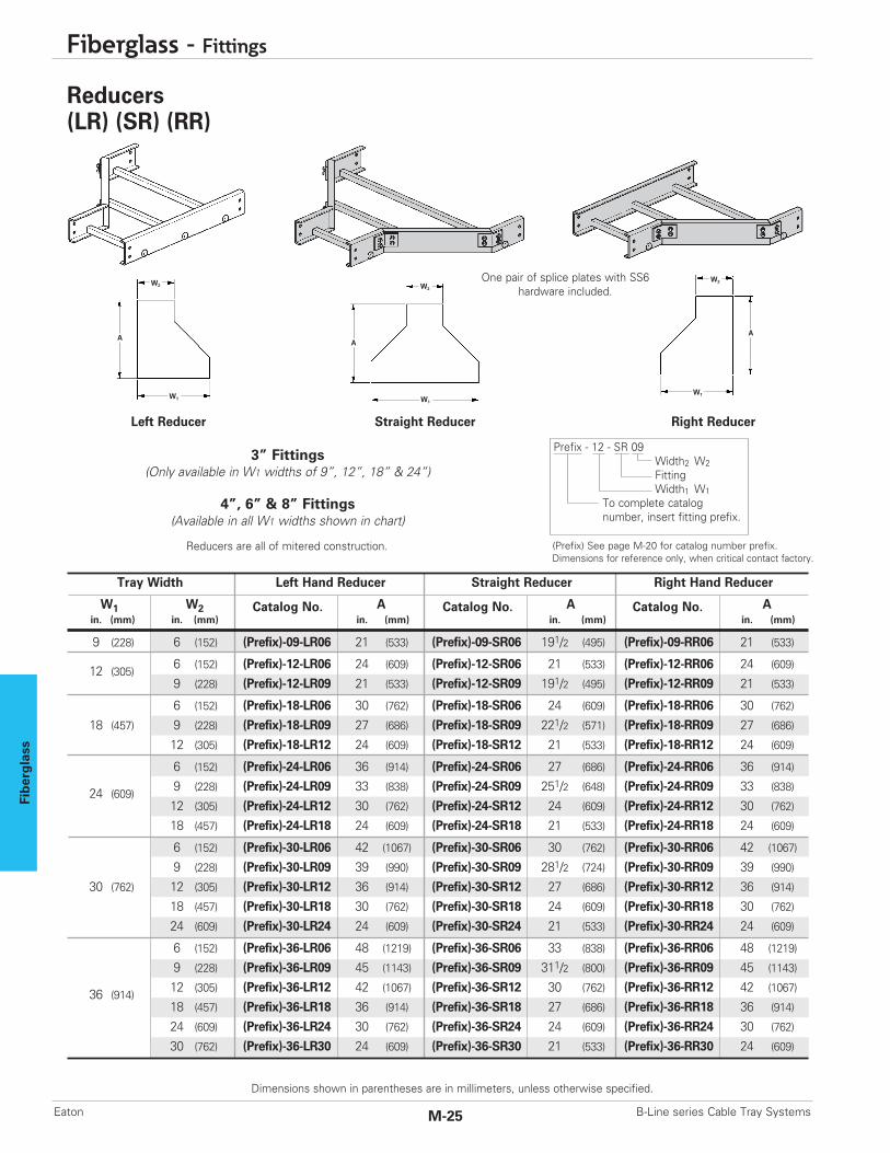
Prefix - 12 - SR 09Width2 W2FittingWidth1 W1
To complete catalog number, insert fitting prefix.
Tray Width Left Hand Reducer Straight Reducer Right Hand Reducer
W1 W2 Catalog No. A Catalog No. A Catalog No. Ain. (mm) in. (mm) in. (mm) in. (mm) in. (mm)
9 (228) 6 (152) (Prefix)-09-LR06 21 (533) (Prefix)-09-SR06 191/2 (495) (Prefix)-09-RR06 21 (533)
12 (305)6 (152) (Prefix)-12-LR06 24 (609) (Prefix)-12-SR06 21 (533) (Prefix)-12-RR06 24 (609)
9 (228) (Prefix)-12-LR09 21 (533) (Prefix)-12-SR09 191/2 (495) (Prefix)-12-RR09 21 (533)
6 (152) (Prefix)-18-LR06 30 (762) (Prefix)-18-SR06 24 (609) (Prefix)-18-RR06 30 (762)
18 (457) 9 (228) (Prefix)-18-LR09 27 (686) (Prefix)-18-SR09 221/2 (571) (Prefix)-18-RR09 27 (686)
12 (305) (Prefix)-18-LR12 24 (609) (Prefix)-18-SR12 21 (533) (Prefix)-18-RR12 24 (609)
6 (152) (Prefix)-24-LR06 36 (914) (Prefix)-24-SR06 27 (686) (Prefix)-24-RR06 36 (914)
24 (609)9 (228) (Prefix)-24-LR09 33 (838) (Prefix)-24-SR09 251/2 (648) (Prefix)-24-RR09 33 (838)
12 (305) (Prefix)-24-LR12 30 (762) (Prefix)-24-SR12 24 (609) (Prefix)-24-RR12 30 (762)
18 (457) (Prefix)-24-LR18 24 (609) (Prefix)-24-SR18 21 (533) (Prefix)-24-RR18 24 (609)
6 (152) (Prefix)-30-LR06 42 (1067) (Prefix)-30-SR06 30 (762) (Prefix)-30-RR06 42 (1067)
9 (228) (Prefix)-30-LR09 39 (990) (Prefix)-30-SR09 281/2 (724) (Prefix)-30-RR09 39 (990)
30 (762) 12 (305) (Prefix)-30-LR12 36 (914) (Prefix)-30-SR12 27 (686) (Prefix)-30-RR12 36 (914)
18 (457) (Prefix)-30-LR18 30 (762) (Prefix)-30-SR18 24 (609) (Prefix)-30-RR18 30 (762)
24 (609) (Prefix)-30-LR24 24 (609) (Prefix)-30-SR24 21 (533) (Prefix)-30-RR24 24 (609)
6 (152) (Prefix)-36-LR06 48 (1219) (Prefix)-36-SR06 33 (838) (Prefix)-36-RR06 48 (1219)
9 (228) (Prefix)-36-LR09 45 (1143) (Prefix)-36-SR09 311/2 (800) (Prefix)-36-RR09 45 (1143)
36 (914)12 (305) (Prefix)-36-LR12 42 (1067) (Prefix)-36-SR12 30 (762) (Prefix)-36-RR12 42 (1067)
18 (457) (Prefix)-36-LR18 36 (914) (Prefix)-36-SR18 27 (686) (Prefix)-36-RR18 36 (914)
24 (609) (Prefix)-36-LR24 30 (762) (Prefix)-36-SR24 24 (609) (Prefix)-36-RR24 30 (762)
30 (762) (Prefix)-36-LR30 24 (609) (Prefix)-36-SR30 21 (533) (Prefix)-36-RR30 24 (609)
W2
W1
A
W2
W1
A
W2
W1
A
Left Reducer Straight Reducer Right Reducer
Reducers are all of mitered construction.
One pair of splice plates with SS6hardware included.
Dimensions for reference only, when critical contact factory.(Prefix) See page M-20 for catalog number prefix.
Reducers(LR) (SR) (RR)
3” Fittings(Only available in W1 widths of 9”, 12”, 18” & 24”)
4”, 6” & 8” Fittings(Available in all W1 widths shown in chart)
Fiberg
lass
Dimensions shown in parentheses are in millimeters, unless otherwise specified.
Fiberglass - Fittings
M-26B-Line series Cable Tray Systems Eaton
R
W2
B
W1
A
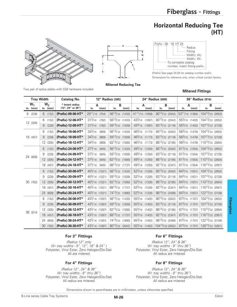
Mitered Reducing TeeTwo pair of splice plates with SS6 hardware included.
Dimensions for reference only, when critical contact factory.
(Prefix) See page M-20 for catalog number prefix.
Horizontal Reducing Tee(HT)
Prefix - 36 - 18 HT 24RadiusFittingWidth2 W2Width1 W1
To complete catalog number, insert fitting prefix.
(Radius 12” onlyW1 tray widths - 9”, 12”, 18” & 24” )
Polyester, Vinyl Ester, Zero Halogen/Dis-StatAll are mitered
For 3” Fittings
(Radius 12”, 24” & 36”W1 tray widths - 9” thru 36”)
Polyester, Vinyl Ester, Zero Halogen/Dis-StatAll radius are mitered
For 4” Fittings
(Radius 12”, 24” & 36”W1 tray widths - 9” thru 36”)
Polyester, Vinyl Ester, Zero Halogen/Dis-StatAll radius are mitered
For 6” Fittings
(Radius 12”, 24” & 36”W1 tray widths - 9” thru 36”)
Polyester, Vinyl Ester, Zero Halogen/Dis-StatAll radius are mitered
For 8” Fittings
* Insert radius(12", 24” or 36")
Tray Width Catalog No. 12" Radius (305) 24" Radius (609) 36" Radius (914)W1 W2 A B A B A B
in. (mm) in. (mm) in. (mm) in. (mm) in. (mm) in. (mm) in. (mm) in. (mm)
9 (228) 6 (152) (Prefix)-09-06-HT* 2911/16 (754) 5613/32 (1433) 4111/16 (1059) 8013/32 (2042) 5311/16 (1364) 10413/32 (2652)
12 (305)6 (152) (Prefix)-12-06-HT* 313/16 (792) 5613/32 (1433) 433/16 (1097) 8013/32 (2042) 553/16 (1402) 10413/32 (2652)
9 (228) (Prefix)-12-09-HT* 313/16 (792) 5913/32 (1509) 433/16 (1097) 8313/32 (2118) 553/16 (1402) 10713/32 (2728)
6 (152) (Prefix)-18-06-HT* 343/16 (869) 5613/32 (1433) 463/16 (1173) 8013/32 (2042) 583/16 (1478) 10413/32 (2652)
18 (457) 9 (228) (Prefix)-18-09-HT* 343/16 (869) 5913/32 (1509) 463/16 (1173) 8313/32 (2118) 583/16 (1478) 10713/32 (2728)
12 (305) (Prefix)-18-12-HT* 343/16 (869) 6213/32 (1585) 463/16 (1173) 8613/32 (2195) 583/16 (1478) 11013/32 (2804)
6 (152) (Prefix)-24-06-HT* 373/16 (945) 5613/32 (1433) 493/16 (1250) 8013/32 (2042) 613/16 (1554) 10413/32 (2652)
24 (609)9 (228) (Prefix)-24-09-HT* 373/16 (945) 5913/32 (1509) 493/16 (1250) 8313/32 (2118) 613/16 (1554) 10713/32 (2728)
12 (305) (Prefix)-24-12-HT* 373/16 (945) 6213/32 (1585) 493/16 (1250) 8613/32 (2195) 613/16 (1554) 11013/32 (2804)
18 (457) (Prefix)-24-18-HT* 373/16 (945) 6813/32 (1737) 493/16 (1250) 9213/32 (2347) 613/16 (1554) 11613/32 (2957)
6 (152) (Prefix)-30-06-HT* 403/16 (1021) 5613/32 (1433) 523/16 (1326) 8013/32 (2042) 643/16 (1631) 10413/32 (2652)
9 (228) (Prefix)-30-09-HT* 403/16 (1021) 5913/32 (1509) 523/16 (1326) 8313/32 (2118) 643/16 (1631) 10713/32 (2728)
30 (762) 12 (305) (Prefix)-30-12-HT* 403/16 (1021) 6213/32 (1585) 523/16 (1326) 8613/32 (2195) 643/16 (1631) 11013/32 (2804)
18 (457) (Prefix)-30-18-HT* 403/16 (1021) 6813/32 (1737) 523/16 (1326) 9213/32 (2347) 643/16 (1631) 11613/32 (2957)
24 (609) (Prefix)-30-24-HT* 403/16 (1021) 7413/32 (1890) 523/16 (1326) 9813/32 (2499) 643/16 (1631) 12213/32 (3109)
6 (152) (Prefix)-36-06-HT* 433/16 (1097) 5613/32 (1433) 553/16 (1402) 8013/32 (2042) 673/16 (1707) 10413/32 (2652)
9 (228) (Prefix)-36-09-HT* 433/16 (1097) 5913/32 (1509) 553/16 (1402) 8313/32 (2118) 673/16 (1707) 10713/32 (2728)
36 (914)12 (305) (Prefix)-36-12-HT* 433/16 (1097) 6213/32 (1585) 553/16 (1402) 8613/32 (2195) 673/16 (1707) 11013/32 (2804)
18 (457) (Prefix)-36-18-HT* 433/16 (1097) 6813/32 (1737) 553/16 (1402) 9213/32 (2347) 673/16 (1707) 11613/32 (2957)
24 (609) (Prefix)-36-24-HT* 433/16 (1097) 7413/32 (1890) 553/16 (1402) 9813/32 (2499) 673/16 (1707) 12213/32 (3109)
30 (762) (Prefix)-36-30-HT* 433/16 (1097) 8013/32 (2042) 553/16 (1402) 10413/32 (2652) 673/16 (1707) 12813/32 (3261)
Mitered Fittings
Fiberglass
Fiberglass - Fittings
M-27 B-Line series Cable Tray SystemsEaton
Dimensions shown in parentheses are in millimeters, unless otherwise specified.
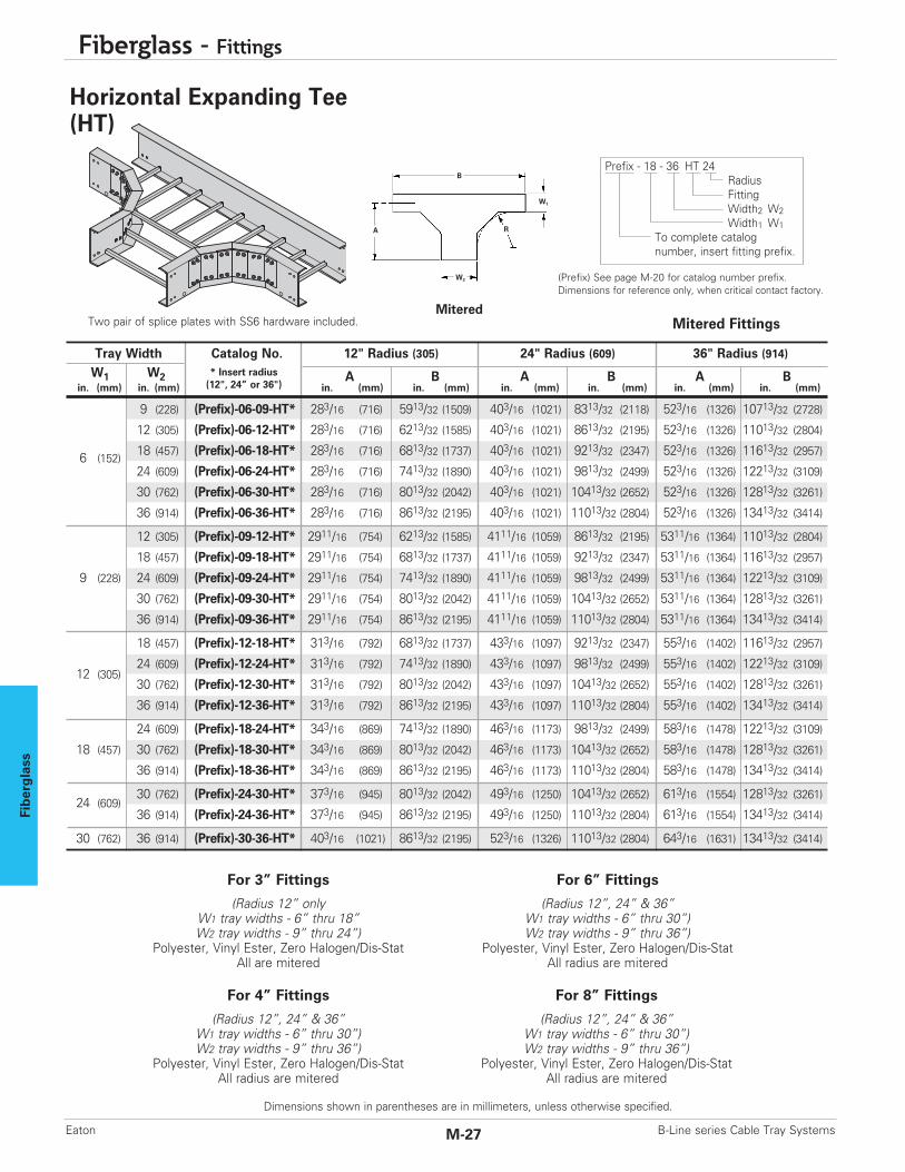
MiteredTwo pair of splice plates with SS6 hardware included.
Horizontal Expanding Tee(HT)
Prefix - 18 - 36 HT 24RadiusFittingWidth2 W2Width1 W1
To complete catalog number, insert fitting prefix.
(Radius 12” onlyW1 tray widths - 6” thru 18”W2 tray widths - 9” thru 24”)
Polyester, Vinyl Ester, Zero Halogen/Dis-StatAll are mitered
For 3” Fittings
(Radius 12”, 24” & 36”W1 tray widths - 6” thru 30”)W2 tray widths - 9” thru 36”)
Polyester, Vinyl Ester, Zero Halogen/Dis-StatAll radius are mitered
For 4” Fittings
(Radius 12”, 24” & 36”W1 tray widths - 6” thru 30”)W2 tray widths - 9” thru 36”)
Polyester, Vinyl Ester, Zero Halogen/Dis-StatAll radius are mitered
For 6” Fittings
(Radius 12”, 24” & 36”W1 tray widths - 6” thru 30”)W2 tray widths - 9” thru 36”)
Polyester, Vinyl Ester, Zero Halogen/Dis-StatAll radius are mitered
For 8” Fittings
W1
R
B
W2
A
Dimensions for reference only, when critical contact factory.(Prefix) See page M-20 for catalog number prefix.
* Insert radius(12", 24” or 36")
Tray Width Catalog No. 12" Radius (305) 24" Radius (609) 36" Radius (914)W1 W2 A B A B A B
in. (mm) in. (mm) in. (mm) in. (mm) in. (mm) in. (mm) in. (mm) in. (mm)
9 (228) (Prefix)-06-09-HT* 283/16 (716) 5913/32 (1509) 403/16 (1021) 8313/32 (2118) 523/16 (1326) 10713/32 (2728)
12 (305) (Prefix)-06-12-HT* 283/16 (716) 6213/32 (1585) 403/16 (1021) 8613/32 (2195) 523/16 (1326) 11013/32 (2804)
6 (152)18 (457) (Prefix)-06-18-HT* 283/16 (716) 6813/32 (1737) 403/16 (1021) 9213/32 (2347) 523/16 (1326) 11613/32 (2957)
24 (609) (Prefix)-06-24-HT* 283/16 (716) 7413/32 (1890) 403/16 (1021) 9813/32 (2499) 523/16 (1326) 12213/32 (3109)
30 (762) (Prefix)-06-30-HT* 283/16 (716) 8013/32 (2042) 403/16 (1021) 10413/32 (2652) 523/16 (1326) 12813/32 (3261)
36 (914) (Prefix)-06-36-HT* 283/16 (716) 8613/32 (2195) 403/16 (1021) 11013/32 (2804) 523/16 (1326) 13413/32 (3414)
12 (305) (Prefix)-09-12-HT* 2911/16 (754) 6213/32 (1585) 4111/16 (1059) 8613/32 (2195) 5311/16 (1364) 11013/32 (2804)
18 (457) (Prefix)-09-18-HT* 2911/16 (754) 6813/32 (1737) 4111/16 (1059) 9213/32 (2347) 5311/16 (1364) 11613/32 (2957)
9 (228) 24 (609) (Prefix)-09-24-HT* 2911/16 (754) 7413/32 (1890) 4111/16 (1059) 9813/32 (2499) 5311/16 (1364) 12213/32 (3109)
30 (762) (Prefix)-09-30-HT* 2911/16 (754) 8013/32 (2042) 4111/16 (1059) 10413/32 (2652) 5311/16 (1364) 12813/32 (3261)
36 (914) (Prefix)-09-36-HT* 2911/16 (754) 8613/32 (2195) 4111/16 (1059) 11013/32 (2804) 5311/16 (1364) 13413/32 (3414)
18 (457) (Prefix)-12-18-HT* 313/16 (792) 6813/32 (1737) 433/16 (1097) 9213/32 (2347) 553/16 (1402) 11613/32 (2957)
12 (305)24 (609) (Prefix)-12-24-HT* 313/16 (792) 7413/32 (1890) 433/16 (1097) 9813/32 (2499) 553/16 (1402) 12213/32 (3109)
30 (762) (Prefix)-12-30-HT* 313/16 (792) 8013/32 (2042) 433/16 (1097) 10413/32 (2652) 553/16 (1402) 12813/32 (3261)
36 (914) (Prefix)-12-36-HT* 313/16 (792) 8613/32 (2195) 433/16 (1097) 11013/32 (2804) 553/16 (1402) 13413/32 (3414)
24 (609) (Prefix)-18-24-HT* 343/16 (869) 7413/32 (1890) 463/16 (1173) 9813/32 (2499) 583/16 (1478) 12213/32 (3109)
18 (457) 30 (762) (Prefix)-18-30-HT* 343/16 (869) 8013/32 (2042) 463/16 (1173) 10413/32 (2652) 583/16 (1478) 12813/32 (3261)
36 (914) (Prefix)-18-36-HT* 343/16 (869) 8613/32 (2195) 463/16 (1173) 11013/32 (2804) 583/16 (1478) 13413/32 (3414)
24 (609)30 (762) (Prefix)-24-30-HT* 373/16 (945) 8013/32 (2042) 493/16 (1250) 10413/32 (2652) 613/16 (1554) 12813/32 (3261)
36 (914) (Prefix)-24-36-HT* 373/16 (945) 8613/32 (2195) 493/16 (1250) 11013/32 (2804) 613/16 (1554) 13413/32 (3414)
30 (762) 36 (914) (Prefix)-30-36-HT* 403/16 (1021) 8613/32 (2195) 523/16 (1326) 11013/32 (2804) 643/16 (1631) 13413/32 (3414)
Mitered Fittings

Fiberg
lass
Dimensions shown in parentheses are in millimeters, unless otherwise specified.
Fiberglass - Fittings
M-28B-Line series Cable Tray Systems Eaton
Mitered
Dimensions for reference only, when critical contact factory.(Prefix) See page M-20 for catalog number prefix.
Horizontal Expanding/Reducing Cross(HX)
(Radius 12” onlyW1 tray widths - 9” thru 24”W2 tray widths - 6” thru 18”)
Polyester, Vinyl Ester, Zero Halogen/Dis-StatAll are mitered
For 3” Fittings
(Radius 12”, 24” & 36”W1 tray widths - 9” thru 36”)W2 tray widths - 6” thru 30”)
Polyester, Vinyl Ester, Zero Halogen/Dis-StatAll radius are mitered
For 4” Fittings
(Radius 12”, 24” & 36”W1 tray widths - 9” thru 36”)W2 tray widths - 6” thru 30”)
Polyester, Vinyl Ester, Zero Halogen/Dis-StatAll radius are mitered
For 6” Fittings
(Radius 12”, 24” & 36”W1 tray widths - 9” thru 36”)W2 tray widths - 6” thru 30”)
Polyester, Vinyl Ester, Zero Halogen/Dis-StatAll radius are mitered
For 8” Fittings
B
R
W2
W1
A
Three pair of splice plates with SS6 hardware included.
Prefix - 18 - 12 HX 12RadiusFitting Width2 W2Width1 W1
To complete catalog number, insert fitting prefix.
Mitered Fittings
* Insert radius(12", 24” or 36")
Tray Width Catalog No. 12" Radius (305) 24" Radius (609) 36" Radius (914)W1 W2 A B A B A B
in. (mm) in. (mm) in. (mm) in. (mm) in. (mm) in. (mm) in. (mm) in. (mm)
9 (228) 6 (152) (Prefix)-09-06-HX* 283/16 (716) 5913/32 (1509) 403/16 (1021) 8313/32 (2118) 523/16 (1326) 10713/32 (2728)
12 (305)6 (152) (Prefix)-12-06-HX* 283/16 (716) 6213/32 (1585) 403/16 (1021) 8613/32 (2195) 523/16 (1326) 11013/32 (2804)
9 (228) (Prefix)-12-09-HX* 2911/16 (754) 6213/32 (1585) 4111/16 (1059) 8613/32 (2195) 5311/16 (1364) 11013/32 (2804)
6 (152) (Prefix)-18-06-HX* 283/16 (716) 6813/32 (1737) 403/16 (1021) 9213/32 (2347) 523/16 (1326) 11613/32 (2957)
18 (457) 9 (228) (Prefix)-18-09-HX* 2911/16 (754) 6813/32 (1737) 4111/16 (1059) 9213/32 (2347) 5311/16 (1364) 11613/32 (2957)
12 (305) (Prefix)-18-12-HX* 313/16 (792) 6813/32 (1737) 433/16 (1097) 9213/32 (2347) 553/16 (1402) 11613/32 (2957)
6 (152) (Prefix)-24-06-HX* 283/16 (716) 7413/32 (1890) 403/16 (1021) 9813/32 (2499) 523/16 (1326) 12213/32 (3109)
24 (609)9 (228) (Prefix)-24-09-HX* 2911/16 (754) 7413/32 (1890) 4111/16 (1059) 9813/32 (2499) 5311/16 (1364) 12213/32 (3109)
12 (305) (Prefix)-24-12-HX* 313/16 (792) 7413/32 (1890) 433/16 (1097) 9813/32 (2499) 553/16 (1402) 12213/32 (3109)
18 (457) (Prefix)-24-18-HX* 343/16 (869) 7413/32 (1890) 463/16 (1173) 9813/32 (2499) 583/16 (1478) 12213/32 (3109)
6 (152) (Prefix)-30-06-HX* 283/16 (716) 8013/32 (2042) 403/16 (1021) 10413/32 (2652) 523/16 (1326) 12813/32 (3261)
9 (228) (Prefix)-30-09-HX* 2911/16 (754) 8013/32 (2042) 4111/16 (1059) 10413/32 (2652) 5311/16 (1364) 12813/32 (3261)
30 (762) 12 (305) (Prefix)-30-12-HX* 313/16 (792) 8013/32 (2042) 433/16 (1097) 10413/32 (2652) 553/16 (1402) 12813/32 (3261)
18 (457) (Prefix)-30-18-HX* 343/16 (869) 8013/32 (2042) 463/16 (1173) 10413/32 (2652) 583/16 (1478) 12813/32 (3261)
24 (609) (Prefix)-30-24-HX* 373/16 (945) 8013/32 (2042) 493/16 (1250) 10413/32 (2652) 613/16 (1554) 12813/32 (3261)
6 (152) (Prefix)-36-06-HX* 283/16 (716) 8613/32 (2195) 403/16 (1021) 11013/32 (2804) 523/16 (1326) 13413/32 (3414)
9 (228) (Prefix)-36-09-HX* 2911/16 (754) 8613/32 (2195) 4111/16 (1059) 11013/32 (2804) 5311/16 (1364) 13413/32 (3414)
36 (914)12 (305) (Prefix)-36-12-HX* 313/16 (792) 8613/32 (2195) 433/16 (1097) 11013/32 (2804) 553/16 (1402) 13413/32 (3414)
18 (457) (Prefix)-36-18-HX* 343/16 (869) 8613/32 (2195) 463/16 (1173) 11013/32 (2804) 583/16 (1478) 13413/32 (3414)
24 (609) (Prefix)-36-24-HX* 373/16 (945) 8613/32 (2195) 493/16 (1250) 11013/32 (2804) 613/16 (1554) 13413/32 (3414)
30 (762) (Prefix)-36-30-HX* 403/16 (1021) 8613/32 (2195) 523/16 (1326) 11013/32 (2804) 643/16 (1631) 13413/32 (3414)

Fiberglass
Fiberglass - Fittings
M-29 B-Line series Cable Tray SystemsEaton
Dimensions shown in parentheses are in millimeters, unless otherwise specified.
Vertical Bends 90°(VO) (VI)
(Radius 12” only • Tray widths - 6” thru 24”)Polyester, Vinyl Ester, Zero Halogen/Dis-Stat
All are mitered
For 3” Fittings
(Radius 12”, 24” & 36”Tray widths - 6” thru 36”)
Polyester, Vinyl Ester, Zero Halogen/Dis-StatAll radius are mitered
For 4” Fittings
(Radius 12”, 24” & 36”Tray widths - 6” thru 36”)
Polyester, Vinyl Ester, Zero Halogen/Dis-StatAll radius are mitered
For 6” Fittings
(Radius 12”, 24” & 36”Tray widths - 6” thru 36”)
Polyester, Vinyl Ester, Zero Halogen/Dis-StatAll radius are mitered
For 8” Fittings
Vertical Inside Bend
A
B
R
90˚ (VI) Mitered90˚ (VO) Mitered
VerticalOutside Bend
VO VI
Prefix - 06 - 90 VI 24RadiusFittingAngleWidth
To complete catalog number, insert fitting prefix.
Prefix - 06 - 90 VO 24RadiusFittingAngleWidth
To complete catalog number, insert fitting prefix.
One pair of splice plates withSS6 hardware included.
(Prefix) See page M-20 for catalog number prefix. Dimensions for reference only, when critical contact factory.
- R - 90˚ MiteredBend Tray VO & VI BendRadius Width Catalog No. A Bin. (mm) in. (mm) in. / (mm) in. / (mm)
6 (152) (Prefix)-06-90(*)12
9 (228) (Prefix)-09-90(*)12
12 (305) (Prefix)-12-90(*)12
12 (305) 18 (457) (Prefix)-18-90(*)12275⁄32 275⁄32
24 (609) (Prefix)-24-90(*)12(690) (690)
30 (762) (Prefix)-30-90(*)12
36 (914) (Prefix)-36-90(*)12
6 (152) (Prefix)-06-90(*)24
9 (228) (Prefix)-09-90(*)24
12 (305) (Prefix)-12-90(*)24
24 (609) 18 (457) (Prefix)-18-90(*)243623⁄32 3623⁄32
24 (609) (Prefix)-24-90(*)24(933) (933)
30 (762) (Prefix)-30-90(*)24
36 (914) (Prefix)-36-90(*)24
6 (152) (Prefix)-06-90(*)36
9 (228) (Prefix)-09-90(*)36
12 (305) (Prefix)-12-90(*)36
36 (914) 18 (457) (Prefix)-18-90(*)364429⁄32 4429⁄32
24 (609) (Prefix)-24-90(*)36(1141) (1141)
30 (762) (Prefix)-30-90(*)36
36 (914) (Prefix)-36-90(*)36
(*) Insert ‘VO’ for Vertical Outside Bend or ‘VI’ for Vertical Inside Bend.
B
AR

Fiberg
lass
Dimensions shown in parentheses are in millimeters, unless otherwise specified.
Fiberglass - Fittings
M-30B-Line series Cable Tray Systems Eaton
Vertical Bends 45°(VO) (VI)
(Radius 12” only • Tray widths - 6” thru 24”)Polyester, Vinyl Ester, Zero Halogen/Dis-Stat
All are mitered
For 3” Fittings
(Radius 12”, 24” & 36”Tray widths - 6” thru 36”)
Polyester, Vinyl Ester, Zero Halogen/Dis-StatAll radius are mitered
For 4” Fittings
(Radius 12”, 24” & 36”Tray widths - 6” thru 36”)
Polyester, Vinyl Ester, Zero Halogen/Dis-StatAll radius are mitered
For 6” Fittings
(Radius 12”, 24” & 36”Tray widths - 6” thru 36”)
Polyester, Vinyl Ester, Zero Halogen/Dis-StatAll radius are mitered
For 8” Fittings
Vertical Inside Bend
VerticalOutside Bend
VO VI
Prefix - 06 - 45 VI 24RadiusFittingAngleWidth
To complete catalog number, insert fitting prefix.
Prefix - 06 - 45 VO 24RadiusFittingAngleWidth
To complete catalog number, insert fitting prefix.
One pair of splice plates withSS6 hardware included.
45˚ (VI) Mitered45˚ (VO) Mitered
(Prefix) See page M-20 for catalog number prefix. Dimensions for reference only, when critical contact factory.
45˚ Mitered- R -Bend Tray VO & VI Bend
Radius Width Catalog No. A B Cin. mm in. mm in. / (mm) in. / (mm) in. / (mm)
6 (152) (Prefix)-06-45(*)12
9 (228) (Prefix)-09-45(*)12
12 (305) (Prefix)-12-45(*)12
12 (305) 18 (457) (Prefix)-18-45(*)12231⁄16 99⁄16 131⁄2
24 (609) (Prefix)-24-45(*)12(585) (242) (343)
30 (762) (Prefix)-30-45(*)12
36 (914) (Prefix)-36-45(*)12
6 (152) (Prefix)-06-45(*)24
9 (228) (Prefix)-09-45(*)24
12 (305) (Prefix)-12-45(*)24
24 (609) 18 (457) (Prefix)-18-45(*)24231⁄16 99⁄16 131⁄2
24 (609) (Prefix)-24-45(*)24(585) (242) (343)
30 (762) (Prefix)-30-45(*)24
36 (914) (Prefix)-36-45(*)24
6 (152) (Prefix)-06-45(*)36
9 (228) (Prefix)-09-45(*)36
12 (305) (Prefix)-12-45(*)36
36 (914) 18 (457) (Prefix)-18-45(*)36231⁄16 99⁄16 131⁄2
24 (609) (Prefix)-24-45(*)36(585) (242) (343)
30 (762) (Prefix)-30-45(*)36
36 (914) (Prefix)-36-45(*)36
(*) Insert ‘VO’ for Vertical Outside Bend or ‘VI’ for Vertical Inside Bend.60˚ and 30˚ vertical bends available in mitered construction.
R
B
A
C
C RA
B
C
C

Fiberglass
Fiberglass - Covers & Cover Accessories
M-31 B-Line series Cable Tray SystemsEaton
Dimensions shown in parentheses are in millimeters, unless otherwise specified.
Covers
Material Thickness: .090" (2.3)Cover Length: 10' (3m)Standard Mounting Hardware: (10 each) #10 x 3⁄4"stainless, self drilling screws provided with each section
Covers F C - 24 - 120Length or fitting descriptionWidthRail designMaterial
F C - 24 - 120 = Flat polyesterFV C - 24 - 120 = Flat vinyl esterFA C - 24 - 120 = Flat zero halogen/Dis-StatFP C - 24 - 120 = Peaked polyester
FVP C - 24 - 120 = Peaked vinyl esterFAP C - 24 - 120 = Peaked zero halogen/Dis-Stat
Peaked Cover provides 1 to 3.7 pitchPeaked covers available for straight sections only.
No Hardware provided.
Quantity of StandardCover Clamps Required
Straight Section 60" or 72" ............................................ 4 pcs.Straight Section 120" or 144" ...................................... 6 pcs.Horizontal/Vertical Bends .............................................. 4 pcs.Tees .......................................................................................... 6 pcs.Crosses .................................................................................. 8 pcs.
Note: When using the Heavy Duty Cover Clamp, onlyone-half the number of clamps stated above is required.
Catalog No. Side Rail Heightin. (mm)
9(Δ)-9013 3 (76)
9(Δ)-9014 4 (101)
9(Δ)-9016 6 (152)
Standard Cover Clamp• Furnished in pairs with hardware.
Green = Fastest shipped items Black = Normal lead-time items Red = Normally long lead-time items
Catalog No. Side Rail Heightin. (mm)
9F-W-9034 3 (76)
9F-W-9044 4 (101)
9F-W-9064 6 (152)
9F-W-9084 8 (203)
Heavy Duty Cover ClampRecommended for outdoor service.• W = tray width• Heavy duty cover clamp availablefor flat covers only
Catalog No. Side Rail Heightin. (mm)
9F-W-9034P 3 (76)
9F-W-9044P 4 (101)
9F-W-9064P 6 (152)
9F-W-9084P 8 (203)
Peaked Cover Clamp• W = tray width
Catalog No.
TPDR
Thermo Plastic Drive Rivet• Sold individually.• Shipped in packages of 25 pcs.
Material Designations(Δ) Insert one of the following material designations when required.
F = Polyester Resin (Example: 9F-9013)FV = Vinyl Ester Resin (Example: 9FV-9013)FA = Zero Halogen/Dis-Stat Resin (Example: 9FA-9013)

Fiberg
lass
Fiberglass - Accessories
M-32B-Line series Cable Tray Systems Eaton
Material Height Catalog No.in. (mm)
3" (76) 9(Δ)-4003SS6
Fiberglass4" (101) 9(Δ)-4004SS66" (152) 9(Δ)-8006SS68" (203) 9(Δ)-8008SS6
Material Height Catalog No.in. (mm)
3" (76) 9(Δ)-4013SS6
Fiberglass4" (101) 9(Δ)-4014SS66" (152) 9(Δ)-8016SS68" (203) 9(Δ)-8018SS6
Material Height Catalog No.in. (mm)
3" (76) 9(Δ)-4053SS6
Fiberglass4" (101) 9(Δ)-4054SS66" (152) 9(Δ)-8056SS68" (203) 9(Δ)-8058SS6
(Δ) See page M-31 for material selection Dimensions shown in parentheses are in millimeters, unless otherwise specified.
Standard Lay-In Splice Plates• Furnished in pairs with 316 stainless steel hardware• One pair including hardware provided with straight section.(Expansion splice quantity subtracted)
Expansion Lay-In Splice Plates
• Furnished in pairs with 316 stainless steel hardware
Tray to Box Splice PlatesThese plates are used to attach the end of a tray run to a distribution box or control center. • Furnished in pairs with316 stainless steel hardware
Material Height Catalog No.in. (mm)
8” to 6” (203 to 152) 9(Δ)-8086SS6
Fiberglass8” to 4” (203 to 101) 9(Δ)-8084SS66” to 3” (152 to 76) 9(Δ)-8063SS66” to 4” (152 to 101) 9(Δ)-8064SS64” to 3” (101 to 76) 9(Δ)-4043SS6
Step Down Splice PlatesThese plates are offered for connecting cable traysections having side rails of different heights. • Furnished in pairs with 316 stainless steel hardware
Material Height Catalog No.in. (mm)
3" (76) 9(Δ)-1083-WSS6
Fiberglass4" (101) 9(Δ)-1084-WSS66" (152) 9(Δ)-1086-WSS68" (203) 9(Δ)-1088-WSS6
Blind End PlateThis plate forms a closure for any tray that dead ends.• Furnished as one plate• W = tray width
Resin Seal KitTo reseal fiberglass after field modifications.• 1 pint (473ml)Contents: Sealant and Applicator.
Part Number with Hardware Explanation Note: All hardware is 3/8”
Example: 9F-4004 SS6: pair of 4-hole splice plates for 4" (101) system with stainless steel hardware9FV-8006 SS6: pair of 8-hole vinyl ester splice plates for 6" (152) system with stainless steel hardware
Hardware 316 Stainless SteelOption SS6
Resin Seal Kit
Catalog No.
RSK-010

Fiberglass
Fiberglass - Accessories
M-33 B-Line series Cable Tray SystemsEaton
Material Height Catalog No.in. (mm)
3" (76) 9F-4033SS6
Fiberglass4" (101) 9F-4034SS66" (152) 9F-8036SS68" (203) 9F-8038SS6
Material Height Catalog No.in. (mm) 90° 45° 30°
3" (76) 9(Δ)-4903HSS6 9(Δ)-4453HSS6 9(Δ)-4303HSS6
Fiberglass4" (101) 9(Δ)-4904HSS6 9(Δ)-4454HSS6 9(Δ)-4304HSS66" (152) 9(Δ)-8906HSS6 9(Δ)-8456HSS6 9(Δ)-8306HSS68" (203) 9(Δ)-8908HSS6 9(Δ)-8458HSS6 9(Δ)-8308HSS6
Material Height Catalog No.in. (mm) 90° 45° 30°
3" (76) 9(Δ)-4903VSS6 9(Δ)-4453VSS6 9(Δ)-4303VSS6
Fiberglass4" (101) 9(Δ)-4904VSS6 9(Δ)-4454VSS6 9(Δ)-4304VSS66" (152) 9(Δ)-8906VSS6 9(Δ)-8456VSS6 9(Δ)-8306VSS68" (203) 9(Δ)-8908VSS6 9(Δ)-8458VSS6 9(Δ)-8308VSS6
Horizontal Adjustable Splice PlatesThese plates provide for changes in the horizontal direction that do not conform to standard fittings. • Furnished in pairs with 316 stainless steel hardware• Body made from 316 stainless steel • Used for all material finishes
Horizontal Splice Plates• Furnished in pairs with 316 stainless steel hardware
Vertical Splice Plates• Furnished in pairs with316 stainless steel hardware
Material Height Catalog No.in. (mm)
3" (76) 9(Δ)-4023SS6
Fiberglass4" (101) 9(Δ)-4024SS66" (152) 9(Δ)-8026SS68" (203) 9(Δ)-8028SS6
Vertical Adjustable Splice PlatesThese plates provide for changes in elevation thatdo not conform to standard vertical fittings. • Furnished in pairs with316 stainless steel hardware
(Δ) See page M-31 for material selection Dimensions shown in parentheses are in millimeters, unless otherwise specified.

Fiberg
lass
Fiberglass - Accessories
M-34B-Line series Cable Tray Systems Eaton
VO
VI
7* (Δ) - 90 VO 24RadiusVI or VOAngleMaterialBarrier Size
Catalog Conduit SizeNo. in. (mm)
9FV-2008 0.50 (15)9FV-2009 0.75 (20)9FV-2010 1.00 (25)9FV-2011 1.25 (32)9FV-2012 1.50 (40)9FV-2013 2.00 (50)9FV-2014 2.50 (65)9FV-2015 3.00 (80)9FV-2016 3.50 (90)9FV-2017 4.00 (100)
Kit Contents:1 pc — 72" (1829) Straight Barrier 4 pc — 9F-9002 Barrier Strip Clip8 pc — Thermo Plastic Drive Rivet4 pc — #10 x 3⁄4" Stainless Steel Self-Drilling ScrewAssembly required — directions included.
Catalog Side Rail HeightNo. in. (mm)
72(Δ)-120 3" (76)73(Δ)-120 4" (101)75(Δ)-120 6" (152)77(Δ)-120 8" (203)
Catalog No.
9(Δ)-1104-W
Catalog No.
9F-1208
Catalog Side Rail HeightNo. in. (mm)
72(Δ)-90HBFL 3" (76)73(Δ)-90HBFL 4" (101)75(Δ)-90HBFL 6" (152)77(Δ)-90HBFL 8" (203)
(Δ) See page M-31 for material selection Dimensions shown in parentheses are in millimeters, unless otherwise specified.
Ladder Drop-OutSpecially-designed Ladder Drop-Outs provide a rounded surface with adequate radius to protect cable as it exits from the tray, preventing damage to insulation. • 4" (101) radius• W = tray width• Furnished with #10 x 3⁄4" self-drilling stainless steel screws
Barriers• Furnished with #10 x 3⁄4" self-drilling stainless steel screws
Flexible Horizontal Barrier KitOne kit allows up to a 36" (914) radius position of the barrier.
Vertical Bend Barriers• Furnished with #10 x 3⁄4" self-drilling stainless steel screws* Insert 2 for 3" (76) siderail height
3 for 4" (101) siderail height5 for 6" (152) siderail height
Clamp/Guide - Fiberglass• Nonmetallic• Designed for 3⁄8" hardware - not included• Combination hold down clamp and guide• Material: Glass reinforced polyurethane• Sold in pairs
Fiberglass Conduit to Cable Tray Adapter• For rigid or PVC conduit• Furnished in pairs with 316 stainless steel hardware

Fiberglass
Fiberglass - Cable Channel & Fittings
M-35 B-Line series Cable Tray SystemsEaton
Catalog No. Width Length Height Load
Ventilated Non-Ventilated in. (mm) ft. (m) in. (mm) Lbs/Ft (kg/m)
(*)-03-120 (*)N-03-120 3 (76) 10 (3) 1 (25) 8 (12)(*)-03-240 (*)N-03-240 3 (76) 20 (6) 1 (25) 8 (12)
(*)-04-120 (*)N-04-120 4 (101) 10 (3) 11⁄8 (28) 12 (18)(*)-04-240 (*)N-04-240 4 (101) 20 (6) 11⁄8 (28) 12 (18)
(*)-06-120 (*)N-06-120 6 (152) 10 (3) 15⁄8 (35) 58 (86)(*)-06-240 (*)N-06-240 6 (152) 20 (6) 15⁄8 (35) 58 (86)
(*)-08-120 (*)N-08-120 8 (203) 10 (3) 23⁄16 (55) 87 (129)(*)-08-240 (*)N-08-240 8 (203) 20 (6) 23⁄16 (55) 87 (129)
Cable Channel Fittings
FCC Fiberglass Cable Channel Ventilated
FCCN Fiberglass Cable Channel Non-Ventilated
Horizontal 3" series 4" series 6" series 8" series
90˚ (*)N-03-90HB12 (*)N-04-90HB12 (*)N-06-90HB12 (*)N-08-90HB1245˚ (*)N-03-45HB12 (*)N-04-45HB12 (*)N-06-45HB12 (*)N-08-45HB12
All fittings are of mitered construction with 12" (305) radius.
Straight Section
VO
VI
Vertical 3" series 4" series 6" series 8" series
90˚ (*)N-03-90V*12 (*)N-04-90V*12 (*)N-06-90V*12 (*)N-08-90V*1245˚ (*)N-03-45V*12 (*)N-04-45V*12 (*)N-06-45V*12 (*)N-08-45V*12
One pair of splice plates included.
One pair of splice plates included.
• Load data was interpolated from CSA testing.• Loads shown are for FCCN series.• Loads shown are for 6 ft. (1.83m) span with deflection of .7 (18.26) inches.
• One pair of splice plates included with each straight section.
Green = Fastest shipped items Black = Normal lead-time items Red = Normally long lead-time items
Dimensions shown in parentheses are in millimeters, unless otherwise specified.
(*) Insert material typeFCC for Polyester ResinFCCV for Vinyl Ester ResinFCCA for Zero Halogen/Dis-Stat Resin
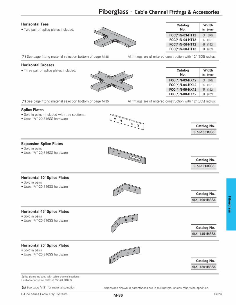
Fiberg
lass
Fiberglass - Cable Channel Fittings & Accessories
M-36B-Line series Cable Tray Systems Eaton
Splice plates included with cable channel sections.Hardware for splice plates is 1/4”-20 (316SS).
Catalog WidthNo. in. (mm)
FCC(*)N-03-HT12 3 (76)FCC(*)N-04-HT12 4 (101)FCC(*)N-06-HT12 6 (152)FCC(*)N-08-HT12 8 (203)
All fittings are of mitered construction with 12" (305) radius.
(Δ) See page M-31 for material selection
(*) See page fitting material selection bottom of page M-35
Dimensions shown in parentheses are in millimeters, unless otherwise specified.
Catalog No.
9(Δ)-1013SS6
Horizontal Tees• Two pair of splice plates included.
Catalog WidthNo. in. (mm)
FCC(*)N-03-HX12 3 (76)FCC(*)N-04-HX12 4 (101)FCC(*)N-06-HX12 6 (152)FCC(*)N-08-HX12 8 (203)
All fittings are of mitered construction with 12" (305) radius.(*) See page fitting material selection bottom of page M-35
Horizontal Crosses• Three pair of splice plates included.
Expansion Splice Plates • Sold in pairs• Uses 1/4”-20 316SS hardware
Catalog No.
9(Δ)-1001SS6
Splice Plates • Sold in pairs - included with tray sections.• Uses 1/4”-20 316SS hardware
Catalog No.
9(Δ)-1901HSS6
Horizontal 90˚ Splice Plates • Sold in pairs• Uses 1/4”-20 316SS hardware
Catalog No.
9(Δ)-1451HSS6
Horizontal 45˚ Splice Plates • Sold in pairs• Uses 1/4”-20 316SS hardware
Catalog No.
9(Δ)-1301HSS6
Horizontal 30˚ Splice Plates • Sold in pairs• Uses 1/4”-20 316SS hardware

Fiberglass
Fiberglass - Cable Channel Accessories
M-37 B-Line series Cable Tray SystemsEaton
Green = Fastest shipped items Black = Normal lead-time items Red = Normally long lead-time items
Dimensions shown in parentheses are in millimeters, unless otherwise specified.
Catalog No.
9(Δ)-1451VSS6
Horizontal 45˚ Splice Plates • Sold in pairs• Uses 1/4”-20 316SS hardware
Catalog No.
9(Δ)-1901VSS6
Horizontal 90˚ Splice Plates • Sold in pairs• Uses 1/4”-20 316SS hardware
Catalog No.
9(Δ)-1301VSS6
Horizontal 30˚ Splice Plates • Sold in pairs• Uses 1/4”-20 316SS hardware
Catalog No.
9(Δ)-1023SS6
Horizontal Adjustable Splice Plates • Sold per piece• Uses 3/8”-16 316SS hardware
Catalog No.
9F-1033SS6
Vertical Adjustable Splice Plates • Sold per piece• Uses 3/8”-16 316SS hardware• Boby made from 316 stainless steel• Used for all material finishes
Expansion Guide Clamp• Sold per clamp• Order 1/2" hardware separately
Hold-Down Clamp• Sold per clamp• Order 1/2" hardware separately
Catalog WidthNo. in. (mm)
9SS6-1248-3 3 (76)9SS6-1248-4 4 (101)9SS6-1248-6 6 (152)9SS6-1248-8 8 (203)
Catalog WidthNo. in. (mm)
9SS6-1247-3 3 (76)9SS6-1247-4 4 (101)9SS6-1247-6 6 (152)9SS6-1247-8 8 (203)
(Δ) See page M-31 for material selection

Fiberg
lass
Fiberglass - Appendix
M-38B-Line series Cable Tray Systems Eaton
Rung design provides:- 2" (50.8) cable support surface- Both mechanical and adhesive rungto side rail connection
Marine Rung Cable Tray/Fiberglass
Features:• For Coast Guard Requirements- Allows stainless steel banding of cables- 5/32" (15.9) slots 1” (25.4) on centers- Accommodates up to 5/8" (15.9) banding
• Has applications on land- Vertical installation- Any location where extra cable positioning is required
• Designed for Earton’s B-Line series Fiberglass Cable Trays
• Part Number Indication- Add MR after rung spacing- Example: 46F09MR-36-240
1"(25.4)
1"(25.4)
2"(50.8)
1/4"(6.3)
1"(25.4)
Dimensions shown in parentheses are in millimeters, unless otherwise specified.