Fiberglass - Cooper Industries Fiberglass Strut systems are manufactured from glass fiber-reinforced...
18
We offer two fire retardant (FR) resins for strut systems, polyester and vinyl ester. Both resins are ideal for corrosive environments. While polyester is sufficient for most uses, vinyl ester is suitable for a broader range of environments. Please refer to the "Corrosion Resistance Guide" for specific applications, page 184. Materials & Finishes Our Fiberglass Strut systems are manufactured from glass fiber-reinforced plastic shapes that meet ASTM E-84, Class 1 Flame Rating and self-extinguishing requirements of ASTM D-635. A surface veil is applied during pultrusion to insure a resin-rich surface and ultraviolet resistance. Fittings The following dimensions apply to all fittings except as noted on the drawings: Hole Size – 13 /32” (10.3 mm) Dia. Hole Spacing – 13 /16” (20.6 mm) from end and 1 7 /8” (47.6 mm) on center. Width – 1 5 /8” (41.3 mm) Thickness – 1 /4” (6.3 mm) Metric Metric dimensions are shown in parentheses. Unless noted, all metric dimensions are in millimeters. Fiberglass Materials Fiberglass Strut Systems 183
-
Upload
vuongnguyet -
Category
Documents
-
view
222 -
download
2
Transcript of Fiberglass - Cooper Industries Fiberglass Strut systems are manufactured from glass fiber-reinforced...

We offer two fire retardant (FR) resins for strut systems, polyester and vinyl ester. Both resins are ideal for corrosiveenvironments.
While polyester is sufficient for most uses, vinyl ester is suitable for a broader range of environments.
Please refer to the "Corrosion Resistance Guide" for specific applications, page 184.
Materials & Finishes
Our Fiberglass Strut systems are manufactured from glass fiber-reinforced plastic shapes that meet ASTM E-84, Class1 Flame Rating and self-extinguishing requirements of ASTM D-635. A surface veil is applied during pultrusion to insurea resin-rich surface and ultraviolet resistance.
Fittings
The following dimensions apply to all fittings except as noted on the drawings:
Hole Size – 13/32” (10.3 mm) Dia.Hole Spacing – 13/16” (20.6 mm) from end and 17/8” (47.6 mm) on center.Width – 15/8” (41.3 mm)
Thickness – 1/4” (6.3 mm)
MetricMetric dimensions are shown in parentheses. Unless noted, all metric dimensions are in millimeters.
Fiberglass Materials
Fiberglass
Strut Systems183
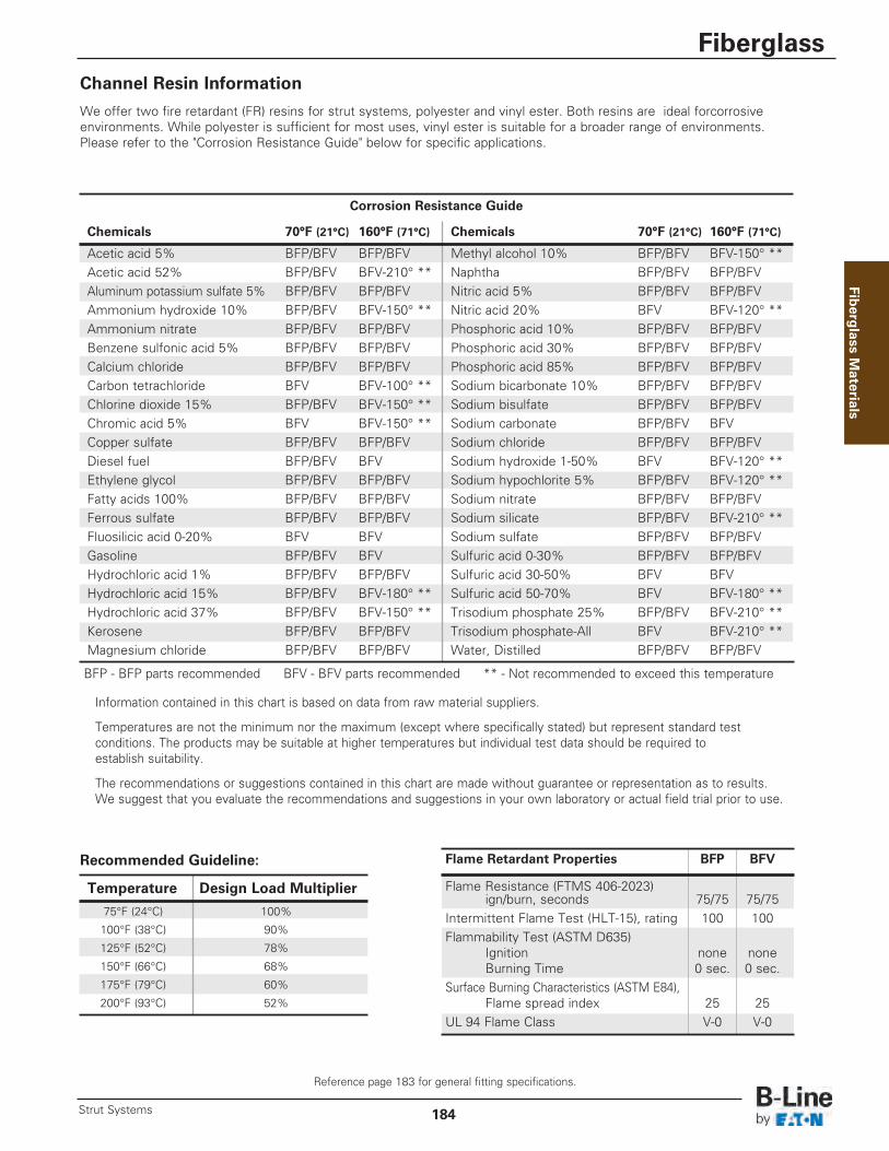
Channel Resin Information
We offer two fire retardant (FR) resins for strut systems, polyester and vinyl ester. Both resins are ideal forcorrosive environments. While polyester is sufficient for most uses, vinyl ester is suitable for a broader range of environments. Please refer to the "Corrosion Resistance Guide" below for specific applications.
Corrosion Resistance Guide
Chemicals 70°F (21°C) 160°F (71°C) Chemicals 70°F (21°C) 160°F (71°C)
Acetic acid 5% BFP/BFV BFP/BFV Methyl alcohol 10% BFP/BFV BFV-150° **Acetic acid 52% BFP/BFV BFV-210° ** Naphtha BFP/BFV BFP/BFVAluminum potassium sulfate 5% BFP/BFV BFP/BFV Nitric acid 5% BFP/BFV BFP/BFVAmmonium hydroxide 10% BFP/BFV BFV-150° ** Nitric acid 20% BFV BFV-120° **Ammonium nitrate BFP/BFV BFP/BFV Phosphoric acid 10% BFP/BFV BFP/BFVBenzene sulfonic acid 5% BFP/BFV BFP/BFV Phosphoric acid 30% BFP/BFV BFP/BFVCalcium chloride BFP/BFV BFP/BFV Phosphoric acid 85% BFP/BFV BFP/BFVCarbon tetrachloride BFV BFV-100° ** Sodium bicarbonate 10% BFP/BFV BFP/BFVChlorine dioxide 15% BFP/BFV BFV-150° ** Sodium bisulfate BFP/BFV BFP/BFVChromic acid 5% BFV BFV-150° ** Sodium carbonate BFP/BFV BFVCopper sulfate BFP/BFV BFP/BFV Sodium chloride BFP/BFV BFP/BFVDiesel fuel BFP/BFV BFV Sodium hydroxide 1-50% BFV BFV-120° **Ethylene glycol BFP/BFV BFP/BFV Sodium hypochlorite 5% BFP/BFV BFV-120° **Fatty acids 100% BFP/BFV BFP/BFV Sodium nitrate BFP/BFV BFP/BFVFerrous sulfate BFP/BFV BFP/BFV Sodium silicate BFP/BFV BFV-210° **Fluosilicic acid 0-20% BFV BFV Sodium sulfate BFP/BFV BFP/BFVGasoline BFP/BFV BFV Sulfuric acid 0-30% BFP/BFV BFP/BFVHydrochloric acid 1% BFP/BFV BFP/BFV Sulfuric acid 30-50% BFV BFVHydrochloric acid 15% BFP/BFV BFV-180° ** Sulfuric acid 50-70% BFV BFV-180° **Hydrochloric acid 37% BFP/BFV BFV-150° ** Trisodium phosphate 25% BFP/BFV BFV-210° **Kerosene BFP/BFV BFP/BFV Trisodium phosphate-All BFV BFV-210° **Magnesium chloride BFP/BFV BFP/BFV Water, Distilled BFP/BFV BFP/BFV
BFP - BFP parts recommended BFV - BFV parts recommended ** - Not recommended to exceed this temperature
Information contained in this chart is based on data from raw material suppliers.
Temperatures are not the minimum nor the maximum (except where specifically stated) but represent standard test conditions. The products may be suitable at higher temperatures but individual test data should be required toestablish suitability.
The recommendations or suggestions contained in this chart are made without guarantee or representation as to results. We suggest that you evaluate the recommendations and suggestions in your own laboratory or actual field trial prior to use.
Flame Retardant Properties BFP BFV
Flame Resistance (FTMS 406-2023) ign/burn, seconds 75/75 75/75
Intermittent Flame Test (HLT-15), rating 100 100Flammability Test (ASTM D635)
Ignition none noneBurning Time 0 sec. 0 sec.
Surface Burning Characteristics (ASTM E84),Flame spread index 25 25
UL 94 Flame Class V-0 V-0
Recommended Guideline:
Temperature Design Load Multiplier
75°F (24°C) 100%
100°F (38°C) 90%
125°F (52°C) 78%
150°F (66°C) 68%
175°F (79°C) 60%
200°F (93°C) 52%
Fiberg
lass Materials
Reference page 183 for general fitting specifications.
Fiberglass
184Strut Systems
15/8” (41.3)
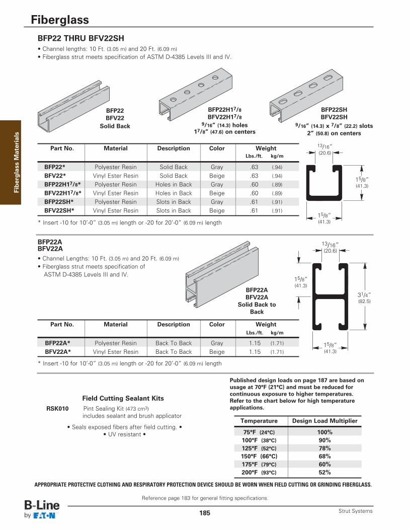
Part No. Material Description Color WeightLbs./ft. kg/m
BFP22* Polyester Resin Solid Back Gray .63 (.94)
BFV22* Vinyl Ester Resin Solid Back Beige .63 (.94)
BFP22H17/8* Polyester Resin Holes in Back Gray .60 (.89)
BFV22H17/8* Vinyl Ester Resin Holes in Back Beige .60 (.89)
BFP22SH* Polyester Resin Slots in Back Gray .61 (.91)
BFV22SH* Vinyl Ester Resin Slots in Back Beige .61 (.91)
BFP22H17/8BFV22H17/8
9/16” (14.3) holes17/8” (47.6) on centers
BFP22BFV22
Solid Back
BFP22 THRU BFV22SH• Channel lengths: 10 Ft. (3.05 m) and 20 Ft. (6.09 m)• Fiberglass strut meets specification of ASTM D-4385 Levels III and IV.
BFP22ABFV22A• Channel Lengths: 10 Ft. (3.05 m) and 20 Ft. (6.09 m)• Fiberglass strut meets specification of
ASTM D-4385 Levels III and IV.
BFP22SHBFV22SH
9/16” (14.3) x 7/8” (22.2) slots2” (50.8) on centers
13/16”(20.6)
15/8” (41.3)
31/4” (82.5)
Part No. Material Description Color WeightLbs./ft. kg/m
BFP22A* Polyester Resin Back To Back Gray 1.15 (1.71)
BFV22A* Vinyl Ester Resin Back To Back Beige 1.15 (1.71)
15/8” (41.3)* Insert -10 for 10’-0” (3.05 m) length or -20 for 20’-0” (6.09 m) length
* Insert -10 for 10’-0” (3.05 m) length or -20 for 20’-0” (6.09 m) length
Temperature Design Load Multiplier
75°F (24°C) 100%100°F (38°C) 90%125°F (52°C) 78%150°F (66°C) 68%175°F (79°C) 60%200°F (93°C) 52%
Published design loads on page 187 are based onusage at 70°F (21°C) and must be reduced forcontinuous exposure to higher temperatures. Refer to the chart below for high temperatureapplications.
15/8” (41.3)
BFP22ABFV22A
Solid Back toBack
13/16” (20.6)
Fiberglass M
aterials
Reference page 183 for general fitting specifications.
Fiberglass
Strut Systems185
Field Cutting Sealant Kits
• Seals exposed fibers after field cutting. •• UV resistant •
RSK010 Pint Sealing Kit (473 cm3)includes sealant and brush applicator
APPROPRIATE PROTECTIVE CLOTHING AND RESPIRATORY PROTECTION DEVICE SHOULD BE WORN WHEN FIELD CUTTING OR GRINDING FIBERGLASS.
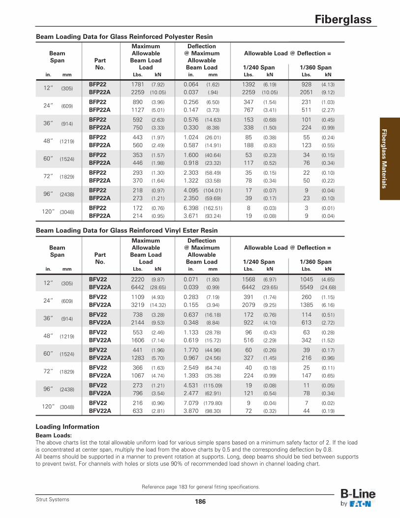
Maximum DeflectionBeam Allowable @ Maximum Allowable Load @ Deflection =Span Part Beam Load Allowable
No. Load Beam Load 1/240 Span 1/360 Spanin. mm Lbs. kN in. mm Lbs. kN Lbs. kN
12” (305)BFP22 1781 (7.92) 0.064 (1.62) 1392 (6.19) 928 (4.13)BFP22A 2259 (10.05) 0.037 (.94) 2259 (10.05) 2051 (9.12)
24” (609)BFP22 890 (3.96) 0.256 (6.50) 347 (1.54) 231 (1.03)BFP22A 1127 (5.01) 0.147 (3.73) 767 (3.41) 511 (2.27)
36” (914)BFP22 592 (2.63) 0.576 (14.63) 153 (0.68) 101 (0.45)BFP22A 750 (3.33) 0.330 (8.38) 338 (1.50) 224 (0.99)
48” (1219)BFP22 443 (1.97) 1.024 (26.01) 85 (0.38) 55 (0.24)BFP22A 560 (2.49) 0.587 (14.91) 188 (0.83) 123 (0.55)
60” (1524)BFP22 353 (1.57) 1.600 (40.64) 53 (0.23) 34 (0.15)BFP22A 446 (1.98) 0.918 (23.32) 117 (0.52) 76 (0.34)
72” (1829)BFP22 293 (1.30) 2.303 (58.49) 35 (0.15) 22 (0.10)BFP22A 370 (1.64) 1.322 (33.58) 78 (0.34) 50 (0.22)
96” (2438)BFP22 218 (0.97) 4.095 (104.01) 17 (0.07) 9 (0.04)BFP22A 273 (1.21) 2.350 (59.69) 39 (0.17) 23 (0.10)
120” (3048)BFP22 172 (0.76) 6.398 (162.51) 8 (0.03) 3 (0.01)BFP22A 214 (0.95) 3.671 (93.24) 19 (0.08) 9 (0.04)
Beam Loading Data for Glass Reinforced Polyester Resin
Beam Loading Data for Glass Reinforced Vinyl Ester Resin
Fiberg
lass Materials
Reference page 183 for general fitting specifications.
Fiberglass
186Strut Systems
Loading InformationBeam Loads:The above charts list the total allowable uniform load for various simple spans based on a minimum safety factor of 2. If the load is concentrated at center span, multiply the load from the above charts by 0.5 and the corresponding deflection by 0.8.All beams should be supported in a manner to prevent rotation at supports. Long, deep beams should be tied between supportsto prevent twist. For channels with holes or slots use 90% of recommended load shown in channel loading chart.
Maximum DeflectionBeam Allowable @ Maximum Allowable Load @ Deflection =Span Part Beam Load Allowable
No. Load Beam Load 1/240 Span 1/360 Spanin. mm Lbs. kN in. mm Lbs. kN Lbs. kN
12” (305)BFV22 2220 (9.87) 0.071 (1.80) 1568 (6.97) 1045 (4.65)BFV22A 6442 (28.65) 0.039 (0.99) 6442 (29.65) 5549 (24.68)
24” (609)BFV22 1109 (4.93) 0.283 (7.19) 391 (1.74) 260 (1.15)BFV22A 3219 (14.32) 0.155 (3.94) 2079 (9.25) 1385 (6.16)
36” (914)BFV22 738 (3.28) 0.637 (16.18) 172 (0.76) 114 (0.51)BFV22A 2144 (9.53) 0.348 (8.84) 922 (4.10) 613 (2.72)
48” (1219)BFV22 553 (2.46) 1.133 (28.78) 96 (0.43) 63 (0.28)BFV22A 1606 (7.14) 0.619 (15.72) 516 (2.29) 342 (1.52)
60” (1524)BFV22 441 (1.96) 1.770 (44.96) 60 (0.26) 39 (0.17)BFV22A 1283 (5.70) 0.967 (24.56) 327 (1.45) 216 (0.96)
72” (1829)BFV22 366 (1.63) 2.549 (64.74) 40 (0.18) 25 (0.11)BFV22A 1067 (4.74) 1.393 (35.38) 224 (0.99) 147 (0.65)
96” (2438)BFV22 273 (1.21) 4.531 (115.09) 19 (0.08) 11 (0.05)BFV22A 796 (3.54) 2.477 (62.91) 121 (0.54) 78 (0.34)
120” (3048)BFV22 216 (0.96) 7.079 (179.80) 9 (0.04) 7 (0.02)BFV22A 633 (2.81) 3.870 (98.30) 72 (0.32) 44 (0.19)

13/16” (20.6)
1” (25.4)
Part No. Material Description Color WeightLbs./ft. kg/m
BFP42* Polyester Resin Solid Back Gray .48 (.71)BFV42* Vinyl Ester Resin Solid Back Beige .48 (.71)BFP42H17/8* Polyester Resin Holes in Back Gray .46 (.68)BFV42H17/8* Vinyl Ester Resin Holes in Back Beige .46 (.68)BFP42SH* Polyester Resin Slots in Back Gray .47 (.70)BFV42SH* Vinyl Ester Resin Slots in Back Beige .47 (.70)
BFP42H17/8BFV42H17/8
9/16” (14.3) holes17/8” (47.6) on centers
BFP42BFV42
Solid Back
BFP42 thru BFV42SH• Channel lengths: 10 Ft. (3.05 m) and 20 Ft. (6.09 m)• Fiberglass strut meets specification of ASTM D-4385 Levels III and IV.
BFP42A
BFV42ASolid Back to Back
BFP42ABFV42A• Channel lengths: 10 Ft. (3.05 m) and 20 Ft. (6.09 m)• Fiberglass strut meets specification of
ASTM D-4385 Levels III and IV.
BFP42SHBFV42SH
9/16” (14.3) x 7/8” (22.2) slots2” (50.8) on centers
15/8” (41.3)
* Insert -10 for 10’-0” (3.05 m) length or -20 for 20’-0” (6.09 m) length
* Insert -10 for 10’-0” (3.05 m) length or -20 for 20’-0” (6.09 m) length
Published design loads on page 187 are based onusage at 70°F (21°C) and must be reduced forcontinuous exposure to higher temperatures. Refer to the chart below for high temperatureapplications.
Field Cutting Sealant Kits
• Seals exposed fibers after field cutting. •• UV resistant •
RSK010 Pint Sealing Kit (473 cm3)includes sealant and brush applicator
2” (50.8)
1” (25.4)
Part No. Material Description Color WeightLbs./ft. kg/m
BFP42A* Polyester Resin Back To Back Gray .85 (1.26)
BFV42A* Vinyl Ester Resin Back To Back Beige .85 (1.26)
13/16” (20.6)
15/8” (41.3)
Fiberglass M
aterials
Reference page 183 for general fitting specifications.
Fiberglass
Strut Systems187
Temperature Design Load Multiplier
75°F (24°C) 100%100°F (38°C) 90%125°F (52°C) 78%150°F (66°C) 68%175°F (79°C) 60%200°F (93°C) 52%
APPROPRIATE PROTECTIVE CLOTHING AND RESPIRATORY PROTECTION DEVICE SHOULD BE WORN WHEN FIELD CUTTING OR GRINDING FIBERGLASS.

Maximum DeflectionBeam Allowable @ Maximum Allowable Load @ Deflection =Span Part Beam Load Allowable
No. Load Beam Load 1/240 Span 1/360 Spanin. mm Lbs. kN in. mm Lbs. kN Lbs. kN
12” (305)BFP42 841 (3.74) 0.104 (2.64) 403 (1.79) 269 (1.19)BFP42A 2325 (10.34) 0.060 (1.52) 1948 (8.66) 1299 (5.78)
24” (609)BFP42 420 (1.87) 0.417 (10.59) 100 (0.44) 66 (0.29)BFP42A 1161 (5.16) 0.239 (6.07) 486 (2.16) 323 (1.43)
36” (914)BFP42 279 (1.24) 0.938 (23.82) 43 (0.19) 29 (0.13)BFP42A 773 (3.44) 0.537 (13.64) 214 (0.95) 142 (0.63)
48” (1219)BFP42 208 (0.92) 1.667 (42.34) 23 (0.10) 15 (0.06)BFP42A 578 (2.57) 0.955 (24.26) 119 (0.53) 78 (0.34)
60” (1524)BFP42 166 (0.74) 2.604 (66.14) 14 (0.06) 8 (0.03)BFP42A 461 (2.05) 1.491 (37.87) 74 (0.33) 48 (0.21)
72” (1829)BFP42 137 (0.61) 3.750 (95.25) 8 (0.03) 5 (0.02)BFP42A 383 (1.70) 2.148 (54.56) 49 (0.22) 31 (0.14)
96” (2438)BFP42 101 (0.45) 6.667 (169.34) 3 (0.01) – –BFP42A 284 (1.26) 3.818 (96.98) 24 (0.10) 14 (0.04)
120” (3048)BFP42 79 (0.35) 10.417 (264.59) – – – –BFP42A 224 (0.99) 5.966 (151.53) 11 (0.05) 5 (0.02)
Loading InformationBeam Loads:The above charts list the total allowable uniform load for various simple spans based on a minimum safety factor of 2. If the load is concentrated at center span, multiply the load from the above charts by 0.5 and the corresponding deflection by 0.8.All beams should be supported in a manner to prevent rotation at supports. Long, deep beams should be tied between supportsto prevent twist. For channels with holes or slots use 90% of recommended load shown in channel loading chart.
Fiberg
lass Materials
Reference page 183 for general fitting specifications.
Fiberglass
188Strut Systems
Beam Loading Data for Glass Reinforced Polyester Resin
Beam Loading Data for Glass Reinforced Vinyl Ester Resin
Maximum DeflectionBeam Allowable @ Maximum Allowable Load @ Deflection =Span Part Beam Load Allowable
No. Load Beam Load 1/240 Span 1/360 Spanin. mm Lbs. kN in. mm Lbs. kN Lbs. kN
12” (305)BFV42 988 (4.39) 0.112 (2.84) 440 (1.96) 293 (1.30)BFV42A 2865 (12.74) 0.063 (1.60) 2278 (10.13) 1518 (6.75)
24” (609)BFV42 493 (2.19) 0.448 (11.38) 109 (0.48) 73 (0.32)BFV42A 1431 (6.36) 0.252 (6.40) 568 (2.52) 378 (1.68)
36” (914)BFV42 328 (1.46) 1.009 (25.63) 48 (0.21) 31 (0.14)BFV42A 953 (4.24) 0.566 (14.37) 251 (1.11) 166 (0.74)
48” (1219)BFV42 245 (1.09) 1.793 (45.54) 26 (0.11) 16 (0.07)BFV42A 713 (3.17) 1.006 (25.55) 139 (0.62) 92 (0.41)
60” (1524)BFV42 195 (0.87) 2.802 (71.17) 15 (0.06) 9 (0.04)BFV42A 569 (2.53) 1.572 (39.93) 87 (0.38) 57 (0.25)
72” (1829)BFV42 162 (0.72) 4.035 (102.49) 9 (0.04) 5 (0.02)BFV42A 473 (2.10) 2.264 (57.50) 58 (0.26) 37 (0.16)
96” (2438)BFV42 120 (0.53) 7.173 (182.19) 3 (0.01) 1 (0.004)BFV42A 351 (1.56) 4.025 (102.23) 29 (0.13) 17 (0.07)
120” (3048)BFV42 94 (0.42) 11.207 (284.66) – – – –BFV42A 278 (1.23) 6.288 (159.71) 14 (0.06) 7 (0.03)

Nominal Thread Design Load Design Load MaximumPart No. Pipe Size Size A B Torque Wt./C
in. mm Lbs. kN Lbs. kN in.-Lbs. N•m Lbs. kg
BFV501-1/2 1/2 (15) 3/8”-16 300 (1.33) 150 (.67) 30 (3.4) 3.5 (1.59)
BFV501-3/4 3/4 (20) 3/8”-16 300 (1.33) 150 (.67) 30 (3.4) 3.9 (1.77)
BFV501-1 1 (25) 3/8”-16 300 (1.33) 150 (.67) 30 (3.4) 4.4 (1.99)
BFV501-11/4 11/4 (32) 3/8”-16 300 (1.33) 150 (.67) 30 (3.4) 4.8 (2.18)
BFV501-11/2 11/2 (40) 3/8”-16 300 (1.33) 150 (.67) 30 (3.4) 5.2 (2.36)
BFV501-2 2 (50) 1/2”-13 600 (2.67) 200 (.89) 60 (6.8) 7.7 (3.49)
BFV501-21/2 21/2 (65) 1/2”-13 600 (2.67) 200 (.89) 60 (6.8) 10.2 (4.63)
BFV501-3 3 (80) 1/2”-13 600 (2.67) 200 (.89) 60 (6.8) 12.6 (5.71)
BFV501-31/2 31/2 (90) 1/2”-13 600 (2.67) 200 (.89) 60 (6.8) 15.1 (6.85)
BFV501-4 4 (100) 1/2”-13 600 (2.67) 200 (.89) 60 (6.8) 17.6 (7.98)
Load A
LoadB
BFV501 Series U-Bolts with Hex Nuts• Design Load Safety Factor of 3• Load A: Straight down loading• Load B: Side loading• Inner surface of U-Bolt is flat to provide additional contact surface area• Material: Glass Reinforced Polyurethane
BF*22IConcrete Inserts• Design Load 300 Lbs (1.47 kN)• Safety Factor of 3• Standard lengths: 6” (152),12” (305), 24” (609),
36” (914), 48” (1219), 60” (1524), 72” (1829), 84” (2133), 96” (2438), 108” (2743) and 120” (3048)
• Available Material:*Insert P for BFP - Polyester Resin channel and tee*Insert V for BFV - Vinyl Ester Resin channel with Polyester Resin tee
• Shipped with removable styrofoam insert
31/8” (79.4)
Length
15/8” (41.3) x 15/8” (41.3)Channel Size
Field Cutting Sealant Kits
• Seals exposed fibers after field cutting •• UV resistant •
RSK010 . . . Pint Sealing Kit (473 cm3)includes sealant and brush applicator
Fiberglass M
aterials
Reference page 183 for general fitting specifications.
Fiberglass
Strut Systems189
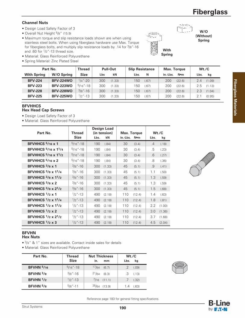
BFVHHCS Hex Head Cap Screws• Design Load Safety Factor of 3• Material: Glass Reinforced Polyurethane
Design LoadPart No. Thread (in tension) Max. Torque Wt./C
Size Lbs. kN in.-Lbs. N•m Lbs. kg
BFVHHCS 5/16 x 1 5/16”-18 190 (.84) 30 (3.4) .4 (.18)
BFVHHCS 5/16 x 11/4 5/16”-18 190 (.84) 30 (3.4) .5 (.23)
BFVHHCS 5/16 x 11/2 5/16”-18 190 (.84) 30 (3.4) .6 (.27)
BFVHHCS 5/16 x 2 5/16”-18 190 (.84) 30 (3.4) .8 (.36)
BFVHHCS 3/8 x 1 3/8”-16 300 (1.33) 45 (5.1) .9 (.41)
BFVHHCS 3/8 x 11/4 3/8”-16 300 (1.33) 45 (5.1) 1.1 (.50)
BFVHHCS 3/8 x 11/2 3/8”-16 300 (1.33) 45 (5.1) 1.3 (.59)
BFVHHCS 3/8 x 2 3/8”-16 300 (1.33) 45 (5.1) 1.3 (.59)
BFVHHCS 3/8 x 21/2 3/8”-16 300 (1.33) 45 (5.1) 1.5 (.68)
BFVHHCS 1/2 x 1 1/2”-13 490 (2.18) 110 (12.4) 1.4 (.63)
BFVHHCS 1/2 x 11/4 1/2”-13 490 (2.18) 110 (12.4) 1.8 (.81)
BFVHHCS 1/2 x 11/2 1/2”-13 490 (2.18) 110 (12.4) 2.2 (1.00)
BFVHHCS 1/2 x 2 1/2”-13 490 (2.18) 110 (12.4) 3.0 (1.36)
BFVHHCS 1/2 x 21/2 1/2”-13 490 (2.18) 110 (12.4) 3.7 (1.68)
BFVHHCS 1/2 x 3 1/2”-13 490 (2.18) 110 (12.4) 4.5 (2.04)
BFVHN Hex Nuts• 3/4” & 1” sizes are available. Contact inside sales for details• Material: Glass Reinforced Polyurethane
Part No. Thread Nut Thickness Wt./CSize in. mm Lbs. kg
BFVHN 5/16 5/16”-18 17/64 (6.7) .2 (.09)
BFVHN 3/8 3/8”-16 21/64 (8.3) .3 (.13)
BFVHN 1/2 1/2”-13 7/16 (11.1) .7 (.32)
BFVHN 5/8 5/8”-11 35/64 (13.9) 1.4 (.63)
Part No. Thread Pull-Out Slip Resistance Max. Torque Wt./C
With Spring W/O Spring Size Lbs kN Lbs. N in.-Lbs. N•m Lbs. kg
BFV-224 BFV-224WO 1/4”-20 300 (1.33) 150 (.67) 200 (22.6) 2.4 (1.09)
BFV-223 BFV-223WO 5/16”-18 300 (1.33) 150 (.67) 200 (22.6) 2.5 (1.13)
BFV-228 BFV-228WO 3/8”-16 300 (1.33) 150 (.67) 200 (22.6) 2.3 (1.04)
BFV-225 BFV-225WO 1/2”-13 300 (1.33) 150 (.67) 200 (22.6) 2.1 (0.95)
WithSpring
W/O(Without)Spring
Channel Nuts• Design Load Safety Factor of 3• Overall Nut Height 5/8” (15.9)• Maximum torque and slip resistance loads shown are when using
stainless steel bolts. When using fiberglass hardware use Max. Torque for fiberglass bolts, and multiply slip resistance loads by .14 for 3/8”-16and .60 for 1/2”-13 thread size.
• Material: Glass Reinforced Polyurethane• Spring Material: Zinc Plated Steel
Fiberg
lass Materials
Reference page 183 for general fitting specifications.
Fiberglass
190Strut Systems
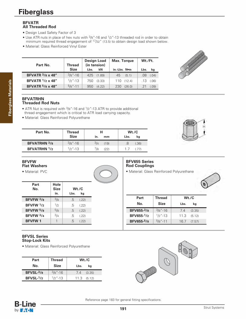
BFVATRHN Threaded Rod Nuts• ATR Nut is required with 3/8”-16 and 1/2”-13 ATR to provide additional
thread engagement which is critical to ATR load carrying capacity.• Material: Glass Reinforced Polyurethane
BFVSL Series Stop-Lock Kits• Material: Glass Reinforced Polyurethane
Part Thread Wt./C
No. Size Lbs. kg
BFVSL-3/8 3/8”-16 7.4 (3.35)
BFVSL-1/2 1/2”-13 11.3 (5.12)
Part No. Thread H Wt./CSize in. mm Lbs. kg
BFVATRHN 3/8 3/8”-16 3/4 (19) .8 (.36)
BFVATRHN 1/2 1/2”-13 7/8 (22) 1.7 (.77)
BFVATRAll Threaded Rod• Design Load Safety Factor of 3• Use ATR nuts in place of hex nuts with 3/8”-16 and 1/2”-13 threaded rod in order to obtain
minimum required thread engagement of 17/32” (13.5) to obtain design load shown below.• Material: Glass Reinforced Vinyl Ester
Design Load Max. Torque Wt./Ft.Part No. Thread (in tension)
Size Lbs. kN in.-Lbs. N•m Lbs. kg
BFVATR 3/8 x 48” 3/8”-16 425 (1.89) 45 (5.1) .08 (.04)
BFVATR 1/2 x 48” 1/2”-13 750 (3.33) 110 (12.4) .13 (.06)
BFVATR 5/8 x 48” 5/8”-11 950 (4.22) 230 (26.0) .21 (.09)
BFVFW Flat Washers• Material: PVC
Part HoleNo. Size Wt./C
in. Lbs. kg
BFVFW 3/8 3/8 .5 (.22)
BFVFW 1/2 1/2 .5 (.22)
BFVFW 5/8 5/8 .5 (.22)
BFVFW 3/4 3/4 .5 (.22)
BFVFW 1 1 .5 (.22)
H
Fiberglass M
aterials
BFV655 Series Rod Couplings• Material: Glass Reinforced Polyurethane
Part Thread Wt./C
No. Size Lbs. kg
BFV655-3/8 3/8”-16 7.4 (3.35)
BFV655-1/2 1/2”-13 11.3 (5.12)
BFV655-5/8 5/8”-11 16.7 (7.57)
Reference page 183 for general fitting specifications.
Fiberglass
Strut Systems191

Nominal Design Load MaximumPart No. Pipe Size Torque
in. mm Lbs. kN in.-Lbs. N•m
BFV2008 1/2 (15) 300 (1.33) 10 (1.13)
BFV2009 3/4 (20) 300 (1.33) 10 (1.13)
BFV2010 1 (25) 300 (1.33) 10 (1.13)
BFV2011 11/4 (32) 300 (1.33) 10 (1.13)
BFV2012 11/2 (40) 300 (1.33) 10 (1.13)
BFV2013 2 (50) 300 (1.33) 10 (1.13)
BFV2014 21/2 (65) 300 (1.33) 10 (1.13)
BFV2015 3 (80) 300 (1.33) 10 (1.13)BFV2016 31/2 (90) 300 (1.33) 10 (1.13)
BFV2017 4 (100) 300 (1.33) 10 (1.13)
BFV2000 SeriesNon-Metallic Pipe Clamps• For rigid and PVC conduit.• Standard hardware includes slotted round head machine
screw and square nut in 316 stainless steel • Design Load Safety Factor of 3• Material: Glass Reinforced PPO• Not recommended for vertical installation without additional Stop-Lock
Kit. Kit includes one square washer, channel nut and hex head cap screw.Order (Stop-Lock Kit on page 191) BFVSL-3/8 for 3/8”-16 hardware or BFVSL-1/2 for 1/2”-13 hardware. Mount kit below clamp when used in vertical strut to prevent clamp slipping.
• If non-metallic hardware is required, add N to the part number. Example: BFV2008N
BFV100 thru BFV300Adjustable Pipe Clamps• Completely Non-Metallic• Adjustable to U.S. & Metric Pipe Diameters• Fits OD Sizes 3/4” (19.0) to 31/2” (88.9)• Easy To Install• No Special Tools Required• Design Load Safety Factor of 3• Material: Glass Reinforced Polyurethane• Not recommended for vertical installation without additional
Stop-Lock Kit. Kit includes one square washer, channel nutand hex head cap screw.Order (Stop-Lock Kit on page 191) BFVSL-3/8 for 3/8”-16 hardware or BFVSL-1/2 for 1/2”-13 hardware. Mount kit below clamp when used in vertical strut to prevent clamp slipping.
Nominal Pipe O.D. Design Max.Part No. Pipe Sizes Range Load Torque
in. mm in. mm Lbs. kN in.-Lbs. N•m
BFV100 1/2 - 11/2 (15- 40) .75 - 1.90 (21.3 - 48.3) 135 (.60) 10 (1.13)
BFV200 11/2 - 2 (40 - 51) 1.90 - 2.37 (48.3 - 60.3) 135 (.60) 36 (4.07)
BFV300 21/2 - 3 (63 - 76) 2.87 - 3.50 (73.0 - 88.9) 145 (.64) 36 (4.07)
Design Load
Design Load
Stop-Lock Kitfor verticalinstallation
Stop-Lock Kitfor verticalinstallation
Fiberg
lass Materials
Reference page 183 for general fitting specifications.
Fiberglass
192Strut Systems
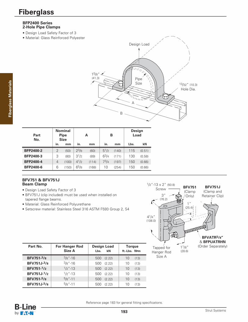
BFP2400 Series 2-Hole Pipe Clamps• Design Load Safety Factor of 3• Material: Glass Reinforced Polyester
BFV751 & BFV751J Beam Clamp• Design Load Safety Factor of 3• BFV751J (clip included) must be used when installed on
tapered flange beams.• Material: Glass Reinforced Polyurethane• Setscrew material: Stainless Steel 316 ASTM F593 Group 2, S4
Part No. For Hanger Rod Design Load TorqueSize A Lbs. kN ft.-Lbs. N•m
BFV751-3/8 3/8”-16 500 (2.22) 10 (13)
BFV751J-3/8 3/8”-16 500 (2.22) 10 (13)
BFV751-1/2 1/2”-13 500 (2.22) 10 (13)
BFV751J-1/2 1/2”-13 500 (2.22) 10 (13)
BFV751-5/8 5/8”-11 500 (2.22) 10 (13)
BFV751J-5/8 5/8”-11 500 (2.22) 10 (13)
41/4” (108.0)
11/8” (28.6)
1” (25.4)
1/2”-13 x 2” (50.8)Screw
Tapped forHanger Rod
Size A
BFV751(ClampOnly)
BFV751J(Clamp and
Retainer Clip)
BFVATR3/8” & BFPUATRHN
(Order Separately)
3” (76.2)
Nominal DesignPart Pipe A B LoadNo. Size
in. mm in. mm in. mm Lbs. kN
BFP2400-2 2 (50) 23/8 (60) 51/2 (140) 115 (0.51)
BFP2400-3 3 (80) 31/2 (89) 63/4 (171) 130 (0.58)
BFP2400-4 4 (100) 41/2 (114) 73/4 (197) 150 (0.66)
BFP2400-6 6 (150) 65/8 (168) 10 (254) 150 (0.66)
15/8” (41.3)
13/32” (10.3)Hole Dia.
B
PipeSize
Design Load
A
Fiberglass M
aterials
Reference page 183 for general fitting specifications.
Fiberglass
Strut Systems193
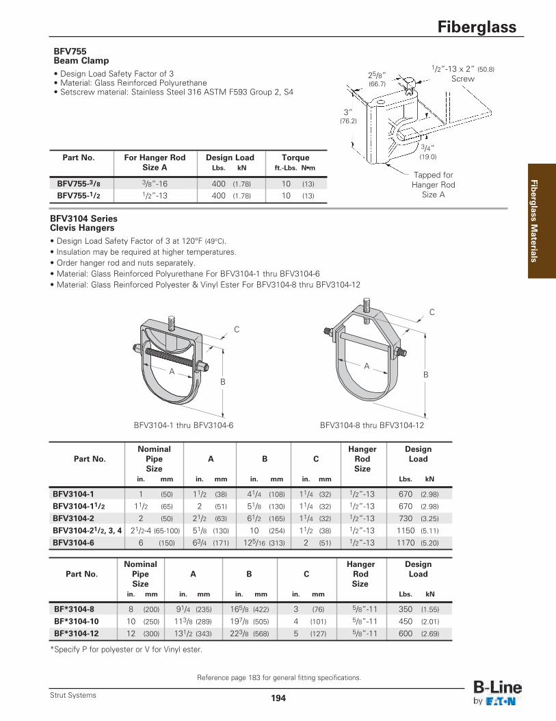
BFV3104 Series Clevis Hangers• Design Load Safety Factor of 3 at 120°F (49°C). • Insulation may be required at higher temperatures.• Order hanger rod and nuts separately.• Material: Glass Reinforced Polyurethane For BFV3104-1 thru BFV3104-6• Material: Glass Reinforced Polyester & Vinyl Ester For BFV3104-8 thru BFV3104-12
Nominal Hanger DesignPart No. Pipe A B C Rod Load
Size Sizein. mm in. mm in. mm in. mm Lbs. kN
BFV3104-1 1 (50) 11/2 (38) 41/4 (108) 11/4 (32) 1/2”-13 670 (2.98)
BFV3104-11/2 11/2 (65) 2 (51) 51/8 (130) 11/4 (32) 1/2”-13 670 (2.98)
BFV3104-2 2 (50) 21/2 (63) 61/2 (165) 11/4 (32) 1/2”-13 730 (3.25)
BFV3104-21/2, 3, 4 21/2-4 (65-100) 51/8 (130) 10 (254) 11/2 (38) 1/2”-13 1150 (5.11)
BFV3104-6 6 (150) 63/4 (171) 125/16 (313) 2 (51) 1/2”-13 1170 (5.20)
Nominal Hanger DesignPart No. Pipe A B C Rod Load
Size Sizein. mm in. mm in. mm in. mm Lbs. kN
BF*3104-8 8 (200) 91/4 (235) 165/8 (422) 3 (76) 5/8”-11 350 (1.55)
BF*3104-10 10 (250) 113/8 (289) 197/8 (505) 4 (101) 5/8”-11 450 (2.01)
BF*3104-12 12 (300) 131/2 (343) 223/8 (568) 5 (127) 5/8”-11 600 (2.69)
BFV3104-1 thru BFV3104-6 BFV3104-8 thru BFV3104-12
AA
BB
C
C
BFV755 Beam Clamp• Design Load Safety Factor of 3• Material: Glass Reinforced Polyurethane• Setscrew material: Stainless Steel 316 ASTM F593 Group 2, S4
Part No. For Hanger Rod Design Load TorqueSize A Lbs. kN ft.-Lbs. N•m
BFV755-3/8 3/8”-16 400 (1.78) 10 (13)
BFV755-1/2 1/2”-13 400 (1.78) 10 (13)
3” (76.2)
3/4” (19.0)
Tapped forHanger Rod
Size A
25/8” (66.7)
1/2”-13 x 2” (50.8)Screw
*Specify P for polyester or V for Vinyl ester.
Fiberg
lass Materials
Reference page 183 for general fitting specifications.
Fiberglass
194Strut Systems

BF*494 Series Brackets 24” (609mm) to 36” (914mm) Long• Design Load Safety Factor of 3 based on uniform loading• MH1 - From Top of Bracket to center of Mounting Hole• MH2 - From Bottom of Bracket to center of Mounting Hole• Material: Glass Reinforced Vinyl Ester or Polyester
DesignPart No. A B Load
in. mm in. mm Lbs. kN
BF*494-24 28 (711) 23 (584) 750 (3.33)
BF*494-30 34 (863) 26 (660) 750 (3.33)
BF*494-36 40 (1016) 29 (736) 750 (3.33)
* Insert P for Glass Reinforced Polyester Resin orV for Glass Reinforced Vinyl Ester Resin
BF*409 Series Brackets 6” (152mm) to 24” (609mm) Long• Design Load Safety Factor of 3 based on uniform loading• MH1 - From Top of Bracket to center of Mounting Hole• MH2 - From Bottom of Bracket to center of Mounting Hole
DesignPart No. A Load
in. mm Lbs. kN
BF*409-6 10 (250) 1400 (6.22)
BF*409-9 13 (330) 1000 (4.45)
BF*409-12 16 (406) 800 (3.56)
BF*409-18 22 (559) 675 (3.00)
BF*409-24 28 (711) 450 (2.00)
* Insert P for Glass Reinforced Polyester Resin orV for Glass Reinforced Vinyl Ester Resin
A
A
B
13/32” (10.3) Dia.Mounting Holes
13/32” (10.3) Dia.Mounting Holes
11/4” (31.7)To Hole
11/4” (31.7)To Hole
11/4” (31.7)To Hole
11/4” (31.7)To Hole
12”(304.8)
Fiberglass M
aterials
Reference page 183 for general fitting specifications.
Fiberglass
Strut Systems195
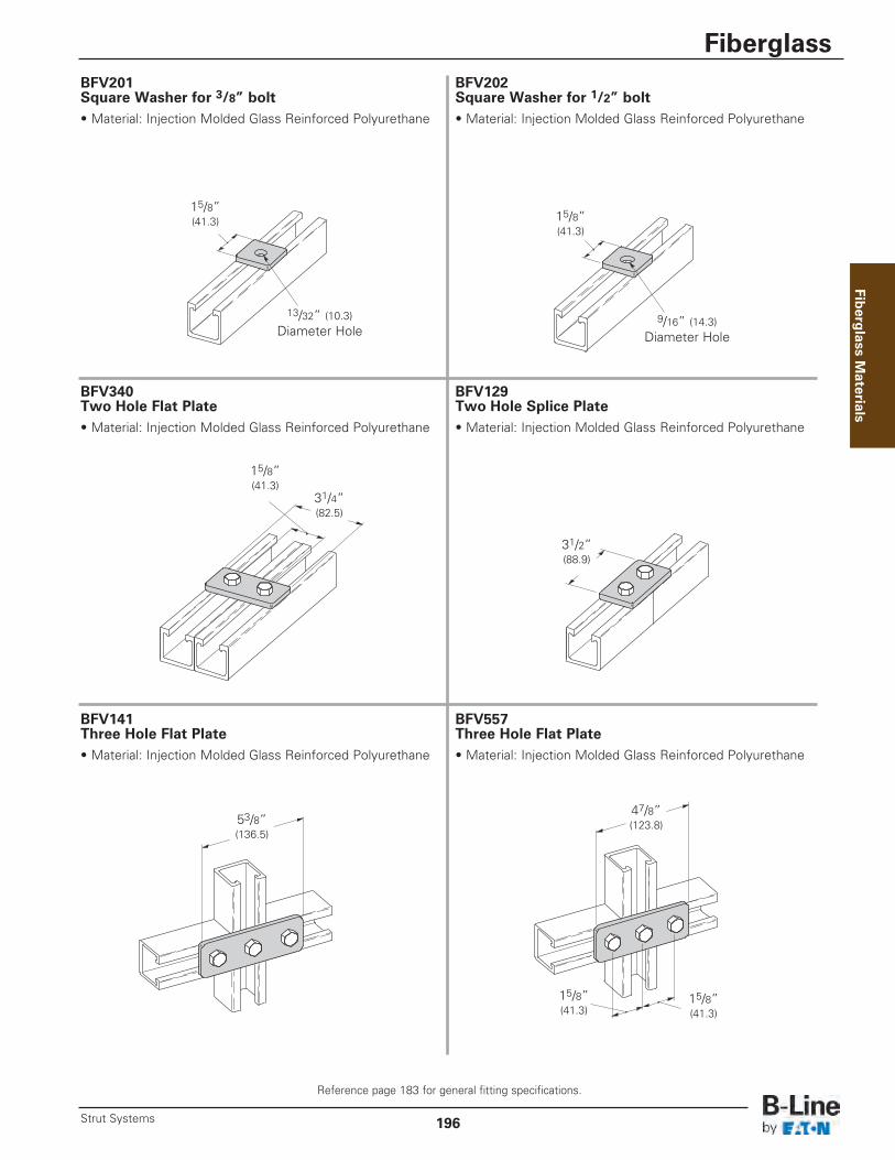
BFV201Square Washer for 3/8” bolt• Material: Injection Molded Glass Reinforced Polyurethane
BFV202Square Washer for 1/2” bolt• Material: Injection Molded Glass Reinforced Polyurethane
BFV141Three Hole Flat Plate• Material: Injection Molded Glass Reinforced Polyurethane
BFV340Two Hole Flat Plate• Material: Injection Molded Glass Reinforced Polyurethane
BFV129Two Hole Splice Plate• Material: Injection Molded Glass Reinforced Polyurethane
BFV557Three Hole Flat Plate• Material: Injection Molded Glass Reinforced Polyurethane
15/8”(41.3)
15/8”(41.3)
15/8”(41.3)
15/8”(41.3)
15/8”(41.3)
13/32” (10.3)Diameter Hole
9/16” (14.3)Diameter Hole
31/2”(88.9)
31/4”(82.5)
53/8”(136.5)
47/8”(123.8)
Fiberg
lass Materials
Reference page 183 for general fitting specifications.
Fiberglass
196Strut Systems

BFV341Four Hole Splice Plate• Material: Injection Molded Glass Reinforced Polyurethane
BFV342Five Hole Flat Plate• Material: Injection Molded Glass Reinforced Polyurethane
BFV132Five Hole Flat Cross Plate• Material: Injection Molded Glass Reinforced Polyurethane
BFV140Three Hole Flat Corner Plate• Material: Injection Molded Glass Reinforced Polyurethane
BFV143Four Hole Flat Corner Plate• Material: Injection Molded Glass Reinforced Polyurethane
BFV133Four Hole Flat Tee Plate• Material: Injection Molded Glass Reinforced Polyurethane
31/2”(88.9)
31/2”(88.9)
53/8”(136.5)
53/8”(136.5)
53/8”(136.5) 53/8”
(136.5)
71/4”(184.1)
91/8”(231.8)
31/2”(88.9)
31/2”(88.9)
Fiberglass M
aterials
Reference page 183 for general fitting specifications.
Fiberglass
Strut Systems197

BFV135Three Hole Flat Gusset Corner Plate• Material: Injection Molded Glass Reinforced Polyurethane
BFV142Four Hole Flat Gusset Corner Plate• Material: Injection Molded Glass Reinforced Polyurethane
BFV532Five Hole Flat Gusset Tee Plate• Material: Injection Molded Glass Reinforced Polyurethane
BFV337Three Hole Flat Gusset Tee Plate• Material: Injection Molded Glass Reinforced Polyurethane
BFV136Four Hole Flat Gusset Tee Plate• Material: Injection Molded Glass Reinforced Polyurethane
BFV334Seven Hole Flat Gusset Cross Plate• Material: Injection Molded Glass Reinforced Polyurethane
31/2”(88.9)
31/2”(88.9)
31/2”(88.9)
31/2”(88.9)
31/2”(88.9)
31/2”(88.9)
53/8”(136.5)
53/8”(136.5)
53/8”(136.5)
53/8”(136.5)
91/8”(231.8)
53/8”(136.5)
Fiberg
lass Materials
Reference page 183 for general fitting specifications.
Fiberglass
198Strut Systems

31/2”(88.9)
31/2”(88.9)
41/8”(104.8)41/8”
(104.8)
BFV101Two Hole 90° Corner Angle• Material: Injection Molded Glass Reinforced Polyurethane
BFV103Three Hole 90° Corner Angle• Material: Injection Molded Glass Reinforced Polyurethane
BFV558Four Hole 90° Corner Angle• Material: Injection Molded Glass Reinforced Polyurethane
BFV104Four Hole 90° Corner Angle• Material: Injection Molded Glass Reinforced Polyurethane
BFV118Four Hole 90° Gussetted Shelf Angle• Material: Injection Molded Glass Reinforced Polyurethane
BFV371-2GThree Hole 90° Gussetted Corner Angle• Material: Injection Molded Glass Reinforced Polyurethane
31/4”(82.5)
15/8”(41.3) 15/8”
(41.3)
4”(101.6)
Three Holes.400” Dia. (10.1)
21/4”(57.1)
15/8”(41.3)
15/8”(41.3)
41/8”(104.8)
25/16”(58.7)
15/8”(41.3)15/8”
(41.3)
Fiberglass M
aterials
Reference page 183 for general fitting specifications.
Fiberglass
Strut Systems199

BFV280SQPost Base for BF*22• Material: Glass Reinforced Polyurethane
BFV281SQPost Base for BF*22A• Material: Glass Reinforced Polyurethane
BFV650Channel Spacer• Spacer I.D. accommodates 3/8" rod or bolts.• Material: Polyurethane
B217PPlastic Closure Strip• Available in 10 Ft. (3.05 m) lengths.• Material: PVC
17/16”(36.5)
5”(127.0)
5”(127.0)
5”(127.0)
3”(76.3)
3”(76.3)
Used when attaching fittings to side walls ofchannel. This channel spacer prevents wallcompression in heavy load conditions.
65/8”(168.3)
5/8”(15.9)
Fiberg
lass Materials
Reference page 183 for general fitting specifications.
Fiberglass
200Strut Systems