FERRITE CORES AND TILES
10
FERRITE CORES AND TILES FERRITE CORES AND TILES - Rev15 - 10/08/2013 The specifications and properties regarding performance above are not guaranteed, and are subject to change without notice due to product improvement and specification change. Please contact us before use. For storage of the products keep them in cool and dry rooms at ambient temperature avoiding high temperatures, humidity, and direct sunlight. All statements, technical information, and recommendations herein are based on tests and are believed to be reliable, but the accuracy and completeness are not guarantee d and are subject to change without notice due to product improvement and specification change. The following is made in lieu of all warranties, expressed or implied, including the implied warranties of marketability and fitness for purpose. Intermark USA’s obligation under this warranty shall be limited to replacement of product that proves to be defective. Before using, user shall determine the suitability of the product for its intended use, and user assumes all risk and liability whatsoever in connection therewith. Intermark USA shall have no liability for any injury, loss or damage arising out of the use of or the inability to use the products. No statement or recommendation not contained herein shall have any force or effect unless in an agreement signed by officers of seller and manufacturer. 1. Shape factor (Se/Le): larger the shape factor, the higher the impedance. For the case of 1 pass through the core, a snug fit, and longer core is recommended as space permits. 2. Adjust the ferrite core positioning to target for antinode placement. 3. Performance can be increased by looping the cable around the core between to 3~5 times. GTFCK Series GTFC Series GRFC Series RFCK2-20 (w/mounting tab) ROUND CABLE CORES: Split Type G Ferrite Core - no nickel and competitively priced NEW! GRFC Series PART NO. A B C D Applicable Cable Diameter (mm) Impedance Ω/100MHz GRFC-3 13.7 13.5 18.0 - 3.0 ~ 4.0 ≥35 GRFC-4 13.7 13.5 27.5 - 3.5 ~ 4.5 ≥75 GRFC-5 18.1 18.4 31.5 35.5 4.5 ~ 5.5 ≥100 GRFC-6 18.1 18.4 31.5 35.5 5.5 ~ 6.5 ≥100 GRFC-7 14.25 15.8 20.0 24.0 7.0 MAX ≥45 GRFC-8 20.1 20.4 31.5 35.5 7.5 ~ 8.5 ≥75 GRFC-9 20.1 20.4 31.5 35.5 8.5 ~ 9.5 ≥75 GRFC-10 26.3 26.4 32.4 37.2 9.5 ~ 10.5 ≥105 GRFC-13 29.1 29.4 31.5 36.3 12.5 ~ 13.5 ≥95 RFC Series RFC-H13 31.7 29.4 41.0 - 12.5 ~ 13.5 ≥170 RFC-20 40.0 40.0 47 - 20 MAX ≥180 RFCK-20 (RFC-20 with mount tab) 40.0 40.0 47 - 20 MAX ≥180 GTFC Series GTFC-16-8-13 22.3 20.1 18.9 - 7.2 MAX ≥ 45 GTFC-16-8-16. 22.3 20.1 21.9 - 7.2 MAX ≥ 55 GTFC-20-10-10 27.1 24.9 16.0 - 8.5 MAX ≥ 40 GTFC-23-11-14 30.5 28.3 20.2 - 10.5 MAX ≥ 55 GTFC-25-15-12 31.1 28.9 17.8 - 13.0 MAX ≥ 40 GTFC-28-16-13 35.1 32.9 18.8 - 14.7 MAX ≥ 50 GTFC-28-16-20 35.1 32.9 25.8 - 14.7 MAX ≥ 70 GTFC-41-27-16 48.2 44.5 19.6 - 26.0 MAX ≥ 50 GTFCK Series GTFCK-16-8-13 32.5 20.4 18.9 22.9 7.2 MAX ≥ 45 GTFCK-16-8-16 32.5 20.4 21.9 25.9 7.2 MAX ≥ 55 GTFCK-20-10-10 37.1 24.9 16.0 20.0 8.5 MAX ≥ 40 GTFCK-23-11-14 40.5 28.3 20.2 24.2 10.5 MAX ≥ 55 GTFCK-25-15-12 41.2 28.9 17.8 21.8 13.0 MAX ≥ 40 GTFCK-28-16-13 45.3 32.9 18.8 22.8 14.7 MAX ≥ 50 GTFCK-28-16-20 45.3 32.9 25.8 29.8 14.7 MAX ≥ 70 GTFCK-41-27-16 51.8 44.5 19.6 - 26.0 MAX ≥ 50 TRCA Series TRCA-20-10-10 22.6 8.2 13.3 - ≥ 50 TRCA-25-15-12 27.3 13.1 15.2 - ≥ 50 TRCA Series
Transcript of FERRITE CORES AND TILES
FERRITE CORES AND TILES
FERRITE CORES AND TILES - Rev15 - 10/08/2013
The specifications and properties regarding performance above are not guaranteed, and are subject to change without notice due to product improvement and specification change. Please contact us before use. For storage of the products keep them in cool and dry rooms at ambient temperature avoiding high temperatures, humidity, and direct sunlight.
All statements, technical information, and recommendations herein are based on tests and are believed to be reliable, but the accuracy and completeness are not guarantee d and are subject to change without notice due to product improvement and specification change. The following is made in lieu of all warranties, expressed or implied, including the implied warranties of marketability and fitness for purpose. Intermark USA’s obligation under this warranty shall be limited to replacement of product that proves to be defective. Before using, user shall determine the suitability of the product for its intended use, and user assumes all risk and liability whatsoever in connection therewith. Intermark USA shall have no liability for any injury, loss or damage arising out of the use of or the inability to use the products. No statement or recommendation not contained herein shall have any force or effect unless in an agreement signed by officers of seller and manufacturer.
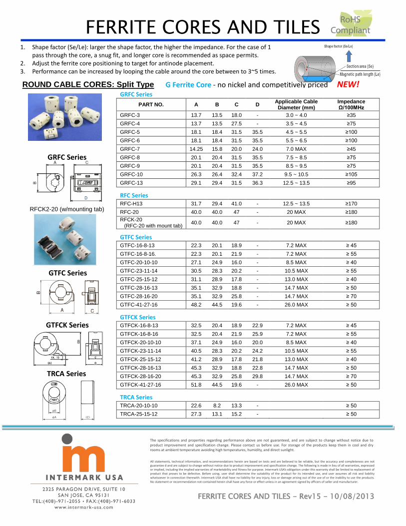
1. Shape factor (Se/Le): larger the shape factor, the higher the impedance. For the case of 1 pass through the core, a snug fit, and longer core is recommended as space permits.
2. Adjust the ferrite core positioning to target for antinode placement. 3. Performance can be increased by looping the cable around the core between to 3~5 times.
GTFCK Series
GTFC Series
GRFC Series
RFCK2-20 (w/mounting tab)
ROUND CABLE CORES: Split Type G Ferrite Core - no nickel and competitively priced NEW! GRFC Series
PART NO. A B C D Applicable Cable Diameter (mm)
Impedance Ω/100MHz
GRFC-3 13.7 13.5 18.0 - 3.0 ~ 4.0 ≥35 GRFC-4 13.7 13.5 27.5 - 3.5 ~ 4.5 ≥75 GRFC-5 18.1 18.4 31.5 35.5 4.5 ~ 5.5 ≥100 GRFC-6 18.1 18.4 31.5 35.5 5.5 ~ 6.5 ≥100 GRFC-7 14.25 15.8 20.0 24.0 7.0 MAX ≥45 GRFC-8 20.1 20.4 31.5 35.5 7.5 ~ 8.5 ≥75 GRFC-9 20.1 20.4 31.5 35.5 8.5 ~ 9.5 ≥75 GRFC-10 26.3 26.4 32.4 37.2 9.5 ~ 10.5 ≥105 GRFC-13 29.1 29.4 31.5 36.3 12.5 ~ 13.5 ≥95
RFC Series RFC-H13 31.7 29.4 41.0 - 12.5 ~ 13.5 ≥170 RFC-20 40.0 40.0 47 - 20 MAX ≥180 RFCK-20
(RFC-20 with mount tab) 40.0 40.0 47 - 20 MAX ≥180
GTFC Series GTFC-16-8-13 22.3 20.1 18.9 - 7.2 MAX ≥ 45 GTFC-16-8-16. 22.3 20.1 21.9 - 7.2 MAX ≥ 55 GTFC-20-10-10 27.1 24.9 16.0 - 8.5 MAX ≥ 40 GTFC-23-11-14 30.5 28.3 20.2 - 10.5 MAX ≥ 55 GTFC-25-15-12 31.1 28.9 17.8 - 13.0 MAX ≥ 40 GTFC-28-16-13 35.1 32.9 18.8 - 14.7 MAX ≥ 50 GTFC-28-16-20 35.1 32.9 25.8 - 14.7 MAX ≥ 70 GTFC-41-27-16 48.2 44.5 19.6 - 26.0 MAX ≥ 50
GTFCK Series GTFCK-16-8-13 32.5 20.4 18.9 22.9 7.2 MAX ≥ 45 GTFCK-16-8-16 32.5 20.4 21.9 25.9 7.2 MAX ≥ 55 GTFCK-20-10-10 37.1 24.9 16.0 20.0 8.5 MAX ≥ 40 GTFCK-23-11-14 40.5 28.3 20.2 24.2 10.5 MAX ≥ 55 GTFCK-25-15-12 41.2 28.9 17.8 21.8 13.0 MAX ≥ 40 GTFCK-28-16-13 45.3 32.9 18.8 22.8 14.7 MAX ≥ 50 GTFCK-28-16-20 45.3 32.9 25.8 29.8 14.7 MAX ≥ 70 GTFCK-41-27-16 51.8 44.5 19.6 - 26.0 MAX ≥ 50
TRCA Series TRCA-20-10-10 22.6 8.2 13.3 - ≥ 50 TRCA-25-15-12 27.3 13.1 15.2 - ≥ 50
TRCA Series
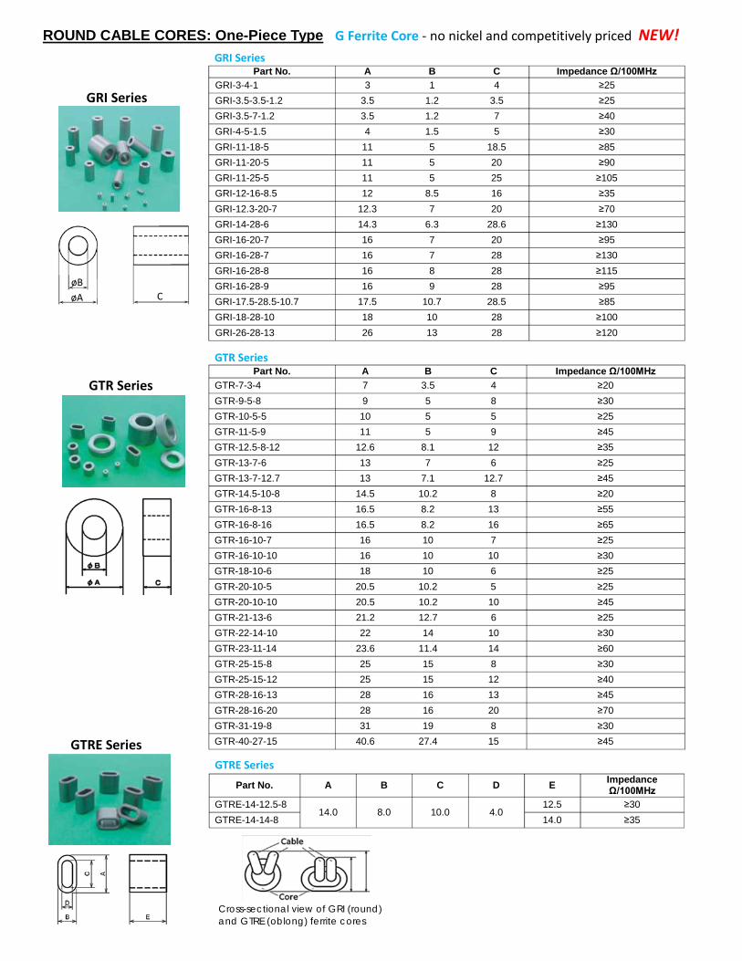
GTR Series
GTR Series Part No. A B C Impedance Ω/100MHz
GTR-7-3-4 7 3.5 4 ≥20 GTR-9-5-8 9 5 8 ≥30 GTR-10-5-5 10 5 5 ≥25 GTR-11-5-9 11 5 9 ≥45 GTR-12.5-8-12 12.6 8.1 12 ≥35 GTR-13-7-6 13 7 6 ≥25 GTR-13-7-12.7 13 7.1 12.7 ≥45 GTR-14.5-10-8 14.5 10.2 8 ≥20 GTR-16-8-13 16.5 8.2 13 ≥55 GTR-16-8-16 16.5 8.2 16 ≥65 GTR-16-10-7 16 10 7 ≥25 GTR-16-10-10 16 10 10 ≥30 GTR-18-10-6 18 10 6 ≥25 GTR-20-10-5 20.5 10.2 5 ≥25 GTR-20-10-10 20.5 10.2 10 ≥45 GTR-21-13-6 21.2 12.7 6 ≥25 GTR-22-14-10 22 14 10 ≥30 GTR-23-11-14 23.6 11.4 14 ≥60 GTR-25-15-8 25 15 8 ≥30 GTR-25-15-12 25 15 12 ≥40 GTR-28-16-13 28 16 13 ≥45 GTR-28-16-20 28 16 20 ≥70 GTR-31-19-8 31 19 8 ≥30 GTR-40-27-15 40.6 27.4 15 ≥45
Cross-sectional view of GRI (round) and GTRE (oblong) ferrite cores
GTRE Series
GTRE Series
Part No. A B C D E Impedance Ω/100MHz
GTRE-14-12.5-8 14.0 8.0 10.0 4.0
12.5 ≥30 GTRE-14-14-8 14.0 ≥35
GRI Series
øA øB
C
ROUND CABLE CORES: One-Piece Type G Ferrite Core - no nickel and competitively priced NEW! GRI Series
Part No. A B C Impedance Ω/100MHz GRI-3-4-1 3 1 4 ≥25 GRI-3.5-3.5-1.2 3.5 1.2 3.5 ≥25 GRI-3.5-7-1.2 3.5 1.2 7 ≥40 GRI-4-5-1.5 4 1.5 5 ≥30 GRI-11-18-5 11 5 18.5 ≥85 GRI-11-20-5 11 5 20 ≥90 GRI-11-25-5 11 5 25 ≥105 GRI-12-16-8.5 12 8.5 16 ≥35 GRI-12.3-20-7 12.3 7 20 ≥70 GRI-14-28-6 14.3 6.3 28.6 ≥130 GRI-16-20-7 16 7 20 ≥95 GRI-16-28-7 16 7 28 ≥130 GRI-16-28-8 16 8 28 ≥115 GRI-16-28-9 16 9 28 ≥95 GRI-17.5-28.5-10.7 17.5 10.7 28.5 ≥85 GRI-18-28-10 18 10 28 ≥100 GRI-26-28-13 26 13 28 ≥120

TRMH – Low frequency, high µ ferrite cores Part No. A B C Impedance Ω/1MHz
TRMH-16-8-16E 16.8 7.3 16.7 ≥18 TRMH-20-10-10E 20.9 9.3 10.8 ≥11 TRMH-25-15-12E 25.8 14.2 12.7 ≥9 TRMH-31-20-15E 32.0 19.1 15.8 ≥9 TRMH-38-19-13E 39.0 18.1 13.8 ≥11 TRMH-47-27-15E 48.2 26.1 15.8 ≥10
-High impedance at less than 1MHz. -Increased impedance can be obtained by several turns. -Suitable for conducted emissions for the KHz ranges.
Part No. A B C Impedance Ω/10MHz (2 turns)
TRM-16-8-16E-WE 17.0 7.1 16.9 ≥70 TRM-20-10-10E-WE 21.0 9.1 10.9 ≥35 TRM-25-15-12E-WE 26.0 14.1 12.9 ≥35 TRM-31-20-15E-WE 32.1 19.0 15.9 ≥30 TRM-38-19-13E-WE 39.2 17.9 14.0 ≥35 TRM-47-27-15E-WE 46.5 25.7 16.3 ≥25
-High impedance noise filters for low frequency. -Looped cable around the core increases effectiveness by 102
TRM – cores for low frequency range Low Frequency Core
TRCB – Low frequency ferrite core with plastic casing NEW!
-Plastic casing prevents ferrite core from cracking and chipping -Suitable for conducted emission from KHz to lower MHz range
Part No. A B C Impedance Ω/10MHz
TRCB-19-10-10 20 8.1 (11.7) ≥ 11 TRCB-25-15-12 26.7 13.3 (13.5) ≥ 8 TRCB-38-19-13 40.5 16.6 (15.1) ≥ 7
Noise Attenuation Effectiveness

MRFC – ferrite clamp for low frequency range NEW!
-Aimed to suppress low frequency noise between 150KHz to 30MHz. -Plastic screw mounting option available -Operating temperature: -40°C ~85°C -UL94V-0-rated housing
Part No. Part No. (screw mount option) A B C D Applicable
cable diameter Impedance Ω/10MHz
MRFC-8 - 20.1 20.4 31.5 35.5 8.5 (MAX)
≥20 MRFC-13 MRFCK-13 29.1 33.05 32.3 37.1 13.5 (MAX)
MRFC-20 MRFCK2-20 40.3 40 47 53.5 20.0 (MAX)
Noise Attenuation Effectiveness
RFC-*MA – Low frequency, high µ ferrite cores -Aimed to suppress low frequency noise generated by engine control units (ECU), inverters, and motors. -Split type with plastic casing -Operating Temperature: -40°C ~ 125°C -Casing has a designated area for placing a plastic cable tie -UL-94V-2 rated
Part No. A B C Applicable Cable Diameter
Impedance Ω/10MHz
RFC-8MA 20.6 19.8 34.0 8.5 (MAX)
≥20 RFC-13MA 29.6 28.4 34.0 12.5~13.5
RFC-20MA 40.0 40.0 47.0 20 (MAX)
Screw mount option
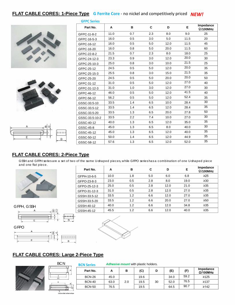
FLAT CABLE CORES: 1-Piece Type GFPC Series
Part No. A B C D E Impedance Ω/100MHz
GFPC-11-8-2 11.0 0.7 2.3 8.0 9.0 25
GFPC-16-5-3 16.0 0.5 3.0 5.0 11.5 20
GFPC-16-12 16.0 0.5 5.0 12.0 11.5 45
GFPC-16-20 16.0 0.8 5.0 20.0 11.5 60
GFPC-22-8-2 21.5 0.7 2.3 8.0 18.0 25
GFPC-24-12-3 23.3 0.9 3.0 12.0 20.0 30
GFPC-25-10-3 25.0 0.8 3.0 10.0 21.5 25
GFPC-25-12 24.5 0.5 5.0 12.0 20.0 35
GFPC-25-15-3 25.5 0.8 3.0 15.0 21.5 35
GFPC-25-20 24.5 0.5 5.0 20.0 20.0 50
GFPC-31-12 31.0 0.5 5.0 12.0 27.0 40
GFPC-31-12-3 31.0 1.0 3.0 12.0 27.0 30
GFPC-46-12 46.0 0.5 5.0 12.0 41.5 40
GFPC-56-12 56.2 0.5 5.0 12.0 52.4 35
GSSC-33.5-10 33.5 1.4 6.5 10.0 28.4 30
GSSC-33.5-12 33.5 1.4 6.5 12.0 28.4 35
GSSC-33.5-20 33.5 1.3 6.5 20.0 27.8 50
GSSC-33.5-10-2 33.5 2.2 7.4 10.0 27.0 30
GSSC-40-12 40.0 1.3 6.5 12.0 35.0 35
GSSC-45-8 45.0 1.3 6.5 8.0 40.0 30
GSSC-45-12 45.0 1.3 6.5 12.0 40.0 35
GSSC-50-12 50.0 1.4 6.5 12.0 44.9 35
GSSC-58-12 57.6 1.3 6.5 12.0 52.0 35
NEW! G Ferrite Core - no nickel and competitively priced
FLAT CABLE CORES: 2-Piece Type GSSH and GFPH series are a set of two of the same U-shaped pieces, while GFPO series has a combination of one U-shaped piece
and one flat piece.
GFPH, GSSH
GFPO
Part No. A B C D E Impedance Ω/100MHz
GFPH-10-6-5 10.0 1.8 5.0 6.0 6.8 ≥25
GFPO-23-8-3 23.0 0.5 2.8 8.0 19.0 ≥30
GFPO-25-12-3 25.0 0.5 2.8 12.0 21.0 ≥35
GFPO-31-12-3 31.0 0.5 2.8 12.0 27.0 ≥35
GSSH-33.5-12 33.5 1.2 6.6 12.0 27.0 ≥35
GSSH-33.5-20 33.5 1.2 6.6 20.0 27.0 ≥50
GSSH-40-12 40.0 1.2 6.6 12.0 34.8 ≥35
GSSH-45-12 45.5 1.2 6.6 12.0 40.0 ≥35
BCN
FLAT CABLE CORES: Large 2-Piece Type
BCN Series Adhesive mount with plastic holders.
Part No. A B (C) D (E) (F) Impedance Ω/100MHz
BCN-26 45.0 2.0
19.6 30
34.0 59.2 ≥125 BCN-40 63.0 19.5 52.0 76.5 ≥137 BCN-50 76.5 19.5 64.5 90.7 ≥142
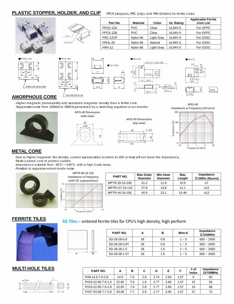
AMORPHOUS CORE -Higher magnetic permeability and saturated magnetic density than a ferrite core. -Suppresses noise from 150KHz to 30MHz generated by a switching regulator or an inverter.
AF01-40 Impedance vs Frequency (10 turns)
PART NO. A B W/m·K Impedance Ω/100MHz
SD-28-28-0.8 28 0.8 1 ~ 5 600 ~ 2000 SD-28-28-0.8T 28 0.8 1 ~ 5 600 ~ 2000 SD-28-28-1.5 28 1.5 1 ~ 5 600 ~ 2000 SD-28-28-1.5T 28 1.5 1 ~ 5 600 ~ 2000
FERRITE TILES SD Tiles – sintered ferrite tiles for CPU’s high density, high perform
MULTI HOLE TILES
PART NO. A B C D E F # of holes
Impedance Ω/100MHz
FH9-14.5-7.6-2.8 14.5 7.6 2.8 2.74 2.84 1.57 9 65 FH15-22.65-7.6-1.6 22.65 7.6 1.6 2.77 2.84 1.57 15 55 FH15-22.65-7.6-2.8 22.65 7.6 2.8 2.77 2.84 1.57 15 68 FH37-53.08-7.7-2.8 53.08 7.7 2.8 2.77 2.84 1.57 37 72
Part No. Material Color UL Rating Applicable Ferrite
Core List FPCK-12A PVC Clear UL94V-0 For GFPC FPCK-12B PVC Clear UL94V-0 For GFPC FRC-12CP Nylon 66 Light Gray UL94V-0 For GSSC FRHL-20 Nylon 66 Natural UL94V-2 For GSSC FRH-12 Nylon 66 Light Gray UL94V-0 For GSSC
PLASTIC STOPPER, HOLDER, AND CLIP FPCK (stopper), FRC (clip), and FRH (holder) for ferrite cores
AF01-40 Dimensions (side view)
AF01-40 Dimensions (top view)
PART NO. Max Outer Diameter
Min Inner Diameter
Max Length
Impedance Ω/1MHz (5turns)
MPTR-20-13-10E 21.2 11.8 10.9 ≥7 MPTR=27-15-11E 27.8 13.8 12.1 ≥12 MPTR-40-24-15E 40.9 23.1 15.48 ≥12
METAL CORE -Due to higher magnetic flux density, current superposition (current at 20A or less) will not lower the impedance. -Resin-coated core to protect cables. -Impedance is stable from -40°C~+140°C, with a high Curie temp. -Possible to suppress normal mode noise.
MPTR-40-24-15E Impedance vs Frequency (with DC superposition)

GRI Impedance Graphs
GTRE Impedance Graphs
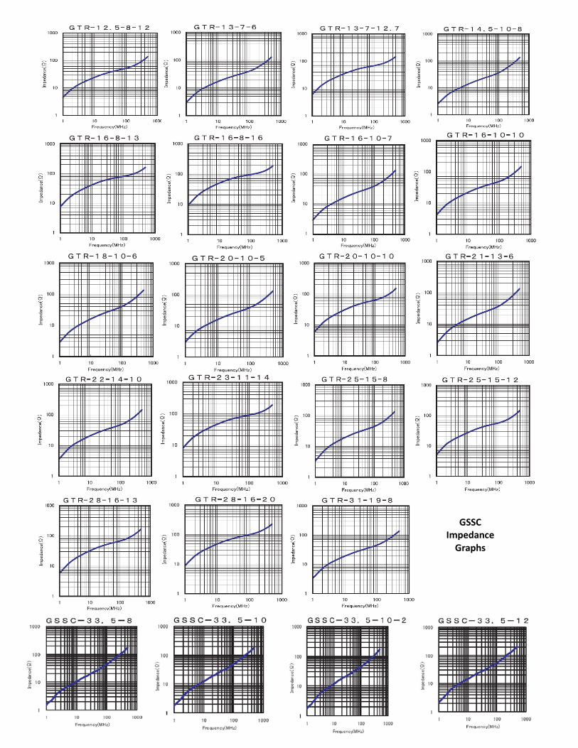
GSSC Impedance
Graphs
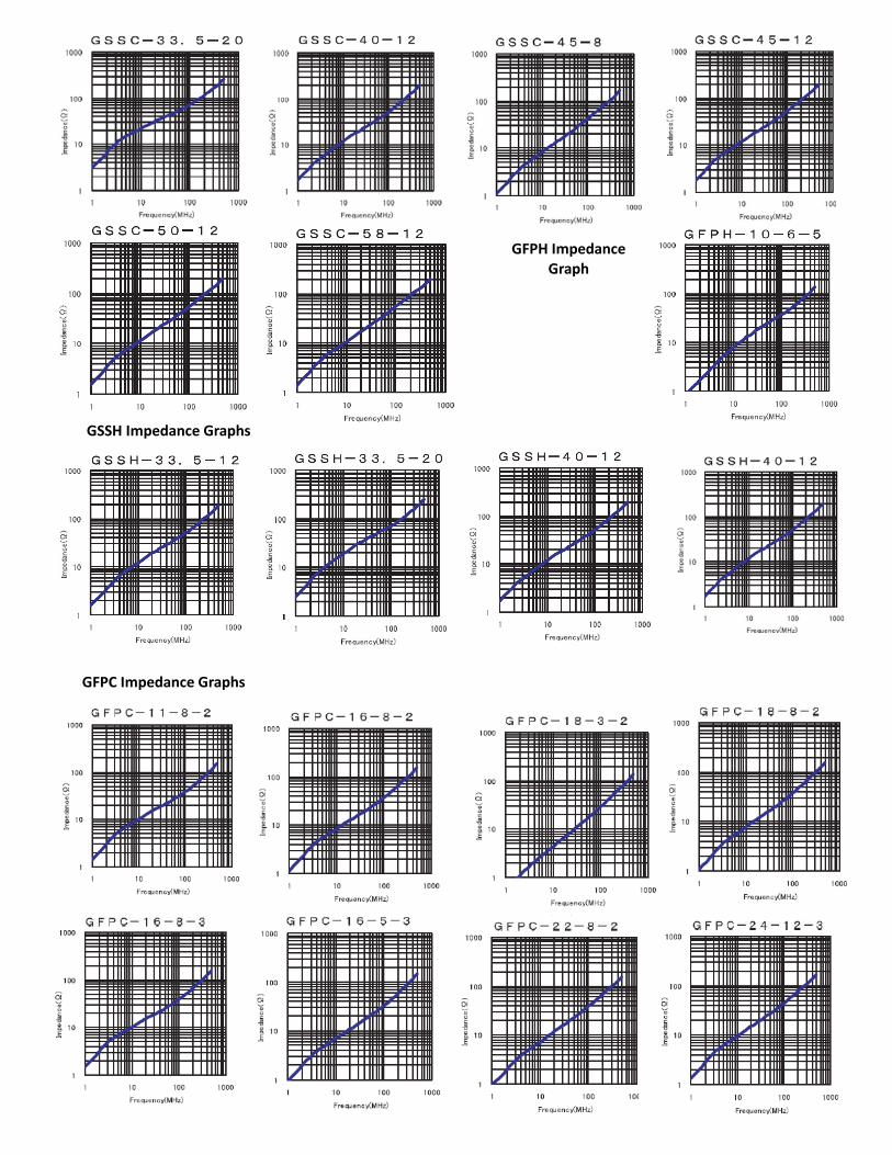
GFPH Impedance Graph
GSSH Impedance Graphs
GFPC Impedance Graphs

GFPO Impedance Graphs
GRFC Impedance Graphs
GRFC-8 GRFC-9
GRFC-5
GRFC-6
GRFC-13