
FENIX – user’s manual - rc-electronics.eu
48
FenixS User’s manual for advance and basic version version 1.0 RC Electronics d.o.o. September 2021
Transcript of FENIX – user’s manual - rc-electronics.eu

FenixSUser’s manual for advance and basic version
version 1.0
RC Electronics d.o.o.
September 2021
FenixS– user’s manual Document Revision: 1.0September 2021
Contact Information
Publisher and producer:
RC Electronics d.o.o.Otemna 1c3201 Šmartno v Rožni doliniSlovenia
Email: [email protected]
1

FenixS– user’s manual Document Revision: 1.0September 2021
Revision History
The following table shows full description of changes made in this document.
DATE DESCRIPTIONOctober 2021 - Initial release of document
2
FenixS– user’s manual Document Revision: 1.0September 2021
Contents1 Introduction..............................................................................................................................................6
1.1 Version differences...........................................................................................................................7
1.2 Reserves all rights.............................................................................................................................8
2 Basic operation.........................................................................................................................................8
2.1 Powering up......................................................................................................................................8
2.2 Front view.........................................................................................................................................9
2.3 User interface.................................................................................................................................10
2.3.1 Rotary knob............................................................................................................................10
2.4 Software update.............................................................................................................................10
2.5 Device shutdown............................................................................................................................11
2.5.1 Loss of main power during flight............................................................................................11
3 Page overview.........................................................................................................................................11
3.1 Main page.......................................................................................................................................12
3.1.1 Digital numeric navigation information..................................................................................13
3.1.2 Flight mode.............................................................................................................................14
3.1.3 Needle unit’s...........................................................................................................................14
3.1.4 Wind and connectivity status.................................................................................................14
3.1.5 Battery status..........................................................................................................................15
3.1.6 Navbox subpage.....................................................................................................................15
3.1.7 Main page sub-menu..............................................................................................................18
3.2 Setup page......................................................................................................................................21
3.3 Settings...........................................................................................................................................22
3.3.1 Pilot........................................................................................................................................22
3.3.2 Vario /SC.................................................................................................................................23
3.3.3 Units.......................................................................................................................................24
3.3.4 Pages......................................................................................................................................25
3.3.5 Voice.......................................................................................................................................26
3
FenixS– user’s manual Document Revision: 1.0September 2021
3.3.6 Glider......................................................................................................................................27
3.3.7 Data port.................................................................................................................................28
3.3.8 Localization.............................................................................................................................29
3.3.9 Info.........................................................................................................................................29
3.3.10 Password..............................................................................................................................30
4 Additional FenixS advance version pages...............................................................................................31
4.1 Thermal assistant page...................................................................................................................31
4.2 Flarm radar page.............................................................................................................................33
4.3 Take-off info page...........................................................................................................................35
4.4 GPS info page..................................................................................................................................36
4.5 Logbook page..................................................................................................................................37
4.6 Flight statistic info page..................................................................................................................38
4.7 Warnings.........................................................................................................................................39
5 Rear of unit.............................................................................................................................................40
5.1 Data port pinout.............................................................................................................................41
6 Bluetooth connectivity............................................................................................................................42
6.1 Pairing.............................................................................................................................................42
6.2 Supported data transfers................................................................................................................42
7 Physical properties..................................................................................................................................43
7.1 Electrical properties........................................................................................................................43
8 Installation of the unit............................................................................................................................44
8.1 Mechanical installation...................................................................................................................44
8.2 Pneumatic connections...................................................................................................................44
9 Flight Recorder.......................................................................................................................................44
9.1 Start and stop of flight recording....................................................................................................45
10 Flying with FenixS.................................................................................................................................46
10.1 Before take-off..............................................................................................................................46
10.1.1 Set Elevation.........................................................................................................................46
4

FenixS– user’s manual Document Revision: 1.0September 2021
10.1.2 Set QNH................................................................................................................................46
10.2 During flight..................................................................................................................................46
10.2.1 Set QNH................................................................................................................................46
10.2.2 Wind calculation...................................................................................................................46
10.2.3 Influence of wind in final glide..............................................................................................47
10.3 After landing.................................................................................................................................47
5

FenixS– user’s manual Document Revision: 1.0September 2021
1 Introduction
The FenixS is a digital vario-navigation unit. It features round “2.1”inch display which is fullyvisible during direct sunlight conditions.
Smart user interaction with the FenixS unit requires only one rotary knobs. With a built-inmulti-language voice module, the FenixS offers the pilot voice warnings, alerts, GPS Info,thermal assistant, Flarm visual support, gliders data base and lot's more.
Depending on, what features the pilot requires in the unit, it can choose between basic andadvance version of the unit.
Below is the short list of the FenixS functionality:
Display of GPS info Internal beeper for Flarm warnings Integrated voice module Single rotary-push knobs for user interface Two data ports for 3rd party devices (FLARM, Wireless module...) Side facing micro SD card port for updates Internal rechargeable battery for short time power supply backup as an option Vario information over TE probe connection Speed to fly function Final glide calculator Internal glider database Thermal assistant Logbook Wind calculation Multi language support
6
NOTE
FenixS is not IGC certified device.

FenixS– user’s manual Document Revision: 1.0September 2021
1.1 Version differences
The following table will show supported features between FenixS versions.
FUNCTION BASIC ADVANCE
Vario needle YES YES
Vario sound YES YES
Settable navbox on the main page YES YES
Wind indicator NO YES
FG calculator NO YES, needs external GPS source
SC tone and arc NO NO
Setup menu YES YES
Volume control YES – directly on knob YES – via quick menu
MC/Ballast/Bugs set NO YES – via quick menu
Speed to flay calculator NO YES
Thermal Assistant NO YES, needs external GPS source
Flarm radar + warnings NO YES, needs external Flarm unit
TP navigation NOYES – to take-off position. External
GPS source is needed
APT navigation NO NO
TSK navigation NO NO
Logbook / Statistic NO YES
GPS info page NO YES
Init screen Yes – elevation + QNH Yes – elevation + QNH
Voice announcements NO YES
Data input Bluetooth module Bluetooth module + external GPS /
FLARM unit
7
FenixS– user’s manual Document Revision: 1.0September 2021
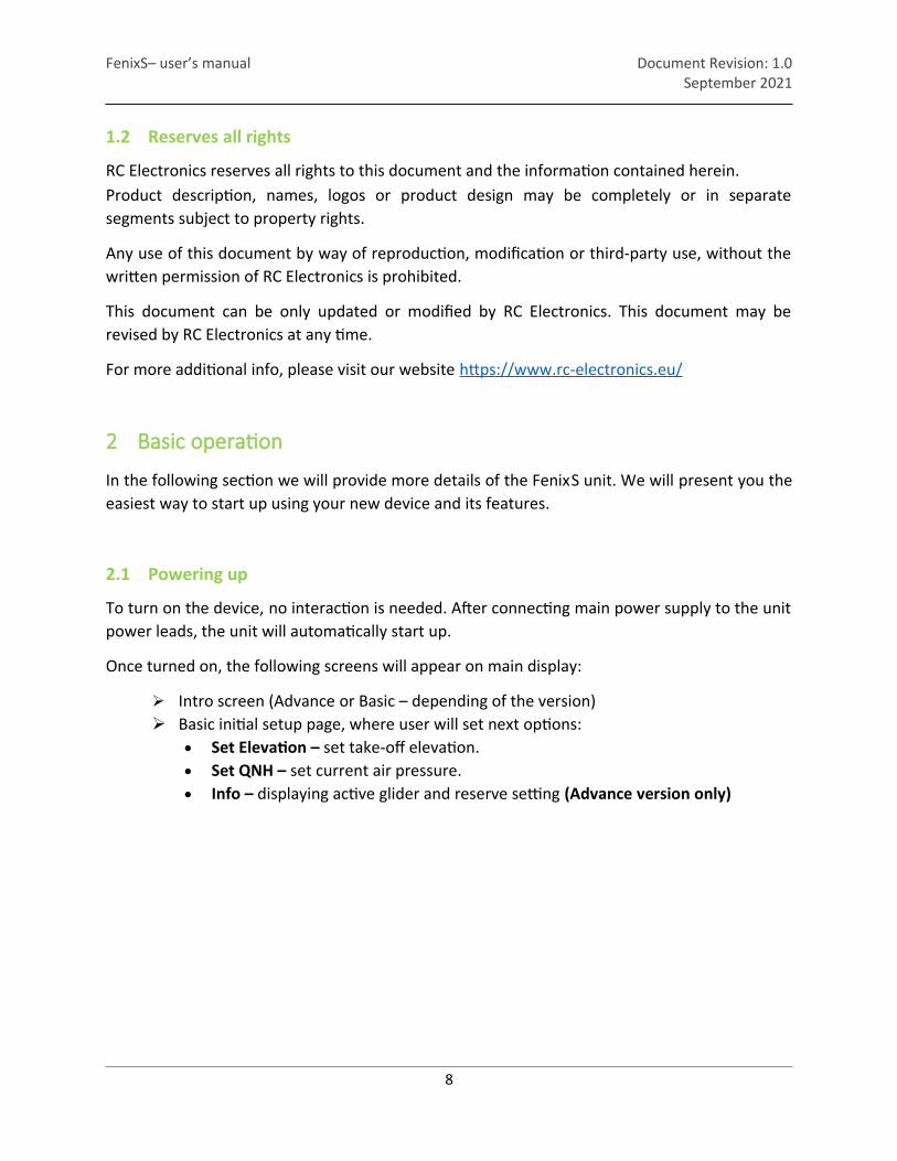
1.2 Reserves all rights
RC Electronics reserves all rights to this document and the information contained herein.Product description, names, logos or product design may be completely or in separatesegments subject to property rights.
Any use of this document by way of reproduction, modification or third-party use, without thewritten permission of RC Electronics is prohibited.
This document can be only updated or modified by RC Electronics. This document may berevised by RC Electronics at any time.
For more additional info, please visit our website https://www.rc-electronics.eu/
2 Basic operation
In the following section we will provide more details of the FenixS unit. We will present you theeasiest way to start up using your new device and its features.
2.1 Powering up
To turn on the device, no interaction is needed. After connecting main power supply to the unitpower leads, the unit will automatically start up.
Once turned on, the following screens will appear on main display:
Intro screen (Advance or Basic – depending of the version) Basic initial setup page, where user will set next options:
Set Elevation – set take-off elevation. Set QNH – set current air pressure. Info – displaying active glider and reserve setting (Advance version only)
8

FenixS– user’s manual Document Revision: 1.0September 2021
2.2 Front view
Figure 1: Reference front view of device (FenixS intro screen)
2
1
3
1 – Main round screen 2 – Device version 3 – Rotary knob with push function
9
FenixS– user’s manual Document Revision: 1.0September 2021
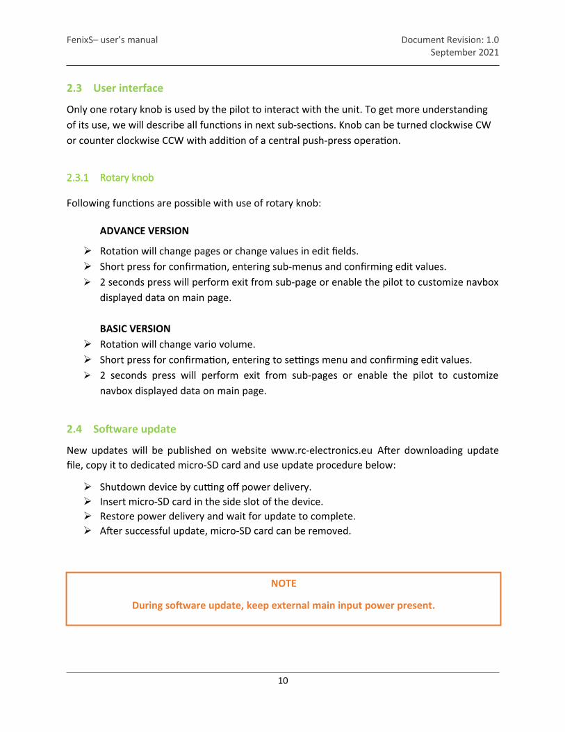
2.3 User interface
Only one rotary knob is used by the pilot to interact with the unit. To get more understanding of its use, we will describe all functions in next sub-sections. Knob can be turned clockwise CW or counter clockwise CCW with addition of a central push-press operation.
2.3.1 Rotary knob
Following functions are possible with use of rotary knob:
ADVANCE VERSION
Rotation will change pages or change values in edit fields. Short press for confirmation, entering sub-menus and confirming edit values. 2 seconds press will perform exit from sub-page or enable the pilot to customize navbox
displayed data on main page.
BASIC VERSION Rotation will change vario volume. Short press for confirmation, entering to settings menu and confirming edit values. 2 seconds press will perform exit from sub-pages or enable the pilot to customize
navbox displayed data on main page.
2.4 Software update
New updates will be published on website www.rc-electronics.eu After downloading updatefile, copy it to dedicated micro-SD card and use update procedure below:
Shutdown device by cutting off power delivery. Insert micro-SD card in the side slot of the device. Restore power delivery and wait for update to complete. After successful update, micro-SD card can be removed.
10
NOTE
During software update, keep external main input power present.
FenixS– user’s manual Document Revision: 1.0September 2021
2.5 Device shutdown
When main supply voltage is turned off, unit will turn off automatically.
2.5.1 Loss of main power during flight
Short interruption of main power can accrue during the flight when pilot switches from primary to
secondary battery. In that time the FenixS unit may turn off, if it doesn’t have internal backup battery (as
an option). If internal battery in installed, then unit will continue with its operation. Internal battery can
maintain all FenixS functions for additional 30min.
3 Page overview
Each page was designed in such a way as to give best user experience and to be clear to read display.
In the unit, displayed pages are selected / changed with rotation of rotary knob. Some pagesalso have sub-menus. To access sub-menu, use short press on rotary knob. After finishcustomization in the sub-menu, simple long press on rotary knob will perform exit. Sub-menucan also be exited by or selection of “Exit” option.
11
FenixS– user’s manual Document Revision: 1.0September 2021
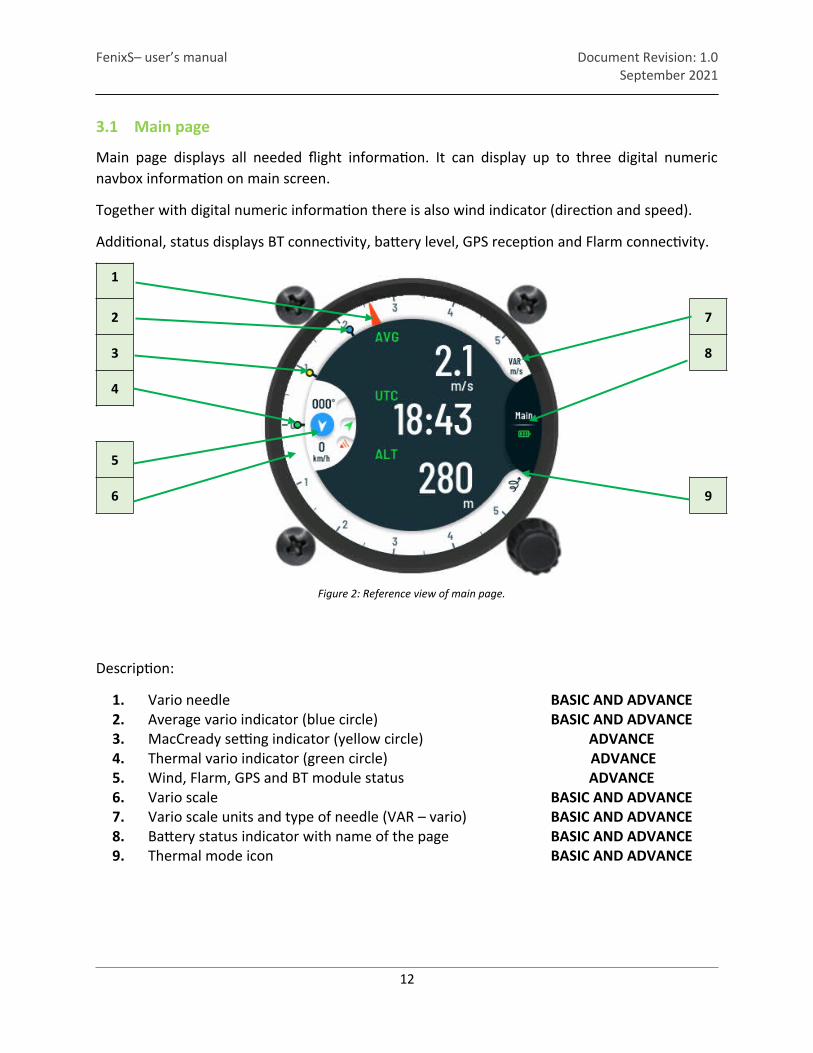
3.1 Main page
Main page displays all needed flight information. It can display up to three digital numericnavbox information on main screen.
Together with digital numeric information there is also wind indicator (direction and speed).
Additional, status displays BT connectivity, battery level, GPS reception and Flarm connectivity.
1
Figure 2: Reference view of main page.
2 7
3 8
4
5
6 9
Description:
1. Vario needle BASIC AND ADVANCE2. Average vario indicator (blue circle) BASIC AND ADVANCE3. MacCready setting indicator (yellow circle) ADVANCE4. Thermal vario indicator (green circle) ADVANCE5. Wind, Flarm, GPS and BT module status ADVANCE6. Vario scale BASIC AND ADVANCE7. Vario scale units and type of needle (VAR – vario) BASIC AND ADVANCE8. Battery status indicator with name of the page BASIC AND ADVANCE9. Thermal mode icon BASIC AND ADVANCE
12

FenixS– user’s manual Document Revision: 1.0September 2021
3.1.1 Digital numeric navigation information
Central view area of the main screen is used to display digital numeric information. The pilotcan set up to three digital numeric values at the same time on the main screen.
13
Figure 3: Displaying one information on the screen.
Figure 4: Displaying two information's on the screen. Figure 5: Displaying three information's on the screen.

FenixS– user’s manual Document Revision: 1.0September 2021
3.1.2 Flight mode
The status icon at bottom right of the vario screen always indicates the thermal flight mode.
3.1.3 Needle unit’s
Main needle units can be view at the right top side of the battery status screen. Selection canbe made between m/s or kts. Changing the Vario climb units is described in Sub-paragraph3.2.2.3.
3.1.4 Wind and connectivity status.
A small section of the main screen is used to constantly display wind information and the statusicons. For the pilot, wind information includes values of wind direction and speed. These valuesare represented graphically and numerically in a small half circle on the left side center of themain screen.
Wind indication features:
Wind direction – pointer, to show wind direction relative to currenttrack.
Wind speed – displayed numerically in the selected user unit. Wind absolute direction – displayed numerically in degrees.
Connectivity status icons represent current mode of GPS reception, Flarm and Bluetooth module. Every module has its own represented icon. Flarmand Bluetooth connections are fully operating if icons are displayed. For GPS reception, green color will indicate 3D mode, while red will indicate no or 2D GPS fix.
14
Figure 9: Wind andconnectivity status
view.
Figure 6: Displaying thermal flight mode.
Figure 8: Vario units in kts. Figure 7: Vario units in kts.

FenixS– user’s manual Document Revision: 1.0September 2021
3.1.5 Battery status
Battery status indicator displays battery voltage level of the FenixS. Indicator will be displayed in following modes:
FLASHING MODE – indicates that the FenixS is currently powered by integrated battery. STATIC MODE – indicates that the FenixS is currently powered by external power. Internal
battery (if integrated), will be automatically charging during this mode.
Different color of indicator shows different current charge state of internal battery:
RED – will indicate near empty battery. YELLOW – will indicate half empty internal battery. GREEN – will indicate fully charge internal battery.
3.1.6 Navbox subpage
The sub-menu “Select navbox” is where pilot can set number of navboxes and type of navboxdisplayed. To enter “Select navbox” sub-menu, pilot must use long press function while onmain page.
Figure 10: Page to set navbox information view.
15
FenixS– user’s manual Document Revision: 1.0September 2021
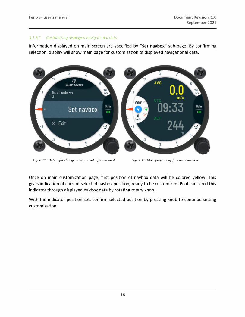
3.1.6.1 Customizing displayed navigational data
Information displayed on main screen are specified by “Set navbox” sub-page. By confirmingselection, display will show main page for customization of displayed navigational data.
Figure 11: Option for change navigational informational. Figure 12: Main page ready for customization.
Once on main customization page, first position of navbox data will be colored yellow. Thisgives indication of current selected navbox position, ready to be customized. Pilot can scroll thisindicator through displayed navbox data by rotating rotary knob.
With the indicator position set, confirm selected position by pressing knob to continue settingcustomization.
16

FenixS– user’s manual Document Revision: 1.0September 2021
On Select navbox subpage, pilot can scroll through the navigation list of data.
Figure 13: "Select navbox" page.
Selection can be made between the following data. Short press on rotary knob will confirmselection.
UTC Time Local time Flight time Leg time
Task t. left Task t. left Altitude Alt. QNH ft
Flight level Thermal gain Flarm alt. Distance Tp
Distance Apt Distance Tsk Distance Nrst Flarm dist.
Final glide Tp Final glide Apt Final glide Tsk Final glide Nrst
TAS IAS Ground speed Speed to fly
Vario Vario avg Vario netto Vario relative
Thermal avg Thermal max FLARM vario Track
Bearing Tp Bearing Tsk Bearing Apt Bearing Nrst
OAT ENL G-force F.ID
Efficiency(L/D) Tp req.L/D Apt req.L/D Tsk req.L/D
Nrst req.L/D
17
NOTE
Pilot can simply return or exit currently view page by long pressing rotary knob.

FenixS– user’s manual Document Revision: 1.0September 2021
3.1.7 Main page sub-menu
To access the sub-menu for adjusting MacCready, Ballast, Bugs, QNH, and Brightness both FenixS versions have a different approaches.
ADVANCE VERSION On advance version of the FenixS, the pilot must use short press to enter sub-menu on
main page. Value can be then change by rotating the rotary knob in CW or CCW direction. Every additional short press on the rotary knob will confirm last set value and jump to the next setting.
BASIC VERSION On basic version of the FenixS, rotating the rotary knob will automatically change the
main page view to the volume dialog.
Volume Vario setting. (Supported on Basic and Advance version)
Figure 14: Volume Vario set view.
MacCready setting.(Supported only in Advance version)
Figure 15: MacCready set view.
18

FenixS– user’s manual Document Revision: 1.0September 2021
Ballast setting.(Supported only in Advance version)
Figure 16: Ballast set view.
Bugs setting.(Supported only in Advance version)
Figure 17: Bugs set view.
QNH setting.(Supported on Basic and Advance version)
Figure 18: QNH set view.
19
FenixS– user’s manual Document Revision: 1.0September 2021
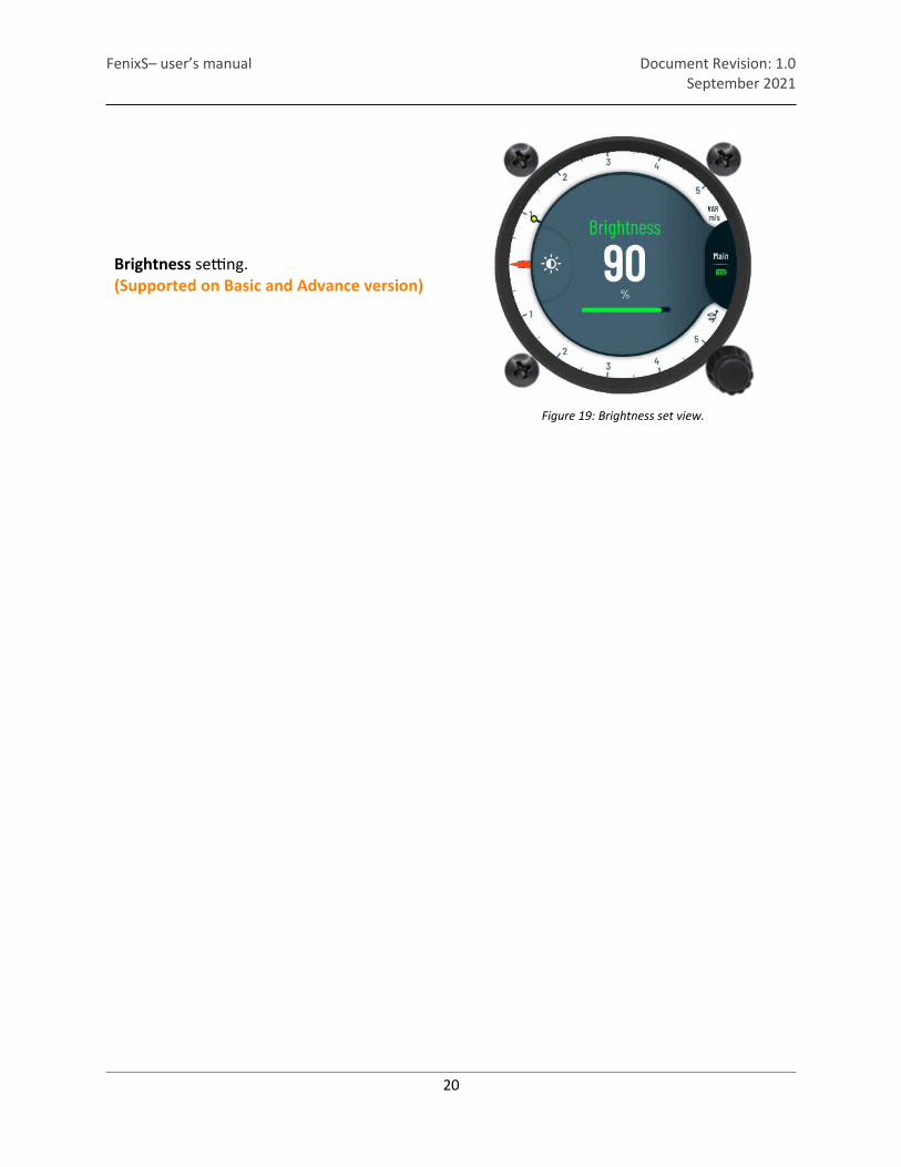
Brightness setting.(Supported on Basic and Advance version)
Figure 19: Brightness set view.
20

FenixS– user’s manual Document Revision: 1.0September 2021
3.2 Setup page
At setup page, configurations for system and user settings can be customized. The setting aresaved into internal device memory, so they needs to be entered only once.
In the Advance version, the pilot must rotate rotary knob to the Setup preview page. In the Basic version, to enter in the setting sub-page, only a short press on the rotary knob mustbe made.
Figure 20: Setup page view.
21
NOTE Setup preview page is only visible in Advance version of the FenixS.
FenixS– user’s manual Document Revision: 1.0September 2021
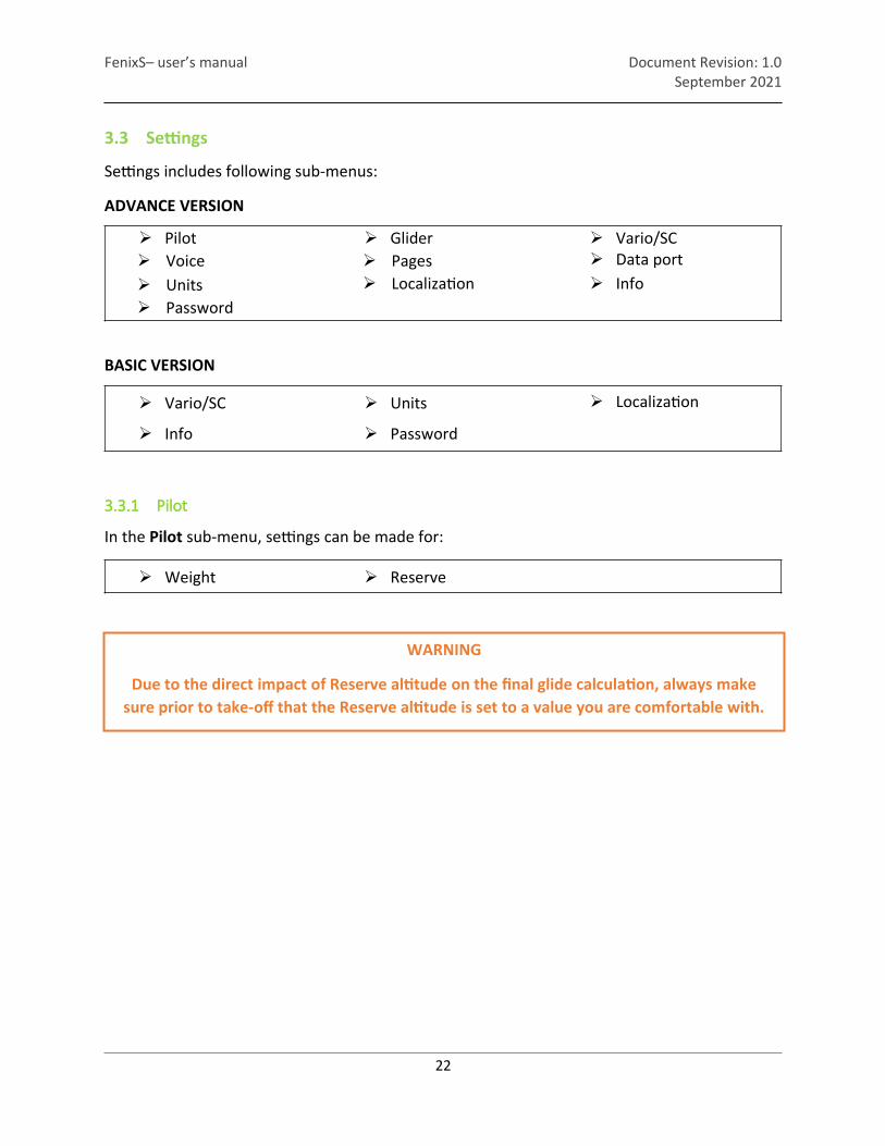
3.3 Settings
Settings includes following sub-menus:
ADVANCE VERSION
Pilot Glider Vario/SC Voice Pages Data port Units Localization Info Password
BASIC VERSION
Vario/SC Units Localization
Info Password
3.3.1 Pilot
In the Pilot sub-menu, settings can be made for:
Weight Reserve
22
WARNING
Due to the direct impact of Reserve altitude on the final glide calculation, always makesure prior to take-off that the Reserve altitude is set to a value you are comfortable with.

FenixS– user’s manual Document Revision: 1.0September 2021
3.3.2 Vario /SC
In the Vario/SC sub-menu, functionality of the Vario can be set and the following variablesadjusted:
Zero frequency – the frequency tone generated by device on displaying vario at 0 m/s. Positive frequency – the frequency tone generated by device on displaying vario at max
range. Negative frequency – the frequency tone generated by device on displaying vario at min
range. Test audio – selected option will output the tone from the negative frequency to the
positive frequency, allowing the pilot to hear current frequency range and adjust it ifneeded.
Range – lets the pilot adjust the current scale of selected vario unit (In the case of ktsnumbers 5, 10 or 20 can be set as scale). The same principle applies to other units.
Filter – increasing or decreasing this number will have an influence on variometer response.A smaller value will make the variometer more responsive to small changes, while a largervalue will do the opposite.
Integration time – interval for calculating average vario. Vario silence – the sound of vario will not be produced below this set value. This helps the
pilot to not be distracted from small changes in areas of the zero. This feature can be turnedoff or set between:
o -0.1 kts to -4.0 kts (For kts units)o -0.1 m/s to -2 m/s (For m/s units)
23

FenixS– user’s manual Document Revision: 1.0September 2021
3.3.3 Units
The displaying units for every numeric and graphical displayed indicator are adjusted in theUnits sub-menu. The following settings can be made on indicators:
24
AltitudeOptional units:
o fto m
Climb rateOptional units:
o m/s o m
SpeedOptional units:
o km/ho mpho kts
Wind speedOptional units:
o km/ho mpho ktso m/s
DistanceOptional units:
o kmo nmo mi
PressureOptional units:
o hPao inHg
TemperatureOptional units:
o °Co °F
MassOptional units:
o kgo Ib
Figure 21: Units page reference.
FenixS– user’s manual Document Revision: 1.0September 2021
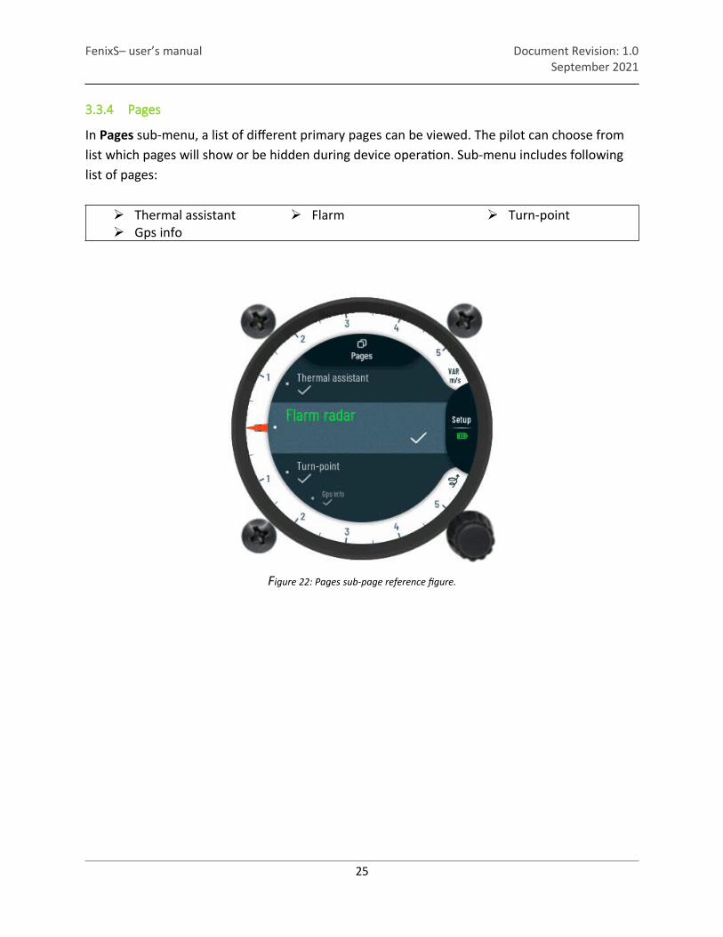
3.3.4 Pages
In Pages sub-menu, a list of different primary pages can be viewed. The pilot can choose from list which pages will show or be hidden during device operation. Sub-menu includes following list of pages:
Thermal assistant Flarm Turn-point Gps info
25
Figure 22: Pages sub-page reference figure.

FenixS– user’s manual Document Revision: 1.0September 2021
3.3.5 Voice
In the Voice setup sub-menu the pilot can adjust volume and mixer setting for voice warnings.Sub-menu also includes setting for additional voice alerts, which can be left disabled or enabledfor use during a flight. The “Voice” sub-menu includes following settings:
VolumeRange: 0% to 100%
Voice testTo test audio level.
Flarm trafficOptions:
o Enableo Disable
Flarm warningsOptions:
o Enableo Disable
Flarm obstacleOptions:
o Enableo Disable
Flarm h. distanceOptions:
o Enableo Disable
Flarm v. distanceOptions:
o Enableo Disable
26
Figure 23: Voice page reference.

FenixS– user’s manual Document Revision: 1.0September 2021
3.3.6 Glider
In Glider sub-menu all settings connected to properties of glider can be adjusted:
Select glider – entering setting will display a list of preinstalled types of the glider.Simply select the type of glider and confirm the selection.By confirming the type User polar, properties of glider type will be defined withvariables in sub-menu.
Polar A – variable to set polar A parameter of glider. Polar B – variable to set polar B parameter of glider. Polar C – variable to set polar C parameter of glider. Empty mass – variable to set empty mass of glider. Reference mass – variable to set reference mass of glider. Max mass – variable to set maximal mass of the glider. Wing area – variable to set wing area of glider.
27
Figure 24: Sub-menu Glider.
NOTE
Please see the documentation of your glider for all variables in “Glider” sub-menu.

FenixS– user’s manual Document Revision: 1.0September 2021
3.3.7 Data port
Working configuration of the external data port is set in sub-page Data port. The pilot can set the following parameter:
Data port 2 – parameter to set communication speed between the FenixS data port 2 and the externally connected device. The following data speeds can be chosen:
o BR4800o BR9600o BR19200o BR38400o BR57600o BR115200
28
Figure 25: Data port sub-page reference.

FenixS– user’s manual Document Revision: 1.0September 2021
3.3.8 Localization
Information and local settings can be set in the Localization sub-menu, containing preferred language and time zone.
Language – can be chosen between English and German. Time zone – for local time.
3.3.9 Info
Unique device identifiers can be seen in sub-menu Info. Displayed list shows followingidentifiers:
Serial nr. – serial number of FenixS unit. Firmware – current version of running firmware. Hardware – version of hardware used inside FenixS unit.
29
Figure 26: Localization subpage reference.
Figure 27: Info sub-menu reference.

FenixS– user’s manual Document Revision: 1.0September 2021
3.3.10 Password
Special function passwords can be used:
46486 – will set FenixS to factory default state (all settings are cleared and default are used)
99999 – will clear logbook.
30
Figure 28: Password page reference.
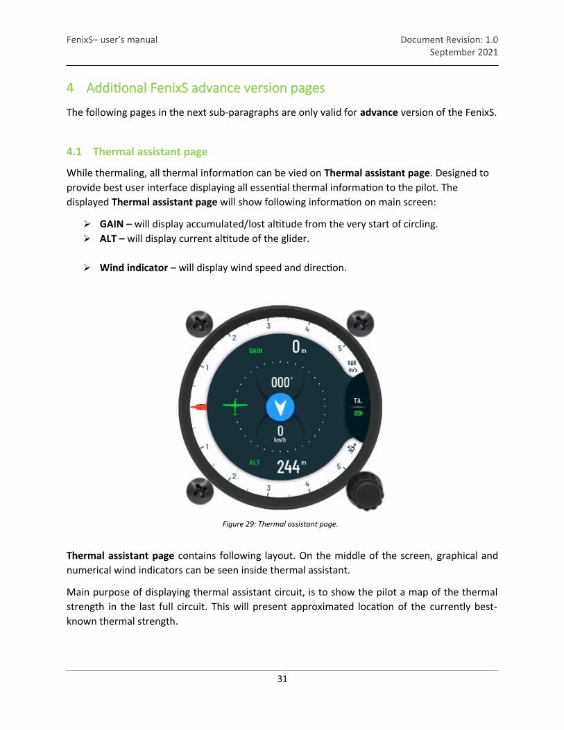
Figure 29: Thermal assistant page.
FenixS– user’s manual Document Revision: 1.0September 2021
4 Additional FenixS advance version pages
The following pages in the next sub-paragraphs are only valid for advance version of the FenixS.
4.1 Thermal assistant page
While thermaling, all thermal information can be vied on Thermal assistant page. Designed to provide best user interface displaying all essential thermal information to the pilot. The displayed Thermal assistant page will show following information on main screen:
GAIN – will display accumulated/lost altitude from the very start of circling. ALT – will display current altitude of the glider.
Wind indicator – will display wind speed and direction.
Thermal assistant page contains following layout. On the middle of the screen, graphical andnumerical wind indicators can be seen inside thermal assistant.
Main purpose of displaying thermal assistant circuit, is to show the pilot a map of the thermalstrength in the last full circuit. This will present approximated location of the currently best-known thermal strength.
31

FenixS– user’s manual Document Revision: 1.0September 2021
Thermal assistant page will start indicating strength of thermals with the size of the dots. Thelarger the displayed dots, the stronger is the thermal.
Colors of the dots, will display following type of the thermal:
Red circuit – will indicated positive thermal. Blue circuit – will indicated negative thermal.
Graphically displayed T.MAX value of the thermal can be seen on Thermal assistant page aslarge white dot.
Displayed green glider represents current positions of the pilot in the thermal. Left hand circlingwill display glider on the right side and right-hand circling will display glider on the left side.
Off-center, the integrated airspeed can be seen as well as altitude.
To enter the Thermal assistant submenu, the pilot must short press bottom rotary knob. Thermal assistant submenu holds the following functions, which can be enabled or disabled:
Auto switch – enabled will automatically switch to thermal assistant page when circling is detected.
MacCready colors – will represent climb stronger than 1.2*MC with red dots. Between 1.2*MC and 0.8*MC the color of the dots will be yellow and less than 0.8*MC will display blue dots.
Max beep / offset – will make the device beep when the glider is approaching the point of the T.MAX value. With offset set, Fenix will generate a beep by a set number of seconds before T.MAX position is reached.
32
Figure 30: Positive thermal with T.MAX circle. Figure 31: Negative thermal reference figure.
FenixS– user’s manual Document Revision: 1.0September 2021
4.2 Flarm radar page
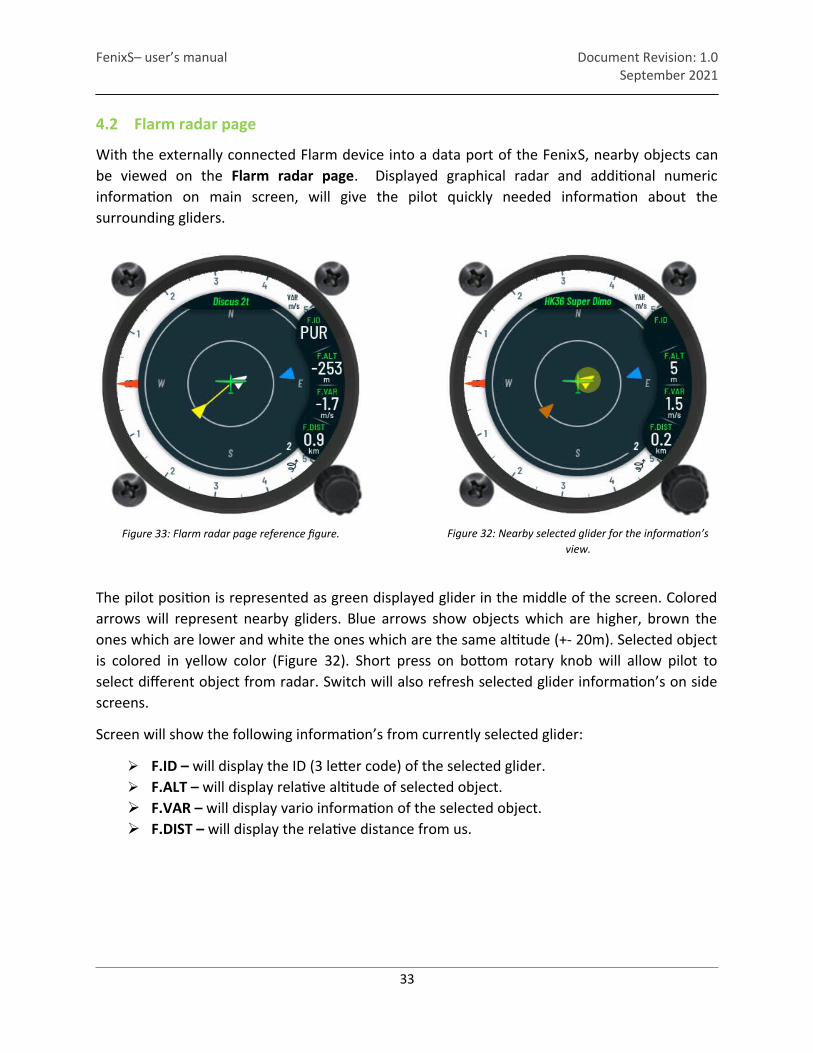
With the externally connected Flarm device into a data port of the FenixS, nearby objects canbe viewed on the Flarm radar page. Displayed graphical radar and additional numericinformation on main screen, will give the pilot quickly needed information about thesurrounding gliders.
The pilot position is represented as green displayed glider in the middle of the screen. Coloredarrows will represent nearby gliders. Blue arrows show objects which are higher, brown theones which are lower and white the ones which are the same altitude (+- 20m). Selected objectis colored in yellow color (Figure 32). Short press on bottom rotary knob will allow pilot toselect different object from radar. Switch will also refresh selected glider information’s on sidescreens.
Screen will show the following information’s from currently selected glider:
F.ID – will display the ID (3 letter code) of the selected glider. F.ALT – will display relative altitude of selected object. F.VAR – will display vario information of the selected object. F.DIST – will display the relative distance from us.
33
Figure 33: Flarm radar page reference figure. Figure 32: Nearby selected glider for the information’sview.
FenixS– user’s manual Document Revision: 1.0September 2021
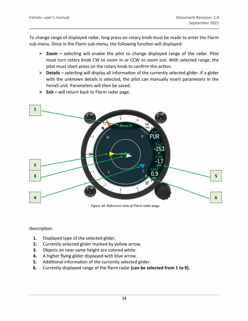
To change range of displayed radar, long press on rotary knob must be made to enter the Flarmsub-menu. Once in the Flarm sub-menu, the following function will displayed:
Zoom – selecting will enable the pilot to change displayed range of the radar. Pilotmust turn rotary knob CW to zoom in or CCW to zoom out. With selected range, thepilot must short press on the rotary knob to confirm this action.
Details – selecting will display all information of the currently selected glider. If a gliderwith the unknown details is selected, the pilot can manually insert parameters in theFenixS unit. Parameters will then be saved.
Exit – will return back to Flarm radar page.
1
Figure 34: Reference view of Flarm radar page.
2
3 5
4 6
Description:
1. Displayed type of the selected glider.2. Currently selected glider marked by yellow arrow.3. Objects on near same height are colored white.4. A higher flying glider displayed with blue arrow.5. Additional information of the currently selected glider.6. Currently displayed range of the flarm radar (can be selected from 1 to 9).
34

FenixS– user’s manual Document Revision: 1.0September 2021
4.3 Take-off info page
The Take-off page display the flight data from the last known take-off point. Yellow dot and linewill represent the direction to where the last know take-off point was detected.
To change range of displayed distance, short press on rotary knob must be made. Current zoomindicator will be colored red. To change to required zoom, pilot must turn rotary knob CW tozoom in or CCW to zoom out. With selected range, the pilot must short press on the rotaryknob to confirm this action.
1
Figure 35: Reference view of the Take-off page.
2
3 5
4 6
Description:
1. Displayed name of the info page.2. Last take-off position.3. Pilot position.4. FG information to the takeoff position.5. Navbox data.6. Current zoom of the displayed distance (can be selected from 1 to 30).
Additional navbox data can be seen on the right side of the display. Data will give the pilot aneasier representation of the current flight bearing, flight direction, and flight efficiency.
35

FenixS– user’s manual Document Revision: 1.0September 2021
ETP – displays required efficiently to reach the point. TRK – displays current direction of the flight. BRG – displays bearing direction to the take-off point. DIST – displays distance to the take-off point.
4.4 GPS info page
Once on GPS info page, following information can be seen:
Fix Quality / Satellite number – displaying receiving signal quality and number of satellites that are being received.
Latitude – displays GPS latitude. Longitude – displays GPS longitude. Time – UTC time. Date – current UTC date.
Figure 36: GPS Info page.
36

FenixS– user’s manual Document Revision: 1.0September 2021
4.5 Logbook page
In the ground stationary mode, the Logbook page will show its name on the screen. During this mode, the pilot can access list of flights with a short press on the rotary knob.
With the displayed list of last 50 flights, the pilot can scroll through the list by rotating thebottom rotary knob. On a list, date of takeoff, time of take-off / landing and flight time can beseen.
37
Figure 38: Logbook page view. Figure 37: List of saved flights.

FenixS– user’s manual Document Revision: 1.0September 2021
4.6 Flight statistic info page
Once the flight starts the Logbook page will be change to the Flight statistic page with the following available data to view:
Takeoff – displays time of take-off. Duration – displays duration of the flight.
38
Figure 39: Flight statistic info page.

FenixS– user’s manual Document Revision: 1.0September 2021
4.7 Warnings
For the warning references please see pictures below.
An Obstacle warning will be triggered if the pilot is to close to an obstacle.
Red rhombus will indicate, if for the nearby obstacle is higher or lower.
Figure 40: Obstacle warning view.
Traffic warning will indicate if aircraft is nearby. The red direction symbol will indicate the detected direction of the aircraft.
Red rhombus will indicate if the nearby aircraft is located below or above from our current height.
Figure 41: Low battery warning view.
39
FenixS– user’s manual Document Revision: 1.0September 2021
5 Rear of unit
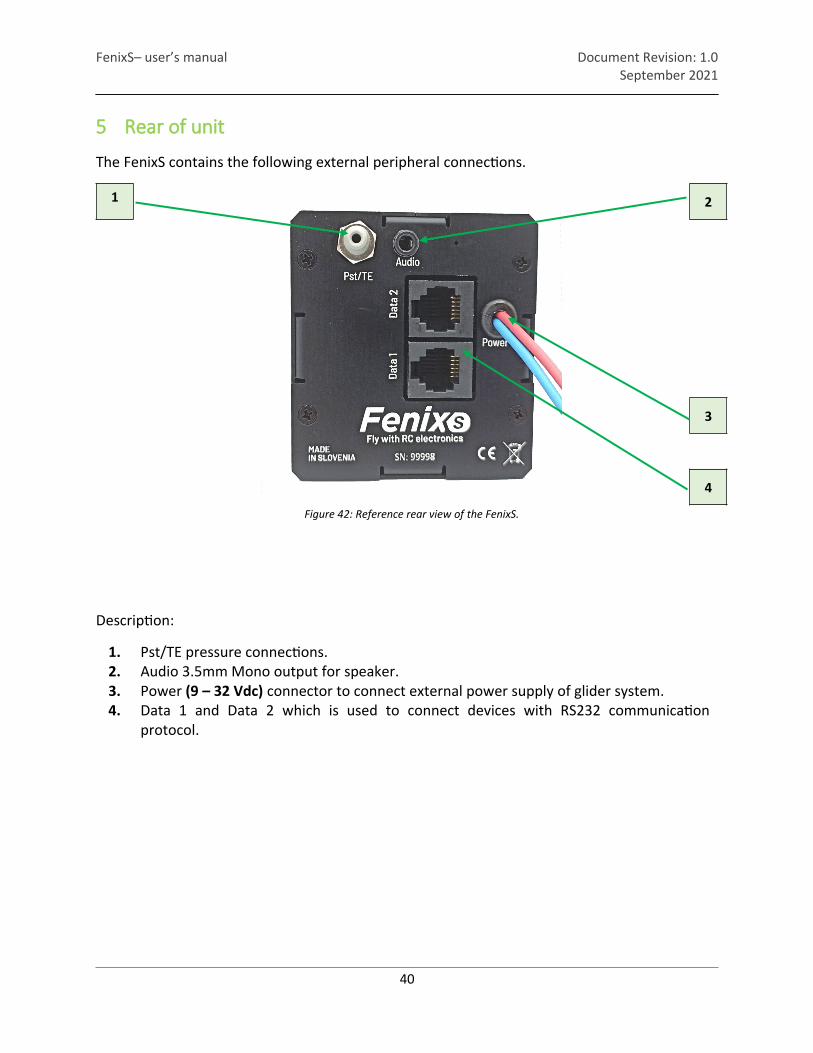
The FenixS contains the following external peripheral connections.
1
Figure 42: Reference rear view of the FenixS.
2
3
4
Description:
1. Pst/TE pressure connections.2. Audio 3.5mm Mono output for speaker.3. Power (9 – 32 Vdc) connector to connect external power supply of glider system.4. Data 1 and Data 2 which is used to connect devices with RS232 communication
protocol.
40

FenixS– user’s manual Document Revision: 1.0September 2021
5.1 Data port pinout
Pin number Pin description1 Power output (same voltage as on power cable 9-32V)2 Not used3 Not used4 RS232 data input (FenixS receives data)5 RS232 data output (FenixS transmits data)6 GND
41
Figure 43: Data connectors pinout.

FenixS– user’s manual Document Revision: 1.0September 2021
6 Bluetooth connectivity
FenixS Advance and FenixS Basic need an externally Bluetooth module connected to the Data 1 port to enable wireless connection.
6.1 Pairing
To pair your device with FenixS please initiate search of BT device on your PNA/PDA.
FenixSXXXXX, where XXXXX represents serial number of the unit, will be visible on detected list, when in range and turned on.
Pair code will be requested to start communication with PDA/PNA and FenixS. Just confirm the pair code being offered and devices will be successfully paired. After successful connection, Bluetooth icon is visible on main vario page.
6.2 Supported data transfers
Data transfer type Supported Note
PFLAx (Flarm data) yes Only via BT module
GPRMC yes Only via BT module
GPRMB yes Only via BT module
GPGGA yes Only via BT module
42

FenixS– user’s manual Document Revision: 1.0September 2021
7 Physical properties
This section is used to describe mechanical and electrical properties.
Dimensions 65mm x 62mm x 30mmWeight 120g
7.1 Electrical properties
POWER USAGESInput voltage 9V (Vdc) to 32V (Vdc)Input current 80mA @ 13V (Vdc)
AUDIO (POWER DELIVERY)Output power 1W (RMS) @ 8Ω
DATA PORTS (POWER DELIVERY)Output voltage Same as Input voltage of power connectorOutput current (MAX) -500 mA @ 9V (Vdc) to 32 (Vdc) per port
43

FenixS– user’s manual Document Revision: 1.0September 2021
8 Installation of the unit
8.1 Mechanical installation
FenixS unit fits in standard 57mm hole in instrumental panel so no extra cutout is required. To install the unit in instrumental panel, unscrew three mounting screws (black) with a screwdriverand knob of rotary switch.
To remove the knob do not use force. Remove the press-in cover first to get to the screw. After unscrewing the screw pull off the knob. Then unscrew mounting nut for rotary switches
Place the unit in the instrumental panel and first screw in the two black screws and then mounting nuts for rotary switches. After that put back the knob on the rotary switch. Don’t forget to screw the knob in place and put the press-in cover back on.
8.2 Pneumatic connections
FenixS has only one pressure intake port on the back of the unit. It’s function is described by the label next to a port.
Pst/TE – Static pressure
Connect it to TE probe for compensating vario indication or to static port for non compensated vario indication.
9 Flight Recorder
The flight recorder doesn’t need any special care as it works nearly automatically without pilot assistance.
44

FenixS– user’s manual Document Revision: 1.0September 2021
9.1 Start and stop of flight recording
The unit will start recording immediately after start conditions are met. Start conditions are based on ground speed and altitude change, so even if the GPS status is bad during takeoff, the unit will start recording. It is recommended to switch the unit on a few minutes before takeoff. After landing the unit will close the flight after approximately 20 seconds at standstill, so it is recommended to keep the unit under power until flight is finished. To determine if the flight recorder has closed the flight, check Logbook->Statistic page. If the Logbook appears, the recording has finished, if the statistic page appears, the flight mode is still active.
45
FenixS– user’s manual Document Revision: 1.0September 2021
10 Flying with FenixS
To get the best out of the unit, it is import ant that some preparation is done prior to the flight. Pre-flight preparation will ensure that the flight will be both successful and enjoyable.
10.1 Before take-off
- Switch the unit ON at least 3 minutes before take-off (this will ensure sufficient GPS reception if external GPS module is connected).
10.1.1 Set Elevation
The pilot should set elevation of airport if he wish to fly QNH mode of set elevation to 0 to fly QFE.
10.1.2 Set QNH
The pilot should input actual QNH value of the entered elevation. This will allow pilot to adjust daily pressure during the day to have correct altitude information during the flight.
10.2 During flight
The unit hardware and firmware concept are so far optimized that the pilot doesn’t spend too much time to operate the unit during flight. A very significant indication that shows that the unit has changed to flying mode is Logbook replacement with Statistics page.
10.2.1 Set QNH Change of QNH in main page quick setup menu will adjust altitude reading to actual QNH set-ting.
10.2.2 Wind calculation
Unit is able to measure wind under circling method. Wind calculation results are shown on windindicator which is part of many pages.
Circling: Calculation is based on ground speed change due to wind influence in circling. The method is active exclusively during climbing process. The process start automatically after circ-ling is detected. The method is based on fact that the ground speed is affected by the wind. GS is maximal by tailwind and minimal by head wind. This phenomenon is used by GS difference calculation method.
46
FenixS– user’s manual Document Revision: 1.0September 2021
10.2.3 Influence of wind in final glide
The actual wind data (speed and direction) influences the final glide calculation.
10.3 After landing
It is recommended to keep the instrument on for a few minutes after landing so unit will detect landing state. At this point unit can be switched OFF.
47