
IV. The (Extended) Entity-Relationship Model The Extended Entity ...

TheeffectoncrackingofhighcoversinRCbeamsFilipa Marques Guedes
Instituto Superior Técnico, University of Lisbon, Portugal
Abstract:Thisstudyfocusesontheeffectof largecoversinRCbeamsoncrackformation.The
motivation for thiswork came from the need to clarify the implications of using these high
covers.WiththehelpofRegulationssuchasREBAP,EC2-2010,NBR6118,ACI318-95,CEB-FIP
ModelCode1990and2010,andwiththeresultsoftestspreformedbyAlejandroCaldenteyit
waspossibletoconcludethatthesizeof crackwidth increaseswiththesizeofthecoverof
thereinforcement.
Key-Words:crack formation,RCbeams, cover,REBAP,EC2-2010,NBR6118,ACI318-95,CEB-FIP
MC90,Model2010andcrackwidht.
1 IntroductionThe main goal of this work is to study theeffect of cover on the cracking behavior ofreinforced concrete elements. Importanttheoretical aspects are discussed, includingwhere the crackwidth is estimatedby currentcodes formulations aswell as a detailed studyof each Code,mentioned above. And to finishthisstudy,acomparisonbetweenresultsgivenby current codes and experimental tests ismade, concluding that crack widths estimatedbymathematicalformulations,givenbyREBAP,EC2, NBR, ACI, CEB-FIP 90 and Model Code2010, are smaller that the ones estimated byexperimentaltests.
These experimental programme involving 12beamsspecimenswascarriedoutatStructuresLaboratory of the Civil Engineering School ofthePolytechnicUniversityofMadridfromMaytoOctober2009.
The specimens were coded XX-YY-ZZ, with XXreferring to bar diameter (12 or 25), YYreferringtocover(20or70cm)anZZreferringtostirrupspacing(00fornostirrup,10and30,for10cmand30cmspacing,respectively.
2 CrackwidthbyRegulations2.1 RebapREBAPrequiresthatcrackingshouldbelimited
to a level that does not impair the proper
functioning of the structure or cause its
appearance to be unacceptable. The code
stipulatesthatthedesignandmeancrackwidth
beevaluatedfromthefollowingexpression:
𝑤! =1,7.𝑤!(2.1)
𝑤!=𝑆!".𝜀!"(2.2)
with,
𝑆!":averagestabilizedcrackspacing;
𝜀!":averagereinforcementstrainwthin
segmentlenght𝑙!,!á!;
Average Stabilized crack spacing is expressed
as:
𝑆!"=2. 𝑐 +!!"
+ 𝜂!. 𝜂!.!!! (3)
with,

c:coverofreinforcement;
s:spacingofthereinforcement;
𝜂!=0,4fordeformedbars;
=0,8forplainbars;
𝜂!=0,25.!!!!!!!!
𝜙:bardiameter;
𝜌!:effectivereinforcementratio !!!!,!""
;
TheeffectiveconcreteareaiseshowninFigure
2-1.
The average reinforcement strain is obtained
fromthefollowingexpression:
𝜀!"=!!!!. ( 1 − 𝛽!.𝛽!. (
!!"!!)!)(4)
with,
𝜎!:reinforcementstressatthecrack;
𝐸!:Modulusofelastecityofthereinforement;
𝛽!:coefficientaccountingforbarbond
characteristics(=1,0fordeformnedbarsand
0,5forplainbars);
𝛽!:coefficientaccountingforloadduration
(=1,0forsingleshort-termloadingand0,5for
sustainedorcyclicloading);
𝜎!":stressinthetensionreinforcement
computedonthebasisofacracksectionunder
loadingconditionsthatcausethefirstcrack;
𝜀!"≥0,4.( 𝜎!/𝐸!). (5)
2.2 EC2
TheEurocodeEC2requiresthatcrackingshould
belimitedtoavalueofmaximumdesigncrack
of 0,3 mm, for sustained load under normal
environmental conditions. This ceiling is
expected to be satisfactory with respect to
appearance and durability. Strcker
requirements are stipulated for more severe
environmentalconditions.
Thecodestipulatesthatthedesigncrackwidth
beevaluatedfromthefollowingexpression:
𝑤!=𝑆!,!á!.( 𝜀!"-𝜀!")(2.2.1)
( 𝜀!"- 𝜀!") is obtained from the following
expression:
𝜀!"-𝜀!"=!!!!!.
!"#,!""!!,!""
.(!!!!.!!,!"")
!!≥ 0,6. !!
!!
(2.2.2)
with,
𝛼!=𝐸!/𝐸!";
ℎ!,!""=min(2,5.(h-d),(h-x)/3,h/2);
𝑘!:coefficientaccountingforloadduration
(=0,6forshort-termloadingand0,4for
sustainedorcyclicloading);
TheeffectiveconcreteareaiseshowninFigure
2-2
Figure1-1:EffectiveconcreteáreaforREBAP
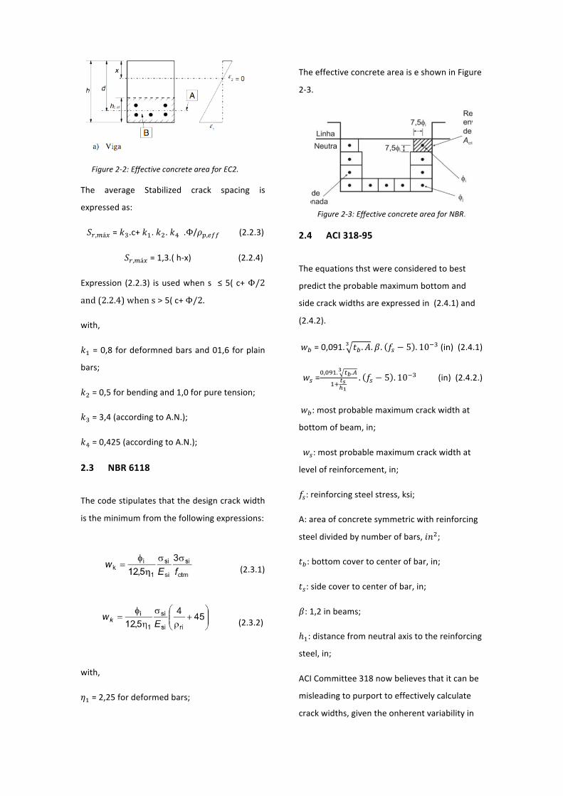
The average Stabilized crack spacing is
expressedas:
𝑆!,!á!=𝑘!.c+𝑘!. 𝑘!. 𝑘!.Φ/𝜌!,!""(2.2.3)
𝑆!,!á!=1,3.(h-x) (2.2.4)
Expression (2.2.3) isusedwhens ≤5(c+Φ/2
and(2.2.4)whens>5(c+Φ/2.
with,
𝑘!=0,8fordeformnedbarsand01,6forplain
bars;
𝑘!=0,5forbendingand1,0forpuretension;
𝑘!=3,4(accordingtoA.N.);
𝑘!=0,425(accordingtoA.N.);
2.3 NBR6118
Thecodestipulatesthatthedesigncrackwidth
istheminimumfromthefollowingexpressions:
(2.3.1)
(2.3.2)
with,
𝜂!=2,25fordeformedbars;
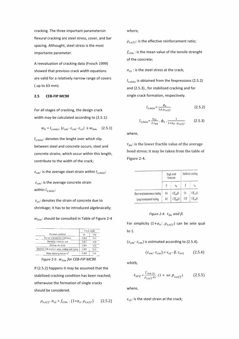
TheeffectiveconcreteareaiseshowninFigure
2-3.
2.4 ACI318-95
Theequationsthstwereconsideredtobest
predicttheprobablemaximumbottomand
sidecrackwidthsareexpressedin(2.4.1)and
(2.4.2).
𝑤!=0,091. 𝑡! .𝐴! .𝛽. 𝑓! − 5 . 10!!(in)(2.4.1)
𝑤!=!,!"#. !!.!
!
!! !!!!. 𝑓! − 5 . 10!!(in)(2.4.2.)
𝑤!:mostprobablemaximumcrackwidthat
bottomofbeam,in;
𝑤!:mostprobablemaximumcrackwidthat
levelofreinforcement,in;
𝑓!:reinforcingsteelstress,ksi;
A:areaofconcretesymmetricwithreinforcing
steeldividedbynumberofbars,𝑖𝑛!;
𝑡!:bottomcovertocenterofbar,in;
𝑡!:sidecovertocenterofbar,in;
𝛽:1,2inbeams;
ℎ!:distancefromneutralaxistothereinforcing
steel,in;
ACICommittee318nowbelievesthatitcanbe
misleadingtopurporttoeffectivelycalculate
crackwidths,giventheonherentvariabilityin
Figure2-2:EffectiveconcreteareaforEC2.
Figure2-3:EffectiveconcreteareaforNBR.
cracking.Thethreeimportantparametersin
flexuralcrackingaresteelstress,cover,andbar
spacing.Althought,steelstressisthemost
importanteparameter.
Areevaluationofcrackingdata(Frosch1999)
showedthatpreviouscrackwidthequations
arevalidforarelativelynarrowrangeofcovers
(upto63mm).
2.5 CEB-FIPMC90
Forallstagesofcracking,thedesigncrack
widthmaybecalculatedaccordingto(2.5.1):
𝑤!=𝑙!,!á!.(𝜀!"- 𝜀!"- 𝜀!")≤𝑤!"#(2.5.1)
𝑙!,!á!:denotesthelenghtoverwhichslip
betweensteelandconcreteoccurs;steeland
concretestrains,whichoccurwithinthislength,
contributetothewidthofthecrack;
𝜀!":istheaveragesteelstrainwithin𝑙!,!á!;
𝜀!":istheaverageconcretestrain
within 𝑙!,!á!;
𝜀!":denotesthestrainofconcretedueto
shrinkage;ithastobeintroducedalgebraically;
𝑤!"#:shouldbeconsultedinTableofFigure2-4
If(2.5.2)happensitmaybeassumedthatthe
stabilizedcrackingconditionhasbeenreached,
otherwuisetheformationofsinglecracks
shouldbeconsidered.
𝜌!,!"" .𝜎!!>𝑓!"# .(1+𝛼! . 𝜌!,!"")(2.5.2)
where,
𝜌!,!"":istheeffectivereinforcementratio;
𝑓!"# :isthemeanvalueofthetensilestrenght
oftheconcrete;
𝜎!!:isthesteelstressatthecrack;
𝑙!,!á!isobtainedfromthefexpressions(2.5.2)
and(2.5.3).,forstabilizedcrackingandfor
singlecrackformation,respectively.
𝑙!,!á!=!!
!,!.!!,!""(2.5.2)
𝑙!,!á!=!!! !.!!"
.𝜙!.!
!!!!: .!!,!""(2.5.3)
where,
𝜏!":isthelowerfractilevalueoftheaverage
bondstress;itmaybetakenfromthetableof
Figure2-4.
For simplicity (1+𝛼!: . 𝜌!,!"") can be sete qual
to1.
(𝜀!"- 𝜀!")isestimatedaccordingto(2.5.4).
(𝜀!"-𝜀!").=𝜀!!-β.𝜀!"!(2.5.4)
whith,
𝜀!"!=𝑓𝑐𝑡𝑚 (𝑡)𝜌𝑠,𝑒𝑓𝑓.!"
. (1 + 𝛼𝑒.𝜌𝑠,𝑒𝑓𝑓)(2.5.5)
where,
𝜀!!:isthesteelstrainatthecrack;
Figure2-5:𝑤!"#forCEB-FIPMC90
Figure2-4:𝜏!"andβ.
𝜀!"!:isthesteelstrainatthecrack,under
forcescausing𝑓!"# within𝐴!,!"";
Forstabilizedcrackingtheaveragewidhtmay
beestimaedonthebasisofanaveragecrack
spacingof:
𝑆!"=!!. 𝑙!,!á! (2.5.6)
TheeffectiveconcreteareaiseshowninFigure
2-6.
2.6 ModelCode2010Itshouldbeensuredthatcrackswillnotimpair
the serviceability and durability of the
structure. cracks donot, per se, indicate a lack
of serviceability or durability, in reinforced
concretestructures
For all stages of cracking, the designg crack
width𝑤!maybecalculatedby(2.6.1):
𝑤!=2.𝑙!,!á!.(𝜀!"- 𝜀!"- 𝜀!")(2.6.1)
where,
𝑙!,!á!: denotes the length over which slip,
betweenconcreteandsteeloccurs.
𝜀!":istheaveragesteelstrainoverthelenght
𝑙!,!á!;
Thelength𝑙!,!á!,canbeexpressedby(2.6.2):
𝑙!,!á!=k.c+!!.!"#$!!"#
. !"!!,!""
(2.6.2)
k : is an empirical parameter to take the
influence of the concrete cover into
consideration.Asasimplificationk=1,0canbe
assumed;
c:istheconcretecover;
𝜏!"# : is mean bond strength between steel
andconcrete;
Therelativemeanstrainfollowsfrom:
𝜀!"- 𝜀!"- 𝜀!"=!!!!.!!"
!"+ 𝜂! . 𝜀!! (2.6.3)
where,
𝜎!:isthesteelstraininacrack;
𝜎!":isthemaximumsteelstressinacrack
formationstage,which,forpurtensionis:
𝜎!"=!"#$!!,!""
(1 + 𝛼! . 𝜌!,!"")(2.6.4)
𝛽:isanempiricalcoefficienttoassessthemean
strainover𝑙!,!á! ,dependingonthetypeof
loading;
𝜂!:isacoefficientforconsideringtheshrinkage
contribution;
𝜀!!:istheshrinkagestrain;
Thevaluefor𝜏!"#,𝛽and𝜂!canbetakenfrom
Figure2-7:
Figure2-6:effectiveconcreteareaforCEB-FIPMC90.
Figure2-7: 𝜏!"#,𝛽and𝜂! values.

Inordertoestimatethevalueofthecrack
widthattheextremetensilefibre,thecrack
widthmaybemultipliedwithafactor(h-x)/(d-
x).
Equation(2.6.2)Isvalidforstructureswhere
theconcretecoverisnotlargerthan75mm.
TheeffectiveconcreteareaiseshowninFigure
2-6,sameasCEB-FIPMC90.
3 ExampleofcrackwidhtcalculationaccordingtoRegulations
3.1 ExampleDefinition
FortheRCbeamshowedinFigure3-1,astudy
ofcrackwidthwasmade,forthis,itwasuseda
rangeofcovers,startingat3cm,followedby5,
7and10cm.
Thedataforthisexerciseisshowedbellow:
• M=1090kN.m;
• 𝐴!=24,544𝑐𝑚!;
• 𝐴500NRandC25/30;
• ℎ=2,0mandb=1,0m;
• Shorttermloading;
3.2 ComparisonofRegulationsResults
Thiscomparisonismadeforcracksat
reinforcementlevel,calculatedbyallsix
Regulationsmentionedabove.Table2-1and
Figure3-2showsthefinalresults.
To this end, and with the help of Regulations
such as REBAP, EC2-2010,NBR 6118, ACI 318-
95,CEB-FIPModelCode1990and2010,which
wereanalyzedindividuallyforthecalculationof
crackwidht,forthisrangeofvaluesforcovers,
thefirstimmediateconclusionwasthatthesize
of crack width increases with the size of the
coverofthereinforcement.
These results confirm that cover is an
important factor in the development of the
crackingpattern.
Figure3-1:RCbeamstudiedforcrackwidth.
Table2-1:Crackwidthsaccordingtoregulations
Figure3-2:crackwidthaccordingtoregulations.
4 Comparisonwithexperimentaltests4.1 Descriptionoftests
An experimental programme involving 12
beams specimens was carried out at the
Structures Laboratory of the Civil Engineering
SchoolofthePolytechnicUniversityofMadrid.
Allbeamshada rectangular cross-section0,35
mwide and 0,45m deep, all specimens were
concreted at the same time using the same
concreteofstrengthclassC25/33.
Theparametersstudiedwerecover(20and70
mm) and stirrup spacing 𝑠!. For this, three
configurations were considered, no stirrups,
and stirrups spaced at 10 and 30 cm. Stirrup
diameter was 12 mm, the specimens were
coded XX-YY-ZZ, with XX referring to bar
diameter(25mm),YYreferringtocover(20or
70mm)andZZ referring tostirrupspacing (00
fornostirrups,10for10cmspacingand30for
30 cm spacing). The cross-sections of the
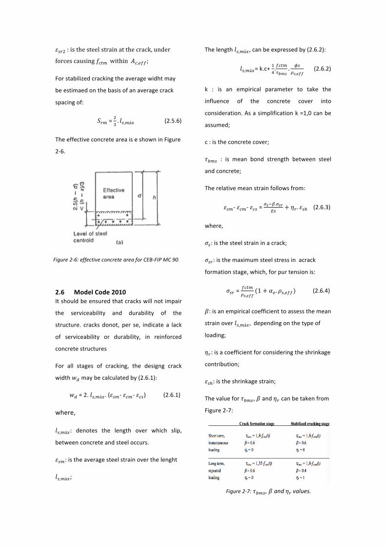
specimensareshowninFigure4-1.
4.2 TestResults
Asummaryoftestresultsintermsofmean𝑠!,!
andmaximum 𝑠!,!"# crack spacing is given in
Table4-1.
Figure 4-2 shows very clearly how cover
increases crack width. This increase is clearly
related to an increase in crack spacing. These
resultsconfirmthatoverisanimportantfactor
inthedevelopmentofthecrackingpattern.
Assaidin 7 “Fromatheoreticalpointofview,
the effect of cover on crack spacing can be
understood by the need to transmit tension
stresses generated at the bar-concrete
Figure4-2:Cross-sectionofthespecimens.
Table4-1:testresultsintermsof𝑠!,!and𝑠!,!"#
Figure4-1:Sidemaximumcrackwidthvseffectofcover(ϕ=25mm)
interface to the effective concrete area
surroundingthebarinordertogenerateactual
cracking.
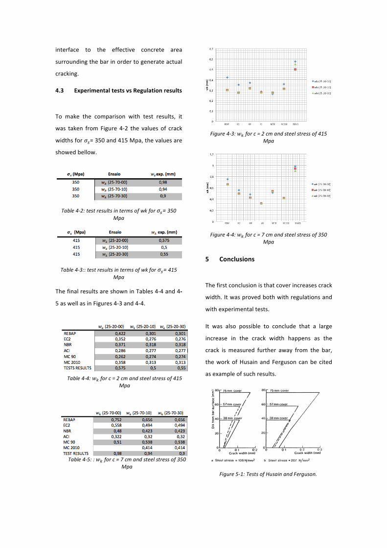
4.3 ExperimentaltestsvsRegulationresults
To make the comparison with test results, it
was taken from Figure 4-2 the values of crack
widthsfor𝜎!=350and415Mpa,thevaluesare
showedbellow.
ThefinalresultsareshowninTables4-4and4-
5aswellasinFigures4-3and4-4.
5 Conclusions
Thefirstconclusionisthatcoverincreasescrack
width.Itwasprovedbothwithregulationsand
withexperimentaltests.
It was also possible to conclude that a large
increase in the crack width happens as the
crack is measured further away from the bar,
theworkofHusain and Ferguson canbe cited
asexampleofsuchresults.
Table4-2:testresultsintermsofwkfor𝜎!=350Mpa
Table4-3::testresultsintermsofwkfor𝜎!=415Mpa
Table4-4:𝑤! forc=2cmandsteelstressof415Mpa
Table4-5::𝑤! forc=7cmandsteelstressof350Mpa
Figure4-3: 𝑤! forc=2cmandsteelstressof415Mpa
Figure4-4: 𝑤! forc=7cmandsteelstressof350Mpa
Figure5-1:TestsofHusainandFerguson.

The large difference between crack spacing at
thereinforcementsurfaceandcrackspacingat
the concrete surface observed in tests can be
attributed to internal cracking, At the bar
surface the differential strain between steel
and concrete is distributed among the passing
crackandtheinternalnon-passingcrack.
Other important fact verified was that crack
width calculations using current codes is
actualllysmallerthattheonesmeasuredinthe
experimentaltests.
Itcanbeseen,byFigure5-2,thatcrackstendto
developatthestirruppositions.
Tests have also confirmed that stirrup spacing
has an influence on crack spacing, but this
influence is mainly relevant for mean crack
spacing, we know that the variable important
for the verification of serviceability limit state
ofcracking ismaximumcrackspacing,andthis
itsinfluenceonmaximumcrackspacingismuch
smaller.
References
1 REBAP1SÉRIE–N.ª174–30/07/1983
2 NPEN1992-1-1Eurocódigo2-Projectode
estruturasdebetãoParte1-1:Regrasgeraise
Regrasparaedifícios
3 ABNTNBR6118_2003NORMABRASILEIRA,
PROJETODEESTRUTURASDECONCRETO-
PROCEDIMENTO
4 ACI224R–01CONTROLOFCRACKINGIN
CONCRETESTRUCTURES
5 CEB-FIPMODELCODE–1990COMITEEURO
–INTERNATIONALDUBETON
6 MODELCODE2010FINALDRAFTSPECIAL
ACTIVITYGROUP5
7 A.Caldentey,H.Peiretti,J.Iribarren,A.
Soto,“CrackingofRCmembersrevisited:
Influenceofcover,Φ/𝜌!,!",andstirrupspacing
–anexperimentalandtheoreticalstudy”
8 Appleton,J.2013:“Estruturasdebetão-
Volumes1e2”,EdiçõesOrion,Amadora
9 CritériosdeProjectocivildeusinas
hidrelétricas.Eletrobrás.CBDB.Outobro2003
Figure5-2:Crackpatterngovernedbystirrup
spacinginatestcarriedoutbyGómezNavarro.


![SCENARIO ANALYSIS - fenix.tecnico.ulisboa.pt · António Alvarenga 1st SEMESTER, 2015 ... [ “Beatriz”]; » “Inês - Rui”; » “Rita”. ... SCENARIO ANALYSIS Experimentation](https://static.fdocuments.us/doc/165x107/5b5394f57f8b9a27658bdf18/scenario-analysis-fenix-antonio-alvarenga-1st-semester-2015-beatriz.jpg)


