FEM Analysis of Stress Distribution in Force-Balanced Coils
23
FEM Analysis of Stress Distribution in Force-Balanced Coils H. Tsutsui , S. Kajita, Y. Ohata, S. Nomura, S. Tsuji-Iio, R. Shimada Research Laboratory for Nuclear Reactors, Tokyo Institute of Technology 18th International Conference on Magnet Technology October 20-24, 2003, Morioka, Japan
Transcript of FEM Analysis of Stress Distribution in Force-Balanced Coils

FEM Analysis of Stress Distribution in Force-Balanced Coils
H. Tsutsui, S. Kajita, Y. Ohata, S. Nomura,
S. Tsuji-Iio, R. Shimada
Research Laboratory for Nuclear Reactors, Tokyo Institute of Technology
18th International Conference on Magnet TechnologyOctober 20-24, 2003, Morioka, Japan

Introduction
• The virial theorem is the relation between the kinetic and the potential energies. The theorem, which is derived only form the equilibrium, shows that the tension is required to hold the magnetic energy.
• Using the virial theorem, we extended and generalized Force-Balanced Coil which is a helical type hybrid coil of the toroidal field (TF) coil and the solenoidal coil, and showed the condition to minimize the stress working in the coil (virial-limit condition).
• In this work, we constructed a small device to prove our concept, and obtained stress distribution experimentally. The results are compared with those of numerical calculations with a shell model.

Principle of Force-Balanced Coil
FcI
Fca R
R FhFh
Fc
I
Fc
aR
aR Fh
I
Fh
Hoop Force by Toroidal Current
Centering Force by Poloidal Current
Force-Balanced Coil
Centering force is much reduced,
butstress distribution
is not investigated.

Virial Theorem
tensorstress
field magnetic :
densitycurrent :
0
0
0
:S
S
B
j
BjB
Bj
=⋅∇=×∇
=⋅∇+×µ
( )
tensorstress Maxwell
2
02
0
:T
IT
ST
−≡
=+⋅∇
BBBµ1
( )
stress principal :
0d2
d
0d Tr
M0
23
1
i
ii UVBV
V
σµ
σ >≡=
=+
∫∫∑
∫
=
ST Ω
Ω
∫≡
≡
VV
UV
d
~M
σσ
σσ
1~3
1
=∑=i
iσ
• Positive stress (tension) is required to hold the field.• Uniform tension is favorable.• Theoretical limit is determined.
Equilibrium Eq.
31~~~
321 === σσσ

Application to Thin Toroidal Shell
φ θ Sumation
Stress
Integral
Energy
ρπµ θ
∆−
RIa
2
220
16 ρπµ θ
∆RIa
2
220
8
RIa
4
220 θµ
RIa
4
220 θµ
RIa
2
220 θµ
RIa
4
220 θµ−
TF Coil (Major radius: R, minor radius: a, thickness: ∆ρ)
• We consider the toroidal coil with so large aspect ratio that toroidal effect is negligible.
• The current distribution is adopted which makes toroidal surface correspond to both current and magnetic surfaces.
• When torus is axisymmetric, the direction of principal stresses are φand θ.
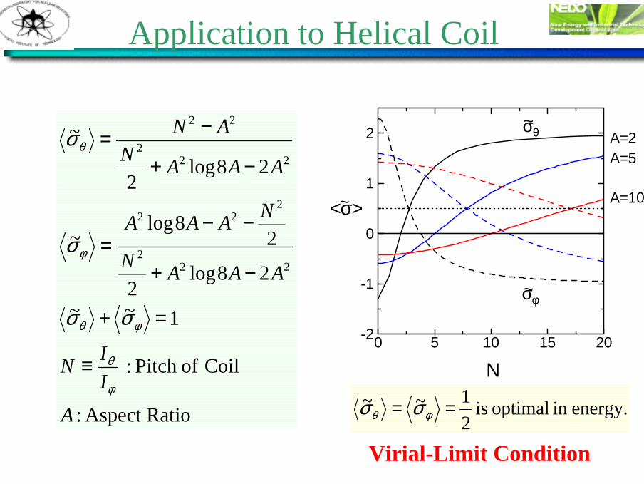
Application to Helical Coil
ioAspect Rat :
Coil of Pitch:
1~~
28log2
28log
~
28log2
~
222
222
222
22
AIIN
AAAN
NAAA
AAANAN
φ
θ
φθ
φ
θ
σσ
σ
σ
≡
=+
−+
−−=
−+
−=
N
<σ>
σφ
σθ A=2A=5
A=10
~
~
~
0 5 10 15 20-2
-1
0
1
2
energy.in optimal is 21~~ == φθ σσ
Virial-Limit Condition

Shape of Coils
<σφ>=0N=9FBC
<σθ>=0N=4
<σφ>= <σθ>N=6VLC
A
N
σθ=0
σφ=0 σθ=σφ
0 5 10 15
10
20
30
Aspect Ratio A =4
Relations of pitch number and aspect ratio of Virial-Limit Coil (VLC) etc.

Comparison of Maximum Averaged Stress
• Neglecting the distribution of stress by thetoroidal effect, the maximum stress is reduced to 25% compared with that of traditional TF coil.
A
<σ>
TFC
PFC
FBC
~max
VLC10 200
1
2
3
0.5
N=∞
N=0

Toroidal Effect
• Distribution of stress in the toroidal shell with circular cross section is derived analytically by use of magnetic pressure.
z
rR
aρ
θφ
o
0
22
2µθφ BB
p−
≡
∫≡r
Rrrpraru 'd)'(')(
2)(
)(
Rru
RrarpT
rRruT
−−
−=
−=
φ
θ
Equilibrium of Magnetic Pressure and Stress

Distribution of Stress(large aspect ratio)
• When A=100, distribution of stress is flat.• There is no advantage of helical winding.
A=100
0
22
M
T
2ˆ
µθφ BB
UVp
−≡
θ
pσ
^^
TFC
<σφ>=0
<σφ>=<σθ>σφ
σθ
p
0 1 2 3
0.8
0.9
1
-1
0
1
2
θ
pσ
^^
TFC<σφ>=0<σφ>=<σθ>
σφ
σθ
p
0 1 2 3
0.6
0.8
1
1.2
-1
0
1
2
A=10

Distribution of Stress(low aspect ratio)
• When A<10, distribution of stress is important.
• Assumption of large aspect ratio is not held.
• Optimal distribution is achieved to minimize the stressat θ=π.
A=2
θ
pσ
^^
TFC<σφ>=0
<σφ>=<σθ>
σφ
σθ
p
σφ(π)=σθ(π)
0 1 2 3-2
0
2
4
-2
0
2
4
N=3

Frame of Device to demonstrate VLC
• It is made of Al with 2mm-14mm thickness so that the strain is 10-5
-10-4 when the maximum field is 1T.
288 mm400 mm512 mm
for Hall sensors
φ12
A
A
BB
C
C
25 mmA-A
B-B
C-C
84 mm100 mm112 mm
14 mm
Frame of aluminum alloyInner Coil
Outer Coil

Device to demonstrate Virial-Limit Condition
+I
-I
Frame
Outer CoilInner Coil
IOUTIIN
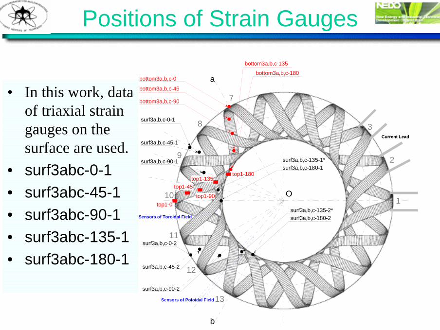
Positions of Strain Gauges
• In this work, data of triaxial strain gauges on the surface are used.
• surf3abc-0-1• surf3abc-45-1• surf3abc-90-1• surf3abc-135-1• surf3abc-180-1
7
10
13
O
a
b
8
9
11
12
bottom3a,b,c-0
bottom3a,b,c-45
bottom3a,b,c-90
bottom3a,b,c-135bottom3a,b,c-180
surf3a,b,c-0-1
surf3a,b,c-45-1
surf3a,b,c-90-1 surf3a,b,c-135-1*surf3a,b,c-180-1
surf3a,b,c-0-2
surf3a,b,c-45-2
surf3a,b,c-90-2
surf3a,b,c-135-2*surf3a,b,c-180-2
top1-0
top1-45top1-90
top1-135top1-180
Sensors of Toroidal Field
Sensors of Poloidal Field
1
2
3Current Lead

Shell model with periodic symmetry
Equilibirum Equation
α: amplitude of modem,n: poloidal /todoidal mode numbers
Expanding by einφ

Distribution of Stress
• Comparing the results of the experiments and the numerical calculations, a qualitative agreement of stress distribution between the calculation and the experiment is obtained in the toroidal direction, while discrepancies of stress in thepoloidal direction are not negligible.
Lines: shell model with A=4, α=0.1, m=6, n=18
0 ππ/2θ [rad]
σφφ~
PFCVLCTFC
PFC
VLC
TFC
-5
0
5
0 ππ/2
θ [rad]
σθθ~
PFCVLCTFC
PFC
TFC
VLC
-2
0
2
4
experiments experiments

+I
-I
Frame
Outer CoilInner Coil
IOUTIIN
Model in FEM Analysis
Elements in ConductorConductor Region
XY
Z
5.01+01
4.69+01
4.36+01
4.04+01
3.71+01
3.39+01
3.07+01
2.74+01
2.42+01
2.09+01
1.77+01
1.45+01
1.12+01
7.97+00
4.73+00
1.49+00 default_Fringe :Max 5.01+01 @Nd 317Min 1.49+00 @Nd 1058
XY
Z
• Coils and their winding form are replaced with a monolithic shell.
Only the outercoil is excited.
Electromagnetic force is applied to conductor region.
Stress Distribution

0 45 90 135 180-2
0
2
4
Poloidal angle (deg.)
Stre
ss (
MPa
)
Coil Coil
0 45 90 135 180-2
0
2
4
Poloidal angle (deg.)
Stre
ss (
MPa
)
Coil Coil
Stress distribution on the coil-shell system
(φ=0°) Shearing Stress
Normal stresses ( σθθ, σθφ , σφφ ) are dominant compared with shearing stresses.
Normal Stress
σrr
σθθ
σφφ
σrθ
σθφ
σφr

Comparison between FEM and Experiment
Toroidal direction Poloidal direction
FEM analysis can reconstruct experimental results.
0 45 90 135 180-1
0
1
2 Experiment FEM Shell Model
Poloidal angle (deg.)
σφ~
0 45 90 135 180-1
0
1
2 Experiment FEM Shell Model
Poloidal angle (deg.)
σθ~

Principal stress on upper surface
Tensile stress is large around the conductor, while compressive stress is large on the shell.
• Compressive stress is large on the shell where strain is measured.• Stress distribution strongly depends on the location of conductors.
Minimum principal stress
Compressive stress is large.
[MPa]
-2.8
-2.4
-2.0
-1.6
-1.2
-0.8
-0.4
0
compressive
tensiletensile
Tensile stress is large
[MPa]
0
0.5
1
1.5
2
2.5
3
3.5
Maximum principal stress
shell
shell
conductor
Coil
Coil
Coil
θ
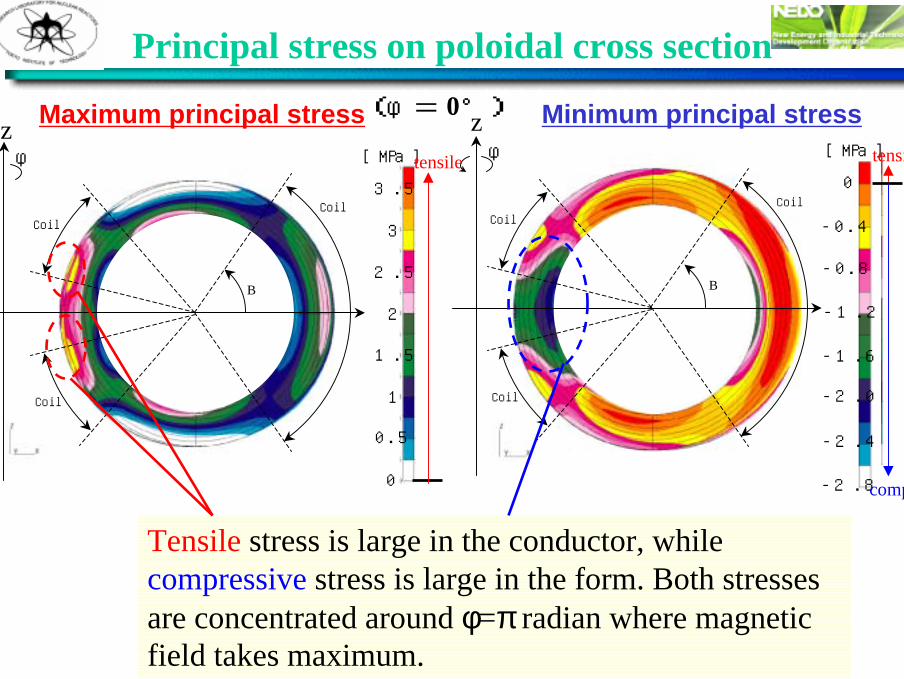
Principal stress on poloidal cross section
Maximum principal stress Minimum principal stress
Coil
Coil
Coil
θ
( φ= 0°)
Tensile stress is large in the conductor, while compressive stress is large in the form. Both stresses are concentrated around φ=π radian where magnetic field takes maximum.
[MPa]
-2.8
-2.4
-2.0
-1.6
-1.2
-0.8
-0.4
0
compres
tensileφ
z[MPa]
0
0.5
1
1.5
2
2.5
3
3.5
tensileφz

Summary I
• In order to verify the concept of the optimal coil to store magnetic energy based on the virial theorem, the device composed of a toroidal winding-form and two sets of helical coils wound on two layers was constructed.
• The experiments with the device show that our optimal coil (VLC) achieves the minimum and flat stress distribution, which is also obtained by the numerical calculations with the shell model.
• In order to complete the VLC concept, stress distribution is evaluated by FEM with a monolithic model, and good agreement with the experiment is obtained.

Summary II
• Compressive stress is produced mainly on the surface of the winding form where strains are measured, while tensile stress is produced mainly on the surface of the coil conductors.
• Stress distributions are quite different on inner and outer surfaces. Compressive stress is mainly produced in the shell region, and large compressive stress is produced around inner region where magnetic field takes the maximum value.
• A dense winding of coil conductors is required to reduce the compressive stress which is unfavorable for SMES.
FEM analysis shows that;