
FEASIBILITY STUDY OF LNG PRE COOLING …umpir.ump.edu.my/3189/1/CD5589_NORSHAHIDA__RAHMAN.pdf ·...
26
FEASIBILITY STUDY OF LNG PRE – COOLING SYSTEM USING CARBON DIOXIDE AS A REFRIGERANT NORSHAHIDA BINTI RAHMAN A thesis submitted in fulfillment of the requirements for the award of the degree of Bachelor of Chemical Engineering (Gas Technology) Faculty of Chemical & Natural Resources Engineering Universiti Malaysia Pahang MARCH 2011
Transcript of FEASIBILITY STUDY OF LNG PRE COOLING …umpir.ump.edu.my/3189/1/CD5589_NORSHAHIDA__RAHMAN.pdf ·...

FEASIBILITY STUDY OF LNG PRE – COOLING SYSTEM USING CARBON
DIOXIDE AS A REFRIGERANT
NORSHAHIDA BINTI RAHMAN
A thesis submitted in fulfillment
of the requirements for the award of the degree of
Bachelor of Chemical Engineering (Gas Technology)
Faculty of Chemical & Natural Resources Engineering
Universiti Malaysia Pahang
MARCH 2011
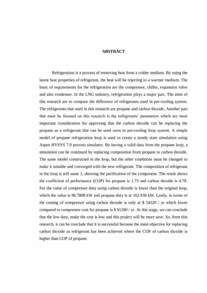
ABSTRACT
Refrigeration is a process of removing heat from a colder medium. By using the
latent heat properties of refrigerant, the heat will be rejecting to a warmer medium. The
basic of requirements for the refrigeration are the compressor, chiller, expansion valve
and also condenser. In the LNG industry, refrigeration plays a major part. The aims of
this research are to compare the difference of refrigerants used in pre-cooling system.
The refrigerants that used in this research are propane and carbon dioxide. Another part
that must be focused on this research is the refrigerants‟ parameters which are most
important consideration for approving that the carbon dioxide can be replacing the
propane as a refrigerant that can be used soon in pre-cooling loop system. A simple
model of propane refrigeration loop is used to create a steady state simulation using
Aspen HYSYS 7.0 process simulator. By having a valid data from the propane loop, a
simulation can be continued by replacing composition from propane to carbon dioxide.
The same model constructed in the loop, but the other conditions must be changed to
make it suitable and converged with the new refrigerant. The composition of refrigerant
in the loop is still same 1, showing the purification of the component. The result shows
the coefficient of performance (COP) for propane is 1.73 and carbon dioxide is 4.78.
For the value of compressor duty using carbon dioxide is lower than the original loop,
which the value is 96.7808 kW and propane duty is at 162.938 kW. Lastly, in terms of
the costing of compressor using carbon dioxide is only at $ 54320 / yr which lower
compared to compressor cost for propane is $ 91280 / yr. At this stage, we can conclude
that the low duty, make the cost is low and this project will be more save. So, from this
research, it can be conclude that it is successful because the main objective for replacing
carbon dioxide as refrigerant has been achieved where the COP of carbon dioxide is
higher than COP of propane.
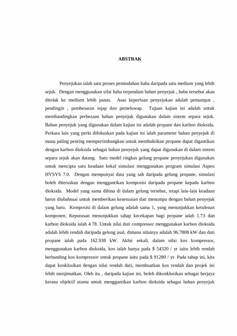
ABSTRAK
Penyejukan ialah satu proses pemindahan haba daripada satu medium yang lebih
sejuk. Dengan menggunakan sifat haba terpendam bahan penyejuk , haba tersebut akan
ditolak ke medium lebih panas. Asas keperluan penyejukan adalah pemampat ,
pendingin , pembesaran injap dan pemeluwap. Tujuan kajian ini adalah untuk
membandingkan perbezaan bahan penyejuk digunakan dalam sistem separa sejuk.
Bahan penyejuk yang digunakan dalam kajian ini adalah propane dan karbon dioksida.
Perkara lain yang perlu difokuskan pada kajian ini ialah parameter bahan penyejuk di
mana paling penting mempertimbangkan untuk membuktikan propane dapat digantikan
dengan karbon dioksida sebagai bahan penyejuk yang dapat digunakan di dalam sistem
separa sejuk akan datang. Satu model ringkas gelung propane penyejukan digunakan
untuk mencipta satu keadaan kekal simulasi menggunakan program simulasi Aspen
HYSYS 7.0. Dengan mempunyai data yang sah daripada gelung propane, simulasi
boleh diteruskan dengan menggantikan komposisi daripada propane kepada karbon
dioksida. Model yang sama dibina di dalam gelung tersebut, tetapi lain-lain keadaan
harus diubahsuai untuk memberikan kesesuaian dan menumpu dengan bahan penyejuk
yang baru. Komposisi di dalam gelung adalah sama 1, yang menunjukkan ketulenan
komponen. Keputusan menunjukkan tahap kecekapan bagi propane ialah 1.73 dan
karbon dioksida ialah 4.78. Untuk nilai duti compressor menggunakan karbon dioksida
adalah lebih rendah daripada gelung asal, dimana nilainya adalah 96.7808 kW dan duti
propane ialah pada 162.938 kW. Akhir sekali, dalam nilai kos kompressor,
menggunakan karbon dioksida, kos ialah hanya pada $ 54320 / yr iaitu lebih rendah
berbanding kos kompressor untuk propane iaitu pada $ 91280 / yr. Pada tahap ini, kita
dapat konklusikan dengan nilai rendah duti, membuatkan kos rendah dan projek ini
lebih menjimatkan. Oleh itu , daripada kajian ini, boleh dikonklusikan sebagai berjaya
kerana objektif utama untuk menggantikan karbon dioksida sebagai bahan penyejuk

terlaksana apabila nilai tahap kecekapan karbon dioksida lebih tinggi berbanding tahap
kecekapan propane.

TABLE OF CONTENTS
CHAPTER TITLE PAGE
RESEARCH TITLE I
DECLARATION II
DEDICATION III
ACKNOWLEDGEMENT IV
ABSTRACT V
ABSTRAK VI
TABLE OF CONTENT VIII
LIST OF TABLES XI
LIST OF FIGURES XII
NOMENCLATURES XIII
1 INTRODUCTION
1.1 Refrigeration 1
1.1.1 History of Refrigeration 2
1.1.2 Refrigeration System 3
1.1.3 Refrigeration Process Loop 3
1.2 Problem Statement 4
1.3 Objective 5
1.4 Scope of Study 6
1.5 Significance of Study 6

2 LITERATURE REVEW
2.1 The Discovery of Carbon Dioxide 7
2.2 Adaption Compressor for Carbon Dioxide 8
2.3 The Decline and Fall of Carbo Dioxide 8
2.4 Carbon Dioxide Future Possibilities 9
2.5 Refrigeration Cycle 10
2.6 Types of Compressor 12
2.6.1 Positive Displacement Compressor 13
2.6.2 Dynamic Compressor 16
2.7 Choice of Refrigerant 17
2.8 Previous Works 18
3 RESEARCH METHODOLOGY
3.1 Obtain A Flowsheet for LNG ( Liquefied Natural Gas ) Pre –
Cooling System 20
3.2 Modeling and Simulation of the Flwsheet 22
3.3 The Evaluation of Performance In Terms of Duty , Refrigerant ,
and Coefficient of performance (COP) 23
3.4 Substitution of Carbon Dioxide as Refrigerant in Propane
Refrigeration Loop 24
3.5 Identifying Controlling Factor 25
3.6 Modeling Assumptions 26
3.7 Summary of Research Methodology 27
4 RESULTS AND DISCUSSION
4.1 Aspen HYSYS Model of Refrigeration Loop 29
4.2 Results in Expansion Valve , Chiller , Compressor and Condenser
Unit 30
5 CONCLUSION AND RECOMMENDATION
5.1 Conclusion 34
5.2 Recommendation 35
REFERENCES 36
APPENDIXES 39

LIST OF TABLES
TABLE NO TITLE PAGE
3.1 Composition of Propane loop in streams 23
3.2 Composition of Carbon Dioxide loop in streams 24
4.1 Data of refrigerants in expansion valve unit 30
4.2 Data of refrigerants in chiller unit 31
4.3 Data of refrigerants in compressor unit 31
4.4 Data of refrigerants in condenser unit 32
4.5 Overall data of refrigerants in terms of duty in all
Unit operations 32

LIST OF FIGURES
FIGURE NO. TITLE PAGE
2.1 P – H chart 11
2.2 Reciprocating Compressor 14
2.3 Rotary Compressor 15
2.4 Centrifugal Compressor 16
2.5 T-S Diagram for Transcritical Carbon Dioxide Cycle 19
3.1 HYSYS model for propane pre – cooling refrigeration
loop 22
3.2 Summary of Research Methodology 28
4.1 Aspen HYSYS model of Carbon Dioxide refrigeration 30
loop
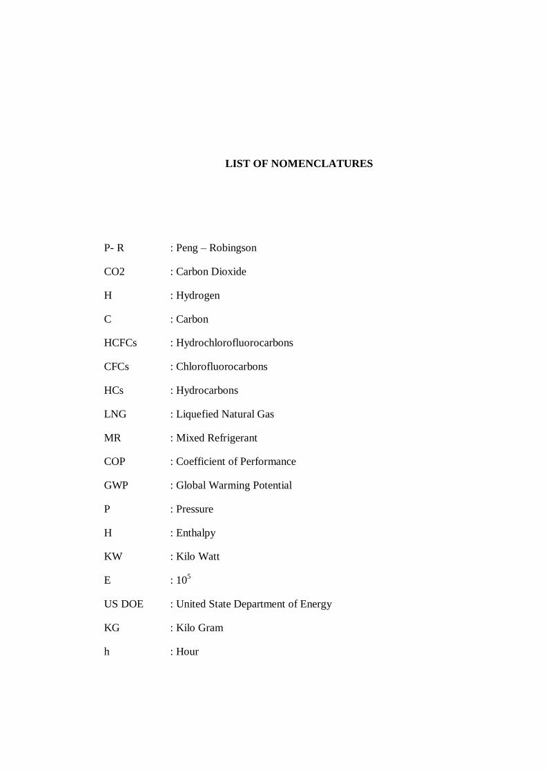
LIST OF NOMENCLATURES
P- R : Peng – Robingson
CO2 : Carbon Dioxide
H : Hydrogen
C : Carbon
HCFCs : Hydrochlorofluorocarbons
CFCs : Chlorofluorocarbons
HCs : Hydrocarbons
LNG : Liquefied Natural Gas
MR : Mixed Refrigerant
COP : Coefficient of Performance
GWP : Global Warming Potential
P : Pressure
H : Enthalpy
KW : Kilo Watt
E : 105
US DOE : United State Department of Energy
KG : Kilo Gram
h : Hour

J – T : Joule – Thompson
kPa : Kilo Pascal
˚C : Degree Celcius

CHAPTER 1
INTRODUCTION
1.1 Refrigeration
Industrial refrigeration systems are widely used for gas liquefaction, food
processing, food preservation chemical production and numerous other special
applications in the construction and manufacturing industries (by K.A Manske, 2001). A
process which removing heat form a substance is called as a refrigeration process. It
will reject the heat and will remove to the atmosphere at a high temperature level. Heat
flows from a body at a high temperature to another at a low temperature level. An
external energy is required and important which is for the heat flow from the lower to
higher energy level. While refrigerant is the medium for carrying heat. It is needed
during their cycle in the refrigeration system. Heat will be absorbed at low temperature
level and removed at a higher level. Refrigerants are come from two molecules,
methane and ethane. These two molecules simply contain hydrogen (H) and carbon (C)
is referred to as pure hydrocarbons (HCs).
1.1.1 History of Refrigeration
In 1550, the word of refrigerate was introduced when a method was
found as the addition of chemicals , such as sodium nitrate or potassium nitrate
into water causes that the temperature to fall. The American physician, John
Gorrie, had designed and built a tool for air – cooling, which the aim for this
invention is for treating yellow – fever patients. The basic of his invention is
same like the basic principle of refrigerators that often used in nowadays. By
using compression level, the gas was cooling by sending through the radiating
coils and expanding process will take part which is functioned for lowering
temperature level. He was granted the first U.S Patent for mechanical
refrigeration in 1851. After that, the starting of refrigeration was taken part in
refrigerated cars which were used to transport milk and butter in 1840.
In 1850, brewing was the initial activity that using mechanical
refrigeration. The process was used the basic of absorption and which firstly
used by S. Liebmann‟s Song Brewing Company in 1870 that placed Brooklyn,
New York. “Good sources were harder and harder to find. By the 1890 „s natural
ice became a problem because of pollution and sewage dumping.” This stated by
co – author of Heat and Cold: Mastering the Great Indoors, Bern Nagengast.
(Published by the American Society of Heating, Refrigeration and Air –
conditioning Engineers). This was referred to the ice, which was used as the
refrigeration agent, which at the end becoming as a health problem. The first
signed was proved in the brewing industry.
1.1.2 Refrigeration System
There are several different of refrigeration systems which are
being used for the production of LNG (Liquefied Natural Gas). These include
mixed refrigerant processes such as mixed refrigerant (MR). In the pre-cooling
cycle, the treated natural gas and mixed refrigerant (MR) of the main
liquefaction cycle are cooled to a temperature of about -50˚C. The pre cool
refrigerant is primarily mixture of ethane and propane. The pre-cooling cycle is
two stages and uses spool wound heat exchangers, since the liquid pre-cool MR
evaporates over a temperature range rather than at one temperature, similarly
like case of propane. The pre-cool MR is compressed in a two stage air-cooled
centrifugal compressor.
1.1.3 Refrigeration Process Loop
In a refrigeration process loop, there are five basic things that
must be involved. The four important things are the unit operations. The rest is
the refrigerant that will be used in the process. The first unit operation as an
initial for processing the refrigeration process is chiller or evaporator. This is
very important to remove the unwanted heat that coming from the product
through the liquid refrigerant. The second is by putting the compressor which
the role of this equipment for transforming the vapor form from the lower
temperature to the higher temperature and at the same time, the pressure level
also will be increasing. After the compressor, the condenser will be continue its

process by extracting the het that having in refrigerant to the air. The last part of
the loop is by continuing the process with an expansion valve. The function of
that valve is to send back the liquid refrigerant to the chiller.
1.2 Problem Statement
The use of CO2 as a refrigerant dates back more than a century, but it fell out of
favor in the air-conditioning and refrigeration industry with the development of
chlorofluorocarbons (CFCs) in the 1930s. However, when concerns about the depletion
of the stratospheric ozone layer emerged in the 1970‟s national and international
agreements were enacted to phase out CFCs and HCFCs (hydrochlorofluorocarbons).
Carbon dioxide is non-flammable and non-toxic in contrast to other natural refrigerants.
Centralized refrigeration systems used in supermarkets are prone to leakage due
to the large number of refrigerant line joints, long runs of refrigerant piping, and
frequent thermal cycling. Carbon dioxide can be used efficiently in these systems, and
some leakage can be tolerated. However there is a downside to using CO2 as a
refrigerant. Many studies, both theoretical and experimental, have demonstrated that the
thermodynamic efficiency of CO2 cycles is lower than that of conventional
fluorocarbon-based vapor compression systems, particularly at high ambient
temperatures.

In this research, feasibility study is done whether the carbon dioxide can be used
as refrigerant while at the same time CO2 emission can be reduced. The other focus is
by trying to make it more environmental friendly in refrigeration system. In the
refrigeration requirement, one of the most important things that must be focused
carefully is the value of its coefficient of performance (COP) that must be in higher
level which can be the best refrigerant. This COP is important which will show its
efficiency in the process.
The next part of that is by having low duty in compressor unit. By lowering the
duty, the cost of compressor also will be decreasing as what like the formula of
calculation for compressor cost is taking the duty value from compressor. Therefore,
when the lower duty, the process will be more save because of decreasing its cost.
1.3 Objectives
Objective of this study is to perform simulation study in using carbon dioxide as
a suitable pre-cooling refrigerant for LNG production by using Aspen HYSYS. This
simulation will be trying with two different of refrigerants that starting with propane
and next is using carbon dioxide. After that the comparison between these two
refrigerants will be done.

1.4 Scopes of Study
In this research, there are several parts or characteristics of best refrigerant will
be in consideration to compare which refrigerant is the best by comparing its coefficient
of performance (COP), the value of compressor duty and its compressor cost that will
be one of the main requirements in choosing refrigerant in industry which will give the
best efficiency and low cost to make the industrial operation more save.
1.5 Significance of Study
Through this study, there are several of advantages by having this research
which the characteristics of refrigerant can be understand completely, the requirements
that must be considered in choosing refrigerant and also the basic of refrigeration cycle
can be known by knowing its basic components that every process in refrigeration has
their own function through the certain condition that effecting the flow of liquid
refrigerant in refrigeration loop. Another part of this research is to reduce the emission
of carbon dioxide where by replacing the carbon dioxide as a refrigerant.
CHAPTER 2
LITERATURE REVIEW
2.1 The Discovery of Carbon Dioxide
In the vapor compression, carbon dioxide has been used as refrigerant for over
130 years. The new techniques that involving this refrigerant just be found last decade
which to exploit the uniquely advantages properties of carbon dioxide. In the 18 th
century the initial steps were found by two Scots physicians, Dr William Cullen and Dr
James Black. From the experiment by Black, led him to the exploration of carbon
dioxide which had been given called as “fixed air“. The further experiment showed that
this carbon dioxide had involved in burning and breathing processes. The prediction of
that “fixed air” present only in small portion in atmosphere was correct which the level
was 0.03 %. Neither Cullen nor Black was primarily interested in thermodynamics or
refrigeration, and their ideas not developed for nearly a century (Thevenot, 1979).

2.2 Adaption Compressor for Carbon Dioxide
From the work of Thaddeus Lowe in Texas, carbon dioxide was the next to
make breakthrough. He was a scientist that responsible for founding of Union Army‟s
Observation Corps in 1861. In 1860, he developed a compressor which then adapted for
Carbon Dioxide in 1866. It was then used for the manufacture of artificial ice. In 20
years then, a suggestion was made that his system which to produce “dry ice” was in an
open system. However there is no doubt that his British Patent, number 952, of 1867
(Newton, 1867) discloses a closed vapor compression cycle.
2.3 The Decline and Fall of Carbon Dioxide
In the 1880‟s carbon dioxide became a well – known refrigerant because of its
efficiency that more efficient than the open – circuit air cycle system and reliable. There
are some listed of advantages of „liquid carbonic acid‟ which including “being already
much cheaper than nearly all chemicals used as yet in ice – machines” (H. Lake, 1884)
and also stated that “cold, of almost any low degree can be produced” and “in case of
leakage, no more or less unpleasant gases which are deleterious to health enter the work
room” (F. Windhausen, 1886). This only contemporary early carbon dioxide systems
report was not „unparalleled‟ quality level. Carbon dioxide ever been used for ships
because it was safer, and reduced the seawater temperature level to 20 ˚C. In 1932, the
Frick Company in response to ongoing safety concerns about large ammonia charges,

started installing a hybrid system which used carbon dioxide for the low temperature
stage, with a much smaller ammonia plant providing the necessary refrigeration to
condense the carbon dioxide at moderate temperature and pressures (F. Kitzmiller,
1932).
2.4 Carbon Dioxide Future Possibilities
Some of the factor that fixing carbon dioxide is currently pressure. The
requirement in developing for an industrial system is should have a compressor that able
to operate at 50 bar g. This development in industrial field need not only for large
systems, but it will be able for engineer to comprise the carbon dioxide compressor. As
an additional, the system also must be updated by using the reverse cycle defrosting of
reduce temperature carbon dioxide evaporators, that will cause it suitable and can be
used for small freezers and low temperature cold stores.
One of the conclusion can be done during the 19 th
century, carbon dioxide was
probably the cheapest that a good refrigerant. In that time, the manufacturing was easy
to cope with the requirements, and an increased level of safety and the legislation which
can be one of the medium that helping to make carbon dioxide a preferred choice in
industrial systems in the near future.
2.5 Refrigeration Cycle
The refrigeration is simplified as the process of removing heat from the cold
medium and the heat will be rejected at the hot medium. During this removing and
rejection of heat, the temperature level of refrigerant will be different. In the process of
removing heat, refrigerant must have lower temperature level compared o the medium
to be cooled. While for the rejection part, the temperature for refrigerant must be higher
than its medium for rejecting heat. In the refrigeration cycle, there are five basic
components that must have in this cycle. The components are the evaporator or chiller,
compressor, condenser and also an expansion valve. The last is refrigerant that will be
used in the cycle.
A chart is an important part to understanding the cycle completely. The Figure
2.1 below shows the cycle involved in refrigeration cycle. In this P – H chart,
comparison is done between the pressure and enthalpy. From the P – H chart, the
horizontal line shows the constant in pressure and while the vertical line is shows the
constant in enthalpy. There are three regions or division in this chart. The sub cooled
region is at the left, the superheated region is at the right and lastly the wet region is at
the middle. The mixture region indicated for the constant temperature which the process
for changing phases will be done and the pressure also in constant. The regions which
stated “saturated vapor line” and “saturated liquid line” are for the saturated stated for
refrigerant.
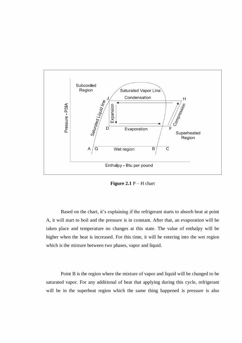
Figure 2.1 P – H chart
Based on the chart, it‟s explaining if the refrigerant starts to absorb heat at point
A, it will start to boil and the pressure is in constant. After that, an evaporation will be
taken place and temperature no changes at this state. The value of enthalpy will be
higher when the heat is increased. For this time, it will be entering into the wet region
which is the mixture between two phases, vapor and liquid.
Point B is the region where the mixture of vapor and liquid will be changed to be
saturated vapor. For any additional of heat that applying during this cycle, refrigerant
will be in the superheat region which the same thing happened is pressure is also

constant. This region is indicated by point C. In the evaporation, the refrigerant will be
entering into evaporator as the mixture of vapor and liquid phases which then absorbing
heat. At this stage, process changing of liquid to gas phase happened. Then the gas is
compressed from the low pressure to the high pressure.
On the compression process, the points of F and H showed the process
happened. Now, the condition is hot with high pressure then sending into condenser for
entering new process of “Total Heat of Rejection”. The heats that rejected are from the
compression and evaporation processes. From the chart, the condensation can be seen
through the constant of pressure. At the points H and J, heat transfer will be happened
because of the difference between the enthalpy. Lastly, at the point of J, this showing
that the refrigerant has totally condensed to liquid and the pressure is still constant.
2.6. Types of Compressor
There are several types of compressor that can be used. Industrial plants used the
compressor in their product operations. The U.S. Department of Energy (2003) has
reported that compressor and compressed air systems are very important in improving
the energies efficiency at industrial plant. System in the compressed air is containing of
compressor and treatment.
There are two basic compressor types, positive displacement and dynamic. In
the positive displacement type, a given quantity of air or gas is trapped in a compression
chamber and the volume it occupies is mechanically reduced, causing a corresponding
rise in pressure prior to discharge, in additional, the air flow remains essentially
constant at constant speed.(United States Department Of Energy, 2003).
For dynamic compressor, it is usually used for the continuous flowing air which
also used in gas by changing its velocity energy into pressure energy both by the
impellers and the eliminating of diffusers. In the centrifugal – type dynamic
compressors, the shape of the impeller blades determines the relationship between air
flow and the pressure (or head) generated (United State Department of Energy, 2003).
2.6.1 Positive Displacement Compressor
In the positive displacement compressor, there are two types that
available, the compressors are reciprocating and rotary. From the figure 2.2 below
shows the reciprocating compressor which is available for many configurations which
are widely used in horizontal, vertical, horizontal balance – opposed and tandem.
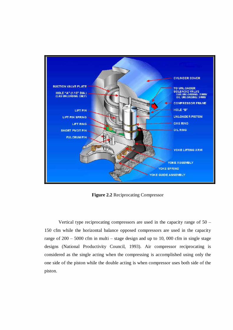
Figure 2.2 Reciprocating Compressor
Vertical type reciprocating compressors are used in the capacity range of 50 –
150 cfm while the horizontal balance opposed compressors are used in the capacity
range of 200 – 5000 cfm in multi – stage design and up to 10, 000 cfm in single stage
designs (National Productivity Council, 1993). Air compressor reciprocating is
considered as the single acting when the compressing is accomplished using only the
one side of the piston while the double acting is when compressor uses both side of the
piston.

For the next type of positive displacement compressor is the rotary type. In the
Figure 2.3 below shows the rotary compressor which can be operated at high speed and
provided more throughput if compared to reciprocating compressor.
Figure 2.3 Rotary Compressor
This kind of compressor having rotors in place of pistons and it also will give
the continuous for pulsation free discharge. In terms of cost and its weight, it is low and
very compact in the scope of size, and the most important part is easy to maintain. By
having these characteristics, it is the reason why rotary compressor is much known in
industry field. Usually it is used in the range between 22 to 150 kW.


