FEA calculation - Nikhef · The FEA analyses are performed using the software package...
16
FEA calculation Aluminum Inner Shell NIKHEF 11-0082C DeMaCo P100331 Client: DeMaCo Author: R. van Ruijven Checked: J.H. de Groot Doc.: 11-0082C-DOC01 Rev.: A Date: 23-03-2011
Transcript of FEA calculation - Nikhef · The FEA analyses are performed using the software package...

FEA calculation
Aluminum Inner Shell NIKHEF
11-0082C
DeMaCo P100331
Client: DeMaCo Author: R. van Ruijven Checked: J.H. de Groot
Doc.: 11-0082C-DOC01 Rev.: A Date: 23-03-2011

FEA calculation - Aluminum Inner Shell NIKHEF
DeMaCo 11-0082C-DOC01 Rev: A 23-03-2011
2 of 13
Table of contents
Summary....................................................................................................................... 3
Conclusion ..................................................................................................................... 3
1 Introduction .......................................................................................................... 4
2 Inner shell properties ............................................................................................. 4
2.1 Components .................................................................................................. 4
2.2 FEA analysis .................................................................................................. 5
2.3 Loads ........................................................................................................... 5
2.4 Material properties ......................................................................................... 5
2.5 Corrosion allowances ..................................................................................... 6
2.6 Load cases and evaluation of results ............................................................... 6
2.7 Additional external pressure check according AD2000 B6 .................................. 6
3 FEA model ............................................................................................................. 7
3.1 Loadcase 1: design ........................................................................................ 8
3.2 Loadcase 2: Full Vacuum .............................................................................. 10
3.3 Loadcase 3: Test ......................................................................................... 12
4 Results of external pressure check according AD2000 B6 ......................................... 13
Appendix 1: Drawing .................................................................................................... 13
Appendix 2: AD2000 B6 external pressure check ............................................................. 13
Revision Date By Checked Issue
A 23-03-2011 RvR HdG Fixation pins and load case pressure test added
0 21-03-2011 RvR HdG First release

FEA calculation - Aluminum Inner Shell NIKHEF
DeMaCo 11-0082C-DOC01 Rev: A 23-03-2011
3 of 13
Summary
DeMaCo has to design and fabricate an aluminum inner shell for cryogenic cooling for NIKHEF. In this report stresses are calculated using FEA software. These stresses are checked for compliance with AD 2000 D1 (internal pressure) and D6 (external pressure). Operating conditions:
Poperating = 1.5 barg Toperating = -196 to +100°C
Design limits operating:
Pdesign = 1.5 barg Tdesign = +150°C
Leakage testing:
Peakage test = -1.0 barg (Full Vacuum) Tleakage test = 20°C
Test pressure:
Ptest = 3.33 barg Ttest = 20°C
Weight of components:
Weight of vessel (517 kg ) Nitrogen liquid (216 kg distributed over internal surfaces). Bearing load in fixation 4 pins Ø10: 7330 / 4 pins = 1830 N each.
No nozzle loads are defined. Material type: Aluminum Al 5754 The computed stresses are compared with the maximum allowable stresses according to AD 2000.
Conclusion
The shell complies with the requirements of AD 2000

FEA calculation - Aluminum Inner Shell NIKHEF
DeMaCo 11-0082C-DOC01 Rev: A 23-03-2011
4 of 13
1 Introduction
DeMaCo has to design and fabricate an aluminum inner shell for cryogenic cooling for NIKHEF. In this report stresses are calculated using FEA software. These stresses are checked for compliance with AD 2000 D1 (internal pressure) and D6 (external pressure). All dimensions are in mm
2 Inner shell properties
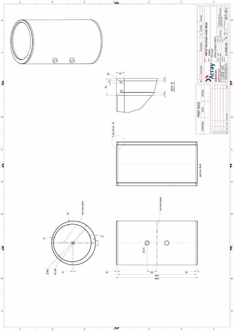
2.1 Components
The inner shell consists of two pipes with an 32 mm axis offset. Inner wall: I.D. Ø950 x 1980 x 15 mm Outer wall: O.D. Ø1120 x 1980 x 12 mm Baffle: thickness 40 mm Nozzle: DN100 x 3 Total weight of shell: 517 kg Total weight of Nitrogen liquid (density 800 kg/m3): 216 kg The vessel is fixed by two times two pins connected to the Baffles. See appendix 1 for a drawing of the model, directly generated from the model.
Figuur 1: FEA model (with two symmetry planes)
Fixation pins

FEA calculation - Aluminum Inner Shell NIKHEF
DeMaCo 11-0082C-DOC01 Rev: A 23-03-2011
5 of 13
2.2 FEA analysis
The FEA analyses are performed using the software package Pro/MECHANICA. The analyses are linear elastic, no plastic material behavior is incorporated. Only solid elements are used, with a maximum element order of 9 after the second calculation step. The 9th order polynomial describes the geometry and stresses with a high level of accuracy, instead of increasing the density of mesh elements like traditional FEA packages do. All analyses for this project are performed using solid elements.
2.3 Loads
Operating conditions:
Poperating = 1.5 barg Toperating = -196 to +100°C
Design limits operating:
Pdesign = 1.5 barg
Tdesign = +150°C Leakage testing:
Peakage test = -1.0 barg (Full Vacuum) Tleakage test = 20°C
Test pressure:
Ptest = 3.33 barg (PED: 1.25 * 80/45 * 1.5) Ttest = 20°C
No nozzle loads are defined. Weight of components:
Weight of vessel (517 kg ) Nitrogen liquid (216 kg distributed over internal surfaces). Bearing load in fixation 4 pins Ø10: 7330 / 4 pins = 1830 N each.
2.4 Material properties
Material type: Aluminum Al 5754 Materials according to AD 2000-Merkblatt W6/1, D1.2003 Temperatures valid between -270°C to + 150°C
Table 2: Al 5754 material properties according to AD 2000
Type and thickness Condition 0.2% limit -270 to 100 °C [N/mm2]
1.0% limit 150 °C [N/mm2]
Tensile strength [N/mm2]
Tube (0.3 to 10) 0/H111 80 45 180
Plate (25 to 50) H112 80 45 190

FEA calculation - Aluminum Inner Shell NIKHEF
DeMaCo 11-0082C-DOC01 Rev: A 23-03-2011
6 of 13
2.5 Corrosion allowances
Corrosion allowance is 0 mm.
2.6 Load cases and evaluation of results
With Pro/MECHANICA, stresses and displacement are computed. The stresses which are shown in the various figures the average stress by the definition of Von Mises. Load case 1 (Design) Primary load:
Pdesign = 1.5 barg Tdesign =+150°C
Weight of components (Weight of vessel and nitrogen. Fixation on 4 pins). Secondary load
No secondary loads Load case 2 (Full Vacuum) Primary load:
Pdesign = -1 barg (Full Vacuum) Tdesign = 20°C
Secondary load
No secondary loads Load case 3 (Hydro test)
Ptest = 3.33 barg Ttest = 20°C
Check According to AD 2000, the following set of checks must be evaluated:
1. σv;pm ≤ 1.0% yield stress / S with S (Sicherheitsbeiwert) according to AD2000 B0, table 2: S = 1.5 for normal conditions, S = 1.1 for pressure test
2.7 Additional external pressure check according AD2000 B6
The pressure vessel program BabsyWin is used to check buckling due to external pressure according to AD2000 B6 for both shells. Results can be found in appendix 2.

FEA calculation - Aluminum Inner Shell NIKHEF
DeMaCo 11-0082C-DOC01 Rev: A 23-03-2011
7 of 13
3 FEA model
Table 1: Components in FEA model
Component Material type Corrosion allowance
Effective wall thickness
Inner wall Tube 15 mm 0 mm 15 mm Outer wall Tube 12 mm 0 mm 12 mm Nozzle Tube 3 mm 0 mm 3 mm Baffle Plate 40 mm 0 mm 40 mm
The FEA model has two symmetry planes, one along the shell axis and one normal to the shell axis.
All elements are solid elements.

FEA calculation - Aluminum Inner Shell NIKHEF
DeMaCo 11-0082C-DOC01 Rev: A 23-03-2011
8 of 13
3.1 Loadcase 1: design
Table 2: Summary and evaluation of stresses
Load Maximum calculated stress Check (T=150°C) Result
σv;p 28 N/mm2 30 N/mm2 (1.0% yield/S) acceptable
Conclusion: the shell complies with the requirements of AD 2000
Figure 2: Displacement due to Primary loading (internal pressure). Maximum displacement 0.5 mm.
Figure 3: Primary loading (internal pressure only), von Mises stress. σv;pm,max = 28 N/mm2

FEA calculation - Aluminum Inner Shell NIKHEF
DeMaCo 11-0082C-DOC01 Rev: A 23-03-2011
9 of 13
Figure 4: Primary loading (internal pressure only), detail of ring, σv;pm,max = 20 N/mm2
Figure 5: Primary loading (internal pressure only), detail of nozzle and pin holes
σv;pm,max = 28 N/mm2
FEA calculation - Aluminum Inner Shell NIKHEF
DeMaCo 11-0082C-DOC01 Rev: A 23-03-2011
10 of 13
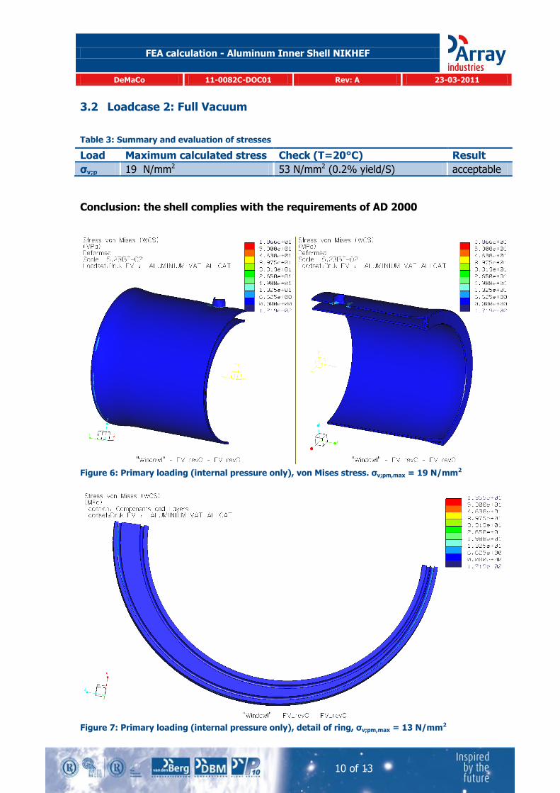
3.2 Loadcase 2: Full Vacuum
Table 3: Summary and evaluation of stresses
Load Maximum calculated stress Check (T=20°C) Result
σv;p 19 N/mm2 53 N/mm2 (0.2% yield/S) acceptable
Conclusion: the shell complies with the requirements of AD 2000
Figure 6: Primary loading (internal pressure only), von Mises stress. σv;pm,max = 19 N/mm2
Figure 7: Primary loading (internal pressure only), detail of ring, σv;pm,max = 13 N/mm2
FEA calculation - Aluminum Inner Shell NIKHEF
DeMaCo 11-0082C-DOC01 Rev: A 23-03-2011
11 of 13
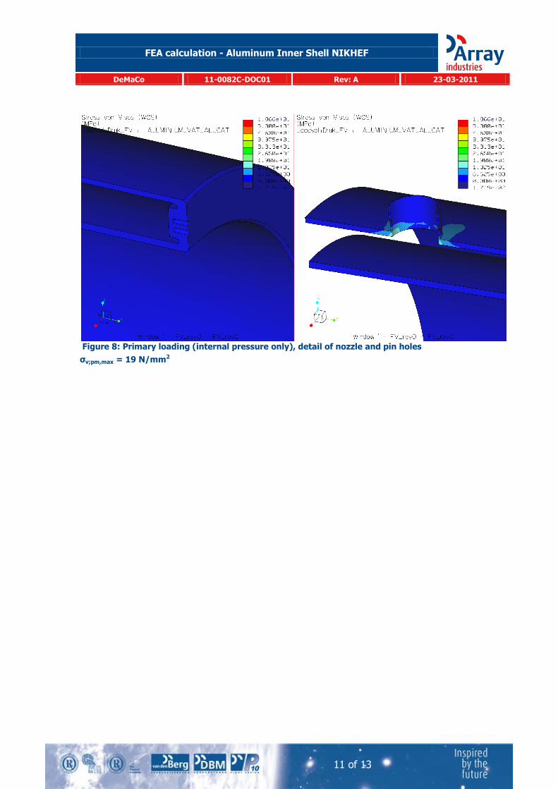
Figure 8: Primary loading (internal pressure only), detail of nozzle and pin holes
σv;pm,max = 19 N/mm2
FEA calculation - Aluminum Inner Shell NIKHEF
DeMaCo 11-0082C-DOC01 Rev: A 23-03-2011
12 of 13
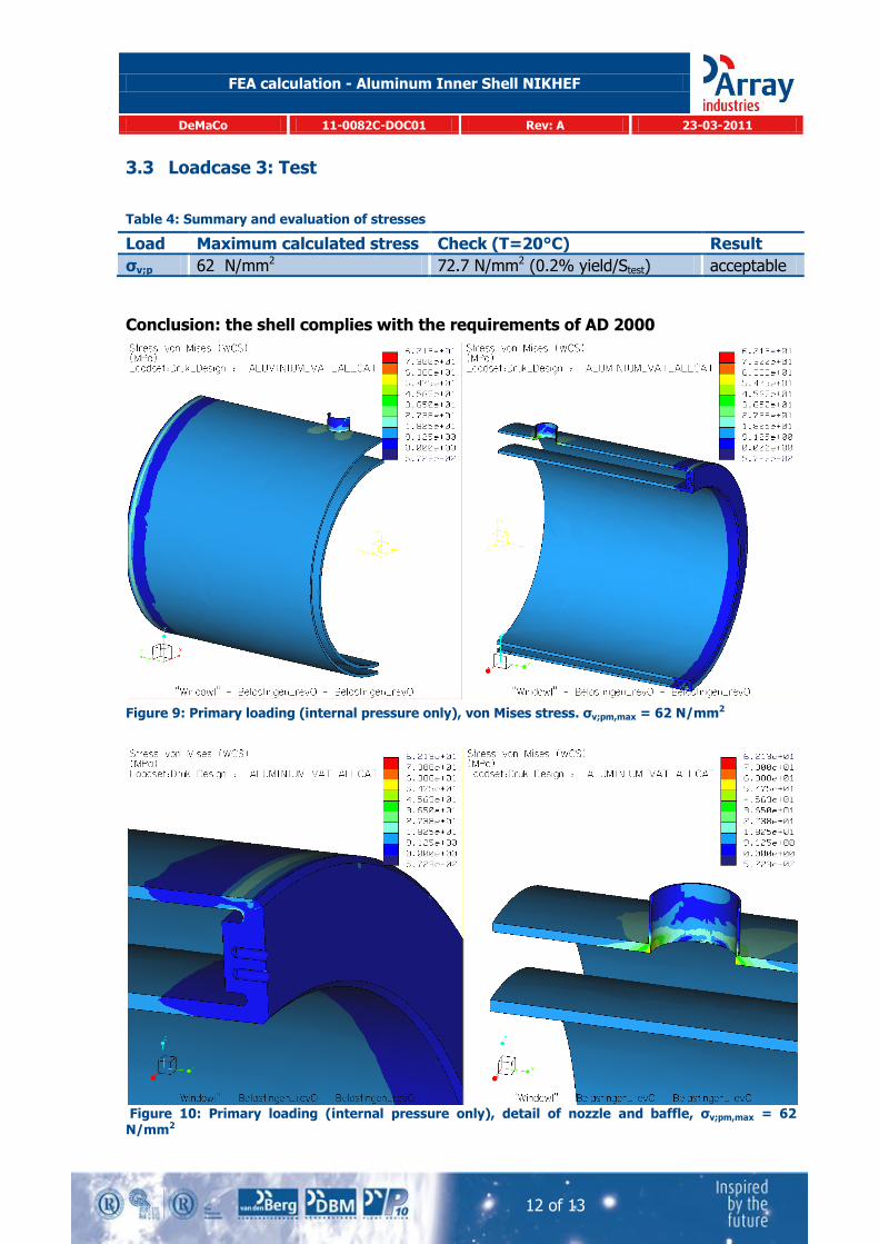
3.3 Loadcase 3: Test
Table 4: Summary and evaluation of stresses
Load Maximum calculated stress Check (T=20°C) Result
σv;p 62 N/mm2 72.7 N/mm2 (0.2% yield/Stest) acceptable
Conclusion: the shell complies with the requirements of AD 2000
Figure 9: Primary loading (internal pressure only), von Mises stress. σv;pm,max = 62 N/mm2
Figure 10: Primary loading (internal pressure only), detail of nozzle and baffle, σv;pm,max = 62 N/mm2
FEA calculation - Aluminum Inner Shell NIKHEF
DeMaCo 11-0082C-DOC01 Rev: A 23-03-2011
13 of 13
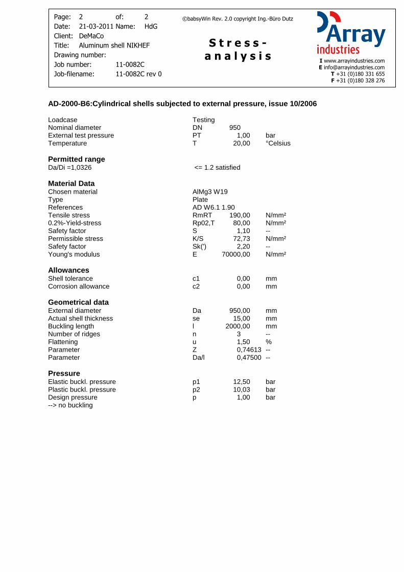
4 Results of external pressure check according AD2000 B6
The results of the pressure vessel program BabsyWin in appendix 2 show that the outer vessel is able to withstand an external pressure of 5.4 barg, the inner shell 10 barg according to AD2000 B6 with a safety factor S=1.1 (test condition).
Appendix 1: Drawing
See document: 11-0082C Aluminum Inner Shell NIKHEF rev 0 Appendix 1.pdf
Appendix 2: AD2000 B6 external pressure check
See document: 11-0082C Aluminum Inner Shell NIKHEF rev 0 Appendix 2.pdf

Page: 1 of: 2
Date: 17-03-2010 Name: RvdP
Client: DeMaCo
Title: STD FS 12 bar
Drawing number: 30030
Job number: 270039
Job-filename: AD_STD_12bar.job2
I www.arrayindustries.com E [email protected] T +31 (0)180 331 655 F +31 (0)180 328 276
S t r e s s - a n a l y s i s
©babsyWin Rev. 2.0 copyright Ing.-Büro Dutz Page: 1 of: 2
Date: 16-03-2010 Name: HdG
Client: IBS - MOT
Title: 42inch leiding
Drawing number:
Job number:
Job-filename:
I www.arrayindustries.com E [email protected] T +31 (0)180 331 655 F +31 (0)180 328 276
S t r e s s - a n a l y s i s
©babsyWin Rev. 2.0 copyright Ing.-Büro Dutz Page: 1 of: 2
Date: 16-07-2010 Name: HdG
Client: Cryonorm
Title: CNLP 7x8x10000 S Vaporiser
Drawing number: CN2100130-10
Job number: 10-0363C
Job-filename: Rev 0.job2
I www.arrayindustries.com E [email protected] T +31 (0)180 331 655 F +31 (0)180 328 276
S t r e s s - a n a l y s i s
©babsyWin Rev. 2.0 copyright Ing.-Büro Dutz Page: 1 of: 2
Date: Name:
Client:
Title:
Drawing number:
Job number:
Job-filename:
I www.arrayindustries.com E [email protected] T +31 (0)180 331 655 F +31 (0)180 328 276
S t r e s s - a n a l y s i s
©babsyWin Rev. 2.0 copyright Ing.-Büro Dutz Page: 1 of: 2
Date: 23-07-2010 Name: HdG
Client: GE Jenbacher
Title: Flange Calculation JMS 616
Drawing number: DN 800 eigen flens
Job number: 09-0210P
Job-filename:
I www.arrayindustries.com E [email protected] T +31 (0)180 331 655 F +31 (0)180 328 276
S t r e s s - a n a l y s i s
©babsyWin Rev. 2.0 copyright Ing.-Büro Dutz Page: 1 of: 2
Date: 21-03-2011 Name: HdG
Client: DeMaCo
Title: Aluminum shell NIKHEF
Drawing number:
Job number: 11-0082C
Job-filename: 11-0082C rev 0
I www.arrayindustries.com E [email protected] T +31 (0)180 331 655 F +31 (0)180 328 276
S t r e s s - a n a l y s i s
©babsyWin Rev. 2.0 copyright Ing.-Büro Dutz
AD-2000-B6:Cylindrical shells subjected to external pressure, issue 10/2006 Loadcase Testing Nominal diameter DN 1100 External test pressure PT 1,00 bar Temperature T 20,00 °Celsius
Permitted range Da/Di =1,0219 <= 1.2 satisfied
Material Data Chosen material AlMg3 W19 Type Plate References AD W6.1 1.90 Tensile stress RmRT 190,00 N/mm² 0.2%-Yield-stress Rp02,T 80,00 N/mm² Safety factor S 1,10 -- Permissible stress K/S 72,73 N/mm² Safety factor Sk(') 2,20 -- Young's modulus E 70000,00 N/mm²
Allowances Shell tolerance c1 0,00 mm Corrosion allowance c2 0,00 mm
Geometrical data External diameter Da 1120,00 mm Actual shell thickness se 12,00 mm Buckling length l 2000,00 mm Number of ridges n 4 -- Flattening u 1,50 % Parameter Z 0,87965 -- Parameter Da/l 0,56000 --
Pressure Elastic buckl. pressure p1 5,67 bar Plastic buckl. pressure p2 5,44 bar Design pressure p 1,00 bar --> no buckling
Page: 2 of: 2
Date: 17-03-2010 Name: RvdP
Client: DeMaCo
Title: STD FS 12 bar
Drawing number: 30030
Job number: 270039
Job-filename: AD_STD_12bar.job2
I www.arrayindustries.com E [email protected] T +31 (0)180 331 655 F +31 (0)180 328 276
S t r e s s - a n a l y s i s
©babsyWin Rev. 2.0 copyright Ing.-Büro Dutz Page: 2 of: 2
Date: 16-03-2010 Name: HdG
Client: IBS - MOT
Title: 42inch leiding
Drawing number:
Job number:
Job-filename:
I www.arrayindustries.com E [email protected] T +31 (0)180 331 655 F +31 (0)180 328 276
S t r e s s - a n a l y s i s
©babsyWin Rev. 2.0 copyright Ing.-Büro Dutz Page: 2 of: 2
Date: 16-07-2010 Name: HdG
Client: Cryonorm
Title: CNLP 7x8x10000 S Vaporiser
Drawing number: CN2100130-10
Job number: 10-0363C
Job-filename: Rev 0.job2
I www.arrayindustries.com E [email protected] T +31 (0)180 331 655 F +31 (0)180 328 276
S t r e s s - a n a l y s i s
©babsyWin Rev. 2.0 copyright Ing.-Büro Dutz Page: 2 of: 2
Date: Name:
Client:
Title:
Drawing number:
Job number:
Job-filename:
I www.arrayindustries.com E [email protected] T +31 (0)180 331 655 F +31 (0)180 328 276
S t r e s s - a n a l y s i s
©babsyWin Rev. 2.0 copyright Ing.-Büro Dutz Page: 2 of: 2
Date: 23-07-2010 Name: HdG
Client: GE Jenbacher
Title: Flange Calculation JMS 616
Drawing number: DN 800 eigen flens
Job number: 09-0210P
Job-filename:
I www.arrayindustries.com E [email protected] T +31 (0)180 331 655 F +31 (0)180 328 276
S t r e s s - a n a l y s i s
©babsyWin Rev. 2.0 copyright Ing.-Büro Dutz Page: 2 of: 2
Date: 21-03-2011 Name: HdG
Client: DeMaCo
Title: Aluminum shell NIKHEF
Drawing number:
Job number: 11-0082C
Job-filename: 11-0082C rev 0
I www.arrayindustries.com E [email protected] T +31 (0)180 331 655 F +31 (0)180 328 276
S t r e s s - a n a l y s i s
©babsyWin Rev. 2.0 copyright Ing.-Büro Dutz
AD-2000-B6:Cylindrical shells subjected to external pressure, issue 10/2006 Loadcase Testing Nominal diameter DN 950 External test pressure PT 1,00 bar Temperature T 20,00 °Celsius
Permitted range Da/Di =1,0326 <= 1.2 satisfied
Material Data Chosen material AlMg3 W19 Type Plate References AD W6.1 1.90 Tensile stress RmRT 190,00 N/mm² 0.2%-Yield-stress Rp02,T 80,00 N/mm² Safety factor S 1,10 -- Permissible stress K/S 72,73 N/mm² Safety factor Sk(') 2,20 -- Young's modulus E 70000,00 N/mm²
Allowances Shell tolerance c1 0,00 mm Corrosion allowance c2 0,00 mm
Geometrical data External diameter Da 950,00 mm Actual shell thickness se 15,00 mm Buckling length l 2000,00 mm Number of ridges n 3 -- Flattening u 1,50 % Parameter Z 0,74613 -- Parameter Da/l 0,47500 --
Pressure Elastic buckl. pressure p1 12,50 bar Plastic buckl. pressure p2 10,03 bar Design pressure p 1,00 bar --> no buckling