FCC DoC TEST REPORT - Logitech Report for... · FCC DoC TEST REPORT REPORT NO. : FD980710H04A MODEL...
61
Report No.: FD980710H04A 1 Report Format Version 3.0.0 Reference No.: 981201H02 FCC DoC TEST REPORT REPORT NO. : FD980710H04A MODEL NO. : N-I0003 RECEIVED : July 10, 2009 TESTED : July 14, 2009 and Dec. 02 to 03, 2009 ISSUED: Dec. 10, 2009 APPLICANT : LOGITECH FAR EAST LTD. ADDRESS : #2 Creation Rd. 4, Science-Based Ind. Park Hsinchu Taiwan, R.O.C. ISSUED BY : Bureau Veritas Consumer Products Services (H.K.) Ltd., Taoyuan Branch LAB LOCATION : No. 81-1, Lu Liao Keng, 9th Ling,Wu Lung Tsuen, Chiung Lin Hsiang, Hsin Chu Hsien 307, Taiwan This test report consists of 48 pages in total. It may be duplicated completely for legal use with the approval of the applicant. It should not be reproduced except in full, without the written approval of our laboratory. The client should not use it to claim product endorsement by TAF, NVLAP or any government agencies. The test results in the report only apply to the tested sample.
-
Upload
truongnguyet -
Category
Documents
-
view
216 -
download
2
Transcript of FCC DoC TEST REPORT - Logitech Report for... · FCC DoC TEST REPORT REPORT NO. : FD980710H04A MODEL...

Report No.: FD980710H04A 1 Report Format Version 3.0.0 Reference No.: 981201H02
FCC DoC TEST REPORT
REPORT NO. : FD980710H04A
MODEL NO. : N-I0003
RECEIVED : July 10, 2009
TESTED : July 14, 2009 and Dec. 02 to 03, 2009
ISSUED: Dec. 10, 2009
APPLICANT : LOGITECH FAR EAST LTD.
ADDRESS : #2 Creation Rd. 4, Science-Based Ind. Park Hsinchu Taiwan, R.O.C.
ISSUED BY : Bureau Veritas Consumer Products Services (H.K.) Ltd., Taoyuan Branch
LAB LOCATION : No. 81-1, Lu Liao Keng, 9th Ling,Wu Lung Tsuen, Chiung Lin Hsiang, Hsin Chu Hsien 307, Taiwan
This test report consists of 48 pages in total. It may be duplicated completely for legal use with the approval of the applicant. It should not be reproduced except in full, without the written approval of our laboratory. The client should not use it to claim product endorsement by TAF, NVLAP or any government agencies. The test results in the report only apply to the tested sample.

Report No.: FD980710H04A 2 Report Format Version 3.0.0 Reference No.: 981201H02
Table of Contents 1 CERTIFICATION............................................................................................. 3
2 SUMMARY OF TEST RESULTS..................................................................... 4 2.1 MEASUREMENT UNCERTAINTY .................................................................. 4
3 GENERAL INFORMATION ............................................................................. 5 3.1 GENERAL DESCRIPTION OF EUT................................................................ 5 3.2 GENERAL DESCRIPTION OF TEST MODE .................................................. 6 3.3 DESCRIPTION OF SUPPORT UNITS............................................................ 7 3.4 CONFIGURATION OF SYSTEM UNDER TEST............................................. 9 4 EMISSION TEST........................................................................................... 11
4.1 CONDUCTED EMISSION MEASUREMENT .................................................11 4.1.1 LIMITS OF CONDUCTED EMISSION MEASUREMENT...............................11 4.1.2 TEST INSTRUMENTS ...................................................................................11 4.1.3 TEST PROCEDURE ..................................................................................... 13 4.1.4 DEVIATION FROM TEST STANDARD ......................................................... 13 4.1.5 TEST SETUP ................................................................................................ 13 4.1.6 EUT OPERATING CONDITIONS.................................................................. 14 4.1.7 TEST RESULTS............................................................................................ 15 4.2 RADIATED EMISSION MEASUREMENT ..................................................... 23 4.2.1 LIMITS OF RADIATED EMISSION MEASUREMENT................................... 23 4.2.2 TEST INSTRUMENTS .................................................................................. 24 4.2.3 TEST PROCEDURE ..................................................................................... 26 4.2.4 DEVIATION FROM TEST STANDARD ......................................................... 26 4.2.5 TEST SETUP ................................................................................................ 27 4.2.6 EUT OPERATING CONDITIONS.................................................................. 27 4.2.7 TEST RESULTS............................................................................................ 28
5 PHOTOGRAPHS OF THE TEST CONFIGURATION.................................... 38
6 INFORMATION ON THE TESTING LABORATORIES .................................. 47
7 APPENDIX A - MODIFICATIONS RECORDERS FOR ENGINEERING CHANGES TO THE EUT BY THE LAB......................................................... 48

Report No.: FD980710H04A 3 Report Format Version 3.0.0 Reference No.: 981201H02
1 CERTIFICATION
PRODUCT : Remote control Harmony 700, Remote control Harmony 650, Remote control Harmony 600
BRAND NAME : Logitech MODEL NO. : N-I0003
TESTED : July 14, 2009 and Dec. 02 to 03, 2009 (For new samples test)
TEST SAMPLE : ENGINEERING SAMPLE APPLICANT : LOGITECH FAR EAST LTD.
STANDARDS : FCC Part 15, Subpart B, Class B CISPR 22: 1997, Class B ICES-003: 2004, Class B ANSI C63.4-2003
The above equipment (Model: N-I0003) has been tested by Bureau Veritas Consumer Products Services (H.K.) Ltd., Taoyuan Branch, and found compliance with the requirement of the above standards. The test record, data evaluation & Equipment Under Test (EUT) configurations represented herein are true and accurate accounts of the measurements of the sample’s EMC characteristics under the conditions specified in this report.
PREPARED BY : , DATE: Dec. 07, 2009 ( Claire Kuan, Specialist )
TECHNICAL ACCEPTANCE
:
, DATE: Dec. 07, 2009 ( Ray Yeh, Deputy Manager )
APPROVED BY :
, DATE: Dec. 07, 2009
( May Chen, Deputy Manager )
Report No.: FD980710H04A 4 Report Format Version 3.0.0 Reference No.: 981201H02
2 SUMMARY OF TEST RESULTS
Standard Test Type Result Remarks
Conducted Test PASS Meets Class B Limit Minimum passing margin is -9.06 dB at 0.150 MHz
FCC Part 15 Subpart B, Class B CISPR 22: 1997, Class B
ICES-003: Class B
Radiated Test PASS Meets Class B Limit Minimum passing margin is -5.36 dB at 223.30 MHz
Note: The limit for radiated test was performed according to CISPR 22, which was specified in FCC
PART 15 Subpart B 15.109(g). Also the limits of ICES-003: 2004 and CISPR 22 are same.
2.1 MEASUREMENT UNCERTAINTY Where relevant, the following measurement uncertainty levels have been estimated for tests performed on the EUT as specified in CISPR 16-4-2: This uncertainty represents an expanded uncertainty expressed at approximately the 95% confidence level using a coverage factor of k=2.
Measurement Value Conducted emissions 2.45 dB Radiated emissions(30MHz-1GHz) 3.83 dB

Report No.: FD980710H04A 5 Report Format Version 3.0.0 Reference No.: 981201H02
3 GENERAL INFORMATION 3.1 GENERAL DESCRIPTION OF EUT
PRODUCT Remote control Harmony 700, Remote control Harmony 650, Remote control Harmony 600
MODEL NO. N-I0003
POWER SUPPLY DC 5V from adapter, DC 5V from host equipment or DC 3V from batteries
POWER CORD NA DATA CABLE SUPPLIED
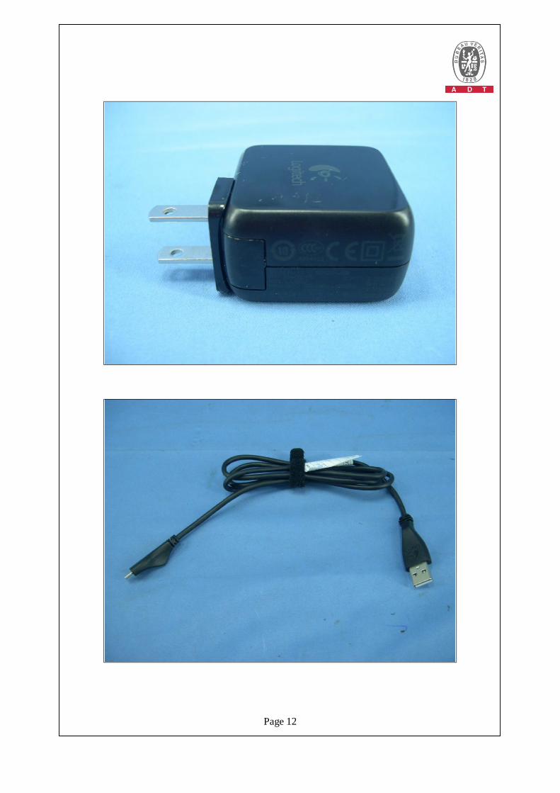
JEM recharge USB cable (Shielded, 1m) Sinbon recharge USB cable (Shielded, 1m)
I/O PORT USB port x 1
ASSOCIATED DEVICES
JEM recharge USB cable (Shielded, 1m) x 1 Sinbon recharge USB cable (Shielded, 1m) x 1 Adapter x 1
NOTE:
1. This report is a supplementary report of the following original report: u FD980710H04: Issued on July 27, 2009
The difference compared with the report is as the following below:
u Add new product names as following information:
Original product Sample Product Model Description
Sample 1 Remote control Harmony 700 N-I0003
1. Harmony 700 use the rechargeable battery 2. The different paint of top case as picture. 3. The LCM of Harmony 700 is color mode
Newly product Sample Product Model Description
Sample 2 Remote control Harmony 650
1. Harmony 650 use alkaline batter 2. The different paint of top case as picture. 3. The LCM of Harmony 650 is color mode
Sample 3 Remote control Harmony 600
N-I0003 1. Harmony 600 use alkaline battery 2. The different paint of top case as picture. 3. The LCM of Harmony 600 grey scale.
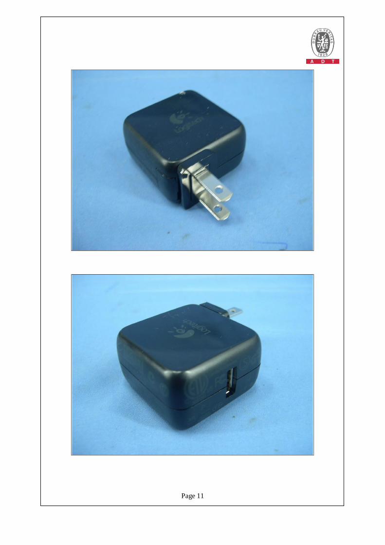
2. The EUT must be supplied with a power adapter as following table: Logitech Brand Logitech Logitech Model L-L0002
Brand Shunshing Model SDCII5-USB
Input power 100-240V 50/60Hz 180mA Output power 5V 1A
Report No.: FD980710H04A 6 Report Format Version 3.0.0 Reference No.: 981201H02
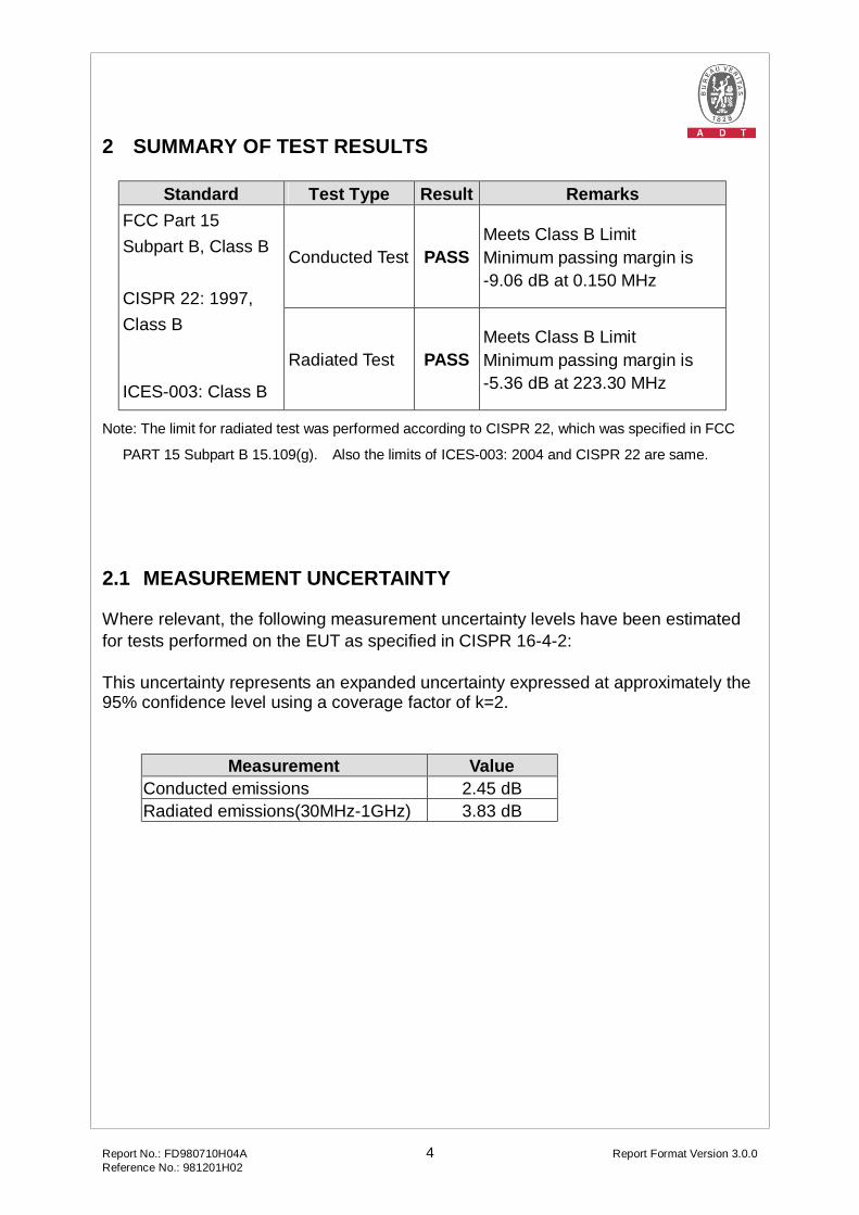
3. The EUT was pre-tested under the following test modes for three different axes placements: Test Mode Description Mode A X-Y plane Mode B X-Z plane Mode C Y-Z plane From the above modes, the worst emission level was found in Mode A. Therefore only the test data of the modes were recorded in this report individually.
4. The EUT was pre-tested under following test modes: Test Mode Description Mode A JEM recharge USB cable Mode B Sinbon recharge USB cable From the above modes, the worst emission level was found in Mode A. Therefore only the test data of the modes were recorded in this report individually.
5. The above EUT information was declared by the manufacturer and for more detailed features description, please refer to the manufacturer's specifications or User's Manual.
3.2 GENERAL DESCRIPTION OF TEST MODE
The EUT was tested with the following modes: Conducted test Test Mode Description Sample Mode 1 Remote + Adapter + JEM recharge cable Sample 1 Mode 2 Remote + PC + JEM recharge cable Sample 1 Mode 3 Remote + PC + JEM recharge cable Sample 2 Mode 4 Remote + PC + JEM recharge cable Sample 3 Radiated test Test Mode Description Sample Mode 1 Remote + Batteries Sample 1 Mode 2 Remote + Adapter + JEM recharge cable Sample 1 Mode 3 Remote + PC + JEM recharge cable Sample 1 Mode 4 Remote + PC + JEM recharge cable Sample 2 Mode 5 Remote + PC + JEM recharge cable Sample 3

Report No.: FD980710H04A 7 Report Format Version 3.0.0 Reference No.: 981201H02
3.3 DESCRIPTION OF SUPPORT UNITS The EUT has been tested as an independent unit together with other necessary accessories or support units. The following support units or accessories were used to form a representative test configuration during the tests.
For Sample 1: Conducted and Radiated test No. Product Brand Model No. Serial No. FCC ID 1 PC DELL DCSM G84QL1S FCC DoC
2 MONITOR DELL E228WFPc CN-OX765G-64180-88P-09ZM
FCC DoC
3 PRINTER EPSON LQ-300+ DCGY017097 FCC DoC 4 MODEM ACEEX 1414 0206026775 IFAXDM1414
5 KEYBOARD DELL SK-8115 MY-0J4635-71619-67V-0114
FCC DoC
6 MOUSE DELL M056UOA FOROOBSN FCC DoC 7 CD Player PHLIPS MCM240/21T NA NA
For Sample 2 & 3: Conducted and Radiated test No. Product Brand Model No. Serial No. FCC ID
PC (For conducted test)
DELL DC01L 8P7WV1S FCC DoC 1
PC(For radiated test)
DELL DCSM G84QL1S FCC DoC
2 MONITOR DELL E228WFPc CN-OX765G-64180-88P-0BTM
FCC DoC
PRINTER (For conducted test)
CANON K10202 FASF84644 FCC DoC 3
PRINTER(For radiated test)
EPSON LQ-300+ DCGY017097 FCC DoC
4 MODEM ACEEX 1414 0206026775 IFAXDM1414
5 KEYBOARD DELL SK-8115 CN-0J4635-71616-53A-0CH2
FCC DoC
6 MOUSE DELL M056UOA FOROOSWW FCC DoC
Report No.: FD980710H04A 8 Report Format Version 3.0.0 Reference No.: 981201H02
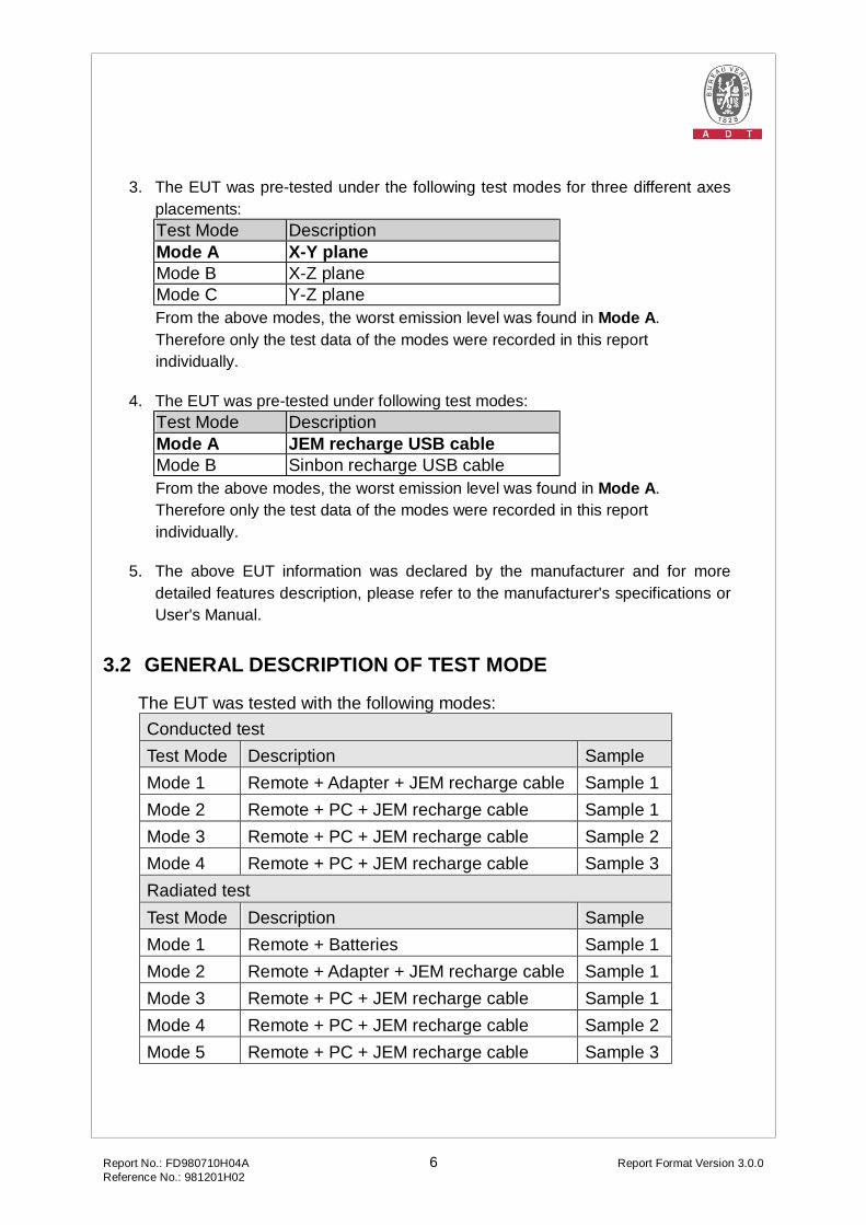
For Sample 1: Conducted and Radiated test No. Signal cable description 1 0.8m foil unshielded wire, USB Connector, with two cores. 2 1.8m braid shielded wire, VGA & DVI connector, with two cores.
3 1.8 m braid shielded wire, terminated with DB25 and centronics connector via metallic frame, w/o core
4 1 m braid shielded wire, terminated with DB25 and DB9 connector via metallic frame, w/o core. 5 1.9m foil shielded wire, USB Connector, w/o core. 6 1.8m foil shielded wire, USB Connector, w/o core. 7 NA
For Sample 2 & 3: Conducted and Radiated test No. Signal cable description 1 0.8m foil unshielded wire, USB Connector, with two cores. 2 1.8m braid shielded wire, VGA & DVI connector, with two cores.
3 1.8 m braid shielded wire, terminated with DB25 and centronics connector via metallic frame, w/o core
4 1 m braid shielded wire, terminated with DB25 and DB9 connector via metallic frame, w/o core. 5 1.9m foil shielded wire, USB Connector, w/o core. 6 1.8m foil shielded wire, USB Connector, w/o core.
Note: The power cords of the above support units were unshielded (1.8m).
Report No.: FD980710H04A 9 Report Format Version 3.0.0 Reference No.: 981201H02
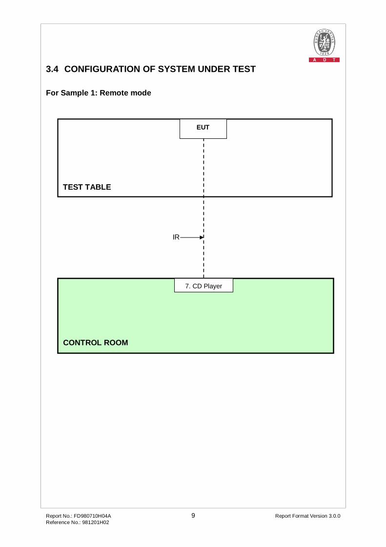
3.4 CONFIGURATION OF SYSTEM UNDER TEST For Sample 1: Remote mode
TEST TABLE
CONTROL ROOM
IR
7. CD Player
EUT
Report No.: FD980710H04A 10 Report Format Version 3.0.0 Reference No.: 981201H02
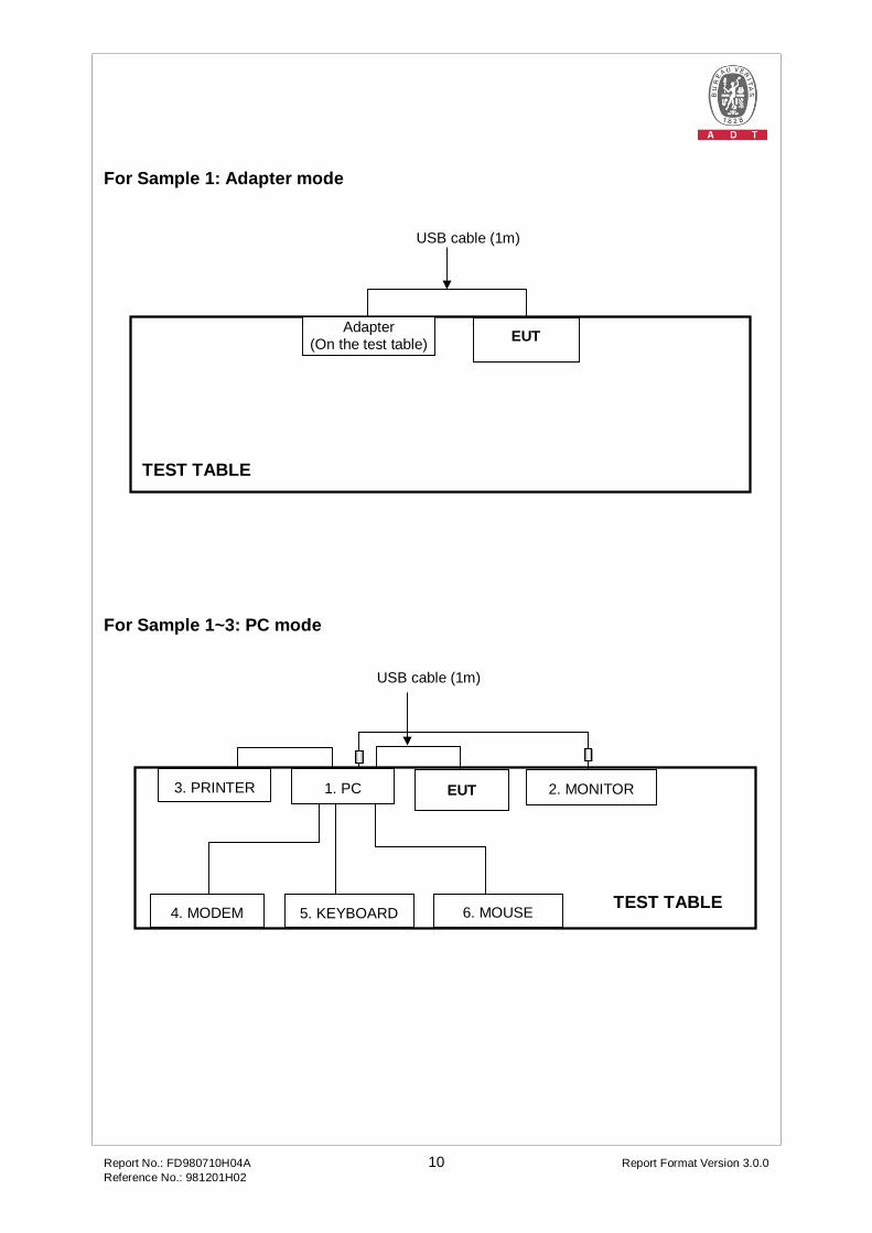
For Sample 1: Adapter mode
For Sample 1~3: PC mode
TEST TABLE
3. PRINTER
4. MODEM 5. KEYBOARD
2. MONITOR EUT
USB cable (1m)
1. PC
6. MOUSE
TEST TABLE
Adapter (On the test table) EUT
USB cable (1m)
Report No.: FD980710H04A 11 Report Format Version 3.0.0 Reference No.: 981201H02
4 EMISSION TEST
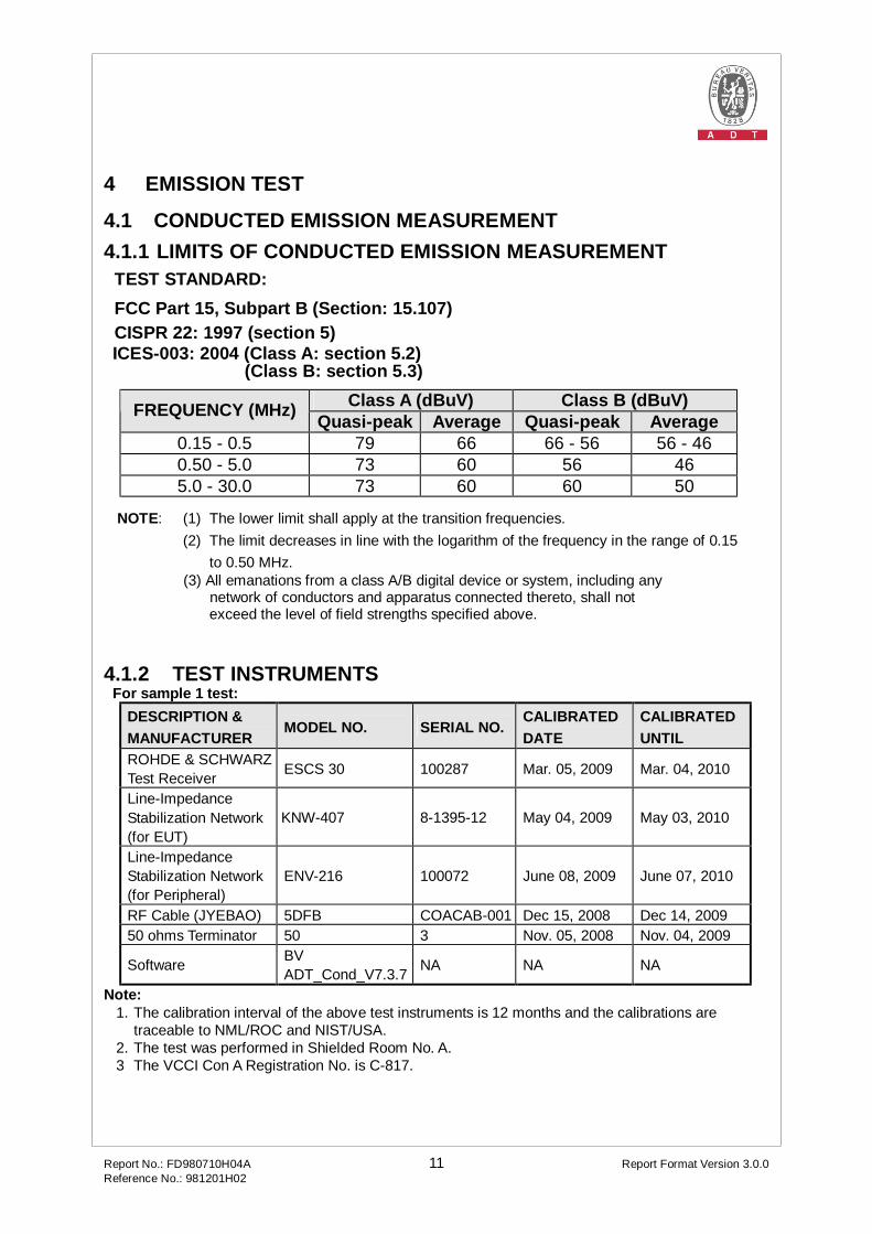
4.1 CONDUCTED EMISSION MEASUREMENT 4.1.1 LIMITS OF CONDUCTED EMISSION MEASUREMENT
TEST STANDARD: FCC Part 15, Subpart B (Section: 15.107) CISPR 22: 1997 (section 5)
ICES-003: 2004 (Class A: section 5.2) (Class B: section 5.3)
Class A (dBuV) Class B (dBuV) FREQUENCY (MHz) Quasi-peak Average Quasi-peak Average 0.15 - 0.5 79 66 66 - 56 56 - 46 0.50 - 5.0 73 60 56 46 5.0 - 30.0 73 60 60 50
NOTE: (1) The lower limit shall apply at the transition frequencies. (2) The limit decreases in line with the logarithm of the frequency in the range of 0.15
to 0.50 MHz. (3) All emanations from a class A/B digital device or system, including any
network of conductors and apparatus connected thereto, shall not exceed the level of field strengths specified above.
4.1.2 TEST INSTRUMENTS For sample 1 test:
DESCRIPTION & MANUFACTURER
MODEL NO. SERIAL NO. CALIBRATED DATE
CALIBRATED UNTIL
ROHDE & SCHWARZ Test Receiver ESCS 30 100287 Mar. 05, 2009 Mar. 04, 2010
Line-Impedance Stabilization Network (for EUT)
KNW-407 8-1395-12 May 04, 2009 May 03, 2010
Line-Impedance Stabilization Network (for Peripheral)
ENV-216 100072 June 08, 2009 June 07, 2010
RF Cable (JYEBAO) 5DFB COACAB-001 Dec 15, 2008 Dec 14, 2009 50 ohms Terminator 50 3 Nov. 05, 2008 Nov. 04, 2009
Software BV ADT_Cond_V7.3.7 NA NA NA
Note: 1. The calibration interval of the above test instruments is 12 months and the calibrations are
traceable to NML/ROC and NIST/USA. 2. The test was performed in Shielded Room No. A. 3 The VCCI Con A Registration No. is C-817.
Report No.: FD980710H04A 12 Report Format Version 3.0.0 Reference No.: 981201H02
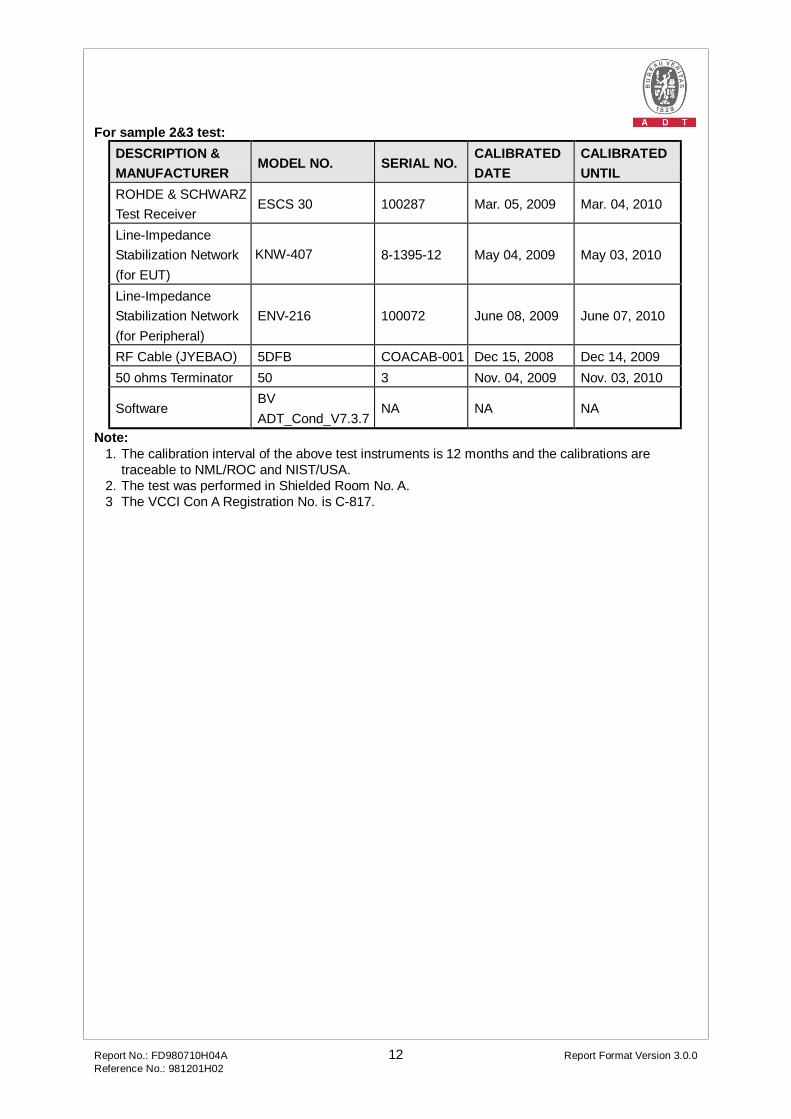
For sample 2&3 test: DESCRIPTION & MANUFACTURER
MODEL NO. SERIAL NO. CALIBRATED DATE
CALIBRATED UNTIL
ROHDE & SCHWARZ Test Receiver
ESCS 30 100287 Mar. 05, 2009 Mar. 04, 2010
Line-Impedance Stabilization Network (for EUT)
KNW-407 8-1395-12 May 04, 2009 May 03, 2010
Line-Impedance Stabilization Network (for Peripheral)
ENV-216 100072 June 08, 2009 June 07, 2010
RF Cable (JYEBAO) 5DFB COACAB-001 Dec 15, 2008 Dec 14, 2009 50 ohms Terminator 50 3 Nov. 04, 2009 Nov. 03, 2010
Software BV ADT_Cond_V7.3.7
NA NA NA
Note: 1. The calibration interval of the above test instruments is 12 months and the calibrations are
traceable to NML/ROC and NIST/USA. 2. The test was performed in Shielded Room No. A. 3 The VCCI Con A Registration No. is C-817.
Report No.: FD980710H04A 13 Report Format Version 3.0.0 Reference No.: 981201H02
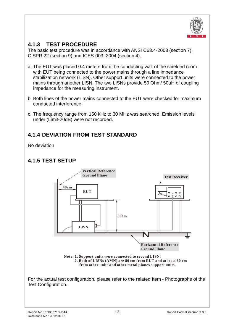
4.1.3 TEST PROCEDURE The basic test procedure was in accordance with ANSI C63.4-2003 (section 7), CISPR 22 (section 9) and ICES-003: 2004 (section 4). a. The EUT was placed 0.4 meters from the conducting wall of the shielded room
with EUT being connected to the power mains through a line impedance stabilization network (LISN). Other support units were connected to the power mains through another LISN. The two LISNs provide 50 Ohm/ 50uH of coupling impedance for the measuring instrument.
b. Both lines of the power mains connected to the EUT were checked for maximum conducted interference.
c. The frequency range from 150 kHz to 30 MHz was searched. Emission levels under (Limit-20dB) were not recorded.
4.1.4 DEVIATION FROM TEST STANDARD No deviation
4.1.5 TEST SETUP
Note: 1. Support units were connected to second LISN. 2. Both of LISNs (AMN) are 80 cm from EUT and at least 80 cm from other units and other metal planes support units.
Vertical ReferenceGround Plane
40cm
80cm
Test Receiver
Horizontal ReferenceGround Plane
EUT
LISN
For the actual test configuration, please refer to the related Item - Photographs of the Test Configuration.
Report No.: FD980710H04A 14 Report Format Version 3.0.0 Reference No.: 981201H02
4.1.6 EUT OPERATING CONDITIONS
For test mode 1: 1. Set the EUT under charger condition.
For test mode 2~4: 1. Turn on the power of all equipment. 2. PC runs the test program "Logitech runclient.bat" to enable EUT under
transmission/receiving condition continuously via one USB cable
Report No.: FD980710H04A 15 Report Format Version 3.0.0 Reference No.: 981201H02
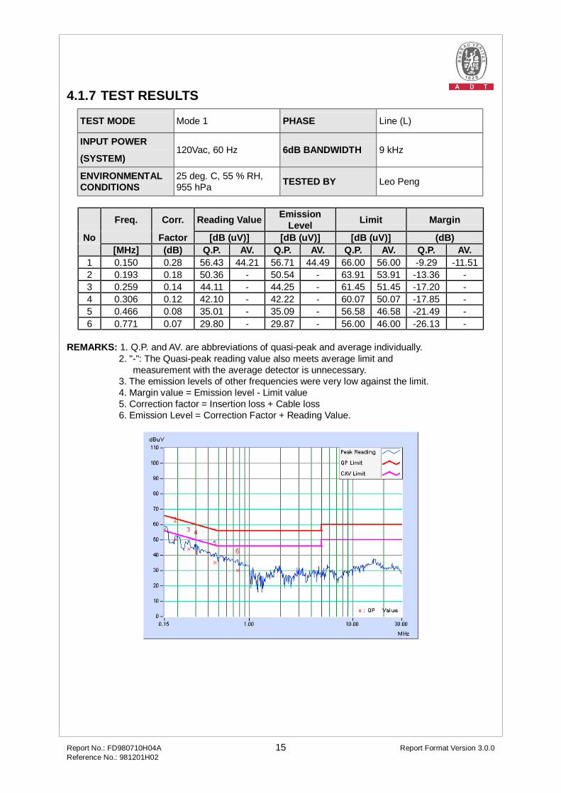
4.1.7 TEST RESULTS
TEST MODE Mode 1 PHASE Line (L)
INPUT POWER
(SYSTEM) 120Vac, 60 Hz 6dB BANDWIDTH 9 kHz
ENVIRONMENTAL CONDITIONS
25 deg. C, 55 % RH, 955 hPa TESTED BY Leo Peng
Freq. Corr. Reading Value Emission Level Limit Margin
No Factor [dB (uV)] [dB (uV)] [dB (uV)] (dB) [MHz] (dB) Q.P. AV. Q.P. AV. Q.P. AV. Q.P. AV. 1 0.150 0.28 56.43 44.21 56.71 44.49 66.00 56.00 -9.29 -11.51 2 0.193 0.18 50.36 - 50.54 - 63.91 53.91 -13.36 - 3 0.259 0.14 44.11 - 44.25 - 61.45 51.45 -17.20 - 4 0.306 0.12 42.10 - 42.22 - 60.07 50.07 -17.85 - 5 0.466 0.08 35.01 - 35.09 - 56.58 46.58 -21.49 - 6 0.771 0.07 29.80 - 29.87 - 56.00 46.00 -26.13 -
REMARKS: 1. Q.P. and AV. are abbreviations of quasi-peak and average individually. 2. "-": The Quasi-peak reading value also meets average limit and measurement with the average detector is unnecessary. 3. The emission levels of other frequencies were very low against the limit. 4. Margin value = Emission level - Limit value 5. Correction factor = Insertion loss + Cable loss 6. Emission Level = Correction Factor + Reading Value.

Report No.: FD980710H04A 16 Report Format Version 3.0.0 Reference No.: 981201H02
TEST MODE Mode 1 PHASE Neutral (N)
INPUT POWER
(SYSTEM) 120Vac, 60 Hz 6dB BANDWIDTH 9 kHz
ENVIRONMENTAL CONDITIONS
25 deg. C, 55 % RH, 955 hPa TESTED BY Leo Peng
Freq. Corr. Reading Value Emission Level Limit Margin
No Factor [dB (uV)] [dB (uV)] [dB (uV)] (dB) [MHz] (dB) Q.P. AV. Q.P. AV. Q.P. AV. Q.P. AV. 1 0.150 0.28 56.66 44.41 56.94 44.69 66.00 56.00 -9.06 -11.31 2 0.197 0.19 50.50 - 50.69 - 63.74 53.74 -13.06 - 3 0.302 0.13 42.12 - 42.25 - 60.18 50.18 -17.92 - 4 0.365 0.11 38.35 - 38.46 - 58.62 48.62 -20.16 - 5 0.685 0.09 32.63 - 32.72 - 56.00 46.00 -23.28 - 6 1.871 0.10 33.42 - 33.52 - 56.00 46.00 -22.48 -
REMARKS: 1. Q.P. and AV. are abbreviations of quasi-peak and average individually. 2. "-": The Quasi-peak reading value also meets average limit and measurement with the average detector is unnecessary. 3. The emission levels of other frequencies were very low against the limit. 4. Margin value = Emission level - Limit value 5. Correction factor = Insertion loss + Cable loss 6. Emission Level = Correction Factor + Reading Value.
Report No.: FD980710H04A 17 Report Format Version 3.0.0 Reference No.: 981201H02
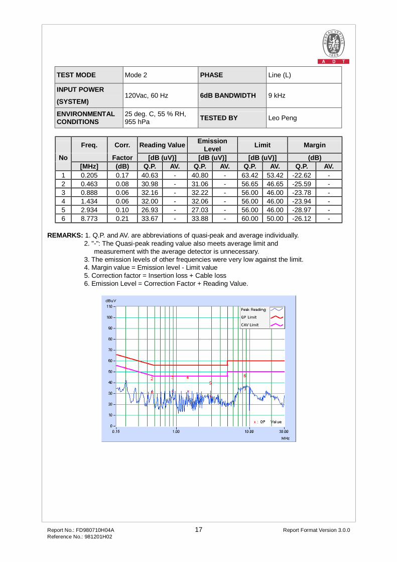
TEST MODE Mode 2 PHASE Line (L)
INPUT POWER
(SYSTEM) 120Vac, 60 Hz 6dB BANDWIDTH 9 kHz
ENVIRONMENTAL CONDITIONS
25 deg. C, 55 % RH, 955 hPa TESTED BY Leo Peng
Freq. Corr. Reading Value Emission Level Limit Margin
No Factor [dB (uV)] [dB (uV)] [dB (uV)] (dB) [MHz] (dB) Q.P. AV. Q.P. AV. Q.P. AV. Q.P. AV. 1 0.205 0.17 40.63 - 40.80 - 63.42 53.42 -22.62 - 2 0.463 0.08 30.98 - 31.06 - 56.65 46.65 -25.59 - 3 0.888 0.06 32.16 - 32.22 - 56.00 46.00 -23.78 - 4 1.434 0.06 32.00 - 32.06 - 56.00 46.00 -23.94 - 5 2.934 0.10 26.93 - 27.03 - 56.00 46.00 -28.97 - 6 8.773 0.21 33.67 - 33.88 - 60.00 50.00 -26.12 -
REMARKS: 1. Q.P. and AV. are abbreviations of quasi-peak and average individually. 2. "-": The Quasi-peak reading value also meets average limit and measurement with the average detector is unnecessary. 3. The emission levels of other frequencies were very low against the limit. 4. Margin value = Emission level - Limit value 5. Correction factor = Insertion loss + Cable loss 6. Emission Level = Correction Factor + Reading Value.

Report No.: FD980710H04A 18 Report Format Version 3.0.0 Reference No.: 981201H02
TEST MODE Mode 2 PHASE Neutral (N)
INPUT POWER
(SYSTEM) 120Vac, 60 Hz 6dB BANDWIDTH 9 kHz
ENVIRONMENTAL CONDITIONS
25 deg. C, 55 % RH, 955 hPa TESTED BY Leo Peng
Freq. Corr. Reading Value Emission Level Limit Margin
No Factor [dB (uV)] [dB (uV)] [dB (uV)] (dB) [MHz] (dB) Q.P. AV. Q.P. AV. Q.P. AV. Q.P. AV. 1 0.205 0.18 46.36 - 46.54 - 63.42 53.42 -16.88 - 2 0.271 0.15 36.95 - 37.10 - 61.08 51.08 -23.99 - 3 0.341 0.12 36.27 - 36.39 - 59.17 49.17 -22.78 - 4 0.463 0.09 32.30 - 32.39 - 56.65 46.65 -24.26 - 5 0.955 0.08 24.83 - 24.91 - 56.00 46.00 -31.09 - 6 8.875 0.24 29.06 - 29.30 - 60.00 50.00 -30.70 -
REMARKS: 1. Q.P. and AV. are abbreviations of quasi-peak and average individually. 2. "-": The Quasi-peak reading value also meets average limit and measurement with the average detector is unnecessary. 3. The emission levels of other frequencies were very low against the limit. 4. Margin value = Emission level - Limit value 5. Correction factor = Insertion loss + Cable loss 6. Emission Level = Correction Factor + Reading Value.

Report No.: FD980710H04A 19 Report Format Version 3.0.0 Reference No.: 981201H02
TEST MODE Mode 3 PHASE Line (L)
INPUT POWER
(SYSTEM) 120Vac, 60 Hz 6dB BANDWIDTH 9 kHz
ENVIRONMENTAL CONDITIONS
25 deg. C, 60 % RH, 1014 hPa TESTED BY Eagle Chen
Freq. Corr. Reading Value Emission Level Limit Margin
No Factor [dB (uV)] [dB (uV)] [dB (uV)] (dB) [MHz] (dB) Q.P. AV. Q.P. AV. Q.P. AV. Q.P. AV. 1 0.173 0.23 31.13 - 31.36 - 64.79 54.79 -33.44 - 2 0.556 0.07 31.13 - 31.20 - 56.00 46.00 -24.80 - 3 0.974 0.06 32.92 - 32.98 - 56.00 46.00 -23.02 - 4 11.063 0.26 36.44 - 36.70 - 60.00 50.00 -23.30 - 5 16.555 0.40 46.59 - 46.99 - 60.00 50.00 -13.01 - 6 24.004 0.55 29.73 - 30.28 - 60.00 50.00 -29.72 -
REMARKS: 1. Q.P. and AV. are abbreviations of quasi-peak and average individually. 2. "-": The Quasi-peak reading value also meets average limit and measurement with the average detector is unnecessary. 3. The emission levels of other frequencies were very low against the limit. 4. Margin value = Emission level - Limit value 5. Correction factor = Insertion loss + Cable loss 6. Emission Level = Correction Factor + Reading Value.

Report No.: FD980710H04A 20 Report Format Version 3.0.0 Reference No.: 981201H02
TEST MODE Mode 3 PHASE Neutral (N)
INPUT POWER
(SYSTEM) 120Vac, 60 Hz 6dB BANDWIDTH 9 kHz
ENVIRONMENTAL CONDITIONS
25 deg. C, 60 % RH, 1014 hPa TESTED BY Eagle Chen
Freq. Corr. Reading Value Emission Level Limit Margin
No Factor [dB (uV)] [dB (uV)] [dB (uV)] (dB) [MHz] (dB) Q.P. AV. Q.P. AV. Q.P. AV. Q.P. AV. 1 0.150 0.28 32.91 - 33.19 - 66.00 56.00 -32.81 - 2 0.173 0.23 31.05 - 31.28 - 64.79 54.79 -33.51 - 3 0.974 0.08 29.97 - 30.05 - 56.00 46.00 -25.95 - 4 4.313 0.17 29.60 - 29.77 - 56.00 46.00 -26.23 - 5 11.617 0.30 32.89 - 33.19 - 60.00 50.00 -26.81 - 6 16.215 0.42 44.18 - 44.60 - 60.00 50.00 -15.40 -
REMARKS: 1. Q.P. and AV. are abbreviations of quasi-peak and average individually. 2. "-": The Quasi-peak reading value also meets average limit and measurement with the average detector is unnecessary. 3. The emission levels of other frequencies were very low against the limit. 4. Margin value = Emission level - Limit value 5. Correction factor = Insertion loss + Cable loss 6. Emission Level = Correction Factor + Reading Value.

Report No.: FD980710H04A 21 Report Format Version 3.0.0 Reference No.: 981201H02
TEST MODE Mode 4 PHASE Line (L)
INPUT POWER
(SYSTEM) 120Vac, 60 Hz 6dB BANDWIDTH 9 kHz
ENVIRONMENTAL CONDITIONS
25 deg. C, 60 % RH, 1014 hPa TESTED BY Eagle Chen
Freq. Corr. Reading Value Emission Level Limit Margin
No Factor [dB (uV)] [dB (uV)] [dB (uV)] (dB) [MHz] (dB) Q.P. AV. Q.P. AV. Q.P. AV. Q.P. AV. 1 0.173 0.23 30.69 - 30.92 - 64.79 54.79 -33.88 - 2 0.349 0.10 30.28 - 30.38 - 58.98 48.98 -28.60 - 3 0.556 0.07 30.97 - 31.04 - 56.00 46.00 -24.96 - 4 0.974 0.06 32.08 - 32.14 - 56.00 46.00 -23.86 - 5 1.047 0.06 29.56 - 29.62 - 56.00 46.00 -26.38 - 6 15.934 0.38 46.44 - 46.82 - 60.00 50.00 -13.18 -
REMARKS: 1. Q.P. and AV. are abbreviations of quasi-peak and average individually. 2. "-": The Quasi-peak reading value also meets average limit and measurement with the average detector is unnecessary. 3. The emission levels of other frequencies were very low against the limit. 4. Margin value = Emission level - Limit value 5. Correction factor = Insertion loss + Cable loss 6. Emission Level = Correction Factor + Reading Value.

Report No.: FD980710H04A 22 Report Format Version 3.0.0 Reference No.: 981201H02
TEST MODE Mode 4 PHASE Neutral (N)
INPUT POWER
(SYSTEM) 120Vac, 60 Hz 6dB BANDWIDTH 9 kHz
ENVIRONMENTAL CONDITIONS
25 deg. C, 60 % RH, 1014 hPa TESTED BY Eagle Chen
Freq. Corr. Reading Value Emission Level Limit Margin
No Factor [dB (uV)] [dB (uV)] [dB (uV)] (dB) [MHz] (dB) Q.P. AV. Q.P. AV. Q.P. AV. Q.P. AV. 1 0.173 0.23 30.91 - 31.14 - 64.79 54.79 -33.65 - 2 0.209 0.18 32.46 - 32.64 - 63.26 53.26 -30.63 - 3 0.279 0.14 29.61 - 29.75 - 60.85 50.85 -31.09 - 4 1.047 0.08 34.35 - 34.43 - 56.00 46.00 -21.57 - 5 4.035 0.16 29.29 - 29.45 - 56.00 46.00 -26.55 - 6 16.770 0.43 44.99 - 45.42 - 60.00 50.00 -14.58 -
REMARKS: 1. Q.P. and AV. are abbreviations of quasi-peak and average individually. 2. "-": The Quasi-peak reading value also meets average limit and measurement with the average detector is unnecessary. 3. The emission levels of other frequencies were very low against the limit. 4. Margin value = Emission level - Limit value 5. Correction factor = Insertion loss + Cable loss 6. Emission Level = Correction Factor + Reading Value.
Report No.: FD980710H04A 23 Report Format Version 3.0.0 Reference No.: 981201H02
4.2 RADIATED EMISSION MEASUREMENT
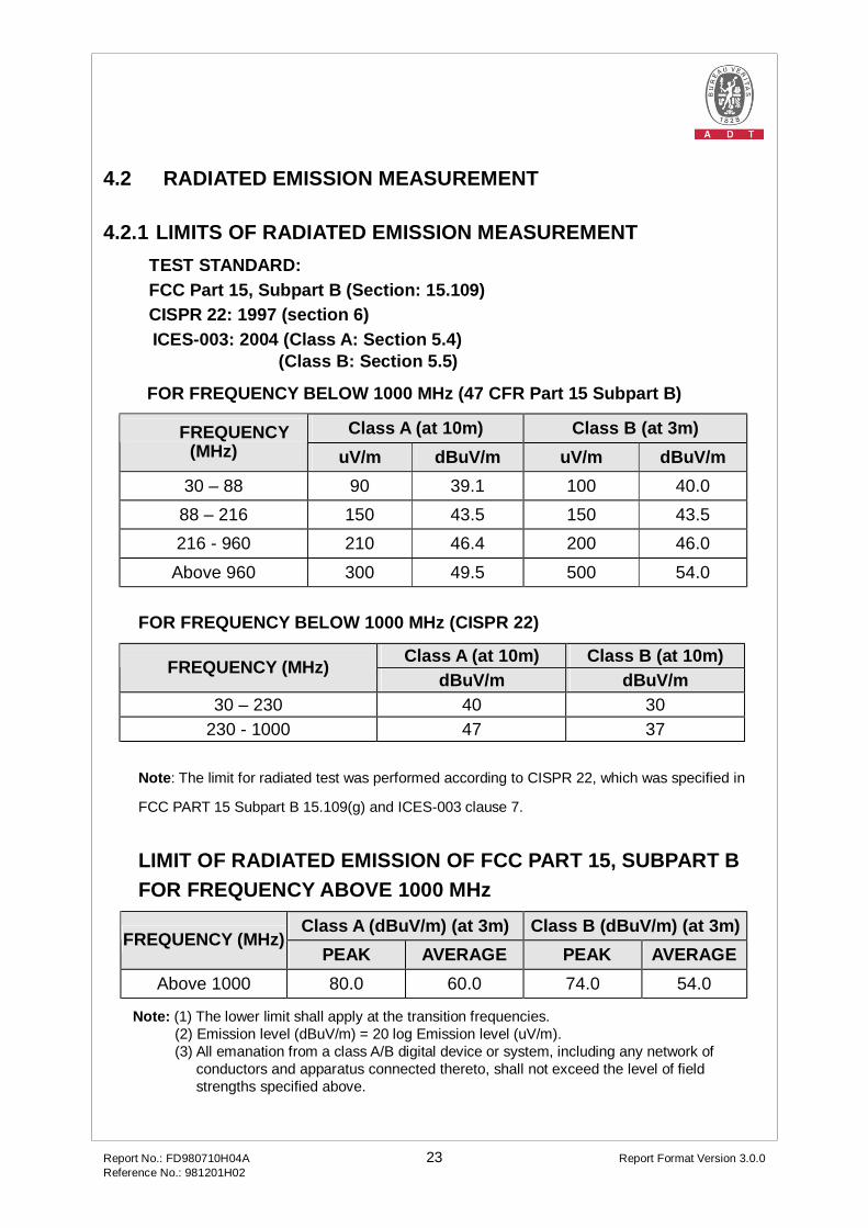
4.2.1 LIMITS OF RADIATED EMISSION MEASUREMENT TEST STANDARD: FCC Part 15, Subpart B (Section: 15.109)
CISPR 22: 1997 (section 6) ICES-003: 2004 (Class A: Section 5.4)
(Class B: Section 5.5)
FOR FREQUENCY BELOW 1000 MHz (47 CFR Part 15 Subpart B)
Class A (at 10m) Class B (at 3m) FREQUENCY (MHz) uV/m dBuV/m uV/m dBuV/m
30 – 88 90 39.1 100 40.0 88 – 216 150 43.5 150 43.5 216 - 960 210 46.4 200 46.0
Above 960 300 49.5 500 54.0
FOR FREQUENCY BELOW 1000 MHz (CISPR 22)
Class A (at 10m) Class B (at 10m) FREQUENCY (MHz) dBuV/m dBuV/m
30 – 230 40 30 230 - 1000 47 37
Note: The limit for radiated test was performed according to CISPR 22, which was specified in
FCC PART 15 Subpart B 15.109(g) and ICES-003 clause 7.
LIMIT OF RADIATED EMISSION OF FCC PART 15, SUBPART B FOR FREQUENCY ABOVE 1000 MHz
Class A (dBuV/m) (at 3m) Class B (dBuV/m) (at 3m) FREQUENCY (MHz)
PEAK AVERAGE PEAK AVERAGE Above 1000 80.0 60.0 74.0 54.0
Note: (1) The lower limit shall apply at the transition frequencies. (2) Emission level (dBuV/m) = 20 log Emission level (uV/m). (3) All emanation from a class A/B digital device or system, including any network of
conductors and apparatus connected thereto, shall not exceed the level of field strengths specified above.
Report No.: FD980710H04A 24 Report Format Version 3.0.0 Reference No.: 981201H02
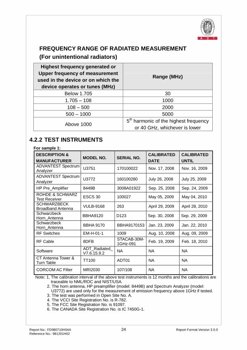
FREQUENCY RANGE OF RADIATED MEASUREMENT (For unintentional radiators) Highest frequency generated or
Upper frequency of measurement used in the device or on which the
device operates or tunes (MHz)
Range (MHz)
Below 1.705 30 1.705 – 108 1000 108 – 500 2000
500 – 1000 5000
Above 1000 5th harmonic of the highest frequency or 40 GHz, whichever is lower
4.2.2 TEST INSTRUMENTS
For sample 1: DESCRIPTION & MANUFACTURER
MODEL NO. SERIAL NO. CALIBRATED DATE
CALIBRATED UNTIL
ADVANTEST Spectrum Analyzer U3751 170100022 Nov. 17, 2008 Nov. 16, 2009
ADVANTEST Spectrum Analyzer U3772 160100280 July 26, 2008 July 25, 2009
HP Pre_Amplifier 8449B 3008A01922 Sep. 25, 2008 Sep. 24, 2009 ROHDE & SCHWARZ Test Receiver ESCS 30 100027 May 05, 2009 May 04, 2010
SCHWARZBECK Broadband Antenna VULB-9168 263 April 29, 2009 April 28, 2010
Schwarzbeck Horn_Antenna BBHA9120 D123 Sep. 30, 2008 Sep. 29, 2009
Schwarzbeck Horn_Antenna BBHA 9170 BBHA9170153 Jan. 23, 2009 Jan. 22, 2010
RF Switches EM-H-01-1 1009 Aug. 10, 2008 Aug. 09, 2009
RF Cable 8DFB STACAB-30M-1GHz-091 Feb. 19, 2009 Feb. 18, 2010
Software ADT_Radiated_V7.6.15.9.2 NA NA NA
CT Antenna Tower & Turn Table TT100 ADT01 NA NA
CORCOM AC Filter MRI2030 107/108 NA NA
Note: 1. The calibration interval of the above test instruments is 12 months and the calibrations are traceable to NML/ROC and NIST/USA.
2. The horn antenna, HP preamplifier (model: 8449B) and Spectrum Analyzer (model: U3772) are used only for the measurement of emission frequency above 1GHz if tested.
3. The test was performed in Open Site No. A. 4. The VCCI Site Registration No. is R-782. 5. The FCC Site Registration No. is 91097. 6. The CANADA Site Registration No. is IC 7450G-1.
Report No.: FD980710H04A 25 Report Format Version 3.0.0 Reference No.: 981201H02
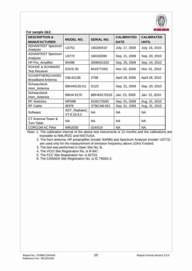
For sample 2&3: DESCRIPTION & MANUFACTURER
MODEL NO. SERIAL NO. CALIBRATED DATE
CALIBRATED UNTIL
ADVANTEST Spectrum Analyzer U3751 160200410 July. 17, 2009 July. 16, 2010
ADVANTEST Spectrum Analyzer U3772 160100280 Sep. 21, 2009 Sep. 20, 2010
HP Pre_Amplifier 8449B 3008A01922 Sep. 25, 2009 Sep. 24, 2010 ROHDE & SCHWARZ Test Receiver
ESVS 30 841977/002 Nov. 02, 2009 Nov. 01, 2010
SCHAFFNER(CHASE) Broadband Antenna CBL6112B 2798 April 29, 2009 April 28, 2010
Schwarzbeck Horn_Antenna BBHA9120-D1 D123 Sep. 21, 2009 Sep. 20, 2010
Schwarzbeck Horn_Antenna BBHA 9170 BBHA9170153 Jan. 23, 2009 Jan. 22, 2010
RF Switches MP59B 6100175593 Sep. 01, 2009 Aug. 31, 2010 RF Cable 8DFB STBCAB-001 Sep. 01, 2009 Aug. 31, 2010
Software ADT_Radiated_V7.6.15.9.2 NA NA NA
CT Antenna Tower & Turn Table NA NA NA NA
CORCOM AC Filter MRI2030 024/019 NA NA Note: 1. The calibration interval of the above test instruments is 12 months and the calibrations are
traceable to NML/ROC and NIST/USA. 2. The horn antenna, HP preamplifier (model: 8449B) and Spectrum Analyzer (model: U3772)
are used only for the measurement of emission frequency above 1GHz if tested. 3. The test was performed in Open Site No. B. 4. The VCCI Site Registration No. is R-847. 5. The FCC Site Registration No. is 92753. 6. The CANADA Site Registration No. is IC 7450G-2.
Report No.: FD980710H04A 26 Report Format Version 3.0.0 Reference No.: 981201H02
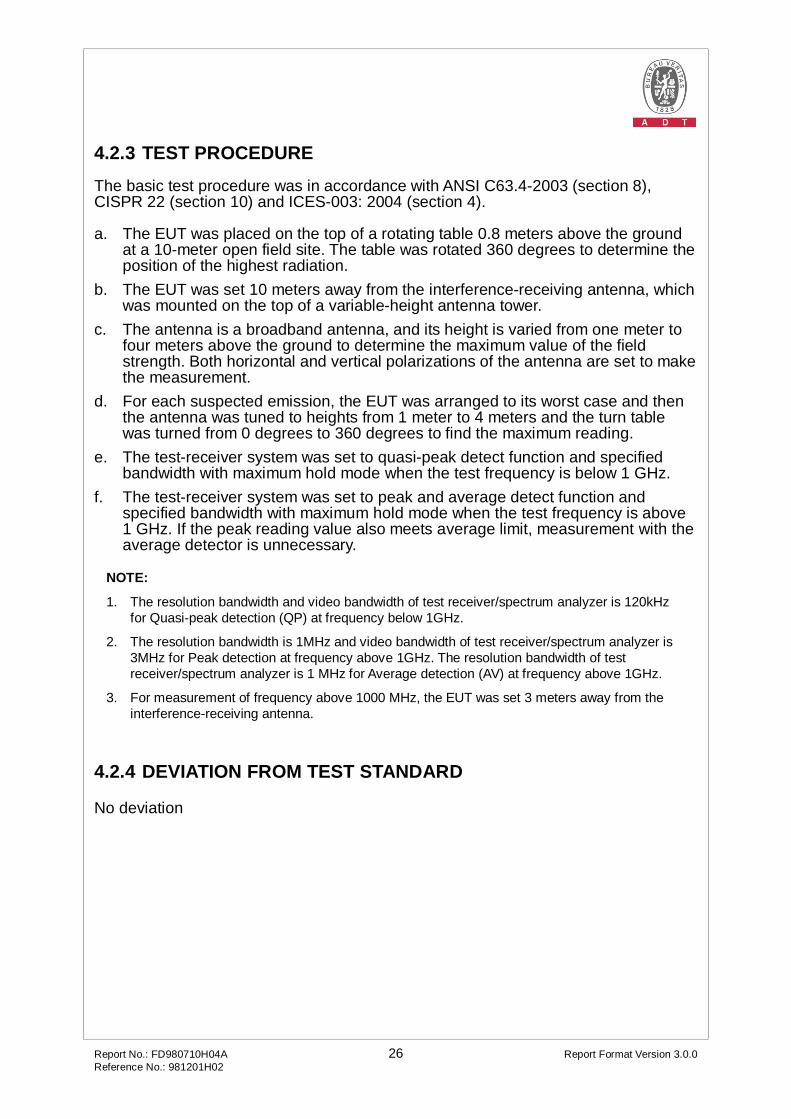
4.2.3 TEST PROCEDURE The basic test procedure was in accordance with ANSI C63.4-2003 (section 8), CISPR 22 (section 10) and ICES-003: 2004 (section 4). a. The EUT was placed on the top of a rotating table 0.8 meters above the ground
at a 10-meter open field site. The table was rotated 360 degrees to determine the position of the highest radiation.
b. The EUT was set 10 meters away from the interference-receiving antenna, which was mounted on the top of a variable-height antenna tower.
c. The antenna is a broadband antenna, and its height is varied from one meter to four meters above the ground to determine the maximum value of the field strength. Both horizontal and vertical polarizations of the antenna are set to make the measurement.
d. For each suspected emission, the EUT was arranged to its worst case and then the antenna was tuned to heights from 1 meter to 4 meters and the turn table was turned from 0 degrees to 360 degrees to find the maximum reading.
e. The test-receiver system was set to quasi-peak detect function and specified bandwidth with maximum hold mode when the test frequency is below 1 GHz.
f. The test-receiver system was set to peak and average detect function and specified bandwidth with maximum hold mode when the test frequency is above 1 GHz. If the peak reading value also meets average limit, measurement with the average detector is unnecessary.
NOTE:
1. The resolution bandwidth and video bandwidth of test receiver/spectrum analyzer is 120kHz for Quasi-peak detection (QP) at frequency below 1GHz.
2. The resolution bandwidth is 1MHz and video bandwidth of test receiver/spectrum analyzer is 3MHz for Peak detection at frequency above 1GHz. The resolution bandwidth of test receiver/spectrum analyzer is 1 MHz for Average detection (AV) at frequency above 1GHz.
3. For measurement of frequency above 1000 MHz, the EUT was set 3 meters away from the interference-receiving antenna.
4.2.4 DEVIATION FROM TEST STANDARD No deviation
Report No.: FD980710H04A 27 Report Format Version 3.0.0 Reference No.: 981201H02
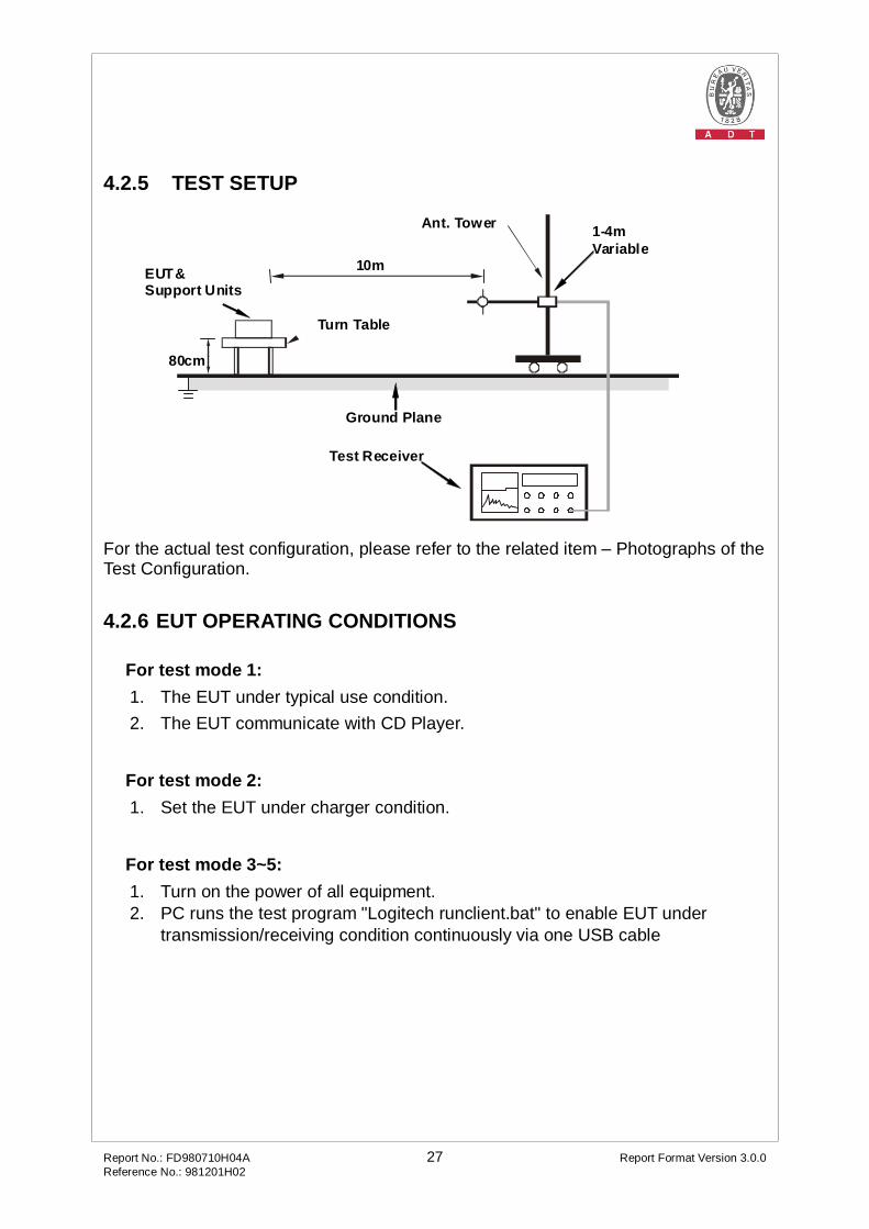
4.2.5 TEST SETUP
10m
Ant. Tower 1-4m Variable
Turn Table
EUT& Support Units
Ground Plane
Test Receiver
80cm
3m-above 1GHz
For the actual test configuration, please refer to the related item – Photographs of the Test Configuration.
4.2.6 EUT OPERATING CONDITIONS For test mode 1: 1. The EUT under typical use condition. 2. The EUT communicate with CD Player. For test mode 2: 1. Set the EUT under charger condition. For test mode 3~5: 1. Turn on the power of all equipment. 2. PC runs the test program "Logitech runclient.bat" to enable EUT under
transmission/receiving condition continuously via one USB cable
Report No.: FD980710H04A 28 Report Format Version 3.0.0 Reference No.: 981201H02
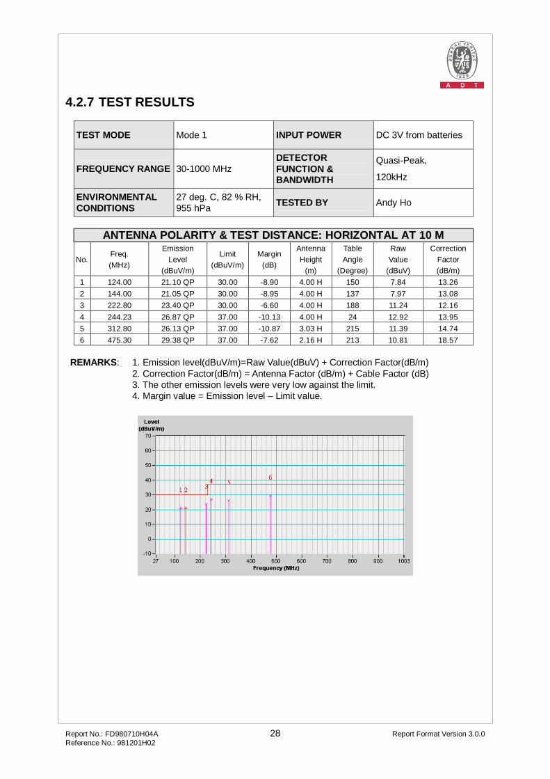
4.2.7 TEST RESULTS
TEST MODE Mode 1 INPUT POWER DC 3V from batteries
FREQUENCY RANGE 30-1000 MHz DETECTOR FUNCTION & BANDWIDTH
Quasi-Peak,
120kHz
ENVIRONMENTAL CONDITIONS
27 deg. C, 82 % RH, 955 hPa TESTED BY Andy Ho
ANTENNA POLARITY & TEST DISTANCE: HORIZONTAL AT 10 M
No. Freq. (MHz)
Emission Level
(dBuV/m)
Limit (dBuV/m)
Margin (dB)
Antenna Height
(m)
Table Angle
(Degree)
Raw Value
(dBuV)
Correction Factor (dB/m)
1 124.00 21.10 QP 30.00 -8.90 4.00 H 150 7.84 13.26 2 144.00 21.05 QP 30.00 -8.95 4.00 H 137 7.97 13.08 3 222.80 23.40 QP 30.00 -6.60 4.00 H 188 11.24 12.16 4 244.23 26.87 QP 37.00 -10.13 4.00 H 24 12.92 13.95 5 312.80 26.13 QP 37.00 -10.87 3.03 H 215 11.39 14.74 6 475.30 29.38 QP 37.00 -7.62 2.16 H 213 10.81 18.57
REMARKS: 1. Emission level(dBuV/m)=Raw Value(dBuV) + Correction Factor(dB/m) 2. Correction Factor(dB/m) = Antenna Factor (dB/m) + Cable Factor (dB) 3. The other emission levels were very low against the limit.
4. Margin value = Emission level – Limit value.
Report No.: FD980710H04A 29 Report Format Version 3.0.0 Reference No.: 981201H02
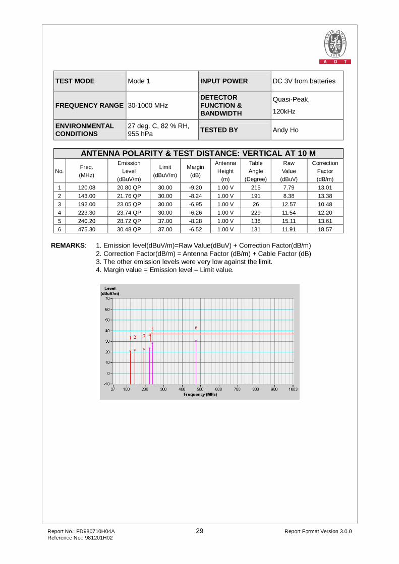
TEST MODE Mode 1 INPUT POWER DC 3V from batteries
FREQUENCY RANGE 30-1000 MHz DETECTOR FUNCTION & BANDWIDTH
Quasi-Peak,
120kHz
ENVIRONMENTAL CONDITIONS
27 deg. C, 82 % RH, 955 hPa TESTED BY Andy Ho
ANTENNA POLARITY & TEST DISTANCE: VERTICAL AT 10 M
No. Freq. (MHz)
Emission Level
(dBuV/m)
Limit (dBuV/m)
Margin (dB)
Antenna Height
(m)
Table Angle
(Degree)
Raw Value
(dBuV)
Correction Factor (dB/m)
1 120.08 20.80 QP 30.00 -9.20 1.00 V 215 7.79 13.01 2 143.00 21.76 QP 30.00 -8.24 1.00 V 191 8.38 13.38 3 192.00 23.05 QP 30.00 -6.95 1.00 V 26 12.57 10.48 4 223.30 23.74 QP 30.00 -6.26 1.00 V 229 11.54 12.20 5 240.20 28.72 QP 37.00 -8.28 1.00 V 138 15.11 13.61 6 475.30 30.48 QP 37.00 -6.52 1.00 V 131 11.91 18.57
REMARKS: 1. Emission level(dBuV/m)=Raw Value(dBuV) + Correction Factor(dB/m) 2. Correction Factor(dB/m) = Antenna Factor (dB/m) + Cable Factor (dB) 3. The other emission levels were very low against the limit.
4. Margin value = Emission level – Limit value.

Report No.: FD980710H04A 30 Report Format Version 3.0.0 Reference No.: 981201H02
TEST MODE Mode 2 INPUT POWER (SYSTEM) 120Vac, 60Hz
FREQUENCY RANGE 30-1000 MHz DETECTOR FUNCTION & BANDWIDTH
Quasi-Peak,
120kHz
ENVIRONMENTAL CONDITIONS
27 deg. C, 82 % RH, 955 hPa TESTED BY Andy Ho
ANTENNA POLARITY & TEST DISTANCE: HORIZONTAL AT 10 M
No. Freq. (MHz)
Emission Level
(dBuV/m)
Limit (dBuV/m)
Margin (dB)
Antenna Height
(m)
Table Angle
(Degree)
Raw Value
(dBuV)
Correction Factor (dB/m)
1 124.00 22.10 QP 30.00 -7.90 4.00 H 250 8.84 13.26 2 144.00 21.95 QP 30.00 -8.05 4.00 H 37 8.87 13.08 3 222.80 24.30 QP 30.00 -5.70 4.00 H 88 12.14 12.16 4 244.23 27.57 QP 37.00 -9.43 4.00 H 224 13.62 13.95 5 312.80 26.83 QP 37.00 -10.17 3.03 H 315 12.09 14.74 6 475.30 29.88 QP 37.00 -7.12 2.16 H 313 11.31 18.57
REMARKS: 1. Emission level(dBuV/m)=Raw Value(dBuV) + Correction Factor(dB/m) 2. Correction Factor(dB/m) = Antenna Factor (dB/m) + Cable Factor (dB) 3. The other emission levels were very low against the limit.
4. Margin value = Emission level – Limit value.

Report No.: FD980710H04A 31 Report Format Version 3.0.0 Reference No.: 981201H02
TEST MODE Mode 2 INPUT POWER (SYSTEM) 120Vac, 60Hz
FREQUENCY RANGE 30-1000 MHz DETECTOR FUNCTION & BANDWIDTH
Quasi-Peak,
120kHz
ENVIRONMENTAL CONDITIONS
27 deg. C, 82 % RH, 955 hPa TESTED BY Andy Ho
ANTENNA POLARITY & TEST DISTANCE: VERTICAL AT 10 M
No. Freq. (MHz)
Emission Level
(dBuV/m)
Limit (dBuV/m)
Margin (dB)
Antenna Height
(m)
Table Angle
(Degree)
Raw Value
(dBuV)
Correction Factor (dB/m)
1 120.08 21.80 QP 30.00 -8.20 1.00 V 115 8.79 13.01 2 143.00 22.46 QP 30.00 -7.54 1.00 V 131 9.08 13.38 3 192.00 22.65 QP 30.00 -7.35 1.00 V 316 12.17 10.48 4 223.30 24.34 QP 30.00 -5.66 1.00 V 29 12.14 12.20 5 240.20 30.02 QP 37.00 -6.98 1.00 V 38 16.41 13.61 6 475.30 30.68 QP 37.00 -6.32 1.00 V 331 12.11 18.57
REMARKS: 1. Emission level(dBuV/m)=Raw Value(dBuV) + Correction Factor(dB/m) 2. Correction Factor(dB/m) = Antenna Factor (dB/m) + Cable Factor (dB) 3. The other emission levels were very low against the limit.
4. Margin value = Emission level – Limit value.
Report No.: FD980710H04A 32 Report Format Version 3.0.0 Reference No.: 981201H02
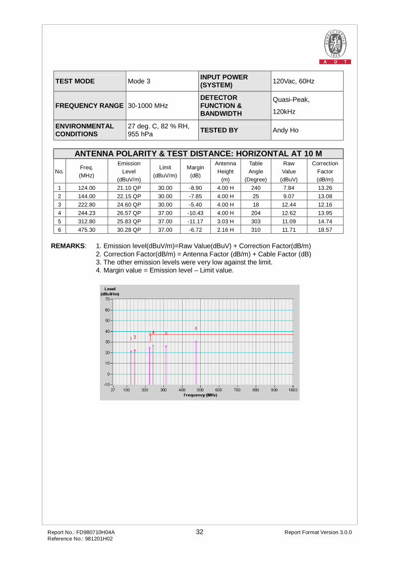
TEST MODE Mode 3 INPUT POWER (SYSTEM) 120Vac, 60Hz
FREQUENCY RANGE 30-1000 MHz DETECTOR FUNCTION & BANDWIDTH
Quasi-Peak,
120kHz
ENVIRONMENTAL CONDITIONS
27 deg. C, 82 % RH, 955 hPa TESTED BY Andy Ho
ANTENNA POLARITY & TEST DISTANCE: HORIZONTAL AT 10 M
No. Freq. (MHz)
Emission Level
(dBuV/m)
Limit (dBuV/m)
Margin (dB)
Antenna Height
(m)
Table Angle
(Degree)
Raw Value
(dBuV)
Correction Factor (dB/m)
1 124.00 21.10 QP 30.00 -8.90 4.00 H 240 7.84 13.26 2 144.00 22.15 QP 30.00 -7.85 4.00 H 25 9.07 13.08 3 222.80 24.60 QP 30.00 -5.40 4.00 H 18 12.44 12.16 4 244.23 26.57 QP 37.00 -10.43 4.00 H 204 12.62 13.95 5 312.80 25.83 QP 37.00 -11.17 3.03 H 303 11.09 14.74 6 475.30 30.28 QP 37.00 -6.72 2.16 H 310 11.71 18.57
REMARKS: 1. Emission level(dBuV/m)=Raw Value(dBuV) + Correction Factor(dB/m) 2. Correction Factor(dB/m) = Antenna Factor (dB/m) + Cable Factor (dB) 3. The other emission levels were very low against the limit.
4. Margin value = Emission level – Limit value.

Report No.: FD980710H04A 33 Report Format Version 3.0.0 Reference No.: 981201H02
TEST MODE Mode 3 INPUT POWER (SYSTEM) 120Vac, 60Hz
FREQUENCY RANGE 30-1000 MHz DETECTOR FUNCTION & BANDWIDTH
Quasi-Peak,
120kHz
ENVIRONMENTAL CONDITIONS
27 deg. C, 82 % RH, 955 hPa TESTED BY Andy Ho
ANTENNA POLARITY & TEST DISTANCE: VERTICAL AT 10 M
No. Freq. (MHz)
Emission Level
(dBuV/m)
Limit (dBuV/m)
Margin (dB)
Antenna Height
(m)
Table Angle
(Degree)
Raw Value
(dBuV)
Correction Factor (dB/m)
1 120.08 20.80 QP 30.00 -9.20 1.00 V 103 7.79 13.01 2 143.00 22.66 QP 30.00 -7.34 1.00 V 29 9.28 13.38 3 192.00 23.15 QP 30.00 -6.85 1.00 V 314 12.67 10.48 4 223.30 24.64 QP 30.00 -5.36 1.00 V 19 12.44 12.20 5 240.20 29.02 QP 37.00 -7.98 1.00 V 18 15.41 13.61 6 475.30 30.28 QP 37.00 -6.72 1.00 V 311 11.71 18.57
REMARKS: 1. Emission level(dBuV/m)=Raw Value(dBuV) + Correction Factor(dB/m) 2. Correction Factor(dB/m) = Antenna Factor (dB/m) + Cable Factor (dB) 3. The other emission levels were very low against the limit.
4. Margin value = Emission level – Limit value.

Report No.: FD980710H04A 34 Report Format Version 3.0.0 Reference No.: 981201H02
TEST MODE Mode 4 INPUT POWER (SYSTEM) 120Vac, 60Hz
FREQUENCY RANGE 30-1000 MHz DETECTOR FUNCTION & BANDWIDTH
Quasi-Peak,
120kHz
ENVIRONMENTAL CONDITIONS
20 deg. C, 73 % RH, 1014 hPa TESTED BY Timmy Hu
ANTENNA POLARITY & TEST DISTANCE: HORIZONTAL AT 10 M
No. Freq. (MHz)
Emission Level
(dBuV/m)
Limit (dBuV/m)
Margin (dB)
Antenna Height
(m)
Table Angle
(Degree)
Raw Value
(dBuV)
Correction Factor (dB/m)
1 120.00 18.20 QP 30.00 -11.80 4.00 H 104 5.62 12.58 2 144.00 20.56 QP 30.00 -9.44 4.00 H 257 8.18 12.38 3 240.01 26.16 QP 37.00 -10.84 3.98 H 343 12.79 13.37 4 480.00 25.22 QP 37.00 -11.78 2.32 H 70 5.32 19.90 5 720.04 26.06 QP 37.00 -10.94 1.28 H 286 3.46 22.60 6 960.07 28.92 QP 37.00 -8.08 1.00 H 30 3.71 25.21
REMARKS: 1. Emission level(dBuV/m)=Raw Value(dBuV) + Correction Factor(dB/m) 2. Correction Factor(dB/m) = Antenna Factor (dB/m) + Cable Factor (dB) 3. The other emission levels were very low against the limit.
4. Margin value = Emission level – Limit value.
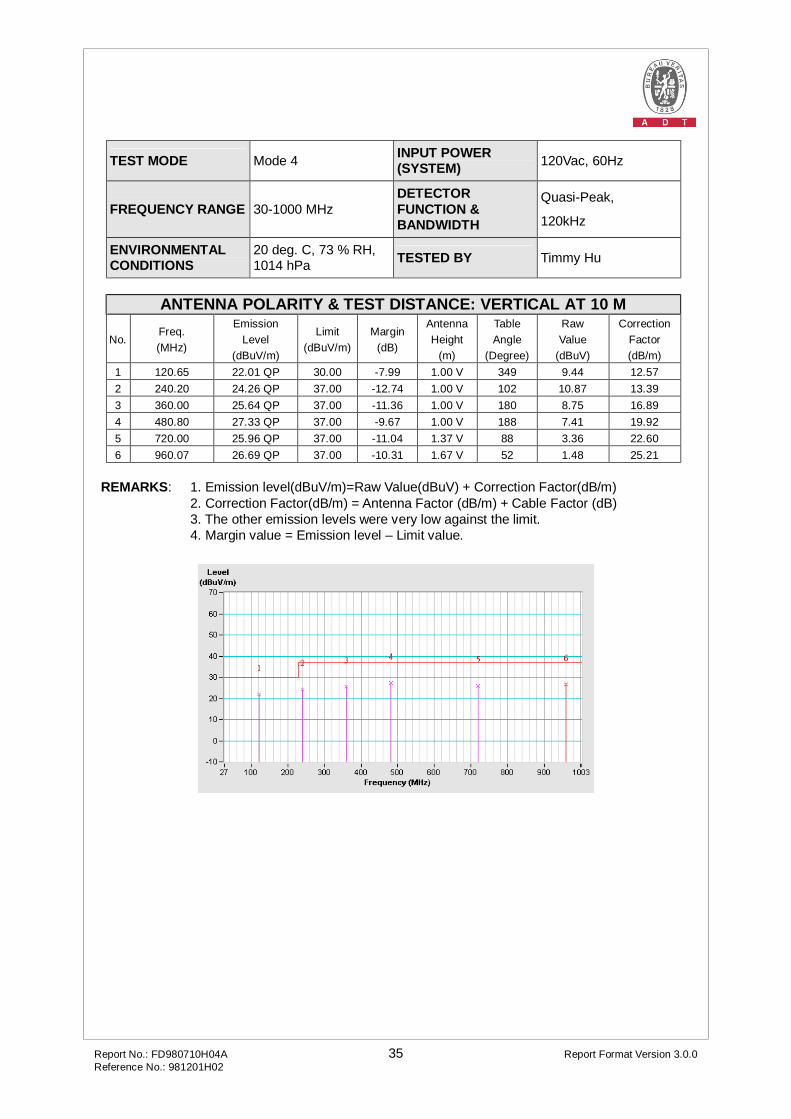
Report No.: FD980710H04A 35 Report Format Version 3.0.0 Reference No.: 981201H02
TEST MODE Mode 4 INPUT POWER (SYSTEM) 120Vac, 60Hz
FREQUENCY RANGE 30-1000 MHz DETECTOR FUNCTION & BANDWIDTH
Quasi-Peak,
120kHz
ENVIRONMENTAL CONDITIONS
20 deg. C, 73 % RH, 1014 hPa TESTED BY Timmy Hu
ANTENNA POLARITY & TEST DISTANCE: VERTICAL AT 10 M
No. Freq. (MHz)
Emission Level
(dBuV/m)
Limit (dBuV/m)
Margin (dB)
Antenna Height
(m)
Table Angle
(Degree)
Raw Value
(dBuV)
Correction Factor (dB/m)
1 120.65 22.01 QP 30.00 -7.99 1.00 V 349 9.44 12.57 2 240.20 24.26 QP 37.00 -12.74 1.00 V 102 10.87 13.39 3 360.00 25.64 QP 37.00 -11.36 1.00 V 180 8.75 16.89 4 480.80 27.33 QP 37.00 -9.67 1.00 V 188 7.41 19.92 5 720.00 25.96 QP 37.00 -11.04 1.37 V 88 3.36 22.60 6 960.07 26.69 QP 37.00 -10.31 1.67 V 52 1.48 25.21
REMARKS: 1. Emission level(dBuV/m)=Raw Value(dBuV) + Correction Factor(dB/m) 2. Correction Factor(dB/m) = Antenna Factor (dB/m) + Cable Factor (dB) 3. The other emission levels were very low against the limit.
4. Margin value = Emission level – Limit value.

Report No.: FD980710H04A 36 Report Format Version 3.0.0 Reference No.: 981201H02
TEST MODE Mode 5 INPUT POWER (SYSTEM) 120Vac, 60Hz
FREQUENCY RANGE 30-1000 MHz DETECTOR FUNCTION & BANDWIDTH
Quasi-Peak,
120kHz
ENVIRONMENTAL CONDITIONS
20 deg. C, 73 % RH, 1014 hPa TESTED BY Timmy Hu
ANTENNA POLARITY & TEST DISTANCE: HORIZONTAL AT 10 M
No. Freq. (MHz)
Emission Level
(dBuV/m)
Limit (dBuV/m)
Margin (dB)
Antenna Height
(m)
Table Angle
(Degree)
Raw Value
(dBuV)
Correction Factor (dB/m)
1 120.03 21.52 QP 30.00 -8.48 4.00 H 48 8.94 12.58 2 144.10 20.62 QP 30.00 -9.38 4.00 H 255 8.24 12.38 3 240.92 24.93 QP 37.00 -12.07 4.00 H 354 11.50 13.43 4 360.00 26.24 QP 37.00 -10.76 3.02 H 30 9.35 16.89 5 480.00 25.02 QP 37.00 -11.98 2.41 H 347 5.12 19.90 6 720.30 25.08 QP 37.00 -11.92 1.29 H 277 2.48 22.60 7 960.07 27.07 QP 37.00 -9.93 1.00 H 154 1.86 25.21
REMARKS: 1. Emission level(dBuV/m)=Raw Value(dBuV) + Correction Factor(dB/m) 2. Correction Factor(dB/m) = Antenna Factor (dB/m) + Cable Factor (dB) 3. The other emission levels were very low against the limit.
4. Margin value = Emission level – Limit value.
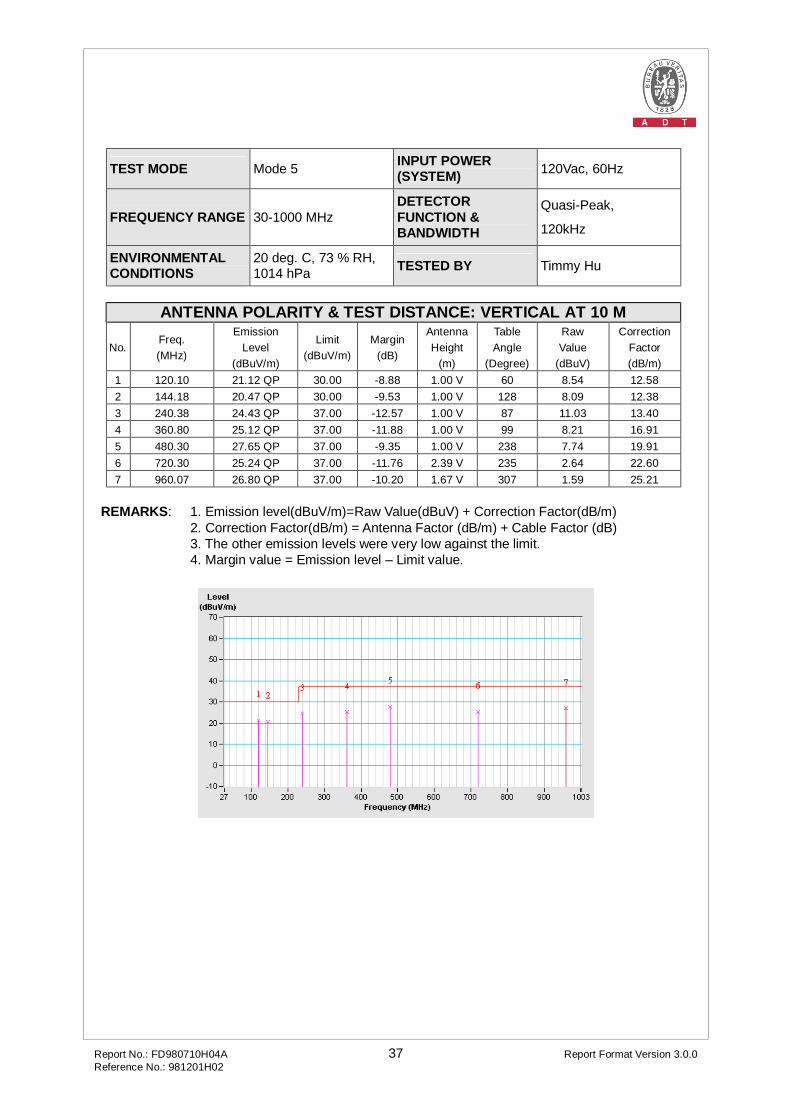
Report No.: FD980710H04A 37 Report Format Version 3.0.0 Reference No.: 981201H02
TEST MODE Mode 5 INPUT POWER (SYSTEM) 120Vac, 60Hz
FREQUENCY RANGE 30-1000 MHz DETECTOR FUNCTION & BANDWIDTH
Quasi-Peak,
120kHz
ENVIRONMENTAL CONDITIONS
20 deg. C, 73 % RH, 1014 hPa TESTED BY Timmy Hu
ANTENNA POLARITY & TEST DISTANCE: VERTICAL AT 10 M
No. Freq. (MHz)
Emission Level
(dBuV/m)
Limit (dBuV/m)
Margin (dB)
Antenna Height
(m)
Table Angle
(Degree)
Raw Value
(dBuV)
Correction Factor (dB/m)
1 120.10 21.12 QP 30.00 -8.88 1.00 V 60 8.54 12.58 2 144.18 20.47 QP 30.00 -9.53 1.00 V 128 8.09 12.38 3 240.38 24.43 QP 37.00 -12.57 1.00 V 87 11.03 13.40 4 360.80 25.12 QP 37.00 -11.88 1.00 V 99 8.21 16.91 5 480.30 27.65 QP 37.00 -9.35 1.00 V 238 7.74 19.91 6 720.30 25.24 QP 37.00 -11.76 2.39 V 235 2.64 22.60 7 960.07 26.80 QP 37.00 -10.20 1.67 V 307 1.59 25.21
REMARKS: 1. Emission level(dBuV/m)=Raw Value(dBuV) + Correction Factor(dB/m) 2. Correction Factor(dB/m) = Antenna Factor (dB/m) + Cable Factor (dB) 3. The other emission levels were very low against the limit.
4. Margin value = Emission level – Limit value.

Report No.: FD980710H04A 38 Report Format Version 3.0.0 Reference No.: 981201H02
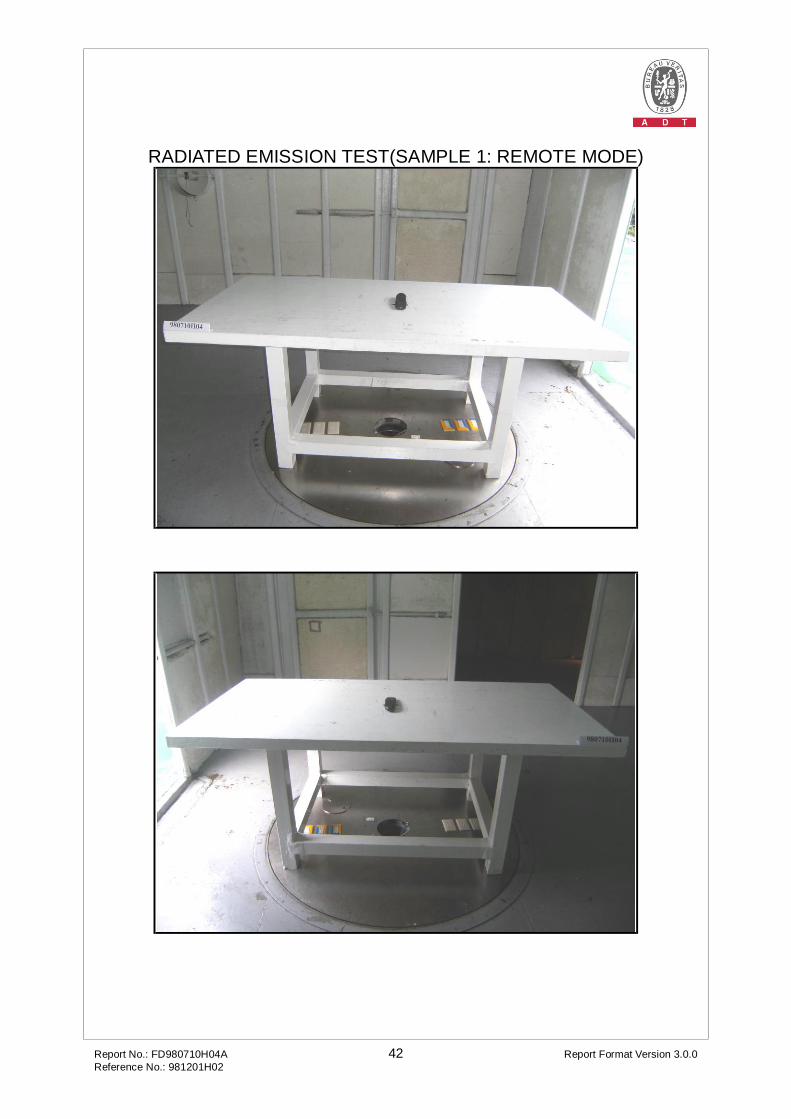
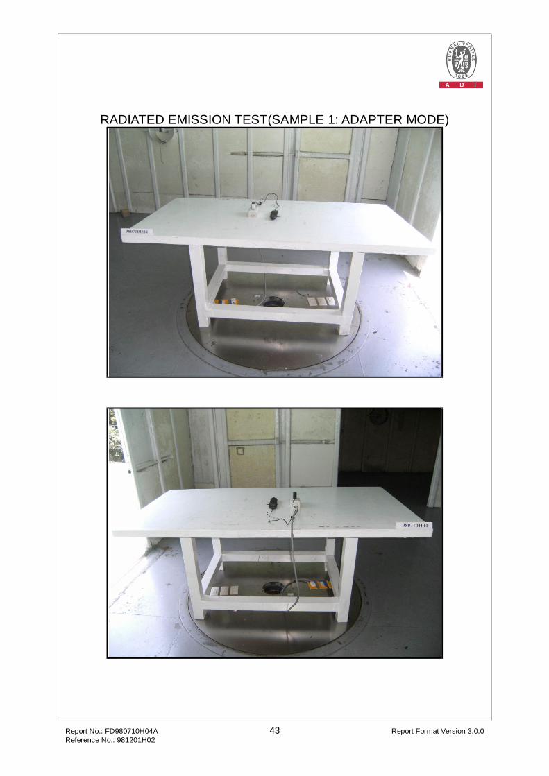
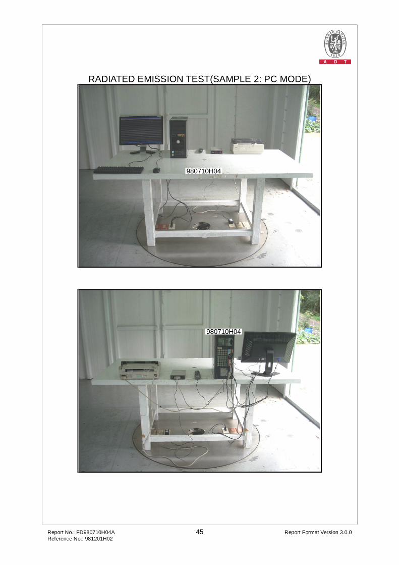
5 PHOTOGRAPHS OF THE TEST CONFIGURATION
CONDUCTED EMISSION TEST(SAMPLE 1: ADAPTER MODE)
Report No.: FD980710H04A 39 Report Format Version 3.0.0 Reference No.: 981201H02
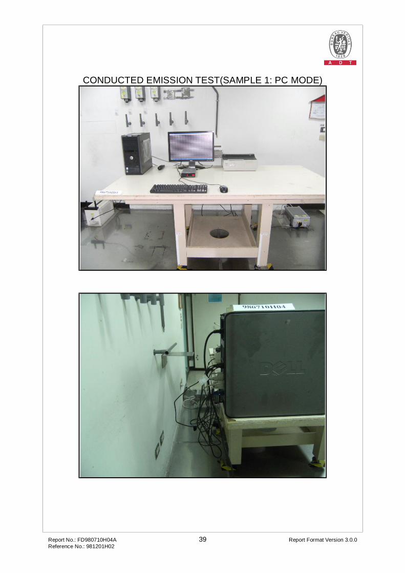
CONDUCTED EMISSION TEST(SAMPLE 1: PC MODE)
Report No.: FD980710H04A 40 Report Format Version 3.0.0 Reference No.: 981201H02
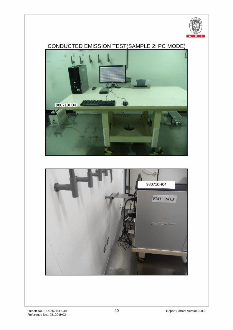
CONDUCTED EMISSION TEST(SAMPLE 2: PC MODE)
980710H04
980710H04

Report No.: FD980710H04A 41 Report Format Version 3.0.0 Reference No.: 981201H02
CONDUCTED EMISSION TEST(SAMPLE 3: PC MODE)
980710H04
980710H04
Report No.: FD980710H04A 42 Report Format Version 3.0.0 Reference No.: 981201H02
RADIATED EMISSION TEST(SAMPLE 1: REMOTE MODE)
Report No.: FD980710H04A 43 Report Format Version 3.0.0 Reference No.: 981201H02
RADIATED EMISSION TEST(SAMPLE 1: ADAPTER MODE)

Report No.: FD980710H04A 44 Report Format Version 3.0.0 Reference No.: 981201H02
RADIATED EMISSION TEST(SAMPLE 1: PC MODE)
Report No.: FD980710H04A 45 Report Format Version 3.0.0 Reference No.: 981201H02
RADIATED EMISSION TEST(SAMPLE 2: PC MODE)
980710H04
980710H04

Report No.: FD980710H04A 46 Report Format Version 3.0.0 Reference No.: 981201H02
RADIATED EMISSION TEST(SAMPLE 3: PC MODE)
980710H04
980710H04
Report No.: FD980710H04A 47 Report Format Version 3.0.0 Reference No.: 981201H02
6 INFORMATION ON THE TESTING LABORATORIES
We, Bureau Veritas Consumer Products Services (H.K.) Ltd., Taoyuan Branch, were founded in 1988 to provide our best service in EMC, Radio, Telecom and Safety consultation. Our laboratories are accredited and approved by the following approval agencies according to ISO/IEC 17025.
USA FCC, NVLAP Germany TUV Rheinland Japan VCCI Norway NEMKO Canada INDUSTRY CANADA, CSA R.O.C. TAF, BSMI, NCC Netherlands Telefication Singapore GOST-ASIA (MOU) Russia CERTIS (MOU)
Copies of accreditation certificates of our laboratories obtained from approval agencies can be downloaded from our web site: www.adt.com.tw/index.5/phtml. If you have any comments, please feel free to contact us at the following:
Linko EMC/RF Lab: Tel: 886-2-26052180 Fax: 886-2-26052943
Hsin Chu EMC/RF Lab: Tel: 886-3-5935343 Fax: 886-3-5935342
Hwa Ya EMC/RF/Safety/Telecom Lab: Tel: 886-3-3183232 Fax: 886-3-3185050
Email: [email protected] Web Site: www.adt.com.tw
The address and road map of all our labs can be found in our web site also.
Report No.: FD980710H04A 48 Report Format Version 3.0.0 Reference No.: 981201H02
7 APPENDIX A - MODIFICATIONS RECORDERS FOR ENGINEERING CHANGES TO THE EUT BY THE LAB
No any modifications are made to the EUT by the lab during the test. ---END---

Page 1
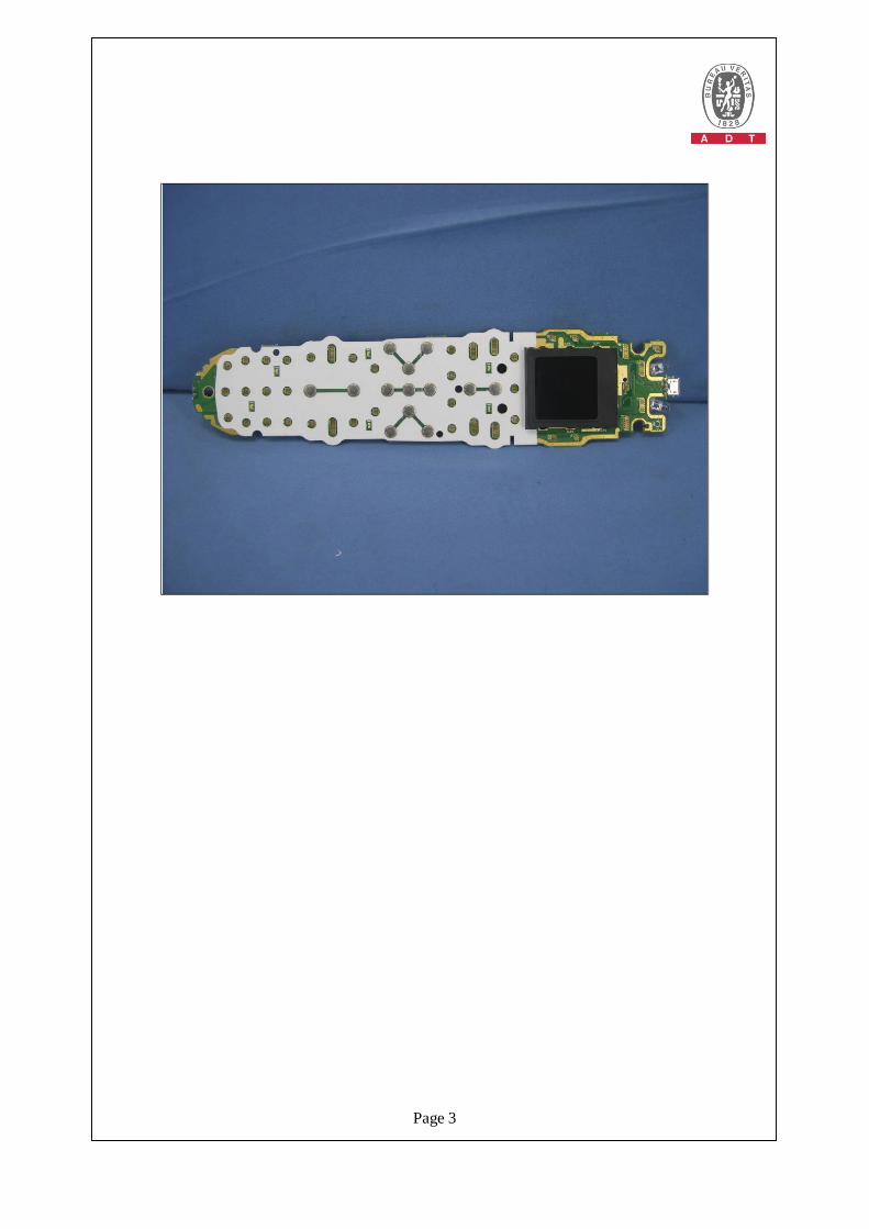
CONSTRUCTION PHOTOS OF EUT Product: Remote control Harmony 700

Page 2
Page 3

Page 4
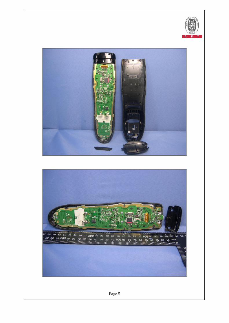
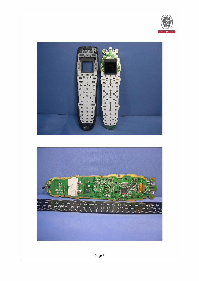
Product: Remote control Harmony 650
Page 5
Page 6

Page 7

Page 8
Product: Remote control Harmony 600
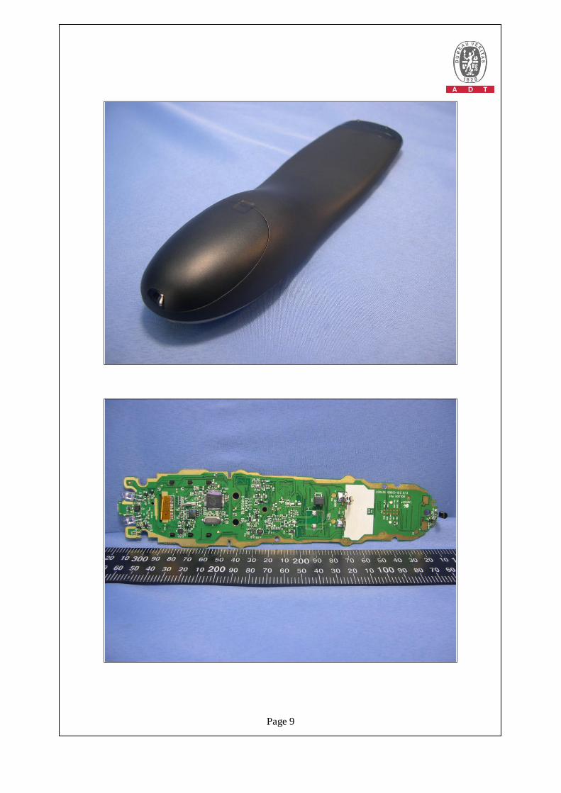
Page 9
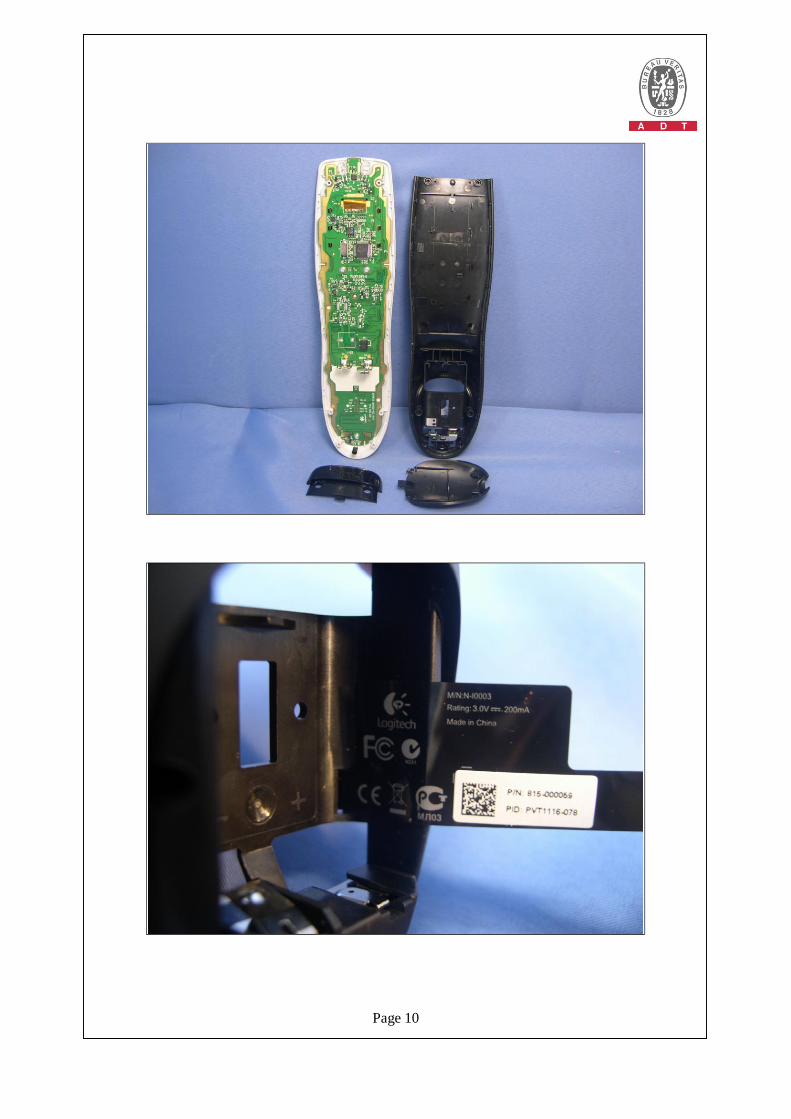
Page 10
Page 11
Page 12
Page 13