FCC Radio Test Report · fcc radio test report fcc id: yopgs2100mie ... attachment g - antenna...
103
Report No.: BTL-FCCP-1-1412211B Page 1 of 107 FCC Radio Test Report FCC ID: YOPGS2100MIE This report concerns (check one): Original Grant Class II Change Project No. : 1412211B Equipment : Wifi Module Model Name : GS2100MIE Applicant : Gainspan Corporation. Address : 3590 N. First Street Suite 300 San Jose California United States 95134. Date of Receipt : Jan. 21, 2015, Apr. 05, 2017 Date of Test : Jan. 21, 2015~Feb. 05, 2015 Apr. 05, 2017~ Apr. 10, 2017 Issued Date : May 03, 2017 Tested by : BTL Inc. Testing Engineer : (Josh Lin) Technical Manager : (Jeff Yang) Authorized Signatory : (Andy Chiu) BTL INC. B1, No. 37, Lane 365, Yang-Guang St., Nei-Hu District, Taipei City 114, Taiwan. TEL: +886-2-2657-3299 FAX: +886-2-2657-3331
Transcript of FCC Radio Test Report · fcc radio test report fcc id: yopgs2100mie ... attachment g - antenna...
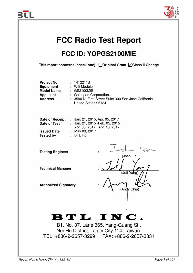
Report No.: BTL-FCCP-1-1412211B Page 1 of 107
FCC Radio Test Report
FCC ID: YOPGS2100MIE
This report concerns (check one): Original Grant Class II Change
Project No. : 1412211B Equipment : Wifi Module Model Name : GS2100MIE Applicant : Gainspan Corporation. Address : 3590 N. First Street Suite 300 San Jose California
United States 95134.
Date of Receipt : Jan. 21, 2015, Apr. 05, 2017 Date of Test : Jan. 21, 2015~Feb. 05, 2015
Apr. 05, 2017~ Apr. 10, 2017 Issued Date : May 03, 2017 Tested by : BTL Inc.
Testing Engineer :
(Josh Lin) Technical Manager :
(Jeff Yang) Authorized Signatory :
(Andy Chiu)
B T L I N C . B1, No. 37, Lane 365, Yang-Guang St., Nei-Hu District, Taipei City 114, Taiwan.
TEL: +886-2-2657-3299 FAX: +886-2-2657-3331
Report No.: BTL-FCCP-1-1412211B Page 2 of 107
Declaration
BTL represents to the client that testing is done in accordance with standard procedures as applicable and
that test instruments used has been calibrated with standards traceable to international standard(s) and/or
national standard(s).
BTL's reports apply only to the specific samples tested under conditions. It is manufacture’s responsibility to ensure that additional production units of this model are manufactured with the identical electrical and
mechanical components. BTL shall have no liability for any declarations, inferences or generalizations
drawn by the client or others from BTL issued reports.
BTL’s reports must not be used by the client to claim product endorsement by the authorities or any agency of the Government.
This report is the confidential property of the client. As a mutual protection to the clients, the public and
BTL-self, extracts from the test report shall not be reproduced except in full with BTL’s authorized written approval.
BTL’s laboratory quality assurance procedures are in compliance with the ISO Guide 17025 requirements,
and accredited by the conformity assessment authorities listed in this test report.
Limitation
For the use of the authority's logo is limited unless the Test Standard(s)/Scope(s)/Item(s) mentioned in this
test report is (are) included in the conformity assessment authorities acceptance respective.

Report No.: BTL-FCCP-1-1412211B Page 3 of 107
Table of Contents Page
1 . CERTIFICATION 6
2 . SUMMARY OF TEST RESULTS 7
2.1 TEST FACILITY 8
2.2 MEASUREMENT UNCERTAINTY 8
3 . GENERAL INFORMATION 10
3.1 GENERAL DESCRIPTION OF EUT 10
3.2 DESCRIPTION OF TEST MODES 12
3.3 TABLE OF PARAMETERS OF TEXT SOFTWARE SETTING 13
3.4 BLOCK DIAGRAM SHOWING THE CONFIGURATION OF SYSTEM TESTED 14
3.5 DESCRIPTION OF SUPPORT UNITS 14
4 . EMC EMISSION TEST 15
4.1 CONDUCTED EMISSION MEASUREMENT 15
4.1.1 POWER LINE CONDUCTED EMISSION LIMITS 15
4.1.2 TEST PROCEDURE 15
4.1.3 DEVIATION FROM TEST STANDARD 15
4.1.4 TEST SETUP 16
4.1.5 EUT OPERATING CONDITIONS 16
4.1.6 EUT TEST CONDITIONS 16
4.1.7 TEST RESULTS 16
4.2 RADIATED EMISSION MEASUREMENT 17
4.2.1 RADIATED EMISSION LIMITS 17
4.2.2 TEST PROCEDURE 18
4.2.3 DEVIATION FROM TEST STANDARD 18
4.2.4 TEST SETUP 18
4.2.5 EUT OPERATING CONDITIONS 19
4.2.6 EUT TEST CONDITIONS 19
4.2.7 TEST RESULTS (9KHZ TO 30MHZ) 20
4.2.7 TEST RESULTS (BETWEEN 30MHZ TO 1000 MHZ) 20
4.2.7 TEST RESULTS (ABOVE 1000 MHZ) 20
5 . BANDWIDTH TEST 21
5.1 APPLIED PROCEDURES 21
5.1.1 TEST PROCEDURE 21
5.1.2 DEVIATION FROM STANDARD 21
5.1.3 TEST SETUP 21
5.1.4 EUT OPERATION CONDITIONS 21
5.1.5 EUT TEST CONDITIONS 21
5.1.6 TEST RESULTS 21
Report No.: BTL-FCCP-1-1412211B Page 4 of 107
Table of Contents
Page
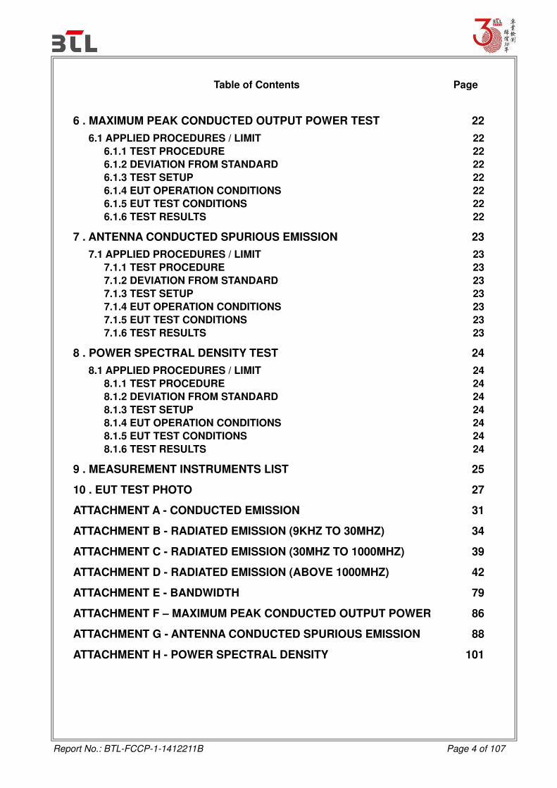
6 . MAXIMUM PEAK CONDUCTED OUTPUT POWER TEST 22
6.1 APPLIED PROCEDURES / LIMIT 22
6.1.1 TEST PROCEDURE 22
6.1.2 DEVIATION FROM STANDARD 22
6.1.3 TEST SETUP 22
6.1.4 EUT OPERATION CONDITIONS 22
6.1.5 EUT TEST CONDITIONS 22
6.1.6 TEST RESULTS 22
7 . ANTENNA CONDUCTED SPURIOUS EMISSION 23
7.1 APPLIED PROCEDURES / LIMIT 23
7.1.1 TEST PROCEDURE 23
7.1.2 DEVIATION FROM STANDARD 23
7.1.3 TEST SETUP 23
7.1.4 EUT OPERATION CONDITIONS 23
7.1.5 EUT TEST CONDITIONS 23
7.1.6 TEST RESULTS 23
8 . POWER SPECTRAL DENSITY TEST 24
8.1 APPLIED PROCEDURES / LIMIT 24
8.1.1 TEST PROCEDURE 24
8.1.2 DEVIATION FROM STANDARD 24
8.1.3 TEST SETUP 24
8.1.4 EUT OPERATION CONDITIONS 24
8.1.5 EUT TEST CONDITIONS 24
8.1.6 TEST RESULTS 24
9 . MEASUREMENT INSTRUMENTS LIST 25
10 . EUT TEST PHOTO 27
ATTACHMENT A - CONDUCTED EMISSION 31
ATTACHMENT B - RADIATED EMISSION (9KHZ TO 30MHZ) 34
ATTACHMENT C - RADIATED EMISSION (30MHZ TO 1000MHZ) 39
ATTACHMENT D - RADIATED EMISSION (ABOVE 1000MHZ) 42
ATTACHMENT E - BANDWIDTH 79
ATTACHMENT F – MAXIMUM PEAK CONDUCTED OUTPUT POWER 86
ATTACHMENT G - ANTENNA CONDUCTED SPURIOUS EMISSION 88
ATTACHMENT H - POWER SPECTRAL DENSITY 101

Report No.: BTL-FCCP-1-1412211B Page 5 of 107
REPORT ISSUED HISTORY
Issued No. Description Issued Date
R1404031-247 Original Report. Jun.17, 2014
BTL-FCCP-1-1412211
Compared with the previous report (R1404031-247), Added a new PCB antenna, the gain value (3.56 dBi) is higher than the original PCB antenna (1 dBi). All tests are performed and test results are recorded in this report.
Feb.06, 2015
BTL-FCCP-1-1412211B
Compared with the previous report (BTL-FCCP-1-1412211), A. Added two new different type (Dipole)
antennas, antenna 1 gain value (3.29 dBi) and antenna 2 gain value (3.02 dBi) are Lower than the original PCB antenna (3.56 dBi).
B. Updated standard version. Conducted Emission and Radiated Emissions test results has been re-evaluated and recorded in the test report. Others test results are kept the same.
May 03, 2017

Report No.: BTL-FCCP-1-1412211B Page 6 of 107
1. CERTIFICATION Equipment : Wifi Module Brand Name : XYZprinting Model Name : GS2100MIE
Applicant : Gainspan Corporation. Manufacturer : Cal-Comp Electronics (Thailand) Public Company Limited
Address : 138, Moo 4, Phechkasem Road, Sapang, Koawyoi, Petchaburi 76140,
Thailand. Factory : Cal-Comp Electronics (Thailand) Public Company Limited
Address : 138, Moo 4, Phechkasem Road, Sapang, Koawyoi, Petchaburi 76140,
Thailand.
Date of Test : Jan. 21, 2015~Feb. 05, 2015
Apr. 05, 2017~ Apr. 10, 2017 Test Sample : Engineering Sample Standard(s) : FCC Part15, Subpart C (15.247) / ANSI C63.10-2013 The above equipment has been tested and found in compliance with the requirement of the relative standards by BTL Inc. The test data, data evaluation, and equipment configuration contained in our test report (Ref No. BTL-FCCP-1-1412211B) were obtained utilizing the test procedures, test instruments, test sites that has been accredited by the Authority of TAF according to the ISO-17025 quality assessment standard and technical standard(s).

Report No.: BTL-FCCP-1-1412211B Page 7 of 107
2. SUMMARY OF TEST RESULTS Test procedures according to the technical standard(s):
Applied Standard(s): FCC Part15 (15.247) , Subpart C
Standard(s) Section Test Item Judgment Remark
FCC
15.207 Conducted Emission PASS
15.247(d) Antenna conducted Spurious Emission
PASS
15.247(a)(2) 6dB Bandwidth PASS
15.247(b)(3) Peak Output Power PASS
15.247(e) Power Spectral Density PASS
15.203 Antenna Requirement PASS
15.209/15.205 Transmitter Radiated
Emissions PASS
NOTE:
(1)” N/A” denotes test is not applicable in this test report.
(2) The test follows FCC KDB Publication No. 558074 D01 DTS Meas Guidance v03r02
(Measurement Guidelines of DTS)

Report No.: BTL-FCCP-1-1412211B Page 8 of 107
2.1TEST FACILITY The test facilities used to collect the test data in this report:
Conducted emission Test: C05: (VCCI RN: C-4742; FCC RN:674415; FCC DN:TW0659)
No. 68-1, Ln. 169, Sec.2, Datong Rd., Xizhi Dist., New Taipei City 221, Taiwan
Radiated emission Test (Below 1 GHz): CB15: (FCC RN:674415; FCC DN:TW0659)
No. 68-1, Ln. 169, Sec.2, Datong Rd., Xizhi Dist., New Taipei City 221, Taiwan
Radiated emission Test (Above 1 GHz): CB15: (FCC RN:674415; FCC DN:TW0659)
No. 68-1, Ln. 169, Sec.2, Datong Rd., Xizhi Dist., New Taipei City 221, Taiwan
2.2MEASUREMENT UNCERTAINTY
The measurement uncertainty is not specified by Canada Industry for reference only. The reported uncertainty of measurement y ± U,where expended uncertainty U is based on a standard uncertainty multiplied by a coverage factor of k=2,providing a level of confidence of approximately 95%. The measurement instrumentation uncertainty considerations contained in CISPR 16-4-2.
A. Conducted emission test:
Test Site Method Measurement Frequency Range U,(dB)
C05 CISPR 150 kHz ~ 30MHz 3.06
B. Radiated emission test:
Test Site Method Measurement Frequency Range U,(dB)
CB15 (3m)
CISPR 9kHz ~ 150kHz 2.96
150kHz ~ 30MHz 2.74
Test Site Method Measurement Frequency Range Ant. H / V
U,(dB)
CB15 (3m)
CISPR
30MHz ~ 200MHz V 4.76
30MHz ~ 200MHz H 4.28
200MHz ~ 1,000MHz V 5.08
200MHz ~ 1,000MHz H 4.50
Test Site Method Measurement Frequency Range Ant. H / V
U,(dB)
CB15 (3m)
CISPR
1GHz ~ 6GHz V 4.48
1GHz ~ 6GHz H 4.50
6GHz ~ 18GHz V 4.30
6GHz ~ 18GHz H 4.14
Test Site Method Measurement Frequency Range U,(dB)
CB15 (1m)
CISPR 18 ~ 26.5 GHz 4.72
26.5 ~ 40 GHz 5.20
Report No.: BTL-FCCP-1-1412211B Page 9 of 107
Our calculated Measurement Instrumentation Uncertainty is shown in the tables above.
These are our Ulab values in CISPR 16-4-2 terminology. Since Table 1 of CISPR 16-4-2 has values of measurement instrumentation uncertainty, called UCISPR, as follows:
Conducted Disturbance (mains port) – 150 kHz – 30 MHz: 3.6 dB Radiated Disturbance (electric field strength on an open area test site or alternative test site) – 30 MHz – 1000 MHz: 5.2 dB
It can be seen that our Ulab values are smaller than UCISPR. Note: unless specifically mentioned, the uncertainty of measurement has not been taken into account to declare the compliance or non-compliance to the specification.

Report No.: BTL-FCCP-1-1412211B Page 10 of 107
3. GENERAL INFORMATION
3.1 GENERAL DESCRIPTION OF EUT
Equipment Wifi Module
Brand Name XYZprinting
Model Name GS2100MIE
Model Difference N/A
Product Description
Operation Frequency 2412~2462 MHz
Modulation Technology 802.11b:DSSS 802.11g:OFDM 802.11n:OFDM
Bit Rate of Transmitter
802.11b: 11/5.5/2/1 Mbps 802.11g: 54/48/36/24/18/12/9/6 Mbps 802.11n up to 72.2 Mbps
Output Power (Max.) 802.11b: 14.94dBm 802.11g: 19.48dBm 802.11n(20MHz): 19.45dBm
Power Source System supplied.
Power Rating DC 3.3V/355mA
Note:
1. For a more detailed features description, please refer to the manufacturer’s specifications or the User's Manual.
2. Channel List:
CH01 – CH11 for 802.11b, 802.11g, 802.11n(20MHz)
Channel Frequency
(MHz) Channel
Frequency
(MHz) Channel
Frequency
(MHz) Channel
Frequency
(MHz)
01 2412 04 2427 07 2442 10 2457 02 2417 05 2432 08 2447 11 2462 03 2422 06 2437 09 2452
Report No.: BTL-FCCP-1-1412211B Page 11 of 107
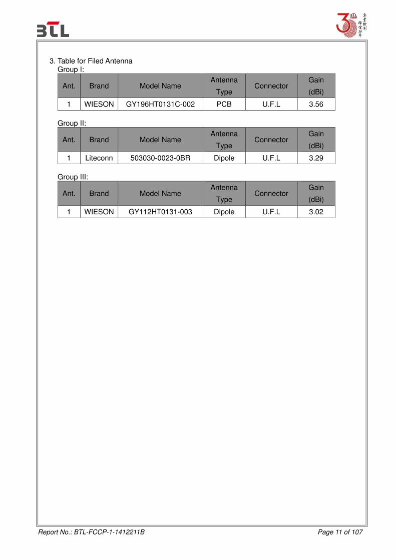
3. Table for Filed Antenna
Group I:
Ant. Brand Model Name Antenna
Type Connector
Gain
(dBi)
1 WIESON GY196HT0131C-002 PCB U.F.L 3.56
Group II:
Ant. Brand Model Name Antenna
Type Connector
Gain
(dBi)
1 Liteconn 503030-0023-0BR Dipole U.F.L 3.29
Group III:
Ant. Brand Model Name Antenna
Type Connector
Gain
(dBi)
1 WIESON GY112HT0131-003 Dipole U.F.L 3.02

Report No.: BTL-FCCP-1-1412211B Page 12 of 107
3.2 DESCRIPTION OF TEST MODES
To investigate the maximum EMI emission characteristics generates from EUT, the test system was pre-scanning tested base on the consideration of following EUT operation mode or test configuration mode which possible have effect on EMI emission level. Each of these EUT operation mode(s) or test configuration mode(s) mentioned above was evaluated respectively.
Pretest Mode Description
Mode 1 TX B MODE CHANNEL 01/06/11
Mode 2 TX G MODE CHANNEL 01/06/11
Mode 3 TX N-20MHZ MODE CHANNEL 01/06/11
Mode 4 TX MODE
The EUT system operated these modes were found to be the worst case during the pre-scanning test as following:
For Conducted Test
Final Test Mode Description
Mode 4 TX MODE
For Radiated Test
Final Test Mode Description
Mode 1 TX B MODE CHANNEL 01/06/11
Mode 2 TX G MODE CHANNEL 01/06/11
Mode 3 TX N-20MHZ MODE CHANNEL 01/06/11
Note:
(1) The measurements are performed at the high, middle, low available channels.
(2) 802.11b mode: DBPSK (1Mbps) 802.11g mode: OFDM (6Mbps) 802.11n HT20 mode : BPSK (6.5Mbps) For radiated emission tests, the highest output powers were set for final test.
(3) For radiated below 1G test, the 802.11b is found to be the worst case and recorded.
(4) The EUT was programmed to be in continuously transmitting mode and the transmit duty
cycle is not less than 98%.

Report No.: BTL-FCCP-1-1412211B Page 13 of 107
3.3 TABLE OF PARAMETERS OF TEXT SOFTWARE SETTING
During testing, channel & power controlling software provided by the customer was used to control the operating channel as well as the output power level. The RF output power selection is for the setting of RF output power expected by the customer and is going to be fixed on the firmware of the final end product power parameters of WLAN
Test software version teraterm-4.84
Frequency (MHz) 2412 2437 2462
802.11b 18 18 18
802.11g 27 27 27
802.11n (20MHz) 27 27 27

Report No.: BTL-FCCP-1-1412211B Page 14 of 107
3.4 BLOCK DIAGRAM SHOWING THE CONFIGURATION OF SYSTEM TESTED
3.5 DESCRIPTION OF SUPPORT UNITS
The EUT has been tested as an independent unit together with other necessary accessories or support units. The following support units or accessories were used to form a representative test configuration during the tests.
Item Equipment Mfr/Brand Model/Type No. FCC ID/IC Series No. Note
- PCB(Fixture) N/A N/A N/A N/A
- Adapter FSP FSP060-DIBAN2 N/A N/A
Item Shielded Type Ferrite Core Length Note
1 NO Yes 1.2M Power Cable
Report No.: BTL-FCCP-1-1412211B Page 15 of 107
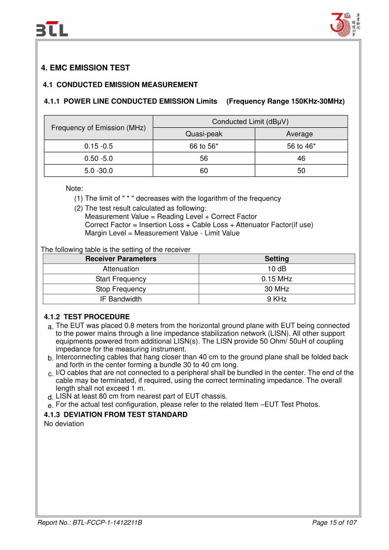
4. EMC EMISSION TEST 4.1 CONDUCTED EMISSION MEASUREMENT 4.1.1 POWER LINE CONDUCTED EMISSION Limits (Frequency Range 150KHz-30MHz)
Frequency of Emission (MHz) Conducted Limit (dBμV)
Quasi-peak Average
0.15 -0.5 66 to 56* 56 to 46*
0.50 -5.0 56 46
5.0 -30.0 60 50
Note:
(1) The limit of " * " decreases with the logarithm of the frequency
(2) The test result calculated as following: Measurement Value = Reading Level + Correct Factor Correct Factor = Insertion Loss + Cable Loss + Attenuator Factor(if use) Margin Level = Measurement Value - Limit Value
The following table is the setting of the receiver
Receiver Parameters Setting
Attenuation 10 dB
Start Frequency 0.15 MHz
Stop Frequency 30 MHz
IF Bandwidth 9 KHz
4.1.2 TEST PROCEDURE
a. The EUT was placed 0.8 meters from the horizontal ground plane with EUT being connected to the power mains through a line impedance stabilization network (LISN). All other support equipments powered from additional LISN(s). The LISN provide 50 Ohm/ 50uH of coupling impedance for the measuring instrument.
b. Interconnecting cables that hang closer than 40 cm to the ground plane shall be folded back and forth in the center forming a bundle 30 to 40 cm long.
c. I/O cables that are not connected to a peripheral shall be bundled in the center. The end of the cable may be terminated, if required, using the correct terminating impedance. The overall length shall not exceed 1 m.
d. LISN at least 80 cm from nearest part of EUT chassis.
e. For the actual test configuration, please refer to the related Item –EUT Test Photos.
4.1.3 DEVIATION FROM TEST STANDARD
No deviation

Report No.: BTL-FCCP-1-1412211B Page 16 of 107
4.1.4 TEST SETUP
Note: 1.Support units were connected to second LISN.
2.Both of LISNs (AMN) are 80 cm from EUT and at least 80
from other units and other metal planes
Vertical Reference
Ground Plane
40cm
80cm
Test Receiver
Horizontal ReferenceGround Plane
EUT
LISN
4.1.5 EUT OPERATING CONDITIONS
The EUT was configured for testing in a typical fashion (as a customer would normally use it). The EUT has been programmed to continuously transmit during test. This operating condition was tested and used to collect the included data.
4.1.6 EUT TEST CONDITIONS
Temperature: 25°C Relative Humidity: 55% Test Voltage: AC 120V/60Hz
4.1.7 TEST RESULTS
Please refer to the Attachment A.

Report No.: BTL-FCCP-1-1412211B Page 17 of 107
4.2 RADIATED EMISSION MEASUREMENT
4.2.1 RADIATED EMISSION LIMITS
20dB in any 100 KHz bandwidth outside the operating frequency band. In case the emission fall within the restricted band specified on 15.205(a), then the 15.209(a) limit in the table below has to be followed.
LIMITS OF RADIATED EMISSION MEASUREMENT (9KHz-1000MHz)
Frequency
(MHz)
Field Strength
(microvolts/meter)
Measurement Distance
(meters)
0.009~0.490 2400/F(KHz) 300
0.490~1.705 24000/F(KHz) 30
1.705~30.0 30 30
30~88 100 3
88~216 150 3
216~960 200 3
960~1000 500 3
LIMITS OF RADIATED EMISSION MEASUREMENT (Above 1000MHz)
Frequency (MHz) (dBuV/m) (at 3 meters)
PEAK AVERAGE
Above 1000 74 54
Notes:
(1) The limit for radiated test was performed according to FCC PART 15C.
(2) The tighter limit applies at the band edges.
(3) Emission level (dBuV/m)=20log Emission level (uV/m).
(4) The test result calculated as following: Measurement Value = Reading Level + Correct Factor Correct Factor = Antenna Factor + Cable Loss - Amplifier Gain(if use) Margin Level = Measurement Value - Limit Value
Spectrum Parameter Setting
Attenuation Auto
Start Frequency 1000 MHz
Stop Frequency 10th carrier harmonic
RBW / VBW
(Emission in restricted band)
RBW 1MHz VBW 3MHz peak detector for Pk value
RMS detector for AV value

Report No.: BTL-FCCP-1-1412211B Page 18 of 107
Receiver Parameter Setting
Attenuation Auto
Start ~ Stop Frequency 9KHz~90KHz for PK/AVG detector
Start ~ Stop Frequency 90KHz~110KHz for QP detector
Start ~ Stop Frequency 110KHz~490KHz for PK/AVG detector
Start ~ Stop Frequency 490KHz~30MHz for QP detector
Start ~ Stop Frequency 30MHz~1000MHz for QP detector
4.2.2 TEST PROCEDURE
a. The EUT was placed on the top of a rotating table 0.8 meters above the ground at a 3 meter semi-anechoic chamber. The table was rotated 360 degrees to determine the position of the highest radiation.(below 1GHz)
b. The EUT was placed on the top of a rotating table 0.8 meters above the ground at a 3 meter fully-anechoic chamber. The table was rotated 360 degrees to determine the position of the highest radiation.(above 1GHz)
c. The height of the equipment or of the substitution antenna shall be 0.8 m; the height of the test antenna shall vary between 1 m to 4 m. Both horizontal and vertical polarizations of the antenna are set to make the measurement.
d. The initial step in collecting conducted emission data is a spectrum analyzer peak detector mode pre-scanning the measurement frequency range. Significant peaks are then marked and then Quasi Peak detector mode re-measured.
e. If the Peak Mode measured value compliance with and lower than Quasi Peak Mode Limit, the EUT shall be deemed to meet QP Limits and then no additional QP Mode measurement performed.
f. For the actual test configuration, please refer to the related Item –EUT Test Photos.
4.2.3 DEVIATION FROM TEST STANDARD
No deviation
4.2.4 TEST SETUP
(A) Radiated Emission Test Set-Up Frequency Below 1 GHz
Amp.
EUT
1-4 m
3 m
Receiver
0.8 m
Absorbers
Ground Plane
1 m

Report No.: BTL-FCCP-1-1412211B Page 19 of 107
(B) Radiated Emission Test Set-Up Frequency Above 1 GHz
(C) For radiated emissions below 30MHz
4.2.5 EUT OPERATING CONDITIONS
The EUT tested system was configured as the statements of 4.1.5 Unless otherwise a special operating condition is specified in the follows during the testing.
4.2.6 EUT TEST CONDITIONS
Temperature: 23°C Relative Humidity: 70% Test Voltage: AC 120V/60Hz
Report No.: BTL-FCCP-1-1412211B Page 20 of 107
4.2.7 TEST RESULTS (9KHZ TO 30MHZ)
Please refer to the Attachment B
Remark: (1) The amplitude of spurious emissions which are attenuated by more than 20 dB below the permissible value has no need to be reported.
(2) Distance extrapolation factor = 40 log (specific distance / test distance) (dB). (3) Limit line = specific limits (dBuV) + distance extrapolation factor.
4.2.7 TEST RESULTS (BETWEEN 30MHZ TO 1000 MHZ)
Please refer to the Attachment C.
4.2.7 TEST RESULTS (ABOVE 1000 MHZ)
Please refer to the Attachment D.
Remark: (1) No limit: This is fundamental signal, the judgment is not applicable. For fundamental signal judgment was referred to Peak output test.

Report No.: BTL-FCCP-1-1412211B Page 21 of 107
5. BANDWIDTH TEST
5.1 APPLIED PROCEDURES
FCC Part15 (15.247) , Subpart C
Section Test Item Frequency Range
(MHz) Result
15.247(a)(2) Bandwidth 2400-2483.5 PASS
5.1.1 TEST PROCEDURE
a. The EUT was directly connected to the spectrum analyzer and antenna output port as show in
the block diagram below,
b. Spectrum Setting: RBW= 100KHz, VBW=300KHz, Sweep time = 2.5 ms.
5.1.2 DEVIATION FROM STANDARD
No deviation.
5.1.3 TEST SETUP
5.1.4 EUT OPERATION CONDITIONS
The EUT tested system was configured as the statements of 4.1.5 Unless otherwise a special operating condition is specified in the follows during the testing.
5.1.5 EUT TEST CONDITIONS
Temperature: 25°C Relative Humidity: 55% Test Voltage: AC 120V/60Hz
5.1.6 TEST RESULTS
Please refer to the Attachment E.

Report No.: BTL-FCCP-1-1412211B Page 22 of 107
6. MAXIMUM PEAK CONDUCTED OUTPUT POWER TEST
6.1 APPLIED PROCEDURES / LIMIT
FCC Part15 (15.247) , Subpart C
Section Test Item Limit Frequency Range
(MHz) Result
15.247(b)(3) Maximum Output
Power 1 Watt or 30dBm 2400-2483.5 PASS
6.1.1 TEST PROCEDURE
a. The EUT was directly connected to the power meter and antenna output port as show in the
block diagram below, b. The maximum peak conducted output power was performed in accordance with method 9.1.2
of FCC KDB 558074 D01 DTS Meas Guidance v03r02.
6.1.2 DEVIATION FROM STANDARD
No deviation.
6.1.3 TEST SETUP
6.1.4 EUT OPERATION CONDITIONS The EUT tested system was configured as the statements of 4.1.5 Unless otherwise a special operating condition is specified in the follows during the testing. Transmit output power was measured while the host equipment supply voltage was varied from 85 % to 115 % of the nominal rated supply voltage. No change in transmit output power was observed.
6.1.5 EUT TEST CONDITIONS
Temperature: 25°C Relative Humidity: 55% Test Voltage: AC 120V/60Hz
6.1.6 TEST RESULTS
Please refer to the Attachment F.

Report No.: BTL-FCCP-1-1412211B Page 23 of 107
7. ANTENNA CONDUCTED SPURIOUS EMISSION
7.1 APPLIED PROCEDURES / LIMIT In any 100 kHz bandwidth outside the frequency band in which the spread spectrum or digitally modulated intentional radiator is operating, the radio frequency power that is produced by the intentional radiator shall be at least 20 dB below that in the 100 kHz bandwidth within the band that contains the highest level of the desired power, based on either an RF conducted measurement, provided the transmitter demonstrates compliance with the peak conducted power limits.
7.1.1 TEST PROCEDURE
a. The EUT was directly connected to the spectrum analyzer and antenna output port as show in
the block diagram below,
b. Spectrum Setting: RBW= 100KHz, VBW=300KHz, Sweep time = Auto.
7.1.2 DEVIATION FROM STANDARD
No deviation.
7.1.3 TEST SETUP
7.1.4 EUT OPERATION CONDITIONS
The EUT tested system was configured as the statements of 4.1.5 Unless otherwise a special operating condition is specified in the follows during the testing.
7.1.5 EUT TEST CONDITIONS
Temperature: 25°C Relative Humidity: 55% Test Voltage: AC 120V/60Hz
7.1.6 TEST RESULTS
Please refer to the Attachment G.

Report No.: BTL-FCCP-1-1412211B Page 24 of 107
8. POWER SPECTRAL DENSITY TEST
8.1 APPLIED PROCEDURES / LIMIT
FCC Part15 (15.247) , Subpart C
Section Test Item Limit Frequency Range
(MHz) Result
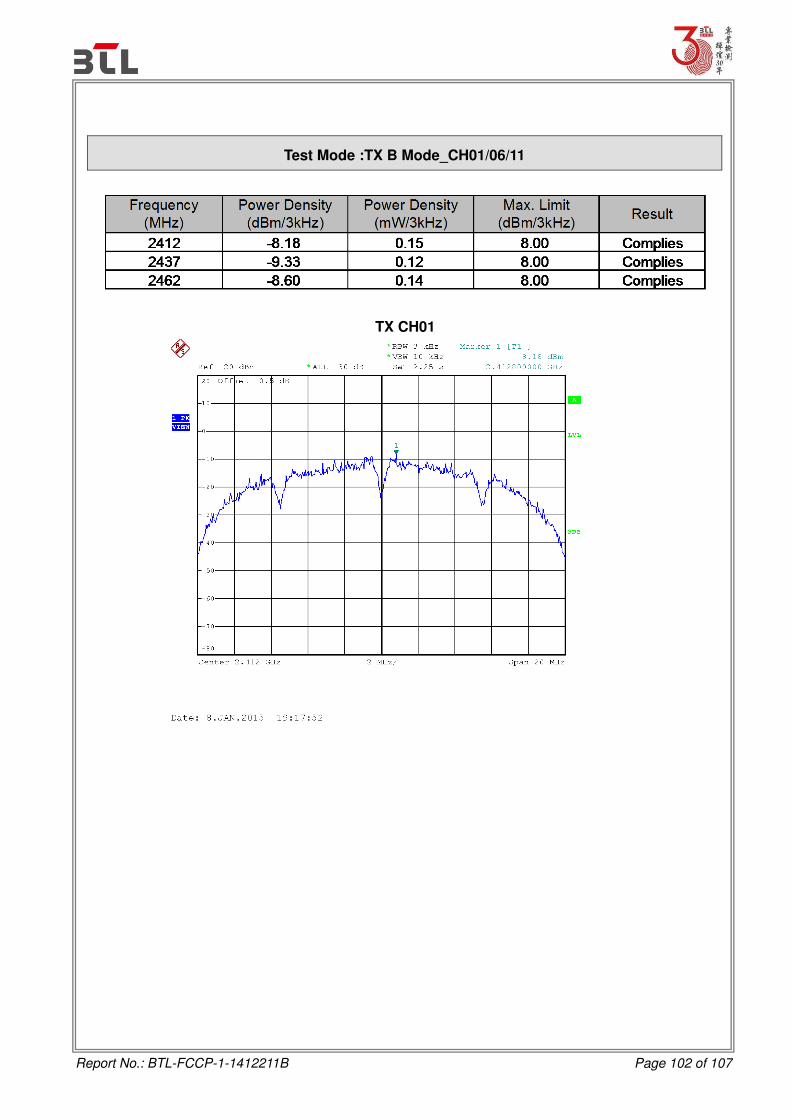
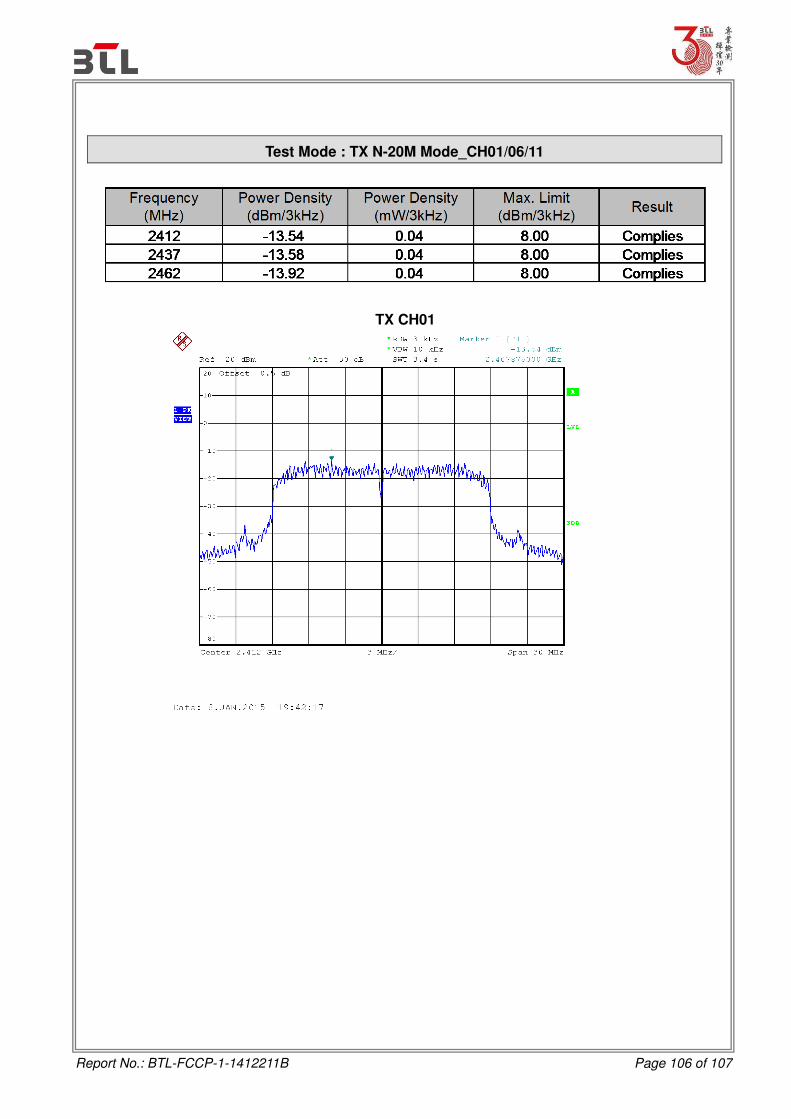
15.247(e) Power Spectral Density 8 dBm
(in any 3KHz) 2400-2483.5 PASS
8.1.1 TEST PROCEDURE
a. The EUT was directly connected to the spectrum analyzer and antenna output port as show in
the block diagram below,
b. Spectrum Setting: RBW=3KHz, VBW=10KHz, Sweep time = Auto.
8.1.2 DEVIATION FROM STANDARD
No deviation.
8.1.3 TEST SETUP
8.1.4 EUT OPERATION CONDITIONS
The EUT tested system was configured as the statements of 4.1.5 Unless otherwise a special operating condition is specified in the follows during the testing.
8.1.5 EUT TEST CONDITIONS
Temperature: 25°C Relative Humidity: 55% Test Voltage: AC 120V/60Hz
8.1.6 TEST RESULTS
Please refer to the Attachment H.
Report No.: BTL-FCCP-1-1412211B Page 25 of 107
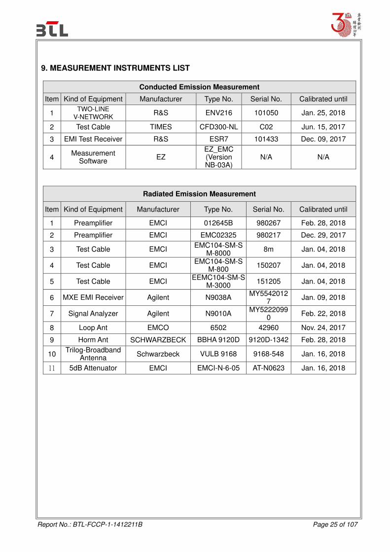
9. MEASUREMENT INSTRUMENTS LIST
Conducted Emission Measurement
Item Kind of Equipment Manufacturer Type No. Serial No. Calibrated until
1 TWO-LINE
V-NETWORK R&S ENV216 101050 Jan. 25, 2018
2 Test Cable TIMES CFD300-NL C02 Jun. 15, 2017
3 EMI Test Receiver R&S ESR7 101433 Dec. 09, 2017
4 Measurement
Software EZ
EZ_EMC (Version NB-03A)
N/A N/A
Radiated Emission Measurement
Item Kind of Equipment Manufacturer Type No. Serial No. Calibrated until
1 Preamplifier EMCI 012645B 980267 Feb. 28, 2018
2 Preamplifier EMCI EMC02325 980217 Dec. 29, 2017
3 Test Cable EMCI EMC104-SM-S
M-8000 8m Jan. 04, 2018
4 Test Cable EMCI EMC104-SM-S
M-800 150207 Jan. 04, 2018
5 Test Cable EMCI EEMC104-SM-S
M-3000 151205 Jan. 04, 2018
6 MXE EMI Receiver Agilent N9038A MY5542012
7 Jan. 09, 2018
7 Signal Analyzer Agilent N9010A MY5222099
0 Feb. 22, 2018
8 Loop Ant EMCO 6502 42960 Nov. 24, 2017
9 Horm Ant SCHWARZBECK BBHA 9120D 9120D-1342 Feb. 28, 2018
10 Trilog-Broadband
Antenna Schwarzbeck VULB 9168 9168-548 Jan. 16, 2018
11 5dB Attenuator EMCI EMCI-N-6-05 AT-N0623 Jan. 16, 2018

Report No.: BTL-FCCP-1-1412211B Page 26 of 107
6dB Bandwidth Measurement
Item Kind of Equipment Manufacturer Type No. Serial No. Calibrated until
1 Spectrum Analyzer R&S FSP30 100854 Oct. 26, 2015
Peak Output Power Measurement
Item Kind of Equipment Manufacturer Type No. Serial No. Calibrated until
1 Spectrum Analyzer R&S FSP30 100854 Oct. 26, 2015
Antenna Conducted Spurious Emission Measurement
Item Kind of Equipment Manufacturer Type No. Serial No. Calibrated until
1 Spectrum Analyzer R&S FSP30 100854 Oct. 26, 2015
Power Spectral Density Measurement
Item Kind of Equipment Manufacturer Type No. Serial No. Calibrated until
1 Spectrum Analyzer R&S FSP30 100854 Oct. 26, 2015
Remark: ”N/A” denotes no model name, serial no. or calibration specified. All calibration period of equipment list is one year.

Report No.: BTL-FCCP-1-1412211B Page 31 of 107
ATTACHMENT A - CONDUCTED EMISSION

Report No.: BTL-FCCP-1-1412211B Page 32 of 107
Test Mode : TX MODE
Line

Report No.: BTL-FCCP-1-1412211B Page 33 of 107
Test Mode : TX MODE
Neutral

Report No.: BTL-FCCP-1-1412211B Page 34 of 107
ATTACHMENT B - RADIATED EMISSION (9KHZ TO 30MHZ)

Report No.: BTL-FCCP-1-1412211B Page 35 of 107
Test Mode: TX
OPEN
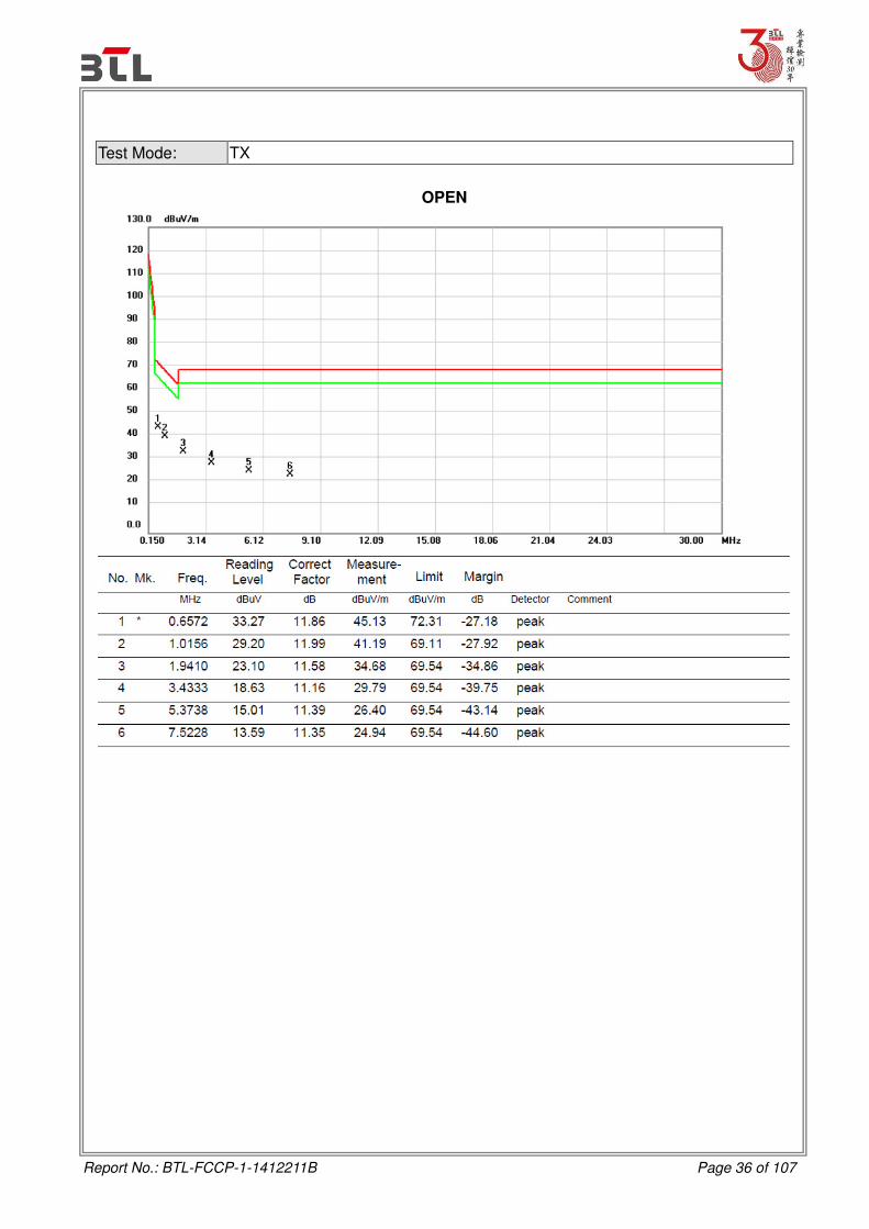
Report No.: BTL-FCCP-1-1412211B Page 36 of 107
Test Mode: TX
OPEN

Report No.: BTL-FCCP-1-1412211B Page 37 of 107
Test Mode: TX
CLOSE

Report No.: BTL-FCCP-1-1412211B Page 38 of 107
Test Mode: TX
CLOSE

Report No.: BTL-FCCP-1-1412211B Page 39 of 107
ATTACHMENT C - RADIATED EMISSION (30MHZ TO 1000MHZ)

Report No.: BTL-FCCP-1-1412211B Page 40 of 107
Test Mode: TX N-20M MODE 2462MHz
Vertical
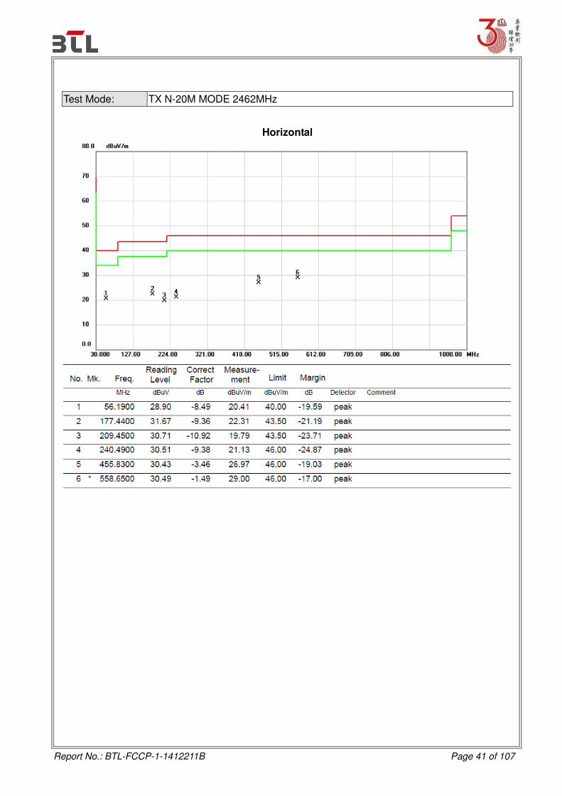
Report No.: BTL-FCCP-1-1412211B Page 41 of 107
Test Mode: TX N-20M MODE 2462MHz
Horizontal
Report No.: BTL-FCCP-1-1412211B Page 42 of 107
ATTACHMENT D - RADIATED EMISSION (ABOVE 1000MHZ)

Report No.: BTL-FCCP-1-1412211B Page 43 of 107
Orthogonal Axis : X
Test Mode : TX B MODE 2412MHz
Vertical

Report No.: BTL-FCCP-1-1412211B Page 44 of 107
Orthogonal Axis : X
Test Mode : TX B MODE 2412MHz
Vertical
Report No.: BTL-FCCP-1-1412211B Page 45 of 107
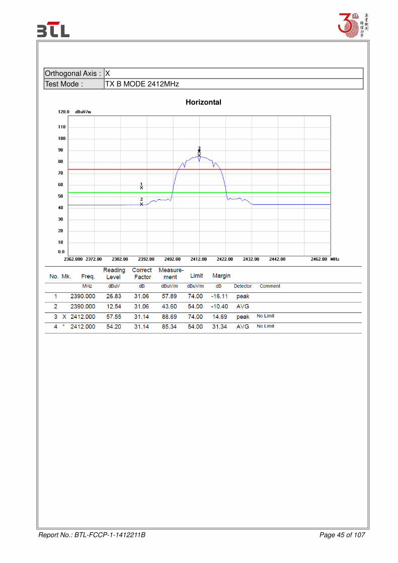
Orthogonal Axis : X
Test Mode : TX B MODE 2412MHz
Horizontal

Report No.: BTL-FCCP-1-1412211B Page 46 of 107
Orthogonal Axis : X
Test Mode : TX B MODE 2412MHz
Horizontal

Report No.: BTL-FCCP-1-1412211B Page 47 of 107
Orthogonal Axis : X
Test Mode : TX B MODE 2437MHz
Vertical

Report No.: BTL-FCCP-1-1412211B Page 48 of 107
Orthogonal Axis : X
Test Mode : TX B MODE 2437MHz
Vertical

Report No.: BTL-FCCP-1-1412211B Page 49 of 107
Orthogonal Axis : X
Test Mode : TX B MODE 2437MHz
Horizontal

Report No.: BTL-FCCP-1-1412211B Page 50 of 107
Orthogonal Axis : X
Test Mode : TX B MODE 2437MHz
Horizontal

Report No.: BTL-FCCP-1-1412211B Page 51 of 107
Orthogonal Axis : X
Test Mode : TX B MODE 2462MHz
Vertical
Report No.: BTL-FCCP-1-1412211B Page 52 of 107
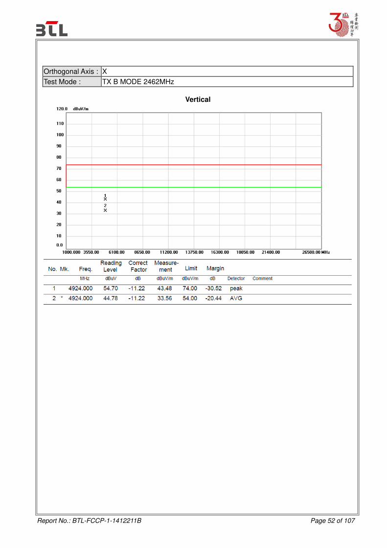
Orthogonal Axis : X
Test Mode : TX B MODE 2462MHz
Vertical

Report No.: BTL-FCCP-1-1412211B Page 53 of 107
Orthogonal Axis : X
Test Mode : TX B MODE 2462MHz
Horizontal

Report No.: BTL-FCCP-1-1412211B Page 54 of 107
Orthogonal Axis : X
Test Mode : TX B MODE 2462MHz
Horizontal

Report No.: BTL-FCCP-1-1412211B Page 55 of 107
Orthogonal Axis : X
Test Mode : TX G MODE 2412MHz
Vertical

Report No.: BTL-FCCP-1-1412211B Page 56 of 107
Orthogonal Axis : X
Test Mode : TX G MODE 2412MHz
Vertical

Report No.: BTL-FCCP-1-1412211B Page 57 of 107
Orthogonal Axis : X
Test Mode : TX G MODE 2412MHz
Horizontal

Report No.: BTL-FCCP-1-1412211B Page 58 of 107
Orthogonal Axis : X
Test Mode : TX G MODE 2412MHz
Horizontal

Report No.: BTL-FCCP-1-1412211B Page 59 of 107
Orthogonal Axis : X
Test Mode : TX G MODE 2437MHz
Vertical
Report No.: BTL-FCCP-1-1412211B Page 60 of 107
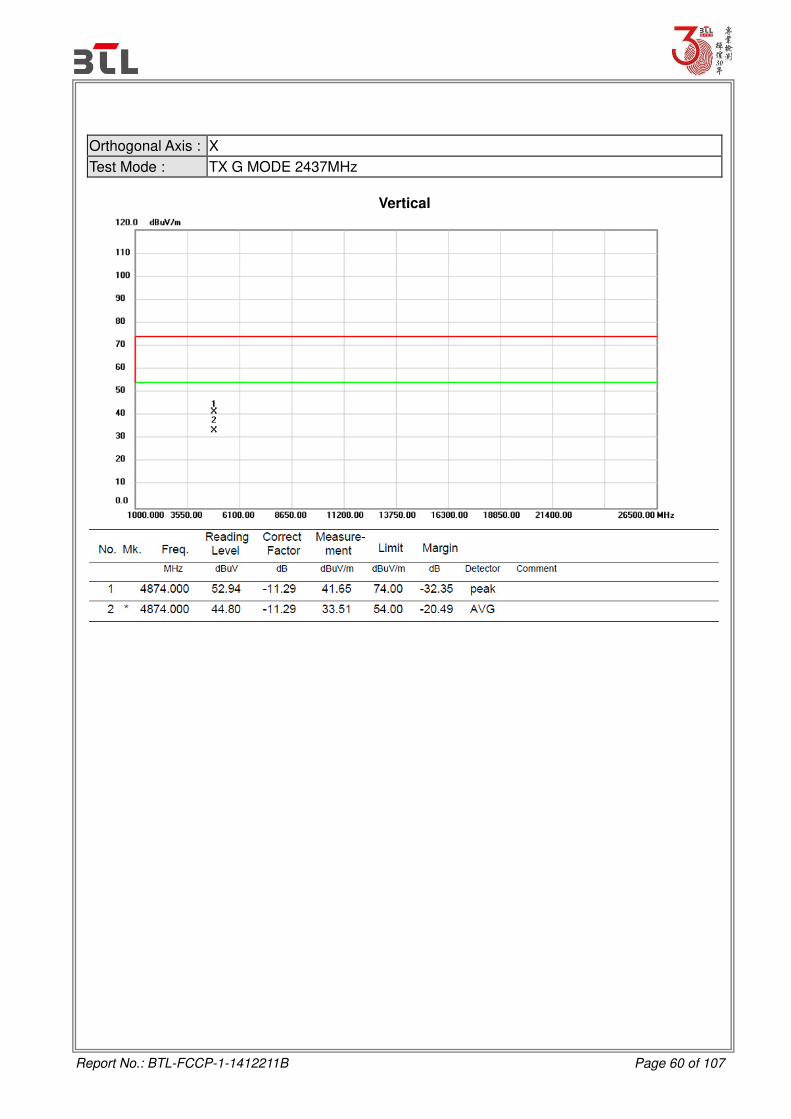
Orthogonal Axis : X
Test Mode : TX G MODE 2437MHz
Vertical

Report No.: BTL-FCCP-1-1412211B Page 61 of 107
Orthogonal Axis : X
Test Mode : TX G MODE 2437MHz
Horizontal

Report No.: BTL-FCCP-1-1412211B Page 62 of 107
Orthogonal Axis : X
Test Mode : TX G MODE 2437MHz
Horizontal

Report No.: BTL-FCCP-1-1412211B Page 63 of 107
Orthogonal Axis : X
Test Mode : TX G MODE 2462MHz
Vertical

Report No.: BTL-FCCP-1-1412211B Page 64 of 107
Orthogonal Axis : X
Test Mode : TX G MODE 2462MHz
Vertical

Report No.: BTL-FCCP-1-1412211B Page 65 of 107
Orthogonal Axis : X
Test Mode : TX G MODE 2462MHz
Horizontal

Report No.: BTL-FCCP-1-1412211B Page 66 of 107
Orthogonal Axis : X
Test Mode : TX G MODE 2462MHz
Horizontal

Report No.: BTL-FCCP-1-1412211B Page 67 of 107
Orthogonal Axis : X
Test Mode : TX N-20M MODE 2412MHz
Vertical

Report No.: BTL-FCCP-1-1412211B Page 68 of 107
Orthogonal Axis : X
Test Mode : TX N-20M MODE 2412MHz
Vertical

Report No.: BTL-FCCP-1-1412211B Page 69 of 107
Orthogonal Axis : X
Test Mode : TX N-20M MODE 2412MHz
Horizontal

Report No.: BTL-FCCP-1-1412211B Page 70 of 107
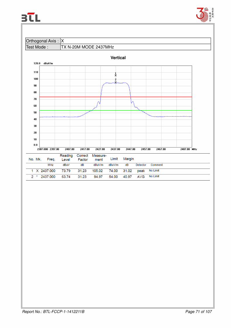
Orthogonal Axis : X
Test Mode : TX N-20M MODE 2412MHz
Horizontal
Report No.: BTL-FCCP-1-1412211B Page 71 of 107
Orthogonal Axis : X
Test Mode : TX N-20M MODE 2437MHz
Vertical

Report No.: BTL-FCCP-1-1412211B Page 72 of 107
Orthogonal Axis : X
Test Mode : TX N-20M MODE 2437MHz
Vertical
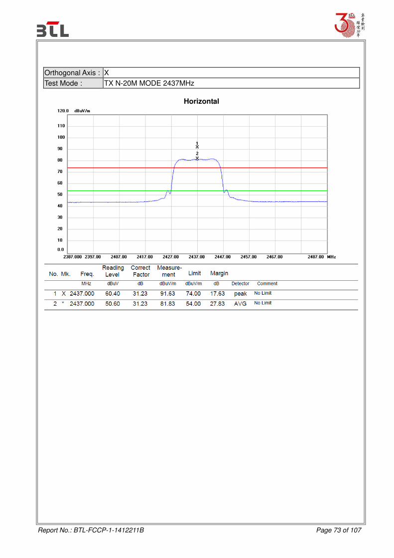
Report No.: BTL-FCCP-1-1412211B Page 73 of 107
Orthogonal Axis : X
Test Mode : TX N-20M MODE 2437MHz
Horizontal

Report No.: BTL-FCCP-1-1412211B Page 74 of 107
Orthogonal Axis : X
Test Mode : TX N-20M MODE 2437MHz
Horizontal

Report No.: BTL-FCCP-1-1412211B Page 75 of 107
Orthogonal Axis : X
Test Mode : TX N-20M MODE 2462MHz
Vertical

Report No.: BTL-FCCP-1-1412211B Page 76 of 107
Orthogonal Axis : X
Test Mode : TX N-20M MODE 2462MHz
Vertical

Report No.: BTL-FCCP-1-1412211B Page 77 of 107
Orthogonal Axis : X
Test Mode : TX N-20M MODE 2462MHz
Horizontal

Report No.: BTL-FCCP-1-1412211B Page 78 of 107
Orthogonal Axis : X
Test Mode : TX N-20M MODE 2462MHz
Horizontal

Report No.: BTL-FCCP-1-1412211B Page 79 of 107
ATTACHMENT E - BANDWIDTH

Report No.: BTL-FCCP-1-1412211B Page 80 of 107
Test Mode : TX B Mode_CH01/06/11
TX CH01

Report No.: BTL-FCCP-1-1412211B Page 81 of 107
TX CH06
TX CH11

Report No.: BTL-FCCP-1-1412211B Page 82 of 107
Test Mode: TX G Mode_CH01/06/11
TX CH01

Report No.: BTL-FCCP-1-1412211B Page 83 of 107
TX CH06
TX CH11

Report No.: BTL-FCCP-1-1412211B Page 84 of 107
Test Mode : TX N-20MHz Mode_CH01/06/11
TX CH01

Report No.: BTL-FCCP-1-1412211B Page 85 of 107
TX CH06
TX CH11

Report No.: BTL-FCCP-1-1412211B Page 86 of 107
ATTACHMENT F – MAXIMUM PEAK CONDUCTED OUTPUT POWER
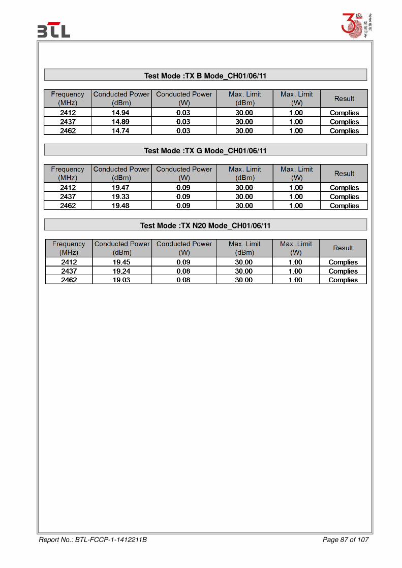
Report No.: BTL-FCCP-1-1412211B Page 87 of 107
Test Mode :TX B Mode_CH01/06/11
Test Mode :TX G Mode_CH01/06/11
Test Mode :TX N20 Mode_CH01/06/11
Report No.: BTL-FCCP-1-1412211B Page 88 of 107
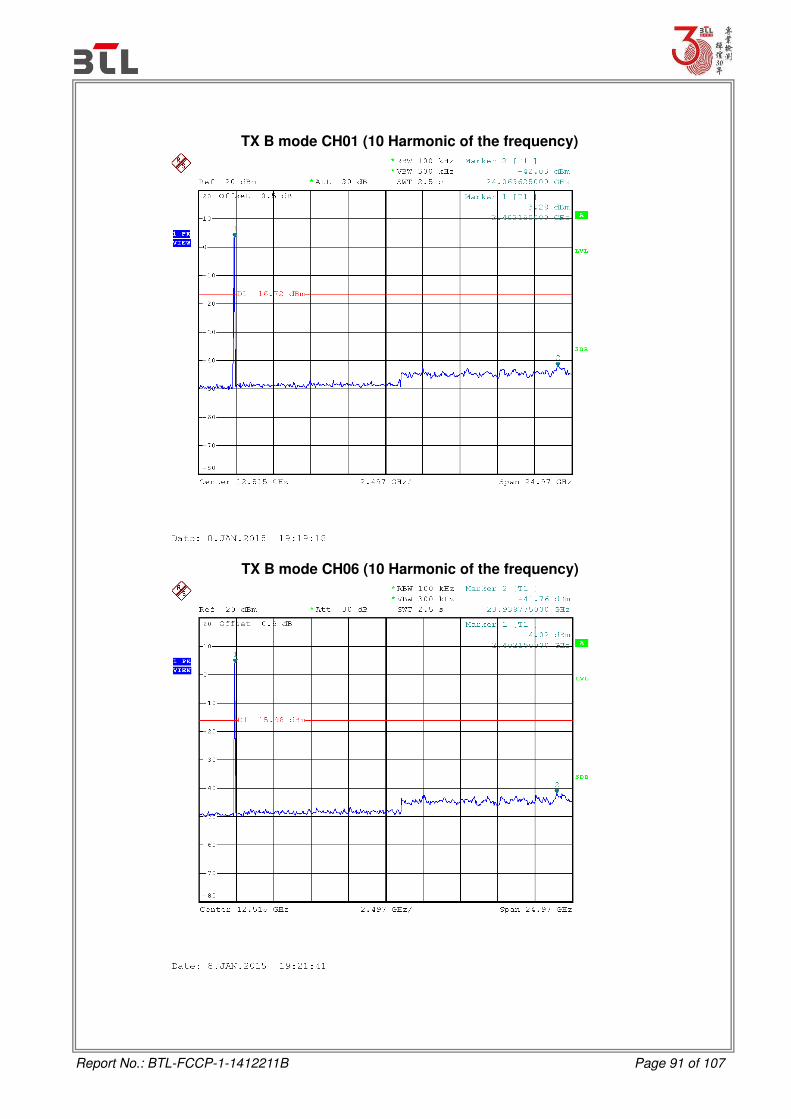
ATTACHMENT G - ANTENNA CONDUCTED SPURIOUS EMISSION

Report No.: BTL-FCCP-1-1412211B Page 89 of 107
Test Mode : TX B Mode
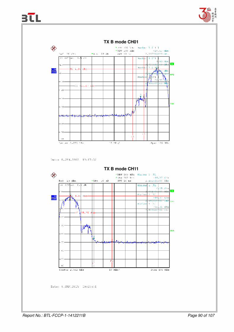
Report No.: BTL-FCCP-1-1412211B Page 90 of 107
TX B mode CH01
TX B mode CH11
Report No.: BTL-FCCP-1-1412211B Page 91 of 107
TX B mode CH01 (10 Harmonic of the frequency)
TX B mode CH06 (10 Harmonic of the frequency)

Report No.: BTL-FCCP-1-1412211B Page 92 of 107
TX B mode CH11 (10 Harmonic of the frequency)

Report No.: BTL-FCCP-1-1412211B Page 93 of 107
Test Mode : TX G Mode

Report No.: BTL-FCCP-1-1412211B Page 94 of 107
TX G mode CH01
TX G mode CH11

Report No.: BTL-FCCP-1-1412211B Page 95 of 107
TX G mode CH01 (10 Harmonic of the frequency)
TX G mode CH06 (10 Harmonic of the frequency)

Report No.: BTL-FCCP-1-1412211B Page 96 of 107
TX G mode CH11 (10 Harmonic of the frequency)

Report No.: BTL-FCCP-1-1412211B Page 97 of 107
Test Mode : TX N-20M Mode

Report No.: BTL-FCCP-1-1412211B Page 98 of 107
TX HT20 mode CH01
TX HT20 mode CH11

Report No.: BTL-FCCP-1-1412211B Page 99 of 107
TX HT20 mode CH01 (10 Harmonic of the frequency)
TX HT20 mode CH06 (10 Harmonic of the frequency)

Report No.: BTL-FCCP-1-1412211B Page 100 of 107
TX HT20 mode CH11 (10 Harmonic of the frequency)

Report No.: BTL-FCCP-1-1412211B Page 101 of 107
ATTACHMENT H - POWER SPECTRAL DENSITY
Report No.: BTL-FCCP-1-1412211B Page 102 of 107
Test Mode :TX B Mode_CH01/06/11
TX CH01
Report No.: BTL-FCCP-1-1412211B Page 103 of 107
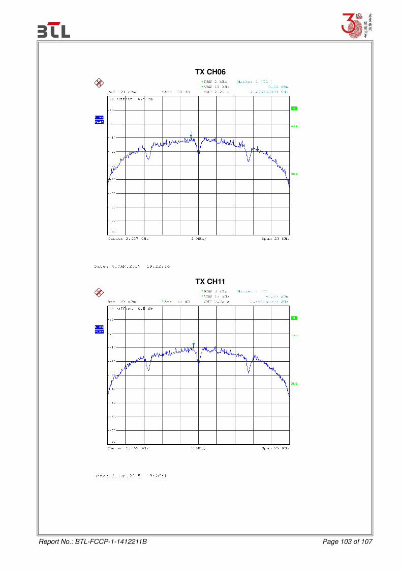
TX CH06
TX CH11

Report No.: BTL-FCCP-1-1412211B Page 104 of 107
Test Mode :TX G Mode_CH01/06/11
TX CH01

Report No.: BTL-FCCP-1-1412211B Page 105 of 107
TX CH06
TX CH11
Report No.: BTL-FCCP-1-1412211B Page 106 of 107
Test Mode : TX N-20M Mode_CH01/06/11
TX CH01

Report No.: BTL-FCCP-1-1412211B Page 107 of 107
TX CH06
TX CH11