Fatigue investigations on steel pipeline containing 3D ...
15
This document is downloaded from DR‑NTU (https://dr.ntu.edu.sg) Nanyang Technological University, Singapore. Fatigue investigations on steel pipeline containing 3D coplanar and non‑coplanar cracks Xiao, Zhongmin; Zhang, Wengang; Zhang, Yanmei; Fan, Mu 2020 Xiao, Z., Zhang, W., Zhang, Y. & Fan, M. (2020). Fatigue investigations on steel pipeline containing 3D coplanar and non‑coplanar cracks. Computers, Materials and Continua, 62(1), 267‑280. https://dx.doi.org/10.32604/cmc.2020.06567 https://hdl.handle.net/10356/146881 https://doi.org/10.32604/cmc.2020.06567 © 2020 The Author(s). This work is licensed under a Creative Commons Attribution 4.0 International License , which permits unrestricted use, distribution, and reproduction in any medium, provided the original work is properly cited. Downloaded on 26 Mar 2022 19:22:13 SGT
Transcript of Fatigue investigations on steel pipeline containing 3D ...

This document is downloaded from DR‑NTU (https://dr.ntu.edu.sg)Nanyang Technological University, Singapore.
Fatigue investigations on steel pipelinecontaining 3D coplanar and non‑coplanar cracks
Xiao, Zhongmin; Zhang, Wengang; Zhang, Yanmei; Fan, Mu
2020
Xiao, Z., Zhang, W., Zhang, Y. & Fan, M. (2020). Fatigue investigations on steel pipelinecontaining 3D coplanar and non‑coplanar cracks. Computers, Materials and Continua,62(1), 267‑280. https://dx.doi.org/10.32604/cmc.2020.06567
https://hdl.handle.net/10356/146881
https://doi.org/10.32604/cmc.2020.06567
© 2020 The Author(s). This work is licensed under a Creative Commons Attribution 4.0International License , which permits unrestricted use, distribution, and reproduction inany medium, provided the original work is properly cited.
Downloaded on 26 Mar 2022 19:22:13 SGT

Computers, Materials & Continua CMC, vol.62, no.1, pp.267-280, 2020
CMC. doi:10.32604/cmc.2020.06567 www.techscience.com/cmc
Fatigue Investigations on Steel Pipeline Containing 3D Coplanar and Non-Coplanar Cracks
Zhongmin Xiao1, Wengang Zhang2, Yanmei Zhang1, * and Mu Fan3
Abstract: Fluctuated loadings from currents, waves and sea ground motions are observed on offshore steel pipelines, and they will result in small cracks to propagate continuously and cause unexpected damage to offshore/geotechnical infrastructures. In spite of the availability of efficient techniques and high-power computers for solving crack problems, investigations on the fatigue life of offshore pipelines with 3D interacting cracks are still rarely found in open literature. In the current study, systematic numerical investigations are performed on fatigue crack growth behaviours of offshore pipelines containing coplanar and non-coplanar cracks. Extended finite element method (XFEM) is adopted to simulate the fatigue crack growth. The qualitative validations of numerical results are made for certain cases with available experimental results. Parametric studies are conducted to investigate the influences of various important parameters on fatigue crack growth. The results will be helpful to assess the fatigue behaviours of steel pipeline with 3D interacting cracks. Keywords: Fatigue crack growth, steel pipeline, coplanar cracks, non-coplanar cracks, XFEM.
1 Introduction Multiple cracks are often observed in various cases of aging engineering structures such as pressure vessels and pipelines. The coalescence and interaction of multiple cracks pose a significant challenge to the integrity of the structures, and lead to various types of fracture failures, such as stress corrosion cracking, fatigue and corrosion fatigue [Soboyejo, Knottm, Walsh et al. (1990); Wang, Atkinson, Akid et al. (1996); Fang, Eslami, Kania et al. (2009); Luo and Wang (2009); Luo, Li and Xiao (2014); Zhao, Zhu and Luo (2016)]. Based on the existing standard and codes like ASME [ASME (2013)] and BS7910 (BSI 2005), those multiple small cracks are treated as an equivalent single large one through a certain combination rules. However, when the distance between any two adjacent cracks decreases, the interaction between these two cracks becomes increasingly significant and considerably affects the cracks’ fracture behaviour. A
1 School of Mechanical and Aerospace Engineering, Nanyang Technological University, 639798, Singapore. 2 School of Civil Engineering, Chongqing University, Chongqing, 400045, China. 3 College of Aerospace Engineering, Nanjing University of Aeronautics & Astronautics, Nanjing, 210016, China. * Corresponding Authors: Yanmei Zhang. Email: [email protected];
Wengang Zhang. Email: [email protected].

268 CMC, vol.62, no.1, pp.267-280, 2020
simplified procedure produces unreliable and over-conservative predictions of the cracked component’s fatigue life [Frise and Bell (1992); Zhang, Ariffin, Xiao et al. (2015)]. Therefore, a reasonable and accurate approach is deemed desirable to evaluate the fatigue behaviours of multiple cracks. For the fatigue analysis, the crack growth can be predicted by the established empirical relationship between the crack extension and stress intensity factor [Anderson (2005)]. Meanwhile, a large volume of the research work has been put on the crack growth modelling. For instance, the cracking particle method was proposed to simulate the crack growth and crack branching by dividing the crack into many particles [Rabczuk and Belytschko (2004, 2007); Rabczuk, Zi, Bordas et al. (2010)]. Another theoretical analysis of the crack growth is dual-horizon peridynamics technique [Areias, Rabczuk and Dias-da-Costa (2013); Areias, Msekh and Rabczuk (2016); Areias, Msekh and Rabczuk (2016); Ren, Zhuang, Cai et al. (2016); Areias and Rabczuk (2017); Ren, Zhuang and Rabczuk (2017); Areias, Reinoso, Camanho et al. (2018)], which was used to analyze the crack pattern of random point distribution and applicable for the multiple materials issue in peridynamics. These two numerical models are only suitable for the small computational domain and simple 3D geometric structures. The phase-field model (PFM) was proposed recently to model the crack propagation, which could be coupled into COMSOL to be solved as a whole system [Zhou, Rabczuk and Zhuang (2018); Zhou, Zhuang and Rabczuk (2018); Zhou, Zhuang, Zhu et al. (2018)]. In addition, the extended finite element method (XFEM) was proposed to solve the computational difficulties in crack growth [Moës, Dolbow and Belytschko (1999); Dolbow, Moës and Belytschko (2000)]. In XFEM, a discontinuous (jump) function and the near-tip asymptotic functions are introduced and incorporated into the finite element approximation [Dolbow, Moës and Belytschko (2000); Khoei (2015)]. XFEM is adopted in this study since it is able to characterize crack extension freely in finite element methods without re-meshing as well as to simulate the fatigue process of the complicated structures. Recently, taking the interaction of multiple cracks into account, many researches presented the fatigue assessment procedures of the multiple cracks using the revised stress intensity factor [Kamaya (2008b); Konosu and Kasahara (2012); Surendran, Palani and Nagesh (2012); Kotousov and Chang (2015); Zhang, Fan and Xiao (2016); Ji, Robert, Zhang et al. (2017)]. With this approach, the interaction factor of multiple cracks was defined through the crack parameters [Moussa, Bell and Tan (1999)]. Based on the interaction of multiple cracks and modified stress intensity factor, a failure assessment diagram was proposed for multiple surface flaws subject to limited loadings [Konosu and Kasahara (2012); Zhang, Ariffin, Xiao et al. (2015)]. In this paper, a systematic study is carried out to investigate the fatigue crack initiation and fatigue crack growth rate of steel pipeline containing interacting cracks. With respect to the cracks position, the coplanar and non-coplanar cracks are considered to simulate the practical scenarios. As the surface cracks tend to be semi-elliptical under normal loadings [Mahmoud (1988); Lin and Smith (1999)], the semi-elliptical surface crack and elliptical embedded crack are adopted for the interacting cracks. The qualitative validations of the numerical results are made for certain cases with available experimental results. Considering of the significance of the parameter sensitivity in the computational analysis

Fatigue Investigations on Steel Pipeline Containing 3D Coplanar 269
[Vu-Bac, Lahmer, Zhuang et al. (2016); Hamdia, Silani, Zhuang et al. (2017); Hamdia, Ghasemi, Zhuang et al. (2018)], parametric studies are conducted for the geometrical configuration of the interacting cracks. The discussion on the effects of the important parameters on the fatigue behaivours is given based on the parametric studies.
2 Numerical model 2.1 Multiple crack configuration in steel pipeline 3D FE simulations are conducted for circumferentially flawed pipeline with multiple cracks. The outer diameter D and the wall thickness t are taken to be 400 mm and 18 mm, respectively. Since the fatigue tension loading is applied on the pipeline and the interacting cracks are located in the center section of the pipeline, the length of the pipeline L used in all simulations is two times of the outer diameter. It is a compromise value that will promote the simulation and not induce a significant discrepancy on the computational results. Two 3D interacting cracks are considered in this study: one is a semi-elliptical external surface crack and the other one is an elliptical embedded crack in the section profile of pipeline, illustrated in Fig. 1(a). For the ease of discussion, the cracks configuration along the wall thickness is presented in Fig. 1(b). As shown, the separation distance in the radial direction is denoted by X, and the vertical distance is denoted by Y. According to the studies made by Konosu et al. [Konosu and Kasahara (2012)], the maximum value of normalized separation distance for 𝑋𝑋
2𝑎𝑎 and 𝑌𝑌
2𝑎𝑎 is 0.2, which accounts for a considerable
cracks interaction. Considering that, a crack size of 𝑎𝑎=3.5 mm and a separation distance of 𝑋𝑋=2 mm Y=1 mm is used as the nominal values. Two variations of X are 1 mm and 3 mm due to the limited wall thickness, while the other values of Y are taken as 0 and 2 mm. It should be noted that if Y is equal to 0 mm, it becomes the coplanar cracks problem.
(a) (b)
(c)
Figure 1: (a) Side view of the two interacting cracks, (b) Non-coplanar cracks configuration along the wall thickness t and (c) Notations of the crack tips
270 CMC, vol.62, no.1, pp.267-280, 2020
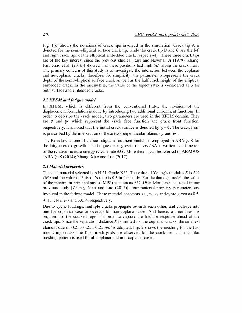
Fig. 1(c) shows the notations of crack tips involved in the simulation. Crack tip A is denoted for the semi-elliptical surface crack tip, while the crack tip B and C are the left and right crack tips of the elliptical embedded crack, respectively. These three crack tips are of the key interest since the previous studies [Raju and Newman Jr (1979); Zhang, Fan, Xiao et al. (2016)] showed that these positions had high SIF along the crack front. The primary concern of this study is to investigate the interaction between the coplanar and no-coplanar cracks, therefore, for simplicity, the parameter a represents the crack depth of the semi-elliptical surface crack as well as the half crack height of the elliptical embedded crack. In the meanwhile, the value of the aspect ratio is considered as 3 for both surface and embedded cracks.
2.2 XFEM and fatigue model In XFEM, which is different from the conventional FEM, the revision of the displacement formulation is done by introducing two additional enrichment functions. In order to describe the crack model, two parameters are used in the XFEM domain. They are ϕ and ψ which represent the crack face function and crack front function, respectively. It is noted that the initial crack surface is denoted by 0ϕ = . The crack front is prescribed by the intersection of these two perpendicular planes -ϕ and ψ . The Paris law as one of classic fatigue assessment models is employed in ABAQUS for the fatigue crack growth. The fatigue crack growth rate /da dN is written as a function of the relative fracture energy release rate G∆ . More details can be referred to ABAQUS [ABAQUS (2014); Zhang, Xiao and Luo (2017)].
2.3 Material properties The steel material selected is API 5L Grade X65. The value of Young’s modulus E is 209 GPa and the value of Poisson’s ratio is 0.3 in this study. For the damage model, the value of the maximum principal stress (MPS) is taken as 667 MPa. Moreover, as stated in our previous study [Zhang, Xiao and Luo (2017)], four material-property parameters are involved in the fatigue model. These material constants 1c , 2c , 3c and 4c are given as 0.5, -0.1, 1.1421e-7 and 3.034, respectively. Due to cyclic loadings, multiple cracks propagate towards each other, and coalesce into one for coplanar case or overlap for non-coplanar case. And hence, a finer mesh is required for the cracked region in order to capture the fracture response ahead of the crack tips. Since the separation distance X is limited for the coplanar cracks, the smallest element size of 30.25 0.25 0.25mm× × is adopted. Fig. 2 shows the meshing for the two interacting cracks, the finer mesh grids are observed for the crack front. The similar meshing pattern is used for all coplanar and non-coplanar cases.

Fatigue Investigations on Steel Pipeline Containing 3D Coplanar 271
Figure 2: Typical meshing for the two interacting cracks with smallest element size
Since the high cyclic fatigue analysis is performed in this study, only the elastic stress range is considered for the cyclic loadings. Consequently, the maximum tension load is taken as 250 MPa. To distinguish the different cyclic loading ranges, two values of the stress ratio min max/R σ σ= are 0.1 and 0.5 used in our investigation, where σmin and σmax are the minimum and the maximum tension applied, respectively. The setup of boundary conditions and loading can be referred to our previous work [Zhang, Xiao and Luo (2017)].
3 Results and discussion 3.1 Validations with available experimental studies 3.1.1 Fatigue crack growth of two coplanar cracks Fig. 3 shows the scenarios of the crack front progress in PSILSM mode at the corresponding loading cycles after the two coplanar cracks coalesced. The level set contour plot of PSILSM represents the crack front. The crack growth is denoted by the red colour.
2.4 × 10⁵ cycles 2.6 × 10⁵ cycles 2.8 × 10⁵ cycles
Figure 3: Crack propagations of two coplanar cracks in the re-entrant region for X=2 mm

272 CMC, vol.62, no.1, pp.267-280, 2020
It is observed in this figure that the two coplanar cracks coalesce at 52.4 10× cycles. The cyclic loading is still applied on the steel pipeline. When it is at 52.8 10× cycles, the crack growth length in the re-entrant region reaches up to 6 mm, around 3 times the separation distance X (X=2 mm). It illustrates that a relatively fast crack growth rate is observed after the two cracks’ coalescence. This similar trend is found in the other simulation runs for the two coplanar cracks. The observation in crack growth rate is consistent with the experimental result [Kamaya (2008a)] where it stated that there was an expedited crack growth rate in the re-entrant section.
3.1.2 Fatigue crack growth of two non-coplanar cracks The two non-coplanar cracks exhibit a different fatigue behavior, compared with the coplanar cracks. Due to the cracks interaction, the inner crack tips propagate towards each other and the outer crack tips propagate outwards straightly.
(a)
(b)
Figure 4: Crack propagation profiles of the two non-coplanar cracks at (a) Y=1 mm and (b) Y=2 mm The similar fatigue crack growth trend is observed in all the non-coplanar simulations. Fig. 4 shows two typical crack propagation profiles at Y=1 mm and Y=2 mm, respectively. The initial crack size is denoted by the bold black line. The curved black lines represent the crack propagation path during simulation. It is obvious that crack tip A propagates slightly upwards and crack tip B propagates downwards close to crack tip A. Moreover, due to the strong crack interaction, the crack propagation rate at crack tip A and B is faster than that at crack tip C.

Fatigue Investigations on Steel Pipeline Containing 3D Coplanar 273
(a) (b)
Figure 5: Crack profiles of the embedded crack by the plot of PSILSM: (a) At 6 × 10⁵ cycles for Y=1 mm and (b) At 5× 10⁵ cycles for Y=2 mm
Furthermore, it is found that the crack front of the semi-elliptical crack is distorted during the crack propagation, due to the cracks interaction. Two examples from the non-coplanar cases are presented in Fig. 5 which shows the crack profiles of the embedded crack for Y=1 mm and Y=2 mm, respectively. First of all, a large amount of crack extension is observed along the crack height direction, while little crack extension takes place along the crack length direction. Second observation is that the crack tip B propagates faster than crack tip C, as expected. Lastly, it is noticed that at crack tip B, the propagation appears to stop around the midsection between the surface and the embedded crack. As for crack tip C, it is propagating normally. All the observations are in good agreement with Kamaya’s experimental results [Kamaya (2008a)]. It demonstrates that our numerical simulation results are logic and reasonable, and our investigation can produce reliable results in predicting the fatigue propagations of interacting cracks.
3.2 Parametric studies on fatigue crack growth behaviours Many research studies on the stress intensity factor along the crack front of two interacting cracks show that there is a strong dependency on the relative crack positions [Soboyejo, Knottm, Walsh et al. (1990); Saxena (2011); Konosu and Kasahara (2012); Singh, Mishra and Bhattacharya (2012)]. In our current study, three sets of simulation runs are conducted to investigate the fatigue behaviours by varying the two cracks’ relative positions in the thickness X and vertical Y direction and the stress ratio R. They are listed in Tab. 1.
Table 1: Values of each parameters used in parametric study
Parameter Value
X (mm) 1, 2, 3
Y (mm) 0, 1, 2
R 0.1, 0.5

274 CMC, vol.62, no.1, pp.267-280, 2020
3.2.1 Varying crack positions The variations of crack extension with the number of cycles at three crack tips are given in Fig. 6 and Fig. 7 for Y=0 mm and Y=2 mm, respectively. In the both figures, all plots show that the closer the two cracks in X direction, the faster the crack initiation and propagation.
(a) (b)
(c)
Figure 6: Crack extensions for different X values at (a) crack tip A, (b) crack tip B and (c) crack tip C, when Y=0 mm is considered
Both crack tip A and crack tip B in Fig. 6 display a similar trend in propagation rate for X=2 mm and X=3 mm, indicating that they have close interaction factor values. At X=1 mm, i.e., the two cracks are very near each other, the interaction factor is considerably higher than the others, resulting in much faster crack propagation. As for crack tip C, the results from X=2 mm and X=3 mm show almost the same propagation curves. It is noted that there is no result for X=1 mm due to the fast coalescence of crack tip A and B. It indicates that the variation of X separation distance has little influence on the crack behaviors of crack tip C when the coplanar cracks are considered.

Fatigue Investigations on Steel Pipeline Containing 3D Coplanar 275
(a) (b)
(c)
Figure 7: Crack extensions for different X values at (a) crack tip A, (b) crack tip B and (c) crack tip C, when Y=2 mm is considered
The crack propagations at crack tip A and B increase gradually with the decreasing X separation distance, for the case of non-coplanar cracks with Y=2 mm as shown in Fig. 7. The curves for X=1 mm and X=2 mm are closer compared with the curve of X=3 mm which has a smaller crack propagation rate. However, at crack tip C, the number of cycles for crack initiation are nearly the same for the three different X values. For the crack propagation at crack tip C, the curve of X=1 mm has a relatively higher propagation rate than the other two.
3.2.2 Varying crack positions To further study the effect of the vertical separation distance Y values on the fatigue crack growth behaviours, the crack tip separation distance X (the horizontal distance between crack tip A and B) with the number of cycles are plotted for three different Y values in Fig. 8. The result with the initial value X=2 mm is presented in Fig. 8(a). It should be noted that for Y=0 mm, i.e., for the two coplanar cracks case, the curve stops at X=0 mm when the two cracks coalesced. For Y=1 and 2 mm, the X value can be negative as the two non-coplanar cracks are not merging together (but overlapping for top view). At the

276 CMC, vol.62, no.1, pp.267-280, 2020
beginning stage, the crack propagation of the two coplanar cracks is slower than the non-coplanar cases. Only when the cracks are going to coalesce, the propagation rate becomes higher than the other two cases. Nevertheless, the two curves of the non-coplanar cases are close to each other before the crack extension reaches 1.5 mm, indicating that they have a similar propagation rate at this stage for Y=1 mm and Y=2 mm. After that, the case of Y=1 mm has a higher propagation rate, compared with the case of Y=2 mm. Fig. 8(b) shows the results of the initial value X=3 mm for different Y values. Before the two cracks overlap, i.e., X>0, the case of Y=2 mm has the highest propagation rate, while the smallest propagation rate is observed for the case of Y=0 mm (coplanar cracks case). However, for X<0, two non-coplanar cracks in the case of Y=2 mm propagate slower than that in the case of Y=1 mm.
(a) (b)
Figure 8: Variation of the X value with the number of cycles for different Y values at (a) The initial value X=2 mm and (b) The initial value X=3 mm
From the results of the current subsection, it is observed that at various Y values, when the two cracks are getting closer, it does not necessarily result in faster crack propagation. One study [Konosu and Kasahara (2012)] on the multiple cracks interaction factor found that the peak of interaction factor does not locate at the Y=0 mm when plotted with varying Y value. The further the cracks in separation distance-X, the peak interaction factor is located at a higher separation distance Y. Moreover, it was also observed from [ Surendran, Palani and Nagesh (2012)] that the peak position of the interaction factor shifted further away from Y=0 mm as the X value increases. All these studies could explain why the case of Y=2 mm has a slightly higher propagation rate before the two non-coplanar cracks’ overlapping from our current results shown. Overall, the fatigue crack growth results obtained in this study are in good agreement with other research works on multiple cracks.
3.2.3 Effect of stress ratio Two values of the stress ratios R=0.1 and R=0.5 are considered for comparisons. Fig. 9 presents the crack extensions of the interacting crack tips under these two stress ratio conditions. As for the two coplanar cracks shown in Fig. 9(a), it is observed that by increasing the stress ratio from 0.1 to 0.5, the number of cycles required is nearly doubled for the same amount of propagation at both crack tip A and B. The similar trend is also
Fatigue Investigations on Steel Pipeline Containing 3D Coplanar 277
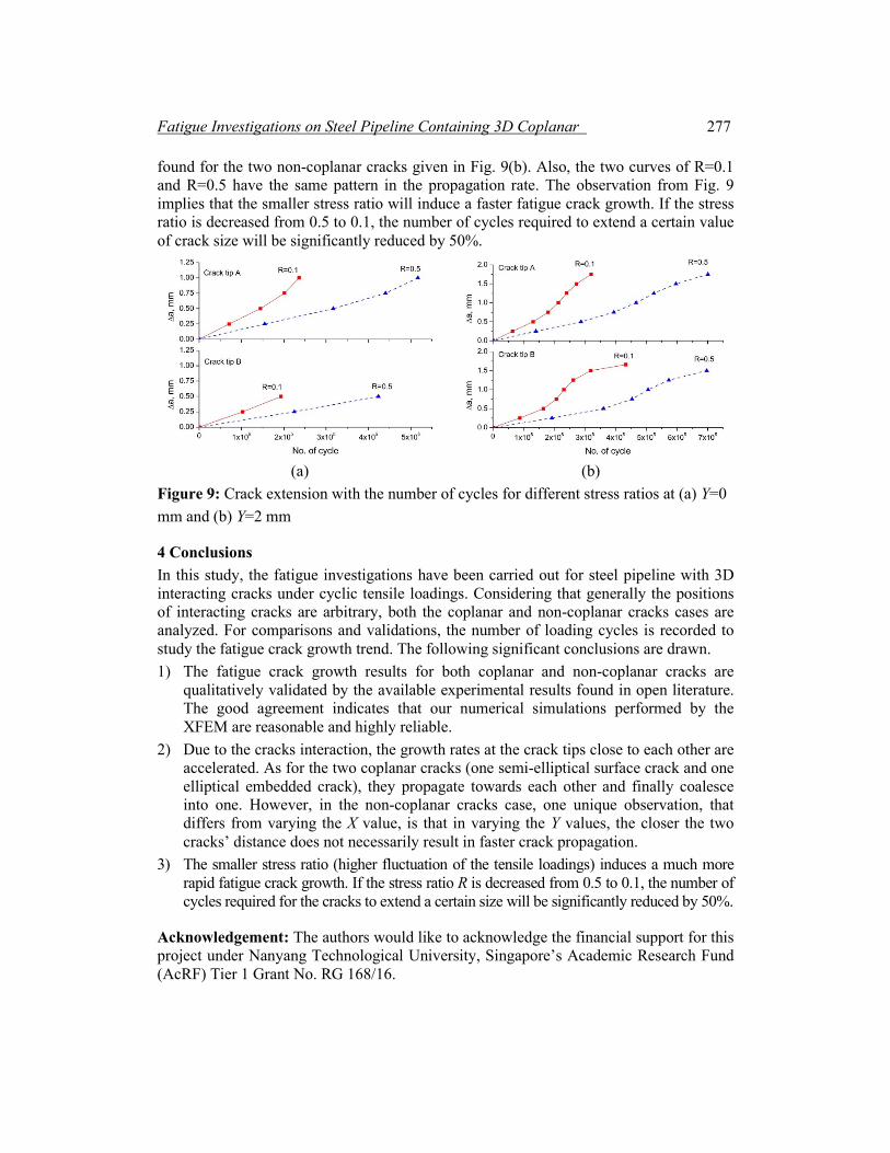
found for the two non-coplanar cracks given in Fig. 9(b). Also, the two curves of R=0.1 and R=0.5 have the same pattern in the propagation rate. The observation from Fig. 9 implies that the smaller stress ratio will induce a faster fatigue crack growth. If the stress ratio is decreased from 0.5 to 0.1, the number of cycles required to extend a certain value of crack size will be significantly reduced by 50%.
(a) (b)
Figure 9: Crack extension with the number of cycles for different stress ratios at (a) Y=0 mm and (b) Y=2 mm
4 Conclusions In this study, the fatigue investigations have been carried out for steel pipeline with 3D interacting cracks under cyclic tensile loadings. Considering that generally the positions of interacting cracks are arbitrary, both the coplanar and non-coplanar cracks cases are analyzed. For comparisons and validations, the number of loading cycles is recorded to study the fatigue crack growth trend. The following significant conclusions are drawn. 1) The fatigue crack growth results for both coplanar and non-coplanar cracks are
qualitatively validated by the available experimental results found in open literature. The good agreement indicates that our numerical simulations performed by the XFEM are reasonable and highly reliable.
2) Due to the cracks interaction, the growth rates at the crack tips close to each other are accelerated. As for the two coplanar cracks (one semi-elliptical surface crack and one elliptical embedded crack), they propagate towards each other and finally coalesce into one. However, in the non-coplanar cracks case, one unique observation, that differs from varying the X value, is that in varying the Y values, the closer the two cracks’ distance does not necessarily result in faster crack propagation.
3) The smaller stress ratio (higher fluctuation of the tensile loadings) induces a much more rapid fatigue crack growth. If the stress ratio R is decreased from 0.5 to 0.1, the number of cycles required for the cracks to extend a certain size will be significantly reduced by 50%.
Acknowledgement: The authors would like to acknowledge the financial support for this project under Nanyang Technological University, Singapore’s Academic Research Fund (AcRF) Tier 1 Grant No. RG 168/16.

278 CMC, vol.62, no.1, pp.267-280, 2020
References ABAQUS (2014): ABAQUS Documentation. RI, USA.: Dassault Systèmes. Anderson, T. L. (2005): Fracture Mechanics: Fundamentals and Applications, 3rd Ed. Florida, USA: CRC Press Taylor & Francis Group. Areias, P.; Msekh, M. A.; Rabczuk, T. (2016): Damage and fracture algorithm using the screened Poisson equation and local remeshing. Engineering Fracture Mechanics, vol. 158, pp. 116-143. Areias, P.; Rabczuk, T. (2017): Steiner-point free edge cutting of tetrahedral meshes with applications in fracture. Finite Elements in Analysis and Design, vol. 132, pp. 27-41. Areias, P.; Rabczuk, T.; Dias-da-Costa, D. (2013): Element-wise fracture algorithm based on rotation of edges. Engineering Fracture Mechanics, vol. 110, pp. 113-137. Areias, P.; Rabczuk, T.; Msekh, M. A. (2016): Phase-field analysis of finite-strain plates and shells including element subdivision. Computer Methods in Applied Mechanics and Engineering, vol. 312, pp. 322-350. Areias, P.; Reinoso, J.; Camanho, P. P.; César de Sá, J.; Rabczuk, T. (2018): Effective 2D and 3D crack propagation with local mesh refinement and the screened poisson equation. Engineering Fracture Mechanics, vol. 189, pp. 339-360. ASME (2013): Boiler and Pressure Vessel Code. Philadelphia, PA: American Society of Mechanical Engineers. BSI (2005): Guide to Methods for Assessing the Acceptability of Flaws in Metallic Structures. London: British Standards Institution. Dolbow, J.; Moës, N.; Belytschko, T. (2000): Discontinuous enrichment in finite elements with a partition of unity method. Finite Elements in Analysis and Design, vol. 36, no. 3, pp. 235-260. Fang, B. Y.; Eslami, A.; Kania, R.; Worthingham, R. (2009): Stress corrosion crack initiation in X-65 pipeline steel under disbonded coating with cathodic protection. Proceedings of the Biennial International Pipeline Conference. Frise, P. R.; Bell, R. (1992): Modelling fatigue crack growth and coalescence in notches. International Journal of Pressure Vessels and Piping, vol. 51, no. 1, pp. 107-126. Hamdia, K. M.; Ghasemi, H.; Zhuang, X.; Alajlan, N.; Rabczuk, T. (2018): Sensitivity and uncertainty analysis for flexoelectric nanostructures. Computer Methods in Applied Mechanics and Engineering, vol. 337, pp. 95-109. Hamdia, K. M.; Silani, M.; Zhuang, X.; He, P.; Rabczuk, T. (2017): Stochastic analysis of the fracture toughness of polymeric nanoparticle composites using polynomial chaos expansions. International Journal of Fracture, vol. 206, no. 2, pp. 215-227. Ji, J.; Robert, D. J.; Zhang, C.; Zhang, D.; Kodikara, J. (2017): Probabilistic physical modelling of corroded cast iron pipes for lifetime prediction. Structural Safety, vol. 64, pp. 62-75. Kamaya, M. (2008a): Growth evaluation of multiple interacting surface cracks. Part I: Experiments and simulation of coalesced crack. Engineering Fracture Mechanics, vol. 75, no. 6, pp. 1336-1349.

Fatigue Investigations on Steel Pipeline Containing 3D Coplanar 279
Kamaya, M. (2008b): Growth evaluation of multiple interacting surface cracks. Part II: Growth evaluation of parallel cracks. Engineering Fracture Mechanics, vol. 75, no. 6, pp. 1350-1366. Khoei, A. R. (2015): Extended finite element method: theory and applications. (extended finite element method: theory and applications. Computational/Numerical Methods. Konosu, S.; Kasahara, K. (2012): Multiple fatigue crack growth prediction using stress intensity factor solutions modified by empirical interaction factors. Journal of Pressure Vessel Technology, Transactions of the ASME, vol. 134, no. 1. Kotousov, A.; Chang, D. (2015): Theoretical and experimental study of fatigue growth of interacting cracks. International Journal of Fatigue, vol. 70, pp. 130-136. Lin, X. B.; Smith, R. A. (1999): Finite element modelling of fatigue crack growth of surface cracked plates: Part II: Crack shape change. Engineering Fracture Mechanics, vol. 63, no. 5, pp. 523-540. Luo, J.; Li, Z.; Xiao, Z. (2014): On the stress field and crack nucleation behavior of a disclinated nanowire with surface stress effects. Acta Mechanica, vol. 225, no. 11, pp. 3187-3197. Luo, J.; Wang, X. (2009): On the anti-plane shear of an elliptic nano inhomogeneity. European Journal of Mechanics-A/Solids, vol. 28, no. 5, pp. 926-934. Mahmoud, M. A. (1988): Quantitative prediction of growth patterns of surface fatigue cracks in tension plates. Engineering Fracture Mechanics, vol. 30, no. 6, pp. 735-746. Moës, N.; Dolbow, J.; Belytschko, T. (1999): A finite element method for crack growth without remeshing. International Journal for Numerical Methods in Engineering, vol. 46, no. 1, pp. 131-150. Moussa, W. A.; Bell, R.; Tan, C. L. (1999): The interaction of two parallel semi-elliptical surface cracks under tension and bending. Journal of Pressure Vessel Technology, Transactions of the ASME, vol. 121, no. 3, pp. 323-326. Rabczuk, T.; Belytschko, T. (2004): Cracking particles: a simplified meshfree method for arbitrary evolving cracks. International Journal for Numerical Methods in Engineering, vol. 61, no. 13, pp. 2316-2343. Rabczuk, T.; Belytschko, T. (2007): A three-dimensional large deformation meshfree method for arbitrary evolving cracks. Computer Methods in Applied Mechanics and Engineering, vol. 196, no. 29-30, pp. 2777-2799. Rabczuk, T.; Zi, G.; Bordas, S.; Nguyen-Xuan, H. (2010): A simple and robust three-dimensional cracking-particle method without enrichment. Computer Methods in Applied Mechanics and Engineering, vol. 199, no. 37-40, pp. 2437-2455. Raju, I. S.; Newman Jr, J. C. (1979): Stress-intensity factors for a wide range of semi-elliptical surface cracks in finite-thickness plates. Engineering Fracture Mechanics, vol. 11, no. 4, pp. 817-829. Ren, H.; Zhuang, X.; Cai, Y.; Rabczuk, T. (2016): Dual-horizon peridynamics. International Journal for Numerical Methods in Engineering, vol. 108, no. 12, pp. 1451-1476.

280 CMC, vol.62, no.1, pp.267-280, 2020
Ren, H.; Zhuang, X.; Rabczuk, T. (2017): Dual-horizon peridynamics: a stable solution to varying horizons. Computer Methods in Applied Mechanics and Engineering, vol. 318, pp. 762-782. Saxena, S. (2011): Assessing the accuracy of fatigue life in surface-cracked straight pipes. Fatigue & Fracture of Engineering Materials & Structures, vol. 34, pp. 9. Singh, I. V.; Mishra, B. K.; Bhattacharya, S.; Patil, R. U. (2012): The numerical simulation of fatigue crack growth using extended finite element method. International Journal of Fatigue, vol. 36, no. 1, pp. 109-119. Soboyejo, W. O.; Knottm, J. F.; Walsh, M. J.; Cropper, K. R. (1990): Fatigue crack propagation of coplanar semi-elliptical cracks in pure bending. Engineering Fracture Mechanics, vol. 37, no. 2, pp. 323-340. Surendran, M.; Palani, G. S.; Nagesh, R. I. (2012): Stress intensity factors for plates with collinear and non-aligned straight cracks. International Journal of Civil, Environmental, Structural, Construction and Architectural Engineering, vol. 6, no. 10, pp. 10. Vu-Bac, N.; Lahmer, T.; Zhuang, X.; Nguyen-Thoi, T.; Rabczuk, T. (2016): A software framework for probabilistic sensitivity analysis for computationally expensive models. Advances in Engineering Software, vol. 100, pp. 19-31. Wang, Y. Z.; Atkinson, J. D.; Akid, R.; Parkins, R. N. (1996): Crack interaction, coalescence and mixed mode fracture mechanics. Fatigue and Fracture of Engineering Materials and Structures, vol. 19, no. 4, pp. 427-439. Zhang, Y.; Xiao, Z.; Luo, J. (2017): Fatigue crack growth investigation on offshore pipelines with three-dimensional interacting cracks. Geoscience Frontiers. Zhang, Y. M.; Ariffin, M. Z.; Xiao, Z. M.; Zhang, W. G.; Huang, Z. H. (2015): Nonlinear elastic-plastic stress investigation for two interacting 3-D cracks in offshore pipelines. Fatigue & Fracture of Engineering Materials & Structures, vol. 38, no. 5, pp. 540-550. Zhang, Y. M.; Fan, M.; Xiao, Z. M. (2016): Nonlinear elastic-plastic stress investigations on two interacting 3-D cracks in offshore pipelines subjected to different loadings. AIMS Materials Science, vol. 3, no. 4, pp. 19. Zhang, Y. M.; Fan, M.; Xiao, Z. M.; Zhang, W. G. (2016): Fatigue analysis on offshore pipelines with embedded cracks. Ocean Engineering, vol. 117, pp. 45-56. Zhao, T.; Zhu, J.; Luo, J. (2016): Study of crack propagation behavior in single crystalline tetragonal zirconia with the phase field method. Engineering Fracture Mechanics, vol. 159, pp. 155-173. Zhou, S.; Rabczuk, T.; Zhuang, X. (2018): Phase field modeling of quasi-static and dynamic crack propagation: COMSOL implementation and case studies. Advances in Engineering Software, vol. 122, pp. 31-49. Zhou, S.; Zhuang, X.; Rabczuk, T. (2018): A phase-field modeling approach of fracture propagation in poroelastic media. Engineering Geology, vol. 240, pp. 189-203. Zhou, S.; Zhuang, X.; Zhu, H.; Rabczuk, T. (2018): Phase field modelling of crack propagation, branching and coalescence in rocks. Theoretical and Applied Fracture Mechanics, vol. 96, pp. 174-192.