A€REVIEW€OF€AERONAUTICAL€FATIGUE INVESTIGATIONS ... · NATIONAL€REVIEW€€13...
56
NATIONAL REVIEW 13 ICAF Doc ʋ 2418 7.4.2009 A REVIEW OF AERONAUTICAL FATIGUE INVESTIGATIONS IN FINLAND MAY 2007 –APRIL 2009 Presented at the 31 st Conference of the International Committee on Aeronautical Fatigue (ICAF), Rotterdam, the Netherlands, 25-26 May 2009 Compiled by Aslak Siljander Confidentiality Public
Transcript of A€REVIEW€OF€AERONAUTICAL€FATIGUE INVESTIGATIONS ... · NATIONAL€REVIEW€€13...

NATIONAL REVIEW 13 ICAF Doc 2418 7.4.2009
A REVIEW OF AERONAUTICAL FATIGUEINVESTIGATIONS IN FINLAND
MAY 2007 – APRIL 2009
Presented at the 31st Conference of theInternational Committee on Aeronautical Fatigue (ICAF),
Rotterdam, the Netherlands, 2526 May 2009
Compiled by Aslak Siljander
Confidentiality Public

National Review 13 / 2 (55)
Preface
The Finnish Air Force Command (FINAFCOM), Armaments Division, initiated and supported this work. Theeditor is indebted to the following individuals who helped in the preparation of the review (organisations andindividuals in alphabetical order – the reference list refers to paragraphspecific contributions):
Emmecon Emmecon Oy: Risto Hedman, Markku Järvinen
FINAFAMC The Finnish Air Force, Air Materiel Command: Petteri Kaski, Ari Kivistö, Henry Paajanen,Pekka Palomäki, Marko Parantainen, Jukka Taattola;
FINAFCOM The Finnish Air Force Command, Armaments Division, Aircraft Section: Riku Lahtinen,Kalle Vaaraniemi, Ari Välikangas;
FINAFFTC The Finnish Air Force, Flight Test Centre: Raimo Enberg, Hannu Heinelo;
FINAFKAC The Finnish Air Force, Karelia Air Command: Keijo Lamminmäki;
FINAFSAC The Finnish Air Force, Satakunta Air Command: Peter Ylinen;
Finflo Finflo Oy: Juho Ilkko, Esa Salminen, Timo Siikonen;
FOI The Swedish Defence Research Agency: Börje Andersson, Anders Blom, Urban Falk,GengSheng Wang;
Insta Insta DefSec Oy: Miikka Hakamäki, Juha Kanninen, Jari Kärki, Jukka Nuora, VilleSoininen, Hanna Suominen, Juhani Ranta, Jari Valtanen;
Patria Patria Aviation Oy, Aeronautical Engineering: Mika Keinonen, Mirve Liius, Janne Linna,Juha Lähteenmäki, Simo Malmi, Antero Miettinen, Mikko Orpana, Jouni Pirtola, JukkaRaunio, Tuomo Salonen, Jarkko Tikka, Ville Turkia;
Patria Aviation Oy, Systems / Avionics: Juha Alanko, Jari Koivu, Mika Menlös, TiniNieminen, Timo Takala;
Polartest Polartest Oy: Harri Jeskanen;
TKK Helsinki University of Technology, Department of Applied Mechanics, Faculty ofEngineering and Architecture, Aeronautical Engineering: Jarkko Aakkula, KyöstiKaarlonen, Olli Saarela, Timo Sailaranta, Asko Soimakallio, Erkki Soinne, Lauri Vesaoja,Markus Wallin;
TUT/DSP Tampere University of Technology, Department of Signal Processing: Juha Jylhä, MarjaRuotsalainen, Ari Visa;
TUT/DMS Tampere University of Technology, Department of Materials Science: Elina HuttunenSaarivirta, Essi Sarlin, Jari Kokkonen, VeliTapani Kuokkala, Toivo Lepistö, Kati Rissa,Paola Vivo;
TUT/IHA Tampere University of Technology, Department of Intelligent Hydraulics and Automation:Jussi Aaltonen, JukkaPekka Hietala, Kari T. Koskinen, Matti Vilenius, Pekka Virta;
VTT Technical Research Centre of Finland: Esko Arilahti, Pertti Auerkari, Mika Bäckström,Harri Janhunen, Juha Juntunen, Keijo Koski, Risto Laakso, Kari Lahdenperä, Esa Leskelä,Sauli Liukkonen, Sakari Merinen, Tauno Ovaska, Enna Peltoniemi, Juhani Rantala, EettaSaarimäki, Jorma Salonen, Tuomas Teittinen, Päivi Varis, Juha Veivo, Tomi Viitanen, TeroVälisalo, John Öström.
The editor extends special thanks to Maj. A. J. Dobrei and Capt. D. Chown of the National DefenceHeadquarters Canada and Mr. Z. Hajjar and Y. Richard of the L3 Communication (MAS) Canada for thepermission to include Chapter 13.2.4.4 and Chapter 13.2.4.6 in this review.
Espoo 7th April 2009
Editor

National Review 13 / 3 (55)
Contents
13.1 Introduction .....................................................................................................................513.1.1 Valmet Vinka ........................................................................................................................ 613.1.2 Hawk Mk51/51A and Mk66 .................................................................................................. 713.1.3 F18C/D Hornet..................................................................................................................... 813.1.4 Scope of the review ............................................................................................................... 9
13.2 Current activities: ASIMP 2007 – 2009.........................................................................1013.2.1 Loads and stresses ............................................................................................................... 10
13.2.1.1 Computational fluid dynamics (CFD) – update ................................................................ 1013.2.1.2 Flight simulations ........................................................................................................... 1113.2.1.3 Hornet FE modelling – update......................................................................................... 13
13.2.2 Fatigue tracking systems...................................................................................................... 1513.2.2.1 From HOLM flight tests to routine squadron service........................................................ 1513.2.2.2 Flight manoeuvre identification (FMI)............................................................................. 15
13.2.2.2.1 Flight segmenting and model building for damaging flight manoeuvres ..................... 1613.2.2.2.2 Identification and interpretation of damaging manoeuvres ......................................... 1713.2.2.2.3 Search of similarity between “similar” flight manoeuvres .......................................... 17
13.2.2.3 Flight parameter based fatigue life analysis of aircraft structures...................................... 1813.2.2.4 Analysis validation and NN training by using hundreds of HOLM flights’ data ................ 1813.2.2.5 Extending analysis capability by new structural details .................................................... 19
13.2.2.5.1 From instrumented to new (uninstrumented) structural locations............................... 1913.2.2.6 The Hawk OLM program................................................................................................ 20
13.2.2.6.1 On the future of the Hawk OLM rolling program....................................................... 2013.2.2.6.2 Hawk OLM’s current activities (onboard configuration and ground analysis system) . 21
13.2.3 Structural integrity of composite materials ........................................................................... 2213.2.3.1 Thermographic studies – update ...................................................................................... 2213.2.3.2 Phased array ultrasonics of aircraft parts made of composites........................................... 25
13.2.3.2.1 Test samples with artificial flaws............................................................................... 2513.2.3.2.2 Horizontal stabilator.................................................................................................. 26
13.2.3.3 Developments in metal bonding ...................................................................................... 2613.2.3.4 Progressive failure analysis of composite laminates – update ........................................... 2713.2.3.5 Fracture mechanics based studies on composite structures – update.................................. 29
13.2.3.5.1 Numerical analysis methods...................................................................................... 2913.2.3.5.2 Fracture mechanics properties of composite laminates ............................................... 30
13.2.4 Structural integrity of metallic materials............................................................................... 3113.2.4.1 Effect of chromic and phosphoric acid anodizing on the fatigue life of 7075T76............. 3113.2.4.2 Effect of surface working methods on the fatigue life of 7050T7451 (R = 0,3)............... 3113.2.4.3 Effect of hole preparation methods on the fatigue life of mechanical joints....................... 3213.2.4.4 FISIF Surface Renewal Joint Coupon Program (SRJCP).................................................. 3213.2.4.5 Fatigue management policies of the FINAF and the ASIMP ............................................ 3213.2.4.6 Reflected (leaky) Rayleigh wave experiments on Canadian parts ..................................... 3313.2.4.7 Analysis program for multiple fatigue crack initiation, coalescence and growth................ 36
13.2.5 Repair technologies ............................................................................................................. 3713.2.5.1 Repair technologies for the FINAF F18 metallic primary structures ................................ 3713.2.5.2 Spectrum fatigue tests of Ibeams representing a bulkhead detail of F18 ......................... 37
13.2.6 Structural health monitoring................................................................................................. 3913.2.6.1 Integrated Eddy current inspection system – update......................................................... 3913.2.6.2 F18 flying test bed (the AHMOS pod) – update.............................................................. 41
13.2.7 Mechanical systems integrity ............................................................................................... 4213.2.7.1 Simulation and modelling................................................................................................ 4213.2.7.2 Condition control and monitoring.................................................................................... 43
13.2.8 Engine integrity................................................................................................................... 4413.2.9 Life cycle cost models ......................................................................................................... 45

National Review 13 / 4 (55)
13.3 Related activities ............................................................................................................4613.3.1 From HN413 (oneseater) to HN468 (twoseater) F18 Hornet........................................... 4613.3.2 Runway deicing chemicals................................................................................................... 4613.3.3 Landing simulations ............................................................................................................ 4713.3.4 Process to revise the maintenance intervals of a fighter aircraft............................................. 48
13.4 Intermediate summary: it pays to ASIMP ....................................................................49
13.5 Future activities: ASIMP 2010 – 2012 ...........................................................................49
13.6 References ......................................................................................................................50
National Review 13 / 5 (55)
13.1 Introduction
The year 2009 marks the 91st anniversary of the Finnish Air Force (FINAF) – one of the oldestindependent air forces in the world. It was founded as an independent service on the 6th March1918 [FINAF 2009]. The fixed wing aircraft inventory of the FINAF at the time of writing thisreview is summarised in Fig. 1.
2000
2005
2015
2025
2010
2020
2030
FF2 Retired
Redigo (9)(RG, 1992 –)
Chieftain (6)(PC, 1983 –)
Vinka (28)(VN, 1980 –)
Hawk Mk 51/51A/66 (43+7+18)(HW, 1980 –)
F18C/D Hornet (55+8)(HN, 1995 –)
Learjet 35A/S (3)(LJ, 1982 –)
Fokker F.27 (2)(FF, 1980 –)
MLU 2
Upgrade and Mk66 purchase
Life Extension
MLU 1
New Flight Training System
Liaison Aircraft Replacement (LX)
Liaison a/c (48)(LX, 2009 –)
Life Extension
EADSCASA C295M (2)(TX, 2008 –)
Figure 1: An overview of the fixed wing aircraft inventory of the Finnish Air Force (FINAF). Courtesy ofthe FINAF.
In addition to the fixed wing air vehicles of the FINAF, Patria is responsible for assembling 50NH90 helicopters for Sweden, Finland and other operators. The Finnish assembly line is the firstNH90 assembly line established outside the NAHEMA countries, being the 4th operationalassembly line for the NH90, beside the ones based in France, Germany and Italy. The first Patriaassembled NH90 helicopter was delivered in September 2008 to the Swedish customer (theSwedish Defence Material Establishment – FMV) by NHIndustries. The first delivery to theFinnish Defence Forces (FDF) took place in March 2008 [Patria 2007; Patria 2008c]. ]. At the endof 2008, a total of 5 helicopters (IOC – Initial Operational Configuration) were delivered to theFDF and four helicopters (IOC+) are being delivered during the year 2009 [MIL 2009].
Before going into highlights of the structural integrity management activities, a brief update of theFINAF’s fighter aircraft and associated pilot training aircraft is provided below.

National Review 13 / 6 (55)
13.1.1 Valmet Vinka
Previous activities related to the Valmet Vinka primary trainer of the FINAF were outlined in e.g.[ICAF 2007 Chapter 13.3]. Patria is monitoring the structural life consumption of each primarytrainer, each of which is equipped with a g counter. The severity of usage (in view of structural lifeconsumption i.e. the g counter status) is more benign than that on the basis of LEP assumptions,Fig. 2.
g co
unts
/ 1
000
FH
g
g co
unts
/ 1
000
FH
g
Figure 2: The g counts per 1000 FH of the Valmet Vinka. The spectrum representing the LEP designassumptions (LEP4). The post LEP g counter spectrum as of May 2006 (x), as of November2006 ( ), as of December 2007 ( ◊ ) and as of December 2008 ( ∆ ). All curves (excludingthe red LEP4) represent the fleet average from all Vinkas, as ranked according to the a/ccentre of gravity normal acceleration. Courtesy of Patria Aviation Oy.
Recommendations regarding the rotation of individual tailnumbers from more severe usage to amilder one and vice versa have been made by Patria to obtain a more even rate of structural lifeexpended. Individual aircraft have been assigned to “fleet leader” roles to provide e.g. earlywarnings of possible structural fatigue scenarios [Pirtola 2009].

National Review 13 / 7 (55)
13.1.2 Hawk Mk51/51A and Mk66
The structural fatigue consumption of the FINAF Mk51/51A Hawks is summarised in Fig. 3.
FI /
1000
FH
Year
target
FI /
1000
FH
Year
target
Figure 3: Fatigue Index (FI) development of the FINAF Hawks (Mk51 & Mk51A) at the end of November2008 (fleet average; data from all 57 aircraft included, as ranked according to the a/c centreof gravity normal acceleration. Note that the FINAF Hawks were concentrated to Kauhava atthe end of 2005. Courtesy of the FINAF.
The FINAF boosted its 49 Mk.51/51A Hawk jet trainer fleet by purchasing 18 secondhand BAESHawk Mk.66 jet trainers with maintenance tools and spares from Switzerland. The FINAF’scurrent Hawks will reach the end of their lifespan by 2019. The Swiss airframes have flown lessthan one fifth of their maximum flight hours, which translates into 15 years of operation in theFINAF service. The same number of flight hours could be attained by 9 new Hawkcategoryaircraft. The purchase allows the FINAF more time to plan its future flight training arrangementsand enables cooperation in this field with other European air forces [FINAF 2009].
Of the 49 Mk.51/51A jets – all undergone an extensive structural life extension modification atPatria [ICAF 2001; 2003; 2005; 2007] – selected Mk51/51A jets (12 aircraft) and the Mk.66 jets(18 aircraft) will be upgraded by Patria to further increase the quality of fighter training by themodern avionics and glass cockpits as well as by creating mission planning, recording anddebriefing capabilities. These modernisations improve training efficiency and enable the Hawks’use in certain training purposes in which Hornet interceptors now have been used [Patria 2008b;Patria 2009]. The first Hawk jet trainer modernised by Patria with a glass cockpit performed itsfirst flight in September 2008 in Jämsä, Finland.
The FINAF and Patria have teamed up to establish an international flight training centre called theNordic Pilot Training Centre (NPTC). The NPTC will offer military flight training to foreigncustomers utilising upgraded FINAF Hawk aircraft operated by the FINAF’s Training Air Wing atKauhava air base. The renewed aircraft further enhance the possibilities to offer high quality pilottraining not only to the Finnish military pilots but also to foreign pilots in the Kauhava basedtraining centre in the future. The advantages of Kauhava include airspace, which is extensive byEuropean standards and more than sufficient for tactical and weapons training. The NPTC training

National Review 13 / 8 (55)
syllabi will be tailored to ensure that each customer can be offered training to deliver just thecompetence they require and bring pilots up to a level that enables them to convert to modernfighters upon completion of training [FINAF 2009; Patria 2008a].
13.1.3 F18C/D Hornet
The FINAF’s F18C/D Hornet fighter fleet, with the trained personnel for different tasks ininternational operations, is already fully compatible with the systems of the other Europeancountries. To further enhance the performance of the Hornet air defence fighter, the aircraft arebeing furnished with the MidLife Upgrade (MLU) 1 and 2 to further enhance the performance ofthe fighter by e.g. furnishing the aircraft with airtoground capability, introducing the JointHelmet Mounted Cueing System (JHMCS) and procuring new airtoair missiles. Simultaneously,the development of the command and control system and the air base systems will be carried out[FINAF 2009].
The current structural life consumption of the FINAF Hornet fleet is shown in Fig. 4. As can beseen, the aircraft’s usage is more severe than the design target. The yellow lines provide estimateddurability value extremes (in flight hours – FH) as ranked per individual tailnumberscorresponding to the most severe (3591 FH) and most benign (7623 FH) flying.
0.0000.0200.0400.0600.0800.1000.1200.1400.1600.1800.2000.2200.2400.2600.2800.3000.3200.3400.360
0 200 400 600 800 1000 1200 1400 1600 1800 2000
FH
FLE
3591
7623
C model D model Target Cmodel trendline Dmodel trendline
0.0000.0200.0400.0600.0800.1000.1200.1400.1600.1800.2000.2200.2400.2600.2800.3000.3200.3400.360
0 200 400 600 800 1000 1200 1400 1600 1800 2000
FH
FLE
3591
7623
C model D model Target Cmodel trendline Dmodel trendlineC model D model Target Cmodel trendline Dmodel trendline
Figure 4: Summary of the wing root fatigue life expended (FLE) of the FINAF F18 fleet at the end ofAugust 2008 (data from all 64 aircraft included, as ranked according to the data obtained fromthe current onboard strain recording system. Courtesy of the FINAF.

National Review 13 / 9 (55)
13.1.4 Scope of the review
This national review on aeronautical fatigue concentrates on the fixed wing aircraft inventory ofthe FINAF related to fighter jets and associated pilot training aircraft. The FINAF inventory todayincludes 63 F18C/D Hornet fighters, 67 Mk.51/51A Hawk jet trainers (including the 18 Mk66aircraft from Switzerland) and 28 Valmet Vinka primary trainers. During the writing of thisreview, approximately 88 000 FH have been flown with the Hornets, 221 000 FH with theMk51/51A Hawks and 142 000 FH with the Vinkas.
No FINAF aircraft of these type designations have been lost due to structural issues.
The severity of the Finnish usage in view of structural fatigue with the two jets of noteworthymanoeuvring capability can be seen in Fig. 3 (Hawk) and Fig. 4 (Hornet). Figs 3 and 4 clearlydemonstrate the need to maintain, further develop and apply concrete and systematic efforts tocope with the structural deterioration effects of these two aircraft types.
During 2005, the International Committee on Aeronautical Fatigue (ICAF) formally welcomedFinland as a full member of the ICAF, making Finland the 13th full member. This Finnish nationalreview of current aeronautical fatigue investigations up to April 2009 – although the 5th review butthe 2nd review as a full member – was compiled by Aslak Siljander (VTT).
The review comprises inputs from the organisations listed below (in alphabetical order).
Emmecon Emmecon Oy., P. O. Box 35, FI53851 Lappeenranta, Finland(http://www.emmecon.fi/)
FINAFAMC The Finnish Air Force, Air Materiel Command, P. O. Box 210, FI33101Tampere, Finland (http://www.ilmavoimat.fi/index_en.php)
FINAFCOM The Finnish Air Force Command, Armaments Division, Aircraft Section, P.O. Box 30, FI41161 Tikkakoski; Finland(http://www.ilmavoimat.fi/index_en.php)
Finflo Finflo Oy, Tekniikantie 12, FI02150 Espoo, Finland (http://www.finflo.fi/)
Insta Insta Group Oy, P.O. Box 80, FI33901 Tampere, Finland (www.insta.fi)
Patria Patria Aviation Oy, Aeronautical Engineering, FI35600 Halli, Finland(http://www.patria.fi/index2.htm)
TKK Helsinki University of Technology, Department of Applied Mechanics,Faculty of Engineering and Architecture, Aeronautical Engineering,Structures Group, P. O. Box 4300, FI02015 TKK, Finland(http://www.lls.hut.fi)
TUT/DSP Tampere University of Technology, Department of Signal Processing,Korkeakoulunkatu 1, FI33720 Tampere, Finland (http://sp.cs.tut.fi )
TUT/DMS Tampere University of Technology, Department of Materials Science,Korkeakoulunkatu 6, FI33720 Tampere, Finland (http://www.tut.fi )
TUT/IHA Tampere University of Technology, Department of Intelligent Hydraulics andAutomation, P.O. Box 589, FI33101 Tampere, Finland(http://www.iha.tut.fi/research/aircraft/)
VTT VTT Machine and Vehicle Industries, P. O. Box 1000, FI02044 VTT,Finland (http://www.vtt.fi/?lang=en)

National Review 13 / 10 (55)
13.2 Current activities: ASIMP 2007 – 2009
The Aircraft Structural Integrity Management Program (ASIMP) 2007 – 2009, as briefly outlinedin [ICAF 2007 Chapter 13.8], has progressed in all fronts. The Framework Agreement [FA 2007]was signed by the research partners in June 2007. The research efforts under the various subprograms are well underway. An attempt is provided below to provide highlights of the ASIMP2007 – 2009 achievements thus far, including those from the parallel research programs1.
13.2.1 Loads and stresses
13.2.1.1 Computational fluid dynamics (CFD) – updatePrevious CFD activities (flow simulations) have been reported e.g. in [ICAF 2007 Chapter13.5.1.2]. The main purpose of the flow simulations is to obtain structural loads to be used asinputs for other analyses i.e. structural analyses – FEA. The flow simulations are being made atFinflo Ltd. utilising an inhouse software FINFLO [Siikonen 2000]. The maintenance of theFINFLO environment and cooperation with other users of the code are also conducted at FinfloLtd. A 6DOF model (e.g. of the FINAF F18C Hornet and Hawk Mk51 aircraft) has beenimplemented into FINFLO and various store separation cases have been analysed. The 6DOFmodel is based on the Chimera technique. A fourthorder RungeKutta method is applied for thesolution of the kinematics. Several overset (Chimera) grids can be used to model external stores.The method is parallelised using MPI (Message Patching Interface), but owing to the large amountof data in message passing, the efficiency is not as good as in a case of structured multiblockgrids. An example of the store separation for the FINAF Hawk Mk51 is shown in Fig. 5 [Ilkko2007].
Figure 5: An example of an external store separation from BAe Hawk Mk 51. The aircraft is in a staticposition but the store is flying freely. Flow conditions are: Ma=0.288, AoA=5.17° and altitude1000 m. Pressure coefficient distribution is visualised on the surfaces of the store and theaircraft. The movement of the store is drawn at intervals of 0.1 s. Courtesy of Finflo Ltd.
1 The Hornet Operational Loads Measurement (HOLM) program, as described previously in [ICAF 2007 Chapter 13.5.1.1],launched by the FINAF during autumn 1998, has progressed successfully until the planned completion, which took place inSeptember 2007.
National Review 13 / 11 (55)
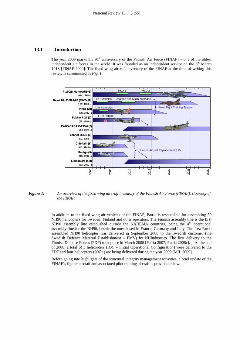
The usual approach in practical CFD is to apply Reynoldsaveraged equations. Detached EddySimulation (DES) is a promising approach at high angles of attack (AoA) and at high Reynoldsnumbers (Re). Cooperation with Helsinki University of Technology has started in order to applyDES for the F18C aircraft. An example of the DES results is the flow structure over a delta wingin Fig. 6.
Figure 6: Detached Eddy Simulation (DES) results of a 70° delta wing with a sharp leading edge atα=27° and Rec=1.56x10⁶. Instantaneous (left) and timeaveraged (right) isosurfaces ofentropy coloured by pressure coefficient are presented. Courtesy of Finflo Ltd.
Fluid structure interaction (FSI), i.e. coupling with FEA has been made so far explicitly byiterating between NASTRAN and FINFLO [ICAF 2007 Chapter 13.5.1.2]. In a new project, madein cooperation with Patria Aviation Ltd. this coupling is made using a simplified compliancematrix based on the original matrix from NASTRAN [Malmi 2008]. Using the simplified matrixthe FSI problem will be solved inside FINFLO and the iterations needed with NASTRAN areminimized.
Cooperation between Finflo Ltd. (Finland) and CFS Engineering (Switzerland) is continuing.Meetings have been arranged to handle technical aspects and general CFD development. CurrentCFD studies concentrate on the influence of the wing tip missiles.
13.2.1.2 Flight simulationsPrevious activities of the flight simulations to support the structural fatigue life management havebeen highlighted in e.g. [ICAF 2007 Chapter 13.6.3.1.1]. For years the FINAF has been fundingthe development of the lowcost flight simulation software which has been (and will be) utilisedamong the national research network in various projects (e.g. Chapter 13.3.3). Modular designallows different aircraft models to be implemented into simulations. Among the most importantones is the F18C aircraft model.

National Review 13 / 12 (55)
The associated elements (software / hardware) have been upgraded when needed in order tomaintain the simulation capability in a level corresponding to the actual flying of the FINAFaircraft. The following provides an update of the activities:
– Configuration and interface management, including software updates (e.g. compatibilityaspects with new versions of COTS (commercial offtheshelf) elements such asMatlab/Simulink) and user support
– Implementation of the flight control system (FCS) of the F18 Hornet control laws (v10.7)to facilitate realistic simulations i.e. correspondence between simulations and actual flights
– Update of the aerodynamic model of the F18 Hornet and its implementation in thesimulation scheme [Kaarlonen & Öström 2008].
– The engine model is being improved by TKK [Soimakallio & Vesaoja 2008] in view of e.g.from steadystate thrust [ICAF 2003 Chapter 4.1] to more realistic (dynamic) thrustfeatures.
– Trimming routine development to properly initialise the aircraft for simulation in selectedflight conditions
– Postprocessing features’ improvements to e.g. improve the quality of the visualisations ofthe simulated flights
– VRML visualisations’ improvements to enhance graphicness and animations for the“debriefings”
– HUD display development and implementation to provide the “pilot’s view” during thevisualisations of the simulations (see Fig. 9). The HUD implemented can be tailored to theuser’s preferences.
– Improvements in the inverse simulation capability [Öström 2007, Öström 2007b, Karelahti,Virtanen, Öström 2007, Karelahti, Virtanen, Öström 2008]
An overview of the lowcost HUTFLY2 simulator is provided in Fig. 7.
Figure 7: An overview of the HUFLY2 lowcost flight simulator tailored to the FINAF F18C Hornet.Picture courtesy of VTT.

National Review 13 / 13 (55)
13.2.1.3 Hornet FE modelling – updatePrevious development phases of the global (coarse) Finite Element (FE) model of the FINAF F18C Hornet have been outlined in [ICAF 2007 Chapter 13.5.1.1]. Since then, the dynamicbehaviour (mode shapes and frequencies) of the FE model has been verified by comparisons withresults obtained with an OEM FE model used for flutter analyses [Malmi & Liius 2007]. Also, themethod and tools for transferring the aerodynamic loads from CFD analyses onto the global FEmodel have been updated, and the procedure for creating balanced load cases (by adjusting theaerodynamic loads) was automated [Malmi 2008]. Verification of the global FE model of the wingwith full scale fatigue test measurement data, received from a foreign operator of the F/A18aircraft under the auspices of FISIF (F/A18 International Structural Integrity Forum), has beencompleted.
The work with the FE detail modelling, which was started earlier [ICAF 2007 Chapter 13.5.1.1]based on the assessment of the fatigue critical structural locations of the FINAF Hornets, has beencontinued by preparation of some new detailed FE models (Fig. 8): Outer wing front spar region[Liius & Turkia 2007], outer wing fold region [Salonen 2007] and the engine bay door region nearFS Y657.35 [Orpana & Liius 2008].
The fatigue life estimates for these locations have been determined by Patria in two ways: Forlocations for which applicable strain gauge data were available, the load spectra (strain gauge data)of a set of ten MiniHOLM 1 test flights representing FINAF average usage were used. Forlocation where applicable strain gauge data was not available, relative stress level comparisons(using FE detail models of different configurations, Fig 8a) between the cracked configuration (asper the OEM fatigue test) and the enhanced FINAF configuration were used. Due to the severeusage of the aircraft by the FINAF (Fig. 4), the life estimates show the need not only for carefulindividual aircraft fatigue tracking (IAT) according to the real usage, but also for preemptivetreatments for some locations.
The structural locations which have been found critical on the basis of the FINAF representativeset of ten flights [ICAF 2007 Chapter 13.5.1.3.1], are being continuously monitored with the twoHornets equipped with the HOLM instrumentation suite (see Chapter 13.2.2.1). For most of thesestructural locations also flight parameter based neural network fatigue tracking methods have beendeveloped (see Chapter 13.2.2.3). With these tools the FINAF F18 tailnumberspecific fatigue lifeconsumption can be analysed starting from the maiden flight, as the flight parameter data for allflights have been stored (MU data).

National Review 13 / 14 (55)
a
b
c
a
b
c
Figure 8: Examples of the FINAF F18 Hornet’s most recent detailed FE models: a) Outer wing frontspar region (note the different models for relative stress level comparisons of differentconfigurations); b) Outer wing fold region; c) Engine bay door region near FS Y657.35.Courtesy of Patria Aviation Oy.

National Review 13 / 15 (55)
13.2.2 Fatigue tracking systems
13.2.2.1 From HOLM flight tests to routine squadron servicePrevious research activities of the two FINAF F18 HOLM jets can be found in [ICAF 2007Chapter 13.5.1.3.3]. The two aircraft were delivered to the FINAF as planned: HN432 inSeptember 2006 to the Lapland Air Command e.g. [Miettinen 2006; Laakso 2006] and HN416 inApril 2007 to the Satakunta Air Command e.g. [Miettinen 2007; Laakso 2007b]. Like the otherHornets the two HOLM jets will be rotated also in the Karelian Air Command according to themaintenance schedule.
The early “research” configuration flights (MiniHOLM I) have been reported earlier [ICAF 2007Chapter 13.5.1.3.1 – 13.5.1.3.2]. Since then, the “production” version of the two HOLM onboardsystems have collected statistically reliable flight data from routine fleet usage of the FINAF forover 700 flights. The production flights have been and will be analysed and reported as the flightdata is delivered from the FINAF squadrons to VTT:
– To test and fine tune the ground system’s analysis and reporting procedures [Laakso et al2007; Laakso et al 2007b; Viitanen, Laakso, Janhunen, Merinen 2007], the first fistful offlights were analysed and reported in [Laakso 2007];
– Up to 261 flights were analysed and reported in [Viitanen, Laakso, Merinen 2008] and thefunctionality of the ground analysis system was assessed [Laakso, Koski, Viitanen 2008];
– Up to 435 flights were analysed and reported in [Viitanen, Laakso, Merinen 2009].– The remaining flights (up to the 700+ flights flown) are being analysed during the writing
of this report.
Owing to the periodic calibration [Liukkonen 2007; Liukkonen 2007b; Liukkonen 2008;Liukkonen 2008b] and maintenance [Viitanen & Merinen 2008] activities the HOLM “production”system works very well i.e. the quality of the strain signals is good (no spikes found) and all therecordable strain data has been captured (minimal missing data). Thus, the HOLM data are usedfor various research purposes as described below.
13.2.2.2 Flight manoeuvre identification (FMI)Research efforts related to Flight Manoeuvre Identification (FMI) have been many, which havebeen conducted in cooperation with (alphabetically) Patria Aviation, TUT/DSP and VTT. Theobjective of the project is to develop an ability to identify damaging events on flight and use thegathered information for structural integrity management. The information could be used in pilottraining and mission planning e.g. [ICAF 2001 Chapter 2.2]. That would enable lower damagerates and therefore extend the life of structures.
An overview of the joint FMI activities between the FINAF, Patria, TUT/DSP and VTT arehighlighted in Fig. 9. The base of the FMI activities is the available flight parameter data,especially the HOLM data. VTT verifies and analyses the HOLM data, and peruses the data toidentify and visualise the most damaging flights and the manoeuvres therein. Patria contributesespecially to the structurerelated analyses of the flight parameter recordings (MU data). Patriaexamines the connection between damage caused by the manoeuvres and the flight parameters,i.e., the reasons behind the damage. TUT/DSP develops signal processing and data miningmethods for the flight parameter analysis to find similar manoeuvres in an automatic manner fromthe bulk of the HOLM data. These methods aid in utilising the extensive flight recordingsdatabase. With joined efforts, the parties can rise to the challenge of this multidisciplinaryresearch. More details of the FMI activities are provided below and in ICAF 2009 oralpresentation ”Towards automated flightmaneuverspecific fatigue life analysis” [Jylhä,Ruotsalainen, Salonen, Janhunen, Viitanen, Vihonen, Visa 2009].

National Review 13 / 16 (55)
Expertisewith
signal processingand data m
ining
Amana
tool development
Expertisewith
aircraft structuresand their analyses
Amana
tool testing
Expertise with signal processing and data mining
Amana tool development
Expertise with HOLM data analyses
Amana tool validation
HOLM 1 (HN432) (2006 PWD)
HOLM 2 (HN416) (2006 PWD)MUX
dat
a (MU
+ HO
LM)
Expe
rtise
withHO
LM d
ata a
nalys
es
MU
data
Expe
rtise
with
airc
raft
stru
ctur
esan
d th
eir a
nalys
es Expertisewith
signal processingand data m
ining
Amana
tool development
Expertisewith
aircraft structuresand their analyses
Amana
tool testing
Expertise with signal processing and data mining
Amana tool development
Expertise with HOLM data analyses
Amana tool validation
HOLM 1 (HN432) (2006 PWD)
HOLM 2 (HN416) (2006 PWD)MUX
dat
a (MU
+ HO
LM)
Expe
rtise
withHO
LM d
ata a
nalys
es
MU
data
Expe
rtise
with
airc
raft
stru
ctur
esan
d th
eir a
nalys
es
Figure 9: An overview of joint Flight Manoeuvre Identification (FMI) research efforts between theFINAF, Patria Aviation Oy, TUT/DSP and VTT. Amana is a Matlab tool for flight manoeuvredetection, developed by TUT/DSP. Picture courtesy of VTT / Patria / TUT/DSP.
13.2.2.2.1 Flight segmenting and model building for damaging flight manoeuvres
Model based FMI requires models of the damaging manoeuvres. To expand the earlier work byTUT/DSP on structural vibration modelling for automated aircraft fatigue monitoring [ICAF 2007Chapter 13.6.3.1.2] and by Patria on parameter based fatigue life analysis of F18 aircraft [ICAF2007 Chapter 13.6.3.1], TUT/DSP proposed an automated FMI procedure based on the flightparameters.
The FMI process developed by TUT/DSP comprises three steps: choosing, modelling andidentifying manoeuvres. As the first step of the process, a representative manoeuvre is chosenfrom the flight parameter recordings by an experienced analyst. Next comes the modelling: Forevery manoeuvre to be identified, a model is built based on the chosen representative manoeuvres.The chosen flight parameters are quantised to three levels to enable a consistent treatment ofdifferent parameters. Thus, the quantised, chosen flight parameters within the representativemanoeuvre form the model to be used in the comparison i.e. the similarity of the model to patternsthat exist in the data is measured (socalled model based pattern recognition). The last step of theprocess is fully automatic FMI: In this step, an identification algorithm based on the built modelsis used to detect manoeuvres from the unanalysed flight parameter recordings.
To cope with the reality – the same manoeuvres can be performed in slightly different ways andtheir duration can vary – the Dynamic Time Warping (DTW) algorithm to handle the temporalvariations is used. A DTW matrix is calculated between the modelled representative manoeuvreand the whole flight using the quantised flight parameters that were chosen at the modelling step.Manoeuvres’ starts and stops are detected from the DTW matrix which provides a similarityvalues for the patterns. Good applicability to different manoeuvres has been verified by comparing
National Review 13 / 17 (55)
the results of the automated FMI procedure with those identified manually by an experiencedanalyst with pilot background. Further details of the automated FMI procedure can be found in thearticle [Ruotsalainen, Jylhä, Vihonen, Visa 2009] and in the ICAF 2009 presentation “Towardsautomated flightmaneuverspecific fatigue life analysis” [Jylhä, Ruotsalainen, Salonen, Janhunen,Viitanen, Vihonen, Visa 2009].
13.2.2.2.2 Identification and interpretation of damaging manoeuvres
Patria has worked with pattern recognition using amounts of the memory unit (MU) data and theHOLM data from FINAF F18’s to analyse the reasons for the fatigue damage accumulation.Patria has developed a corresponding method to the FMI procedure. In the research, flights aredivided into damaging segments according to strain level and high vibrations in strain gaugesignal. That yields hundreds of interesting segments. A clustering method was tested to classify thepatterns and grouping similar manoeuvres into the same group. Several clusters are obtained andtheir centres can be used as templates of the damaging manoeuvres [Salonen 2008].
Patria also tested the FMI method for the detection of flight manoeuvres causing damage to thevertical tail and wing fold. The models were manually created and they were pure manoeuvres e.g.splits. With good accuracy, the FMI method was able to detect the manoeuvres causing similardamage to the structure. To understand reasons for the structural damage, the identifiedmanoeuvres were inspected. As expected, the typical hard flying causes major part of the damage.On the other hand it was found that small changes in flying could have significant impact indamage. For example, lowering the angle of attack (AoA) rate and the time spent in the high AoAregime would substantially reduce vertical tail damage [Salonen 2008].
Up to now the feasibility of the FMI for comprehensive structural management has beendemonstrated. This research branch is still to be continued i.e. further studies in this research areneeded to get full benefits.
13.2.2.2.3 Search of similarity between “similar” flight manoeuvres
Using the bulk of collected and analysed HOLM data (Chapter 13.2.2.1), VTT’s FMI efforts arefocused on finding the most damaging manoeuvres for a given structural detail on the basis of themost damaging sorties and flights identified. Having identified the most damaging flight for agiven structural detail, the time segment producing the highest calculated damage is located. Usingthe Flight Analyzer [ICAF 2007 Chapter 13.4.4.2] tool, the manoeuvre producing the highestcalculated damage is visualised. Next, the most significant flight parameters (and their envelopei.e. their min and max values together with their synchronised time histories) representing the“image” or “pattern” of the manoeuvre in question are identified. With the “pattern” obtained,similar “patterns” (flight manoeuvres similar to the most damaging one) are searchedautomatically (using the method developed by TUT/DSP described above) from the bulk of theanalysed HOLM data. As an example, the automatic “pattern” search for an approximately 300flights took less than one hour wall clock time.
Although the scatter in calculated damage for the “similar” manoeuvres is noteworthy, the methodis being used in the search of the most damaging manoeuvres. The work performed thus farprovides a solid starting point to further investigate the reasons (the connection between flightparameters’ temporal behaviour and damage) why nominally similar manoeuvres providesignificant scatter in the calculated damage.

National Review 13 / 18 (55)
13.2.2.3 Flight parameter based fatigue life analysis of aircraft structuresPrevious research efforts on the flight parameter based fatigue life analysis of aircraft structures,aimed at enhanced individual aircraft fatigue life tracking (IAT) of the FINAF F18’s using flightparameters, have been summarised in [ICAF 2007 Chapter 13.6.3.1; ICAF 2005 Chapter 5.3]. Indepth description of the program can be found from [Tikka & Salonen 2007; Jylhä, Vihonen, AlaKleemola, Kerminen, Tikka, Visa, 2007].
The project is reaching the end of the developing phase. Methods and tools for individual aircraftfatigue life tracking of the FINAF F18 aircraft (Fig.10) have been developed and implemented inthe project.
Figure 10: An overview of the analysis chain of the flight parameter based fatigue life analysis. Courtesyof Patria Aviation Oy.
The most recent actions related to Parameter Based Fatigue Life Analysis are: The training of newneural networks (NNs), validation of results by using amounts of HOLM data and adding newstructural details into the analysis. The analysis should be in routine use and tens of thousands offlights analysed by the end of 2009. The following provides an overview of the most recentachievements.
13.2.2.4 Analysis validation and NN training by using hundreds of HOLM flights’ dataTwo FINAF F18 HOLM aircraft have gathered a lot of strain gauge data to exploit on analysisdevelopment work. Therefore, neural network (NN) training data selection and utilisationprocedures have been developed to cope with that. The training data has been selected to cover theentire flight envelope, including flight parameter extremes as well as whole strain response area.
The analysis has been developed to fulfil the essential requirements of the DEF STAN 00970.The standard presumes that the data used in the development phase is stored and the whole processis well documented. The HOLM data from the two aircraft enable proper validation andcalculation of performance metrics. In addition to an extensive set of training data flights, there arehundreds of distinct flights to be used as an independent validation set.
All flights during 20022007 for 5 aircraft have been analysed in order to confirm the properfunction of analysis environment. No major problems were encountered in the analysis.

National Review 13 / 19 (55)
13.2.2.5 Extending analysis capability by new structural detailsIn addition to the initial 10 structural details, 5 more will be added to the analysis by Patria. Ofthese, the Upper Outboard Longeron and Dorsal Longeron are already implemented, Fig. 11. Theremaining three details will be chosen by the end of 2009.
Dorsallongeron
Upperoutboardlongeron Dorsal
longeron
Upperoutboardlongeron
Figure 11: Structural details being included into the production level analysis environment. The two newdetails (upper outboard longeron and dorsal longeron) are highlighted using violet colour. Inaddition, three more will be added by the end of 2009. Courtesy of Patria Aviation Oy.
13.2.2.5.1 From instrumented to new (uninstrumented) structural locations
The number of the structural details of interest in view of fatigue tracking exceeds that provided bythe onboard HOLM instrumentation suite [ICAF 2007 Chapter 13.5.1.3.3]. Therefore, additionallocations have been obtained with the use of Patria’s FE models e.g. [Malmi, Liius, Orpana 2007].Patria has prepared the submodels and associated transfer functions from the strain gaugelocations to selected noninstrumented locations of interest.
These data were provided by Patria to VTT, where the data have been integrated into the HOLMground analysis environment [Laakso & Koski 2007; Laakso & Koski 2008]. In summary, withthe above additions the HOLM ground analysis environment now has the capability to analyse 22noninstrumented locations in addition to those with strain gauges.
To complement the above, there will be further additions to the structural locations to bemonitored: Transfer functions up to eight (8) new structural locations will be prepared by Patria,while slight adjustments (e.g. some mirroring of locations from port to starboard side and/or viceversa) are being prepared and implemented at VTT [Laakso, Koski, Viitanen, 2009].

National Review 13 / 20 (55)
13.2.2.6 The Hawk OLM programPrevious activities related to the Operational Loads Monitoring (OLM) program of the FINAFHawks is highlighted in previous ICAF reviews e.g. [ICAF 2007 Chapter 13.4.3].
13.2.2.6.1 On the future of the Hawk OLM rolling program
All OLM flights until the end of 2006 (total of 1 300+ flights) were analysed and reported usingthe ground station developed entirely by VTT [Viitanen, Laakso, Bäckström, Janhunen, Merinen,Ovaska 2007]. Using the fatigue analysis database, the analyses included the FI consumption2 (onthe basis of g counts), the fatigue damage rate and life estimates (in FH) as well as the mostdamaging flights for the structural assemblies (fuselage, wing, tailplane, vertical tail) on the basisof the collected strain gauge data [Viitanen, Laakso, Janhunen, Merinen, Ovaska 2007].
Since then, the changes as outlined in Chapter 13.1.2 have compromised the continuity of theindividual aircraft tracking (IAT) part of the HW OLM program which was intended to be arolling program until the planned withdrawal of the entire FINAF Hawk fleet (Fig. 12): Theroutine OLM data analyses have ceased as the two OLM aircraft (HW319 and HW348) are outof service. The FINAF decisions regarding the future of the OLM are pending.
HW348 OLM I (2000 PWD)
HW319 OLM II (2001 PWD)
PWD FIAF HawkYESTERDAY
HW319 (2001 4/06)
HW348 (2001 6/07)
TODAY
TIME
Mk51 OLM III ?
20XX
TOMORROW ?
Mk66 OLM III ?
and / or ?
Extended PWD
Hawk Upgrade (Mk51 / 12 + Mk66 / 18 )
today
HW348 OLM I (2000 PWD)HW348 OLM I (2000 PWD)
HW319 OLM II (2001 PWD)HW319 OLM II (2001 PWD)
PWD FIAF HawkYESTERDAY
HW319 (2001 4/06)HW319 (2001 4/06)
HW348 (2001 6/07)HW348 (2001 6/07)
TODAY
TIME
Mk51 OLM III ?
20XX
TOMORROW ?
Mk66 OLM III ?
and / or ?
Extended PWD
Hawk Upgrade (Mk51 / 12 + Mk66 / 18 )
today
Figure 12: The two HW OLM jets have ceased collecting the OLM data, HW319 in April 2006 and HW348 in June 2007. Selected FINAF Hawks are being upgraded at Patria Aviation Oy. Thefuture of the Hawk OLM is pending. Picture courtesy of VTT.
The need for the OLM embodiment is obvious, as the jet trainers are still being used in Kauhava:Currently the only means to estimate the sudden increase in the structural fatigue life consumption(Fig. 3) could be done on the basis of the flight reports (LSI) i.e. the recorded OLM datarepresenting Kauhava usage is rare.
2 The average FI consumption results calculated at VTT using the OLM data (FIHW319 = 13,8; FIHW348 = 15,7) were well inagreement with the results calculated by the FINAF and shown in Fig. 3.

National Review 13 / 21 (55)
13.2.2.6.2 Hawk OLM’s current activities (onboard configuration and ground analysis system)
Activities towards replacing the onboard data storage unit (data tape) with a more reliable solidstate recorder have started [Liukkonen & Teittinen 2008]. Embodiments to the onboard OLMinstrumentation suite are likely to be implemented in near future, as there may be strain datachannels of little use and the remaining FINAF Hawks will not have the original3 (premod 999)wing.
The use of GPS data to support structural life estimation has been investigated [Sailaranta 2008;Sailaranta 2008b; Laakso 2009], but due to the ongoing Hawk upgrade (glass cockpit) this optionis no longer deemed necessary.
The ground analysis environment [ICAF 2007 Chapter 13.4.3.2] has been further developed, as thesame analysis environment is used for the FINAF Hawks as well as Hornets. The analysis toolswithin the ground station now include the local strain (εN) approach [Bäckström, Liukkonen,Laakso, Viitanen, Koski, Teittinen 2007] to support the previously integrated methods (“stresslife” i.e. SN and “fracture mechanics” i.e. da/dN). It should be noted that the current groundanalysis configuration is continuously developed to further improve the life prediction accuracy[Bäckström, Liukkonen, Laakso, Viitanen, Koski, Teittinen 2009].
Flight report (LSI) data will be used to estimate the structural fatigue life consumption of theKauhavabased Hawks and to compare the FI consumption results with those obtained prior toKauhavabased flying. Efforts to define structuralspecific life consumption metrics to thosestructural assemblies subjected to buffetinduced severe dynamic loading (e.g. aft fuselage,tailplane, fin) are underway.
The FMI activities are continuing by flight simulations and by investigating proper selectioncriteria in order to identify the most damaging flight manoeuvres e.g. [Janhunen 2007]. One goal isto create flight visualisation routines such that the most damaging flights could be visualised tofacilitate the “conference with the aircrew to try and avoid flying in severely damaging flightconditions unless specific training or operational reasons dictate otherwise” [ICAF 2001 Chapter2.2].
3 Research efforts concerning the structural integrity of the recently retired original (pre mod 999) wings of the FINAF Mk51Hawks have been reported e.g. in [Koski et al 2007; Koski et al 2009.]

National Review 13 / 22 (55)
13.2.3 Structural integrity of composite materials
13.2.3.1 Thermographic studies – updatePrevious research efforts on the thermographic investigation based on phase transition of water at0 °C to find structural flaws due to moisture ingress were highlighted in [ICAF 2007 Chapter13.6.4.5]. Thermographic research has continued in cooperation with the FINAF and VTT to finda reliable routine to inspect multiple flight control surfaces in a reliable manner (rudder, trailingedge flap and horizontal stabilizer). The investigation has concentrated on the inspection methodwhere the whole structure is first cooled below the freezing point of water before warming thestructure in room temperature; the inspections are done during the warmup period.
Thermographic inspection based on the phase transition of water has already proved earlier to bevery sensitive to moisture: Artificial defected areas had showed that very small amounts (less than1 g) of water in the laminate honeycomb (carbon fibre/epoxide composite with aluminiumhoneycomb core) interface can be detected by exploiting the phase transition of water, Fig. 13.
°C
20
15
10
5
0
5
10
15
20
0 3:20 6:40 10:00 13:20 16:40 20:00
0,0°C
12,0°C
0
5
10AR01AR02
AR03
Figure 13: Penetrated water (in laminate/honeycomb interface) detected with thermographic inspectionbased on phase transition of water. AR01 refers to red line (0.7 g water), AR02 refers to blueline (0.1 g water) and AR03 is a reference of dry area (green). Picture courtesy of VTT.
Critical areas of the rudder are assumed to be around the hinges due to the possible leakage in thesealing of the grounding grooves. Thus, the main effort of seeking moisture from the structure wasconcentrated to these areas.
Optimal Inspection Frame (OIF) time research with real rudder structure displayed some abnormalwarmingup behaviour around the upper hinge of the rudder, Fig. 14.

National Review 13 / 23 (55)
2,0°C
15,0°C
0
10
Normalbehaviour
NormalbehaviourAbnormal
behaviour
Figure 14: Moisture detected under the upper hinge of the rudder test sample. Normal and abnormalwarmingup behaviour shown. Picture courtesy of VTT.
Individual images do not explain reliably the reason for the abnormal behaviour, but they showclearly the area of interest to be further inspected as a sequence of thermographic images (e.g.temperature curves from pulse thermography or thermography exploiting phase transition ofwater) or with other NDT methods sensitive to moisture penetration. Warmingup curve ofdifferent surface points of the rudder showed very small plateau at the curve, which referred to themoisture inside the rudder, Fig. 15.

National Review 13 / 24 (55)
15,00
10,00
5,00
0,00
5,00
10,00
15,00
20,00
25,00
0 5 10 15 20 25 30 35 40 45 50 55 60
Ai ka ( mi n)
Y0 5 °C 3h
Y1 5 °C 3h
Y2 5 °C 3h
Y3 5 °C 3h
A0 5 °C 3h
A1 5 °C 3h
A2 5 °C 3h
A3 5 °C 3hTem
pera
ture
[°C
]
Time [s]
Figure 15: Comparison of the temperature evolution of all measurement points of the rudder. Initialtemperature 5 °C, cooling time 3 hours. The plateau (slight deviation from expected) observedfor Y1 and A1 curves near 0°C refers to moisture inside the rudder. Picture courtesy of VTT.
Thermographic research with real aircraft structures showed the complicity of the inspection, dueto the additional (metallic) supporting structures and/or changes in material thicknesses inside thestructure. Sufficient amount of reference data (inspected nondefected structures) was found to bea very practical way of defining warmingup behaviour of nondefected structures. Speed of thewarmingup of the real rudder structure was inspected in order to find proper optimal inspectionframe (OIF) time for finding the penetrated water from each structure. An example of the OIF timeof different surface areas of the rudder structure can be seen (as a green colour) in Fig. 16.
10,0°C
22,0°C
10
0
10
20
10,0°C
22,0°C
10
0
10
20
10,0°C
22,0°C
10
0
10
20
10,0°C
22,0°C
10
0
10
20
10,0°C
22,0°C
10
0
10
20
10,0°C
22,0°C
10
0
10
20
O min 2 min 4 min
6 min 8 min 10 min
10,0°C
22,0°C
10
0
10
20
10,0°C
22,0°C
10
0
10
20
10,0°C
22,0°C
10
0
10
20
10,0°C
22,0°C
10
0
10
20
10,0°C
22,0°C
10
0
10
20
10,0°C
22,0°C
10
0
10
20
O min 2 min 4 min
6 min 8 min 10 min
Figure 16: Optimal inspection frame time for different areas of the rudder surface (green area in theimages). 0time refers the temperature where the first area reaches 5 °C. Picture courtesy ofVTT.

National Review 13 / 25 (55)
The warmingup behaviour of other structures was also investigated and the optimal inspectiontimes for interesting areas (inspection points) were determinated. Inspection of the other structuresis reported in [Saarimäki 2008; Saarimäki 2008b; QIRT2008].
The effects of environmental conditions were investigated to ensure reliable inspection conditionsfor the inspected structure. Different cooling temperatures and times were investigated to ensurethat the whole structure is frozen before the warming phase. Different defrosting conditionsshowed however that weather and cooling conditions affected strongly to the results. To preventthe condensation of moisture and hence formation of rime layer on the surfaces is a critical factor,which can be significantly reduced and even eliminated by cooling the whole aircraft or compositestructure in a hangar with proper ventilation.
13.2.3.2 Phased array ultrasonics of aircraft parts made of compositesUltrasonic NDI techniques applicable to the examination of aircraft parts made of either single ormulti layer composite materials have been studied at VTT [Lahdenperä & Leskelä 2009] incooperation with the FINAF, Patria Aviation and TKK. Ultrasonic phased array technique andsingle transducer technique were applied (pulse echo mode). Suitable equipment (ultrasonictransducers and equipment as well as a manual scanner) were used in the study. The examinedparts consisted of test samples containing artificial defects (crushed core, potted core, debonding,delamination, flat bottom holes), as well as a F/A18 horizontal stabilator of a foreign originretired from service after nearly 6000 FH, from which selected areas were chosen for theexaminations. The examination surfaces of the test samples were painted. The horizontal stabilatorwas painted “as is”. The examination volume included the surface laminate and the interface(adhesive layer) between the surface laminate and the honeycomb core.
The recorded ultrasonic data was used to generate B and C scans from the examined areas for thepurposes of data interpretation and reporting. The use of the B and C scans is helpful to gainunderstanding of the internal structure and defects therein, as long as there is a commonalitybetween artificial (test samples) and true (flown aircraft parts) structural features and internal flawcharacteristics. The B and C scans can also be applied to compare the results of consecutiveexaminations.
13.2.3.2.1 Test samples with artificial flaws
All flaws within the surface laminate of the test samples were detected with conventional andphased array ultrasonics. The artificial flaws within the interface between the surface laminate andthe adhesive layer were detected. The artificial debond between the adhesive layer and thehoneycomb core was not detected (the core was cut out manually with a sharp thin blade knifewithout damaging the adhesive layer). An example of the results is provided in Fig. 17.

National Review 13 / 26 (55)
Figure 17: Examples of B scans from test samples. Above: Artificial defects (7 drilled flat bottom holes ofdifferent depth). All holes were well detected. Each hole is giving rise to a double indication,due to the shape of the ultrasonic pulse. Below: Artificial defects (unbond within the adhesivelayer between the surface laminate and the honeycomb core). Three of the four flaws can beseen (marked with red arrows). Picture courtesy of VTT.
13.2.3.2.2 Horizontal stabilator
The achieved examination sensitivity was found to depend on the surface curvature (aerodynamicshape) of the horizontal stabilator skin and the geometric dimensions of the ultrasonic transducersused.
On the basis of the results, recommendations regarding proper equipment and procedures to beapplied in the examination of aircraft structural components fabricated of composite materialswere made.
13.2.3.3 Developments in metal bondingThe difficulties in developing durable and robust surface preparation techniques have limited theuse of bonded joints in highly loaded metal to metal and metal to composite structural joints inaircraft applications. The PAA and γGPS silane based techniques have matured to an acceptablelevel with aluminium. Some difficulties are still experienced with γGPS silane on titanium.However, no acceptable method has been available for structural steel bonding.
In the DIARC process the metal part is plasma treated in a vacuum chamber at room temperature.Ions with enough kinetic energy form a thin (from nanometers to microns) well adherent

National Review 13 / 27 (55)
amorphous and dense nanostructure when they hit the surface. The process is environmentally safeand economical. The surface is dense, hard, corrosion resistant, has very low coefficient offriction, and is also bondable to epoxy. In addition to epoxy bonding, the DIARC process can beused for coating tools, sliding parts and molds for lower friction and wear resistance, and forreplacing other environmentally hazardous corrosion protection coatings on metals (e.g. epoxyprimers containing chromates or cadmium often used with high strength steels). For epoxybonding the treated metal part does not need any additional primer. It also stays stable and isrobust to the bonding process. The DIARC pretreatment thus decreases the workload in the finalbonding and also decreases the requirements for the surface treatment stage of the process.
Testing has been performed with the AC130 SolGel and DIARC plasma coating surfacetreatment methods for metal bonding applications. Bare and clad 7075 aluminium, TiAl4Vtitanium, AISI 304 and AISI 4130N steels were bonded with the 120°C curable FM3002 epoxyadhesive. Wedge test specimens were tested at hot/wet (60°C/98%RH) environment and in neutraland salt hot (60°C) water immersion. The γGPS silane based AC130 SolGel treatment providedacceptable results at hot/wet conditions with bare and clad aluminium even without primer whengrit blast or suitable mechanical abrasion techniques were used. The crack growth was gradual andthe failure mode was over 95% cohesive. With titanium the BR 67471 primer improved thedurability of AC130 SolGel treatment to an acceptable level. AC130 SolGel with the AISI 301steel provided a reasonable crack growth but unacceptable failure mode at hot/wet conditions.
The testing of the DIARC plasma coating with the 301 steel and titanium in epoxy bondingprovided very good results at hot/wet environment. The crack growth measured in the wedge testwas less than 5 mm in two days and the failure mode was 100% cohesive. The results were asgood as the best wedge test results achieved in aluminium bonding. The DIARC plasma treatmentincreases the durability of bonded steel joints to the same level as composite to composite joints,which opens a wholly new option to design light bonded metal/composite joints and structures forspace, air, naval, land, construction and industry applications.
Immersion tests in neutral tap water and in salt water (North Baltic Sea water with 0,5% saltcontent) have been accomplished. Results showed that DIARC coating provides good results withaluminium, steel and titanium also in immersion. With high strength steel also the edges have to becoated for preventing corrosion between base material an the coating. AC130 SolGel treatmentprovided inconsistent results in hot water immersion tests. A more detailed description of theabove metal bonding activities can be found in the ICAF 2009 poster presentation [Aakkula,Lumppio, Saarela 2009].
13.2.3.4 Progressive failure analysis of composite laminates – updateResearch activities to come up with an analysis tool (ABAQUS & GENOA) of progressive failureanalysis of composite laminates subjected to static loading were highlighted in [ICAF 2007Chapter 13.6.4.3]. Recent research activities at TKK are highlighted below.
The analysis of laminate strength after the First Ply Failure (FPF) has been studied for decades.Traditional strength based failure criteria and damage models based on stiffness reductions ofpartially failed plies were investigated in a worldwide failure exercise [Soden, Hinton, Kaddour,1998]. Some contestants argued that the strength data provided for unidirectional (UD) ply was notadequate to predict laminate failure. The transverse insitu strength of an embedded ply in alaminate is greater than the transverse strength of a UD laminate. FE analysis is nowadays acommon practice when large structures are analysed. The calculated strengths for structuresincluding stress concentrations are mesh dependant because small elements close to the stressconcentrations predict high stresses. This study addresses these two problems and presentsanalysis results for notched glass fibre laminates using a traditional progressive failure model andan energy based damage model. The results are calculated with various mesh sizes and the insitustrength effects are taken into account. Ply data and reference data for two laminates weremeasured.
Tests were performed on glass fibre prepreg laminates. Six specimens were used for each testperformed. The damage progression in the laminate was simulated using two different damagemodels; ply discount method and an energy based damage model. Additionally to the testedlaminates, a notched UD laminate was analysed in transverse tension loading. The failure loads

National Review 13 / 28 (55)
were calculated with three different mesh sizes. A closeup of the meshes is shown in Fig. 18 andthe failure loads in respect to the element size are shown in Fig. 19, in which the measured failureloads with the standard deviation are shown as a horizontal grey area. The software used in theanalysis was ABAQUS.
Figure 18: Meshes with 0.8 mm (left), 0.4 mm (middle) and 0.2 mm (right) elements used in the study.Courtesy of TKK.
Thin plies
Thick plies
Test results
120
140
160
180
200
220
0,20,40,60,8Element length (mm)
Failu
re lo
ad (M
Pa)
Ply discount model thickEnergy based damage modelTest results
Thin plies
Thick plies
Test results
120
140
160
180
200
220
0,20,40,60,8Element length (mm)
Failu
re lo
ad (M
Pa)
Ply discount model thickEnergy based damage modelTest results
Figure 19: Failure loads vs. Element size using two damage models. The measured failure loads with thestandard deviation are shown as a grey colour. Courtesy of TKK.
For UD laminates the energy based damage model gave good results irrespective of the elementsize but for multidirectional laminates the results were mesh dependant with both methods. Thedependence on mesh size was greater for the laminate with thin plies than or the laminate withthick plies. More work needs to be done to determine the effect of laminate layup and materialproperties on the mesh dependency. As expected, the laminates with thin plies carried higher loadsthan the laminates with thick plies. This indicates that the strength of an embedded ply, i.e. the insitu strength, is a function of the layer thickness. The equations proposed by Camanho [Camanho
National Review 13 / 29 (55)
et al 2006] worked well to model this phenomenon. The results for the final failure load agreedwell with the test results [Skyttä, Saarela, Wallin 2008].
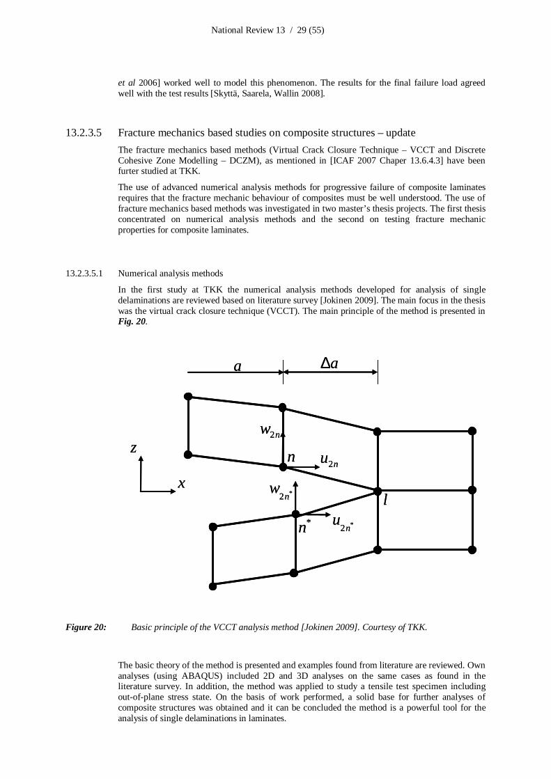
13.2.3.5 Fracture mechanics based studies on composite structures – updateThe fracture mechanics based methods (Virtual Crack Closure Technique – VCCT and DiscreteCohesive Zone Modelling – DCZM), as mentioned in [ICAF 2007 Chaper 13.6.4.3] have beenfurter studied at TKK.
The use of advanced numerical analysis methods for progressive failure of composite laminatesrequires that the fracture mechanic behaviour of composites must be well understood. The use offracture mechanics based methods was investigated in two master’s thesis projects. The first thesisconcentrated on numerical analysis methods and the second on testing fracture mechanicproperties for composite laminates.
13.2.3.5.1 Numerical analysis methods
In the first study at TKK the numerical analysis methods developed for analysis of singledelaminations are reviewed based on literature survey [Jokinen 2009]. The main focus in the thesiswas the virtual crack closure technique (VCCT). The main principle of the method is presented inFig. 20.
a∆
l
a
z
xn
*n
2nw
2nu
*2nu
*2nw
a∆
l
a
z
xn
*n
2nw
2nu
*2nu
*2nw
Figure 20: Basic principle of the VCCT analysis method [Jokinen 2009]. Courtesy of TKK.
The basic theory of the method is presented and examples found from literature are reviewed. Ownanalyses (using ABAQUS) included 2D and 3D analyses on the same cases as found in theliterature survey. In addition, the method was applied to study a tensile test specimen includingoutofplane stress state. On the basis of work performed, a solid base for further analyses ofcomposite structures was obtained and it can be concluded the method is a powerful tool for theanalysis of single delaminations in laminates.

National Review 13 / 30 (55)
13.2.3.5.2 Fracture mechanics properties of composite laminates
The second thesis study at TKK concentrated on testing fracture mechanics parameters forcomposite laminates [Hintikka 2009]. The existing test methods and standards were reviewedincluding pure mode I, II and III test methods and various mixed mode test methods. In addition,the challenges in actual testing as well as interpretation of test results were reviewed. The testfacilities were designed including test fixtures and measurement arrangements, Fig. 21.
Figure 21: Left: Testing the mode I properties for laminate using standard DCB test method (DCB –Double Cantilever Beam). Right: Testing the mixed mode I/II properties for a laminate usingthe MMB test method (MMB – Mixed Mode Bending). Courtesy of TKK.
The basic properties in mode I, II and mixed mode I/II were measured for AS4/35016 prepregmaterial. The test parameters included the effect of the layup, environmental exposure and the useof hybrid metal/composite test specimens. Based on the work the capability to make fracturemechanic testing was obtained and basic properties for the AS4/35016 were measured that canlater be used as a reference data.

National Review 13 / 31 (55)
13.2.4 Structural integrity of metallic materials
Various surface renewal activities take place on fleet aircraft to remove incipient cracks arising atstructural critical locations in order to make the structure crackfree and more fatigue resistant. Ofparticular interest in these surface renewal activities are those carried out in regions containingetched surfaces, which – for the FINAF F18C/D aircraft – are due to e.g. preIVD processesduring the parts’ OEM manufacturing. The highlights of the associated research projects areprovided below.
13.2.4.1 Effect of chromic and phosphoric acid anodizing on the fatigue life of 7075T76The effect of anodizing on the fatigue life of 1,8 mm sheet aluminium alloy 7075T76 werestudied by Patria and TKK. The test series included 56 specimens: 20 clad, 20 chromic acidanodized and 16 phosphoric acid anodized specimens. The stress ratio was R = 0,3. For allsurface preparation methods four specimens were tested at each studied stress level. The fatiguetests were performed by TKK. The main conclusions were [Linna 2007b]:
If the fatigue stress level is over 200 MPa, the effect of surface preparation is minimal. If the fatigue stress level is under 200 MPa, phosphoric and chromic acid anodized
specimens were better than clad specimens based on average test results. The margin iseven more significant if the stress level is low enough ( 175 MPa).
In every stress level the scattering of the results was clearly lowest for clad specimens.
13.2.4.2 Effect of surface working methods on the fatigue life of 7050T7451 (R = 0,3)The effect of various surface working methods (shot peening, polishing and etching) on fatigue lifeof laboratory specimens made of two common 7000 series (7050T7451 and 7175T7351)subjected to completely reversed cycling (R = 1) were highlighted in [ICAF 2007 Chapter13.6.6.1]. These experiments were extended by Patria and TKK to obtain data for also R = 0,3loading as described below.
The effect of surface etching, polishing and shot peening on fatigue life of laboratory specimensmade of 7050T7451 aluminium alloy were investigated. Thickness of the specimens was 6,35mm, the stock material thickness being 100 mm. All specimens were manufactured in L rollingdirection. The total number of specimens was 48 including 12 basic (as machined), 12 etched, 12polished and 12 shot peened specimens. The tests were made using three different constantamplitude stress levels.
Shot peening with Almen intensity of 0,14 mmA was made by using ceramic beads. The surfaceroughness of the polished specimen was 0,4 m Ra 0,6 m. Etching was similar to theproduction preIVD coating process. The fatigue tests were performed by TKK. The followingmain test results and LIF’s (Life Improvement Factors) were obtained [Linna 2007]:
if the maximum stress level is higher than 0,5 ⋅ σy (σy = yield stress) polishing is moreefficient than shot peening resulting LIFpolishing = 2… 3,5.
LIFpolishing is always higher than 2. Shot peening also improves the fatigue life of the structure, but the benefit is not
substantial, if the stress level is relatively high ( 0,5 ⋅ σy). Lower stress levels equal better shot peening effects. At low stress levels ( 0,45 ⋅ σy), LIFshot_peening can be more than 5. The influence of etching (and IVD coating) is significant, LIFetching can be 0,5 or less

National Review 13 / 32 (55)
13.2.4.3 Effect of hole preparation methods on the fatigue life of mechanical jointsThe effect of hole preparation methods were tested by Patria and TKK using two different testsections. The first set of specimens were made of 3 mm thick Al 7050T74 plate (stock thickness100 mm) and 1,8 mm thick Al 7075T6 sheet. The test series consisted of single lap shear joints.Hole tolerances were Clearance Fit (C/F) and Interference Fit (I/F). The number of fasteners wassix in all specimens. 4x12 = 48 specimens were tested using 4 specimens for each SN –curvepoint. The fatigue tests were performed by TKK. The main results were [Linna 2007c]:
For 1,8 mm thick single lap shear specimens, the I/F hole tolerance did not produce fatiguelife improvement when comparing to the C/F hole tolerance in all tested stress levels.
For 3 mm thick single lap shear specimens, the effect of hole tolerance (I/F or C/F) wasminimal, but small life improvement factor can be achieved.
I/F is probably not suitable for single lap shear joints when using relatively thin sheets. More test series are needed.
The second series of tests were made of 4 mm thick Al 7075T76 sheet. The test series consistedof single and double lap shear joints. Hole tolerances were again C/F and I/F. The series includedalso Cold Worked (C/W) specimens. In the future also Force Mate (F/M) bushed specimens willbe tested. The number of specimens for each SN –curve point was as in the earlier test sectiontotalling 6x12 = 72 specimens. The number of fasteners per specimen was six. The main resultswere [Linna 2009]:
For the single lap shear joint, LIFI/F =1,3 when comparing to the C/F joint. For the single lap shear joint, LIFC/W =2 when comparing to the C/F joint. For the double lap shear joint LIFI/F =2 when comparing to the C/F joint. For the double lap shear joint LIFC/W =3 or more when comparing to the C/F joint.
13.2.4.4 FISIF Surface Renewal Joint Coupon Program (SRJCP)The F/A18 users’ FISIF consortium – alphabetically from Australia, Canada (project lead),Finland, Switzerland and the USA – are conducting materials tests to complement the existing dataregarding the LIF due to surface renewal operations to help further substantiating the selectedpotentially simple and costeffective solutions for fatigue critical areas. The background andmotivation of these materials tests were provided in [ICAF 2007 Chapter 13.6.6.2].
Of the hundreds of specimens within the joint project, Finland’s share included the constantamplitude fatigue testing of approximately 60 coupon specimens (by VTT) of selected surfacefinishes:
– Machined, no surface renewal, cycled to failure– Pre IVD etched, no precycles / surface renewal, cycled to failure– Pre IVD etched, various amounts of precycles followed by surface renewal, then cycled to
failure– Anodized, no precycles / surface renewal, cycled to failure– Anodized, various amounts of precycles followed by surface renewal, then cycled to
failure
As the test program is underway, the time is not ripe for a more detailed appreciation of theexperimental results.
13.2.4.5 Fatigue management policies of the FINAF and the ASIMPThe fatigue management policies of the FINAF have been outlined in previous national reviews[ICAF 2001; ICAF 2003; ICAF 2005; ICAF 2007]. The tools and instructions for the ASIMPdocumentation for the fatigue life cycle management of the Hawks (meeting the requirements forthe remaining postmidlife structural integrity issues) and Hornets (structural lifing policy anddamage tolerance aspects) will be developed by Patria for the FINAF Hornet and Hawk aircraft.The first version of the FINAF Aircraft Structural Integrity Management Plan has been deliveredfor review to the FINAF. The ASIMP methodology follows MILSTD1530C guidelines.

National Review 13 / 33 (55)
13.2.4.6 Reflected (leaky) Rayleigh wave experiments on Canadian partsThe ultrasonic nondestructive testing method, Rayleigh wave technique, was applied in the testingof a selection of CF aircraft samples provided by Canada (the CF and L3 MAS) under theauspices of FISIF – F/A18 International Structural Integrity Forum. The samples consisted oflaboratory test coupons of the CF18 web taper section (Y453 bulkhead) and actual parts from theCF188727 aircraft retired from service. The purpose of the proofofconcept tests was to checkthe applicability of the Rayleigh wave technique to detect minute surface cracks from parts knownto have been subjected to either laboratory test loads (coupons) or flightinduced loads (aircraft188727 parts). It was assumed that there would be minute surface cracks resulting from thesecyclic loads. The detection of these cracks was the goal of this study.
The location of the UT indications detected from the web taper coupons agreed reasonably wellwith the reversed liquid penetrant inspection (RLPI) crack indications reported previously byQETE. Surface cracking indications were also detected in UT from the areas where QETE had notreported any indications. It was estimated that the cracks giving rise to the 0.5 mm RLPIindications were also detected in UT. The cracks with shorter RLPI indications could not bereliably detected. No clear crack indications were detected by VTT from the aircraft CF188727samples [Jeskanen, Lahdenperä, Siljander, Kauppinen 2009]. Examples of the experiments areshown in Fig. 22.

National Review 13 / 34 (55)
Position 1 Position 2
Picture filename:coupon_16_block_40_location_1_photo_2 copy.jpg
Picture filename:coupon_16_block_40_location_1_photo_2 copy.jpg
Picture filename:coupon_16_block_40_location_1_photo_3 copy.jpg
Picture filename:coupon_16_block_40_location_1_photo_3 copy.jpg
Picture filename:coupon_16_block_40_location_1_photo_4 copy.jpg
Picture filename:coupon_16_block_40_location_1_photo_4 copy.jpg
Figure 22a: Above: An example of results obtained with the ultrasonic Rayleigh wave testing by VTT,topmost the C scan (X axis= scanning direction=longitudinal axis of the coupons), below the Bscan. Below: Photographs of the coupon surface after the reversed liquid penetrant inspection(RLPI) by QETE. Multiple ultrasonic indications (VTT, above) well distinguished from thebackground noise can be seen on the C scan. Multiple indications can also be seen on thephotographs from position 1 after RLPI by QETE, below). Note the UT indications betweenpositions 12. This area is not included in the RLPI photographs. Picture courtesy of VTT(above) and the CF / L3 MAS / QETE (below).

National Review 13 / 35 (55)
Figure 22b: Aircraft CF188727 sample #5, C and B scans of the loom hole area, pocket side. There areindications due to surface dents and scratches. In the upper C scan the angle between theRayleigh wave and the scanning direction was 0 . In the lower C scan the angle was 90 .Picture courtesy of VTT.

National Review 13 / 36 (55)
13.2.4.7 Analysis program for multiple fatigue crack initiation, coalescence and growthThe corrosion protection of the aluminium structures of the Hornets has been improved by theOEM during manufacturing of the aircraft by introducing an IVD coating. The process involvessurface cleaning by etching (preIVD etch) prior to the IVD coating process. The etching processis believed to cause cracklike flaws (etch pits) on the metallic surfaces e.g. [Barter 2003] thusadding unanticipated crack initiation and growth potential.
To quantify the multiple crack initiation, coalescence and growth characteristics of fatigue cracksemanating from the etch pits, (alphabetically) FOI (the Swedish Defence Research Agency), PatriaAviation Oy and VTT teamed up to develop and validate a tool for reliable fatigue analysis. Bothanalytical and experimental methods were applied in a case study of a representative FINAF F18Hornet structural detail subjected to representative service loading.
In the analytical part of the study, developed by FOI, the bulkhead detail was assumed to containrandomly distributed cracklike flaws resulting from the OEM’s preIVD etching process. Acomputational framework was developed with which stress intensity factors (SIFs) for multiple 3Dcracks with various geometries and at arbitrary locations and in close range can be determinedexactly and with control of the error in the computed Mode I, II and III SIFs. Aiming at a reliableprobabilistic fatigue crack growth analysis tool with fast determination of the SIFs for multisitecrack patterns and crack shapes/sizes, a novel mathematical multiscale technique, which utilises ahpversion of the FE method was used to achieve the computational requirements on accuracy,efficiency and generality.
A SIF database was created containing data for 1600 cracks of different sizes located at numerousdifferent locations in the bulkhead detail. A module was developed for very fast and virtually exactcalculation of SIF data for a multiple crack scenario consisting of arbitrary combinations of (nonoverlapping) cracks in the database. Probabilistic fracture mechanics analysis was performed usingMonte Carlo simulations. Crack sizes were calculated by cyclebycycle crack growth analysis.Proper accounts were taken for crack interaction, spectrum loading with load interaction, smallcrack growth and small load cycles for the actual material (Al7050T7451). Validated fatiguecrack growth data was used together with proper crack propagation laws. The numerical solutionscheme was verified by extensive convergence test. Further details of the analytical model and theanalysis program is provided in [Andersson et al 2009] and the ICAF National Review Sweden[Ansell 2009].

National Review 13 / 37 (55)
13.2.5 Repair technologies
13.2.5.1 Repair technologies for the FINAF F18 metallic primary structuresThe applicability of existing repair engineering technologies tailored to the FINAF F18 Hornetshas been investigated by Patria Aviation. The main emphasis has been on the metallic primarystructures. The repair technologies include testing of interference fit and coldworking of fastenerholes, development of proofofconceptlevel bonded Boron fibre composite reinforcement foraluminium structure and testing of various surface treatments such as polishing and sulphuric andchromic acid anodizing.
13.2.5.2 Spectrum fatigue tests of Ibeams representing a bulkhead detail of F18The analytical fatigue life prediction method by FOI for multiple interacting 3D cracks (Chapter13.2.4.7) will be validated using results from variable amplitude fatigue tests. The fatigue testsconsisted of integral Itype beams of a geometry emulating a critical part of an F18 Hornetfuselage bulkhead subjected to actual inflight bending and tension loads in the critical section.The Ibeams were designed by Patria Aviation. The fatigue tests and associated activities (NDI,fractography etc.) were done by VTT [Koski, Juntunen, Sarkimo, Merinen, Teittinen, Pitkänen2009], Fig. 23.
a
b c
Figure 23: An overview of the experimental setup of the Ibeams: a) An Ibeam instrumented with straingauges; b) spectrum fatigue test setup (the Ibeam mounted vertically); c) load spectrum.Picture courtesy of VTT.

National Review 13 / 38 (55)
The applied fatigue tests were part of a test series in which a strengthening method (proactiverepair patching) of a critical part of the bulkhead was validated. The test series included eight Ibeam specimens. Two specimens (without the preIVD etching) were used for residual strengthpurposes. Six specimens (all surfaces preIVD etched) were fatigue tested. One residual strengthand three fatigue specimens without any strengthening (proactive repair patching) served asreference specimens. These three reference fatigue specimens were utilised in the verification ofFOI’s analytical tool. The variable amplitude spectrum used in the fatigue tests was created usingthe HOLM flight data (Chapter 13.2.2.1).
Fractographic inspection, carried out after the fatigue testing was utilised in the validation processto quantify main crack features: point(s) of origin, local crack growth rates and directions; andassociated secondary cracks adjacent to the main crack e.g. [Varis 2009]. Marker loads wereincluded in the test spectrum in order to characterize conclusions made from the basis of thequantitative fractographic inspection. An example of the fractography activities is provided in Fig.24.
Figure 24: Examples of the fractographic inspection results of an Ibeam specimen tested to failure. Top:Fracture surface from one Ibeam specimen. Below: Higher magnification pictures (stereomicrograph), from which multiple crack initiation features can clearly be seen. Picturecourtesy of VTT.

National Review 13 / 39 (55)
13.2.6 Structural health monitoring
The following activities, aimed at a permanently installed structural health monitoring system(SHMS) on a selected aircraft type to monitor the suspected fatigue critical location in anautomatic manner and without the need to dismantle the aircraft for the inspections unless theSHMS indicates otherwise, summarise the highlights.
13.2.6.1 Integrated Eddy current inspection system – updatePrevious research activities related to the development of lowcost ET sensors and relatedelectronics were highlighted in [ICAF 2007 Chapter 13.6.2.2]. The goal at Patria Aviation Oy andEmmecon Oy is to develop a SHMS and associated integrated lowcost Eddy current (ET) sensorsto be permanently installed in air vehicles.
A prototype of the microcontroller based inspection module was developed and tested. Sensorinterface of the module was electrically multiplexed allowing sequential use of up to four sensors.The measurement parameters are individually programmable for each sensor. The trends ofmeasuring responses for each sensor can be tracked and the damage initiation and/or growth canbe interpreted from the trend. The performance of developed sensors and electronics in a realaircraft structure was evaluated in 2007 using a retired Hawk centre fuselage section subjected tofuel tank pressurisation cycling.
The integrated Eddy current (ET) inspection system consists of the following elements, Fig. 25:
– a laptop computer for overall system configuration and control as well as for measurementdata analyses
– a microcontrollerbased, networked and automated signal processing unit (SPU)– a field multiplexer (FMUX)– an interface (data bus) to the SPU– lowcost ET sensors, installed in fatigue critical structural locations

National Review 13 / 40 (55)
FMUX (fieldmultiplexer)
Interface (data bus) to SPU(Signal Processing Unit)
Sensor group #1(4 sensors)
Cabling to sensorgroups #2, #3 and #4
FMUX (fieldmultiplexer)
Interface (data bus) to SPU(Signal Processing Unit)
Sensor group #1(4 sensors)
Cabling to sensorgroups #2, #3 and #4
Figure 25a: An overview of the integrated Eddy current (ET) inspection system which is permanentlyinstalled onboard the aircraft in question. Courtesy of Emmecon Oy.
Figure 25b: Mobile signal processing unit to be used by ground maintenance personnel. Courtesy ofEmmecon Oy.

National Review 13 / 41 (55)
There can be four sensor groups, maximum of four sensors in each group thus providing maximumof 16 ET sensors for each FMUX. Several FMUXs can be connected in parallel to the data bus.
The environmental tests in true aircraft conditions – in accordance with the MILSTD810E – willbe realised in near future. It is worthwhile to note that special emphasis has been put in theelimination of temperature drift characteristics within the entire SHMS, including the onboard andground system elements of the ET inspection system.
13.2.6.2 F18 flying test bed (the AHMOS pod) – updatePrevious highlights of the joint European research and technology program under the auspices ofEDA, the project “ERG 103.015: Prototype Demonstration of Modular Structural HealthMonitoring (SHM) System for Military Platforms” were provided in former reviews e.g. [ICAF2007 Chapter 13.6.2.1].
Two of the many flying test laboratories of the AHMOS II project were related to researchactivities in Finland [Siljander & Hedman 2008]. The first flying test bench, designed anddeveloped by Patria Aviation Oy, was subjected to the FINAF usage for a given FH. The otherflying test laboratory, designed and developed by BAE Systems, was subjected to test flights withan aircraft arranged by BAE Systems.
As a part of AHMOS II project, SHM Systems were tested in actual military aviation environment.The goal was partly to get experience of the operation of the SHMSs and partly to get feedbackfrom the ground crews who will operate the systems in the future.
Patria designed a flying test laboratory (the AHMOS pod) which was carried at the wingtipweapon station of F18 Hornet of the FINAF. The pod was a lookalike of the AIM9MSidewinder airtoair missile without wings and fins. The test setup consisted of fatigue testspecimens, an electric motor with associated equipment to generate constant amplitude loadingand the tested SHMSs. In the F18 tests strain gauge (Emmecon Oy) and ultrasonic systems (KTSystems GmbH) were used. The test equipment is shown in Fig. 26.
Figure 26: The test equipment inside the AHMOS pod. Courtesy of Patria Aviation Oy.
By the end of the project the pod logged 17 flights and 11,5 flight hours, which was less thanoriginally planned. The flight testing, carried out entirely by the Flight Test Centre of the FINAF,covered the whole Vnenvelope of the F18. During the tests the lowest ground temperature was 26°C. In spite of the severe conditions the tested systems operated normally. During the flighttests, small cracks emerged to the test specimens as anticipated. The strain gauge system was ableto indicate the emergence of cracking [Pirtola 2007].

National Review 13 / 42 (55)
13.2.7 Mechanical systems integrity
Research on the field of mechanical systems integrity is divided in two main areas, i.e. Simulationand modelling as well as Condition control and monitoring. To support the two main areas,research efforts are also focused into problemoriented smaller scale research subjects. Below is anoverview of the two research areas, which is carried out in cooperation between the FINAF andTUT/IHA.
13.2.7.1 Simulation and modellingThe main goal of the Simulation and modelling research is to improve understanding on the entirehydraulic system and its interconnections and interactions with other aircraft subsystems andstructures. Another goal is the ability to simulate the functional characteristics of selectedcomponents and their modification alternatives from the viewpoint of the performance of the entirehydraulic system and ultimately the entire aircraft.
Hydraulic system modelling is done in two different levels of detail to enable studying bothcomplete system and individual component levels with appropriate accuracy. Detailed analyticalcomponent models are developed for single component or partial system simulation for situationswhere point of interest lies in single component and high level of accuracy and detail is needed[Aaltonen et al 2007; Hietala 2008; Hämäläinen 2007]. The complete system model, which isconnected to the flight simulation model (HUTFLY2) in an interactive manner, utilises simplifiedsemiempirical component models thus enabling model solving in realtime. HUTFLY2 is capableof producing simplified aerodynamic forces acting on flight control surfaces and also commandvalues for hydraulic actuators. A simulation environment utilising distributed computing wasdeveloped to enable realtime solving of simulation models needed in hardware/pilotintheloop(HIL/PIL). Fig. 27 describes the basic structure of the simulation environment.
Aircraft actuator
Artificial load
HIL interface
Hydraulicssimulation
Flight simulation
User interfaceand visualisation
XPC
AmeSim, Matlab/Simulink, XPC
Figure 27: Basic structure of the simulation environment. Courtesy of TUT / IHA.
National Review 13 / 43 (55)
The hardwareintheloop (HIL) interface can be used for including real components into thesimulated system. The HIL interface transforms command values (produced by the flightsimulation) into reallife command signals for the component and calculated loads into reallifeloading forces. The loading force is produced by hydraulic servo actuator counteracting the reallife component. Hydraulic system variables (such as available flow rate, system pressure etc.) canalso be varied according to instantaneous operating conditions of the hydraulic system calculatedby the hydraulic system simulation model. Output parameters of the real component are measuredand the HIL interface transmits the output parameters to system and flight simulations. The userinterface and visualisation give simplified possibilities for pilotintheloop (PIL) simulations.Simulation can be controlled in realtime from a simple virtual cockpit. When finished thesimulation environment and simulation models together form a virtual ironbird which gives apossibility to study hydraulic system operation in an arbitrary inflight operation point.
13.2.7.2 Condition control and monitoringCondition control and monitoring research is targeted into improving usability and reliability ofaircraft hydraulic systems and also to lower maintenance costs involved. Research efforts in thisfield include:
– Monitoring the hydraulic fluid quality of the fleet and supporting equipment[Aaltonen et al 2007b] and developing practices to improve it;
– Testing hydraulic fluids to find variations in between different manufacturing brandsand to find most suitable fluid;
– Developing an inline hydraulic system condition monitoring unit.
The research of the inline condition monitoring unit is targeted into developing a hydraulicsystem condition monitoring unit based on COTS condition monitoring sensor technology(chemical quality sensors and particle counters). The unit is developed to be installed in portabletest stands where it monitors the quality of the fluid returning from the aircraft’s system and alsothe fluid quality in the test stand itself. Thus the unit will have two main applications: It can beused for determining the condition of the hydraulic system for predictive maintenance purposesand it acts as contamination migration safe guard in between individual air vehicles by indicatingcontamination in the fluid of the test stand. Application of inline particle counters for fault findingis also studied extensively.

National Review 13 / 44 (55)
13.2.8 Engine integrity
The FINAF, Patria Aviation Oy, TUT and VTT teamed up to improve the incountry capabilitiesrelated to jet engine integrity assessments in a proactive manner i.e. before the life limits related tocertain FINAF F18 engine components are reached. Special emphasis has been on experimentalmethods focused on certain turbine blades and the life extension possibilities therein.
VTT conducted fractographic examinations of selected turbine blades removed from service i.e.the condition of the base material and the coating has been studied by destructive metallography:Cracks located around the cooling holes and oriented in the longitudinal (axial) and perpendiculardirection of the blades were typically observed, Fig. 28. A literature review on the failuremechanisms (fatigue, creep, oxidation) of selected turbine blades was conducted at VTT[Auerkari, Tuurna, Rantala 2008], for which TUT performed damage mapping scenarios [Sarlin2008]. A test program to determine the crack growth rate was defined. The static crack growthexperiments are being carried out, and creepfatigue tests will be made in the next stage.
Figure 28: An example of cracks found around the cooling holes of the FINAF’s F18 engine’s highpressure 1st stage turbine blade removed from service. Courtesy of the FINAF.

National Review 13 / 45 (55)
13.2.9 Life cycle cost models
The overall goal is to improve the life cycle cost (LCC) analysis capabilities of the FINAF bydeveloping a mathematical model for LCC calculations of avionic system components.
Based on the mathematical model created by VTT for the Mission Computer (MC) [Välisalo &Tuominen 2008], the model prototype was generalised for the life cycle cost analysis of otheravionic system components, such as the oxygen generating system (OBOGS) and the air speedindicator [Välisalo 2008].
The features of the prototype model include the cost elements for corrective and preventivemaintenance, as well as the options to estimate the failure (availability) expectancy for anindividual component from within a population of similar components, including the spare(redundant) components. The generalised model has been tested using real life cycle cost data ofthe selected avionic components. The prototype model will be tailored to a production version byInsta DefSec Oy.

National Review 13 / 46 (55)
13.3 Related activities
13.3.1 From HN413 (oneseater) to HN468 (twoseater) F18 Hornet
Two FINAF F18C Hornets collided in mid air on a training mission at night in November 2001.One aircraft (HN430) was destroyed (the pilot ejected and survived). The pilot of the otheraircraft was able to return the severely damaged HN413 jet to base with one engine.
On the FINAF initiative in 2002, Patria started investigating possibilities to modify the damagedoneseater into a twoseater knowing that suitable D models were not available. Having evaluateda suitable B model forward fuselage, the FINAF purchased the CF920 from Canada in 2003. Withfunding provided by the Finnish Government, Patria started the challenging modification work inNovember 2005 in cooperation with the FINAF, the US Navy, Boeing and L3 MAS.
In order to provide the combined airframe adequate fatigue life, extensive fatigue analysis wasperformed based both on exCanadian and future Finnish usage, and critical forward fuselagestructural members such as upper longerons and skins were replaced by new parts. Several otherstructural modifications were performed to update the airframe into more recent building standard.The aircraft final assembly will be essentially completed in June 2009 and the aircraft is expectedto be at delivery phase in the second half of 2009.
13.3.2 Runway deicing chemicals
The corrosion issues concerning the FINAF aircraft started emerging in late 1990’s [Paajanen2007]. It soon became evident that the corrosion issues were of a new type, affecting specificallyto “long lead time” and expensive items such as landing gear components (shock absorbers andwheels), as well as various electrical connectors within the undercarriage areas, Fig. 29. There wasa suspicion that the corrosion might be due to the “new” runway deicers4 replacing urea used tomaintain safe winter operations by mitigating adverse effects of snow and ice on runway friction.
corrosion
After 3 months (50 FH)
c
ba
Figure 29: An example corrosion findings of the FINAF: a) Corrosion in the main landing gears of the F18 Hornet; b) corrosion in the landing gears of Hawks; c) corrosion problems in variouselectrical connectors. Courtesy of the FINAF.
4 The ”new” deicers are: Potassium acetate and formate, sodium acetate and formate, calcium magnesium acetate

National Review 13 / 47 (55)
The corrosion tests (cadmium plated high strength steel samples subjected to exposure tests for 28days as per the Boeing method [Straus 2002]) carried out in 2003 by the FINAF and TUT lead tothe following conclusions:
– there were no winners among “new” deicers i.e. the acetates and formates dissolvecadmium plating although they have passed the AMS1435 tests: The cadmium corrosiontest according to AMS 1435 does not predict the corrosion phenomena of the deicers.Further, the use of corrosion inhibitors makes it possible to pass the tests required byaviation standards.
– The “new” deicers cause heavy corrosion to parts made of magnesium alloys and when thedeicing chemicals dilute, corrosion effects increase. The “new” deicers have goodelectrical conductivity (which is a feature not favoured), they are harmful to all sacrificialcoatings and their use will possess high risk for galvanic corrosion.
– Cadmium is usually used to protect high strength steel from corrosion and cadmiumcorrosion can result to corrosion of high strength steel thus increasing the risk of hydrogenembrittlement (HE) or stress corrosion cracking (SCC).
In a followon research program in 2005, the FINAF and TUT investigated a new chemical calledBetafrost (BF), developed by Finnish companies Fortum Oil and Gas Ltd and Danisco. The BF(fluid), which is based on a chemical called betaine (trimethyl glycine which is a byproduct ofsugar manufacturing process), was subjected to field tests in actual runway conditions and thefollowing conclusions were drawn:
– BF, although 34 times more expensive than acetates, is better than urea but not as good asacetates or formates.
– BF’s icemelting capacity should be better: The condition of the runway must bemonitored frequently (temperature, friction values) and BF can cause surprises (safetyrisks)
– The FINAF should have a solid deicer as reserve: Urea is not a good alternative thussodium formate or acetate grain are of interest
In the course of the above incountry activities [Kuokkala, HuttunenSaarivirta, Kokkonen, Vivo2006] it became evident that similar problems are faced world wide [ACRP 2008]. One of themain risks includes the risk of hidden corrosion (including the risk of HE and SCC) in highstrength steel parts, such as landing gears. A more recent example of hidden corrosion is thecollapse of the starboard side main landing gear (MLG) of SAS Dash 8 during landing [Dash2009]. According to the accident investigation report [Dash 2009], the main reason for the MLGcollapse was hidden, heavy corrosion in the MLG actuator rod end threads. Although the starboardside MLG collapsed, cracks 30 mm were found also from the same part from the port side MLG.Both actuators had been examined three months before the failure because of loose nuts.
Together with three other European nations, Finland will participate in a threeyear (2009 – 2011)research program under the auspices of EDA (European Defence Agency). Finland’s interest in theproject Environmentally Compliant Coatings is to investigate SolGel coatings in the corrosionprotection of cadmium plated high strength steel parts and parts made of magnesium alloyssubjected to the environmental attack of the runway deicer chemicals. Finland’s project teamconsists of (alphabetically) the FINAF, Millidyne Oy, Patria Aviation Oy, TUT and VTT.
13.3.3 Landing simulations
The FINAF has been funding the development of a fully functional model of the F/A18C/DHornet landing gear in order to investigate reasons for landing gear failures (socalled PlaningLink failures) that have caused several Hornet landing mishaps in Finland and elsewhere. The F/A18C/D Hornet landing gear has been modelled using Adams simulation software by PatriaAviation. The model consists of the nose landing gear (NLG) and both main landing gears (MLG)thus providing asymmetric landing simulation capability. AdamsSimulink cosimulation is usedto simulate the actual MLG function in touchdown e.g. [Öström 2008c].
To define realistic approach flight paths and to include aerodynamic effects for the landingsimulations, Matlab/Simulink based HUTFLY2 flight simulation software with F18C Hornetaircraft model has been used by VTT to provide the necessary data. The output files from each

National Review 13 / 48 (55)
simulated landing case were sent to Patria as input files for AdamsSimulink cosimulation whichwere used to simulate the actual MLG function in touchdown [Viitanen & Janhunen 2008].HUTFLY2 is generic flight simulation software which includes an atmospheric model, nonlinearsix degreeoffreedom rigidbody flatearth equations of motion, determination of forces andmoments and other common routines required by the simulation. The F18C Hornet aircraftmodel, describing the aerodynamic properties, Flight Control System (FCS), mass distribution andpropulsion system, was incorporated into the simulation as a subsystem [Öström 2008a; Öström2008b]. An example of the landing simulation is provided in Fig. 30. Further details of the landingsimulations can be found in [Öström, Lähteenmäki, Viitanen 2008].
Figure 30: Left: An example landing approach simulation of F18 in the HUTFLY2 flight simulator atVTT. Right: An example cosimulation of the F18 landing by Patria Aviation. Courtesy ofVTT (left) and Patria Aviation Oy (right).
13.3.4 Process to revise the maintenance intervals of a fighter aircraft
A method of how to reevaluate the maintenance intervals of the fighter aircraft JAS 39 Gripen,adapted to the work processes used at Saab, was presented in a Master’s Thesis work at TKK[Peltoniemi 2009]. The areas of responsibility, Saab policies and cooperation were in the focus.The objective of the thesis was also to study the use of the current database for fault remarks andto find ways to utilise it more.
Knowledge of how the maintenance is originally planned is of significant importance whenrevising the preventive maintenance intervals. For this purpose, the theory part of the thesisincluded an overview of the MSG3, FFMEA and fault tree analysis techniques. Generalinformation was given on how the maintenance is planned for Gripen by the manufacturer Saab.The theory part also summarised how the fault remarks are collected and stored for the purposes ofstatistics. The factors affecting the statistics were briefly discussed. The thesis also included ashort review to the earlier studies of the subject done at Saab. Another part of the thesis work wasto study suitable presentations of the fault remarks from the common database. Cooperation andinformation flow in the company was studied through interviews and continuous discussions withthe employees. As a result, a work process in the company to revise maintenance intervals wasdescribed.
The experimental part of the study included the testing of the process by reevaluating a pair ofmaintenance intervals according to the method developed: One case example was included andanother case study was reviewed. Actual data was used when studying the statistics.
The presentation of the fault remarks from the database worked as an additional basis when reevaluating the current preventive maintenance intervals of a maintenance object. The work process

National Review 13 / 49 (55)
presented, involving employees from different departments, should be advantageous when reevaluating the maintenance intervals in the future.
13.4 Intermediate summary: it pays to ASIMP
The applied research & development activities associated to the ASIMP (Aircraft StructuralIntegrity Management Plan) – orchestrated and funded nationally over the years by the FINAF andbriefly reviewed herein – have not only markedly improved the incountry capabilities within theFINAF, national industry and academia, but also gained savings of the order of 600 million euros[PIA ILO 2008].
13.5 Future activities: ASIMP 2010 – 2012
In line with the fatigue management policy of the FINAF, outlined for the first time within theICAF community [ICAF 2001 Chapter 2] and highlighted within the ICAF national reviews from[ICAF 2003; ICAF 2005; ICAF 2007] to this document, the FINAF have again defined a followon program to the aircraft structural research activities for the period 2010 – 2012. The followonprogram, ASIMP 2010 – 2012, will be based on the elements briefly outlined in this review. Thenew ASIMP will be biased towards proactive life cycle support methodology developments tosupport the fatigue management principles set to protect the FINAF’s fixed wing jets.

National Review 13 / 50 (55)
13.6 References
Aakkula, J.; Lumppio, K.; Saarela, O. 2009. Developments in metal bonding. Poster presentation. The 25th
ICAF Symposium, Rotterdam, the Netherlands, 27 – 29 May 2009. The paper will be available in the 25th ICAFSymposium Proceedings.
Aaltonen, J.; Koskinen, K. T.; Vilenius, M.; Vaaraniemi, K. 2007. Pump supply pressure fluctuations in thesemiclosed hydraulic circuit with bootstrap type reservoir. The 10th Scandinavian International Conference onFluid Power, Tampere, Finland, 2007.
Aaltonen, J.; Koskinen, K. T.; Vilenius, M.; Vaaraniemi, K. 2007b. Hydraulic fluid quality in aircraft hydraulicsystems. The 10th Scandinavian International Conference on Fluid Power, Tampere, Finland, 2007.
Auerkari, P; Tuurna, S.; Rantala, J. 2008. Fatigue and oxidation of turbine blades – literature review. Report VTTR0866607, November 2008. Espoo: VTT Technical Research Centre of Finland (in Finnish).
ACRP 2008. Impact of Airport Pavement Deicing Products on Aircraft and Airfield Infrastructure. ASynthesis of Airport Practice. Transportation Research Board, Business Office, 500 Fifth Street, NWWashington, DC 20001, www.TRB.org. Report is available at: http://onlinepubs.trb.org/onlinepubs/acrp/acrp_syn_006.pdf
Andersson, B.; Wang, G.; Falk, U.; Blom, A; Koski, K.; Siljander, A.; Miettinen, A.; Linna, J.; Keinonen, M.;Vaaraniemi, K.; Valikangas, A.; Lahtinen, R. 2009. A case study of multiplesite fatigue crack growth in theF18 Hornet bulkhead. Oral presentation, the 25th ICAF Symposium, Rotterdam, the Netherlands, 27 – 29 May2009. The paper will be available in the 25th ICAF Symposium Proceedings.
Ansell, H. 2009. A review of aeronautical fatigue investigations in Sweden during the period May 2007 toApril 2009. Presented at the 31th Conference of the International Committee on Aeronautical Fatigue (ICAF),Rotterdam, The Netherlands, 2526 May 2009. Edited by Hans Ansell, Saab Aerosystems. ICAF Doc.No. 2419.
Barter, S. 2003. Fatigue crack growth in 7050T7451 aluminium alloy thick section plate with a surfacecondition simulating some regions of the F/A18 structure. Report DSTOTR1458. DSTO PlatformsSciences Laboratory, 506 Lorimer St., Fishermans Bend, Victoria 3207 Australia.
Bäckström, M.; Liukkonen S.; Laakso R.; Viitanen T.; Koski K.; Teittinen T. 2007. OLM/HOLM groundanalysis environment Ver 2. Report VTTR0179407 / 8.6.2007. Espoo: VTT Technical Research Centre ofFinland (in Finnish, classified).
Bäckström, M.; Liukkonen S.; Laakso R.; Viitanen T.; Koski K.; Teittinen T. 2009. OLM/HOLM groundanalysis environment Ver 3. Report VTTR0666908 / in progress. Espoo: VTT Technical Research Centreof Finland (in Finnish, classified).
Camanho, P. P.; Davila, C. G.; Pinho, S. T.; Iannucci, L.; Robinson, P. 2006. Prediction of in Situ Strengthsand Matrix Cracking in Composites under Trasverse Tension and Inplane Shear. Comp. Part A, 37, 165176.
Dash 2009. Accident to Bombardier DHC8400, registration LNRDK, at Aalborg Airport (Denmark), on 9September 2007. Report HCLJ510000433. Accident Investigation Board Denmark. Report available at:http://www.aib.dk/sw226461.asp
FA 2007. ASIMP 2007 – 2009 Framework Agreement (Puitesopimus) 4600000268. Signed between theFinnish Air Force Headquarters; Emmecon Oy; Finflo Oy; Insta DefSec Oy; Patria Aviation Oy; HelsinkiUniversity of Technology; Tampere University of Technology; VTT.
FINAF 2009. The Finnish Air Force (http://www.ilmavoimat.fi/index_en.php)
Hietala, J.P. 2008. Modelling and simulation of an aircraft rudder servoactuator. Master of Science Thesis,Tampere: Tampere University of Technology, 2008.
Hintikka, P. 2009. Determination of fracture mechanic properties for composite laminates. Espoo: HelsinkiUniversity of Technology, Aeronautical Engineering, Master’s Thesis, 2009 (in Finnish).
Hämäläinen, M. 2007. Modelling and simulation of an aircraft leading edge flap actuator. Master of ScienceThesis, Tampere: Tampere University of Technology, 2007 (in Finnish).
ICAF 2001. A review of recent aeronautical fatigue investigations in Finland until March 2001. ResearchReport BVAL33011139/AOS (A. Siljander, Ed.). Espoo: VTT Manufacturing Technology, Maritime andMechanical Engineering. June 2001. Available at:http://www.vtt.fi/vtt_search.jsp?target=julk&adv=false&fuzz=true&search=fixed+wing.

National Review 13 / 51 (55)
ICAF 2003. A review of aeronautical fatigue investigations in Finland during the period February 2001 toMarch 2003. Research Report BTUO33031123 (A. Siljander, Ed.). Espoo: VTT Industrial Systems, ProductPerformance. April 29, 2003. Available at:http://www.vtt.fi/vtt_search.jsp?target=julk&adv=false&fuzz=true&search=fixed+wing.
ICAF 2005. A review of aeronautical fatigue investigations in Finland during the period April 2003 to April2005. Research Report BTUO33051366 (A. Siljander, Ed.). Espoo: VTT Industrial Systems. June 2, 2005.Available at: http://www.vtt.fi/vtt_search.jsp?target=julk&adv=false&fuzz=true&search=fixed+wing.
ICAF 2007. A review of aeronautical fatigue investigations in Finland during the period May 2005 to April2007. (A. Siljander, Ed.). ICAF Document 2410 (VTT Research Report VTTR0340607). Espoo: VTTIndustrial Systems. April 25, 2007. Available at:http://www.vtt.fi/vtt_search.jsp?target=julk&adv=false&fuzz=true&search=fixed+wing.
Ilkko, J. 2007. Simulation of external store separation from an aircraft using NavierStokes method. Espoo:Helsinki University of Technology, Department of Mechanical Engineering, Finland (in Finnish).
Janhunen, H. 2007. The analysis of the two Hawk flights in view of tailplane stressing. Report VTTR0774807. Espoo: VTT Technical Research Centre of Finland (in Finnish, classified).
Jeskanen, H.; Lahdenperä, K.; Siljander, A,; Kauppinen, P. 2009. Ultrasonic immersion tests of Canadian webtaper coupons and CF18 Hornet parts using reflected (leaky) Rayleigh wave technique. Report VTTR0981608 / 25.3.2009. Espoo: VTT Technical Research Centre of Finland (restricted).
Jokinen, J. 2009. Numerical modelling of delaminations. Espoo: Helsinki University of Technology,Aeronautical Engineering, Master’s Thesis, 2009 (in Finnish).
Jylhä, J., Vihonen, J., AlaKleemola, T., Kerminen, R., Tikka, J., Visa, A. 2007. Modelling Structural Vibrationsfor Automated Aircraft Fatigue Monitoring. Poster Session. Durability and Damage Tolerance of AircraftStructures: Metals vs. Composites. Proceedings of the 24th Symposium of the International Committee onAeronautical Fatigue (ICAF), Naples, Italy, 1618 May 2007.Volume II (poster papers; L. Lazzeri & A. Salvetti,Eds.) pp 1031 – 1042.
Jylhä, J.; Ruotsalainen, M.; Salonen, T.; Janhunen, H.; Viitanen, T.; Vihonen, J.; Visa, A. 2009. Towardsautomated flightmanoeuvrespecific fatigue life analysis. Oral presentation, the 25th ICAF Symposium,Rotterdam, the Netherlands, 27 – 29 May 2009. The paper will be available in the 25th ICAF SymposiumProceedings
Kaarlonen, K.; & Öström, J. 2008. The aerodynamic model update of the F18C aircraft for the HUTFLY2flight simulation software. Report T259. Espoo: Helsinki University of Technology, Department of AppliedMechanics (in Finnish, classified).
Karelahti, J.; Virtanen, K.; Öström, J. 2007. Automated solution of realistic nearoptimal aircraft trajectoriesusing computational optimal control and inverse simulation. In: Collection of Technical Papers – AIAAGuidance, Navigation, and Control Conference 2007. Hilton Head, South Carolina, USA, 20 23 Aug. 2007,American Institute of Aeronautics and Astronautics. Pp. 5390 5414.
Karelahti, J.; Virtanen, K.; Öström, J. 2008. Automated generation of realistic nearoptimal aircrafttrajectories. Journal of Guidance, Control, and Dynamics 31, 3, pp. 674 688.
Koski, K.; Siljander, A.; Bäckström, M.; Liukkonen, S.; Juntunen, J.; Tikka, J.; Lahtinen, R. 2007. Fatigue,residual strength and nondestructive tests of an aging aircraft's wing detail. DTAS2007, InternationalConference on Damage Tolerance of Aircraft Structures, 2528 Sept, Delft, The Netherlands. Delft University ofTechnology. Available at: http://dtas2007.fyper.com/userfiles/file/Oral%20presentations/Paper%2026_Koski%20et%20al.pdf.
Koski, K.; Juntunen, J.; Sarkimo, M.; Merinen, S.; Teittinen, T.; Pitkänen, I. 2009. Fatigue tests of the Ibeamspecimens. Report VTTR0197909 / in preparation. Espoo: VTT Technical Research Centre of Finland (inFinnish, classified).
Koski, K.; Siljander, A.; Bäckström, M.; Liukkonen, S.; Juntunen, J.; Sarkimo, M.; Lahdenperä, K.; Tikka, J.;Lahtinen, R. 2009. Fatigue, residual strength and nondestructive tests of an aging aircraft's wing detail. In:International Journal of Fatigue 31 (2009) 1089–1094. Available via http://www.sciencedirect.com/
Kuokkala, V.T.; HuttunenSaarivirta, E.; Kokkonen, J.; Vivo, P. 2006. Corrosion effects of runway deicingagents on aircraft materials. Tampere: Tampere University of Technology, Department of Materials Science.Scientific Advisory Board for Defence (MATINE) Report 658 / 31.1.2006 (in Finnish).

National Review 13 / 52 (55)
Laakso, R. 2006. Data processing and analysis at VTT using the HOLM ground station. HOLM SystemTraining at the Lapland Air Command, Rovaniemi, Finland / 6.9.2006 (in Finnish, classified).
Laakso, R. 2007. F18 Hornet: Fatigue tracking of the HN416 and HN432 aircraft using the ground analysisenvironment prototype (semiannual report I / 2007). Report VTTR0409107 / 5.6.2007. Espoo: VTTTechnical Research Centre of Finland (in Finnish, classified).
Laakso, R. 2007b. Data processing and analysis at VTT using the HOLM ground station. HOLM SystemTraining at the Satakunta Air Command, Pirkkala, Finland / 4.4.2007 (in Finnish, classified).
Laakso, R.; Merinen, S.; Viitanen, T. 2007. OLM Analysis Manual v1.0 – OLM/HOLM ground analysisenvironment. Report VTTR0608406 / 25.6.2007. Espoo: VTT Technical Research Centre of Finland (inFinnish, classified).
Laakso, R.; Koski, K.; Viitanen, T.; Merinen, S. 2007. HOLM Analysis Manual v1.0 – OLM/HOLM groundanalysis environment. Report VTTR0764206 / 12.3.2007. Espoo: VTT Technical Research Centre ofFinland (in Finnish, classified).
Laakso, R. 2009. The utilization of the GPS positioning data. Report VTTR0984308 / 20.2.2009. Espoo:VTT Technical Research Centre of Finland (in Finnish, classified).
Laakso, R.; Koski, K. 2007. Hornet’s structural locations for the damage calculations within the HOLMground analysis environment. Report VTTR0608606 / 5.6.2007. Espoo: VTT Technical Research Centreof Finland (in Finnish, classified).
Laakso, R.; Koski, K. 2008. Hornet’s ground station: Structural locations for fatigue damage assessment 2.Report VTTR0278208 / 20.10.2008. Espoo: VTT Technical Research Centre of Finland (in Finnish,classified).
Laakso, R.; Koski, K.; Viitanen, T. 2008. Hornet’s fatigue damage analysis. Report VTTR0150808 /29.8.2008. Espoo: VTT Technical Research Centre of Finland (in Finnish, classified).
Laakso, R.; Koski, K.; Viitanen, T. 2009. Hornet’s ground station: Structural locations for fatigue damageassessment 3. Report VTTR0208009 / in progress. Espoo: VTT Technical Research Centre of Finland (inFinnish, classified)
Lahdenperä, K. & Leskelä, E. 2009. Novel ultrasonic sensors and inspection methods – utilisation aspects andtechnical definition to the FINAF. Report VTTR0048309 / 9.2.2009. Espoo: VTT Technical ResearchCentre of Finland (in Finnish, classified).
Liius, M. & Turkia, V. 2007. Detail FE model of the F18 outer wing front spar region. Report HNL0134/ 31.10.2007. Halli: Patria Aviation Oy (in Finnish, classified).
Linna, J. 2007. Effect of surface working methods on the fatigue life of 7050T7451 aluminium alloy usingstress ratio R = 0,3. Report HNL0124. Halli: Patria Aviation Oy (in Finnish, classified).
Linna, J. 2007b. Effect of chromic and phosphoric acid anodizing on the fatigue life of 7075T76 and 7075T6Al alloys. Report HNL0139. Halli: Patria Aviation Oy (in Finnish, classified).
Linna, J. 2007c. Fatigue tests of the LLT and HLT riveted joints made of 7075T6 and 7050T74 aluminium.Report HNL0138. Halli: Patria Aviation Oy (in Finnish, classified).
Linna, J. 2009. Fatigue tests of Clearance Fit and Interference Fit mechanical joints made of 7075T76aluminium. Report HNL0158. Halli: Patria Aviation Oy (in Finnish, classified).
Liukkonen, S. 2007. HOLM: HN416 electrical calibration. Report VTTR0308807 / 28.3.2007. Espoo:VTT Technical Research Centre of Finland (in Finnish, classified).
Liukkonen, S. 2007b. HN432 HOLM onboard modification: Annual calibration of the strain sensors 2007.Report VTTS1009807 / 27.11.2008. Espoo: VTT Technical Research Centre of Finland (in Finnish,classified).
Liukkonen, S. 2008. HN432 HOLM onboard modification: Annual calibration of the strain sensors 2008.Report VTTS0869908 / 3.11.2008. Espoo: VTT Technical Research Centre of Finland (in Finnish,classified).
Liukkonen, S. 2008b. HN416 HOLM onboard modification: Annual calibration of the strain sensors 2008.Report VTTS0742308 / 11..9.2008. Espoo: VTT Technical Research Centre of Finland (in Finnish,classified).

National Review 13 / 53 (55)
Liukkonen, S.; Teittinen, T. 2008. An investigation to replace the HW OLM data storage unit. Report VTTS0992108 / 19.12.2008. Espoo: VTT Technical Research Centre of Finland (in Finnish, classified).
Malmi, S. 2008. Transfer of aerodynamic loads from CFD analyses onto the global FE model – update.Report HNS0050 / 15.4.2008. Halli: Patria Aviation Oy (in Finnish, classified).
Malmi, S. 2008b. Simplified Hornet Compliance Matrix. Report HNS0051. Halli: Patria Aviation Oy (inFinnish, classified).
Malmi, S. & Liius, M. 2007. Verification of the dynamic behaviour of the FINAF F18 Hornet’s FE model.Report HNL0127 / 10.9.2007. Halli: Patria Aviation Oy (in Finnish, classified).
Malmi, S.; Liius, M.; Orpana, M. 2007. Fatigue critical “top” locations of the Hornet, Rev. A. Report HNL0081. Tampere: Patria Aviation Oy (in Finnish, classified).
Miettinen A. 2006. HOLM Project: Background, Aims, Methods and Tools. HOLM System Training at theLapland Air Command, Rovaniemi, Finland / 6.9.2006 (in Finnish, classified).
Miettinen, A. 2007. HOLM Project: Background, Aims, Methods and Tools. HOLM System Training at theSatakunta Air Command, Pirkkala, Finland / 4.4.2007 (in Finnish, classified).
MIL 2009. The Finnish Defence Forces / Army (http://www.mil.fi/maavoimat/).
Orpana, M. & Liius, M. 2008. Detail FE model of the F18 engine cover region near FS Y657.35. Report HNL0136 / 18.2.2008. Halli: Patria Aviation Oy (in Finnish, classified).
Paajanen, H. 2007. Finnish Air Force’s experience on corrosion and alternative runway deicers.Avisningsseminariet, Stockholm, Arlanda (4th October 2007). Available at:http://www.lfvteknik.com/ai07/pres/Henry%20Paajanen2.pdf
Patria 2007. The first Patria assembled Swedish NH90 helicopter flown to Sweden. Patria press release 6th
September 2007. Available at http://www.patria.fi.
Patria 2008a. The Finnish Air Force and Patria team up to establish an international flight training center.Patria press release 17th September 2008. Available at http://www.patria.fi.
Patria 2008b. Hawk jet trainer modernised by Patria flew successfully. Patria press release 30th September2008. Available at http://www.patria.fi.
Patria 2008c. Patria delivered the first NH90 to the Finnish Defence Forces. Patria press release 23rd April2008. Available at http://www.patria.fi.
Patria 2009. Patria received a serial order for upgrades of Hawk jet trainers. Patria press release 27th January2009. Available at http://www.patria.fi.
Peltoniemi, E. 2009. Process to revise the maintenance intervals of a fighter aircraft. Thesis submitted inpartial fulfillment of the requirements for the degree of Master of Science in Technology (January 16, 2009).Espoo: Helsinki University of Technology, Faculty of Engineering and Architecture, Department of AppliedMechanics.
PIA ILO 2008: Towards Finnish Aerospace Industry and Technology Program – ILO: Aviation sector inFinland 2008. AFDA Aviation Sector. Association of Finnish Defence and Aerospace Industries (in Finnish).Report available at: http://www.teknologiateollisuus.fi/fi/ryhmatjayhdistykset/ajankohtaista244.html
Pirtola, J. 2007. F18 AHMOS pod flight tests. AHMOS II Work Element 2.6 Report. Report ERG103.015DOC26000001PatriaIssue1 / 13 Dec 07. Halli: Patria Aviation Oy (restricted).
Pirtola, J. 2009. The g counter status of the Vinkas – 12/2008. Report Leko70X F106 / 19.1.2009. Halli:Patria Aviation Oy (in Finnish, classified).
Ruotsalainen, M.; Jylhä, J.; Vihonen, J.; Visa, A. 2009. A novel algorithm for identifying patterns frommultisensor time series. In Proceedings of 2009 World Congress on Computer Science and InformationEngineering (CSIE 2009), IEEE, Los Angeles, USA, 31 March – 2 April 2009.
Saarimäki, E. 2008. The warmup behaviour of the F18 rudder in different cooling conditions. Researchreport VTTR0385408 / 25.4.2008. Tampere: VTT Technical Research Centre of Finland (in Finnish,classified).
Saarimäki 2008b. Health monitoring of composite aircraft structures using thermography, Final Report.Research report VTTR0766508 / 28.5.2008. Tampere: VTT Technical Research Centre of Finland (inFinnish).

National Review 13 / 54 (55)
Saarimäki, E.; Ylinen, P. 2008. An investigation of nondestructive thermographic inspection exploiting phasetransition of water for moisture detection in aircraft structures. QIRT2008, the 9th International Conference onQuantitative InfraRed Thermography, July 25, 2008, Krakow Poland. Technical University of Lodz, Instituteof Electronics, Poland. Lodz, PL (2008), pp. 469475.
Sailaranta, T. 2008. On the use of GPS data in the analyses of centre of gravity accelerations – memo v2 /14.5.2008. Espoo: Helsinki University of Technology (in Finnish, classified).
Sailaranta, T. 2008b. The use of GPS positioning data – Final Report. Report T263 / 31.10.2008. Espoo:Helsinki University of Technology (in Finnish, classified).
Salonen, T. 2007. Detail FE model of the F18 outer wing fold region. Report HNL0120 / 3.4.2007. Halli:Patria Aviation Oy (in Finnish, classified).
Salonen, T. 2008. Damaging Flight Manoeuvre Identification. Report HNS0054. Halli: Patria Aviation Oy(in Finnish, classified).
Sarlin, E. 2008. Turbine blade integrity. Master’s Thesis. Tampere: Tampere University of Technology, October2008 (in Finnish).
Siljander, A. & Hedman, R. 2008. Development of an Operational Structural Health Monitoring SystemPrototype. AHMOS II Work Element 2.2 Final Report. Report ERG103.015DOC22000001VTTIssue1 / 5Mar 08. Espoo: VTT Technical Research Centre of Finland (restricted).
Skyttä, V.; Saarela, O.; Wallin, M. 2008. Mesh Dependency and InSitu Strengths in Progressive FailureAnalysis of Composite Structures. AESATEMA, International Conference on Advances and Trends inEngineering Materials and their Applications, 15 September 2008 Cesena, Italy,.
Soden, P. D.; Hinton, M. J.;, Kaddour, A. S. 1998. A Comparison of the Predictive Capabilities of CurrentFailure Theories for Composite Laminates. Comp. Sci. Tech, 58, pp. 1225 – 1254.
Soimakallio, A.; & Vesaoja, L. 2008. Improvevements of the engine model for the HUTFLY 2 F18C Hornet.Report T260. Espoo: Helsinki University of Technology, Department of Applied Mechanics (in Finnish,classified).
Straus, L. 2002. Affect of Runway Deicing Fluids on the Boeing 737. SAE G12 Spring Meeting, Frankfurt,Germany. The Boeing Company, June 5, 2002
Tikka, J. & Salonen, T. 2007. Parameter Based Fatigue Life Analysis of F18 Aircraft. Durability and DamageTolerance of Aircraft Structures: Metals vs. Composites. Proceedings of the 24th Symposium of the InternationalCommittee on Aeronautical Fatigue (ICAF), Naples, Italy, 1618 May 2007.Volume I (lecture papers; L. Lazzeri& A. Salvetti, Eds.) pp 412 – 426.
Varis, P. 2009. A scanning electron microscope examination of aluminium fatigue test specimens. Report VTTS0200109 / 19.3.2009. Espoo: VTT Technical Research Centre of Finland (classified).
Viitanen, T.; Janhunen, H. 2008. F18C Hornet Landing Simulations, Phase 2. Report VTTR0715808 /8.9.2008. Espoo: VTT Technical Research Centre of Finland (in Finnish, classified).
Viitanen, T.; Laakso R.; Bäckström M.; Janhunen H.; Merinen S.; Ovaska T. 2007. FiAF Hawk Mk.51/51AOLM Followon 2006: Final Report. Report VTTR0664607 / 20.9.2007. Espoo: VTT Technical ResearchCentre of Finland (in Finnish, classified).
Viitanen, T.; Laakso R.; Janhunen H.; Merinen S. 2007. HOLM fatigue analysis database, HOLM_BASEv1.0.0. Report VTTR0233607 / 2007. Espoo: VTT Technical Research Centre of Finland (in Finnish,classified).
Viitanen, T.; Laakso R.; Janhunen H.; Merinen S.; Ovaska T. 2007. OLM fatigue analysis database,OLM_BASE v1.0.0. Report VTTR0551407/ 2007. Espoo: VTT Technical Research Centre of Finland (inFinnish, classified).
Viitanen, T.; Laakso, R.; Merinen, S. 2008. F18 Hornet: Fatigue tracking results of the aircraft HN416 andHN432 using VTT’s ground station – semiannual report (II/2007). Report VTTR0056708 / 23.4.2008.Espoo: VTT Technical Research Centre of Finland (in Finnish, classified).
Viitanen, T.; Laakso, R.; Merinen, S. 2009. F18 Hornet: Fatigue tracking results of the aircraft HN416 andHN432 using VTT’s ground station – semiannual report (III/2008). Report VTTR0752008 / 30.1.2009.Espoo: VTT Technical Research Centre of Finland (in Finnish, classified).

National Review 13 / 55 (55)
Viitanen, T.; Merinen S. 2008. HN432 HOLM modification: Troubleshooting of the strain sensor S66a.Report VTTS0434708 / 2007. Espoo: VTT Technical Research Centre of Finland (in Finnish, classified).
Välisalo, T. & Tuominen, R. 2008a. LCC calculation model for the Mission Computer. Report VTTR0520608 / 10.6.2008. Tampere: VTT Technical Research Centre of Finland (in Finnish, classified).
Välisalo, T. 2008b. Generalized LCC calculation model for avionic system components. Report VTTR0994108 / 17.11.2008. Tampere: VTT Technical Research Centre of Finland (in Finnish, classified).
Öström, J. 2007. Enhanced inverse flight simulation for a fatigue life management system. American Instituteof Aeronautics and Astronautics, Modeling and Simulation Technologies Conference. Hilton Head, SouthCarolina, USA, 20 23 Aug. 2007. In: Collection of Technical Papers – 2007 AIAA Modeling and SimulationTechnologies Conference. Volume 1. Pp. 60 68.
Öström, J. 2007b. Performance improvements of the inverse simulation. Report VTTR1031207 / 2007.Espoo: VTT Technical Research Centre of Finland (in Finnish, classified).
Öström, J. 2008a. F18C Hornet Landing Simulations. Report VTTR0877007 / 2008. Espoo: VTTTechnical Research Centre of Finland (classified).
Öström, J. 2008b. HN434 landing simulations. Report VTTR0256308 / 2008. Espoo: VTT TechnicalResearch Centre of Finland (in Finnish, classified).
Öström, J. 2008c. The main landing gear model’s integration in the HUTFLY2 flight simulator. Report VTTR0256408 / 6.3.2008. Espoo: VTT Technical Research Centre of Finland (in Finnish, classified).
Öström, J.; Lähteenmäki, J.; Viitanen, T. 2008. F18 Hornet Landing Simulations Using Adams and SimulinkCoSimulation. In: AIAA Modeling and Simulation Technologies Conference. Honolulu, Hawaii, 18 21 Aug.2008, American Institute of Aeronautics and Astronautics (AIAA).

National Review 13 / 56 (55)
Report’s title
A REVIEW OF AERONAUTICAL FATIGUE INVESTIGATIONS IN FINLANDMAY 2007 – APRIL 2009Customer, contact person, address
The Finnish Air Force CommandArmaments DivisionAircraft SectionMr. Kalle VaaraniemiP. O. Box 30; FI41161 Tikkakoski; FinlandProject name34412 ICAF 2009Editor Pages
Aslak Siljander 55/
Keywords Report identification code
Aeronautical fatigue, military aircraft, fixed wing, research project,structural integrity, Finland
ICAF Doc 2418 / 7.4.2009(VTTR0254009 / 7.4.2009)
Summary
This document was prepared for the delivery to the 31st Conference of the International Committee onAeronautical Fatigue scheduled to be held in Rotterdam, the Netherlands on 2526 May 2009.
A review is given of the aircraft structural fatigue research and associated activities which form part of theprograms within the Finnish Air Force Command (FINAFCOM), the Finnish Air Force Air Materiel Command(FINAFAMC), Patria Aviation Oy, the Technical Research Centre of Finland (VTT), Helsinki University ofTechnology (TKK), Tampere University of Technology Institute of Signal Processing (TUT/ISP) andDepartment of Materials Science (TUT/DMS), Finflo Oy, Emmecon Oy and Insta DefSec Oy.
The review summarises fatigue related research programs and investigations on specific military fixed wingaircraft since the previous Finnish National Review (tabled in the 30th Conference, ICAF, Naples, Italy) up toApril 2009.
Confidentiality Public
Espoo 7.4.2009Approved by
Aslak SiljanderICAF National Delegate / Finland (VTT)Editor’s contact addressVTT, P. O. Box 1000, FI02044 VTT, Finland (Street: Vuorimiehentie 3, Espoo, Finland)Distribution
Unclassified. Distribution unlimited. This document has been authorised by the FINAFCOM for unlimited publicrelease [Permission 1536/25.07/2007 – CF6356 dated 7th April 2009].
end