Fatigue and fretting fatigue of ion-nitrided 34CrNiMo6 steel · Fatigue and fretting fatigue of...
11
Fatigue and fretting fatigue of ion-nitrided 34CrNiMo6 steel J.D. Costa * , J.M. Ferreira, A.L. Ramalho ICEMS, Faculty of Science and Technology, Department of Mechanical Engineering, University of Coimbra (DEM/FCTUC), Pinhal de Marrocos, 3030 Coimbra, Portugal Abstract This work is concerned with the surface treatment (ion nitriding) of fretting fatigue and fatigue resistance of 34CrNiMo6. Tests are made on a servo-hydraulic machine under tension for both treated and non-treated specimens. The test parameters involve the applied displacements d 80–170 lm; fretting pressure r n 1000–1400 MPa; fatigue stress amplitude r a 380–680 MPa and stress ratio R 1. The ion nitriding process improves both fatigue and fretting fatigue lives. Subsurface crack initiation from internal discontinuities was found for ion-nitrided speci- mens. Ó 2001 Elsevier Science Ltd. All rights reserved. Keywords: Fretting fatigue; Surface treatments 1. Introduction Plasma (or ion) nitriding is preferred when compared with gas nitriding. The advantages in- volve the ability to select either an e or a c monophase layer or even elimination of the white layer, lower treatment temperatures, and improved control of case thickness [1]. The heat treatment makes it easier to control the dimensions and in some cases eliminate machining all together [1]. Fatigue strength can be significantly improved by nitriding. The formation of precipitates in the diusion layer tends to increase the hardness and create compressive residual stresses. These benefi- cial stresses lowers the magnitude of the applied tensile stresses and hence increase the fatigue life of the component. Response of material to nitriding depends on the alloying elements. Low alloy steels belong to the class of materials which have strong nitriding- forming elements such as chromium and molyb- denum. The initial microstructure can also influence the nitriding process. For alloy steels, a quenched and tempered structure gives the best result [1]. Fretting fatigue involves initiation and propa- gation. Crack nucleation could occur without ex- ternal loading and significantly reduce the initiation life. The fretting parameters that impede early cracking are the normal load contact stress and the imposed displacement amplitude. Once an embryo crack is nucleated and starts to grow in stage II, fracture mechanics could be applied to estimate the rate of crack growth. Fretting fatigue cracks ordinarily grow in Mode I. However, ma- jority of the component life under fretting fatigue is consumed during the initiation stage [2]. Hence, www.elsevier.com/locate/tafmec Theoretical and Applied Fracture Mechanics 35 (2001) 69–79 * Corresponding author. Tel.: +351-239-790700; fax: 351-239- 790701. E-mail addresses: [email protected] (J.D. Cos- ta), [email protected] (J.M. Ferreira), amil- [email protected] (A.L. Ramalho). 0167-8442/01/$ - see front matter Ó 2001 Elsevier Science Ltd. All rights reserved. PII: S 0 1 6 7 - 8 4 4 2 ( 0 0 ) 0 0 0 5 0 - 1
Transcript of Fatigue and fretting fatigue of ion-nitrided 34CrNiMo6 steel · Fatigue and fretting fatigue of...
Fatigue and fretting fatigue of ion-nitrided 34CrNiMo6 steel
J.D. Costa *, J.M. Ferreira, A.L. Ramalho
ICEMS, Faculty of Science and Technology, Department of Mechanical Engineering, University of Coimbra (DEM/FCTUC),
Pinhal de Marrocos, 3030 Coimbra, Portugal
Abstract
This work is concerned with the surface treatment (ion nitriding) of fretting fatigue and fatigue resistance of
34CrNiMo6. Tests are made on a servo-hydraulic machine under tension for both treated and non-treated specimens.
The test parameters involve the applied displacements d� 80±�170 lm; fretting pressure rn � 1000±1400 MPa; fatigue
stress amplitude ra � 380±680 MPa and stress ratio R � ÿ1. The ion nitriding process improves both fatigue and
fretting fatigue lives. Subsurface crack initiation from internal discontinuities was found for ion-nitrided speci-
mens. Ó 2001 Elsevier Science Ltd. All rights reserved.
Keywords: Fretting fatigue; Surface treatments
1. Introduction
Plasma (or ion) nitriding is preferred whencompared with gas nitriding. The advantages in-volve the ability to select either an e or a cmonophase layer or even elimination of the whitelayer, lower treatment temperatures, and improvedcontrol of case thickness [1]. The heat treatmentmakes it easier to control the dimensions and insome cases eliminate machining all together [1].
Fatigue strength can be signi®cantly improvedby nitriding. The formation of precipitates in thedi�usion layer tends to increase the hardness andcreate compressive residual stresses. These bene®-cial stresses lowers the magnitude of the applied
tensile stresses and hence increase the fatigue lifeof the component.
Response of material to nitriding depends onthe alloying elements. Low alloy steels belong tothe class of materials which have strong nitriding-forming elements such as chromium and molyb-denum. The initial microstructure can alsoin¯uence the nitriding process. For alloy steels, aquenched and tempered structure gives the bestresult [1].
Fretting fatigue involves initiation and propa-gation. Crack nucleation could occur without ex-ternal loading and signi®cantly reduce theinitiation life. The fretting parameters that impedeearly cracking are the normal load contact stressand the imposed displacement amplitude. Once anembryo crack is nucleated and starts to grow instage II, fracture mechanics could be applied toestimate the rate of crack growth. Fretting fatiguecracks ordinarily grow in Mode I. However, ma-jority of the component life under fretting fatigueis consumed during the initiation stage [2]. Hence,
www.elsevier.com/locate/tafmec
Theoretical and Applied Fracture Mechanics 35 (2001) 69±79
* Corresponding author. Tel.: +351-239-790700; fax: 351-239-
790701.
E-mail addresses: [email protected] (J.D. Cos-
ta), [email protected] (J.M. Ferreira), amil-
[email protected] (A.L. Ramalho).
0167-8442/01/$ - see front matter Ó 2001 Elsevier Science Ltd. All rights reserved.
PII: S 0 1 6 7 - 8 4 4 2 ( 0 0 ) 0 0 0 5 0 - 1

fretting fatigue is an initiation-controlled process.What needs to be better understood is the natureof initiation and its in¯uence on fretting.
Fatigue life reduction of di�erent materials dueto fretting has been studied [3±6]. Normal pressuredue to contacting surfaces often decreases the fa-tigue life with the excepcion of the work in [5].
Three fretting fatigue regimes have been iden-ti®ed. They include stick, gross slip and mixedstick-slip. In the range of macroslip, the frictionalforce is relatively independent of slip and the as-perities are sliding over each other. As the slipamplitude increases, the fretting fatigue strengtheither increases [7] or reaches a constant value [8].
Several researchers studied the e�ect of ionnitriding on fatigue behaviour [9,10]. In general,improvements of fatigue resistance were found forthe stress-controlled high-cycle regime. Bene®ciale�ect of ion nitriding on fatigue was attributed tohardness increase of the surface and increase sur-face residual stress. Additional investigations areneeded.
2. Experimental details
Fatigue and fretting fatigue tests were con-ducted on the 34CrNiMo6 steel. Its chemical
composition is given in Table 1. The mechanicalproperties (after quenching and tempering) aregiven in Table 2. One series of specimens weresubmitted to surface treatment by ion nitriding.The treatment conditions are indicated in Table 3.The depths of the treated layers were about 0.35mm according to the DIN 50190 part 3 standard.The white layer had a depth of about 5±7 lm andX-ray di�raction analysis revealed that bothe�Fe2±3N� and c�Fe4N� phases were present in thislayer.
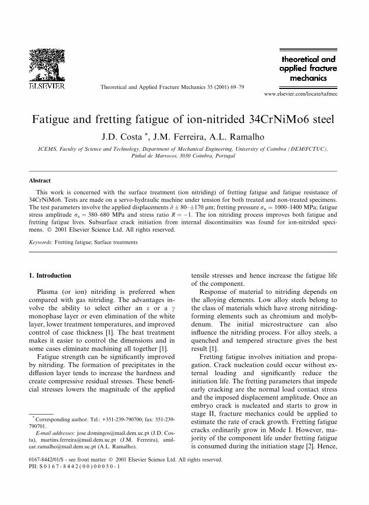
All tests were carried out in tension in a servo-hydraulic machine with load control. Specimendetails are shown in Fig. 1(a). According to theASTM E466-82 standard [11], the specimens weremachined from a bar with 16 mm diameter. Thegeometry of the fretting pads obtained from thesame material is also shown in Fig. 1(b).
Both untreated and treated specimens weresubmitted to fatigue tests to study the e�ect of thesurface modi®cation treatment on the fatigue re-sistance. The results will be presented by the S±Ncurves. These tests were taken under load controlcondition at a frequency of 10 Hz using a sinu-soidal waveform and a stress ratio R of )1. Theload was monitored using a load cell. The numberof cycles up to fracture was taken. Fretting fatiguetests were also conducted for treated and untreated
Table 1
Chemical composition of 34CrNiMo6 steel (%)
C Cr Mn Si Mo Ni Fe
0.34 1.55 0.55 0.27 0.22 1.55 Balance
Table 2
Mechanical properties of 34CrNiMo6 steel
Yield strength (Mpa) Tensile strength (MPa) Elongation to rupture (%) Hardness HV
1100 1250 10 365
Table 3
Nitrogen ion implantation treatment
Temperature (°C) Time (h) White layer Di�usion layer
Hardness (HV0;2) Thickness (lm) Thickness (mm)
530 6 900 10 0.35
70 J.D. Costa et al. / Theoretical and Applied Fracture Mechanics 35 (2001) 69±79
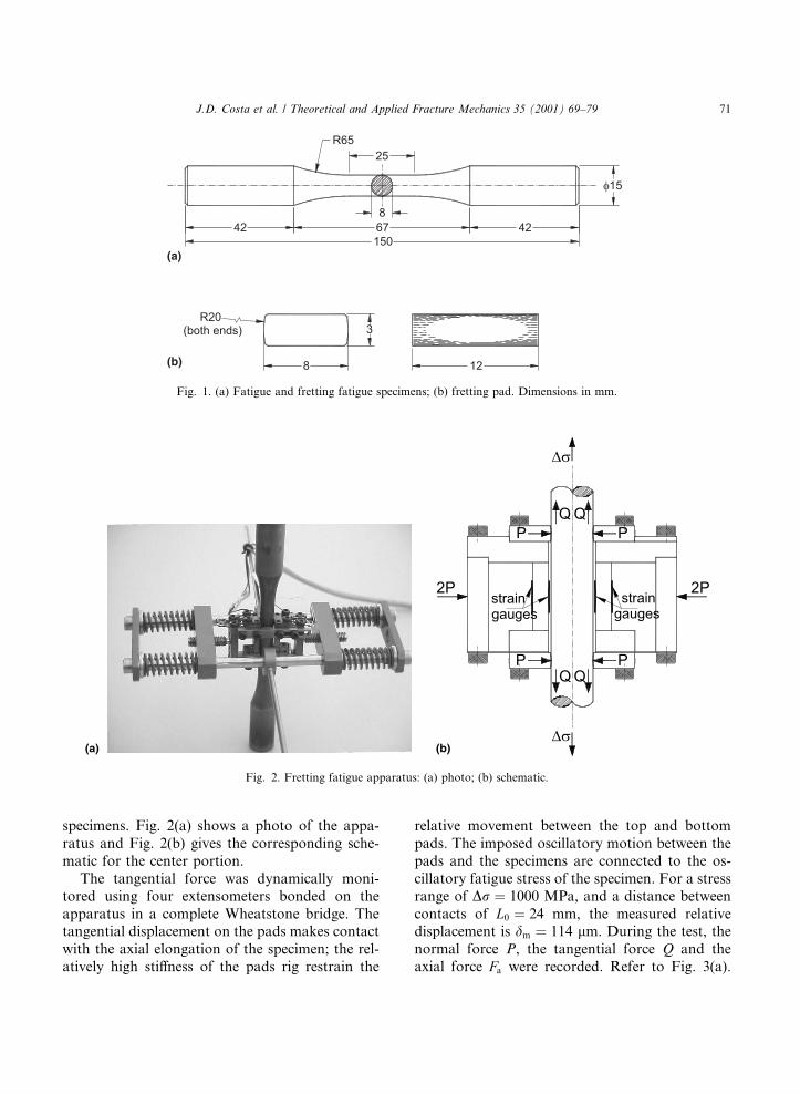
specimens. Fig. 2(a) shows a photo of the appa-ratus and Fig. 2(b) gives the corresponding sche-matic for the center portion.
The tangential force was dynamically moni-tored using four extensometers bonded on theapparatus in a complete Wheatstone bridge. Thetangential displacement on the pads makes contactwith the axial elongation of the specimen; the rel-atively high sti�ness of the pads rig restrain the
relative movement between the top and bottompads. The imposed oscillatory motion between thepads and the specimens are connected to the os-cillatory fatigue stress of the specimen. For a stressrange of Dr � 1000 MPa, and a distance betweencontacts of L0 � 24 mm, the measured relativedisplacement is dm � 114 lm. During the test, thenormal force P, the tangential force Q and theaxial force Fa were recorded. Refer to Fig. 3(a).
Fig. 2. Fretting fatigue apparatus: (a) photo; (b) schematic.
Fig. 1. (a) Fatigue and fretting fatigue specimens; (b) fretting pad. Dimensions in mm.
J.D. Costa et al. / Theoretical and Applied Fracture Mechanics 35 (2001) 69±79 71
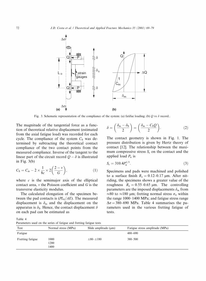
The magnitude of the tangential force as a func-tion of theoretical relative displacement (estimatedfrom the axial fatigue load) was recorded for eachcycle. The compliance of the system CS was de-termined by subtracting the theoretical contactcompliance of the two contact points from themeasured compliance. Inverse of the tangent to thelinear part of the circuit record Qÿ d is illustratedin Fig. 3(b)
CS � Cm ÿ 2� 1
8c� 2
2ÿ mG
� �; �1�
where c is the semimajor axis of the ellipticalcontact area, m the Poisson coe�cient and G is thetransverse elasticity modulus.
The calculated elongation of the specimen be-tween the pad contacts is (PL0=AE). The measureddisplacement is dm and the displacement on theapparatus is dS. Hence, the contact displacement don each pad can be estimated as
d � dm ÿ dS
2
� �� dm ÿ CSQ
2
� �: �2�
The contact geometry is shown in Fig. 1. Thepressure distribution is given by Hertz theory ofcontact [12]. The relationship between the maxi-mum compressive stress Sc on the contact and theapplied load Pn is
Sc � 310:4P 1=3n : �3�
Specimens and pads were machined and polishedto a surface ®nish Ra � 0:12±0:17 lm. After nit-riding, the specimens shows a greater value of theroughness Ra � 0:55±0:65 lm. The controllingparameters are the imposed displacements dm from�80 to �180 lm; fretting normal stress rn withinthe range 1000±1400 MPa; and fatigue stress rangeDr� 380±690 MPa. Table 4 summarises the pa-rameters used in the various fretting fatigue oftests.
Table 4
Parameters used on the series of fatigue and fretting fatigue tests
Test Normal stress (MPa) Slide amplitude (lm) Fatigue stress amplitude (MPa)
Fatigue 480±690
Fretting fatigue 1000 �80±�180 380±500
1200
1400
Fig. 3. Schematic representation of the compliance of the system: (a) fatifue loading; (b) Q vs d record..
72 J.D. Costa et al. / Theoretical and Applied Fracture Mechanics 35 (2001) 69±79

In order to identify the degradation mecha-nisms, the fatigue surfaces were examined byscanning electron microscopy. The tests were madeat room temperature (20°C) and relative humiditybetween 40% and 50%.
3. Results and discussion
Figs. 4(a) and (b) show two photos of the cross-section of the treated specimens. The two typicallayers created by the nitrogen ion implantation canbe clearly seen. The white surface layer is very thin;it has a thickness of about 10 lm. Below this, asecond thicker layer is seen; it is the di�usion layer.The hardening process is obtained by nitrogeninterstitial solution and formation of some phasesby combination with other alloy elements in thesteel. The thickness of the nitrided layer is about0.35 mm.
Fatigue life is normally improved by increasingthe surface hardness with a surface treatment.Vickers microhardness was evaluated at the cross-section of the specimens for both treated and non-treated specimens. The results are plotted in Fig. 5against the distance from the surface. A maximumvalue of hardness of about 900 HV was observednear the surface within the white layer. In thedi�usion layer, the hardness decreases with the
distance from the surface. For depths above0.6 mm, the hardness remains at 365 HV. Themicrohardness measurements were repeated forseveral specimens and no signi®cant di�erenceswere found.
Comparing the hardness of the treated and theuntreated specimens for depths greater than0.60 mm, similar values of about 365 HV wereobserved. There was no decrease of hardness in thetreated specimens. This is possibly caused bytempering that could have occurred during nitro-gen ion implantation. It is important to note thisbecause a lost of hardness in the core of the treated
Fig. 4. Microstructure of the nitrided layers 34CrNiMo6 steel: (a) view of total treated layer; (b) detailed view of the white layer and
microstructure of the di�usion layer.
Fig. 5. Microhardness pro®les for both ion-nitrided and non-
treated specimens.
J.D. Costa et al. / Theoretical and Applied Fracture Mechanics 35 (2001) 69±79 73

specimens could suppress the initiation of a sub-surface crack.
Four series of tests were carried out. Each seriesconsists of more than six tests covering the range104 and 107 cycles. The results are plotted in Fig. 6for untreated and treated specimens. Plotted arethe stress range against the number of cycles tofailure. The treated specimens show a higher fa-tigue resistance than the untreated specimens.
For the same material subjected to bending atR � 0, previous work [13] showed only a slightimprovement of fatigue resistance. For lives below105 cycles, a decrease of fatigue resistance was
observed. This was attributed to the formation ofa very hard white layer that is brittle. Crack ini-tiation was enhanced by cleavage, specially forhigh applied maximum stress with R � 0.
Fig. 7 shows some stabilised loops of the tan-gential force Q versus measured displacement d fordi�erent values of normal pressure Pn and slideamplitude d. Table 5 gives values of the relevantparameters for the specimens referred in Fig. 7.One of these parameters is the energy ratio Ed=Et,where Ed is the energy dissipated during a loadingcycle and Et is the total fretting cycle energy (2Qd),which is one of the criteria used to determine the
Fig. 6. Experimental fatigue results and average S±N curves.
Fig. 7. Hysteresis loops of the tangential force Q versus mea-
sured displacement dm.
Table 5
Test conditions and results of the fretting fatigue tests on the non-treated condition
Ref.
specimen
Dr (MPa) rn (MPa) dm �lm� d �lm� No. of
cycles
Tangent
force, Q �N�Friction
coe�., lEd
�N lm�Et �2dmQ��N lm�
Ed=Et
FF01 964.5 1200 110 43 92 553 51 0.88 7544 11 310 0.667
FF02 992.3 1200 113 44 65 505 48.5 0.84 7448 11 113 0.670
FF03 905.7 1200 103 37 85 543 51.5 0.89 6294 10 736 0.586
FF04 771.6 1200 88 34 252 910 52 0.90 6278 9313 0.674
FF05 984.3 1000 112 48 86 819 32 0.95 5777 7353 0.786
FF06 898.4 1000 103 42 108 794 34.5 1.03 5109 7300 0.700
FF07 774.7 1000 88 37 209 808 32 0.95 4288 5771 0.743
FF08 982.3 1400 112 34 40 850 101 1.10 11 002 23 127 0.476
FF09 771.6 1400 88 19 85 063 95 1.04 4953 16 819 0.295
FF10 771.6 1200 132 54 90 558 47 0.81 9175 12 850 0.714
FF11 765.5 1200 131 54 172 897 47 0.81 9143 12 561 0.728
FF12 776.3 1200 177 73 758 000 56.5 0.97 15 300 20 448 0.748
Average 0.93
Standard deviation 0.09
74 J.D. Costa et al. / Theoretical and Applied Fracture Mechanics 35 (2001) 69±79

regime of fretting [14]. It can be concluded that allthe tests were made in the gross slip regime char-acterised by an energy ratio greater than 0.2. Onlythe FF09 test has an energy ratio of 0.295; it isclose to the mixed stick-slip regime. One conditionfor the existence of the fretting regime is that theratio between the contact amplitude and the lengthof contact in the direction of sliding must be lessthan unity. For the tests in this work, the ratio isbetween 0.07 and 0.3.
Fig. 8 shows the evolution of the friction coef-®cient with the number of cycles. The signi®cantvariation occurred within the ®rst 100 cycles wherea large increase of the friction coe�cient is ob-served. Thereafter, a ¯uctuation is observed. Thesevariations always occur during the ®rst thousandsof cycles. The maximum values of the friction co-e�cient attained in each test are given in Table 5.A reduced scatter can be obtained for a meanvalue of 0.93 with a standard deviation of 0.09.
Results of fretting fatigue of untreated speci-mens are plotted in the Fig. 9. It shows plots of thestress range against the number of cycles to failurefor three normal loads rN. The S±N curves are alsoshown for comparison. Note that fretting fatigueinteraction decreases the resistance of the materialfor the untreated condition. As the normal loadincreases from 1200 to 1400 MPa, the fretting fa-tigue life decreases. This is expected. ForrN � 1000 and 1200 MPa, the fretting fatigue lives
does not change signi®cantly. This behaviour isnot in agreement with the work in [5,15], whichreports the existence of a normal pressure thresh-old for fretting fatigue, above which the pressuredoes not a�ect the fatigue life. The correspondingvalues of pressure in the present tests are themaximum Hertzian compressive stresses. Theyreduce signi®cantly as the area of the contactsurface increase by wear. For typical values ofsurface area observed at the end of the frettingfatigue tests, the pressures were 22, 38 and61 MPa, respectively, for Hertzian maximumstresses of 1000, 1200 and 1400 MPa. Between1000 and 1200 MPa, the variation between the®nal pressures is about 16 MPa. Between 1200 and1400 MPa, the variation is about 23 MPa. Thisexplains, in part, the in¯uence of the normalpressure. The in¯uence however is not consistentand more tests are needed for an explanation.
The values of the exponent on the Basquin re-lation were observed to be very di�erent for thetwo types of tests: )0.088 for the fatigue tests and)0.18 to )0.33 for the fretting fatigue tests. Valuesas high as these obtained in fretting fatigue testsare very close to the inverse of the Paris coe�cientm for steels (m� 4±6). Therefore, crack propaga-tion life is more important in the fretting fatiguetests than that in the plain fatigue tests. The ini-tiation phase occupies only a small part of thespecimen life.
Fig. 8. Variation of the friction coe�cient with the number of
cycles (rn � 1200 MPa; dm � 131 lm).
Fig. 9. Experimental fretting fatigue results for the non-treated
condition.
J.D. Costa et al. / Theoretical and Applied Fracture Mechanics 35 (2001) 69±79 75
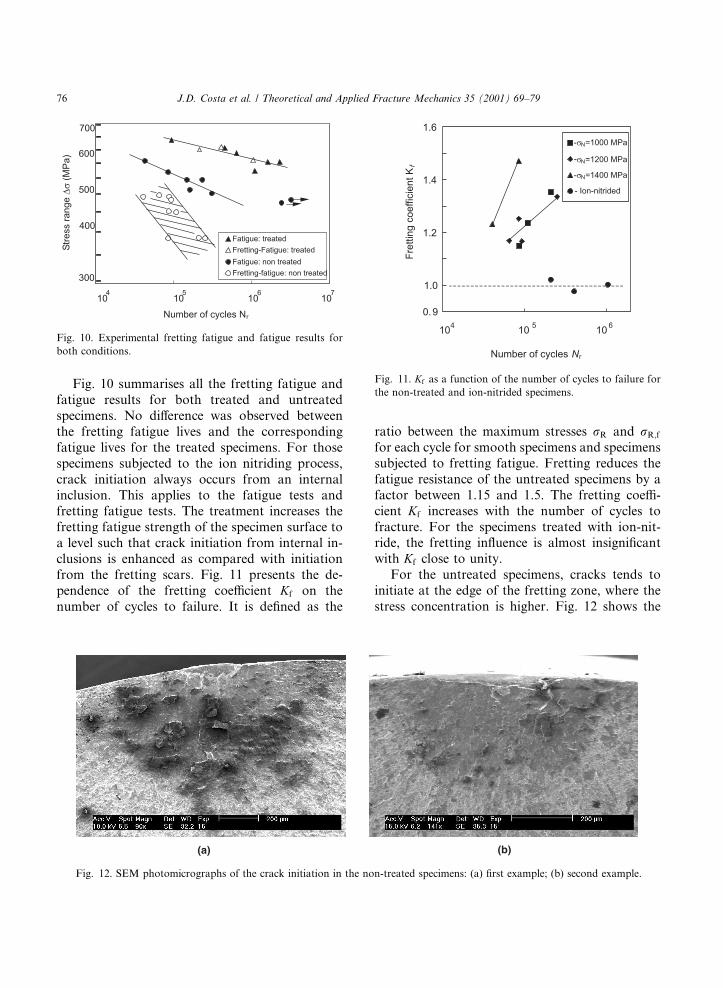
Fig. 10 summarises all the fretting fatigue andfatigue results for both treated and untreatedspecimens. No di�erence was observed betweenthe fretting fatigue lives and the correspondingfatigue lives for the treated specimens. For thosespecimens subjected to the ion nitriding process,crack initiation always occurs from an internalinclusion. This applies to the fatigue tests andfretting fatigue tests. The treatment increases thefretting fatigue strength of the specimen surface toa level such that crack initiation from internal in-clusions is enhanced as compared with initiationfrom the fretting scars. Fig. 11 presents the de-pendence of the fretting coe�cient Kf on thenumber of cycles to failure. It is de®ned as the
ratio between the maximum stresses rR and rR;f
for each cycle for smooth specimens and specimenssubjected to fretting fatigue. Fretting reduces thefatigue resistance of the untreated specimens by afactor between 1.15 and 1.5. The fretting coe�-cient Kf increases with the number of cycles tofracture. For the specimens treated with ion-nit-ride, the fretting in¯uence is almost insigni®cantwith Kf close to unity.
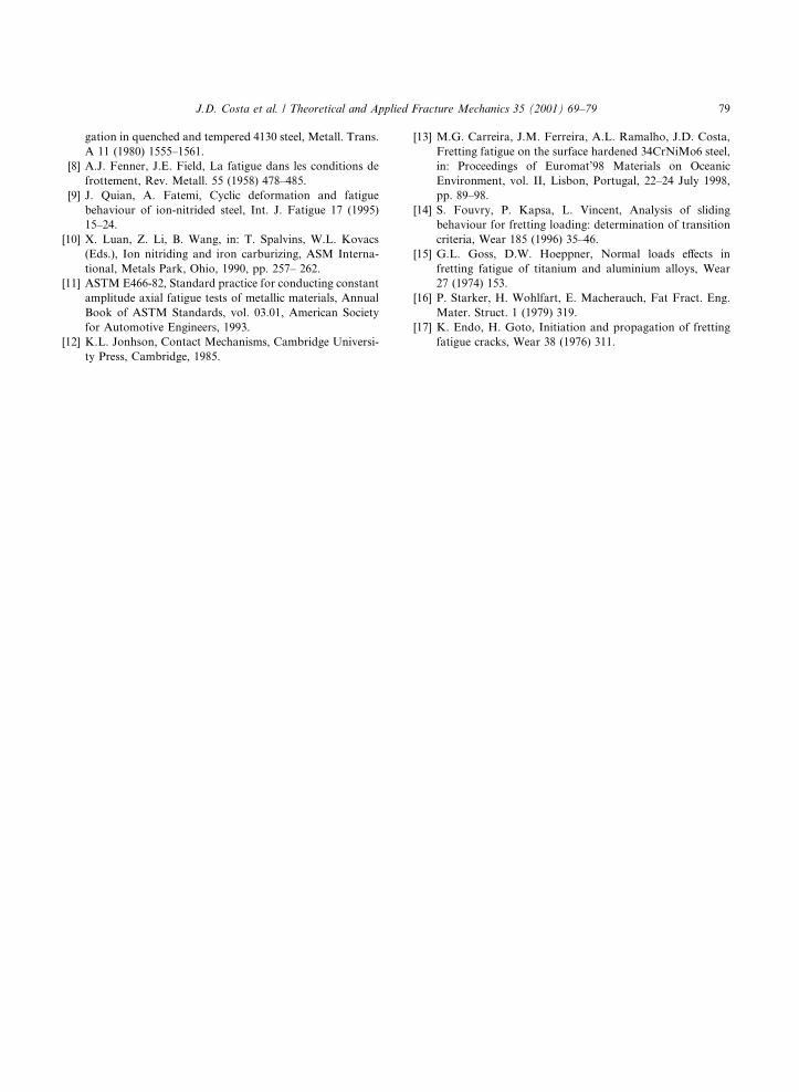
For the untreated specimens, cracks tends toinitiate at the edge of the fretting zone, where thestress concentration is higher. Fig. 12 shows the
Fig. 10. Experimental fretting fatigue and fatigue results for
both conditions.
Fig. 11. Kf as a function of the number of cycles to failure for
the non-treated and ion-nitrided specimens.
Fig. 12. SEM photomicrographs of the crack initiation in the non-treated specimens: (a) ®rst example; (b) second example.
76 J.D. Costa et al. / Theoretical and Applied Fracture Mechanics 35 (2001) 69±79

results of two examples. Debris of oxidation canbe observed on the fatigue surfaces. Formed arethe fretting scars that are probably transported tothe fatigue surfaces by the slide movement betweenthe pad and the specimen. For the specimens withion nitride, crack is always initiated below thesurface, starting from an inclusion, not only forthe fatigue tests but also for the fretting fatiguetests. Figs. 13(a)±(c) present three typical examplesof the photomicrographs obtained by scanningelectron microscopy. Fig. 13(d) gives a detailedview of crack initiation from an inclusion. For a
homogeneous material, the process of fatigue ini-tiation usually starts from a free surface followingthe intrusion and extrusion mechanism producedby sequential slip of two intersecting slip planes.However, in specimen treated by ion-nitride, thisprocess is impeded by the increased hardness ofthe surface layer. As a consequence, cracks caninitiate easier from internal discontinuities. Manyinvestigators have shown that subsurface crackinitiation is associated with non-metallic inclusions[16]. Although measurements of residual stresseswere not carried out in this work, their presence is
Fig. 13. SEM photomicrographs of crack initiation at inclusions in the ion-nitrided specimens. White arrows indicate origin of the
crack initiation: (a) rmax � 602 MPa; Nf � 1; 620; 630; (b) rmax � 687 MPa; Nf � 94; 600; (c) rmax � 572 MPa; Nf � 1; 098; 200;
(d) detailed view of photomicrograph (a).
J.D. Costa et al. / Theoretical and Applied Fracture Mechanics 35 (2001) 69±79 77

expected during the ion-nitriding treatment. Theformation of nitrides in a layer could cause avolume increase. This is restrained by the corecausing a state of compression and tensile in thecore. The action of compression tends to reducethe tensile action in fatigue.
Investigators [6,17] have used a combination ofapplied fatigue stress, frictional tangential stressand normal pressure as fretting fatigue parame-ters. They consider these as the cause of damagethat lead to eventual to nucleation and propaga-tion of fatigue cracks. Models have been proposedto suggest that tangential stress increases with thenormal pressure. This would cause a decrease inthe fretting fatigue life of the components. Thepossible existence of the pressure threshold tendsto limit the application of these models. One ofthese models will be used. Fig. 14 shows the re-sults, where the empirical parameter Drsd is plot-ted against the number of cycles to failure. Here,Dr is the fatigue stress range, s the tangential stressand d is the slide displacement on the contact.Despite the scatter, a decreasing trend of the Drsdparameter with increasing Nr is clear.
4. Conclusions
· The process of ion nitriding improves fatigue re-sistance of the 34CrNiMo6 steel in the range oflives analysed. The treatment increases the hard-
ness of the surface layer and introduces com-pressive residual stress preventing crackinitiation in the surface layer. As a consequence,crack initiation occurs from internal discontinu-ities for applied stresses higher than those of theuntreated specimens. This explanation is sup-ported by SEM of the fatigue surfaces.
· Fretting fatigue lives of untreated specimenswere signi®cantly lower than those specimenstreated with ion nitride. Crack initiation in thefretting fatigue of specimens treated with ion-nitride also occurs from internal discontinuities.Hence, fretting damage does not seem to in¯u-ence the life of the specimen.
· An in¯uence of the normal pressure was ob-served between 1200 and 1400 MPa. However,for the lower values of the stress range 1000±1200 MPa, the fretting fatigue values are veryclose. More tests are needed before a conclusioncould be made in the in¯uence of normal stress.
Acknowledgements
The present work has been supported by thePortuguese Government Project Praxis XXI 2/2.1TPAR 2041/95. It is very important for us that thislast modi®cation can be considered. We want totanks in advance.
References
[1] M. James, O. Brien, D. Goodman, Plasma (Ion) Nitriding,
ASM International, Metals Park, OH, 1995, pp. 420±424.
[2] D.A. Hiils, D. Nowell, J.J. O'Connor, On the mechanics of
fretting fatigue, Wear 125 (1988) 129±146.
[3] C. Petiot, L. Vincent, K. Dang Van, N. Maouche,
J. Foulquier, B. Journet, An analysis of fretting fatigue
failure combined with numerical calculations to predict
crack nucleation, Wear 181±183 (1995) 101±111.
[4] O. Vingsbo, D. Soderberg, On fretting maps, Wear 126
(1988) 131±147.
[5] S. Adibnazari, D. Hoepper, A fretting fatigue normal
pressure threshold concept, Wear 160 (1993) 33±35.
[6] M.H. Wharton, R.B. Waterhouse, The e�ect of di�erent
contact materials on the fretting fatigue strength of an
aluminium alloy, Wear 26 (1973) 253.
[7] D.J. Gaul, D.J. Duquette, The e�ect of fretting and
environment on fatigue crack initiation and early propa-
Fig. 14. Fretting fatigue parameter Drsd against the number of
cycles to failure.
78 J.D. Costa et al. / Theoretical and Applied Fracture Mechanics 35 (2001) 69±79
gation in quenched and tempered 4130 steel, Metall. Trans.
A 11 (1980) 1555±1561.
[8] A.J. Fenner, J.E. Field, La fatigue dans les conditions de
frottement, Rev. Metall. 55 (1958) 478±485.
[9] J. Quian, A. Fatemi, Cyclic deformation and fatigue
behaviour of ion-nitrided steel, Int. J. Fatigue 17 (1995)
15±24.
[10] X. Luan, Z. Li, B. Wang, in: T. Spalvins, W.L. Kovacs
(Eds.), Ion nitriding and iron carburizing, ASM Interna-
tional, Metals Park, Ohio, 1990, pp. 257± 262.
[11] ASTM E466-82, Standard practice for conducting constant
amplitude axial fatigue tests of metallic materials, Annual
Book of ASTM Standards, vol. 03.01, American Society
for Automotive Engineers, 1993.
[12] K.L. Jonhson, Contact Mechanisms, Cambridge Universi-
ty Press, Cambridge, 1985.
[13] M.G. Carreira, J.M. Ferreira, A.L. Ramalho, J.D. Costa,
Fretting fatigue on the surface hardened 34CrNiMo6 steel,
in: Proceedings of Euromat'98 Materials on Oceanic
Environment, vol. II, Lisbon, Portugal, 22±24 July 1998,
pp. 89±98.
[14] S. Fouvry, P. Kapsa, L. Vincent, Analysis of sliding
behaviour for fretting loading: determination of transition
criteria, Wear 185 (1996) 35±46.
[15] G.L. Goss, D.W. Hoeppner, Normal loads e�ects in
fretting fatigue of titanium and aluminium alloys, Wear
27 (1974) 153.
[16] P. Starker, H. Wohlfart, E. Macherauch, Fat Fract. Eng.
Mater. Struct. 1 (1979) 319.
[17] K. Endo, H. Goto, Initiation and propagation of fretting
fatigue cracks, Wear 38 (1976) 311.
J.D. Costa et al. / Theoretical and Applied Fracture Mechanics 35 (2001) 69±79 79