
FASTENER OF EXTERNAL WALL CLADDINGS
31
EAD 330030-00-0601 August 2018 FASTENER OF EXTERNAL WALL CLADDINGS ©2018
Transcript of FASTENER OF EXTERNAL WALL CLADDINGS

EAD 330030-00-0601
August 2018
FASTENER OF EXTERNAL WALL CLADDINGS
©2018

European Assessment Document – EAD 330030-00-0601 2/31
©EOTA 2018
The reference title and language for this EAD is English. The applicable rules of copyright refer to the document elaborated in and
published by EOTA.
This European Assessment Document (EAD) has been developed taking into account up-to-date technical and scientific knowledge
at the time of issue and is published in accordance with the relevant provisions of Regulation (EU) No 305/2011 as a basis for the
preparation and issuing of European Technical Assessments (ETA).
European Assessment Document – EAD 330030-00-0601 3/31
©EOTA 2018
Contents
1 Scope of the EAD ................................................................................................................................ 4
1.1 Description of the construction product ............................................................................................ 4
1.2 Information on the intended use of the construction product ........................................................... 5
1.2.1 Intended use ................................................................................................................................ 5 1.2.2 Working life/Durability .................................................................................................................. 6
1.3 Specific terms used in this EAD ....................................................................................................... 7
1.3.1 General ........................................................................................................................................ 7 1.3.2 Notations ...................................................................................................................................... 7
2 Essential characteristics and relevant assessment methods and criteria ................................... 9
2.1 Essential characteristics of the product ............................................................................................ 9
2.2 Methods and criteria for assessing the performance of the product in relation to essential characteristics of the product .......................................................................................................... 10
2.2.1 Characteristic resistance to breakout or pull-out failure under tension load ............................. 10 2.2.2 Characteristic resistance to breakout or pull-out failure under shear load ................................ 11 2.2.3 Characteristic resistance to breakout or pull-out failure under combined tension and shear
load ............................................................................................................................................ 11 2.2.4 Edge distances and spacing...................................................................................................... 13 2.2.5 Durability .................................................................................................................................... 14 2.2.6 Characteristic resistance to steel failure under tension and shear load .................................... 14 2.2.7 Reaction to fire .......................................................................................................................... 14
3 Assessment and verification of constancy of performance ........................................................ 15
3.1 System of assessment and verification of constancy of performance to be applied ...................... 15
3.2 Tasks of the manufacturer .............................................................................................................. 15
3.3 Tasks of the notified body ............................................................................................................... 16
4 Reference documents ...................................................................................................................... 17
Annex A Test program and details of tests ..................................................................................... 18
Annex B General Assessment methods .......................................................................................... 29
European Assessment Document – EAD 330030-00-0601 4/31
©EOTA 2018
1 SCOPE OF THE EAD
1.1 Description of the construction product
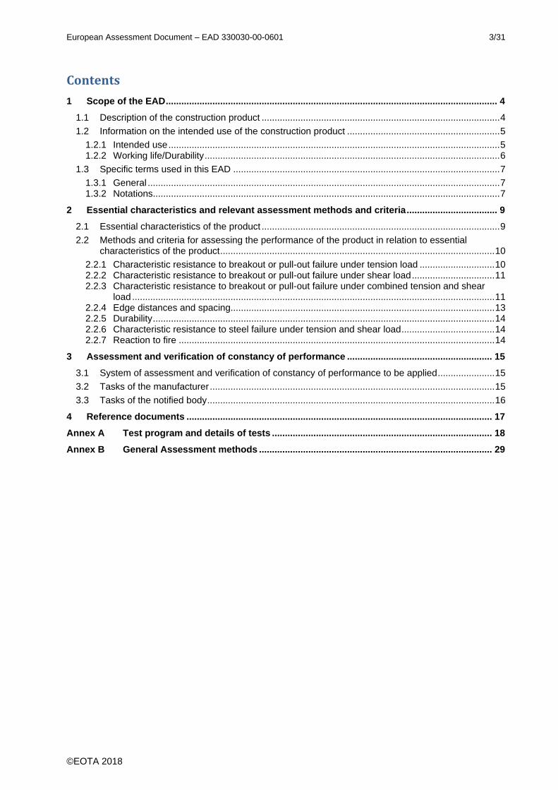
This EAD covers the special fasteners for rear fixing of façade panels in external wall claddings. The load-bearing parts of the fastener are made of stainless steel. The fastener is placed in a drill hole or in an undercut hole in the façade panel and anchored deformation controlled or torque-controlled by mechanical interlock. Examples of the installed product are given in Figure 1.1.
Figure 1.1 Examples of installed product
This EAD covers stand-off fasteners only when the clamp does not touch the panel in case of panel bending. The relevant angle is part of the product description.
The façade panel, the clamp, the subframe components and any other façade system component is not covered by this EAD.
The product is not covered by a harmonised European standard (hEN).
Concerning product packaging, transport, storage, maintenance, replacement and repair it is the responsibility of the manufacturer to undertake the appropriate measures and to advise his clients on the transport, storage, maintenance, replacement and repair of the product as he considers necessary.
It is assumed that the product will be installed according to the manufacturer’s instructions or (in absence of such instructions) according to the usual practice of the building professionals.
Relevant manufacturer’s stipulations having influence on the performance of the product covered by this European Assessment Document shall be considered for the determination of the performance and detailed in the ETA.
fastener fastener
clamp clamp façade panel
European Assessment Document – EAD 330030-00-0601 5/31
©EOTA 2018
1.2 Information on the intended use of the construction product
1.2.1 Intended use
The fastener is intended to be used for the fixing of façade panels from their back side. The façade panels are used as external ventilated wall claddings. The fastener is intended to be used for fixing panels in vertical or horizontal position. Every façade panel is fixed with at least four fasteners placed in a rectangular pattern.
The fastener is intended to be used in façade panels made of the following materials:
Mineral bonded panels:
- Natural stone according to EN 1469 [1],
- Cast stone,
- Ceramic tiles, e. g. according to EN 14411 [2],
- Glass ceramic,
- Fibre cement flat sheets according to EN 12467 [4],
- Polymer concrete (mineral cast),
Resin bonded or plastic bonded panels:
- High-pressure decorative laminates (HPL) according to EN 438-7 [3],
- Polymethylmethacrylate (PMMA),
- Glass reinforced fibre concrete (GFRC),
- Ultra High Performance Concrete (UHPC).
The panel material is specified by its flexural strength 5% (5%-fractile value of ≥ 5 tests on panels by using a lognormal distribution, a confidence level of 75% and a unknown standard deviation) and by its E-Modulus Em (mean value of ≥ 5 tests on panels). For natural stone material these values based on tests according to EN 12372 [11].
Façade panels made of natural stone additional specified by a geo-scientific (petrographic) determination and evidence is available that for each individual deposit of the relevant batch used (in the dimension of the batch needed) that it is free of open seams and mechanically active cracks and alterations.
For fasteners in natural stone panels the specific natural stone material, which is tested and assessed, is given in the ETA (trade name and country of origin according to EN 12440 [12]).
Façade panels made of natural stone are divided into different Stone groups according to following Table.
Table 1.1 Stone groups for façade panels made of natural stone
Stone group Natural stone type Boundary conditions
I High quality intrusive rocks
(plutonic rocks)
Granite, granitite, tonalite, diorite, monzonite, gabbro,
other magmatic plutonic rocks None
II Metamorphic rocks with
„hard stone characteristics“ Quarzite, granulite, gneiss,
migmatite, slate 2) None
III High quality extrusive rocks
(volcanic rocks)
Basalt and basaltic lava without harmful ingredients
(like sun burner basalt)
Minimum density ρ: basalt: 2,7 kg/dm³
basaltic lava: 2,2 kg/dm³
IV Sedimentary rocks with
„hard stone characteristics“1) Sandstone, limestone
and marble Minimum density ρ:
sandstone: 2,1 kg/dm³
1) For façade panels made of natural stones with planes of anisotropies, the difference between the flexural strength determined parallel to the planes of anisotropy and perpendicular to the edges of the planes of anisotropy shall not be more than 50 %.
2) This EAD only covers fasteners used for slate panels with a mean value of tensile bond strength larger than 0,5 N/mm2 and the minimum value of tensile bond strength larger than 0,25 N/mm2
European Assessment Document – EAD 330030-00-0601 6/31
©EOTA 2018
The fastener is intended to be used with a minimum edge distance of 50 mm.
The fastener is intended to be used under static and quasi-static actions.
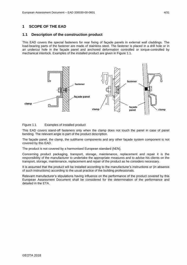
The façade panels are fixed free of strains to a substructure (see Figure 1.2).
Verification of stability of the clamp, the panel and the substructure including its fixing with wall fasteners and their anchorage in the construction works as well as verification of stability of the fixing of any thermal insulation material used are not subject of this EAD.
Figure 1.2 Example of façade panel on substructure
The fasteners in façade panels made of natural stone (except slate) according to EN 1469 [1] are intended to be used for fastenings which are designed according to EOTA TR 062 [5].
According to the manufacturer's installation instructions for the 1 % of all drillings the geometry of the drill hole is to be checked, verified and documented.
Note: The test program and the assessment method included in this EAD are based on the assumption that manufacturer's installation instructions are strictly followed.
The intended use of the fastener regarding environmental conditions results from its corrosion resistance class (CRC) according to EN 1993-1-4 [6].
1.2.2 Working life/Durability
The assessment methods included or referred to in this EAD have been written based on the manufacturer’s request to take into account a working life of the fastener for the intended use of 50 years when installed in the works (provided that the fastener is subject to appropriate installation (see 1.1). These provisions are based upon the current state of the art and the available knowledge and experience.
When assessing the product, the intended use as foreseen by the manufacturer shall be taken into account. The real working life may be, in normal use conditions, considerably longer without major
degradation affecting the basic requirements for works1.
The indications given as to the working life of the construction product cannot be interpreted as a guarantee neither given by the product manufacturer or his representative nor by EOTA when drafting this EAD nor by the Technical Assessment Body issuing an ETA based on this EAD, but are regarded only as a means for expressing the expected economically reasonable working life of the product.
1 The real working life of a product incorporated in a specific works depends on the environmental conditions to which that
works is subject, as well as on the particular conditions of the design, execution, use and maintenance of that works.
Therefore, it cannot be excluded that in certain cases the real working life of the product may also be shorter than referred to
above.
substructure
clamp
European Assessment Document – EAD 330030-00-0601 7/31
©EOTA 2018
1.3 Specific terms used in this EAD
1.3.1 General
Façade panels = panels used for external wall claddings ventilated at rear
Fastener = product for fixing the façade panel to the substructure
1.3.2 Notations
The notations and symbols frequently used in this EAD are given below. Further particular notation and symbols are given in the text.
a = spacing of fasteners
As = stressed cross section of steel element (smallest cross section in the area of load transfer applies)
ar = edge distance of the fastener
arH , arL = edge distance of the fastener based in the height or on the length of the panel
ar,min = minimum edge distance
d0 = diameter of drill hole
d1 = diameter of undercut
d0,m = medium drill hole diameter (within the tolerances, given by the manufacturer)
d0,max = maximum drill hole diameter (given by the manufacturer)
dcut,m = medium drilling diameter (within the tolerances, given by the manufacturer)
dcut,max = maximum drilling diameter (given by the manufacturer)
df = clearance hole
ds = fastener diameter
dsup = diameter of support
fuk = nominal characteristic steel ultimate strength
fu,test = steel ultimate strength at a test
f = conversion factor of façade panel
F = force in general
Fln5% = 5%-logarithmic-fractile of the ultimate load calculated by the logarithmic test values
FrRu = ultimate load in reference tests
FRum = mean value of ultimate loads
FRu,m ln(x) = mean-value of ultimate load in a test series calculated by the logarithmic test
values
FtRu = ultimate load in a test series
Fu = failure load in a test series
Fu,5% = 5% fractile of the failure load Fu
h = hnom = nominal thickness of façade panel
h1 = depth of drill hole
hs = embedment depth of the fastener
ks = statistical factor
Ls = fastener length
n = number of tests
N = normal force
NEd = design fastener value of action under tension load
NRd = design fastener value to breakout or pull-out failure under tension load
NRk = characteristic fastener resistance to breakout or pull-out failure under tension load
NRk,s = characteristic fastener resistance to steel failure under tension load
sln(x) = standard deviation calculated by the logarithmic test values
tfix = thickness of clamp material
Tinst = installation torque

European Assessment Document – EAD 330030-00-0601 8/31
©EOTA 2018
V = shear force
VEd = design fastener value of action under shear load
VRd = design fastener value to breakout or pull-out failure under and shear load
VRk = characteristic fastener resistance to breakout or pull-out failure under and shear load
VRk,s = characteristic fastener resistance to steel failure under and shear load
vu = coefficient of variation of ultimate load of tests
X = limit value in a trilinear function
Y = exponent in an exponential function
α = reduction factor
req α = required reduction factor
α1 = reduction factor for load/displacement ratio
α2,Fi = reduction factor of the functioning tests Fi
αa = reduction factor to consider the maximum spacing
αd = reduction factor to consider the maximum support rotation
αp = reduction factor to consider the applied repeated or sustained load
αv = reduction factor to consider the variation of the ultimate loads in the tests
β = angle of the force to the facade plate
= angle of support rotation
ρ = density
5% = flexural strength of façade panel: 5%-fractile of at least 5 tests by using a confidence level of 75% and an unknown standard deviation and a lognormal distribution
Rum = mean value of tensile bond strength
Ru,min = minimum value of tensile bond strength
European Assessment Document – EAD 330030-00-0601 9/31
©EOTA 2018
2 ESSENTIAL CHARACTERISTICS AND RELEVANT ASSESSMENT METHODS AND CRITERIA
2.1 Essential characteristics of the product
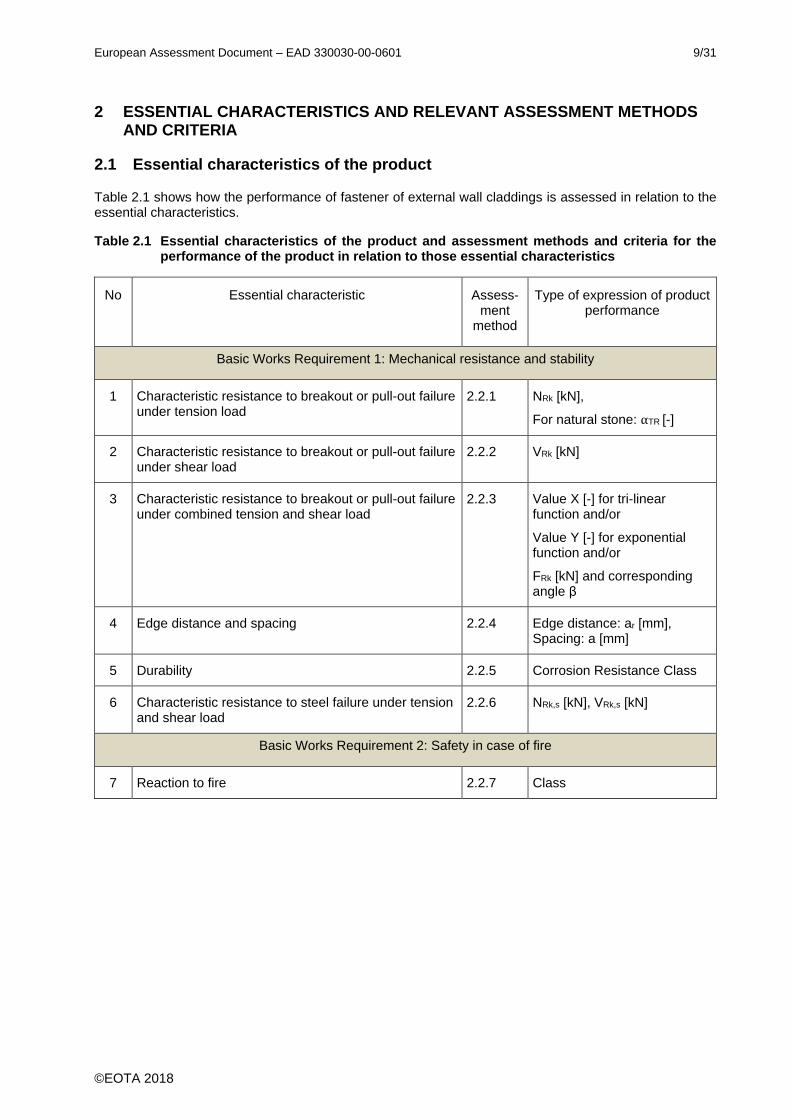
Table 2.1 shows how the performance of fastener of external wall claddings is assessed in relation to the essential characteristics.
Table 2.1 Essential characteristics of the product and assessment methods and criteria for the performance of the product in relation to those essential characteristics
No Essential characteristic Assess-ment
method
Type of expression of product performance
Basic Works Requirement 1: Mechanical resistance and stability
1 Characteristic resistance to breakout or pull-out failure under tension load
2.2.1 NRk [kN],
For natural stone: αTR [-]
2 Characteristic resistance to breakout or pull-out failure under shear load
2.2.2 VRk [kN]
3 Characteristic resistance to breakout or pull-out failure under combined tension and shear load
2.2.3 Value X [-] for tri-linear function and/or
Value Y [-] for exponential function and/or
FRk [kN] and corresponding angle β
4 Edge distance and spacing 2.2.4 Edge distance: ar [mm], Spacing: a [mm]
5 Durability 2.2.5 Corrosion Resistance Class
6 Characteristic resistance to steel failure under tension and shear load
2.2.6 NRk,s [kN], VRk,s [kN]
Basic Works Requirement 2: Safety in case of fire
7 Reaction to fire 2.2.7 Class
European Assessment Document – EAD 330030-00-0601 10/31
©EOTA 2018
2.2 Methods and criteria for assessing the performance of the product in relation to essential characteristics of the product
An overview of the test program for the assessment of the essential characteristics of the product is given in Annex A. Provisions valid for all tests are also given in Annex A. General aspects of the assessment are given in Annex B.
2.2.1 Characteristic resistance to breakout or pull-out failure under tension load
The characteristic resistances to pull-out failure of single fasteners under tension loading shall be calculated as follows:
NRk,0 = f • min Nln5% (2.1)
α2,F = α2,F1 • α2,F2 • α2,F3 • min α2,F4/F5 • min α2,F6a/F6b • α2,F7 (2.2)
NRk = NRk,0 • α1 • α2,F • αv • αp • αa • αd (2.3)
with: min Nln5% = 5%-logarithmic fractile of the ultimate load calculated by the logarithmic test values (according to B.3) of test series A1a and A1c according to Table A.1
f = conversion factor if the flexural strength of the panel used for tests is higher than the value given in the intended use of the ETA (according to B.1)
α2,F = reduction factor of all tests F1 to F7
α2,F1 = reduction factor (according to B.4) resulting from test series F1 (influence of tolerances)
α2,F2 = reduction factor (according to B.4) resulting from the test series F2 (influence of repeated loads)
α2,F3 = reduction factor (according to B.4) resulting from the test series F3 (influence of sustained loads)
min α2,F4/F5 = minimum reduction factor (according to B.4) resulting from the test series F4 (influence of freeze-thaw cycles) and F5 (influence of immersion in water)
min α2,F6a/F6b = reduction factor (according to B.4) resulting from the test series F6a (influence of maximum long-term temperature) and F6b (influence of maximum short term temperature)
α2,F7 = reduction factor for PMMA only (according to B.4) resulting from the test series F7 (influence of UV aging)
α1 = minimum value α1 (according to B.5) of all tension test series (influence of load/displacement behaviour)
αv = minimum value αv (according to B.2) of all test series (influence of the scatter of test results)
αp = minimum value αp (according to B.6) resulting from the test series F2 and F3 (influence of the applied load during repeated load tests or sustained load tests)
αa = Reduction factor for maximum spacing according to 2.2.4 (influence of flexural strength at the panel in the area of the fastener)
αd = Reduction factor for maximum support rotation according to B.7 (influence of support rotation at the panel in the area of the fastener)
For natural stone the reduction factor αTR according to following Equation shall be given in the ETA:
αTR = α2,F1 • α2,F2 • α1 • αv • αa• αp• αd (2.4)

European Assessment Document – EAD 330030-00-0601 11/31
©EOTA 2018
2.2.2 Characteristic resistance to breakout or pull-out failure under shear load
The characteristic resistances of single fasteners under shear loading shall be calculated as follows:
VRk,0 = f • min Vln5% (2.5)
α2,F = α2,F1 • α2,F2 • α2,F3 • min α2,F4/F5 • min α2,F6a/F6b • α2,F7 (2.6)
VRk = VRk,0 • α1 • α2,F • αv • αp • αa (2.7)
with: min Vln5% = 5%-logarithmic fractile of the ultimate load calculated by the logarithmic test values (according to B.3) of test series A2a and A2b according to Table A.1
fα2, α2,F1, α2,F2, α2,F3, min α2,F4/F5, min α2,F6a/F6b, α2,F7, α1, αv, αp, αa see Equation (2.1) to (2.3)
2.2.3 Characteristic resistance to breakout or pull-out failure under combined tension and shear load
Note: For combined tension and shear load the following Equations shall be verified during design:
𝑁𝐸𝑑
𝑁𝑅𝑑
+ 𝑉𝐸𝑑
𝑉𝑅𝑑
≤ X or (2.8)
( 𝑁𝐸𝑑
𝑁𝑅𝑑
)Y+(
𝑉𝐸𝑑
𝑉𝑅𝑑
)Y ≤ 1,0 (2.9)
with: NEd = design value of action under tension loading
NRd = design resistance of the fastener under tension loading
VEd = design value of action under shear loading
VRd = design resistance of the fastener under shear loading
X = limit value in a trilinear function
Y = Exponent in an exponential function
If no tests are performed the value X and Y is 1,0.
If tests (test series A3 according to Table A.1) are performed the values X is assessed as follows:
𝑁𝑅𝑢𝑚,𝐴3𝑡 = 𝐹𝑅𝑢𝑚,𝐴3
𝑡 • sin β (2.10)
𝑉𝑅𝑢𝑚,𝐴3𝑡 = 𝐹𝑅𝑢𝑚,𝐴3
𝑡 • cos β (2.11)
𝑁𝑅𝑢𝑚,𝐴3𝑡
𝑁𝑅𝑢𝑚,𝐴1𝑎𝑟 +
𝑉𝑅𝑢𝑚,𝐴3𝑡
𝑉𝑅𝑢𝑚,𝐴2𝑎𝑟 = XH (2.12)
For XH < 1,2: X = 1,0
For XH ≥ 1,2: X = 1,2
For XH ≥ 1,3 for steel failure: X = 1,3
with:
𝐹𝑅𝑢𝑚,𝐴3𝑡 = mean value of failure load of tests A3 according to Table A.1
𝑁𝑅𝑢𝑚,𝐴3𝑡 = mean value of tension load from the failure load of tests A3 according to Table A.1
𝑉𝑅𝑢𝑚,𝐴3𝑡 = mean value of shear load from the failure load of tests A3 according to Table A1
β = angle in tests A3 according to Table A.1
𝑁𝑅𝑢𝑚,𝐴1𝑎𝑟 = mean value of failure loads in the reference tests A1a according to Table A.1
𝑉𝑅𝑢𝑚,𝐴2𝑎𝑟 = mean value of failure loads in the reference tests A2a according to Table A.1
European Assessment Document – EAD 330030-00-0601 12/31
©EOTA 2018
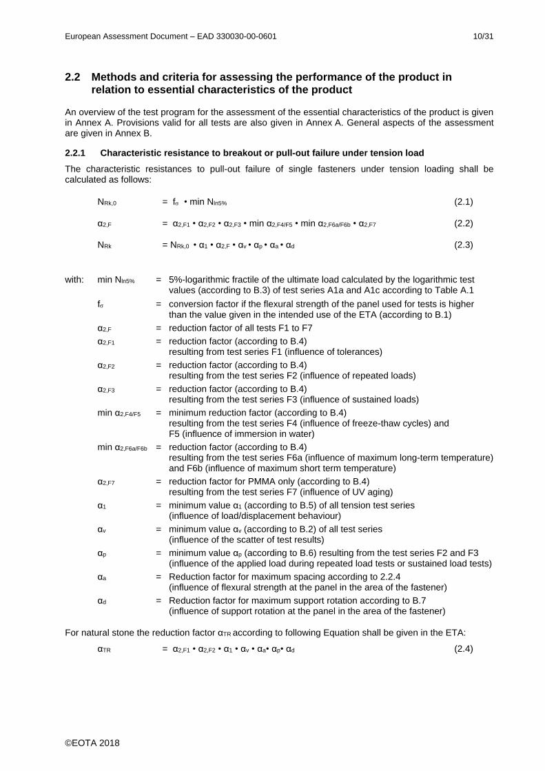
If tests (test series A3 according to Table A.1) are performed the values Y is assessed as follows:
(𝑁𝑅𝑢𝑚,𝐴3
𝑡
𝑁𝑅𝑢𝑚,𝐴1𝑎𝑟 )
1,5
+ (𝑉𝑅𝑢𝑚,𝐴3
𝑡
𝑉𝑅𝑢𝑚,𝐴2𝑎𝑟 )
1,5
= YH,1,5 (2.13)
For YH,1,5 < 1,0: Y = 1,0
For YH,1,5 ≥ 1,0: Y = 1,5
Only for steel failure:
(𝑁𝑅𝑢𝑚,𝐴3
𝑡
𝑁𝑅𝑢𝑚,𝐴1𝑎𝑟 )
2,0
+ (𝑉𝑅𝑢𝑚,𝐴3
𝑡
𝑉𝑅𝑢𝑚,𝐴2𝑎𝑟 )
2,0
= YH,2,0 (2.14)
For YH,2,0 ≥ 1,0: Y = 2,0
with:
𝑁𝑅𝑢𝑚,𝐴3𝑡 = mean value of tension load from the failure load of tests A3 according to Table A.1
𝑉𝑅𝑢𝑚,𝐴3𝑡 = mean value of shear load from the failure load of tests A3 according to Table A1
𝑁𝑅𝑢𝑚,𝐴1𝑎𝑟 = mean value of failure loads in the reference tests A1a according to Table A.1
𝑉𝑅𝑢𝑚,𝐴2𝑎𝑟 = mean value of failure loads in the reference tests A2a according to Table A.1
Figure 2.1 Interaction diagram for combined tension and shear loads
Additional the characteristic resistances of single fasteners under combined tension and shear loading for the tested angle β can be calculated as follows:
FRk,0 = f • Fln5% (2.15)
FRk = FRk,0 • α1 • α2,F • αv • αp • αa • αd (2.16)
with: Fln5% = 5%-logarithmic fractile of the ultimate load calculated by the logarithmic test values (according to B.3) of test series A3 according to Table A.1
f α1, α2,F, αv, αp, αa, αd see Equation (2.1) to (2.3)
𝑉𝑅𝑢𝑚,𝐴3𝑡
𝑉𝑅𝑢𝑚,𝐴2𝑎𝑟
(2.14) with Y = 2,0
(2.13) with Y = 1,5
(2.12) with X =1,2
(2.12) with X =1,3
𝑁𝑅𝑢𝑚,𝐴3𝑡
𝑁𝑅𝑢𝑚,𝐴1𝑎𝑟
European Assessment Document – EAD 330030-00-0601 13/31
©EOTA 2018
2.2.4 Edge distances and spacing
For minimum edge distances smaller than 100 mm the minimum edge distance corresponds to the minimum edge distances in test series A1c according to Table A1:
arH = arL = ar,min ≥ 50 mm
The minimum spacing is 8 hs.
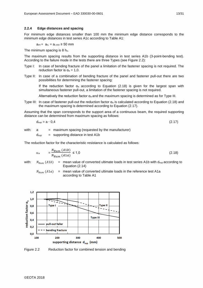
The maximum spacing results from the supporting distance in test series A1b (3-point-bending test). According to the failure mode in the tests there are three Types (see Figure 2.2):
Type I: In case of bending fracture of the panel a limitation of the fastener spacing is not required. The reduction factor is αa = 1,0.
Type II: In case of a combination of bending fracture of the panel and fastener pull-out there are two possibilities for determining the fastener spacing:
If the reduction factor αa according to Equation (2.18) is given for the largest span with simultaneous fastener pull-out, a limitation of the fastener spacing is not required.
Alternatively the reduction factor αa and the maximum spacing is determined as for Type III.
Type III: In case of fastener pull-out the reduction factor αa is calculated according to Equation (2.18) and the maximum spacing is determined according to Equation (2.17).
Assuming that the span corresponds to the support area of a continuous beam, the required supporting distance can be determined from maximum spacing as follows:
dsup = a · 0,4 (2.17)
with: a = maximum spacing (requested by the manufacturer)
dsup = supporting distance in test A1b
The reduction factor for the characteristic resistance is calculated as follows:
a = 𝑁𝑅𝑢𝑚 (𝐴1𝑏)
𝑁𝑅𝑢𝑚 (𝐴1𝑎) ≤ 1,0 (2.18)
with: 𝑁𝑅𝑢𝑚 (𝐴1𝑏) = mean value of converted ultimate loads in test series A1b with dsup according to Equation (2.14)
𝑁𝑅𝑢𝑚 (𝐴1𝑎) = mean value of converted ultimate loads in the reference test A1a according to Table A1
Figure 2.2 Reduction factor for combined tension and bending

European Assessment Document – EAD 330030-00-0601 14/31
©EOTA 2018
2.2.5 Durability
The corrosion resistance class (CRC) is assessed according to EN 1993-1-4 [6], Table A.3.
2.2.6 Characteristic resistance to steel failure under tension and shear load
The characteristic resistance to steel failure under tension load may be calculated for steel elements with constant strength over the length of the element as given in following Equation:
NRk,s = As fuk (2.19)
with: NRk,s = characteristic fastener resistance under tension load
As = stressed cross section of steel element (smallest cross section in the area of load transfer applies)
fuk = nominal characteristic steel ultimate strength
The characteristic resistance to steel failure under shear load may be calculated for steel elements with constant strength over the length of the element as given in following Equation:
VRk,s = 0,5 As fuk (2.20)
with: VRk,s = characteristic fastener resistance under tension load
As, fuk see Equation (2.19)
The characteristic resistance to steel failure under shear load may also be determined by tests:
VRk,s = Vu,5% (2.21)
with: VRk,s = characteristic fastener resistance under shear load
Vu,5% = 5% fractile of the failure load Vu according to B.3 resulting from test series A2a or A2b (according to Table Table A.1) converted to nominal characteristic steel ultimate strength according to B.1
2.2.7 Reaction to fire
The fastener of external wall claddings is considered to satisfy the requirements for performance class A1
of the characteristic reaction to fire, in accordance with the provisions of EC Decision 96/603/EC
(as amended) without the need for testing on the basis of its listing in that Decision.

European Assessment Document – EAD 330030-00-0601 15/31
©EOTA 2018
3 ASSESSMENT AND VERIFICATION OF CONSTANCY OF PERFORMANCE
3.1 System of assessment and verification of constancy of performance to be applied
For the products covered by this EAD the applicable European legal act is: Decision 97/161/EC
The system is 2 +.
3.2 Tasks of the manufacturer
The corner stones of the actions to be undertaken by the manufacturer of fastener of external wall claddings in the procedure of assessment and verification of constancy of performance are laid down in Table 3.1.
Table 3.1 gives guidance; the control plan depends on the individual manufacturing process and has to be established between TAB, notified body and manufacturer for each product.
Table 3.1 – Control plan for the manufacturer of the fastener (fastener sleeve and fastener screw); cornerstones
Nr Subject/type of control Test or control method
Criteria, if any
Minimum number of samples
Minimum frequency of control 1)
(1) (2) (3) (4) (5) (6)
Factory production control (FPC) [including testing of samples in accordance with a prescribed test plan]
1 Dimensions and tolerances Measuring
Acc. to Control
plan 5
100.000 fasteners or after each update and update of machine settings
2 Tensile strength EN ISO 3506-1 [7]
3 Yield strength EN ISO 3506-1 [7]
4
Core hardness and Surface hardness (at specified functioning relevant points of the product)(where relevant)
EN ISO 6506-1 [8] or
EN ISO 6507-1 [9]
5 Plastic part without influence to the load bearing capacity of fastener (spacer)
Visual inspection and measuring
100.000 fasteners or each delivery
6 Checking of correct assembling Visual inspection 100.000 fasteners or every manufacturing batch
1) The lower control interval is decisive
European Assessment Document – EAD 330030-00-0601 16/31
©EOTA 2018
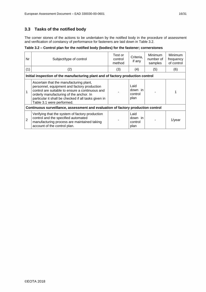
3.3 Tasks of the notified body
The corner stones of the actions to be undertaken by the notified body in the procedure of assessment and verification of constancy of performance for fasteners are laid down in Table 3.2.
Table 3.2 – Control plan for the notified body (bodies) for the fastener; cornerstones
Nr Subject/type of control Test or control method
Criteria, if any
Minimum number of samples
Minimum frequency of control
(1) (2) (3) (4) (5) (6)
Initial inspection of the manufacturing plant and of factory production control
1
Ascertain that the manufacturing plant, personnel, equipment and factory production control are suitable to ensure a continuous and orderly manufacturing of the anchor. In particular it shall be checked if all tasks given in Table 3.1 were performed.
-
Laid down in control plan
- 1
Continuous surveillance, assessment and evaluation of factory production control
2
Verifying that the system of factory production control and the specified automated manufacturing process are maintained taking account of the control plan.
-
Laid down in control plan
- 1/year

European Assessment Document – EAD 330030-00-0601 17/31
©EOTA 2018
4 REFERENCE DOCUMENTS
As far as no edition date is given in the list of standards thereafter, the standard in its current version at the time of issuing the European Technical Assessment is of relevance.
[1] EN 1469:2015 Natural stone products - Slabs for cladding - Requirements
[2] EN 14411:2016 Ceramic tiles - Definition, classification, characteristics, assessment and verification of constancy of performance and marking
[3] EN 438-7:2005 High-pressure decorative laminates (HPL) - Sheets based on thermosetting resins (usually called laminates) - Part 7: Compact laminate and HPL composite panels for internal and external wall and ceiling finishes
[4] EN 12467:2012+A1:2016 Fibre-cement flat sheets - Product specification and test methods
[5] EOTA TR 062:2018-07 EOTA Technical Report: Design of fasteners for façade panels made of natural stone (except slate)
[6] EN 1993-1-4:2006+ A1:2015
Eurocode 3: Design of steel structures - Part 1-4: General rules - Supplementary rules for stainless steels
[7] EN ISO 3506-1 Mechanical properties of corrosion-resistant stainless steel fasteners - Part 1: Bolts, screws and studs
[8] EN ISO 6506-1:2014 Metallic materials - Brinell hardness test - Part 1: Test method
[9] EN ISO 6507-1:2005 Metallic materials - Vickers hardness test - Part 1: Test method
[10] EN ISO 4892-2:2013 Plastics - Methods of exposure to laboratory light sources - Part 2: Xenon-arc lamps
[11] EN 12372:2006 Natural stone test methods - Determination of flexural strength under concentrated load
[12] EN 12440:2008 Natural stone – Denomination criteria

European Assessment Document – EAD 330030-00-0601 18/31
©EOTA 2018
ANNEX A TEST PROGRAM AND DETAILS OF TESTS
A.1 Test program
Table A.1 Test program
N° Purpose of test Tests only if Min. number
of tests Req.
A1a Tension tests (Reference) 10
A1b Tension tests with maximum spacing 3x5
A1c Tension test with minimum edge distance min ar < 100 mm 10
A1d Tension tests with support rotation hnom < 12mm, hs < 8 mm and
stand-off installation 2x5
A2a Shear tests 10
A2b Shear test with minimum edge distance min ar < 100 mm 10
A3 Tests with combined tension and shear loading
(6) 5
F1 Tension tests – sensitivity to tolerances (4) 5 ≥ 0,9
F2 Tension tests under repeated loads (4) 5 ≥ 0,9
F3 Tension tests under sustained loading (5) 5 ≥ 0,9
Tests only if the reduction factor cannot be taken from the panel material (without marble)
F4 Tension tests under freeze-thaw cycles (2) 5 ≥ 0,9
F5 Tension tests after immersion in water (2) 5 ≥ 0,9
F6a Tension tests at temperature 60°C (1) (3) 5 ≥ 0,9
F6b Tension tests at temperature 80°C (1) (3) 5 ≥ 0,8
Tests only for natural stone marble
F4 Tension tests under freeze-thaw cycles 5 ≥ 1,0
F5 Tension tests after immersion in water 5 ≥ 1,0
Tests only for PMMA
F7 Tension tests after UV aging (3) 4x5 ≥ 0,9
(1) Only for resin bonded or plastic bonded panels, e. g. HPL, PMMA
(not for mineral bonded panels: e. g. natural stone, cast stone, ceramic tiles)
(2) No tests are required for cast stone, ceramic tiles, HPL, PMMA if following reduction factors will be considered: For water absorption ≤ 0,5%: α2,Fi = 0,8
For water absorption > 0,5%: α2,Fi = 0,7
No tests are required for natural stone of Stone group I, II and III.
No tests are required for natural stone of Stone group IV, Limestone and Sandstone if the following reduction factors will be considered: Limestone: α2,F4/F5 = 0,9
Sandstone: α2,F4/F5 = 0,5
(3) No tests are required for cast stone, ceramic tiles, HPL, PMMA if an reduction factor of α2,Fi = 0,7 will be considered
(4) No tests are required for fasteners with following dimensions in natural stone:
Undercut diameter ≥ drill hole diameter (cylindrical hole) +1,5 mm
The fastener completely fills the undercut.
Embedment depth: min. hs = 10 mm
(5) Only for resin bonded or plastic bonded panels, e. g. HPL, PMMA. Tests may be omitted, if the intended use is only for fixing of panels in vertical position (given in the ETA).
(6) Tests may be omitted if only characteristic tension and shear resistance is given in the ETA.
European Assessment Document – EAD 330030-00-0601 19/31
©EOTA 2018
A.2 Details of tests
A.2.1 General
All tests are carried out on the final product; any deviations have to be justified accordingly.
The tests are carried out on test specimens representative of the relevant panel material. If no other conditions are specified in the following sections, the size of the panel is 200 mm x 200 mm at minimum.
Drilling procedure and fastener installation are in accordance with the manufacturer's installation instructions. If no other conditions are specified in the following sections, the drillbit diameter is dcut,m and the drill hole diameter is d0,m.
If no other conditions are specified in the following sections the edge distance to both edges is 100 mm.
If no other conditions are specified in the following sections, the tests shall be performed under normal
environment conditions (ambient temperature = +21 5 °C on panel sections with single fasteners. Larger panels with several fasteners are possible as well, if spacing requirements are kept.
If no other conditions are specified the diameter of the supporting ring shall be chosen from the test series A1a according to where the failure mode changed from pull-out of the fixing element to bending failure of the test specimen.
The tests shall be carried out on the envisaged panel material to be fixed. The material used for the tests shall be specified in detail. The characteristic flexural strength values, the E-modulus and the durability of the material to be expected under the envisaged service conditions shall be indicated.
For testing the E-Modulus the displacement transducer shall be fixed directly on the panel.
If a technical specification of the panel material is not available, the characteristic strength values and the durability of the material have to be determined by testing.
Material used for bending tests, for tension/shear tests and for tests to determine the reduction factors shall come from the same batch.
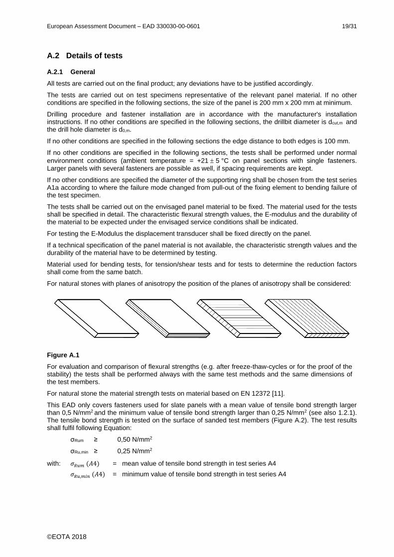
For natural stones with planes of anisotropy the position of the planes of anisotropy shall be considered:
Figure A.1
For evaluation and comparison of flexural strengths (e.g. after freeze-thaw-cycles or for the proof of the stability) the tests shall be performed always with the same test methods and the same dimensions of the test members.
For natural stone the material strength tests on material based on EN 12372 [11].
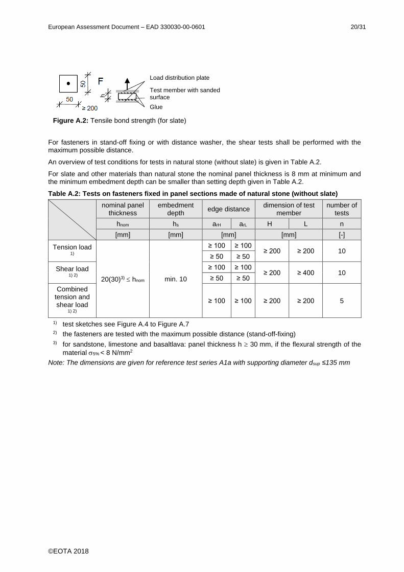
This EAD only covers fasteners used for slate panels with a mean value of tensile bond strength larger than 0,5 N/mm2 and the minimum value of tensile bond strength larger than 0,25 N/mm2 (see also 1.2.1). The tensile bond strength is tested on the surface of sanded test members (Figure A.2). The test results shall fulfil following Equation:
σRum ≥ 0,50 N/mm2
σRu,min ≥ 0,25 N/mm2
with: 𝜎𝑅𝑢𝑚 (𝐴4) = mean value of tensile bond strength in test series A4
𝜎𝑅𝑢,𝑚𝑖𝑛 (𝐴4) = minimum value of tensile bond strength in test series A4
European Assessment Document – EAD 330030-00-0601 20/31
©EOTA 2018
Figure A.2: Tensile bond strength (for slate)
For fasteners in stand-off fixing or with distance washer, the shear tests shall be performed with the maximum possible distance.
An overview of test conditions for tests in natural stone (without slate) is given in Table A.2.
For slate and other materials than natural stone the nominal panel thickness is 8 mm at minimum and the minimum embedment depth can be smaller than setting depth given in Table A.2.
Table A.2: Tests on fasteners fixed in panel sections made of natural stone (without slate)
nominal panel thickness
embedment depth
edge distance dimension of test
member number of
tests
hnom hs arH arL H L n
[mm] [mm] [mm] [mm] [-]
Tension load 1)
20(30)3) hnom min. 10
≥ 100 ≥ 100 ≥ 200 ≥ 200 10
≥ 50 ≥ 50
Shear load 1) 2)
≥ 100 ≥ 100 ≥ 200 ≥ 400 10
≥ 50 ≥ 50
Combined tension and shear load
1) 2)
≥ 100 ≥ 100 ≥ 200 ≥ 200 5
1) test sketches see Figure A.4 to Figure A.7 2) the fasteners are tested with the maximum possible distance (stand-off-fixing) 3) for sandstone, limestone and basaltlava: panel thickness h 30 mm, if the flexural strength of the
material 5% < 8 N/mm2
Note: The dimensions are given for reference test series A1a with supporting diameter dsup ≤135 mm
Load distribution plate
Test member with sanded surface
Glue
European Assessment Document – EAD 330030-00-0601 21/31
©EOTA 2018
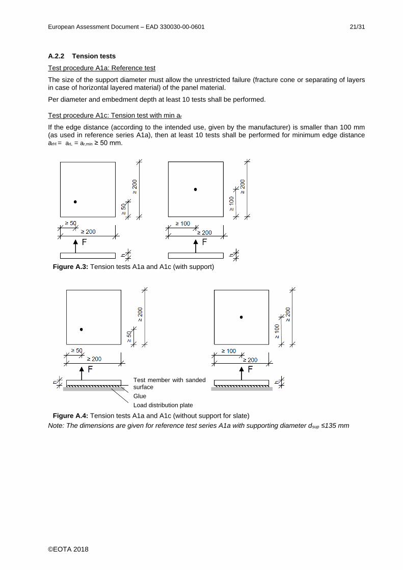
A.2.2 Tension tests
Test procedure A1a: Reference test
The size of the support diameter must allow the unrestricted failure (fracture cone or separating of layers in case of horizontal layered material) of the panel material.
Per diameter and embedment depth at least 10 tests shall be performed.
Test procedure A1c: Tension test with min ar
If the edge distance (according to the intended use, given by the manufacturer) is smaller than 100 mm (as used in reference series A1a), then at least 10 tests shall be performed for minimum edge distance arH = arL = ar,min ≥ 50 mm.
Figure A.3: Tension tests A1a and A1c (with support)
Figure A.4: Tension tests A1a and A1c (without support for slate)
Note: The dimensions are given for reference test series A1a with supporting diameter dsup ≤135 mm
Test member with sanded surface
Glue
Load distribution plate
European Assessment Document – EAD 330030-00-0601 22/31
©EOTA 2018
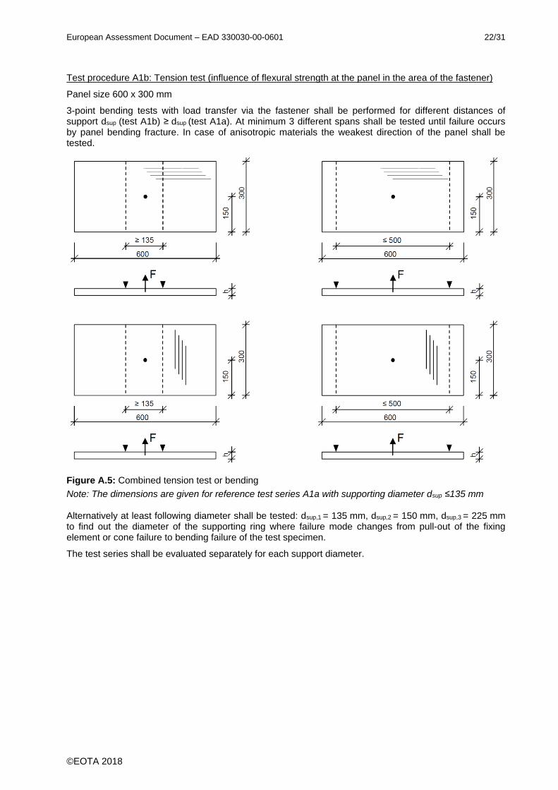
Test procedure A1b: Tension test (influence of flexural strength at the panel in the area of the fastener)
Panel size 600 x 300 mm
3-point bending tests with load transfer via the fastener shall be performed for different distances of support dsup (test A1b) ≥ dsup (test A1a). At minimum 3 different spans shall be tested until failure occurs by panel bending fracture. In case of anisotropic materials the weakest direction of the panel shall be tested.
Figure A.5: Combined tension test or bending
Note: The dimensions are given for reference test series A1a with supporting diameter dsup ≤135 mm
Alternatively at least following diameter shall be tested: dsup,1 = 135 mm, dsup,2 = 150 mm, dsup,3 = 225 mm to find out the diameter of the supporting ring where failure mode changes from pull-out of the fixing element or cone failure to bending failure of the test specimen.
The test series shall be evaluated separately for each support diameter.

European Assessment Document – EAD 330030-00-0601 23/31
©EOTA 2018
Test procedure A1d: Tension test with support rotation
For panels with a nominal panel thickness h = hnom ≤ 12 mm, hs < 8 mm and a stand-off installation of the fastener the support rotation is tested according to Figure A.6.
Tests are performed at the angle and at the angle 2
The angle corresponds to the angle when the clamp does not touch the panel.
Figure A.6: Combined tension test or shear test for an edge distance 100 / 100 mm
Note: The dimensions are given for reference test series A1a with supporting diameter dsup ≤135 mm
European Assessment Document – EAD 330030-00-0601 24/31
©EOTA 2018
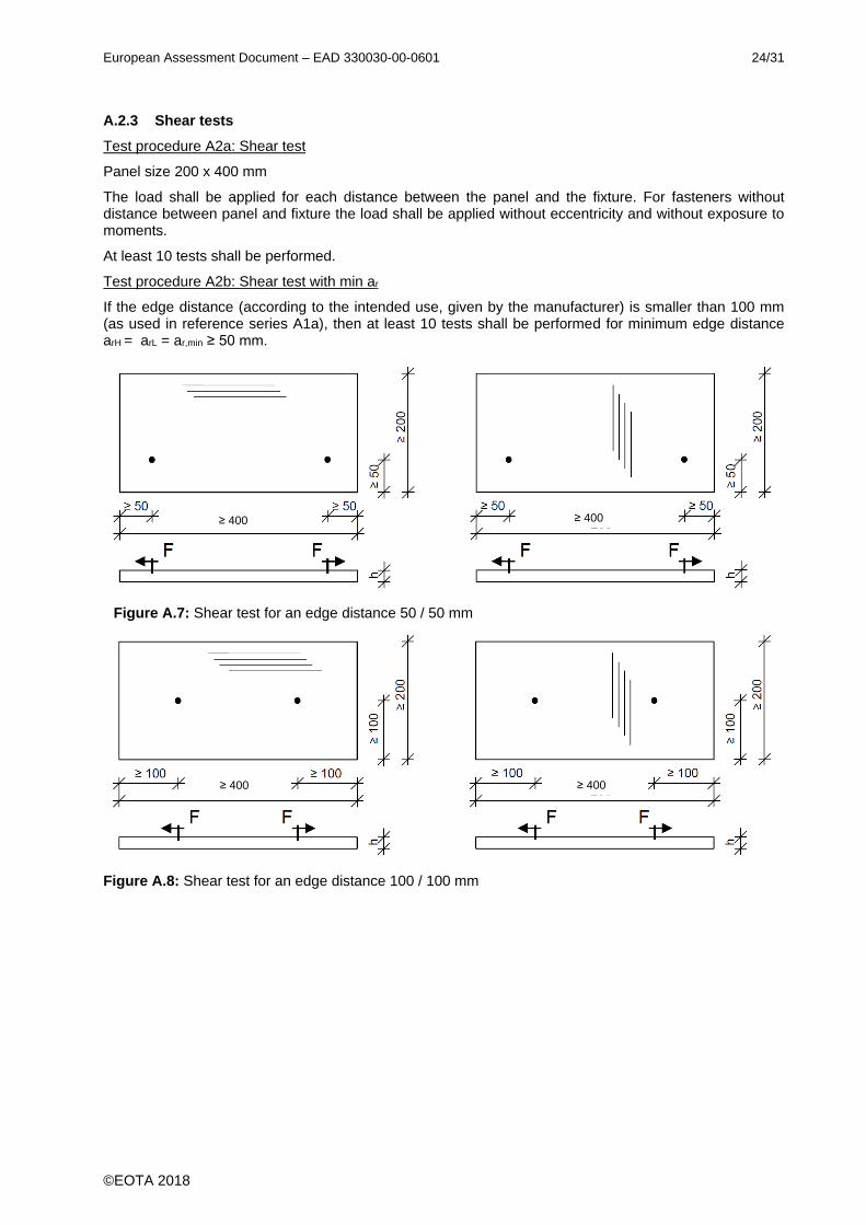
A.2.3 Shear tests
Test procedure A2a: Shear test
Panel size 200 x 400 mm
The load shall be applied for each distance between the panel and the fixture. For fasteners without distance between panel and fixture the load shall be applied without eccentricity and without exposure to moments.
At least 10 tests shall be performed.
Test procedure A2b: Shear test with min ar
If the edge distance (according to the intended use, given by the manufacturer) is smaller than 100 mm (as used in reference series A1a), then at least 10 tests shall be performed for minimum edge distance arH = arL = ar,min ≥ 50 mm.
Figure A.7: Shear test for an edge distance 50 / 50 mm
Figure A.8: Shear test for an edge distance 100 / 100 mm
≥ 400 ≥ 400
≥ 400 ≥ 400
European Assessment Document – EAD 330030-00-0601 25/31
©EOTA 2018
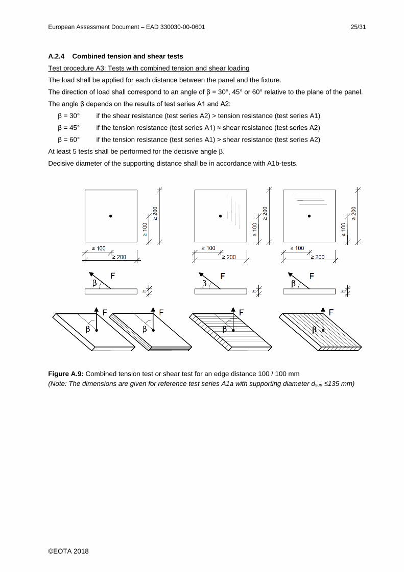
A.2.4 Combined tension and shear tests
Test procedure A3: Tests with combined tension and shear loading
The load shall be applied for each distance between the panel and the fixture.
The direction of load shall correspond to an angle of β = 30°, 45° or 60° relative to the plane of the panel.
The angle β depends on the results of test series A1 and A2:
β = 30° if the shear resistance (test series A2) > tension resistance (test series A1)
β = 45° if the tension resistance (test series A1) ≈ shear resistance (test series A2)
β = 60° if the tension resistance (test series A1) > shear resistance (test series A2)
At least 5 tests shall be performed for the decisive angle β.
Decisive diameter of the supporting distance shall be in accordance with A1b-tests.
Figure A.9: Combined tension test or shear test for an edge distance 100 / 100 mm
(Note: The dimensions are given for reference test series A1a with supporting diameter dsup ≤135 mm)

European Assessment Document – EAD 330030-00-0601 26/31
©EOTA 2018
A.2.5 Functioning tests
Test procedure F1: Sensitivity to fastener and drill bit tolerances
Axial tension tests shall be performed with fasteners with minimum fastener dimensions within the tolerances given by the manufacturer.
For drilling the drill bit diameter is dcut,max and the drill hole diameter is d0,max.
Test procedure F2: Functioning under repeated loads
The fastener shall be exposed to at least 10.000 load cycles at a frequency of about 2 Hz to 6 Hz. The upper load max N and the lower load min N shall be chosen as follows:
Nmax = 0,5 Nln5% (A1a)
Nmin = 0,2 Nln5% (A1a)
with Nln5% (according to B.3) of test series A1a
During each cycle the load shall vary like a sine curve between Nmax and Nmin. The displacement shall be measured during the first loading up to Nmax and either continuously or at least after 1, 10, 100, 1000, 10000 and 100000 load cycles.
After completion of the load cycles the fastener shall be unloaded, the displacement is measured and a tension test is performed.
Test procedure F3: Functioning under sustained loading
The long term behaviour of the fixing as well as of the material used shall be verified in relation to the assumed working life. Fasteners shall be capable of sustaining their design loads for the assumed working life of the fixture without significant increase in displacement which could render the anchorage ineffective. The initial value of load resistance shall be maintained or the reduction of load resistance shall be taken into account accordingly.
The fastener shall be loaded with a sustained load of:
Nsus = 0,4 Nln5% (A1a)
with Nln5% (according to B.3) of test series A1a
The value of the constant load corresponds to the envisaged service conditions (e.g. dead load of the facade panel).
The displacement shall be measured during the first loading up and then continuously.
Maintain the load and measure the displacements until the displacements appear to have stabilised, but at least for three months.
After completion of the sustained loading the fastener shall be unloaded, the displacement is measured and a tension test is performed.
Test procedure F4: Functioning after freeze-thaw cycles
The fastener shall be exposed to 25 freeze-thaw cycles according to the product standard of the relevant material.
If no test procedures according to standards are available for the material, the following procedure shall be performed:
- 24 hours water storage - Cooling (freezing) in air to -20±4°C within 1-2 hours, keeping this temperature for another hour
- Warm up (thaw) in a water bath to +20±4°C within 1-2 hours, keeping this temperature for another
hour
After completion of freeze-thaw cycles a tension test shall performed.
European Assessment Document – EAD 330030-00-0601 27/31
©EOTA 2018
Test procedure F5: Functioning after immersion in water
The test specimens shall be storage in water for 24 hours. Then axial tension tests are carried out.
Test procedure F6 : Functioning after temperature
These tests are performed to determine the performance of the fastener under increased temperature simulating service conditions that vary within the considered temperature range.
The tests shall be carried out at maximum long term temperature (tests F6a: 60°C) and maximum short term temperature (tests F6b: 80°C).
Raise test member temperature to required test temperature at a rate of approximately 20 K per hour. Keep the test member at this temperature for 24 hours.
Then axial tension tests are carried out.
Test procedure F7: Functioning after UV aging
The tests shall be performed according to EN ISO 4892-2 [10], Method A, Cycle 1. After 1500, 2000,
2500 and 3000 hours at least 5 tests each shall be carried out.
European Assessment Document – EAD 330030-00-0601 28/31
©EOTA 2018
A.3 Test report
Since only relevant parameter shall be followed for each test series this table is meant as a check list. The test report shall include the appropriate information for the particular test series.
1. Description test specimen
Fastener type Manufacturer, trade name
Fastener dimensions e.g. fastener diameter ds [mm],
fastener length Ls [mm]
Status of specimen, production lot / batch serial product / prototype
Mechanical properties of the fastener (tensile strength, yield limit, fracture elongation), type of coating,
e.g. fu,test = 970 N/mm², fy,test = 890 N/mm²
2. Test member
Panel material e. g. natural stone, HPL
Panel dimensions Length L and height H [mm]
Panel nominal thickness h
Panel specification Flexural strength u5%,test
3. Setting/ Installation information
diameter of support e. g. dsup = 135 mm
Drilling method, type of drilling machine
Type and cutting diameter of drill bit
For stop drills: length of drill bit
Diameter of drill hole d0 [mm]
Diameter of undercut d1 [mm]
Borehole depth h1 [mm]
Embedment depth of the fastener hs [mm]
Thickness of clamp material tfix [mm]
Clearance hole df [mm]
Installation torque TInst [Nm]
4. Test parameter
Diameter of support e. g. D = 135 mm
Applied repeated load
Applied min. / max. sustained load
Measuring of fastener displacement e.g. continuously / at the fastener
Min. / max frequency during the test
5. Test results
Load at failure
Load at loss of adhesion
Displacement at failure
Displacement at 50% of failure load
Diagram with load displacement curve
Failure mode e.g. steel failure or pull-out failure or breakout
Diagram with displacement over time of testing (long term tests only)
European Assessment Document – EAD 330030-00-0601 29/31
©EOTA 2018
ANNEX B GENERAL ASSESSMENT METHODS
B.1 Conversion of failure loads to nominal strength
In some cases it can be necessary to convert the results of a test series to correlate with a façade panel strength different from that of the test member. When doing so, the type of failure shall be taken into account.
Conversion of test results for the influence of the façade panel flexural strength in accordance with following Equation:
𝑓σ = σ5%
σu5%,test ≤ 1,0 (B.1)
with: f = conversion factor if the flexural strength of the panel used for tests is higher than the value given in the intended use of the ETA for the fastener
σu5%,test = lower expectation value of flexural strength of the tested panel according to B.3
σ5% = flexural strength given in ETA as intended use for the fastener (if the panel is specified
according to a hEN this value corresponds to the flexural strength given in the Declaration of performance of the panel)
In the case of steel failure the failure load shall be converted to the nominal steel strength by following Equation:
FRu fuk = FtRu · fuk / fu,test (B.2)
with: FRu (fuk) = failure load at nominal steel ultimate strength fuk
FtRu = failure load at a test
fuk = nominal steel ultimate strength
fu,test = steel ultimate strength at a test
B.2 Criteria regarding scatter of failure loads (reduction factor v)
In each test series according to Table A.1, the coefficient of variation of the ultimate load shall be
calculated and the reduction factor v for each test series shall be calculated according to following Equation:
v = 1 / (1 + 0,03 • (vu [%] - 20)) ≤ 1,0 (B.3)
with: vu = coefficient of variation of ultimate load of tests according Table A.1, ratio between the standard deviation value and the mean value
B.3 Establishing 5 % fractile
The 5%-fractile of the ultimate loads measured in a test series is to be calculated according to statistical procedures for a confidence level of 75 % using logarithmical normal distribution of the single test results and unknown standard deviation of the population.
Fln5% = FRu,m ln(x) - ks • s ln(x) (B.4)
with: Fln5% = 5%-logarithmic fractile of the ultimate load calculated by the logarithmic test values
FRu,m ln(x) = mean-value of ultimate load in a test series calculated by the logarithmic test values
ks = statistical factor
e.g.: n = 5 tests: ks = 2,47
n = 10 tests: ks = 2,11
n = 20 tests: ks = 1,94
s ln(x) = standard deviation calculated by the logarithmic test values
European Assessment Document – EAD 330030-00-0601 30/31
©EOTA 2018
B.4 Determination of reduction factors (reduction factors 2)
For all test series F1 to F7 the factor shall be calculated according to following Equation:
= 𝑁𝑅𝑢𝑚 (𝐹𝑖)
𝑁𝑅𝑢𝑚 (𝐴1𝑎) ≤ 1,0 (B.5)
with: 𝑁𝑅𝑢𝑚 (𝐹𝑖) = mean value of ultimate loads in test series F1 to F7 according to Table A1
𝑁𝑅𝑢𝑚 (𝐴1𝑎) = mean value of ultimate loads in the reference test A1a according to Table A1
The factor α2,Fi shall be calculated for each test series Fi.
2,Fi = 𝛼
𝑟𝑒𝑞 𝛼 ≤ 1,0 (B.6)
with: = value according to Equation (B.5) in the test series
req. = required value of according to Table A.1
For test series F4 to F7 the factor 2,Fi may be taken from the panel material.
If no tests F4 or F5 are performed for cast stone, ceramic tiles, HPL, PMMA:
For water absorption ≤ 0,5%: α2,Fi = 0,8
For water absorption > 0,5%: α2,Fi = 0,7
If no tests F4 or F5 are performed for natural stone:
Limestone: α2,F4/F5 = 0,9
Sandstone: α2,F4/F5 = 0,5
Stone group I, II and III: α2,F4/F5 = 1,0
If no tests F6 are performed in resin bonded or plastic bonded panels (e.g. HPL, PMMA): 2,F6= 0,7
For mineral bonded panels (e.g. natural stone, cast stone, ceramic tiles):2,F6= 1,0
If no tests F7 are performed in PMMA: 2,F7= 0,7
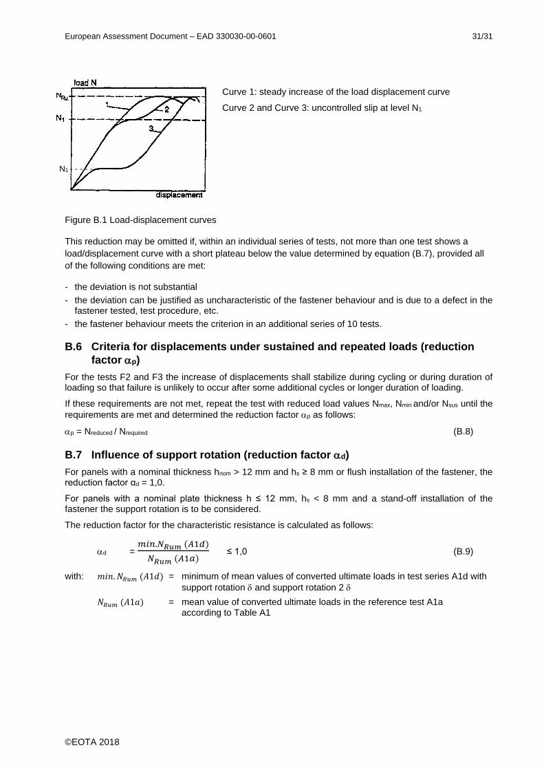
B.5 Criteria for uncontrolled slip under tension loading (reduction factor 1)
Uncontrolled slip is characterised by a significant change of stiffness, see Figure B.1. The corresponding load when uncontrolled slip starts is called N1. The value N1 shall be evaluated for every tension test from the measured load displacement curve. If the load/displacement curves show a steady increase then N1 = NRu (see Figure B.1, curve 1).
For tension tests the factor 1 shall be calculated for each test series according to equation:
α1 = 𝛼𝑁
𝑟𝑒𝑞 𝛼 ≤1,0 (B.7)
with αN = lowest ratio N1/NRu in the test series
N1 = load at which uncontrolled slip of the fastener occurs (see Figure B.1)
Nu = failure load in the test
req α = 0,8
European Assessment Document – EAD 330030-00-0601 31/31
©EOTA 2018
Curve 1: steady increase of the load displacement curve
Curve 2 and Curve 3: uncontrolled slip at level N1
Figure B.1 Load-displacement curves
This reduction may be omitted if, within an individual series of tests, not more than one test shows a
load/displacement curve with a short plateau below the value determined by equation (B.7), provided all
of the following conditions are met:
- the deviation is not substantial
- the deviation can be justified as uncharacteristic of the fastener behaviour and is due to a defect in the fastener tested, test procedure, etc.
- the fastener behaviour meets the criterion in an additional series of 10 tests.
B.6 Criteria for displacements under sustained and repeated loads (reduction
factor p)
For the tests F2 and F3 the increase of displacements shall stabilize during cycling or during duration of loading so that failure is unlikely to occur after some additional cycles or longer duration of loading.
If these requirements are not met, repeat the test with reduced load values Nmax, Nmin and/or Nsus until the
requirements are met and determined the reduction factor p as follows:
p = Nreduced / Nrequired (B.8)
B.7 Influence of support rotation (reduction factor d)
For panels with a nominal thickness hnom > 12 mm and hs ≥ 8 mm or flush installation of the fastener, the reduction factor αd = 1,0.
For panels with a nominal plate thickness h ≤ 12 mm, hs < 8 mm and a stand-off installation of the fastener the support rotation is to be considered.
The reduction factor for the characteristic resistance is calculated as follows:
d = 𝑚𝑖𝑛.𝑁𝑅𝑢𝑚 (𝐴1𝑑)
𝑁𝑅𝑢𝑚 (𝐴1𝑎) ≤ 1,0 (B.9)
with: 𝑚𝑖𝑛. 𝑁𝑅𝑢𝑚 (𝐴1𝑑) = minimum of mean values of converted ultimate loads in test series A1d with
support rotation and support rotation 2
𝑁𝑅𝑢𝑚 (𝐴1𝑎) = mean value of converted ultimate loads in the reference test A1a according to Table A1
N1 - - - - - -


![1 Taiwan International Fastener Show [Profile] Taiwan External Trade Develop Council (TAITRA) Taiwan Industrial Fasteners Institute.](https://static.fdocuments.us/doc/165x107/56649d185503460f949eda3e/1-taiwan-international-fastener-show-profile-wwwfastenertaiwancom-taiwan.jpg)
