Fast Frequency Support Control in the GB Power … · have been built and implemented both in PSCAD...
6
978-1-5386-1953-7/17/$31.00 ©2017 IEEE Fast Frequency Support Control in the GB Power System using VSC-HVDC Technology Luis Orellana, Víctor Matilla, Sheng Wang, Oluwole D. Adeuyi, and Carlos E. Ugalde-Loo School of Engineering, Cardiff University Cardiff, Wales, UK Abstract—A fast frequency support control scheme for voltage source converter based high-voltage direct-current (HVDC) links has been designed, simulated and experimentally implemented and validated. The effectiveness of the proposed scheme has been tested on simplified GB power system models with both averaged and switched converter models. System performance has been initially assessed using different software simulation platforms (PSCAD and MATLAB/Simulink). System validation has been carried out using an experimental test-rig. It is shown that simulation and experimental results agree on well when the fast frequency support provision is enabled. For completeness, the effectiveness of the control scheme has been tested for two contingency scenarios: (i) when a high-voltage alternating-current interlink in parallel with the HVDC link is disconnected, and (ii) for a substantial increase in system load. Keywords—fast frequency support; VSC-HVDC systems, modelling, simulation, experimental validation. I. INTRODUCTION The levels of inertia present on the Great Britain (GB) power system have been declining due to the replacement of conventional synchronous generation with low-carbon technologies [1], [2]. Since these technologies are generally integrated to the system through power converters, they do not inherently contribute to the system inertia unless they are fitted with supplementary controllers [2]-[4]. The benefits that high- voltage direct-current (HVDC) technologies based on voltage source converters (VSCs) have over line commutated converters have positioned the VSC as a feasible topology to mitigate inertia issues [5]. Averaged and switched models are usually employed to represent the behaviour of VSCs. The averaged model is a simple configuration based on controllable voltage and current sources; however, it requires additional elements for its start-up (e.g., series resistance to limit the current). On the other hand, the switched model simulates the real switching process of semiconductor devices within the VSC and requires additional components to minimise harmonics [6]. In this paper, the performance of a fast frequency support control scheme is studied. This supplementary control loop has been fitted in averaged and switched VSC models. The scheme limits the rate of change of frequency and contains frequency deviations by suitably modifying the DC voltage and active power references of the converters. Power system models emulating the frequency response of the GB power system have been built and implemented both in PSCAD and MATLAB/Simulink. To evaluate the capabilities of the fast frequency support scheme, simulations have been carried out for an infrequent power infeed loss in the GB grid. Simulation results show that the frequency response of the system improves if the proposed support controller is activated. A good performance is obtained irrespectively of the converter model employed. To validate the performance of the proposed scheme, an experimental VSC- HVDC test-rig has been used. It is shown that both experimental and simulation results exhibit a good agreement. For completeness, further simulation case studies representing potential contingency operating scenarios in the future GB power system have been assessed to demonstrate the effectiveness of the fast frequency support scheme. II. VSC-HVDC TRANSMISSION SYSTEMS The system under study consists of an HVDC power transmission link connecting an AC system with a model representing the GB power system. The HVDC link employs VSC technology. This section describes the test system and the VSC-HVDC control architecture. 100 km DC XLPE Cable 1 000 MW ± 320 kV GB SYSTEM MODEL ~ Sending-end Converter Unit Receiving-end Converter Unit 400 kV 50 Hz 400 kV 50 Hz 400/320 kV Y/Δ 320/400 kV Δ/Y Figure 1. System under study: VSC-HVDC link connecting two AC systems. This work was supported in part by the EU FP7 Programme through the project “Beyond State of the art Technologies for re-Powering AC corridors & multi-Terminal HVDC Systems” (BEST PATHS), grant agreement number 612748.
Transcript of Fast Frequency Support Control in the GB Power … · have been built and implemented both in PSCAD...

978-1-5386-1953-7/17/$31.00 ©2017 IEEE
Fast Frequency Support Control in the GB Power System using VSC-HVDC Technology
Luis Orellana, Víctor Matilla, Sheng Wang, Oluwole D. Adeuyi, and Carlos E. Ugalde-Loo School of Engineering, Cardiff University
Cardiff, Wales, UK
Abstract—A fast frequency support control scheme for voltage source converter based high-voltage direct-current (HVDC) links has been designed, simulated and experimentally implemented and validated. The effectiveness of the proposed scheme has been tested on simplified GB power system models with both averaged and switched converter models. System performance has been initially assessed using different software simulation platforms (PSCAD and MATLAB/Simulink). System validation has been carried out using an experimental test-rig. It is shown that simulation and experimental results agree on well when the fast frequency support provision is enabled. For completeness, the effectiveness of the control scheme has been tested for two contingency scenarios: (i) when a high-voltage alternating-current interlink in parallel with the HVDC link is disconnected, and (ii) for a substantial increase in system load.
Keywords—fast frequency support; VSC-HVDC systems, modelling, simulation, experimental validation.
I. INTRODUCTION
The levels of inertia present on the Great Britain (GB) power system have been declining due to the replacement of conventional synchronous generation with low-carbon technologies [1], [2]. Since these technologies are generally integrated to the system through power converters, they do not inherently contribute to the system inertia unless they are fitted with supplementary controllers [2]-[4]. The benefits that high-voltage direct-current (HVDC) technologies based on voltage source converters (VSCs) have over line commutated converters have positioned the VSC as a feasible topology to mitigate inertia issues [5].
Averaged and switched models are usually employed to represent the behaviour of VSCs. The averaged model is a simple configuration based on controllable voltage and current sources; however, it requires additional elements for its start-up
(e.g., series resistance to limit the current). On the other hand, the switched model simulates the real switching process of semiconductor devices within the VSC and requires additional components to minimise harmonics [6].
In this paper, the performance of a fast frequency support control scheme is studied. This supplementary control loop has been fitted in averaged and switched VSC models. The scheme limits the rate of change of frequency and contains frequency deviations by suitably modifying the DC voltage and active power references of the converters. Power system models emulating the frequency response of the GB power system have been built and implemented both in PSCAD and MATLAB/Simulink.
To evaluate the capabilities of the fast frequency support scheme, simulations have been carried out for an infrequent power infeed loss in the GB grid. Simulation results show that the frequency response of the system improves if the proposed support controller is activated. A good performance is obtained irrespectively of the converter model employed. To validate the performance of the proposed scheme, an experimental VSC-HVDC test-rig has been used. It is shown that both experimental and simulation results exhibit a good agreement. For completeness, further simulation case studies representing potential contingency operating scenarios in the future GB power system have been assessed to demonstrate the effectiveness of the fast frequency support scheme.
II. VSC-HVDC TRANSMISSION SYSTEMS
The system under study consists of an HVDC power transmission link connecting an AC system with a model representing the GB power system. The HVDC link employs VSC technology. This section describes the test system and the VSC-HVDC control architecture.
100 km DC XLPE Cable
1 000 MW
± 320 kV
GBSYSTEMMODEL
~
Sending-endConverter
Unit
Receiving-endConverter
Unit
400 kV50 Hz
400 kV50 Hz
400/320 kVY/Δ
320/400 kVΔ/Y
Figure 1. System under study: VSC-HVDC link connecting two AC systems.
This work was supported in part by the EU FP7 Programme through the project “Beyond State of the art Technologies for re-Powering AC corridors & multi-Terminal HVDC Systems” (BEST PATHS), grant agreement number 612748.
A. Test System
A diagram of the test system is shown in Fig. 1. The rated power of the converters and cables of the HVDC link is 1000 MW and an operating DC voltage of ±320 kV is employed. The VSCs are connected on the AC sides via delta-star transformers which step-up the AC side voltage from 320 kV to 400 kV. A three-phase AC voltage source (400 kV, 50 Hz) is used to simulate the AC system.
B. VSC-HVDC Control
The main purpose of the VSC controller is to generate a controllable fundamental frequency waveform to regulate the electrical power conversion (from AC to DC or vice versa). The vector control strategy is utilised in this paper. In this technique, reference frame transformations are employed to represent all system variables in a dq rotating reference frame [7]; consequently, AC variables give the impression to be DC quantities. This enables an independent control of variables of interest. The control goals are achieved using a two-level cascaded controller, where the outer control loop meets the system performance objectives (for active and reactive power, DC voltage, and AC voltage references) and the inner control loop ensures the protection and stability of the converters [8].
Fig. 2 shows a schematic diagram of the converter outer control loop, where measured variables from the system are converted to current references (idref and iqref) for the inner control loop. The d-axis current is used to regulate active power or DC voltage. Conversely, the q-axis current is employed to control reactive power or AC voltage [8]. In the inner control loop (see Fig. 3), current is regulated using PI control structures and feed-forward voltage terms [9]. The outputs of the controller are voltage references (vdref and vqref), which are modulated to produce control signals in the averaged model or gate firing pulses in the switched model.
C. GB Power System Models
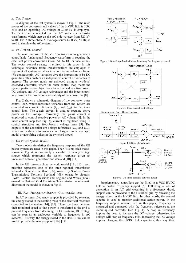
Two models simulating the frequency response of the GB power system are used in this paper. The GB simplified model, shown in Fig. 4, is essentially a variable frequency voltage source which represents the system response given an imbalance between generation and demand [10], [11].
In the GB three-machine network model [12], [13], each machine represents one of the three regional transmission networks: Southern Scotland (SS), owned by Scottish Power Transmission; Northern Scotland (NS), owned by Scottish Hydro Electric Transmission; and England and Wales (E/W), owned by National Grid Electricity Transmission. A schematic diagram of the model is shown in Fig. 5.
III. FAST FREQUENCY SUPPORT CONTROL SCHEME
In AC systems, frequency support is provided by releasing the energy stored in the rotating mass of the electrical machines connected to the system [14], [15]. These machines decrease their rotational speed so that power is transferred to the grid to prevent frequency from declining. In DC systems, DC voltage can be seen as an analogous variable to frequency in AC systems. This way, the energy stored in the HVDC link can be used to provide frequency support [16], [17].
Figure 2. Outer loop fitted with supplementary fast frequency control.
Figure 3. Inner current control loop.
Figure 4. GB simplified model.
Figure 5. GB three-machine network model.
Supplementary controllers can be fitted to a VSC-HVDC link to enable frequency support [5]. Following a loss of generation in an AC grid (resulting in a frequency drop), support can be provided to the disturbed grid by releasing the energy stored in the HVDC link. In other words, the control scheme is used to transfer additional active power. In the frequency support scheme used in this paper, frequency is measured and compared with the frequency reference at the receiving-end converter (see Fig. 1). A drop in frequency implies the need to increase the DC voltage; otherwise, the voltage will drop as frequency falls. Increasing the DC voltage implies charging the HVDC link capacitors; this way their

stored energy could be provided during a frequency drop event. The drop in voltage induced by the receiving-end converter implies the need to import active power to charge the HVDC link capacitor; therefore, the power reference in the sending-end converter should be increased.
The frequency support control scheme described previously has been implemented on the outer control loop, as shown in Fig. 2. Gain Kf in the receiving-end converter is defined as the ratio between the maximum permissible variation of DC voltage and the maximum drop expected in the system frequency. On the other hand, gain KVdc is defined as the ratio between the maximum additional active power that can be delivered (the difference between the rated power and the ongoing operational power) and the maximum permissible variation of DC voltage. As a result, providing additional power for frequency support will not risk the operational limits of the system.
IV. EXPERIMENTAL TEST-RIG
The experimental equipment used in this paper consists of a multi-terminal HVDC test-rig. This is shown in Fig. 6. It contains a cabinet with three VSC terminals, a DC network cabinet, autotransformers, and an isolation transformer. Further details on the test-rig operation can be found in [18]. For this paper, only two converters are employed. The controllers of the physical VSCs have been developed in Simulink and uploaded into a dSPACE tool, which in turn is used for data acquisition, monitoring and control. The controllers are based on the two-level cascaded control scheme described in Section II. The outer loop of the receiving-end VSC controls DC voltage and reactive power, and the outer loop at the sending-end VSC regulates active and reactive power.
ACDC
ACDC
ACDC
DC Network Cabinet
VSC Cabinet
dSPACEcontroller
ACAC
TR3
TR2
VSC 1
VSC 2
VSC 3
ControlDesk
Telecommunications signal400 VLL AC240 VLG AC140 VLL AC250 V DC
(a)
DC NetworkCabinet
Autotransformers(TR1 & 2)
IsolationTransformer(TR3)
Cables andshroudedconnectors
3-TerminalVSC Cabinet
Control Desk
(b)
Figure 6. VSC-HVDC experimental test-rig: (a) Schematic diagram. (b) Physical equipment.
The receiving-end converter (VSC1) is supplied from an autotransformer (TR2) and the sending-end converter (VSC2) is fed from the isolation transformer (TR3). The HVDC link is formed by connecting the VSCs with an equivalent DC link cable impedance in the DC Network Cabinet. The dSPACE controller is connected using communication cables between the VSCs and the Control Desk.
V. SIMULATION AND EXPERIMENTAL RESULTS
A VSC-HVDC link connecting the simplified GB power system model to another AC grid is used for simulation and experimental verification of the fast frequency control scheme. An infrequent power infeed loss (1800 MW) is simulated to assess the performance of the frequency support scheme presented in Section III. The GB simplified model has been used to emulate an inertia level for the Gone Green Scenario 2030/31 as this exhibits the lowest value among all scenarios proposed by National Grid [1].
Results are summarised in Fig. 7. These include simulation results obtained from MATLAB/Simulink when an averaged converter model is used, from PSCAD when both averaged and switched converter models are employed, and experimental results from the test-rig. As it can be observed, the DC voltage reduces and active power increases when the frequency drops following the power imbalance in the system (i.e., demand is greater than generation).
The active power provided by the HVDC link doubles from its initial operating point (0.4 to 0.8 p.u.) at the lowest frequency value. The initial value represents an average load condition and the change in power is within the capability of the converter, which is designed with some redundancy to deliver extra power. Although the DC voltage reduces by 8% in all cases, it is kept within permissible limits (i.e., within ±10% [19]). Frequency recovers and reaches steady-state 14 seconds after the disturbance occurred. Active power and DC voltage behave in a similar way due to the proportional relationship in the supplementary frequency support controller. However, the initial operating condition is not recovered as the disturbance in the system remains present and the rated power of the HVDC link is inferior to the magnitude of the power infeed loss event.
With regards to the simulation results, it should be highlighted that the system frequency remains within statutory limits for an infrequent power infeed loss when switched converter models are used, as shown in Fig. 7(c). However, frequency slightly falls below 49.5 Hz when the averaged model is employed, as shown in Figs. 7(a) and 7(b). This may be attributed to the power losses in the DC link. A 2.7% in power losses has been measured when the system reaches steady-state. These losses are higher than those when the switched model is used (see Fig. 7(c)).
As it can be observed in Fig. 7(d), the experimental results from the test-rig agree on well with those obtained through computer simulations. Although the frequency in the test-rig falls to a slightly lower value than in the PSCAD and MATLAB/Simulink simulation results, this is attributed to the higher power losses (around 5.6 %).

Freq
uenc
y [H
z]Po
wer
[p
u]D
C V
olta
ge
[pu]
Figure 7. System frequency, active power, and DC voltage. Results using: (a) converter averaged models (MATLAB); (b) converter averaged models (PSCAD); (c) converter switched models (PSCAD); (d) experimental HVDC test-rig. Blue traces represent variables measured at the terminals of the sending-end converter.
Green traces represent receiving-end converter measurements.
Figure 8. VSC-HVDC link embedded within the GB three-machine network.
VI. VSC-HVDC LINK EMBEDDED WITHIN THE GB THREE-MACHINE NETWORK
Fig. 8 shows the GB three-machine network model [12] with an embedded VSC-HVDC link connected between Buses 1 and 4. The following two power system contingencies are simulated using PSCAD to demonstrate the effectiveness of the fast frequency control scheme: (i) disconnection of the parallel high-voltage alternating-current (HVAC) interlink; and (ii) 1320 MW load increase.
A. Disconnection of Parallel HVAC Interlink
The loss of an HVAC interlink between interconnected AC systems results in a system split and creates an opposing frequency trend in the different areas. For the system shown in Fig. 8, this will reflect on a high frequency in SS and a low frequency in NS and E/W. Fig. 9 shows simulation results when the AC interlink between Buses 1 and 4 is disconnected. Such a system disturbance occurs at t = 2 s. A red trace has been used when no fast frequency support is employed and a blue trace when the support scheme is activated.
For the case without frequency support, Fig. 9(a) shows that the measured frequency in SS increases to 51.9 Hz due to
the sudden load loss and the frequency in E/W and NS drops to 49.8 Hz due to generation loss. However, if the proposed frequency support scheme is enabled (blue traces), the frequency deviation in SS reduces to 50.42 Hz and in E/W and NS to 49.95 Hz. In this case, active power quickly transferred through the VSC-HVDC link helped to contain the system frequency deviation on the interconnected areas.
The DC voltage variation is shown in Fig. 9(b). As it can be observed, this is within permissible limits of ±10% once the fast frequency support is active. Figs. 9(d) to 9(f) show the generator active power output in E/W, NS and SS, respectively. If fast frequency support is provided, the active power taken from the three synchronous generators reduces by about 200 MW compared to the case with no support.
Figs. 9(g) to 9(i) show the active power transferred through the HVAC links at E/W (Buses 3 and 4), NS (Buses 2 and 4) and SS (Buses 1 and 4). At t = 2 s, the active power flowing through the HVAC interlink between Buses 1 and 4 is reduced from 370 to 0 MW (see Fig. 9(i)) due to the disconnection of the AC line.

Figure 9. Simulation results due to disconnection of the parallel HVAC interlink with frequency support (blue) and without frequency support (red).
Figure 10. Simulation results due to 1320 MW sudden load increase with frequency support (blue) and without frequency support (red).
B. 1320 MW Load Increase
Embedded VSC-HVDC links connected in parallel with AC interlinks will not provide frequency support to the interconnected AC systems since the synchronous frequency is present at both terminals of the VSC link. To examine this scenario, simulations have been performed for a sudden 1320 MW load connection at t = 2 s. Fig. 10 shows the simulation results, with blue traces employed for the case of a fast frequency support upgraded system and red traces when no supplementary scheme is included.
As it can be observed in Fig. 10(a), the system frequency drops from 50 Hz to 49.3 Hz due to the sudden load increase regardless of the frequency support scheme being employed or not. Additionally, the DC voltage decreases from 640 kV to 580 kV when the frequency support scheme is active, thereby exceeding the permissible limit of ±10% (see Fig. 10(b)). Figs. 10(d)-10(f) show that about an additional 480 MW is taken
from the synchronous generators in E/W, NS and SS, due to the 1320 MW load increase. However, it should be highlighted that the fast frequency control provision results in an increased active power flow on the VSC-HVDC link (see Fig. 10(c)), thereby preventing overloading of the parallel AC interlink between Buses 1 and 4 (as seen in Fig. 10(i)).
VII. CONCLUSIONS
In this paper, the performance of a fast frequency support control scheme for VSC-HVDC systems has been designed, implemented and experimentally validated. The PSCAD and MATLAB/Simulink simulation engines have been employed to perform the computer simulations. Both averaged and switched VSC models have been implemented to test the effectiveness of the scheme. The results show that the averaged model closely reproduces the behaviour of its switched counterpart. In addition, the results obtained from both simulation platforms show a good agreement.

To validate the fast frequency support control scheme, an experimental VSC-HVDC test-rig has been used. Simulation and experimental results show a good agreement: In all cases, the frequency drop caused by a power imbalance was contained using the proposed control scheme. One of the advantages of the proposed scheme is that it auto-regulates itself: power injection rises as frequency falls and the system reaches steady-state at the same time as the frequency.
Additional simulation scenarios representing potential contingency operating conditions in the future GB power system have been assessed to demonstrate the effectiveness of the frequency support scheme. As it has been shown, fast frequency support from embedded VSC-HVDC links will help to contain high and low frequency deviations in inter-connected AC networks during system splits. Additionally, the scheme prevents overloading of existing AC lines during a large generation loss or a large sudden load increase.
Future work will be carried out to compare the presented fast frequency support control scheme with other control techniques available in the literature. Sensitivity studies addressing how changes in the control gains and on the permissible DC voltage variation affect the frequency support provision will be also conducted.
APPENDIX
A. Three-machine network [12]
Machine rating: 2800 MVA, 33 kV (SS); 2400 MVA, 33 kV (NS); 21000 MVA, 33 kV (E/W).
Synchronous generators (in p.u. in each generator base): Ra = 0.002, Xl = 0.17, Xq = 2.07, X'q = 0.906, X″q = 0.234, Xd = 2.13, X′d = 0.308, X″d = 0.234, Xmq = 1.9, Xmd = 1.96, t′d0 = 6.0857 s, t′q0 = 1.653 s, t″d0 = 0.0526 s, and t″q0 = 0.3538 s. Shaft inertia: HNS = 3.84 s, HSS = 3.84 s, and HEW = 5 s.
The following parameters are given in p.u. on a 1000 MVA base: Transformers: X11 = 0.14, X22 = X33 = 0.07. Transmission lines: X1 = 0.01, X2 = 0.1, X3 = 0.05, X/R ratio = 10. Loads: PL3 = 17.73, QL3 = 2.4847, PL4 = 2.0.
B. HVDC link control parameters
Outer control loop: Active Power: K = 0.005, T = 0.1 s; Reactive Power: K = 0.005, T = 0.1 s; DC voltage: K = 0.1, T = 0.1 s.
Inner control loop: Kd = 100, Td = 0.1 s, Kq = 100, Tq = 0.1 s, Td = 10 s. Frequency support: KVDC = 9.4 and Kf = 98.5. Filters: F(s) = G/(1 + sT); G = 1 and T = 0.8 s.
REFERENCES [1] National Grid, “Future Energy Scenarios,” 2015. Available:
www2.nationalgrid.com/UK/Industry-information/Future-of-Energy/ FES/Documents-archive/.
[2] National Grid, “System Operability Framework,” 2015. Available: www2.nationalgrid.com/UK/Industry-information/Future-of-Energy/ System-Operability-Framework/.
[3] J. Ekanayake and N. Jenkins, “Comparison of the Response of Doubly Fed and Fixed-Speed Induction Generator Wind Turbines to Changes in
Network Frequency,” IEEE Transactions on Energy Conversion, vol. 19, no. 4, pp. 800-802, Dec. 2004.
[4] K. F Jose, O. D. Adeuyi, J. Liang, and C. E. Ugalde-Loo, “Inertial Contribution from Large Scale Variable-Speed Wind Turbines Connected to the GB Grid,” in: 13th IET International Conference on AC and DC Power Transmission (ACDC 2017), Manchester, UK, 14-16 February 2017, pp. 1-6.
[5] O. D. Adeuyi, M. Cheah-Mane, J. Liang, and N. Jenkins, “Fast Frequency Response from Offshore Multi-terminal VSC-HVDC Schemes,” IEEE Transactions on Power Delivery, in press.
[6] A. Yazdani and R. Iravani, Voltage-Sourced Converters in Power Systems: Modeling, Control, and Applications, John Wiley & Sons, Ltd., 2015.
[7] D. van Hertem, O. Gomis-Bellmunt, and J. Liang, HVDC Grids, John Wiley & Sons, Inc., 2016.
[8] D. Jovcic and K. Ahmed, High-Voltage Direct Current Transmission: Converters, Systems and DC Grids, John Wiley & Sons, Ltd., 2015.
[9] CIGRE Working Group B4.57, “604 – Guide for the Development of Models for HVDC Converters in a HVDC Grid”, 2014.
[10] Y. Mu, J. Wu, J. Ekanayake, N. Jenkins, and H. Jia, “Primary Frequency Response From Electric Vehicles in the Great Britain Power System,” IEEE Transactions on Smart Grid, vol. 4, no. 2, pp. 1142-1150, June 2013.
[11] M. Cheng, J. Wu, S. J. Galsworthy, C. E. Ugalde-Loo, N. Gargov, W. W. Hung, and N. Jenkins, “Power System Frequency Response From the Control of Bitumen Tanks,” IEEE Transactions on Power Systems, vol. 31, no. 3, pp. 1769-1778, May 2016.
[12] F. M. Hughes, O. Anaya-Lara, N. Jenkins, and G. Strbac, “A Power System Stabilizer for DFIG-Based Wind Generation,” IEEE Transactions on Power Systems, vol. 21, no. 2, pp. 763-772, May 2006.
[13] L. Livermore, C. E. Ugalde-Loo, Q. Mu, J. Liang, J. B. Ekanayake, and N. Jenkins, “Damping of subsynchronous resonance using a voltage source converter-based high-voltage direct-current link in a series-compensated Great Britain transmission network,” IET Generation, Transmission & Distribution, vol. 8, no. 3, pp. 542-551, March 2013.
[14] I. Martínez Sanz, B. Chaudhuri, and G. Strbac, “Inertial Response From Offshore Wind Farms Connected Through DC Grids,” IEEE Transactions on Power Systems, vol. 30, no. 3, pp. 1518-1527, May 2015.
[15] A. Junyent-Ferre, Y. Pipelzadeh, and T. C. Green, “Blending HVDC-Link Energy Storage and Offshore Wind Turbine Inertia for Fast Frequency Response,” IEEE Transactions on Sustainable Energy, vol. 6, no. 3, pp. 1059-1066, July 2015.
[16] National Grid, “SMART Frequency Control Project – The Balance of Power,” 2015. Available: http://www.nationalgridconnecting.com/ The_balance_of_power/index.html
[17] J. Zhu, C. D. Booth, G. P. Adam, A. J. Roscoe, and C. G. Bright, “Inertia Emulation Control Strategy for VSC-HVDC Transmission Systems,” IEEE Transactions on Power Systems, vol. 28, no. 2, pp. 1277-1287, May 2013.
[18] J. Liang, T. Jing, O. Gomis-Bellmunt, J. Ekanayake, and N. Jenkins, “Operation and Control of Multiterminal HVDC Transmission for Offshore Wind Farms,” IEEE Transactions on Power Delivery, vol. 26, no. 4, pp. 2596-2604, Oct. 2011.
[19] O. D. Adeuyi, M. Cheah-Mane, J. Liang, N. Jenkins, Y. Wu, C. Li, and X. Gu, “Frequency support from modular multilevel converter based multiterminal HVDC schemes,” in Proc. Power & Energy Society General Meeting, Denver, USA, 26-30 July 2015, pp. 1–5.