Faranoff-Riley type I jet deceleration at density discontinuities
22
A&A 491, 321–337 (2008) DOI: 10.1051/0004-6361:20079185 c ESO 2008 Astronomy & Astrophysics Faranoff-Riley type I jet deceleration at density discontinuities Relativistic hydrodynamics with a realistic equation of state Z. Meliani 3 , R. Keppens 1,3,4 , and B. Giacomazzo 2 1 FOM-Institute for Plasma Physics Rijnhuizen, Nieuwegein 2 Max-Planck-Institut für Gravitationsphysik, Albert-Einstein-Institut, Golm, Germany 3 Centre for Plasma Astrophysics, KU Leuven (Leuven Mathematical Modeling and Computational Science Center), Belgium e-mail: [Zakaria.Meliani;Rony.Keppens]@wis.kuleuven.be 4 Astronomical Institute, Utrecht University, The Netherlands Received 4 December 2007 / Accepted 14 August 2008 ABSTRACT Aims. We propose a model that could explain the sudden jet deceleration in active galactic nuclei, thereby invoking density dis- continuities. Motivated particularly by recent indications from HYbrid MOrphology Radio Sources (HYMORS) that Fanaroff-Riley classification is induced in some cases by variations in the density of the external medium. We explore how one-sided jet deceleration and a transition to FR I type can occur in HYMORS, which start as FR II (and remain so on the other side). Methods. We implemented the Synge-type equation of state introduced in the general polytropic case by Meliani et al. (2004, A&A, 425, 773) into the relativistic hydrodynamic grid-adaptive AMRVAC code. To demonstrate its accuracy, we set up various test prob- lems in an appendix, which we compare to exact solutions that we calculate as well. We use the code to analyse the deceleration of jets in FR II/FR I radio galaxies, following them at high resolution across several hundred jet beam radii. Results. We present results for 10 model computations that vary the inlet Lorentz factor from 10 to 20, include uniform or decreasing density profiles, and allow for cylindrical versus conical jet models. As long as the jet propagates through uniform media, we find that the density contrast sets most of the propagation characteristics, fully consistent with previous modelling efforts. When the jet runs into a denser medium, we find a clear distinction in the decelaration of high-energy jets depending on the encountered density jump. For fairly high-density contrast, the jet becomes destabilised and compressed, decelerates strongly (up to subrelativistic speeds), and can form knots. If the density contrast is too weak, the high-energy jets continue with FR II characteristics. The trend is similar for the low-energy jet models, which start as underdense jets from the outset, and decelerate by entrainment into the lower region as well. We point out differences that are found between cylindrical and conical jet models, together with dynamical details like the Richtmyer-Meshkov instabilities developing at the original contact interface. Key words. hydrodynamics – galaxies: jets – ISM: jets and outflows – gamma rays: bursts 1. Introduction Accretion discs surrounding black holes, jets found in associ- ation with compact objects, and gamma ray bursts (GRBs) all represent violent astrophysical phenomena. They are associated with relativistic flows, both with respect to the occurring veloci- ties and to their prevailing equation of state. The jets from active galactic nuclei (AGN) and in GRBs are accelerated in a short dis- tance to reach a high Lorentz factor: typical values are γ ∼ 5−30 (Kellermann et al. 2004) for AGNs and γ> 100 for GRBs (Woods & Loeb 1995; Sari & Piran 1995). In this acceleration phase, situated at the base of the jet, it is believed that jet en- ergy is dominated by thermal energy and Poynting flux and that a fraction of these energies contributes to the efficient accelera- tion of the flow. Becaus of this, the relativistic fluid changes its state from relativistic, corresponding to an effective polytropic index Γ= 4/3, to classical (polytropic index Γ= 5/3) when the thermal energy is converted to kinetic energy. Farther along the jet paths, where the jets interact with the surrounding medium, a fraction of the directed kinetic energy is also converted into thermal energy as the shock fronts formed. According to the Appendices are only available in electronic form at http://www.aanda.org prevailing Lorentz factor of the jet, these shocks could be rel- ativistic and therefore very efficient for converting its kinetic into thermal energy, or could be Newtonian and only weakly efficient in compression. To investigate these relativistic flows, a realistic equation of state must therefore be adopted to handle both classical and relativistic temperature variations in space and time. For that purpose, we implemented the Synge-type equation of state introduced for a general polytropic case as in Meliani et al. (2004) into the relativistic (magneto)hydrodynamic grid- adaptive AMRVAC code (Meliani et al. 2007; Keppens et al. 2003; van der Holst & Keppens 2007) as applied in the adiabatic case by Mignone & McKinney (2007). To demonstrate its accu- racy, we set up various stringent test problems in an appendix, which we compare to exact solutions for Riemann problems, which we calculate as well. The latter include Riemann prob- lems at Lorentz factors of order γ ≈ 100, which represent ex- treme values relevant for about GRB flows. The development of relativistic numerical hydrodynamic codes can help us understand the physics of astrophysical jet propagation. In the last decade, significant progress was made in numerical special relativistic hydrodynamic (HD) and mag- netohydrodynamic codes. Various authors worked on the de- velopment of conservative shock-capturing schemes which use Article published by EDP Sciences
Transcript of Faranoff-Riley type I jet deceleration at density discontinuities
A&A 491, 321–337 (2008)DOI: 10.1051/0004-6361:20079185c© ESO 2008
Astronomy&
Astrophysics
Faranoff-Riley type I jet deceleration at density discontinuities
Relativistic hydrodynamics with a realistic equation of state�
Z. Meliani3, R. Keppens1,3,4, and B. Giacomazzo2
1 FOM-Institute for Plasma Physics Rijnhuizen, Nieuwegein2 Max-Planck-Institut für Gravitationsphysik, Albert-Einstein-Institut, Golm, Germany3 Centre for Plasma Astrophysics, KU Leuven (Leuven Mathematical Modeling and Computational Science Center), Belgium
e-mail: [Zakaria.Meliani;Rony.Keppens]@wis.kuleuven.be4 Astronomical Institute, Utrecht University, The Netherlands
Received 4 December 2007 / Accepted 14 August 2008
ABSTRACT
Aims. We propose a model that could explain the sudden jet deceleration in active galactic nuclei, thereby invoking density dis-continuities. Motivated particularly by recent indications from HYbrid MOrphology Radio Sources (HYMORS) that Fanaroff-Rileyclassification is induced in some cases by variations in the density of the external medium. We explore how one-sided jet decelerationand a transition to FR I type can occur in HYMORS, which start as FR II (and remain so on the other side).Methods. We implemented the Synge-type equation of state introduced in the general polytropic case by Meliani et al. (2004, A&A,425, 773) into the relativistic hydrodynamic grid-adaptive AMRVAC code. To demonstrate its accuracy, we set up various test prob-lems in an appendix, which we compare to exact solutions that we calculate as well. We use the code to analyse the deceleration ofjets in FR II/FR I radio galaxies, following them at high resolution across several hundred jet beam radii.Results. We present results for 10 model computations that vary the inlet Lorentz factor from 10 to 20, include uniform or decreasingdensity profiles, and allow for cylindrical versus conical jet models. As long as the jet propagates through uniform media, we find thatthe density contrast sets most of the propagation characteristics, fully consistent with previous modelling efforts. When the jet runsinto a denser medium, we find a clear distinction in the decelaration of high-energy jets depending on the encountered density jump.For fairly high-density contrast, the jet becomes destabilised and compressed, decelerates strongly (up to subrelativistic speeds), andcan form knots. If the density contrast is too weak, the high-energy jets continue with FR II characteristics. The trend is similar forthe low-energy jet models, which start as underdense jets from the outset, and decelerate by entrainment into the lower region aswell. We point out differences that are found between cylindrical and conical jet models, together with dynamical details like theRichtmyer-Meshkov instabilities developing at the original contact interface.
Key words. hydrodynamics – galaxies: jets – ISM: jets and outflows – gamma rays: bursts
1. Introduction
Accretion discs surrounding black holes, jets found in associ-ation with compact objects, and gamma ray bursts (GRBs) allrepresent violent astrophysical phenomena. They are associatedwith relativistic flows, both with respect to the occurring veloci-ties and to their prevailing equation of state. The jets from activegalactic nuclei (AGN) and in GRBs are accelerated in a short dis-tance to reach a high Lorentz factor: typical values are γ ∼ 5−30(Kellermann et al. 2004) for AGNs and γ > 100 for GRBs(Woods & Loeb 1995; Sari & Piran 1995). In this accelerationphase, situated at the base of the jet, it is believed that jet en-ergy is dominated by thermal energy and Poynting flux and thata fraction of these energies contributes to the efficient accelera-tion of the flow. Becaus of this, the relativistic fluid changes itsstate from relativistic, corresponding to an effective polytropicindex Γ = 4/3, to classical (polytropic index Γ = 5/3) when thethermal energy is converted to kinetic energy. Farther along thejet paths, where the jets interact with the surrounding medium,a fraction of the directed kinetic energy is also converted intothermal energy as the shock fronts formed. According to the
� Appendices are only available in electronic form athttp://www.aanda.org
prevailing Lorentz factor of the jet, these shocks could be rel-ativistic and therefore very efficient for converting its kineticinto thermal energy, or could be Newtonian and only weaklyefficient in compression. To investigate these relativistic flows,a realistic equation of state must therefore be adopted to handleboth classical and relativistic temperature variations in space andtime. For that purpose, we implemented the Synge-type equationof state introduced for a general polytropic case as in Melianiet al. (2004) into the relativistic (magneto)hydrodynamic grid-adaptive AMRVAC code (Meliani et al. 2007; Keppens et al.2003; van der Holst & Keppens 2007) as applied in the adiabaticcase by Mignone & McKinney (2007). To demonstrate its accu-racy, we set up various stringent test problems in an appendix,which we compare to exact solutions for Riemann problems,which we calculate as well. The latter include Riemann prob-lems at Lorentz factors of order γ ≈ 100, which represent ex-treme values relevant for about GRB flows.
The development of relativistic numerical hydrodynamiccodes can help us understand the physics of astrophysical jetpropagation. In the last decade, significant progress was madein numerical special relativistic hydrodynamic (HD) and mag-netohydrodynamic codes. Various authors worked on the de-velopment of conservative shock-capturing schemes which use
Article published by EDP Sciences
322 Z. Meliani et al.: FR I jet deceleration
based on either exact or approximate Riemann solver methodsfor relativistic hydrodynamics (Eulderink & Mellema 1994; Fontet al. 1994; Aloy et al. 1999; Del Zanna & Bucciantini 2002;Mignone & Bodo 2005) (for a review see Martí & Müller 2003).The study of relativistic hydrodynamic fluids also benefits fromspatial and temporal adaptive techniques, or adaptive mesh re-finement (Duncan & Hughes 1994; Zhang & MacFadyen 2006;Meliani et al. 2007; Wang et al. 2007). The various numericalsimulations usually involve a simplified equation of state (EOS)with a constant polytropic index. Notable exceptions with morerealistic EOS treatments are found in Mignone et al. (2005);Mignone & McKinney (2007); Perucho & Martí (2007). Wepresent the required extension of the AMRVAC code (Melianiet al. 2007; Keppens et al. 2003; van der Holst & Keppens 2007)in the Appendix to this paper with the more realistic polytropicEOS introduced by Meliani et al. (2004), which is based on theSynge gas equation, the relativistically correct perfect gas law(Synge 1957; Mathews 1971). The equations we solve and theschemes used are also mentioned there.
Many previous investigations of relativistic jet propagationthrough the interstellar medium (ISM) in radio galaxies con-centrate on uniform ISM conditions (Duncan & Hughes 1994;Martí et al. 1997; Komissarov & Falle 1998; Aloy et al. 1999).These investigations have contributed to our understanding ofthe jet deceleration, where then distinguishe the dynamics forFaranoff-Riley type I (FR I) and FR II radio galaxies, accordingto the power of the jet and hence the accretion rate in their galac-tic centre. In the FR I radio galaxies, the associated jets are rela-tivistic on parsec scales and sub-relativistic on kiloparsec-scales,so that jet deceleration, hence energy redistributions, must hap-pen on kiloparsec scales (Hardcastle et al. 2005). Various stud-ies have looked into possible deceleration processes with bothnon-relativistic and relativistic HD codes. Hooda & Wiita (1996,1998) used with a classical HD code to investigate the propaga-tion of a 3D jet through an interface between dense ISM andless dense intercluster medium. They found that, for such in-terface marking a density decrease, the jet does not deceleratewhen crossing it and that the deceleration mostly happens inthe lower region (dense ISM). Moreover, the jets are not de-flected at the interface ISM/ICM in their study. Norman et al.(1988) also used a classical code to study the sudden decelera-tion of jets, when the jet crosses a shock wave in the externalmedium. Other works have investigates the interaction of jetswith dense clouds in both non-relativistic hydrodynamic simula-tions (Saxton et al. 2005) and relativistic simulations (Choi et al.2007). Duncan et al. (1996) studied relativistic jet propagationin uniform overdense media and used an equation of state for apair-plasma. Scheck et al. (2002) study the influence of the mat-ter composition of a high jet energy jet on its interaction with theexternal medium. They investigate the two extreme cases of pureleptonic and baryonic plasmas. Perucho & Martí (2007) exam-ined the propagation of the low energy jet of the specific FR I ra-dio source 3C 31 using an elaborate hydrodynamics model, withan equation of state that distinguishes the contribution of leptonsand baryons to density and pressure. Most recently, Rossi et al.(2008) investigate the propagation of jets in uniform overdensemedia in 3D, using a realistic synge EOS.
In this paper, we investigate a scenario of relativistic jet prop-agation through an ISM with a sudden jump in density. Since jetspropagate over enormous distances, it is inevitable that they en-counter density jumps in the external medium. As we assumedthat matter in the inner part of the radio galaxy has been clearedaway during the evolution of the radio galaxy, we typically fol-lowed jet dynamics through a lighter medium at first, which then
suddenly changes far away to a denser medium. In a sequence ofmodel runs, we varied the jet and medium properties to coverboth high and low jet beam kinetic luminosities, straight as wellas conical jets (varying the jet opening angle), and allowed foreither uniform or decreasing density profiles. To put our workinto perspective and to appreciate its relation to previous worksbetter, we compiled in Table 1 the most relevant parameters andsimulation specifics for selected relativistic hydro models.
The most novel assumption is the transition from low to highdensity across a contact interface (across which the pressure isnecessarily constant), which is different from the work done byHooda & Wiita (1998) where they used a classical code with adensity decrease across the contact, and also different from thestudy by Loken et al. (1993), where they used a classical code tolook into jet propagation through a pressure wall. We exploredthe influence of a sudden density jump in ISM on jet propaga-tion, stability, and formation of the bow shock. We aim to bet-ter understand the jet efficiency in transporting energy and massfrom the central AGN regions to the denser ISM at large dis-tances, where the jet cocoon is formed. From Table 1 it is clearthat our models extend the previous works most notably by typi-cally covering much larger distances than previously studied (aswe need to obtain representative endstate morphologies in bothlower and upper media), and are invariably in the high Lorentzfactor regime, combined with high resolution through the jetbeam. The high-energy jets we consider start out as denser thantheir immediate surroundings (a likely property deduced from allcommon jet launch scenarios, but previously ignored by all jetsimulations to date). Moreover, the density contrasts we inves-tigate between jet and outer medium are much more reasonablethan the 5 orders of magnitude density differences previouslyused by Scheck et al. (2002). In what follows, we first motivateour model assumptions and the simulation setup in Sect. 2. Wediscuss our main findings in Sect. 3.
2. Relativistic jet propagation and deceleration
The radio-loud Fanaroff-Riley galaxies (Fanaroff& Riley 1974)have extensively been studied in the last decade, because theirjets show intriguing behaviour. In fact, radio loud galaxies aregrouped into two main classes according to their radio map mor-phology. A typical FR I is brighter near the centre and fades outtowards the edge, whereas FR II are brightest at the edges andfainter toward the centre. Fanaroff & Riley (1974) discoveredthat the break in FR I/FR II occurs around the radio luminosityof P178 MHz ∼ 1025 W Hz−1 sr−1, with almost all sources belowthe break value being of type FR I. In contrast to FR II galaxieswhere the jet remains relativistic and narrow on all scales, thejet in FR I (Giovannini et al. 2005) is relativistic on the parsecscale (Bridle 1992) and in many cases subrelativistic and diffuseon kparsec-scales (Giovannini et al. 2001). The FR I jet showsside-to-side asymmetries that decrease with distance from thecentral engine, caused by the decrease in Doppler beaming inan intrinsically symmetrical, decelerating jet (Laing et al. 1999).However, in some FR I the structure of the jet in the kiloparsecscale appears more complicated, with an inner spine that remainsrelativistic and an outer shell that decelerates and becomes sub-relativistic (Canvin et al. 2005).
It is commonly accepted that the morphological differencesbetween FR I/FR II arise because of differences in the physicalconditions of jet interaction with its environment. However, it isstill under debate whether the observed deceleration in FR I jetsis related to the mechanism of jet launching and thus to the prop-erties of the central engine in AGN (Ghisellini & Celotti 2001;
Z. Meliani et al.: FR I jet deceleration 323
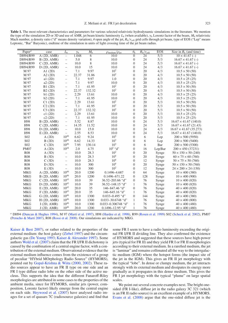
Table 1. The most relevant characteristics and parameters for various selected relativistic hydrodynamic simulations in the literature. We mentionthe type of the simulation 2D or 3D and use of AMR, jet beam kinetic luminosity Lb (when available), γb Lorentz factor of the beam, Mb relativisticMach number, η density ratio (“d” means density variation), θ open angle of the jet, Rb/rcell grid cells through jet beam, type of EOS (“Lep” meansLeptonic, “Bar” Baryonic), endtime of the simulation in units of light crossing time of the jet beam radius.
Papera case Lb γb Mb ρmedium/ρjet θb Rb/rcell EOS Size in Rb (and time)DH94/R99 A (2D, AMR) – 1.048 6 10.0 0 24 5/3 10 × 41.67 (–)DH94/R99 B (2D, AMR) – 5.0 8 10.0 0 24 5/3 16.67 × 41.67 (–)DH94/R99 C (2D, AMR) – 10.0 8 10.0 0 24 5/3 16.67 × 41.67 (–)DH94/R99 D (2D, AMR) – 10.0 15 10.0 0 24 4/3 16.67 × 41.67 (–)
M 97 A1 (2D) – 7.1 9.97 102 0 20 4/3 10.5 × 50 (50)M 97 A2 (2D) – 22.37 31.86 102 0 20 4/3 10.5 × 50 (50)M 97 a1 (2D) – 7.1 9.97 1.0 0 20 4/3 10.5 × 25 (25)M 97 a2 (2D) – 7.1 9.97 10.0 0 20 4/3 10.5 × 25 (25)M 97 B1 (2D) – 7.1 41.95 102 0 20 4/3 10.5 × 50 (50)M 97 B2 (2D) – 22.37 132.32 102 0 20 4/3 10.5 × 50 (50)M 97 b1 (2D) – 2.29 13.61 10.0 0 20 4/3 10.5 × 25 (25)M 97 b2 (2D) – 7.1 41.95 10.0 0 20 4/3 10.5 × 25 (25)M 97 C1 (2D) – 2.29 13.61 102 0 20 5/3 10.5 × 50 (50)M 97 C2 (2D) – 7.1 41.95 102 0 20 5/3 10.5 × 50 (50)M 97 C3 (2D) – 22.37 132.32 102 0 20 5/3 10.5 × 50 (50)M 97 c1 (2D) – 2.29 13.61 10.0 0 20 5/3 10.5 × 25 (25)M 97 c2 (2D) – 7.1 41.95 10.0 0 20 5/3 10.5 × 25 (25)H98 B (2D, AMR) – 5.52 8.87 10.0 0 24 5/3 16.67 × 41.67 (140.0)H98 C (2D, AMR) – 14.35 11.52 10.0 0 24 5/3 16.67 × 41.67 (21.43)H98 D (2D, AMR) – 10.0 15.0 10.0 0 24 4/3 16.67 × 41.67 (35.273)H98 E (2D, AMR) – 2.55 8.53 10.0 0 24 5/3 16.67 × 41.67 (140.0)S02 A (2D) 1046 6.62 9.24 105 0 6 Lep 200 × 500 (5950)S02 B (2D) 1046 6.62 14.33 103 0 6 Lep 200 × 500 (5400)S02 C (2D) 1046 7.95 130.14 103 0 6 Bar 200 × 500 (5300)
PM07 A (2D) 1044 2.0 4.75 105 “d" 0 16 Lep/Bar 200 × 450 (37231)R08 A (3D) – 10.0 28.3 102 0 20 Synge 50 × 150 × 50 (240)R08 B (3D) – 10.0 28.3 104 0 20 Synge 60 × 75 × 60 (760)R08 C (3D) – 10.0 28.3 104 0 12 Synge 50 × 75 × 50 (760)R08 D (3D) – 10.0 300 104 0 20 Synge 50 × 150 × 50 (760)R08 E (3D) – 10.0 300 102 0 12 Synge 24 × 200 × 24 (150)
MKG A (2D, AMR) 1046 20.0 1200 0.1496–4.687 0 64 Synge 10 × 400 (380)MKG B (2D, AMR) 1046 20.0 1200 0.1496–671.22 0 128 Synge 10 × 400 (900)MKG C (2D, AMR) 1043 10.0 39 36.52–203.66 “d” 0 76 Synge 10 × 400 (820)MKG D (2D, AMR) 1043 10.0 39 36.52–148.15 “d” 1 76 Synge 10 × 400 (820)MKG E (2D, AMR) 1043 20.0 35 146–847.46 “d” 0 76 Synge 40 × 400 (820)MKG F (2D, AMR) 1043 20.0 35 146–645.16 “d” 1 76 Synge 40 × 400 (820)MKG G (2D, AMR) 1046 10.0 1300 0.033–0.495 “d” 0 144 Synge 40 × 400 (380)MKG H (2D, AMR) 1046 10.0 1300 0.033–30.6748 “d” 1 76 Synge 40 × 400 (800)MKG I (2D, AMR) 1046 10.0 1300 0.033–0.306748 “d” 1 76 Synge 40 × 400 (480)MKG J (2D, AMR) 1046 20.0 1200 0.1496–12.95 “d” 1 76 Synge 40 × 400 (480)
a DH94 (Duncan & Hughes 1994), M 97 (Martí et al. 1997), H98 (Hardee et al. 1998), R99 (Rosen et al. 1999) S02 (Scheck et al. 2002), PM07(Perucho & Martí 2007), R08 (Rossi et al. 2008). Our simulations are indicated by MKG.
Kaiser & Best 2007), or rather related to the properties of theexternal medium: the host galaxy (Zirbel 1997) and the circum-galactic gas (De Young 1993; Kaiser & Alexander 1997). Someauthors Wold et al. (2007) claim that the FR I/FR II dichotomy iscaused by the combination of a central engine factor, with a con-tribution of the external medium. Observational evidence that theexternal medium influence comes from the existence of a groupof peculiar “HYbrid MOrphology Radio Source” (HYMORS),pointed out by Gopal-Krishna & Wiita (2000, 2002). These ra-dio sources appear to have an FR II type on one side and anFR I type diffuse radio lobe on the other side of the active nu-cleus. This supports the idea that the different Fanaroff-Rileymorphologies are attributed in some cases to the properties of theambient media, since for HYMORS, similar jets (power, com-position, Lorentz factor) likely emerge from the central engineon each side. Heywood et al. (2007) have analysed radio im-ages for a set of quasars 7C (radiosource galaxies) and find that
some FR I seem to have a radio luminosity exceeding the origi-nal FR I/FR II dividing line. They also confirmed the existenceof HYMORS and suggested that these sources have high-powerjets (typical for FR II) and they yield FR I or FR II morphologiesaccording to their external medium. In a rarefied medium, the jetis “laminar” and remains collimated all the way to the intergalac-tic medium (IGM) where the hotspot forms (the impact site ofthe jet in the IGM). This gives an FR II jet morphology withthe typical “lobe”. In dense or clumpy medium, the jet interactsstrongly with its external medium and dissipates its energy moregradually as it propagates in this dense medium. This gives theFR I jet morphology with the typical “plume” on large spatialscales.
We point out several concrete examples next. The bright one-sided (FR I-like), diffuse jet in the radio galaxy 3C 321 (whichis an FR II radio source) is an excellent example of a HYMORS.Evans et al. (2008) argue that the one-sided diffuse jet is the
324 Z. Meliani et al.: FR I jet deceleration
result of an interaction of the jet with the companion galaxy.That both sides of the jets are relativistic and stable on the par-sec scale in these objects, and the difference appears on the largescale means that the variation in the external medium must oc-cur at some distance from the central engine. This is what weassume in our models. The radio galaxy Cen A shows also a dif-ference in the radio morphology between the two sides of thejet as it propagates on kiloparsec scales, with edge-brightenedlobes (FR I-like) on one side, and on the other side a central(fine structured) lobe (FR II-like) (Kraft et al. 2003). Yet anotherexample is the powerful radio source Hercules A (3C 348) thathas a jet kinetic luminosity 1046 ergs/s (McNamara et al. 2005)and exhibits a mixed FR I/FR II morphology (Sadun & Morrison2002). These observations confirm the idea that, in Cen A andHercules A (3C 348), the external medium plays a key role in theappearance of the jet and its dynamics. There is also evidence ofdisruptions or variations in radio morphologies induced by inho-mogeneous medium; for example, the evident hierarchical struc-ture of M 87 in its radio image (Owen et al. 2000), with the pos-sibility of the existence of two haloes: an inner halo that could bewith more porous structure, while the jet interacts mainly withthe outer halo (Owen et al. 2000). In conclusion, some FR I jetspropagate through clumpy (Croft et al. 2006) or dense media,evidently encountering sudden density changes. This is knownto give rise to a strong interaction, and the jet loses its energyby entrainment and diffusion (De Young 1993, 1996; Rosen &Hardee 2000; Tavecchio et al. 2006) and also forms knots alongthe jet (Owen et al. 1989). We now explain our new, more elabo-rate model, with which we aim to explain observations of jets inradio galaxies that are relativistic on a small scale and decelerateto sub-relativistic velocities approaching the large scale.
2.1. Model
To make the problem more tractable, we assume axisymme-try and neglect the influence of the magnetic field in the dy-namics. In our scenario, we assume the existence of a densityjump in the host galaxy or in circumgalactic gas, which couldbe responsible for the jet deceleration and knot formation in theasymptotic region. Since the jets travel enormous distances, itis inevitable that they encounter various sudden transitions ofinterstellar medium properties. These could be traveling shockfronts, more gradually varying background variations as one tra-verses regions of differing gravitational potential, or contact dis-continuities indicative of boundaries between varying regions ofinfluence. We concentrate on the latter, representing density (andentropy) changes across which total force balance holds (uni-form pressure), as these are invariably found in any kind of hy-drodynamic interaction involving winds, outflows, etc.
We model jet propagation through two distinct media. In thefirst part, a low and uniform density is assumed, such that thejet-external medium interaction is weak in this region. We willtypically consider jets that are denser than the lower surround-ing medium (but also include models where the jet is alreadyunderdense in this region). If the external medium in the innerregion is denser than the jet, one expects strong disruption of thejet and hence diffuse and destabilised jets in this inner (parsecscale) region where the jet would decelerate and dissipate its en-ergy. This contrasts with observations of narrow and relativisticjets in the inner region of FR I galaxies and in the HYMORS,where the energy deposited on the large scale is comparable tothe energy of the central engine (Rawlings & Saunders 1991). Inthis work, we are particularly interested in radio loud FR I with apowerful jet at high Lorentz factor on the lower scale. This is the
case in the HYMORS, where the jets have the same propertieson small scale than the high energy FR II jets. The differencesappear only on one side of the jet on the larger scale, wherethe jet morphology changes to show a structure characteristicof an FR I. Therefore, we assume that, further downstream, thejet encounters a high-density medium, such that the jet under-goes a strong deceleration and a strong compression. This latterpart is typically the only part simulated in previous numerical jetstudies, where a prescribed jet configuration penetrates a usuallyuniform, high-density, external medium. Moreover, we study theeffect of the initial opening angle of the jet in its interaction with(layered or stratified) external medium.
For the density jump in the case of 3C 321, we can thinkof the lower region as the rarefied medium in the inter-clustermedium, while the upper region represents the denser mediumof the companion galaxy. In other HYMORS, the density jumpis then thought to occur on one side of the AGN where thereare denser molecular clouds in the inter-cluster environment orinterstellar medium. One of the main points we hereby addressfor the first time is the change in jet head properties during thepropagation phase in the inner region, and how this in turn af-fects the jet stability in the upper, denser medium. Indeed, the jetinteracts with the inner medium mainly through the bow shock,whereas the jet beam is only weakly disturbed laterally. Theshocked swept-up matter during this phase and the shocked partof the beam, both constitute a structured bow shock ahead of thebeam, and both shocked regions form a new hot layer with lowerLorentz factor, characterised by a lower Mach number. The in-teraction of this preformed, structured jet head with denser exter-nal medium in the outer region should produce a strong cocoonand backflow. This will also disturb the non-shocked jet beam asit penetrates the denser medium. This will increase the entrain-ment of ambient material through velocity shear instabilities anddecelerate the jet (De Young 1993; Perucho & Martí 2007).
2.2. Initial conditions
Deducing the precise internal properties for an FR I jet and itsenvironment from observations is a difficult task, and densitycontrasts in particular have been obtained partly on the basis ofnumerical studies. However, from generic properties of jet prop-agation in various FR I galaxies, one can estimate the kineticluminosity and the jet beam Lorentz factor. Then, the choice ofjet and environment parameters is determined base on input fromthe kinetic luminosity of the jet and the estimated jet propaga-tion speed in the two media. The kinetic luminosity of a typicalpowerful jet is Ljet,Kin ∼ 1046 ergs/s (Rawlings & Saunders 1991;Daly 1995; Carilli & Barthel 1996; Wan et al. 2000; Drake 2003;Tavecchio et al. 2004; Kino & Takahara 2004), and we used thisobservationally supported value for the simulations indicated ascases A, B, G, H, I, J (see Table 1). We also investigated thepropagation of low-energy jets and compared them with thesemore powerful jets. For more radio-quiet galaxies, a lower en-ergy jet with Ljet,Kin ∼ 1043 ergs/s (Allen et al. 2006) is deduced,and this value is used for the simulations C, D, E, F. The inte-grated energy flux over the beam cross section is computed from(e.g. Bicknell & Begelman 1996; Martí et al. 1997; Rosen et al.1999; Scheck et al. 2002)
Ljet,Kin = (γb hb − 1) ρbγbπR2bvb, (1)
where the subscript “b” indicates the jet beam, ρb its density,γb the Lorentz factor, vb the speed, ρbhb = ρb +
ΓΓ−1 pb the en-
thalpy, and Rb the jet radius. For the last, when we assumeda jet with opening angle of θb = 3◦ at 1 pc, the observed
Z. Meliani et al.: FR I jet deceleration 325
value in Centaurus A (Horiuchi et al. 2006), we got a jet radiusRb ∼ 0.05 pc. We fixed the radius Rb = 0.05 pc on our jet inputboundary, which in turn is assumed to be located at a distancefrom the source of 0.5 pc.
Furthermore, an estimated propagation speed of the head ofthe jet can be obtained from using the expression for pressure-matched jet propagation in 1D (Martí et al. 1997; Rosen et al.1999). For a cold external medium, this yields
v1Djet =
√ηR√ηR + 1
vb, (2)
where ηR = γ2bρbhb
ρmhmis the ratio between the inertia in the jet
and in the external medium. In the relativistic case, the iner-tia of the flow increases as γ2 with the speed (which makesrelativistic jets stabler than jets in young stellar objects). Ourt = 0 conditions then use the number density of the cold externalmedium in the pc-scale region set to nLow = 1 cm−3 as a scal-ing value, together with Rb as a unit of length, in combinationwith c = 1. Then, the pressure in this cold external medium isset to p = 10−3mp nLowc2, and this value for the pressure is infact taken to be equal in the jet, and also in the outer region thatis in static equilibrium with the inner region. We take the beamLorentz factor fixed at γb = 20 for the simulations A, B, E, F, Jand at γb = 10 for the simulations C, D, G, H, I. These assumedhigh inlet Lorentz factors are at the observed values appropri-ate for FR II and BL Lac objects on pc-scale (Kellermann et al.2004; Cohen et al. 2007). This is consistent with the hypothesisthat BL Lac are FR I radio galaxies observed with a small angleto the line of sight (Urry & Padovani 1995).
The density in the jet and, in principle, also the pressure,can be deduced using Eqs. (1) and (2), by imposing the jet headpropagation Lorentz factor γhead,Low in the low-density medium(in practice, this is limited by the condition to have a positivejet pressure and density). If we choose a value γhead,Low = 5(vhead,Low = 0.979796), we find a ratio between the jet beaminertia and the lower medium inertia from Eq. (2). This is inthe range ηR,Low = [2672.3, 3000] for our models with highenergy (A, B, G, H, I, J), while we have ηR,Low = [1.8, 2.7]for our models with lower energy (C, D, E, F). We anticipatefrom these inertia contrasts that the high-energy jet in the lowerregion is fairly stable and will conserve its narrow structure,while the lower energy jets will already be disturbed by the ex-ternal medium in the lower part. When we use Eq. (1) to ob-tain our computational value for the density ratio between thejet beam and the external medium on the lower scale, we findnb/nLow = 6.681 for the simulations A, B, J; nb/nLow = 29.99for the simulations G, H, I; nb/nLow = 2.738 × 10⁻² for thesimulations C, D; and finally nb/nLow = 6.82 × 10⁻³ for the sim-ulations E, F.
For the density of the external medium in the upper, down-stream region, we can argue similarly by setting a head prop-agation Lorentz factor on the kpc-scale. In this paper, we willinvestigate many cases for the upper medium conditions. In thetwo first cases (A, B), we choose a uniform density medium.In all other models, beyond the jump in the density at the in-terface between the lower and higher scale regions, the densitydecreases with distance from the source with a simple power lawZjump/
√R2 + Z2 (Kaiser & Alexander 1997). Furthermore, in
model A, we assume that the jet undergoes weak deceleration inthis upper region, where the Lorentz factor of the jet head dropsto γhead,Up = 1.5 (mildly relativistic). Then, the ratio betweenthe jet beam inertia and upper medium inertia is ηR,Up = 8.65,which increases the influence of the external medium on the jet.
Again, similar reasoning makes it plausible to use a density ra-tio nUp/njet ∼ 4.687 for the upper medium then. In model B, weconsider a very dense upper medium, expected to induce a strongdeceleration of the jet to γhead,Up = 1.02 (vhead,Up = 0.197), whichcorresponds to a sub-relativistic jet. The inertia ratio between thejet beam and the upper medium is in this case ηR,Up ∼ 0.0604,and this very low value will lead to increasing the jet-externalmedium interaction and the growth of body and surface mode in-stabilities in the jet. We find that to end up with this low Lorentzfactor in the upper high-density medium, we need to assume afairly extreme, high value of density nUp/njet ∼ 671.22. Thisis admittedly very high; however, many numerical simulationsshow that to decelerate a relativistic jet to sub-relativistic speeds,we need overdense external medium where nUp/nb > 100 andeven higher (Krause 2005). This is also seen by the exploitedvalued for the density contrast in most numerical simulations todate, as collected in Table 1. Furthermore, from Eq. (1) one canargue that for fixed luminosity, the jet density decreases with jetradius as (0.05 pc/Rb)2. This suggests that, for a bigger openingangle of the jet (hence bigger jet radius), the jet density and thusalso the upper external medium density will be lower, while thebehaviour of the jet in this region should be the same. For allother models, the density ratio at the interface reaches the val-ues indicated in Table 1, and then decreases outwards. To alsomodel the effect of conical versus cylindrical jet propagation,we assume a 1◦ opening angle at the inlet for models D, F, H, I,and J. This opening angle is taken to be smaller than the openangle of the jet at the boundary 3◦, since the jet is supposed tocollimate slowly during its propagation.
2.3. Employed resolution
In all our simulations of jet propagation, we set the lower bound-ary at Zin = 0.5
(Rb
0.05 pc
)pc and initialise the jet material within
the domain for radii R < Rb and extended to Z = 1.0(
Rb0.05 pc
)pc.
The boundary imposes a stationary mass flux at the lower bound-ary for radii R < Rb. The lower boundary for R > Rb is open.The top boundary is set at Zext and the jump in density is set ata distance Zjump = Zext/2, midway in our (very large) computa-tional domain. Note again that, as is evident from Table 1, wehere cover jet propagation over distances that go as far as 400 jetbeam radii and that have enough resolution to analyse with highaccuracy the interaction of the jet with the external medium, andthis is only feasible thanks to our AMR capabilities.
Simulation A was done on a domain with size [R, Z] ∈[0, 10] × [10, 400] (in units of Rb), with a resolution on the baselevel of 40 × 1200. Our grid-adaptive runs allow for 5 levels,achieving an effective resolution of 640 × 19 200. The secondsimulation is done on a domain with size [R, Z] ∈ [0, 40] ×[10, 400] and base level resolution of 160 × 1200; however, weallowed for 6 levels achieving an effective resolution of 57 ×38 400. This anticipates that, since the ratio between the jet beamdensity and upper medium density is very high in the secondcase, the shock in this model will be very strongs, and is likelyto produce a turbulent cocoon and jet in this region. All othercases are done on a domain with size [R, Z] ∈ [0, 40] × [10, 400]and with an effective resolution 3072 × 4800 (4 levels). All thesimulations exploit the hybrid version of HLLC, as explained inthe Appendix.
3. Discussion of results
From a basic point of view, the jet-external medium interactionis structured along the jet propagation axis in a similar way to
326 Z. Meliani et al.: FR I jet deceleration
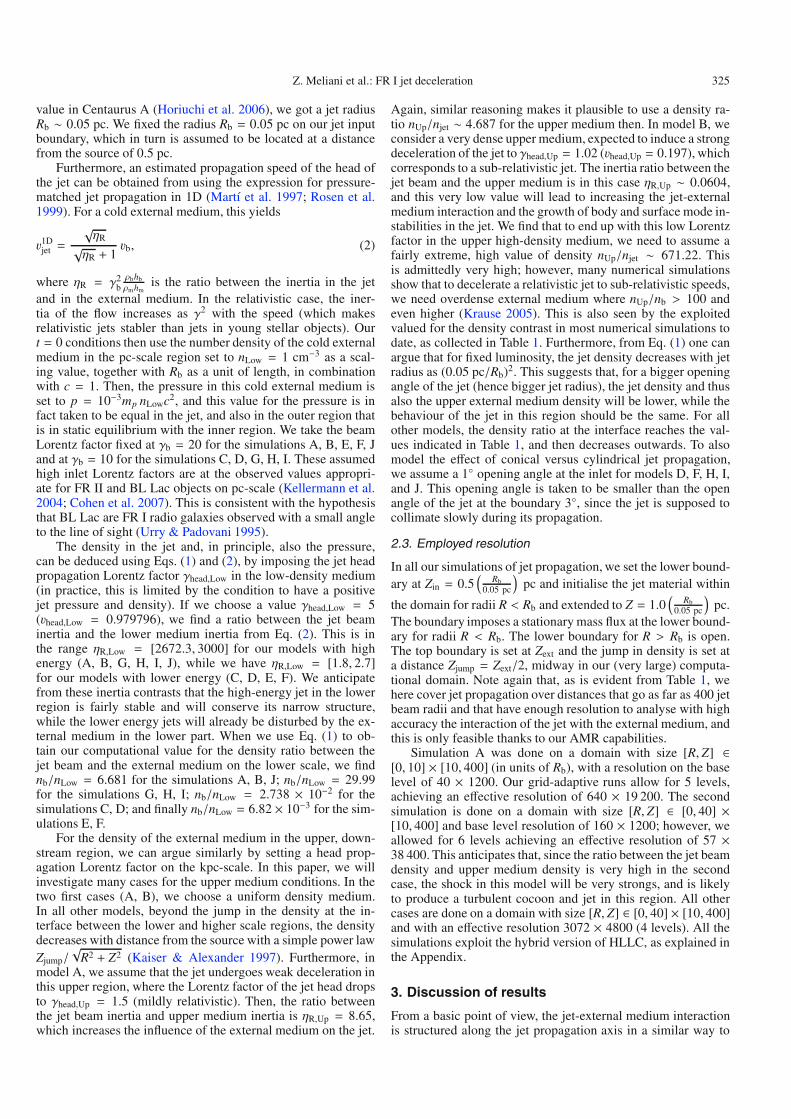
Fig. 1. A zoom on the jet head at t = 160 light crossing times of the jet radius Rb, for cases A, B, and J, just prior to penetrating the denser uppermedium. Shown are: (top) the logarithm of density, (middle) the Lorentz factor, (bottom) the effective polytropic index. In this and subsequentfigures, distances indicated on the axes are shown in parsec.
the 1D tests described in our appendix. At the head of the jet,there are the forward shock, the contact discontinuity (calledthe work surface), and the reverse shock (called the Mach disc).The forward shock compresses and heats the external medium,which spreads laterally, leading to the formation of a bow shock.The reverse shock decelerates the beam matter by converting itskinetic energy into thermal energy. However, the shapes of theMach disc and forward shock in a true 2D jet are oblique, andother 2D effects appear, which we describe in the following.
3.1. Propagation through the uniform lower region
3.1.1. Models A, B, and J
In models A, B, and J, the properties of the jet and of the lowerexternal medium are the same, and the following discussion isapplicable to these 3 cases. Prior to penetrating the dense upperregion the jet density, is seen in a close-up view in Fig. 1. Thisfigure is at time t = 160 (in units of light crossing time for the
jet beam radius). In the inner, low-density medium, the forwardshock is relativistic. The jet also interacts laterally with the ex-ternal medium, because there is a boundary shear layer. Due tothe favourable density contrast, this layer does not disturb thejet propagation in this lower region. This thin shear layer is cre-ated as the Mach disc compresses the external shell of the jet.Only near the jet head, in between working surface and reverseshock (Mach disc), and a bit beyond the reverse shock location,is the shear layer Kelvin-Helmholtz unstable (see our zoomed-inFig. 1). We hardly find any backflow from the work surface inthis lower region.
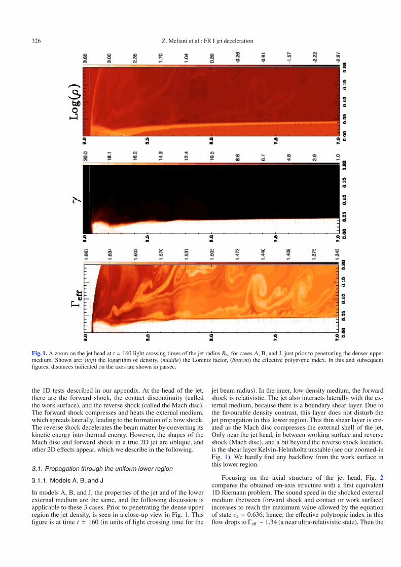
Focusing on the axial structure of the jet head, Fig. 2compares the obtained on-axis structure with a first equivalent1D Riemann problem. The sound speed in the shocked externalmedium (between forward shock and contact or work surface)increases to reach the maximum value allowed by the equationof state cs ∼ 0.636; hence, the effective polytropic index in thisflow drops to Γeff ∼ 1.34 (a near ultra-relativistic state). Then the
Z. Meliani et al.: FR I jet deceleration 327
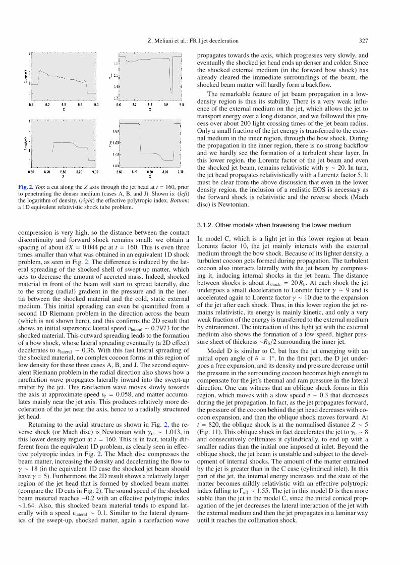
Fig. 2. Top: a cut along the Z axis through the jet head at t = 160, priorto penetrating the denser medium (cases A, B, and J). Shown is: (left)the logarithm of density, (right) the effective polytropic index. Bottom:a 1D equivalent relativistic shock tube problem.
compression is very high, so the distance between the contactdiscontinuity and forward shock remains small: we obtain aspacing of about δX = 0.044 pc at t = 160. This is even threetimes smaller than what was obtained in an equivalent 1D shockproblem, as seen in Fig. 2. The difference is induced by the lat-eral spreading of the shocked shell of swept-up matter, whichacts to decrease the amount of accreted mass. Indeed, shockedmaterial in front of the beam will start to spread laterally, dueto the strong (radial) gradient in the pressure and in the iner-tia between the shocked material and the cold, static externalmedium. This initial spreading can even be quantified from asecond 1D Riemann problem in the direction across the beam(which is not shown here), and this confirms the 2D result thatshows an initial supersonic lateral speed vlateral ∼ 0.7973 for theshocked material. This outward spreading leads to the formationof a bow shock, whose lateral spreading eventually (a 2D effect)decelerates to vlateral ∼ 0.36. With this fast lateral spreading ofthe shocked material, no complex cocoon forms in this region oflow density for these three cases A, B, and J. The second equiv-alent Riemann problem in the radial direction also shows how ararefaction wave propagates laterally inward into the swept-upmatter by the jet. This rarefaction wave moves slowly towardsthe axis at approximate speed vr = 0.058, and matter accumu-lates mainly near the jet axis. This produces relatively more de-celeration of the jet near the axis, hence to a radially structuredjet head.
Returning to the axial structure as shown in Fig. 2, the re-verse shock (or Mach disc) is Newtonian with γrs ∼ 1.013, inthis lower density region at t = 160. This is in fact, totally dif-ferent from the equivalent 1D problem, as clearly seen in effec-tive polytropic index in Fig. 2. The Mach disc compresses thebeam matter, increasing the density and decelerating the flow toγ ∼ 18 (in the equivalent 1D case the shocked jet beam shouldhave γ = 5). Furthermore, the 2D result shows a relatively largerregion of the jet head that is formed by shocked beam matter(compare the 1D cuts in Fig. 2). The sound speed of the shockedbeam material reaches ∼0.2 with an effective polytropic index∼1.64. Also, this shocked beam material tends to expand lat-erally with a speed vlateral ∼ 0.1. Similar to the lateral dynam-ics of the swept-up, shocked matter, again a rarefaction wave
propagates towards the axis, which progresses very slowly, andeventually the shocked jet head ends up denser and colder. Sincethe shocked external medium (in the forward bow shock) hasalready cleared the immediate surroundings of the beam, theshocked beam matter will hardly form a backflow.
The remarkable feature of jet beam propagation in a low-density region is thus its stability. There is a very weak influ-ence of the external medium on the jet, which allows the jet totransport energy over a long distance, and we followed this pro-cess over about 200 light-crossing times of the jet beam radius.Only a small fraction of the jet energy is transferred to the exter-nal medium in the inner region, through the bow shock. Duringthe propagation in the inner region, there is no strong backflowand we hardly see the formation of a turbulent shear layer. Inthis lower region, the Lorentz factor of the jet beam and eventhe shocked jet beam, remains relativistic with γ ∼ 20. In turn,the jet head propagates relativistically with a Lorentz factor 5. Itmust be clear from the above discussion that even in the lowerdensity region, the inclusion of a realistic EOS is necessary asthe forward shock is relativistic and the reverse shock (Machdisc) is Newtonian.
3.1.2. Other models when traversing the lower medium
In model C, which is a light jet in this lower region at beamLorentz factor 10, the jet mainly interacts with the externalmedium through the bow shock. Because of its lighter density, aturbulent cocoon gets formed during propagation. The turbulentcocoon also interacts laterally with the jet beam by compress-ing it, inducing internal shocks in the jet beam. The distancebetween shocks is about λshock = 20 Rb. At each shock the jetundergoes a small deceleration to Lorentz factor γ ∼ 9 and isaccelerated again to Lorentz factor γ ∼ 10 due to the expansionof the jet after each shock. Thus, in this lower region the jet re-mains relativistic, its energy is mainly kinetic, and only a veryweak fraction of the energy is transferred to the external mediumby entrainment. The interaction of this light jet with the externalmedium also shows the formation of a low speed, higher pres-sure sheet of thickness ∼Rb/2 surrounding the inner jet.
Model D is similar to C, but has the jet emerging with aninitial open angle of θ = 1◦. In the first part, the D jet under-goes a free expansion, and its density and pressure decrease untilthe pressure in the surrounding cocoon becomes high enough tocompensate for the jet’s thermal and ram pressure in the lateraldirection. One can witness that an oblique shock forms in thisregion, which moves with a slow speed v ∼ 0.3 that decreasesduring the jet propagation. In fact, as the jet propagates forward,the pressure of the cocoon behind the jet head decreases with co-coon expansion, and then the oblique shock moves forward. Att = 820, the oblique shock is at the normalised distance Z ∼ 5(Fig. 11). This oblique shock in fact decelerates the jet to γb ∼ 8and consecutively collimates it cylindrically, to end up with asmaller radius than the initial one imposed at inlet. Beyond theoblique shock, the jet beam is unstable and subject to the devel-opment of internal shocks. The amount of the matter entrainedby the jet is greater than in the C case (cylindrical inlet). In thispart of the jet, the internal energy increases and the state of thematter becomes mildly relativistic with an effective polytropicindex falling to Γeff ∼ 1.55. The jet in this model D is then morestable than the jet in the model C, since the initial conical prop-agation of the jet decreases the lateral interaction of the jet withthe external medium and then the jet propagates in a laminar wayuntil it reaches the collimation shock.
328 Z. Meliani et al.: FR I jet deceleration
Model E only differs from C in its twice higher beam Lorentzfactor. It has an inertia ratio between jet-external medium of asimilar order to model C. Despite the faster jet beam, its Lorentzfactor along the beam in the first region ends up oscillating be-tween 10−25 due to the successive internal shocks and jet ex-pansions, such that the jets in both model show the same gen-eral behaviour. In the model F, the E (cylindrical) jet modelnow emerges conically with an initial open angle of θ = 1◦.Its Lorentz factor γb = 20 and kinetic luminosity LJet,Kin =1043 ergs/s mean that the difference with the conical model D isa faster jet. In this model F, the forward shock that forms at thejet head is stronger, producing higher pressure and a more ex-tended cocoon. This cocoon limits the region of the free conicalexpansion of the jet by forming oblique shocks that recollimatethe jet. This oblique shock in model F propagates with a speedv ∼ 0.1, which is lower than the speed of the oblique shock inmodel D. As in model D, the speed of the oblique shock de-creases during the propagation. Beyond this oblique shock, theLorentz factor of the jet decreases to about 10, and the jet startsto be unstable with the formation of internal shocks that com-press and induces consecutive acceleration and deceleration ofthe jet. In this region, the state of the matter in the jet is relativis-tic with an effective polytropic index Γeff ∼ 1.45. At t = 820, theoblique shock is at a normalised distance Z ∼ 7.5 (Fig. 11).
In model G, the interaction between the jet and the externalmedium is roughly the same as in model A, because only theLorentz factor of the jet beam changes from γ = 20 in model Ato γ = 10. In fact, the main differences between the two modelsis in the details of the structure of the jet head, since the rateof compression at the front shock and the Mach disc (reverseshock) is different. In any case, the jet interacts weakly laterallywith the external medium and it remains stable, consistent withits higher density with respect to the surroundings. Finally, in theconical models H and I (otherwise similar to G and also of highenergy), the jet only interacts with external medium through theshock in front, and there is no lateral interaction between the jetand the external medium, as only the head of the jet is slightlycollimated. In fact, the conical propagation of the jet decreasesthe influence of the low-density external medium on the jet.
3.1.3. Summary for the lower region
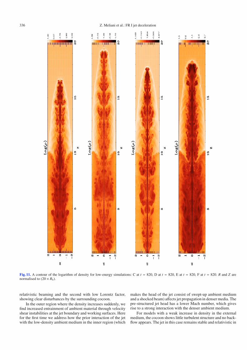
In the lower region, the jet head propagates with a speedvhead,Low ∼ 0.6 for the models C, D, E, F, and with a speedvhead,Lows ∼ 0.99 in the models A, B, G, H, I, J, as also collectedin Fig. 12. In fact, these two groups are clearly distinct from the(input) kinetic luminosity of the jet beam. The low-energy firstgroup finds the lighter density jets interacting strongly with theexternal medium and slowing down, since the power of the jetbeam in this group is Ljet,Kin ∼ 1043 ergs/s, and then the inertiaratio between the jet and the external medium is low, and at mostabout ηR ∼ 2.73. For the second high-energy group, the exter-nal medium influences the jet weakly, since the power of the jetbeam is Ljet,Kin ∼ 1046 ergs/s and then the inertia ratio betweenthe jet and the external medium is high, up to about ηR ∼ 3000.Thus the variation in the Lorentz factor 10 to 20 of the jet beamand the small variation in the opening angle of the jet (cylindri-cal case versus conical with a small opening angle 1◦) do notsignificantly influence the speed of propagation of the jet headin the lower scale region, which is simulated here up to 200 jetradii. While we have pointed out various aspects that are clearlycaptured only using a relatistic EOS model, our findings for jetpropagation through the uniform, lower region are fully consis-tent with earlier works.
3.2. Upper region propagation
3.2.1. Model A
We now turn to the second stage in the dynamics, after the jethas passed the density jump. In model A, the density ratio be-tween the jet and upper external medium suddenly changes toρUp/ρb ∼ 4.687, making it a light jet. In this denser upper region,the initial interaction between the jet and dense upper medium isshown in a zoomed Fig. 3 at time t = 240. First, as the jet pene-trates the denser medium, an oblique shock propagates laterallyin the upper medium. The relatively higher density of the uppermedium gives rise to reflection of this shocked matter, thus pro-ducing a somewhat more turbulent and hot cocoon. At the jetsurface, a thin, rarefied, and very hot region develops (seen bestin the low effective polytropic index in Fig. 3). In fact, the headof the jet now sweeps more matter up, enhancing the tempera-ture. The high pressure in this region in turn gives rise to anotheroblique shock, which is weaker but propagates upstream and to-ward the axis. This confines the jet. This shock is located at timet = 240 at about Z ∼ 9.8. The jet radius drops due to this com-pression to about R = 0.03.
Again we can learn from the analogous 1D Riemann prob-lem and compare it with the axial structure of the 2D result.This is done in Fig. 4, at a time corresponding to Fig. 3. Asa 1D shock-structured jet head penetrates in the high-densitymedium in an upper region, there are in fact four layers ofshocked material that can be distinguished along the beam axis.Once the previously formed forward (bow) shock meets up withthe density jump, a new forward shock develops that seper-ates swept-up high-density external medium from static externalmedium. A second contact or work surface from then on seper-ates shocked high-density matter from then previously swept-up, shocked, lower-density matter. From this same location, anew reverse shock forms that traverses the previously formedstructured jet head (i.e. consisting of shocked lower matter andshocked beam matter and ending with the old Mach disc or re-verse shock). These add up to 5 discontinuities in total, whichare clearly seen in the analogous 1D problem shown in Fig. 4.However, the 2D jet propagation is different from this 1D model.The difference is quantified in Fig. 4, as we draw the cut alongthe Z axis (middle row), and also at a fixed radial distance awayfrom the axis at R = 0.02 (bottom). The latter radius still remainsin the jet “spine”, since the laterally bounding shear region thatwe also can detect in our jet beam variation extends from 0.025to 0.03 parsec.
We can clearly see that, when comparing these three cases,we find faster beam flows immediately behind the front shock in2D, which are also relativistic with a Lorentz factor γ ∼ 4. Thisis accompanied by strong compression, as the effective poly-tropic index drops to Γeff ∼ 1.37. This is like the 1D case. Tobe precise, at time t = 240, the front shock reaches a distanceZ ∼ 12.75 pc in the 2D case, where the 1D reaches Z ∼ 12.8.Various internal shocks develop behind the front shock in the2D case, partly induced by the initial structure of the jet beamwith its interaction with the denser medium. At each new obliqueshock, the flow undergoes a weak acceleration behind it. In theregion of the shocked beam, the Lorentz factor along the axisoscillates between γmin ∼ 16 and γmax ∼ 18. Then, the trail-ing reverse shock (Mach disc) and other shocks in front of it areNewtonian along the axis, and the effective polytropic index os-cillates between Γeff,min ∼ 1.65 and Γeff,max ∼ 1.61. In contrast,along the spine at fixed radius R = 0.02, the reverse shock (Machdisc) and all shocks in front of it are stronger. In fact, the Machdisc is near-Newtonian (effective polytropic index Γeff ∼ 1.58),
Z. Meliani et al.: FR I jet deceleration 329
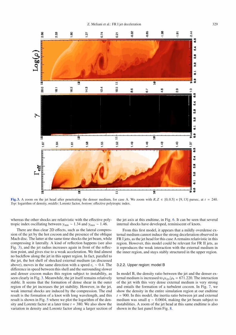
Fig. 3. A zoom on the jet head after penetrating the denser medium, for case A. We zoom with R,Z ∈ [0, 0.5] × [9, 13] parsec, at t = 240.Top: logarithm of density, middle: Lorentz factor, bottom: effective polytropic index.
whereas the other shocks are relativistic with the effective poly-tropic index oscillating between γmin ∼ 1.34 and γmax ∼ 1.46.
There are thus clear 2D effects, such as the lateral compres-sion of the jet by the hot cocoon and the presence of the obliqueMach disc. The latter at the same time shocks the jet beam, whilecompressing it laterally. A kind of reflection happens (see alsoFig. 3), and the jet radius increases again in front of the reflec-tion point, and gives rise to a weak acceleration. We find almostno backflow along the jet in this upper region. In fact, parallel tothe jet, the hot shell of shocked external medium (as discussedabove), moves in the same direction with a speed vz ∼ 0.4. Thedifference in speed between this shell and the surrounding slowerand denser cocoon makes this region subject to instability, asseen clearly in Fig. 3. Meanwhile, the jet itself remains relativelystable. It seems that the formation of dense shear in the outerregion of the jet increases the jet stability. However, in the jet,weak internal shocks are induced by the compression. The endresult is the formation of a knot with long wavelength, and thisresult is shown in Fig. 5 where we plot the logarithm of the den-sity and Lorentz factor at a later time t = 380. We also show thevariation in density and Lorentz factor along a larger section of
the jet axis at this endtime, in Fig. 6. It can be seen that severalinternal shocks have developed, reminiscent of knots.
From this first model, it appears that a mildly overdense ex-ternal medium cannot induce the strong deceleration observed inFR I jets, as the jet head for this case A remains relativistic in thisregion. However, this model could be relevant for FR II jets, asit reproduces the weak interaction with the external medium inthe inner region, and stays stably structured in the upper region.
3.2.2. Upper region: model B
In model B, the density ratio between the jet and the denser ex-ternal medium is increased to ρUp/ρb = 671.220. The interactionof the jet with this very dense external medium is very strongand entails the formation of a turbulent cocoon. In Fig. 7, weshow the density in the entire simulation region at our endtimet = 900. In this model, the inertia ratio between jet and externalmedium was small η ∼ 0.0604, making the jet beam subject toinstabilities. A zoom of the jet head at this same endtime is alsoshown in the last panel from Fig. 8.

330 Z. Meliani et al.: FR I jet deceleration
Fig. 4. Case A in the upper medium. Left: logarithm of density, centre: effective polytropic index. Right: the Lorentz factor, at time t = 240, i.e.after penetrating the denser medium. The three rows correspond to: (top) a 1D equivalent relativistic shock problem, (middle) a cut along the Z axis(i.e. R = 0) through the jet head, and (bottom) a cut along the axis at a radius R = 0.02. From the top to the bottom, note the difference in scale:Z ∈ [12.0, 13.0] for top and middle, while bottom panel has Z ∈ [11.0, 13.0].
Fig. 5. A zoom on the jet head with R,Z ∈ [0, 0.2]× [17.5, 20], at t = 380, for case A. (Top) Logarithm of density, (middle) Lorentz factor, (bottom)effective polytropic index.
Z. Meliani et al.: FR I jet deceleration 331
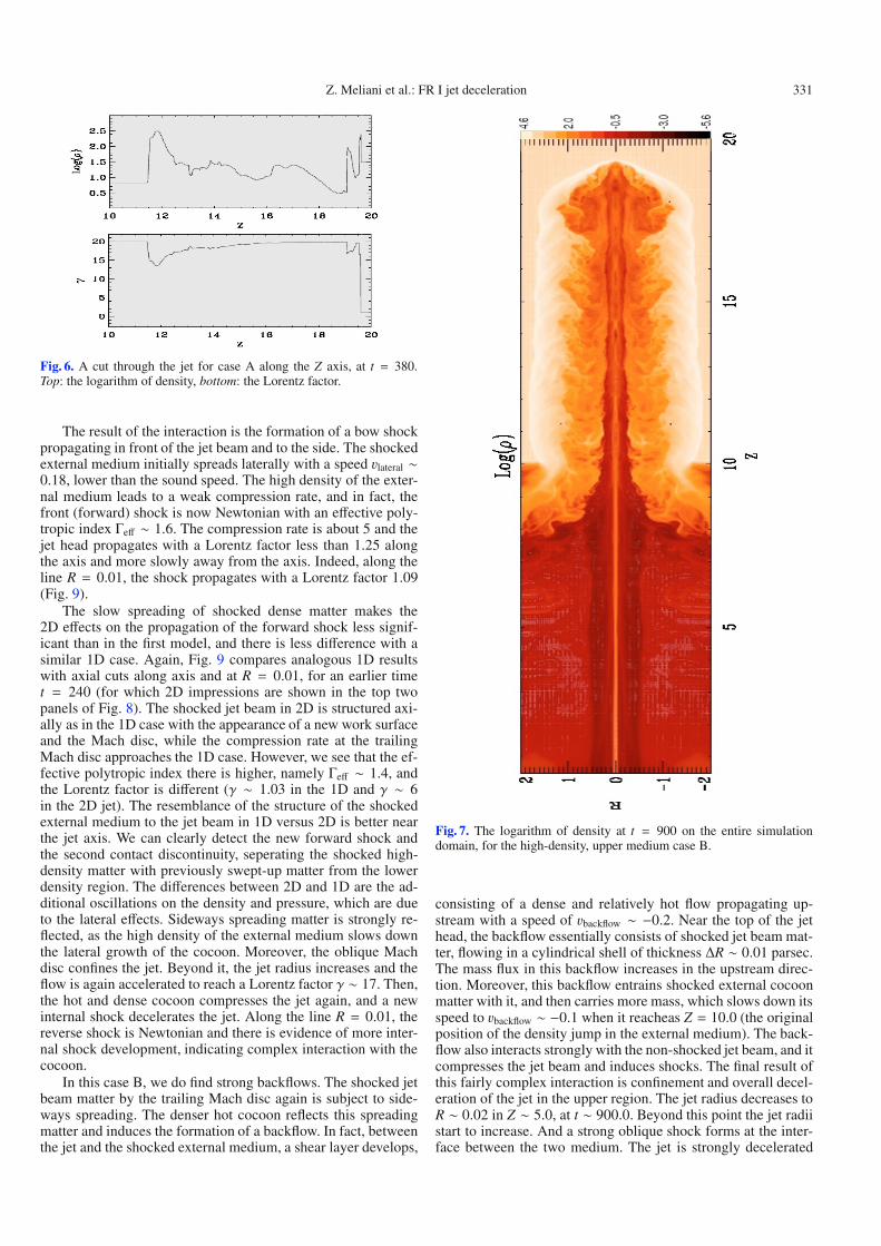
Fig. 6. A cut through the jet for case A along the Z axis, at t = 380.Top: the logarithm of density, bottom: the Lorentz factor.
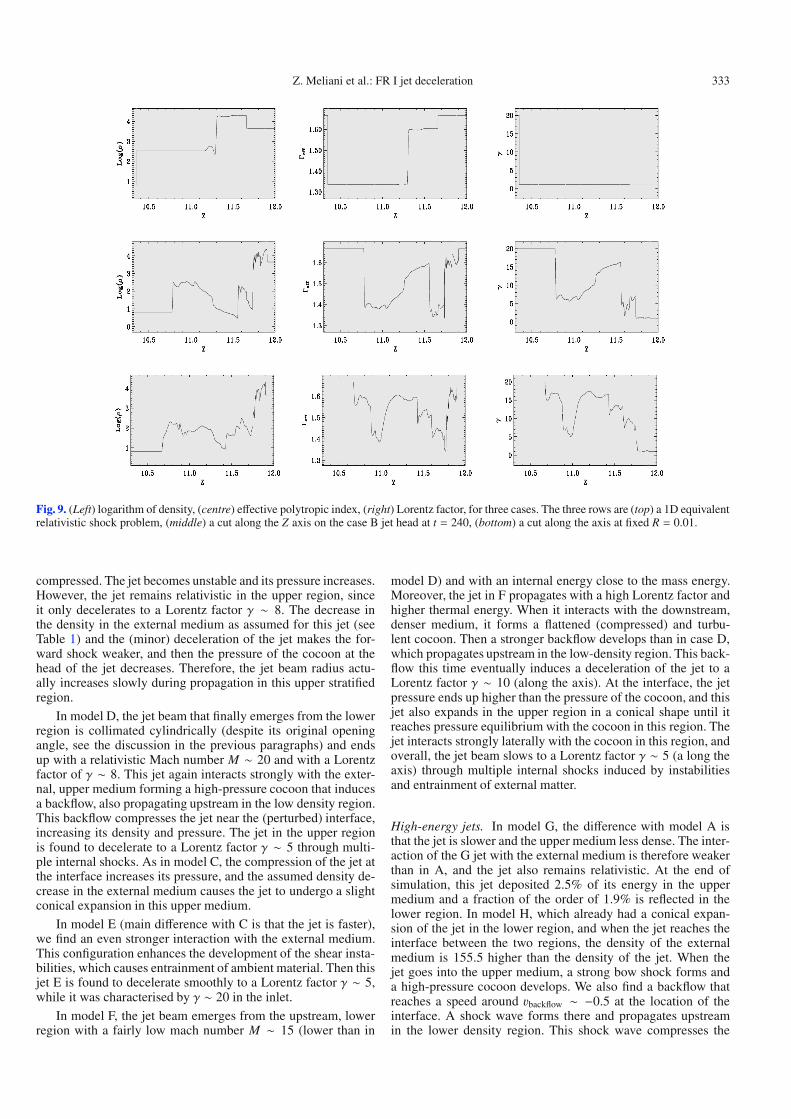
The result of the interaction is the formation of a bow shockpropagating in front of the jet beam and to the side. The shockedexternal medium initially spreads laterally with a speed vlateral ∼0.18, lower than the sound speed. The high density of the exter-nal medium leads to a weak compression rate, and in fact, thefront (forward) shock is now Newtonian with an effective poly-tropic index Γeff ∼ 1.6. The compression rate is about 5 and thejet head propagates with a Lorentz factor less than 1.25 alongthe axis and more slowly away from the axis. Indeed, along theline R = 0.01, the shock propagates with a Lorentz factor 1.09(Fig. 9).
The slow spreading of shocked dense matter makes the2D effects on the propagation of the forward shock less signif-icant than in the first model, and there is less difference with asimilar 1D case. Again, Fig. 9 compares analogous 1D resultswith axial cuts along axis and at R = 0.01, for an earlier timet = 240 (for which 2D impressions are shown in the top twopanels of Fig. 8). The shocked jet beam in 2D is structured axi-ally as in the 1D case with the appearance of a new work surfaceand the Mach disc, while the compression rate at the trailingMach disc approaches the 1D case. However, we see that the ef-fective polytropic index there is higher, namely Γeff ∼ 1.4, andthe Lorentz factor is different (γ ∼ 1.03 in the 1D and γ ∼ 6in the 2D jet). The resemblance of the structure of the shockedexternal medium to the jet beam in 1D versus 2D is better nearthe jet axis. We can clearly detect the new forward shock andthe second contact discontinuity, seperating the shocked high-density matter with previously swept-up matter from the lowerdensity region. The differences between 2D and 1D are the ad-ditional oscillations on the density and pressure, which are dueto the lateral effects. Sideways spreading matter is strongly re-flected, as the high density of the external medium slows downthe lateral growth of the cocoon. Moreover, the oblique Machdisc confines the jet. Beyond it, the jet radius increases and theflow is again accelerated to reach a Lorentz factor γ ∼ 17. Then,the hot and dense cocoon compresses the jet again, and a newinternal shock decelerates the jet. Along the line R = 0.01, thereverse shock is Newtonian and there is evidence of more inter-nal shock development, indicating complex interaction with thecocoon.
In this case B, we do find strong backflows. The shocked jetbeam matter by the trailing Mach disc again is subject to side-ways spreading. The denser hot cocoon reflects this spreadingmatter and induces the formation of a backflow. In fact, betweenthe jet and the shocked external medium, a shear layer develops,
Fig. 7. The logarithm of density at t = 900 on the entire simulationdomain, for the high-density, upper medium case B.
consisting of a dense and relatively hot flow propagating up-stream with a speed of vbackflow ∼ −0.2. Near the top of the jethead, the backflow essentially consists of shocked jet beam mat-ter, flowing in a cylindrical shell of thickness ΔR ∼ 0.01 parsec.The mass flux in this backflow increases in the upstream direc-tion. Moreover, this backflow entrains shocked external cocoonmatter with it, and then carries more mass, which slows down itsspeed to vbackflow ∼ −0.1 when it reacheas Z = 10.0 (the originalposition of the density jump in the external medium). The back-flow also interacts strongly with the non-shocked jet beam, and itcompresses the jet beam and induces shocks. The final result ofthis fairly complex interaction is confinement and overall decel-eration of the jet in the upper region. The jet radius decreases toR ∼ 0.02 in Z ∼ 5.0, at t ∼ 900.0. Beyond this point the jet radiistart to increase. And a strong oblique shock forms at the inter-face between the two medium. The jet is strongly decelerated

332 Z. Meliani et al.: FR I jet deceleration
Fig. 8. A zoom on the jet head after penetrating the high-density medium in case B, for R,Z ∈ [0, 0.2] × [9, 12] top and middle panel show att = 240: (top) Logarithm of density, (middle) Lorentz factor. Bottom panel shows, later at t = 300, the effective polytropic index, zoomed withR,Z ∈ [0, 0.3] × [10.5, 13.5].
at this shock to γ ∼ 2.0 and the pressure increases, such that therelativistic mach number falls to M ∼ 5. The high-pressure jetexpand laterally in this region to a radius R ∼ 6 × Rjet,b.
The interaction of the backflow with the shocked ex-ternal medium in the cocoon induces the development ofKelvin-Helmholtz instabilities. This is the result of the veloc-ity gradient between the backflow and the cocoon, and also oc-curs because the backflow is slightly underdense with respectto the cocoon. It is clear from Fig. 8 that the entire region ishighly structured due to instability development. In this upperregion, the density ratio was ρUp/ρb = 671.220, and we indeedfind a transition to a beam suddenly traveling at a Lorentz fac-tor of γUp ∼ 1.25. This value is a bit higher than the value usedfor setting up the initial condition (where we used 1.02). Thisdifference can be explained, by the head of the jet beam beingmade up of hot swept-up matter and hot shocked beam mat-ter, while the estimate assumed cold conditions. Moreover, inthis upper region, the forward bow shock is now Newtonian.The various layers at the head of the jet give rise to strong
turbulence development. A result of this interaction and the en-trainment of the externa matter by the jet is the deceleration ofthe jet in the upper region to γ ∼ 1.5 (v ∼ 0.3).
When estimating the overall energy budget, we find that inthe jet interaction with the upper medium, about 58% of the jetenergy gets deposited in the upper lobe, while a fraction around10% is reflected in the lower region.
3.2.3. Other cases: effects of opening angle and densitydecrease
Low-energy jets. In model C, the density ratio between the jetand the dense external medium is ρb/ρUp = 4.91× 10⁻³. There isstrong interaction of this light jet with the external medium, andthis implies the formation of a high-pressure cocoon. This turbu-lent cocoon disturbs the jet by inducing a strong backflow. Thedifference in pressure between turbulent cocoon and the colderlower region also produces backflows propagating into the lowerregion. At the interface between the two regions, the jet beam is
Z. Meliani et al.: FR I jet deceleration 333
Fig. 9. (Left) logarithm of density, (centre) effective polytropic index, (right) Lorentz factor, for three cases. The three rows are (top) a 1D equivalentrelativistic shock problem, (middle) a cut along the Z axis on the case B jet head at t = 240, (bottom) a cut along the axis at fixed R = 0.01.
compressed. The jet becomes unstable and its pressure increases.However, the jet remains relativistic in the upper region, sinceit only decelerates to a Lorentz factor γ ∼ 8. The decrease inthe density in the external medium as assumed for this jet (seeTable 1) and the (minor) deceleration of the jet makes the for-ward shock weaker, and then the pressure of the cocoon at thehead of the jet decreases. Therefore, the jet beam radius actu-ally increases slowly during propagation in this upper stratifiedregion.
In model D, the jet beam that finally emerges from the lowerregion is collimated cylindrically (despite its original openingangle, see the discussion in the previous paragraphs) and endsup with a relativistic Mach number M ∼ 20 and with a Lorentzfactor of γ ∼ 8. This jet again interacts strongly with the exter-nal, upper medium forming a high-pressure cocoon that inducesa backflow, also propagating upstream in the low density region.This backflow compresses the jet near the (perturbed) interface,increasing its density and pressure. The jet in the upper regionis found to decelerate to a Lorentz factor γ ∼ 5 through multi-ple internal shocks. As in model C, the compression of the jet atthe interface increases its pressure, and the assumed density de-crease in the external medium causes the jet to undergo a slightconical expansion in this upper medium.
In model E (main difference with C is that the jet is faster),we find an even stronger interaction with the external medium.This configuration enhances the development of the shear insta-bilities, which causes entrainment of ambient material. Then thisjet E is found to decelerate smoothly to a Lorentz factor γ ∼ 5,while it was characterised by γ ∼ 20 in the inlet.
In model F, the jet beam emerges from the upstream, lowerregion with a fairly low mach number M ∼ 15 (lower than in
model D) and with an internal energy close to the mass energy.Moreover, the jet in F propagates with a high Lorentz factor andhigher thermal energy. When it interacts with the downstream,denser medium, it forms a flattened (compressed) and turbu-lent cocoon. Then a stronger backflow develops than in case D,which propagates upstream in the low-density region. This back-flow this time eventually induces a deceleration of the jet to aLorentz factor γ ∼ 10 (along the axis). At the interface, the jetpressure ends up higher than the pressure of the cocoon, and thisjet also expands in the upper region in a conical shape until itreaches pressure equilibrium with the cocoon in this region. Thejet interacts strongly laterally with the cocoon in this region, andoverall, the jet beam slows to a Lorentz factor γ ∼ 5 (a long theaxis) through multiple internal shocks induced by instabilitiesand entrainment of external matter.
High-energy jets. In model G, the difference with model A isthat the jet is slower and the upper medium less dense. The inter-action of the G jet with the external medium is therefore weakerthan in A, and the jet also remains relativistic. At the end ofsimulation, this jet deposited 2.5% of its energy in the uppermedium and a fraction of the order of 1.9% is reflected in thelower region. In model H, which already had a conical expan-sion of the jet in the lower region, and when the jet reaches theinterface between the two regions, the density of the externalmedium is 155.5 higher than the density of the jet. When thejet goes into the upper medium, a strong bow shock forms anda high-pressure cocoon develops. We also find a backflow thatreaches a speed around vbackflow ∼ −0.5 at the location of theinterface. A shock wave forms there and propagates upstreamin the lower density region. This shock wave compresses the
334 Z. Meliani et al.: FR I jet deceleration
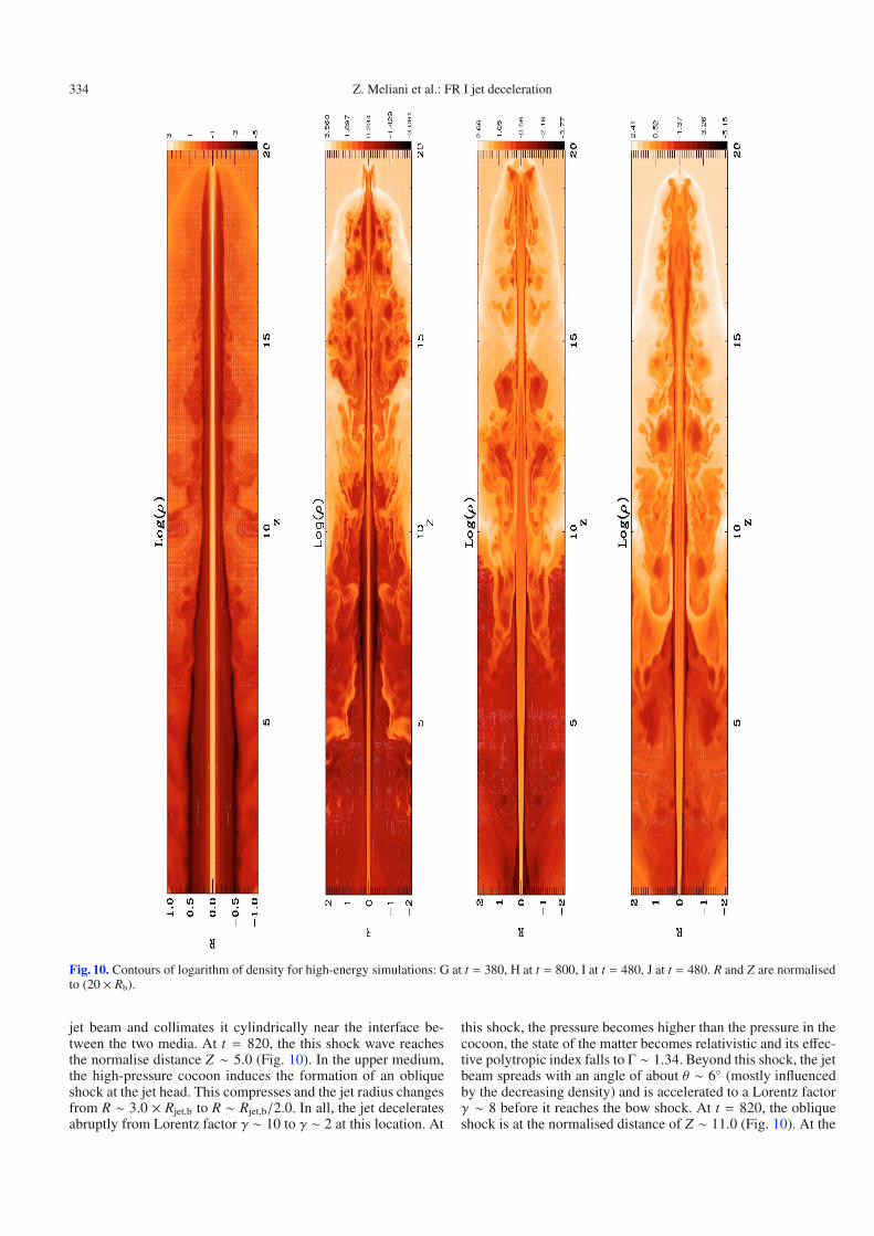
Fig. 10. Contours of logarithm of density for high-energy simulations: G at t = 380, H at t = 800, I at t = 480, J at t = 480. R and Z are normalisedto (20 × Rb).
jet beam and collimates it cylindrically near the interface be-tween the two media. At t = 820, the this shock wave reachesthe normalise distance Z ∼ 5.0 (Fig. 10). In the upper medium,the high-pressure cocoon induces the formation of an obliqueshock at the jet head. This compresses and the jet radius changesfrom R ∼ 3.0 × Rjet,b to R ∼ Rjet,b/2.0. In all, the jet deceleratesabruptly from Lorentz factor γ ∼ 10 to γ ∼ 2 at this location. At
this shock, the pressure becomes higher than the pressure in thecocoon, the state of the matter becomes relativistic and its effec-tive polytropic index falls to Γ ∼ 1.34. Beyond this shock, the jetbeam spreads with an angle of about θ ∼ 6◦ (mostly influencedby the decreasing density) and is accelerated to a Lorentz factorγ ∼ 8 before it reaches the bow shock. At t = 820, the obliqueshock is at the normalised distance of Z ∼ 11.0 (Fig. 10). At the
Z. Meliani et al.: FR I jet deceleration 335
end of simulation, the H jet deposited 40% of its energy in theupper lobe and a 16% fraction is reflected in the lower region.
In model I, the difference with the model H is that the uppermedium is less dense than the jet. In the initial period, the jet in-teracts with the external medium mainly through the front shockuntil the bow shock starts to develop prominently in the upper re-gion and its pressure increases. The high pressure of the cocooncompresses the jet and induces an internal shock in the jet thatcollimates it. Beyond this shock, the jet becomes unstable andmultiple shocks develop, decelerating the jet to Lorentz factorγ ∼ 8. At t = 480, the oblique shock is at the normalised dis-tance Z ∼ 14.0 (Fig. 10). At the end of simulation, this I jet de-posited 18% of its energy in the upper lobe and a fraction about8% is reflected in the lower region.
In model J, the jet is faster than model H (Lorentz factor 20on inlet) and the external upper medium has a density 2.5 lowerthan in model H. The initial phase of the interaction of the jetwith the upper external medium also produces a shock wavepropagating upstream, collimating the jet cylindrically. Similarto model H, the high-pressure cocoon that develops in the upperregion causes a backflow that propagates upstream. This disturbsthe jet there and induces the formation of an oblique shock thatcompresses, collimates, and decelerates the jet. In fact, at theshock, the jet radius now falls from R ∼ 4.0 × Rjet,b to R ∼ Rjet,b.The jet is decelerated to a Lorentz factor γ ∼ 10 through theshock. Beyond this, the jet spreads again and undergoes multi-ple internal shocks. Ultimately, this decelerates the jet beam tothe Lorentz factor γ ∼ 5. At t = 480, the oblique shock is at thenormalised distance Z ∼ 12.5 (Fig. 10). The faster jet J prop-agates for a longer distance than the jet in H. In fact, jet J tra-verses a longer distance in free ballistical propagation since theram pressure in the jet beam is higher. Then the oblique shockforms farther away than in H, and its overall compression rate islower. At the end of simulation, the jet deposited about 18% ofits energy in the upper lobe and a fraction 12% gets reflected.
3.2.4. Summary of all cases
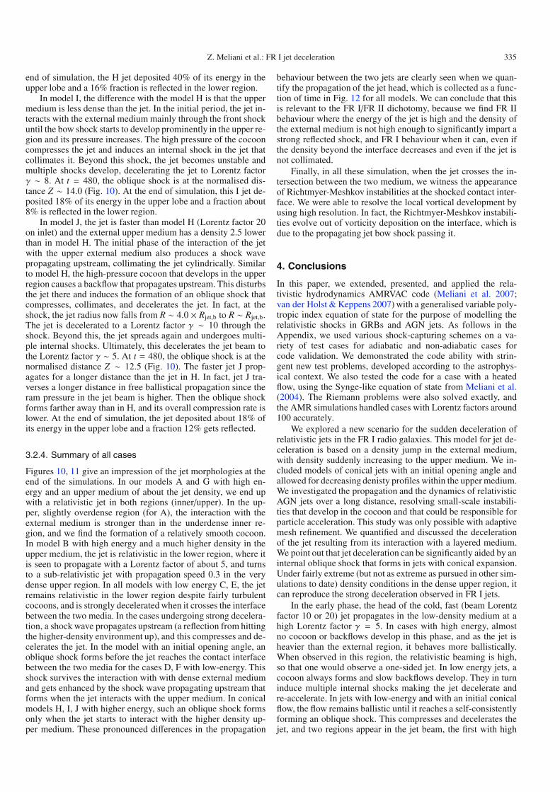
Figures 10, 11 give an impression of the jet morphologies at theend of the simulations. In our models A and G with high en-ergy and an upper medium of about the jet density, we end upwith a relativistic jet in both regions (inner/upper). In the up-per, slightly overdense region (for A), the interaction with theexternal medium is stronger than in the underdense inner re-gion, and we find the formation of a relatively smooth cocoon.In model B with high energy and a much higher density in theupper medium, the jet is relativistic in the lower region, where itis seen to propagate with a Lorentz factor of about 5, and turnsto a sub-relativistic jet with propagation speed 0.3 in the verydense upper region. In all models with low energy C, E, the jetremains relativistic in the lower region despite fairly turbulentcocoons, and is strongly decelerated when it crosses the interfacebetween the two media. In the cases undergoing strong decelera-tion, a shock wave propagates upstream (a reflection from hittingthe higher-density environment up), and this compresses and de-celerates the jet. In the model with an initial opening angle, anoblique shock forms before the jet reaches the contact interfacebetween the two media for the cases D, F with low-energy. Thisshock survives the interaction with with dense external mediumand gets enhanced by the shock wave propagating upstream thatforms when the jet interacts with the upper medium. In conicalmodels H, I, J with higher energy, such an oblique shock formsonly when the jet starts to interact with the higher density up-per medium. These pronounced differences in the propagation
behaviour between the two jets are clearly seen when we quan-tify the propagation of the jet head, which is collected as a func-tion of time in Fig. 12 for all models. We can conclude that thisis relevant to the FR I/FR II dichotomy, because we find FR IIbehaviour where the energy of the jet is high and the density ofthe external medium is not high enough to significantly impart astrong reflected shock, and FR I behaviour when it can, even ifthe density beyond the interface decreases and even if the jet isnot collimated.
Finally, in all these simulation, when the jet crosses the in-tersection between the two medium, we witness the appearanceof Richtmyer-Meshkov instabilities at the shocked contact inter-face. We were able to resolve the local vortical development byusing high resolution. In fact, the Richtmyer-Meshkov instabili-ties evolve out of vorticity deposition on the interface, which isdue to the propagating jet bow shock passing it.
4. Conclusions
In this paper, we extended, presented, and applied the rela-tivistic hydrodynamics AMRVAC code (Meliani et al. 2007;van der Holst & Keppens 2007) with a generalised variable poly-tropic index equation of state for the purpose of modelling therelativistic shocks in GRBs and AGN jets. As follows in theAppendix, we used various shock-capturing schemes on a va-riety of test cases for adiabatic and non-adiabatic cases forcode validation. We demonstrated the code ability with strin-gent new test problems, developed according to the astrophys-ical context. We also tested the code for a case with a heatedflow, using the Synge-like equation of state from Meliani et al.(2004). The Riemann problems were also solved exactly, andthe AMR simulations handled cases with Lorentz factors around100 accurately.
We explored a new scenario for the sudden deceleration ofrelativistic jets in the FR I radio galaxies. This model for jet de-celeration is based on a density jump in the external medium,with density suddenly increasing to the upper medium. We in-cluded models of conical jets with an initial opening angle andallowed for decreasing denisty profiles within the upper medium.We investigated the propagation and the dynamics of relativisticAGN jets over a long distance, resolving small-scale instabili-ties that develop in the cocoon and that could be responsible forparticle acceleration. This study was only possible with adaptivemesh refinement. We quantified and discussed the decelerationof the jet resulting from its interaction with a layered medium.We point out that jet deceleration can be significantly aided by aninternal oblique shock that forms in jets with conical expansion.Under fairly extreme (but not as extreme as pursued in other sim-ulations to date) density conditions in the dense upper region, itcan reproduce the strong deceleration observed in FR I jets.
In the early phase, the head of the cold, fast (beam Lorentzfactor 10 or 20) jet propagates in the low-density medium at ahigh Lorentz factor γ = 5. In cases with high energy, almostno cocoon or backflows develop in this phase, and as the jet isheavier than the external region, it behaves more ballistically.When observed in this region, the relativistic beaming is high,so that one would observe a one-sided jet. In low energy jets, acocoon always forms and slow backflows develop. They in turninduce multiple internal shocks making the jet decelerate andre-accelerate. In jets with low-energy and with an initial conicalflow, the flow remains ballistic until it reaches a self-consistentlyforming an oblique shock. This compresses and decelerates thejet, and two regions appear in the jet beam, the first with high
336 Z. Meliani et al.: FR I jet deceleration
Fig. 11. A contour of the logarithm of density for low-energy simulations: C at t = 820, D at t = 820, E at t = 820, F at t = 820. R and Z arenormalised to (20 × Rb).
relativistic beaming and the second with low Lorentz factor,showing clear disturbances by the surrounding cocoon.
In the outer region where the density increases suddenly, wefind increased entrainment of ambient material through velocityshear instabilities at the jet boundary and working surfaces. Herefor the first time we address how the prior interaction of the jetwith the low-density ambient medium in the inner region (which
makes the head of the jet consist of swept-up ambient mediumand a shocked beam) affects jet propagation in denser media. Thepre-structured jet head has a lower Mach number, which givesrise to a strong interaction with the denser ambient medium.
For models with a weak increase in density in the externalmedium, the cocoon shows little turbulent structure and no back-flow appears. The jet in this case remains stable and relativistic in
Z. Meliani et al.: FR I jet deceleration 337
Fig. 12. The position of the jet head as a function of time, for all cases.
the denser upper region. Also a fraction of its energy is depositedin the external medium, but only through the frontal shock. Thismodel could be relevant for jets in FR II. With this scenario, onecan explain how most of the energy of the jet is deposited in theouter region, since relatively little jet energy gets transferred tothe medium in the inner region.
Those models with more extreme increases in density in theexternal medium showed the formation of an overpressured andturbulent cocoon. A strong backflow develops in the outer re-gion, which disturbs the jet structure. The backflow compressesthe jet and induces internal shocks, which give rise to knot for-mation. The jet becomes subrelativistic within the simulated do-main. The models with initial conical jets show the develop-ment of an oblique shock that decelerates the jet. In future work,we will follow these jets over increasingly larger distances in3D scenarios. We also intend to provide synthetic observationalradio maps from our computed jet models.
Acknowledgements. We acknowledge financial support from the NetherlandsOrganization for Scientific Research, NWO-E grant 614.000.421, and from theFWO, grant G.027708, and computing resources supported by NCF. Part of thecomputations made use of the VIC cluster at K.U. Leuven.
ReferencesAllen, S. W., Dunn, R. J. H., Fabian, A. C., Taylor, G. B., & Reynolds, C. S.
2006, MNRAS, 372, 21Aloy, M. A., Ibáñez, J. M., Martí, J. M., & Müller, E. 1999, ApJS, 122, 151Blandford, R. D., & McKee, D. G. 1976, Phys. Fluids, 19, 1130Bicknell, V., & Begelman, M. C. 1996, ApJ, 467, 597Bridle, A. H. 1992, Testing the AGN paradigm, AIP Conf. Proc., 254, 386Canvin, J. R., Laing, R. A., Bridle, A. H., & Cotton, W. D. 2005, MNRAS, 363,
1223Carilli, C. L., & Barthel, P. D. 1996, A&ARv, 7, 1Choi, E., Wiita, P. J., & Ryu, D. 2007, ApJ, 655, 769Cohen, M. H., Lister, M. L., Homan, D. C., et al. 2007, ApJ, 658, 232Croft, S., van Breugel, W., de Vries, W., et al. 2006, ApJ, 647, 1040Daly, R. A. 1995, ApJ, 454, 580Del Zanna, L., & Bucciantini, N. 2002, A&A, 390, 1177De Young, D. S. 1993, ApJ, 405, L13De Young, D. S. 1996, in Energy Transport in Radio Galaxies and Quasars,
ed. P. E. Hardee, A. H. Bridle, & J. A. Zensus, ASP Conf. Ser., 100, 261Drake, C. L., McGregor, P. J., Bicknell, G. V., & Dopita, M. A. 2003, PASA, 20,
57Duncan, C., & Hughes, P. 1994, ApJ, 436, L119Duncan, C., Hughes, P., & Opperman, J. 1996, ASPC, 100, 143Einfeldt, B. 1988, on Godunov-type methods for gas dynamics, SIAM J. Numer.
Anal., 25, 294Eulderink, F., & Mellema, G. 1994, A&A, 284, 654Evans, D., Lee, J., Fong, W., et al. 2008, ApJ, 675, 1057Fanaroff, B. L., & Riley, J. M. 1974, MNRAS, 167, 31Font, J. A., Ibáñez, J. M., Marquina, A., & Martí, J. M. 1994, A&A, 282, 304Ghisellini, G., & Celotti, A. 2001, A&A, 371, L1Giacomazzo, B., & Rezzolla, L. 2006, JFM, 562, 223
Giovannini, G., Cotton, W. D., Feretti, L., Lara, L., & Venturi, T. 2001, ApJ, 552,508
Giovannini, G., Taylor, G. B., Feretti, L., et al. 2005, ApJ, 618, 635Gopal-Krishna, & Wiita, P. J. 2000, A&A, 363, 507Gopal-Krishna, & Wiita, P. J. 2002, New Astr. Rev., 46, 357Hardcastle, M. J., Worrall, D. M., Birkinshaw, M., Laing, R. A., & Bridle, A. H.
2005, MNRAS, 358, 843Hardee, P. E., Rosen, A., Hughes, P. A., & Duncan, G. C. 1998, ApJ, 500Harten, A., Lax, P. D., & van Leer, B. 1983, on Upstream Differencing and
Godunov-Type Schemes for Hyperbolic Conservation Laws, SIAM Rev., 25,35
Heywood, I., Blundell, K., & Rawlings, S. 2007, MNRAS, 381, 1093Hooda, J. S., & Wiita, P. J. 1996, ApJ, 470, 211Hooda, J. S., & Wiita, P. J. 1998, ApJ, 493, 81Horiuchi, S., Meier, D. L., Preston, R. A., & Tingay, S. J. 2006, PASJ, 58, 211Kaiser, C., & Alexander, P. 1997, MNRAS, 286, 215Kaiser, C., & Best, P. 2007, MNRAS, 381, 1548Kino, M., & Takahara, F. 2004, MNRAS, 349, 336Komissarov, S. S., & Falle, S. A. 1998, MNRAS, 297, 1087Kraft, R. P., Vázquez, S. E., Forman, W. R., Jones, C., & Murray, S. S. 2003,
ApJ, 592, 129Krause, M. 2005, A&A, 431, 45Keppens, R., Nool, M., Tóth, G., & Goedbloed, J. P. 2003, Comp. Phys.
Commun., 153, 317Kellermann, K. I., Lister, M. L., Homan, D. C., et al. 2004, ApJ, 609, 539Laing, R., & Bridle, A. 2002, MNRAS, 336, 1161Laing, R. A., Parma, P., & de Ruiter, H. R. 1999, MNRAS, 306, 513Laing, R. A., Canvin, J. R., Bridle, A. H., & Hardcastle, M. J. 2006, MNRAS,
372, 510Loken, C., Burns, J. O., Norman, M. L., & Clarke, D. 1993, ApJ, 417, 515Martí, J. M., & Müller, E. 1994, J. Fluid. Mech., 258, 317Martí, J. M., & Müller, E. 2003, Living Rev. Relativity, 6, 7Martí, J. M., Müller, E., Font, J. A., Ibáñez, J. M. A., & Marquina, A. 1997, ApJ,
479, 151Mathews, W. G. 1971, ApJ, 165, 147Meliani, Z., & Keppens, R. 2007, A&A, 467, L41Meliani, Z., Sauty, C., Tsinganos, K., & Vlahakis, N. 2004, A&A, 425, 773Meliani, Z., Keppens, R., Casse, F., & Giannios, D. 2007, MNRAS, 376, 1189Mignone, A., & Bodo, G. 2005, MNRAS, 364, 126Mignone, A., & McKinney, J. C. 2007, MNRAS, 378, 1118Mignone, A., Plewa, T., & Bodo, G. 2005, ApJS, 160, 199Mirabel, I. F., & Rodríguez, L. F. 1999, ARA&A, 37, 409McNamara, B. R., Nulsen, P. E. J., Wise, M. W., et al. 2005, Nature, 433, 45Norman, M. L., Burns, J. O., & Sulkaen, M. E. 1988, Nature, 335, 146Owen, F., Hardee, P. E., & Cornwell, T. J. 1989, ApJ, 340, 698Owen, F. N., Eilek, J., & Kassim, N. E. 2000, ApJ, 543, 611Parker, E. N. 1960, ApJ, 132, 175Perucho, M., & Martí, J. M. 2007, MNRAS, 382, 526Pons, J. A., Martí, J. M., & Müller, E. 2000, J. Fluid Mech., 422, 125Rawlings, S., & Saunders, R. 1991, Nature, 349, 138Rezzolla, L., & Zanotti, O. 2001, J. Fluid. Mech., 449, 395Rezzolla, L., Zanotti, O., & Pons, J. A. 2003, J. Fluid. Mech., 479, 199Romero, R., Martí, J. M., Pons, J. A., Ibáñez, J. M., & Miralles, J. A. 2005, J.
Fluid. Mech., 544, 323Rosen, A., & Hardee, P. E. 2000, ApJ, 542, 750Rosen, A., Hughes, P. A., Duncan, G. C., & Hardee, P. E. 1999, ApJ, 516, 729Rossi, P., Mignone, A., Bodo, G., Massaglia, S., & Ferrari, A. 2008, A&A, 488,
795Sadun, A., & Morrison, P. 2002, ApJ, 123, 2312Sari, R., & Piran, T. 1995, ApJ, 455, L143Saxton, C. J., Bicknell, G. V., Sutherland, R. S., & Midgley, S. 2005, MNRAS,
359, 781Scheck, L., Aloy, M. A., Martí, J. M., Gómez, J. L., & Müller, E. 2002, MNRAS,
331, 615Synge, J. L. 1957, The relativistic Gas (North-Holland Publishing Compagny)Tavecchio, F., Maraschi, L., Sambruna, R. M., et al. 2004, ApJ, 614, 64Tavecchio, F., Maraschi, L., Sambruna, R. M., et al. 2006, ApJ, 641, 732Tóth, G., & Odstrcil, D. 1996, J. Comput. Phys., 128, 82Urry, C. M., & Padovani, P. 1995, PASP, 107, 803van der Holst, B., & Keppens, R. 2007, JCP, 226, 925Wan, L., Daly, R. A., & Guerra, E. J. 2000, ApJ, 544, 671Wang, P., Abel, T., & Zhang, W. 2008, ApJS, 176, 467Wold, M., Lacy, M., & Armus, L. 2007, A&A, 470, 531Woods, E., & Loeb, A. 1995, ApJ, 453, 583Zhang, W., & MacFadyen, A. I. 2006, ApJS, 164, 255Zirbel, E. L. 1997, ApJ, 476, 489
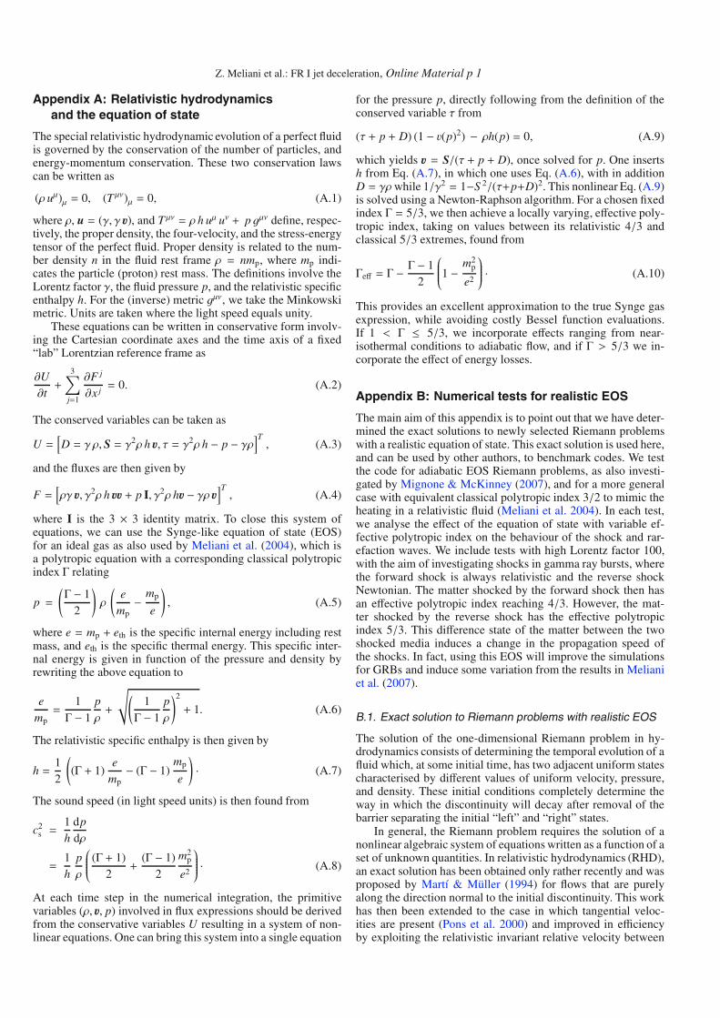
Z. Meliani et al.: FR I jet deceleration, Online Material p 1
Appendix A: Relativistic hydrodynamicsand the equation of state
The special relativistic hydrodynamic evolution of a perfect fluidis governed by the conservation of the number of particles, andenergy-momentum conservation. These two conservation lawscan be written as
(ρ uμ)μ = 0, (T μν)μ = 0, (A.1)
where ρ, u = (γ, γ u), and T μν = ρ h uμ uν + p gμν define, respec-tively, the proper density, the four-velocity, and the stress-energytensor of the perfect fluid. Proper density is related to the num-ber density n in the fluid rest frame ρ = nmp, where mp indi-cates the particle (proton) rest mass. The definitions involve theLorentz factor γ, the fluid pressure p, and the relativistic specificenthalpy h. For the (inverse) metric gμν, we take the Minkowskimetric. Units are taken where the light speed equals unity.
These equations can be written in conservative form involv-ing the Cartesian coordinate axes and the time axis of a fixed“lab” Lorentzian reference frame as
∂U∂t+
3∑j=1
∂F j
∂x j= 0. (A.2)
The conserved variables can be taken as
U =[D = γ ρ, S = γ2ρ h u, τ = γ2ρ h − p − γρ
]T, (A.3)
and the fluxes are then given by
F =[ργ u, γ2ρ h uu + p I, γ2ρ hu − γρ u
]T, (A.4)
where I is the 3 × 3 identity matrix. To close this system ofequations, we can use the Synge-like equation of state (EOS)for an ideal gas as also used by Meliani et al. (2004), which isa polytropic equation with a corresponding classical polytropicindex Γ relating
p =
(Γ − 1
2
)ρ
(e
mp− mp
e
), (A.5)
where e = mp + eth is the specific internal energy including restmass, and eth is the specific thermal energy. This specific inter-nal energy is given in function of the pressure and density byrewriting the above equation to
emp=
1Γ − 1
pρ+
√(1Γ − 1
pρ
)2
+ 1. (A.6)
The relativistic specific enthalpy is then given by
h =12
((Γ + 1)
emp− (Γ − 1)
mp
e
)· (A.7)
The sound speed (in light speed units) is then found from
c2s =
1h
dpdρ
=1h
pρ
⎛⎜⎜⎜⎜⎜⎝ (Γ + 1)2+
(Γ − 1)2
m2p
e2
⎞⎟⎟⎟⎟⎟⎠ · (A.8)
At each time step in the numerical integration, the primitivevariables (ρ, u, p) involved in flux expressions should be derivedfrom the conservative variables U resulting in a system of non-linear equations. One can bring this system into a single equation
for the pressure p, directly following from the definition of theconserved variable τ from
(τ + p + D) (1 − v(p)2) − ρh(p) = 0, (A.9)
which yields u = S/(τ + p + D), once solved for p. One insertsh from Eq. (A.7), in which one uses Eq. (A.6), with in additionD = γρwhile 1/γ2 = 1−S 2/(τ+p+D)2. This nonlinear Eq. (A.9)is solved using a Newton-Raphson algorithm. For a chosen fixedindex Γ = 5/3, we then achieve a locally varying, effective poly-tropic index, taking on values between its relativistic 4/3 andclassical 5/3 extremes, found from
Γeff = Γ − Γ − 12
⎛⎜⎜⎜⎜⎜⎝1 − m2p
e2
⎞⎟⎟⎟⎟⎟⎠ · (A.10)
This provides an excellent approximation to the true Synge gasexpression, while avoiding costly Bessel function evaluations.If 1 < Γ ≤ 5/3, we incorporate effects ranging from near-isothermal conditions to adiabatic flow, and if Γ > 5/3 we in-corporate the effect of energy losses.
Appendix B: Numerical tests for realistic EOS
The main aim of this appendix is to point out that we have deter-mined the exact solutions to newly selected Riemann problemswith a realistic equation of state. This exact solution is used here,and can be used by other authors, to benchmark codes. We testthe code for adiabatic EOS Riemann problems, as also investi-gated by Mignone & McKinney (2007), and for a more generalcase with equivalent classical polytropic index 3/2 to mimic theheating in a relativistic fluid (Meliani et al. 2004). In each test,we analyse the effect of the equation of state with variable ef-fective polytropic index on the behaviour of the shock and rar-efaction waves. We include tests with high Lorentz factor 100,with the aim of investigating shocks in gamma ray bursts, wherethe forward shock is always relativistic and the reverse shockNewtonian. The matter shocked by the forward shock then hasan effective polytropic index reaching 4/3. However, the mat-ter shocked by the reverse shock has the effective polytropicindex 5/3. This difference state of the matter between the twoshocked media induces a change in the propagation speed ofthe shocks. In fact, using this EOS will improve the simulationsfor GRBs and induce some variation from the results in Melianiet al. (2007).
B.1. Exact solution to Riemann problems with realistic EOS
The solution of the one-dimensional Riemann problem in hy-drodynamics consists of determining the temporal evolution of afluid which, at some initial time, has two adjacent uniform statescharacterised by different values of uniform velocity, pressure,and density. These initial conditions completely determine theway in which the discontinuity will decay after removal of thebarrier separating the initial “left” and “right” states.
In general, the Riemann problem requires the solution of anonlinear algebraic system of equations written as a function of aset of unknown quantities. In relativistic hydrodynamics (RHD),an exact solution has been obtained only rather recently and wasproposed by Martí & Müller (1994) for flows that are purelyalong the direction normal to the initial discontinuity. This workhas then been extended to the case in which tangential veloc-ities are present (Pons et al. 2000) and improved in efficiencyby exploiting the relativistic invariant relative velocity between
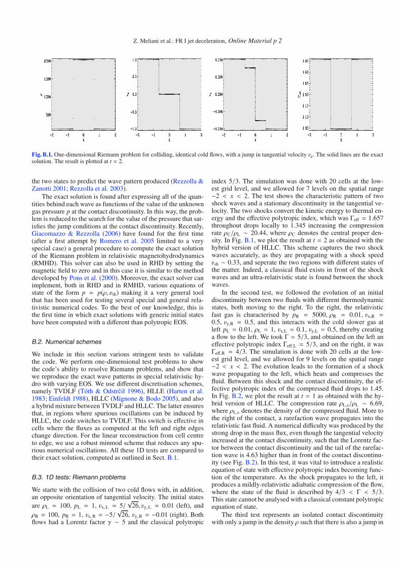
Z. Meliani et al.: FR I jet deceleration, Online Material p 2
Fig. B.1. One-dimensional Riemann problem for colliding, identical cold flows, with a jump in tangential velocity vy. The solid lines are the exactsolution. The result is plotted at t = 2.
the two states to predict the wave pattern produced (Rezzolla &Zanotti 2001; Rezzolla et al. 2003).
The exact solution is found after expressing all of the quan-tities behind each wave as functions of the value of the unknowngas pressure p at the contact discontinuity. In this way, the prob-lem is reduced to the search for the value of the pressure that sat-isfies the jump conditions at the contact discontinuity. Recently,Giacomazzo & Rezzolla (2006) have found for the first time(after a first attempt by Romero et al. 2005 limited to a veryspecial case) a general procedure to compute the exact solutionof the Riemann problem in relativistic magnetohydrodynamics(RMHD). This solver can also be used in RHD by setting themagnetic field to zero and in this case it is similar to the methoddeveloped by Pons et al. (2000). Moreover, the exact solver canimplement, both in RHD and in RMHD, various equations ofstate of the form p = p(ρ, eth) making it a very general toolthat has been used for testing several special and general rela-tivistic numerical codes. To the best of our knowledge, this isthe first time in which exact solutions with generic initial stateshave been computed with a different than polytropic EOS.
B.2. Numerical schemes
We include in this section various stringent tests to validatethe code. We perform one-dimensional test problems to showthe code’s ability to resolve Riemann problems, and show thatwe reproduce the exact wave patterns in special relativistic hy-dro with varying EOS. We use different discretisation schemes,namely TVDLF (Tóth & Odstrcil 1996), HLLE (Harten et al.1983; Einfeldt 1988), HLLC (Mignone & Bodo 2005), and alsoa hybrid mixture between TVDLF and HLLC. The latter ensuresthat, in regions where spurious oscillations can be induced byHLLC, the code switches to TVDLF. This switch is effective incells where the fluxes as computed at the left and right edgeschange direction. For the linear reconstruction from cell centreto edge, we use a robust minmod scheme that reduces any spu-rious numerical oscillations. All these 1D tests are compared totheir exact solution, computed as outlined in Sect. B.1.
B.3. 1D tests: Riemann problems
We starte with the collision of two cold flows with, in addition,an opposite orientation of tangential velocity. The initial statesare ρL = 100, pL = 1, vx,L = 5/
√26, vy,L = 0.01 (left), and
ρR = 100, pR = 1, vx,R = −5/√
26, vy,R = −0.01 (right). Bothflows had a Lorentz factor γ ∼ 5 and the classical polytropic
index 5/3. The simulation was done with 20 cells at the low-est grid level, and we allowed for 7 levels on the spatial range−2 < x < 2. The test shows the characteristic pattern of twoshock waves and a stationary discontinuity in the tangential ve-locity. The two shocks convert the kinetic energy to thermal en-ergy and the effective polytropic index, which was Γeff = 1.657throughout drops locally to 1.345 increasing the compressionrate ρC/ρL ∼ 20.44, where ρC denotes the central proper den-sity. In Fig. B.1, we plot the result at t = 2 as obtained with thehybrid version of HLLC. This scheme captures the two shockwaves accurately, as they are propagating with a shock speedvsh ∼ 0.33, and seperate the two regions with different states ofthe matter. Indeed, a classical fluid exists in front of the shockwaves and an ultra-relativistic state is found between the shockwaves.
In the second test, we followed the evolution of an initialdiscontinuity between two fluids with different thermodynamicstates, both moving to the right. To the right, the relativisticfast gas is characterised by pR = 5000, ρR = 0.01, vx,R =0.5, vy,R = 0.5, and this interacts with the cold slower gas atleft pL = 0.01, ρL = 1, vx,L = 0.1, vy,L = 0.5, thereby creatinga flow to the left. We took Γ = 5/3, and obtained on the left aneffective polytropic index Γeff,L = 5/3, and on the right, it wasΓeff,R = 4/3. The simulation is done with 20 cells at the low-est grid level, and we allowed for 9 levels on the spatial range−2 < x < 2. The evolution leads to the formation of a shockwave propagating to the left, which heats and compresses thefluid. Between this shock and the contact discontinuity, the ef-fective polytropic index of the compressed fluid drops to 1.45.In Fig. B.2, we plot the result at t = 1 as obtained with the hy-brid version of HLLC. The compression rate ρL,s/ρL ∼ 6.69,where ρL,s denotes the density of the compressed fluid. More tothe right of the contact, a rarefaction wave propagates into therelativistic fast fluid. A numerical difficulty was produced by thestrong drop in the mass flux, even though the tangential velocityincreased at the contact discontinuity, such that the Lorentz fac-tor between the contact discontinuity and the tail of the rarefac-tion wave is 4.63 higher than in front of the contact discontinu-ity (see Fig. B.2). In this test, it was vital to introduce a realisticequation of state with effective polytropic index becoming func-tion of the temperature. As the shock propagates to the left, itproduces a mildly-relativistic adiabatic compression of the flow,where the state of the fluid is described by 4/3 < Γ < 5/3.This state cannot be analysed with a classical constant polytropicequation of state.
The third test represents an isolated contact discontinuitywith only a jump in the density ρ such that there is also a jump in
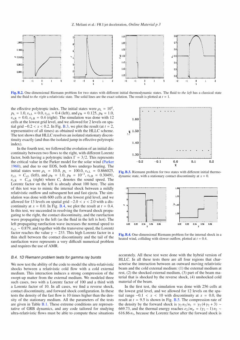
Z. Meliani et al.: FR I jet deceleration, Online Material p 3
Fig. B.2. One-dimensional Riemann problem for two states with different initial thermodynamic states. The fluid to the left has a classical stateand the fluid to the right a relativistic state. The solid lines are the exact solution. The result is plotted at t = 1.
the effective polytropic index. The initial states were ρL = 104,pL = 1.0, vx,L = 0.0, vy,L = 0.4 (left), and ρR = 0.125, pR = 1.0,vx,R = 0.0, vy,R = 0.4 (right). The simulation was done with 12cells at the lowest grid level, and we allowed for 2 levels on spa-tial grid −0.2 < x < 0.2. In Fig. B.3, we plot the result (at t = 2,representative of all times) as obtained with the HLLC scheme.The test shows that HLLC resolves an isolated stationary discon-tinuity exactly (and thus the isolated jump in effective polytropicindex).
In the fourth test, we followed the evolution of an initial dis-continuity between two flows to the right, with different Lorentzfactor, both having a polytropic index Γ = 3/2. This representsthe critical value in the Parker model for the solar wind (Parker1960), and due to our EOS, both flows undergo heating. Theinitial states were ρL = 10.0, pL = 100.0, vx,L = 0.866025,vy,L = Cs,L (left), and ρR = 1.0, pR = 10−3, vx,R = 0.30491,vy,R = Cs,R (right) where Cs denotes the sound speed. TheLorentz factor on the left is already about 100 here. The aimof this test was to mimic the internal shock between a mildlyrelativistic outflow and subsequent hot and fast ejecta. The sim-ulation was done with 600 cells at the lowest grid level, and weallowed for 13 levels on spatial grid −2.0 < x < 2.0 with a dis-continuity at x = 0.0. In Fig. B.4, we plot the result at t = 0.4.In this test, we succeeded in resolving the forward shock propa-gating to the right, the contact discontinuity, and the rarefactionwave propagating to the left (as the fluid in the left is hot). Theleft propagating rarefaction wave increases the normal speed tovx,L ∼ 0.879, and together with the transverse speed, the Lorentzfactor reaches the value γ ∼ 233. This high Lorentz factor in athin shell between the contact discontinuity and the tail of therarefaction wave represents a very difficult numerical problemand requires the use of AMR.
B.4. 1D Riemann problem tests for gamma ray bursts
We now test the ability of the code to model the ultra-relativisticshocks between a relativistic cold flow with a cold externalmedium. This interaction induces a strong compression of theswept-up matter from the external medium. We modeled threesuch cases, two with a Lorentz factor of 100 and a third witha Lorentz factor of 10. In all cases, we find a reverse shock,contact discontinuity, and forward shock configuration. In thesetests the density of the fast flow is 10 times higher than the den-sity of the stationary medium. All the parameters of the testsare given in Table B.1. These extreme conditions are represen-tative of GRB dynamics, and any code tailored for studyingultra-relativistic flows must be able to compute these situations
Fig. B.3. Riemann problem for two states with different initial thermo-dynamic state, with a stationary contact discontinuity at x = 0.
Fig. B.4. One-dimensional Riemann problem for the internal shock in aheated wind, colliding with slower outflow, plotted at t = 0.4.
accurately. All these test were done with the hybrid version ofHLLC. In all these tests there are all four regions that char-acterise the interaction between an outward moving relativisticbeam and the cold external medium: (1) the external medium atrest, (2) the shocked external medium, (3) part of the beam ma-terial that is shocked by the reverse shock, (4) unshocked coldmaterial of the beam.
In the first test, the simulation was done with 256 cells atthe lowest grid level, and we allowed for 12 levels on the spa-tial range −0.1 < x < 10 with discontinuity at x = 0.0, theresult at t = 9.5 is shown in Fig. B.5. The compression rate ofthe density by the forward shock is γ2 n2/n1 = γ2 (4 γ2 + 3) ∼669.73, and the thermal energy reaches e2/mp = (γ2 − 1) n2 ∼616.86 n1, because the Lorentz factor after the forward shock is

Z. Meliani et al.: FR I jet deceleration, Online Material p 4
Fig. B.5. GRB test case: a cold Lorentz factor 100 flow penetrates the cold static medium. The solid lines are the exact solution. Left: the density,centre: Lorentz factor, right: effective polytropic index.
Fig. B.6. Second test case: a cold Lorentz factor 10 flow penetrates into cold static medium. The solid lines are the exact solution. Left: the density,center: Lorentz factor, right: effective polytropic index.
Table B.1. GRB test parameters, the Lorentz factor and the transversespeed of left flow, and the density ratio between left and right state. Thefluid in the right is initially at rest.
Test γL ρL/ρR vy,L1 100 10 0.02 10 10 0.03 100 10 0.01
γ2 =γ1/2
4 f 1/4
√2∼ 12.57 where f = n4
n1= 10 (Sari & Piran 1995).
In the region of the shocked swept-up matter, the polytropic in-dex is 4/3 as the thermal energy is higher than the mass en-ergy. Moreover, the reverse shock is propagating with a relative
Lorentz factor γ3 ∼√
γ4
2 f 1/2 ∼ 3.97, so that the matter is com-
pressed according to n3/n4 ∼ (4 γ3 + 3) ∼ 18.9 (the exact ob-tained value is in fact somewhat lower) and the thermal energyenhanced e3/mp = (γ3 − 1) n3 = 56.07 n4. This implies that thestate of the matter is also relativistic and the polytropic indexΓ3 ∼ 4/3. In this case both the forward shock and the reverseshock are relativistic. The numerical difficulty is to resolve thevery thin region resulting from the strong compression of swept-up matter, which has an extent of ΔX2(t) = 0.0015t. It is easierto resolve the region between the reverse shock and the contactdiscontinuity, as the compression by the reverse shock is weaker,and this region extends over ΔX3(t) = 0.00315t.
In a second test, a relativistic cold flow with a Lorentz fac-tor 10 interacts with a cold external medium. This case corre-sponds more to the interaction of a jet in AGN or micro-quasarwith external medium than to GRB case. The simulation was
done with 256 cells at the lowest grid level, and we allowed for8 levels, the result at t = 9.5 is shown in Fig. B.6. With theweak efficiency of the forward shock γ2 ∼ 3.79 to compressthe external medium, the thermal energy of swept-up matter in-creases less and the effective polytropic index reaches a value ofΓeff = 1.356. The compression rate in this case is lower, hencethe swept-up matter has an extent of ΔX2(t) = 0.0163t, which al-lows the contact discontinuity and the forward shock to be easilyresolved. The reverse shock is mildly relativistic with a relativeLorentz factor γ3 ∼ 1.53 such that the effective polytropic in-dex of the shocked beam only drops to Γeff = 1.48. This makesthe reverse shock less efficient at compressing the beam matter(compared to the case of a shock with a lower polytropic indexΓ = 4/3), and the region between the reverse shock and contactdiscontinuity then extends over ΔX3(t) = 0.0225t.
When we compare these two simulations, which differ in theLorentz factor of the beam, namely 100 versus 10, these testsshow the dual numerical difficulty when the Lorentz factor in-creases: (1) the compression rate enhances and (2) the distancebetween the forward shock and contact discontinuity and be-tween the reverse shock and contact discontinuity decreases.
The last test is a variant of the first, with the Lorentz factor ofthe beam 100 and transverse velocity v4,y = 0.01. Introducing atransverse velocity in the beam increases the numerical difficultyof resolving the contact discontinuity with a jump in both den-sity and transverse speed. The simulation is done with 256 cellsat the lowest grid level, and we allow for 12 levels on the spa-tial range −0.1 < x < 10, the result at t = 9.5 is shown inFig. B.7. As a result of the interaction, the transverse velocityin the beam material shocked by the reverse shock increases to
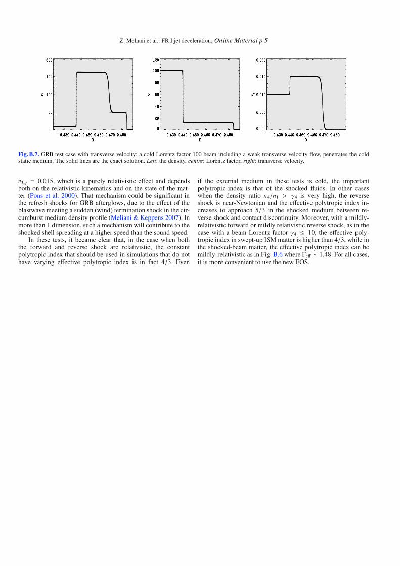
Z. Meliani et al.: FR I jet deceleration, Online Material p 5
Fig. B.7. GRB test case with transverse velocity: a cold Lorentz factor 100 beam including a weak transverse velocity flow, penetrates the coldstatic medium. The solid lines are the exact solution. Left: the density, centre: Lorentz factor, right: transverse velocity.
v3,y = 0.015, which is a purely relativistic effect and dependsboth on the relativistic kinematics and on the state of the mat-ter (Pons et al. 2000). That mechanism could be significant inthe refresh shocks for GRB afterglows, due to the effect of theblastwave meeting a sudden (wind) termination shock in the cir-cumburst medium density profile (Meliani & Keppens 2007). Inmore than 1 dimension, such a mechanism will contribute to theshocked shell spreading at a higher speed than the sound speed.
In these tests, it became clear that, in the case when boththe forward and reverse shock are relativistic, the constantpolytropic index that should be used in simulations that do nothave varying effective polytropic index is in fact 4/3. Even
if the external medium in these tests is cold, the importantpolytropic index is that of the shocked fluids. In other caseswhen the density ratio n4/n1 > γ4 is very high, the reverseshock is near-Newtonian and the effective polytropic index in-creases to approach 5/3 in the shocked medium between re-verse shock and contact discontinuity. Moreover, with a mildly-relativistic forward or mildly relativistic reverse shock, as in thecase with a beam Lorentz factor γ4 ≤ 10, the effective poly-tropic index in swept-up ISM matter is higher than 4/3, while inthe shocked-beam matter, the effective polytropic index can bemildly-relativistic as in Fig. B.6 where Γeff ∼ 1.48. For all cases,it is more convenient to use the new EOS.


![Detection of Discontinuities [GMAW]](https://static.fdocuments.us/doc/165x107/577cd9031a28ab9e78a27ba6/detection-of-discontinuities-gmaw.jpg)