Faculty of Civil and Industrial Engineering - uniroma1.it · Faculty of Civil and Industrial...
117
Faculty of Civil and Industrial Engineering Thesis of Master Degree in TRANSPORT SYSTEMS ENGINEERING European Rail Traffic Management System Level 1 plus Radio Infill Unit capacity performance Supervisor | Prof. Stefano Ricci Company tutor | Eng. Federico Rossi Candidate | Vahid Ranjbar Academic year 2016/2017
-
Upload
trankhuong -
Category
Documents
-
view
236 -
download
1
Transcript of Faculty of Civil and Industrial Engineering - uniroma1.it · Faculty of Civil and Industrial...

Faculty of Civil and Industrial Engineering
Thesis of Master Degree in
TRANSPORT SYSTEMS ENGINEERING
European Rail Traffic Management System Level 1 plus Radio Infill Unit capacity performance
Supervisor | Prof. Stefano Ricci
Company tutor | Eng. Federico Rossi
Candidate | Vahid Ranjbar
Academic year 2016/2017


This thesis is dedicated to my Parents and my family
For their endless love, support and encouragement.


Acknowledgement
I would like to express my sincere gratitude to people whom without their support and help this
thesis was not possible.
I would like to express my sincere gratitude to my supervisor Prof. Stefano Ricci for the
continuous support of my master study and research, for his patience, motivation, enthusiasm,
and immense knowledge. His guidance helped me in all the time of research and writing of this
thesis.
I would like to thank my compony tutor Eng. Federico Rossi for offering me the internship
opportunities in Bombardier Transportation Italy and leading me working on this exciting project.
I would like to thank the Radio Infill team and lab mates, Romano Bacci, Arianna Totonelli, Luca
Di Tommaso, Jonni Ciribe, Filippo Di pace, Michele Pappalardo for support, help and sharing their
knowledge, I greatly look forward to having all of you as colleagues in near future.
I want to thank my family, my mother and my brother Javad for their support, encouragement
and their endless love.
I would like to thank all professors who have guided me in my master study and their professional
suggestions specially professor Malavasi, prof. Fusco, prof. Di Mascio.
I would like to thank my close friends who have encouraged me during these years.


Contents
Summary ......................................................................................................................................... 1
Chapter 1 ......................................................................................................................................... 2
1 The European railway system .................................................................................................. 2
1.1 The Railway interoperability ............................................................................................ 2
1.1.1 Technical specification for interoperability (TSI) ...................................................... 4
1.2 European Railway Traffic Management System (ERTMS) ................................................... 4
1.2.1 European Train Control System (ETCS) ......................................................................... 4
1.2.2 Technical and functional specification ......................................................................... 5
1.2.3 Architecture and subsystems ....................................................................................... 5
1.2.4 Application levels .......................................................................................................... 9
1.2.5 Running level transition .............................................................................................. 19
1.2.6 Operating modes ........................................................................................................ 22
1.2.7 Message language ...................................................................................................... 32
1.3 System for Mobile Communications – Railway (GSM-R) .................................................. 34
1.3.1 History and reference standards ................................................................................ 35
1.3.2 Network requirements ............................................................................................... 36
1.3.3 Mobile equipment core specification ......................................................................... 41
1.3.4 Network configuration ................................................................................................ 42
1.4 European Traffic Management Layer (ETML) ................................................................ 42
Chapter 2 ....................................................................................................................................... 43
2 Radio Infill Unit description and requirements ..................................................................... 43
2.1 Principles ........................................................................................................................ 43
2.2 Integrity of data consistency ............................................................................................. 44
2.3 Interfaces ........................................................................................................................... 44
2.3.1 External interface group ............................................................................................. 45
2.3.2 Internal Interfaces ...................................................................................................... 45
2.3.3 Test Interfaces ............................................................................................................ 45
2.4 EURORADIO protocol ..................................................................................................... 47

2.4.1 EURORADIO General Architecture.............................................................................. 47
2.4.2 EURORADIO level and interfaces ................................................................................ 47
2.5 Software architecture .................................................................................................... 48
2.5.1 The Safety layers ..................................................................................................... 48
2.5.2 The Transport Layer .................................................................................................... 49
2.6 Functionality and system requirements ........................................................................ 49
2.7 Infill movement authority (MA) ..................................................................................... 51
2.7.1 Movement Authority update ...................................................................................... 52
2.7.1.1 Movement Authority Extension with infill information ......................................... 53
2.7.1.2 Movement Authority shortening ............................................................................. 54
2.7.1.3 Movement Authority Repetition ............................................................................. 54
Chapter 3 ....................................................................................................................................... 56
3 Radio Infill Unit Bombardier .................................................................................................. 56
3.1 System Overview ............................................................................................................ 57
3.1.1 Radio Infill Unit System Environment ......................................................................... 58
3.2 Radio Infill Unit System Functionality Overview ............................................................ 58
3.2.1 Signal Manager RIU (SMR) ...................................................................................... 60
3.2.2 Radio Infill Unit Processing Unit ............................................................................. 61
3.2.3 Radio Infill Unit System Platform ............................................................................ 61
3.3 Radio Infill Unit Functional Structure ............................................................................. 63
3.4 Description of the system .............................................................................................. 65
3.4.1 Network connections .............................................................................................. 65
3.4.2 Telecommunication ................................................................................................ 67
3.5 Communication Protocol ............................................................................................... 67
3.5.1 Configuration Data .................................................................................................. 69
3.5.2 Normal execution flow............................................................................................ 71
Chapter 4 ....................................................................................................................................... 72
4 Test environment .................................................................................................................. 72
4.1 Main target ..................................................................................................................... 72
4.2 Architecture of the test environment ............................................................................... 72
4.3 Test environment description ........................................................................................... 75

4.4 Interfaces ........................................................................................................................... 82
4.5 Configuration process........................................................................................................ 82
4.6 Realization of Base Project ................................................................................................ 83
4.6.1 Test case Configuration: ......................................................................................... 83
4.6.2 Data collection ........................................................................................................ 84
4.7 Architecture of test environment ..................................................................................... 84
Chapter 5 ....................................................................................................................................... 89
5 The line capacity evaluation .................................................................................................. 89
5.1 Purpose........................................................................................................................... 89
5.1.1 ETCS in interoperable corridors .............................................................................. 89
5.2 The study case description .................................................................................................. 90
5.3 The study Methodology ...................................................................................................... 90
5.4 Calculation of capacity consumption ............................................................................. 94
5.4.1 Occupancy time ...................................................................................................... 94
5.4.2 Additional time ....................................................................................................... 94
5.4.3 Defined time period ................................................................................................ 95
5.4.4 Capacity consumption ............................................................................................ 95
5.5 The Scenarios ................................................................................................................. 96
5.5.1 Scenario 0 ................................................................................................................ 96
5.5.2 Scenario 1 ................................................................................................................ 98
5.5.3 Scenario 2 .............................................................................................................. 100
Conclusions ................................................................................................................................. 102
References .................................................................................................................................. 104
Acronyms and Abbreviations ...................................................................................................... 106


1
Summary
In this thesis, which was realized at Bombardier Italy, after a careful analysis of the functional and system requirements of the Radio Infill Unit (the system that provides a continuous communication between wayside equipment and the train via Radio to have information’s in advance about the state of the railroad), as main aim of the present thesis is studied effect of application of RIU on capacity performance of the line. Bombardier Italy is implemented a simulator that provides the possibility of running tests and operative scenarios for verification and analysis of the functionality of the system ERTMS/ETCS L1 + Radio infill Unit. In Chapter 1, after a brief overview on the European regulatory environment in railways, is described the European Railway Traffic Management System (ERTMS), the European Train Control System (ETCS) and the radio-based telecommunications standard used (GSM-R). Chapter 2 describes principles, functionality and system requirements of Radio Infill Unit (RIU), in accordance with the specifications provided by European Railway Agency (ERA) and are provided some scenarios for running tests and typical applications that describe the key benefits and advantages of using the Radio Infill Unit in the railway network. In Chapter 3, it is described the hardware architecture and the communication protocol developed by Bombardier Italy. In chapter 4, it is described the test environment developed by Bombardier Italy for simulation of train running, analyses of functionality of RIU and interaction of wayside equipment with onboard subsystem. In chapter 5, to verify the effects of the implementation of ERTMS L 1 + Radio Infill unit on of the line capacity, it was evaluated and compared the capacity of line in current situation equipped by SCMT, versus upgraded situation to ERTMS L 1 + RIU with the corresponding proportional speed increasing in different scenarios.

2
Chapter 1
1 The European railway system
In this chapter, after a brief overview on the European regulatory environment in the railway sector and on the principle of interoperability, it is described the European Railway Traffic Management System (ERTMS) and the European Train Control System (ETCS) and the standard of telecommunications radio used (GSM-R).
1.1 The Railway interoperability
The creation of an integrated European railway area calls “interoperability” or technical compatibility of infrastructure, energy, rolling stock, telematics applications, and traffic operation and management subsystems, including drafting recommendations to the European Commission for update and revision of the Technical Specifications for Interoperability (TSI) and publication of national rules. Over the years, national rail networks have developed different technical specifications for infrastructure, different gauge widths, electrification standards and safety and signaling systems making difficult and expensive to run a train from one country to another. Specific EU legislation exists to promote interoperability and overcome such differences. The European Railway Agency plays a central role in promoting interoperability and harmonizing technical standards, a process in which cooperation between EU Member States and rail stakeholders is essential. In accordance with Art. 7 of Decision 2006/860/EC and Art. 3 of Decision 2006/679 /EC relating to the Interoperability Technical Specifications for the Command Control Subsystem and Signaling of the Trans-European High-Speed and Conventional Network respectively, each State Member must define a national plan for the implementation of the interoperable ERTMS system, including its subsystems: ETCS, the European Train Control System, and GSM-R, a radio communication system for voice and data derived from GSM. Description of the Migration Strategy for the interoperable system of the high speed and conventional network is defined by the Directives 96/48 / EC and 2001/16 / EC and subsequent Decisions. The Interoperability Unit is divided into four sectors:
• Rolling Stock, responsible for all the issues related to the vehicles, including drafting and revising technical specifications for interoperability;
• Fixed Installations, responsible for all the issues related to the energy and infrastructure subsystems, including drafting and revising technical specifications for interoperability;
• Operational, responsible for drafting and revising the TSIs on telematics applications and on operation and traffic management;
• Conformity Assessment, Registers and Standards, responsible for the conformity assessment, setting up and maintaining interoperability registers, collaboration with
3
European standardization organizations and OTIF (Intergovernmental Organization for International Carriage by Rail) and for monitoring railway interoperability.
The main tasks of the Interoperability Unit sectors are:
• Managing the issues related to infrastructure, energy, rolling stock, telematics
application, traffic operation and management subsystems, including drafting
recommendations to the European Commission for update and revision of the Technical
Specifications for Interoperability (TSIs) and publication of applicable national rules;
• Collaboration with international organizations (OTIF Intergovernmental Organization for International Carriage by Rail, OSJD Organization for Co-operation between Railways);
• Coordination of TSI-related activities with the European Standardization Bodies (CEN/CENELEC, ETSI), the Notified Bodies (NB-Rail) and National Safety Authorities (NSA);
• Setting up and maintenance of infrastructure and vehicle related registers which support railway interoperability through transparency;
• Activities related to vocational competences on common uniform criteria and the assessment of staff involved in the operation and the maintenance.
In this case, refer the directives 2016/797 of the European parliament and of the council of 11th May 2016 on the interoperability of the rail system within the European Union (Recast), which lists the conditions to be met to achieve interoperability within Community territory of interoperable European conventional rail system and high speed, with the following objectives.
General objectives The general objective is to achieve interoperability within the European Union's rail system by meeting the provisions set out in Directive (EU) 2016/797 [1] on the interoperability of the rail system within the European Union (Recast), notably those of the Technical Specifications for Infrastructure (TSI) concerning Telematics Applications for Passengers (TAP) and Telematics Applications for Freight (TAF). Thereby, for the railway lines forming part of the TEN-T, compliance with the infrastructure requirements set out in the TEN-T (Trans-European Networks – Transport), Guidelines shall be ensured. The railway regulatory framework at Union and Member State level should set clear roles and responsibilities for ensuring compliance with the safety, health and consumer protection rules applying to the railway networks. This Directive should not lead to a reduced level of safety or increase costs in the Union rail system. To that end, the European Union Agency for Railways (“the Agency”) established by Regulation (EU) 2016/796 [1] of the European Parliament and of the Council and the national safety authorities should take full responsibility for the authorizations they issue. Specific objectives Interoperability shall be promoted via the following specific objectives:
• Ensuring easy access for users to information about itinerary, time and availability,
including consultation and dissemination activities for the promotion of TAP and TAF;

4
• Ensuring compliance of the rail system and its subsystems with the TSI, notably on
infrastructure, energy, rolling stock for passengers and freight transport, operation,
telematics applications, control command and signaling, safety in railway tunnels;
• Simplifying procedures for the authorization, placing in service and use of rolling stock on
the Union's railway network;
• Ensuring compliance with other relevant requirements of the TEN-T Guidelines;
• Ensuring the establishment of Rail Freight Corridors, their full extension to and integrated
development with the core network corridors (e.g. through studies, the support of
managerial structures and other relevant action), in particular the development of
terminals and their access from/to the rail network and coordination of rail traffic
management and terminal operations as well as the provision of dedicated capacity for
international freight trains (prearranged train paths and reserve capacity)
1.1.1 Technical specification for interoperability (TSI)
Technical specifications for interoperability (TSI) means the specifications by which each subsystem or part of subsystem is covered, to meet the essential requirements and to ensure the interoperability of the European Community high speed and conventional rail systems. The European railway agency (ERA) performs the revision of existing TSI, keeps them up to date, and supports the sector in their application by issuing application guides and by dissemination and training actions. When necessary, the Agency may also draft new TSI, based on emanate from the Commission.
1.2 European Railway Traffic Management System (ERTMS)
The European Railway Traffic Management System (ERTMS) is a major industrial project being implemented to enhance cross-border interoperability through Europe by creating a single standard for railway signaling. ERTMS is the European Rail Traffic Management System, which intends to remove the technical barriers against the interoperability regarding the train control and command system. ERTMS contains three basic elements:
• ETCS, European Train Control System;
• GSM-R, Global System for Mobile Communications for Railway;
• ETML, European Traffic Management Layer;
1.2.1 European Train Control System (ETCS)
ETCS is, in fact, an Automatic Train Protection (ATP) system developed and performed by
European Commission and it is based on cab signaling and intermittent and/or continuous track
to train data transmission. It provides an inherently safe operational environment for the
5
movement of trains throughout the network, while facilitating a greater network carrying
capacity. The system aims to standardize the signaling and train control systems and remove the
hindrance to the development of international rail traffic. It specifies for compliance with the
High Speed and Conventional Interoperability Directives.
The need for ETCS stems from European Union (EU) Directive 96/48/CE [2] about the
interoperability of high-speed trains, followed by Directive 2001/16/CE [3] extending the concept
of interoperability to the conventional rail system. ETCS specifications have become part of, or
are referred to, the technical specification for interoperability for railway control-command
systems, which is a piece of European legislation managed by the European Railway Agency. It is
a legal requirement that all new, upgraded or renewed tracks and rolling stock in the European
railway system should adopt ETCS, possibly keeping legacy systems for backward compatibility.
Many networks outside the EU have also adopted ETCS, generally for high-speed rail projects.
1.2.2 Technical and functional specification
ETCS is based on a coherent and comprehensive set of technical specifications and functional, drafted, developed and updated by UNISIG, an industrial consortium created to develop the ERTMS/ETCS technical specifications. These specifications ensure interoperability required by the European directives and allow different vendors to provide system components compatible with each other. Technical specifications treat the functions, procedures and performance, as well as the architecture of the ETCS system and the interfaces between various subsystems. Thanks to a highly modular structure, the various parts the system can be developed or updated separately, even from different suppliers, and then integrated with facility. Among the main functions, ETCS includes:
• Operational: start-up and testing of the instruments on board; entering specific data of the train and the driver; operations of maneuver; isolation of the on-board instrumentation; compatibility with the control systems and national control;
• Infrastructure: collection of location data and line conditions; movement authority;
• Onboard computer: calculation of speed profiles; location of train; calculation and supervision of the current speed; supervision of compliance with the signals by the driver;
• Safety features: emergency stop of the train; run on sight.
1.2.3 Architecture and subsystems
The control and command signaling element of ERTMS, due to the nature of the required
functions, is divided into two subsystems:
1. Trackside;
2. On-board;
6
Supporting equipment is also required to form a complete signaling system and, in some applications, to transfer data between the ERTMS trackside equipment, the ERTMS onboard equipment and other systems. The environment of ERTMS/ETCS is composed of:
a) The train, which will be considered in the train interface specification; b) The driver, which will be considered via the driver interface specification; c) Other onboard interfaces; d) External trackside systems (interlocking, control centers, etc.), for which no
interoperability requirement will be established.
1. Trackside subsystem
• Depending of the application levels [4], the trackside sub-system can be composed of:
• Eurobalise;
• Lineside electronic unit;
• Radio communication network (GSM-R);
• Radio Block Centre (RBC);
• Euroloop;
• Radio Infill Unit;
• Key Management Centre (KMC); Eurobalise The Eurobalise Transmission System is a safe spot transmission based system conveying safety related information between the wayside infrastructure and the train and vice versa. The Eurobalise Transmission System is a spot transmission system, where transmission is implemented by Balises. Information can be transmitted both Up-link and Down-link. Information transmitted from an Up-link Balise to the On-board Transmission equipment is fixed or variable depending upon the application (Up-link data transmission). Information can be received by a Down-link Balise from the train (Down-link data transmission). The Balises can transmit, thanks to the coupling magnetic with an antenna located under the locomotive, specific telegrams to the subsystem board. During the inductive coupling, Eurobalise antenna emits at a frequency of 27 (095 MHz) an excitation signal (coded Frequency Shift Keying, FSK) to the Balises, which responds at a frequency of 4 (237 MHz). The information transmitted from track to train (Up-link) may include:
• Signaling data;
• Control data;
• Position and geographical information;
• Power collection information;
• Train target running information;
• Route;
• Permanent speed restrictions;
• Temporary speed restrictions;
• Fixed obstructions such as buffer stops;
• Movement authority;

7
• Gradients;
• Support to cable and radio in-fill functionality;
• Linking data;
• Other information. The information transmitted from train to track (Down-link) may include:
• Makeup of the train;
• Changes to train status that might affect the maximum safe speed;
• Track to train adhesion;
• Status of traction control;
• Other information between the tracks. Lineside electronic unit (LEU) The lineside electronic units are electronic devices, which generate telegrams to be sent by Balises, based on information received from external trackside systems. Radio communication network (GSM-R) The GSM-R radio communication network is used for the bi-directional exchange of messages between on-board sub-systems and RBC or radio infill units. Radio Block Centre (RBC) The Radio Block Centre is a wayside equipment based on radio communication that provides continuous contact with the train to keep it up to date about state of railroad and aspect of signals. The RBC provides movement authorities to have a safe movement of trains on the railway infrastructure area. To receive information from the RBC the train must be equipped with ERTMS L2/3 board. The security and the reliability of information exchanged by radio is guaranteed by Euroradio protocol. Euroloop Transmission system which allows to obtain updated continuous information along the railroad. The Euroloop are formed by a cracked coaxial cable that, disposed along the track for a specific extension, allows wayside subsystem to communicate the updated information for all the time that the train takes to follow it. The cable basically works by transmitting antenna and the data submitted they are picked up by the on-board subsystem via the antenna. Eurobalise and processed by the on-board subsystem. In this way, is the wayside equipment can transmit update information to train without necessity to wait for the next information point, with considerable advantages in terms of safety and performance of the line. As for Eurobalise, the communication interface with the luminous signaling systems along the tracks are built using LEU. Radio infill unit (RIU) Radio-based telecommunication system, by means of GSM-R, which allows to forward to the train, in advance, the corresponding message of the next signal in the direction of travel, without waiting for passing on the relevant information point. In this way, for example, a train is
8
approaching a signal at danger can cancel braking as soon as the signal gives ahead, without having to wait to arrive in correspondence of the signal itself. As for the RBC, the safety and communication reliability are entrusted to the Protocol Euro radio. KMC The role of the KMC is to manage the cryptographic keys, which are used to secure the EURORADIO communications between the ERTMS/ETCS entities (on-board equipment’s, RBCs and RIUs).
2. On-board sub-system The on-board core subsystem is represented by the onboard European Vital Computer (EVC), which is responsible for compilation and presentation of data acquired through interfaces with the GSM-R radio system, the signaling system side infrastructure and the equipment to board the train. The computer defined vital performs crucial functions for the safety of train. To this end, the hardware and software architecture EVC is strongly bound by requirements of safety and security to ensure maximum reliability in all circumstances. The interfaces and the available modules
a) ERTMS/ETCS on-board equipment; b) on-board part of the GSM-R radio system;
a) ERTMS/ETCS on-board equipment;
The ERTMS/ETCS onboard equipment is a computer based system that supervises movement of the train to which it belongs, based on information exchanged with the trackside subsystem. The interoperability requirements for the ERTMS/ETCS onboard equipment are related to the functionality and the data exchange between the trackside subsystems and the onboard subsystem. ERTMS/ETCS KERNEL The core of the onboard system, responsible for the processing of all significant data coming from the sensors and from the various signaling systems currently active and able to interface with main on-board equipment to ensure a correct running of the train by the driver. Human-Machine Interface (HMI) constitutes the interface between the driver and the on-board equipment, correct display of information and interface with the driver represent the key operational factor for this essential onboard equipment. Balise Transmission Module (BTM) Represent a system capable of powering, reading and interpreting the information subsequently transferred to the kernel, coming from the Eurobalise positioned along the track. Loop Transmission Module (LTM) It is an additional function of ERTMS/ETCS for improvement of line performance. Scope of Loop Transition Module is transmitting messages from transponders in correspondence with warning signals with respect to the information points. Specific Transmission Module(STM)
9
The onboard national train control systems, for example Automatic Train Protection (ATP), can be integrated with the ERTMS onboard equipment if implemented as a Specific Transmission Module (STM). Juridical Event Recorder(JER) Is an ERTMS onboard equipment providing an interface for the provision of juridical data related to ERTMS operation, including ERTMS DMI events such as warnings and alarms, and the use of the isolation switch, to an onboard data recorder. The juridical data can be used to support investigation into incidents and for routine system monitoring.
b) On-board part of the GSM-R radio system The Onboard radio communication system (GSM-R) is an interface for direct communication with the Radio Block Centre (RBC) or the Radio In-Fill Unit (RIU) via GSM-R and Euroradio protocol; in the following section, it is described the complete specification about onboard radio system.
1.2.4 Application levels
ETCS is organized into different main application layers, where successive levels are different from the previous ones, only for the implementation of additional features. In this way, we have obvious advantages in terms of costs and change management, since the transition from a lower level to higher level does not require replacement, but only the addition of new modules. Moreover, the backward compatibility is guaranteed, so that the equipped trains with higher application levels may still use on the lines, in which they are implemented at lower levels and vice versa. The different ERTMS/ETCS application levels are a way to express the possible operating relationships between track and train. Level definitions (Fig.1) are related to the trackside equipment, the way trackside information reaching the on-board units and to which functions are processed in the trackside and in the on-board equipment respectively. Different levels have been defined to allow each individual railway administration to select the appropriate ERTMS/ETCS application trackside, according to their strategies, to their trackside infrastructure and to the required performance. Furthermore, the different application levels permit the interfacing of individual signaling systems and train control systems to ERTMS/ETCS. National Train Control (NTC)
The NTC level is used to run ERTMS/ETCS equipped trains on lines equipped with National Train Control and speed supervision systems. Train control information generated trackside by the national train control system is transmitted to the train via the communication channels of the underlying national system.

10
Fig.1 ERTMS Application Levels
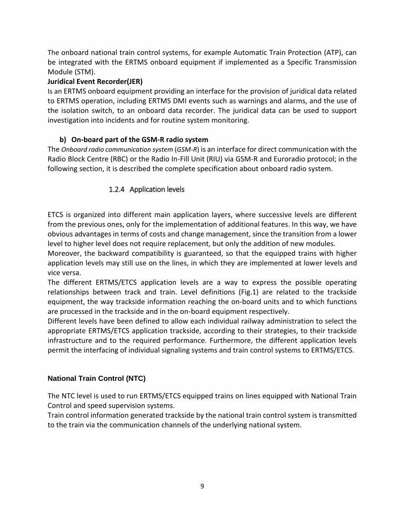
Lineside optical signals might be necessary or not, depending on the performance and functionality of the underlying systems. The achievable level of supervision is like the one provided by the underlying national systems. Train detection and train integrity supervision are performed by equipment external to ERTMS/ETCS. NTC Level uses no ERTMS/ETCS track-train information except to announce/command level transitions and specific commands related to Balise transmission, therefore, Eurobalise still must be read. The information displayed to the driver depends on the functionality of the underlying national system. The active national system is indicated to the driver as part of that information. Full train data should be entered in order not to have to stop a train at a level transition position and to supervise maximum train speed. A combination of national systems can be regarded as one NTC level. Depending on the functionality and the configuration of the specific national system installed onboard, the ERTMS/ETCS Onboard system may need to be interfaced to it, to perform the transitions from/to the national system and/or to give access to ERTMS/ETCS Onboard resources (e.g. DMI). This can be achieved through a device called an STM (Specific Transmission Module) using a standardized interface (Fig.2, Fig.3).

11
Fig.2 National Train Control Level
Level 0
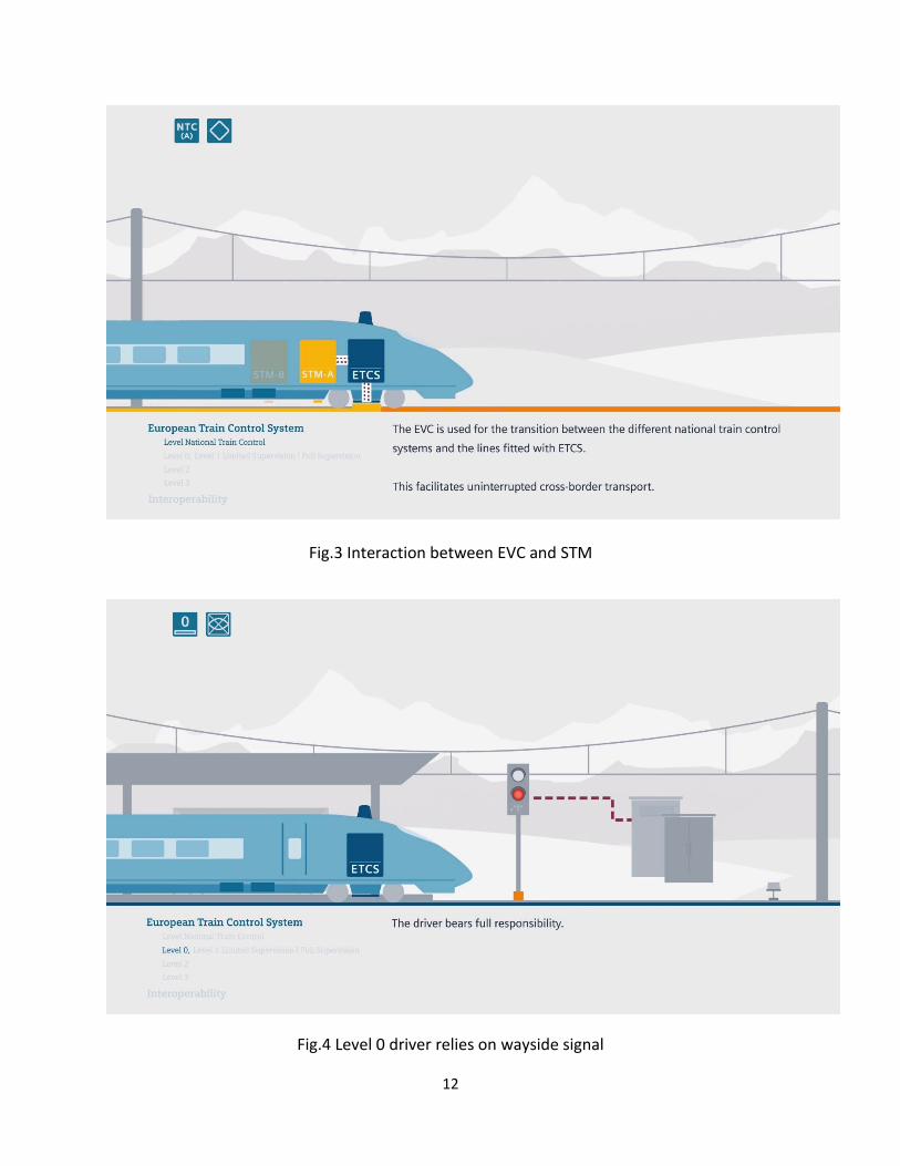
The Level 0 covers operation of ETCS equipped trains on lines not equipped with ETCS or national systems or on lines where trackside ERTMS/ETCS infrastructure and/or national systems may exist but operation under their supervision is currently not possible (e.g. commissioning or on-board/trackside failed components). Train detection and train integrity supervision are performed by the trackside equipment of the underlying signaling system (interlocking, track circuits, etc.) and are outside the scope of ERTMS/ETCS. Level 0 uses no track-train transmission except Eurobalises to announce/command level transitions. Eurobalise therefore still must be read. No Balise data except certain special commands are interpreted (Fig.5) and the driver relies on wayside signal (Fig.4). No supervisory information is indicated on the DMI except the train speed (Fig.4). Train data should be anyway entered in order not to have to stop a train at a level transition to ERTMS/ETCS equipped area and to supervise maximum train speed.
12
Fig.3 Interaction between EVC and STM
Fig.4 Level 0 driver relies on wayside signal

13
Level 1
ERTMS/ETCS Level 1 is a spot transmission based train control system to be used as an overlay of an underlying signaling system. Movement authorities are generated by trackside and are transmitted to the train via Eurobalises (Fig.6, Fig.7, Fig.8).
Fig.5 Level transition initiation by Balise
ERTMS/ETCS Level 1 provides a continuous speed supervision system, which also protects against overrun of the authority. Train detection and train integrity supervision are performed by track circuit or axle counter and are outside the scope of ERTMS/ETCS. Level 1 is based on Eurobalises as spot transmission devices. The trackside equipment does not know the train to which it sends information. If in level 1 a line side signal clears, an approaching train cannot receive this information until it passes the Eurobalise group at that signal. The driver therefore must observe the line side signal to know when to proceed. The train has then to be permitted to approach the stopping location below a maximum permitted release speed. Additional Eurobalises can be placed between distant and main signals to transmit infill information, the train will receive new information before reaching the signal. Line side signals are required in level 1 applications, except if semi-continuous infill is provided. Semi-continuous infill can be provided using Euroloop or radio infill. In this case, the on-board system will be able to show new information to the driver as soon as it is available.
14
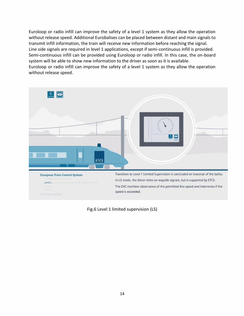
Euroloop or radio infill can improve the safety of a level 1 system as they allow the operation without release speed. Additional Eurobalises can be placed between distant and main signals to transmit infill information, the train will receive new information before reaching the signal. Line side signals are required in level 1 applications, except if semi-continuous infill is provided. Semi-continuous infill can be provided using Euroloop or radio infill. In this case, the on-board system will be able to show new information to the driver as soon as it is available. Euroloop or radio infill can improve the safety of a level 1 system as they allow the operation without release speed.
Fig.6 Level 1 limited supervision (LS)

15
Fig.7 Level 1 Full Supervision (FS)
Fig.8 Level 1 Full Supervision Movement Authorities (MA) can cover several sections

16
Level 2 In ETCS Level 2 (Fig.9, Fig.10), the transmission of variable data between the Radio Block Center and the trains is based on continuous digital radio-based system. In this level, the line side signaling system can be used optionally. It enables safe operation at higher speeds, and provides a near instantaneous update of the movement authority and display cab to driver through Radio Block Center using GSM-R. The Balises are used at this level as spot transmission devices mainly for location referencing. All trains automatically report their exact position and direction of travel to the RBC at regular intervals. Train detection and train integrity supervision are performed by the track side equipment signaling system (interlocking track circuits etc.). The on-board computer continuously monitors the transferred data from Balise including movement authorities, the status and characteristics of the track ahead and the distance to the next Blaise. Between two positioning Balises, the train determines its position via sensors (axle transducers, accelerometer and radar). The positioning Blaise is used as a reference point to calibrate distance measurement errors. The on-board computer also compares the train’s actual speed to the permitted speed. It applies mandatory brake automatically to bring the train speed to below the permitted speed. Level 3 In Level 3, ETCS goes beyond the pure train protection functionality with the implementation of fully continuous radio-based train spacing (Fig.11). Level 2, trains find their position themselves by means of positioning Balises and sensors (axle transducers, accelerometer and radar) and must also can determine train integrity on-board to the very highest degree of reliability (Fig.12, Fig.13). ETCS replaces the line side signals as well as the trackside detection devices. The train driver views all speed and signaling information on in-cab displays and no signals are required along the line as in ETCS The location of the train is determined by the train odometer and reported to the trackside radio block center via the GSM-R radio transmission. In this configuration, the interlocking no longer controls train spacing. It enables the railway to operate at the highest possible capacity. The interlocking and RBC exchange route setting information. The interlocking determines which point on the route the train has safely cleared and grants another movement authority to the following trains up to this point. This configuration offers a great simplification with cost reduction of the equipment in the track and an independence from rigidly structured fixed block intervals. Train headways come close to the principle of operation with absolute braking distance spacing known as moving block.

17
Fig.9 Transition from level 1 to level 2 set up Radio Communication
Fig.10 Movement Authority by RBC VIA GSM-R

18
Fig.11 Transition Level 2 to level 3
Fig.12 The line without track circuit

19
Fig.13 Train running at controlled braking distance
1.2.5 Running level transition
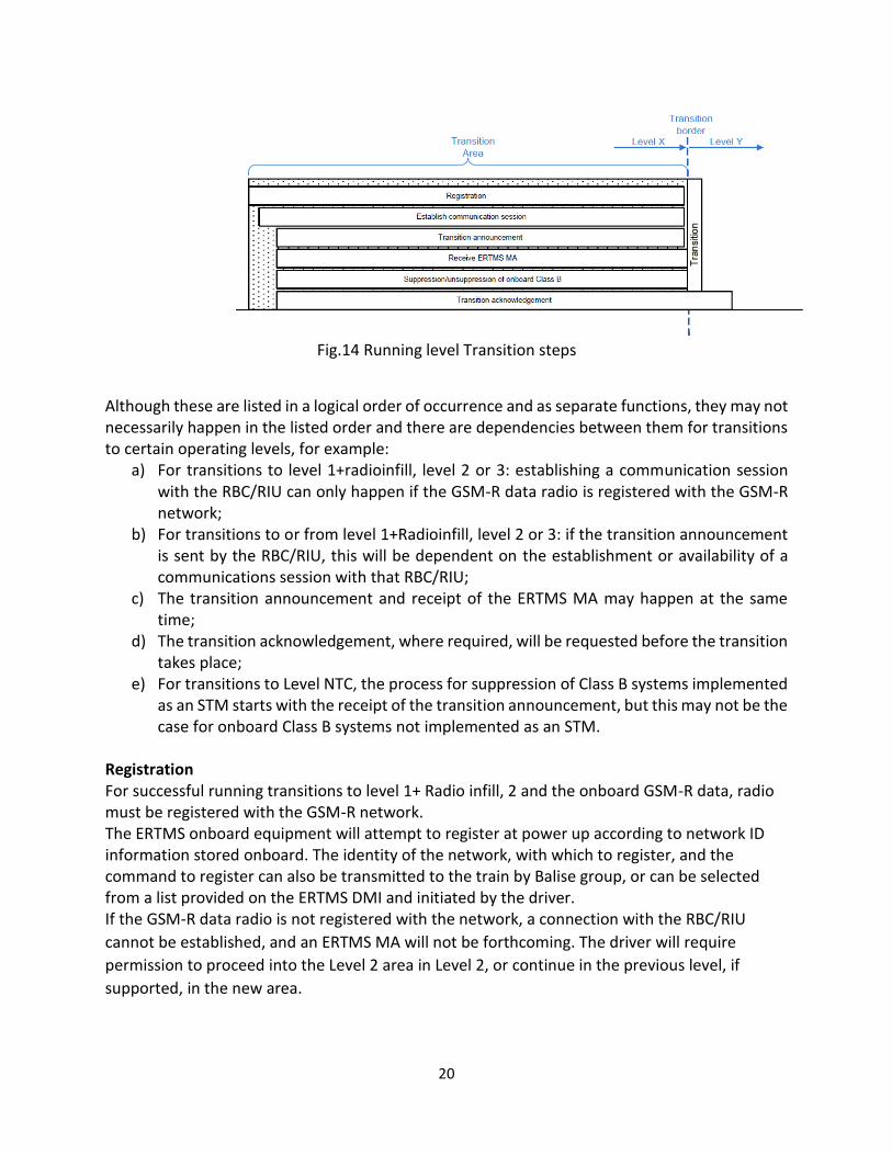
The implementation of ERTMS must support transition between different ERTMS operating levels while a train is on the move. To transition from one ERTMS operating level to another while on the move, depending on the level being transitioned to, some or all the following functions need to take place for the transition to be successfully completed (fig.14):
a) Registration with the GSM-R network (transition to Level 1+Radio infill, 2 and 3); b) Establishment of a communications session with the RBC, RIU (transition to Level 1+Radio
infill, 2 and 3); c) Transition announcement; d) Reception of an ERTMS MA for the move across the transition border and beyond:
necessary for transition to Levels 1 and 2 to avoid entry to TR mode at transition, and for transitions from Levels 1 and 2 to other levels to provide authority to proceed over the boundary in normal operation;
e) Suppression/activation of Class B onboard systems (transitions to/from Level NTC); f) Transition acknowledgement (only required when transitioning between certain levels); g) Transition itself.
20
Fig.14 Running level Transition steps
Although these are listed in a logical order of occurrence and as separate functions, they may not necessarily happen in the listed order and there are dependencies between them for transitions to certain operating levels, for example:
a) For transitions to level 1+radioinfill, level 2 or 3: establishing a communication session with the RBC/RIU can only happen if the GSM-R data radio is registered with the GSM-R network;
b) For transitions to or from level 1+Radioinfill, level 2 or 3: if the transition announcement is sent by the RBC/RIU, this will be dependent on the establishment or availability of a communications session with that RBC/RIU;
c) The transition announcement and receipt of the ERTMS MA may happen at the same time;
d) The transition acknowledgement, where required, will be requested before the transition takes place;
e) For transitions to Level NTC, the process for suppression of Class B systems implemented as an STM starts with the receipt of the transition announcement, but this may not be the case for onboard Class B systems not implemented as an STM.
Registration For successful running transitions to level 1+ Radio infill, 2 and the onboard GSM-R data, radio must be registered with the GSM-R network. The ERTMS onboard equipment will attempt to register at power up according to network ID information stored onboard. The identity of the network, with which to register, and the command to register can also be transmitted to the train by Balise group, or can be selected from a list provided on the ERTMS DMI and initiated by the driver. If the GSM-R data radio is not registered with the network, a connection with the RBC/RIU
cannot be established, and an ERTMS MA will not be forthcoming. The driver will require
permission to proceed into the Level 2 area in Level 2, or continue in the previous level, if
supported, in the new area.

21
Communication session Drivers must not normally be required to enter RBC/RIU contact information as part of a running transition to level 1 + RIU, level 2 and level 3. For transitions to level 1 + RIU, level 2 and level 3 operation only, the ERTMS onboard equipment will need to establish a communication session with the correct RBC. The command for the ERTMS onboard equipment to establish the communication session, and the identity of the network with which to register can be transmitted to the train by Balise group. Connection can only be established if the GSM-R data radio is registered with a GSM-R network. If a connection with the RBC cannot be established, it will not be possible to receive an ERTMS MA for the Level 2 area and it may not be possible to receive the transition announcement. The ERTMS onboard equipment on trains crossing the transition border will still transition to Level 2 without a connection to the RBC, but will subsequently transition to TR mode if coming from Level 0 or Level NTC due to there being no ERTMS MA onboard. Transition announcement All running level transitions must be announced. Only transitions to Levels 2 or NTC require to be announced to the ERTMS onboard equipment via Balise group or via the RBC; this does not preclude announcements for Levels 1 or 0. The ERTMS operational principles and rules require that drivers prepare to apply the rules related to the announced level when the announcement is displayed on the ERTMS DMI. The transition announcement specifies a distance to go to the point where the transition to the new level will be made (transition border) and the table of trackside supported levels beyond the transition border in order of priority (even if only one level is permitted this is considered as a table of priority). The ERTMS onboard equipment will decide to which ordered level the transition will be made, depending on the received priorities and the onboard availability criteria associated with each level, the highest priority available level will be selected. If none of the ordered levels are available, the ERTMS onboard equipment will select the ordered level with the lowest priority. The table of trackside supported levels will be stored by the ERTMS onboard equipment and used to support validation of level during start of mission or manual change of level in degraded situations. The table of trackside supported levels forms part of the information that is invalidated by a transition to NP, which can be automatically revalidated if no cold movement is detected. If the transition announcement will result in a change of level, the ERTMS onboard equipment immediately informs the driver about the approaching change via the ERTMS DMI. The transition announcement can also define the location from which the driver must acknowledge the transition. ERTMS MA for the new level In normal operation, before a fitted train crosses a level transition border from Level 0 or NTC into a Level 1 or 2 area, it must have an ERTMS MA (including the relevant track description, speed profiles and linking information) onboard. Drivers must be provided with the means to determine to an acceptable level of certainty whether this is the case, to avoid the ERTMS onboard equipment entering TR following the transition.

22
An ERTMS MA received by the ERTMS onboard equipment for the new level will only come into effect once the transition to the new level is completed. There is no specified means for drivers approaching a transition border to a Level 2 area to be definitively made aware via the ERTMS DMI that an ERTMS MA has been accepted and is available onboard until the transition to the new level is made unless the transition design provides a means to do so. Examples for how this might be achieved include:
a) If the level transition announcement is only transmitted with the ERTMS MA across the transition border then the announcement of the transition to the driver infers that the ERTMS MA is onboard;
b) A line side signal aspect linked to the issue of an ERTMS MA by the RBC and/or the onboard acknowledgement of receipt of the ERTMS MA could be used to control movements over the transition border. The display proceed of aspect by the line side signal provides a degree of confidence that the ERTMS MA is onboard.
Consideration must be given to the ineffectiveness of RBC based controls when, following a transition from Level 1 to Level 2, a train can continue to operate under the Level 1 MA in the Level 2 area without radio contact with the RBC. For running transitions between levels 1 or 2 an ERTMS MA across the transition border received in the previous level area will remain valid in the new level area if no new level MA is received. So, for example, at a transition from Level 1 to Level 2, a Level 1 MA that extends across the transition border will remain valid after the transition to Level 2 if no Level 2 ERTMS MA is received; the ERTMS onboard equipment will not transition to TR and will continue to supervise the train movements accordingly. It might therefore be possible for a train to continue into the Level 2 area without having established a connection with the RBC and any RBC dependent controls for stopping that train before the End of Authority (EoA) defined in the Level 1 MA will be ineffective.
1.2.6 Operating modes
This part defines the operation modes of ERTMS/ETCS on board equipment and all transition between modes and possible exchange of information between the driver and the onboard equipment. For each mode, the following information is given: a) The context of utilization of the mode and the functions that characterize the mode; b) The ERTMS/ETCS levels in which the mode can be used; c) The related responsibility of the ERTMS/ETCS on-board equipment and of the driver, once the equipment is in this mode. The ERTMS onboard equipment has 17 different operating modes, each of them offers a different degree of supervision and protection. Regardless of the operating mode, before a train movement can start or continue, the driver must have authority to move with a clearly defined limit of authority, and must: a) Continue to monitor the speed of the train against the information available; b) Stop the train at all defined stopping points when required (for example, stations, End of Authority, ERTMS stop markers etc.);
23
c) Maintain a level of awareness that enables them to identify and respond appropriately to intermediate stopping points or potential hazards that would otherwise go undetected by the train systems or that present an immediate danger to the safe operation of the railway (for example, obstructions of the line). A full list of operating modes and a brief description of each is provided in the following sections:
1. Full Supervision (FS); 2. Limited Supervision (LS); 3. On Sight (OS); 4. Staff Responsible (SR); 5. Shunting (SH); 6. Unfitted (UN); 7. Passive Shunting (PS); 8. Sleeping (SL); 9. Stand By (SB); 10. Post Trip (PT); 11. Trip (TR); 12. System Failure (SF); 13. Isolation (IS); 14. No Power (NP); 15. Non-Leading (NL); 16. National System (NS); 17. Reversing (RV).
1. Full Supervision
Full Supervision mode (FS) is applicable in ERTMS application Levels 1, 2 and 3. FS affords the highest level of supervision available within the chosen ERTMS application level and the system design must maximize its use. To be in FS, the ERTMS onboard equipment will require an ERTMS MA that includes movement authority, speed and gradient information. The following characteristics can be used to make up the movement authority information: a) The location of the EoA or Limit of Authority (LoA). If a LoA is defined then a target speed must also be defined; b) Location of the danger point associated with the EoA; c) Location of the end of an available overlap and an associated release timer; d) Release speed associated with the overlap and/or danger point (can be a defined value or instruction to calculate onboard); e) MA sections and associated timers. Should gradient and speed information only be known for part of the train (for example, it only knows the gradient information forwards from a signal or ERTMS stop marker that the train is currently passing), then the train will transition into FS mode, but include a message on the ERTMS DMI indicating that gradient and speed information is not available for the whole length of the train. This message will persist until the train reaches a location where gradient and speed information is available for the whole length of the train.

24
If the gradient and speed information is only known for part of the train, then the operational rules or procedures must define how the driver is to interpret and respond to the associated message that will be displayed on the ERTMS DMI. While in FS the ERTMS DMI will display the following information: a) Current train speed; b) Permitted speed; c) Target speed (depending on the supervision status); d) Distance to go (depending on the supervision status). Other information will be displayed on the ERTMS DMI, but this will be conditional, user defined or dependent upon the operational design (for example, the planning area is an optional feature within the ERTMS specifications). The National ERTMS Program needs to undertake further analysis concerning the available information that can be displayed on the ERTMS DMI to define the system requirements. If the ERTMS onboard equipment detects that the train is travelling too fast or calculates that it is likely to exceed the EoA. The on-board equipment is fully responsible for the train protection except when the driver is responsible for respecting the EoA WHEN APPROACHING AN EoA with a release speed.
2. Limited Supervision
Limited Supervision mode (LS) is applicable in ERTMS application Levels 1, 2 and 3. LS was conceived to be used as part of a transitory step where the underlying signaling system is not life expired and hence full ERTMS infrastructure fitment is not cost effective, but where there is an operational benefit in providing some ERTMS supervision and protection at critical locations when ERTMS fitted trains operate over the line concerned. It can be used to replace older train protection systems that provide similar functionality, creating the opportunity to remove this equipment from trains. LS can provide warnings, over speed and overrun protection, but need not be fitted to every signal. LS (where available) will be commanded by the trackside and indicated on the ERTMS DMI. To avoid a brake intervention the driver will be required to acknowledge a change of mode to LS when transitioning from either of the following modes: a) Standby mode (SB); b) FS; c) On-Sight mode (OS); d) Staff Responsible mode (SR); e) Post Trip mode (PT). When in LS only limited information will normally be displayed on the ERTMS DMI (for example, mode, level, train speed and local time). Other information may be displayed on the ERTMS DMI, but this will be conditional, user defined or dependent upon the operational design. When operating in LS the driver must control the train in accordance with the signaling and speed information provided at the trackside.

25
3. On-Sight On-Sight mode (OS) is applicable in ERTMS application Levels 1, 2 and 3. OS enables the train to enter a track section that could be occupied by another train, or obstructed by any kind of obstacle or enter a track section that is unable to be detected as clear. OS must be used where it is not reasonably practicable to control the movement of a train through the issuing of an FS MA. The method by which OS is offered will be dependent upon the ERTMS application level and ERTMS system design. OS cannot be selected by the driver. In train awakening situations in ERTMS Level 2, OS may be offered to drivers by the RBC if the ERTMS onboard equipment has a valid position. In ERTMS Level 1 the change to OS is commanded from Balise groups. The trackside will command a transition to OS at a defined point or within a defined area, the method by which this will be achieved is dependent upon the application level and system design. Where it is necessary to use OS, the length of the OS MA must be kept to a minimum, with the system design always seeking to issue an FS MA as soon as it is considered safe to do so. To ensure that the driver is aware of an OS MA being offered by the ERTMS system, the transition to OS will be indicated on the ERTMS DMI which the driver must acknowledge. If the driver fails to acknowledge a transition to OS, the ERTMS system will intervene with a service braking application. By acknowledging a change of mode to OS, the driver must understand that they are only authorized to move the train forward at a speed that will enable them to stop short of an obstruction or EoA.
4. Staff Responsible SR is applicable in ERTMS application Levels 1,2and 3. Train movements in SR must only be undertaken when FS and OS are not available, as the ERTMS onboard equipment will supervise the train movement against a nationally defined ceiling speed and, if available, a distance to go. SR will be used in either of the following operational circumstances: a) To pass an EoA without an ERTMS MA; b) During start of mission with an invalid or unknown train position, or where a communications session with the RBC cannot be established. Movements in SR must be authorized by the controlling signaler or the person controlling the move and wherever possible constrained by: a) Limiting the distance, the train can travel in SR based on data stored onboard, received from the RBC or entered by the driver; b) The RBC sending a list of expected Balise groups; c) Balises with a ‘Stop if in SR’ message that will trip a train which passes over in SR (unless the Balise is contained within a list of expected Balise groups, or override is active). In ERTMS application areas where line side signals are provided it may be acceptable from a safety, operational and performance perspective for certain train movements in SR to be authorized using the trackside signaling equipment (that is, the clearing of a signal to a proceed aspect). An example of where this might be acceptable is a driver being permitted to move a train

26
up to a signal displaying a proceed aspect following receipt of SR during start of mission to validate the onboard position and receive an ERTMS MA.
5. Shunting Shunting mode (SH) is applicable in ERTMS application Levels 0, NTC, 1,2and 3. SH allows train movement in either direction. The level of supervision available in SH when operating in Levels 0 and NTC includes ceiling speed supervision. However, when operating in Levels 1 and 2 it is possible to mitigate the risk of overrun by providing automatic stop commands within the Balises protecting the boundaries of a defined shunt area. The system design, operational rules and procedures must mitigate the risks associated with any shunting movement travelling too far. When transitioning to SH an existing communication session with the RBC will be terminated. This will result in any information normally transmitted by the ERTMS onboard equipment to the RBC not being available and any emergency controls that rely upon data communications will not be effective. However, there are occasions when the level of supervision offered by SH may be sufficient to control the risks associated with the movement, for example, when making slow speed movements within a yard, depot, or siding or within an engineering possession. While operating in SH the driver must obey line side signals (if provided) and reach a clear understanding with the signaler/shunter before any movement commences. The ERTMS/ETCS on-board equipment is responsible for the supervision of the shunting mode speed limit, and that the engine with the active antenna is tripped when passing the defined border of the shunting area (only if there is a defined border: Balise group not in the list given by trackside, or Balise group giving the information stop if in shunting). The driver is responsible for: a) Remaining inside the shunting area defined by a procedure or an external system outside ERTMS/ETCS (also when the shunting area is protected by Balises); b) Train/engine movements and shunting operations.
6. Passive Shunting Passive Shunting mode (PS) is applicable in ERTMS application Levels 0, NTC, 1 and 2, and 3 is provided to: a) Manage the ERTMS onboard equipment of a running hauled locomotive, neither remote controlled nor providing traction power but mechanically coupled to the leading locomotive; b) Facilitate the continuation of a shunting movement with a single locomotive or fixed formation multiple unit fitted with one ERTMS onboard equipment and two cabs when the driver must change the driving cab. PS is an extension of SH, that when selected by the driver will prevent ERTMS onboard equipment in SH mode transitioning to Standby mode when the driving desk is closed, allowing SH to be available immediately when the cab is reopened for further shunting moves. Traction units operating in PS must be prevented from entering SH when the cab is opened in areas where SH operations cannot be safely carried out. The ERTMS/ETCS on-board equipment of an engine in Passive Shunting mode has no responsibility for the train protection.
27
The notion of responsibility of the driver is not relevant for the Passive Shunting mode. Note: The leading engine is responsible for the movement of the train. It is then the ERTMS/ETCS on-board equipment of the leading engine that is fully/partially/not responsible for the train protection, with respect to its mode.
7. Unfitted Unfitted mode (UN) is applicable in ERTMS application Level 0. Unfitted mode is applicable in areas not equipped with ERTMS/ETCS trackside equipment nor with national train control are system or areas equipped with ERTMS/ETCS OR NATIONAL equipment but it is not possible to operate under their supervision. Unfitted mode (UN) is applicable in ERTMS application Level 0. The level of supervision available in UN includes ceiling speed supervision. In addition to ceiling speed supervision it is possible to provide supervision for Temporary Speed Restrictions (TSR).
8. Isolation Used in all levels: Level 0, level 1, level 2, level 3 and level NTC. IS will be entered when the ERTMS onboard equipment has been isolated using the ERTMS isolation switch, in this mode the on-board equipment shall be physically isolated from the brakes and can be isolated from other onboard equipment depending on the specific on board equipment is isolated. When in IS a traction unit must be capable of being hauled. The operational rules and procedures must define how a train in isolation is to be moved. The driver must be provided with current train speed information for operations in isolation. Isolation of the equipment is under complete responsibility after isolation of onboard equipment has no more responsibility.
9. Non-Leading Non-leading mode (NL) is applicable in all levels: Level 0, level 1, level 2, level 3 and level NTC. NL is designed to facilitate tandem working and can be used for banking movements (that is, where two or more ERTMS fitted traction units’ form part of the same train formation but are not electrically connected and require a driver on each traction unit) and is the ERTMS operating mode used by other than the leading traction unit. The ERTMS onboard equipment requires a ‘non-leading input signal’ from the train interface as a necessary condition to enter NL. The ERTMS onboard equipment will not perform any train movement supervision in NL - supervision for an associated train movement being provided by an ERTMS onboard equipment (or onboard Class B systems) elsewhere within the train formation. The ERTMS/ETCS on-board equipment shall perform NO protection functions, except forwarding track conditions associated orders through DMI or train interface. The driver is responsible for obeying the orders associated to track conditions, when they are displayed by the DMI.

28
10. Trip Trip mode (TR) is applicable in ERTMS application Levels 0, NTC, 1, 2 and 3. A transition to TR will be initiated automatically when: a) Commanded by the trackside; b) The ERTMS onboard equipment detects that the train has passed beyond the point to which it was authorized to move; c) The ERTMS system can detect that the safety of the train, if it continues, might be at risk. Upon entering TR, the ERTMS onboard equipment will command an emergency brake application. All MA information and track description data held onboard will be deleted and no new data will be accepted. The emergency brake demand will remain active until the train has come to a standstill and the driver has acknowledged the transition to TR. The ERTMS onboard equipment will indicate to the driver, via the ERTMS DMI, the reason for the transition to TR. The information presented to the driver on the ERTMS DMI must be sufficient to enable the cause of the event to be identified. In Level 2 operation, where a communication session with the RBC is, or can be established, the ERTMS onboard equipment will automatically report a transition to TR to the RBC which must be indicated to the signaler to make them aware of a potentially hazardous situation. The driver must interpret a transition to TR as a hazardous situation and take all necessary action to safeguard the train and other users of the railway (including reporting the event to the controlling signaler). If the signaler becomes aware of a transition to TR, then they must take all necessary action to contain the incident. Transition to TR can occur for many reasons, not necessarily exceedance of the EoA, therefore unless the system can distinguish an EoA trip it is not reasonable to automatically trigger overrun management for a TR event. Once the affected train is at a standstill and the driver has acknowledged the transition to TR, the ERTMS onboard equipment will automatically transition to Post Trip mode, except when operating in ERTMS application Levels 0 and NTC. When operating in ERTMS application Level 0 or NTC upon acknowledgement of the transition to TR, the ERTMS onboard equipment will automatically transition to SH, UN or National System mode (SN). The mode to which the ERTMS onboard equipment will transition is dependent on the presence of valid train data and the ERTMS operating mode being used prior to the TR event occurring. If the ERTMS application Level is 0 or NTC, the ERTMS onboard will transition to UN or SN respectively if valid train data is held, otherwise it will transition to SH. All transitions to TR must be investigated to understand the circumstances surrounding the event. The national operational rules must define the arrangements for recovering from a transition to TR taking into consideration the risks associated with each of the possible causes. The ERTMS/ETCS on-board equipment is responsible for stopping the train and for maintaining the train at standstill. The driver has no responsibility for train movements.

29
11. Post trip Reversing mode (RV) is applicable in ERTMS application Levels 1, 2 and 3. There may be occasions when it may be advantageous to make reverse movements without the need to change driving cabs or enter SH (for example, to facilitate routine shunting movements that involve propelling movements). There are potential safety benefits available for movements in RV in comparison with SH as the driver is presented with target distance information. The application of ERTMS must include all areas where RV is authorized and these areas must be defined in local publications and be indicated on the ERTMS DMI. The ERTMS trackside equipment will announce an area where RV is authorized in advance to the ERTMS onboard equipment. The level of supervision available in RV includes ceiling speed supervision and distance to go supervision. The ERTMS DMI will display the train speed, the permitted speed and remaining distance to go. However, the driver must not regard the permitted speed and distance to go as targets, as it is the driver’s responsibility to limit the distance to be travelled in RV to an absolute minimum and at a speed that enables the train movement to be stopped short of any obstruction, or when instructed to do so by the person controlling the movement. Entry to RV does not change the train orientation and the distance to run is supervised against the front of the train rather than the rear. The ERTMS onboard equipment will command the emergency brake once it has detected that the front of the train has exceeded the permitted reversing distance. Once the train is at a stand, the ERTMS onboard equipment will prevent any further movement in the reverse direction. The national operational rules must define when RV is authorized for use and how exceedance of the distance to go is to be managed. In addition, the ERTMS National Program must undertake further analysis to determine whether RV should be used in an emergency to enable drivers to take evasive action if a train movement exceeds an ERTMS movement authority and enters a conflict area. The ERTMS/ETCS on-board equipment is responsible for supervising that the train moves only backwards and that the backward movement does not exceed the maximum permitted distance (national value). The driver is responsible if moving the train backwards.
12. Sleeping Sleeping mode (SL) is applicable in ERTMS application Levels 0, NTC, 1, 2 and 3. Train movements in SL will be normal where multiple working is required (that is, where two or more fitted traction units are coupled physically and electrically and where only one driver is required to control the train). Transition to SL will be automatically initiated when the ERTMS onboard equipment detects that a driving desk has been opened that is associated with another ERTMS onboard equipment elsewhere in the train formation (that is, the train is being driven from another ERTMS fitted traction unit within the train formation). Once an ERTMS assembly has transitioned to SL, it will remain in SL until either the sleeping input signal is lost and the train is at a stand, or the driving desk is opened. The ERTMS onboard equipment will then automatically transition to SB.

30
As a minimum, the sleeping input signal must be lost if the traction unit becomes uncoupled from the rest of the train (for example, during uncoupling activities or divided train scenarios). The ERTMS onboard equipment receives the sleeping input signal via the train interface. Functionality for detection of uncoupling therefore relates to the integration of ERTMS within the vehicle rather than a requirement on the ERTMS onboard equipment so in this case the leading engine is the responsible for the movement of the train, then the onboard equipment of the leading engine is not fully or partially responsible for the train protection, respect to its operating mode.
13. Stand by SB is applicable in ERTMS application Levels 0, NTC, 1, 2 and 3. Transition to SB will be automatically initiated when the ERTMS onboard equipment is powered up. If a fault has been detected it may subsequently transition to System Failure mode (SF). SB will be the default operating mode for the ERTMS onboard equipment and is the initial mode used at the start of mission process. Train movement must be permitted in SB to facilitate coupling and uncoupling activities. Facilitating such movements in SB eliminates the need for any interaction with the ERTMS DMI, as there is no requirement for the driver to select an alternative mode or input any train data, thus providing similar levels of productivity to those experienced when operating unfitted trains. However, safety is improved through the provision of standstill supervision In standby mode The on-board equipment is responsible for maintain the train at standstill.
14. System Failure SF is applicable in ERTMS application Levels 0, NTC, 1, 2 and 3. The detection of a safety critical fault by the ERTMS onboard equipment will cause it to transition to SF except, where possible, if the ERTMS onboard equipment is operating in NL, PS, or SL modes. Transition to SF will cause the ERTMS onboard equipment to automatically command an emergency brake application. If the affected ERTMS onboard equipment is operating in NL or SL when the safety critical fault is detected, then the system must record and display the details of the fault if possible and automatically transition to SF upon exiting NL or SL. The powering down of the affected ERTMS onboard equipment will cause a transition to NP. Transition to NP might clear an intermittent fault within the ERTMS onboard equipment and therefore remove the need to isolate it In system, operating mode the onboard equipment is responsible of commanding the emergency brakes.
15. Reversing Reversing mode (RV) is applicable in ERTMS application Levels 1, 2 and 3. There may be occasions when it may be advantageous to make reverse movements without the need to change driving cabs or enter SH (for example, to facilitate routine shunting movements that involve propelling movements).

31
There are potential safety benefits available for movements in RV in comparison with SH as the driver is presented with target distance information. The application of ERTMS must include all areas where RV is authorized and these areas must be defined in local publications and be indicated on the ERTMS DMI. The ERTMS trackside equipment will announce an area where RV is authorized in advance to the ERTMS onboard equipment. The level of supervision available in RV includes ceiling speed supervision and distance to go supervision. The ERTMS DMI will display the train speed, the permitted speed and remaining distance to go. However, the driver must not regard the permitted speed and distance to go as targets, as it is the driver’s responsibility to limit the distance to be travelled in RV to an absolute minimum and at a speed that enables the train movement to be stopped short of any obstruction, or when instructed to do so by the person controlling the movement. Entry to RV does not change the train orientation and the distance to run is supervised against the front of the train rather than the rear. The ERTMS onboard equipment will command the emergency brake once it has detected that the front of the train has exceeded the permitted reversing distance. Once the train is at a stand, the ERTMS onboard equipment will prevent any further movement in the reverse direction. The national operational rules must define when RV is authorized for use and how exceedance of the distance to go is to be managed. In addition, the ERTMS National Program must undertake further analysis to determine whether RV should be used in an emergency to enable drivers to take evasive action if a train movement exceeds an ERTMS movement authority and enters a conflict area. In RV mode, the onboard equipment supervises a ceiling speed and a distance to run in reverse direction and the deriver must keep the train movement inside the received distance to run.
16. No Power NP is applicable in ERTMS application Levels 0, NTC, 1, 2 and 3. A transition to NP will be initiated automatically when the normal power supply to the ERTMS onboard equipment is interrupted (for example, during train disposal duties or by use of the ERTMS reset button). Although a transition to NP will cause all previously entered data to be lost, the ERTMS onboard equipment will monitor train movements through cold movement detection. When in NP the ERTMS onboard equipment will permanently command an emergency brake application. Therefore, if it is required to move while in NP then the emergency brake command must be overridden by an external means. In this case, obviously the onboard equipment has nothing responsibility, just commanding the emergency brake and optionally monitoring cold movement. If it is necessary to move locomotive in NP mode as a wagon ERTMS brake command must be overridden by external means.
17. National System NS is applicable in ERTMS application level NTC.

32
In NS, no train supervision functionality is provided by the ERTMS onboard but according to the specific onboard implementation the national system may access the following resource through ERTMS/ETCS onboard equipment Driver Machine Interface (DMI), Juridical Recording interface, odometer, train interface and brakes. This can be achieved through the STM interface. The National System is responsible for maintaining national system behavior and interact with national trackside equipment, supervision and protection function, issuing and revoking brake command and interaction with driver. The responsibility of the driver depends on the National System in use.
1.2.7 Message language
For transmitting the information by the radio communication, ERTMS/ETCS uses language based on variables, packets, massages and telegrams. Variables The variables are the simplest information. Every variable has a type, meaning and a unique name and can only contain a fixed set of values. The nature of the information is digital, for which the variables are composed of bit strings of variable length depending on the type. In base of the information type that contain variable, the name of variable will be different and they have different prefix: A_ Acceleration D_ Distance G_ Gradient L_ Length M_ Miscellaneous N_ Number NC_ Class Number NID_ Identity number Q_ Qualifier T_ Time/date V_ Speed X_ Text
Packets The packets are the set of grouped variables in a single unit with a defined internal structure. This structure consists of a packet header with Track to Train and Train to track a unique packet number, the length of the packet in bits, the orientation information, optionally the distance scale and an information section containing a defined set of variables. There is no Q_SCALE variable in packets which do not contain distance information. The packet definition does not change when transmitted over different transmission media. Each package is formed by a header, with the variables that represent the type and length of the package and a payload, with the variables that contain the actual information to be transmitted.

33
Each packet is uniquely identified by an 8-bit code, namely by a number from 0 to 255, contained in the variable NID PACKET this header. In the current version of the language ETCS can be distinguished about 100 different packages, such as those useful for the purposes of the radio infill are described in the table 1. Exception: Packet 0 Virtual Balise Cover marker and Packet 255: End of Telegram do not follow the above defined structure. N_ITER specifies the number of iterations of a variable or group of variables which follow. If N_ITER is 0 then no variables follow. Two nested levels of iterations can exist. If, depending on the value of a previous qualifier variable in the packet, a variable is optional, it is written indented in the packet definition Row Transmitted by in the description of a packet specifies which ERTMS/ETCS trackside device (Balise, loop, RIU, RBC) can transmit this packet. Any means that the packet can be transmitted by a Balise, a loop, an RBC and a RIU (table 2). If infill information contains an announcement of an immediate level transition at the reference location of the infill information, for the distance D_LEVELTR the value of 0m shall be used. For infill, only distance based information can be interpreted on-board.
Table 1 Infill Information

34
1.3 System for Mobile Communications – Railway (GSM-R) Harmonization of railways is an important task for the further improvement of European infrastructure. Harmonization of telecommunications in railway operation, with the goal of full interoperability, is a key element. And a harmonized interoperable system in Europe is expected to open the way to global harmonization. The European authorities have selected GSM-R as the transmission technology. This is defined in the European Directive on High Speed Train Interoperability and by other forthcoming European Directives for railways (including the European Directive on Conventional Lines interoperability), with standardization being a key to achieving a harmonized solution.
Table 2 Information transmitted by loop or RIU
GSM-R uses the GSM technology, but the specialized requirements for harmonized railway operation, for high-speed trains, means that applications must use the GSM system in a specific way. Data transmission is achieved by continuous radio transmission (GSM-R). For some functions, the radio transmission requires complementing by spot transmission (Eurobalise). The detection of trains is achieved by equipment onboard, reporting to the control command trackside assembly. Signaling information is communicated to the driver by equipment in the driving cab.

35
Data transmission is achieved by spot transmission (Eurobalise) and in some cases by semi-continuous transmission (Euro loop or radio in-fill). The detection of trains is achieved by track-based equipment, usually track-circuits or axle counters. Signaling information is communicated to the driver by equipment in the driving cab and, optionally, line side signals. Below, it is presented the GSM-R system, a key part of the ERTMS project relating to
telecommunications, both voice and data, between the train and ground bases. After a brief
introduction on the history and reference standards, they describe the technical and functional
specifications, types of terminals and the architecture of the GSM-R system.
1.3.1 History and reference standards
GSM-R is an extension of GSM technology, by adding functionality specifically for railway applications. The GSM-R standard is the result of collaboration between different railway companies and European telecommunications industries with the aim of creating a unique and interoperable standard, able to take over all the functions required in the railway sector, through an economically feasible and widely developed. The regulatory framework for the GSM-R is composed mainly by Directive 1991/440/EC on the development of the Community's railways and the Directive 2008/58/EC on the interoperability of Community rail. The First Directive contains statements of intent and programmatic objectives for the European railway telecommunications system, including:
• The need to have an open telecommunications system, standard and not depending upon the owner;
• Achieve interoperability throughout Community territory; foster the development of an open and competitive market among operators of the sector;
• Support the development of new train control technologies;
• Efficiently manage and secure way voice and data communications between trains and the ground control centers.
In the second directive, GSM-R system is presented, along with ETCS, as a fundamental component of the ERTMS project and references are provided the technical specifications for interoperability and functional requirements, system and interface, realized in the context of the European Integrated Projects Rail Enhanced Network (EIRENE) and Mobile Radio for railway Networks in Europe (MORANE). EIRENE system is a railway telecommunications system based on the ETSI GSM standard, which complies with all related mandatory requirements as specified in the EIRENE FRS and SRS. An EIRENE system may also include optional features and these shall then be implemented as specified in the EIRENE FRS and SRS. The EIRENE System includes terminals.

36
1.3.2 Network requirements
The network services necessary to meet the range of UIC requirements are detailed below. These services are to be considered as a minimum set for implementation within each UIC standard network. Railways may implement additional network services as desired. Voice services This section describes the generic voice telephony services which shall/should be supported by the EIRENE network:
• Point-to-point voice calls; • Public emergency voice calls; • Broadcast voice calls; • Group voice calls; • Multi-party voice calls.
All voice call services shall be able to operate between any combination of fixed and mobile equipment users (excluding specific data terminal equipment). Point-to-point voice calls The system shall support point-to-point voice calls between any two call parties. Such point-to-point calls shall allow both parties to talk simultaneously. Public emergency voice calls The system shall allow a user to make public emergency point-to-point voice calls. Such emergency calls include 112 calls and may not be used for railway emergencies. Broadcast voice calls The system shall support broadcast voice calls. Broadcast voice calls provide one-way voice communications from a single user to multiple users in a pre-defined local area, all of whom are members of the same call group. The composition of call groups shall be able to be modified within the network. A single user shall be able to be a member of one or more call groups. The local area over which broadcast calls shall be implemented shall be able to be modified within the network. It shall only be possible for the user who initiated the call to talk, other users can only listen. Group voice calls The system shall support group voice calls. Group voice calls provide voice communications between several users in a pre-defined local area, all of whom are members of the same call group. The composition of call groups shall be able to be modified within the network. A single user shall be able to be a member of one or more call groups. The local area over which group calls are implemented shall be able to be modified within the network. It is acceptable that only one mobile user involved in the group call may talk at any time. In this case:
• It shall be possible for controllers to speak at any time during the call;
37
• A mechanism shall be provided by the system to arbitrate between those users wishing to speak within the group call.
Multi-party voice calls The system shall support multi-party voice communications between up to six different parties. Any of the parties involved in a multi-party voice call shall be able to talk simultaneously. Data services The EIRENE network shall/should provide data services to support the following data applications:
• Text messages;
• General data applications;
• Automatic fax;
• Train control applications. Text messages The network should support the transmission of point-to-point and point-to-multipoint text messages from the ground to mobile users. The network should support the receipt of mobile-originated text messages by the ground. If the text message facility is implemented, it shall not interfere with the ability of users to make or receive calls with a higher priority. General data applications Support is required for a range of data communications between the ground and mobile users. Such applications may include:
• Timetable information;
• Maintenance and diagnostic applications;
• E-mail;
• Remote database access. The network shall support point-to-point data communications. The network shall support data rates of at least 2.4 Kbit/s. higher data rates will be required by some data applications to provide the necessary performance and acceptable transmission times.
Automatic fax The network should support fax transmissions between the ground and mobile users. Where fax functionality is provided, it shall be possible to interrupt the fax to make or receive calls with a higher priority. Train control applications Where ERTMS/ETCS level 2 or 3 is implemented, the network shall be capable of supporting data communications for that train control system with the required quality of service. Communications for train control may be characterized as low data rate per train; however, in some areas there will be a high density of trains requiring simultaneous communications.
38
Call related services The EIRENE network shall/should support the following call related services:
• Display of identity of called/calling user;
• Restriction of display of called/calling user;
• Priority and pre-emption;
• Call forwarding;
• Call hold;
• Call waiting;
• Charging information;
• Call barring;
• Explicit call transfer;
Display of identity It shall be possible to display the identity of the called or calling party in the form of a standard telephone number. It shall be possible to display the identity of the called or calling party as a textual description of their function. Restriction of display of identity: it should be possible for the network to prevent the identity of certain users from being displayed on the mobile, either when being called, calling or both. Priority and pre-emption The network shall provide a mechanism whereby calls may be assigned to a number according to different priority levels. This mechanism shall allow calls with a higher assigned priority to override (pre-empt) existing calls of a lower priority. Pre-empted calls will be discontinued and the new call of a higher priority shall be connected instead. Call forwarding It shall be possible for an incoming call or data message for one user to be forwarded to another user using functionality provided by the network. There are several sub-classes of automatic call forwarding for the incoming call, which shall/should be supported by the network:
• Without any user interaction (unconditional);
• Without user interaction if the user is busy in an existing call (busy);
• Where there is no reply from the intended recipient (no reply);
• When intended recipient cannot be contacted via the network (not reachable). Call hold The network shall allow the user to temporarily exit from an existing call by putting the call on hold. It shall be possible for the user to re-join the call which is on hold at any time. Call waiting The network shall provide the ability to inform a user, who is involved in an existing call, of attempts by other users to contact them.
39
Charging information Where network services are chargeable, it should be possible for the network to provide information about call rates and on-going call charges. Call barring It shall be possible, using network management or maintenance facilities, to prevent individual users from:
• Making calls to:
• Another network (fixed or mobile);
• Certain types of numbers within or external to the network;
• Certain pre-defined telephone numbers;
• Receiving calls from:
• All other networks (fixed or mobile);
• Certain other networks (fixed or mobile);
• Certain types of numbers within or external to the network;
• Certain pre-defined telephone numbers. Explicit call transfer It should be possible to transfer an incoming call or call in progress to another party. It shall be possible for the user who is attempting to transfer a call to converse with the intended recipient prior to transferring the call. Railway specific services The EIRENE network shall also provide support for the following railway specific services: functional addressing including registration/deregistration; Location dependent addressing; Railway emergency call; Functional addressing An addressing scheme shall be provided which permits users to be identified by numbers corresponding to their functional roles rather than by numbers tied to the terminal equipment that they are using. The primary usage of functional addressing will be for controllers to establish communications with train drivers by making use of the train number. The train number will vary between journeys although EIRENE equipment in the cab is unlikely to change. Other uses of functional addressing will include identifying on-train functions and other users performing roles such as shunting team leaders, maintenance team members, etc. It shall be possible to assign up to a minimum of 3 functional numbers to an EIRENE user at any one time. User shall be able to set up a functional number on one network, and cancel the number from another network. The functional number shall remain valid as a user roams from one network to another.
40
The functional addressing scheme shall be independent of specific configurations of mobile and terminal equipment. For example, the functional number of a conductor on board a train shall be the same irrespective of whether the conductor accesses the network through the Cab radio or has a separate dedicated EIRENEo-bile. It shall be possible to call EIRENE users by functional numbers from a wide range of terminals (EIRENE and non-EIRENE). Examples include EIRENE mobiles, controller terminals, railway fixed network telephones and public telephones. The functional addressing scheme should permit calls to be routed from a controller to an international train within the control area without reference to any EIRENE system other than that providing service to the international train. Location dependent addressing Location dependent addressing shall be provided to route calls for a given function to a destination number that is dependent upon the user’s location. The functions to which calls shall be routed based upon the location of the mobile shall include:
• Primary controller;
• Secondary controller;
• Power supply controller;
• Train management centre (ex. RBC). The correspondence between the locations and the destination of the call must be easily re-configurable to support dynamic changes in controller area boundaries (e.g. controller area boundaries will change from peak to off-peak periods during the working day or over longer periods, areas may change to match changes in railway organization or traffic demand). When operating with location dependent addressing, no manual action shall be required to update the system when a mobile move between locations except at border crossing. The location dependent addressing scheme shall be available to all mobiles. As a minimum, the location information used by the EIRENE system shall be derived from that available from the network itself (e.g. current cell or base station serving the mobile). Where greater accuracy for location dependent addressing is required, additional location information may be provided by systems external to EIRENE. Sources of such information may include:
1. Ground-based signaling systems; 2. On-train systems (e.g. ERTMS/ETCS equipment, Balise readers, GPS etc.)
Railway emergency calls Railway emergency calls covers the use of the radio system for Railway emergency calls. This section also describes the facility for confirmation of such emergency calls and storage of confirmation for post-incident analysis. Types of Railway emergency calls, there are two types of Railway emergency call:
• Train emergency call;
• Shunting emergency call.

41
The type of call initiated shall be determined automatically, based upon the mode of operation of the radio. If the mobile is in shunting mode, the emergency call button shall initiate a shunting emergency call, otherwise the call shall be a Train emergency call. Train emergency call The Train emergency call shall be sent for warning all drivers, controllers and other concerned personnel of a dangerous situation in a pre-defined area. The appropriate ERTMS/ETCS RBC should be informed when a Train emergency call is initiated. Shunting emergency call The goal of shunting handheld radio specification is for railways to unite and to agree on a common terminal platform. This common terminal platform should have interfaces, applications and accessories to fulfil specific national railway needs. The Shunting emergency call shall be sent to all users involved in shunting operations in the shunting area. The Shunting emergency call shall automatically take priority over the link assurance signal. Type of voice calls specific to railways
• Railway Emergency Call;
• Railway Emergency Call as described previously;
• High Priority calls. High Priority call Shall be associated with an internationally harmonized value (such as Short Dialing Code, Group Identity or Functional Number). A mobile user or a controller shall be able to initiate a High Priority call. A High Priority group call shall be terminated by the originator or an entitled controller. A High Priority point to point call shall be terminated by the originating or the terminating party. The connectivity matrix for High Priority calls defines which subscribers can contact which other subscribers within the EIRENE network. Yes, indicates that the network shall allow a call from the stated initiating party to the stated receiving party. Shaded cells on the connectivity matrix mean that this call is outside the scope of the EIRENE specification
1.3.3 Mobile equipment core specification
Five distinct mobile radio types are required, based on the type of role they will perform and the environment in which they will operate, as follows:
1. Cab radios for the transmission of voice and non-safety data, for use by the driver of a train and/or by other on-train systems;
2. General purpose radios, for general use by railway personnel; 3. Operational radios, for use by railway personnel involved in operations such as trackside
maintenance. 4. Shunting radio, for use by railway personnel involved in train operations such as
shunting. 5. ETCS data only radios, for the transmission of train control data.
42
The GSM-R system uses a band specially reserved for applications railway (876-880 MHz, 921-925 MHz), but must be able to work even in the extended GSM commercial band (880-915 MHz, 925-960 MHz). In addition, because the GSM-R terminals will be installed mainly on high speed trains, will have to be guaranteed the proper functioning of speed system up to a maximum of 500 km/h, with respect to the limit of 250 Km/h provided in the GSM standard.
1.3.4 Network configuration
For the EIRENE network and the performance levels which are to be achieved. The aim is to provide interoperability between networks and a consistent level of service. It may be necessary to supplement this Functional Requirements Specification with special requirements for supporting the train control application. Further information on the communications requirements to support ERTMS can be found in the Summary of ERTMS Communication Requirements document. Coverage and performance For network planning, the coverage level is defined in terms of time and area where the minimum signal criteria are achieved. The level of coverage should be at least 95% of the time over 95% of the designated coverage area for a radio installed in a vehicle with an external antenna. The network shall support all EIRENE-compliant mobiles.
1.4 European Traffic Management Layer (ETML)
The operation management level intended to optimize train movements by the intelligent interpretation of timetables and train running data. It involves the improvement of real-time train management and route planning rail node fluidity customer and operating staff information. The deployment of a unique harmonized train command/control and telecommunication systems and the creation of Trans European traffic management facilities constitute crucial elements toward the achievement of a real integrated rail network. Railways, as guided ground systems, use a dedicated infrastructure. Their attractiveness and efficiency depend, to a large extent, on the underlying means and methods for traffic management and on the ability to maximize the capacity and throughput of different types of traffic in a consistently safe and reliable manner. The main purpose of ERTMS and unify the rail control systems and control, national telecommunications and logistics, historically different and incompatible between them, and to obtain in practice the only theorized interoperability in European directives.
43
Chapter 2
2 Radio Infill Unit description and requirements
Radio In-fill is a function that can be optionally added to ERTMS Level 1 to increase the
performance of the line. The purpose of the Radio Infill Unit is to transmit the message
corresponding to a Eurobalise in advance to the train. In this way, a train approaching the
application zone of a more restrictive condition can revoke braking as soon as the signal clears
without waiting to reach the Balise itself. The infill message is transmitted via radio using GSM-R
and Euroradio safety protocols (This section provides a precise specification of the safety protocol
considering the CENELEC standard EN 50159 [8]. The method used in the SFM corresponds to the
A1 type in EN 50159 [8]: cryptographic safety code using secret key) as used in ERTMS Level 2.
The use of radio allows continuous infill coverage for data radio equipped trains on fitted sections
between Balises. The RIU consists of the following parts:
1) A redundant vital safety management subsystem, based on proprietary 2-out-of-3 architecture
and SIL 4 certified, supporting:
• Message encryption and decryption, according to EURORADIO specifications;
• Movement Authority Management;
• Human Machine Interface.
The RIU may be interfaced using safety related protocols and Interlocking, with flexibility on the
total number of interfaces Here are the principles, functionality, and the system requirements
RIU, in accordance with (European Railway Agency, ERTMS/ETCS: System Requirements
Specification, Version 3.4.0) [4] and UNISIG, Radio in-fill: Form Fit Functional Specification,
Version 2.0.0 [11] and examples of typical applications are provided.
2) A redundant Non-Vital management subsystem based on commercial hardware architecture,
including:
• Events recording and diagnostics, connected to the Maintenance Management System;
• Remote supervision and/or CTC interface.
2.1 Principles
The RIU can repeat the signals associated with one or more groups of Balises, so it can simultaneously communicate with one or more trains equipped with Euroradio. Communications simultaneously managed by the RIU with more trains are all point-to-point, since It is not expected the possibility of transmission communications. In addition, the RIU is not able to start and establish independently a connection with a train, the on-board shall establish a communication session At Start of mission with RIU. We should know if there are more than one train on the same block section only the first one is able to receive the infill information so the following trains on the same block section are not able to continue in full supervision mode.

44
Just a functional interface with LEU/Interlocking is necessary, to acquire the signalling information associated with the next main signal.
2.2 Integrity of data consistency
The safety and reliability of radio communications between the ground and the train, as for ETCS
level 2 and 3, they are guaranteed by the Euroradio protocol, but the RIU must ensure the
integrity and consistency of the data transmitted, based on the following criteria:
• Correct syntax: All messages must be comprehensive, to respect the established syntax
and valid values;
• Temporal coherence: the time and date sent (timestamp), present in any previous
message, must be antecedent to those of each next message;
• Consistency of recipient: each message is valid only if received the correct recipient. As it regards the second point, the reference time is always that of the train, to which the RIU
must estimate this time, in the most accurate as possible, based on the timestamp of the last
received. To do this, it is necessary a RIU, which has an independent timer, recalibrated at each
message received from the train.
It is up to the sub-board system to verify the temporal coherence of the messages received,
discarding any messages with timestamps less than or equal compared to previous messages.
2.3 Interfaces
ETCS is a system studied to exist in cooperation with other systems and devices. Therefore, for
data exchanges between devices in the system, it is necessary to use different interfaces
trackside: for example, the air gap interface is used for data exchange between track and the
train, the wayside interface C between LEU and the Eurobalise and so on.
The Eurobalise Transmission System consists of the (wayside) Balise and the On-board
Transmission Equipment that is part of the ERTMS/ETCS On-board constituent. Balises are of
either fixed type or controlled type. The On-board Transmission Equipment consists of the
Antenna Unit and BTM function. The Wayside Signaling Equipment consists of the LEU and other
external equipment involved in the wayside signaling process.
The On-board Transmission Equipment communicates with the ERTMS/ETCS Kernel. The Balise
communicates with the Wayside Signaling Equipment via Interface C. The LEU (part of the
Wayside Signaling Equipment) communicates with the wayside signaling or interlocking via the
non-standardized Interface S as shown in figure 15.
45
2.3.1 External interface group
In the external interface group, there is just one preferred standardized interface called C,
defined as a way side interface the main task of interface C is to receive and send telegrams
between LEU/Balise and LEU/SMR. The Interface C is divided into different sub-interfaces
according to functionality:
• C1: for transmitting Up-link Eurobalise telegrams from the LEU to the Balise;
• C2: for transmitting Down-link Eurobalise telegrams from the Balise to the LEU;
• C3: for supplying the Down-link Balise with power from the LEU;
• C4: for inhibiting switching of telegrams in the LEU during a Balise passage;
• C6: for biasing the serial interface (C1) input circuits of a controlled Up-link Balise
(transmitted from the LEU).
2.3.2 Internal Interfaces
The unique standardized internal interfaces, called interface A, exchanges data between
Eurobalise antenna unit and powers the Eurobalise via antenna unit.
This interface is split into the following sub-interfaces:
• A1: used for transmitting Up-link Eurobalise telegrams from the Up-link Balise to the
Antenna Unit;
• A2: used for transmitting Down-link Eurobalise telegrams from the Antenna Unit to the
Down-link Balise;
• A4: used for transmitting the required power (Tele powering) from the Antenna Unit to
the Up-link Balise.
2.3.3 Test Interfaces
There are three functional interfaces available for testing the Eurobalise Transmission System:
• V1: used for testing various properties of the BTM function. It includes a specific sub-set
designed for testing the Eurobalise Transmission System. The interface is not required to
be integrated in the operational equipment. A company specific adapter (allowed to be
external to the operational equipment) is used for providing the standardized interface;
• V2: transmitting time and odometer information to the BTM function during testing. The
interface is not required to be integrated in the operational equipment. A company

46
specific adapter (allowed to be external to the operational equipment) is used for
providing the standardized interface;
• V4: comprising a pair of square wave signals giving the information of the longitudinal
speed and the running direction of the Antenna Unit. This is used during testing, and is an
alternative to using Interface ‘V2’ above. The interface is not required to be integrated in
the operational equipment. A company specific adapter (allowed to be external to the
operational equipment) is used for providing the standardized interface.
Fig. 15 Eurobalise Transmission System: Interfaces

47
2.4 EURORADIO protocol
ERTMS has defined a secure communication protocol, EURORADIO, based on open communication networks. An open network has been defined by EN 50159-2 [8] as A transmission system with an unknown number of participants, having unknown, variable and non-trusted properties, used for unknown telecommunication services, and for which the risk of unauthorized access shall be assessed.
2.4.1 EURORADIO General Architecture
The general architecture of ERTMS/ETCS system is derived from the model illustrated in the
Directive EN 50159-2 [8] about Railway applications - Communication, signaling and processing
systems - Safety related electronic systems for signaling that defines the reference architecture
for safety-related systems based on open transmissions. A safety system designed in conformity
to this model can be used by application processes to exchange safety-related and non-safety
related information with remote application processes using the services of the Radio
Communication System (RCS).
RCS is part of the Open Transmission System along with the Open Network (public or railway
owned), as established by EN50129. At its turn, RCS encompasses on two components:
• Safety Functional Module (SFM) that encompasses the functionalities of the safety-
related transmission system;
• Communication Functional Module (CFM) that provides the functions of the
communication system based on circuit switched bearer services of GSM-R PLMN.
EURORADIO, as safety communication protocol, is compliant with this RCS architecture and
covers only the service features requested at the interface to the network.
2.4.2 EURORADIO level and interfaces
The interface 1 is interposed between RCS (Rail Control System) and the chosen transmission
medium; it is composed by a user plane, which deals with the transferring of user data, and a
control plane, that take care of connection management. This interface is divided into three
different sub modules: the on-board GSM PLMN-Interface (1a), the on-board interface (1c)
between RCS and the mobile termination (MT), and the interface (1b) towards fixed networks
(trackside).
The service interface 2, optional and not required for ERTMS level 1 Radio Infill unit, interfaces
non-safe applications or support applications and the Communication Functional Module.

48
Interface 3 is a service interface between safe applications (e.g. ATP/ATC) and SFM (safety layer).
Both these service interfaces 2 and 3 are not mandatory for interoperability and only a functional
definition is provided. The coordinating function of the CFM covers the OSI layer 4 (Transport
layer), layer 3 (Network layer), where performs routing, and layer 2 (Data Link layer), where can
handle GSM-R modems and fixed network.
At the Transport layer, the protocol for connection mode transport service is used; it also ensures the interoperability with remote entities. The safety services of SFM provide safe connection setup, and safe data transfer during the connection lifetime. The Safe Service (SaS) user exchanges data with the SaS provider and the safe data transfer takes care of data integrity and data authenticity. These safe services are accessed by means of safe service primitives with their corresponding parameters at the Safe Service Access Point (SaSAP).
2.5 Software architecture
EURORADIO is composed of different layers that can be implemented through a stack of different
software layers communicating each other, as specified by its Functional Interface Specification
(FIS).
The EURORADIO software stack is here illustrated. The layers form a hierarchy of functionalities
starting with the physical hardware components (Modem GSM-R), the user interfaces at the
software application level (Radio Infill Application). The Radio Infill has been implemented at the
Application Layer.
Following a modular approach, each layer receives information from the layer above and
processes and transfers that to the layer below. Each layer adds its own encapsulation
information (header) to the incoming information before it is passed to the lower layer.
2.5.1 The Safety layers
When the application level wants to send a Radio Infill message to another remote entity, it
prepares a Safe Protocol Data Unit (Spud) and sends that inside a Safe Software Data Unit (SaSDU)
to the contiguous lower level. The Safety Layer processes this message and then sends that to
the Transport Layer. At the same time, the Safety Layer processes the messages incoming from
the lower level and forwards the results back to the connected application.
49
2.5.2 The Transport Layer
The Transport layer setups a transport connection, if it is not yet established, sending a
Connection-Request Transport Protocol Data Unit (TDPU) to the Network layer. When the
connection is up it can propagate the SaPDU encapsulated in Data-TPDU (DT-TPDU). Each TPDU
is sent using a Transport Service Data Unit (TSDU) to the Network layer. Moreover, the Transport
layer receives the TSDU incoming from the underlying Network layer.
2.6 Functionality and system requirements
The functionality required for the RIU is basically dealing with retrieve messages from an
upstream network and forward them, selectively, to a downstream network, according to pre-
established rules. The upstream network is represented by LEU, which sends telegrams to
information points through a serial connection. These telegrams contain information signaling
coming from the interlocking system and intended for the train.
RIU is responsible to intercept non-intrusively the intended telegrams the information points of
interest and send them via radio to that station require. The valley network and then represented
by GSM-R, using which the RIU can communicate with the trains.
Communication between trackside subsystem, onboard subsystem and RIU consist of six main
steps (Figure 16).
1- Sending radio infill area information from trackside to train
The train start the in-fill communication, but first needs a special order to establish a
communication session with a radio in-fill unit by sending to the train entering in a Radio In-fill
area, phone number and the identification code of the RIU and the place that start
communication and information point of which require real-time updates. This information is
contained in a packet (133: Radio In-fill Area Information) sent to train from a group of Balises
placed before the start of the area covered by the RIU.
2- Communication session establishment from train to RIU After receiving the information relating to the RIU, the train begins to communicate with the RIU according to the Euroradio protocol. In case of disconnection the train tries to reconnect until to receive the confirmation of radio communication between train and RIU.

50
Fig. 16 Typical information flow in the Radio Infill system
3- In-fill request transmission from train to RIU
After establishment of radio communication, the on-board equipment sends the radio infill request to the RIU. The information related to the in-fill request is contained in a packet (153). The onboard equipment sends cyclically the infill request until the first in-fill MA is received from RIU. The cycle must be configurable the usual value is 10 seconds. The information’s sent by onboard equipment contain in packet 153 in this packet are the train identity, identifier of the next main signal Balise group, time stamp, train position report.
4- In-fill Movement Authority from RIU to train
The RIU analyses the request message and, if valid, send the information to train updated
information related to the informative point, by means of an appropriate message (37: In-fill MA).
51
The message is sent cyclically, every 5 seconds, until you log out, accidentally or because it is
requested by the train.
5- Evaluation of In-fill MA by on-board equipment
When the on-board equipment reads the next main group Balise (i.e. the train is exiting from the
in-fill area) or when it detects that the next main Balise group was missed, new in-fill information,
possibly received, will be ignored.
6- Communication session termination from train to RIU
The train requires the disconnection from RIU, by a message like the information request (153:
Radio In-fill Request- End), when it is ordered by a group of Balises, out of the area of competence
of the RIU.
2.7 Infill movement authority (MA)
A movement authority provided by Infill is called Infill Movement Authority (MA).
An infill MA shall be evaluated on-board only if the on-board equipment is in FS or LS mode.
The infill information shall include the identity of the Balise group at the next main signal i.e.
the identity of the Balise group giving the information that is transmitted in advance by the infill
device.
An infill MA shall be evaluated on-board only if the linking information, regarding the main
signal Balise group to which it refers, is available.
The on-board equipment shall start a Section timer for each section beyond the next main
signal:
• When the new MA is given, as infill information all data beyond the announced Balise
group at the next main signal shall be replaced;
• When an infill MA is received, the on-board equipment will start a new MA section at
the infill location reference, i.e. the Balise group at the next main signal;
• When it is necessary to replace infill data in case of a connection fail.
The following characteristics can be used in a Movement Authority:
• The End of Authority (EOA) is the location to which the train is authorized to move;
• The Target Speed at the EOA is the permitted speed at the EOA; when the target speed
is not zero, the EOA is called the Limit of Authority (LOA); this target speed can be time
limited;
• If no overlap exists, the Danger Point is a location beyond the EOA that can be reached
by the front end of the train without a risk for a hazardous situation;
52
• The end of an overlap (if used in the existing interlocking system) is a location beyond
the Danger Point that can be reached by the front end of the train without risk for a
hazardous situation. This additional distance is only valid for a defined time.
• A release speed is a speed limit under which the train can run near the EOA, when the
target speed is zero. One release speed can be associated with the Danger Point, and
another one with the overlap. Release speed can also be calculated on-board the train;
• The MA can be split into several sections; the last one is called End Section.
• A first time-out value can be attached to each section; this value will be used for the
revocation of the associated route when the train has not entered it yet. It is called the
Section time-out;
• In addition, a second time-out value can be attached to the End Section of the MA; this
second time-out will be used for the revocation of the.
2.7.1 Movement Authority update
In the following situation, a new MA must be released.
When the new MA is given as infill information all data beyond the announced Balise group at
the next main signal shall be replaced. When an infill MA is received, the on-board shall start a
new MA section at the infill location reference, i.e. the Balise group at the next main signal.
If the SVL defined from the new MA is closer than the one supervised with the former MA, this
shall be considered by the on-board equipment as an MA shortening. The exhaustive list of
locations based information stored on-board shall be deleted accordingly.
The MA updates via Infill information in Level 1 are:
• MA extension, by giving two new sections (Figure 17);
• MA shortening (Figure 18);
• MA repetition (Figure 19).

53
Fig. 17 Extension of an MA with infill information
2.7.1.1 Movement Authority Extension with infill information
The RIU confirms the MA settled in basis of the two-next signals aspect.
If a new MA defines a SVL while the on-board was supervising a LOA, this shall always be
considered by the on-board equipment as an MA shortening regardless of the SVL location.

54
Fig. 18 Shortening of a MA with Infill information
2.7.1.2 Movement Authority shortening
If a new MA defines a SVL while the on-board was supervising a LOA, this shall always be
considered by the on-board equipment as a MA shortening regardless of the SVL location.
2.7.1.3 Movement Authority Repetition
It shall be possible to define whether the MA request shall be repeated until a new MA is received
or not and if so, the time between each repetition. In case no MA request parameters are stored
on-board and following a MA request no MA has been received, the request shall be repeated
with a repetition cycle according to a fixed value.

55
Fig. 19 Repetition of a MA with Infill information

56
Chapter 3
3 Radio Infill Unit Bombardier
This chapter describes the architecture of hardware and software of Radio Infill Unit developed
by Bombardier Italy and will be the first worldwide trial application for Radio Infill, on line Novara-
Domodossola.
As mentioned before, the RIU is applicable in ERTMS/ETCS Level 1 + Radio Infill Unit, with the
main features:
• Vital platform concept with dual-channel diversity on hardware and operating system;
• Software architecture with the ERTMS/ETCS core functions isolated from adaptations
with well-defined interfaces to the external systems;
• COTS (Commercial-Off-The-Shelf) hardware and operating systems with a standardized
application programming interface (POSIX API);
• Internal and external communication using COTS Ethernet switches and TCP/IP protocol;
• Access to system documentation and diagnostic information using a standard web
browser, including remote access via networks;
• Application design tools for use with the vital platform and Ethernet communication.
The generic RIU product has been designed to operate in all traffic situations and to provide the
reliability and availability that is expected today. This includes installations of different sizes and
complexity, as well as different interfacing systems. The system is designed for efficient service
as its components can be replaced quickly and without affecting traffic. The platform concept
also makes it easy to exchange and upgrade units, thus ensuring a low life-cycle cost.
The vital platform concept is also used for other Bombardier products, e.g. the range of
interlocking systems. This is possible because of the separation of the software application from
the hardware and operating system platform through the POSIX application programming
interface (API).
The software architecture comprises a core and one or more adaptations connecting to the
external systems, e.g. interlocking and CTC. The interface between the ERTMS/ETCS core
functions and the customer specific adaptations is well defined in an adaptation API, which
allows for customer specific solutions without changing the core.
The dual-channel diversity provides a high degree of protection against random and systematic
faults in the vital platform. Together with widely-used COTS, rather than proprietary, hardware
and operating systems, this makes the system safety assessment and certification easier.

57
The platform concept using COTS hardware and operating systems opens for a broader range
of possible suppliers and makes upgrading and component replacements easier.
Use of widespread techniques (Ethernet, TCP/IP) simplifies network solutions, especially with
respect to switch redundancy and COTS network supervision software.
3.1 System Overview
The Bombardier generic RIU product, is a modular designed computer-based radio block system
capable of market adaptations for use in different customer applications. The main function of
the RIU is to control and supervise the ERTMS/ETCS Level 1+Radio Infill Unit operating trains, e.g.
to send Movement Authorities to the relevant trains according to the ERTMS/ETCS Class 1
specification. For adaptation to specific markets there is a full set of advanced tools and processes
for the design, test, simulation, verification and validation.
The RIU uses the same vital platform concept as, the latest version in the Bombardier range of
interlocking system that has evolved for over 30 years. The principal structure of the RIU system
is shown in Figure 20.
The system consists of two main sub-systems: the RIU Radio Block Processing Unit and the ISDN
Server(s). In addition, there are several supporting products: the RIU Maintenance Terminal and
a suite of processes and software tools.
The RIU is the processing unit based on the vital platform that contains the RIU software
application and the site-specific data for governing the train movements. The RIU is not an actual
product, but a functional concept, as explained further on.
Fig. 20 The principal structure of the RIU system
The ISDN Server is the interface unit for communication with the ETCS trains via radio using the
EURORADIO protocol over a GSM-R network.

58
The Maintenance Terminal is the interface for service and maintenance. This application is based
on a web-browser and can be used on most computers connecting to the RIU.
The Tools & Processes are used offline during design and adaptations, e.g. for producing site-
specific application data.
3.1.1 Radio Infill Unit System Environment
The RIU system does not operate by itself. In figure 21, it is shown a schematic overview of the
connections to the surrounding systems. There are external connections to interlocking systems
for information about train routes, to the control and supervisory systems used by dispatchers
and to the GSM-R network for communication with trains.
GSM-R is the communication network to the ERTMS/ETCS Level 1+RIU equipped trains using the
ERTMS/ETCS EURORADIO protocol for sending and receiving messages.
Trains are the ERTMS/ETCS Level 1+RIU equipped trains communicating with the RIU.
3.2 Radio Infill Unit System Functionality Overview
In figure 22, it is shown a simplified overview and an example of the information flow in an RIU
system, from a train via the radio block system to the interlocking and back again.
The trains report their positions to the RIU, thus the RIU can inform the interlocking and CTC/TMS
about the trains. The RIU receives information about routes from the interlocking system in some
form; here as Signaling Authorization (SA). The RIU compiles this information into a Movement
Authority (MA), which is sent to the relevant train over a GSM-R network. The trains further
report positions, e.g. when passing Balise groups in their MA. The information exchanged with
the interlocking and CTC/TMS depends on how the interfaces to them are specified.
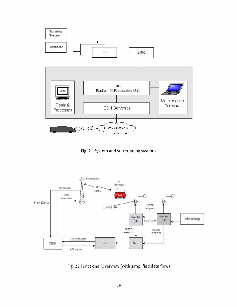
59
Fig. 21 System and surrounding systems
Fig. 22 Functional Overview (with simplified data flow)

60
3.2.1 Signal Manager RIU (SMR)
RIU
SMR
LEULEU
LEUConfiguration tools
Centralized
Diagnostic and
Maintenance
System
Configuration data
(Ethernet)SS 036 via “C”
interface
Diagnostic
events
SS 098
(Ethernet)
Power supplyDC
Up to 16
Fig. 23 SMR interfaces overview
The SMR HW elements are the following:
• Two Carrier Boards, hosting processing units, memories and GeminiX Cores;
• Two Power Supply boards;
• Up to 4 CIF Boards;
• One Backplane, interconnecting all the boards listed above;

61
3.2.2 Radio Infill Unit Processing Unit
The normal configuration of the RIU includes a dual processing unit. Hence the system is actively
redundant with one RIU online and one in standby, ready to immediately take over operation if
the online RIU halts. Moreover, the external communication channels are duplicated in the
normal configuration. The system is operated with only one RIU, but availability will be lower
without the possibility to switch RIU in case of failures. Each RIU is a 2-out-of-2 system, i.e. two
fail-safe processes perform the same task and they must agree on the result.
The RIU performs the functions in conjunction with other products and figure 24 gives a
schematic overview of the interconnections between the two RIU and their interfaces to external
systems. All the external systems are interfaced via adaptations, which handle any customer
specific solutions.
Fig. 24 Schematic diagram of the RIU and its external interfaces
3.2.3 Radio Infill Unit System Platform
The RIU is running the system software on a platform product that consists of three vital
computers (figure 25). The system platform provides support for detection of possible error
conditions, which might cause system malfunction. Using a combination of hardware and

62
system software error detection mechanisms, various errors can be effectively trapped in the
online RIU causing a switchover to the standby system.
The figure 25 shows the typical RIU cabinet with the system in dual configuration and with the
maximum of four ISDN Servers.
Fig. 25 Radio Infill Unit cabinet
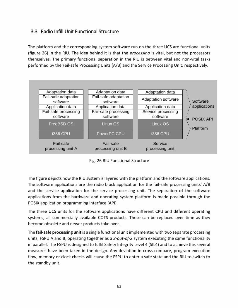
63
3.3 Radio Infill Unit Functional Structure
The platform and the corresponding system software run on the three UCS are functional units
(figure 26) in the RIU. The idea behind it is that the processing is vital, but not the processors
themselves. The primary functional separation in the RIU is between vital and non-vital tasks
performed by the Fail-safe Processing Units (A/B) and the Service Processing Unit, respectively.
i386 CPU
Adaptation dataFail-safe adaptation
software
Fail-safe processing
software
Fail-safe
processing unit A
FreeBSD OS
PowerPC CPU
Adaptation dataFail-safe adaptation
software
Fail-safe processing
software
Linux OS
i386 CPU
Service processing
software
Service
processing unit
Linux OS
Adaptation data
Platform
Software
applications
Fail-safe
processing unit B
Application data Application dataApplication data
POSIX API
Adaptation software
Fig. 26 RIU Functional Structure
The figure depicts how the RIU system is layered with the platform and the software applications.
The software applications are the radio block application for the fail-safe processing units’ A/B
and the service application for the service processing unit. The separation of the software
applications from the hardware and operating system platform is made possible through the
POSIX application programming interface (API).
The three UCS units for the software applications have different CPU and different operating
systems; all commercially available COTS products. These can be replaced over time as they
become obsolete and newer products take over.
The fail-safe processing unit is a single functional unit implemented with two separate processing
units, FSPU A and B, operating together as a 2-out-of-2 system executing the same functionality
in parallel. The FSPU is designed to fulfil Safety Integrity Level 4 (SIL4) and to achieve this several
measures have been taken in the design. Any deviation in cross-compare, program execution
flow, memory or clock checks will cause the FSPU to enter a safe state and the RIU to switch to
the standby unit.

64
The service processing unit performs service functions such as input/output from/to the external
units and systems. As seen in figure, it also interfaces the fail-safe processing units’ A and B,
distributing information received from, and receiving information to be sent to, the CTC/TMS,
the interlocking system and the ISDN Server(s). It is also responsible for loading executables in
the FSPU at start-up and to switch to the standby RIU in case of system failure in the online RIU.
The fail-safe adaptation software is the Generic Application that contains the operational rules
for a specific customer. It also contains the interface adaptations; e.g. for communication with
interlocking, CTC/TMS and other external systems as applicable.
The application data is the site data used by the Generic Product (e.g. infrastructure data and
other specific characteristics of the application) and it is part of the Generic Product.
The fail-safe processing software is the Generic Product that contains the core rules for
communicating with the ERTMS/ETCS Level 1 + Radio Infill Unit trains and the core of the radio
block logic. There is also a generic interface adaptation.
A key feature of this layered design is to facilitate the change of application data. If it becomes
necessary to change some data, e.g. if the site-specific layout is changed, the only change to the
software will be in the application data. The core system software and all hardware remain
unchanged.
Fig.27 SDM-MS Physical Architecture
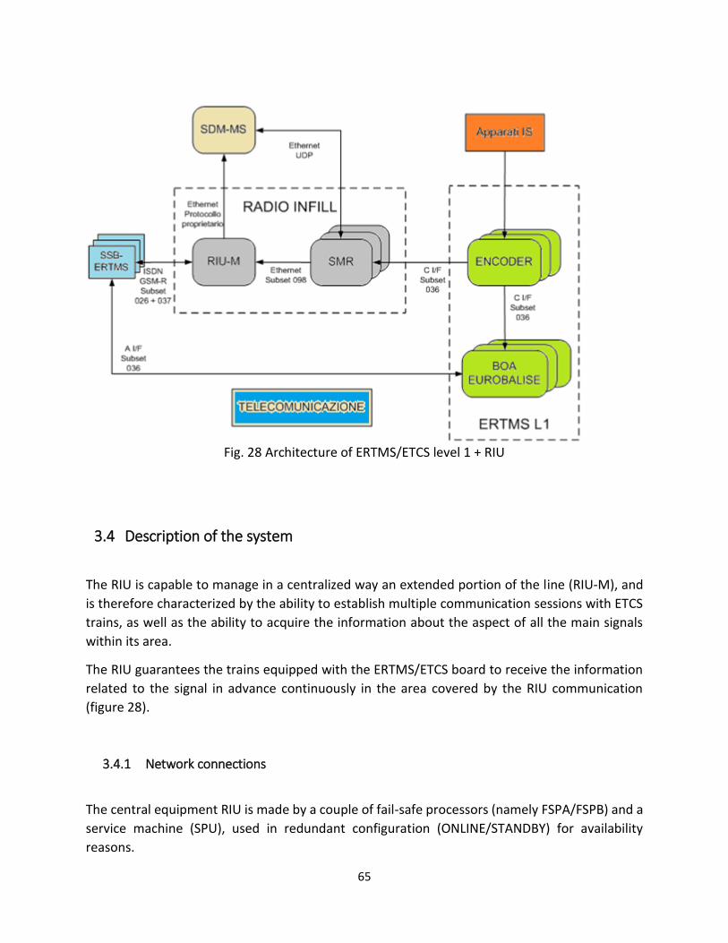
65
Fig. 28 Architecture of ERTMS/ETCS level 1 + RIU
3.4 Description of the system
The RIU is capable to manage in a centralized way an extended portion of the line (RIU-M), and
is therefore characterized by the ability to establish multiple communication sessions with ETCS
trains, as well as the ability to acquire the information about the aspect of all the main signals
within its area.
The RIU guarantees the trains equipped with the ERTMS/ETCS board to receive the information
related to the signal in advance continuously in the area covered by the RIU communication
(figure 28).
3.4.1 Network connections
The central equipment RIU is made by a couple of fail-safe processors (namely FSPA/FSPB) and a
service machine (SPU), used in redundant configuration (ONLINE/STANDBY) for availability
reasons.

66
The safety-related functions are executed on the FSPA/FSPB nodes, according to the safe
computing paradigm and an elaboration process based upon the diversity computation and
cross-check of the results.
The non-safety-related functions are executed on board of the service nodes SPU (C).
Besides, the service processor hosts Ethernet network connections used for communication with
the embedded systems SMR, as well as the connections with ISDN, Server devices for managing
communications toward the ETCS trains.
Each SMR device has a pair of Ethernet interfaces used for safety communication toward the RIU.
Furthermore, each SMR is connected to a pair of switches, each being part of an independent
dedicated optical fibre ring. This configuration allows the complete transmission of data, even in
case of failure of one of the switches.
The topology of the connections between the central equipment RIU and the remote devices
SMR embedded is shown in Figure 29.
SW2.1 SW2.2
SMR 1
SW2.3
x 4
F.O.1
F.O.1
F.O. Diag.
SWn.1 SWn.2
SMR N
SWn.3
X 4
SW1.1 SW1.2 SW1.3
x 4
F.O.2
F.O. Diag.
Vital Data
Non vital Data (diagnostic)
F.O.2
. . .RIU
Fig. 29 Diagram of the RIU-SMR safety network connection (with redundancy connection)

67
3.4.2 Telecommunication
The ERTMS/ETCS Level 1 + radio infill uses the GSM-R network for communication between RIU-
M and EVC and optic network / SDH fibre for communication between RIU-M and SMR.
The RIU-M, consists of two fail-safe units’ (online and standby processing) that are connected via
Ethernet to two SW.RIU-MP switches (O.F. primary vital network diagnostics and maintenance)
and SW.RIU-MS (O.F. network vital secondary and diagnostic and maintenance).
The ERTMS / ETCS Level 1 + SST radio infill telecommunications network architecture is shown in
Figure 30.
Fig. 30 Functional architecture of SST ERTMS/ETCS Levl1 + Radio Infill
3.5 Communication Protocol
The communication protocol between RIU and SMR allows the exchange of information in a safe
way, between the application layer running on the devices SMR and the corresponding level of
the RIU Adaptation.
Diag
x 2
SDH - Rete vitale primaria e diagnostica e manutenzione – Chiusura annello
F.O. Rete primaria e diagnostica
SW.RIU-M.S
F.O. Rete vitale secondaria
e diagnostica
SDH - Rete vitale secondaria e diagnostica e manutenzione – Chiusura anello
Diag
SW.1.P
SW.1.S
SW.n.P
SW.n.S
SMR nRIU-M
SW.RIU-M.P
SMR 1
ISDN PRI -E1
F.O. - Rete vitale primaria e diagnostica
F.O. - Rete vitale secondaria e diagnostica
Legenda
SDH - Rete vitale primaria e diagnostica – chiusura anelloSDH - Rete vitale secondaria e diagnostica – chiusura
anello)
Rame - Dati vitali (rete vitale primaria)
Rame - Dati non vitali (rete diagnostica)
Rame - Dati vitali (rete vitale secondaria)
Rame - ISDN
Bi-Dir F.O. 1
Bi-Dir F.O. 2
Gate
E1
Gate
E1
SFP rj45
Gigabit
SFP rj45
Gigabit
SFP rj45
GigabitSFP rj45
Gigabit
DiagDiag
x 2
ISDN PRI -E1
ISDN PRI -E1
ISDN PRI -E1
1
2
3
4
ADM
UCS_N
Diag
x 2
Diag
x 2Diag
Diag
SDM_RI
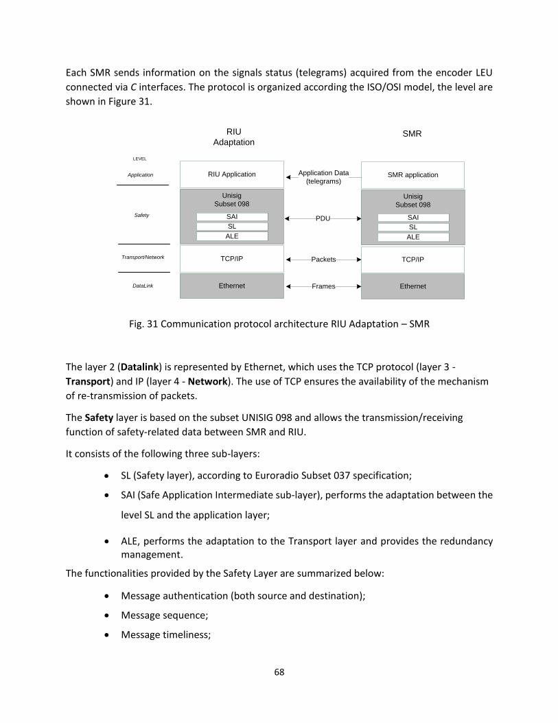
68
Each SMR sends information on the signals status (telegrams) acquired from the encoder LEU
connected via C interfaces. The protocol is organized according the ISO/OSI model, the level are
shown in Figure 31.
Unisig
Subset 098
TCP/IP
RIU
AdaptationSMR
Ethernet
TCP/IP
Ethernet
RIU Application SMR application
PDU
Packets
Application Data
(telegrams)
Frames
Application
Safety
Transport/Network
DataLink
LEVEL
SL
SAI
ALE
Unisig
Subset 098
SL
SAI
ALE
Fig. 31 Communication protocol architecture RIU Adaptation – SMR
The layer 2 (Datalink) is represented by Ethernet, which uses the TCP protocol (layer 3 -
Transport) and IP (layer 4 - Network). The use of TCP ensures the availability of the mechanism
of re-transmission of packets.
The Safety layer is based on the subset UNISIG 098 and allows the transmission/receiving
function of safety-related data between SMR and RIU.
It consists of the following three sub-layers:
• SL (Safety layer), according to Euroradio Subset 037 specification;
• SAI (Safe Application Intermediate sub-layer), performs the adaptation between the
level SL and the application layer;
• ALE, performs the adaptation to the Transport layer and provides the redundancy management.
The functionalities provided by the Safety Layer are summarized below:
• Message authentication (both source and destination);
• Message sequence;
• Message timeliness;
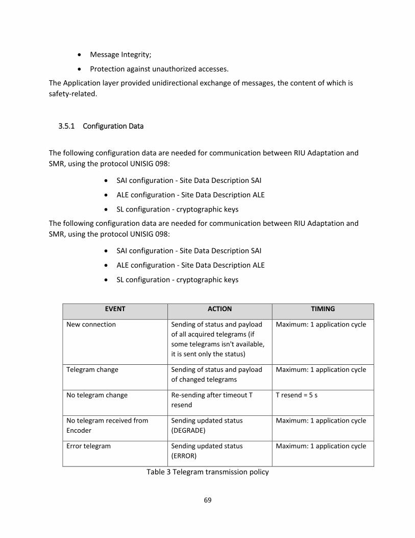
69
• Message Integrity;
• Protection against unauthorized accesses.
The Application layer provided unidirectional exchange of messages, the content of which is
safety-related.
3.5.1 Configuration Data
The following configuration data are needed for communication between RIU Adaptation and
SMR, using the protocol UNISIG 098:
• SAI configuration - Site Data Description SAI
• ALE configuration - Site Data Description ALE
• SL configuration - cryptographic keys
The following configuration data are needed for communication between RIU Adaptation and
SMR, using the protocol UNISIG 098:
• SAI configuration - Site Data Description SAI
• ALE configuration - Site Data Description ALE
• SL configuration - cryptographic keys
EVENT ACTION TIMING
New connection Sending of status and payload
of all acquired telegrams (if
some telegrams isn't available,
it is sent only the status)
Maximum: 1 application cycle
Telegram change Sending of status and payload
of changed telegrams
Maximum: 1 application cycle
No telegram change Re-sending after timeout T
resend
T resend = 5 s
No telegram received from
Encoder
Sending updated status
(DEGRADE)
Maximum: 1 application cycle
Error telegram Sending updated status
(ERROR)
Maximum: 1 application cycle
Table 3 Telegram transmission policy

70
Fig. 32 Data flow between train and wayside subsystems

71
3.5.2 Normal execution flow
During normal operation, the devices SMRs send to RIU the information acquired from LEU
through their interface IF/C.
Table 3 summarizes the conditions for sending data.
No feedback from the RIU is expected, in other words the communication at the application level
is mono-directional, as illustrated in Figure 32.
The management of transmission of information by the SMR is optimized to reduce the impact
on network bandwidth. This is particularly useful in situations where the level of data traffic
congestion is high.

72
Chapter 4
4 Test environment
Bombardier Italy is implemented a simulator that provides the possibility of running tests and operative scenarios for verification of interaction between wayside and onboard apparatuses and analysis of the functionality of the system ERTMS/ETCS L1 + Radio infill Unit. In this chapter is explained the architecture of the test environment.
4.1 Main target
The main purpose of developing test environment is to simulate different scenarios of running
test, analyzes of functional operation of wayside equipment in Level 1 + Radio Infill Unit and
interaction between RIU/ERTMS and Onboard equipment.
The main test environment operations are:
• Communication between EVC and The RIU (regulation based on Subset 037 and Subset
026 Baseline3);
• Selection of exiting telegrams from LEU;
• Setting speed and position of the train;
• Management of the telegrams from/to Balise, to/from train;
• Acquisition logs of different subsystems;
• Possibility to choose the track under test.
4.2 Architecture of the test environment
The test environment ERTMS/ETCS L1 + Radio Infill (figures 33, 34 and 35) consist of emulated,
simulated and real components:
• Simulated elements: refers to Software programs which are implemented (interface
part of the real subsystem);
• Emulated elements: refers to the Hardware/Software platform, which pretends to be
another device or program that other components expect to interact with;
• Real element: refers to the Hardware/Software platform target, which may also be the
subject of supply.
The combination of simulated, emulated and real elements enables to selectively and
effectively test the various components of the system.

73
The elements of test environment are grouped in the following groups:
• Informative Point (IP) ;
• Encoder ;
• SMR;
• RIU-M;
• EVC.
The elements which in the test environment are always emulated or simulated:
• IP (Informative Point)
• European Vital Computer (EVC)
The other components can be emulated, simulated or real.
Integration of different systems used in the test environment and the capacity of perform the
test effectively is obtained through:
• Interfacing modules (adapter) used for the exchange of information between the test
environment and the different elements (real, simulated or emulated), to drive the test;
• Checkpoints, through which it is possible to monitor the exchange of information
between the elements of the test object;
• User interface points, through which the test engineer can stimulate the test
environment.
Test Environment Manager
RIU
SMR
EncoderEncoderEncoderEVC
SMR
EncoderEncoderEncoder
SMR
EncoderEncoderEncoder
EVCEVC
Fig. 33 The test environment architecture
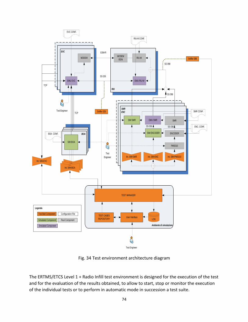
74
BALISEBALISE
BOABinario
SSBSSB
Binario
SMR
ENC
EVC
RIU
Ambiente di simulazione
TEST MANAGER
User InterfaceTEST CASES
REPOSITORY
EMU SMR
SS 036
ENCODER
SMR
SS 036
PMS010
EMU RIU-M
RIU-M
SS 098
SIM BOA
MODEM
ISDN MODEM
EMU EVC
LOG
SS 026
Sniffer 026
Sniffer 098
TCP
GSM-R
SS 098
ENC. CONF.
RIU-M CONF.
Configuration File
Legenda
Test Bed Component
Real ComponentSimulated Component
EVC CONF.
SMR CONF.
Int. SIM-SMR Int. SIM-ENC Int. SIM-PMS010
Int. SIM-BALISEInt. SIM-BALISEInt. SIM-BOA
Int. SIM-EVC
TCP
SIM ENCODER
Emulated Component
SIM SMR
Test Engineer
Test
Engineer
Test Engineer
BOA CONF.
Fig. 34 Test environment architecture diagram
The ERTMS/ETCS Level 1 + Radio Infill test environment is designed for the execution of the test
and for the evaluation of the results obtained, to allow to start, stop or monitor the execution
of the individual tests or to perform in automatic mode in succession a test suite.
75
The test environment ERTMS/ETCS Level 1 + Radio Infill is designed to manage simultaneously:
• A set of IP, Encoder and SMR, to obtain complex test scenarios;
• A set of EVC, to simulate the run of the ETCS train;
• A set of contiguous services to simulate the transition ETCS train between the
Development Plan.
4.3 Test environment description
The test environment of the ERTMS/ETCS Level 1 subsystem + Radio Infill is designed both for
the execution of tests to evaluation of the results obtained. This test environment configuration
provides the ability to start, stop or monitor the execution of the individual tests or
alternatively to run in automatic mode in succession a test suite.
The results expected in the various steps of the individual tests can be inserted within the test
environment, starting from a different source, from that which is used for the configuration of
the different elements that make up the test environment.
In the test environment are provided several "control points", through which it is possible to
monitor the execution of the test. The presence of such points makes it possible to monitor the
information that the various elements are exchanged, saving them in a structured format, to
simplify the analysis and reproduction of any problems.
In the test environment ERTMS/ETCS Level 1 + Radio Infill are provided two different test
execution modes:
• Interactive mode: the appropriately configured test environment is stimulated by the
test engineer; in this mode, it is possible to stimulate the test environment in a variety
of user interface points. The test result can be analyzed both during and on completion
of the test;
• Automatic mode: a single test or a test suite are defined, created in advance and
executed automatically; this mode provides the ability to perform a non-regression
analysis of the system.
The central part of the environment of the ground subsystem ERTMS/ETCS Level 1 + test radio
infill is composed of several modules, each with a specific functionality. The scheme is illustrated
in Figure 36.
The Test Cases Repository form in an organized manner collects individual test cases belonging
to different types of test you want to run.
Belonging to the different types of tests that you want to perform. The test run is carried out by
the Module Test Set Execution Manager, which recalling the appropriate functionality defined in
Test Execution Manager Module, automatically performs the various test cases selected by the
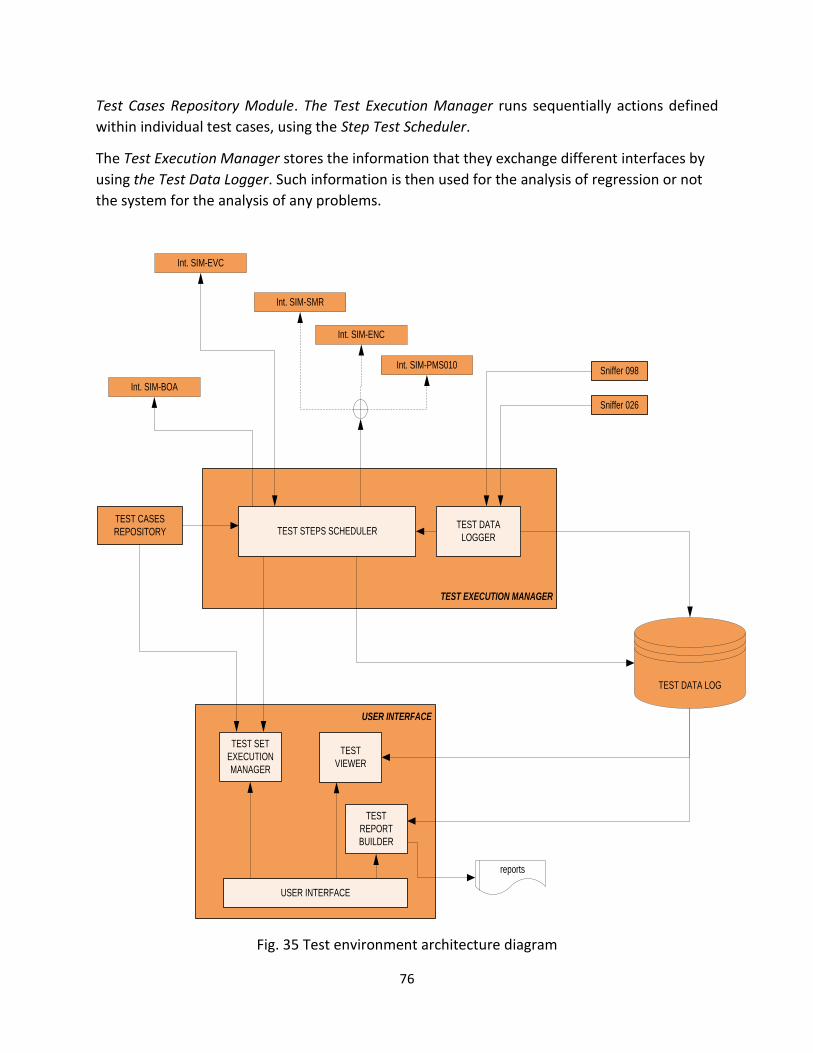
76
Test Cases Repository Module. The Test Execution Manager runs sequentially actions defined
within individual test cases, using the Step Test Scheduler.
The Test Execution Manager stores the information that they exchange different interfaces by
using the Test Data Logger. Such information is then used for the analysis of regression or not
the system for the analysis of any problems.
TEST EXECUTION MANAGER
USER INTERFACE
TEST CASES
REPOSITORY
TEST DATA LOG
TEST STEPS SCHEDULERTEST DATA
LOGGER
TEST SET
EXECUTION
MANAGER
TEST
VIEWER
TEST
REPORT
BUILDER
Sniffer 026
Sniffer 098
USER INTERFACE
Int. SIM-BOA
Int. SIM-PMS010
Int. SIM-ENC
Int. SIM-SMR
reports
Int. SIM-EVC
Fig. 35 Test environment architecture diagram
77
The modules Test Viewer and Test Report Builder are used for the analysis of the subsequent
tests and for the preparation of the documentation.
Signal Manager RIU (SMR)
The SMR consists of wayside equipment ERTMS/ETCS Level 1 + Radio used for picking the
telegrams from one or more Encoder, up to maximum 8 Encoders, the telegrams associated
Encoder extracting them from the message Eurobalises Subset 036 [12].
In addition, the SMR transmits the telegram to the RIU-M subsystem via Ethernet network and
protocol Subset 098 [12].
In the test environment, the SMR system interfaces with:
• The RIU, which receives the telegrams;
• One or more Encoders, up to 8 encoders via interface C, from which it takes the
information to be transmitted to the RIU-M;
• The test environment, from which it is possible, in the case where the SMR is present in
the simulated version, send the associated telegram Encoder that interfaces with the
SMR.
Every SMR is available up to 8 interface C, each of them can interface with a single Encoder. The
SMR in test environment can be utilized as an emulated or simulated element.
Encoder
The main task of the Encoder (figure 36) in the test environment is to select and send the
telegrams to SMR. Encoder selects the telegrams depending on signals input status.
In the test environment, the encoder interfaces with:
• The SMR, to which it sends the telegrams associated Encoder;
• The Adapter MS010, from which it receives the status of the 10 digital inputs;
• The telegram associated to Encoder, if the encoder is simulated.
In the test environment, the Encoder can be in emulated or real version. The encoder simulator
simulates the sending of telegrams SMR, simulating the functionality that the actual product is
performed by an FPGA connected to the interface C.

78
SMR
ENC
EMU SMR
SS 036
ENCODERS
SMR
SS 036
PMS010
ENC. CONF.
SMR CONF.
Int. SIM-SMR Int. SIM-ENC Int. SIM-PMS010
SIM ENCODERS
SIM SMR
Fig. 36 Functionality of the Encoder
In the test environment, it is possible to use the RIU in emulated or real version. The emulated
version refers to the implementation of the SW in execution on the different HW, different
from the HW / SW platform target (Desktop PC).
RIU-M
The RIU-M, within the ERTMS/ETCS Level 1 + SST Radio Infill, has the task of controlling the
running of the ETCS train on lines equipped with ERTMS/ETCS Level 1 + radio Infill (fig. 37),
through the exchange of radio messages belonging to subset 026 [4].
The RIU-M is characterized by the ability to simultaneously activate multiple communication
session with several EVC and acquire information about the track and the ETCS trains.
The RIU interfaces with European Vital Computer (EVC). The SMR acquires the telegrams received
from encoders.

79
SMR
ENC
SMR
ENC
EMU SMR SMRSIM SMR
SSB 1
RIU
SIM RIU
RIU
SS 098
MODEM
ISDN MODEM
EMU EVC
SS 026
Sniffer 026
Sniffer 098
GSM-R
RIU CONF.
SSB 2
MODEM
EMU EVC
SMR
ENC
EMU SMR SMR
SMR CONF.
SIM SMR
Fig. 37 RIU operating environment
EVC
The EVC implemented in the test environment as emulated element.
In the test environment, the EVC interfaces (figure 38) with:
• The RIU-m via implementation of SUBSET 098 [12];
• The Balise, acquirement of telegrams;
• The test environment, from which it is possible to simulate the controls, sending and
receiving of commands.
In the test environment, it is possible to simulate sending commands related to the
management of wayside subsystem to the emulated EVC.
To achieve this, aim the following interfaces are necessary:
• The bidirectional interface with the RIU-M;
• The one-way interface with the Balise;
• The bidirectional command and control interface (SIM-EVC).
The communication between with the RIU-M can be in two modalities:

80
• Emulated EVC with real GSM-R modem;
• Emulated EVC with simulated communication between EVC-RIU-M.
BALISEBALISE
BOA
SIM BOA
Int. SIM-BALISEInt. SIM-BALISE
Int. SIM-BALISE
BOA CONF.
SSBSSB
EVC
RIU
EMU RIU-M
RIU-MMODEM
ISDN MODEM
EMU EVC
SS 026
Sniffer 026
TCP
GSM-R
RIU-M CONF.
EVC CONF.
Int. SIM-EVC
TCP
Fig. 38 EVC operating environment
Eurobalise
The task of the Balise in the test environment is sending the Eurobalise messages to the EVC
(figure 39).

81
BALISEBALISE
BOA
SIM BOA
Int. SIM-BALISEInt. SIM-BALISEInt. SIM-BOA
BOA CONF.
SSBSSB
EVC
MODEM
EMU EVC
TCP
EVC CONF.
Int. SIM-EVC
TCP
Fig. 39 Balise functionality in test Environment
The Balise is always a simulated component in the test environment, implemented with the
functionality to simulate the telegrams at the request of EVC.
The sent messages are defined from configuration file generated for the real devices (Balise and
Encoders).
The test environment through SIM-Balise interface requires, if the location shown from EVC so
provides, the sending of a specific ETCS telegram to the train. So, the Balise module retrieves
configuration data from those relating to the required telegram and then transmit the EVC.
This module allows to simulate situations of corrupting degradation, especially the data
contained in the telegram.
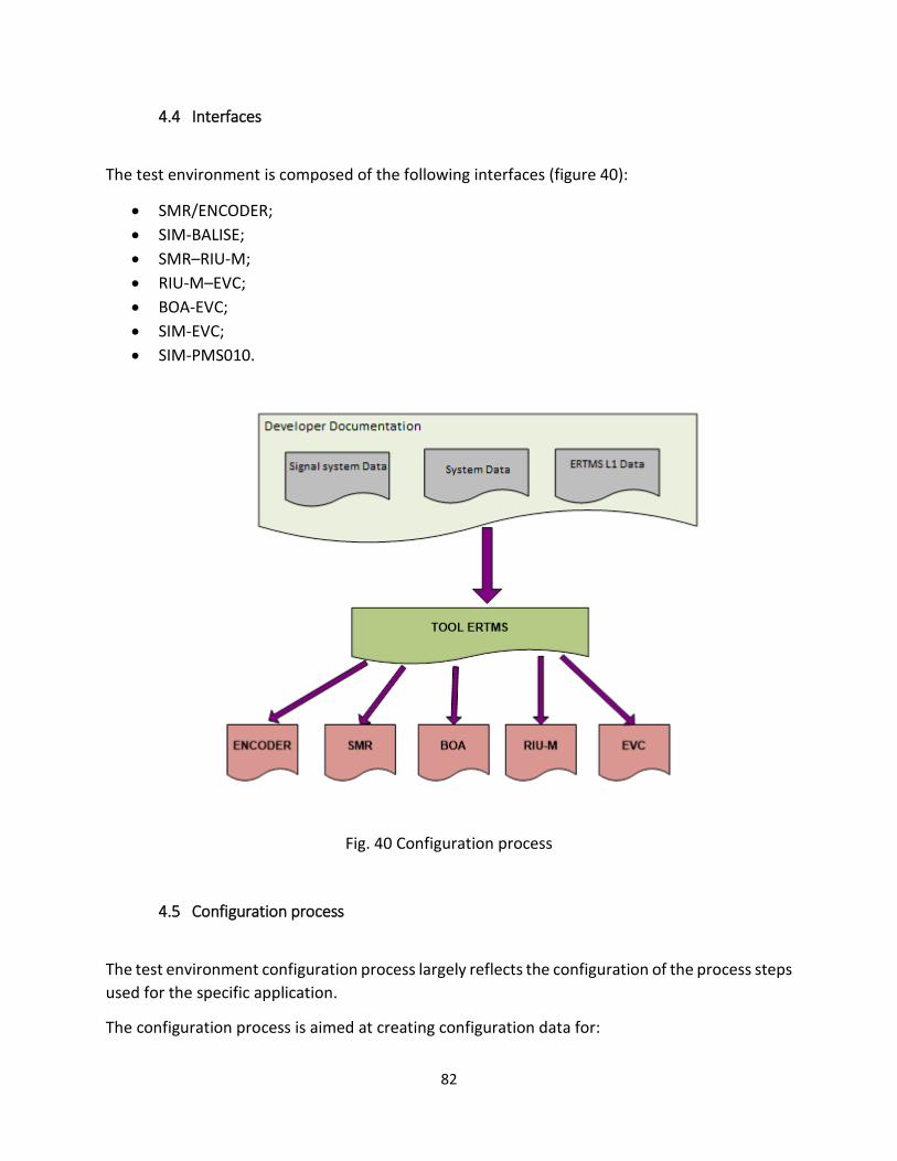
82
4.4 Interfaces
The test environment is composed of the following interfaces (figure 40):
• SMR/ENCODER;
• SIM-BALISE;
• SMR–RIU-M;
• RIU-M–EVC;
• BOA-EVC;
• SIM-EVC;
• SIM-PMS010.
Fig. 40 Configuration process
4.5 Configuration process
The test environment configuration process largely reflects the configuration of the process steps
used for the specific application.
The configuration process is aimed at creating configuration data for:

83
• SMR (SMR CON);
• Encoder (ENC CON);
• Moduli BOA (BOA CON);
• EVC (EVC CONF);
• RIU-M (RIU-M CONF).
The configuration process has been structured in three distinct operating phases:
• SMR/ENCODER/BOA configuration;
• RIU-M Configuration;
• EVC configuration.
4.6 Realization of Base Project
The main information contained in the realization of base project are the following:
• Signaling equipment (IS) Data:
• SCMT Data;
• ERTMS/ETCS L1 Data ;
• Radio Infill Data ;
• Equipment Data.
4.6.1 Test case Configuration:
They define the parameters that determine the operation of the individual elements involved.
For example, it defines the number of ETCS trains involved and the characteristics of individual
EVC trains.
Running test in automatic mode
The execution of the test in automatic mode let’s run a set of pre-defined test cases
automatically. In addition, the automatic mode allows the repetition of each specific test case,
because of change of some characteristic parameters, such as:
• Site Data, typically related to a specific station, used for the execution of test cases;
• Values of national parameters;
• Specific parameters of the train.
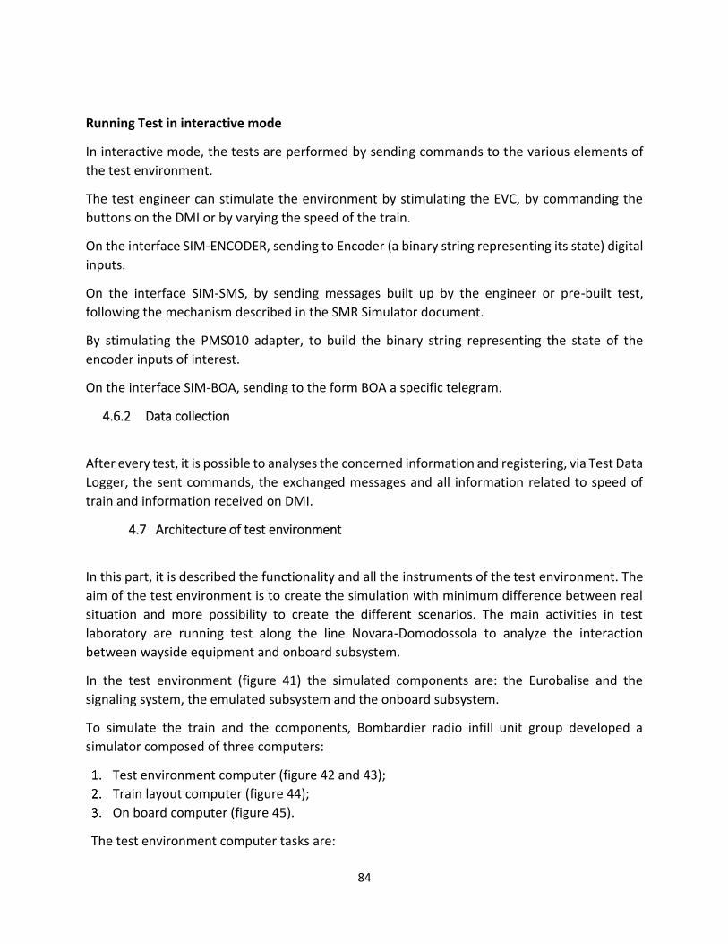
84
Running Test in interactive mode
In interactive mode, the tests are performed by sending commands to the various elements of
the test environment.
The test engineer can stimulate the environment by stimulating the EVC, by commanding the
buttons on the DMI or by varying the speed of the train.
On the interface SIM-ENCODER, sending to Encoder (a binary string representing its state) digital
inputs.
On the interface SIM-SMS, by sending messages built up by the engineer or pre-built test,
following the mechanism described in the SMR Simulator document.
By stimulating the PMS010 adapter, to build the binary string representing the state of the
encoder inputs of interest.
On the interface SIM-BOA, sending to the form BOA a specific telegram.
4.6.2 Data collection
After every test, it is possible to analyses the concerned information and registering, via Test Data
Logger, the sent commands, the exchanged messages and all information related to speed of
train and information received on DMI.
4.7 Architecture of test environment
In this part, it is described the functionality and all the instruments of the test environment. The
aim of the test environment is to create the simulation with minimum difference between real
situation and more possibility to create the different scenarios. The main activities in test
laboratory are running test along the line Novara-Domodossola to analyze the interaction
between wayside equipment and onboard subsystem.
In the test environment (figure 41) the simulated components are: the Eurobalise and the
signaling system, the emulated subsystem and the onboard subsystem.
To simulate the train and the components, Bombardier radio infill unit group developed a
simulator composed of three computers:
Test environment computer (figure 42 and 43);
Train layout computer (figure 44);
On board computer (figure 45).
The test environment computer tasks are:

85
• All configuration relating to the site information movement direction interfaces of the
board subsystem;
• Acquisition of the log simulation of BTM;
• Sending commands to the DMI;
• Sending the position of the train to the train layout computer;
• Execution of the test script;
• ISDN server to communicate with the RIU: test environment computer and RIU are
connected through Ethernet.
The train layout computer tasks are:
• Commands to signaling system simulator to change aspect of the signal;
• Positioning, choosing the direction of the train on the track.
The onboard computer tasks are:
• Receiving and sending Euroradio messages from/to the test environment;
• Collection and analysis of log JRU.
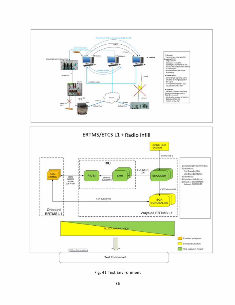
86
Fig. 41 Test Environment

87
Fig. 42 test environment computers in laboratory
Fig. 43 Configuration page on test environment computer

88
Fig. 44 Train layout computer
Fig. 45 onboard computer DMI
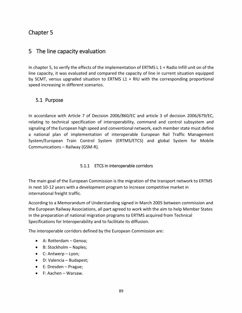
89
Chapter 5
5 The line capacity evaluation
In chapter 5, to verify the effects of the implementation of ERTMS L 1 + Radio Infill unit on of the line capacity, it was evaluated and compared the capacity of line in current situation equipped by SCMT, versus upgraded situation to ERTMS L1 + RIU with the corresponding proportional speed increasing in different scenarios.
5.1 Purpose
In accordance with Article 7 of Decision 2006/860/EC and article 3 of decision 2006/679/EC,
relating to technical specification of interoperability, command and control subsystem and
signaling of the European high speed and conventional network, each member state must define
a national plan of implementation of interoperable European Rail Traffic Management
System/European Train Control System (ERTMS/ETCS) and global System for Mobile
Communications – Railway (GSM-R).
5.1.1 ETCS in interoperable corridors
The main goal of the European Commission is the migration of the transport network to ERTMS
in next 10-12 years with a development program to increase competitive market in
international freight traffic.
According to a Memorandum of Understanding signed in March 2005 between commission and
the European Railway Associations, all part agreed to work with the aim to help Member States
in the preparation of national migration programs to ERTMS acquired from Technical
Specifications for Interoperability and to facilitate its diffusion.
The interoperable corridors defined by the European Commission are:
• A: Rotterdam – Genoa;
• B: Stockholm – Naples;
• C: Antwerp – Lyon;
• D: Valencia – Budapest;
• E: Dresden – Prague;
• F: Aachen – Warsaw.

90
Three of these corridors run across Italy.
For each corridor, it was made a deep study to select the most appropriate network to realise
such connection.
In this chapter, it is used an approach to capacity evaluation in the shape of compression
method, the approach is to calculate capacity consumption by compressing a timetable and
evaluate the number of possible train paths for the concerned line. It requires only data from
the timetable, therefore it can be applied without relevant obstacles.
5.2 The study case description
The Domodossola - Novara line is part of European Corridor A and will be the first worldwide trial
application for Radio Infill. It is a conventional line with 84 km single track, which is part of ERTMS
European Development Plan, included Domodossola cross border station Italy / Switzerland.
The line is equipped with Italian system Sistema Controllo Marcia Treno (SCMT), a discontinuous
train cab signalling system and it is going to be upgraded to continuous through ERTMS L1 + Radio
Infill Unit. The line is also equipped with relay stations and interlocking, axle counter along the
line, track circuits in stations and relay controlled level crossings.
In the following section, it is described the evaluation of the line capacity basing on detailed data
related to state of infrastructure and timetable, with trains split into three categories (A, B, C)
according to tolerable transversal acceleration.
5.3 The study Methodology
The approach to the evaluation of capacity for the railway networks is one of the most important
and delicate problems. Different railway environments represent different capacity needs and
this can easily lead to different interpretation and misunderstanding.
As an International standard, UIC (International Union of Railway) provides an approach to
capacity evaluation in UIC Leaflet 406, including guidelines for calculating capacity. The suggested
method is applicable to operated timetables on real infrastructures. The capacity calculation is
based on time-space area consumption obtained by compressing the timetable and evaluating
the number of possible train path for a line a node or a corridor including both them.
The method is called Compression Method and is applicable section by section.
In the present case study, the required data have been extracted by the document Fascicolo
Linea, issued by Rete Ferroviaria Italiana (RFI).

91
The line file (fig. 48) describes the following attributes: wayside equipment, braking degree,
allowed speed for different category of freight (A) and passengers (B) trains.
In figures 49-52 the full timetable related to the case study line is reported.
As earlier mentioned, the line is a single track one, with bidirectional traffic.
Fig. 46 Line File

92
Fig. 47 Timetable Domodossola Novara 06:00 – 12:00
Fig. 48 Timetable Domodossola Novara 12:00 – 18:00

93
Fig. 49 Timetable Domodossola Novara 18:00 – 00:00
Fig. 50 Timetable Domodossola Novara 00:00 – 06:00

94
As mentioned before, the scope is to evaluate the capacity consumption i.e. the utilization of
infrastructure’s physical attributes along a given section measured over a defined time (here 24
hour).
Starting from the real timetable, where the blue lines represent the freight trains and the black
ones the passengers’ trains, there are 32 trains per direction (from Novara to Domodossola and
vice versa).
To calculate the capacity consumption, it should be calculated at first the occupancy time of each
section in a defined time and then the additional times.
5.4 Calculation of capacity consumption
Occupation of infrastructure along the section in defied period (Capacity Consumption) is an
important factor to calculation of capacity and evaluation of performance of the line in railway
engineering. In this part to calculate capacity consumption is used the method proposed by UIC-
Leaflet 406 [15], [16], [17], [18].
5.4.1 Occupancy time
Capacity consumption is calculated by compressing all block sequences along the train paths within a defined timetable to the minimum headway. The resulted value, measured a timescale between first and last train paths after compressing the timetable.
5.4.2 Additional time
The calculated occupancy time is a time without buffer between compressed train paths.
Therefore, it must be added an additional time to have a secure specific level of service. In table
4 Proposed additional time rates due to specific situations (e.g. maintenance work, different
traffic density during the day) are calculated by UIC - Leaflet 406 [14].
Table 4 Proposed additional time rates

95
The additional time values used are intended to reflect the required quality of service.
The preferred solution for adding times is to insert them at the corresponding position in the
timetable (e.g. buffer times after every train path). Should this distribution of times not be
manageable, additional time must be considered collectively as a block.
The following criteria can be used for evaluating additional times resulting from:
• Buffer times to mitigate the impact of delays and to guarantee a desired level of service;
• Planned to shunt movements, coupling and uncoupling, crossing traffic (if not considered
in the compression process);
• Infrastructure maintenance.
•
5.4.3 Defined time period
Capacity may be analyzed over a longer period, even though compression of the timetable is
performed over a shorter "defined analyzing time". For example, it might be useful to analyses a
given timetable over a whole day, whereas capacity consumption is calculated for the peak
period only. Thus, the analyzed time may be 24 hours and the defined period (for calculation)
may be four hours only.
5.4.4 Capacity consumption
For capacity consumption values to best represent the corresponding infrastructure, the
following conditions can be used as a guideline:
• The capacity consumption values reflect the infrastructure characteristics of the defined
train path line sections;
• The line section with the highest capacity consumption value along the train path line
section is the representative line section for the train path line section;
• Acceptable quality of service is represented by capacity consumption up to 100%;
• Capacity consumption values beyond 100 % represent a bottleneck, which means a
lower quality of service and should be subject to timetable or infrastructure
improvements;
• Capacity consumption values below 100 % represent available capacity and thus the
potential for additional train paths along the defined train path line section.
The capacity consumption can be calculated as follows:

96
5.5 The Scenarios
To compare effect of European Rail Traffic Management System Level 1 + Radio Infill Unit (ERTMS
L1+RIU) against current state of line equipped by Italian national train control system, three
scenarios (0, 1 and 2) have been established.
Scenario 0: current situation of the Novara - Domodossola line in two directions (Reverse and
Nominal).
Scenario 1: the line is equipped with ERTMS L1 + RIU, a continuous radio block system that
provides continuous communication between train and trackside equipment; basing on this
assumption, it is possible to increase the speed of trains, in this scenario just the speed of
passengers’ trains.
Scenario 2: the line is equipped with ERTMS L1 + RIU, like for Scenario 1, but the speed is
increased both for passengers’ and freight trains.
5.5.1 Scenario 0
In scenario 0, as mentioned before, it is verified the current situation of the line equipped with
the Italian national control commanding system SCMT.
In figures 53 and 54 the values are the percentage of capacity consumption of each section
(higher values = more occupation).
As shown in the graphs, the most occupied section in Domodossola-Novara direction is the first
one, Domodossola - Villadossola with 31.2% occupation, as well as the less occupied is the
intermediate one Orta Miasino - Bolzano Novarese with 6.4% occupation.
In Novara-Domodossola direction, the most occupied section is Cuzzago– Premosello, with 32.2%
occupation in 24 hours, and the less occupied is the first one Novara-Vignale, with 3.7%
occupation of the line in the same period.
The total number of trains in both direction is equal to 63 trains 31 trains in direction Novara-
Domodossola and 32 trains in direction Domodossola-Novara and the capacity consumption is
beneath of 100 % a distinct amount of line section capacity is still available to use. The section
with highest capacity consumption is Domodossola-Villadossola with 31.2 % capacity
consumption and Curzzago-premosello 32.2 % assumed as the relevant value for the train path
line section.
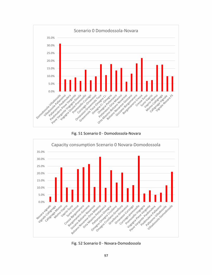
97
Fig. 51 Scenario 0 - Domodossola-Novara
Fig. 52 Scenario 0 - Novara-Domodossola
0.0%
5.0%
10.0%
15.0%
20.0%
25.0%
30.0%
35.0%
Scenario 0 Domodossola-Novara
0.0%
5.0%
10.0%
15.0%
20.0%
25.0%
30.0%
35.0%
Capacity consumption Scenario 0 Novara-Domodossola

98
5.5.2 Scenario 1
In scenario 1, it is assumed that the line is equipped with ERTMS L1 + RIU, therefore, there is
continuous communication between wayside equipment and the train, with the increase of
passengers’ trains speed in comparison with the current situation.
Figure 55 compares the scenarios 0 and 1, where is evident that in scenario 1, because of
increasing speed, occupancy time of the sections decreases as well as capacity consumption of
the section. the calculation is based on the method proposed by UIC-406 and respecting
obligations of PGOS [14] related to control commanding and signaling system and speed
restriction according the trains category.
In the opposite direction (Novara-Domodossola in figure 56) resulted the same behavior, which
allows more trains and rises the line capacity correspondingly.
In the direction, the capacity consumption is beneath of 100% a distinct amount of line section
capacity is still available to use. The section with highest capacity consumption is Domodossola-
Villadossola with 19.8% capacity consumption and Curzzago-premosello 29.9% assumed as the
relevant value for the train path line section.
In scenario 1 thanks to upgrading the system and subsequently increasing the speed of passenger
trains it is obtained a reduction of capacity consumption and against to scenario 0 consequently
22 additional trains in direction Domodossola-Novara and 5 additional trains in direction Novara-
Domodossola.

99
Fig. 53 Scenario 0 vs. Scenario 1 - Domodossola-Novara
Fig. 54 Scenario 0 vs. Scenario 1 - Novara-Domodossola
0.0%
5.0%
10.0%
15.0%
20.0%
25.0%
30.0%
35.0%
Dmodossola Novara Scenario 0 VS Senario 1
Scenario 0 Scenario 1
0.0%
5.0%
10.0%
15.0%
20.0%
25.0%
30.0%
35.0%
Novara Domodossola Scenario 0 VS Scenario 1
Capacity Consumption SCMT ‰ Capacity Consumption ‰ ERTMS L1+RIU
100
5.5.3 Scenario 2
In scenario 2, it is assumed that the line is upgraded from SCMT (Sistema Controllo Marcia) to
ERTMS L1 + RIU, therefore, the communication between train and the wayside equipment is
continuous and the train receives information relating to line state in advance by Radio Infill Unit
before arriving to the next Balise group so in this scenario, it is increased the speed of both
passenger and freight trains.
As explained before the calculation is based on the method proposed by UIC-406 and respecting
obligations of PGOS [14] related to control commanding and signaling system and speed
restriction according the trains category.
Travel time and occupancy time is consequently calculated for each section and compared with
scenarios 0 and 1 (figures 55 and 57).
In scenario 2 in both directions like scenario 0 and 1 obviously capacity consumption is beneath
of 100 % a distinct amount of line section capacity is still available to use. The section with highest
capacity consumption is Domodossola-Villadossola with 13% capacity consumption and
Curzzago-premosello 28.4% assumed as the relevant value for the train path line section.
thanks to upgrading the system and subsequently increasing the speed of passenger and freight
trains it is obtained a reduction of capacity consumption against to scenario 0 consequently 36
additional trains in direction Domodossola-Novara and 8 additional trains in direction Novara-
Domodossola.

101
Fig. 55 Comparison of capacity consumption Domodossola-Novara
Fig. 56 Comparison of capacity consumption Novara-Domodossola
0.0%
5.0%
10.0%
15.0%
20.0%
25.0%
30.0%
35.0%
Domodossola Novara Capacity Consumption
Scenario 0 Scenario 1 Scenario 2
0.0%
5.0%
10.0%
15.0%
20.0%
25.0%
30.0%
35.0%
Novara Domodossola Capacity Consumption
Scenario 0 Scenario 1 Scenario 2

102
Conclusions
In this thesis work, after the identification of the main goals of the ERTMS/ETCS and the
interoperability basing on documents issued by ERA, the focus is on the architecture of
ERTMS/ERTCS L 1 + RIU, again basing on documents provided by ERA and UNISIG.
It is explained the solution and the architecture of ERTMS/ERTCS L 1 + RIU proposed by
Bombardier Italy.
Key issues are the analysis of the interactions between trackside and onboard subsystems,
deployment of the running tests and simulation of different scenarios on the test environment
developed by bombardier Italy.
The case study is the verification of effects of upgrading the line Novara – Domodossola:
• From SCMT, Italian national train control system that involves continuous train
supervision of train movement but non-continuous communication between train and
trackside equipment;
• To ERTMS/ETCS L1 + Radio Infill Unit that provides continuous communication between
train board and trackside equipment.
Three 3 different scenarios have been built to evaluate capacity consumption of line in current
situation (SCMT in scenario 0) and after upgrading the line (to ERTMS/ETCS L1 + Radio Infill Unit
in scenario 1 and 2) basing on UIC 406 [14].
Thanks to the advantages of Radio Infill Unit, it is possible for the trains equipped by appropriate
boards and characteristic to run with higher speed, thereupon the train travel time decreases
and the section occupancy time decreases too.
Therefore, it is possible to run more trains in defined period of the time and to increase the total
capacity.
In scenario 0 (current situation, line equipped by SCMT) the average value of capacity
consumption for direction Domodossola-Novara is 10.7% and in the opposite direction Novara
Domodossola is 15.5%.
In scenario 1 (line equipped with ERTMS LEVEL 1 + RADIO Infill Unit and speed of passenger trains
are only increased, according to RFI document PGOS) the average value of capacity consumption
in direction Domodossola Novara is reduced to 9% and in opposite direction Novara
Domodossola to 13.4%.
In scenario 1 against to scenario 0 it is obtained 22 additional trains in direction Domodossola-
Novara and 5 additional trains in direction Novara-Domodossola.

103
In scenario 2 (line equipped with ERTMS LEVEL 1 + RADIO Infill Unit and speed increases for both
passenger and freight trains, according to RFI document PGOS) the average value of capacity
consumption in direction Domodossola Novara is further reduced to 7.7% and in opposite
direction Novara Domodossola to 11.9%. thanks to upgrading the system and subsequently
increasing the speed of passenger and freight trains it is obtained a reduction of capacity
consumption against to scenario 0 consequently 36 additional trains in direction Domodossola-
Novara and 8 additional trains in direction Novara-Domodossola.
The main goal to implement ERTMS/ETCS is interoperability and safety. Nevertheless, the study
demonstrates that, with the implementation of a continuous system, it would be possible to gain
additive benefits in terms of increased speed, decreasing travel time, higher capacity and
possibility running of more trains on the line.
104
References
[1] European Union – Directive (EU) 2016/797 of the European Parliament and of the Council of
11 May 2016 on the interoperability of the rail system within the European Union.
[2] European Commission - Directive 2008/57/EC on the interoperability of the rail system within
the Community (repealing Directives 96/48/EC and 2001/16/EC from 19 July 2010).
[3] European Commission - Directive 2001/16/EC of the European Parliament and of the council
of 19 March 2001on the interoperability of the trans-European conventional rail system.
[4] UNISIG - SUBSET 026 System Requirements Specification.
[5] CENELEC - EN 50126: Railway applications - The specification and Demonstration of Reliability,
Availability, Maintainability and Safety (RAMS).
[6] CENELEC - EN 50128: Railway applications - Communication, signaling and processing systems
Software for railway control and protection Systems.
[7] CENELEC - EN 50129: Railway applications - Communication, signaling and processing systems
- Safety related electronic systems for signaling.
[8] CENELEC - EN 50159-2: Railway applications - Communication, signaling and processing
systems - Safety related communication in open transmission systems.
[9] CENELEC – EN 50129: Railway applications - Communication, signaling and processing systems
- Safety related communication in open transmission systems safety related electronic system
for signaling.
[10] UNISIG - Subset 037 EuroRadio Functional Interface Specification (FIS).
[11] UNISIG - Subset 046 Radio In-Fill FFFS (Form Fit Functional Specification) - Version 2.0.0.
[12] UNISIG - Subset 036 FFFS (Form Fit Functional Specification) for Eurobalise.
[13] UNISIG - Subset 098 Safe Communication Interface.
[14] PGOS
[15] UIC - Leaflet 406.
[16] Capacity analysis of suburban rail networks
https://www.researchgate.net/publication/305479122
[17] Capacity versus punctuality assessment procedures and accessibility measures for rail networks

105
https://www.researchgate.net/publication/289965852_Capacity_versus_punctuality_assessment_procedures_and_accessibility_measures_for_rail_networks [18] Capacity measurement with the UIC 406 capacity method https://www.researchgate.net/publication/271427573_Capacity_measurement_with_the_UIC_406_capacity_method

106
Acronyms and Abbreviations
Acronym Description
API Application Programming Interface
ATCA Automatic Train Control
ATP Automatic Train Protection
BTM Balise Transmission Module
CBI Computer Based Interlocking
CCS Control command and signaling
CEN European Committee for Standardization
CENELEC Comité Européen de Normalisation Électrotechnique
CFM Communication Functional Module
COTS Commercial-Off-the-Shelf
CTC Centralized Traffic Control
DMI Driver Machin Interface
ERA European Railway Agency
ERTMS European Railway Traffic Management System
ETCS European Train Control System
ETML European Traffic Management Layer
EVC European Vital Computer
FIS Functional Interface Specification
GSM-R Global System for Mobile Communications – Railway
ISDN Integrated Services Digital Network
JRU Juridical Recording Unit
MAC Message Authentication Code
NSA National Safety Authorities
NTC National Train Control
OSJD Organization for Co-operation between Railways
OTIF Intergovernmental Organization for International Carriage by Rail
PGOS Prefazione generale all'orario di servizio
RBC Radio Block Center
RCS Rail Control System
RIU Radio Infill Unit
SA Source Address
SaPDU Safe Protocol Data Unit
SaSAP Safe Service Access Point
SCMT Sistema di Controllo Marcia Treno
SFM Safety Functional Module
SIL Safety Integrity Level
STM Specific Transmission Module

107
TAF Telematics Applications for Freight service
TAP Telematics Applications for Passengers service
TDPU Transport Protocol Data Unit
TDPU Transport Protocol Data Unit
TEN-T Trans-European Networks – Transport
TSIs Technical Specifications for Interoperability
UIC International Union of Railway