Factsheet no. 5: UPT Steel Structures Laboratory ... UPT Steel... · 500 mm, combining laced and...
6
Factsheet no. 5: UPT Steel Structures Laboratory, Timisoara, Romania Project summary Client: Politehnica University of Timisoara Architect: Arh. Mihai Mutiu Structural engineers: BRITT Ltd. Description of the existing building The building is located in Timisoara and it belongs to the Department of Steel Structures and Structural Mechanics from the Faculty of Civil Engineering of Timisoara. It is used as testing laboratory. The building was erected in 1959. The main structural system is composed of truss girders and columns. The walls are made from masonry combined with continuous glazed surfaces. In the longitudinal direction, X braces are provided in the last bay. The roof is made of timber boards (inner face), having lightweight thermal insulation and standing seam roof, being supported on truss purlins at a distance of 2.5 m. No bracing system exists in the roof level. The original drawings and design are not available, so all the dimensions were determined by in-situ measurements. The structure has 5 bays of 6 m (a total of 30 m length), the span of the transversal frame is of 10.5 m and the height of the structure is 7 m at the eaves and 7.55 m at the ridge, with a roof slope of 10%. Pictures 1 and 2 show some images during erection. Fig. 1. Picture of the Department of Steel Structures and Structural Mechanics (right) and the laboratory building (left) done in 1959
Transcript of Factsheet no. 5: UPT Steel Structures Laboratory ... UPT Steel... · 500 mm, combining laced and...
Factsheet no. 5: UPT Steel Structures Laboratory, Timisoara, Romania
Project summary
Client: Politehnica University of Timisoara Architect: Arh. Mihai Mutiu Structural engineers: BRITT Ltd.
Description of the existing building
The building is located in Timisoara and it belongs to the Department of Steel Structures and Structural Mechanics from the Faculty of Civil Engineering of Timisoara. It is used as testing laboratory. The building was erected in 1959. The main structural system is composed of truss girders and columns. The walls are made from masonry combined with continuous glazed surfaces. In the longitudinal direction, X braces are provided in the last bay. The roof is made of timber boards (inner face), having lightweight thermal insulation and standing seam roof, being supported on truss purlins at a distance of 2.5 m. No bracing system exists in the roof level. The original drawings and design are not available, so all the dimensions were determined by in-situ measurements. The structure has 5 bays of 6 m (a total of 30 m length), the span of the transversal frame is of 10.5 m and the height of the structure is 7 m at the eaves and 7.55 m at the ridge, with a roof slope of 10%. Pictures 1 and 2 show some images during erection.
Fig. 1. Picture of the Department of Steel Structures and Structural Mechanics (right)
and the laboratory building (left) done in 1959
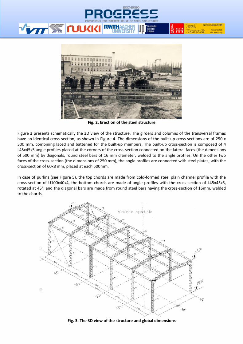
Fig. 2. Erection of the steel structure
Figure 3 presents schematically the 3D view of the structure. The girders and columns of the transversal frames have an identical cross-section, as shown in Figure 4. The dimensions of the built-up cross-sections are of 250 x 500 mm, combining laced and battened for the built-up members. The built-up cross-section is composed of 4 L45x45x5 angle profiles placed at the corners of the cross-section connected on the lateral faces (the dimensions of 500 mm) by diagonals, round steel bars of 16 mm diameter, welded to the angle profiles. On the other two faces of the cross-section (the dimensions of 250 mm), the angle profiles are connected with steel plates, with the cross-section of 60x8 mm, placed at each 500mm. In case of purlins (see Figure 5), the top chords are made from cold-formed steel plain channel profile with the cross-section of U100x40x4, the bottom chords are made of angle profiles with the cross-section of L45x45x5, rotated at 45°, and the diagonal bars are made from round steel bars having the cross-section of 16mm, welded to the chords.
Fig. 3. The 3D view of the structure and global dimensions
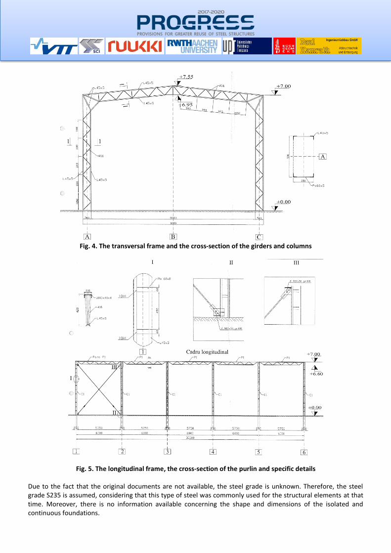
Fig. 4. The transversal frame and the cross-section of the girders and columns
Fig. 5. The longitudinal frame, the cross-section of the purlin and specific details
Due to the fact that the original documents are not available, the steel grade is unknown. Therefore, the steel grade S235 is assumed, considering that this type of steel was commonly used for the structural elements at that time. Moreover, there is no information available concerning the shape and dimensions of the isolated and continuous foundations.
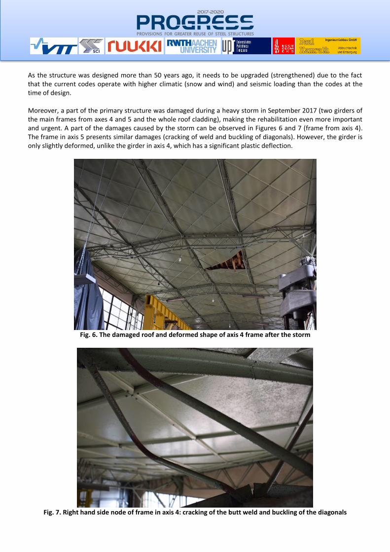
As the structure was designed more than 50 years ago, it needs to be upgraded (strengthened) due to the fact that the current codes operate with higher climatic (snow and wind) and seismic loading than the codes at the time of design. Moreover, a part of the primary structure was damaged during a heavy storm in September 2017 (two girders of the main frames from axes 4 and 5 and the whole roof cladding), making the rehabilitation even more important and urgent. A part of the damages caused by the storm can be observed in Figures 6 and 7 (frame from axis 4). The frame in axis 5 presents similar damages (cracking of weld and buckling of diagonals). However, the girder is only slightly deformed, unlike the girder in axis 4, which has a significant plastic deflection.
Fig. 6. The damaged roof and deformed shape of axis 4 frame after the storm
Fig. 7. Right hand side node of frame in axis 4: cracking of the butt weld and buckling of the diagonals
The structure is reused in-situ by keeping the same layout. With the exception of the damaged girders, the entire main and secondary structure is reused, with the addition of new elements mentioned above.
Design process
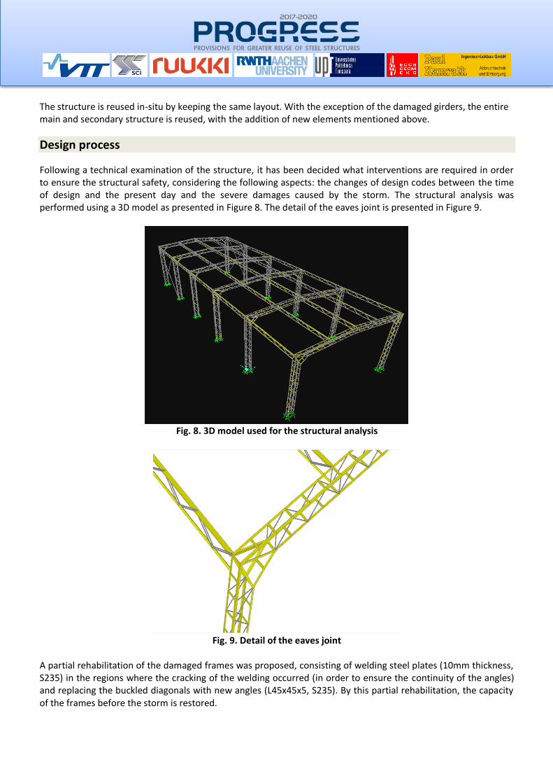
Following a technical examination of the structure, it has been decided what interventions are required in order to ensure the structural safety, considering the following aspects: the changes of design codes between the time of design and the present day and the severe damages caused by the storm. The structural analysis was performed using a 3D model as presented in Figure 8. The detail of the eaves joint is presented in Figure 9.
Fig. 8. 3D model used for the structural analysis
Fig. 9. Detail of the eaves joint
A partial rehabilitation of the damaged frames was proposed, consisting of welding steel plates (10mm thickness, S235) in the regions where the cracking of the welding occurred (in order to ensure the continuity of the angles) and replacing the buckled diagonals with new angles (L45x45x5, S235). By this partial rehabilitation, the capacity of the frames before the storm is restored.
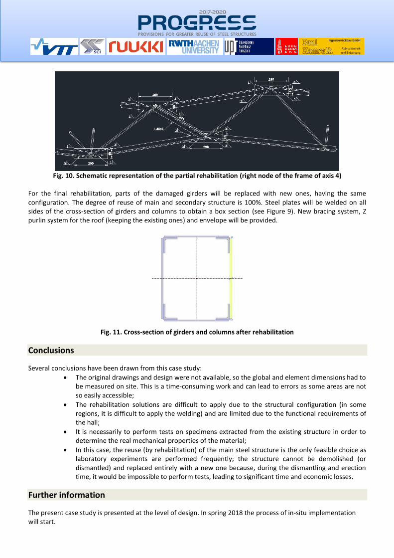
Fig. 10. Schematic representation of the partial rehabilitation (right node of the frame of axis 4)
For the final rehabilitation, parts of the damaged girders will be replaced with new ones, having the same configuration. The degree of reuse of main and secondary structure is 100%. Steel plates will be welded on all sides of the cross-section of girders and columns to obtain a box section (see Figure 9). New bracing system, Z purlin system for the roof (keeping the existing ones) and envelope will be provided.
Fig. 11. Cross-section of girders and columns after rehabilitation
Conclusions
Several conclusions have been drawn from this case study:
• The original drawings and design were not available, so the global and element dimensions had to be measured on site. This is a time-consuming work and can lead to errors as some areas are not so easily accessible;
• The rehabilitation solutions are difficult to apply due to the structural configuration (in some regions, it is difficult to apply the welding) and are limited due to the functional requirements of the hall;
• It is necessarily to perform tests on specimens extracted from the existing structure in order to determine the real mechanical properties of the material;
• In this case, the reuse (by rehabilitation) of the main steel structure is the only feasible choice as laboratory experiments are performed frequently; the structure cannot be demolished (or dismantled) and replaced entirely with a new one because, during the dismantling and erection time, it would be impossible to perform tests, leading to significant time and economic losses.
Further information
The present case study is presented at the level of design. In spring 2018 the process of in-situ implementation will start.


![Escorrentia - Upt[1]](https://static.fdocuments.us/doc/165x107/55721169497959fc0b8eeefe/escorrentia-upt1.jpg)