Factory Visit Report1 Composites Ahmedawad
15
1 Content: Page Content 1 About Factory 2 Product Range 3 Glass Fiber 3 Specification (Technical Standard) 3 Types of Glass Fiber 5 Control Testing & Qualification Testing 5 Manufacturing Process 7 Pipe Joining 8 Effects of fiberglass 15
-
Upload
ahmed-awad -
Category
Documents
-
view
20 -
download
7
description
Composites
Transcript of Factory Visit Report1 Composites Ahmedawad

1
Content:
Page
Content 1
About Factory 2
Product Range 3
Glass Fiber 3
Specification (Technical Standard) 3
Types of Glass Fiber 5
Control Testing & Qualification Testing 5
Manufacturing Process 7
Pipe Joining 8
Effects of fiberglass 15

2
Special thanks to Prof. Adel B. El-Shabasy and Ass. Prof. Dr. Hala Abd El Hakim for their cooperation with our team through guidance and providing necessary information regarding the visiting of the factory
About Factory:
Amiantit Fiberglass Egypt S.A.E. (AFEC) was established in 1998 as a closed joint stock company in Cairo, Egypt, manufacturing fiberglass pipes & accessories. It is engaged in manufacturing GRP pipes, tanks, manholes, fittings and accessories.
Figure 1: factory product
3
Product Range
AFEC Egypt Produces pipes with a diameter range up to 4000 mm. The manufactured standard pipe length is up to 12 m. Any other customized product for any application could also be designed and manufactured.
Growing awareness of the operational cost savings and superior corrosion resistance offered by glass reinforced plastic pipe made by AFEC will result in its widespread application for the following:
Water transmission and distribution Sanitary sewerage collection systems Storm water Effluent water Sea water intake and outfalls Irrigation Oil field injection piping Firefighting lines
Glass Fiber:
Glass in the form of fibers has found wide and varied applications in all kinds of industry because it is the most versatile industrial materials known today.
They exhibit useful bulk properties such as Hardness, Resistance to Chemical Attack, Stability, and Inertness, as well as Desirable Fiber Properties such as Strength, Flexibility, and Stiffness.
Specification (Technical Standard):
Engineers will often need to locate standards or specifications in the course of their work. A standard is a document
established by consensus and approved by a recognized body, that provides, for common and repeated use, rules, guidelines or characteristics for activities or their results, aimed at the achievement of the optimum degree of order in a given context (definition from the ISO/IEC Guide 2:2004).
4
Standards may be developed by a variety of groups, such as government agencies, technical or trade associations, professional societies or associations, or international or national organizations.
Standards Available: American Society for Testing & Materials (ASTM)
More than 12,000+ standards, covering metals, petroleum, construction, the environment, and more.
IEEE Xplore All current IEEE (Institute of Electrical and Electronics Engineers)
American National Standards Institute (ANSI) ANSI oversees the creation, promulgation and use of thousands of norms and guidelines that directly impact businesses in nearly every sector.
ADA Standards for Accessible Design Full formatted text and graphics, as published in the Code of Federal Regulations, complete with links to figures, graphics and cross-referenced sections.
ISO ISO International Standards ensure that products and services are safe, reliable and
of good quality. For business, they are strategic tools that reduce costs by minimizing waste and errors and increasing productivity. They help companies to access new markets, level the playing field for developing countries and facilitate free and fair global trade.
Classification of Standards
The standards produced by ASTM International fall into six categories: The Standard Specification, that defines the requirements to be satisfied by
subject of the standard. The Standard Test Method, that defines the way a test is performed and the
precision of the result. The result of the test may be used to assess compliance with a Standard Specification.
The Standard Practice, that defines a sequence of operations that, unlike a Standard Test Method, does not produce a result.
The Standard Guide, that provides an organized collection of information or series of options that does not recommend a specific course of action.
The Standard Classification, that provides an arrangement or division of materials, products, systems, or services into groups based on similar characteristics such as origin, composition, properties, or use.
The Terminology Standard, that provides agreed definitions of terms used in the other standards.

5
Types of Glass Fiber
As per ASTM CIE2 the glass fiber were classified according to the end use and chemical compositions.
E, Electrical low electrical conductivity
S, Strength high strength
C, Chemical high chemical durability m, modulus high stiffness
A, Alkali high alkali or soda lime glass
D, Dielectric low dielectric constant
Table 1: glass fiber types
Glass Fiber Forms:
(a) (b) (c) (d)
Figure 2: Glass Fiber Forms (a) Fibers (b) Roving (c) Mats (d) Chapped Strands
Performance Standards
Standards developed by BSI, EN, ISO, ASTM and AWWA are applied to a variety of fiber glass pipe applications including conveyance of sanitary sewage, water and industrial waste.
Control Testing & Qualification Testing
a. Raw Materials
Raw materials are delivered with vendor certification demonstrating their compliance with DPFC quality requirements. In addition, all raw materials are sample tested prior to their use. These tests ensure that the pipe materials comply with the specifications as stated.

6
b. Pipe Physical Properties
The manufactured pipe’s hoop and axial load strengths are verified on a routine basis. In addition, pipe construction and composition are confirmed.
(a) (b) (c)
Figure 3: testing machines (a) tension test (the same machine can be used to make bending test) (b) young's modulus testing (c) hoop tensile test
c. Finished Pipe All pipes are subjected to the following control checks:
■ Visual inspection ■ Wall thickness ■ Section Length ■ Diameter
d. Hydrostatic Design Basis Another important qualification test is the establishment of the Hydrostatic Design Basis - HDB. This test is carried out in accordance with ASTM D2992 Procedure B and requires hydrostatic pressure testing to failure (leakage) of many pipe samples at a variety of very high constant pressure levels.
Figure 4: d. Hydrostatic testing machine 100%

7
Manufacturing Process
Continuous Filament Winder: A continuous winder is composed of a continuous steel band supported by beams which form a cylindrically shaped mandrel. The beams rotate, friction pulls the band around and roller bearings allow the band to move longitudinally so that the entire mandrel continuously moves in a spiral path toward the end of the machine.
Figure 5: mandrel and steel band return unit
First, mould-release film, followed by various forms and patterns of glass fibers, embedded in a polyester resin matrix.
Inert filler can be interspersed within the structural laminate for some products. It is the continuous application of these materials onto the mandrel which forms the pipe.
After the pipe has been formed on the mandrel it is cured and later cut to required length.
Figure 6: Manufacturing process of glass fiber reinforcement pipe
Continuous winding process is considered as the most efficient, since once pipe production starts, as described above, the production process continues and would only stop at the completion of full order. This process is considered continuous since it does not hold and resume at the completion of each pipe or pipe layer.

8
Figure 7: winding process Machine
Pipe Joining
Joining pipes pipe sections are typically joined using GRP double bell couplings. Pipe and coupling will be supplied separately.
Other joining systems such as flanges, mechanical couplings and lay-up joints may also be used with GRP pipe.
Step 1: Clean Coupling Thoroughly clean double bell coupling grooves and rubber gasket rings to make sure no dirt or oil is present
Figure 8: Coupling cleaning
9
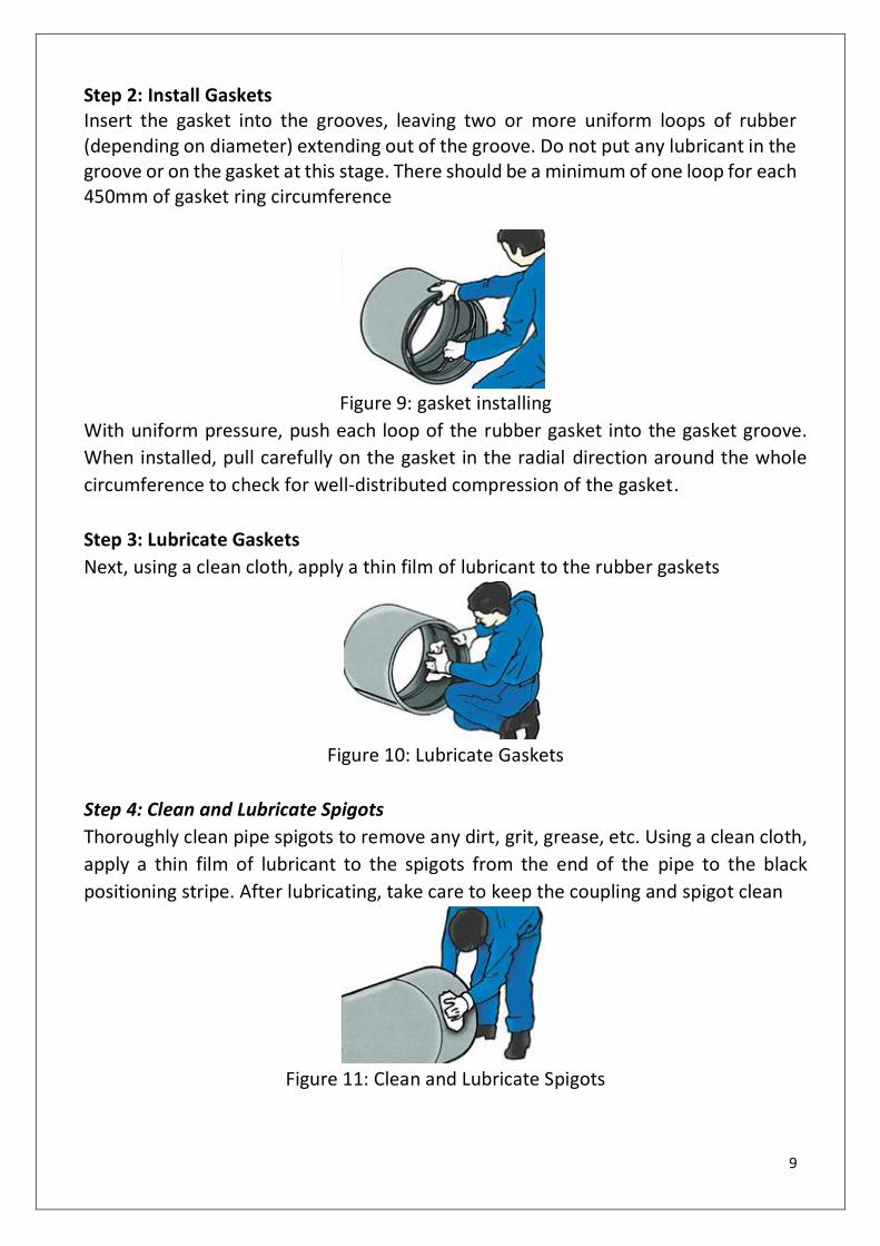
Step 2: Install Gaskets Insert the gasket into the grooves, leaving two or more uniform loops of rubber (depending on diameter) extending out of the groove. Do not put any lubricant in the groove or on the gasket at this stage. There should be a minimum of one loop for each 450mm of gasket ring circumference
Figure 9: gasket installing
With uniform pressure, push each loop of the rubber gasket into the gasket groove.
When installed, pull carefully on the gasket in the radial direction around the whole
circumference to check for well-distributed compression of the gasket.
Step 3: Lubricate Gaskets
Next, using a clean cloth, apply a thin film of lubricant to the rubber gaskets
Figure 10: Lubricate Gaskets
Step 4: Clean and Lubricate Spigots
Thoroughly clean pipe spigots to remove any dirt, grit, grease, etc. Using a clean cloth,
apply a thin film of lubricant to the spigots from the end of the pipe to the black
positioning stripe. After lubricating, take care to keep the coupling and spigot clean
Figure 11: Clean and Lubricate Spigots
10
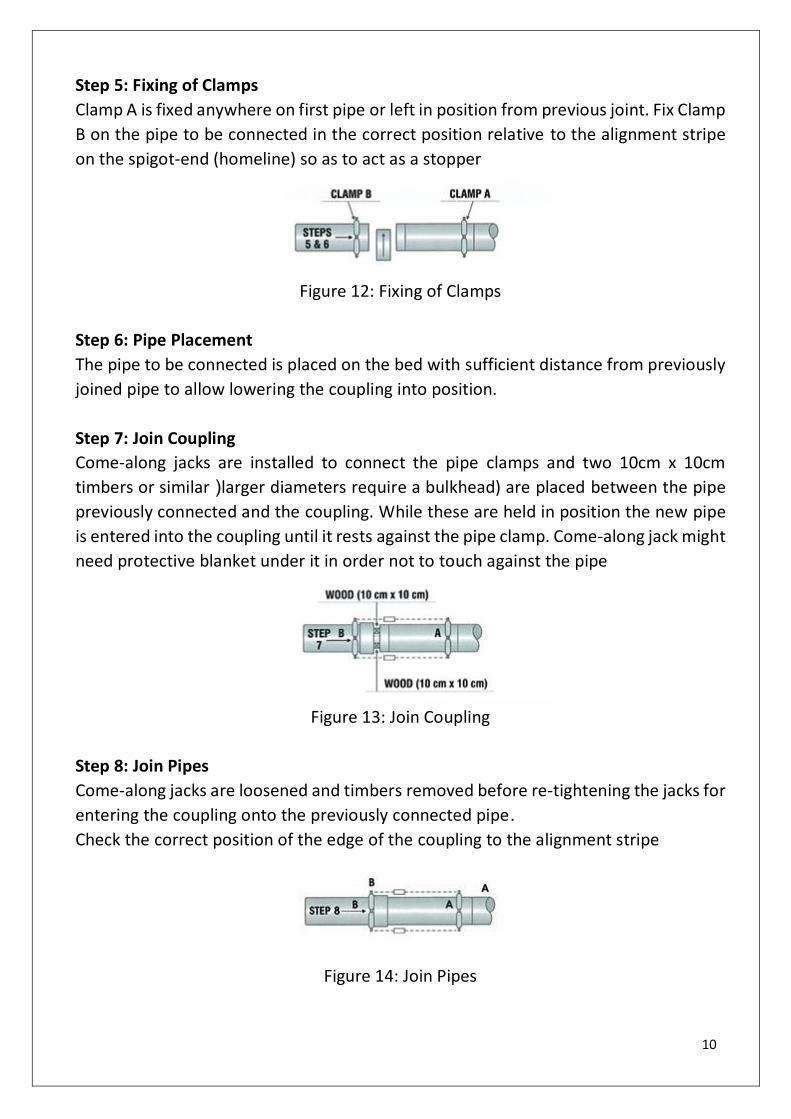
Step 5: Fixing of Clamps
Clamp A is fixed anywhere on first pipe or left in position from previous joint. Fix Clamp
B on the pipe to be connected in the correct position relative to the alignment stripe
on the spigot-end (homeline) so as to act as a stopper
Figure 12: Fixing of Clamps
Step 6: Pipe Placement
The pipe to be connected is placed on the bed with sufficient distance from previously
joined pipe to allow lowering the coupling into position.
Step 7: Join Coupling
Come-along jacks are installed to connect the pipe clamps and two 10cm x 10cm
timbers or similar (larger diameters require a bulkhead) are placed between the pipe
previously connected and the coupling. While these are held in position the new pipe
is entered into the coupling until it rests against the pipe clamp. Come-along jack might
need protective blanket under it in order not to touch against the pipe
Figure 13: Join Coupling
Step 8: Join Pipes
Come-along jacks are loosened and timbers removed before re-tightening the jacks for
entering the coupling onto the previously connected pipe.
Check the correct position of the edge of the coupling to the alignment stripe
Figure 14: Join Pipes

11
Other joining systems such as flanges, mechanical couplings and lay-up joints may also
be used with pipe.
Flanged Joints
GRP flanges should be joined according to the following procedure:
Figure 15: Flanged Joints
1. Thoroughly clean the flange face.
2. Ensure the gasket is clean and undamaged. Do not use defective gaskets.
3. Place the gasket in position, if necessary, with small strips of adhesive tape.
4. Align flanges to be joined.
5. Insert bolts, washers, and nuts. All hardware must be clean and lubricated to
avoid incorrect tightening. Washers must be used on all GRP flanges.
6. Using a torque wrench, tighten all bolts to 35 N.m (25 lb.ft) torque, following
standard flange bolt tightening sequences.
7. Repeat this procedure, raising the bolt torque to 70 N.m (50 lb.ft) or until the
flanges touch at their inside edges.
8. Check bolt torque one hour later and adjust if necessary.
Note: When connecting two GRP flanges, only one flange should have a gasket groove
in the face.
12
Other Joining Methods
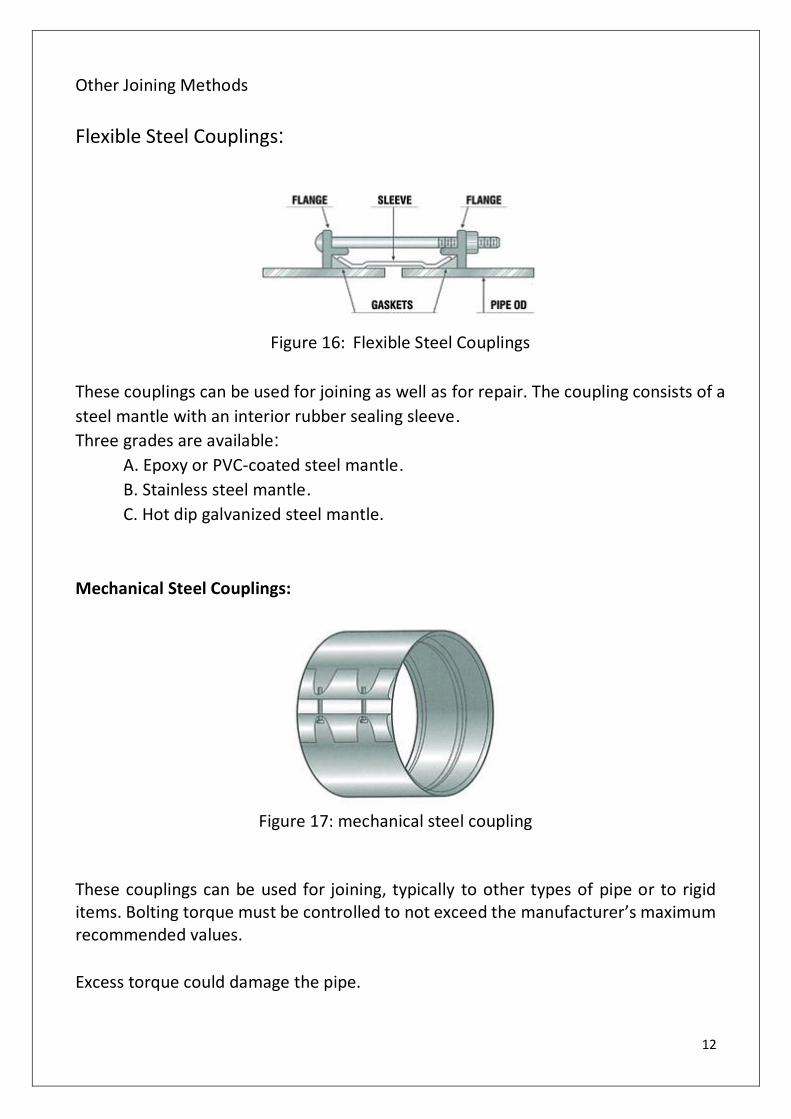
Flexible Steel Couplings:
Figure 16: Flexible Steel Couplings
These couplings can be used for joining as well as for repair. The coupling consists of a
steel mantle with an interior rubber sealing sleeve.
Three grades are available:
A. Epoxy or PVC-coated steel mantle.
B. Stainless steel mantle.
C. Hot dip galvanized steel mantle.
Mechanical Steel Couplings:
Figure 17: mechanical steel coupling
These couplings can be used for joining, typically to other types of pipe or to rigid items. Bolting torque must be controlled to not exceed the manufacturer’s maximum recommended values.
Excess torque could damage the pipe.

13
Figure 18: wide assortment of fittings, standard as well as non-standard.
Figure 19: Tee connection
14
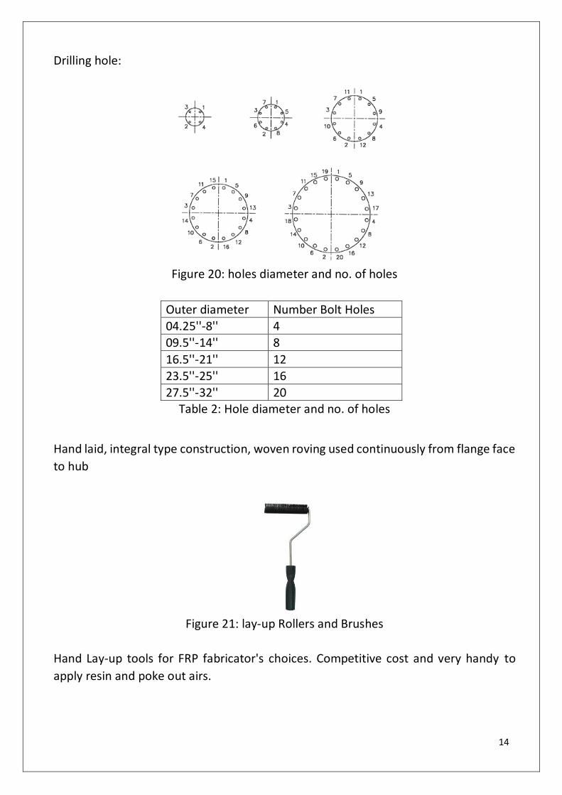
Drilling hole:
Figure 20: holes diameter and no. of holes
Outer diameter Number Bolt Holes
04.25''-8'' 4
09.5''-14'' 8
16.5''-21'' 12
23.5''-25'' 16
27.5''-32'' 20 Table 2: Hole diameter and no. of holes
Hand laid, integral type construction, woven roving used continuously from flange face
to hub
Figure 21: lay-up Rollers and Brushes
Hand Lay-up tools for FRP fabricator's choices. Competitive cost and very handy to
apply resin and poke out airs.

15
Effects of fiberglass
Working with fiberglass fibers and dust, without safe systems of work, can result in
irritation to the eyes, nose, throat and skin.
Safe working procedures
Employers must provide safe working procedures to minimize hazards. However, in
cramped or enclosed spaces where fiberglass insulation is generally installed, dust may
exceed recommended levels and may be difficult to control.
Dust mask should be worn. Protective overalls should be worn to avoid skin irritation,
and these should be washed regularly. Suitable gloves, tucked under overall cuffs, will
prevent hand irritation. Goggles should be worn.
Mandatory sign: means a sign requiring specific behavior
Figure 22: Mandatory sign