FACTORY AUTOMATION INVERTER FR-D700 · Precautions for Operation/Selection, ... Traverse function...
44
• Pursuing the easy operation • Long life and simple maintenance • Compact and space-saving • Supporting various applications INVERTER FR-D700 Global standard FACTORY AUTOMATION
Transcript of FACTORY AUTOMATION INVERTER FR-D700 · Precautions for Operation/Selection, ... Traverse function...

L(NA)06055ENG-H(1803)MEE
HEAD OFFICE: TOKYO BLDG., 2-7-3, MARUNOUCHI, CHIYODA-KU, TOKYO 100-8310, JAPAN
Mitsubishi Electric Corporation Nagoya Works is a factory certified for ISO14001 (standards for environmental management systems)and ISO9001(standards for quality assurance management systems)
• Pursuing the easy operation
• Long life and simple maintenance
• Compact and space-saving
• Supporting various applications
INVERTERFR-D700Global standard
FACTORY AUTOMATION

4
8
11
14
16
19
26
27
30
35
36
32
Features
Standard Specifications
Outline Dimension Drawings
Terminal Connection Diagram, Terminal Specification Explanation
Explanation of Operation Panel, Parameter Unit
Parameter List
Protective Functions
Options and peripheral devices
Precautions for Operation/Selection, Precautions for Peripheral Device Selection
FR-D700 Series Specification Difference List
Warranty, Inquiry
Global Player Contents
GLOBAL IMPACT OFMITSUBISHI ELECTRIC
We bring together the best minds to create the best technologies. At Mitsubishi Electric, we understand that technology is the driving force of change in our lives. By bringing greater comfort to daily life, maximiz-ing the efficiency of businesses and keeping things running across society, we integrate technology and innovation to bring changes for the better.
Mitsubishi Electric is involved in many areas including the following
Energy and Electric SystemsA wide range of power and electrical products from generators to large-scale displays.
Electronic DevicesA wide portfolio of cutting-edge semiconductor devices for systems and products.
Home ApplianceDependable consumer products like air conditioners and home entertain-ment systems.
Information and Communication SystemsCommercial and consumer-centric equipment, products and systems.
Industrial Automation SystemsMaximizing productivity and efficiency with cutting-edge automation technology.
Through Mitsubishi Electric’s vision, “Changes for the Better“ are possible for a brighter future.
•Features
•Standard specifications
•Outline dimension drawings
•Terminal connection diagram•Terminal specification explanation
•Operation panel•Parameter unit
•Parameter list
•Protective functions
•Option and peripheral devices
•Precautions for operation/selection•Precautions for peripheral device selection
•FR-D700 Series Specification Difference List
•Warranty•International FA Center
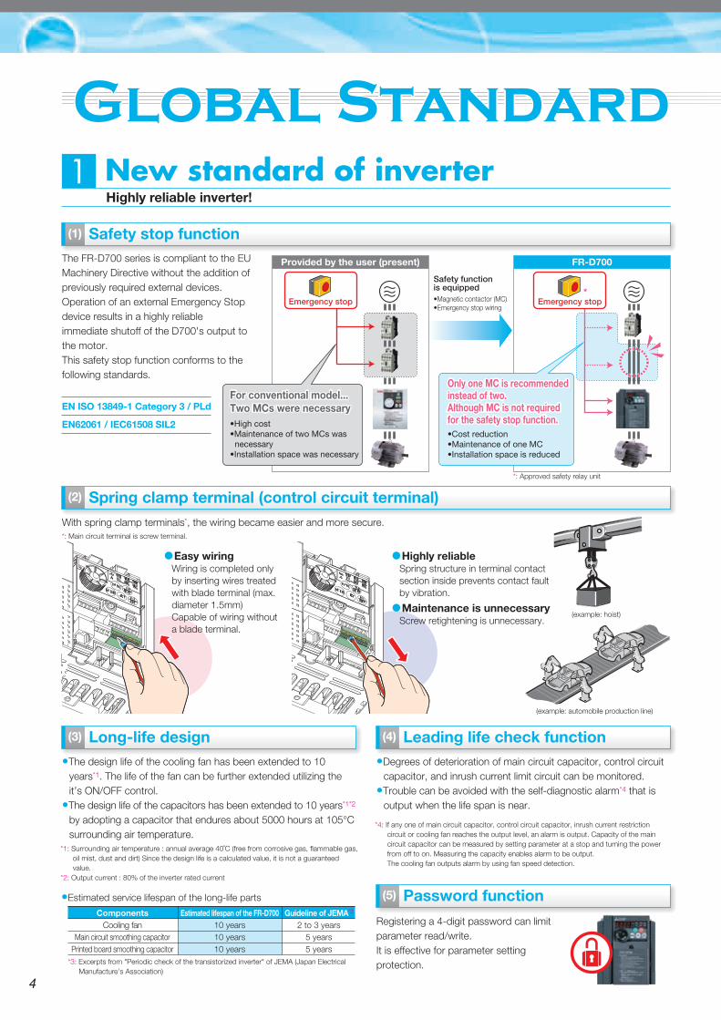
New standard of inverterHighly reliable inverter!
1
Safety stop function
Spring clamp terminal (control circuit terminal)
Long-life design
The FR-D700 series is compliant to the EU Machinery Directive without the addition of previously required external devices.Operation of an external Emergency Stop device results in a highly reliable immediate shutoff of the D700's output to the motor.This safety stop function conforms to the following standards.
Enhanced function
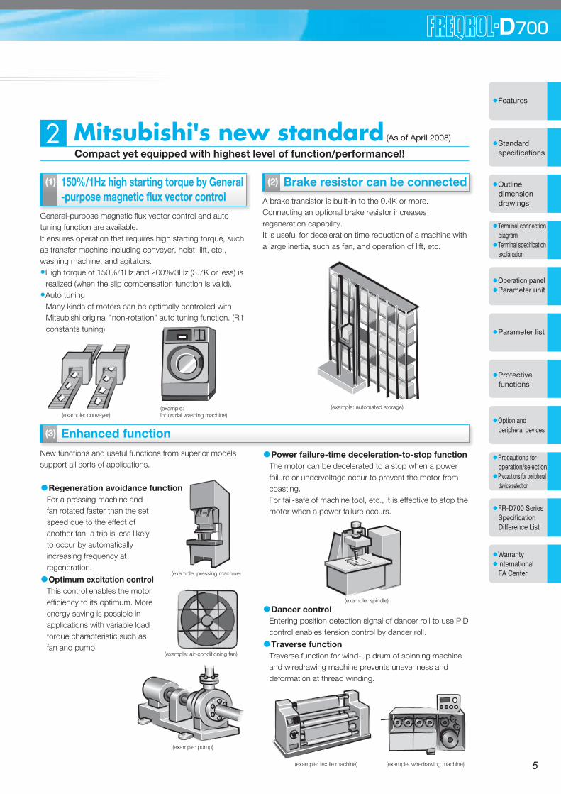
Mitsubishi's new standard (As of April 2008)
Compact yet equipped with highest level of function/performance!!2
150%/1Hz high starting torque by General-purpose magnetic flux vector control
General-purpose magnetic flux vector control and auto tuning function are available.It ensures operation that requires high starting torque, such as transfer machine including conveyer, hoist, lift, etc., washing machine, and agitators.•High torque of 150%/1Hz and 200%/3Hz (3.7K or less) is
realized (when the slip compensation function is valid).•Auto tuning
Many kinds of motors can be optimally controlled with Mitsubishi original "non-rotation" auto tuning function. (R1 constants tuning)
Brake resistor can be connectedA brake transistor is built-in to the 0.4K or more.Connecting an optional brake resistor increases regeneration capability.It is useful for deceleration time reduction of a machine with a large inertia, such as fan, and operation of lift, etc.
With spring clamp terminals*, the wiring became easier and more secure.
•The design life of the cooling fan has been extended to 10 years*1. The life of the fan can be further extended utilizing the it’s ON/OFF control.
•The design life of the capacitors has been extended to 10 years*1*2 by adopting a capacitor that endures about 5000 hours at 105°C surrounding air temperature.
Leading life check function•Degrees of deterioration of main circuit capacitor, control circuit
capacitor, and inrush current limit circuit can be monitored.•Trouble can be avoided with the self-diagnostic alarm*4 that is
output when the life span is near.
Password function
Registering a 4-digit password can limit parameter read/write.It is effective for parameter setting protection.
EN ISO 13849-1 Category 3 / PLd
EN62061 / IEC61508 SIL2
*: Main circuit terminal is screw terminal.
Provided by the user (present) FR-D700
Safety functionis equipped
Emergency stop
(example: automobile production line)
(example: hoist)
*1: Surrounding air temperature : annual average 40˚C (free from corrosive gas, flammable gas, oil mist, dust and dirt) Since the design life is a calculated value, it is not a guaranteed value.
*2: Output current : 80% of the inverter rated current
*3: Excerpts from "Periodic check of the transistorized inverter" of JEMA (Japan Electrical Manufacture's Association)
*4: If any one of main circuit capacitor, control circuit capacitor, inrush current restriction circuit or cooling fan reaches the output level, an alarm is output. Capacity of the main circuit capacitor can be measured by setting parameter at a stop and turning the power from off to on. Measuring the capacity enables alarm to be output.The cooling fan outputs alarm by using fan speed detection.
•Estimated service lifespan of the long-life parts
ComponentsCooling fan
Main circuit smoothing capacitorPrinted board smoothing capacitor
Estimated lifespan of the FR-D70010 years10 years10 years
Guideline of JEMA*3
2 to 3 years5 years5 years
Emergency stop
For conventional model...Two MCs were necessaryFor conventional model...Two MCs were necessary•High cost•Maintenance of two MCs was necessary•Installation space was necessary
•Magnetic contactor (MC)•Emergency stop wiring
(example: industrial washing machine)(example: conveyer)
(example: automated storage)
New functions and useful functions from superior models support all sorts of applications.
•Regeneration avoidance functionFor a pressing machine and fan rotated faster than the set speed due to the effect of another fan, a trip is less likely to occur by automatically increasing frequency at regeneration.
•Optimum excitation controlThis control enables the motor efficiency to its optimum. More energy saving is possible in applications with variable load torque characteristic such as fan and pump.
•Power failure-time deceleration-to-stop functionThe motor can be decelerated to a stop when a power failure or undervoltage occur to prevent the motor from coasting.For fail-safe of machine tool, etc., it is effective to stop the motor when a power failure occurs.
•Dancer controlEntering position detection signal of dancer roll to use PID control enables tension control by dancer roll.
•Traverse functionTraverse function for wind-up drum of spinning machine and wiredrawing machine prevents unevenness and deformation at thread winding.
(example: air-conditioning fan)
(example: pump)
(example: pressing machine)
(example: spindle)
(example: textile machine) (example: wiredrawing machine)
(1) (1)
(3)
(2)
(2)
(3) (4)
(5)
•Highly reliableSpring structure in terminal contact section inside prevents contact fault by vibration.
•Maintenance is unnecessaryScrew retightening is unnecessary.
•Easy wiringWiring is completed only by inserting wires treated with blade terminal (max. diameter 1.5mm)Capable of wiring without a blade terminal.
*: Approved safety relay unit
*
Only one MC is recommended instead of two.Although MC is not required for the safety stop function.
Only one MC is recommended instead of two.Although MC is not required for the safety stop function.•Cost reduction•Maintenance of one MC•Installation space is reduced
54
•Features
•Standard specifications
•Outline dimension drawings
•Terminal connection diagram•Terminal specification explanation
•Operation panel•Parameter unit
•Parameter list
•Protective functions
•Option and peripheral devices
•Precautions for operation/selection•Precautions for peripheral device selection
•FR-D700 Series Specification Difference List
•Warranty•International FA Center
New standard of inverterHighly reliable inverter!
1
Safety stop function
Spring clamp terminal (control circuit terminal)
Long-life design
The FR-D700 series is compliant to the EU Machinery Directive without the addition of previously required external devices.Operation of an external Emergency Stop device results in a highly reliable immediate shutoff of the D700's output to the motor.This safety stop function conforms to the following standards.
Enhanced function
Mitsubishi's new standard (As of April 2008)
Compact yet equipped with highest level of function/performance!!2
150%/1Hz high starting torque by General-purpose magnetic flux vector control
General-purpose magnetic flux vector control and auto tuning function are available.It ensures operation that requires high starting torque, such as transfer machine including conveyer, hoist, lift, etc., washing machine, and agitators.•High torque of 150%/1Hz and 200%/3Hz (3.7K or less) is
realized (when the slip compensation function is valid).•Auto tuning
Many kinds of motors can be optimally controlled with Mitsubishi original "non-rotation" auto tuning function. (R1 constants tuning)
Brake resistor can be connectedA brake transistor is built-in to the 0.4K or more.Connecting an optional brake resistor increases regeneration capability.It is useful for deceleration time reduction of a machine with a large inertia, such as fan, and operation of lift, etc.
With spring clamp terminals*, the wiring became easier and more secure.
•The design life of the cooling fan has been extended to 10 years*1. The life of the fan can be further extended utilizing the it’s ON/OFF control.
•The design life of the capacitors has been extended to 10 years*1*2 by adopting a capacitor that endures about 5000 hours at 105°C surrounding air temperature.
Leading life check function•Degrees of deterioration of main circuit capacitor, control circuit
capacitor, and inrush current limit circuit can be monitored.•Trouble can be avoided with the self-diagnostic alarm*4 that is
output when the life span is near.
Password function
Registering a 4-digit password can limit parameter read/write.It is effective for parameter setting protection.
EN ISO 13849-1 Category 3 / PLd
EN62061 / IEC61508 SIL2
*: Main circuit terminal is screw terminal.
Provided by the user (present) FR-D700
Safety functionis equipped
Emergency stop
(example: automobile production line)
(example: hoist)
*1: Surrounding air temperature : annual average 40˚C (free from corrosive gas, flammable gas, oil mist, dust and dirt) Since the design life is a calculated value, it is not a guaranteed value.
*2: Output current : 80% of the inverter rated current
*3: Excerpts from "Periodic check of the transistorized inverter" of JEMA (Japan Electrical Manufacture's Association)
*4: If any one of main circuit capacitor, control circuit capacitor, inrush current restriction circuit or cooling fan reaches the output level, an alarm is output. Capacity of the main circuit capacitor can be measured by setting parameter at a stop and turning the power from off to on. Measuring the capacity enables alarm to be output.The cooling fan outputs alarm by using fan speed detection.
•Estimated service lifespan of the long-life parts
ComponentsCooling fan
Main circuit smoothing capacitorPrinted board smoothing capacitor
Estimated lifespan of the FR-D70010 years10 years10 years
Guideline of JEMA*3
2 to 3 years5 years5 years
Emergency stop
For conventional model...Two MCs were necessaryFor conventional model...Two MCs were necessary•High cost•Maintenance of two MCs was necessary•Installation space was necessary
•Magnetic contactor (MC)•Emergency stop wiring
(example: industrial washing machine)(example: conveyer)
(example: automated storage)
New functions and useful functions from superior models support all sorts of applications.
•Regeneration avoidance functionFor a pressing machine and fan rotated faster than the set speed due to the effect of another fan, a trip is less likely to occur by automatically increasing frequency at regeneration.
•Optimum excitation controlThis control enables the motor efficiency to its optimum. More energy saving is possible in applications with variable load torque characteristic such as fan and pump.
•Power failure-time deceleration-to-stop functionThe motor can be decelerated to a stop when a power failure or undervoltage occur to prevent the motor from coasting.For fail-safe of machine tool, etc., it is effective to stop the motor when a power failure occurs.
•Dancer controlEntering position detection signal of dancer roll to use PID control enables tension control by dancer roll.
•Traverse functionTraverse function for wind-up drum of spinning machine and wiredrawing machine prevents unevenness and deformation at thread winding.
(example: air-conditioning fan)
(example: pump)
(example: pressing machine)
(example: spindle)
(example: textile machine) (example: wiredrawing machine)
(1) (1)
(3)
(2)
(2)
(3) (4)
(5)
•Highly reliableSpring structure in terminal contact section inside prevents contact fault by vibration.
•Maintenance is unnecessaryScrew retightening is unnecessary.
•Easy wiringWiring is completed only by inserting wires treated with blade terminal (max. diameter 1.5mm)Capable of wiring without a blade terminal.
*: Approved safety relay unit
*
Only one MC is recommended instead of two.Although MC is not required for the safety stop function.
Only one MC is recommended instead of two.Although MC is not required for the safety stop function.•Cost reduction•Maintenance of one MC•Installation space is reduced
54

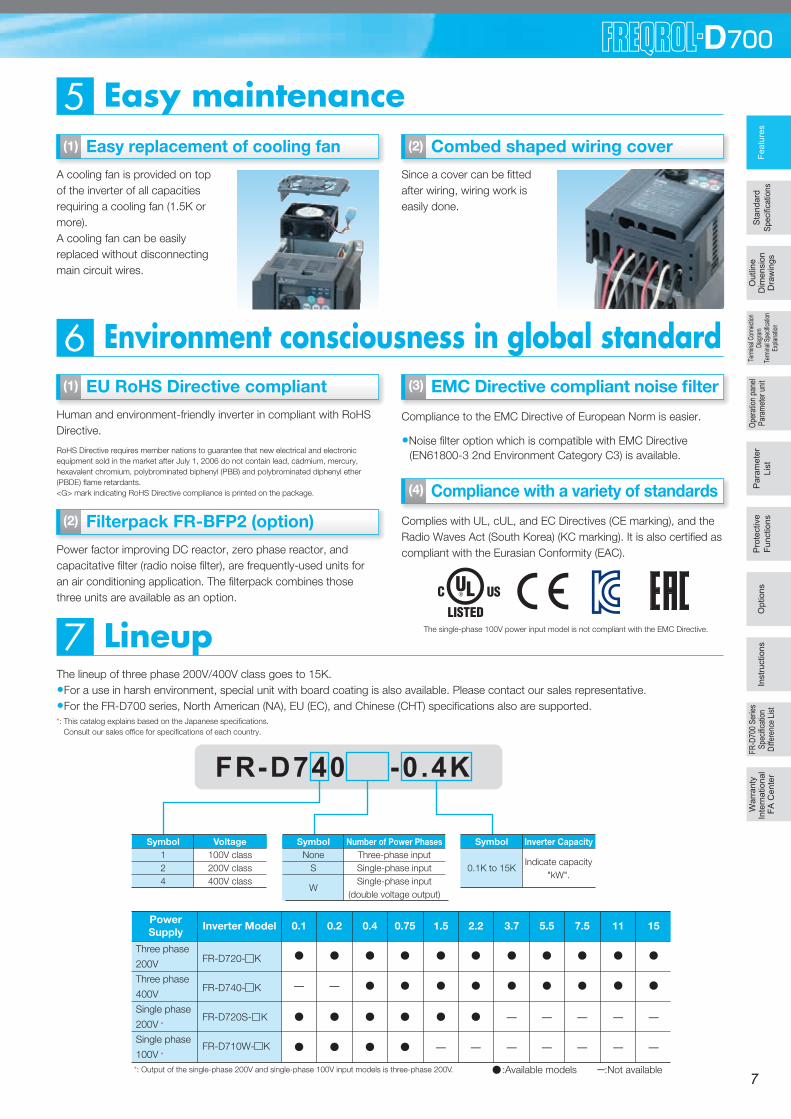
Environment consciousness in global standard 6EU RoHS Directive compliant
Easy use and time saving built-in as standard3
Human and environment-friendly inverter in compliant with RoHS Directive.
Compliance to the EMC Directive of European Norm is easier.
•Noise filter option which is compatible with EMC Directive (EN61800-3 2nd Environment Category C3) is available.
The lineup of three phase 200V/400V class goes to 15K.•For a use in harsh environment, special unit with board coating is also available. Please contact our sales representative. •For the FR-D700 series, North American (NA), EU (EC), and Chinese (CHT) specifications also are supported.
Parameter unit FR-PU07 (option)
An optional parameter unit (FR-PU07) can be connected as well.
Enhanced communication function• Mitsubishi inverter protocol and MODBUS®RTU
Communication speed of RS-485 has been improved (communication at 38.4kbps is available)"Multi command mode" has been added to Mitsubishi inverter protocol(data processing time of the inverter has been reduced to 1/4)Supports MODBUS®RTU
Easy setting from a personal computer using the FR Configurator (option)
Connecting a personal computer and the inverter via RS-485 communication enables setting with wizard (interactive) function of the FR Configurator (inverter setup software).In addition, a parameter setting can be converted from the FR-S500 series to the FR-D700 series by "Convert" function."Graph" function displays monitor data in waveform.
Enclosure surface operation panel FR-PA07 (option)
Optional enclosure surface operation panel (FR-PA07) can be connected. In addition, an operation panel for the FR-E500 series can be connected.
RoHS Directive requires member nations to guarantee that new electrical and electronic equipment sold in the market after July 1, 2006 do not contain lead, cadmium, mercury, hexavalent chromium, polybrominated biphenyl (PBB) and polybrominated diphenyl ether (PBDE) flame retardants.<G> mark indicating RoHS Directive compliance is printed on the package.
Compact and space saving4Easily replaceable compact body
Installation size is the same as that of the FR-S500 series which is the smallest model of the Mitsubishi inverter.
Side by side installation saves space
Space can be saved by side by side no clearance installation*.
Easy maintenance5Easy replacement of cooling fan
Lineup7
A cooling fan is provided on top of the inverter of all capacities requiring a cooling fan (1.5K or more).A cooling fan can be easily replaced without disconnecting main circuit wires.
Combed shaped wiring cover
Since a cover can be fitted after wiring, wiring work is easily done.
The operation panel of the inverter can not be removed. A parameter unit connection cable (FR-CB20 ) is separately necessary.
A parameter unit connection cable (FR-CB20 ) is separately necessary.
Quick setup with the setting dial
Setting dial is the feature of Mitsubishi inverters.•Displayed numbers can be jumped by turning the setting dial quickly, and numbers can
be changed one by one by turning it slowly, enabling speedy parameter setting.•The nonslip setting dial is easier to turn.
Acceleration/decelerationpattern setting
Acceleration/decelerationtime setting
Parameter list display
Setting wizard function (example: acceleration/deceleration time setting)
128mm
FR-D740-0.4K FR-S540E-0.4K
*: Use the inverter at the surrounding air temperature of 40˚C or less.
*: This catalog explains based on the Japanese specifications. Consult our sales office for specifications of each country.
FR-D740 -0.4K
Inverter Model 0.1 0.2 0.4 0.75 1.5 2.2 3.7 5.5 7.5
FR-D720- K
FR-D740- K
FR-D720S- K
FR-D710W- K
Three phase
200V
Three phase
400V
Single phase
200V *
Single phase
100V *
11 15
*: Output of the single-phase 200V and single-phase 100V input models is three-phase 200V. :Available models :Not available
PowerSupply
Symbol124
Voltage100V class200V class400V class
Symbol
0.1K to 15K
Inverter Capacity
Indicate capacity"kW".
SymbolNone
S
W
Number of Power PhasesThree-phase inputSingle-phase inputSingle-phase input
(double voltage output)
(1) (1) (2)
(1)
Filterpack FR-BFP2 (option)
Power factor improving DC reactor, zero phase reactor, and capacitative filter (radio noise filter), are frequently-used units for an air conditioning application. The filterpack combines those three units are available as an option.
(2)
(1) (2)
(2) (3)
EMC Directive compliant noise filter (3)
Complies with UL, cUL, and EC Directives (CE marking), and the Radio Waves Act (South Korea) (KC marking). It is also certified as compliant with the Eurasian Conformity (EAC).
Compliance with a variety of standards(4)
(4)
(5)
Feat
ures
Opt
ions
Sta
ndar
dSp
ecific
atio
ns
Oper
ation
pan
elPa
ram
eter
unit
Par
amet
erLi
stP
rote
ctiv
eFu
nctio
ns
Term
inal C
onne
ction
Diagra
mTe
rmina
l Spe
cifica
tion
Expla
natio
n
Out
line
Dim
ensi
onD
raw
ings
Inst
ruct
ions
FR-D
700
Serie
sSp
ecific
ation
Diffe
renc
e Lis
t
War
rant
yIn
tern
atio
nal
FA C
ente
r
•Setting such as direct input method with a numeric keypad, operation status indication, and help function are usable.Eight languages can be displayed.
•Parameter setting values of maximum of three inverters can be stored.
76
Introducing the Mitsubishi magnetic contactor
•Offers a selection of small frames
•Offers a line-up of safety contactors
•Supports small loads (auxiliary contact)
•Supports many international regulations as standardRefer to page 28for the selection.
The single-phase 100V power input model is not compliant with the EMC Directive.

8
Standard specifications
Three-phase 200V power supply
Three-phase 400V power supply
The applicable motor capacity indicated is the maximum capacity applicable for use of the Mitsubishi 4-pole standard motor.
The rated output capacity indicated assumes that the output voltage is 230V for three-phase 200V class and 440V for three-phase 400V class.
The % value of the overload current rating indicated is the ratio of the overload current to the inverter's rated output current. For repeated duty, allow time for
the inverter and motor to return to or below the temperatures under 100% load.
The maximum output voltage does not exceed the power supply voltage. The maximum output voltage can be changed within the setting range. However,
the pulse voltage value of the inverter output side voltage remains unchanged at about that of the power supply.
The braking torque indicated is a short-duration average torque (which varies with motor loss) when the motor alone is decelerated from 60Hz in the shortest
time and is not a continuous regenerative torque. When the motor is decelerated from the frequency higher than the base frequency, the average
deceleration torque will reduce. Since the inverter does not contain a brake resistor, use the optional brake resistor when regenerative energy is large. (The
option brake resistor cannot be used for 0.1K and 0.2K.) A brake unit (FR-BU2) may also be used.
The power supply capacity varies with the value of the power supply side inverter impedance (including those of the input reactor and cables).
Rating
Model FR-D720-K 0.1 0.2 0.4 0.75 1.5 2.2 3.7 5.5 7.5 11 15
Model FR-D720--NA 008 014 025 042 070 100 165 238 318 — —
Applicable motor capacity (kW) 0.1 0.2 0.4 0.75 1.5 2.2 3.7 5.5 7.5 11 15
Out
put
Rated capacity (kVA) 0.3 0.6 1.0 1.7 2.8 4.0 6.6 9.5 12.7 17.9 23.1
Rated current (A) 0.8 1.4 2.5 4.2 7.0 10.0 16.5 23.8 31.8 45.0 58.0
Overload current rating 150% 60s, 200% 0.5s (inverse-time characteristics)
Rated voltage Three-phase 200 to 240V
Regenerative braking torque 150% 100% 50% 20%
Pow
er s
uppl
y Rated input AC voltage/frequency Three-phase 200 to 240V 50Hz/60Hz
Permissible AC voltage
fluctuation170 to 264V 50Hz/60Hz
Permissible frequency fluctuation ±5%
Power supply capacity (kVA) 0.4 0.7 1.2 2.1 4.0 5.5 9.0 12.0 17.0 20.0 27.0
Protective structure (JEM1030) Enclosed type (IP20)
Cooling system Self-cooling Forced air cooling
Approximate mass (kg) 0.5 0.5 0.8 1.0 1.4 1.4 1.8 3.6 3.6 6.5 6.5
Model FR-D740-K 0.4 0.75 1.5 2.2 3.7 5.5 7.5 11 15
Model FR-D740--NA 012 022 036 050 080 120 160 — —
Model FR-D740-(SC)-EC 012 022 036 050 080 120 160 — —
Model FR-D740-K-CHT 0.4 0.75 1.5 2.2 3.7 5.5 7.5 — —
Applicable motor capacity (kW) 0.4 0.75 1.5 2.2 3.7 5.5 7.5 11 15
Out
put
Rated capacity (kVA) 0.9 1.7 2.7 3.8 6.1 9.1 12.2 17.5 22.5
Rated current (A) 1.2 2.2 3.6 5.0 8.0 12.0 16.0 23.0 29.5
Overload current rating 150% 60s, 200% 0.5s (inverse-time characteristics)
Rated voltage Three-phase 380 to 480V
Regenerative braking torque 100% 50% 20%
Pow
er s
uppl
y Rated input AC voltage/frequency Three-phase 380 to 480V 50Hz/60Hz
Permissible AC voltage fluctuation 325 to 528V 50Hz/60Hz
Permissible frequency fluctuation ±5%
Power supply capacity (kVA) 1.5 2.5 4.5 5.5 9.5 12.0 17.0 20.0 28.0
Protective structure (JEM1030) Enclosed type (IP20)
Cooling system Self-cooling Forced air cooling
Approximate mass (kg) 1.3 1.3 1.4 1.5 1.5 3.3 3.3 6.0 6.0
2
Fe
atu
res
Op
tio
ns
Sta
nd
ard
Speci
ficatio
ns
Pa
ram
ete
r
Lis
t
Pro
tective
Fu
nctio
ns
Term
inal
Con
nect
ion
Dia
gram
Term
inal
Spe
cific
atio
nEx
plan
atio
n
Ou
tlin
eD
ime
nsio
nD
raw
ing
sIn
str
uctio
ns
FR
-D70
0 S
erie
sS
peci
ficat
ion
Diff
eren
ce L
ist
Wa
rra
nty
Inte
rna
tio
na
l F
A C
en
ter
Ope
ratio
n pa
nel
Par
amet
er u
nit
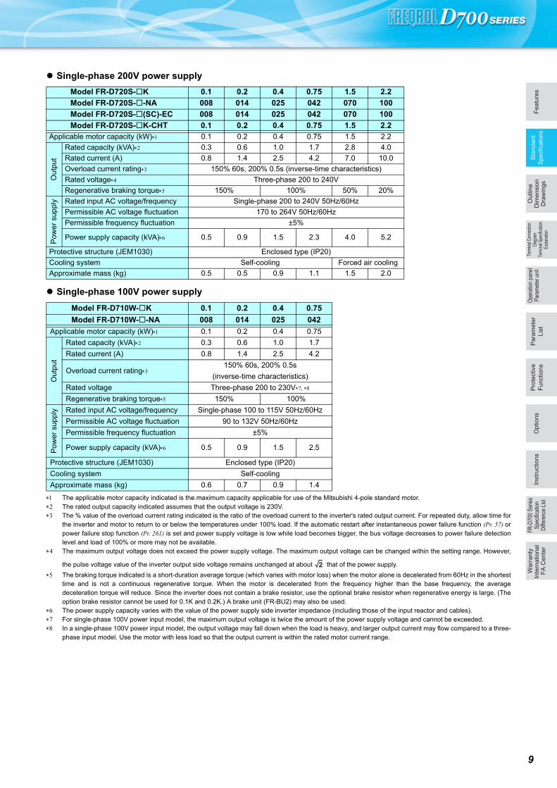
Single-phase 200V power supply
Single-phase 100V power supply
The applicable motor capacity indicated is the maximum capacity applicable for use of the Mitsubishi 4-pole standard motor. The rated output capacity indicated assumes that the output voltage is 230V. The % value of the overload current rating indicated is the ratio of the overload current to the inverter's rated output current. For repeated duty, allow time for
the inverter and motor to return to or below the temperatures under 100% load. If the automatic restart after instantaneous power failure function (Pr. 57) orpower failure stop function (Pr. 261) is set and power supply voltage is low while load becomes bigger, the bus voltage decreases to power failure detectionlevel and load of 100% or more may not be available.
The maximum output voltage does not exceed the power supply voltage. The maximum output voltage can be changed within the setting range. However,
the pulse voltage value of the inverter output side voltage remains unchanged at about that of the power supply.
The braking torque indicated is a short-duration average torque (which varies with motor loss) when the motor alone is decelerated from 60Hz in the shortesttime and is not a continuous regenerative torque. When the motor is decelerated from the frequency higher than the base frequency, the averagedeceleration torque will reduce. Since the inverter does not contain a brake resistor, use the optional brake resistor when regenerative energy is large. (Theoption brake resistor cannot be used for 0.1K and 0.2K.) A brake unit (FR-BU2) may also be used.
The power supply capacity varies with the value of the power supply side inverter impedance (including those of the input reactor and cables). For single-phase 100V power input model, the maximum output voltage is twice the amount of the power supply voltage and cannot be exceeded. In a single-phase 100V power input model, the output voltage may fall down when the load is heavy, and larger output current may flow compared to a three-
phase input model. Use the motor with less load so that the output current is within the rated motor current range.
Model FR-D720S-K 0.1 0.2 0.4 0.75 1.5 2.2
Model FR-D720S--NA 008 014 025 042 070 100
Model FR-D720S-(SC)-EC 008 014 025 042 070 100
Model FR-D720S-K-CHT 0.1 0.2 0.4 0.75 1.5 2.2Applicable motor capacity (kW) 0.1 0.2 0.4 0.75 1.5 2.2
Ou
tput
Rated capacity (kVA) 0.3 0.6 1.0 1.7 2.8 4.0
Rated current (A) 0.8 1.4 2.5 4.2 7.0 10.0
Overload current rating 150% 60s, 200% 0.5s (inverse-time characteristics)
Rated voltage Three-phase 200 to 240V
Regenerative braking torque 150% 100% 50% 20%
Pow
er s
uppl
y Rated input AC voltage/frequency Single-phase 200 to 240V 50Hz/60Hz
Permissible AC voltage fluctuation 170 to 264V 50Hz/60Hz
Permissible frequency fluctuation ±5%
Power supply capacity (kVA) 0.5 0.9 1.5 2.3 4.0 5.2
Protective structure (JEM1030) Enclosed type (IP20)
Cooling system Self-cooling Forced air cooling
Approximate mass (kg) 0.5 0.5 0.9 1.1 1.5 2.0
Model FR-D710W-K 0.1 0.2 0.4 0.75
Model FR-D710W--NA 008 014 025 042
Applicable motor capacity (kW) 0.1 0.2 0.4 0.75
Out
put
Rated capacity (kVA) 0.3 0.6 1.0 1.7
Rated current (A) 0.8 1.4 2.5 4.2
Overload current rating150% 60s, 200% 0.5s
(inverse-time characteristics)
Rated voltage Three-phase 200 to 230V
Regenerative braking torque 150% 100%
Po
wer
sup
ply Rated input AC voltage/frequency Single-phase 100 to 115V 50Hz/60Hz
Permissible AC voltage fluctuation 90 to 132V 50Hz/60Hz
Permissible frequency fluctuation ±5%
Power supply capacity (kVA) 0.5 0.9 1.5 2.5
Protective structure (JEM1030) Enclosed type (IP20)
Cooling system Self-cooling
Approximate mass (kg) 0.6 0.7 0.9 1.4
2
9
10
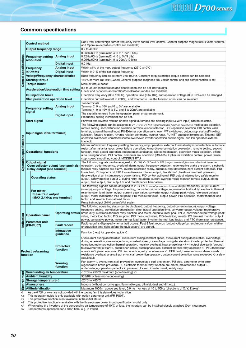
Common specifications
Co
ntr
ol s
pec
ific
atio
ns
Control method Soft-PWM control/high carrier frequency PWM control (V/F control, General-purpose magnetic flux vector control, and Optimum excitation control are available)
Output frequency range 0.2 to 400Hz
Frequency setting resolution
Analog input0.06Hz/60Hz (terminal2, 4: 0 to 10V/10 bits)0.12Hz/60Hz (terminal2, 4: 0 to 5V/9 bits)0.06Hz/60Hz (terminal4: 0 to 20mA/10 bits)
Digital input 0.01Hz
Frequency accuracy
Analog input Within 1% of the max. output frequency (25°C 10°C)
Digital input Within 0.01% of the set output frequency
Voltage/frequency characteristics Base frequency can be set from 0 to 400Hz. Constant-torque/variable torque pattern can be selected
Starting torque 150% or more (at 1Hz)...when General-purpose magnetic flux vector control and slip compensation is set
Torque boost Manual torque boost
Acceleration/deceleration time setting 0.1 to 3600s (acceleration and deceleration can be set individually), Linear and S-pattern acceleration/deceleration modes are available.
DC injection brake Operation frequency (0 to 120Hz), operation time (0 to 10s), and operation voltage (0 to 30%) can be changed
Stall prevention operation level Operation current level (0 to 200%), and whether to use the function or not can be selected
Op
erat
ion
sp
ecif
icat
ion
s
Frequency setting signal
Analog inputTwo terminalsTerminal 2: 0 to 10V and 0 to 5V are availableTerminal 4: 0 to 10V, 0 to 5V, and 4 to 20mA are available
Digital input The signal is entered from the operation panel or parameter unit.Frequency setting increment can be set.
Start signal Forward and reverse rotation or start signal automatic self-holding input (3-wire input) can be selected.
Input signal (five terminals)
The following signals can be assigned to Pr. 178 to Pr.182 (input terminal function selection): multi-speed selection, remote setting, second function selection, terminal 4 input selection, JOG operation selection, PID control valid terminal, external thermal input, PU-External operation switchover, V/F switchover, output stop, start self-holding selection, forward rotation, reverse rotation command, inverter reset, PU-NET operation switchover, External-NET operation switchover, command source switchover, inverter operation enable signal, and PU operation external interlock.
Operational functions
Maximum/minimum frequency setting, frequency jump operation, external thermal relay input selection, automatic restart after instantaneous power failure operation, forward/reverse rotation prevention, remote setting, second function, multi-speed operation, regeneration avoidance, slip compensation, operation mode selection, offline auto tuning function, PID control, computer link operation (RS-485), Optimum excitation control, power failure stop, speed smoothing control, MODBUS RTU
Output signalOpen collector output (two terminals)Relay output (one terminal)
The following signals can be assigned to Pr.190, Pr.192 and Pr.197 (output terminal function selection): inverter operation, up-to-frequency, overload alarm, output frequency detection, regenerative brake pre-alarm, electronic thermal relay function pre-alarm, inverter operation ready, output current detection, zero current detection, PID lower limit, PID upper limit, PID forward/reverse rotation output, fan alarm, heatsink overheat pre-alarm, deceleration at an instantaneous power failure, PID control activated, PID output interruption, safety monitor output, safety monitor output 2, during retry, life alarm, current average value monitor, remote output, alarm output, fault output, fault output 3, and maintenance timer alarm.
Operating status
For meterPulse train output(MAX 2.4kHz: one terminal)
The following signals can be assigned to Pr.54 FM terminal function selection: output frequency, output current (steady), output voltage, frequency setting, converter output voltage, regenerative brake duty, electronic thermal relay function load factor, output current peak value, converter output voltage peak value, reference voltage output, motor load factor, PID set point, PID measured value, output power, PID deviation, motor thermal load factor, and inverter thermal load factor.Pulse train output (1440 pulses/s/full scale)
Ind
icat
ion Operation panel
Parameter unit (FR-PU07)
Operating status
The following operating status can be displayed: output frequency, output current (steady), output voltage, frequency setting, cumulative energization time, actual operation time, converter output voltage, regenerative brake duty, electronic thermal relay function load factor, output current peak value, converter output voltage peak value, motor load factor, PID set point, PID measured value, PID deviation, inverter I/O terminal monitor, output power, cumulative power, motor thermal load factor, inverter thermal load factor, and PTC thermistor resistance.
Fault record Fault record is displayed when a fault occurs. Past 8 fault records (output voltage/current/frequency/cumulative energization time right before the fault occurs) are stored.
Interactive guidance Function (help) for operation guide
Protective/warning function
Protective function
Overcurrent during acceleration, overcurrent during constant speed, overcurrent during deceleration, overvoltage during acceleration, overvoltage during constant speed, overvoltage during deceleration, inverter protection thermal operation, motor protection thermal operation, heatsink overheat, input phase loss , output side earth (ground) fault overcurrent at start, output short circuit, output phase loss, external thermal relay operation , PTC thermistor operation, parameter error, PU disconnection, retry count excess , CPU fault, brake transistor alarm, inrush resistance overheat, analog input error, stall prevention operation, output current detection value exceeded , safety circuit fault
Warning function
Fan alarm, overcurrent stall prevention, overvoltage stall prevention, PU stop, parameter write error, regenerative brake pre-alarm , electronic thermal relay function pre-alarm, maintenance output , undervoltage, operation panel lock, password locked, inverter reset, safety stop
En
viro
nm
ent Surrounding air temperature -10°C to +50°C maximum (non-freezing)
Ambient humidity 90%RH or less (non-condensing)
Storage temperature -20°C to +65°C
Atmosphere Indoors (without corrosive gas, flammable gas, oil mist, dust and dirt etc.)
Altitude/vibration Maximum 1000m above sea level, 5.9m/s 2 or less at 10 to 55Hz (directions of X, Y, Z axes) As the 0.75K or lower are not provided with the cooling fan, this alarm does not function. This operation guide is only available with option parameter unit (FR-PU07). This protective function is not available in the initial status. This protective function is available with the three-phase power input specification model only. When using the inverters at the surrounding air temperature of 40°C or less, the inverters can be installed closely attached (0cm clearance). Temperatures applicable for a short time, e.g. in transit.
Fe
atu
res
Op
tio
ns
Sta
nd
ard
Speci
ficatio
ns
Pa
ram
ete
r
Lis
t
Pro
tective
Fu
nctio
ns
Term
inal
Con
nect
ion
Dia
gram
Term
inal
Spe
cific
atio
nEx
plan
atio
n
Ou
tlin
eD
ime
nsio
nD
raw
ing
sIn
str
uctio
ns
FR
-D70
0 S
erie
sS
peci
ficat
ion
Diff
eren
ce L
ist
Wa
rra
nty
Inte
rna
tio
na
l F
A C
en
ter
Ope
ratio
n pa
nel
Par
amet
er u
nit
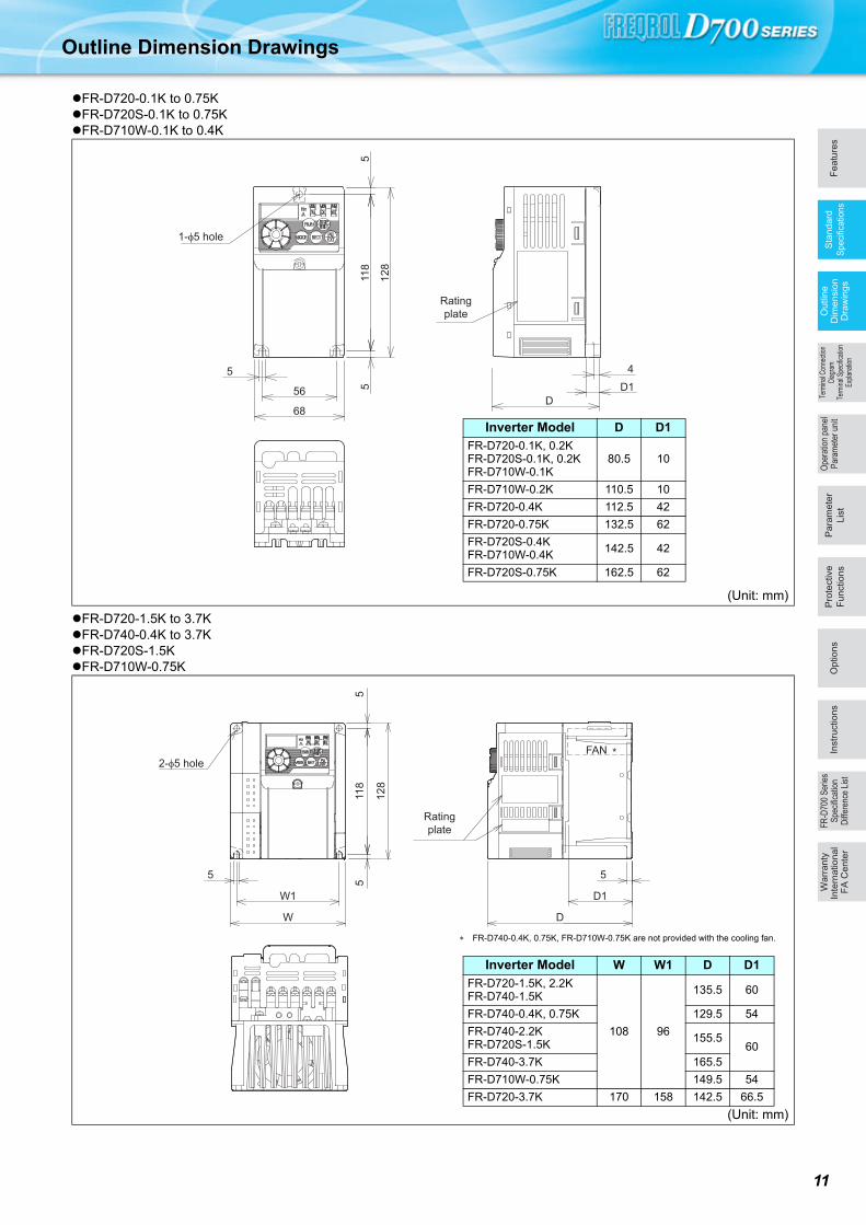
Outline Dimension Drawings
FR-D720-0.1K to 0.75KFR-D720S-0.1K to 0.75KFR-D710W-0.1K to 0.4K
FR-D720-1.5K to 3.7KFR-D740-0.4K to 3.7KFR-D720S-1.5KFR-D710W-0.75K
(Unit: mm)
(Unit: mm)
1-φ5 hole
5
68
56 511
85
12
8
Rating
plate
D
4
D1
Inverter Model D D1
FR-D720-0.1K, 0.2KFR-D720S-0.1K, 0.2KFR-D710W-0.1K
80.5 10
FR-D710W-0.2K 110.5 10
FR-D720-0.4K 112.5 42
FR-D720-0.75K 132.5 62
FR-D720S-0.4KFR-D710W-0.4K
142.5 42
FR-D720S-0.75K 162.5 62
Rating
plate
2-φ5 hole*FAN
5
W1
W
55
12
8
11
8
5
D1
D
FR-D740-0.4K, 0.75K, FR-D710W-0.75K are not provided with the cooling fan.
Inverter Model W W1 D D1
FR-D720-1.5K, 2.2KFR-D740-1.5K
108 96
135.5 60
FR-D740-0.4K, 0.75K 129.5 54
FR-D740-2.2KFR-D720S-1.5K
155.560
FR-D740-3.7K 165.5
FR-D710W-0.75K 149.5 54
FR-D720-3.7K 170 158 142.5 66.5
11
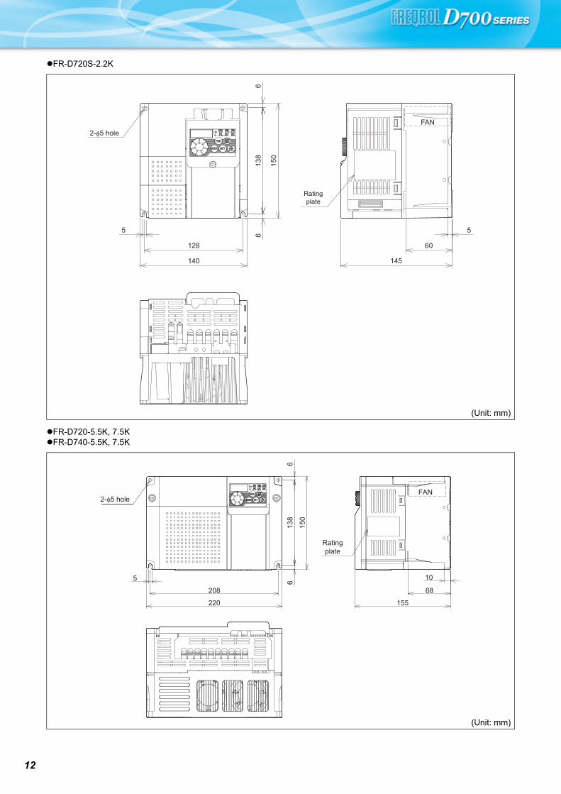
12
FR-D720S-2.2K
FR-D720-5.5K, 7.5KFR-D740-5.5K, 7.5K
(Unit: mm)
(Unit: mm)
2-φ5 hole
Rating
plate
128
140
5
13
86
6
15
0
FAN
5
60
145
2-φ5 hole
Rating
plate
61
38
6
15
0
208
5
220
10
68
155
FAN
Fe
atu
res
Op
tio
ns
Sta
nd
ard
Speci
ficatio
ns
Pa
ram
ete
r
Lis
t
Pro
tective
Fu
nctio
ns
Term
inal
Con
nect
ion
Dia
gram
Term
inal
Spe
cific
atio
nEx
plan
atio
n
Ou
tlin
eD
ime
nsio
nD
raw
ing
sIn
str
uctio
ns
FR
-D70
0 S
erie
sS
peci
ficat
ion
Diff
eren
ce L
ist
Wa
rra
nty
Inte
rna
tio
na
l F
A C
en
ter
Ope
ratio
n pa
nel
Par
amet
er u
nit
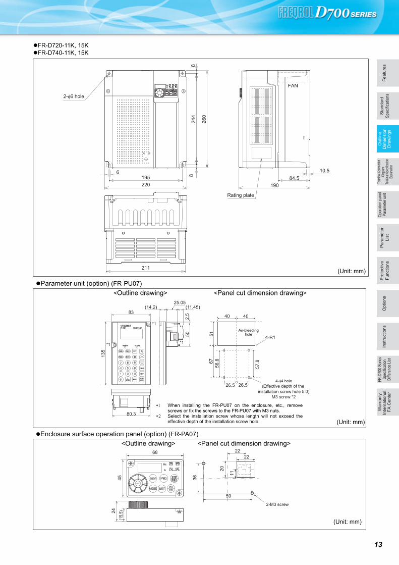
FR-D720-11K, 15KFR-D740-11K, 15K
(Unit: mm)
Parameter unit (option) (FR-PU07)
<Outline drawing> <Panel cut dimension drawing>
Enclosure surface operation panel (option) (FR-PA07)
<Outline drawing> <Panel cut dimension drawing>
824
4
260
220
10.584.5
190
211
FAN
1956 8
2-φ6 hole
Rating plate
4-φ4 hole
(Effective depth of the
installation screw hole 5.0)
M3 screw *2
80.3
(14.2)
2.5
50
(11.45)25.05
13
5
83
*1
*1
*1
*1
67
51
40
56
.8
57
.8
26.5
4-R1
26.5
40
Air-bleeding hole
When installing the FR-PU07 on the enclosure, etc., removescrews or fix the screws to the FR-PU07 with M3 nuts.
Select the installation screw whose length will not exceed theeffective depth of the installation screw hole. (Unit: mm)
2-M3 screw
68
45
59
36
22
22
112
0
(15.
5)24
(Unit: mm)
13
14
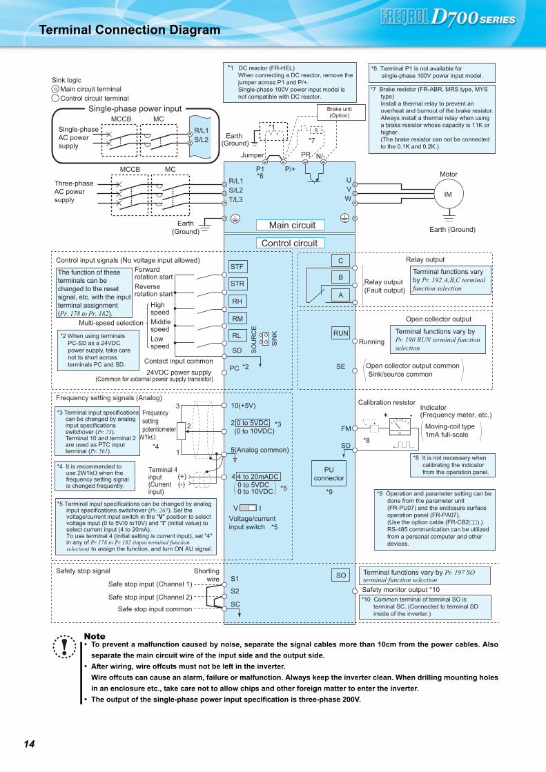
Terminal Connection Diagram
Note To prevent a malfunction caused by noise, separate the signal cables more than 10cm from the power cables. Also
separate the main circuit wire of the input side and the output side.
After wiring, wire offcuts must not be left in the inverter.
Wire offcuts can cause an alarm, failure or malfunction. Always keep the inverter clean. When drilling mounting holes
in an enclosure etc., take care not to allow chips and other foreign matter to enter the inverter.
The output of the single-phase power input specification is three-phase 200V.
Earth (Ground)
Motor
IM
Earth (Ground)
Three-phase AC power supply
MCCB MC
R/L1
P1 P/+
PR N/-
S/L2T/L3
UVW
Earth(Ground)
*7 Brake resistor (FR-ABR, MRS type, MYS type)Install a thermal relay to prevent an overheat and burnout of the brake resistor.Always install a thermal relay when using a brake resistor whose capacity is 11K or higher.(The brake resistor can not be connected to the 0.1K and 0.2K.)
*8 It is not necessary when calibrating the indicator from the operation panel.
*9 Operation and parameter setting can be done from the parameter unit (FR-PU07) and the enclosure surface operation panel (FR-PA07).(Use the option cable (FR-CB2 ).)RS-485 communication can be utilized from a personal computer and other devices.
Forward rotation startReverse rotation start
Middle speed
High speed
Low speed
Control input signals (No voltage input allowed)
24VDC power supply (Common for external power supply transistor)
Contact input common
STR
STF
RH
RM
RL
SD
PC
Relay output
Running
Open collector output
Open collector output commonSink/source common
RUN
SE
A
B
C
Frequency setting signals (Analog)
2 0 to 5VDC
10(+5V)
2
3
1
4 4 to 20mADC
Frequency setting potentiometer
1/2W1kΩ
Terminal 4 input(Current input)
(+)(-)
5(Analog common)
*4 It is recommended to use 2W1kΩ when the frequency setting signal is changed frequently.
*4
*2 When using terminals PC-SD as a 24VDC power supply, take care not to short across terminals PC and SD.
PUconnector
*1 DC reactor (FR-HEL)When connecting a DC reactor, remove the jumper across P1 and P/+.Single-phase 100V power input model is not compatible with DC reactor.Control circuit terminal
Main circuit terminalSink logic
Jumper
*1
*7
*6
*2
*3
*5
The function of these terminals can be changed to the reset signal, etc. with the input terminal assignment (Pr. 178 to Pr. 182).
Multi-speed selectionTerminal functions vary by Pr. 190 RUN terminal function selection
Terminal functions vary by Pr. 192 A,B,C terminal function selection
SIN
K
SO
UR
CE
V I
*5
0 to 5VDC
(0 to 10VDC)
0 to 10VDC
*5 Terminal input specifications can be changed by analog input specifications switchover (Pr. 267). Set the voltage/current input switch in the "V" position to select voltage input (0 to 5V/0 to10V) and "I" (initial value) to select current input (4 to 20mA).To use terminal 4 (initial setting is current input), set "4" in any of Pr.178 to Pr.182 (input terminal function selection) to assign the function, and turn ON AU signal.
Voltage/current input switch
Main circuit
Control circuit
R
Relay output(Fault output)
Brake unit(Option)
FM
SD
Indicator(Frequency meter, etc.)+ -
Moving-coil type1mA full-scale
Calibration resistor
*8
*9
*3 Terminal input specifications can be changed by analog input specifications switchover (Pr. 73).Terminal 10 and terminal 2 are used as PTC input terminal (Pr. 561).
Safe stop input (Channel 1)
Safe stop input (Channel 2)
Safe stop input common
Safety stop signalS1
S2
SC
SOShorting wire
Single-phase AC power supply
MCCB MC
R/L1S/L2
Single-phase power input
*6 Terminal P1 is not available for single-phase 100V power input model.
*10 Common terminal of terminal SO is terminal SC. (Connected to terminal SD inside of the inverter.)
Safety monitor output *10
Terminal functions vary by Pr. 197 SO terminal function selection
Fe
atu
res
Op
tio
ns
Sta
nd
ard
Speci
ficatio
ns
Pa
ram
ete
r
Lis
t
Pro
tective
Fu
nctio
ns
Term
inal
Con
nect
ion
Dia
gram
Term
inal
Spe
cific
atio
nEx
plan
atio
n
Ou
tlin
eD
ime
nsio
nD
raw
ing
sIn
str
uctio
ns
FR
-D70
0 S
erie
sS
peci
ficat
ion
Diff
eren
ce L
ist
Wa
rra
nty
Inte
rna
tio
na
l F
A C
en
ter
Ope
ratio
n pa
nel
Par
amet
er u
nit
15
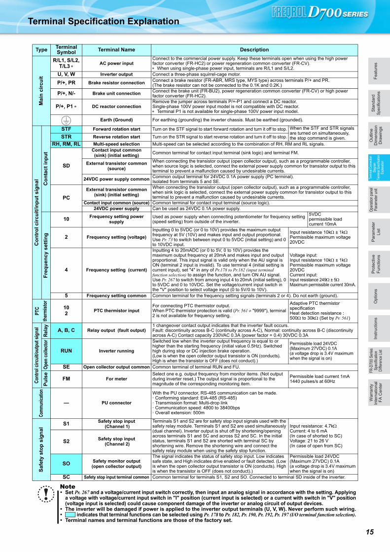
Terminal Specification Explanation
Type Terminal Symbol Terminal Name Description
Mai
n c
ircu
it
R/L1, S/L2, T/L3
AC power inputConnect to the commercial power supply. Keep these terminals open when using the high power factor converter (FR-HC2) or power regeneration common converter (FR-CV). When using single-phase power input, terminals are R/L1 and S/L2.
U, V, W Inverter output Connect a three-phase squirrel-cage motor.
P/+, PR Brake resistor connection Connect a brake resistor (FR-ABR, MRS type, MYS type) across terminals P/+ and PR.(The brake resistor can not be connected to the 0.1K and 0.2K.)
P/+, N/- Brake unit connection Connect the brake unit (FR-BU2), power regeneration common converter (FR-CV) or high power factor converter (FR-HC2).
P/+, P1 DC reactor connectionRemove the jumper across terminals P/+-P1 and connect a DC reactor.Single-phase 100V power input model is not compatible with DC reactor. Terminal P1 is not available for single-phase 100V power input model.
Earth (Ground) For earthing (grounding) the inverter chassis. Must be earthed (grounded).
Co
ntr
ol c
ircu
it/in
pu
t si
gn
al Co
nta
ct in
pu
t
STF Forward rotation start Turn on the STF signal to start forward rotation and turn it off to stop. When the STF and STR signals are turned on simultaneously, the stop command is given. STR Reverse rotation start Turn on the STR signal to start reverse rotation and turn it off to stop.
RH, RM, RL Multi-speed selection Multi-speed can be selected according to the combination of RH, RM and RL signals.
SD
Contact input common(sink) (initial setting)
Common terminal for contact input terminal (sink logic) and terminal FM.
External transistor common (source)
When connecting the transistor output (open collector output), such as a programmable controller, when source logic is selected, connect the external power supply common for transistor output to this terminal to prevent a malfunction caused by undesirable currents.
24VDC power supply common Common output terminal for 24VDC 0.1A power supply (PC terminal).Isolated from terminals 5 and SE.
PC
External transistor common (sink) (initial setting)
When connecting the transistor output (open collector output), such as a programmable controller, when sink logic is selected, connect the external power supply common for transistor output to this terminal to prevent a malfunction caused by undesirable currents.
Contact input common (source) Common terminal for contact input terminal (source logic).24VDC power supply Can be used as 24VDC 0.1A power supply.
Fre
qu
ency
set
tin
g
10 Frequency setting power supply
Used as power supply when connecting potentiometer for frequency setting (speed setting) from outside of the inverter.
5VDCpermissible load current 10mA
2 Frequency setting (voltage)
Inputting 0 to 5VDC (or 0 to 10V) provides the maximum output frequency at 5V (10V) and makes input and output proportional. Use Pr. 73 to switch between input 0 to 5VDC (initial setting) and 0 to 10VDC input.
Input resistance 10k ± 1kPermissible maximum voltage 20VDC
4 Frequency setting (current)
Inputting 4 to 20mADC (or 0 to 5V, 0 to 10V) provides the maximum output frequency at 20mA and makes input and output proportional. This input signal is valid only when the AU signal is ON (terminal 2 input is invalid). To use terminal 4 (initial setting is current input), set "4" in any of Pr.178 to Pr.182 (input terminal function selection) to assign the function, and turn ON AU signal.Use Pr. 267 to switch from among input 4 to 20mA (initial setting), 0 to 5VDC and 0 to 10VDC. Set the voltage/current input switch in the "V" position to select voltage input (0 to 5V/0 to 10V).
Voltage input: Input resistance 10k ± 1kPermissible maximum voltage 20VDCCurrent input: Input resistance 249 ± 5Maximum permissible current 30mA.
5 Frequency setting common Common terminal for the frequency setting signals (terminals 2 or 4). Do not earth (ground).
PTC
ther
mis
tor
102
PTC thermistor inputFor connecting PTC thermistor output.When PTC thermistor protection is valid (Pr. 561 "9999"), terminal 2 is not available for frequency setting.
Adaptive PTC thermistor specificationHeat detection resistance : 500 to 30k (Set by Pr. 561)
Con
trol
circ
uit/o
utpu
t sig
nal
Rel
ay A, B, C Relay output (fault output)1 changeover contact output indicates that the inverter fault occurs.Fault: discontinuity across B-C (continuity across A-C), Normal: continuity across B-C (discontinuity across A-C) Contact capacity 230VAC 0.3A (power factor = 0.4) 30VDC 0.3A
Ope
n co
llect
or
RUN Inverter running
Switched low when the inverter output frequency is equal to or higher than the starting frequency (initial value 0.5Hz). Switched high during stop or DC injection brake operation.(Low is when the open collector output transistor is ON (conducts). High is when the transistor is OFF (does not conduct).)
Permissible load 24VDC (Maximum 27VDC) 0.1A(a voltage drop is 3.4V maximum when the signal is on)
SE Open collector output common Common terminal of terminal RUN and FU.
Pu
lse
FM For meterSelect one e.g. output frequency from monitor items. (Not output during inverter reset.)The output signal is proportional to the magnitude of the corresponding monitoring item.
Permissible load current 1mA1440 pulses/s at 60Hz
Com
mun
icat
ion
— PU connector
With the PU connector, RS-485 communication can be made.· Conforming standard: EIA-485 (RS-485)· Transmission format: Multi-drop link· Communication speed: 4800 to 38400bps· Overall extension: 500m
Saf
ety
sto
p s
ign
al
S1 Safety stop input (Channel 1)
Terminals S1 and S2 are for safety stop input signals used with the safety relay module. Terminals S1 and S2 are used simultaneously (dual channel). Inverter output is shut off by shortening/opening across terminals S1 and SC and across S2 and SC. In the initial status, terminals S1 and S2 are shorted with terminal SC by shortening wire. Remove the shortening wire and connect the safety relay module when using the safety stop function.
Input resistance: 4.7kCurrent: 4 to 6 mA (In case of shorted to SC)Voltage: 21 to 26 V (In case of open from SC)
S2 Safety stop input (Channel 2)
SO Safety monitor output (open collector output)
The signal indicates the status of safety stop input. Low indicates safe state, and High indicates drive enabled or fault detected. (Low is when the open collector output transistor is ON (conducts). High is when the transistor is OFF (does not conduct).)
Permissible load 24VDC (Maximum 27VDC) 0.1A(a voltage drop is 3.4V maximum when the signal is on)
SC Safety stop input terminal common Common terminal for terminals S1, S2 and SO. Connected to terminal SD inside of the inverter.
Note Set Pr. 267 and a voltage/current input switch correctly, then input an analog signal in accordance with the setting. Applying
a voltage with voltage/current input switch in "I" position (current input is selected) or a current with switch in "V" position(voltage input is selected) could cause component damage of the inverter or analog circuit of output devices.
The inverter will be damaged if power is applied to the inverter output terminals (U, V, W). Never perform such wiring. indicates that terminal functions can be selected using Pr. 178 to Pr. 182, Pr. 190, Pr. 192, Pr. 197 (I/O terminal function selection). Terminal names and terminal functions are those of the factory set.
16
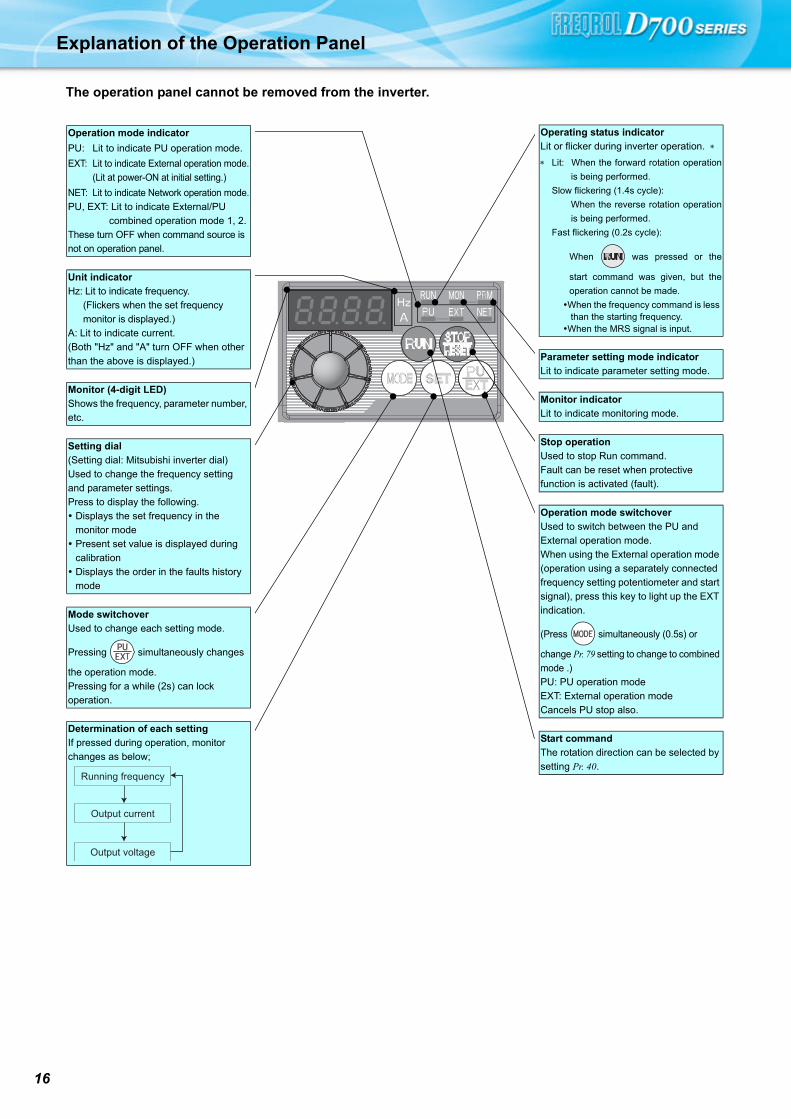
Explanation of the Operation Panel
The operation panel cannot be removed from the inverter.
Operation mode indicator
PU: Lit to indicate PU operation mode.
EXT: Lit to indicate External operation mode.
(Lit at power-ON at initial setting.)
NET: Lit to indicate Network operation mode.
PU, EXT: Lit to indicate External/PU
combined operation mode 1, 2.
These turn OFF when command source is
not on operation panel.
Unit indicator
Hz: Lit to indicate frequency.
(Flickers when the set frequency
monitor is displayed.)
A: Lit to indicate current.
(Both "Hz" and "A" turn OFF when other
than the above is displayed.)
Monitor (4-digit LED)
Shows the frequency, parameter number,
etc.
Setting dial
(Setting dial: Mitsubishi inverter dial)
Used to change the frequency setting
and parameter settings.
Press to display the following.
Displays the set frequency in the
monitor mode
Present set value is displayed during
calibration
Displays the order in the faults history
mode
Mode switchover
Used to change each setting mode.
Pressing simultaneously changes
the operation mode.
Pressing for a while (2s) can lock
operation.
Determination of each setting
If pressed during operation, monitor
changes as below;
Running frequency
Output current
Output voltage
Operating status indicator
Lit or flicker during inverter operation.
Lit: When the forward rotation operation
is being performed.
Slow flickering (1.4s cycle):
When the reverse rotation operation
is being performed.
Fast flickering (0.2s cycle):
When was pressed or the
start command was given, but the
operation cannot be made.
When the frequency command is less than the starting frequency.When the MRS signal is input.
Parameter setting mode indicator
Lit to indicate parameter setting mode.
Monitor indicator
Lit to indicate monitoring mode.
Stop operation
Used to stop Run command.
Fault can be reset when protective
function is activated (fault).
Operation mode switchover
Used to switch between the PU and
External operation mode.
When using the External operation mode
(operation using a separately connected
frequency setting potentiometer and start
signal), press this key to light up the EXT
indication.
(Press simultaneously (0.5s) or
change Pr. 79 setting to change to combined
mode .)
PU: PU operation mode
EXT: External operation mode
Cancels PU stop also.
Start command
The rotation direction can be selected by
setting Pr. 40.
Fe
atu
res
Op
tio
ns
Sta
nd
ard
Speci
ficatio
ns
Pa
ram
ete
r
Lis
t
Pro
tective
Fu
nctio
ns
Term
inal
Con
nect
ion
Dia
gram
Term
inal
Spe
cific
atio
nEx
plan
atio
n
Ou
tlin
eD
ime
nsio
nD
raw
ing
sIn
str
uctio
ns
FR
-D70
0 S
erie
sS
peci
ficat
ion
Diff
eren
ce L
ist
Wa
rra
nty
Inte
rna
tio
na
l F
A C
en
ter
Ope
ratio
n pa
nel
Par
amet
er u
nit
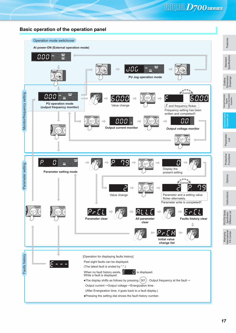
Basic operation of the operation panel
STOP
Operation mode switchover
Par
amet
er s
ettin
gFa
ults
his
tory
Mon
itor/f
requ
ency
set
ting
At power-ON (External operation mode)
PU operation mode(output frequency monitor)
Parameter setting mode
PU Jog operation mode
Output current monitor Output voltage monitor
Display the present setting
Value change
Value change
Parameter write is completed!!
Parameter and a setting value flicker alternately.
Parameter clear All parameterclear
Faults history clear
Initial value change list
(Example)
(Example)
Frequency setting has been written and completed!!
and frequency flicker.
[Operation for displaying faults history]
Past eight faults can be displayed.(The latest fault is ended by ".".)
When no fault history exists, is displayed.While a fault is displayed:
�The display shifts as follows by pressing : Output frequency at the fault
Output current Output voltage Energization time.
(After Energization time, it goes back to a fault display.)
�Pressing the setting dial shows the fault history number.
17
18
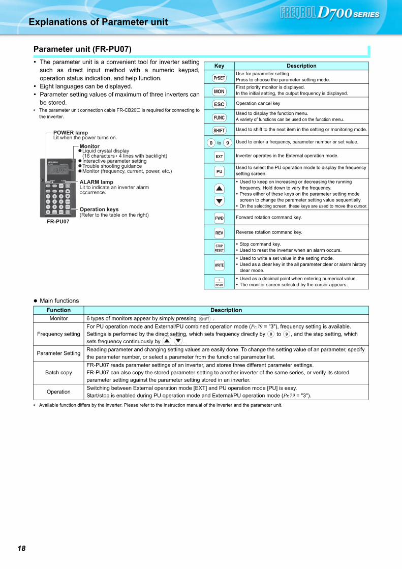
Explanations of Parameter unit
The parameter unit is a convenient tool for inverter settingsuch as direct input method with a numeric keypad,operation status indication, and help function.
Eight languages can be displayed. Parameter setting values of maximum of three inverters can
be stored. The parameter unit connection cable FR-CB20 is required for connecting to
the inverter.
Main functions
Available function differs by the inverter. Please refer to the instruction manual of the inverter and the parameter unit.
Parameter unit (FR-PU07)
POWER lampLit when the power turns on.
MonitorLiquid crystal display(16 characters 4 lines with backlight)Interactive parameter settingTrouble shooting guidanceMonitor (frequency, current, power, etc.)
ALARM lampLit to indicate an inverter alarm occurrence.
FR-PU07
Operation keys(Refer to the table on the right)
Key Description
Use for parameter settingPress to choose the parameter setting mode.
First priority monitor is displayed.In the initial setting, the output frequency is displayed.
Operation cancel key
Used to display the function menu.A variety of functions can be used on the function menu.
Used to shift to the next item in the setting or monitoring mode.
to Used to enter a frequency, parameter number or set value.
Inverter operates in the External operation mode.
Used to select the PU operation mode to display the frequency setting screen.
Used to keep on increasing or decreasing the running frequency. Hold down to vary the frequency. Press either of these keys on the parameter setting mode
screen to change the parameter setting value sequentially. On the selecting screen, these keys are used to move the cursor.
Forward rotation command key.
Reverse rotation command key.
Stop command key. Used to reset the inverter when an alarm occurs.
Used to write a set value in the setting mode. Used as a clear key in the all parameter clear or alarm history
clear mode.
Used as a decimal point when entering numerical value. The monitor screen selected by the cursor appears.
Function Description
Monitor 6 types of monitors appear by simply pressing .
Frequency settingFor PU operation mode and External/PU combined operation mode (Pr.79 = "3"), frequency setting is available.Settings is performed by the direct setting, which sets frequency directly by to , and the step setting, which sets frequency continuously by .
Parameter SettingReading parameter and changing setting values are easily done. To change the setting value of an parameter, specify the parameter number, or select a parameter from the functional parameter list.
Batch copyFR-PU07 reads parameter settings of an inverter, and stores three different parameter settings.FR-PU07 can also copy the stored parameter setting to another inverter of the same series, or verify its stored parameter setting against the parameter setting stored in an inverter.
OperationSwitching between External operation mode [EXT] and PU operation mode [PU] is easy.Start/stop is enabled during PU operation mode and External/PU operation mode (Pr.79 = "3").

Parameter List
Fe
atu
res
Op
tio
ns
Sta
nd
ard
Speci
ficatio
ns
Pa
ram
ete
r
Lis
t
Pro
tective
Fu
nctio
ns
Term
inal
Con
nect
ion
Dia
gram
Term
inal
Spe
cific
atio
nEx
plan
atio
n
Ou
tlin
eD
ime
nsio
nD
raw
ing
sIn
str
uctio
ns
FR
-D70
0 S
erie
sS
peci
ficat
ion
Diff
eren
ce L
ist
Wa
rra
nty
Inte
rna
tio
na
l F
A C
en
ter
Ope
ratio
n pa
nel
Par
amet
er u
nit
For simple variable-speed operation of the inverter, the initial setting of the parameters may be used as they are. Set the
necessary parameters to meet the load and operational specifications. Parameter setting, change and check can be made
from the operation panel. For details of parameters, refer to the Instruction Manual.
This catalog explains based on the Japanese specifications.
POINTOnly simple mode parameters are displayed by the initial setting of Pr. 160 Extended function display selection. Set Pr.
160 Extended function display selection as required.
Pr. 160 Description
9999
(initial value)Parameters classified as simple mode can be displayed.
0Both the parameters classified as simple mode and the parameters
classified as extended mode can be displayed.
Parameter
NumberName Unit
Initial
ValueRange Application
0 Torque boost 0.1%6%/4%/3/
2%0 to 30%
Set when you want to increase a
starting torque under V/F control,
or when the motor with a load will
not rotate, resulting in an alarm
[OL] and a trip [OC1].
Initial values differ according to the
inverter capacity. (0.75K or less/
1.5K to 3.7K/5.5K, 7.5K/11K, 15K)
1 Maximum frequency 0.01Hz 120Hz 0 to 120HzSet when the maximum output
frequency need to be limited.
2 Minimum frequency 0.01Hz 0Hz 0 to 120HzSet when the minimum output
frequency need to be limited.
3 Base frequency 0.01Hz 60Hz 0 to 400Hz
Set when the rated motor
frequency is 50Hz.
Check the motor rating plate.
4Multi-speed setting
(high speed)0.01Hz 60Hz 0 to 400Hz
Set when changing the preset
speed in the parameter with a
terminal.
5Multi-speed setting
(middle speed)0.01Hz 30Hz 0 to 400Hz
6Multi-speed setting (low
speed)0.01Hz 10Hz 0 to 400Hz
7 Acceleration time 0.1s 5s/10s/15s 0 to 3600sAcceleration/deceleration time can
be set.
Initial values differ according to the
inverter capacity. (3.7K or less/
5.5K, 7.5K/11K, 15K)8 Deceleration time 0.1s 5s/10s/15s 0 to 3600s
9Electronic thermal O/L
relay0.01A
Rated
inverter
current
0 to 500A
The inverter protects the motor
from overheat.
Set the rated motor current.
79Operation mode
selection1 0
0, 1, 2, 3, 4, 6,
7
Select the start command location
and frequency setting location.
125Terminal 2 frequency
setting gain frequency0.01Hz 60Hz 0 to 400Hz
Frequency for the maximum value
of the potentiometer (5V initial
value) can be changed.
126Terminal 4 frequency
setting gain frequency0.01Hz 60Hz 0 to 400Hz
Frequency for the maximum
current input (20mA initial value)
can be changed.
160Extended function
display selection1 9999 0, 9999
Parameter which can be read from
the operation panel and parameter
unit (FR-PU07) can be restricted.
19

20
Paramete
0
1
2
3
4
5
6
7
8
9
10
11
12
13
14
15
16
17
18
19
20
22
23
24
25
26
27
29
30
31
32
33
34
35
36
37
40
41
42
43
Extended mode parameter
REMARKS indicates simple mode parameters.
The shaded parameters in the table allow its setting to be changed during operation even if "0" (initial value) is set in Pr. 77
Parameter write selection.
Func-tion
Parameter Name Setting RangeMinimum Setting
Increments
Initial Value
Customer Setting
Bas
ic fu
nctio
ns
0 Torque boost 0 to 30% 0.1% 6/4/3/2%
1 Maximum frequency 0 to 120Hz 0.01Hz 120Hz
2 Minimum frequency 0 to 120Hz 0.01Hz 0Hz
3 Base frequency 0 to 400Hz 0.01Hz 60Hz
4 Multi-speed setting (high speed) 0 to 400Hz 0.01Hz 60Hz
5 Multi-speed setting (middle speed) 0 to 400Hz 0.01Hz 30Hz
6 Multi-speed setting (low speed) 0 to 400Hz 0.01Hz 10Hz
7 Acceleration time 0 to 3600s 0.1s 5/10/15s
8 Deceleration time 0 to 3600s 0.1s 5/10/15s
9 Electronic thermal O/L relay 0 to 500A 0.01ARated
inverter current
DC
inje
ctio
n
brak
e
10 DC injection brake operation frequency 0 to 120Hz 0.01Hz 3Hz
11 DC injection brake operation time 0 to 10s 0.1s 0.5s
12 DC injection brake operation voltage 0 to 30% 0.1% 6/4/2%
— 13 Starting frequency 0 to 60Hz 0.01Hz 0.5Hz
— 14 Load pattern selection 0 to 3 1 0
JOG
oper
atio
n 15 Jog frequency 0 to 400Hz 0.01Hz 5Hz
16 Jog acceleration/deceleration time 0 to 3600s 0.1s 0.5s
— 17 MRS input selection 0, 2, 4 1 0
— 18 High speed maximum frequency 120 to 400Hz 0.01Hz 120Hz
— 19 Base frequency voltage 0 to 1000V, 8888, 9999 0.1V 9999
Acc
ele
ratio
n/
dece
lera
tion
time
20Acceleration/deceleration reference frequency
1 to 400Hz 0.01Hz 60Hz
Sta
ll
prev
entio
n
22 Stall prevention operation level 0 to 200% 0.1% 150%
23Stall prevention operation level compensation factor at double speed
0 to 200%, 9999 0.1% 9999
Mul
ti-sp
eed
sett
ing
24 Multi-speed setting (speed 4) 0 to 400Hz, 9999 0.01Hz 9999
25 Multi-speed setting (speed 5) 0 to 400Hz, 9999 0.01Hz 9999
26 Multi-speed setting (speed 6) 0 to 400Hz, 9999 0.01Hz 9999
27 Multi-speed setting (speed 7) 0 to 400Hz, 9999 0.01Hz 9999
— 29Acceleration/deceleration pattern selection
0, 1, 2 1 0
— 30 Regenerative function selection 0, 1, 2 1 0
Fre
quen
cy ju
mp 31 Frequency jump 1A 0 to 400Hz, 9999 0.01Hz 9999
32 Frequency jump 1B 0 to 400Hz, 9999 0.01Hz 9999
33 Frequency jump 2A 0 to 400Hz, 9999 0.01Hz 9999
34 Frequency jump 2B 0 to 400Hz, 9999 0.01Hz 9999
35 Frequency jump 3A 0 to 400Hz, 9999 0.01Hz 9999
36 Frequency jump 3B 0 to 400Hz, 9999 0.01Hz 9999
— 37 Speed display 0, 0.01 to 9998 0.001 0
— 40 RUN key rotation direction selection 0, 1 1 0
Fre
quen
cy
dete
ctio
n 41 Up-to-frequency sensitivity 0 to 100% 0.1% 10%
42 Output frequency detection 0 to 400Hz 0.01Hz 6Hz
43Output frequency detection for reverse rotation
0 to 400Hz, 9999 0.01Hz 9999
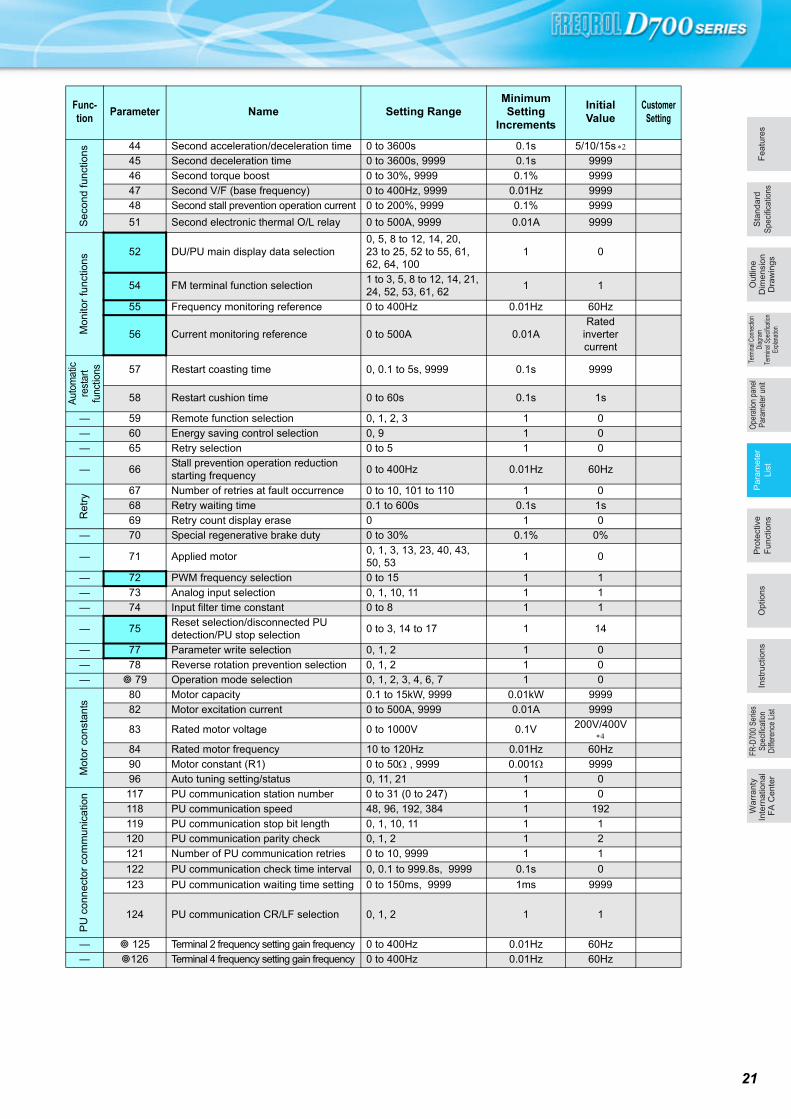
Fe
atu
res
Op
tio
ns
Sta
nd
ard
Speci
ficatio
ns
Pa
ram
ete
r
Lis
t
Pro
tective
Fu
nctio
ns
Term
inal
Con
nect
ion
Dia
gram
Term
inal
Spe
cific
atio
nEx
plan
atio
n
Ou
tlin
eD
ime
nsio
nD
raw
ing
sIn
str
uctio
ns
FR
-D70
0 S
erie
sS
peci
ficat
ion
Diff
eren
ce L
ist
Wa
rra
nty
Inte
rna
tio
na
l F
A C
en
ter
Ope
ratio
n pa
nel
Par
amet
er u
nit
44
45
46
47
48
51
52
54
55
56
57
58
59
60
65
66
67
68
69
70
71
72
73
74
75
77
78
79
80
82
83
84
90
96
117
118
119
120
121
122
123
124
125
126
Paramete
Se
cond
fun
ctio
ns
44 Second acceleration/deceleration time 0 to 3600s 0.1s 5/10/15s
45 Second deceleration time 0 to 3600s, 9999 0.1s 9999
46 Second torque boost 0 to 30%, 9999 0.1% 9999
47 Second V/F (base frequency) 0 to 400Hz, 9999 0.01Hz 9999
48 Second stall prevention operation current 0 to 200%, 9999 0.1% 9999
51 Second electronic thermal O/L relay 0 to 500A, 9999 0.01A 9999
Mon
itor
func
tions
52 DU/PU main display data selection0, 5, 8 to 12, 14, 20, 23 to 25, 52 to 55, 61, 62, 64, 100
1 0
54 FM terminal function selection1 to 3, 5, 8 to 12, 14, 21, 24, 52, 53, 61, 62
1 1
55 Frequency monitoring reference 0 to 400Hz 0.01Hz 60Hz
56 Current monitoring reference 0 to 500A 0.01ARated
inverter current
Aut
omat
ic
rest
art
func
tions 57 Restart coasting time 0, 0.1 to 5s, 9999 0.1s 9999
58 Restart cushion time 0 to 60s 0.1s 1s
— 59 Remote function selection 0, 1, 2, 3 1 0
— 60 Energy saving control selection 0, 9 1 0
— 65 Retry selection 0 to 5 1 0
— 66Stall prevention operation reduction starting frequency
0 to 400Hz 0.01Hz 60Hz
Ret
ry
67 Number of retries at fault occurrence 0 to 10, 101 to 110 1 0
68 Retry waiting time 0.1 to 600s 0.1s 1s
69 Retry count display erase 0 1 0
— 70 Special regenerative brake duty 0 to 30% 0.1% 0%
— 71 Applied motor0, 1, 3, 13, 23, 40, 43, 50, 53
1 0
— 72 PWM frequency selection 0 to 15 1 1
— 73 Analog input selection 0, 1, 10, 11 1 1
— 74 Input filter time constant 0 to 8 1 1
— 75Reset selection/disconnected PU detection/PU stop selection
0 to 3, 14 to 17 1 14
— 77 Parameter write selection 0, 1, 2 1 0
— 78 Reverse rotation prevention selection 0, 1, 2 1 0
— 79 Operation mode selection 0, 1, 2, 3, 4, 6, 7 1 0
Mot
or c
onst
ants
80 Motor capacity 0.1 to 15kW, 9999 0.01kW 9999
82 Motor excitation current 0 to 500A, 9999 0.01A 9999
83 Rated motor voltage 0 to 1000V 0.1V 200V/400V
84 Rated motor frequency 10 to 120Hz 0.01Hz 60Hz
90 Motor constant (R1) 0 to 50 , 9999 0.001 9999
96 Auto tuning setting/status 0, 11, 21 1 0
PU
con
nec
tor
com
mun
icat
ion 117 PU communication station number 0 to 31 (0 to 247) 1 0
118 PU communication speed 48, 96, 192, 384 1 192
119 PU communication stop bit length 0, 1, 10, 11 1 1
120 PU communication parity check 0, 1, 2 1 2
121 Number of PU communication retries 0 to 10, 9999 1 1
122 PU communication check time interval 0, 0.1 to 999.8s, 9999 0.1s 0
123 PU communication waiting time setting 0 to 150ms, 9999 1ms 9999
124 PU communication CR/LF selection 0, 1, 2 1 1
— 125 Terminal 2 frequency setting gain frequency 0 to 400Hz 0.01Hz 60Hz
— 126 Terminal 4 frequency setting gain frequency 0 to 400Hz 0.01Hz 60Hz
Func-tion
Parameter Name Setting RangeMinimum Setting
Increments
Initial Value
Customer Setting
21

22
127
128
129
130
131
132
133
134
145
146
150
151
152
153
154
156
157
160
161
162
165
166
167
168
169
170
171
178
179
180
181
182
Paramete
PID
ope
ratio
n
127 PID control automatic switchover frequency 0 to 400Hz, 9999 0.01Hz 9999
128 PID action selection 0, 20, 21, 40 to 43 1 0
129 PID proportional band 0.1 to 1000%, 9999 0.1% 100%
130 PID integral time 0.1 to 3600s, 9999 0.1s 1s
131 PID upper limit 0 to 100%, 9999 0.1% 9999
132 PID lower limit 0 to 100%, 9999 0.1% 9999
133 PID action set point 0 to 100%, 9999 0.01% 9999
134 PID differential time 0.01 to 10s, 9999 0.01s 9999
PU 145 PU display language selection 0 to 7 1 0
— 146 Built-in potentiometer switching 0, 1 1 1
Cur
rent
dete
ctio
n 150 Output current detection level 0 to 200% 0.1% 150%
151 Output current detection signal delay time 0 to 10s 0.1s 0s
152 Zero current detection level 0 to 200% 0.1% 5%
153 Zero current detection time 0 to 1s 0.01s 0.5s
— 154Voltage reduction selection during stall prevention operation
1, 11 1 1
— 156 Stall prevention operation selection 0 to 31, 100, 101 1 0
— 157 OL signal output timer 0 to 25s, 9999 0.1s 0s
— 160 Extended function display selection 0, 9999 1 9999
— 161 Frequency setting/key lock operation selection 0, 1, 10, 11 1 0
Au
tom
atic
rest
art
fun
ctio
ns
162Automatic restart after instantaneous power failure selection
0, 1, 10, 11 1 1
165Stall prevention operation level for restart
0 to 200% 0.1% 150%
Cur
rent
det
ect
ion
166Output current detection signal retention time
0 to 10s, 9999 0.1s 0.1s
167Output current detection operation selection
0, 1 1 0
— 168Parameter for manufacturer setting. Do not set.
— 169
Cum
ulat
ive
mon
itor
clea
r
170 Watt-hour meter clear 0, 10, 9999 1 9999
171 Operation hour meter clear 0, 9999 1 9999
Inpu
t ter
min
al fu
nctio
n
ass
ign
men
t
178 STF terminal function selection0 to 5, 7, 8, 10, 12, 14, 16, 18, 24, 25, 60, 62, 65 to 67, 9999
1 60
179 STR terminal function selection0 to 5, 7, 8, 10, 12, 14, 16, 18, 24, 25, 61, 62, 65 to 67, 9999
1 61
180 RL terminal function selection0 to 5, 7, 8, 10, 12, 14, 16, 18, 24, 25, 62, 65 to 67, 9999
1 0
181 RM terminal function selection 1 1
182 RH terminal function selection 1 2
Func-tion
Parameter Name Setting RangeMinimum Setting
Increments
Initial Value
Customer Setting

Fe
atu
res
Op
tio
ns
Sta
nd
ard
Speci
ficatio
ns
Pa
ram
ete
r
Lis
t
Pro
tective
Fu
nctio
ns
Term
inal
Con
nect
ion
Dia
gram
Term
inal
Spe
cific
atio
nEx
plan
atio
n
Ou
tlin
eD
ime
nsio
nD
raw
ing
sIn
str
uctio
ns
FR
-D70
0 S
erie
sS
peci
ficat
ion
Diff
eren
ce L
ist
Wa
rra
nty
Inte
rna
tio
na
l F
A C
en
ter
Ope
ratio
n pa
nel
Par
amet
er u
nit
190
192
197
232
233
234
235
236
237
238
239
240
241
244
245
246
247
249
250
251
255
256
257
258
259
260
261
267
268
269
295
296
297
298
Paramete
Out
put t
erm
inal
func
tion
assi
gnm
ent
190 RUN terminal function selection
0, 1, 3, 4, 7, 8, 11 to 16, 25, 26, 46, 47, 64, 70, 80, 81, 90, 91, 93, 95, 96, 98, 99, 100, 101, 103, 104, 107, 108, 111 to 116, 125, 126, 146, 147, 164, 170, 180,181, 190, 191, 193, 195, 196, 198, 199, 9999
1 0
192 A,B,C terminal function selection
0, 1, 3, 4, 7, 8, 11 to 16, 25, 26, 46, 47, 64, 70, 80, 81, 90, 91, 95, 96, 98, 99, 100, 101, 103, 104, 107, 108, 111 to 116, 125, 126, 146, 147, 164, 170, 180, 181, 190, 191, 195, 196, 198, 199, 9999
1 99
197 SO terminal function selection
0, 1, 3, 4, 7, 8, 11 to 16, 25, 26, 46, 47, 64, 70, 80, 81, 90, 91, 93, 95, 96, 98, 99, 100, 101, 103, 104, 107, 108, 111 to 116, 125, 126, 146, 147, 164, 170, 180, 181, 190, 191, 193, 195, 196, 198, 199
1 80
Mul
ti-sp
eed
se
tting
232 Multi-speed setting (speed 8) 0 to 400Hz, 9999 0.01Hz 9999
233 Multi-speed setting (speed 9) 0 to 400Hz, 9999 0.01Hz 9999
234 Multi-speed setting (speed 10) 0 to 400Hz, 9999 0.01Hz 9999
235 Multi-speed setting (speed 11) 0 to 400Hz, 9999 0.01Hz 9999
236 Multi-speed setting (speed 12) 0 to 400Hz, 9999 0.01Hz 9999
237 Multi-speed setting (speed 13) 0 to 400Hz, 9999 0.01Hz 9999
238 Multi-speed setting (speed 14) 0 to 400Hz, 9999 0.01Hz 9999
239 Multi-speed setting (speed 15) 0 to 400Hz, 9999 0.01Hz 9999
— 240 Soft-PWM operation selection 0, 1 1 1
— 241 Analog input display unit switchover 0, 1 1 0
— 244 Cooling fan operation selection 0, 1 1 1
Slip
com
pens
atio
n 245 Rated slip 0 to 50%, 9999 0.01% 9999
246 Slip compensation time constant 0.01 to 10s 0.01s 0.5s
247Constant-power range slip compensation selection
0, 9999 1 9999
— 249 Earth (ground) fault detection at start 0, 1 1 0
— 250 Stop selection0 to 100s, 1000 to 1100s, 8888, 9999
0.1s 9999
— 251 Output phase loss protection selection 0, 1 1 1
Life
dia
gnos
is 255 Life alarm status display (0 to 15) 1 0
256 Inrush current limit circuit life display (0 to 100%) 1% 100%
257 Control circuit capacitor life display (0 to 100%) 1% 100%
258 Main circuit capacitor life display (0 to 100%) 1% 100%
259 Main circuit capacitor life measuring 0, 1 (2, 3, 8, 9) 1 0
— 260 PWM frequency automatic switchover 0, 1 1 0
Pow
er fa
ilure
stop 261 Power failure stop selection 0, 1, 2 1 0
— 267 Terminal 4 input selection 0, 1, 2 1 0
— 268 Monitor decimal digits selection 0, 1, 9999 1 9999
— 269 Parameter for manufacturer setting. Do not set.
— 295 Magnitude of frequency change setting0, 0.01, 0.10, 1.00, 10.00
0.01 0
Pa
ssw
ord
func
tion 296 Password lock level 1 to 6, 101 to 106, 9999 1 9999
297 Password lock/unlock1000 to 9998 (0 to 5, 9999)
1 9999
— 298 Frequency search gain 0 to 32767, 9999 1 9999
Func-tion
Parameter Name Setting RangeMinimum Setting
Increments
Initial Value
Customer Setting
23
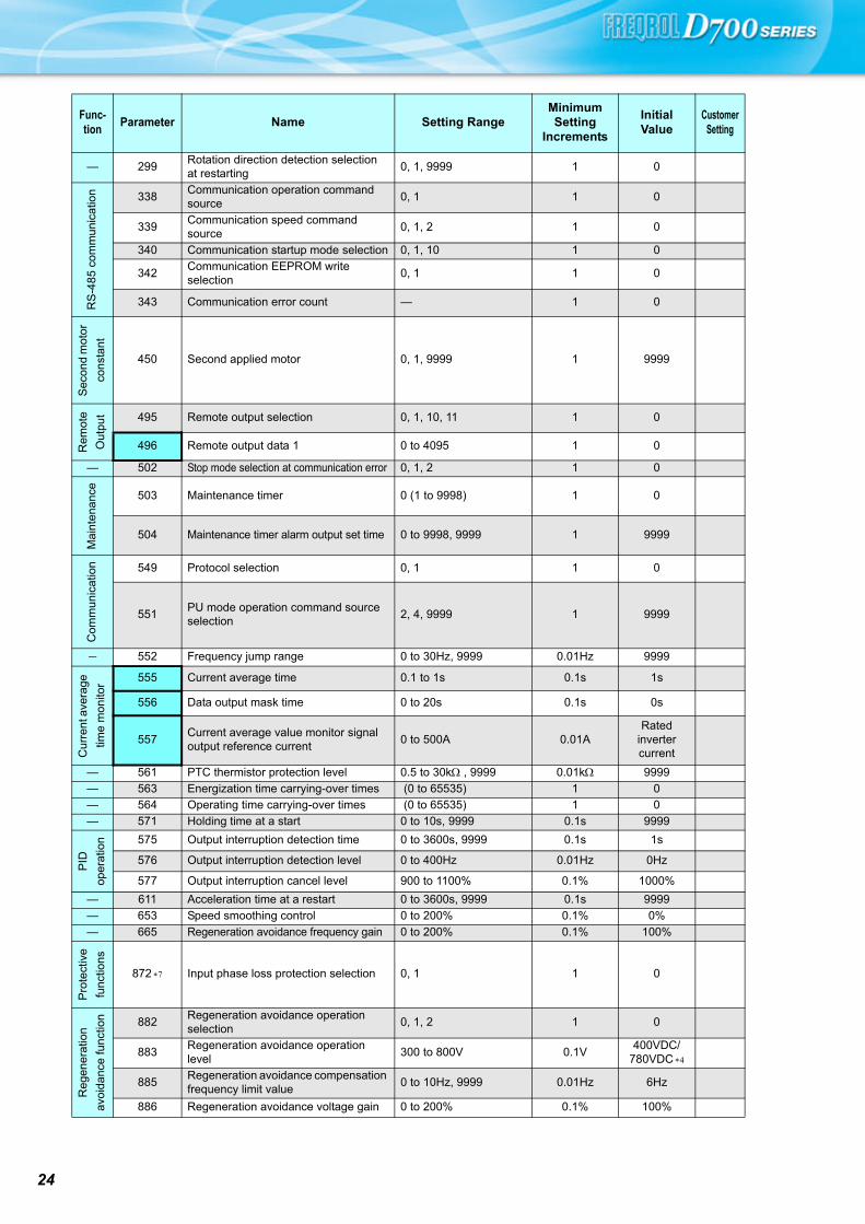
24
299
338
339
340
342
343
450
495
496
502
503
504
549
551
552
555
556
557
561
563
564
571
575
576
577
611
653
665
872
882
883
885
886
Paramete
— 299Rotation direction detection selection at restarting
0, 1, 9999 1 0
RS
-48
5 co
mm
uni
catio
n 338Communication operation command source
0, 1 1 0
339Communication speed command source
0, 1, 2 1 0
340 Communication startup mode selection 0, 1, 10 1 0
342Communication EEPROM write selection
0, 1 1 0
343 Communication error count — 1 0
Sec
ond
mot
or
cons
tant
450 Second applied motor 0, 1, 9999 1 9999
Rem
ote
Out
put 495 Remote output selection 0, 1, 10, 11 1 0
496 Remote output data 1 0 to 4095 1 0
— 502 Stop mode selection at communication error 0, 1, 2 1 0
Mai
nten
anc
e
503 Maintenance timer 0 (1 to 9998) 1 0
504 Maintenance timer alarm output set time 0 to 9998, 9999 1 9999
Com
mun
icat
ion 549 Protocol selection 0, 1 1 0
551PU mode operation command source selection
2, 4, 9999 1 9999
- 552 Frequency jump range 0 to 30Hz, 9999 0.01Hz 9999
Cur
rent
ave
rage
time
mo
nito
r 555 Current average time 0.1 to 1s 0.1s 1s
556 Data output mask time 0 to 20s 0.1s 0s
557Current average value monitor signal output reference current
0 to 500A 0.01ARated
inverter current
— 561 PTC thermistor protection level 0.5 to 30k , 9999 0.01k 9999
— 563 Energization time carrying-over times (0 to 65535) 1 0
— 564 Operating time carrying-over times (0 to 65535) 1 0
— 571 Holding time at a start 0 to 10s, 9999 0.1s 9999
PID
oper
atio
n 575 Output interruption detection time 0 to 3600s, 9999 0.1s 1s
576 Output interruption detection level 0 to 400Hz 0.01Hz 0Hz
577 Output interruption cancel level 900 to 1100% 0.1% 1000%
— 611 Acceleration time at a restart 0 to 3600s, 9999 0.1s 9999
— 653 Speed smoothing control 0 to 200% 0.1% 0%
— 665 Regeneration avoidance frequency gain 0 to 200% 0.1% 100%
Pro
tect
ive
func
tions
872 Input phase loss protection selection 0, 1 1 0
Reg
ener
atio
n
avoi
danc
e fu
nctio
n 882Regeneration avoidance operation selection
0, 1, 2 1 0
883Regeneration avoidance operation level
300 to 800V 0.1V400VDC/
780VDC
885Regeneration avoidance compensation frequency limit value
0 to 10Hz, 9999 0.01Hz 6Hz
886 Regeneration avoidance voltage gain 0 to 200% 0.1% 100%
Func-tion
Parameter Name Setting RangeMinimum Setting
Increments
Initial Value
Customer Setting

Fe
atu
res
Op
tio
ns
Sta
nd
ard
Speci
ficatio
ns
Pa
ram
ete
r
Lis
t
Pro
tective
Fu
nctio
ns
Term
inal
Con
nect
ion
Dia
gram
Term
inal
Spe
cific
atio
nEx
plan
atio
n
Ou
tlin
eD
ime
nsio
nD
raw
ing
sIn
str
uctio
ns
FR
-D70
0 S
erie
sS
peci
ficat
ion
Diff
eren
ce L
ist
Wa
rra
nty
Inte
rna
tio
na
l F
A C
en
ter
Ope
ratio
n pa
nel
Par
amet
er u
nit
888
889
891
C0
(900)
C2
(902)
C3
(902)
125
(903)
C4
(903)
C5
(904)
C6
(904)
126
(905)
C7
(905)
C22
(922)
C23
(922)
C24
(923)
C25
(923)
990
991
Pr.CL
ALLC
Er.CL
Pr.CH
Paramete
Fre
e
para
met
er 888 Free parameter 1 0 to 9999 1 9999
889 Free parameter 2 0 to 9999 1 9999
— 891 Cumulative power monitor digit shifted times 0 to 4, 9999 1 9999
Cal
ibra
tion
para
met
ers
C0
(900) FM terminal calibration — — —
C2
(902)
Terminal 2 frequency setting bias frequency
0 to 400Hz 0.01Hz 0Hz
C3
(902) Terminal 2 frequency setting bias 0 to 300% 0.1% 0%
125
(903)
Terminal 2 frequency setting gain frequency
0 to 400Hz 0.01Hz 60Hz
C4
(903) Terminal 2 frequency setting gain 0 to 300% 0.1% 100%
C5
(904)
Terminal 4 frequency setting bias frequency
0 to 400Hz 0.01Hz 0Hz
C6
(904) Terminal 4 frequency setting bias 0 to 300% 0.1% 20%
126
(905)
Terminal 4 frequency setting gain frequency
0 to 400Hz 0.01Hz 60Hz
C7
(905) Terminal 4 frequency setting gain 0 to 300% 0.1% 100%
C22
(922)
Frequency setting voltage bias frequency (built-in potentiometer)
0 to 400Hz 0.01Hz 0Hz
C23
(922)
Frequency setting voltage bias (built-in potentiometer)
0 to 300% 0.1% 0%
C24
(923)
Frequency setting voltage gain frequency (built-in potentiometer)
0 to 400Hz 0.01Hz 60Hz
C25
(923)
Frequency setting voltage gain (built-in potentiometer)
0 to 300% 0.1% 100%
PU 990 PU buzzer control 0, 1 1 1
991 PU contrast adjustment 0 to 63 1 58
Cle
ar p
ara
met
ers
Initi
al v
alue
ch
ange
list Pr.CL Parameter clear 0, 1 1 0
ALLC All parameter clear 0, 1 1 0
Er.CL Faults history clear 0, 1 1 0
Pr.CH Initial value change list — — —
Differ according to capacities.6%: 0.75K or lower
4%: 1.5K to 3.7K
3%: 5.5K, 7.5K
2%: 11K, 15K
Differ according to capacities. 5s: 3.7K or lower
10s: 5.5K, 7.5K
15s: 11K, 15K
Differ according to capacities.6%: 0.1K, 0.2K
4%: 0.4K to 7.5K
2%: 11K, 15K
The initial value differs according to the voltage class. (100V class, 200V class / 400V class)
Set this parameter when calibrating the operation panel built-in potentiometer for the FR-E500 series operation panel (PA02) connected with cable.
The parameter number in parentheses is the one for use with the operation panel (PA02) for the FR-E500 series or parameter unit (FR-PU07).
Available only for the three-phase power input model.
Func-tion
Parameter Name Setting RangeMinimum Setting
Increments
Initial Value
Customer Setting
25

26
Protective Functions
When a fault occurs, the inverter trips and the PU display automatically changes to any of the following fault or alarm indications.
Resetting the inverter initializes the internal cumulative heat value of the electronic thermal relay function. The error message shows an operational error. The inverter output is not shut off. Warnings are messages given before fault occur. The inverter output is not shut off. Alarms warn the operator of failures with output signals. The inverter output is not shut off. When faults occur, the protective functions are activated to inverter trip and output the fault signals. The external thermal operates only when the OH signal is set in Pr. 178 to Pr. 182 (input terminal function selection). This protective function does not function in the initial status. Protective function activates when Pr.872 Input phase loss protection selection = "1". This protective function is available with the three-phase power input specification model only.
Function Name Description Display
Err
or m
essa
ge
Operation panel lock Appears when operation was tried during operation panel lock.
Password locked Appears when a password restricted parameter is read/written.
Parameter write error Appears when an error occurred during parameter writing.
Inverter reset Appears when the RES signal is on.
War
nin
gs
Stall prevention (overcurrent) Appears during overcurrent stall prevention.
Stall prevention (overvoltage) Appears during overvoltage stall prevention. Appears while the regeneration avoidance function is activated.
Regenerative brake pre-alarmAppears if the regenerative brake duty reaches or exceeds 85% of the Pr. 70 Special regenerative brake duty
value. If the regenerative brake duty reaches 100%, a regenerative overvoltage (E. OV_) occurs.
Electronic thermal relay function pre-alarm Appears when the electronic thermal O/L relay has reached 85% of the specified value.
PU stop Appears when on the operation panel was pressed during external operation.
Maintenance signal output Appears when the cumulative energization time has exceeded the maintenance output timer set value.
Undervoltage Appears when the main circuit power became low voltage.
Safety stop Appears when safety stop function is activated (during output shutoff).
Ala
rms
Fan alarmAppears when the cooling fan remains stopped when operation is required or when the speed has
decreased.
Fau
lt
Overcurrent trip during acceleration Appears when an overcurrent occurred during acceleration.
Overcurrent trip during constant speed Appears when an overcurrent occurred during constant speed operation.
Overcurrent trip during deceleration or stop
Appears when an overcurrent occurred during deceleration and at a stop.
Regenerative overvoltage trip during acceleration
Appears when an overvoltage occurred during acceleration.
Regenerative overvoltage trip during constant speed
Appears when an overvoltage occurred during constant speed operation.
Regenerative overvoltage trip during deceleration or stop
Appears when an overvoltage occurred during deceleration and at a stop.
Inverter overload trip
(electronic thermal O/L relay function)
Appears when the electronic thermal relay function for inverter element protection was activated.
Motor overload trip(electronic thermal O/L relay function)
Appears when the electronic thermal relay function for motor protection was activated.
Heatsink overheat Appears when the heatsink overheated.
Input phase lossAppears if one of the three phases on the inverter input side opened. It may function if phase-to-
phase voltage of the three-phase power input becomes largely unbalanced.
Stall prevention stop Appears when the output frequency drops to 1Hz as a result of deceleration due to the excess motor load.
Brake transistor alarm detectionThis function stops the inverter output if an alarm occurs in the brake circuit, e.g. damaged brake
transistors. In this case, the inverter must be powered off immediately.
Output side earth (ground) fault overcurrent at start Appears when an earth (ground) fault occurred on the inverter's output side. (detects only at a start)
Output phase loss
If one of the three phases (U, V, W) on the inverter's output side (load side) is lost during inverter
operation (except during DC injection brake operation and when output frequency is under 1Hz),
inverter stops the output.
External thermal relay operation Appears when the external thermal relay connected to the OH signal was activated.
PTC thermistor operationAppears when resistance of PTC thermistor connected between terminal 2 and terminal 10 is more
than the value set in Pr. 561 PTC thermistor protection level.
Parameter storage device fault Appears when operation of the element where parameters stored became abnormal. (control board)
PU disconnection
Appears when a communication error between the PU and inverter occurred, the communication
interval exceeded the permissible time during the RS-485 communication with the PU connector, or
communication errors exceeded the number of retries during the RS-485 communication.
Retry count excess Appears when the operation was not restarted within the set number of retries.
CPU fault Appears during the CPU and peripheral circuit errors occurred. /
Output current detection value exceeded Appears when output current exceeded the output current detection level set by the parameter.
Inrush current limit circuit fault Appears when the resistor of the inrush current limit circuit overheated.
Analog input faultAppears if voltage(current) is input to terminal 4 when the setting in Pr.267 Terminal 4 input selection and
the setting of voltage/current input switch are different.
Safety circuit fault Appears when safety circuit is malfunctioning.
to

Fe
atu
res
Op
tio
ns
Sta
nd
ard
Speci
ficatio
ns
Pa
ram
ete
r
Lis
t
Pro
tective
Fu
nctio
ns
Term
inal
Con
nect
ion
Dia
gram
Term
inal
Spe
cific
atio
nEx
plan
atio
n
Ou
tlin
eD
ime
nsio
nD
raw
ing
sIn
str
uctio
ns
FR
-D70
0 S
erie
sS
peci
ficat
ion
Diff
eren
ce L
ist
Wa
rra
nty
Inte
rna
tio
na
l F
A C
en
ter
Ope
ratio
n pa
nel
Par
amet
er u
nit
27
Option and Peripheral Devices
By fitting the following options to the inverter, the inverter is provided with more functions.
Rated power consumption. The power supply specifications of the FR series manual controllers and speed controllers are 200VAC 50Hz, 220V/220VAC 60Hz,and 115VAC 60Hz.
Option list
Name Model Applications, Specifications, etc.Applicable
Inverter
Sta
nd
-alo
ne
sha
red
Parameter unit (8 languages) FR-PU07 Interactive parameter unit with LCD displayShared among all models
Enclosure surface operation panel FR-PA07This operation panel enables inverter operation and monitoring of frequency, etc. from the enclosure surface Shared among
all modelsParameter unit connection cable FR-CB20
Cable for connection of operation panel or parameter unit indicates a cable length. (1m, 3m, 5m)
DIN rail attachment FR-UDA01 to 03 Attachment for installation on DIN railCompatible with the 3.7K or less
AC reactor FR-HALFor harmonic current reduction and inverter input power factor improvement
According to capacitiesDC reactor FR-HEL
EMC Directive compliant noise filter SFFR-E5NFFR-S5NFSA
EMC Directive (EN61800-3 C3) compliant noise filterAccording to capacities
EMC compliant EMC filter installation attachment
FR-A5AT03FR-AAT02FR-E5T
For installation of the inverter to the EMC Directive compliant EMC filter (SF).According to capacities
Radio noise filter FR-BIF(H) For radio noise reduction (connect to the input side)Shared among all modelsLine noise filter
FR- BSF01FR- BLF
For line noise reduction
Filterpack FR-BFP2Combination of power factor improving DC reactor, zero phase reactor, and capacitative filter
Three-phase power input model: compatible with 0.4K or bigger capacity
Brake resistorMRS type,MYS type
For increasing the regenerative braking capability (permissible duty 3%/6%ED)200V: For the 0.4K or more
High-duty brake resistor FR-ABR For increasing the regenerative braking capability (permissible duty 10%/6%ED)
For the 0.4K or more
Brake unitResistor unitDischarging resistor
FR-BU2FR-BRGZG, GRZG type
For increasing the braking capability of the inverter (for high-inertia load or negative load)Brake unit, electrical-discharge resistor and resistor unit are used in combination
Power regeneration common converterStand-alone reactor dedicated for the FR-CV
FR-CVFR-CVL
Unit which can return motor-generated braking energy back to the power supply in common converter system
According to capacities
High power factor converter FR-HC2The high power factor converter switches the converter section on/off to reshape an input current waveform into a sine wave, greatly suppressing harmonics. (Used in combination with the standard accessory.)
Surge voltage suppression filterFR-ASF
Filter for suppressing surge voltage on motor
400V: According to capacities
FR-BMF400V: For the 5.5K or more
FR s
erie
s m
anua
l con
trol
ler/
spee
d co
ntro
ller
Manual controller FR-AXFor independent operation. With frequency meter, frequency potentiometer and start switch.
Shared among all models
DC tach. follower FR-AL For synchronous operation (1VA) by external signal (0 to 5V, 0 to 10V DC)
Three speed selector FR-ATFor three speed switching, among high, middle and low speed operation (1.5VA)
Motorized speed setter FR-FK For remote operation. Allows operation to be controlled from several places (5VA)Ratio setter FR-FH For ratio operation. The ratios of five inverters can be set (3VA)Speed detector FR-FP For tracking operation by a pilot generator (PG) signal (2VA)Master controller FR-FG Master controller (5VA) for parallel operation of multiple (maximum 35) inverters.
Soft starter FR-FCFor soft start and stop. Enables acceleration/deceleration in parallel operation (3VA)
Deviation detector FR-FDFor continuous speed control operation. Used in combination with a deviation sensor or synchro (5VA)
Preamplifier FR-FA Used as an A/V converter or arithmetic amplifier (3VA)
Oth
ers
Pilot generator QVAH-10 For tracking operation. 70V/35VAC 500Hz (at 2500r/min)
Deviation sensor YVGC-500W-NSFor continuous speed control operation (mechanical deviation detection) Output 90VAC/90ºC
Frequency setting potentiometer WA2W 1k For frequency setting. Wire-wound 2W 1k type B characteristic
Analog frequency meter (64mm 60mm)
YM206NRI 1mADedicated frequency meter (graduated to 130Hz). Moving-coil type DC ammeter
Calibration resistor RV24YN 10k For frequency meter calibration. Carbon film type B characteristic
FR Configurator SW3(VFD setup software)
FR-SW3-SETUP-WE
Supports an inverter startup to maintenance.

28
Peripheral devices/cable size list
Vo
ltag
e Applicable
inverter
model
Motor output(kW)
Molded case circuit breaker (MCCB) or earth leakage circuit
breaker (ELB) (NF, NV type)
Input side magnetic
contactorRecommended cable gauge
(mm2) Reactor
Power factor improving (AC or DC) reactor
connection
Power factor improving (AC or DC) reactor
connection
R/L1, S/L2, T/L3
U, V, W FR-HAL FR-HELPower factor improving
(AC or DC) reactor connection
Without With Without With Without With
Thr
ee-P
hase
200
V
FR-D720-0.1K 0.1 5A 5A S-T10 S-T10 2 2 2 0.4K 0.4K
FR-D720-0.2K 0.2 5A 5A S-T10 S-T10 2 2 2 0.4K 0.4K
FR-D720-0.4K 0.4 5A 5A S-T10 S-T10 2 2 2 0.4K 0.4K
FR-D720-0.75K 0.75 10A 5A S-T10 S-T10 2 2 2 0.75K 0.75K
FR-D720-1.5K 1.5 15A 10A S-T10 S-T10 2 2 2 1.5K 1.5K
FR-D720-2.2K 2.2 20A 15A S-T10 S-T10 2 2 2 2.2K 2.2K
FR-D720-3.7K 3.7 30A 30A S-T21 S-T10 3.5 3.5 3.5 3.7K 3.7K
FR-D720-5.5K 5.5 50A 40A S-T21 S-T21 5.5 5.5 5.5 5.5K 5.5K
FR-D720-7.5K 7.5 60A 50A S-T35 S-T35 14 8 8 7.5K 7.5K
FR-D720-11K 11 75A 75A S-T35 S-T35 14 14 14 11K 11K
FR-D720-15K 15 125A 100A S-T50 S-T50 22 22 22 15K 15K
Thr
ee-p
hase
400
V
FR-D740-0.4K 0.4 5A 5A S-T10 S-T10 2 2 2 H0.4K H0.4K
FR-D740-0.75K 0.75 5A 5A S-T10 S-T10 2 2 2 H0.75K H0.75K
FR-D740-1.5K 1.5 10A 10A S-T10 S-T10 2 2 2 H1.5K H1.5K
FR-D740-2.2K 2.2 15A 10A S-T10 S-T10 2 2 2 H2.2K H2.2K
FR-D740-3.7K 3.7 20A 15A S-T10 S-T10 2 2 2 H3.7K H3.7K
FR-D740-5.5K 5.5 30A 20A S-T21 S-T12 3.5 2 2 H5.5K H5.5K
FR-D740-7.5K 7.5 30A 30A S-T21 S-T21 3.5 3.5 3.5 H7.5K H7.5K
FR-D740-11K 11 50A 40A S-T21 S-T21 5.5 5.5 5.5 H11K H11K
FR-D740-15K 15 60A 50A S-T35 S-T21 8 5.5 5.5 H15K H15K
Sin
gle-
phas
e 20
0V FR-D720S-0.1K 0.1 5A 5A S-T10 S-T10 2 2 2 0.4K 0.4K
FR-D720S-0.2K 0.2 5A 5A S-T10 S-T10 2 2 2 0.4K 0.4K
FR-D720S-0.4K 0.4 10A 10A S-T10 S-T10 2 2 2 0.75K 0.75K
FR-D720S-0.75K 0.75 15A 10A S-T10 S-T10 2 2 2 1.5K 1.5K
FR-D720S-1.5K 1.5 20A 20A S-T10 S-T10 2 2 2 2.2K 2.2K
FR-D720S-2.2K 2.2 40A 30A S-T21 S-T10 3.5 3.5 2 3.7K 3.7K
Sin
gle-
Pha
se 1
00V FR-D710W-0.1K 0.1 10A 5A S-T10 S-T10 2 2 2 0.75K —
FR-D710W-0.2K 0.2 10A 10A S-T10 S-T10 2 2 2 1.5K —
FR-D710W-0.4K 0.4 15A 15A S-T10 S-T10 2 2 2 2.2K —
FR-D710W-0.75K 0.75 30A 20A S-T10 S-T10 3.5 3.5 2 3.7K —
Select an MCCB according to the inverter power supply capacity.
Install one MCCB per inverter.
For the use in the United States or Canada, select a UL and cUL certified fuse with Class T fuse equivalent cut-off speed or faster with the appropriate
rating for branch circuit protection. Alternatively, select a UL489 molded case circuit breaker (MCCB).
The magnetic contactor is selected based on the AC-1 class. The electrical durability of magnetic contactor is 500,000 times. When the magnetic contactor
is used for emergency stops during motor driving, the electrical durability is 25 times.
If using an MC for emergency stop during motor driving, select an MC regarding the inverter input side current as JEM1038-AC-3 class rated current. When
using an MC on the inverter output side for commercial-power supply operation switching using a general purpose motor, select an MC regarding the motor
rated current as JEM1038-AC-3 class rated current.
When using single-phase power input, terminals are R/L1 and S/L2.
The cable size is that of the cable (HIV cable (600V class 2 vinyl-insulated cable) etc.) with continuous maximum permissible temperature of 75°C.
Assumes that the surrounding air temperature is 50°C or less and the wiring distance is 20m or less.
When connecting a single-phase 100V power input model to a power transformer (50kVA or more), install an AC reactor (FR-HAL) so that the performance
is more reliable.
The power factor may be slightly lower.
Single-phase 100V power input model is not compatible with DC reactor.
Note When the inverter capacity is larger than the motor capacity, select an MCCB and a magnetic contactor according to
the inverter model and cable and reactor according to the motor output.
When the breaker on the inverter primary side trips, check for the wiring fault (short circuit), damage to internal parts
of the inverter, etc. Identify the cause of the trip, then remove the cause and power on the breaker.
MCCB INV
MCCB INV
IM
IM

Fe
atu
res
Op
tio
ns
Sta
nd
ard
Speci
ficatio
ns
Pa
ram
ete
r
Lis
t
Pro
tective
Fu
nctio
ns
Term
inal
Con
nect
ion
Dia
gram
Term
inal
Spe
cific
atio
nEx
plan
atio
n
Ou
tlin
eD
ime
nsio
nD
raw
ing
sIn
str
uctio
ns
FR
-D70
0 S
erie
sS
peci
ficat
ion
Diff
eren
ce L
ist
Wa
rra
nty
Inte
rna
tio
na
l F
A C
en
ter
Ope
ratio
n pa
nel
Par
amet
er u
nit
Selecting the rated sensitivity current for the earth leakage current breaker
When using the earth leakage current breaker with the
inverter circuit, select its rated sensitivity current as follows,
independently of the PWM carrier frequency.
Example
(Note) 1 Install the earth leakage breaker (ELB) on the input side of the inverter.
2 In the connection earthed-neutral system, the sensitivity current is blunt
against an earth (ground) fault in the inverter output side. Earthing (Grounding) must conform to the requirements of national and local safety regulations and electrical codes. (NEC section 250, IEC 536 class 1 and other applicable standards)
Selection example
(in the case of the above figure (400V class connection))
Breaker designed for harmonic and surge suppressionRated sensitivity current In10(Ig1+Ign+Igi+Ig2+Igm)
Standard breakerRated sensitivity current In10{Ig1+Ign+Igi+3X(Ig2+Igm)}Ig1, Ig2: Leakage currents in wire path during commercial power supply
operationIgn : Leakage current of inverter input side noise filterIgm : Leakage current of motor during commercial power supply operationIgi : Leakage current of inverter unit
(200V 60Hz)(200V 60Hz)
0
20
40
60
80
100
120
2 3.55.5
8 14223038
6080100
150
Motor capacity (kW)
Example of leakage current ofcable path per 1km during thecommercial power supply operationwhen the CV cable is routed in metal conduit
Example of leakage current of three-phase induction motorduring the commercialpower supply operation
Leakage c
urr
ents
(m
A)
Leakage c
urr
ents
(m
A)
Cable size (mm2)
0.1 0.2
0.4
0.75
1.5
2.2
3.7
5.5 11
7.5
20
15
0.020.030.050.07
0.1
0.20.30.50.71.0
0
20
40
60
80
100
120
2 3.55.5
8 14223038
6080100
1500. 1
0. 2
0. 3
0. 50. 7
1. 0
2. 0
1.5 3.72.2
7.5 1511 205.5
Motor capacity (kW)
For " " connection, the amount of leakage current is appox.1/3 of the above value.
(Three-phase three-wire delta connection 400V60Hz)
Example of leakage current per 1km during the commercial power supply operation when the CV cable is routed in metal conduit
Example of leakage current of three-phase induction motor during the commercial power supply operation
(Totally-enclosed fan-cooled type motor 400V60Hz)
leakage c
urr
ents
(m
A)
leakage c
urr
ents
(m
A)
Cable size (mm2)
Noise filter
Inverter
ELB
Ig1 Ign
Igi
Ig2 Igm
IM
5.5mm2 ×
5m 5.5mm2 ×
60m
400V2.2kW
3φ
Breaker Designed for Harmonic and Surge
SuppressionStandard Breaker
Leakage current Ig1 (mA) 66
5m= 0.11
1000m
Leakage current Ign (mA)
0 (without noise filter)
Leakage current Igi (mA)
1
Leakage current Ig2 (mA) 66
60m= 1.32
1000m
Motor leakage current Igm (mA)
0.36
Total leakage current (mA)
2.79 6.15
Rated sensitivity current (mA) Ig 10)
30 100
1
3
1
3
29
30
Precautions for Operation/Selection
Safety Precautions To operate the inverter correctly and safely, be sure to read the
"instruction manual" before starting operation.
This product has not been designed or manufactured for use
with any equipment or system operated under life-threatening
conditions.
Please contact our sales office when you are considering using
this product in special applications such as passenger mobile,
medical, aerospace, nuclear, power or undersea relay
equipment or system.
Although this product is manufactured under strict quality
control, safety devices should be installed when a serious
accident or loss is expected by a failure of this product.
The load used should be a three-phase induction motor only.
A magnetic contactor (MC) provided on the input side should
not be used to make frequent starts and stops. It could cause
the inverter to fail.
However, at this time, the motor cannot be brought to a sudden
stop. Hence, provide a mechanical stopping/holding mechanism
for the machine/equipment which requires an emergency stop.
It will take time for the capacitor to discharge after shutoff of the
inverter power supply. When accessing the inverter for
inspection, wait for at least 10 minutes after the power supply
has been switched off, and check to make sure that there are no
residual voltage using a tester or the like.
Application of power to the output terminals (U, V, W) of the
inverter will damage the inverter. Therefore, fully check the
wiring and sequence to ensure that wiring is correct, etc. before
powering on.
The terminals P/+, PR, P1, N/- are provided for connection of a
dedicated option. Connect only a dedicated option. Do not short
the frequency setting power supply terminal 10 and common
terminal 5 or the terminal PC and terminal SD.
When disconnecting a wire from a control circuit terminal, push
the open/close button all the way down with a flathead
screwdriver, and pull out the wire. Pulling out the wire forcefully
without pushing the open/close button all the way down may
damage the terminal block.
When the inverter is connected
under a large-capacity power
transformer (500kVA or more
transformer) or when a power
capacitor is to be switched over,
an excessive peak current may
flow in the power input circuit,
damaging the inverter.
To prevent this, always install an optional AC reactor (FR-HAL).
When connecting a single-phase 100V power input model to a
power transformer (50kVA or more), install an AC reactor (FR-
HAL) so that the performance is more reliable.
If a surge voltage occurs in the power supply system, this surge
energy may flow into the inverter, causing the inverter to display
overvoltage protection (E.OV) and come to an inverter trip. To
prevent this, always install an optional AC reactor (FR-HAL).
Avoid hostile environment where oil mist, fluff, dust particles,
etc. are suspended in the air, and install the inverter in a clean
place or put it in an ingress-protected "enclosed" enclosure.
When placing the inverter in an enclosure, determine the
cooling system and enclosure dimensions so that the
surrounding air temperature of the inverter is within the
permissible value. (refer to page 10 for the specified value)
Do not install the inverter on wood or other combustible material
as it will be hot partly.
Install the inverter in the vertical orientation.
The inverter can be operated as fast as a maximum of 400Hz by
parameter setting. Therefore, incorrect setting can cause a
danger. Set the upper limit using the maximum frequency limit
setting function.
A setting higher than the initial value of DC injection brake
operation voltage or operation time can cause motor overheat
(electronic thermal relay error).
Do not set Pr. 70 Special regenerative brake duty except for using
the optional brake resistor. This function is used to protect the
brake resistor from overheating. Do not set the value exceeding
permissible duty of the brake resistor.
Precautions for use of the inverter
Operation
Wiring
Power supply
Installation
Setting
500
0
1000
1500Range requiring installation of the reactor
10Wiring length (m)
Power supply system capacity
(kVA)
Fe
atu
res
Op
tio
ns
Sta
nd
ard
Speci
ficatio
ns
Pa
ram
ete
r
Lis
t
Pro
tective
Fu
nctio
ns
Term
inal
Con
nect
ion
Dia
gram
Term
inal
Spe
cific
atio
nEx
plan
atio
n
Ou
tlin
eD
ime
nsio
nD
raw
ing
sIn
str
uctio
ns
FR
-D70
0 S
erie
sS
peci
ficat
ion
Diff
eren
ce L
ist
Wa
rra
nty
Inte
rna
tio
na
l F
A C
en
ter
Ope
ratio
n pa
nel
Par
amet
er u
nit
When operating a special motor or more than one motor in
parallel with a single inverter, select the inverter capacity so that
1.05 times the total rated motor current is less than the rated
output current of the inverter.
The start and acceleration characteristics of the motor driven by
the inverter are restricted by the overload current rating of that
inverter. Generally the torque characteristic is less than when
the motor is started by a commercial power supply. If torque
boost adjustment or General-purpose magnetic flux vector
control cannot provide enough torque when a large starting
torque is necessary, select the inverter of one rank higher
capacity or increase the capacities of both the motor and
inverter.
The acceleration/deceleration time of the motor depends on the
motor-generated torque, load torque and moment of inertia of
the load (J).
When the stall prevention function is activated during
acceleration/deceleration, increase the acceleration/
deceleration time as the actual time may become longer.
To decrease the acceleration/deceleration time, increase the
torque boost value (setting of a too large value may activate the
stall prevention function at a start, longer the acceleration time),
use the General-purpose magnetic flux vector control or
increase the inverter and motor capacities. To decrease the
deceleration time, it is necessary to add optional brake resistor
MRS type, MYS type, FR-ABR (for the 0.4K or more), the brake
unit (FR-BU2), power regeneration common converter (FR-CV),
or a similar device to absorb braking energy.
When an oil-lubricated gear box, speed change/reduction gear
or similar device is used in the power transfer system, note that
continuous operation at low speed only may deteriorate oil
lubrication, causing seizure. When performing fast operation at
higher than 60Hz, fully note that such operation will cause
strength shortage due to the noise, life or centrifugal force of the
power transfer mechanism.
When performing operation of frequent start/stop of the inverter,
rise/fall in the temperature of the transistor element of the
inverter will repeat due to a repeated flow of large current,
shortening the life from thermal fatigue. Since thermal fatigue is
related to the amount of current, the life can be increased by
reducing current at locked condition, starting current, etc.
Decreasing current may increase the life. However, decreasing
current will result in insufficient torque and the inverter may not
start. Therefore, choose the inverter which has enough
allowance for current.
Precautions for selection
Inverter capacity selection
Starting torque of the motor
Acceleration/deceleration times
Power transfer mechanism (reduction gear, belt, chain, etc.)
Instructions for overload operation
31

32
Precautions for Peripheral Device Selection
Install a moulded case circuit breaker (MCCB) on the powerreceiving side to protect the wiring of the inverter input side. ForMCCB selection, refer to page 28 since it depends on the inverterpower supply side power factor (which changes depending on thepower supply voltage, output frequency and load). Especially for acompletely electromagnetic MCCB, one of a slightly large capacitymust be selected since its operation characteristic varies withharmonic currents. (Check it in the data of the correspondingbreaker.) As an earth leakage current breaker, use the Mitsubishiearth leakage current breaker designed for harmonics and surgesuppression. (Refer to page 29)When installing a moulded case circuit breaker on the output sideof the inverter, contact each manufacturer for selection of themoulded case circuit breaker.
For operation via external terminal (terminal STF or STR used), provide an input side MC to prevent an accident caused by a natural restart at power recovery after a power failure, such as an instantaneous power failure, and to ensure safety for maintenance work. Do not use this magnetic contactor to make frequent starts and stops. (The switching life of the inverter input circuit is about 1,000,000 times.) For parameter unit operation, an automatic restart after power failure is not made and the MC cannot be used to make a start. Note that the primary side MC may be used to make a stop but the regenerative brake specific to the inverter does not operate and the motor is coasted to a stop.
Installation of a magnetic contactor at the input side is recommended. A magnetic contactor avoids overheat or burnout of a brake resistor when heat capacity of the resistor is insufficient or a brake regenerative transistor is damaged with short while connecting an optional brake resistor. In this case, shut-off the magnetic contactor when fault occurs and inverter trips.
Switch the magnetic contactor between the inverter and motoronly when both the inverter and motor are at a stop. When themagnetic contactor is turned on while the inverter is operating,overcurrent protection of the inverter and such will activate. Whenan MC is provided for switching to the commercial power supply,for example, switch it on/off after the inverter and motor havestopped.
The inverter has an electronic thermal relay function to protect themotor from overheating. However, when running multiple motorswith one inverter or operating a multi-pole motor, provide a thermalrelay (OCR) between the inverter and motor. In this case, set theelectronic thermal relay function of the inverter to 0A. And for thesetting of the thermal relay, add the line-to line leakage current(refer to page 33) to the current value on the motor rating plate.For low-speed operation where the cooling capability of the motorreduces, it is recommended to use a thermal relay protectorincorporated motor.
When the inverter-to-motor wiring length is large, especially in the400V class, small-capacity models, the meters and CTs maygenerate heat due to line-to-line leakage current. Therefore,choose the equipment which has enough allowance for the currentrating.
The power factor improving capacitor and surge suppressor on theinverter output side may be overheated or damaged by theharmonic components of the inverter output. Also, since anexcessive current flows in the inverter to activate overcurrentprotection, do not install a capacitor or surge suppressor. Forpower factor improvement, use a DC reactor.
When a motor is driven by the inverter, axial voltage is generated on the motor shaft, which may cause electrical corrosion of the bearing in rare cases depending on the wiring, load, operating conditions of the motor or specific inverter settings (high carrier frequency, use of a capacitive filter).Contact your sales representative to take appropriate countermeasures for the motor.The following shows examples of countermeasures for the inverter. Decrease the carrier frequency. Remove the capacitive filter. Provide a common mode choke on the output side of the
inverter. (This is effective regardless of the use of the capacitivefilter.)
Mitsubishi capacitive filter: FR-BIF, SF[], FR-E5NF-[], FR-S5NFSA[], FR-
BFP2-[]
Recommended common mode choke: FT-3KM F series FINEMET®
common mode choke cores manufactured by Hitachi Metals, Ltd.
FINEMET is a registered trademark of Hitachi Metals, Ltd.
When the wiring length between the inverter and motor is long,use thick wires so that the voltage drop of the main circuit cable is2% or less especially at low frequency output. (A selectionexample for the wiring distance of 20m is shown on page 28)Especially at a long wiring distance, the maximum wiring lengthshould be within the length in the table below since the overcurrentprotection function may be misactivated by the influence of acharging current due to the stray capacitances of the wiring.(The overall wiring length for connection of multiple motors shouldbe within the value in the table below.)
When using the automatic restart after instantaneous power failurefunction with wiring length exceeding below, select "withoutfrequency search" (Pr.162 = "1, 11").
Use the recommended connection cable when connecting theparameter unit.For remote operation via analog signal, wire the control cablebetween the operation box or operation signal and inverter within30m and away from the power circuits (main circuit and relaysequence circuit) to prevent induction from other devices.When using the external potentiometer instead of the parameterunit to set the frequency, use a shielded or twisted cable, and donot earth (ground) the shield, but connect it to terminal 5 as shownbelow.
Installation and selection of moulded case circuit breaker
Handling of the inverter input side magnetic contactor
Handling of the inverter output side magnetic contactor
Thermal relay installation
Measuring instrument on the output side
Disuse of power factor improving capacitor (power capacitor)
Electrical corrosion of the bearing
Wire thickness and wiring distance
Pr. 72 Setting(carrier frequency)
0.1K 0.2K 0.4K 0.75K 1.5K 2.2K3.7K or more
1 or less100V200V 200m 200m 300m 500m 500m 500m 500m
400V — — 200m 200m 300m 500m 500m
2 to 15100V200V 30m 100m 200m 300m 500m 500m 500m
400V — — 30m 100m 200m 300m 500m
Motor Capacity 0.1K 0.2K 0.4K or moreWiring Length 20m 50m 100m
Twisted cable
Frequency settingpotentiometer
(3)
(1)
(2)
10
2
5
Shielded cable(3)
(2)
(1)
10
2
5Frequency settingpotentiometer
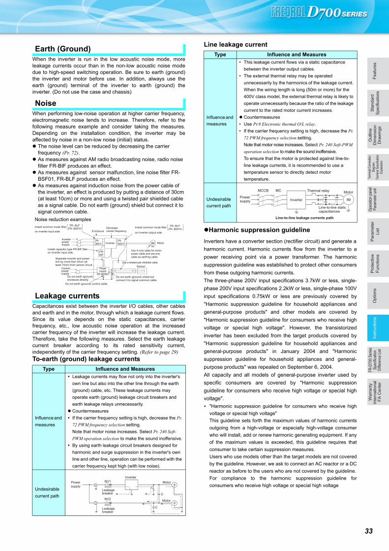
Fe
atu
res
Op
tio
ns
Sta
nd
ard
Speci
ficatio
ns
Pa
ram
ete
r
Lis
t
Pro
tective
Fu
nctio
ns
Term
inal
Con
nect
ion
Dia
gram
Term
inal
Spe
cific
atio
nEx
plan
atio
n
Ou
tlin
eD
ime
nsio
nD
raw
ing
sIn
str
uctio
ns
FR
-D70
0 S
erie
sS
peci
ficat
ion
Diff
eren
ce L
ist
Wa
rra
nty
Inte
rna
tio
na
l F
A C
en
ter
Ope
ratio
n pa
nel
Par
amet
er u
nit
When the inverter is run in the low acoustic noise mode, moreleakage currents occur than in the non-low acoustic noise modedue to high-speed switching operation. Be sure to earth (ground)the inverter and motor before use. In addition, always use theearth (ground) terminal of the inverter to earth (ground) theinverter. (Do not use the case and chassis)
When performing low-noise operation at higher carrier frequency,electromagnetic noise tends to increase. Therefore, refer to thefollowing measure example and consider taking the measures.Depending on the installation condition, the inverter may beaffected by noise in a non-low noise (initial) status. The noise level can be reduced by decreasing the carrier
frequency (Pr. 72). As measures against AM radio broadcasting noise, radio noise
filter FR-BIF produces an effect. As measures against sensor malfunction, line noise filter FR-
BSF01, FR-BLF produces an effect. As measures against induction noise from the power cable of
the inverter, an effect is produced by putting a distance of 30cm (at least 10cm) or more and using a twisted pair shielded cable as a signal cable. Do not earth (ground) shield but connect it to signal common cable.
Capacitances exist between the inverter I/O cables, other cablesand earth and in the motor, through which a leakage current flows.Since its value depends on the static capacitances, carrierfrequency, etc., low acoustic noise operation at the increasedcarrier frequency of the inverter will increase the leakage current.Therefore, take the following measures. Select the earth leakagecurrent breaker according to its rated sensitivity current,independently of the carrier frequency setting. (Refer to page 29)
To-earth (ground) leakage currents
Line leakage current
Harmonic suppression guideline
Inverters have a converter section (rectifier circuit) and generate a
harmonic current. Harmonic currents flow from the inverter to a
power receiving point via a power transformer. The harmonic
suppression guideline was established to protect other consumers
from these outgoing harmonic currents.
The three-phase 200V input specifications 3.7kW or less, single-
phase 200V input specifications 2.2kW or less, single-phase 100V
input specifications 0.75kW or less are previously covered by
"Harmonic suppression guideline for household appliances and
general-purpose products" and other models are covered by
"Harmonic suppression guideline for consumers who receive high
voltage or special high voltage". However, the transistorized
inverter has been excluded from the target products covered by
"Harmonic suppression guideline for household appliances and
general-purpose products" in January 2004 and "Harmonic
suppression guideline for household appliances and general-
purpose products" was repealed on September 6, 2004.
All capacity and all models of general-purpose inverter used by
specific consumers are covered by "Harmonic suppression
guideline for consumers who receive high voltage or special high
voltage".
"Harmonic suppression guideline for consumers who receive high
voltage or special high voltage"
This guideline sets forth the maximum values of harmonic currents
outgoing from a high-voltage or especially high-voltage consumer
who will install, add or renew harmonic generating equipment. If any
of the maximum values is exceeded, this guideline requires that
consumer to take certain suppression measures.
Users who use models other than the target models are not covered
by the guideline. However, we ask to connect an AC reactor or a DC
reactor as before to the users who are not covered by the guideline.
For compliance to the harmonic suppression guideline for
consumers who receive high voltage or special high voltage
Earth (Ground)
Noise
Leakage currents
Type Influence and Measures
Influence and
measures
Leakage currents may flow not only into the inverter's
own line but also into the other line through the earth
(ground) cable, etc. These leakage currents may
operate earth (ground) leakage circuit breakers and
earth leakage relays unnecessarily.
Countermeasures
If the carrier frequency setting is high, decrease the Pr.
72 PWM frequency selection setting.
Note that motor noise increases. Select Pr. 240 Soft-
PWM operation selection to make the sound inoffensive.
By using earth leakage circuit breakers designed for
harmonic and surge suppression in the inverter's own
line and other line, operation can be performed with the
carrier frequency kept high (with low noise).
Undesirable
current path
Inverter
Sensor
Use 4-core cable for motor
power cable and use one
cable as earthing cable.
Use a twisted pair shielded cable
Inverterpowersupply
Controlpowersupply
Do not earth (ground) shield but
connect it to signal common cable.
Enclosure
Decrease
carrier frequency
MotorIMFR-
BSF01
FR-
BSF01
FR-
BIF
Do not earth (ground)
enclosure directly.
Do not earth (ground) control cable.
Separate inverter and power
line by more than 30cm (at
least 10cm) from sensor circuit.
Install common mode filter
on inverter output side.
FR- BLF
FR- BSF01
Install capacitor type FR-BIF filter
on inverter input side.
Install common mode filter
on inverter input side.
FR- BLF
FR- BSF01
Powersupply
for sensor
Noise reduction examples
Power
supplyLeakage breaker
Leakage breaker
NV1
NV2
Inverter
Motor
Motor
C
C
C
Type Influence and Measures
Influence and
measures
• This leakage current flows via a static capacitance
between the inverter output cables.
• The external thermal relay may be operated
unnecessarily by the harmonics of the leakage current.
When the wiring length is long (50m or more) for the
400V class model, the external thermal relay is likely to
operate unnecessarily because the ratio of the leakage
current to the rated motor current increases.
Countermeasures
• Use Pr.9 Electronic thermal O/L relay.
• If the carrier frequency setting is high, decrease the Pr.
72 PWM frequency selection setting.
Note that motor noise increases. Select Pr. 240 Soft-PWM
operation selection to make the sound inoffensive.
To ensure that the motor is protected against line-to-
line leakage currents, it is recommended to use a
temperature sensor to directly detect motor
temperature.
Undesirable
current path
Powersupply
Thermal relay
Line-to-line staticcapacitances
MCCB MC
Line-to-line leakage currents path
Motor
Inverter IM
33
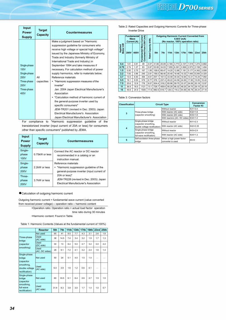
34
For compliance to "Harmonic suppression guideline of the
transistorized inverter (input current of 20A or less) for consumers
other than specific consumers" published by JEMA.
Calculation of outgoing harmonic current
Input
Power
Supply
Target
CapacityCountermeasures
Single-phase
100V
Single-phase
200V
Three-phase
200V
Three-phase
400V
All
capacities
Make a judgment based on "Harmonic
suppression guideline for consumers who
receive high voltage or special high voltage"
issued by the Japanese Ministry of Economy,
Trade and Industry (formerly Ministry of
International Trade and Industry) in
September 1994 and take measures if
necessary. For calculation method of power
supply harmonics, refer to materials below.
Reference materials
"Harmonic suppression measures of the
inverter"
Jan. 2004 Japan Electrical Manufacturer's
Association
"Calculation method of harmonic current of
the general-purpose inverter used by
specific consumers"
JEM-TR201 (revised in Dec. 2003): Japan
Electrical Manufacturer's Association
Japan Electrical Manufacturer's Association
Input
Power
Supply
Target
CapacityCountermeasures
Single-
phase
100V
0.75kW or lessConnect the AC reactor or DC reactor
recommended in a catalog or an
instruction manual.
Reference materials
"Harmonic suppression guideline of the
general-purpose inverter (input current of
20A or less)"
JEM-TR226 (revised in Dec. 2003): Japan
Electrical Manufacturer's Association
Single-
phase
200V
2.2kW or less
Three-
phase
200V
3.7kW or less
Outgoing harmonic current = fundamental wave current (value converted
from received power voltage) operation ratio harmonic content
Operation ratio: Operation ratio = actual load factor operation
time ratio during 30 minutes
Harmonic content: Found in Table.
Table 1: Harmonic Contents (Values at the fundamental current of 100%)
Reactor 5th 7th 11th 13th 17th 19th 23rd 25th
Three-phase
bridge
(capacitor
smoothing)
Not used 65 41 8.5 7.7 4.3 3.1 2.6 1.8
Used(AC side)
38 14.5 7.4 3.4 3.2 1.9 1.7 1.3
Used(DC side)
30 13 8.4 5.0 4.7 3.2 3.0 2.2
Used(AC, DC sides)
28 9.1 7.2 4.1 3.2 2.4 1.6 1.4
Single-phase
bridge
(capacitor
smoothing,
double voltage
rectification)
Not used 50 24 5.1 4.0 1.5 1.4
Used(AC side)
6.0 3.9 1.6 1.2 0.6 0.1
Single-phase bridge(capacitor smoothing, full-wave rectification)
Not used 60 33.5 6.1 6.4 2.6 2.7 1.5 1.5
Used(AC side)
31.9 8.3 3.8 3.0 1.7 1.4 1.0 0.7
Table 2: Rated Capacities and Outgoing Harmonic Currents for Three-phase
Inverter Drive
Ap
plie
dM
oto
r k
W
Fundamental Wave
Current (A)
Fund
amen
tal W
ave
Cur
rent
Con
vert
ed fr
om 6
.6kV
(mA
)
Rat
ed C
apac
ity (k
VA)
Outgoing Harmonic Current Converted from 6.6kV (mA)
(No reactor, 100% operation ratio)
200V 400V 5th 7th 11th 13th 17th 19th 23rd 25th
0.4 1.61 0.81 49 0.57 31.85 20.09 4.165 3.773 2.107 1.519 1.274 0.882
0.75 2.74 1.37 83 0.97 53.95 34.03 7.055 6.391 3.569 2.573 2.158 1.494
1.5 5.50 2.75 167 1.95 108.6 68.47 14.20 12.86 7.181 5.177 4.342 3.006
2.2 7.93 3.96 240 2.81 156.0 98.40 20.40 18.48 10.32 7.440 6.240 4.320
3.7 13.0 6.50 394 4.61 257.1 161.5 33.49 30.34 16.94 12.21 10.24 7.092
5.5 19.1 9.55 579 6.77 376.1 237.4 49.22 44.58 24.90 17.95 15.05 10.42
7.5 25.6 12.8 776 9.07 504.4 318.2 65.96 59.75 33.37 24.06 20.18 13.97
11 36.9 18.5 1121 13.1 728.7 459.6 95.29 86.32 48.20 34.75 29.15 20.18
15 49.8 24.9 1509 17.6 980.9 618.7 128.3 116.2 64.89 46.78 39.24 27.16
Table 3: Conversion factors
Classification Circuit TypeConversion
Factor Ki
3Three-phase bridge (capacitor smoothing)
Without reactor K31=3.4
With reactor (AC side) K32=1.8
With reactor (DC side) K33=1.8
With reactors (AC, DC sides) K34=1.4
4
Single-phase bridge(capacitor smoothing, double voltage rectification)
Without reactor K41=2.3
With reactor (AC side) K42=0.35
Single-phase bridge(capacitor smoothing, full-wave rectification)
Without reactor K43=2.9
With reactor (AC side) K44=1.3
5Self-excitation three-phase bridge
When a high power factor converter is used
K5=0

Fe
atu
res
Op
tio
ns
Sta
nd
ard
Speci
ficatio
ns
Pa
ram
ete
r
Lis
t
Pro
tective
Fu
nctio
ns
Term
inal
Con
nect
ion
Dia
gram
Term
inal
Spe
cific
atio
nEx
plan
atio
n
Ou
tlin
eD
ime
nsio
nD
raw
ing
sIn
str
uctio
ns
FR
-D70
0 S
erie
sS
peci
ficat
ion
Diff
eren
ce L
ist
Wa
rra
nty
Inte
rna
tio
na
l F
A C
en
ter
Ope
ratio
n pa
nel
Par
amet
er u
nit
35
Item Japanese Specification NA Specification EC Specification CHT Specification
Applicable Capacity
Type
FR-D720-0.1K to 15KFR-D740-0.4K to 15KFR-D720S-0.1K to 2.2KFR-D710W-0.1K to 0.75KType : Rated capacity (kW)
FR-D720-008 to 318-NAFR-D740-012 to 160-NAFR-D720S-008 to 100-NAFR-D710W-008 to 042-NAType : Rated current value
FR-D740-012 to 160-ECFR-D720S-008 to 100-ECType : Rated current value
FR-D740-0.4K to 7.5K-CHTFR-D720S-0.1K to 2.2K-CHTType : Rated capacity (kW)
Main Circuit Terminal
NameR, S, T L1, L2, L3
AC Power InputThree-phase InputSingle-phase Input R, S L1, N
Brake Unit
ConnectionP, N +, -
Control Terminal Logic
Initial SettingSink logic Sink logic Source logic Sink logic
Control Terminal
Contact Input Common
Terminal
Initial Setting
SD SD PC SD
Monitor Output
Terminal For IndicatorFM (Digital output) AM (Analog output) AM (Analog output) AM (Analog output)
Parameter
60Hz 60Hz 50Hz 50Hz
Pr.3, Pr.4, Pr.20,Pr.55, Pr.66, Pr.84,
Pr.125, Pr.126, Pr.903, Pr.905, Pr.923Initial Value
Pr.19 Initial Value 9999 9999 8888 9999
Pr.122 Initial Value 0 9999 9999 0
Pr.145 Initial Value 0 1 1 1
Pr.160 Initial Value 9999 0 0 9999
Pr.249 Initial Value 0 0 1 1
Indicator Output
Terminal Function
Pr.54 FM terminal function selection,
Pr.900 FM terminal calibration
Pr.158 AM terminal function selection,
Pr.901 AM terminal calibration
Pr.158 AM terminal function selection,
Pr.901 AM terminal calibration
Pr.158 AM terminal function selection,
Pr.901 AM terminal calibration
Traverse Function
Pr.592 to Pr.597Without Without With With
FR-D700 Series Specification Difference List

36
Warranty
When using this product, make sure to understand the warranty described below.
1. Warranty period and coverage
We will repair any failure or defect (hereinafter referred to as "failure") in our FA equipment (hereinafter referred to as the "Product") arisen during warranty period at no charge due to causes for which we are responsible through the distributor from which you purchased the Product or our service provider. However, we will charge the actual cost of dispatching our engineer for an on-site repair work on request by customer in Japan or overseas countries. We are not responsible for any on-site readjustment and/or trial run that may be required after a defective unit are repaired or replaced.
[Term]The term of warranty for Product is twelve months after your purchase or delivery of the Product to a place designated by you or eighteen months from the date of manufacture whichever comes first ("Warranty Period"). Warranty period for repaired Product cannot exceed beyond the original warranty period before any repair work.
[Limitations](1) You are requested to conduct an initial failure diagnosis by yourself, as a general rule. It can also be carried out by us or our
service company upon your request and the actual cost will be charged.However, it will not be charged if we are responsible for the cause of the failure.
(2) This limited warranty applies only when the condition, method, environment, etc. of use are in compliance with the terms and conditions and instructions that are set forth in the instruction manual and user manual for the Product and the caution label affixed to the Product.
(3) Even during the term of warranty, the repair cost will be charged on you in the following cases;1) a failure caused by your improper storing or handling, carelessness or negligence, etc., and a failure caused by your hardware
or software problem2) a failure caused by any alteration, etc. to the Product made on your side without our approval3) a failure which may be regarded as avoidable, if your equipment in which the Product is incorporated is equipped with a safety
device required by applicable laws and has any function or structure considered to be indispensable according to a common sense in the industry
4) a failure which may be regarded as avoidable if consumable parts designated in the instruction manual, etc. are duly maintained and replaced
5) any replacement of consumable parts (condenser, cooling fan, etc.)6) a failure caused by external factors such as inevitable accidents, including without limitation fire and abnormal fluctuation of
voltage, and acts of God, including without limitation earthquake, lightning and natural disasters7) a failure generated by an unforeseeable cause with a scientific technology that was not available at the time of the shipment of
the Product from our company8) any other failures which we are not responsible for or which you acknowledge we are not responsible for
2. Term of warranty after the stop of production(1) We may accept the repair at charge for another seven (7) years after the production of the product is discontinued. The
announcement of the stop of production for each model can be seen in our Sales and Service, etc.(2) Please note that the Product (including its spare parts) cannot be ordered after its stop of production.
3. Service in overseasOur regional FA Center in overseas countries will accept the repair work of the Product; however, the terms and conditions of the repair work may differ depending on each FA Center. Please ask your local FA center for details.
4. Exclusion of loss in opportunity and secondary loss from warranty liabilityRegardless of the gratis warranty term, Mitsubishi shall not be liable for compensation to:(1) Damages caused by any cause found not to be the responsibility of Mitsubishi.(2) Loss in opportunity, lost profits incurred to the user by Failures of Mitsubishi products.(3) Special damages and secondary damages whether foreseeable or not, compensation for accidents, and compensation for
damages to products other than Mitsubishi products.(4) Replacement by the user, maintenance of on-site equipment, start-up test run and other tasks.
5. Change of Product specificationsSpecifications listed in our catalogs, manuals or technical documents may be changed without notice.
6. Application and use of the Product(1) For the use of our product, its applications should be those that may not result in a serious damage even if any failure or
malfunction occurs in product, and a backup or fail-safe function should operate on an external system to product when any failure or malfunction occurs.
(2) Our product is designed and manufactured as a general purpose product for use at general industries.Therefore, applications substantially influential on the public interest for such as atomic power plants and other power plants of electric power companies, and also which require a special quality assurance system, including applications for railway companies and government or public offices are not recommended, and we assume no responsibility for any failure caused by these applications when used.In addition, applications which may be substantially influential to human lives or properties for such as airlines, medical treatments, railway service, incineration and fuel systems, man-operated material handling equipment, entertainment machines, safety machines, etc. are not recommended, and we assume no responsibility for any failure caused by these applications when used.We will review the acceptability of the abovementioned applications, if you agree not to require a specific quality for a specific application. Please contact us for consultation.

MEMO
Fe
atu
res
Op
tio
ns
Sta
nd
ard
Speci
ficatio
ns
Pa
ram
ete
r
Lis
t
Pro
tective
Fu
nctio
ns
Term
inal
Con
nect
ion
Dia
gram
Term
inal
Spe
cific
atio
nEx
plan
atio
n
Ou
tlin
eD
ime
nsio
nD
raw
ing
sIn
str
uctio
ns
FR
-D70
0 S
erie
sS
peci
ficat
ion
Diff
eren
ce L
ist
Wa
rra
nty
Inte
rna
tio
na
l F
A C
en
ter
Ope
ratio
n pa
nel
Par
amet
er u
nit
37
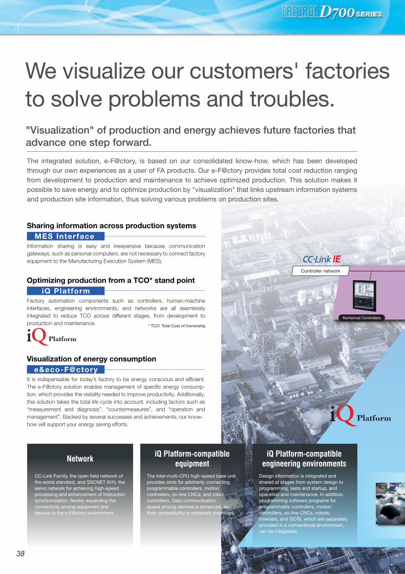
"Visualization"by information
linkage
Operation andplanning system
Information system
Production site
Robots Safety Controllers Motion Controllers
AC Servo
Programmable Controllers Electrical-Discharge Machines Laser Processing Machines
ERP
Ethernet
Products for achieving e-F@ctory
B/NET
Foolproofterminal
Mapping sensorterminal
Manufacturing execution systemMES
Information network
Safety field network Field network
Sensor network
Field network
Field network
Servo-network
Reduced wiring network
Safety remote I/O Energymeasurement unit
MDUbreaker
Electronic multi-indicatinginstrument
Remote I/O
ProgrammableControllers
Geared motor Robots
MES linkage functionMES linkage function
Diagnosis unit with MES Interface (MELQIC) HMI with MES Interface Programmable Controllers with MES Interface EcoServer III
Numerical Controllers
Controller network
CC-Link-AnyWireBitty Bridge
We visualize our customers' factories to solve problems and troubles."Visualization" of production and energy achieves future factories that advance one step forward.
The integrated solution, e-F@ctory, is based on our consolidated know-how, which has been developed through our own experiences as a user of FA products. Our e-F@ctory provides total cost reduction ranging from development to production and maintenance to achieve optimized production. This solution makes it possible to save energy and to optimize production by "visualization" that links upstream information systems and production site information, thus solving various problems on production sites.
Sharing information across production systems
Information sharing is easy and inexpensive because communication gateways, such as personal computers, are not necessary to connect factory equipment to the Manufacturing Execution System (MES).
* TCO: Total Cost of Ownership
MES Interface
Optimizing production from a TCO* stand point
Factory automation components such as controllers, human-machine interfaces, engineering environments, and networks are all seamlessly integrated to reduce TCO across different stages, from development to production and maintenance.
iQ Platform
Visualization of energy consumption
It is indispensable for today’s factory to be energy conscious and efficient. The e-F@ctory solution enables management of specific energy consump-tion, which provides the visibility needed to improve productivity. Additionally, this solution takes the total life cycle into account, including factors such as “measurement and diagnosis”, “countermeasures”, and “operation and management”. Backed by several successes and achievements, our know-how will support your energy saving efforts.
e&eco-F@ctory
iQ Platform-compatibleequipment
Design information is integrated and shared at stages from system design to programming, tests and startup, and operation and maintenance. In addition, programming software programs for programmable controllers, motion controllers, on-line CNCs, robots, inverters, and GOTs, which are separately provided in a conventional environment, can be integrated.
The inter-multi-CPU high-speed base unit provides slots for arbitrarily connecting programmable controllers, motion controllers, on-line CNCs, and robot controllers. Data communicationspeed among devices is enhanced, and their compatibility is extremely improved.
CC-Link Family, the open field network of the world standard, and SSCNET III/H, the servo network for achieving high-speed processing and enhancement of instruction synchronization, flexibly expanding the connectivity among equipment and devices in the e-F@ctory environment.
iQ Platform-compatibleengineering environmentsNetwork
Inverter
3938
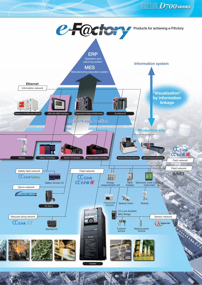

4140

4140
MEMO YOUR SOLUTION PARTNER
Mitsubishi Electric offers a wide range of automation equipment from PLCs and HMIs to
CNC and EDM machines.
* Not all products are available in all countries.
A NAME TO TRUSTSince its beginnings in 1870, some45 companies use the Mitsubishiname, covering a spectrum offinance, commerce and industry.
The Mitsubishi brand name isrecognized around the world as asymbol of premium quality.
Mitsubishi Electric Corporation isactive in space development,transportation, semi-conductors,energy systems, communicationsand information processing, audiovisual equipment and homeelectronics, building and energymanagement and automationsystems, and has 237 factories andlaboratories worldwide in over 121countries.
This is why you can rely onMitsubishi Electric automationsolution - because we know firsthand about the need for reliable,efficient, easy-to-use automation andcontrol in our own factories.
As one of the world’s leadingcompanies with a global turnover ofover 4 trillion Yen (over $40 billion),employing over 100,000 people,Mitsubishi Electric has the resourceand the commitment to deliver theultimate in service and support aswell as the best products.
High-voltage Circuit Breakers, High-voltage Contactors
Energy Saving Supporting Devices, Power Monitoring Products
Programmable Controllers, HMIs (Human-Machine Interfaces)
AC Servos, Three-phase Motors, IPM Motors Inverters, Geared Motors
Computerized Numerical Controllers (CNCs)
Industrial Robots
Electrical Discharge Machines, Laser Processing Machines, Electron Beam Machines
Distribution Transformers
Pressurized Ventilation Fans, Uninterruptible Power Supplies
Low-voltage Circuit Breakers, Motor Starters
•Trademarks
MODBUS is a registered trademark of SCHNEIDER ELECTRIC USA, INC.
Ethernet is a registered trademark of Fuji Xerox Corporation in Japan.
Windows and Windows Vista are registered trademarks of Microsoft Corporation in the United States
and other countries.
Other company and product names herein are the trademarks and registered trademarks of their
respective owners.
To ensure proper use of the products listed in this catalog, please be sure to read the instruction manual prior to use.
Safety Warning
4342
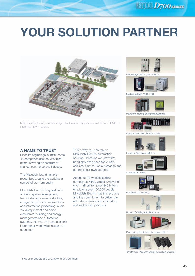
MEMO
•Trademarks
MODBUS is a registered trademark of SCHNEIDER ELECTRIC USA, INC.
Ethernet is a registered trademark of Fuji Xerox Corporation in Japan.
Windows and Windows Vista are registered trademarks of Microsoft Corporation in the United States
and other countries.
Other company and product names herein are the trademarks and registered trademarks of their
respective owners.
To ensure proper use of the products listed in this catalog, please be sure to read the instruction manual prior to use.
Safety Warning
YOUR SOLUTION PARTNER
Mitsubishi Electric offers a wide range of automation equipment from PLCs and HMIs to
CNC and EDM machines.
A NAME TO TRUSTSince its beginnings in 1870, some 45 companies use the Mitsubishi name, covering a spectrum of finance, commerce and industry.
The Mitsubishi brand name is recognized around the world as a symbol of premium quality.
Mitsubishi Electric Corporation is active in space development, transportation, semi-conductors, energy systems, communications and information processing, audio visual equipment and home electronics, building and energy management and automation systems, and has 237 factories and laboratories worldwide in over 121 countries.
This is why you can rely on Mitsubishi Electric automation solution - because we know first hand about the need for reliable, efficient, easy-to-use automation and control in our own factories.
As one of the world’s leading companies with a global turnover of over 4 trillion Yen (over $40 billion), employing over 100,000 people, Mitsubishi Electric has the resource and the commitment to deliver the ultimate in service and support as well as the best products.
Medium voltage: VCB, VCC
Power monitoring, energy management
Compact and Modular Controllers
Inverters, Servos and Motors
Visualisation: HMIs
Numerical Control (NC)
Robots: SCARA, Articulated arm
Processing machines: EDM, Lasers, IDS
Transformers, Air conditioning, Photovoltaic systems
Low voltage: MCCB, MCB, ACB
* Not all products are available in all countries.
4342

L(NA)06055ENG-H(1803)MEE
HEAD OFFICE: TOKYO BLDG., 2-7-3, MARUNOUCHI, CHIYODA-KU, TOKYO 100-8310, JAPAN
Mitsubishi Electric Corporation Nagoya Works is a factory certified for ISO14001 (standards for environmental management systems)and ISO9001(standards for quality assurance management systems)
• Pursuing the easy operation
• Long life and simple maintenance
• Compact and space-saving
• Supporting various applications
INVERTERFR-D700Global standard
FACTORY AUTOMATION