Facilities United States Department of Agriculture · June 2008 Facilities T For additional...
8
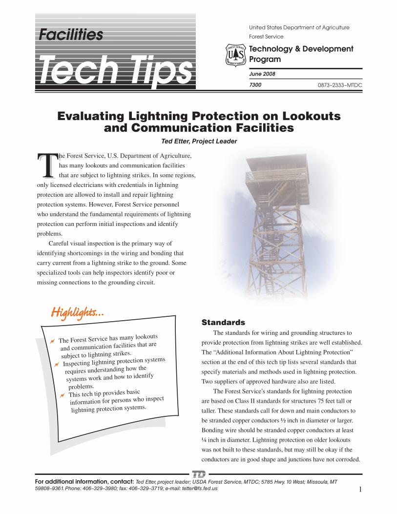
1 The Forest Service has many lookouts and communication facilities that are subject to lightning strikes. Inspecting lightning protection systems requires understanding how the systems work and how to identify problems. This tech tip provides basic information for persons who inspect lightning protection systems. Technology & Development Program United States Department of Agriculture Forest Service June 2008 Facilities T For additional information, contact: Ted Etter, project leader; USDA Forest Service, MTDC; 5785 Hwy. 10 West; Missoula, MT 59808–9361. Phone: 406–329–3980; fax: 406–329–3719; e-mail: [email protected] Evaluating Lightning Protection on Lookouts and Communication Facilities Ted Etter, Project Leader 7300 0873–2333–MTDC T he Forest Service, U.S. Department of Agriculture, has many lookouts and communication facilities that are subject to lightning strikes. In some regions, only licensed electricians with credentials in lightning protection are allowed to install and repair lightning protection systems. However, Forest Service personnel who understand the fundamental requirements of lightning protection can perform initial inspections and identify problems. Careful visual inspection is the primary way of identifying shortcomings in the wiring and bonding that carry current from a lightning strike to the ground. Some specialized tools can help inspectors identify poor or missing connections to the grounding circuit. Standards The standards for wiring and grounding structures to provide protection from lightning strikes are well established. The “Additional Information About Lightning Protection” section at the end of this tech tip lists several standards that specify materials and methods used in lightning protection. Two suppliers of approved hardware also are listed. The Forest Service’s standards for lightning protection are based on Class II standards for structures 75 feet tall or taller. These standards call for down and main conductors to be stranded copper conductors ½ inch in diameter or larger. Bonding wire should be stranded copper conductors at least ¼ inch in diameter. Lightning protection on older lookouts was not built to these standards, but may still be okay if the conductors are in good shape and junctions have not corroded.
Transcript of Facilities United States Department of Agriculture · June 2008 Facilities T For additional...
1
� The Forest Service has many lookouts
and communication facilities that are
subject to lightning strikes.
� Inspecting lightning protection systems
requires understanding how the
systems work and how to identify
problems.
� This tech tip provides basic
information for persons who inspect
lightning protection systems.
Technology & Development Program
United States Department of Agriculture
Forest Service
June 2008
Facilities
T
For additional information, contact: Ted Etter, project leader; USDA Forest Service, MTDC; 5785 Hwy. 10 West; Missoula, MT 59808–9361. Phone: 406–329–3980; fax: 406–329–3719; e-mail: [email protected]
Evaluating Lightning Protection on Lookouts and Communication Facilities
Ted Etter, Project Leader
7300 0873–2333–MTDC
The Forest Service, U.S. Department of Agriculture,
has many lookouts and communication facilities
that are subject to lightning strikes. In some regions,
only licensed electricians with credentials in lightning
protection are allowed to install and repair lightning
protection systems. However, Forest Service personnel
who understand the fundamental requirements of lightning
protection can perform initial inspections and identify
problems.
Careful visual inspection is the primary way of
identifying shortcomings in the wiring and bonding that
carry current from a lightning strike to the ground. Some
specialized tools can help inspectors identify poor or
missing connections to the grounding circuit.
StandardsThe standards for wiring and grounding structures to
provide protection from lightning strikes are well established.
The “Additional Information About Lightning Protection”
section at the end of this tech tip lists several standards that
specify materials and methods used in lightning protection.
Two suppliers of approved hardware also are listed.
The Forest Service’s standards for lightning protection
are based on Class II standards for structures 75 feet tall or
taller. These standards call for down and main conductors to
be stranded copper conductors ½ inch in diameter or larger.
Bonding wire should be stranded copper conductors at least
¼ inch in diameter. Lightning protection on older lookouts
was not built to these standards, but may still be okay if the
conductors are in good shape and junctions have not corroded.
2
Basics of Lightning Protection Systems
A lightning protection system protects the occupants and
contents of a structure from the potential harm of a lightning
strike. Lightning is a brief surge of electrical current that
reduces the voltage difference between the earth and an
electrical charge that has accumulated in the atmosphere. Air
terminals, main conductors, and ground rods or radials are
the primary components of a lightning protection system.
They provide a favored path for the electrical current of a
lightning strike around the structure, preventing the current
from passing through occupants and equipment. Additional
wiring serves to shield interior spaces. Surge arresters reduce
the likelihood of damage to electrical hardware inside the
structure.
Air terminals atop a structure must be connected to
grounding rods or radials with large-gauge wire. Permanent
metal objects around and within the structure must be
electrically bonded to the ground wiring. In essence, a wire
box outlines the structure, shielding persons and equipment
inside, in the event of a lightning strike. Through age,
negligence, or vandalism, a structure’s protective wiring
may not ensure protection for the occupants. Careful visual
inspection is the primary way of identifying shortcomings
in ground wiring and bonding. Such inspections should be
performed annually, especially before a structure is first
occupied for the season.
The following fundamental standards are typical for
inspection of lightning protection at a Forest Service lookout:
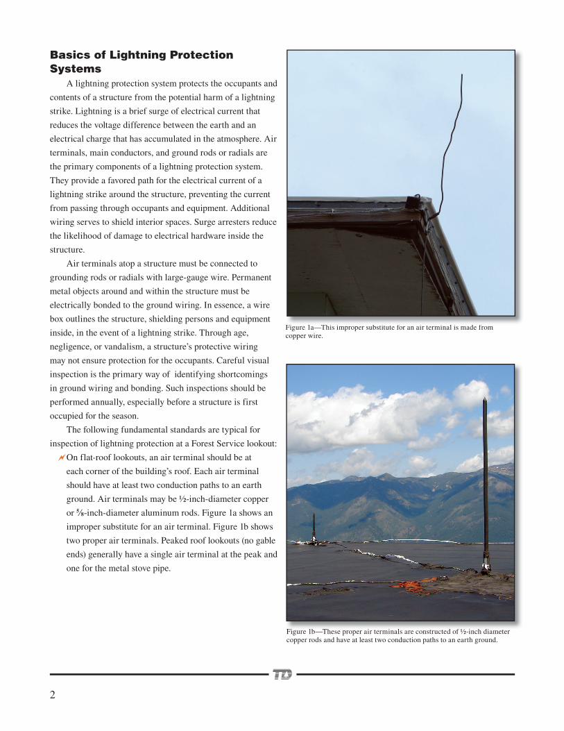
On flat-roof lookouts, an air terminal should be at
each corner of the building’s roof. Each air terminal
should have at least two conduction paths to an earth
ground. Air terminals may be ½ -inch-diameter copper
or 5⁄8-inch-diameter aluminum rods. Figure 1a shows an
improper substitute for an air terminal. Figure 1b shows
two proper air terminals. Peaked roof lookouts (no gable
ends) generally have a single air terminal at the peak and
one for the metal stove pipe.
Figure 1a—This improper substitute for an air terminal is made from copper wire.
i hi i b i f i i l i d f
Figure 1b—These proper air terminals are constructed of ½ -inch diameter copper rods and have at least two conduction paths to an earth ground.Fi 1b Th i i l d f ½ i h di
3
Main conductors that connect air terminals to ground
rods or radials should be stranded copper wire ½ inch in
diameter or larger.
The minimum bend radius of main conductors is 8
inches (to prevent electrical induction).
Radio coaxial cables, telephone cables, and power cables
from outside the structure must pass through bonded
surge arresters when bringing signals or supply voltages
inside the structure.
Metal items that should be bonded to main conductors
include window frames, wire mesh on railings, stoves,
propane tanks, radio antennas, guy wires, solar panels,
and battery banks, to name a few.
Bonding wire should be stranded copper conductor ¼
inch in diameter or larger.
Down conductors (main conductors taking current down
to the earth ground) should be attached to ground rods,
ground plates, or radial wire networks.
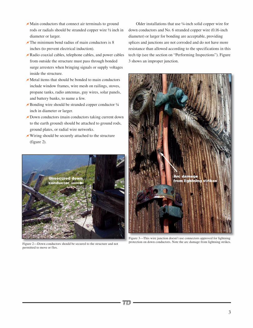
Wiring should be securely attached to the structure
(figure 2).
Figure 3—This wire junction doesn’t use connectors approved for lightning protection on down conductors. Note the arc damage from lightning strikes.
Older installations that use ¼ -inch solid copper wire for
down conductors and No. 6 stranded copper wire (0.16-inch
diameter) or larger for bonding are acceptable, providing
splices and junctions are not corroded and do not have more
resistance than allowed according to the specifications in this
tech tip (see the section on “Performing Inspections”). Figure
3 shows an improper junction.
Figure 2—Down conductors should be secured to the structure and not permitted to move or flex.
i 2 d h ld b d h d
4
Copper is the conductor of choice for connecting the
components of a lightning protection system. While silver is
a better conductor than copper, it costs more. Large-gauge
copper wire is used for the main conductors that connect
air terminals (lightning rods usually made of solid copper)
to the grounding network. Smaller gauge wire may be used
to connect metal objects such as window frames and metal
construction hardware to the main conductors. Wiring
connections must use hardware that minimizes electrical
resistance at the junction and that prevents corrosion to
maintain the junction’s low resistance.
BondingOne of the functions of the complete lightning protection
system is to minimize the voltage difference between metal
objects in and around the structure during a lightning strike. For
instance, large voltage differences between a down conductor
and a wood stove inside a cabin can lead to arcs (side flashes)
that may harm occupants and equipment inside the cabin.
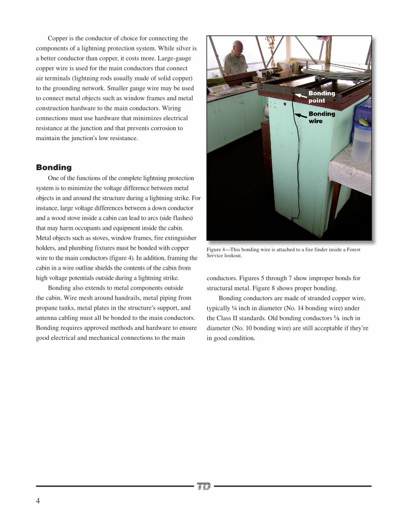
Metal objects such as stoves, window frames, fire extinguisher
holders, and plumbing fixtures must be bonded with copper
wire to the main conductors (figure 4). In addition, framing the
cabin in a wire outline shields the contents of the cabin from
high voltage potentials outside during a lightning strike.
Bonding also extends to metal components outside
the cabin. Wire mesh around handrails, metal piping from
propane tanks, metal plates in the structure’s support, and
antenna cabling must all be bonded to the main conductors.
Bonding requires approved methods and hardware to ensure
good electrical and mechanical connections to the main
conductors. Figures 5 through 7 show improper bonds for
structural metal. Figure 8 shows proper bonding.
Bonding conductors are made of stranded copper wire,
typically ¼ inch in diameter (No. 14 bonding wire) under
the Class II standards. Old bonding conductors 1⁄8 inch in
diameter (No. 10 bonding wire) are still acceptable if they’re
in good condition.
Figure 4—This bonding wire is attached to a fire finder inside a Forest Service lookout.
5
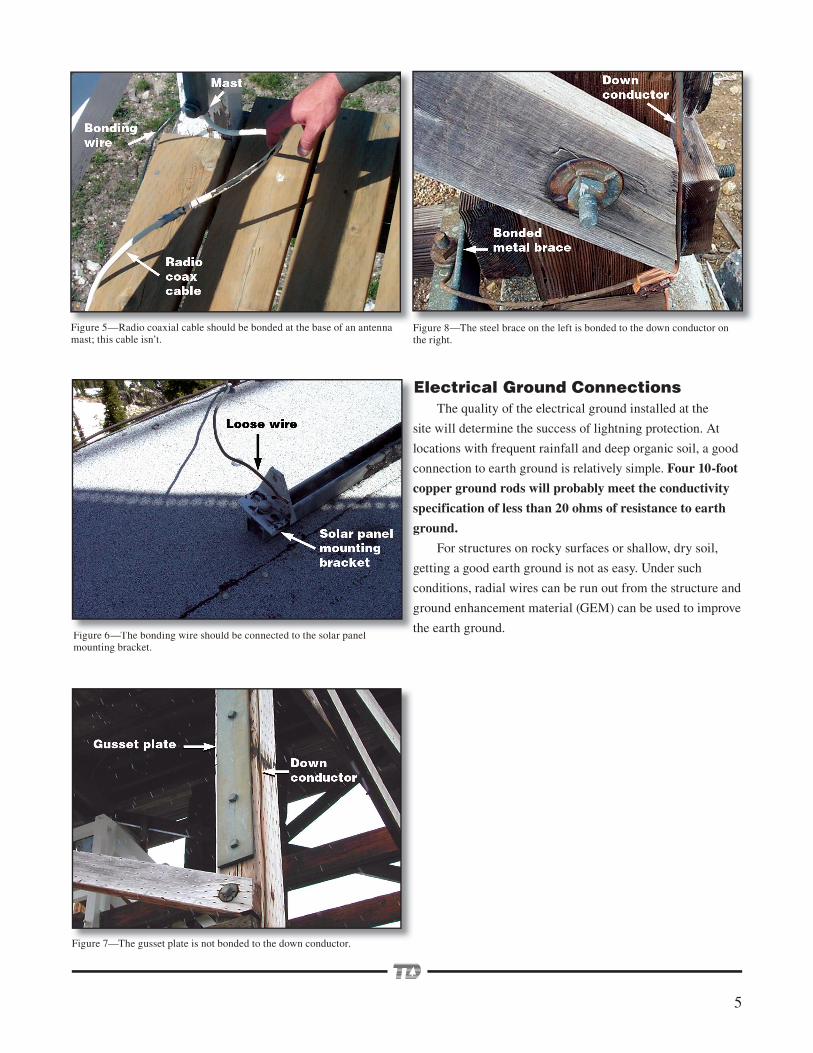
Figure 5—Radio coaxial cable should be bonded at the base of an antenna mast; this cable isn’t.
Figure 8—The steel brace on the left is bonded to the down conductor on the right.
Electrical Ground ConnectionsThe quality of the electrical ground installed at the
site will determine the success of lightning protection. At
locations with frequent rainfall and deep organic soil, a good
connection to earth ground is relatively simple. Four 10-foot
copper ground rods will probably meet the conductivity
specification of less than 20 ohms of resistance to earth
ground.
For structures on rocky surfaces or shallow, dry soil,
getting a good earth ground is not as easy. Under such
conditions, radial wires can be run out from the structure and
ground enhancement material (GEM) can be used to improve
the earth ground.
Figure 7—The gusset plate is not bonded to the down conductor.
Figure 6—The bonding wire should be connected to the solar panel mounting bracket.
E
s
l
c
c
s
g
g
c
g
tFi 6 Th b di i h ld b d h l l
6
Performing InspectionsInspecting lightning protection systems requires
determining whether the specified conductors and
connections exist and whether connections appear to
be mechanically sound and free from corrosion. Many
lookout inspections have found that the main conductors
were physically damaged or had been removed entirely.
A common fault is the failure to bond metal items in and
around the cabin to the main conductors.
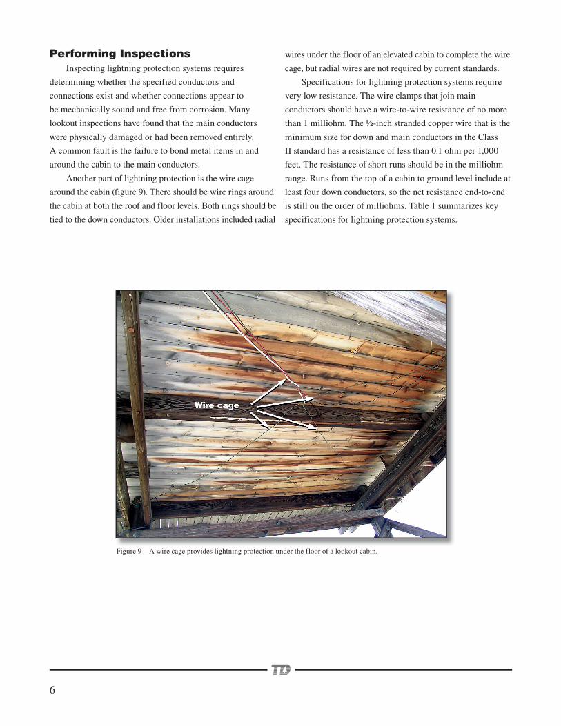
Another part of lightning protection is the wire cage
around the cabin (figure 9). There should be wire rings around
the cabin at both the roof and floor levels. Both rings should be
tied to the down conductors. Older installations included radial
wires under the floor of an elevated cabin to complete the wire
cage, but radial wires are not required by current standards.
Specifications for lightning protection systems require
very low resistance. The wire clamps that join main
conductors should have a wire-to-wire resistance of no more
than 1 milliohm. The ½ -inch stranded copper wire that is the
minimum size for down and main conductors in the Class
II standard has a resistance of less than 0.1 ohm per 1,000
feet. The resistance of short runs should be in the milliohm
range. Runs from the top of a cabin to ground level include at
least four down conductors, so the net resistance end-to-end
is still on the order of milliohms. Table 1 summarizes key
specifications for lightning protection systems.
Figure 9—A wire cage provides lightning protection under the floor of a lookout cabin.
7
The low resistances and multiple paths for current in the
protection network challenge the capabilities of conventional
ohmmeters or multimeters to evaluate the quality of the
wiring. Typical digital multimeters have a resolution of
one tenth of an ohm. Evaluating wire junctions or bonding
connections using such meters should give indications of one
or no counts (tenths of an ohm) above the value indicated
when the meter’s test leads are shorted together.
Conventional ohmmeters can be used to test bonded
items that have only one connection to a main conductor for
a single-circuit junction between an air terminal and a down
conductor. Conventional ohmmeters are less effective for
testing the resistance of a junction including main conductors
because most junctions occur in parallel circuits.
Some measurement tools can be used to test the quality
of the earth ground and the resistance of wire junctions.
Additional tools are being evaluated and developed at the
Missoula Technology and Development Center (MTDC) for
measuring ground resistance on sandy or rocky soils and for
measuring wiring resistance over long runs. Evaluations of
those tools and recommendations for their proper use will be
covered in a future document.
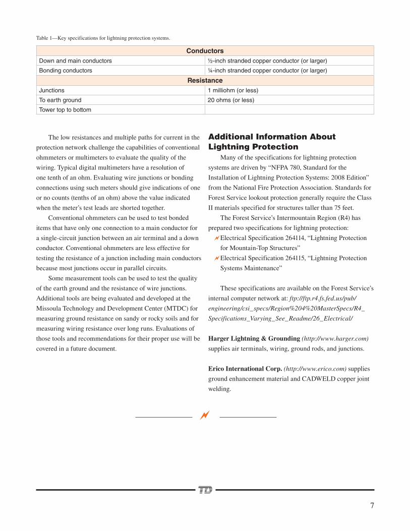
ConductorsDown and main conductors ½ -inch stranded copper conductor (or larger)
Bonding conductors ¼ -inch stranded copper conductor (or larger)
ResistanceJunctions 1 milliohm (or less)
To earth ground 20 ohms (or less)
Tower top to bottom
Table 1—Key specifications for lightning protection systems.
Additional Information About Lightning Protection
Many of the specifications for lightning protection
systems are driven by “NFPA 780, Standard for the
Installation of Lightning Protection Systems: 2008 Edition”
from the National Fire Protection Association. Standards for
Forest Service lookout protection generally require the Class
II materials specified for structures taller than 75 feet.
The Forest Service’s Intermountain Region (R4) has
prepared two specifications for lightning protection:
Electrical Specification 264114, “Lightning Protection
for Mountain-Top Structures”
Electrical Specification 264115, “Lightning Protection
Systems Maintenance”
These specifications are available on the Forest Service’s
internal computer network at: ftp://ftp.r4.fs.fed.us/pub/
engineering/csi_specs/Region%204%20MasterSpecs/R4_
Specifications_Varying_See_Readme/26_Electrical/
Harger Lightning & Grounding (http://www.harger.com)
supplies air terminals, wiring, ground rods, and junctions.
Erico International Corp. (http://www.erico.com) supplies
ground enhancement material and CADWELD copper joint
welding.
8
The Forest Service, United States Department of Agriculture (USDA), has developed this information for the guidance of its employees, its contractors, and its cooperating Federal and State agencies, and is not responsible for the interpretation or use of this information by anyone except its own employees. The use of trade, fi rm, or corporation names in this document is for the information and convenience of the reader, and does not constitute an endorsement by the Department of any product or service to the exclusion of others that may be suitable.
The U.S. Department of Agriculture (USDA) prohibits discrimination in all its programs and activities on the basis of race, color, national origin, age, disability, and where applicable, sex, marital status, familial status, parental status, religion, sexual orientation, genetic information, political beliefs, reprisal, or because all or part of an individual’s income is derived from any public assistance program. (Not all prohibited bases apply to all programs.) Persons with disabilities who require alternative means for communication of program information (Braille, large print, audiotape, etc.) should contact USDA’s TARGET Center at (202) 720-2600 (voice and TDD). To fi le a complaint of discrimination, write to USDA, Director, Offi ce of Civil Rights, 1400 Independence Avenue, S.W., Washington, D.C. 20250-9410, or call (800) 795-3272 (voice) or (202) 720-6382 (TDD). USDA is an equal opportunity provider and employer.
AcknowledgmentsThanks to Shane Brown, Region 4 electrical engineer, for specifications on protection systems and to Steve Oravetz,
Region 1 facility group leader, for lookout tours.
Library Card Etter, Ted. 2008. Evaluating lightning protection on lookouts and communication facilities. Tech Tip 0873–2333–
MTDC. Missoula, MT: U.S. Department of Agriculture Forest Service, Missoula Technology and Development Center. 8 p.
The Forest Service has many lookout towers and communication facilities that are subject to lightning strikes. Inspecting
lightning protection systems at these facilities requires understanding how the systems work and how problems can be
identified. This tech tip provides basic information for persons who inspect lightning protection systems.
Keywords: facilities, grounding, inspections, electrical resistance, safety at work, specifications, wiring
Additional single copies of this document may be ordered
from:
USDA Forest Service
Missoula Technology and Development Center
5785 Hwy. 10 West
Missoula, MT 59808–9361
Phone: 406–329–3978
Fax: 406–329–3719
E-mail: [email protected]
Electronic copies of MTDC’s documents are available on
the Internet at:
http://www.fs.fed.us/eng/t-d.php
For additional information about lightning protection,
contact Ted Etter at MTDC:
Phone: 406–329–3980
Fax: 406–329–3719
E-mail: [email protected]
Forest Service and Bureau of Land Management
employees can search a more complete collection of
MTDC’s documents, CDs, DVDs, and videos on their
internal computer networks at:
http://fsweb.mtdc.wo.fs.fed.us/search/
About the AuthorTed Etter joined MTDC in 2002 as an electronics engineer and project leader. He has 20 years of experience
working for private industry in the design of test equipment, display devices, and medical instrumentation. For 6 years
before he joined MTDC, Ted taught courses in the electronics technology program at the University of Montana College
of Technology, Missoula. His work at MTDC includes projects in wireless communications, alternative energy sources,
instrumentation, and process control. Ted received a bachelor’s degree in mathematics from the University of Oregon and a
master’s degree in teacher education from Eastern Oregon State University.

![Key Elements of NFPA 99 (and the “other” NFPA · [Fires in Healthcare Facilities, NFPA, 11/12] 4 . What We Know about Healthcare Fires ...](https://static.fdocuments.us/doc/165x107/5b318f387f8b9a744a8bddfe/key-elements-of-nfpa-99-and-the-other-nfpa-fires-in-healthcare-facilities.jpg)


![Public Input No. 241-NFPA 780-2017 [ Global Input ] Statement of … · 2018-02-08 · Public Input No. 76-NFPA 780-2017 [ Section No. 1.1.3 ] 1.1.3 This document shall not cover](https://static.fdocuments.us/doc/165x107/5e61af926d38be0fb9104ce1/public-input-no-241-nfpa-780-2017-global-input-statement-of-2018-02-08-public.jpg)