Fabrication Process of 3D Micro Components from Stainless ... · PDF fileMicro system...
5
Abstract— The fabrication process of stainless steel micro components is reported in this work. The process is divided into two parts. In the first part, high quality SU-8 master moulds and their negative replicas from soft moulds are produced using photolithography and soft moulding techniques respectively. The second part includes preparation of stainless steel slurry, filling the soft mould, obtaining the green parts, de-binding and sintering to the finial parts. A proposed method was used in this research to obtain the optimum dispersant used for preparation of the metallic slurry and the result was found to be 0.003wt of the metal powder. Two different sintering conditions were investigated, vacuum and forming gas atmospheres. The results showed high quality micro components the same quality as the master moulds. The maximum sintered density was found to be 98.1% of the theoretical one when the samples were sintered at 1350 ο C in vacuum. Index Terms— dispersant, micro parts, sintering, stainless steel I. INTRODUCTION MEMS components offer a wide range of various applications and their materials have expanded rapidly in recent years. Among the new MEMS materials, metals show many favourable properties. 316-L stainless steel is one of the metallic materials providing good mechanical and corrosion resistance. Recently, many micro fabrication techniques have been emerging to cover a wide range of materials and applications. Micro system technology (MST) is one of the leading technologies of producing micro components ranging from nanometres to millimetres [1]. X-ray Lithography is a conventional micro fabrication technique which is suitable to fabricate polymeric and silicon based materials [2], [3]. Other fabrication techniques; micro electro discharge machining (EDM) and laser micro machining provides a wide range of materials micro components [4], [5]. EDM is limited to conductive materials and laser micro machining produces structures with rough edges. Electroforming is another micro fabrication technique used for producing micro components from metallic materials [6], [7]. Electroforming has a difficulty in Manuscript received February 21, 2009; accepted March 8, 2009. This work was supported by the Ministry of Higher Education in Egypt. M. Imbaby is a member of MicroEngineering and nanoTechnology Group in the Bio-medical & Micro Engineering Research Centre, School of Mechanical Engineering, University of Birmingham and assistant lecturer on leave at the Helwan University, Egypt. (phone: 0044 0 1214144245; fax: 0044 0 414 7484; e-mail: mohamed.imbaby@ gmail.com). K. Jiang is a senior lecturer in the School of Mechanical Engineering and a member MicroEngineering and nanoTechnology Group in the Bio-medical & Micro Engineering Research Centre. (e-mail: [email protected]). producing micro components with thickness higher than 0.5 mm. Micro metal injection moulding (μMIM) is a technique developed from metal injection moulding (MIM) to fabricate micro components from wide range of materials [8]-[10]. Soft lithography is a new micro fabrication technique emerging few years ago. It was successful in the production of free standing micro machines parts from metallic as well as ceramic materials [11]-[14]. The main difference between Soft lithography and MIM is the type of mould inserts used. In soft lithography, soft mould insert is used usually PDMS moulds. On the other hand, rigid mould inserts are always used in μMIM. Due to soft mould insert (PDMS) used, powder-binder slurries are very effective way to fill the soft moulds. Consequently, the binder must be selected carefully to be removed completely before the sintering process. The unburned binder increases the carbon content during the sintering which reduces the corrosion resistance of stainless steel [15]. Stainless steel parts have been successfully sintered at various sintering temperatures and atmospheres [16]. The mechanical properties of the sintered parts are enhanced with the increase of the density [17]. In this work, fabrication of free standing stainless steel micro machine parts, gears, pistons and connecting rods was studied. The fabrication process was previously discussed in [12] and further studies in the preparation of stainless steel slurry from aqueous based binder and dispersant were investigated in details. The density of the micro components was also investigated in details for different sintering atmospheres and temperatures. II. MATERIALS PROCESSING A. Fabrication of SU-8 master moulds and PDMS negative replicas In this study, SU-8 2075 [MicroChem, USA] was used for fabricating ultra thick micro moulds. SU-8 is imagable with UV light in the range of 320-420 nm and UV photolithography was used for fabricating SU-8 structures with depth from few microns to over 1 mm. The detailed fabrication process was discussed in previous reports [12, 18]. The fabrication procedure started with casting SU-8 resist onto 4 inch Silicon wafer and soft baking it at 65 ο C for 2 hours followed by 95 ο C for 34 hours. Exposure was done in Canon PLA-501 FA UV-mask aligner. Afterwards, the wafer went through post exposure bake and development in EC solvent. The steps used to replicate soft mould (PDMS) inserts are as follows: (i) PDMS raw material (DOW Sylgard Silicone) and curing agent were added in 10:1 weight ratio, (ii) the mixture was placed in a vacuum chamber to remove Fabrication Process of 3D Micro Components from Stainless Steel Aqueous Slurry Mohamed Imbaby and Kyle Jiang, Member, IAENG Proceedings of the World Congress on Engineering 2009 Vol I WCE 2009, July 1 - 3, 2009, London, U.K. ISBN: 978-988-17012-5-1 WCE 2009
Transcript of Fabrication Process of 3D Micro Components from Stainless ... · PDF fileMicro system...
Abstract— The fabrication process of stainless steel micro
components is reported in this work. The process is divided into two parts. In the first part, high quality SU-8 master moulds and their negative replicas from soft moulds are produced using photolithography and soft moulding techniques respectively. The second part includes preparation of stainless steel slurry, filling the soft mould, obtaining the green parts, de-binding and sintering to the finial parts. A proposed method was used in this research to obtain the optimum dispersant used for preparation of the metallic slurry and the result was found to be 0.003wt of the metal powder. Two different sintering conditions were investigated, vacuum and forming gas atmospheres. The results showed high quality micro components the same quality as the master moulds. The maximum sintered density was found to be 98.1% of the theoretical one when the samples were sintered at 1350 οC in vacuum.
Index Terms— dispersant, micro parts, sintering, stainless steel
I. INTRODUCTION
MEMS components offer a wide range of various applications and their materials have expanded rapidly in recent years. Among the new MEMS materials, metals show many favourable properties. 316-L stainless steel is one of the metallic materials providing good mechanical and corrosion resistance. Recently, many micro fabrication techniques have been emerging to cover a wide range of materials and applications. Micro system technology (MST) is one of the leading technologies of producing micro components ranging from nanometres to millimetres [1]. X-ray Lithography is a conventional micro fabrication technique which is suitable to fabricate polymeric and silicon based materials [2], [3]. Other fabrication techniques; micro electro discharge machining (EDM) and laser micro machining provides a wide range of materials micro components [4], [5]. EDM is limited to conductive materials and laser micro machining produces structures with rough edges. Electroforming is another micro fabrication technique used for producing micro components from metallic materials [6], [7]. Electroforming has a difficulty in
Manuscript received February 21, 2009; accepted March 8, 2009. This work was supported by the Ministry of Higher Education in Egypt.
M. Imbaby is a member of MicroEngineering and nanoTechnology Group in the Bio-medical & Micro Engineering Research Centre, School of Mechanical Engineering, University of Birmingham and assistant lecturer on leave at the Helwan University, Egypt. (phone: 0044 0 1214144245; fax: 0044 0 414 7484; e-mail: mohamed.imbaby@ gmail.com).
K. Jiang is a senior lecturer in the School of Mechanical Engineering and a member MicroEngineering and nanoTechnology Group in the Bio-medical & Micro Engineering Research Centre. (e-mail: [email protected]).
producing micro components with thickness higher than 0.5 mm. Micro metal injection moulding (µMIM) is a technique developed from metal injection moulding (MIM) to fabricate micro components from wide range of materials [8]-[10]. Soft lithography is a new micro fabrication technique emerging few years ago. It was successful in the production of free standing micro machines parts from metallic as well as ceramic materials [11]-[14]. The main difference between Soft lithography and MIM is the type of mould inserts used. In soft lithography, soft mould insert is used usually PDMS moulds. On the other hand, rigid mould inserts are always used in µMIM. Due to soft mould insert (PDMS) used, powder-binder slurries are very effective way to fill the soft moulds. Consequently, the binder must be selected carefully to be removed completely before the sintering process. The unburned binder increases the carbon content during the sintering which reduces the corrosion resistance of stainless steel [15]. Stainless steel parts have been successfully sintered at various sintering temperatures and atmospheres [16]. The mechanical properties of the sintered parts are enhanced with the increase of the density [17]. In this work, fabrication of free standing stainless steel micro machine parts, gears, pistons and connecting rods was studied. The fabrication process was previously discussed in [12] and further studies in the preparation of stainless steel slurry from aqueous based binder and dispersant were investigated in details. The density of the micro components was also investigated in details for different sintering atmospheres and temperatures.
II. MATERIALS PROCESSING
A. Fabrication of SU-8 master moulds and PDMS negative replicas
In this study, SU-8 2075 [MicroChem, USA] was used for fabricating ultra thick micro moulds. SU-8 is imagable with UV light in the range of 320-420 nm and UV photolithography was used for fabricating SU-8 structures with depth from few microns to over 1 mm. The detailed fabrication process was discussed in previous reports [12, 18]. The fabrication procedure started with casting SU-8 resist onto 4 inch Silicon wafer and soft baking it at 65 οC for 2 hours followed by 95 οC for 34 hours. Exposure was done in Canon PLA-501 FA UV-mask aligner. Afterwards, the wafer went through post exposure bake and development in EC solvent. The steps used to replicate soft mould (PDMS) inserts are as follows: (i) PDMS raw material (DOW Sylgard Silicone) and curing agent were added in 10:1 weight ratio, (ii) the mixture was placed in a vacuum chamber to remove
Fabrication Process of 3D Micro Components from Stainless Steel Aqueous Slurry
Mohamed Imbaby and Kyle Jiang, Member, IAENG
Proceedings of the World Congress on Engineering 2009 Vol IWCE 2009, July 1 - 3, 2009, London, U.K.
ISBN: 978-988-17012-5-1 WCE 2009
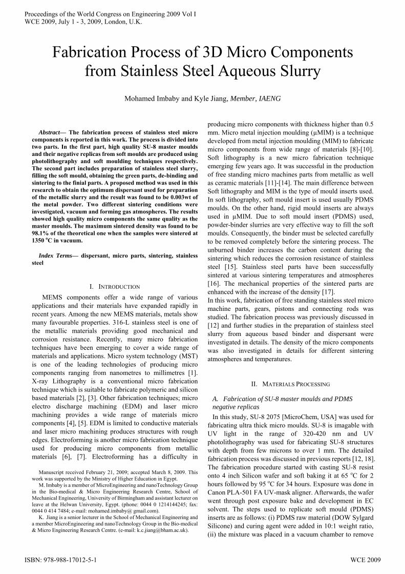
any trapped bubbles, (iii) the degassed mixture was poured on SU-8 moulds and degassed again, and (iv) the PDMS was cured in an oven at 90 οC. Fig. 1(a) and Fig. 1(b) show the SEM images of the SU-8 and PDMS micro moulds respectively.
B. Preparing stainless steel slurry and obtaining the green parts
316-L stainless steel powder (Sandvik Osprey Ltd., UK) was used in this research. The chemical compositions delivered by supplier include 65.5% Fe, 18.5% Cr, 11.6% Ni, 2.3% Mo, 1.4% Mn and other minor elements. The binder used is a mixture of aqueous emulsion Duramax B-1000 and B-1007which have been successfully used as a binder in the preparation of ceramic fabrication as reported in [13, 14]. Duramax D-3005 is an ammonium salt of acrylic homopolymer used in this research for dispersing the stainless steel powders. Metallic slurry was prepared by: (i) disperse stainless steel powder in the distilled water and dispersant, (ii) the binder B1007 and B1000 were added and the mixture were stirred by mechanical stirrer to homogenize the slurry, (ii) the slurry was degassed using vacuum to remove the bubbles formed during mixing, and (iv) the PDMS moulds were filled with the slurry and the green parts were obtained after the slurry dried. Many details about filling the mould can be found in previous research [12].
C. De-binding and sintering
Two different sintering conditions were investigated in this research as follow: (i) de-binding and sintering were done in one continuous cycle in a tube furnace with dynamic flow of forming gas atmosphere of 90% Nitrogen and 10% Hydrogen, and (ii) de-binding is done in tube furnace with nitrogen atmosphere and the sintering is done under vacuum atmosphere. In both cases, the de-binding rate is adjusted to 1.2 οC per minute until 700 οC and maintained at this temperature for 1 hour. During sintering stage, the heating rate is adjusted to be 5 οC per minute until sintering
temperature. Four different sintering temperatures were investigated in this research, 1200 οC, 1250 οC, 1300 οC, and 1350 οC. The holding time during sintering was adjusted to be 1.5 hours for all cases.
III. RESULT AND DISCUSSIONS
A. Optimization of the slurry properties
To improve the density of the green parts, a proposed method was used in this research to obtain the optimum dispersant and binder used. The process used for obtaining the optimum dispersant is presented as follow: (i) prepare stainless steel slurries containing different dispersant/powder ratio with the same solid loading and binder to study only the effect of dispersant on the green density, (ii) the PDMS moulds are filled with the slurry and the green parts obtained (iii) the green density of each dispersant/powder ratio is measured, (iv) The maximum green density is selected as the optimum ratio. Due to the complexity of micro components fabricated and difficulties in measuring the green density, PDMS mould inserts with cylindrical shape 5mm in both diameter and high were fabricated. The green density is measured directly by mass volume method. The relation between the density of the green parts and the
(a)
(b)
Fig. 1. (a) SU-8 master moulds. (b) PDMS negative replicas.
Fig. 2. Green density in relation with dispersant ratio.
Proceedings of the World Congress on Engineering 2009 Vol IWCE 2009, July 1 - 3, 2009, London, U.K.
ISBN: 978-988-17012-5-1 WCE 2009
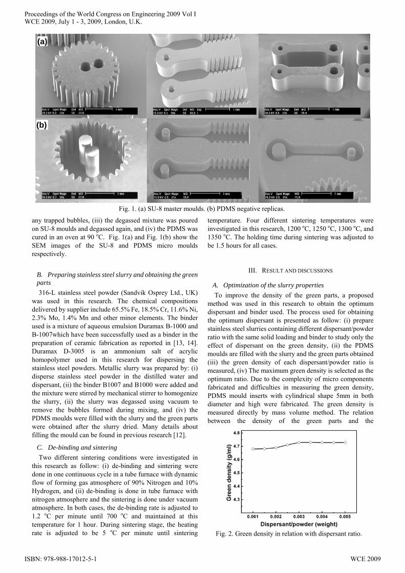
dispersant/powder weight ratio is shown in Fig. 2. It was found that increases the dispersant/powder ratio increase the green density. Moreover, the maximum green density obtained when the dispersant/powder was 0.003 by weight. After this ratio no improvements in the green density is obtained. Therefore, this ratio was selected as the optimum dispersion ratio used in this work. The binder has a great effect on the preparation of metallic slurry. Two more binder not only increases the green strength but also increase the overall de-binding time and shrinkage after sintering. Less binder produces green parts with insufficient strength which is likely to be damaged during de-moulding. In this work, it was found experimentally that using a 0.02 binder/powder ratio in weight produced more than 60% of the green samples free of damage. Therefore, the optimum amount of dispersant and binder used in this work for preparation of metallic slurry is adjusted to be 0.003 and 0.02 in weight of the stainless steel powder respectively. The solid loading is adjusted to be 87 % by weight. The green parts of the cylindrical shape as well as micro components fabricated by optimum dispersant and binder were investigated and shown in Fig. 3(a)-3(d). The high quality green micro parts are obtained which reflect the quality of the SU-8 master moulds. The powder is investigated under SEM before preparation of the green parts and after preparation as shown in Figure 3e and 3f respectively. It was found that the particles have spherical shape with different sizes. Moreover, the small particle tends to agglomerate. On the other hand, the particles in the green parts shows uniform particle distribution without agglomeration an indication of the highly effect of the dispersant to separate the agglomeration of the particles and produce homogenous slurry. As results, the separated particles tend to fill the PDMS properly than the agglomerated one and increase the density packing. That is why the green density improved with the increase of dispersant.
B. Shape retention
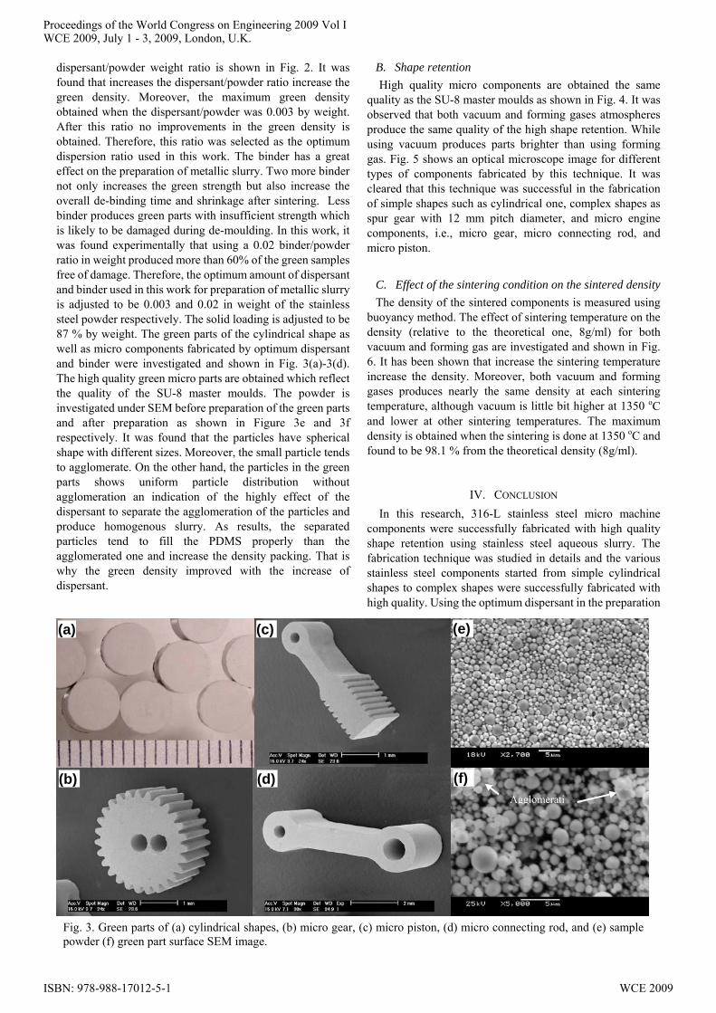
High quality micro components are obtained the same quality as the SU-8 master moulds as shown in Fig. 4. It was observed that both vacuum and forming gases atmospheres produce the same quality of the high shape retention. While using vacuum produces parts brighter than using forming gas. Fig. 5 shows an optical microscope image for different types of components fabricated by this technique. It was cleared that this technique was successful in the fabrication of simple shapes such as cylindrical one, complex shapes as spur gear with 12 mm pitch diameter, and micro engine components, i.e., micro gear, micro connecting rod, and micro piston.
C. Effect of the sintering condition on the sintered density
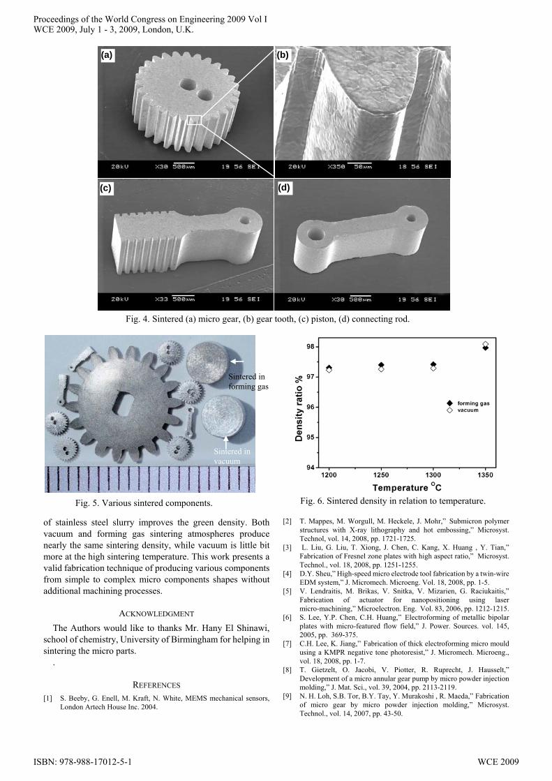
The density of the sintered components is measured using buoyancy method. The effect of sintering temperature on the density (relative to the theoretical one, 8g/ml) for both vacuum and forming gas are investigated and shown in Fig. 6. It has been shown that increase the sintering temperature increase the density. Moreover, both vacuum and forming gases produces nearly the same density at each sintering temperature, although vacuum is little bit higher at 1350 οC and lower at other sintering temperatures. The maximum density is obtained when the sintering is done at 1350 οC and found to be 98.1 % from the theoretical density (8g/ml).
IV. CONCLUSION
In this research, 316-L stainless steel micro machine components were successfully fabricated with high quality shape retention using stainless steel aqueous slurry. The fabrication technique was studied in details and the various stainless steel components started from simple cylindrical shapes to complex shapes were successfully fabricated with high quality. Using the optimum dispersant in the preparation
Fig. 3. Green parts of (a) cylindrical shapes, (b) micro gear, (c) micro piston, (d) micro connecting rod, and (e) samplepowder (f) green part surface SEM image.
Agglomerati
(c) (a)
(d) (b)
(e)
(f)
Proceedings of the World Congress on Engineering 2009 Vol IWCE 2009, July 1 - 3, 2009, London, U.K.
ISBN: 978-988-17012-5-1 WCE 2009
of stainless steel slurry improves the green density. Both vacuum and forming gas sintering atmospheres produce nearly the same sintering density, while vacuum is little bit more at the high sintering temperature. This work presents a valid fabrication technique of producing various components from simple to complex micro components shapes without additional machining processes.
ACKNOWLEDGMENT
The Authors would like to thanks Mr. Hany El Shinawi, school of chemistry, University of Birmingham for helping in sintering the micro parts.
.
REFERENCES [1] S. Beeby, G. Enell, M. Kraft, N. White, MEMS mechanical sensors,
London Artech House Inc. 2004.
[2] T. Mappes, M. Worgull, M. Heckele, J. Mohr,” Submicron polymer structures with X-ray lithography and hot embossing,” Microsyst. Technol, vol. 14, 2008, pp. 1721-1725.
[3] L. Liu, G. Liu, T. Xiong, J. Chen, C. Kang, X. Huang , Y. Tian,” Fabrication of Fresnel zone plates with high aspect ratio,” Microsyst. Technol., vol. 18, 2008, pp. 1251-1255.
[4] D.Y. Sheu,” High-speed micro electrode tool fabrication by a twin-wire EDM system,” J. Micromech. Microeng. Vol. 18, 2008, pp. 1-5.
[5] V. Lendraitis, M. Brikas, V. Snitka, V. Mizarien, G. Raciukaitis,” Fabrication of actuator for nanopositioning using laser micro-machining,” Microelectron. Eng. Vol. 83, 2006, pp. 1212-1215.
[6] S. Lee, Y.P. Chen, C.H. Huang,” Electroforming of metallic bipolar plates with micro-featured flow field,” J. Power. Sources. vol. 145, 2005, pp. 369-375.
[7] C.H. Lee, K. Jiang,” Fabrication of thick electroforming micro mould using a KMPR negative tone photoresist,” J. Micromech. Microeng., vol. 18, 2008, pp. 1-7.
[8] T. Gietzelt, O. Jacobi, V. Piotter, R. Ruprecht, J. Hausselt,” Development of a micro annular gear pump by micro powder injection molding,” J. Mat. Sci., vol. 39, 2004, pp. 2113-2119.
[9] N. H. Loh, S.B. Tor, B.Y. Tay, Y. Murakoshi , R. Maeda,” Fabrication of micro gear by micro powder injection molding,” Microsyst. Technol., vol. 14, 2007, pp. 43-50.
Fig. 4. Sintered (a) micro gear, (b) gear tooth, (c) piston, (d) connecting rod.
(a) (b)
(c) (d)
Fig. 5. Various sintered components.
Sintered in forming gas
Sintered in vacuum
Fig. 6. Sintered density in relation to temperature.
Proceedings of the World Congress on Engineering 2009 Vol IWCE 2009, July 1 - 3, 2009, London, U.K.
ISBN: 978-988-17012-5-1 WCE 2009
[10] H. Yea, X. Y. Liub, H. Honga,” Fabrication of metal matrix composites by metal,” J. Mater. Process. Technol., vol. 200, 2008, pp. 12-24.
[11] J.S. Kim, K. Jiang, I. Chang,” Pressure Free Fabrication of 3D Microcomponents Using Al Powder,” Adv. Eng. Mater., vol. 8, 2006, pp. 38-41.
[12] M. Imbaby, K. Jiang, I. Chang,” Fabrication of 316-L stainless steel micro parts by softlithography and powder metallurgy,” Mater. Lett., vol. 62, 2008, pp. 4213-4216.
[13] D. Zhang, B. Su, T. W. Button,”Microfabrication of three-dimensional, free-standing ceramic MEMS components by soft moulding,” Adv. Eng. Mater., vol. 5, 2003, pp. 924-927..
[14] Z. Zhu, X. Wei, K. Jiang,” A net-shape fabrication process of alumina micro-components using a soft lithography technique,” J. Micromech. Microeng., vol. 17, 2007, pp. 193-198.
[15] L. Castro, S. Merino, B. Levenfeld, A. Varez, J. M. Torralba,” Mechanical properties and pitting corrosion behaviour of 316L stainless steel parts obtained by a modified metal injection moulding process,” J. Mater. Process. Technol., vol. 144, 2003, pp. 397-402.
[16] C. H. Ji, N. H. Loh, K. A. Khor, S. B. Tor,” Sintering study of 316L stainless steel metal injection molding parts using Taguchi method: final density,” Mater. Sci. Eng., vol A 311, 2001, pp. 74-82.
[17] S. Li, B. Huang, D. Li, Y. Li, S. Liang, H. Zhou,” In uences of sintering atmospheres on densication process of injection moulded gas atomised 316L stainless steel,” Powder Metall., vol. 46, 2003, pp. 241-245.
[18] P. Jin, K. Jiang, N. Sun,” Microfabrication of ultra-thick SU-8 photoresist for microengines,” J. Microlith. Microfab. Microsys., vol. 3, 2004, pp. 569-574.
Proceedings of the World Congress on Engineering 2009 Vol IWCE 2009, July 1 - 3, 2009, London, U.K.
ISBN: 978-988-17012-5-1 WCE 2009