Fabco-Air Inc. Specialsfabco-air.com/pdf/CV9_01-19-07.pdf · attachment and positive manual...
193
-
Upload
nguyenmien -
Category
Documents
-
view
225 -
download
1
Transcript of Fabco-Air Inc. Specialsfabco-air.com/pdf/CV9_01-19-07.pdf · attachment and positive manual...


Fabco-Air Inc. Specials0
ii 3/25/98
Specials...Consider asking Fabco-Air for a modified or specialproduct to meet your necessary and specific re-quirements. Fabco-Air has the willingness, years ofexperience, manpower and equipment available todesign, adapt, modify and produce in any quantity,existing or new products to meet your job require-ments more effectively. Please contact your localdistributor with details of your requirements so thatwe may assist you.
The photos here show just a few examples of thethousands of specials that have been producedover the past three decades.
1/2 NPT Valve Stack■ Manifolded inlet into both valves ■ One solenoidcontrolled valve with internal orificing to pilot operatesecond valve
Pancake®
■ Rear tapped mount with extension hub
Pancake®
■ Heavy spring extend ■ Front flange mount
1/2 NPT Valve■ 3 way with heavy spring ■ Provision for operatorattachment and positive manual override for footoperation
Pancake®
■ 3 position

Fabco-Air Inc. Specials0
iii3/25/98
Pancake®
■ Double rods with hole through concentric shafts andindependent ports for stripper control
Modular Valve Bank■ Stacked with mounting brackets ■ Swivel flow controls■ Fittings ■ Wire terminals ■ Wire insulation installed
Hi-Power™■ Double rod ■ oversized rods■ Oversized hole through
Longstroke® Pivot Mount■ 2 stage Multi-Power® principle
Square 1®
■ 2 stage Multi-Power® principle
Pancake®
■ 2 stage Multi-Power® principle

1
Pancake® Cylinders
Specifications subject to change without notice or incurring obligation1.1
Page
Features & Benefits ......................................................................... 1.2
General, Standard Specifications .................................................... 1.2
Construction Details ........................................................................ 1.3, 1.4How a Pancake® is built
Action Information ........................................................................... 1.5, 1.6How a Pancake® Functions
Option Information........................................................................... 1.7 - 1.14, 1.65, 1.66Description of Options
Custom Options and Specials ......................................................... 1.15
Air Spring ........................................................................................ 1.15
AccessoriesFlow Controls, Port Mounted and Others ............................ 1.16Position Sensors .................................................................. 1.14, 1.16Mounting Bolts ..................................................................... 1.16Wrench Flat Wrench ............................................................ 1.16
Detailed SpecificationModel Number CodesHow to OrderStandard DimensionsSeal Kit Part NumbersMagnetic Piston Position SensingOption Dimensions
1/2" (5) Bore ............................................ 1.17 - 1.223/4" (7) Bore ............................................ 1.23 - 1.281-1/8" (121) Bore ............................................ 1.29 - 1.341-5/8" (221) Bore ............................................ 1.35 - 1.402" (321) Bore ............................................ 1.41 - 1.462-1/2" (521) Bore ............................................ 1.47 - 1.523" (721) Bore ............................................ 1.53 - 1.584" (1221) Bore ............................................ 1.59 - 1.64
Flow ControlsPort Mounted and Others .................................................... Section 12
Specials ....................................................................................... ii, iii
2 Year Warranty ............................................................................... Inside back cover
Section 1 IndexOriginal & “T” Series8 Bores, 1/2" – 4"
4-22-04

1
Specifications subject to change without notice or incurring obligation
Pancake® Cylinders
1.24-22-04
Features Benefits• Machined from aluminum bar-stock . . . . . . • Strength, precision & clean lines
• Heavy wall construction . . . . . . . . . . . . . . . • Bore protection
• Internally lubricated O-rings . . . . . . . . . . . . • Smooth operation & long life
• Duralon® nonmetallic rod bushing . . . . . . . . • Superior bushing & rod life
• Hard chrome plated stainless steel piston rod . . . . . . . . . . . . . . . • Long life, corrosion resistance
• Crosshatch polished bore . . . . . . . . . . . . . . • Lubrication retention for seal life
• More bores, strokes, options . . . . . . . . . . . . • Fit your application
• Clear anodized . . . . . . . . . . . . . . . . . . . . . . • Appearance & corrosion resistance
• Internal guide pins in non-rotating . . . . . . . • Protected from environment
• Prelubed with Magnalube®-G Grease . . . . . • Long life, smooth operation
• "T" Series . . . . . . . . . . . . . . . . . . . . . . . . . . • Includes PTFE piston bearing
• 2 Year warranty . . . . . . . . . . . . . . . . . . . . . . • Extended buyer protection
General, Standard SpecificationsMedia . . . . . . . . . . . . . . . . . . . . . . Air . . . . . . . Optional - HydraulicMaximum operating pressure . . . . 250 psi . . . Optional - 500 psiMinimum operating pressure . . . . . See page 1.4, Item 4Ambient & media temperature . . . –25° to + 250°FPrelubrication . . . . . . . . . . . . . . . . Magnalube®-G GreaseAir line lubrication . . . . . . . . . . . . . RecommendedStroke tolerance . . . . . . . . . . . . . . ± 1/64"
Original & “T” Series8 Bores, 1/2" – 4"
Features & Benefits
Original Series
Original Series
Original Series, Nonrotating
“T” Series
Laboratory tests confirm thatinternally lubricated Buna-NO-ring seals have extendedPancake® cylinder life 2 to 3times beyond that of cylindersusing standard Buna-N seals.
This, the original Pancake® Cylinder, was designed in 1958 tosatisfy the need for short stroke cylinders that would fit in very tightspaces. Today, with almost four decades of experience in thousandsof cylinder applications around the world, The Pancake® Line offersyou far more than any of its imitators – more features and options –better quality, strength and appearance – and far longer product life!
We are so confident in our design and manufacturing skills thatwe back every Pancake® Cylinder with our 2-year Warranty!

1
Pancake® Cylinders
Specifications subject to change without notice or incurring obligation4-9-04
Construction Details
6 5
8
19
419 10
7 4
Single Rod – Double ActingAction - X
1/2" & 3/4" Bores
6 4
10
12
19
41019
19
413
Double Rod – Double ActingAction - XDR
1/2" & 3/4" Bores
6 5
8
1
9
419
4
10
7 14
Single Rod – Double ActingAction - X
1/2" & 3/4" Bores
2
1
4
4
103
18
9
15
8
716
56
2
1
4
14
103
18
9
15
716 5
4
8
6
1.3
2
1
4
4
103
9
78
56
2
1
4
14
103
9
78 5
46
2
1
4103
9
12
6
4
4
10
3
13
11
Double Rod – Double ActingAction - XDR
Single Rod – Double Acting –NonrotatingAction - XK
Single Rod – Double ActingAction - X
Single Rod – Double Acting –NonrotatingAction - XK
Single Rod – Double ActingAction - X
“T” Series (PTFE Piston Bearing)
Original & “T” Series8 Bores, 1/2" – 4"
Original Series
Single Rod - Double ActingAction -X shown

1
Specifications subject to change without notice or incurring obligation
Pancake® Cylinders
1. The heavy wall prohibits any damage to the bore from externalforces.
2. The one piece cylinder body and bushing support end is ma-chined from solid aluminum bar-stock. This provides unequalledstrength, rigidity, and piston rod support. Machining all surfaces pro-vides perpendicularity and concentricity for locating, mounting, andmaking attachments to the rod. It also presents a clean, smooth,"no-dirt-catching" appearance on your machine.
3. Unique construction provides unequalled piston rod support andprohibits “Blowout”! The one piece Duralon® rod bushing is insertedfrom the inside and then staked in place. Duralon® is a Teflon® linedfiberglass structure with a load carrying capacity of 60,000 psi. Com-pare capacity with Nylon® at 1,000 psi, porous bronze at 4,500 psi,and porous iron at 8,000 psi. Duralon also provides: CONSISTENCY,reliable and predictable performance from bushing to bushing; COR-ROSION RESISTANCE, nonmetallic materials resist galvanic, chemi-cal and fretting corrosion; SELF LUBRICATION, Teflon® lining pro-vides low friction and minimizes stickslip, even under no-lube condi-tions; SEIZURE RESISTANCE, fiberglass backing material will notseize or gall on shaft under extreme wear. Generally the bearing lengthis increased as the stroke increases, providing even more piston rodsupport.
4. Internally lubricated Buna-N O'Rings (-25° to + 250°F) providelow profile, low friction, and long life sealing of piston and rod. Allstatic seals are Buna-N.
These dynamic O'Rings are compounded to provide extra long wearand lower breakaway (starting) and running friction and smootheroperation. In tests, cylinders with internally lubricated O'Rings haveextended cycle life two to three times beyond cylinders with standardBuna-N seals. The chart below shows maximum breakaway or start-ing pressure to extend the rod of single rod, double acting (Action -X)cylinders with internally lubricated O'Rings under no-load conditionsafter 3 days delay at zero pressure. With other actions and/or combi-nations of options, breakaway pressures may vary.
Bore Number 5 7 121 221 321 521 721 1221Bore, Inches 1/2 3/4 1-1/8 1-5/8 2 2-1/2 3 4Breakaway psi 12.0 6.5 4.5 4.5 4.0 3.0 3.0 2.5
These low operating pressures allow for the use of vacuum as anOperating Media in many applications. 1.0 psi is the equivalent of2.04" Hg of vacuum. To determine the force output of a cylinder withvacuum, multiply: Force Area of cylinder x inch Hg vacuum x 0.49 =Force, lb.
5. The thinnest possible piston and rear cover design keeps theoverall height as short as possible. Please note that any cylinderoffering less height than that of a Pancake® with the same stroke,sacrifices rod bushing length and/or overall strength.
6. The aluminum cover is held in place with multiple plated screwsfor strength, rigidity, ease of modification for specific application re-quirements, and ease of access for maintenance should it be required.
7. The aluminum piston is attached to the piston rod with a socketflat head cap screw which is torqued for proper preload on the screwand clamping of the piston. Loctite® on the threads and faces assuressealing and locks the assembly against pounding and vibration.
8. The piston in all bores has a counterbore for piston rod locationand control of concentricity between piston rod and piston O.D.
4-22-04 1.4
Original & “T” Series8 Bores, 1/2" – 4"
9. Polishing the cylinder bore and piston rod produces a fine cross-hatched finish. This crosshatching provides minute oil ring type groovesfor retaining lubrication. This finish, unlike an ultra smooth finish, pro-vides a place for lubrication to lie and support the seal as it movesalong the surface. The surface finish and lubrication provide lowerfriction and longer seal life.
10. The piston rod is centerless ground, polished, and hard chromeplated (68-72 Rc) stainless steel. Surface finish is 12 RMS or betterand carries lubrication like our cylinder bore (see 9). These featurescombined with the low friction and high load capacity of the Duralon®
bushing provide exceptional cylinder life. Female, fine pitch rod threadand wrench flats are standard.
11. A pilot diameter on the cover is concentric with the rod bushingand locates in the cylinder bore to maintain the concentricity, preci-sion, and rigidity of the Pancake® design.
12. Counterbores on both sides of the piston maintain concentric-ity of piston rods to each other as well as to the piston O'Ring. Thisalso provides complete axial and radial rigidity of the piston so that itcannot float or be pounded loose.
13. The piston rods are connected by a high strength stud, sand-wiching the piston between the rod end faces. The assembly is torquedfor proper preload of the stud and clamping of the piston head. Loctite®
on the threads and faces assures sealing and locks the assemblyagainst pounding and vibration. This procedure provides a positiveand rigid assembly that will not allow the piston to float or be poundedloose.
14. The "T" Series has a thicker piston which incorporates a bear-ing strip in addition to the O-ring seal. This bearing strip is a closetolerance, rectangular cross section strip of a tough, stable, wear re-sistant PTFE compound. If the piston rod assembly is forced off cen-ter by misalignment or other forces, this bearing, along with the longand rigid Duralon® rod bushing, supports the load and helps to main-tain the long life of the cylinder bore and O-ring seal. Note: the bear-ing is not included, or required in double rod models because thelong rod bushings at each end of the cylinder provide superb support.
15. Two guide pins of precision ground tool steel pass through thepiston head. These guide pins prevent rotation of the rod with a toler-ance of ±1°. Note that the guide pins are located internally. This pro-vides protection from the environment and from physical damage.Lubrication is provided with other internal parts. NO additional spaceis required and the rod end is left free for attachments and tooling asrequired by the application. An information label, similar to this one, isapplied to each cylinder to warn against damage.
WARNINGTHIS CYLINDER HAS A NONROTATING ROD.TO PREVENT INTERNAL DAMAGE HOLD ROD BY WRENCHFLATS WHEN INSTALLING OR REMOVING ATTACHMENTS
16. The guide pins pass through Polyurethane O'Ring seals andSAE660 bearing bronze bushings incorporated in the piston head.This combination provides no leak, precision guiding and long life.
18. A disk of rubber is included at the end of the guide pins to takeup play and firmly seat the pins in the precision machined guide pinholes.
19. Integral rod bearing and endcap is hard anodized aluminum.The piston rod seal O-ring is located as close to the outer end asfeasible so that as much of the bearing as possible gets system lubri-cation as well as protecting most of the bearing length from the envi-ronment. A precision machined pilot diameter locates the cylinder boreto assure concentricity and proper rod alignment.
Nearly 4 decades of experience paying close attentionto design detail, production and assembly techniqueshave resulted in the ultimate Fabco-Air Pancake®, shortstroke cylinders. Pancakes® fit into very tight spacesand virtually ANY short stroke cylinder application.Think how well they will fit with your application!
Construction Details

1
Pancake® Cylinders
Specifications subject to change without notice or incurring obligation1.5
C-221-X TC-221-X
C-221-XK TC-221-XK
C-221-O TC-221-O
C-221-OP TC-221-OP
“T” SeriesPTFE Piston BearingOriginal Series Action Letter
Action Description
Action -X
Single RodDouble Acting
One Piston RodPower Extend - Power Retract
NFPASymbol
Action -XK
150 psi maximumSingle Rod
Double ActingNonrotating
One Piston RodPower Extend - Power Retract
Piston guide pins for nonrotating
Action -O
Single RodSingle Acting - Spring Retracted
One Piston RodPower Extend - Spring Retract
Action -OP
Single RodSingle Acting - Spring Extended
One Piston RodSpring Extend - Power Retract
4-22-04
Action InformationOriginal & “T” Series8 Bores, 1/2" – 4"

1
Specifications subject to change without notice or incurring obligation
Pancake® Cylinders
1.6
C-221-XDR
C-221-XDRK
C-221-ODR
4-8-04
“T” SeriesPTFE Piston BearingOriginal Series Action Letter
Action DescriptionNFPA
Symbol
Action -XDR
Double RodDouble Acting
Two Piston Rods - One each endPower Extend - Power Retract
Action -XDRK
150 psi maximumDouble Rod
Double ActingNonrotating
Two Piston Rods - One each endPower Extend - Power Retract
Piston guide pins for nonrotating
Action -ODR
Double RodSingle Acting - Spring Retracted
Two Piston Rods - One each endPower Extend - Spring Retract
The “T” Series is not requiredin the double rod version.
Two rod bushings providesuperb rod support
The “T” Series is not requiredin the double rod version.
Two rod bushings providesuperb rod support
The “T” Series is not requiredin the double rod version.
Two rod bushings providesuperb rod support
The “Action Letter” portion of the Pancake® Model Number specifies how manypiston rods the cylinder has (Single Rod or Double Rod), how the piston rod isextended and retracted (Double Acting or Single Acting), and if the piston rod isrestricted from rotating by internal guide pins (Nonrotating).
Action InformationOriginal & “T” Series8 Bores, 1/2" – 4"

1
Pancake® Cylinders
Specifications subject to change without notice or incurring obligation1.7
Option InformationOriginal & “T” Series8 Bores, 1/2" – 4"
4-23-04
METRIC Cylinder and Rod Thread. MFemale Rod Thread is standard.
Optional Male Rod Threadadd suffix -MR
PREFIX OPTIONS
MODEL NUMBER PREFIX
PREFIX OPTIONS
Mounting holes and rod thread are configured to common METRICsizes. Ports in 1/2" (5) and 3/4" (7) bores are M5. Ports in 1-1/8" (121)bore and larger are G1/8 with 14mm spotface for 1/8 BSP-Parallelfittings and gaskets.
Available on all series, bore, stroke and action combinations.
See Option Specifications pages of desired bore and action forcomplete dimensional details.

1
Specifications subject to change without notice or incurring obligation
Pancake® Cylinders
1.8
Option InformationOriginal & “T” Series8 Bores, 1/2" – 4"
4-23-04
MALE ROD THREADSingle Rod -MRDouble Rod, Rod End Only -MRDouble Rod, Cap End Only -MR1Double Rod, Both Ends -MR2
SUFFIX OPTIONSMODEL NUMBER SUFFIX
A high strength stud is threaded into the standard female rod end andretained with Loctite®. This method eliminates the small diameter threadrelief area normally required when machining male threads. Thisprovides a much stronger rod end which can be repaired, rather thanreplacing the complete rod, should the thread be damaged.
Available on all series, bore, stroke and action combinations.
See Option Specifications pages of desired bore and action forcomplete dimensional details.
SUFFIX OPTIONS
TEFLON® O'RING SEALS(+400° to +500° F) -T
VITON® O'RING SEALS(-15° to +400° F) -V
QUAD SEALS(-30° to +250° F) -Q
NONROTATING Single Acting -NR
For Double Acting, NonrotatingSEE Action -XK, -XDRKon pages 1.5 and 1.6
A Hex Rod of stainless steel in a broached, hard anodizedaluminum endcap replaces the round rod in Single Acting, SpringRetracted (Actions -O, -ODR) cylinders.
Available in all series, bores 1/2" (5), 3/4" (7), all strokes, actions -O,-ODR.
See Option Specifications pages of desired bore and action forcomplete dimensional details.
A QUAD seal replaces the standard O'Ring on the piston only.Standard seal material is Buna-N (-30° to +250°F). For other materialsconsult engineering.
Available on all series, bore, stroke and action combinations.
See Standard Specifications pages of desired bore and actionfor complete dimensional details. There are no dimensional changes fromstandard.
For elevated temperatures (–15° to + 400°F) or compatibility with ex-otic medias. Consult engineering for compatibility information.
Available on all series, bore, stroke and action combinations.
See Standard Specifications pages of desired bore and actionfor complete dimensional details. There are no dimensional changes fromstandard.
For elevated temperatures (+400° to +500° F) or compatibility withexotic medias. Consult engineering for compatibility information.
NOTE: Teflon seals are NOT for low friction. This seal materialassumes the shape of the rectangular groove, exhibits no “memory”andwill not return to round O'Ring cross section. Therefore the piston androd seals may exhibit some leakage. This is even more pronounced inapplications that require thermal cycling over wide temperature ranges.They are not, therefore, recommended for such applications.
Available on all series, bores 1-1/8" (121) and larger, all strokes andactions -X, -XDR.
See Standard Specifications pages of desired bore and action forcomplete dimensional details. There are no dimensional changes fromstandard.

1
Pancake® Cylinders
Specifications subject to change without notice or incurring obligation1.9
Construction DetailsOriginal & "T" Series8 Bores, 1/2" – 4"
HYDRAULIC, Low Pressure Serviceto 500 psi NONSHOCK.Temperature to +300° F max.
Consult factory for media compatabilityand operating temperatures over 300°F.
With Standard ThicknessCover -H
With Thick Cover -HHC
SUFFIX OPTIONS
For Air-Oil or Hydraulic systems to 500 psi NONSHOCK.
1. A specially formulated U-Cup seal replaces the O-ring piston rod seal.This eliminates leakage past the rod seal and around the bushing.
2. Option -HHC, on single rod bores 1-5/8" (221) & larger, includes a thickerrear cover to assure that there is no warpage or failure when the mountingsurface is the Rod End Face. See chart below.
3. 1/4 NPT Ports are available on bores 1-5/8" (221) & larger. See Option-P14 below.
4. Single Acting (Spring Return) Cylinders are designed for the spring toreturn the piston & rod assembly. Because of the low return forces available &the somewhat restricted flow, the piston returns slowly when used with oil atany pressure. Double Acting Cylinders are therefore recommended forHydraulic service.
–H is available on all series, bores 1-1/8" (121) and larger, actions -X & -O,-OP, -XDR & -ODR, all strokes. Available also for Actions -XK & -XDRK onbores 2-1/2" (521) and larger. Consult factory for available strokes on bores1-1/8 (121) to 2" (321) and actions -XK & -XDRK.
-HHC is available on all series. Bores 1-5/8" (221) and larger, all strokes,Actions -X & -O.
SEE Option Specifications pages of desired Bore & Action for completedimensional details.
U-CupRod Seal
DURALON® Rod Bearing
SUFFIX OPTIONSMODEL NUMBER SUFFIX
OPTION –H –H –H –H –H –HHCACTION –X, –O –OP –XDR, –ODR –XK –XDRK –X, –O
250 500 500 150 150 500
500 500 500 150 150 500
–F 250 500 500 150 150 500
–PM 500 500 NA 150 NA NA
–SM 500 500 NA 150 NA NA
–EPM 500 500 NA 150 NA NA
–ESM 500 500 NA 150 NA NA
–AS 500 NA NA 150 NA NA
–RS 500 500 NA 150 NA NA
Mounting surfaceis at rod end
Mounting surfaceis at cap end
Pressure Ratings (psi) for Various Mountings
Other Options in Combination with –H or –HHC
-HC includes the thick rear cover. It is for AIR service, to 250 psi,when thethick rear cover is desired.
Available on all series, Bores 1 5/8" (221) and larger, all strokes, Actions; -X, -O.
See Option Specifications pages of desired Bore and Action for completedimensional details.
AIR SERVICEWith Thick Cover -HC
1/4 NPT PORTS -P14
4-23-04
Port size 1/4 NPT. On bores 1-5/8" (221) and 2" (321) the orifice betweenthe port and the bore is also increased. All ports are in the standard loca-tions.
Use when reduced pressure drop or higher cycle speeds are desired.They are particularly advantageous in Air-Oil Hydraulic applications.
Available on all series, bores 1-5/8" (221) & larger, all strokes, all actions.
See Standard Specifications pages of desired bore & action for completedimensional details. There are no dimensional changes from standard otherthan port size.

1
Specifications subject to change without notice or incurring obligation
Pancake® Cylinders
1.10
SUFFIX OPTIONS150 psi maximum operating pressure
A hole is drilled through the piston rods & the double rod stud (seeconstruction details on page 1.3). This hole is used for the passage ofVacuum, Air, Gas, Oil, Liquid or any media that is compatible with thestainless steel piston rod and the steel stud. Maximum pressure, 150 psi.Hole sizes available for each bore size are shown in the chart to the left. If alarger hole is needed (for higher flows or mechanical members) or allstainless steel construction is needed (for compatibility or higher pressure)see "One Piece Piston & Rod Construction" under Custom Options on page1.15.
Insert the SUFFIX Number into the Model Number immediately after thedesired Action. For example: -XDR13
Available on Original Series, all Bores, all Strokes, Action; -XDR, -XDRK,-ODR.
See Standard Specifications pages of desired Bore & Action for completedimensional details. There are no dimensional changes from standard.
SUFFIX OPTIONS
Option InformationOriginal & "T" Series8 Bores, 1/2" – 4"
HOLE THRU Double Rod Shaft
Standard Standard PlusModel No. Model No.
Hole Size Suffix Hole Size SuffixBore thru stud (Std) thru stud (Std Plus)
1/2", 3/4" 1/16 -06 – –1-1/8" 1/8 -13 5/32 -161-5/8" 1/8 -13 1/4 -25
2" 5/32 -16 5/16 -312-1/2" 5/32 -16 1/4 -25
3" 5/32 -16 1/4 -254" 1/4 -25 – –
For those "in-between" strokes, a STROKE COLLAR is incorporated onthe piston rod. The collar fits tightly on the piston rod so that it cannot floatas the piston is stroked. Tolerance on the stroke is ± 1/64". For tightertolerances on the stroke or final rod position, consult Engineering.
Available on all Series, all Bores, all Strokes, Actions; -X, -XDR, -OP.Also all series, Bores 3/4" (7) and larger, all Strokes, Actions; -XK,-XDRK. Also all Series, Bores 1/2" (5) & 3/4" (7), Actions; -O, -ODR.
SEE Standard Specificationspages of desired Bore & Action forcomplete dimensional details.
Cap End Rod Stick-out of DoubleRod Units increases by amount strokeis shortened.
Stroke Collar
4-23-04
Pro-Coat™, Electroless Nickel Plating, is a hard, smooth, corrosion andwear resistant coating. It will often suffice for applications where stainless steelis specified. Its lasting luster provides high visual appeal.
The coating is a high nickel, low phosphorous alloy deposited by chemicalreduction without electric current that is “mil-for-mil” more corrosion resistantthan electroplated nickel. The surface is virtually pore free. The thickness of thenickel deposit is consistent over the entire surface. Blind holes, threads, smalldiameter holes and internal surfaces all receive the same amount of plating. Ithas natural lubricity and a high resistance to abrasion. As shipped hardness ofthe coating is approximately 49 Rockwell C. Heat treating can increase hard-ness to approximately 60 Rockwell C. For specific applications, consult engi-neering.
Besides cylinder parts, Pro-Coat™ may be applied to valve bodies, sole-noid housings, fittings and most any item that appears in this catalog.
Pro-Coat™ is available on all series, bore, stroke and action combinations.
See Standard Specifications pages of desired bore and action for completedimensional details. There are no dimensional changes from standard.
FINISH: Clear anodize is standard.
Plating: Pro-Coat™Electroless Nickel -N
RodRod
Piston Stud
STROKE COLLAR
on Piston Rod in 1/8" increments.
1) Start with the nextlongest stroke.
2) Select the amountthe stroke is to beshortened.
3) Specify thecorrespondingSUFFIX designation.
1/8" -C11/4" -C23/8" -C31/2" -C45/8" -C53/4" -C67/8" -C7

1
Pancake® Cylinders
Specifications subject to change without notice or incurring obligation
Option InformationOriginal & "T" Series8 Bores, 1/2" – 4"
ADJUSTABLE EXTEND STROKE
For strokes through 4". -ASFull stroke adjustment is standard.
SUFFIX OPTIONSMODEL NUMBER SUFFIX
SUFFIX OPTIONS
Dial-A-Stroke® provides a rugged and precision adjustment of theextend stroke of the cylinder. The stop tube, adjustment nut with skirt &minimum clearances combine to eliminate pinch points, thus providingoperator safety. Note! Use caution when mounting to avoid creating pinchpoints with other parts of your machine design.
The stop tube is blue anodized aluminum, the adjustment nut isblackened steel with a black anodized aluminum skirt, and the stop flangeis red anodized aluminum; all for corrosion resistance and appearance.The adjustment nut, steel for long life, includes a lock screw with a plas-tic plug so that the adjustment nut can be locked in place without dam-aging the threads. The stop flange is mounted on the end of the adjust-ment rod so that the nut cannot come off. The fine pitch threads onthe adjustment rod and nut provide precision adjustment. Bores 1-1/8"(121) and 1-5/8" (221) have a 1/2-20 thread giving .050" adjustmentper revolution & Bores 2" (321) & larger have a 3/4-16 thread giving.063" adjustment per revolution.
The -AS designation provides full stroke adjustment.
Available on Original Series, Bores 1 1/8" (121) & larger, all Strokes,Actions; -X, -XK, -O.
SEE Option Specifications pages of desired Bore and Action forcomplete dimensional details.
Contact Surfaces Totally Enclosed
Adjustment Rod
Adjustment Nut with Fine Pitch Thread
Stop Flange
Plastic PlugLock Screw
Adjustment Nut SkirtStop Tube
1/2" Min. Clearance when Fully Stroked
1.114-23-04
C-221-X-AS
NOTE! Use caution when mountingto avoid creating pinch poiunts.
Adjustment settings are simplifiedby convenient scale markingsapplied to nut skirt and stop tube.
ADJUSTABLE RETRACT STROKE
Any stroke with up to andincluding 1" adjustment. . . . . . . -RSAny stroke with over1" adjustment,specify adjustmentlength after the -RSExample: 2" adjustment. . . . . . -RS2
D-221-X-RS
An adjusting screw with a thread sealing locknut mounted in a thickrear cover provides a simple yet rugged and precision adjustment of thecylinder stroke in the retract direction. The fine thread of the adjustingscrew provides precision adjustment. Bores 1/2" (5), 3/4" (7), have a5/16-24 thread giving .042" adjustment per revolution. Bore 1-1/8" (121)has a 3/8-24 thread giving .042" adjustment per revolution. Bores 1-5/8"(221) and larger have a 1/2-20 thread giving .050" adjustment perrevolution.
The –RS designation provides full stroke adjustment of any cylinderwith 1" stroke or less, and 1" of stroke adjustment on all longer strokes.When longer adjustments are required, on longer cylinders, add thedesired adjustment to the -RS designation (1/2" increments please).Example:-RS2 will provide 2" of adjustment on any cylinder with 2" ormore of stroke.
Available on all series, all bores, all strokes, actions -X, -XK, -O, -OP.
See Option Specifications pages of desired bore and action for com-plete dimensional details.

1
Specifications subject to change without notice or incurring obligation
Pancake® Cylinders
1.124-23-04
Option InformationOriginal & "T" Series8 Bores, 1/2" – 4"
SOUND LIMITERS
Rod End Only -LFCap End Only -LRBoth Rod and Cap Ends -LFR
Temperature Range: –25° to +220° F
SUFFIX OPTIONSMODEL NUMBER SUFFIX
RUBBER BUMPERS
Rod End Only -BFCap End Only -BRBoth Rod and Cap Ends -BFR
Temperature Range: –25° to +220° F
Rubber
Standard rubber mass providedwill compress and give full strokeat 60-80 psi.Mass can be adjusted to meetyour specific pressure and/ordynamic load requirements
SoundLimitingO'RingCushion
A rubber doughnut is bonded to the cylinder head to act as the pistonstop and absorb the impact of the piston. This reduces noise and absorbsenergy, thus reducing destruction of the cylinder and tooling due topounding. The amount of rubber that extends beyond the normal pistonstop is designed to compress and allow full stroke of the cylinder at 60 to80 psi. If your application uses lower pressure or has high energy, consultengineering with application details so that rubber mass can be adjustedto meet your specific requirements.
On applications such as punching, shearing, etc., where high forcesare built up and then very quickly released, the proper method of “CATCH-ING” this load is to adjust the position of the cylinder and tooling so at thepoint of breakthrough the piston is very close to or touching the bumper.This reduces the dynamic load that the piston and bumper are required toabsorb. It is highly recommended that shock absorbers be consideredand built into the tooling to assist in absorbing the force and dynamicloads generated in such applications.
Because of the temperature limitations of the adhesives involved (-25°to + 220°F) Rubber Bumpers are available in cylinders with standardinternally lubricated Buna-N seals only.
Use to reduce noise and absorb impact.
Note! The springs in single acting models are designed to return onlythe piston and rod assembly and will not significantly compress the rub-ber bumpers.
Available on all series, all bores, all strokes, actions -X, -XK, -O (Capend only, -BR), -OP (Rod end only, -BF), -XDR, XDRK, -ODR (Cap endonly -BR).
See Standard Specifications pages of desired bore and action for com-plete dimensional details. There are no dimensional changes from stan-dard.
For applications where you need a small amount of cushion at the endof the cylinder stroke to take out the metallic “slap” of piston head onpiston stop. This is accomplished by placing an O'Ring on the piston,and/or in the rear cover so that initial contact is with the elastomerand not metal-to-metal.
The Fabco-Air design assures sufficient compression of the seals toallow full stroke.
Because of the temperature limitations of the adhesives involved, soundlimiters are available in cylinders with internally lubricated Buna-N O'Ringsonly.
Available on all series, all bores, all strokes, actions -X, -O (Cap endonly, -LR), -OP, -XDR, XDRK, -ODR (Cap end only -LR).
See Standard Specifications pages of desired bore and action forcomplete dimensional details. There are no dimensional changes fromstandard.
SUFFIX OPTIONS

1
Pancake® Cylinders
Specifications subject to change without notice or incurring obligation1.13
Option InformationOriginal & "T" Series8 Bores, 1/2" – 4"
SUFFIX OPTIONS
CLEVIS (Pivot) MOUNTPorts in Line with Slot -PMPorts 90° to Slot -SM
SUFFIX OPTIONSMODEL NUMBER SUFFIX
C-221-X-PM with RC-38
C-221-X-EPM
C-221-X-F
EYE (Pivot) MOUNTPorts in Line with Tang -EPMPorts 90° to Tang -ESM
THREADED NOSE MOUNT -F THREADED NOSE with pilot diameter provides convenient, rigid andprecision mounting. A hex mounting nut is included as standard and isalso available separately. On bores 1-1/8" (121) and 1-5/8 (221) a urethanerod wiper is included, as standard, to exclude dirt from the rod bushingand seal.
Available on all series, bores:1/2" (5), 3/4" (7), 1-1/8" (121), 1-5/8" (221),all strokes, all actions.
See Option Specifications pages of desired bore and action forcomplete dimensional details of cylinder and mounting nuts.
EYE MOUNT provides a pivot point attachment to allow pivotal motionof the cylinder as the piston rod extends or retracts. The pivot is bushedwith an oil filled powdered metal bushing. On bore 1-5/8" (221) the EyeMount can be rotated 90° to provide either -EPM or -ESM option. To fur-ther assist in the mounting, rod clevises and clevis brackets are available.
In many applications requiring pivotal mounting, the cylinder is mountedwith its centerline horizontal. Due to the weight of the cylinder and itsattachments, this can result in some off center loading, and possibly bind-ing of the piston and rod, causing accelerated wear. For such applicationsthe “T” Series cylinders are recommended.
Available on all series, bores:1/2" (5), 3/4" (7), 1-1/8" (121), 1-5/8" (221)and 2" (321), all strokes, actions: -X, -XK, -O, -OP.
See Option Specifications pages of desired bore and action forcomplete dimensional details of cylinders, rod clevises and eye brackets.
CLEVIS MOUNT provides a pivot point attachment to allow pivotalmotion of the cylinder as the piston rod extends or retracts. The pivot isbushed with an oil filled powdered metal bushing. The pivot pin (416 stain-less steel) and clips are included as standard. On bores 1-5/8" (221),2-1/2" (521), 3" (721) and 4" (1221), the Clevis Mount can be rotated 90°to provide either -PM or -SM option. To further assist in the mounting,rod clevises and eye brackets are available accessories.
In many applications requiring pivotal mounting, the cylinder is mountedwith its centerline horizontal. Due to the weight of the cylinder and itsattachments, this can result in some off center loading, and possibly bind-ing of the piston and rod, causing accelerated wear. For such applicationsthe “T” Series cylinders are recommended.
Available on all series, all bores, all strokes, actions: -X, -XK, -O, -OP.
See Options Specifications pages of desired bore and action forcomplete dimensional details of cylinders, rod clevises and eye brackets.
4-23-04
1
Specifications subject to change without notice or incurring obligation
Pancake® Cylinders
1.144-23-04
Option InformationOriginal & "T" Series8 Bores, 1/2" – 4"
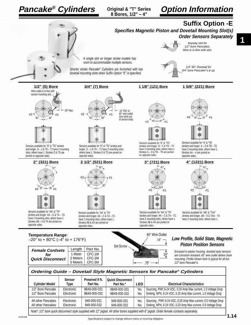
1/4" 60° Dovetail for3/4" bore Pancake®s & up.
Keyway slot for1/2" bore Pancakes.
Wire is in-line with slot.
Encased in plastic housing, dovetail style sensorsare corrosion resistant. 45° wire outlet allows closemounting. Profile shown here is typical for all but1/2" bore Pancake®s.
Shorter stroke Pancake® Cylinders are furnished with twodovetail mounting slots when Suffix Option "E" is specified.
A single slot on longer stroke models hasroom to accommodate multiple sensors.
65° 65°
Sensors available for “D” & “TD” strokes and longer. D – J & TD – TJ have 2 mounting slots; others have 1. Strokes D & TD are ported on opposite sides.
#1#2.14" Ref. to 45° wire outlet;Zero stick-out of sensor body 40° 40° #1#2
Sensors available for “D” & “TD” strokes and longer. D – F & TD – TF have 2 mounting slots; others have 1. Strokes A – D & TB – TD are ported on opposite sides.
45°
30°30°#1#2
Sensors available for “AB” & “TAA” strokes and longer. AB – A & TAA – TA have 2 mounting slots; others have 1.
45°45° #1#2
Sensors available for “A” & “TB” strokes and longer. A – D & TB – TD have 2 mounting slots; others have 1. Strokes AA – A are ported on opposite sides.
72°
35°35° #1#2
Sensors available for “AA” & “TA” strokes and longer. AA – D & TA – TD have 2 mounting slots; others have 1. Strokes AB – A & TA are ported on opposite sides.
45°
90°90°
#1#2
Sensors available for “AA” & “TA” strokes and longer. AA – C & TA – TC have 2 mounting slots; others have 1. Strokes AB & AA are ported on opposite sides.
45°
30°30°#1#2
Sensors available for “AA” & “TA” strokes and longer. AA – C & TA – TC have 2 mounting slots; others have 1. Strokes AB & AA are ported on opposite sides.
1/2" (5) Bore 3/4" (7) Bore 1 1/8" (121) Bore 1 5/8" (221) Bore
4" (1221) Bore3" (721) Bore2 1/2" (521) Bore2" (321) Bore
Suffix Option -ESpecifies Magnetic Piston and Dovetail Mounting Slot(s)
Order Sensors Separately
Low Profile, Solid State, MagneticPiston Position Sensors
Length1 Meter2 Meters5 Meters
Part No.CFC-1MCFC-2MCFC-5M
Female Cordsetsfor
Quick Disconnect
Note*: 1/2" bore quick disconnect style supplied with 12" pigtail. All other bores supplied with 6" pigtail. Order female cordsets separately.
Electrical CharacteristicsSourcing, PNP, 6-24 VDC, 0.20 Amp Max current, 1.0 Voltage DropSinking, NPN, 6-24 VDC, 0.20 Amp Max current, 1.0 Voltage Drop
Sourcing , PNP, 6-24 VDC, 0.20 Amp Max current, 0.5 Voltage DropSinking, NPN, 6-24 VDC, 0.20 Amp Max current, 0.5 Voltage Drop
Quick DisconnectPart No.*
9B49-000-3319B49-000-332
949-000-331949-000-332
Prewired 9 ft.Part No.
9B49-000-0319B49-000-032
949-000-031949-000-032
SensorType
ElectronicElectronic
ElectronicElectronic
LEDYesYes
YesYes
Cylinder Model1/2" Bore Pancake1/2" Bore Pancake
All other PancakesAll other Pancakes
Ordering Guide – Dovetail Style Magnetic Sensors for Pancake® Cylinders
Temperature Range:–20° to + 80°C (–4° to + 176°F)
#1#2
Sensors available for “D” & “TD” strokes and longer. D – J & TD – TJ have 2 mounting slots; others have 1. Strokes D & TD are ported on opposite sides.
60° 60°
.09" Max
Wire outlet is in-line withsensor mounting slot

1
Pancake® Cylinders
Specifications subject to change without notice or incurring obligation1.15
Custom Options & Specials
Specials
Let us help you!Our engineering and special products depart-
ments are willing and able to assist you with yourdesign. FABCO-AIR will produce cylinders andvalves to meet your specific application require-ments. In quantities of one and up. We have beendoing it for almost 40 years. Many of our specialshave become custom options; many have becomestandard catalog options.
Custom Options are modifications that weproduce on a routine basis, but they have too manycombinations of features for practical listing in thiscatalog. Following are just a few of the more com-mon of these custom options:
• Custom rod extensions• Custom rod end configurations• Pilot diameters on mounting faces• 1 Piece double rod, piston & rod assembly
with or without a hole through• Rod wipers, urethane or metallic• Thick covers with ports• Covers with manifolding• Other materials• Other lubricants• Strokes other than listed
with special length bodies and rods• Mounting styles & dimensions to specifications• Back-to-Back cylinders for 3 or 4 positions• Multiple position cylinders–
Tandem type for 3 or more positions
4-9-04
Constant Low Pressure Reg.
Air Springs
• An air spring allows the use of any standard double acting cylinder as a singleacting spring return (push or pull) type. To accomplish this simply connect a constantregulated pressure (must be a relieving regulator) to the proper port of the double actingcylinder.
• This system gives you a variable spring load (by adjusting the pressure) that isconsistent over the full stroke and life of the cylinder and will not break as helicalcompression springs often do.
• For space and cost savings, one regulator can serve several cylinders on the samemachine.
• Small regulator supplies constant pressure & controls spring force.• Connection to Rod End Port results in a spring retracted type cylinder• Connection to Cap End Port results in a spring extended type cylinder

1
Specifications subject to change without notice or incurring obligation
Pancake® Cylinders Accessories
Flow ControlsPort Mounted, Swivel: Brass or Molded Body
Mounts directly to Cylinder,Valve or Manifold.
Brass Body Style (above)Male Sizes: #10-32, 1/8 NPT, 1/4 NPTFemale NPT or Instant Tube Connections:#10-32, 1/8 NPT, 1/4 NPT, 5/32" T, 1/4" T, 3/8" TSee page 12.3 & 12.4 for details.
Molded Body Style (left)Male Sizes: #10-32, 1/8 NPT, 1/4 NPT, 3/8 NPTInstant Tube Connections: 5/32" T, 1/4" T, 3/8" TSee page 12.3 for details.
Position SensorsDovetail Style, Low Profile, Solid State Electronic
Sensor dovetail slides into a mating slot on the cylinder body, ispositioned as desired, and locked in place with a set screw.
See page 1.14 for Specifications
1.16
BoltsPancake® Cylinder Mounting BoltsFabco-Air has in stock socket head capscrews to mount all standard Pancake®
cylinders, all bores, all strokes.Also consider for Square1® and otherproducts.
4-22-04
Wrench Flat WrenchPart Number WFW-1
0.09" Thick, heat treated and plated steelwrench for holding the piston rod of Pancake®
cylinders while tightening or loosening rod endtooling or attachments.
Also consider for Square1® and other products.
1/2 3/4 1 1-1/4 1-1/2 1-3/4 2 2-1/4 2-1/2 2-3/4 3 3-1/2 4 4-1/2 5 6
#6-32 ✓ ✓ ✓ ✓ ✓#8-32 ✓ ✓ ✓
#10-32 ✓ ✓ ✓ ✓ ✓ ✓ ✓ ✓ ✓ ✓ ✓ ✓ ✓1/4-20 ✓ ✓ ✓ ✓ ✓ ✓ ✓ ✓ ✓ ✓ ✓ ✓ ✓ ✓
SIZELENGTH (Inches)

1
Pancake® Cylinders
Specifications subject to change without notice or incurring obligation
Model Number1/2" (5) Bore
1.17 6-3-02
A complete library of cylinder CAD drawings is available from your local Fabco-Air Distributoror from the Fabco-Air web site – http://www.fabco-air.com
HOW TO ORDER1. Under Stroke – select letter(s) for desired Series
and Stroke.
2. Under Bore – select 5 for 1/2" bore.Seven Other Bore Sizes are AvailableBore Bore Code See page3/4" -------------- 7 ----------------- 1.231 1/8" ---------- 121 --------------- 1.291 5/8" ---------- 221 --------------- 1.352" -------------- 321 --------------- 1.412 1/2" ---------- 521 --------------- 1.473" -------------- 721 --------------- 1.534" ------------- 1221 -------------- 1.59
3. Under Action – select letter(s) for desired action.
4. Under Prefix & Suffix Options–select letter(s) for desired optionsand add to model number.
EXAMPLES
E-5-XOriginal Series, 1/2" stroke - 1/2" Bore -Single Rod, Double Acting
TE-5-X-MR“T” Series, 3/8" Stroke - 1/2" Bore -Single Rod, Double Acting - Male Rod Thread
ModelNumberCode
Suffix OptionsBorePrefix Options Stroke Action
–TE –5 –X MRLeave blank ifnone desired
Metric MSee pages 1.7, 1.19 & 1.22
Bore Code1/2" 5
12.7mm 5
Grey shadingindicates sensorsare not available.
Strokes are NOTaffected by magneticpiston Option “E”
Standard Strokes
Original SeriesAction X O
XDR ODR OPStroke1/16 A A A1/8 B B B1/4 C C C3/8 D D D1/2 E E E5/8 F F –3/4 G G –1 H H –
1 1/4 I I –1 1/2 J J –
2 K K –3 L – –4 M – –
“T” SeriesIncludes PTFEpiston bearing
Action X O OPStroke
1/8 TC TC TC1/4 TD TD TD3/8 TE TE TE1/2 TF TF –5/8 TG TG –1 TH TH –
1 1/4 TI TI –1 1/2 TJ TJ –
2 TK TK –3 TL – –4 TM – –
ActionSingle rod
Double acting -XSingle acting, spring retracted -OSingle acting, spring extended -OP
Double rodDouble acting -XDRSingle acting, spring retracted -ODR
See pages 1.5 & 1.6 for Action Information.See pages 1.18 & 1.21 for Standard Specifications
See pages 1.7 – 1.15 for general optioninformation and pages 1.19, 1.20 & 1.22 foroption specifications of 1/2" bore models.
Suffix Options
Male rod thread: Single rod -MRDouble rod, rod end -MRDouble rod, cap end -MR1Double rod, both ends -MR2
Viton seals -VQuad seals -Q
External nonrotating guide -K
Hex rod nonrotating, single acting modelsto 2" stroke only -NR
Hole thru double rod shaft : 1/16" hole -06150 psi max
Finish: ProCoat™ (Electroless Nickel) -NStroke collar: 1/8" -C1
1/4" -C2 3/8" -C31/2" -C4 5/8" -C53/4" -C6 7/8" -C7
Rubber Bumpers: Rod end -BFCap end -BRBoth ends -BFR
Adjustable retract stroke (Over 1"adjustment add desired length, e.g. -RS2) -RSClevis mount: Ports in-line with slot -PM
Ports 90° to slot -SMEye mount: Ports in-line with tang -EPM
Ports 90° to tang -ESMThreaded nose mount: Single rod -F
Double rod, rod end -FDouble rod, cap end -F1Double rod, both ends -F2
Magnetic piston & sensor mounting slot(s) -EOrder sensors separately. See page 1.14Stroke length determines number ofmounting slots. See page 1.14, 1.20, 1.21.

1
Specifications subject to change without notice or incurring obligation
Pancake® Cylinders
1.18
Standard Specifications1/2" (5) BoreSingle Rod
ForSingle Rod, Double Acting, Nonrotating
See Option -K on page 1.20
Original Series "T" Series
Action –X Double Acting Action –X Double Acting
Note 1 Note 1 Note 1 Note 1 Note 1 Note 1
NA* = Not Available
Stroke, Inch 1/16 1/8 1/4 3/8 1/2 5/8 3/4 1 1 1/4 1 1/2 2 3 4 1/8 1/4 3/8 1/2 5/8 1 1 1/4 1 1/2 2 3 4 Stroke, Letter A B C D E F G H I J K L M TC TD TE TF TG TH TI TJ TK TL TM
B1 .83 .83 .96 1.08 1.21 1.36 1.49 1.83 2.08 2.33 2.96 3.96 4.96 .96 1.08 1.21 1.36 1.49 1.83 2.08 2.33 2.96 3.96 4.96E1 .25 .25 .25 .38 .38 .38 .38 .38 .38 .38 .38 .38 .38 .25 .38 .38 .38 .38 .38 .38 .38 .38 .38 .38K1 .56 .56 .69 .81 .94 1.09 1.22 .69 .81 .94 1.09 1.22Y1 .46 .46 .46 .46 .46 .46 .46 .46 .46 .46 .55 .55 .55 .46 .46 .46 .46 .46 .46 .46 .46 .55 .55 .55Z1 .52 .52 .65 .77 .89 1.05 1.18 1.52 1.77 2.02 2.65 3.65 4.65 .65 .77 .89 1.05 1.18 1.52 1.77 2.02 2.65 3.65 4.65
Weight, lb. .08 .08 .08 .09 .11 .12 .13 .16 .19 .21 .27 .36 .46 .08 .09 .11 .12 .13 .16 .19 .21 .27 .36 .46
B3 .83 .96 1.08 1.36 1.49 1.83 2.33 2.96 2.96 3.96 3.96 NA* NA* 1.08 1.36 1.49 1.83 2.33 2.96 2.96 3.96 3.96 NA* NA*E3 .25 .25 .38 .38 .38 .38 .38 .38 .38 .38 .38 " " .38 .38 .38 .38 .38 .38 .38 .38 .38 " "K3 .56 .69 .81 1.09 1.22 " " .81 1.09 1.22 " "Y3 .46 .46 .46 .46 .46 .46 .46 .55 .55 .55 .55 " " .46 .46 .46 .46 .46 .55 .55 .55 .55 " "Z3 .52 .65 .77 1.05 1.18 1.52 2.02 2.65 2.65 3.65 3.65 " " .77 1.05 1.18 1.52 2.02 2.65 2.65 3.65 3.65 " "
Weight,. lb. .08 .09 .10 .12 .13 .16 .22 .28 .28 .37 .37 " " .08 .09 .10 .12 .13 .16 .22 .28 .28 " " Preload, lb. 2.0 2.0 .9 1.2 .7 1.9 1.2 1.0 1.7 1.3 1.3 " " 2.8 2.0 1.2 1.9 1.9 1.0 1.7 1.3 1.3 " " End of Stroke, lb. 3.2 3.2 3.2 3.2 3.2 3.5 3.2 3.5 5.7 5.3 6.7 " " 3.2 3.2 3.2 3.5 3.5 3.5 5.7 5.3 5.3 " "
B4 .95 1.16 1.39 1.80 2.05 NA* NA* NA* NA* NA* NA* NA* NA* 1.26 1.67 1.92 NA* NA* NA* NA* NA* NA* NA* NA*E4 .25 .25 .25 .38 .38 " " " " " " " " .25 .25 .38 " " " " " " " "K4 .63 .77 .88 1.16 1.29 " " " " " " " " .88 1.16 1.29 " " " " " " " "Y4 .52 .58 .71 .83 .96 " " " " " " " " .58 .70 .83 " " " " " " " "Z4 .64 .85 1.08 1.49 1.74 " " " " " " " " .95 1.36 1.61 " " " " " " " "
Weight, lb. .08 .09 .12 .13 .14 " " " " " " " " .08 .09 .12 " " " " " " " " Preload, lb. 1.7 1.7 .7 1.2 .7 " " " " " " " " 1.7 1.7 .7 " " " " " " " " End of Stroke, lb. 3.0 3.0 3.0 3.2 3.2 " " " " " " " " 3.0 3.0 3.0 " " " " " " " "
Note 1 Note 1 Note 1 Note 1 Note 1 Note 1
Action –OP Single Acting, Spring ExtendedAction –OP Single Acting, Spring Extended
Action –O Single Acting, Spring RetractedAction –O Single Acting, Spring Retracted
Note 1 Note 1 Note 1 Note 1 Note 1 Note 1Note 1 Note 1 Note 1 Note 1 Note 1 Note 1
4-22-04
Action –XDouble Acting
Note 1:Strokes H–M &TH–TM have two#6-32 x .44Tapped MountingHoles on each end.
See page 1.16 forMounting Bolts.Push area = .20Pull area = .15Seal Kits for Series:Original = 5-SK"T" = 5-SKG
1.133/16 x .11
Wrench Flat
8-32 x E1Female Rod Thread.88 Bolt Circle.14 Dia. Thru.23 C'Bore x .14 Dp.for 2, #6SHCSH–M & TH–TM.See Note 1
.25 Rod Dia.
.13
B1 K1
Y1Z1
.13
Cap End Face10-32 Ports with .38 Dia. SpotfaceStrokes A–D & TC–TD are ported on Opposite Sides
90°Rod End Face
Action –OSingle ActingSpring Retracted
Note 1:Strokes F–K & TF–TK have two #6-32 x .44Tapped MountingHoles on each end.See page 1.16 forMounting Bolts.Push area = .20See chart for SpringForces: Preload andEnd of Stroke.Seal Kits for Series:Original = 5-SK"T" = 5-SKG
1.133/16 x .11
Wrench Flat
8-32 x E3Female Rod Thread.88 Bolt Circle.14 Dia. Thru.23 C'Bore x .14 Dp.for 2, #6SHCSF–K & TF–TK.See Note 1
.25 Rod Dia.
.13
B3 K3
Y3Z3
.13
Cap End Face10-32 Ports with .38 Dia. SpotfaceStrokes A–C & TC are ported on Opposite Sides
90°Rod End Face
Action –OPSingle ActingSpring Extended
See page 1.16 forMounting Bolts.Pull area = .15See Chart for SpringForces: Preload& End of StrokeSeal Kits for Series:Original = 5-SK"T" = 5-SKG
1.133/16 x .11
Wrench Flat
8-32 x E4Female Rod Thread
.88 Bolt Circle
.14 Dia. Thru
.23 C'Bore x .14 Dp.for 2, #6SHCS .25 Rod Dia.
.13 + Stroke
B4 K4
Y4
Z4
.19
Cap End Face10-32 Ports with .38 Dia. SpotfaceStrokes A–C & TC are ported on Opposite Sides
90°Rod End Face

1
Pancake® Cylinders
Specifications subject to change without notice or incurring obligation1.19
.25
.41
Oil filled bushing
.44 + B
.34
.23
-EPMPort LocationIN LINE with Tang
-ESMPort Location90° to Tang
See Page 1.18
.251
.63
.25
.41
.63
Oil filled bushings
.44 + B
.34
.25 .83
-PMPort LocationIN LINE with Slot -SM
Port Location90° to Slot
See Page 1.18
Note 1
Note 1:Hole Diameter = .251Pin Diameter = .250Pin (416 Stainless Steel) and Clips are included
Option Specifications1/2" (5) BoreAlso See Page 1.18
Suffix Options -EPM & -ESM Eye MountAvailable on Original and “T” Serieswith Actions: -X, -O, -OPAlso see Option Information on page 1.13.
Suffix Options -PM & -SM Clevis MountAvailable on Original and “T” Serieswith Actions: -X, -O, -OPAlso see Option Information on page 1.13.
V Q N C1–C7 BF BR BFR-X ✓ ✓ ✓ ✓ ✓ ✓ ✓
-O ✓ ✓ ✓ ✓ NA ✓ NA-OP ✓ ✓ ✓ ✓ ✓ NA NA
The Suffix Options charted on the right are available on Original & “T” Series withthe Actions indicated (✓ ). They require no dimensional changes from the StandardSpecifications on page 1.18. – Also see Option Information on pages 1.7 thru 1.15.
Prefix Option -M Metric Cylinder & Rod Thread, 12.7mm BoreAvailable on Original and “T” Series with Actions: -X, -O, -OPAlso see Option Information on page 1.7. 22.2mm
Bolt Circle
M5 Ports with 9.5mm Dia. Spotface
M4 x 12.7
Standard Female Rod Thread M4.Male Rod ThreadOption -MR shown.
Mounting Holes3.6mm Diameter Thru5.9mm C'Bore x 3.6mm Dp.2 Places for M3 SHCSExcept Strokes H-M &TH - TM which have two M4 x 12.0mm Dp.Tapped Mounting Holes on each end.
Thread PitchesM3 = 0.5mmM4 = 0.7mmM5 = 0.8mm
Conversion FactorInches x 25.4 = mm
Original SeriesStroke mm 1.6 3.2 6.4 9.5 12.7 15.9 19.1 25.4 31.8 38.1 50.8 76.2 101.6
Stroke Letter A B C D E F G H I J K L M
Stroke mm 3.2 6.4 9.5 12.7 15.9 25.4 31.8 38.1 50.8 76.2 101.6
Stroke Letter TC TD TE TF TG TH TI TJ TK TL TM
“T” Series
EM-02 Eye Bracket KitMates RC-16Rod Clevis shownon the left.
EM-04 Eye Bracket KitMates with Clevis Mount above.Order separately.
RC-16 Rod Clevis and PinThreaded Stud mates withFemale Rod threadin Pancake® Cylinders.Slot & Pin Mate withEM-02 Eye Bracketshown on the right.
.19
Pin Diameter .1875
8-32 x .25Optional Met#MRC-16M4 x 6.3mm
1.00
.75
.70 .38 .33
.50
Materials:Clevis – Steel, Black OxideStud – SteelPin – 416 Stainless SteelPin & Clips are included
PM-04 Clevis Bracket KitMates with Eye Mount above.Order separately.
.63 .881.25
.56.81
Hole .251Pin .250Pin (416StainlessSteel) & Clipsincluded. Oil Filled Bushingsare Standard.
.41.30
.83.63
.27 Dia. 4 Placeson Square Patternfor Flat Head Screws.Four 1/4-20 x 3/4"FH(#12)M Screwsare included.
.25
.16 Material:Zinc Die Casting
.31.41
.87
.16
1.25
1.25.88
Hole .251Oil filled bushingis standard
.23
.88 .56.27 Dia. 4 Placesfor Flat Head ScrewsFour 1/4-20 x 3/4"FH(#12)M Screws are included
Material: Zinc Die Casting
.31.36
.87
.16
1.25
1.25.88
Hole .1885Oil filled bushingis standard
.18
.88 .56.27 Dia. 4 Placesfor Flat Head ScrewsFour 1/4-20 x 3/4"FH(#12)M Screws are included
Material: Zinc Die Casting
12-15-04

1
Specifications subject to change without notice or incurring obligation
Pancake® Cylinders
1.31.75
.751.50
1.13.56
.63
.38
.20 Dia..50 Dia.
.09
Option Specifications
1.20
.17
.042 Stroke AdjustmentPer Revolution
.06 + B
1/2 Hex Nut
Adjusting Screw
.25 HexStainless Steel Piston Rod
8-32 x .50
.13
.38
.38 + B (for A – J Strokes); .29 + B (for K, L & M Strokes)
1.13
Pilot Dia. = .495 .491
Pilot Length = .06
1/2-20
Thread
AC
AF
T
1.80.99
.751.50
1.13.56
.20 Dia.
.09
.25
.50 Dia.
Suffix Option -RS Adjustable Retract StrokeAvailable on Original and "T" Series with Actions -X, -O, -OP.Also see Option Information on page 1.11
Strokes 1" & Shorter = .38 Max + StrokeStrokes 1" & Longer = .38 + AdjustmentStandard Adjustment is 1".
Suffix Option -NR Nonrotating, Single Acting
Available on Original and"T" Series with Action -O.Also see Option Informationon page 1.8
Suffix Option -MR Male Rod Thread
Available on Originaland "T" Series withActions -X, -O, -OP.Also see OptionInformation on page 1.8
Suffix Option -F Threaded Nose MountAvailable on Original and "T" Series with Actions -X, -O, -OP.Also see Option Information on page 1.13
Accessory – Plated steel nose mounting bracketsMust be ordered separatelyAngled Part Number BRK-201 Flat Part Number BRK-202
90° Ref.
61°
A – J.48 + B
K – M.38 + B
.38
.25.56
.88 Standard Rod EndBrass Clamp
Ground Tool Steel Pinis Guided by Precision Hole in End Cap
Clearance in Bodyfor Guide Pin
.13
.50
Suffix Option -K Nonrotating, Double ActingAvailable on Original and "T" Series with Action -X, -O, -OP.
Rotational Tolerance with Piston RodFully Retracted (Clamp near Body) is±1°. Cylinder is not intended to carryany rotational load.
-OP only use B4 as shownon page 1.18. No additionallength is required
1/2" (5) BoreAlso See Page 1.18
4-22-04
#1#2
Sensors available for “D” & “TD” strokes and longer. D – J & TD – TJ have 2 mounting slots; others have 1. Strokes D & TD are ported on opposite sides.
60° 60°
.09" Max
Wire outlet is in-line withsensor mounting slot
Profile of Sensor and KeywaySlot for 1/2" bore Pancake.Wire is in-line with slot.
Suffix Option -E Specifies Magnetic Piston and Dovetail Mounting Slot(s)Strokes are NOT affected by Magnetic Piston Option
As shown at the right, longerstrokes are furnished with asingle mounting slot locatedat position #1.
Shorter strokes arefurnished with a second slotat position #2.
Available on Original Series
ActionStroke X
3/8 ------------------- D1/2 ------------------- E5/8 ------------------- F3/4 ------------------- G1 ---------------------- H1 1/4 ------------------ I1 1/2 ----------------- J2 ---------------------- K3 ---------------------- L4 ---------------------- M
Quick Reference to Standard StrokesUse the appropriate Stroke Letter in the Model Number
Available on “T”Series
ActionStroke X
1/4 ----------- TD3/8 ------------ TE1/2 ------------ TF5/8 ----------- TG1 ---------------TH1 1/4 ---------- TI1 1/2 ---------- TJ2 --------------- TK3 --------------- TL4 -------------- TM
1/2" (5) Bore
– Sensors Must be Ordered SeparatelySee Sensor Models Available page 1.14
Note:Alloy steel mounting bolts may effect sensing.Stainless steel or other nonmagnetic bolts arerecommended.

1
Pancake® Cylinders
Specifications subject to change without notice or incurring obligation
Stroke, Inches 1/16 1/8 1/4 3/8 1/2 5/8 3/4 1 1-1/4 1-1/2 2 3 4Stroke, Letter A B C D E F G H I J K L M
B 1.00 1.00 1.13 1.25 1.38 1.50 1.63 1.88 2.13 2.38 2.88 3.88 4.88E .25 .25 .25 .38 .38 .38 .38 .38 .38 .38 .38 .38 .38K .73 .73 .86 .98 1.11 1.23 1.36Y .46 .46 .46 .46 .46 .46 .46 .46 .46 .46 .46 .46 .46Z .67 .67 .80 .92 1.05 1.17 1.30 1.55 1.80 2.05 2.55 3.55 4.55
Weight, lb. .09 .10 .11 .12 .13 .14 .16 .18 .21 .24 .31 .41 .52
1.21
1/2" (5) BoreDouble Rod
Standard Specifications
Profile of Sensor and KeywaySlot for 1/2" bore Pancake.Wire is in-line with slot.
Suffix Option -E Specifies Magnetic Piston and Dovetail Mounting Slot(s)Strokes are NOT affected by Magnetic Piston Option
As shown at the right, longerstrokes are furnished with asingle mounting slot locatedat position #1.
Shorter strokes arefurnished with a second slotat position #2.
Available on Original SeriesAction
Stroke XDR
3/8 ------------------- D1/2 ------------------- E5/8 ------------------- F3/4 ------------------- G1 ---------------------- H1 1/4 ------------------ I1 1/2 ----------------- J2 ---------------------- K3 ---------------------- L4 ---------------------- M
Quick Reference to Standard StrokesUse the appropriate Stroke Letter in the Model Number
#1#2
Sensors available for “D” strokes and longer. D – J have 2 mounting slots;others have 1.
60° 60°
.09" Max
Wire outlet is in-line withsensor mounting slot
1/2" (5) Bore
– Sensors Must be Ordered SeparatelySee Sensor Models Available page 1.14
Note:Alloy steel mounting bolts may effectsensing. Stainless steel or othernonmagnetic bolts are recommended.
Action –XDR Original SeriesDouble Rod, Double Acting
Action –ODR Original SeriesDouble Rod, Single Acting, Spring Retracted
Note 1 Note 1 Note 1 Note 1 Note 1 Note 1
Note 1:Strokes H – M havetwo #6-32 x .44Tapped MountingHoles on each end.
Note 1:Strokes F – K havetwo #6-32 x .44Tapped MountingHoles on each end.
See page 1.16 forMounting BoltsForce Area = .15Seal Kit = 5-SK
See page 1.16 forMounting BoltsForce Area = .15Seal Kit = 5-SK
1.13
3/16 x .11Wrench Flat
8-32 x EFemale Rod Thread.88 Bolt Circle.14 Dia. Thru.23 C'Bore x .14 Dpboth ends for 2, #6 SHCSH–M See Note 1
.25 Rod Dia.
.13
B K
YZ
.14
Cap End Face
10-32 Ports with .38 Dia. Spotface
90°Rod End Face
Strokes A – C are ported on Opposite Sides
.13 + Stroke
1.13
3/16 x .11Wrench Flat
8-32 x EFemale Rod Thread.88 Bolt Circle.14 Dia. Thru.23 C'Bore x .14 Dpboth ends for 2, #6 SHCSH–M See Note 1
.25 Rod Dia.
.13
B K
YZ
.14
Cap End Face
10-32 Ports with .38 Dia. Spotface
90°Rod End Face
Strokes A – C are ported on Opposite Sides
.13 + Stroke
10-23-04
Stroke, Inches 1/16 1/8 1/4 3/8 1/2 5/8 3/4 1 1 1/4 1 1/2 2Stroke, Letter A B C D E F G H I J K
B 1.00 1.13 1.25 1.55 1.67 1.88 2.38 2.88 2.88 3.88 3.88E .25 .25 .25 .38 .38 .38 .38 .38 .38 .38 .38K .73 .86 .98 1.28 1.40Y .46 .46 .46 .46 .46 .46 .46 .46 .46 .46 .46Z .67 .80 .92 1.22 1.34 1.55 2.05 2.55 2.55 3.55 3.55
Weight, lb. .09 .10 .13 .15 .16 .19 .24 .30 .30 .40 .40Spring Return Forces, lb.Preload 2.0 2.0 0.9 1.2 0.7 1.9 1.2 1.0 1.7 1.3 1.3End of Stroke 3.2 3.2 3.2 3.2 3.2 3.5 3.2 3.5 5.9 5.3 6.7
Note 1 Note 1 Note 1 Note 1 Note 1 Note 1

1
Specifications subject to change without notice or incurring obligation
Pancake® Cylinders
1.22
Option Specifications1/2" (5) BoreAlso See Page 1.21
Suffix Option -F, -F1, -F2 Threaded Nose Mount (See info page 1.13)Available on Original Series with Actions -XDR, -ODR.For Rod End only use -FFor Cap End only use -F1For Both Ends use -F2
1.31.75
.751.50
1.13.56
.63
.38
.20 Dia..50 Dia.
.09
Part No: BRK-201
5/8
.25.72
1/2-20
Nut.Part No. MC-500-195is included.Material: Brass
Accessory Nose Mounting BracketsOrder separately – Material Plated Steel
.13 .38 .13 +Stroke
.38+ B
1.13
1/2-20Pilot Dia. = .495
.491Pilot Length = .06
Suffix Option -KNonrotating, Double ActingAvailable on Original Serieswith Actions: -XDR, -ODR.
Rotational Tolerance with Piston RodFully Retracted (Clamp near Body) is ±1°.
Cylinder is not intended to carry anyrotational load.
90° Ref.
61°
A – J.48 + B
K – M.38 + B
.38
.25.56
.88 Standard Rod EndBrass Clamp
Ground Tool Steel Pinis Guided by Precision Hole in End Cap
Clearance in Bodyfor Guide Pin
.13
.50
.13 + Stroke
V Q N C1–C7 BF BR BFR 06-XDR ✓ ✓ ✓ ✓ ✓ ✓ ✓ ✓
-ODR ✓ ✓ ✓ ✓ NA ✓ NA ✓
The Suffix Options charted on the right are available on Original Series with theActions indicated (✓ ). They require no dimensional changes from the StandardSpecifications on page 1.21. – Also see Option Information on pages 1.7 thru 1.15.
Suffix Option -NR Nonrotating, Single ActingAvailable on Original Series with Action -ODRAlso see Option Information on page 1.8.
.25 HexStainless Steel Piston Rod
Suffix Option -MR, -MR1, -MR2Male Rod ThreadAvailable on Original Series withActions -XDR, -ODR.For Rod End only use –MRFor Cap End only use –MR1For Both Ends use –MR2Also seeOption Informationon Page 1.8
8-32 x .50
Prefix Option -M Metric Cylinder & Rod Thread, 12.7mm BoreAvailable on Original Series with Actions: -XDR, -ODRAlso see Option Information on page 1.7.
22.2mm Bolt Circle
M5 Ports with 9.5mm Dia. Spotface
M4 x 12.7
Standard Female Rod Thread M4.Male Rod ThreadOption -MR shown.
Mounting Holes3.6mm Diameter Thru5.9mm C'Bore x 3.6mm Dp.2 Places for M3 SHCSExcept Strokes H-M which have two M4 x 12.0mm Dp.Tapped Mounting Holes on each end.
Thread PitchesM3 = 0.5mmM4 = 0.7mmM5 = 0.8mm
Conversion FactorInches x 25.4 = mm
Stroke mm 1.6 3.2 6.4 9.5 12.7 15.9 19.1 25.4 31.8 38.1 50.8 76.2 101.6
Stroke Letter A B C D E F G H I J K L M
1.80.99
.751.50
1.13.56
.20 Dia.
.09
.25
.50 Dia.
Part No: BRK-202
4-22-04

1
Pancake® Cylinders
Specifications subject to change without notice or incurring obligation
HOW TO ORDER1. Under Stroke – select letter(s) for desired Series
and Stroke.
2. Under Bore – select 7 for 3/4" bore.Seven Other Bore Sizes are AvailableBore Bore Code See page1/2" -------------- 5 ----------------- 1.171 1/8" ---------- 121 --------------- 1.291 5/8" ---------- 221 --------------- 1.352" -------------- 321 --------------- 1.412 1/2" ---------- 521 --------------- 1.473" -------------- 721 --------------- 1.534" ------------- 1221 -------------- 1.59
3. Under Action – select letter(s) for desired action.
4. Under Prefix & Suffix Options–select letter(s) for desired optionsand add to model number.
EXAMPLES
E-7-XOriginal Series, 1/2" stroke - 3/4" Bore -Single Rod, Double Acting
TE-7-X-MR“T” Series, 3/8" Stroke - 3/4" Bore -Single Rod, Double Acting - Male Rod Thread
1.23
A complete library of cylinder CAD drawings is available from your localFabco-Air Distributor or from the Fabco-Air web site – http://www.fabco-air.com
6-3-02
Model Number3/4" (7) Bore
ModelNumberCode
Suffix OptionsBorePrefix Options Stroke Action
–TE –7 –X MRLeave blank ifnone desired
Metric MSee pages 1.7, 1.25, 1.28
Bore Code3/4" 7
19.1mm 7
ActionSingle rod
Double acting -XDouble acting, Nonrotating -XK
150 psi maxSingle acting, spring retracted -OSingle acting, spring extended -OP
Double rodDouble acting -XDRDouble acting, Nonrotating -XDRK
150 psi maxSingle acting, spring retracted -ODR
See pages 1.5 & 1.6 for Action Information.See pages 1.24 & 1.27 for Standard Specifications
See pages 1.7 – 1.15 for general optioninformation and pages 1.25, 1.26 & 1.28 foroption specifications of 3/4" bore models.
Grey shadingindicates sensors arenot available.
Strokes are NOTaffected by magneticpiston Option “E”
Standard StrokesNote 1: For action XK strokes A – Gare decreased by 1/8" from thoseshown (Original Series only).
Note 2: For action XDRK strokesA – M are decreased by 1/8" fromthose shown (Original Series only).
Original Series
Action XXK1 OXDR
XDRK2 ODR OPStroke1/16 A A A1/8 B B B1/4 C C C3/8 D D D1/2 E E E5/8 F F –3/4 G G –1 H H –
1 1/4 I I –1 1/2 J J –
2 K K –3 L – –4 M – –
“T” SeriesIncludes PTFEpiston bearing
Action X, XK O OPStroke
1/8 TC TC TC1/4 TD TD TD3/8 TE TE TE1/2 TF TF –5/8 TG TG –1 TH TH –
1 1/4 TI TI –1 1/2 TJ TJ –
2 TK TK –3 TL – –4 TM – –
Suffix Options
Male rod thread: Single rod -MRDouble rod, rod end -MRDouble rod, cap end -MR1Double rod, both ends -MR2
Viton seals -V
Quad seals -Q
External guide, nonrotatingfor load guiding (See page 1.65) -G
Hex rod nonrotating, single acting modelsto 2" stroke only -NR
Hole thru double rod shaft : 1/16" hole -06150 psi max
Finish: ProCoat™ (Electroless Nickel) -N
Stroke collar: 1/8" -C11/4" -C2 3/8" -C31/2" -C4 5/8" -C53/4" -C6 7/8" -C7
Rubber Bumpers: Rod end -BFCap end -BRBoth ends -BFR
Adjustable retract stroke (Over 1"adjustment add desired length, e.g. -RS2) -RS
Clevis mount: Ports in-line with slot -PMPorts 90° to slot -SM
Eye mount: Ports in-line with tang -EPMPorts 90° to tang -ESM
Threaded nose mount: Single rod -FDouble rod, rod end -FDouble rod, cap end -F1Double rod, both ends -F2
Magnetic piston & sensor mounting slot(s) -EOrder sensors separately. See page 1.14.Stroke length determines number of mountingslots. See page 1.14, 1.26, or 1.28.

1
Specifications subject to change without notice or incurring obligation
Pancake® Cylinders
1.24
Standard Specifications3/4" (7) Bore
4-23-04
Action –XK Double Acting, Nonrotating
Action –O Single Acting, Spring Retracted
Action –OP Single Acting, Spring Extended
Original Series "T" Series
Action –O Single Acting, Spring Retracted
Action –X Double Acting
NA* = Not Available
Action –X Double Acting
Use Strokes & Dimensions under"T" Series Action –XK Double Acting
Action –OP Single Acting, Spring Extended
Action –XK Double Acting, Nonrotating
Note 1 Note 1 Note 1 Note 1 Note 1 Note 1
Note 1 Note 1 Note 1 Note 1 Note1 Note 1 Note 1 Note 1 Note 1 Note 1 Note 1 Note 1
Note 1 Note 1 Note 1 Note 1 Note 1 Note 1 Note 1 Note 1 Note 1 Note 1 Note 1 Note 1
Action –XKDouble ActingNonrotating
Note 1:Strokes H–M &TH–TM have two#8-32 x .44Tapped MountingHoles on each end.
See page 1.16 forMounting Bolts.Push area = .42Pull area = .34Seal Kits for Series:Original = 7-SK-K"T" = 7-SKG-K
1.501/4 x .11
Wrench FlatRandom Rotation
10-32 x E1Female Rod Thread1.19 Bolt Circle.14 Dia. Thru.23 C'Bore x .14 Dp.for 2, #6SHCSH–M & TH–TM.See Note 1.31 Rod Dia.
.13
B2 K2
Y2Z2
.13
Cap End Face10-32 Ports with .38 Dia. Spotface
90°Rod End Face
Rod RotationTolerance ±1°
Strokes C–D & TC–TD are ported on Opposite Sides
Action –OPSingle ActingSpring Extended
See page 1.16 forMounting Bolts.Pull area = .36See Chart for SpringForces: Preload& End of StrokeSeal Kits for Series:Original = 7-SK"T" = 7-SKG
1.501/4 x .11
Wrench Flat
10-32 x E4Female Rod Thread
1.19 Bolt Circle.14 Dia. Thru.23 C'Bore x .14 Dp.for 2, #6SHCS .31 Rod Dia.
.13 + Stroke
B4 K4
Y4
Z4
.19
Cap End Face10-32 Ports with .38 Dia. SpotfaceStrokes A–C & TC are ported on Opposite Sides
90°Rod End Face
Action –OSingle ActingSpring Retracted
Note 1:Strokes F–K & TF–TK have two #8-32 x .44Tapped MountingHoles on each end.See page 1.16 forMounting Bolts.Push area = .44See chart for SpringForces: Preload andEnd of Stroke.Seal Kits for Series:Original = 7-SK"T" = 7-SKG
1.50
1/4 x .11Wrench Flat
10-32 x E3Female Rod Thread1.19 Bolt Circle.14 Dia. Thru.23 C'Bore x .14 Dp.for 2, #6SHCSF–K & TF–TKSee Note 1
.31 Rod Dia.
.13
B3 K3
Y3Z3
.13
Cap End Face10-32 Ports with .38 Dia. Spotface
90°Rod End Face
Strokes A–C & TC are ported on Opposite Sides
Action –XDouble Acting
Note 1:Strokes H–M &TH–TM have two#8-32 x .44Tapped MountingHoles on each end.
See page 1.16 forMounting Bolts.Push area = .44Pull area = .36Seal Kits for Series:Original = 7-SK"T" = 7-SKG
1.50
1/4 x .11Wrench Flat
10-32 x E1Female Rod Thread1.19 Bolt Circle.14 Dia. Thru.23 C'Bore x .14 Dp.for 2, #6SHCSH–M & TH–TM.See Note 1.31 Rod Dia.
.13
B1 K1
Y1Z1
.13
Cap End Face10-32 Ports with .38 Dia. Spotface
90°Rod End Face
Strokes A–D & TC–TD are ported on Opposite Sides
Stroke, Inch 1/16 1/8 1/4 3/8 1/2 5/8 3/4 1 1 1/4 1 1/2 2 3 4 1/8 1/4 3/8 1/2 5/8 1 1 1/4 1 1/2 2 3 4 Stroke, Letter A B C D E F G H I J K L M TC TD TE TF TG TH TI TJ TK TL TM
B1 .83 .83 .96 1.08 1.21 1.36 1.49 1.83 2.08 2.33 2.96 3.96 4.96 .96 1.08 1.21 1.36 1.49 1.83 2.08 2.33 2.96 3.96 4.96E1 .25 .25 .25 .38 .38 .38 .38 .38 .38 .38 .38 .38 .38 .25 .38 .38 .38 .38 .38 .38 .38 .38 .38 .38K1 .56 .56 .69 .81 .94 1.09 1.22 .69 .81 .94 1.09 1.22Y1 .46 .46 .46 .46 .46 .46 .46 .46 .46 .46 .55 .55 .55 .46 .46 .46 .46 .46 .46 .46 .46 .55 .55 .55Z1 .52 .52 .65 .77 .89 1.05 1.18 1.52 1.77 2.02 2.65 3.65 4.65 .65 .77 .89 1.05 1.18 1.52 1.77 2.02 2.65 3.65 4.65
Weight, lb. .14 .14 .15 .17 .20 .21 .23 .28 .32 .36 .46 .63 .78 .15 .17 .20 .21 .23 .28 .32 .36 .46 .63 .78
Stroke, Inch 1/8 1/4 3/8 1/2 5/8 1 1 1/4 1 1/2 2 3 4 B2 .96 1.08 1.21 1.36 1.49 1.83 2.08 2.33 2.96 3.96 4.96 Stroke, Letter C D E F G H I J K L M E2 .25 .38 .38 .38 .38 .38 .38 .38 .38 .38 .38
K2 .69 .81 .94 1.09 1.22Y2 .46 .46 .46 .46 .46 .46 .46 .46 .55 .55 .55Z2 .65 .77 .89 1.05 1.18 1.52 1.77 2.02 2.65 3.65 4.65
Weight, lb. .15 .18 .21 .22 .24 .29 .33 .37 .48 .65 .81
B3 .83 .96 1.08 1.36 1.49 1.83 2.33 2.96 2.96 3.96 3.96 NA* NA* 1.08 1.36 1.49 1.83 2.33 2.96 2.96 3.96 3.96 NA* NA*E3 .25 .25 .38 .38 .38 .38 .38 .38 .38 .38 .38 " " .38 .38 .38 .38 .38 .38 .38 .38 .38 " "K3 .56 .69 .81 1.09 1.22 " " .81 1.09 1.22 " "Y3 .46 .46 .46 .46 .46 .46 .55 .55 .55 .55 .55 " " .46 .46 .46 .46 .46 .55 .55 .55 .55 " "Z3 .52 .65 .77 1.05 1.18 1.52 2.02 2.65 2.65 3.65 3.65 " " .77 1.05 1.18 1.52 2.02 2.65 2.65 3.65 3.65 " "
Weight,. lb. .14 .16 .18 .22 .23 .28 .36 .46 .46 .63 .63 " " .18 .22 .23 .28 .28 .46 .46 .63 .63 " " Preload, lb. 2.0 2.7 1.5 2.5 2.0 2.5 2.5 2.2 1.5 1.3 1.3 " " 2.8 1.5 2.5 2.5 2.5 1.5 1.2 1.3 1.3 " " End of Stroke, lb. 3.0 4.5 4.5 4.7 4.7 4.8 4.8 4.9 5.0 5.3 6.7 " " 4.5 4.5 4.8 4.8 4.8 4.9 5.0 5.3 6.7 " "
B4 .95 1.16 1.39 1.80 2.05 NA* NA* NA* NA* NA* NA* NA* NA* 1.26 1.67 1.92 NA* NA* NA* NA* NA* NA* NA* NA*E4 .25 .25 .25 .38 .38 " " " " " " " " .25 .25 .38 " " " " " " " "K4 .63 .77 .88 1.16 1.29 " " " " " " " " .88 1.16 1.29 " " " " " " " "Y4 .52 .58 .71 .83 .96 " " " " " " " " .58 .70 .83 " " " " " " " "Z4 .64 .85 1.08 1.49 1.74 " " " " " " " " .95 1.36 1.61 " " " " " " " "
Weight, lb. .14 .16 .18 .22 .24 " " " " " " " " .18 .22 .24 " " " " " " " " Preload, lb. 2.0 2.7 1.5 2.5 2.0 " " " " " " " " 1.5 2.5 2.0 " " " " " " " " End of Stroke, lb. 3.0 4.5 4.5 4.7 4.7 " " " " " " " " 4.5 4.8 4.8 " " " " " " " "

1
Pancake® Cylinders
Specifications subject to change without notice or incurring obligation1.25
.25
.41
Oil filled bushing
.44 + B
.34
.23
-EPMPort LocationIN LINE with Tang
-ESMPort Location90° to Tang
See Page 1.24
.251
.63
.25
.41
.63
Oil filled bushings
.44 + B
.34
.25 .83
-PMPort LocationIN LINE with Slot -SM
Port Location90° to Slot
See Page 1.24
Note 1
Note 1:Hole Diameter = .251Pin Diameter = .250Pin (416 Stainless Steel) and Clips are included
Option Specifications3/4" (7) BoreAlso See Page 1.24
12-15-04
The Suffix Options charted on the right are available on Original & “T” Series withthe Actions indicated (✓ ). They require no dimensional changes from the StandardSpecifications on page 1.24. – Also see Option Information on pages 1.7 thru 1.15.
V Q N C1–C7 BF BR BFR-X ✓ ✓ ✓ ✓ ✓ ✓ ✓
-XK ✓ ✓ ✓ ✓ ✓ ✓ ✓-O ✓ ✓ ✓ ✓ NA ✓ NA
-OP ✓ ✓ ✓ ✓ ✓ NA NA
Suffix Options -EPM & -ESM Eye MountAvailable on Original and “T” Serieswith Actions: -X, -XK, -O, -OPAlso see Option Information on page 1.13.
Suffix Options -PM & -SM Clevis MountAvailable on Original and “T” Serieswith Actions: -X, -XK, -O, -OPAlso see Option Information on page 1.13.
Prefix Option -M Metric Cylinder & Rod Thread, 19.1mm BoreAvailable on Original and “T” Series with Actions: -X, -XK, -O, -OPAlso see Option Information on page 1.7.
30.2mmBolt Circle
M5 Ports with 9.5mm Dia.Spotface
M5 x 12.7
Standard Female Rod Thread M5.Male Rod ThreadOption -MR shown.
Mounting Holes4.3mm Diameter Thru7.2mm C'Bore x 3.6mm Dp.2 Places for M4 SHCSExcept Strokes H-M and TH-TM which have two M5 x 11.1 Dp.Tapped Mounting Holes on each end.
Thread PitchesM4 = 0.7mmM5 = 0.8mm
Conversion FactorInches x 25.4 = mm
Original SeriesStroke mm 1.6 3.2 6.4 9.5 12.7 15.9 19.1 25.4 31.8 38.1 50.8 76.2 101.6
Stroke Letter A B C D E F G H I J K L M
Stroke mm 3.2 6.4 9.5 12.7 15.9 25.4 31.8 38.1 50.8 76.2 101.6Stroke Letter TC TD TE TF TG TH TI TJ TK TL TM
“T” Series
EM-02 Eye Bracket KitMates RC-19Rod Clevis shownon the left.
EM-04 Eye Bracket KitMates with Clevis Mount above.Order separately.
RC-19 Rod Clevis and PinThreaded Stud mates withFemale Rod threadin Pancake® Cylinders.Slot & Pin Mate withEM-02 Eye Bracketshown on the right.
.19
Pin Diameter .1875
10-32 x .25Optional Me#MRC-19M5 x 6.3mm
1.00
.75
.70 .38 .33
.50
Materials:Clevis – Steel, Black OxideStud – SteelPin – 416 Stainless SteelPin & Clips are included
PM-04 Clevis Bracket Kit Mates with Eye Mount above.Order separately.
.63 .881.25
.56.81
Hole .251Pin .250Pin (416StainlessSteel) & Clipsincluded. Oil Filled Bushingsare Standard.
.41.30
.83.63
.27 Dia. 4 Placeson Square Patternfor Flat Head Screws.Four 1/4-20 x 3/4"FH(#12)M Screwsare included.
.25
.16 Material:Zinc Die Casting
.31.41
.87
.16
1.25
1.25.88
Hole .251Oil filled bushingis standard
.23
.88 .56.27 Dia. 4 Placesfor Flat Head ScrewsFour 1/4-20 x 3/4"FH(#12)M Screws are included
Material: Zinc Die Casting
.31.36
.87
.16
1.25
1.25.88
Hole .1885Oil filled bushingis standard
.18
.88 .56.27 Dia. 4 Placesfor Flat Head ScrewsFour 1/4-20 x 3/4"FH(#12)M Screws are included
Material: Zinc Die Casting

1
Specifications subject to change without notice or incurring obligation
Pancake® Cylinders
1.26
Option Specifications3/4" (7) BoreAlso See Page 1.24
Accessory Nose Mounting BracketsOrder Separately. Material: Plated Steel
4-22-04
Suffix Option -E Specifies Magnetic Piston and Dovetail Mounting Slot(s)Strokes are NOT affected by Magnetic Piston Option
Quick Reference to Standard StrokesUse the appropriate Stroke Letter in the Model Number
65° 65°
Sensors available for “D” & “TD” strokes and longer. D – J & TD – TJ have 2 mounting slots; others have 1. Strokes D & TD are ported on opposite sides.
#1#2.14" Ref. to 45° wire outlet;Zero stick-out of sensor body
Available on Original SeriesAction
Stroke X, XK1
3/8 ---------------- D1/2 ---------------- E5/8 ---------------- F3/4 ---------------- G1 ------------------ H1 1/4 -------------- I1 1/2 ------------- J2 ------------------ K3 ------------------ L4 ------------------ M
Available on“T” SeriesAction
Stroke X, XK
1/4 ------------- TD3/8 ------------- TE1/2 ------------- TF5/8 ------------- TG1 ---------------- TH1 1/4 ------------ TI1 1/2 ----------- TJ2 ---------------- TK3 ---------------- TL4 ---------------- TM
Note 1: For Action XK strokes A–G are decreased by 1/8" for those shown forOriginal Series. There is no decrease in stroke for “T” Series.
1/4" 60° Dovetail Profile ofSensor & Mounting Slot for3/4" bore Pancakes & up.
As shown at the right, longerstrokes are furnished with asingle mounting slot locatedat position #1.
Shorter strokes arefurnished with a second slotat position #2.
3/4" (7) Bore
– Sensors Must be Ordered SeparatelySee Sensor Models Available page 1.14
Note:Alloy steel mountingbolts may effect sensing.Stainless steel or othernon-magnetic bolts arerecommended.
.13
.38
.38 + B (for A – J Strokes) (.29 + B for K, L, M Strokes)
1.50
Pilot Dia. = .620 .615
Pilot Length = .06
5/8-18
5/8-18
.88
.25
3/4Hex
Part No. MC-700-195Mounting Nut is includedMaterial: Brass
Suffix Option -RS Adjustable Retract StrokeAvailable on Original and “T” Serieswith Actions: -X, -XK, -O, -OPAlso see Option Information on page 1.11.
Suffix Option -MR Male Rod ThreadAvailable on Originaland “T” Series withActions: -X, -XK, -O, -OP.Also see Option Informationon page 1.8.
Suffix Option -F Threaded Nose MountAvailable on Original and “T” Serieswith Actions: -X, -XK, -O, -OPAlso see Option Information on page 1.13.
10-32 x .50
Angled Part NumberBRK-301
Flat Part NumberBRK-302
.69.44
1.25.63 .20
Dia.
.12
.63Dia.
.901.80
1.001.75 1.25
.63
.20Dia.
.12
.63Dia.
.901.80
2.25
.25
1.25
.17
.06 + B(-OP Only use B4 as shown on page 1.24. No additional length is required.)
1/2 Hex Nut
.042 Stroke AdjustmentPer Revolution
Adjusting Screw
Strokes 1" & Shorter = .38 Max. + StrokeStrokes 1" & Longer = .38 + AdjustmentStandard Adjustment is 1"
Suffix Option -NR Nonrotating, Single ActingAvailable on Original and “T” Series with Action -OAlso see Option Information on page 1.8.
.31 HexStainless Steel Piston Rod

1
Pancake® Cylinders
Specifications subject to change without notice or incurring obligation
Stroke, Inches 1/16 1/8 1/4 3/8 1/2 5/8 3/4 1 1-1/4 1-1/2 2 3 4Stroke, Letter A B C D E F G H I J K L M
B 1.00 1.00 1.13 1.25 1.38 1.50 1.63 1.88 2.13 2.38 2.88 3.88 4.88E .25 .25 .25 .38 .38 .38 .38 .38 .38 .38 .38 .38 .38K .73 .73 .86 .98 1.11 1.23 1.36Y .46 .46 .46 .46 .46 .46 .46 .46 .46 .46 .46 .46 .46Z .67 .67 .80 .92 1.05 1.17 1.30 1.55 1.80 2.05 2.55 3.55 4.55
Weight, lb. .16 .16 .19 .22 .23 .26 .28 .32 .36 .41 .49 .69 .86
Note 1 Note 1 Note 1 Note 1 Note 1 Note 1
Stroke, Inches 1/8 1/4 3/8 1/2 5/8 7/8 1 1/8 1 3/8 1 7/8 2 7/8 3 7/8Stroke, Letter C D E F G H I J K L M
B 1.13 1.25 1.38 1.50 1.63 1.88 2.13 2.38 2.88 3.88 4.88E .25 .38 .38 .38 .38 .38 .38 .38 .38 .38 .38K .86 .98 1.11 1.23 1.36Y .46 .46 .46 .46 .46 .46 .46 .46 .46 .46 .46Z .80 .92 1.05 1.17 1.30 1.55 1.80 2.05 2.55 3.55 4.55
Weight, lb. .20 .22 .24 .27 .29 .33 .37 .43 .51 .71 .89
Note 1 Note 1 Note 1 Note 1 Note 1 Note 1
Note 1 Note 1 Note 1 Note 1 Note 1 Note 1
1.27
3/4" (7) BoreDouble Rod
Standard Specifications
4-22-04
Action –XDR Original SeriesDouble Rod, Double Acting
Action –XDRK Original SeriesDouble Rod, Double Acting, Nonrotating
Action –ODR Original SeriesDouble Rod, Single Acting, Spring Retracted
Note 1:Strokes H – M havetwo #8-32 x .44Tapped MountingHoles on each end.
Note 1:Strokes H – M havetwo #8-32 x .44Tapped MountingHoles on each end.
Note 1:Strokes F – K havetwo #8-32 x .44Tapped MountingHoles on each end.
See page 1.16 forMounting BoltsForce Area = .36Seal Kit = 7-SK
See page 1.16 forMounting BoltsForce Area = .35Seal Kit = 7-SK-K
See page 1.16 forMounting BoltsForce Area = .36Seal Kit = 7-SK
1.50
1/4 x .11Wrench Flat
10-32 x EFemale Rod Thread1.19 Bolt Circle.14 Dia. Thru.23 C'Bore x .14 Dpboth endsfor 2, #6 SHCSH–M See Note 1.31 Rod Dia.
.13
B K
YZ
.14
Cap End Face
10-32 Ports with .38 Dia. Spotface
90°Rod End Face
Strokes A – C are ported on Opposite Sides
.13 + Stroke
1.501/4 x .11Wrench FlatRandomRotation
10-32 x EFemale Rod Thread1.19 Bolt Circle.14 Dia. Thru.23 C'Bore x .14 Dpboth endsfor 2, #6 SHCSH – M See Note 1.31 Rod Dia.
.13
B K
YZ
.14
Cap End Face
10-32 Port with .38 Dia. Spotface
90°Rod End Face
Stroke C is ported on Opposite Sides
.13 + Stroke
RodRotationTolerance± 1°
1.501/4 x .11
Wrench Flat
10-32 x EFemale Rod Thread
1.19 Bolt Circle.14 Dia. Thru.23 C'Bore x .14 Dpboth endsfor 2, #6 SHCSH–M See Note 1
.31 Rod Dia.
.13
B K
YZ
.14
Cap End Face
10-32 Port with .38 Dia. Spotface
90°Rod End Face
Strokes A – C are ported on Opposite Sides
.13 + Stroke
Stroke, Inches 1/16 1/8 1/4 3/8 1/2 5.8 3/4 1 1 1/4 1 1/2 2Stroke, Letter A B C D E F G H I J K
B 1.00 1.13 1.25 1.55 1.67 1.88 2.38 2.88 2.88 3.88 3.88E .25 .25 .25 .38 .38 .38 .38 .38 .38 .38 .38K .73 .86 .98 1.28 1.40Y .46 .46 .46 .46 .46 .46 .46 .46 .46 .46 .46Z .67 .80 .92 1.22 1.34 1.55 2.05 2.55 2.55 3.55 3.55
Weight, lb. .16 .19 .20 .22 .23 .33 .43 .51 .51 .71 .71Spring Return Forces, lb.Preload 2.0 2.8 1.5 2.5 2.0 2.5 2.5 2.2 1.5 1.3 1.3End of Stroke 3.0 4.5 4.5 4.8 4.8 4.8 4.8 4.9 5.0 5.3 6.7
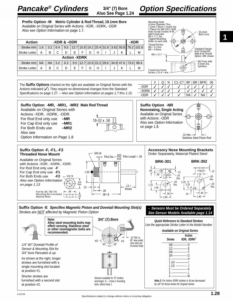
1
Specifications subject to change without notice or incurring obligation
Pancake® Cylinders
1.28
Option Specifications3/4" (7) BoreAlso See Page 1.24
4-22-04
V Q N C1–C7 BF BR BFR 06-XDR ✓ ✓ ✓ ✓ ✓ ✓ ✓ ✓
-XDRK ✓ ✓ ✓ ✓ ✓ ✓ ✓ ✓
-ODR ✓ ✓ ✓ ✓ NA ✓ NA ✓
The Suffix Options charted on the right are available on Original Series with theActions indicated (✓ ). They require no dimensional changes from the StandardSpecifications on page 1.27. – Also see Option Information on pages 1.7 thru 1.15.
Suffix Option -E Specifies Magnetic Piston and Dovetail Mounting Slot(s)Strokes are NOT affected by Magnetic Piston Option
Quick Reference to Standard StrokesUse the appropriate Stroke Letter in the Model Number
65° 65°
Sensors available for “D” strokes and longer. D – J have 2 mounting slots; others have 1.
#1#2.14" Ref. to 45° wire outlet;Zero stick-out of sensor body1/4" 60° Dovetail Profile of
Sensor & Mounting Slot for3/4" bore Pancakes & up.
As shown at the right, longerstrokes are furnished with asingle mounting slot locatedat position #1.
Shorter strokes arefurnished with a second slotat position #2.
3/4" (7) Bore
Note 2: For Action XDRK strokes A–M are decreasedby 1/8" for those shown for Original Series.
Available on Original SeriesAction
Stroke XDR, XDRK2
3/8 ---------------- D1/2 ---------------- E5/8 ---------------- F3/4 ---------------- G1 ------------------ H1 1/4 -------------- I1 1/2 ------------- J2 ------------------ K3 ------------------ L4 ------------------ M
– Sensors Must be Ordered SeparatelySee Sensor Models Available page 1.14
Note:Alloy steel mounting bolts mayeffect sensing. Stainless steelor other nonmagnetic bolts arerecommended.
Suffix Option -F, -F1, -F2Threaded Nose MountAvailable on Original Serieswith Actions -XDR, -XDRK, -ODR.For Rod End only use -FFor Cap End only use -F1For Both Ends use -F2Also see Option Informationon page 1.13
.13.38
.13 +Stroke
.38+ B
1.50
5/8-18Pilot Dia. = .620
.615Pilot Length = .06
5/8-18
.88
.25
3/4Hex
Part No. MC-700-195Mounting Nut is includedMaterial: Brass
.69.44
1.25.63 .20
Dia.
.12
.63Dia.
.901.80
1.001.75 1.25
.63
.20Dia.
.12
.63Dia.
.901.80
2.25
.25
1.25
Accessory Nose Mounting BracketsOrder Separately. Material Plated Steel
BRK-301 BRK-302
Prefix Option -M Metric Cylinder & Rod Thread, 19.1mm BoreAvailable on Original Series with Actions: -XDR, -XDRK, -ODRAlso see Option Information on page 1.7. 30.2mm
Bolt Circle
M5 Ports with 9.5mm Dia.Spotface
M5 x 12.7
Standard Female Rod Thread M5.Male Rod ThreadOption -MR shown
Mounting Holes4.3mm Diameter Thru7.2mm C'Bore x 3.6mm Dp.2 Places for M4 SHCS both ends Except Strokes H-M which have two M5 x 11.1 DpTapped Mounting Holes on each end.Thread PitchesM4 = 0.7mmM5 = 0.8mm
Conversion FactorInches x 25.4 = mm
Stroke mm 1.6 3.2 6.4 9.5 12.7 15.9 19.1 25.4 31.8 3.81 50.8 76.2 101.6
Stroke Letter A B C D E F G H I J K L M
Stroke mm NA NA 3.2 6.3 9.5 12.7 15.9 22.2 28.6 34.9 47.6 73.0 98.4
Stroke Letter A B C D E F G H I J K L M
Action -XDR & -ODR -XDR
10-32 x .50
.31 HexStainless Steel Piston Rod
Suffix Option -MR, -MR1, -MR2 Male Rod ThreadAvailable on Original Series withActions -XDR, -XDRK, -ODR.For Rod End only use –MRFor Cap End only use –MR1For Both Ends use –MR2Also seeOption Information on Page 1.8
Suffix Option -NRNonrotating, Single ActingAvailable on Original Serieswith Actions: -ODRAlso see Option Informationon page 1.8.
Action -XDRK

1
Pancake® Cylinders
Specifications subject to change without notice or incurring obligation
ModelNumberCode
Suffix OptionsBorePrefix Options Stroke Action
–D –121 –X MRLeave blank ifnone desired
Metric MSee pages 1.7, 1.31 & 1.34
Bore Code1 1/8" 121
28.5mm 121
HOW TO ORDER1. Under Stroke – select letter(s) for desired Series
and Stroke.
2. Under Bore – select 121 for 1 1/8" bore.Seven Other Bore Sizes are AvailableBore Bore Code See page1/2" -------------- 5 ----------------- 1.173/4" -------------- 7 ----------------- 1.231 5/8" ---------- 221 --------------- 1.352" -------------- 321 --------------- 1.412 1/2" ---------- 521 --------------- 1.473" -------------- 721 --------------- 1.534" ------------- 1221 -------------- 1.59
3. Under Action – select letter(s) for desired action.
4. Under Prefix & Suffix Options–select letter(s) for desired optionsand add to model number.
EXAMPLESD-121-X
Original Series, 1/2" stroke - 1 1/8" Bore -Single Rod, Double Acting
TD-121-X-MR“T” Series, 3/8" Stroke - 1 1/8" Bore -Single Rod, Double Acting - Male Rod Thread
Model Number1 1/8" (121) Bore
1.29
A complete library of cylinder CAD drawings is available from your local Fabco-Air Distributoror from the Fabco-Air web site – http://www.fabco-air.com
ActionSingle rod
Double acting -XDouble acting, NonrotatingInternal guide pins - 150 psi max -XKSingle acting, spring retracted -OSingle acting, spring extended -OP
Double rodDouble acting -XDRDouble acting, NonrotatingInternal guide pins - 150 psi max -XDRKSingle acting, spring retracted -ODR
See pages 1.5 & 1.6 for Action Information.See pages 1.30 & 1.33 for Standard Specifications
Grey shadingindicates sensors arenot available.Strokes are NOTaffected by magneticpiston Option “E”
Standard StrokesOriginal Series
Action XXK O
XDRXDRK ODR OP
Stroke1/8 A A A3/16 B B B1/4 C C C1/2 D* D D3/4 X X X1 E E E
1 1/4 F F F1 1/2 G G G1 3/4 H H –
2 I I –3 J – –4 K – –
“T” SeriesIncludes PTFEpiston bearing
XAction XK O OP
Stroke1/16 TB TB TB1/8 TC TC TC3/8 TD* TD TD5/8 TX TX TX7/8 TE TE TE
1 1/8 TF TF TF1 3/8 TG TG TG1 5/8 TH TH –1 7/8 TI TI –2 7/8 TJ – –3 7/8 TK – –
* Note – Sensors not available:D-121-XK, TD-121-XK, D-121-XDRK
6-22-02
Suffix Options
Male rod thread: Single rod -MRDouble rod, rod end -MRDouble rod, cap end -MR1Double rod, both ends -MR2
PTFE seals -TViton seals -VQuad seals -QExternal guide, nonrotating
for load guiding (See page 1.65) -GHydraulic: Standard cover -HHole thru double rod shaft: 1/8" hole -13
Plus size: 5/32" hole -16150 psi max
Finish: ProCoat™ (Electroless Nickel) -NStroke collar: 1/8" -C1
1/4" -C2 3/8" -C31/2" -C4 5/8" -C53/4" -C6 7/8" -C7
Sound limiters: Rod end -LFCap end -LRBoth ends -LFR
Rubber Bumpers: Rod end -BFCap end -BRBoth ends -BFR
Adjustable extend stroke(Full stroke adjustment is standard) -ASAdjustable retract stroke (Over 1"adjustment add desired length, e.g. -RS2) -RSClevis mount: Ports in-line with slot -PM
Ports 90° to slot -SMEye mount: Ports in-line with tang -EPM
Ports 90° to tang -ESMThreaded nose mount: Single rod -F
Double rod, rod end -FDouble rod, cap end -F1Double rod, both ends -F2
Magnetic piston & sensor mounting slot(s) -EOrder sensors separately. See page 1.14.Stroke length determines number of mountingslots. See page 1.14, 1.32, 1.34
See pages 1.3 – 1.15 for general optioninformation and pages 1.31, 1.32 & 1.34 foroption specifications of 1 1/8" bore models.

1
Specifications subject to change without notice or incurring obligation
Pancake® Cylinders
1.30
Standard Specifications1-1/8" (121) BoreSingle Rod
12-15-04
Note 1 Note 1
Note 1 Note 1 Note 1 Note 1
Note 1 Note 1 Note 1 Note 1
Original Series "T" Series
Action –OP Single Acting, Spring Extended
Action –XDouble Acting
Action –XKDouble ActingNonrotating
See page 1.16 forMounting Bolts.Push area = .97Pull area = .78Seal Kits for Series:Original = 121-SK-K"T" = 121-SKG-K
Note 1:Strokes J, K, TJ,& TK have two#10-32 x .50Tapped MountingHoles on each end.
Note 1:Strokes J, K, TJ,& TK have two#10-32 x .50Tapped MountingHoles on each end.
See page 1.16 forMounting Bolts.Push area = .99Pull area = .80Seal Kits for Series:Original = 121-SK"T" = 121-SKG
Action –OP Single Acting, Spring Extended
Action –O Single Acting, Spring Retracted
Action –XK Double Acting, Nonrotating
Action –X Double Acting Action –X Double Acting
Stroke, Inches 1/8 3/16 1/4 1/2 3/4 1 1 1/4 1 1/2 1 3/4 2 3 4 1/16 1/8 3/8 5/8 7/8 1 1/8 1 3/8 1 5/8 1 7/8 2 7/8 3 7/8Stroke, Letter A B C D X E F G H I J K TB TC TD TX TE TF TG TH TI TJ TK
B1 1.02 1.02 1.02 1.33 1.77 2.02 2.27 2.52 2.95 3.39 3.99 4.99 1.02 1.02 1.33 1.77 2.02 2.27 2.52 2.95 3.39 3.99 4.99E1 .38 .38 .38 .38 .63 .63 .63 .63 .63 .63 .63 .63 .38 .38 .38 .63 .63 .63 .63 .63 .63 .63 .63K1 .69 .69 .69 1.00 1.44 1.69 1.94 2.19 2.62 3.06 .69 .69 1.00 1.44 1.69 1.94 2.19 2.62 3.06Y1 .45 .45 .45 .67 .52 .52 .52 .52 .70 .89 .52 .52 .45 .45 .67 .52 .52 .52 .52 .70 .89 .52 .52Z1 .45 .45 .45 .67 1.27 1.52 1.77 2.02 2.45 2.89 3.49 4.49 .45 .45 .67 1.27 1.52 1.77 2.02 2.45 2.89 3.49 4.49
Weight, lb. .28 .27 .26 .37 .48 .54 .61 .67 .81 .95 1.08 1.35 .28 .27 .38 .49 .55 .62 .68 .82 .96 1.09 1.36
B2 1.02 1.02 1.02 1.33 1.77 2.02 2.27 2.52 2.95 3.39 3.99 4.99 1.02 1.02 1.33 1.77 2.02 2.27 2.52 2.95 3.39 3.99 4.99E2 .38 .38 .38 .38 .63 .63 .63 .63 .63 .63 .63 .63 .38 .38 .38 .63 .63 .63 .63 .63 .63 .63 .63K2 .69 .69 .69 1.00 1.44 1.69 1.94 2.19 2.62 3.06 .69 .69 1.00 1.44 1.69 1.94 2.19 2.62 3.06Y2 .45 .45 .45 .67 .52 .52 .52 .52 .70 .89 .52 .52 .45 .45 .67 .52 .52 .52 .52 .70 .89 .52 .52Z2 .45 .45 .45 .67 1.27 1.52 1.77 2.02 2.45 2.89 3.49 4.49 .45 .45 .67 1.27 1.52 1.77 2.02 2.45 2.89 3.49 4.49
Weight, lb. .28 .27 .26 .37 .49 .55 .62 .68 .83 .97 1.10 1.38 .28 .27 .38 .50 .56 .63 .69 .84 .98 1.11 1.39
B3 1.02 1.02 1.02 1.33 2.02 2.27 2.95 3.39 3.99 3.99 NA* NA* 1.02 1.02 1.33 2.02 2.27 2.95 3.39 3.99 3.99 NA* NA*E3 .38 .38 .38 .38 .63 .63 .63 .63 .63 .63 " " .38 .38 .38 .63 .63 .63 .63 .63 .63 " "K3 .69 .69 .69 1.00 1.69 1.94 2.62 3.06 " " .69 .69 1.00 1.69 1.94 2.62 3.06 " "Y3 .52 .52 .70 .89 .52 .52 " " .52 .52 .70 .89 .52 .52 " "Z3 .45 .45 .45 .67 1.52 1.77 2.45 2.89 3.49 3.49 " " .45 .45 .67 1.52 1.77 2.45 2.89 3.49 3.49 " "
Weight,. lb. .28 .28 .28 .34 .57 .63 .84 .98 1.15 1.15 " " .29 .29 .35 .58 .65 .85 .99 1.16 1.16 " "Preload, lb. 6.0 5.0 4.0 3.8 4.4 3.7 5.0 4.6 2.5 2.8 " " 5.0 4.0 3.8 4.4 3.7 5.0 4.6 2.5 2.8 " "End of Stroke, lb. 8.5 8.5 8.5 11.8 17.7 18.6 17.8 18.3 22.2 17.7 " " 8.5 8.5 11.8 17.7 18.6 17.8 18.3 22.2 17.7 " "
B4 1.40 1.46 1.52 2.08 3.02 3.52 4.45 5.14 NA* NA* NA* NA* 1.33 1.40 1.96 2.90 3.40 4.33 5.02 NA* NA* NA* NA*E4 .38 .38 .38 .38 .63 .63 .63 .63 " " " " .38 .38 .38 .63 .63 .63 .63 " " " "K4 .94 .94 .94 1.25 1.94 2.19 2.87 3.31 " " " " .94 .94 1.25 1.94 2.19 2.87 3.31 " " " "Y4 .58 .64 .70 1.17 1.27 1.52 1.95 2.39 " " " " .51 .58 1.05 1.15 1.40 1.83 2.27 " " " "Z4 .58 .64 .70 1.17 2.27 2.77 3.70 4.39 " " " " .51 .58 1.05 2.15 2.65 3.58 4.27 " " " "
Weight, lb. .37 .36 .36 .43 .63 .70 .91 1.00 " " " " .37 .37 .44 .65 .72 .92 1.10 " " " "Preload, lb. 6.0 5.0 4.0 3.5 3.9 3.3 2.5 4.3 " " " " 5.0 4.0 3.5 6.1 5.1 4.0 5.5 " " " "End of Stroke, lb. 8.5 8.5 8.5 11.5 17.1 18.2 16.8 18.1 " " " " 8.5 8.5 8.5 17.1 18.2 16.8 18.1 " " " "
Rod End Face VentRod End Face Vent
5/16-24 x E1Female Rod Thread
1.69 Bolt Circle .20 Dia. Thru.32 C'Bore x .19 Dp.for 2, #10 SHCSJ, K, TJ & TK SeeNote 1
1.99
7/16 x .11Wrench Flat
.50 Rod Dia.90°
.14
B1K1
1/8 NPT
Rod End Face
Y1Z1
Cap End Face
.13
Strokes A–D & TB–TD are Ported on Opposite Sides
5/16-24 x E2Female Rod Thread
1.69 Bolt Circle .20 Dia. Thru.32 C'Bore x .19 Dp.for 2, #10 SHCSJ, K, TJ & TK SeeNote 1
1.99
7/16 x .11Wrench FlatRandom Rotation
.50 Rod Dia.90°
.14
B2K2
1/8 NPT
Rod End Face
Y2Z2
Cap End Face
.13
RodRotationTolerance ± 1°
Strokes A–D & TB–TD are Ported on Opposite Sides
Action –O Single Acting, Spring Retracted
Note 1 Note 1
Action –OPSingle ActingSpring Extended
See page 1.16 forMounting Bolts.Pull area = .80See Chart for SpringForces: Preload& End of StrokeSeal Kits for Series:Original = 121-SK"T" = 121-SKG
5/16-24 x E4Female Rod Thread
1.69 Bolt Circle .20 Dia. Thru.32 C'Bore x .19 Dp.for 2, #10 SHCS
1.99
7/16 x .11Wrench Flat
.50 Rod Dia.90°
.14 + Stroke
B4K4
1/8 NPT
Rod End Face
Y4Z4
Cap End Face
.38
Strokes A–D & TB–TD are Ported on Opposite Sides
Action –OSingle ActingSpring Retracted
Note 1:Strokes H, I, TH & TI have two #10-32 x .50Tapped MountingHoles on each end.See page 1.16 forMounting Bolts.Push area = .99See chart for SpringForces: Preload andEnd of Stroke.Seal Kits for Series:Original = 121-SK"T" = 121-SKG
5/16-24 x E3Female Rod Thread
1.69 Bolt Circle .20 Dia. Thru.32 C'Bore x .19 Dp.for 2, #10 SHCSH, I, TH & TISee Note 1
.40 Rod End VentStrokes A–D & TB–TD
1.99
7/16 x .11Wrench Flat
.50 Rod Dia.
90°Rod EndFace
.14
B3 K3
1/8 NPT
Rod End VentStrokes X–I& TX–TIY3
Z3
Cap End Face.13
Action –XK Double Acting, Nonrotating
N/A* = Not Available
NA* = Not Available

1
Pancake® Cylinders
Specifications subject to change without notice or incurring obligation1.31
Option Specifications1-1/8" (121) BoreAlso See Pg. 1.30
T V Q H N C1–C7 LF LR LFR BF BR BFR-X ✓ ✓ ✓ ✓ ✓ ✓ ✓ ✓ ✓ ✓ ✓ ✓
-XK NA ✓ ✓ NA ✓ ✓ NA ✓ NA ✓ ✓ ✓-O NA ✓ ✓ ✓ ✓ NA NA ✓ NA NA ✓ NA
-OP NA ✓ ✓ ✓ ✓ ✓ ✓ ✓ ✓ ✓ NA NA
The Suffix Options charted on the right are available on Originaland “T” Series with the Actions indicated (✓ ). They require nodimensional changes from the Standard Specifications on page1.30. – Also see Option Information on pages 1.7 thru 1.15.
.37
.57
Oil filled bushing
.81 + B
.56
.30
-EPMPort LocationIN LINE with Tang
-ESMPort Location90° to Tang
See Page 1.30
.3135
1.00
Suffix Options -EPM & -ESM Eye MountAvailable on Original and “T” Serieswith Actions: -X, -XK, -O, -OPAlso see Option Information on page 1.13.
.37
.69
1.00
Oil filled bushings
.81 + B
.56
.31 1.21
-PMPort LocationIN LINE with Slot -SM
Port Location90° to Slot
See Page 1.30
Note 1
Note 1:Hole Diameter = .3135Pin Diameter = .3125Pin (416 Stainless Steel) and Clips are included
Suffix Options -PM & -SM Clevis MountAvailable on Original and “T” Serieswith Actions: -X, -XK, -O, -OPAlso see Option Information on page 1.13.
Prefix Option -M Metric Cylinder & Rod Thread, 28.5mm BoreAvailable on Original and “T” Series with Actions: -X, -XK, -O, -OPAlso see Option Information on page 1.7. 42.8mm Bolt Circle
G1/8 Ports with 14mm Spotface
M8 x 19.0
Standard Female Rod Thread M8.Male Rod ThreadOption -MR shown.
Mounting Holes5.3mm Diameter Thru8.8mm C'Bore x 5.3mm Dp.2 Places for M5 SHCSExcept strokes J, K, TJ& TK which havetwo M5 x 12.0mm Dp.Tapped Mounting Holes on each end.
Thread PitchesM5 = 0.8mmM8 = 1.25mm
Conversion FactorInches x 25.4 = mm
Stroke mm 3.2 4.8 6.4 12.7 19.1 25.4 31.8 38.1 44.5 50.8 76.2 101.6
Stroke Letter A B C D X E F G H I J K
Stroke mm 1.6 3.2 9.5 15.9 22.2 28.6 34.9 41.3 47.6 73.0 96.4Stroke Letter TB TC TD TX TE TF TG TH TI TJ TK
Original Series
“T” Series
12-15-04
EM-04 Eye Bracket KitMates RC-31Rod Clevis shownon the left.
EM-121 Eye Bracket KitMates with Clevis Mount above.Order separately.
RC-31 Rod Clevis and PinThreaded Stud mates withFemale Rod threadin Pancake® Cylinders.Slot & Pin Mate withEM-04 Eye Bracketshown on the right.
Materials:Clevis – Steel, Black OxideStud – SteelPin – 416 Stainless SteelPin & Clips are included
.25
Pin Diameter .250
5/16-24Optional Metric#MRC-31M8 x 9.7mm
1.16
.88
.96 .50 .39
.75
PM-121 Clevis Bracket KitMates with Eye Mount above.Order separately.
.88 1.131.50
.941.32
Hole .3135Pin .3125 Pin (416 StainlessSteel) & Clipsare included. Oil Filled Bushingsare Standard.
.69.46
1.211.00
.27 Dia. 4 Placeson Square Patternfor Flat Head Screws.Four 1/4-20 x 3/4"FH(#12)M Screwsare included.
.31
.25 Material:Zinc Die Casting
.44.69
1.38
.25
1.50
1.501.13
Hole .3135Oil filled bushingis standard
.30
1.13 .94.27 Dia. 4 Placesfor Flat Head ScrewsFour 1/4-20 x 3/4"FH(#12)M Screwsare included
Material: Zinc Die Casting
.31.41
.87
.16
1.25
1.25.88
Hole .251Oil filled bushingis standard
.23
.88 .56.27 Dia. 4 Placesfor Flat Head ScrewsFour 1/4-20 x 3/4"FH(#12)M Screws are included
Material: Zinc Die Casting

1
Specifications subject to change without notice or incurring obligation
Pancake® Cylinders
1.32
Option Specifications1-1/8" (121) BoreAlso See Pg. 1.30
40° 40° #1#2
Sensors available for “D” & “TD” strokes and longer. D – F & TD – TF have 2 mounting slots; others have 1. Strokes A – D & TB – TD are ported on opposite sides.
1 1/8" (121) Bore
Suffix Option -E Specifies Magnetic Piston and Dovetail Mounting Slot(s)Strokes are NOT affected by magnetic piston.
Quick Reference to Standard StrokesUse the appropriate Stroke Letter in the Model Number
1/4" 60° Dovetail Profile ofSensor & Mounting Slot for3/4" bore Pancakes & up.
As shown at the right, longerstrokes are furnished with asingle mounting slot located atposition #1.
Shorter strokes are furnishedwith a second slot at position #2.
Available on Original Series Action
Stroke X XK
1/2 ------------ D ----- Not Available3/4 ------------ X ------------ X1 -------------- E ------------ E1 1/4 --------- F ------------ F1 1/2 --------- G ------------ G1 3/4 --------- H ------------ H2 --------------- I -------------- I3 -------------- J ------------ J4 -------------- K ------------ K
Available on“T” Series Action
Stroke X XK3/8 --------- TD ---- Not Available5/8 ---------- TX ---------- TX7/8 ---------- TE ---------- TE1 1/8 -------- TF ---------- TF1 3/8 ------- TG --------- TG1 5/8 ------- TH ----------TH1 7/8 -------- TI ---------- TI2 7/8 ------- TJ ---------- TJ3 7/8 -------- TK ---------- TK
– Sensors Must be Ordered SeparatelySee Sensor Models Available page 1.14
Note:Alloy steel mounting bolts mayeffect sensing. Stainless steelor other nonmagnetic bolts arerecommended.
Suffix Option -AS Adjustable Extend StrokeAvailable on Original Series with Actions: -X, -XK, -OAlso see Option Information on page 1.11.
BB C
ED
1.50 Dia.
1.13 Dia. .050 Stroke AdjustmentPer Revolution
Stroke Inches 1/8 3/16 1/4 1/2 3/4 1 1-1/4 1-1/2 1-3/4 2 3 4Stroke Letter A B C D X E F G H I J K
Actions: -X, -XK BB 1.36 1.36 1.36 1.67 2.11 2.36 2.61 2.86 3.30 3.74 4.33 5.33Actions:-O BB 1.36 1.36 1.36 1.67 2.36 2.61 3.30 3.74 4.33 4.33 NA NA
C 1.40 1.53 1.66 2.16 2.66 3.16 3.66 4.16 4.66 5.16 7.16 9.16D 0.63 0.69 0.75 1.00 1.25 1.50 1.75 2.00 2.25 2.50 3.50 4.50E 0.63 0.69 0.75 1.00 1.25 1.50 1.75 2.00 2.25 2.50 3.50 4.50
Suffix Option -RS Adjustable Retract StrokeAvailable on Original and “T” Serieswith Actions: -X, -XK, -O, -OPAlso see Option Information on page 1.11.
Suffix Option -MR Male Rod ThreadAvailable on Originaland “T” Series withActions: -X, -XK, -O, -OP.Also see Option Informationon page 1.8.
.17
.13 + B(-OP Only Use B4 as shown on page 1.30. No additional length is required.)
9/16 Hex Nut
.042 Stroke AdjustmentPer Revolution
Adjusting Screw
Strokes 1" & Shorter = .38 Max. + StrokeStrokes 1" & Longer = .38 + AdjustmentStandard Adjustment is 1"
5/16-24 x 0.75
Suffix Option -F Threaded Nose MountAvailable on Original and “T” Serieswith Actions: -X, -XK, -O, -OPAlso see Option Informationon page 1.13.
1-14
1.59
.19
1 3/8Hex
Part No. 12100-195Mounting Nut is includedMaterial: Zinc Plated Steel
.14
.25
.75
1.00+ B
1.99
Pilot Dia. = 1.000.995
Pilot Length = .13
1-14
4-22-04

1
Pancake® Cylinders
Specifications subject to change without notice or incurring obligation1.33
1-1/8" (121) BoreDouble Rod
Standard Specifications
4-22-04
Action –XDR Original SeriesDouble Rod, Double Acting
Action –XDRK Original SeriesDouble Rod, Double Acting, Nonrotating
Action –ODR Original SeriesDouble Rod, Single Acting, Spring Retracted
Stroke, Inches 1/8 3/16 1/4 1/2 3/4 1 1 1/4 1 1/2 1 3/4 2 3 4Stroke, Letter A B C D X E F G H I J K
B 1.36 1.36 1.36 1.67 2.11 2.36 2.61 2.86 3.30 3.74 4.33 5.33E .38 .38 .38 .34 .63 .63 .63 .63 .63 .63 .63 .63K 1.04 1.04 1.04 1.34 1.78 2.03 2.28 2.53 2.96 3.40Y .45 .45 .45 .67 .52 .52 .52 .52 .70 .89 .52 .52Z .45 .45 .45 .67 1.27 1.52 1.77 2.02 2.45 2.89 3.49 4.49
Weight, lb. .46 .45 .44 .55 .68 .76 .83 .91 1.07 1.22 1.41 1.71
Note 1 Note 1
Stroke, Inches 1/8 3/16 1/4 1/2 3/4 1 1 1/4 1 1/2 1 3/4 2 3 4Stroke, Letter A B C D X E F G H I J K
B 1.36 1.36 1.36 1.67 2.11 2.36 2.61 2.86 3.30 3.74 4.33 5.33E .38 .38 .38 .34 .63 .63 .63 .63 .63 .63 .63 .63K 1.04 1.04 1.04 1.34 1.78 2.03 2.28 2.53 2.96 3.40Y .45 .45 .45 .67 .52 .52 .52 .52 .70 .89 .52 .52Z .45 .45 .45 .67 1.27 1.52 1.77 2.02 2.45 2.89 3.49 4.49
Weight, lb. .47 .46 .45 .56 .69 .77 .84 .93 1.09 1.24 1.43 1.74
Note 1 Note 1
Note 1 Note 1Rod End Vent Face
Stroke, Inches 1/8 3/16 1/4 1/2 3/4 1 1 1/4 1 1/2 1 3/4 2Stroke, Letter A B C D X E F G H I
B 1.36 1.36 1.36 1.67 2.36 2.61 3.30 3.74 4.33 4.33E .38 .38 .38 .34 .63 .63 .63 .63 .63 .63K 1.04 1.04 1.04 1.34 2.03 2.28 2.96 3.40Y .52 .52 .70 .89 .52 .52Z .45 .45 .45 .67 1.52 1.77 2.45 2.89 3.49 3.49
Weight, lb. .44 .44 .43 .53 .76 .83 1.07 1.22 1.41 1.41Spring Return Forces, lb.
Preload 6.0 5.0 4.0 3.5 4.4 3.7 2.8 4.6 2.8 2.8End of Stroke 8.5 8.5 8.5 11.5 17.7 18.6 17.1 18.3 15.8 17.7
Note 1:Strokes J & K havetwo #10-32 x .50Tapped MountingHoles on each end.
Note 1:Strokes J & K havetwo #10-32 x .50Tapped MountingHoles on each end.
Note 1:Strokes H & I havetwo #10-32 x .50Tapped MountingHoles on each end.
See page 1.16 forMounting BoltsForce Area = .80Seal Kit = 121-SK
See page 1.16 forMounting BoltsForce Area = .78Seal Kit = 121-SK-K
See page 1.16 forMounting BoltsForce Area = .80Seal Kit = 121-SK
5/16-24 x EFemale Rod Thread
1.69 Bolt Circle .20 Dia. Thru.32 C'Bore x .19 Dp.for 2, #10 SHCSJ & K See Note 1
1.997/16 x .11Wrench FlatRandomRotation
.50 Rod Dia.90°
.14
BK
1/8 NPT
Rod End Face
YZ
Cap End Face
.47
Strokes A – D are Ported on Opposite Sides
.14 + Stroke
RodRotationTolerance± 1°
5/16-24 x EFemale Rod Thread
1.69 Bolt Circle .20 Dia. Thru.32 C'Bore x .19 Dp.for 2, #10 SHCSJ & K See Note 1
1.99
7/16 x .11Wrench Flat
.50 Rod Dia.90°
.14
BK
1/8 NPT
Rod End Face
YZ
Cap End Face
.47
Strokes A – D are Ported on Opposite Sides
.14 + Stroke
5/16-24 x EFemale Rod Thread
1.69 Bolt Circle .20 Dia. Thru.32 C'Bore x .19 Dp.for 2, #10 SHCSH & I See Note 1
1.99
7/16 x .11Wrench Flat
.50 Rod Dia.
90°
.14
BK
1/8 NPT
Rod End Face
YZ
Cap End Face
.47
.14 + Stroke
Rod End VentStrokes X – I
.40 Rod End VentStrokes A – D

1
Specifications subject to change without notice or incurring obligation
Pancake® Cylinders
1.34
1-1/8" (121) BoreAlso See Pg. 1.33
Option Specifications
The Suffix Options charted on the right are available onOriginal Series with the Actions indicated (✓ ). They require nodimensional changes from the Standard Specifications on page1.33. – Also see Option Information on pages 1.7 thru 1.15.
T V Q H N C1–C7 LF LR LFR BF BR BFR 13 16-XDR ✓ ✓ ✓ ✓ ✓ ✓ ✓ ✓ ✓ ✓ ✓ ✓ ✓ ✓
-XDRK NA ✓ ✓ NA ✓ ✓ NA NA NA ✓ ✓ ✓ ✓ ✓-ODR NA ✓ ✓ ✓ ✓ NA NA ✓ NA NA ✓ NA ✓ ✓
Quick Reference to Standard StrokesUse the appropriate Stroke Letter in the Model Number
40° 40° #1#2
Sensors available for “D” strokes and longer. D – F have 2 mounting slots; others have 1. Strokes A – Dare ported on opposite sides.
1/4" 60° Dovetail Profile ofSensor & Mounting Slot for3/4" bore Pancakes & up.
As shown at the right, longerstrokes are furnished with asingle mounting slot locatedat position #1.
Shorter strokes arefurnished with a second slotat position #2.
1 1/8" (121) Bore
Available on Original Series Action
Stroke XDR XDRK
1/2 ------------ D ----- Not Available3/4 ------------ X ------------ X1 -------------- E ------------ E1 1/4 --------- F ------------ F1 1/2 --------- G ------------ G1 3/4 --------- H ------------ H2 --------------- I -------------- I3 -------------- J ------------ J4 -------------- K ------------ K
Suffix Option -E Specifies Magnetic Piston and Dovetail Mounting Slot(s) –Sensors Must Be Ordered SeparatelyStrokes are NOT affected by magnetic piston. See Sensor Models Available page 1.14
Note:Alloy steel mounting bolts mayeffect sensing. Stainless steelor other nonmagnetic bolts arerecommended.
Suffix Options -MR, -MR1, -MR2 Male Rod Thread
Available on Original Series with Actions -XDR, -XDRK, -ODR.
For Rod End only use –MRFor Cap End only use –MR1For Both Ends use –MR2
Also see Option Information on Page 1.8.
5/16-24 x 0.75
Prefix Option -M Metric Cylinder & Rod Thread, 50.8mm BoreAvailable on Original Series with Actions: -XDR, -XDRK, -ODRAlso see Option Information on page 1.7.
42.8mm Bolt Circle
G1/8 Ports with 14mm Spotface
M8 x 19.0
Standard Female Rod Thread M8.Male Rod ThreadOption -MR shown.
Mounting Holes5.3mm Diameter Thru8.8mm C'Bore x 5.3mm Dp.2 Places for M5 SHCSExcept strokes J & K which havetwo M5 x 12.0mm DpTapped Mounting Holes on each end.
Thread PitchesM5 = 0.8mmM8 = 1.25mm
Conversion FactorInches x 25.4 = mm
Stroke mm 3.2 4.8 6.4 12.7 19.1 25.4 31.8 38.1 44.5 50.8 76.2 101.6
Stroke Letter A B C D X E F G H I J K
4-22-04
Suffix Options -F, -F1, -F2 Threaded Nose MountAvailable on Original Serieswith Actions -XDR, -XDRK, -ODR.For Rod End only use -FFor Cap End only use -F1For Both Ends use -F2
Also see Option Information page 1.13.
.14 .25.75
.14 +Stroke
1.00+ B
1.99
Pilot Dia. = 1.000.995
Pilot Length = .13
1-141-14
1.59
.19
1 3/8Hex
Part No. 12100-195Mounting Nut is includedMaterial: Zinc Plated Steel

1
Pancake® Cylinders
Specifications subject to change without notice or incurring obligation
ModelNumberCode
Suffix OptionsBorePrefix Options Stroke Action
–D –221 – MRLeave blank ifnone desired
Metric MSee pages 1.7, 1.37 & 1.40
Bore Code1 5/8" 221
41.3mm 221
X
Model Number1 5/8" (221) Bore
1.35 6-3-02
A complete library of cylinder CAD drawings is available from your local Fabco-Air Distributoror from the Fabco-Air web site – http://www.fabco-air.com
HOW TO ORDER1. Under Stroke – select letter(s) for desired Series
and Stroke.
2. Under Bore – select 221 for 1 5/8" bore.Seven Other Bore Sizes are AvailableBore Bore Code See page1/2" -------------- 5 ----------------- 1.173/4" -------------- 7 ----------------- 1.231 1/8" ---------- 121 --------------- 1.292" -------------- 321 --------------- 1.412 1/2" ---------- 521 --------------- 1.473" -------------- 721 --------------- 1.534" ------------- 1221 -------------- 1.59
3. Under Action – select letter(s) for desired action.
4. Under Prefix & Suffix Options–select letter(s) for desired optionsand add to model number.
EXAMPLESB-221-X
Original Series, 1/2" stroke - 1 5/8" Bore -Single Rod, Double Acting
TC-221-O-MR“T” Series, 1/2" Stroke - 1 5/8" Bore -Single Rod, Spring Retract - Male Rod Thread
Grey shadingindicates sensorsare not available.
Strokes are NOTaffected by magneticpiston Option “E”
Standard Strokes
Original SeriesX
Action XKXDR OXDRK ODR OP
Stroke1/8 AA AA AA1/4 A* A A1/2 B B B3/4 C C C1 D D D
1 1/2 E E –2 F – –3 G – –4 H – –
“T” SeriesIncludes PTFEpiston bearing
XAction XK O OPStroke
1/4 TB TB TB1/2 TC TC TC3/4 TD TD TD
1 1/4 TE TE –1 3/4 TF – –2 3/4 TG – –3 3/4 TH – –
ActionSingle rod
Double acting -XDouble acting, NonrotatingInternal guide pins - 150 psi max -XKSingle acting, spring retracted -OSingle acting, spring extended -OP
Double rodDouble acting -XDRDouble acting, NonrotatingInternal guide pins - 150 psi max -XDRKSingle acting, spring retracted -ODR
See pages 1.5 & 1.6 for Action Information.See pages 1.36 & 1.39 for Standard Specifications
See pages 1.3 – 1.15 for general option information.and pages 1.37, 1.38 & 1.40 for option specificationsof 1 5/8" bore models.
Suffix Options
Male rod thread: Single rod -MRDouble rod, rod end -MRDouble rod, cap end -MR1Double rod, both ends -MR2
PTFE seals -TViton seals -VQuad seals -QExternal guide, nonrotating
for load guiding (See page 1.65) -G
Hydraulic:Standard cover -HThick cover -HHC
Air service: Thick cover -HC1/4 NPT ports -P14Hole thru double rod shaft: 1/8" hole -13
Plus size: 1/4" hole -25150 psi max
Finish: ProCoat™ (Electroless Nickel) -NStroke collar: 1/8" -C1
1/4" -C2 3/8" -C31/2" -C4 5/8" -C53/4" -C6 7/8" -C7
Sound limiters: Rod end -LFCap end -LRBoth ends -LFR
Rubber Bumpers: Rod end -BFCap end -BRBoth ends -BFR
Adjustable extend stroke(Full stroke adjustment is standard) -ASAdjustable retract stroke (Over 1"adjustment add desired length, e.g. -RS2) -RSClevis mount: Ports in-line with slot -PM
Ports 90° to slot -SMEye mount: Ports in-line with tang -EPM
Ports 90° to tang -ESMThreaded nose mount: Single rod -F
Double rod, rod end -FDouble rod, cap end -F1Double rod, both ends -F2
Magnetic piston & sensor mounting slot(s) -EOrder sensors separately. See page 1.14.Stroke length determines number ofmounting slots. See page 1.14, 1.38, 1.40
*Note –Sensors not available:A-221-XKA-221-XDRK

1
Specifications subject to change without notice or incurring obligation
Pancake® Cylinders
1.36
1-5/8" (221) BoreSingle Rod
Standard Specifications
Action –X Double Acting
Action –O Single Acting, Spring Retracted
4-22-04
Original Series "T" Series
Action –OSingle ActingSpring Retracted
Action –OPSingle ActingSpring Extended
Action –XDouble Acting
Action –XKDouble ActingNonrotating
See page 1.16 forMounting Bolts.Push area = 2.01Pull area = 1.70Seal Kits for Series:Original = 221-SK-K"T" = 221-SKG-K
See page 1.16 forMounting Bolts.Push area = 2.07Pull area = 1.76Seal Kits for Series:Original = 221-SK"T" = 221-SKG
Action –OP Single Acting, Spring Extended
Action –O Single Acting, Spring Retracted
Action –XK Double Acting, Nonrotating
Action –X Double Acting
3/8-24 x E3Female Rod Thread
2.38 Bolt Circle .20 Dia. Thru.32 C'Bore x .19 Dp.for 2, #10 SHCS
2.741/2 x .11Wrench Flat
.62 Rod Dia.
.14
B3 K3
1/8 NPT
Rod End Face
Y3Z3
Cap End Face
.13
.66 Rod End VentStrokes AA-D & TB - TD
Rod End VentStrokes E & TE
90°
Rod End Face VentRod End Face Vent
See page 1.16 forMounting Bolts.Pull area = 1.76See Chart for SpringForces: Preload& End of StrokeSeal Kits for Series:Original = 221-SK"T" = 221-SKG
3/8-24 x E1Female Rod Thread2.38 Bolt Circle .20 Dia. Thru.32 C'Bore x .19 Dp.for 2, #10 SHCS
2.741/2 x .11Wrench Flat
.62 Rod Dia..14
B1K1
1/8 NPT
Rod End Face
Y1Z1
Cap End Face
.13
Strokes AA–A are Ported on Opposite Sides
90°
3/8-24 x E2Female Rod Thread
2.38 Bolt Circle .20 Dia. Thru.32 C'Bore x .19 Dp.for 2, #10 SHCS
2.741/2 x .11Wrench FlatRandom Rotation
.62 Rod Dia.
.14
B2K2
1/8 NPT
Rod End Face
Y2Z2
Cap End Face
.25
RodRotationTolerance ± 1°
Strokes AA–A are Ported on Opposite Sides
90°
3/8-24 x E4Female Rod Thread
2.38 Bolt Circle .20 Dia. Thru.32 C'Bore x .19 Dp.for 2, #10 SHCS
2.741/2 x .11Wrench Flat
.62 Rod Dia.
.14 + Stroke
B4K4
1/8 NPT
Y4Z4
Cap End Face
For StrokesAA-C = .50D = .63TB-TC = .50TD = .63
Strokes AA–A are Ported on Opposite Sides
Rod End Face90°
NA* = Not Available
Stroke, Inches 1/8 1/4 1/2 3/4 1 1 1/2 2 3 4 1/4 1/2 3/4 1 1/4 1 3/4 2 3/4 3 3/4Stroke, Letter AA A B C D E F G H TB TC TD TE TF TG TH
B1 1.14 1.27 1.77 2.02 2.33 2.83 3.33 4.33 5.33 1.77 2.02 2.33 2.83 3.33 4.33 5.33E1 .38 .44 .63 .63 .75 .75 .75 .75 .75 .63 .63 .75 .75 .75 .75 .75K1 .81 .94 1.44 1.69 2.00 2.50 3.00 4.00 5.00 1.44 1.69 2.00 2.50 3.00 4.00 5.00Y1 .64 .64 .52 .52 .52 .52 .52 .52 .52 .52 .52 .52 .52 .52 .52 .52Z1 .64 .64 1.27 1.52 1.83 2.33 2.83 3.83 4.83 1.27 1.57 1.83 2.33 2.83 3.83 4.83
Weight, lb. .60 .64 .93 1.06 1.19 1.43 1.66 2.14 2.60 .99 1.12 1.25 1.49 1.72 2.20 2.66
B2 1.27 1.40 1.90 2.15 2.46 2.96 3.46 4.46 5.46 1.90 2.15 2.46 2.96 3.46 4.46 5.46E2 .38 .44 .63 .63 .75 .75 .75 .75 .75 .63 .63 .75 .75 .75 .75 .75K2 .94 1.06 1.57 1.82 2.13 2.63 3.13 4.13 5.13 1.57 1.82 2.13 2.63 3.13 4.13 5.13Y2 .64 .64 .52 .52 .52 .52 .52 .52 .52 .52 .52 .52 .52 .52 .52 .52Z2 .64 .64 1.27 1.52 1.83 2.33 2.83 3.83 4.83 1.27 1.57 1.83 2.33 2.83 3.83 4.83
Weight, lb. .68 .72 1.02 1.15 1.29 1.53 1.77 2.27 2.74 1.08 1.21 1.35 1.59 1.83 2.83 3.80
B3 1.14 1.27 1.77 2.02 2.33 4.33 NA* NA* NA* 1.77 2.02 2.33 4.33 NA* NA* NA*E3 .38 .44 .63 .63 .75 .75 NA* NA* NA* .63 .63 .75 .75 NA* NA* NA*K3 .81 .94 1.44 1.69 2.00 4.00 NA* NA* NA* 1.44 1.69 2.00 4.00 NA* NA* NA*Y3 .52 NA* NA* NA* .52 NA* NA* NA*Z3 .64 .77 1.27 1.52 1.83 3.83 NA* NA* NA* 1.27 1.57 1.83 3.83 NA* NA* NA*
Weight,. lb. .58 .63 .89 1.00 1.15 2.10 NA* NA* NA* .95 1.06 1.21 2.16 NA* NA* NA*Preload, lb. 15.0 8.5 8.5 6.0 4.8 6.0 NA* NA* NA* 8.5 8.5 6.0 7.06 NA* NA* NA*End of Stroke, lb. 20.0 20.0 20.0 18.0 20.0 18.0 NA* NA* NA* 20.0 20.0 18.0 20.0 NA* NA* NA*
B4 1.65 1.89 2.64 3.14 3.83 NA* NA* NA* NA* 2.39 2.89 3.58 NA* NA* NA* NA*E4 .38 .44 .63 .63 .75 NA* NA* NA* NA* .63 .63 .75 NA* NA* NA* NA*K4 1.19 1.32 1.82 2.07 2.50 NA* NA* NA* NA* 1.82 2.07 2.50 NA* NA* NA* NA*Y4 .77 .89 1.02 1.27 1.52 NA* NA* NA* NA* .77 1.02 1.27 NA* NA* NA* NA*Z4 .77 .89 1.77 2.27 2.83 NA* NA* NA* NA* 1.52 2.07 2.58 NA* NA* NA* NA*
Weight, lb. .81 .83 1.10 1.20 1.42 NA* NA* NA* NA* 1.16 1.26 1.48 NA* NA* NA* NA*Preload, lb. 8.5 4.5 5.5 4.0 4.8 NA* NA* NA* NA* 4.5 5.5 4.0 NA* NA* NA* NA*End of Stroke, lb. 15.0 15.0 18.5 17.5 20.0 NA* NA* NA* NA* 15.0 18.5 17.5 NA* NA* NA* NA*
Action –XK Double Acting, Nonrotating
Action –OP Single Acting, Spring Extended
See page 1.16 forMounting Bolts.Push area = 2.07See Chart for SpringForces: Preload& End of StrokeSeal Kits for Series:Original = 221-SK"T" = 221-SKG

1
Pancake® Cylinders
Specifications subject to change without notice or incurring obligation1.37
Option Specifications1-5/8" (221) BoreAlso See Page 1.36
.37
.60
Oil filled bushing
Chart
.68
.35
-EPMPort LocationIN LINE with Tang
-ESMPort Location90° to Tang
Also see page 1.36
.376
1.25
ChartAction-X, -O-XK-OP-OP
DimensionAll Strokes .88 + BAll Strokes .75 + B
AA-C Strokes .94 + BD Stroke .81 + B
.37
.69
1.25
Oil filled bushings
Chart
.68
.38 1.48
-PMPort LocationIN LINE with Slot -SM
Port Location90° to Slot
Also see page 1.36
Note 1
Pin (416 Stainless Steel) & Clips are included
ChartAction-X, -O-XK-OP-OP
DimensionAll Strokes .88 + BAll Strokes .75 + B
AA-C Strokes .94 + BD Stroke .81 + B
Note 1:Hole Diameter = .376Pin Diameter = .3750
12-15-04
Suffix Options -PM & -SM Clevis MountAvailable on Original and “T” Serieswith Actions: -X, -XK, -O, -OPAlso see Option Information on page 1.13.
Suffix Options -EPM & -ESM Eye MountAvailable on Original and “T” Serieswith Actions: -X, -XK, -O, -OPAlso see Option Information on page 1.13.
Prefix Option -M Metric Cylinder & Rod Thread, 41.3mm BoreAvailable on Original and “T” Series with Actions: -X, -XK, -O, -OPAlso see Option Information on page 1.7. 60.3mm Bolt Circle
G1/8 Ports with 14mm Spotface
M10 x 22.2
Standard Female Rod Thread M10.Male Rod ThreadOption -MR shown.
Mounting Holes5.3mm Diameter Thru8.8mm C'Bore x 5.3mm Dp.2 Places for M5 SHCS
Thread PitchesM5 = 0.8mmM10 = 1.5mm
Conversion FactorInches x 25.4 = mm
Stroke mm 3.2 6.4 12.7 19.1 25.4 38.1 50.8 76.2 101.6
Stroke Letter AA A B C D E F G H
Stroke mm 6.4 12.7 19.1 31.8 44.5 69.9 95.3Stroke Letter TB TC TD TE TF TG TH
Original Series
“T” Series
EM-121 Eye Bracket KitMates RC-38Rod Clevis shownon the left.
EM-221 Eye Bracket KitMates with Clevis Mountshown above.Order separately.
RC-38 Rod Clevis and PinThreaded Stud mates withFemale Rod thread in Pancake®
Cylinders. Slot & Pin Mate withEM-121 Eye Bracket shownon the right.
.32
Pin Diameter .3125
3/8-24 x .37Optional Metric#MRC-38M10 x 9.4
1.63
1.25
1.21 .63 . 61
1.00
Materials:Clevis – Steel, Black OxideStud – SteelPin – 416 Stainless SteelPin & Clips are included
PM-221 Clevis Bracket KitMates with Eye Mountshown above.Order separately. 1.25 1.50
2.00
1.001.38
Hole .376Pin .3750Pin (416StainlessSteel) & Clipsincluded. Oil Filled Bushingsare Standard.
.69.52
1.481.25
.27 Dia. 4 Placeson Square Patternfor Flat Head Screws.Four 1/4-20 x 1"FHSCS Screwsare included.
.38
.31Material:Zinc Die Casting
.56.81
1.69
.31
2.00
2.001.50
Hole .376Oil filled bushingis standard
.36
1.50 1.13.27 Dia. 4 Placesfor Flat Head ScrewsFour 1/4-20 x 1"FHSCS Screwsare included
Material: Zinc Die Casting
.44.69
1.38
.25
1.50
1.501.13
Hole .3135Oil filled bushingis standard
.30
1.13 .94.27 Dia. 4 Placesfor Flat Head ScrewsFour 1/4-20 x 3/4"FH(#12)M Screwsare included
Material: Zinc Die Casting
The Suffix Options charted on the right are available on Originaland “T” Series with the Actions indicated (✓ ). They require nodimensional changes from the Standard Specifications on page1.36. – Also see Option Information on pages 1.7 thru 1.15.
T V Q H N C1–C7 LF LR LFR BF BR BFR P14-X ✓ ✓ ✓ ✓ ✓ ✓ ✓ ✓ ✓ ✓ ✓ ✓ ✓-XK NA ✓ ✓ NA ✓ ✓ NA ✓ NA ✓ ✓ ✓ ✓-O NA ✓ ✓ ✓ ✓ NA NA ✓ NA NA ✓ NA ✓-OP NA ✓ ✓ ✓ ✓ ✓ ✓ ✓ ✓ ✓ NA NA ✓

1
Specifications subject to change without notice or incurring obligation
Pancake® Cylinders
1.38
Option Specifications1-5/8" (221) BoreAlso See Page 1.36
45°45° #1#2
Sensors available for “A” & “TB” strokes and longer. A – D & TB – TD have 2 mounting slots; others have 1. Strokes AA – A are ported on opposite sides.
1 5/8" (221) Bore
1/4" 60° Dovetail Profile ofSensor & Mounting Slot for3/4" bore Pancakes & up.
As shown at the right, longerstrokes are furnished with asingle mounting slot locatedat position #1.
Shorter strokes arefurnished with a second slotat position #2.
Suffix Option -E Specifies Magnetic Piston and Dovetail Mounting Slot(s)
Quick Reference to Standard StrokesUse the appropriate Stroke Letter in the Model Number
Available on Original Series
ActionStroke X XK
1/4 --------------- A ----- Not Available1/2 --------------- B ------------- B3/4 --------------- C ------------- C1 ----------------- D ------------- D1 1/2 ------------ E ------------- E2 ----------------- F ------------- F3 ----------------- G ------------- G4 ----------------- H ------------- H
Available on“T” SeriesAction
Stroke X, XK
1/4 -------------- TB1/2 -------------- TC3/4 -------------- TD1 1/4 ----------- TE1 3/4 ----------- TF2 3/4 ----------- TG3 3/4 ----------- TH
– Sensors Must be Ordered SeparatelySee Sensor Models Available page 1.14
4-22-04
Suffix Option -AS Adjustable Extend StrokeAvailable on Original Series with Actions: -X, -XK, -OAlso see Option Information on page 1.11.
BB C
ED
1.50 Dia.
1.13 Dia. .050 Stroke AdjustmentPer Revolution
Stroke Inches 1/8 1/4 1/2 3/4 1 1-1/2 2 3 4Stroke Letter AA A B C D E F G H
Actions: -X, -XK BB 1.61 1.74 2.24 2.49 2.80 3.30 3.80 4.80 5.80Actions:-O BB 1.61 1.74 2.24 2.49 2.80 4.80 NA NA NA
C 1.40 1.66 2.16 2.66 3.16 4.16 5.16 7.16 9.16D 0.63 0.75 1.00 1.25 1.50 2.00 2.50 3.50 4.50E 0.63 0.75 1.00 1.25 1.50 2.00 2.50 3.50 4.50
.14
.25
.75
1.00+ B
1.99
Pilot Dia. = 1.2501.245
Pilot Length = .13
1 1/4-12
Suffix Option -RS Adjustable Retract StrokeAvailable on Original and “T” Serieswith Actions: -X, -XK, -O, -OPAlso see Option Information on page 1.11.
Suffix Options -HHC Hydraulic & -HC AirAvailable on Original and “T” Series with Action -X, -O.
Also seeOption Informationon page 1.9 for Pressureand Mounting details.
Suffix Option -MR Male Rod ThreadAvailable on Originaland “T” Series withActions: -X, -XK, -O, -OP.Also see Option Informationon page 1.8.
.19
.13 + B(-XK Only Use B2 as shown on page 1.36. No additional length is required.)(-OP Only Use B4 as shown on page 1.36. No additional length is required.)
11/16 Hex Nut
.050 Stroke AdjustmentPer Revolution
Adjusting Screw
Strokes 1" & Shorter = .38 Max. + StrokeStrokes 1" & Longer = .38 + AdjustmentStandard Adjustment is 1"
3/8-24 x 0.88.12 + B
.12 + K
.25
Suffix Option -F Threaded Nose MountAvailable on Original and “T” Serieswith Actions: -X, -XK, -O, -OPAlso see Option Informationon page 1.13.
1 1/4 -12
1.88
.25
1 5/8Hex
Part No. 22100-195Mounting Nut is includedMaterial: Zinc Plated Steel

1
Pancake® Cylinders
Specifications subject to change without notice or incurring obligation1.39
Standard Specifications1-5/8" (221) BoreDouble Rod
Action –XDR Original SeriesDouble Rod, Double Acting
Action –XDRK Original SeriesDouble Rod, Double Acting, Nonrotating
Action –ODR Original SeriesDouble Rod, Single Acting, Spring Retracted
Rod End Vent Face
Stroke, Inches 1/8 1/4 1/2 3/4 1 1 1/2Stroke, Letter AA A B C D E
B 1.61 1.74 2.24 2.49 2.80 4.80E .38 .44 .63 .63 .75 .75K 1.28 1.41 1.91 2.16 2.47 4.47Y .52Z .64 .77 1.27 1.52 1.83 3.83
Weight, lb. .95 1.01 1.30 1.42 1.58 1.86Spring Return Forces, lb.
Preload 15.0 8.5 8.5 6.0 4.8 6.0End of Stroke 20.0 20.0 20.0 18.0 20.0 18.0
Stroke, Inches 1/8 1/4 1/2 3/4 1 1 1/2 2 3 4Stroke, Letter AA A B C D E F G H
B 1.61 1.74 2.24 2.49 2.80 3.30 3.80 4.80 5.80E .38 .44 .63 .63 .75 .75 .75 .75 .75K 1.28 1.41 1.91 2.16 2.47 2.97 3.47 4.47 5.47Y .64 .64 .52 .52 .52 .52 .52 .52 .52Z .64 .64 1.27 1.52 1.83 2.33 2.83 3.83 4.83
Weight, lb. 1.05 1.11 1.44 1.55 1.73 2.01 2.30 2.86 3.42
Stroke, Inches 1/8 1/4 1/2 3/4 1 1 1/2 2 3 4Stroke, Letter AA A B C D E F G H
B 1.61 1.74 2.24 2.49 2.80 3.30 3.80 4.80 5.80E .38 .44 .63 .63 .75 .75 .75 .75 .75K 1.28 1.41 1.91 2.16 2.47 2.97 3.47 4.47 5.47Y .64 .64 .52 .52 .52 .52 .52 .52 .52Z .64 .64 1.27 1.52 1.83 2.33 2.83 3.83 4.83
Weight, lb. .97 1.03 1.35 1.46 1.63 1.91 2.19 2.73 3.28
4-22-04
See page 1.16 forMounting BoltsForce Area = 1.76Seal Kit = 221-SK
See page 1.16 forMounting BoltsForce Area = 1.70Seal Kit = 221-SK-K
See page 1.16 forMounting BoltsForce Area = 1.76Seal Kit = 221-SK
3/8-24 x EFemale Rod Thread2.38 Bolt Circle .20 Dia. Thru.32 C'Bore x .19 Dp.for 2, #10 SHCS
2.741/2 x .11Wrench FlatRandomRotation
.62 Rod Dia..14
BK
1/8 NPT
Rod End Face
YZ
Cap End Face
.60
Strokes AA–A are Ported on Opposite Sides
90°
.14 + Stroke
RodRotationTolerance± 1°
3/8-24 x EFemale Rod Thread2.38 Bolt Circle .20 Dia. Thru.32 C'Bore x .19 Dp.for 2, #10 SHCS
2.741/2 x .11Wrench Flat
.62 Rod Dia..14
BK
1/8 NPT
Rod End Face
YZ
Cap End Face
.60
Strokes AA–A are Ported on Opposite Sides
90°
.14 + Stroke
3/8-24 x EFemale Rod Thread
2.38 Bolt Circle .20 Dia. Thru.32 C'Bore x .19 Dp.for 2, #10 SHCS
2.74
1/2 x .11Wrench Flat
.62 Rod Dia.
.14
BK
1/8 NPT
Rod End Face
YZ
Cap End Face
.60
90°
.14 + Stroke
.66 Rod End VentStrokes AA–D
Rod End VentStroke E

1
Specifications subject to change without notice or incurring obligation
Pancake® Cylinders
1.40
Option Specifications1-5/8" (221) BoreAlso See Page 1.39
Suffix Options -F, -F1, -F2 Threaded Nose MountAvailable on Original Serieswith Actions -XDR, -XDRK, -ODR.For Rod End only use -FFor Cap End only use -F1For Both Ends use -F2Also see Option Informationon page 1.13.
The Suffix Options charted on the right are available onOriginal Series with the Actions indicated (✓ ). They require nodimensional changes from the Standard Specifications on page1.39. – Also see Option Information on pages 1.7 thru 1.15.
T V Q H N C1–C7 LF LR LFR BF BR BFR P14 13 25-XDR ✓ ✓ ✓ ✓ ✓ ✓ ✓ ✓ ✓ ✓ ✓ ✓ ✓ ✓ ✓
-XDRK NA ✓ ✓ NA ✓ ✓ NA ✓ NA ✓ ✓ ✓ ✓ ✓ ✓-ODR NA ✓ ✓ ✓ ✓ NA NA ✓ NA NA ✓ NA ✓ ✓ ✓
1/4" 60° Dovetail Profile ofSensor & Mounting Slot for3/4" bore Pancakes & up.
As shown at the right,longer strokes arefurnished with a singlemounting slot located atposition #1.
Shorter strokes arefurnished with a secondslot at position #2.
Suffix Option -E Specifies Magnetic Piston and Dovetail Mounting Slot(s)Strokes are NOT affected by magnetic piston.
45°45° #1#2
Sensors available for “A”strokes and longer. A – D have 2 mounting slots; others have 1. Strokes AA – A are ported on opposite sides.
Quick Reference to Standard StrokesUse the appropriate Stroke Letter in the Model Number
1 5/8" (221) Bore
Available on Original Series
ActionStroke XDR XDRK
1/4 --------------- A ----- Not Available1/2 --------------- B ------------- B3/4 --------------- C ------------- C1 ----------------- D ------------- D1 1/2 ------------ E ------------- E2 ----------------- F ------------- F3 ----------------- G ------------- G4 ----------------- H ------------- H
– Sensors Must be Ordered SeparatelySee Sensor Models Available page 1.14
Prefix Option -M Metric Cylinder & Rod Thread, 41.3mm BoreAvailable on Original Series with Actions: -XDR, -XDRK, -ODRAlso see Option Information on page 1.7.
60.3mm Bolt Circle
G1/8 Ports with 14mm Spotface
M10 x 22.2
Standard Female Rod Thread M10.Male Rod ThreadOption -MR shown.
Mounting Holes5.3mm Diameter Thru8.8mm C'Bore x 5.3mm Dp.2 Places for M5 SHCS
Thread PitchesM5 = 0.8mmM10 = 1.5mm
Conversion FactorInches x 25.4 = mm
Stroke mm 3.2 6.4 12.7 19.1 25.4 38.1 50.8 76.2 101.6
Stroke Letter AA A B C D E F G H
Suffix Options -MR, -MR1, -MR2 Male Rod Thread
Available on Original Series with Actions -XDR, -XDRK, -ODR.
For Rod End only use –MRFor Cap End only use –MR1For Both Ends –MR2
Also see Option Information on Page 1.8.
3/8-24 x 0.88
1 1/4 -12
1.88
.25
1 5/8Hex
Part No. 22100-195Mounting Nut is includedMaterial: Zinc Plated Steel
.14 .25.75
.14 +Stroke
1.00+ B
1.99
Pilot Dia. = 1.2501.245
Pilot Length = .131 1/4 - 12
422-04

1
Pancake® Cylinders
Specifications subject to change without notice or incurring obligation
ModelNumberCode
Suffix OptionsBorePrefix Options Stroke Action
–D –321 –X MRLeave blank ifnone desired
Metric MSee pages 1.7, 1.43 & 1.46
Bore Code2" 321
50.8mm 321
Model Number2" (321) Bore
1.41
A complete library of cylinder CAD drawings is available from your local Fabco-Air Distributoror from the Fabco-Air web site – http://www.fabco-air.com
HOW TO ORDER1. Under Stroke – select letter(s) for desired Series
and Stroke.
2. Under Bore – select 321 for 2" bore.Seven Other Bore Sizes are AvailableBore Bore Code See page1/2" -------------- 5 ----------------- 1.173/4" -------------- 7 ----------------- 1.231 1/8" ---------- 121 --------------- 1.291 5/8" ---------- 221 --------------- 1.352 1/2" ---------- 521 --------------- 1.473" -------------- 721 --------------- 1.534" ------------- 1221 -------------- 1.59
3. Under Action – select letter(s) for desired action.
4. Under Prefix & Suffix Options–select letter(s) for desired optionsand add to model number.
EXAMPLESB-321-X
Original Series, 1/2" stroke - 2" Bore -Single Rod, Double Acting
TD-321-X-MR“T” Series, 3/4" Stroke - 2" Bore -Single Rod, Double Acting - Male Rod Thread
ActionSingle rod
Double acting -XDouble acting, NonrotatingInternal guide pins - 150 psi max -XKSingle acting, spring retracted -OSingle acting, spring extended -OP
Double rodDouble acting -XDRDouble acting, NonrotatingInternal guide pins - 150 psi max -XDRKSingle acting, spring retracted -ODR
See pages 1.5 & 1.6 for Action Information.See pages 1.42 & 1.45 for Standard Specifications
Grey shadingindicates sensorsare not available.
Strokes are NOTaffected by magneticpiston Option “E”
Standard Strokes
Original Series
XAction XK
XDR OXDRK ODR OP
Stroke1/8 AB AB AB1/4 AA AA AA3/8 A A A1/2 B B B3/4 C C C1 D D D
1 1/2 E E –2 F – –3 G – –4 H – –
“T” SeriesIncludes PTFEpiston bearing
XAction XK O OPStroke
1/8 TA TA TA1/4 TB TB TB1/2 TC TC TC3/4 TD TD TD
1 1/4 TE TE –1 3/4 TF – –2 3/4 TG – –3 3/4 TH – –
6-3-02
See pages 1.3 – 1.15 for general option informationand pages 1.43, 1.44 & 1.46 for option specifications
of 2" bore models.
Suffix Options
Male rod thread: Single rod -MRDouble rod, rod end -MRDouble rod, cap end -MR1Double rod, both ends -MR2
PTFE seals -TViton seals -VQuad seals -QExternal guide, nonrotating
for load guiding (See page 1.65) -GHydraulic:
Standard cover -HThick cover -HHC
Air service: Thick cover -HC1/4 NPT ports -P14Hole thru double rod shaft: 5/32" hole -16
Plus size 5/16" hole -31150 psi max
Finish: ProCoat™ (Electroless Nickel) -N
Stroke collar: 1/8" -C11/4" -C2 3/8" -C31/2" -C4 5/8" -C53/4" -C6 7/8" -C7
Sound limiters: Rod end -LFCap end -LRBoth ends -LFR
Rubber Bumpers: Rod end -BFCap end -BRBoth ends -BFR
Adjustable extend stroke -AS(Full stroke adjustment is standard)Adjustable retract stroke (Over 1"adjustment add desired length, e.g. -RS2) -RSClevis mount: Ports in-line with slot -PM
Ports 90° to slot -SMEye mount: Ports in-line with tang -EPM
Ports 90° to tang -ESMMagnetic piston & sensor mounting slot(s) -EOrder sensors separately. See page 1.14.Stroke length determines number ofmounting slots. See page 1.14, 1.44, 1.46

1
Specifications subject to change without notice or incurring obligation
Pancake® Cylinders
1.42
Standard Specifications2" (321) BoreSingle Rod
Action –XDouble Acting
Action –XKDouble ActingNonrotating
See page 1.16 forMounting Bolts.Push area = 2.94Pull area = 2.50Seal Kits for Series:Original = 321-SK-K"T" = 321-SKG-K
See page 1.16 forMounting Bolts.Push area = 3.14Pull area = 2.70Seal Kits for Series:Original = 321-SK"T" = 321-SKG
Action –OPSingle ActingSpring Extended
See page 1.16 forMounting Bolts.Pull area = 2.70See Chart for SpringForces: Preload& End of StrokeSeal Kits for Series:Original = 321-SK"T" = 321-SKG
1/2-20 x E1Female Rod Thread2.81 Bolt Circle .27 Dia. Thru.38 C'Bore x .26 Dp.for 2, 1/4" SHCS
3.245/8 x .11Wrench Flat
.75 Rod Dia.72°.14
B1K1
1/8 NPT
Rod End Face
Y1Z1
Cap End Face
.13
Strokes AB–A & TA are Ported on Opposite Sides
1/2-20 x E2Female Rod Thread
2.81 Bolt Circle .27 Dia. Thru.38 C'Bore x .26 Dp.for 2, 1/4" SHCS
3.245/8 x .11Wrench FlatRandom Rotation
.75 Rod Dia.
.14
B2K2
1/8 NPT
Rod End Face
Y2Z2
Cap End Face
.25
RodRotationTolerance ± 1°
Strokes AB–A & TA are Ported on Opposite Sides
72°
1/2-20 x E4Female Rod Thread
2.81 Bolt Circle .27 Dia. Thru.38 C'Bore x .26 Dp.for 2, 1/4" SHCS
3.245/8 x .11Wrench Flat
.75 Rod Dia.72°
.14 + Stroke
B4K4
1/8 NPT
Y4Z4
Cap End Face
StrokesAB-C = .50D = .63TA-TC = .50TD = .63
Strokes AB–A & TA are Ported on Opposite Sides
Rod End Face
4-22-04
1/2-20 x E3Female Rod Thread2.81 Bolt Circle .27 Dia. Thru.38 C'Bore x .26 Dp.for 2, 1/4" SHCS
3.245/8 x .11Wrench Flat
.75 Rod Dia.
72°
.14
B3 K3
1/8 NPT
Rod End Face
Y3Z3
Cap End Face
.13
.71 Rod End VentStrokes AB-D & TA - TD
Rod End VentStrokes E & TE
Action –OSingle ActingSpring Retracted
See page 1.16 forMounting Bolts.Push area = 3.14See Chart for SpringForces: Preload& End of StrokeSeal Kits for Series:Original = 321-SK"T" = 321-SKG
Action –X Double Acting
Action –O Single Acting, Spring Retracted
Original Series "T" Series
Action –XK Double Acting, Nonrotating
Action –X Double Acting
Stroke, Inches 1/8 1/4 3/8 1/2 3/4 1 1 1/2 2 3 4 1/8 1/4 1/2 3/4 1 1/4 1 3/4 2 3/4 3 3/4Stroke, Letter AB AA A B C D E F G H TA TB TC TD TE TF TG TH
B1 1.20 1.33 1.45 1.64 2.02 2.39 2.89 3.39 4.39 5.39 1.45 1.64 2.02 2.39 2.89 3.39 4.39 5.39E1 .40 .50 .63 .63 .75 .88 .88 .88 .88 .88 .63 .63 .75 .88 .88 .88 .88 .88K1 .80 .93 1.05 1.24 1.62 1.99 2.49 2.99 3.99 4.99 1.05 1.24 1.62 1.99 2.49 2.99 3.99 4.99Y1 .52 .52 .52 .52 .52 .52 .52 .52 .52 .52 .52 .52 .52 .52 .52 .52 .52 .52Z1 .70 .83 .95 1.14 1.52 1.89 2.39 2.89 3.89 4.89 .95 1.14 1.52 1.89 2.39 2.89 3.89 4.89
Weight, lb. .89 .96 1.04 1.16 1.45 1.70 2.02 2.34 2.97 3.58 1.10 1.30 1.56 1.84 2.16 2.48 3.11 3.71
B2 1.33 1.46 1.58 1.77 2.15 2.52 3.02 3.52 4.52 5.52 1.58 1.77 2.15 2.52 3.02 3.52 4.52 5.52E2 .40 .50 .63 .63 .75 .88 .88 .88 .88 .88 .63 .63 .75 .88 .88 .88 .88 .88K2 .93 1.06 1.18 1.37 1.75 2.12 2.62 3.12 4.12 5.12 1.18 1.37 1.75 2.12 2.62 3.12 4.12 5.12Y2 .52 .52 .52 .52 .52 .52 .52 .52 .52 .52 .52 .52 .52 .52 .52 .52 .52 .52Z2 .70 .83 .95 1.14 1.52 1.89 2.39 2.89 3.89 4.89 .95 1.14 1.52 1.89 2.39 2.89 3.89 4.89
Weight, lb. 1.02 1.09 1.18 1.30 1.60 1.85 2.19 2.52 3.18 3.82 1.24 1.44 1.71 2.00 2.33 2.66 3.32 3.95
B3 1.20 1.33 1.45 1.64 2.02 2.39 4.39 NA* NA* NA* 1.45 1.64 2.02 2.39 4.39 NA* NA* NA*E3 .40 .50 .63 .63 .75 .88 .88 NA* NA* NA* .63 .63 .75 .88 .88 NA* NA* NA*K3 .80 .93 1.05 1.24 1.62 1.99 3.99 NA* NA* NA* 1.05 1.24 1.62 1.99 3.99 NA* NA* NA*Y3 .52 NA* NA* NA* .52 NA* NA* NA*Z3 .70 .83 .95 1.14 1.52 1.89 3.89 NA* NA* NA* .95 1.14 1.52 1.89 3.89 NA* NA* NA*
Weight,. lb. .85 .97 1.01 1.13 1.36 1.61 3.11 NA* NA* NA* 1.01 1.13 1.36 1.61 3.25 NA* NA* NA*Preload, lb. 12.0 6.2 12.0 7.0 5.0 4.7 5.0 NA* NA* NA* 11.3 7.3 6.2 7.6 4.8 NA* NA* NA*End of Stroke, lb. 18.0 18.0 21.0 20.0 15.5 20.0 20.0 NA* NA* NA* 21.0 20.0 15.5 20.0 20.0 NA* NA* NA*
B4 1.71 1.96 2.21 2.52 3.14 3.89 NA* NA* NA* NA* 1.96 2.27 2.89 3.61 NA* NA* NA* NA*E4 .40 .50 .63 .63 .75 .88 NA* NA* NA* NA* .63 .63 .75 .88 NA* NA* NA* NA*K4 1.18 1.30 1.43 1.62 1.99 2.49 NA* NA* NA* NA* 1.43 1.62 1.99 2.49 NA* NA* NA* NA*Y4 .65 .77 .90 1.02 1.27 1.52 NA* NA* NA* NA* .65 .77 1.02 1.25 NA* NA* NA* NA*Z4 .83 1.08 1.33 1.64 2.27 2.89 NA* NA* NA* NA* 1.08 1.33 1.64 2.27 NA* NA* NA* NA*
Weight, lb. 1.22 1.29 1.36 1.49 1.76 2.13 NA* NA* NA* NA* 1.50 1.63 1.89 2.26 NA* NA* NA* NA*Preload, lb. 8.5 4.5 9.5 7.0 6.0 4.7 NA* NA* NA* NA* 10.7 7.0 6.0 4.7 NA* NA* NA* NA*End of Stroke, lb. 15.0 15.0 20.0 20.0 18.0 20.0 NA* NA* NA* NA* 18.0 20.0 18.0 20.0 NA* NA* NA* NA*
Action –XK Double Acting, Nonrotating
Action –OP Single Acting, Spring ExtendedAction –OP Single Acting, Spring Extended
Action –O Single Acting, Spring Retracted
Rod End Face VentRod End Face Vent
NA* = Not Available

1
Pancake® Cylinders
Specifications subject to change without notice or incurring obligation1.43
.37
.60
Oil filled bushing
Chart
.68
.35
-EPMPort LocationIN LINE with Tang
-ESMPort Location90° to Tang
Also see page 1.42
.376
1.25
ChartAction-X, -O-XK-OP-OP
DimensionAll Strokes .88 + BAll Strokes .75 + B
AB-C Strokes .94 + BD Stroke .81 + B
.37
.69
1.25
Oil filled bushings
Chart
.68
.38 1.48
-PMPort LocationIN LINE with Slot -SM
Port Location90° to Slot
Also see page 1.42
Note 1
Pin (416 Stainless Steel) & Clips are included
Note 1:Hole Diameter = .376Pin Diameter = .3750
ChartAction-X, -O-XK-OP-OP
DimensionAll Strokes .88 + BAll Strokes .75 + B
AB-C Strokes .94 + BD Stroke .81 + B
Option Specifications2" (321) BoreAlso See Page 1.42
12-15-04
Suffix Options -PM & -SM Clevis MountAvailable on Original and “T” Serieswith Actions: -X, -XK, -O, -OPAlso see Option Information on page 1.13.
Suffix Options -EPM & -ESM Eye MountAvailable on Original and “T” Serieswith Actions: -X, -XK, -O, -OPAlso see Option Information on page 1.13.
The Suffix Options charted on the right are available on Originaland “T” Series with the Actions indicated (✓ ). They require nodimensional changes from the Standard Specifications on page1.42. – Also see Option Information on pages 1.7 thru 1.15.
T V Q H N C1–C7 LF LR LFR BF BR BFR P14-X ✓ ✓ ✓ ✓ ✓ ✓ ✓ ✓ ✓ ✓ ✓ ✓ ✓
-XK NA ✓ ✓ NA ✓ ✓ NA ✓ NA ✓ ✓ ✓ ✓-O NA ✓ ✓ ✓ ✓ NA NA ✓ NA NA ✓ NA ✓
-OP NA ✓ ✓ ✓ ✓ ✓ ✓ ✓ ✓ ✓ NA NA ✓
Prefix Option -M Metric Cylinder & Rod Thread, 50.8mm BoreAvailable on Original and “T” Series with Actions: -X, -XK, -O, -OPAlso see Option Information on page 1.7. 71.4mm Bolt Circle
G1/8 Ports with 14mm Spotface
M12 x 25.4
Standard Female Rod Thread M12.Male Rod ThreadOption -MR shown.
Mounting Holes6.7mm Diameter Thru10.3mm C'Bore x 6.4mm Dp.2 Places for M6 SHCS
Thread PitchesM6 = 1.0mmM12 = 1.75mm
Conversion FactorInches x 25.4 = mm
Stroke mm 3.2 6.4 9.5 12.7 19.1 25.4 38.1 50.8 76.2 101.6
Stroke Letter AB AA A B C D E F G H
Stroke mm 3.2 6.4 12.7 19.1 31.8 44.5 69.9 95.3Stroke Letter TA TB TC TD TE TF TG TH
Original Series
“T” Series
EM-121 Eye Bracket KitMates with anyRod Clevis shownon the left.
EM-221 Eye Bracket KitMates with Clevis Mount above.Order separately.
RC-Chart Rod Clevis and Pin Threaded Stud mates withFemale Rod thread in the Pancake® Cylinders. Slot and Pin Matewith EM-121 Eye Bracket shown on the right.
.32
Pin Diameter .3125
1.691.31
1.21 .63 . 61
1.00
Materials:Clevis – Steel, Black OxideStud – SteelPin – 416 Stainless SteelPin & Clips are included
Rod Clevis NumberRC-54RC-56
MRC-54MRC-56
StrokesAB–AA
A–HMAB–MAA
MA–MH
Thread Length
.39"
.62"9.9mm
15.7mm
CHART1/2-20 x Thread Length
Metric M12 x Thread Length
PM-221 Clevis Bracket Kit Mates with Eye Mount above.Order separately.
1.25 1.502.00
1.001.38
Hole .376Pin .3750Pin (416StainlessSteel) & Clipsincluded. Oil Filled Bushingsare Standard.
.69.52
1.481.25
.27 Dia. 4 Placeson Square Patternfor Flat Head Screws.Four 1/4-20 x 1"FHSCS Screwsare included.
.38
.31Material:Zinc Die Casting
.56.81
1.69
.31
2.00
2.001.50
Hole .376Oil filled bushingis standard
.36
1.50 1.13.27 Dia. 4 Placesfor Flat Head ScrewsFour 1/4-20 x 1"FHSCS Screwsare included
Material: Zinc Die Casting
.44.69
1.38
.25
1.50
1.501.13
Hole .3135Oil filled bushingis standard
.30
1.13 .94.27 Dia. 4 Placesfor Flat Head ScrewsFour 1/4-20 x 3/4"FH(#12)M Screwsare included
Material: Zinc Die Casting
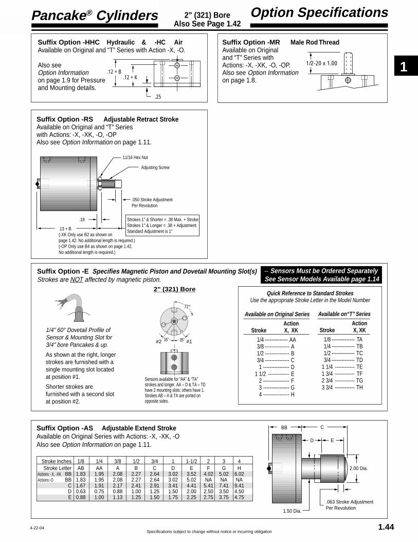
1
Specifications subject to change without notice or incurring obligation
Pancake® Cylinders
1.44
Option Specifications2" (321) BoreAlso See Page 1.42
72°
35°35° #1#2
Sensors available for “AA” & “TA” strokes and longer. AA – D & TA – TD have 2 mounting slots; others have 1. Strokes AB – A & TA are ported on opposite sides.
2" (321) BoreQuick Reference to Standard Strokes
Use the appropriate Stroke Letter in the Model Number
1/4" 60° Dovetail Profile ofSensor & Mounting Slot for3/4" bore Pancakes & up.
As shown at the right, longerstrokes are furnished with asingle mounting slot locatedat position #1.
Shorter strokes arefurnished with a second slotat position #2.
Available on Original Series
ActionStroke X, XK
1/4 -------------- AA3/8 --------------- A1/2 --------------- B3/4 --------------- C1 ---------------- D
1 1/2 ------------- E2 ---------------- F3 ---------------- G4 ---------------- H
Available on“T” Series
ActionStroke X, XK
1/8 -------------- TA1/4 -------------- TB1/2 -------------- TC3/4 -------------- TD
1 1/4 ------------ TE1 3/4 ------------ TF2 3/4 ------------ TG3 3/4 ------------ TH
Suffix Option -E Specifies Magnetic Piston and Dovetail Mounting Slot(s)Strokes are NOT affected by magnetic piston.
– Sensors Must be Ordered SeparatelySee Sensor Models Available page 1.14
4-22-04
Suffix Option -AS Adjustable Extend StrokeAvailable on Original Series with Actions: -X, -XK, -OAlso see Option Information on page 1.11.
BB C
ED
2.00 Dia.
1.50 Dia.
.063 Stroke AdjustmentPer Revolution
Stroke Inches 1/8 1/4 3/8 1/2 3/4 1 1-1/2 2 3 4Stroke Letter AB AA A B C D E F G H
Actions: -X, -XK BB 1.83 1.95 2.08 2.27 2.64 3.02 3.52 4.02 5.02 6.02Actions:-O BB 1.83 1.95 2.08 2.27 2.64 3.02 5.02 NA NA NA
C 1.67 1.91 2.17 2.41 2.91 3.41 4.41 5.41 7.41 9.41D 0.63 0.75 0.88 1.00 1.25 1.50 2.00 2.50 3.50 4.50E 0.88 1.00 1.13 1.25 1.50 1.75 2.25 2.75 3.75 4.75
Suffix Option -RS Adjustable Retract StrokeAvailable on Original and “T” Serieswith Actions: -X, -XK, -O, -OPAlso see Option Information on page 1.11.
Suffix Option -HHC Hydraulic & -HC AirAvailable on Original and “T” Series with Action -X, -O.
Also seeOption Informationon page 1.9 for Pressureand Mounting details.
Suffix Option -MR Male Rod ThreadAvailable on Originaland “T” Series withActions: -X, -XK, -O, -OP.Also see Option Informationon page 1.8.
.19
.13 + B(-XK Only use B2 as shown on page 1.42. No additional length is required.)(-OP Only use B4 as shown on page 1.42. No additional length is required.)
11/16 Hex Nut
.050 Stroke AdjustmentPer Revolution
Adjusting Screw
Strokes 1" & Shorter = .38 Max. + StrokeStrokes 1" & Longer = .38 + AdjustmentStandard Adjustment is 1"
1/2-20 x 1.00.12 + B
.12 + K
.25

1
Pancake® Cylinders
Specifications subject to change without notice or incurring obligation1.45
2" (321) BoreDouble Rod
Standard Specifications
4-22-04
Action –XDR Original SeriesDouble Rod, Double Acting
Action –XDRK Original SeriesDouble Rod, Double Acting, Nonrotating
Action –ODR Original SeriesDouble Rod, Single Acting, Spring Retracted
1/2-20 x EFemale Rod Thread
2.81 Bolt Circle .27 Dia. Thru.38 C'Bore x .26 Dp.for 2, 1/4" SHCS
3.245/8 x .11Wrench Flat
.75 Rod Dia.72°.14
B K
1/8 NPTStrokes AB–A are Ported on Opposite Sides
Rod End Face
YZ
Cap End Face
.75
.14 + Stroke
1/2-20 x EFemale Rod Thread
2.81 Bolt Circle .27 Dia. Thru.38 C'Bore x .26 Dp.for 2, 1/4" SHCS
3.245/8 x .11Wrench FlatRandomRotation
.75 Rod Dia.72°.14
B K
1/8 NPTStrokes AB–A are Ported on Opposite Sides
Rod End Face
YZ
Cap End Face
.75
.14 + Stroke
RodRotationTolerance± 1°
1/2-20 x EFemale Rod Thread2.81 Bolt Circle .27 Dia. Thru.38 C'Bore x .26 Dp.for 2, 1/4" SHCS
3.245/8 x .11Wrench Flat
.75 Rod Dia.72°
.14
B K
1/8 NPT
Rod End Face
YZ
Cap End Face
.75
.14 + Stroke
Rod End VentStroke E
.71 Rod End VentStrokes AB – D
Stroke, Inches 1/8 1/4 3/8 1/2 3/4 1 1-1/2 2 3 4Stroke, Letter AB AA A B C D E F G H
B 1.83 1.95 2.08 2.27 2.64 3.02 3.52 4.02 5.02 6.02E .40 .50 .63 .63 .75 .88 .88 .88 .88 .88K 1.44 1.56 1.69 1.89 2.25 2.63 3.13 3.63 4.63 5.63Y .52 .52 .52 .52 .52 .52 .52 .52 .52 .52Z .70 .83 .95 1.14 1.52 1.89 2.39 2.89 3.89 4.89
Weight, lb. 1.56 1.64 1.72 1.86 2.15 2.44 2.80 3.18 3.94 4.72
Stroke, Inches 1/8 1/4 3/8 1/2 3/4 1 1-1/2 2 3 4Stroke, Letter AB AA A B C D E F G H
B 1.83 1.95 2.08 2.27 2.64 3.02 3.52 4.02 5.02 6.02E .40 .50 .63 .63 .75 .88 .88 .88 .88 .88K 1.44 1.56 1.69 1.89 2.25 2.63 3.13 3.63 4.63 5.63Y .52 .52 .52 .52 .52 .52 .52 .52 .52 .52Z .70 .83 .95 1.14 1.52 1.89 2.39 2.89 3.89 4.89
Weight, lb. 1.70 1.78 1.87 2.01 2.31 2.61 2.98 3.37 4.16 4.97
See page 1.16 forMounting BoltsForce Area = 2.70Seal Kit = 321-SK
See page 1.16 forMounting BoltsForce Area = 2.51Seal Kit = 321-SK-K
See page 1.16 forMounting BoltsForce Area = 2.70Seal Kit = 321-SK
Rod End Face Vent
Stroke, Inches 1/8 1/4 3/8 1/2 3/4 1 1-1/2Stroke, Letter AB AA A B C D E
B 1.83 1.95 2.08 2.27 2.64 3.02 5.02E .40 .50 .63 .63 .75 .88 .88K 1.44 1.56 1.69 1.89 2.25 2.63 4.63Y .52Z .70 .83 .95 1.14 1.52 1.89 3.89
Weight, lb. 1.51 1.60 1.69 1.81 2.10 2.39 4.16Spring Return Forces, lb.Preload 12.0 6.2 12.0 7.0 5.0 4.7 5.0End of Stroke 18.0 18.0 21.0 20.0 15.5 20.0 20.0

1
Specifications subject to change without notice or incurring obligation
Pancake® Cylinders
1.46
Option Specifications2" (321) BoreAlso See Page 1.45
2" (321) Bore
Quick Reference to Standard StrokesUse the appropriate Stroke Letter in the Model Number
1/4" 60° Dovetail Profile ofSensor & Mounting Slot for3/4" bore Pancakes & up.
As shown at the right, longerstrokes are furnished with asingle mounting slot located atposition #1.
Shorter strokes are furnishedwith a second slot at position #2.
72°
35°35° #1#2
Sensors available for “AA”strokes and longer. AA – D have 2 mounting slots; others have 1. Strokes AB – Aare ported on opposite sides.
Suffix Option -E Specifies Magnetic Piston and Dovetail Mounting Slot(s)Strokes are NOT affected by magnetic piston.
Available on Original Series
ActionStroke XDR, XDRK
1/4 -------------- AA3/8 --------------- A1/2 --------------- B3/4 --------------- C1 ---------------- D
1 1/2 ------------- E2 ---------------- F3 ---------------- G4 ---------------- H
– Sensors Must be Ordered SeparatelySee Sensor Models Available page 1.14
4-22-04
Suffix Options -MR, -MR1, -MR2 Male Rod Thread
Available on Original Series with Actions -XDR, -XDRK, -ODR.
For Rod End only use –MRFor Cap End only use –MR1For Both Ends –MR2
Also see Option Information on Page 1.8
1/2-20 x 1.00
The Suffix Options charted on the right are available onOriginal Series with the Actions indicated (✓ ). They require nodimensional changes from the Standard Specifications on page1.45. – Also see Option Information on pages 1.7 thru 1.15.
T V Q H N C1–C7 LF LR LFR BF BR BFR P14 16 31-XDR ✓ ✓ ✓ ✓ ✓ ✓ ✓ ✓ ✓ ✓ ✓ ✓ ✓ ✓ ✓
-XDRK NA ✓ ✓ NA ✓ ✓ NA ✓ NA ✓ ✓ ✓ ✓ ✓ ✓-ODR NA ✓ ✓ ✓ ✓ NA NA ✓ NA NA ✓ NA ✓ ✓ ✓
Prefix Option -M Metric Cylinder & Rod Thread, 50.8mm BoreAvailable on Original Series with Actions: -XDR, -XDRK, -ODRAlso see Option Information on page 1.7.
71.4mm Bolt Circle
G1/8 Ports with 14mm Spotface
M12 x 25.4
Standard Female Rod Thread M12.Male Rod ThreadOption -MR shown.
Mounting Holes6.7mm Diameter Thru10.3mm C'Bore x 6.4mm Dp.2 Places for M6 SHCS
Thread PitchesM6 = 1.0mmM12 = 1.75mm
Conversion FactorInches x 25.4 = mm
Stroke mm 3.2 6.4 9.5 12.7 19.1 25.4 38.1 50.8 76.2 101.6
Stroke Letter AB AA A B C D E F G H

1
Pancake® Cylinders
Specifications subject to change without notice or incurring obligation
ModelNumberCode
Suffix OptionsBorePrefix Options Stroke Action
–C –521 –X MRLeave blank ifnone desired
Metric MSee pages 1.7, 1.49 & 1.52
Bore Code2 1/2" 521
63.5mm 521
Model Number2 1/2" (521) Bore
1.47
A complete library of cylinder CAD drawings is available from your local Fabco-Air Distributoror from the Fabco-Air web site – http://www.fabco-air.com
6-3-02
HOW TO ORDER1. Under Stroke – select letter(s) for desired Series
and Stroke.
2. Under Bore – select 521 for 2 1/2" bore.Seven Other Bore Sizes are AvailableBore Bore Code See page1/2" -------------- 5 ----------------- 1.173/4" -------------- 7 ----------------- 1.231 1/8" ---------- 121 --------------- 1.291 5/8" ---------- 221 --------------- 1.352" -------------- 321 --------------- 1.413" -------------- 721 --------------- 1.534" ------------- 1221 -------------- 1.59
3. Under Action – select letter(s) for desired action.
4. Under Prefix & Suffix Options–select letter(s) for desired optionsand add to model number.
EXAMPLESA-521-X
Original Series, 1/2" stroke - 2 1/2" Bore -Single Rod, Double Acting
TC-521-X-MR“T” Series, 3/4" Stroke - 2 1/2" Bore -Single Rod, Double Acting - Male Rod Thread
ActionSingle rod
Double acting -XDouble acting, NonrotatingInternal guide pins - 150 psi max -XKSingle acting, spring retracted -OSingle acting, spring extended -OP
Double rodDouble acting -XDRDouble acting, NonrotatingInternal guide pins - 150 psi max -XDRKSingle acting, spring retracted -ODR
See pages 1.5 & 1.6 for Action Information.See pages 1.48 & 1.51 for Standard Specifications
Grey shadingindicates sensorsare not available.
Strokes are NOTaffected by magneticpiston Option “E”
Standard Strokes
Original Series
XAction XK
XDR OXDRK ODR OP
Stroke1/8 AB AB AB1/4 AA AA AA1/2 A A A3/4 B B B1 C C C
1 1/2 D D –2 E – –3 F – –4 G – –
“T” SeriesIncludes PTFEpiston bearing
XAction XK O OPStroke
1/4 TA TA TA1/2 TB TB TB3/4 TC TC TC
1 1/4 TD TD –1 3/4 TE – –2 3/4 TF – –3 3/4 TG – –
See pages 1.3 – 1.15 for general option informationand pages 1.49, 1.50 & 1.52 for option specifications
of 2 1/2" bore models.
Suffix Options
Male rod thread: Single rod -MRDouble rod, rod end -MRDouble rod, cap end -MR1Double rod, both ends -MR2
PTFE seals -TViton seals -VQuad seals -QExternal guide, nonrotating
for load guiding (See page 1.65) -GHydraulic:
Standard cover -HThick cover -HHC
Air service:Thick cover -HC
1/4 NPT ports -P14Hole thru double rod shaft: 5/32" hole -16
Plus size: 1/4" hole -25150 psi max
Finish: ProCoat™ (Electroless Nickel) -NStroke collar: 1/8" -C1
1/4" -C2 3/8" -C31/2" -C4 5/8" -C53/4" -C6 7/8" -C7
Sound limiters: Rod end -LFCap end -LRBoth ends -LFR
Rubber Bumpers: Rod end -BFCap end -BRBoth ends -BFR
Adjustable extend stroke -AS(Full stroke adjustment is standard)Adjustable retract stroke (Over 1"adjustment add desired length, e.g. -RS2) -RSClevis mount: Ports in-line with slot -PM
Ports 90° to slot -SMMagnetic piston & sensor mounting slot(s) -EOrder sensors separately. See page 1.14.Stroke length determines numberof mounting slots. See page 1.14, 1.50, 1.52

1
Specifications subject to change without notice or incurring obligation
Pancake® Cylinders
1.48
Standard Specifications2-1/2" (521) BoreSingle Rod
4-22-04
1/2-20 x E1Female Rod Thread
3.25 Bolt Circle .27 Dia. Thru.38 C'Bore x .26 Dp.for 4, 1/4" SHCSequally spaced
3.745/8 x .11Wrench Flat
.75 Rod Dia.45°
.14
B1 K1
1/8 NPTStrokes AB & AA are Ported on Opposite Sides
Rod End Face
Y1Z1
Cap End Face
.19
1/2-20 x E2Female Rod Thread
3.25 Bolt Circle .27 Dia. Thru.38 C'Bore x .26 Dp.for 4, 1/4" SHCSequally spaced
3.745/8 x .11Wrench FlatRandomRotation
.75 Rod Dia.45°
.14
B2 K2
1/8 NPTStrokes AB & AA are Ported on Opposite Sides
Rod End Face
Y2Z2
Cap End Face
.38
RodRotationTolerance± 1°
1/2-20 x E3Female Rod Thread
3.25 Bolt Circle .27 Dia. Thru.38 C'Bore x .26 Dp.for 4, 1/4" SHCSequally spaced
3.745/8 x .11Wrench Flat
.75 Rod Dia.
45°.14
B3 K3
1/8 NPT
Rod End Face
Y3Z3
Cap End Face
.19
.71 Rod End VentStrokes AB-C & TA - TCRod End VentStrokes D & TD
1/2-20 x E4Female Rod Thread
3.25 Bolt Circle .27 Dia. Thru.38 C'Bore x .26 Dp.for 4, 1/4" SHCSequally spaced
3.745/8 x .11Wrench Flat
.75 Rod Dia.
45°
.14 + Stroke
B4 K4
1/8 NPTStrokes AB & AA are Ported on Opposite Sides
Rod End Face
Y4Z4
Cap End Face
.63
Action –XDouble Acting
Action –XKDouble ActingNonrotating
See page 1.16 forMounting Bolts.Push area = 4.71Pull area = 4.27Seal Kits for Series:Original = 521-SK-K"T" = 521-SKG-K
See page 1.16 forMounting Bolts.Push area = 4.91Pull area = 4.47Seal Kits for Series:Original = 521-SK"T" = 521-SKG
Action –OPSingle ActingSpring Extended
See page 1.16 forMounting Bolts.Pull area = 4.47See Chart for SpringForces: Preload& End of StrokeSeal Kits for Series:Original = 521-SK"T" = 521-SKG
Action –OSingle ActingSpring Retracted
See page 1.16 forMounting Bolts.Push area = 4.91See Chart for SpringForces: Preload& End of StrokeSeal Kits for Series:Original = 521-SK"T" = 521-SKG
Action –X Double Acting
Original Series "T" Series
Action –OP Single Acting, Spring Extended
Action –O Single Acting, Spring Retracted
Action –XK Double Acting, Nonrotating
Action –X Double Acting
Rod End Face VentRod End Face Vent
Stroke, Inches 1/8 1/4 1/2 3/4 1 1 1/2 2 3 4 1/4 1/2 3/4 1 1/4 1 3/4 2 3/4 3 3/4Stroke, Letter AB AA A B C D E F G TA TB TC TD TE TF TG
B1 1.45 1.58 1.83 2.20 2.33 2.83 3.33 4.33 5.33 1.83 2.20 2.33 2.83 3.33 4.33 5.33E1 .56 .63 .63 .88 .88 .88 .88 .88 .88 .63 .88 .88 .88 .88 .88 .88K1 1.05 1.18 1.43 1.80 1.93 2.43 2.93 3.93 4.93 1.43 1.80 1.93 2.43 2.93 3.93 4.93Y1 .52 .52 .52 .64 .64 .64 .64 .64 .64 .52 .64 .64 .64 .64 .64 .64Z1 .89 1.02 1.27 1.64 1.77 2.27 2.77 3.77 4.77 1.27 1.64 1.77 2.27 2.77 3.77 4.77
Weight, lb. 1.43 1.50 1.67 2.00 2.03 2.38 2.73 3.46 4.19 1.89 2.22 2.25 2.60 2.95 3.68 4.41
B2 1.64 1.77 2.02 2.39 2.52 3.02 3.52 4.52 5.52 2.02 2.39 2.52 3.02 3.52 4.52 5.52E2 .56 .63 .63 .88 .88 .88 .88 .88 .88 .63 .88 .88 .88 .88 .88 .88K2 1.24 1.37 1.62 1.99 2.12 2.62 3.12 4.12 5.12 1.62 1.99 2.12 2.62 3.12 4.12 5.12Y2 .52 .52 .52 .64 .64 .64 .64 .64 .64 .52 .64 .64 .64 .64 .64 .64Z2 .89 1.02 1.27 1.64 1.77 2.27 2.77 3.77 4.77 1.27 1.64 1.77 2.27 2.77 3.77 4.77
Weight, lb. 1.64 1.72 1.89 2.23 2.27 2.63 3.00 3.75 4.51 2.11 2.45 2.50 2.85 3.22 4.00 4.73
B3 1.45 1.58 1.83 2.20 2.33 4.33 NA* NA* NA* 1.83 2.20 2.33 4.33 NA* NA* NA*E3 .56 .63 .63 .88 .88 .88 NA* NA* NA* .63 .88 .88 .88 NA* NA* NA*K3 1.05 1.13 1.43 1.80 1.93 3.93 NA* NA* NA* 1.43 1.80 1.93 3.93 NA* NA* NA*Y3 .64 NA* NA* NA* .64 NA* NA* NA*Z3 .89 1.02 1.27 1.64 1.77 3.77 NA* NA* NA* 1.27 1.64 1.77 3.77 NA* NA* NA*
Weight,. lb. 1.38 1.46 1.62 1.94 1.96 3.60 NA* NA* NA* 1.84 2.16 2.18 3.82 NA* NA* NA*Preload, lb. 12.0 6.2 7.0 5.0 4.7 7.3 NA* NA* NA* 13.1 10.6 8.0 9.5 NA* NA* NA*End of Stroke, lb. 18.0 18.0 20.0 15.5 20.0 20.0 NA* NA* NA* 20.0 15.5 20.0 20.0 NA* NA* NA*
B4 2.02 2.27 2.77 3.39 3.77 NA* NA* NA* NA* 2.52 3.14 3.52 NA* NA* NA* NA*E4 .56 .63 .63 .88 .88 NA* NA* NA* NA* .63 .88 .88 NA* NA* NA* NA*K4 1.49 1.62 1.87 2.24 2.37 NA* NA* NA* NA* 1.87 2.24 2.37 NA* NA* NA* NA*Y4 .65 .77 1.02 1.40 1.64 NA* NA* NA* NA* .77 1.14 1.39 NA* NA* NA* NA*Z4 1.02 1.27 1.77 2.39 2.77 NA* NA* NA* NA* 1.52 2.14 2.52 NA* NA* NA* NA*
Weight, lb. 1.91 1.98 2.16 2.49 2.51 NA* NA* NA* NA* 2.38 2.71 2.73 NA* NA* NA* NA*Preload, lb. 6.2 2.5 5.5 5.0 5.2 NA* NA* NA* NA* 11.2 12.4 10.2 NA* NA* NA* NA*End of Stroke, lb. 12.0 12.0 18.5 15.5 20.5 NA* NA* NA* NA* 18.5 21.1 22.6 NA* NA* NA* NA*
Action –XK Double Acting, Nonrotating
NA* = Not Available
Action –O Single Acting, Spring Retracted
Action –OP Single Acting, Spring Extended

1
Pancake® Cylinders
Specifications subject to change without notice or incurring obligation1.49
Option Specifications2-1/2" (521) BoreAlso See Page 1.48
12-15-04
Prefix Option -M Metric Cylinder & Rod Thread 63.5mm BoreAvailable on Original and “T” Series with Actions: -X, -XK, -O, -OPAlso see Option Information on page 1.7.
82.5mm Bolt Circle
G1/8 Ports with 14mm Spotface
M12 x 25.4
Standard Female Rod Thread M12.Male Rod ThreadOption -MR shown.
Mounting Holes6.7mm Diameter Thru10.3mm C'Bore x 6.4mm Dp.4 Places for M6 SHCS
Thread PitchesM6 = 1.0mmM12 = 1.75mm
Conversion FactorInches x 25.4 = mm
The Suffix Options charted on the right are available on Originaland “T” Series with the Actions indicated (✓ ). They require nodimensional changes from the Standard Specifications on page1.48. – Also see Option Information on pages 1.7 thru 1.15.
T V Q H N C1–C7 LF LR LFR BF BR BFR P14-X ✓ ✓ ✓ ✓ ✓ ✓ ✓ ✓ ✓ ✓ ✓ ✓ ✓
-XK NA ✓ ✓ ✓ ✓ ✓ NA ✓ NA ✓ ✓ ✓ ✓-O NA ✓ ✓ ✓ ✓ NA NA ✓ NA NA ✓ NA ✓
-OP NA ✓ ✓ ✓ ✓ ✓ ✓ ✓ ✓ ✓ NA NA ✓
Suffix Options -PM & -SM Clevis MountAvailable On Original and “T” Serieswith Actions: -X, -XK, -O, -OPAlso see Option Information on page 1.13.
EM-521 Eye Bracket KitMates with Clevis Mount shown above.Order separately.
EM-121 Eye Bracket KitMates with any Rod Clevis shown above.Order separately.
.50
.97
1.63
Oil filled bushings
Chart
.90
.50 1.86
-PMPort LocationIN LINE with Slot -SM
Port Location90° to Slot
Also see page 1.48
Note 1
ChartAction Dimension-X, -O, -OP 1.19 + B -XK 1.00 + B
Note 1:Hole Diameter = .501Pin Diameter = .500Pin (416 Stainless Steel)and Clips are included.
.751.13
2.25
.38
2.00
2.001.38
Hole .501Oil filled bushingis standard
.47
1.38 1.50.33 Dia. 4 Placesfor Flat Head ScrewsFour 5/16-18 x 1"FHSCS are included
Material: Zinc Die Casting
.44.69
1.38
.25
1.50
1.501.13
Hole .3135Oil filled bushingis standard
.30
1.13 .94.27 Dia. 4 Placesfor Flat Head ScrewsFour 1/4-20 x 3/4"FH(#12)M Screwsare included
Material: Zinc Die Casting
RC-Chart Rod Clevis and PinThreaded Stud mates with Female Rod threadin the Pancake® Cylinders.Slot and Pin Mate with EM-121 Eye Bracketshown below.
.32
Pin Diameter .3125
1.691.31
1.21 .63 . 61
1.00
Materials:Clevis – Steel, Black OxideStud – SteelPin – 416 Stainless SteelPin & Clips are included
Rod Clevis NumberRC-54RC-56
MRC-54MRC-56
Strokes
ABAA–GMAB
MAA–MG
Thread Length
.39"
.62"9.9mm15.7mm
CHART1/2-20 x Thread Length
Metric M12 x Thread Length
Stroke mm 3.2 6.4 12.7 19.1 25.4 38.1 50.8 76.2 101.6
Stroke Letter AB AA A B C D E F G
Stroke mm 6.4 12.7 19.1 31.8 44.5 69.9 95.3Stroke Letter TA TB TC TD TE TF TG
Original Series
“T” Series

1
Specifications subject to change without notice or incurring obligation
Pancake® Cylinders
1.50
Option Specifications2-1/2" (521) BoreAlso See Page 1.48
Suffix Option -RS Adjustable Retract StrokeAvailable on Original and “T” Serieswith Actions: -X, -XK, -O, -OPAlso see Option Information on page 1.11.
Suffix Option -HHC Hydraulic & -HC AirAvailable on Original and “T” Series with Action -X, -O.
Also seeOption Informationon page 1.9 for Pressureand Mounting details.
Suffix Option -MR Male Rod ThreadAvailable on Originaland “T” Series withActions: -X, -XK, -O, -OP.Also see Option Informationon page 1.8.
.19
.19 + B(-XK only use B2 as shown on page 1.48. No additional length is required.)(-OP Only use B4 as shown on page 1.48.No additional length is required.)
11/16 Hex Nut
.050 Stroke AdjustmentPer Revolution
Adjusting Screw
Strokes 1" & Shorter = .50 Max. + StrokeStrokes 1" & Longer = .38 + AdjustmentStandard Adjustment is 1"
1/2-20 x 1.00.19 + B.19 + K
.38
4-22-04
45°
90°90°
#1#2
Sensors available for “AA” & “TA” strokes and longer. AA – C & TA – TC have 2 mounting slots; others have 1. Strokes AB & AA are ported on opposite sides.
2 1/2" (521) Bore
Quick Reference to Standard StrokesUse the appropriate Stroke Letter in the Model Number
1/4" 60° Dovetail Profile ofSensor & Mounting Slot for3/4" bore Pancakes & up.
As shown at the right, longerstrokes are furnished with asingle mounting slot locatedat position #1.
Shorter strokes arefurnished with a second slotat position #2.
Available on Original SeriesAction
Stroke X, XK
1/4 ---------------- AA1/2 ----------------- A3/4 ----------------- B1 ------------------- C1 1/2 -------------- D2 ------------------- E3 ------------------- F4 ------------------- G
Available on“T” SeriesAction
Stroke X, XK
1/4 --------------- TA1/2 --------------- TB3/4 --------------- TC1 1/4 ------------- TD1 3/4 ------------- TE2 3/4 ------------- TF3 3/4 ------------- TG
Suffix Option -E Specifies Magnetic Piston and Dovetail Mounting Slot(s)Strokes are NOT affected by magnetic piston.
– Sensors Must be Ordered SeparatelySee Sensor Models Available page 1.14
Suffix Option -AS Adjustable Extend StrokeAvailable on Original Series with Actions: -X, -XK, -OAlso see Option Information on page 1.11.
BB C
ED
2.00 Dia.
1.50 Dia.
.063 Stroke AdjustmentPer Revolution
Stroke Inches 1/8 1/4 1/2 3/4 1 1-1/2 2 3 4Stroke Letter AB AA A B C D E F G
Actions: -X, -XK BB 2.02 2.14 2.39 2.77 2.89 3.39 3.89 4.89 5.89Actions:-O BB 2.02 2.14 2.39 2.77 2.89 4.89 NA NA NA
C 1.67 1.91 2.41 2.91 3.41 4.41 5.41 7.41 9.41D 0.63 0.75 1.00 1.25 1.50 2.00 2.50 3.50 4.50E 0.88 1.00 1.25 1.50 1.75 2.25 2.75 3.75 4.75

1
Pancake® Cylinders
Specifications subject to change without notice or incurring obligation1.51 4-22-04
Standard Specifications2-1/2" (521) BoreDouble Rod
Action –XDR Original SeriesDouble Rod, Double Acting
Stroke, Inches 1/8 1/4 1/2 3/4 1 1-1/2 2 3 4Stroke, Letter AB AA A B C D E F G
B 2.02 2.14 2.39 2.77 2.89 3.39 3.89 4.89 5.89E .56 .63 .63 .88 .88 .88 .88 .88 .88K 1.63 1.75 2.00 2.38 2.50 3.00 3.50 4.50 5.50Y .52 .52 .52 .64 .64 .64 .64 .64 .64Z .89 1.02 1.27 1.64 1.77 2.27 2.77 3.77 4.77
Weight, lb. 2.20 2.29 2.48 2.82 2.83 3.28 3.67 4.60 5.40
Action –XDRK Original SeriesDouble Rod, Double Acting, Nonrotating
Action –ODR Original SeriesDouble Rod, Single Acting, Spring Retracted
Stroke, Inches 1/8 1/4 1/2 3/4 1 1-1/2 2 3 4Stroke, Letter AB AA A B C D E F G
B 2.02 2.14 2.39 2.77 2.89 3.39 3.89 4.89 5.89E .56 .63 .63 .88 .88 .88 .88 .88 .88K 1.63 1.75 2.00 2.38 2.50 3.00 3.50 4.50 5.50Y .52 .52 .52 .64 .64 .64 .64 .64 .64Z .89 1.02 1.27 1.64 1.77 2.27 2.77 3.77 4.77
Weight, lb. 2.34 2.43 2.63 2.97 2.99 3.45 3.85 4.79 5.62
1/2-20 x EFemale Rod Thread
3.25 Bolt Circle .27 Dia. Thru.38 C'Bore x .26 Dp.for 4, 1/4" SHCSequally spaced
3.745/8 x .11Wrench Flat
.75 Rod Dia.45°
.14
B K
1/8 NPT
Rod End Face
YZ
Cap End Face
.75
.14 + Stroke
.71 Rod End VentStrokes AB – C
Rod End VentStroke D
1/2-20 x EFemale Rod Thread
3.25 Bolt Circle .27 Dia. Thru.38 C'Bore x .26 Dp.for 4, 1/4" SHCSequally spaced
3.745/8 x .11Wrench Flat
.75 Rod Dia.45°
.14
B K
1/8 NPTStrokes AB & AA are Ported on Opposite Sides
Rod End Face
YZ
Cap End Face
.75
.14 + Stroke
1/2-20 x EFemale Rod Thread
3.25 Bolt Circle .27 Dia. Thru.38 C'Bore x .26 Dp.for 4, 1/4" SHCSequally spaced
3.745/8 x .11Wrench FlatRandomRotation
.75 Rod Dia.45°
.14
B K
1/8 NPTStrokes AB & AA are Ported on Opposite Sides
Rod End Face
YZ
Cap End Face
.75
.14 + Stroke
RodRotationTolerance± 1°
Rod End Face Vent
Stroke, Inches 1/8 1/4 1/2 3/4 1 1-1/2Stroke, Letter AB AA A B C D
B 2.02 2.14 2.39 2.77 2.89 4.89E .56 .63 .63 .88 .88 .88K 1.63 1.75 2.00 2.38 2.50 4.50Y .64Z .89 1.02 1.27 1.64 1.77 3.77
Weight, lb. 2.14 2.23 2.41 2.76 2.77 4.52Spring Return Forces, lb.Preload 12.0 6.3 7.0 5.0 4.8 7.3End of Stroke 18.0 18.0 20.0 15.5 20.0 20.0
See page 1.16 forMounting BoltsForce Area = 4.47Seal Kit = 521-SK
See page 1.16 forMounting BoltsForce Area = 4.27Seal Kit = 521-SK-K
See page 1.16 forMounting BoltsForce Area = 4.47Seal Kit = 521-SK

1
Specifications subject to change without notice or incurring obligation
Pancake® Cylinders
1.52
Option Specifications2-1/2" (521) BoreAlso See Page 1.51
4-22-04
The Suffix Options charted on the right are available onOriginal Series with the Actions indicated (✓ ). They require nodimensional changes from the Standard Specifications on page1.51. – Also see Option Information on pages 1.7 thru 1.15.
T V Q H N C1–C7 LF LR LFR BF BR BFR P14 16 25-XDR ✓ ✓ ✓ ✓ ✓ ✓ ✓ ✓ ✓ ✓ ✓ ✓ ✓ ✓ ✓
-XDRK NA ✓ ✓ ✓ ✓ ✓ NA ✓ NA ✓ ✓ ✓ ✓ ✓ ✓-ODR NA ✓ ✓ ✓ ✓ NA NA ✓ NA NA ✓ NA ✓ ✓ ✓
Prefix Option -M Metric Cylinder & Rod Thread, 63.5mm BoreAvailable on Original Series with Actions: -XDR, -XDRK, -ODRAlso see Option Information on page 1.7.
82.5mm Bolt Circle
G1/8 Ports with 14mm Spotface
M12 x 25.4
Standard Female Rod Thread M12.Male Rod ThreadOption -MR shown.
Mounting Holes6.7mm Diameter Thru10.3mm C'Bore x 6.4mm Dp.4 Places for M6 SHCS
Thread PitchesM6 = 1.0mmM12 = 1.75mm
Conversion FactorInches x 25.4 = mm
Stroke mm 3.2 6.4 12.7 19.1 25.4 38.1 50.8 76.2 101.6
Stroke Letter AB AA A B C D E F G
Suffix Options -MR, -MR1, -MR2 Male Rod Thread
Available on Original Series with Actions -XDR, -XDRK, -ODR.
For Rod End only use –MRFor Cap End only use –MR1For Both Ends use –MR2
Also see Option Information on Page 1.8.
1/2-20 x 1.00
2 1/2" (521) Bore
Quick Reference to Standard StrokesUse the appropriate Stroke Letter in the Model Number
1/4" 60° Dovetail Profile ofSensor & Mounting Slot for3/4" bore Pancakes & up.
As shown at the right, longerstrokes are furnished with asingle mounting slot locatedat position #1.
Shorter strokes arefurnished with a second slotat position #2.
45°
90°90°
#1#2
Sensors available for “AA”strokes and longer. AA – C have 2 mounting slots; others have 1. Strokes AB & AA are ported on opposite sides.
Suffix Option -E Specifies Magnetic Piston and Dovetail Mounting Slot(s)Strokes are NOT affected by magnetic piston.
Available on Original Series
ActionStroke XDR, XDRK
1/4 ---------------- AA1/2 ----------------- A3/4 ----------------- B1 ------------------- C1 1/2 -------------- D2 ------------------- E3 ------------------- F4 ------------------- G
– Sensors Must be Ordered SeparatelySee Sensor Models Available page 1.14

1
Pancake® Cylinders
Specifications subject to change without notice or incurring obligation
ModelNumberCode
Suffix OptionsPrefix Options Stroke Action
–C –721 – MRLeave blank ifnone desired
Bore Code3" 721
76.2mm 721
Metric MSee pages 1.7, 1.55 & 1.58
X
Model Number3" (721) Bore
HOW TO ORDER1. Under Stroke – select letter(s) for desired Series
and Stroke.2. Under Bore – select 721 for 3" bore.
Seven Other Bore Sizes are AvailableBore Bore Code See page1/2" -------------- 5 ----------------- 1.173/4" -------------- 7 ----------------- 1.231 1/8" ---------- 121 --------------- 1.291 5/8" ---------- 221 --------------- 1.352" -------------- 321 --------------- 1.412 1/2" ---------- 521 --------------- 1.474" ------------- 1221 -------------- 1.59
3. Under Action – select letter(s) for desired action.
4. Under Prefix & Suffix Options–select letter(s) for desired optionsand add to model number.
EXAMPLESA-721-X
Original Series, 1/2" stroke - 3" Bore -Single Rod, Double Acting
TC-721-X-MR“T” Series, 3/4" Stroke - 3" Bore -Single Rod, Double Acting - Male Rod Thread
1.53
A complete library of cylinder CAD drawings is available from your local Fabco-Air Distributoror from the Fabco-Air web site – http://www.fabco-air.com
6-3-02
ActionSingle rod
Double acting -XDouble acting, NonrotatingInternal guide pins - 150 psi max -XKSingle acting, spring retracted -OSingle acting, spring extended -OP
Double rodDouble acting -XDRDouble acting, NonrotatingInternal guide pins - 150 psi max -XDRKSingle acting, spring retracted -ODR
See pages 1.5 & 1.6 for Action Information.See pages 1.54 & 1.57 for Standard Specifications
Grey shadingindicates sensorsare not available.
Strokes are NOTaffected by magneticpiston Option “E”
Standard Strokes
Original SeriesX
Action XKXDR O
XDRK ODR OPStroke
1/8 AB AB AB1/4 AA AA AA1/2 A A A3/4 B B B1 C C C
1 1/2 D D –2 E – –3 F – –4 G – –
“T” SeriesIncludes PTFEpiston bearing
XAction XK O OPStroke
1/4 TA TA TA1/2 TB TB TB3/4 TC TC TC
1 1/4 TD TD –1 3/4 TE – –2 3/4 TF – –3 3/4 TG – –
See pages 1.3 – 1.15 for general optioninformation and pages 1.55 , 1.56 & 1.58 for
option specifications of 3" bore models.
Suffix Options
Male rod thread: Single rod -MRDouble rod, rod end -MRDouble rod, cap end -MR1Double rod, both ends -MR2
PTFE seals -TViton seals -VQuad seals -QExternal guide, nonrotating -G
for load guiding (See page 1.65)Hydraulic:
Standard cover -HThick cover -HHC
Air service:Thick cover -HC
1/4 NPT ports -P14Hole thru double rod shaft: 5/32" hole -16
Plus size: 1/4" hole -25150 psi max
Finish: ProCoat™ (Electroless Nickel) -N
Stroke collar: 1/8" -C11/4" -C2 3/8" -C31/2" -C4 5/8" -C53/4" -C6 7/8" -C7
Sound limiters: Rod end -LFCap end -LRBoth ends -LFR
Rubber Bumpers: Rod end -BFCap end -BRBoth ends -BFR
Adjustable extend stroke -AS(Full stroke adjustment is standard)Adjustable retract stroke (Over 1"adjustment add desired length, e.g. -RS2) -RSClevis mount: Ports in-line with slot -PM
Ports 90° to slot -SMMagnetic piston & sensor mounting slot(s) -EOrder sensors separately. See page 1.14.Stroke length determines numberof mounting slots. See page 1.14, 1.56, 1.58

1
Specifications subject to change without notice or incurring obligation
Pancake® Cylinders
1.54
Standard Specifications3" (721) BoreSingle Rod
4-22-04
Action –XDouble Acting
Action –XKDouble ActingNonrotating
See page 1.16 forMounting Bolts.Push area = 6.87Pull area = 6.43Seal Kits for Series:Original = 721-SK-K"T" = 721-SKG-K
See page 1.16 forMounting Bolts.Push area = 7.07Pull area = 6.63Seal Kits for Series:Original = 721-SK"T" = 721-SKG
Action –OPSingle ActingSpring Extended
See page 1.16 forMounting Bolts.Pull area = 6.63See Chart for SpringForces: Preload& End of StrokeSeal Kits for Series:Original = 721-SK"T" = 721-SKG
Action –OSingle ActingSpring Retracted
See page 1.16 forMounting Bolts.Push area = 7.07See Chart forSpringForces: Preload& End of StrokeSeal Kits for Series:Original = 721-SK"T" = 721-SKG
Original Series "T" Series
Action –OP Single Acting, Spring Extended
Action –O Single Acting, Spring Retracted
Action –XK Double Acting, Nonrotating
Action –X Double Acting
Rod End Face VentRod End Face Vent
Stroke, Inches 1/8 1/4 1/2 3/4 1 1 1/2 2 3 4 1/4 1/2 3/4 1 1/4 1 3/4 2 3/4 3 3/4Stroke, Letter AB AA A B C D E F G TA TB TC TD TE TF TG
B1 1.52 1.64 1.89 2.14 2.39 2.89 3.39 4.39 5.39 1.89 2.14 2.39 2.89 3.39 4.39 5.39E1 .63 .63 .63 .88 .88 .88 .88 .88 .88 .63 .88 .88 .88 .88 .88 .88K1 1.12 1.24 1.49 1.74 1.99 2.49 2.99 3.99 4.99 1.49 1.74 1.99 2.49 2.99 3.99 4.99Y1 .52 .52 .52 .64 .64 .64 .64 .64 .64 .52 .64 .64 .64 .64 .64 .64Z1 .95 1.08 1.33 1.58 1.83 2.33 2.83 3.83 4.83 1.33 1.58 1.83 2.33 2.83 3.83 4.83
Weight, lb. 1.89 1.97 2.18 2.36 2.57 2.98 3.28 4.22 5.03 2.49 2.68 2.89 3.30 3.70 4.54 5.40
B2 1.71 1.83 2.08 2.33 2.58 3.08 3.58 4.58 5.58 2.08 2.33 2.58 3.08 3.58 4.58 5.58E2 .63 .63 .63 .88 .88 .88 .88 .88 .88 .63 .88 .88 .88 .88 .88 .88K2 1.31 1.43 1.68 1.93 2.18 2.68 3.18 4.18 5.18 1.68 1.93 2.18 2.68 3.18 4.18 5.18Y2 .52 .52 .52 .64 .64 .64 .64 .64 .64 .52 .64 .64 .64 .64 .64 .64Z2 .95 1.08 1.33 1.58 1.83 2.33 2.83 3.83 4.83 1.33 1.58 1.83 2.33 2.83 3.83 4.83
Weight, lb. 2.15 2.24 2.45 2.64 2.86 3.28 3.59 4.56 5.40 2.77 2.96 3.18 3.60 3.91 4.88 5.72
B3 1.52 1.64 1.89 2.14 2.39 4.39 NA* NA* NA* 1.89 2.14 2.39 4.39 NA* NA* NA*E3 .63 .63 .63 .88 .88 .88 NA* NA* NA* .63 .88 .88 .88 NA* NA* NA*K3 1.12 1.24 1.49 1.74 1.99 3.99 NA* NA* NA* 1.49 1.74 1.99 3.99 NA* NA* NA*Y3 .64 NA* NA* NA* .64 NA* NA* NA*Z3 .95 1.08 1.33 1.58 1.83 3.83 NA* NA* NA 1.33 1.58 1.83 3.83 NA* NA* NA*
Weight,. lb. 1.20 1.92 2.11 2.29 2.51 4.36 NA* NA* NA* 2.43 2.61 2.83 4.68 NA* NA* NA*Preload, lb. 12.0 12.0 6.5 5.0 4.7 7.3 NA* NA* NA* 11.7 10.6 7.9 9.5 NA* NA* NA*End of Stroke, lb. 18.0 18.5 15.5 15.5 20.0 20.0 NA* NA* NA* 17.0 19.3 20.0 20.0 NA* NA* NA*
B4 2.08 2.33 2.83 3.33 3.83 NA* NA* NA* NA* 2.58 3.08 3.58 NA* NA* NA* NA*E4 .63 .63 .63 .88 .88 NA* NA* NA* NA* .63 .88 .88 NA* NA* NA* NA*K4 1.55 1.68 1.93 2.18 2.43 NA* NA* NA* NA* 1.93 2.18 2.43 NA* NA* NA* NA*Y4 .65 .77 1.02 1.39 1.64 NA* NA* NA* NA* .77 1.14 1.39 NA* NA* NA* NA*Z4 1.08 1.33 1.83 2.33 2.83 NA* NA* NA* NA* 1.58 2.08 2.58 NA* NA* NA* NA*
Weight, lb. 2.49 2.60 2.69 2.99 3.20 NA* NA* NA* NA* 3.01 3.31 3.52 NA* NA* NA* NA*Preload, lb. 6.2 12.0 6.5 5.0 5.2 NA* NA* NA* NA* 11.7 10.6 8.5 NA* NA* NA* NA*End of Stroke, lb. 12.0 18.5 15.5 15.5 20.5 NA* NA* NA* NA* 17.1 19.3 20.8 NA* NA* NA* NA*
1/2-20 x E4Female Rod Thread
3.81 Bolt Circle .27 Dia. Thru.38 C'Bore x .26 Dp.for 4, 1/4" SHCSequally spaced
4.245/8 x .11Wrench Flat
.75 Rod Dia.45°
.14 + Stroke
B4K4
1/8 NPTStrokes AB & AA are Ported on Opposite Sides
Rod End Face
Y4Z4
Cap End Face
.63
1/2-20 x E3Female Rod Thread
3.81 Bolt Circle .27 Dia. Thru.38 C'Bore x .26 Dp.for 4, 1/4" SHCSequally spaced
4.245/8 x .11Wrench Flat
.75 Rod Dia.
45°
.14
B3 K3
1/8 NPT
Rod End Face
Y3Z3
Cap End Face
.19
.71 Rod End VentStrokes AB-C & TA - TCRod End VentStrokes D & TD
1/2-20 x E1Female Rod Thread3.81 Bolt Circle .27 Dia. Thru.38 C'Bore x .26 Dp.for 4, 1/4" SHCSequally spaced
4.245/8 x .11Wrench Flat
.75 Rod Dia.45°
.14
B1 K1
1/8 NPTStrokes AB & AA are Ported on Opposite Sides
Rod End Face
Y1Z1
Cap End Face
.19
1/2-20 x E2Female Rod Thread3.81 Bolt Circle .27 Dia. Thru.38 C'Bore x .26 Dp.for 4, 1/4" SHCSequally spaced
4.245/8 x .11Wrench FlatRandomRotation
.75 Rod Dia.45°
.14
B2 K2
1/8 NPTStrokes AB & AA are Ported on Opposite Sides
Rod End Face
Y2Z2
Cap End Face
.38
RodRotationTolerance± 1°
NA* = Not Available
Action –OP Single Acting, Spring Extended
Action –O Single Acting, Spring Retracted
Action –XK Double Acting, Nonrotating
Action –X Double Acting

1
Pancake® Cylinders
Specifications subject to change without notice or incurring obligation1.55 12-15-04
Option Specifications3" (721) BoreAlso See Page 1.54
.50
.97
1.63
Oil filled bushings
Chart
.90
.50 1.86
-PMPort LocationIN LINE with Slot -SM
Port Location90° to Slot
Also see page 1.54
Note 1
Note 1:Hole Diameter = .501Pin Diameter = .500Pin (416 Stainless Steel)and Clips are included.
ChartAction Dimension-X, -O, -OP 1.19 + B -XK 1.00 + B
Suffix Options -PM & -SM Clevis MountAvailable on Original and “T” Serieswith Actions: -X, -XK, -O, -OPAlso see Option Information on page 1.13.
EM-521 Eye Bracket KitMates with Clevis Mount shown on the left.Order separately.
RC-56 Rod Clevis and PinThreaded Stud mates with Female Rod threadin the Pancake® Cylinders.Slot and Pin Mate with EM-121 Eye Bracketshown on the right.
EM-121 Eye Bracket KitMates with RC-56 Rod Clevis shown on the left.Order separately.
Prefix Option -M Metric Cylinder & Rod Thread 76.2mm BoreAvailable on Original and “T” Series with Actions: -X, -XK, -O, -OPAlso see Option Information on page 1.7.
The Suffix Options charted on the right are available on Originaland “T” Series with the Actions indicated (✓ ). They require nodimensional changes from the Standard Specifications on page1.54. – Also see Option Information on pages 1.7 thru 1.15.
T V Q H N C1–C7 LF LR LFR BF BR BFR P14-X ✓ ✓ ✓ ✓ ✓ ✓ ✓ ✓ ✓ ✓ ✓ ✓ ✓
-XK NA ✓ ✓ ✓ ✓ ✓ NA ✓ NA ✓ ✓ ✓ ✓-O NA ✓ ✓ ✓ ✓ NA NA ✓ NA NA ✓ NA ✓
-OP NA ✓ ✓ ✓ ✓ ✓ ✓ ✓ ✓ ✓ NA NA ✓
96.8mm Bolt Circle
G1/8 Ports with 14mm Spotface
M12 x 25.4
Standard Female Rod Thread M12. Male Rod ThreadOption -MR shown.
Mounting Holes6.7mm Diameter Thru10.3mm C'Bore x 6.4mm Dp.4 Places for M6 SHCS
Thread PitchesM6 = 1.0mmM12 = 1.75mm
Conversion FactorInches x 25.4 = mm
Stroke mm 3.2 6.4 12.7 19.1 25.4 38.1 50.8 76.2 101.6
Stroke Letter AB AA A B C D E F G
Stroke mm 6.4 12.7 19.1 31.8 44.5 69.9 95.3Stroke Letter TA TB TC TD TE TF TG
Original Series
.751.13
2.25
.38
2.00
2.001.38
Hole .501Oil filled bushingis standard
.47
1.38 1.50.33 Dia. 4 Placesfor Flat Head ScrewsFour 5/16-18 x 1"FHSCS are included
Material: Zinc Die Casting
.44.69
1.38
.25
1.50
1.501.13
Hole .3135Oil filled bushingis standard
.30
1.13 .94.27 Dia. 4 Placesfor Flat Head ScrewsFour 1/4-20 x 3/4"FH(#12)M Screwsare included
Material: Zinc Die Casting
.32
Pin Diameter .3125
1/2-20 x .62Optional Metric#MRC-56M12 x 15.7
1.69
1.31
1.21 .63 . 61
1.00
Materials:Clevis – Steel, Black OxideStud – SteelPin – 416 Stainless SteelPin & Clips are included
“T” Series

1
Specifications subject to change without notice or incurring obligation
Pancake® Cylinders
1.56
Option Specifications3" (721) BoreAlso See Page 1.54
4-22-04
45°
30°30°#1#2
Sensors available for “AA” & “TA” strokes and longer. AA – C & TA – TC have 2 mounting slots; others have 1. Strokes AB & AA are ported on opposite sides.
3" (721) Bore
Quick Reference to Standard StrokesUse the appropriate Stroke Letter in the Model Number
1/4" 60° Dovetail Profile ofSensor & Mounting Slot for3/4" bore Pancakes & up.
As shown at the right, longerstrokes are furnished with asingle mounting slot locatedat position #1.
Shorter strokes arefurnished with a second slotat position #2.
Suffix Option -E Specifies Magnetic Piston and Dovetail Mounting Slot(s)Strokes are NOT affected by magnetic piston.
Available on Original Series
ActionStroke X, XK
1/4 ----------------- AA1/2 ------------------ A3/4 ------------------ B1 -------------------- C1 1/2 --------------- D2 -------------------- E3 -------------------- F4 -------------------- G
Available on“T” SeriesAction
Stroke X, XK
1/4 --------------- TA1/2 --------------- TB3/4 --------------- TC1 1/4 ------------- TD1 3/4 ------------- TE2 3/4 ------------- TF3 3/4 ------------- TG
– Sensors Must be Ordered SeparatelySee Sensor Models Available page 1.14
Suffix Option -RS Adjustable Retract StrokeAvailable on Original and “T” Serieswith Actions: -X, -XK, -O, -OPAlso see Option Information on page 1.11.
Suffix Option -HHC Hydraulic & -HC AirAvailable on Original and “T” Series with Action -X, -O.
Also seeOption Informationon page 1.9 for Pressureand Mounting details.
Suffix Option -MR Male Rod ThreadAvailable on Originaland “T” Series withActions: -X, -XK, -O, -OP.Also see Option Informationon page 1.8.
.19
.19 + B(-XK Only use B2 as shown on page 1.54. No additional length is required.)(-OP Only use B4 as shown on page 1.54. No additional length is required.)
11/16 Hex Nut
.050 Stroke AdjustmentPer Revolution
Adjusting Screw
Strokes 1" & Shorter = .50 Max. + StrokeStrokes 1" & Longer = .38 + AdjustmentStandard Adjustment is 1"
1/2-20 x 1.00.19 + B.19 + K
.38
Suffix Option -AS Adjustable Extend StrokeAvailable on Original Series with Actions: -X, -XK, -OAlso see Option Information on page 1.11.
BB C
ED
2.00 Dia.
1.50 Dia.
.063 Stroke AdjustmentPer Revolution
Stroke Inches 1/8 1/4 1/2 3/4 1 1-1/2 2 3 4Stroke Letter AB AA A B C D E F G
Actions: -X, -XK BB 2.08 2.20 2.45 2.70 2.95 3.45 3.95 4.95 5.95Actions:-O BB 2.08 2.20 2.45 2.70 2.95 4.95 NA NA NA
C 1.67 1.91 2.41 2.91 3.41 4.41 5.41 7.41 9.41D 0.63 0.75 1.00 1.25 1.50 2.00 2.50 3.50 4.50E 0.88 1.00 1.25 1.50 1.75 2.25 2.75 3.75 4.75

1
Pancake® Cylinders
Specifications subject to change without notice or incurring obligation1.57
Standard Specifications3" (721) BoreDouble Rod
10-23-04
1/2-20 x EFemale Rod Thread3.81 Bolt Circle .27 Dia. Thru.38 C'Bore x .26 Dp.for 4, 1/4" SHCSequally spaced
4.245/8 x .11Wrench Flat
.75 Rod Dia.45°
.14
BK
1/8 NPTStrokes AB & AA are Ported on Opposite Sides
Rod End Face
YZ
Cap End Face
.75
.14 + Stroke
1/2-20 x EFemale Rod Thread3.81 Bolt Circle .27 Dia. Thru.38 C'Bore x .26 Dp.for 4, 1/4" SHCSequally spaced
4.245/8 x .11Wrench FlatRandomRotation
.75 Rod Dia.45°
.14
BK
1/8 NPTStrokes AB & AA are Ported on Opposite Sides
Rod End Face
YZ
Cap End Face
.75
.14 + Stroke
RodRotationTolerance± 1°
1/2-20 x EFemale Rod Thread3.81 Bolt Circle .27 Dia. Thru.38 C'Bore x .26 Dp.for 4, 1/4" SHCSequally spaced
4.245/8 x .11Wrench Flat
.75 Rod Dia.45°
.14
BK
1/8 NPT
Rod End Face
YZ
Cap End Face
.75
.14 + Stroke
.71 Rod End VentStrokes AB – C
.71 Rod End VentStroke D
Action –XDR Original SeriesDouble Rod, Double Acting
Stroke, Inches 1/8 1/4 1/2 3/4 1 1-1/2 2 3 4Stroke, Letter AB AA A B C D E F G
B 2.08 2.20 2.45 2.70 2.95 3.45 3.95 4.95 5.95E .63 .63 .63 .88 .88 .88 .88 .88 .88K 1.68 1.80 2.10 2.30 2.55 3.10 3.55 4.55 5.55Y .52 .52 .52 .64 .64 .64 .64 .64 .64Z .95 1.08 1.33 1.58 1.83 2.33 2.83 3.83 4.83
Weight, lb. 2.84 2.95 3.16 3.39 3.61 4.09 4.53 5.50 6.47
Action –XDRK Original SeriesDouble Rod, Double Acting, Nonrotating
Action –ODR Original SeriesDouble Rod, Single Acting, Spring Retracted
Rod End Face Vent
Stroke, Inches 1/8 1/4 1/2 3/4 1 1-1/2Stroke, Letter AB AA A B C D
B 2.08 2.20 2.45 2.70 2.95 4.95E .63 .63 .63 .88 .88 .88K 1.68 1.80 2.10 2.30 2.55 4.55Y .64Z .95 1.08 1.33 1.58 1.83 3.83
Weight, lb. 2.77 2.88 3.10 3.31 3.54 5.64Spring Return Forces, lb.
Preload 12.0 12.0 6.5 5.0 4.7 7.3End of Stroke 18.0 18.5 15.5 15.5 20.0 20.0
Stroke, Inches 1/8 1/4 1/2 3/4 1 1-1/2 2 3 4Stroke, Letter AB AA A B C D E F G
B 2.08 2.20 2.45 2.70 2.95 3.45 3.95 4.95 5.95E .63 .63 .63 .88 .88 .88 .88 .88 .88K 1.68 1.80 2.10 2.30 2.55 3.10 3.55 4.55 5.55Y .52 .52 .52 .64 .64 .64 .64 .64 .64Z .95 1.08 1.33 1.58 1.83 2.33 2.83 3.83 4.83
Weight, lb. 3.10 3.21 3.43 3.67 3.90 4.39 4.84 5.84 6.84
See page 1.16 forMounting BoltsForce Area = 6.63Seal Kit = 721-SK
See page 1.16 forMounting BoltsForce Area = 6.43Seal Kit = 721-SK-K
See page 1.16 forMounting BoltsForce Area = 6.63Seal Kit = 721-SK

1
Specifications subject to change without notice or incurring obligation
Pancake® Cylinders
1.58
Option Specifications3" (721) BoreAlso See Page 1.57
4-22-04
45°
30°30°#1#2
Sensors available for “AA”strokes and longer. AA – C have 2 mounting slots; others have 1. Strokes AB & AA are ported on opposite sides.
3" (721) BoreQuick Reference to Standard Strokes
Use the appropriate Stroke Letter in the Model Number
1/4" 60° Dovetail Profile ofSensor & Mounting Slot for3/4" bore Pancakes & up.
As shown at the right, longerstrokes are furnished with asingle mounting slot locatedat position #1.
Shorter strokes arefurnished with a second slotat position #2.
Suffix Option -E Specifies Magnetic Piston and Dovetail Mounting Slot(s)Strokes are NOT affected by magnetic piston.
Available on Original Series
ActionStroke XDR, XDRK
1/4 ----------------- AA1/2 ------------------ A3/4 ------------------ B1 -------------------- C1 1/2 --------------- D2 -------------------- E3 -------------------- F4 -------------------- G
– Sensors Must be Ordered SeparatelySee Sensor Models Available page 1.14
T V Q H N C1–C7 LF LR LFR BF BR BFR P14 16 25-XDR ✓ ✓ ✓ ✓ ✓ ✓ ✓ ✓ ✓ ✓ ✓ ✓ ✓ ✓ ✓-XDRK NA ✓ ✓ ✓ ✓ ✓ NA ✓ NA ✓ ✓ ✓ ✓ ✓ ✓-ODR NA ✓ ✓ ✓ ✓ NA NA ✓ NA NA ✓ NA ✓ ✓ ✓
The Suffix Options charted on the right are available onOriginal Series with the Actions indicated (✓ ). They require nodimensional changes from the Standard Specifications on page1.57. – Also see Option Information on pages 1.7 thru 1.15.
Suffix Options -MR, -MR1, -MR2 Male Rod Thread
Available on Original Series with Actions -XDR, -XDRK, -ODR.
For Rod End only use –MRFor Cap End only use –MR1For Both Ends –MR2
Also see Option Information on Page 1.8
1/2-20 x 1.00
Prefix Option -M Metric Cylinder & Rod Thread, 76.2mm BoreAvailable on Original Series with Actions: -XDR, -XDRK, -ODRAlso see Option Information on page 1.7.
96.8mm Bolt Circle
G1/8 Ports with 14mm Spotface
M12 x 25.4
Standard Female Rod Thread M12. Male Rod ThreadOption -MR shown.
Mounting Holes6.7mm Diameter Thru10.3mm C'Bore x 6.4mm Dp.4 Places for M6 SHCS
Thread PitchesM6 = 1.0mmM12 = 1.75mm
Conversion FactorInches x 25.4 = mm
Stroke mm 3.2 6.4 12.7 19.1 25.4 38.1 50.8 76.2 101.6
Stroke Letter AB AA A B C D E F G

1
Pancake® Cylinders
Specifications subject to change without notice or incurring obligation
ModelNumberCode
Suffix OptionsBorePrefix Options Stroke Action
–D –1221 – MRLeave blank ifnone desired
Metric MSee pages 1.7, 1.61 & 1.64
Bore Code4" 1221
101.6mm 1221
X
Model Number4" (1221) Bore
HOW TO ORDER1. Under Stroke – select letter(s) for desired Series
and Stroke.
2. Under Bore – select 1221 for 4" bore.Seven Other Bore Sizes are AvailableBore Bore Code See page1/2" -------------- 5 ----------------- 1.173/4" -------------- 7 ----------------- 1.231 1/8" ---------- 121 --------------- 1.291 5/8" ---------- 221 --------------- 1.352" -------------- 321 --------------- 1.412 1/2" ---------- 521 --------------- 1.473" -------------- 721 --------------- 1.53
3. Under Action – select letter(s) for desired action.
4. Under Prefix & Suffix Options–select letter(s) for desired optionsand add to model number.
EXAMPLESD-1221-X
Original Series, 3" stroke - 4" Bore -Single Rod, Double Acting
TD-1221-X-MR“T” Series, 2 13/16" Stroke - 4" Bore -Single Rod, Double Acting - Male Rod Thread
A complete library of cylinder CAD drawings is available from your local Fabco-Air Distributoror from the Fabco-Air web site – http://www.fabco-air.com
1.59 6-3-02
ActionSingle rod
Double acting -X
Double acting, NonrotatingInternal guide pins - 150 psi max -XK
Double rod
Double acting -XDR
Double acting, NonrotatingInternal guide pins - 150 psi max -XDRK
See pages 1.5 & 1.6 for Action Information.See pages 1.60 & 1.63 for Standard Specifications
Grey shadingindicates sensorsare not available.
Strokes are NOTaffected by magneticpiston Option “E”
Standard Strokes
Original SeriesX
Action XKXDR
XDRKStroke
1/8 AC1/4 AB1/2 AA1 A
1 1/2 B2 C3 D4 E“T” Series
Includes PTFEpiston bearing
XAction XKStroke
5/16 TAA13/16 TA1 5/16 TB1 13/16 TC2 13/16 TD3 13/16 TE
See pages 1.3 – 1.15 for general option informationand pages 1.61, 1.62 & 1.64 for option specifications
of 4" bore models.
Suffix Options
Male rod thread: Single rod -MRDouble rod, rod end -MRDouble rod, cap end -MR1Double rod, both ends -MR2
PTFE seals -TViton seals -VQuad seals -QExternal guide, nonrotating -G
for load guiding (See page 1.65)Hydraulic:
Standard cover -HThick cover -HHC
Air service:Thick cover -HC
1/4 NPT ports -P14Hole thru double rod shaft: 1/4" hole -25
150 psi maxFinish: ProCoat™ (Electroless Nickel) -N
Stroke collar: 1/8" -C11/4" -C2 3/8" -C31/2" -C4 5/8" -C53/4" -C6 7/8" -C7
Sound limiters: Rod end -LFCap end -LRBoth ends -LFR
Rubber Bumpers: Rod end -BFCap end -BRBoth ends -BFR
Adjustable extend stroke -AS(Full stroke adjustment is standard)Adjustable retract stroke (Over 1"adjustment add desired length, e.g. -RS2) -RSClevis mount: Ports in-line with slot -PM
Ports 90° to slot -SMMagnetic piston & sensor mounting slot(s) -EOrder sensors separately. See page 1.14.Stroke length determines number ofmounting slots. See page 1.14, 1.62, 1.64
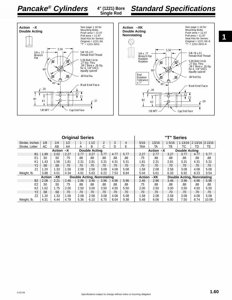
1
Specifications subject to change without notice or incurring obligation
Pancake® Cylinders
1.60
Standard Specifications4" (1221) BoreSingle Rod
4-22-04
Stroke, Inches 1/8 1/4 1/2 1 1 1/2 2 3 4 5/16 13/16 1 5/16 1 13/16 2 13/16 3 13/16Stroke, Letter AC AB AA A B C D E TAA TA TB TC TD TE
B1 1.89 2.02 2.27 2.77 3.27 3.77 4.77 5.77 2.27 2.77 3.27 3.77 4.77 5.77E1 .50 .50 .75 .88 .88 .88 .88 .88 .75 .88 .88 .88 .88 .88K1 1.43 1.56 1.81 2.31 2.81 3.31 4.31 5.31 1.81 2.31 2.81 3.31 4.31 5.31Y1 .58 .58 .70 .70 .70 .70 .70 .70 .70 .70 .70 .70 .70 .70Z1 1.20 1.33 1.58 2.08 2.58 3.08 4.08 5.08 1.58 2.08 2.58 3.08 4.08 5.08
Weight, lb. 3.88 4.01 4.34 4.91 5.63 6.22 7.53 8.84 5.04 5.61 6.33 6.92 8.23 9.54
B2 2.08 2.21 2.46 2.96 3.46 3.96 4.96 5.96 2.46 2.96 3.46 3.96 4.96 5.96E2 .50 .50 .75 .88 .88 .88 .88 .88 .75 .88 .88 .88 .88 .88K2 1.62 1.75 2.00 2.50 3.00 3.50 4.50 5.50 2.00 2.50 3.00 3.50 4.50 5.50Y2 .58 .58 .70 .70 .70 .70 .70 .70 .70 .70 .70 .70 .70 .70Z2 1.20 1.33 1.58 2.08 2.58 3.08 4.08 5.08 1.58 2.08 2.58 3.08 4.08 5.08
Weight, lb. 4.31 4.44 4.78 5.36 6.10 6.70 8.04 9.38 5.48 6.06 6.80 7.50 8.74 10.08
Original Series "T" Series
Action –XK Double Acting, Nonrotating
Action –X Double Acting
Action –XK Double Acting, Nonrotating
Action –X Double Acting
Action –XDouble Acting
See page 1.16 forMounting Bolts.Push area = 12.57Pull area = 11.97Seal Kits for Series:Original = 1221-SK"T" = 1221-SKG
Action –XKDouble ActingNonrotating
See page 1.16 forMounting Bolts.Push area = 12.47Pull area = 11.87Seal Kits for Series:Original = 1221-SK-K"T" = 1221-SKG-K
5/8-18 x E1Female Rod Thread
5.00 Bolt Circle .27 Dia. Thru.38 C'Bore x .26 Dp.for 4, 1/4" SHCSequally spaced
5.503/4 x .17Wrench Flat
.88 Rod Dia.
45°
.20
B1K1
1/8 NPT
Rod End Face
Y1Z1
Cap End Face
.31
90°
5/8-18 x E2Female Rod Thread
5.00 Bolt Circle .27 Dia. Thru.38 C'Bore x .26 Dp.for 4, 1/4" SHCSequally spaced
5.503/4 x .17Wrench FlatRandomRotation
.88 Rod Dia.
45°
.20
B2K2
1/8 NPT
Rod End Face
Y2Z2
Cap End Face
.50
90°RodRotationTolerance± 1°

1
Pancake® Cylinders
Specifications subject to change without notice or incurring obligation1.61
Option Specifications4" (1221) BoreAlso See Page 1.60
.63
1.22
2.00
Oil filled bushings
1.44 + B
1.06
.63 2.24
-PMPort LocationIN LINE with Slot -SM
Port Location90° to Slot
Also see page 1.60
Note 1
12-15-04
Suffix Options -PM & -SM Clevis MountAvailable on Original and “T” Serieswith Actions: -X, -XKAlso see Option Information on page 1.13.
EM-1221 Eye Bracket KitMates with Clevis Mount shown on the left.Order separately.
RC-63 Rod Clevis and PinThreaded Stud mates with Female Rod threadin the Pancake® Cylinders.Slot and Pin Mate with EM-521 Eye Bracketshown on the right.
EM-521 Eye Bracket KitMates with RC-63 Rod Clevis shown on the left.Order separately.
Note 1:Hole Diameter = .626Pin Diameter = .625Pin (416 Stainless Steel)and Clips are included.
1.00 1.10
2.63
.38
2.25
2.501.75
Hole .626Oil filled bushingis standard
.58
1.50 1.63
.34 Dia. 4 Places for Flat Head ScrewsFour 5/16-18 x 1"FHSCS are included
Material: Zinc Die Casting
.751.13
2.25
.38
2.00
2.001.38
Hole .501Oil filled bushingis standard
.47
1.38 1.50.33 Dia. 4 Placesfor Flat Head ScrewsFour 5/16-18 x 1"FHSCS are included
Material: Zinc Die Casting
The Suffix Options charted on the right are available on Originaland “T” Series with the Actions indicated (✓ ). They require nodimensional changes from the Standard Specifications on page1.60. – Also see Option Information on pages 1.7 thru 1.15.
T V Q H N C1–C7 LF LR LFR BF BR BFR P14
-X ✓ ✓ ✓ ✓ ✓ ✓ ✓ ✓ ✓ ✓ ✓ ✓ ✓
-XK NA ✓ ✓ ✓ ✓ ✓ ✓ ✓ ✓ ✓ ✓ ✓ ✓
Prefix Option -M Metric Cylinder & Rod Thread 101.6mm BoreAvailable on Original and “T” Series with Actions: -X, -XKAlso see Option Information on page 1.7.
127.0mm Bolt Circle
G1/8 Ports with 14mm Spotface
M16 x 31.8
Standard Female Rod Thread M16.Male Rod ThreadOption -MR shown.
Mounting Holes6.7mm Diameter Thru10.3mm C'Bore x 6.4mm Dp.4 Places for M6 SHCS
Thread PitchesM6 = 1.0mmM16 = 2.0mm
Conversion FactorInches x 25.4 = mmStroke mm 3.2 6.4 12.7 25.4 38.1 50.8 76.2 101.6
Stroke Letter AC AB AA A B C D E
Stroke mm 7.9 20.6 33.3 46.0 71.4 96.7Stroke Letter TAA TA TB TC TD TE
Original Series
“T” Series
.50
Pin Diameter .500
5/8-18 x .75Optional Metric#MRC-63M16 x 19.0
2.13
1.63
1.62 .94 . 80
Materials:Clevis – Steel, Black OxideStud – SteelPin – 416 StainlessSteelPin & Clips are included
1.38

1
Specifications subject to change without notice or incurring obligation
Pancake® Cylinders
1.62
Option Specifications4" (1221) BoreAlso See Page 1.60
45°
30°30°#1#2
Sensors available for “AB” & “TAA” strokes and longer. AB – A & TAA – TA have 2 mounting slots; others have 1.
4" (1221) Bore Quick Reference to Standard StrokesUse the appropriate Stroke Letter in the Model Number
1/4" 60° Dovetail Profile ofSensor & Mounting Slot for3/4" bore Pancakes & up.
As shown at the right, longerstrokes are furnished with asingle mounting slot locatedat position #1.
Shorter strokes arefurnished with a second slotat position #2.
Available on Original Series
ActionStroke X, XK
1/4 ----------------- AB1/2 ----------------- AA1 -------------------- A1 1/2 --------------- B2 -------------------- C3 -------------------- D4 -------------------- E
Available on“T” SeriesAction
Stroke X, XK
5/16 --------------- TAA13/16 -------------- TA1 5/16 ------------- TB1 13/16 ----------- TC2 13/16 ----------- TD3 13/16 ----------- TE
Suffix Option -E Specifies Magnetic Piston and Dovetail Mounting Slot(s)Strokes are NOT affected by magnetic piston.
– Sensors Must be Ordered SeparatelySee Sensor Models Available page 1.14
BB C
ED
2.00 Dia.
1.50 Dia.
.063 Stroke AdjustmentPer Revolution
Suffix Option -AS Adjustable Extend StrokeAvailable on Original Series with Actions: -X, -XKAlso see Option Information on page 1.11.
Stroke Inches 1/8 1/4 1/2 1 1-1/2 2 3 4Stroke Letter AC AB AA A B C D E
BB 2.33 2.45 2.70 3.20 3.70 4.20 5.20 6.20C 1.66 1.91 2.41 3.41 4.41 5.41 7.41 9.41D 0.63 .75 1.00 1.50 2.00 2.50 3.50 4.50E 0.88 1.00 1.25 1.75 2.25 2.75 3.75 4.75
.19
.19 + B(-XK only use B2 as shown on page 1.60. No additional length is required.)
11/16 Hex Nut
.050 Stroke AdjustmentPer Revolution
Adjusting Screw
Strokes 1" & Shorter = .38 Max. + StrokeStrokes 1" & Longer = .38 + AdjustmentStandard Adjustment is 1"
Suffix Option -RS Adjustable Retract StrokeAvailable on Original and “T” Serieswith Actions: -X, -XKAlso see Option Information on page 1.11.
Suffix Option -HHC Hydraulic & -HC AirAvailable on Original and “T” Series with Action -X.Also see Option Information on page 1.9.
Suffix Option -MR Male Rod ThreadAvailable on Originaland “T” Series withActions: -X, -XKAlso see Option Informationon page 1.8.
5/8-18 x 1.25
.19 + B.19 + K
.50
4-9-04

1
Pancake® Cylinders
Specifications subject to change without notice or incurring obligation
Stroke, Inches 1/8 1/4 1/2 1 1 1/2 2 3 4Stroke, Letter AC AB AA A B C D E
B 2.33 2.45 2.70 3.20 3.70 4.20 5.20 6.20E .50 .50 .75 .88 .88 .88 .88 .88K 1.87 2.00 2.25 2.75 3.25 3.75 4.75 5.75Y .58 .58 .70 .70 .70 .70 .70 .70Z 1.20 1.33 1.58 2.08 2.58 3.08 4.08 5.08
Weight, lb. 5.22 5.38 5.75 6.44 7.16 7.72 9.19 10.31
1.63
4" (1221) BoreDouble Rod
Standard Specifications
Action –XDR Original SeriesDouble Rod, Double Acting
5/8-18 x EFemale Rod Thread
5.00 Bolt Circle .27 Dia. Thru.38 C'Bore x .26 Dp.for 4, 1/4" SHCSequally spaced
5.503/4 x .17Wrench Flat
.88 Rod Dia.
45°
.20
BK
1/8 NPT
Rod End Face
YZ
Cap End Face
.75
90°
.20 + Stroke
See page 1.16 forMounting Bolts.Force area = 11.97Seal Kit = 1221-SK
Action –XDRK Original SeriesDouble Rod, Double Acting, Nonrotating
Stroke, Inches 1/8 1/4 1/2 1 1 1/2 2 3 4Stroke, Letter AC AB AA A B C D E
B 2.33 2.45 2.70 3.20 3.70 4.20 5.20 6.20E .50 .50 .75 .88 .88 .88 .88 .88K 1.87 2.00 2.25 2.75 3.25 3.75 4.75 5.75Y .58 .58 .70 .70 .70 .70 .70 .70Z 1.20 1.33 1.58 2.08 2.58 3.08 4.08 5.08
Weight, lb. 5.65 5.81 6.19 6.89 7.63 8.23 9.70 10.85
5/8-18 x EFemale Rod Thread
5.00 Bolt Circle .27 Dia. Thru.38 C'Bore x .26 Dp.for 4, 1/4" SHCSequally spaced
5.503/4 x .17Wrench FlatRandomRotation
.88 Rod Dia.
45°
.20
BK
1/8 NPT
Rod End Face
YZ
Cap End Face
.75
90°RodRotationTolerance± 1°
.20 + Stroke
See page 1.16 forMounting Bolts.Force area = 11.87Seal Kit = 1221-SK-K
10-23-04

1
Specifications subject to change without notice or incurring obligation
Pancake® Cylinders
1.64
Option Specifications4" (1221) BoreAlso See Page 1.63
4-22-04
4" (1221) Bore
1/4" 60° Dovetail Profile ofSensor & Mounting Slot for3/4" bore Pancakes & up.
As shown at the right, longerstrokes are furnished with asingle mounting slot locatedat position #1.
Shorter strokes arefurnished with a second slotat position #2.
45°
30°30°#1#2
Sensors available for “AB”strokes and longer. AB – A have 2 mounting slots; others have 1.
Suffix Option -E Specifies Magnetic Piston and Dovetail Mounting Slot(s)Strokes are NOT affected by magnetic piston.
127.0mm Bolt Circle
G1/8 Ports with 14mm Spotface
M16 x 31.8
Standard Female Rod Thread M16.Male Rod ThreadOption -MR shown.
Mounting Holes6.7mm Diameter Thru10.3mm C'Bore x 6.4mm Dp.4 Places for M6 SHCS
Thread PitchesM6 = 1.0mmM16 = 2.0mm
Conversion FactorInches x 25.4 = mm
Prefix Option MMetric Cylinder & Rod Thread101.6mm Bore
Available on Original Series withActions -XDR, -XDRK.Also see Option Information on Page 1.7
5/8-18 x 1.25
Suffix Options -MR, -MR1, -MR2 Male Rod Thread
Available on Original Series with Actions -XDR, -XDRK.
For Rod End only use –MRFor Cap End only use –MR1For Both Ends use –MR2
Also see Option Information on Page 1.8
The Suffix Options charted on the right are available onOriginal Series with the Actions indicated (✓ ). They requireno dimensional changes from the Standard Specificationson page 1.63. – Also see Option Information on pages 1.7thru 1.15.
T V Q H N C1–C7 LF LR LFR BF BR BFR P14 25
-XDR ✓ ✓ ✓ ✓ ✓ ✓ ✓ ✓ ✓ ✓ ✓ ✓ ✓ ✓
-XDRK NA ✓ ✓ ✓ ✓ ✓ ✓ ✓ ✓ ✓ ✓ ✓ ✓ ✓
Quick Reference to Standard StrokesUse the appropriate Stroke Letter in the Model Number
Available on Original Series
ActionStroke XDR, XDRK
1/4 ----------------- AB1/2 ----------------- AA1 -------------------- A1 1/2 --------------- B2 -------------------- C3 -------------------- D4 -------------------- E
– Sensors Must be Ordered SeparatelySee Sensor Models Available page 1.14
Stroke mm 3.2 6.4 12.7 25.4 38.1 50.8 76.2 101.6
Stroke Letter AC AB AA A B C D E

1
Pancake® Cylinders
Specifications subject to change without notice or incurring obligation1.65
External Guide Pins Provide Load Guiding
External guide pins, adapted to the Pancake®cylinder line provide a superior nonrotating pistonrod feature for applications such as package place-ment, figure stamping, and any application whereanti-rotation and registration are critical as thepiston is extended and retracted.
A mounting block is bolted to the piston rod. Thisblock has two square pins mounted to it which inturn pass through guide blocks mounted on thesides of the cylinder.
Square guide pins are hard chrome platedsteel for long wear and corrosion resistance.
Guide blocks are hard anodized aluminumfor long wear and corrosion resistance.
Clearance in guide block mounting holes pro-vide for adjustment and backlash control,compensation for wear, and minimal rotation.
Extended distance between guides providessuperior nonrotation and support.
Extended piston rod provides clearancebetween cylinder and guide bar mountingblock to eliminate pinch points.
Available on Pancake® cylinders:Original and "T" Series
Bores: 3/4" (7), 1 1/8" (121), 1 5/8" (221),2" (321), 2 1/2" (521), 3" (721),and 4" (1221)
Strokes: 1/8" through 4"
Actions: –X, –XDR
In combination with Options:Suffix;-T, -V, -Q, -H, HHC, -HC,-P14,-N, -C1 –– -C7, -AS, -RS, -LF,-LR, -LFR, -BF, -BR, -BFR, -E
HOW TO ORDERSelect the basic Pancake® Cylinder modelnumber for your desired series, bore andstroke. Then add -G as a Suffix Option.
Please Note!!This option affects the rod end dimensionsSee details on page 1.66.
Model G-221-X-G Shown
4-9-04
External Guide Pins
Also available in Square 1® cylinders:Bores 3/4" through 2" Strokes 1/8" through 6"See page 2.14 of this catalog.

1
Specifications subject to change without notice or incurring obligation
Pancake® Cylinders
1.66
PP Square Guide PinsHard Chrome Steel Plated
Mounting BlockClear AnodizedAluminum
Guide BlockHard Anodized Aluminum
NN
NN2
SS
RR
RR2
VVMounting Holes2 Places
UU
TT
JJRef.
LL
MM
B + 0.50
Clearance in Guide Block mounting holes allows for adjustment to compensate for wear
90°45°
1-28-00
3/4" through 2" Bores 2 1/2" through 4" Bores
For dimensions B and all other dimensions not noted, please refer back to the maindimension table associated with your cylinder model and option selections.
Use the CAD library of Pancake® cylinders with your CAD program to reduce design time.
External Guide Pins
Model 521 721 1221Bore 2 1/2" 3" 4"
JJ 3.74 4.24 5.50LL 0.64 0.64 0.70MM 0.75 1.00 1.25NN 4.56 5.06 6.32PP 0.31 0.31 0.31RR 1.88 1.88 1.88SS 4.88 5.38 7.09TT 1.00 1.00 1.00UU 1.00 1.00 1.25VV 5/16-18 5/16-18 5/16-18
Model 7 121 221 321Bore 3/4" 1 1/8" 1 5/8" 2"
JJ 1.50 1.99 2.74 3.24LL 0.63 0.64 0.64 0.64MM 0.63 0.63 0.63 0.75NN 2.20 2.75 3.50 4.00PP 0.19 0.25 0.25 0.25RR 0.88 1.06 1.50 1.88SS 2.30 3.13 3.85 4.37TT 0.75 1.00 1.00 1.00UU 0.63 0.63 0.75 1.00VV #6-32 #8-32 1/4-20 5/16-18ZZ 45° 45° 45° 63°
PP Square Guide PinsHard Chrome Steel Plated
Mounting BlockClear AnodizedAluminum
Guide BlockHard Anodized Aluminum
NN
NN2
45° ZZ
SS
RR
RR2
VVMounting Holes2 Places
UU
TT
JJRef.
LL
MM
B + 0.50
Clearance in Guide Block mounting holes allows for adjustment to compensate for wear

Specifications subject to change without notice or incurring obligation
2
Square 1® Air Cylinders
Page
General Standard Ratings and Sizing Guide .............................................. 2.2
Construction Details .................................................................................... 2.3, 2.4How a Square 1® is built
Standard Specifications .............................................................................. 2.5
Model Number Codes ................................................................................. 2.6
Option List ................................................................................................... 2.6
How to Order ............................................................................................... 2.6
Standard Specifications (Dimension Details) .............................................. 2.7, 2.8
Option Specifications .................................................................................. 2.9 - 2.14Description and Dimensionsof the Options
Mounting Kits for SQF and SQFW
Flange Mounting Kits ..................................................................... 2.14Trunnion Mounting Kits .................................................................. 2.15Clevis Bracket Kits ......................................................................... 2.15Eye Bracket Kits ............................................................................. 2.15Rod Clevises .................................................................................. 2.15
Accessories
Flow Controls, Port Mounted and Others ....................................... Section 12Position Sensors ............................................................................ 2.13Mounting Bolts ............................................................................... Section 1.16Wrench Flat Wrench ...................................................................... Section 1.16
Air Spring Return ........................................................................................ Section 1.15
2 Year Warranty ........................................................................................... Inside back cover
2.1 4-7-03

Specifications subject to change without notice or incurring obligation
2
Bore Diameter 3/4" 7/8" 1-1/8" 1-5/8" 2"Rod Diameter 0.3125 0.3125 0.500 0.625 0.750Rod Area 0.08 0.08 0.19 0.31 0.44Push Area (Single Rod) 0.44 0.60 0.99 2.07 3.14Pull Area 0.36 0.52 0.80 1.76 2.70SQ & SQF Base Weight, lb. 0.18 – 0.31 0.63 1.05SQL Base Weight, lb. – 0.18 0.33 0.70 1.16Weight Per Inch, lb. 0.13 0.13 0.19 0.32 0.45
10-23-04
• Double acting, single rod• Duralon® rod bushing• Female rod end with wrench flats• Internally lubricated Buna-N O-ring
piston and rod seals.• Ports at position #1
• Media . . . . . . . . . . . . . . . . . . . . Air, Optional Hydraulic• Max. operating pressure . . . . . . 150 psi Air or Hydraulic• Min. operating pressure recommended . . . . . . . 10 psi• Ambient & media temperature range . . -25° to +250°F• Prelubrication . . . . . . . . . . . . . . Magnalube®–G Grease• Air Line Lubrication . . . . . . . . . . . . . . . . Recommended• Stroke tolerance . . . . . . . . . . . . . . . . . . . . . . . . . ± 1/64"
Square 1® Cylinders
Ratings – Standard Units all series
Sizing Guide
Series SQ, Side Tap Mount
Series SQF, Face Mount
Series SQL, Side Lug Mount
Load Capacity (psi)Machine Design 1972/73Bearing Reference Issue
Porous Bronze ............ 4,500Porous iron ................ 8,000Phenolics ................... 6,000Nylon® ....................... 1,000TFE ............................ 500Reinforced Telfon® .... 2,500*TFE fabric ................ 60,000Polycarbonate ............ 1,000Acetal ........................ 1,000Carbon-graphite ........ 600
* Shows Duralon bearing classification. Not to be used for design purposes.
Friction PropertiesSlip-
Coefficient stickSteel-on-steel ............... .50 YesBronze-on-steel ............. .35 YesSintered Bronze-on-steel with mineral oil ...... .13 NoBronze-on-steel with mineral oil ...... .16 NoCopper lead alloy-on-steel .22 YesAcetal-on-steel ............. .20 NoNylon-on-steel ............. .32 YesDuralon-on-steel .......... .05 - .16 No
Duralon® Rod Bearings Excel
Printed with permission by Rexnord Corp.
Heavy wall construction, hardanodized inside and out
Piston Seal, internallylubricated O'Ring forlong life and improvedperformance
PTFE Bearing Strip, for stroke 1"and over, is located away from rodbearing for maximum load support
Piston Rod Bushing, hard anodizedaluminum housing with Teflon®
lined Duralon® insert
Crosshatch polished bore for lubricationretention and longer seal life
Hard chrome plated stainlesssteel piston rod
Available in 3 styles5 Bore sizes 3/4" thru 2"Strokes to 6"
Side view (opposite ports)shows mounting holes andrelief for mounting rails.
2.2

Specifications subject to change without notice or incurring obligation
2
2 2
2
5
1
4-7-03
Square 1® Cylinders
66
10
12
1311134
9
13
13 5
66
10
13
11
134
9
13
13 5
12
5
2 21
2
5
2 23
32
8
Bowed
6
Rectangular
13
13
8
Series SQ Series SQF Series SQL
Strokes 1" and overStrokes under 1"
7
2" Bore3/4", 7/8"1-1/8", 1-5/8"
Bores
8
2.3
13
6
13
7
Beveled
7
Rectangular
Standard Single Rod Models ShownDouble Rod: See Option -DR page 2.10Nonrotating: See Option -K page 2.12
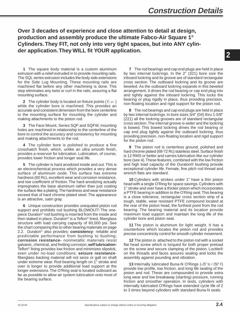
Specifications subject to change without notice or incurring obligation
2
Construction Details
10-23-04 2.4
1 The square body material is a custom aluminumextrusion with a relief extruded in to provide mounting rails.The SQL series extrusion includes the body side extensionsfor the Side Lug Mounting. These mounting rails aremachined flat before any other machining is done. Thisstep eliminates any twist or curl in the rails, assuring a flatmounting surface.
2 The cylinder body is located on fixture points ( )while the cylinder bore is machined. This provides anaccurate and consistent dimension from the bore centerlineto the mounting surface for mounting the cylinder andmaking attachments to the piston rod.
3 The Face Mount, Series SQF and SQFW, mountingholes are machined in relationship to the centerline of thebore to control the accuracy and consistency for mountingand making attachments to the rod.
4 The cylinder bore is polished to produce a finecrosshatch finish, which, unlike an ultra smooth finish,provides a reservoir for lubrication. Lubrication, of course,provides lower friction and longer seal life.
5 The cylinder is hard anodized inside and out. This isan electrochemical process which provides a very densesurface of aluminum oxide. This surface has extremehardness (60 Rc), excellent wear and corrosion resistance,and low coefficient of friction. The hard anodizing actuallyimpregnates the base aluminum rather than just coatingthe surface like a plating. The hardness and wear resistanceexceed that of hard chrome plated steel. The appearanceis an attractive, satin gray.
6 Unique construction provides unequaled piston rodsupport and prohibits rod bushing BLOWOUT! The one-piece Duralon® rod bushing is inserted from the inside andthen staked in place. Duralon® is a Teflon® lined, fiberglassstructure with load carrying capacity of 60,000 psi. Seethe chart comparing this to other bearing materials on page2.2. Duralon® also provides: consistency- reliable andpredictable performance from bushing to bushing;corrosion resistance- nonmetallic materials resistgalvanic, chemical, and fretting corrosion; self lubrication-Teflon® lining provides low friction and minimizes slipstick,even under no-load conditions; seizure resistance-fiberglass backing material will not seize or gall on shaftunder extreme wear. Rod bearing length on 1" stroke andover is longer to provide additional load support at thelonger extensions. The O'Ring seal is located outboard asfar as possible to allow air system lubrication onto most ofthe bearing surface.
7 The rod bearings and cap end plugs are held in placeby two internal lockrings. In the 2" (321) bore size theinboard lockring and its groove are of standard rectangularcross section. The outboard lockring and its groove arebeveled. As the outboard lockring expands in this beveledarrangement, it drives the rod bearing or cap end plug intoand tightly against the inboard lockring. This locks thebearing or plug rigidly in place, thus providing precision,non-floating location and rigid support for the piston rod.
8 The rod bearings and cap end plugs are held in placeby two internal lockrings. In bore sizes 3/4" (04) thru 1-5/8"(221) all the lockring grooves are of standard rectangularcross section. The internal groove is wider and the lockringis bowed. This bowed lockring drives the rod bearing orcap end plug tightly against the outboard lockring, thusproviding precision, non-floating location and rigid supportfor the piston rod.
9 The piston rod is centerless ground, polished andhard chrome plated (68-72 Rc) stainless steel. Surface finishis 12 RMS or better and carries lubrication like our cylinderbore (see 4). These features, combined with the low frictionand high load capacity of the Duralon® bushing provideexceptional cylinder life. Female, fine pitch rod thread andwrench flats are standard.
10 Cylinders with strokes under 1" have a thin pistonhead with a single O'Ring for space savings. Cylinders with1" stroke and over have a thicker piston which incorporatesa PTFE bearing in addition to the O'Ring seal. This bearingis a close tolerance, rectangular cross section strip of atough, stable, wear resistant PTFE compound located atthe rear of the piston head, the furthest point from the rodbearing. The bearing material and its location providemaximum load support and maintain the long life of thecylinder bore and piston seal.
11 The piston is aluminum for light weight. It has acounterbore which locates the piston rod and providesprecise concentricity control for smooth cylinder movement.
12 The piston is attached to the piston rod with a socketflat head screw which is torqued for both proper preloadon the screw and secure clamping of the piston. Loctite®on the threads and faces assures sealing and locks theassembly against pounding and vibration.
13 Internally lubricated Buna-N O'Rings (–25° to + 250° F)provide low profile, low friction, and long life sealing of thepiston and rod. These are compounded to provide extralong wear and low breakaway (starting) pressure, runningfriction and smoother operation. In tests, cylinders withinternally lubricated O'Rings have extended cycle life of 2to 3 times beyond cylinders with standard Buna-N seals.
➱ ➱
Over 3 decades of experience and close attention to detail at design,production and assembly produce the ultimate Fabco-Air Square 1®
Cylinders. They FIT, not only into very tight spaces, but into ANY cylin-der application. They WILL fit YOUR application.

Specifications subject to change without notice or incurring obligation
2
Bore Series Available Stroke Lengths (Inches)
1/8 1/4 1/2 3/4 1 1-1/2 2 3 4 5 6
7/8" SQL06 ✔ ✔ ✔ ✔ ✔ ✔ ✔ ✔ ✔ NA NA
1-1/8" SQL 121 ✔ ✔ ✔ ✔ ✔ ✔ ✔ ✔ ✔ ✔ ✔
1-5/8" SQL 221 ✔ ✔ ✔ ✔ ✔ ✔ ✔ ✔ ✔ ✔ ✔
2" SQL 321 ✔ ✔ ✔ ✔ ✔ ✔ ✔ ✔ ✔ ✔ ✔
Bore Series Available Stroke Lengths (Inches)
1/8 1/4 1/2 3/4 1 1-1/2 2 3 4 5 6
3/4" SQ04 ✔ ✔ ✔ ✔ ✔ ✔ ✔ ✔ ✔ NA NA
1-1/8" SQ121 ✔ ✔ ✔ ✔ ✔ ✔ ✔ ✔ ✔ ✔ ✔
1-5/8" SQ221 ✔ ✔ ✔ ✔ ✔ ✔ ✔ ✔ ✔ ✔ ✔
2" SQ321 ✔ ✔ ✔ ✔ ✔ ✔ ✔ ✔ ✔ ✔ ✔
Side Tap Mounting: Series SQ
Face Mounting: Series SQF
Bore Series Available Stroke Lengths (Inches)
1/8 1/4 1/2 3/4 1 1-1/2 2 3 4 5 6
3/4" SQF04 ✔ ✔ ✔ ✔ ✔ ✔ ✔ ✔ ✔ NA NA
1-1/8" SQF 121 ✔ ✔ ✔ ✔ ✔ ✔ ✔ ✔ ✔ ✔ ✔
1-5/8" SQF 221 ✔ ✔ ✔ ✔ ✔ ✔ ✔ ✔ ✔ ✔ ✔
2" SQF 321 ✔ ✔ ✔ ✔ ✔ ✔ ✔ ✔ ✔ ✔ ✔
Model SQ 121-2
Model SQF 121-2
Model SQL 121-2
Side Lug Mounting: Series SQL
All Square 1® Mountings
Magnetic piston option does NOT affect stroke.
Magnetic piston option does NOT affect stroke.
Magnetic piston option does NOT affect stroke.
4-7-03
■ Double Acting – Single RodChoice of "G" or "W" Rod Extension*
■ For single acting use air spring as shownon page 1.15
■ Double Acting – Double RodChoice of combinations of "G" and "W" rod extensions*
■ Female Rod End with Wrench Flats■ PTFE Piston Bearing; 1" Stroke and Up■ Internally lubricated Buna-N Seals (-25° to + 250°F)■ Operation to 150 psi■ Rod and Cap End Ports in Position 1A
*For Rod Extension Information See Dimension "G"and "W" on pages 2.6, 2.7 or 2.8.
CAD Drawings on CD-ROM
A complete library of cylinder CAD draw-ings is available. Contact your local dis-tributor for details, download from our website http://www.fabco-air.comor E-Mail us at [email protected]
Standard Specifications
Side view (opposite ports)shows mounting holes and
relief for mounting rails.
2.5

Specifications subject to change without notice or incurring obligation
2
Model Number Code
OPTIONSDescription Specify See Page
Male Rod Thread 2.9Single Rod -MRDouble Rod, Rod End -MRDouble Rod, Cap End -MR1Double Rod, Both Ends -MR2
Viton Seals (-15° to +400°F) -V 2.9Quad Seals -Q 2.9Metric Rod Thread -M 2.9Nonrotating -K 2.12
1-1/8", 1-5/8", 2" bores onlyPort Positions -1B 2.9External Guide, Nonrotating -G 2.14Hydraulic, Low Pressure -H 2.9
to 150 psi NONSHOCKDouble Rod -DR 2.10Hole Thru Double Rod Shaft 2.10
Bore Hole3/4", 7/8" 1/16" -DR061-1/8" 1/8" -DR13 Plus size 5/32" -DR161-5/8" 1/8" -DR13 Plus size 1/4" -DR252" 5/32" -DR16 Plus size 5/16" -DR31
Stroke Collar 1/8" C1 2.111/4" C23/8" C31/2" C45/8" C53/4" C67/8" C7
Sound Limiters 2.11Rod End -LFCap End -LRBoth Ends -LFR
Adjustable Retract Stroke -RS 2.11For over 1" adjustment adddesired length: e.g. -RS2
Magnetic Piston & mounting slot(s) 2.13for Piston Position Sensors -E(Order Sensors separately.)
– –121 2 MR
Mounting
SQSide Tap
SQFFace
SQLSide Lug
Bore
04 for3/4" bore
06 for7/8" bore
121 for1 1/8" bore
221 for1-5/8" bore
321 for2" bore
Rod Extension
Single RodModels
Blank –for standardextension per dimen-sion "G" on page 2.7
W - for Extensionto dimension "W"on page 2.7
Double RodModels
See Page 2.10
Blank –"G" extensionboth ends
W –"W" extensionboth ends
GW – "G" extensionon rod end; "W" exten-sion on cap end
WG – "W" extensionon rod end; "G" exten-sion on cap end
StandardStrokesInchesBores3/4"7/8"1/81/41/23/41
1-1/2234
Bores1-1/8"1-5/8"
2"1/81/41/23/41
1-1/223456
SQ
How to Order1. Specify Mounting Series including Rod Extension Information2. Specify Bore3. Specify Stroke in Inches and Fractions4. Specify Options
ExamplesSQ 121 - 2Side Tap Mounting with "G" Rod Extension;1-1/8" Bore; 2" Stroke
SQW 121 -2 - MRSide Tap Mounting with "W" Rod Extension;1-1/8" Bore; 2" Stroke; Male Rod Thread
SQLW 06 - 3 - C2 - LRSide Lug Mounting with "W" Rod Extension;7/8" Bore; 3" Stroke with 1/4" Stroke Collar yielding2-3/4" Net Stroke; Sound Limiter, Cap End
Mounting Kits for Series SQF Type See PageFlange Mount Kit 2.14Trunnion Mount Kit 2.15Clevis Bracket Kit 2.15Eye Bracket Kit 2.15Rod Clevis 2.15
How To Order
7-2-01 2.6

Specifications subject to change without notice or incurring obligation
2 G or WY Z + Stroke
A–2
A
X
B + Stroke
M + StrokeL
RodEnd
Face
CapEnd
FaceN1
1
2
3
4
K1
K1–2
J (Ref.)
E
Port Position
1B
H
Port Position
1A
A–2
A
PF
G or WY
Z + StrokeB + Stroke
L N1
P
Cylinders with less than 1" stroke have 2 mounting holes
Cylinders with 1" stroke or more have 4 mounting holes
SQ Series: Side Tap Mounting – 3/4", 1-1/8", 1-5/8" and 2" Bores
4-7-03
Square 1® Cylinders
2.7
G or W
A–2
A
X
1
2
3
4
K2
K2––2
J (Ref.)J (Ref.)
T2E S2
Port Position
1B
H
Port Position
1A
A–2
A
F G or WY Z + Stroke
B + Stroke
RodEnd
Face
P
Y
Z + StrokeB + Stroke
L N2
P
M + StrokeL N2
Cylinders with less than 1" stroke have 2 mounting holes
Cylinders with 1" stroke or more have 4 mounting holes
Washer Supplied with cylinder for use under mounting bolt head to prevent cylinder movement while tightening bolt
SQL Series: Side Lug Mounting – 7/8", 1-1/8", 1-5/8" and 2" Bores
Fixed DimensionsA
1.251.251.502.002.50
F Dia..31.31.50.62.75
G.13.13.19.19.19
H1/41/47/161/25/8
J.19.19.19.25.25
K1.88–
1.131.502.00
R.19–
.19
.25
.25
Bore3/4"7/8"
1-1/8"1-5/8"
2"
K2–
1.631.882.503.00
N110-24x.25
–10-24x.251/4-20x.31
5/16-18x.38
U.75–
.75
.75
.75
P10-3210-321/81/81/8
N2–
.21
.21
.27
.27
S1.88–
1.131.502.00
T2–
.02
.02
.03
.03
W.38.38.38
1.001.00
S2–
.19
.19
.25
.31
X.31.31.28.31.38
T11/4-20 x.75dp (Note 2) –1/4-20 x.75dp (Note 2)1/4-20 x.75dp (Note 2)5/16-18 x.75dp (Note 3)
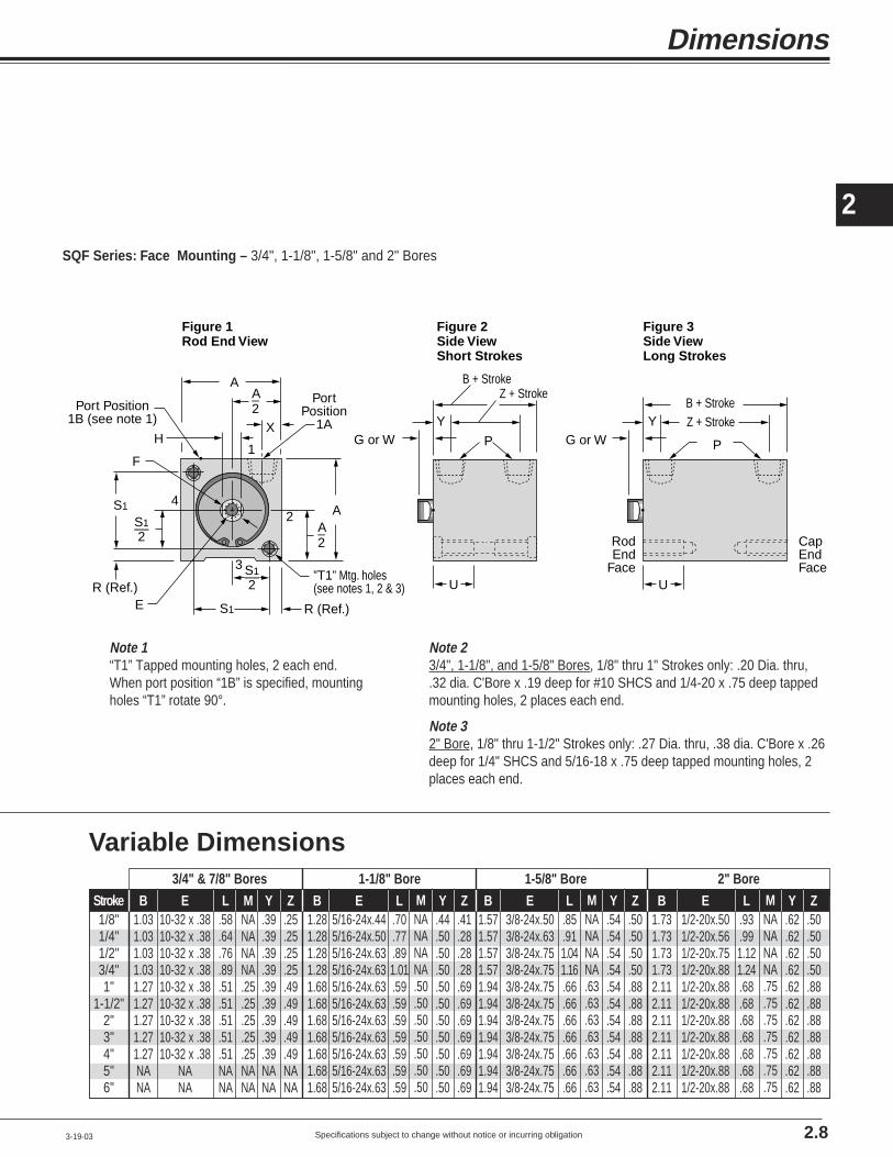
Specifications subject to change without notice or incurring obligation
2
Dimensions
3-19-03
A–2
A
X
1
2
3
4
S1 R (Ref.)E
Port Position 1B (see note 1)
H
Port Position
1A
A–2
A
F
S1
R (Ref.)"T1" Mtg. holes(see notes 1, 2 & 3)
G or WY Z + Stroke
B + Stroke
RodEnd
Face
CapEndFace
P
Y
Z + StrokeB + Stroke
P
UU
S1––2
S1––2
G or W
Figure 2Side ViewShort Strokes
Figure 3Side ViewLong Strokes
Figure 1Rod End View
SQF Series: Face Mounting – 3/4", 1-1/8", 1-5/8" and 2" Bores
2.8
Variable Dimensions
B1.031.031.031.031.271.271.271.271.27NANA
E10-32 x .3810-32 x .3810-32 x .3810-32 x .3810-32 x .3810-32 x .3810-32 x .3810-32 x .3810-32 x .38
NANA
L.58.64.76.89.51.51.51.51.51NANA
Stroke1/8"1/4"1/2"3/4"1"
1-1/2"2"3"4"5"6"
3/4" & 7/8" Bores 1-1/8" Bore 1-5/8" Bore 2" Bore
Y.39.39.39.39.39.39.39.39.39NANA
Z.25.25.25.25.49.49.49.49.49NANA
MNANANANA.25.25.25.25.25NANA
B1.281.281.281.281.681.681.681.681.681.681.68
E5/16-24x.445/16-24x.505/16-24x.635/16-24x.635/16-24x.635/16-24x.635/16-24x.635/16-24x.635/16-24x.635/16-24x.635/16-24x.63
L.70.77.891.01.59.59.59.59.59.59.59
Y.44.50.50.50.50.50.50.50.50.50.50
Z.41.28.28.28.69.69.69.69.69.69.69
MNANANANA.50.50.50.50.50.50.50
B1.571.571.571.571.941.941.941.941.941.941.94
E3/8-24x.503/8-24x.633/8-24x.753/8-24x.753/8-24x.753/8-24x.753/8-24x.753/8-24x.753/8-24x.753/8-24x.753/8-24x.75
L.85.911.041.16.66.66.66.66.66.66.66
Y.54.54.54.54.54.54.54.54.54.54.54
Z.50.50.50.50.88.88.88.88.88.88.88
MNANANANA.63.63.63.63.63.63.63
B1.731.731.731.732.112.112.112.112.112.112.11
E1/2-20x.501/2-20x.561/2-20x.751/2-20x.881/2-20x.881/2-20x.881/2-20x.881/2-20x.881/2-20x.881/2-20x.881/2-20x.88
L.93.991.121.24.68.68.68.68.68.68.68
Y.62.62.62.62.62.62.62.62.62.62.62
Z.50.50.50.50.88.88.88.88.88.88.88
MNANANANA.75.75.75.75.75.75.75
Note 23/4", 1-1/8", and 1-5/8" Bores, 1/8" thru 1" Strokes only: .20 Dia. thru,.32 dia. C'Bore x .19 deep for #10 SHCS and 1/4-20 x .75 deep tappedmounting holes, 2 places each end.
Note 32" Bore, 1/8" thru 1-1/2" Strokes only: .27 Dia. thru, .38 dia. C'Bore x .26deep for 1/4" SHCS and 5/16-18 x .75 deep tapped mounting holes, 2places each end.
Note 1“T1” Tapped mounting holes, 2 each end.When port position “1B” is specified, mountingholes “T1” rotate 90°.
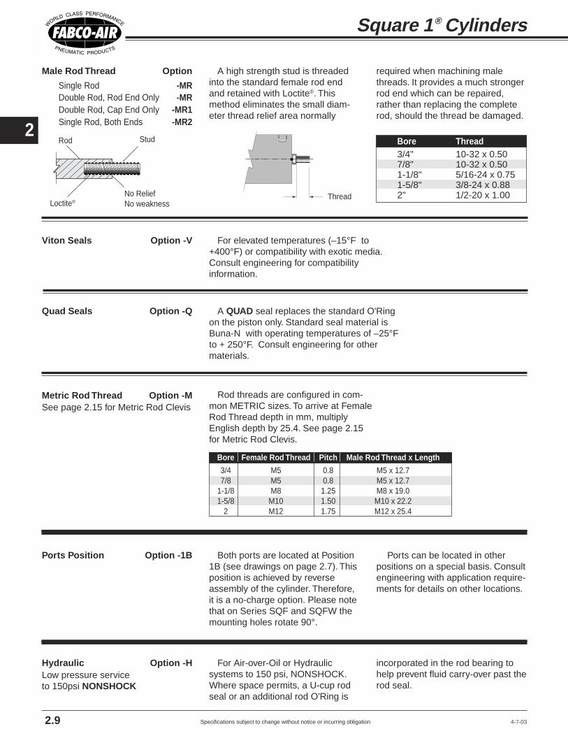
Specifications subject to change without notice or incurring obligation
2
4-7-03
Male Rod Thread Option
Single Rod -MRDouble Rod, Rod End Only -MRDouble Rod, Cap End Only -MR1Single Rod, Both Ends -MR2
Viton Seals Option -V
Metric Rod Thread Option -M
Quad Seals Option -Q
Ports Position Option -1B
Hydraulic Option -H
Square 1® Cylinders
2.9
A high strength stud is threadedinto the standard female rod endand retained with Loctite®. Thismethod eliminates the small diam-eter thread relief area normally
required when machining malethreads. It provides a much strongerrod end which can be repaired,rather than replacing the completerod, should the thread be damaged.
For elevated temperatures (–15°F to+400°F) or compatibility with exotic media.Consult engineering for compatibilityinformation.
Thread
Bore Thread3/4" 10-32 x 0.507/8" 10-32 x 0.501-1/8" 5/16-24 x 0.751-5/8" 3/8-24 x 0.882" 1/2-20 x 1.00
A QUAD seal replaces the standard O'Ringon the piston only. Standard seal material isBuna-N with operating temperatures of –25°Fto + 250°F. Consult engineering for othermaterials.
Both ports are located at Position1B (see drawings on page 2.7). Thisposition is achieved by reverseassembly of the cylinder. Therefore,it is a no-charge option. Please notethat on Series SQF and SQFW themounting holes rotate 90°.
For Air-over-Oil or Hydraulicsystems to 150 psi, NONSHOCK.Where space permits, a U-cup rodseal or an additional rod O'Ring is
Ports can be located in otherpositions on a special basis. Consultengineering with application require-ments for details on other locations.
incorporated in the rod bearing tohelp prevent fluid carry-over past therod seal.
Rod threads are configured in com-mon METRIC sizes. To arrive at FemaleRod Thread depth in mm, multiplyEnglish depth by 25.4. See page 2.15for Metric Rod Clevis.
Rod
Loctite®No ReliefNo weakness
Stud
See page 2.15 for Metric Rod Clevis
Low pressure serviceto 150psi NONSHOCK
Bore Female Rod Thread Pitch Male Rod Thread x Length
3/4 M5 0.8 M5 x 12.77/8 M5 0.8 M5 x 12.7
1-1/8 M8 1.25 M8 x 19.01-5/8 M10 1.50 M10 x 22.2
2 M12 1.75 M12 x 25.4

Specifications subject to change without notice or incurring obligation
2
Option Specifications
7-3-01
Double Rod Option -DR
Hole Thru Double Rod Shaft
Single Rod ModelsBlank– for standard extension
per dimension "G".W– for extension to
dimension "W".
Double Rod ModelsBlank– "G" both ends.
W– "W" extension both ends.GW– "G" extension rod end;
"W" extension cap end.WG– "W" extension rod end;
"G" extension cap end.
G or W + StrokeG or W
Rod End Cap End
Standard piston rod and rodbushing on both ends of the cylin-der.Counterbores on both sides of thepiston maintain concentricity of thepiston rods to each other as wellas to the piston O-ring.
The piston rods are connectedby a high strength stud, sandwich-ing the piston between the rodfaces. The assembly is torqued forproper preload of the stud andclamping of the piston head.Loctite® on the threads and facesassures sealing and locks the as-sembly against pounding and vi-
A hole is drilled through the pis-ton rods and the double rod stud.This hole is used for the passageof Vacuum, Air, Gas, Liquid, or anymedia that is compatible with thestainless steel piston rod and thesteel stud. Maximum pressure is
SQ . . . . . . -DR "G" rod ext. both ends.SQW . . . . -DR "W" rod ext. both ends.SQGW . . . -DR "G" rod ext. rod end;
"W" rod ext. cap end.SQWG . . . -DR "W" rod ext. rod end;
"G" rod ext. cap end.
SQF . . . . . -DR "G" rod ext. both ends.SQFW . . . -DR "W" rod ext. both ends.SQFGW. . -DR "G" rod ext. rod end;
"W" rod ext. cap end.SQFWG. . -DR "W" rod ext. rod end;
"G" rod ext. cap end.
SQL . . . . . -DR "G" rod ext. both ends.SQLW . . . -DR "W" rod ext. both ends.SQLGW . . -DR "G" rod ext. rod end;
"W" rod ext. cap end.SQLWG . . -DR "W" rod ext. rod end;
"G" rod ext. cap end.
2.10
Piston
CounterboresRod
Rod
Stud
bration. This procedure provides apositive and rigid assembly that willnot allow the piston rod to float orbe pounded loose.
The PTFE piston bearing is notrequired because the two rodbushings provide excellent pistonsupport.
Use when attachment to bothends of the cylinder is required orto indicate piston position.
The availability of 2 rod exten-sions offers a number of modelcombinations as shown in the list-ings at the left.
150 psi. The maximum hole sizefor each bore is shown in the chartbelow.
The PTFE piston bearing is notrequired because the two rodbushings provide excellent pistonsupport.
Note: When using stroke collars in double rod units, CAP END ROD STICK-OUTincreases by amount stroke is shortened.
Rod Rod
Piston
StudHole Thru Standard Standard PlusModel No. Model No.
Hole Size Suffix Hole Size SuffixBore thru stud (Std) thru stud (Std Plus)
3/4", 7/8" 1/16 -DR06 – –1-1/8" 1/8 -DR13 5/32 -DR161-5/8" 1/8 -DR13 1/4 -DR25
2" 5/32 -DR16 5/16 -DR31
Rod Extension Dimensions
Bore 3/4" 7/8" 1-1/8" 1-5/8" 2"G .13 .13 .19 .19 .19W .38 .38 .38 1.00 1.00

Specifications subject to change without notice or incurring obligation
2
10-23-04
Stroke Collar on piston rod Option
1/8" -C1
1/4" -C2
3/8" -C3
1/2" -C4
5/8" -C5
3/4" -C6
7/8" -C7
AdjustableRetract Stroke Option -RS
Square 1® Cylinders
2.11
An adjusting screw with a threadsealing locknut mounted in the CapEnd Plug provides a simple, yetrugged and precision adjustment ofthe cylinder stroke in the retractdirection. Bores 3/4", 7/8", and1-1/8" have a 5/16"-24 thread giving0.042" adjustment per revolution.Bores 1-5/8" and 2" have a 1/2-20thread giving 0.050" adjustment perrevolution.
The -RS designation provides fullstroke adjustment of any cylinderwith 1" stroke or less, and 1" strokeadjustment on all longer strokes.When specifying longer adjustmentson longer cylinders, add the desiredadjustment to the -RS designation(1/2" increments, please).
Example: -RS2 will provide 2" ofadjustment on any cylinder with 2"or more stroke.
How to Order1) Start with the nextlongest stroke cylinder.2) Select the amount thestroke is to be shortened.3) Use the correspondingdesignation immediatelyafter the stroke in themodel number.
For those “in-between” strokes, aSTROKE COLLAR of Delrin® isincorporated on the piston rod. Thecollar fits tightly on the piston rod sothat it cannot float as the piston isstroked. Tolerance on the stroke is ±1/64". For tighter tolerances on thestroke or final rod position, contactengineering with application details.
For applications where you need asmall amount of cushion at the endof the cylinder stroke to take out themetallic “slap” of piston head on
piston stop. This is accomplished byplacing an O'Ring on the rod at thepiston, and/or in the cap end plug sothat initial contact is with the elas-tomer and not metal-to-metal.
The Fabco-Air design assuressufficient compression of the sealsto allow full stroke.
Because of the temperaturelimitations of the adhesives involved,sound limiters are available incylinders with internally lubricatedBuna-N O'Rings only.
Stroke collar of Delrin®
Sound Limiters Option
Rod End Only -LFCap End Only -LRBoth Rod & Cap Ends -LFR
Note: When using stroke collars in doublerod units, CAP END ROD STICK-OUT in-creases by amount stroke is shortened.
.17 Max.Adjusting Screw
Thread sealing locknut3/4", 7/8", 1-1/8" Bores = 1/2 Hex1-5/8" and 2" Bores = 11/16 Hex
Strokes 1" & Under = .38 Max. + StrokeStrokes Over 1" = .38 Max. + Adjustment
Any stroke with up to andincluding 1" adjustment. Anystroke with over 1" adjustment,specify the adjustment lengthafter the -RS.Example:
2" Adjustment = -RS2
Sound limiting O'Ring Cushions
Option -LFR shown

Specifications subject to change without notice or incurring obligation
2
Wrench flat random rotation
An internal piston guide pinprohibits rod rotation so that objectsattached to or moved by the rod willnot rotate. Incorporating the guidemechanism inside the cylindersaves you the time, space and costof mounting external guide pins andbushings in and around your mecha-nism. The guide pin and bushing arealso protected from damage by theenvironment, the atmosphere, ormechanical abuse. These internalparts are lubricated by the systemlubrication.
Option Specifications
2.12
Construction Details
1. The aluminum piston is at-tached to the piston rod with asocket flat head cap screw which istorqued for proper preload of thescrew and clamping of the piston.Loctite® on the threads and facesassures sealing and locks theassembly against pounding andvibration.
2. PTFE bearing is standard in1" strokes and longer for single rodmodels.
3. The non-rotating guide pin isground tool steel for precision andlong life. Incorporated inside thecylinder it is protected from environ-mental dirt and grime and mechani-cal abuse. It receives lubrication
Available in 1-1/8", 1-5/8", and 2"bores.
May be used in conjunction withall options including -E pistonposition sensing.
Rotational accuracy is ±1°. Thewarning label shown at the left isapplied to each cylinder.
from the air system lubricator.
4. A precision machined guide pinsupport block is attached to eachend of the cylinder by a flat headscrew. These support blocks providerigid and precise location of theguide pin.
5. The guide pin passes through apolyurethane O-ring seal and anSAE660 bearing bronze bushinginstalled in the piston head. Thiscombination provides "no-leak"precision guiding and long life.
6. A disk of rubber is included atthe end of the guide pin to take upend play and firmly seat the pin in itssupport blocks.
Model SQL 321 - 4 - K shown
Nonrotating Option -K
1-1/8", 1-5/8", and 2" bores only
WARNINGTHIS CYLINDER HAS A NONROTATING ROD.TO PREVENT INTERNAL DAMAGE HOLDROD BY WRENCH FLATS WHEN INSTALLINGOR REMOVING ATTACHMENTS.
10-23-04
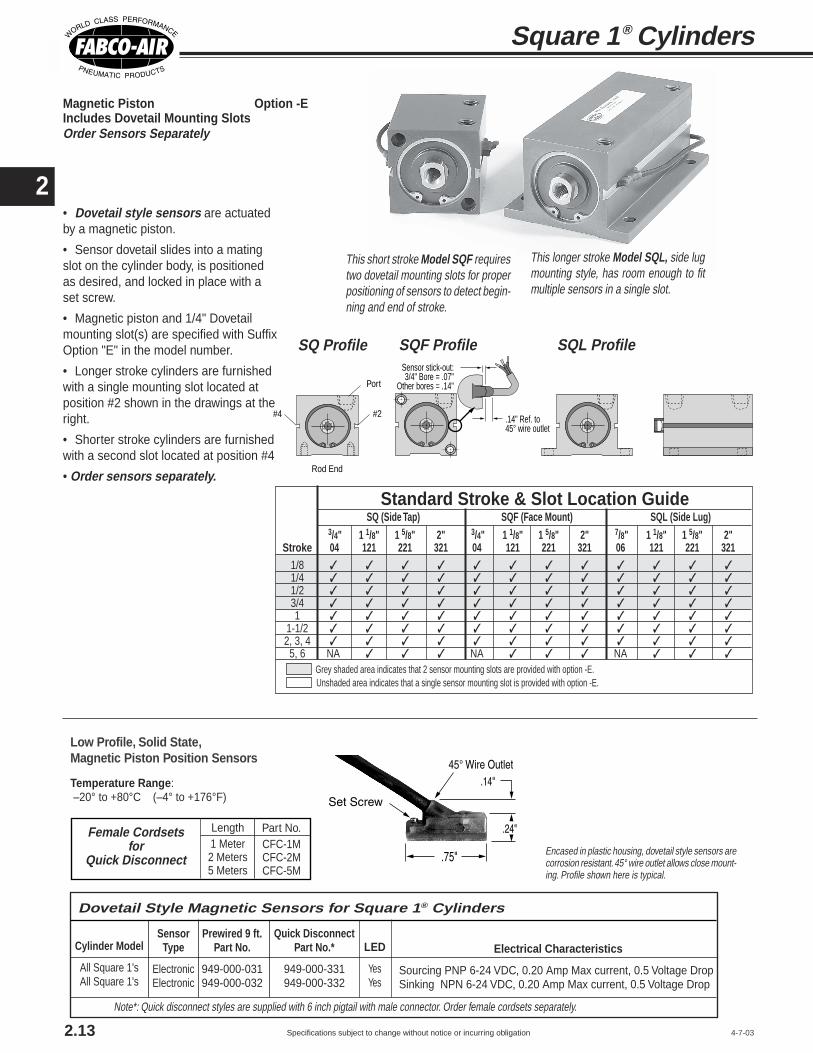
Specifications subject to change without notice or incurring obligation
2• Dovetail style sensors are actuatedby a magnetic piston.
• Sensor dovetail slides into a matingslot on the cylinder body, is positionedas desired, and locked in place with aset screw.
• Magnetic piston and 1/4" Dovetailmounting slot(s) are specified with SuffixOption "E" in the model number.
• Longer stroke cylinders are furnishedwith a single mounting slot located atposition #2 shown in the drawings at theright.
• Shorter stroke cylinders are furnishedwith a second slot located at position #4
• Order sensors separately.
Magnetic Piston Option -EIncludes Dovetail Mounting SlotsOrder Sensors Separately
Encased in plastic housing, dovetail style sensors arecorrosion resistant. 45° wire outlet allows close mount-ing. Profile shown here is typical.
Low Profile, Solid State,Magnetic Piston Position Sensors
Temperature Range: –20° to +80°C (–4° to +176°F)
This short stroke Model SQF requirestwo dovetail mounting slots for properpositioning of sensors to detect begin-ning and end of stroke.
This longer stroke Model SQL, side lugmounting style, has room enough to fitmultiple sensors in a single slot.
Standard Stroke & Slot Location GuideSQ (Side Tap) SQF (Face Mount) SQL (Side Lug)
3/4" 1 1/8" 1 5/8" 2" 3/4" 1 1/8" 1 5/8" 2" 7/8" 1 1/8" 1 5/8" 2"Stroke 04 121 221 321 04 121 221 321 06 121 221 321
1/8 ✓ ✓ ✓ ✓ ✓ ✓ ✓ ✓ ✓ ✓ ✓ ✓1/4 ✓ ✓ ✓ ✓ ✓ ✓ ✓ ✓ ✓ ✓ ✓ ✓1/2 ✓ ✓ ✓ ✓ ✓ ✓ ✓ ✓ ✓ ✓ ✓ ✓3/4 ✓ ✓ ✓ ✓ ✓ ✓ ✓ ✓ ✓ ✓ ✓ ✓1 ✓ ✓ ✓ ✓ ✓ ✓ ✓ ✓ ✓ ✓ ✓ ✓
1-1/2 ✓ ✓ ✓ ✓ ✓ ✓ ✓ ✓ ✓ ✓ ✓ ✓2, 3, 4 ✓ ✓ ✓ ✓ ✓ ✓ ✓ ✓ ✓ ✓ ✓ ✓
5, 6 NA ✓ ✓ ✓ NA ✓ ✓ ✓ NA ✓ ✓ ✓
Grey shaded area indicates that 2 sensor mounting slots are provided with option -E. Unshaded area indicates that a single sensor mounting slot is provided with option -E.
Sensor stick-out:3/4" Bore = .07"
Other bores = .14"
.14" Ref. to 45° wire outlet
Rod End
#2#4
Port
SQ Profile SQF Profile SQL Profile
Square 1® Cylinders
2.13
Note*: Quick disconnect styles are supplied with 6 inch pigtail with male connector. Order female cordsets separately.
Electrical Characteristics
Sourcing PNP 6-24 VDC, 0.20 Amp Max current, 0.5 Voltage DropSinking NPN 6-24 VDC, 0.20 Amp Max current, 0.5 Voltage Drop
Quick DisconnectPart No.*
949-000-331949-000-332
Prewired 9 ft.Part No.
949-000-031949-000-032
SensorType
ElectronicElectronic
LED
YesYes
Dovetail Style Magnetic Sensors for Square 1® Cylinders
Cylinder Model
All Square 1'sAll Square 1's
Length1 Meter2 Meters5 Meters
Part No.CFC-1MCFC-2MCFC-5M
Female Cordsetsfor
Quick Disconnect
4-7-03

Specifications subject to change without notice or incurring obligation
2
External Guide, Nonrotating Option -G
• Square guide pins are hard chrome platedsteel for long wear and corrosion resistance.• Guide blocks are hard anodized aluminumfor long wear and corrosion resistance.• Clearance in guide block mounting holesprovide for adjustment and backlash control,compensation for wear, and minimal rotation.• Extended distance between guides pro-vides superior nonrotation and support.• Extended piston rod provides clearancebetween cylinder and guide bar mountingblock to eliminate pinch points.
Superior nonrotating piston rod feature forapplications such as package placement,figure stamping, and any application whereanti-rotation and registration are critical asthe piston is extended and retracted.A mounting block is bolted to the pistonrod. This block has two square pinsmounted to it which in turn pass throughguide blocks mounted on the sides of thecylinder.
Option Specifications
2.147-26-01
E R
TF2
UF
A Sq. G†
Series SQF
F
FB4 Dia.4 Places
X
1B
1A1
2B
2A
3B3A
4B
42
3
4A
FB2 Dia.2 Places
TF4
Flange Mounting Kits for Series SQF and SQFW
Flange Style 7
Flange Style 8 & 9
Bore3/4"
1-1/8"1-5/8"
2"2"
A1.251.502.002.502.50
Kit #H7-04H7-121H7-221H8-321H9-321
Model04
121221321321
Style77789
E1.501.502.002.502.50
F.25.25.38.38.38
FBNANANA.38.28
FB2.22.22.22NANA
FB4.22.22.31NANA
G†.13.19.19.19.19
R1.001.001.431.842.00
TFNANANA3.383.00
TF21.752.002.50NANA
TF42.002.002.75NANA
UF2.502.503.384.133.50
W‡0.380.381.001.001.00
X.38.56.69.81.81
Port Positions1A Standard all models.To achieve 2A, 3A or 4A, rotate flange. For 1B, specify Option -1B For 2B, 3B, or 4B: Specify Option -1B
and rotate flange
Flange Bore Fabco Mounting Hole PatternStyle Size Kit No. Interchange Information
7 3/4" H7-04
7 1-1/8" H7-121
7 1-5/8" H7-221
8 2" H8-321
9 2" H9-321
4 Hole PatternC&C: 1-1/8" Bore, Series T, F, & RMosier: 1-1/8" Bore, Series TAV, 8 & 9PHD: 1-1/8" Bore, Series AV, RF, & CF2 Hole PatternCompact Air: 3/4" Bore, Style S, FF, & RF
4 Hole PatternC&C: 1-1/8" Bore, Series T, F, & RMosier: 1-1/8" Bore, Series TAV, 8 & 9PHD: 1-1/8" Bore, Series AV, RF, & CF2 Hole PatternCompact Air: 1-1/8" Bore, Style S, FF, & RF
4 Hole PatternNFPA Code MF1 & MF2 for 1-1/2" BoreAll brands conforming to this code2 Hole PatternCompact Air:1-5/8" Bore, Style S, FF, & RF
4 Hole PatternNFPA Code MF1 & MF2 for 2" BoreAll brands conforming to this code
4 Hole PatternCompact Air:2" Bore, Style S, FF, & RF
Kits include Flange and 2 Flange Mounting Screws
E R
TFUF
A Sq. W‡
Series SQFW
F
FB Dia.4 Places
X
1B
1A1
2B
2A
3B3A
4B
42
3
4A
SQFW-121-11/2with H7-121
Mounting Series SQ or SQFModel 04 121 221 321Bore 3/4" 1 1/8" 1 5/8" 2"AA 1.25 1.50 2.00 2.50BB .63 .69 .69 .69CC .63 .63 .63 .75DD 1.94 2.26 2.75 3.25EE .87 1.06 1.50 1.88FF 2.19 2.50 3.00 3.50GG .63 .63 .75 1.00HH 1.00 1.00 1.00 1.00JJ .19 .25 .25 .25
KK #6-32 #8-32 1/4-20 5/16-18
B + StrokeCCCC
BB
DD
DD__2
Mounting Block Clear Anodized Aluminum
JJ Square Guide PinsHard Chrome Plated Steel
Guide Block Hard Anodized Aluminum
AA SquareRef.
GG
HH
EE FFEE__2
Clearance in Guide BlockMounting Holes allow foradjustment to compensate for wear
KK Mounting Holes 2 Places
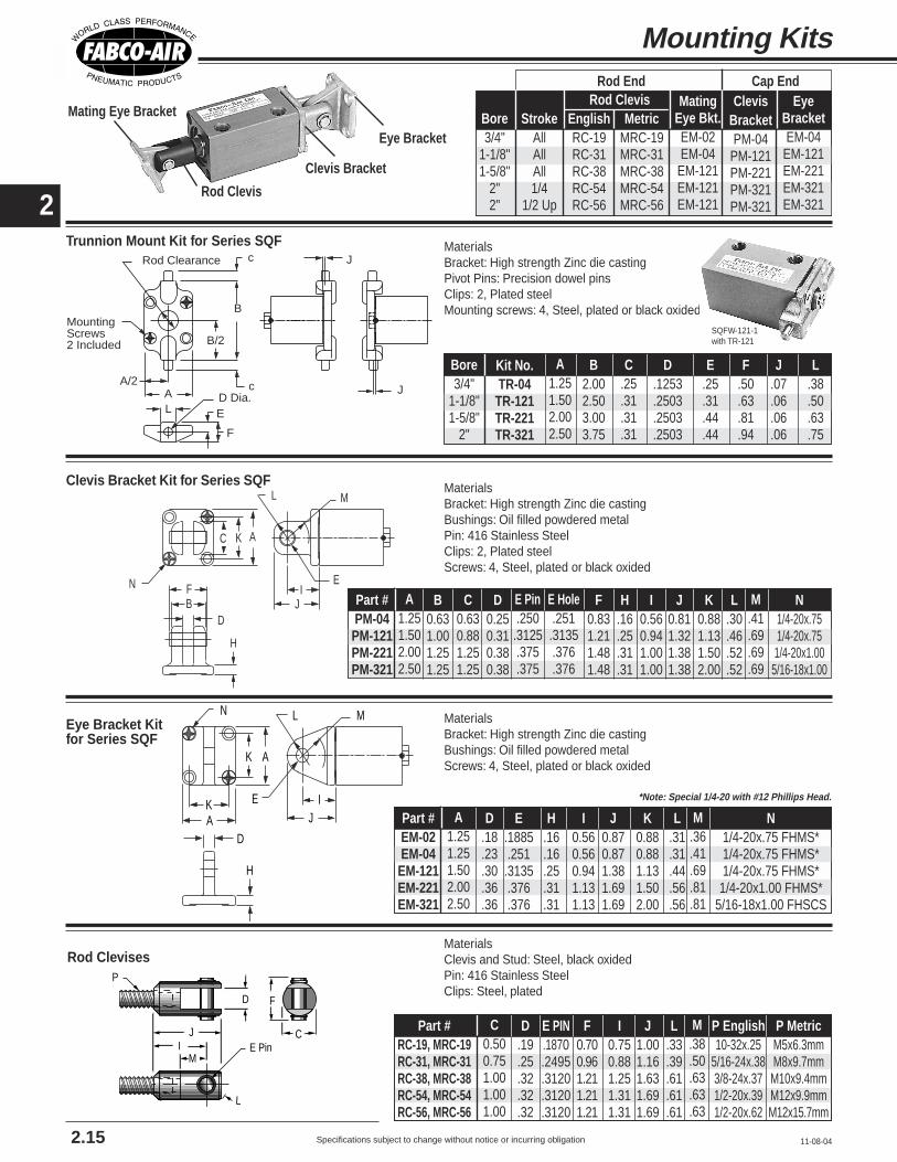
Specifications subject to change without notice or incurring obligation
2
Mounting Kits
Eye Bracket Kitfor Series SQF
Trunnion Mount Kit for Series SQFc
cA/2
B
B/2
AL E
F
D Dia.
MountingScrews2 Included
Rod Clearance J
J
N L M
IJ
H
AK
AK
E
D
C K A
IJ
E
ML
FB
N
D
H
Clevis Bracket Kit for Series SQF
Mating Eye Bracket
Rod Clevis
Clevis Bracket
Eye Bracket
Rod Clevises
MI
J
P
E PinC
D F
L
MaterialsClevis and Stud: Steel, black oxidedPin: 416 Stainless SteelClips: Steel, plated
MaterialsBracket: High strength Zinc die castingBushings: Oil filled powdered metalScrews: 4, Steel, plated or black oxided
MaterialsBracket: High strength Zinc die castingBushings: Oil filled powdered metalPin: 416 Stainless SteelClips: 2, Plated steelScrews: 4, Steel, plated or black oxided
MaterialsBracket: High strength Zinc die castingPivot Pins: Precision dowel pinsClips: 2, Plated steelMounting screws: 4, Steel, plated or black oxided
2.15 11-08-04
Kit No.TR-04
TR-121TR-221TR-321
A1.251.502.002.50
B2.002.503.003.75
C.25.31.31.31
D.1253.2503.2503.2503
E.25.31.44.44
F.50.63.81.94
J.07.06.06.06
L.38.50.63.75
Bore3/4"
1-1/8"1-5/8"
2"
StrokeAllAllAll1/4
1/2 Up
Bore3/4"
1-1/8"1-5/8"
2"2"
Rod ClevisEnglishRC-19RC-31RC-38RC-54RC-56
MetricMRC-19MRC-31MRC-38MRC-54MRC-56
Rod End Cap EndClevis
BracketPM-04
PM-121PM-221PM-321PM-321
MatingEye Bkt.EM-02EM-04
EM-121EM-121EM-121
EyeBracketEM-04
EM-121EM-221EM-321EM-321
C0.500.751.001.001.00
D.19.25.32.32.32
E PIN.1870.2495.3120.3120.3120
F0.700.961.211.211.21
I0.750.881.251.311.31
Part #RC-19, MRC-19RC-31, MRC-31RC-38, MRC-38RC-54, MRC-54RC-56, MRC-56
J1.001.161.631.691.69
L.33.39.61.61.61
M.38.50.63.63.63
P English10-32x.25
5/16-24x.383/8-24x.371/2-20x.391/2-20x.62
P MetricM5x6.3mmM8x9.7mm
M10x9.4mmM12x9.9mmM12x15.7mm
SQFW-121-1with TR-121
A1.251.251.502.002.50
D.18.23.30.36.36
E.1885.251.3135.376.376
H.16.16.25.31.31
I0.560.560.941.131.13
Part #EM-02EM-04EM-121EM-221EM-321
J0.870.871.381.691.69
K0.880.881.131.502.00
L.31.31.44.56.56
M.36.41.69.81.81
N1/4-20x.75 FHMS*1/4-20x.75 FHMS*1/4-20x.75 FHMS*1/4-20x1.00 FHMS*
5/16-18x1.00 FHSCS
*Note: Special 1/4-20 with #12 Phillips Head.
A1.251.502.002.50
B0.631.001.251.25
C0.630.881.251.25
D0.250.310.380.38
E Pin.250.3125.375.375
F0.831.211.481.48
H.16.25.31.31
I0.560.941.001.00
Part #PM-04PM-121PM-221PM-321
E Hole.251.3135.376.376
J0.811.321.381.38
K0.881.131.502.00
L.30.46.52.52
M.41.69.69.69
N1/4-20x.751/4-20x.751/4-20x1.00
5/16-18x1.00

Specifications subject to change without notice or incurring obligation
3
6-4-01
Page
Features & Benefits ..................................................................................... 3.2
General, Standard Ratings.......................................................................... 3.2
Construction Information ............................................................................. 3.3How a Longstroke™ is built
Model Number Chart ................................................................................... 3.4How to Order
Option List ................................................................................................... 3.4
Standard Specifications .............................................................................. 3.5 - 3.6
Option Specifications .................................................................................. 3.7 - 3.9Description of the Options
Mounting Kits .............................................................................................. 3.10
Accessories ................................................................................................. 3.10
Air Spring Return ........................................................................................ 1.15
Position Sensors ......................................................................................... 3.9
Directional Control Valves ........................................................................... Section 11
Port Mounted Flow Control Valves .............................................................. Section 12
Specials ....................................................................................................... ii & iii
2 Year Warranty ........................................................................................... Inside back cover
Round Head and Square Head Tie Rod Cylinders
S521-7-MR
521-7
3.1

Specifications subject to change without notice or incurring obligation
3
Bore Diameter 2" 2-1/2" 3" 4"Rod Diameter 0.75 0.75 0.75 0.88Rod Area 0.44 0.44 0.44 0.79Push Area (Single Rod) 3.14 4.91 7.07 12.57Pull Area 2.70 4.47 6.63 11.97Round Head Base Weight, lb. 2.21 2.83 3.66 5.98Square Head Weight, lb. 2.34 3.08 3.27 5.20Weight Per Inch, lb. 0.18 0.21 0.23 0.34
10-23-04
• Double acting, single rod• Duralon® rod bushing• Female rod end with wrench flats• Internally lubricated Buna-N O-ring
piston and rod seals.• Ports at position #1
• Media . . . . . . . . . . . . . . . . . . . . . . . . . . . . . . . . . . . . Air• Max. operating pressure . . . . . . . . . . . . . . . . . . 250 psi• Min. operating pressure recommended . . . . . . . 15 psi• Ambient & media temperature range . . -25° to +250°F• Prelubrication . . . . . . . . . . . . . . Magnalube®–G Grease• Stroke tolerance . . . . . . . . . . . . . . . . . . . . . . . . . ± 1/64"• Optional – Hydraulic . . . . . . . . . . . . 500 psi nonshock
Square Head Style
Round Head Style
Available in 2 styles4 Bore sizes 2" thru 4"Strokes to 12"
Longstroke™ Cylinders
Ratings – Standard Units all series
Sizing Guide
Piston Rod Bushing, hard anodizedaluminum housing with Teflon® linedDuralon® insert
Groove for magneticpiston position sensing
PTFE Bearing Strip is locatedaway from rod bearing formaximum load support
Load Capacity (psi)Machine Design 1972/73Bearing Reference Issue
Porous Bronze ............ 4,500Porous iron ................ 8,000Phenolics ................... 6,000Nylon® ....................... 1,000TFE ............................ 500Reinforced Telfon® .... 2,500*TFE fabric ................ 60,000Polycarbonate ............ 1,000Acetal ........................ 1,000Carbon-graphite ........ 600
* Shows Duralon bearing classification. Not to be used for design purposes.
Friction PropertiesSlip-
Coefficient stickSteel-on-steel ............... .50 YesBronze-on-steel ............. .35 YesSintered Bronze-on-steel with mineral oil ...... .13 NoBronze-on-steel with mineral oil ...... .16 NoCopper lead alloy-on-steel .22 YesAcetal-on-steel ............. .20 NoNylon-on-steel ............. .32 YesDuralon-on-steel .......... .05 - .16 No
Duralon® Rod Bearings Excel
Printed with permission by Rexnord Corp.
Piston Seal, internallylubricated O'Ring for long lifeand improved performance
3.2

Specifications subject to change without notice or incurring obligation
3
7-17-01
Longstroke™ Cylinders
Cylinder OD – is clear anodized aluminum for corrosionresistance and an attractive appearance.
The Bore ID is Hard Anodized – Hard anodizing isan electrochemical process which provides a very densesurface of aluminum oxide that actually impregnates thebase aluminum. It forms an extremely hard (60 Rc) sur-face with a low coefficient of friction. Hardness, corrosionresistance and wear resistance exceeds that of chromeplated steel.
An Extra Long Rod Bearing – provides long andrigid support for the piston rod. The bearing material isDuralon® on all bore sizes. See page 3 for a chart compar-ing the exceptional physical properties of Duralon® to othercommon, though less durable, bearing materials.
The Piston Rod – is Hard Chrome Plated StainlessSteel. The standard rod end is fine female thread tappedand has long wrench flats.
Standard ModelsStandard: Single Rod, Double Acting
Option -DR: Double Rod, see page 3.7
Option -K: Nonrotating, see page 3.8
1
3
8
6
21
20 19 7 9 2
16
3
12
4 4
16 10
18 17 11 13 15 14
5
1
3
8
6
21
20 19
16
3
18 15 14
225
12
26
24
23 17 11 13
7 9 16 10
Basic ConstructionQuick Reference to Components
No. Description
1 Rod End Head, aluminum, black anodized2 Cap End Head, aluminum, black anodized3 Recessed faces assure flat mounting4 1/4 NPT Ports5 Full flow porting for fast response6 Piston Rod Bushing, hard anodized aluminum
housing with Teflon® lined Duralon® insert7 Piston Stop8 Rod Seal, internally lubricated O'Ring for long life9 Piston Rod, stainless steel, centerless ground,
polished, and hard chrome plated (68-72Rc)10 Piston, aluminum11 Counter bore locates piston rod
to maintain precise concentricity12 Piston Bolt, steel, Loctited® and torqued13 Piston Seal, internally lubricated O'Ring for
long life and improved performance14 PTFE Bearing Strip is located away from rod
bearing for maximum load support15 Groove for magnet to activate position sensors16 O'Ring bumpers reduce metallic slap of piston on
piston stop for quiet operation17 Cylinder Tube, aluminum
Hard anodized ID (Rc60); Clear anodized OD18 Cylinder Tube end seal19 Stainless steel tie rods20 Stainless steel hex nuts21 Counterbore for nuts assures flat mounting22 Steel double rod stud, Loctited® and torqued23 Guide pin, precision ground tool steel24 Guide pin bushing, SAE 660 bearing bronze25 Guide pin seal, Urethane O'Ring26 Rubber disk prevents guide pin movement
1
3
8
6
21
20 19 7 9 10 2
16
3
22
54 4
18 17 11 13 15 14
6
89
16
3.3

Specifications subject to change without notice or incurring obligation
3
How to Order
How to Order
10--23-04
1. Specify Series–Bore2. Specify stroke
Note standard strokes listed above.Any stroke not listed is available,to 12" maximum, at nominal increasein delivery time and cost.
3. Specify mounting if other than standard4. Specify options
Examples321 - 8 - MRRound Head Longstroke, 2" bore, 8" stroke,Standard Mount – Face Mount on Rod End andCap End, Male Rod Thread
S721 - 7 - ESquare Head Longstroke, 3" bore, 7" stroke,Standard Mount – Side Tap Mount, Magnetic Piston
Description Specify See PageDouble Rod -DR 3.7Nonrotating, Square Head only -K 3.8
150 psi max. operating pressureMale Rod Thread 3.7
Single Rod -MRDouble Rod, Rod End -MRDouble Rod, Cap End -MR1Double Rod, Both Ends -MR2
Viton Seals (-15° to +400°F) -V 3.7Hydraulic, Low Pressure -H 3.7
to 500 psi NONSHOCKFinish, Pro-Coat™ ,
Electroless Nickle -N 3.8Rubber Bumpers 3.7
Rod End -BFCap End -BRBoth Ends -BFR
Adjustable Extend Stroke -AS 3.86" Stroke maximumFull stroke adjustment is standard
3/8 NPT Ports -P38 3.7Port Positions 3.5 & 3.6
All Ports Position #1 StandardPosition #2 -PA2Position #3 -PA3Position #4 -PA4
Rod End Position #1 StandardPosition #2 -PR2Position #3 -PR3Position #4 -PR4
Cap End Position #1 StandardPosition #2 -PC2Position #3 -PC3Position #4 -PC4
Any port not specified will be in Position #1as shown on page 3.5 & 3.6Magnetic Piston -E 3.9
for reed switches and Electronic Sensors(Order Sensors separately)
Options
Model Number Code– MR
MountingRod end face, round head only . . . . StandardCap end face, round head only . . . . StandardSide tap, square head only . . . . . . . StandardCap end clevis, round head only
Ports in line with slot . . . . . . . . . –PMPorts 90° to slot . . . . . . . . . . . . . –SM
Extended tie rodsRod end only . . . . . . . . . . . . . . . -WFCap end only . . . . . . . . . . . . . . . -WRRod & Cap end . . . . . . . . . . . . . -WFR
– 8321
Series
Round head
Square head
–
Mounting Kits for Square Head SeriesType See pageEnd Lug mount kit 3.10Side Lug mount kit 3.10
Specify
321521721
1221
S321S521S721
S1221
Bore
22-1/2"
3"4"
22-1/2"
3"4"
Mounting Kits for Round Head SeriesType See pageEye bracket kit 3.10Rod clevis 3.10
Stroke
Standard strokes:1" Increments
4" minimumthrough
12" maximum
Optional Strokes:Shorter and
fractional
3.4

Specifications subject to change without notice or incurring obligation
3
Longstroke™Cylinders
HA
1/2" Hex Nut30° 22.5° 21.5°
1
3.81 BC5.00 BC
32
41
3
2
4
1
32
43.25 BC
90° 1
3 2
2.81 BC
.33 Dia. .33 Dia. .33 Dia..33 Dia.
1.00
F Rod Dia.
3.38" + Stroke
0.25
0.50 0.501/4 NPT 1/4 NPT
1.00
K FemaleRod Thread
2" Bore 4" Bore3" Bore2-1/2" Bore
2.13" + Stroke
Rod End Cap End
Round Head, Standard, Face Mount Rod and Cap End
ZZ
BC
WF WR
BC
Rod End Cap End
2-1/2", 3", & 4" Bores4 Tie Rods
Equally Spaced
2" Bore3 Tie Rods
Equally Spaced
5/16-24 Thread
Dimensions
EE
0.25
JJ
FF-PM Port locations in line with slot
M
-SM Port locations 90° to slot
HH GG
3.38 + StrokeBB + Stroke
Round Head Clevis Mount OptionSpecify mounting option
Ports in line with slot -PMPorts 90° to slot -SM
Extended Tie Rod Mount for Round Head ModelsRod End Only - WFCap End Only -WRRod and Cap Ends -WFR
7-17-013.5
Bore2"
2-1/2"3"4"
A3.253.754.255.50
F Dia..750.750.750.875
H.63.63.63.75
E3.003.503.504.50
CNA1.751.752.25
EE1.251.631.632.00
FF.38.50.50.63
GG Pin.3745.4995.4995.6245
HH0.690.970.971.22
GG Hole.376.501.501.626
BB4.134.384.384.63
BC2.813.253.814.63

Specifications subject to change without notice or incurring obligation
3
1.00H
E
1/2Hex Nut
K FemaleThread
3.38"+ Stroke
0.25
0.50 0.50
1/4 NPT 1/4 NPT
1.00
C
E
Rod EndPort
0.81
TNTN
2.19
T
E
TH TH
NT NT
Cap EndPort 1
4
3
2
1
4
3
2
F Rod Dia.
N + Stroke
2.13"+ Stroke
2-1/2", 3", & 4" Bores2" Bore
Square Head, Standard, Side Tap Mount
WF WR
Rod EndPort
0.812.19
TH
Cap EndPort
BC BC
Rod End Cap End5/16-24 Thread
2-1/2", 3", & 4" Bores4 Tie Rods
Equally Spaced
2" Bore3 Tie Rods
Equally Spaced
Extended Tie Rod Mount for Square Head ModelsRod End Only - WFCap End Only -WRRod and Cap Ends -WFR
10-23-04
Dimensions
3.6
WR1.31.31.41.4
TN0.8751.2501.5002.060
WF1.31.31.41.4
NT5/16-18 x .623/8-16 x .751/2-13 x 1.001/2-13 x 1.00
TH1.3751.7501.7502.250
T.69.63.75.75
K1/2-20 x 1.001/2-20 x 1.001/2-20 x 1.005/8-18 x 1.25
JJ1.481.861.862.24
M.38.50.50.63
N2.252.382.132.13
Z60°30°
22.5°23.5°

Specifications subject to change without notice or incurring obligation
3
Longstroke™ Cylinders
7-2-01
Male Rod Thread OptionSingle Rod -MRDouble Rod, Rod End Only -MRDouble Rod, Cap End Only -MR1Double Rod, Rod & Cap Ends -MR2
A high strength stud is threadedinto the standard female rod endand retained with Loctite®. Thismethod eliminates the smalldiameter thread relief areanormally required when machin-ing male threads. This provides amuch stronger rod end which canbe repaired, rather than replacingthe complete rod, should thethread be damaged.
Double Rod Option -DRStandard piston rod and rodbushing on both ends of thecylinder.
Use when attachment to bothends of the cylinder is required, orto indicate piston position location.Also see Option –E on page 3.9.
Rubber Bumpers Option
Rod End only -BFCap End only -BRBoth Rod & Cap Ends -BFR
BORE THREAD2" 1/2–20 x 1.00
2 1/2" 1/2–20 x 1.003" 1/2–20 x 1.004" 5/8-18 x 1.25Thread
RodStud
Loctite®No ReliefNo Weakness
HydraulicLow Pressure Serviceto 500 psi non-shock Option -H
A U Cup rod seal is placed inboardin an SAE 660 bronze bushing toeliminate leakage past the rod seal.An additional O'ring is used as an out-board wiper.
Use with Air-Oil systems and lowpressure hydraulic systems when therigidity and precision smoothness ofhydraulics and control is required.
Viton Seals Option -V Use for elevated temperatures(–15° to + 400°F) or compatibility withexotic media.
Consult engineering for compatibilityinformation.
Rubber BumpersOption -BFR shown
Standard rubber mass will compress and givefull stoke at 60 to 80 psi. This mass can be ad-justed to meet your specific pressure and/or dy-namic load requirements.
A rubber doughnut is bonded to thecylinder head to act as the piston stopand absorb the impact of the piston. Thisreduces noise and absorbs energy, thusreducing destruction of the cylinder andtooling due to pounding. The amount ofrubber that extends beyond the normalpiston stop is designed to compress andallow full stroke of the cylinder at 60 to80 psi. If your application uses lowerpressure or has high energy, consultengineering with application details sothat rubber mass can be adjusted tomeet your specific requirements.
Because of the temperature limita-tions of the adhesives involved (-25° to
+ 220°F) Rubber Bumpers are availablein cylinders with standard internally lu-bricated Buna-N seals only.
Use to reduce noise and absorb im-pact.
Note! On applications such as punch-ing, shearing, setting blind rivets, etc.where high forces are built up and thenreleased very quickly, the proper methodof "CATCHING" this type of load is toadjust the cylinder piston and the tool-ing so that at the point of breakthroughthe piston is very close to the bumper.This reduces the dynamic load that thepiston and bumper are required to ab-sorb.
3.7
.25 + strokeTypical for ALLbores and ALLmounting styles.
Temperature Range (–25° to + 220°F)
3/8 NPT Ports Option -P38 Use 3/8 NPT ports for higher flows,air over oil systems, etc.

Specifications subject to change without notice or incurring obligation
3
10-23-04
Option Specifications
Adjustable extend strokeOption -AS
For strokes through 6"Full stroke adjustment is standard.
Note!To maintain operator safety featuresof this option, it is NOT available withmounting styles: -WR and -WFR.Use caution when mounting to avoidcreating pinch points.
Nut StopAdjustment Rod with fine pitch thread
(See Dimension “BF”)
Adjustment Nut with Mating Fine Pitch Thread
1/2"Minimum Clearance when fully stroked
Adjustment Nut SkirtLock ScrewPlastic Plug
Stop TubeRod Bushing
Contact Surfaces totally enclosed
Note: Use caution when mounting to avoid creating pinch points
+ (2 x Stroke)
+ Stroke
Bore 2" 2-1/2" 3" 4"
BA 1.50 1.50 1.50 2.00
BB 2.00 2.00 2.00 2.00
BC 1.65 1.65 1.65 1.42
BD 0.75 0.75 0.75 0.50
BE 0.75 0.75 0.75 0.75
BF .063 .063 .063 .063
BC + (2 x Stroke)
BD + StrokeBE + Stroke
BB Diameter
BFStroke adjustmentper revolution
BADiameter
Nonrotating Option -K150 psi Max. Operating Pressure
Square Head Series onlyin Single Rod andoptional Double Rod (-DR)
Two guide pins incorporated insidethe cylinder pass through the pistonhead. These guide pins prevent rotationof the rod with a tolerance of ±1°. Theguide pins, being incorporated inside,are protected from the environment,physical damage, and are lubricated bythe system lubrication, and require NOadditional space, leaving the rod endarea free for attachments and tooling asrequired by your application.
The guide pins are precision groundtool steel and run in SAE 660 bearingbronze bushings and PolyurethaneO'rings. These features provide preci-
WARNING
THIS CYLINDER HAS A NONROTATING ROD. TO PREVENT
INTERNAL DAMAGE HOLD ROD BY WRENCH FLATS WHEN
INSTALLING OR REMOVING ATTACHMENTS.
Guide Pin,Ground Tool Steel
Rubber Disk
Bushing, SAE 660 Bearing Bronze
O'Ring, Polyurethane
Wrench flat random rotation
sion guiding and long, trouble free life.A rubber disk is included at the end ofeach guide pin to take up end play andfirmly seat the pins in the precision guidepin holes.
An information label is applied to eachcylinder to warn against damage.
Use when any attachment to thepiston rod must not rotate.
FinishPlating; Pro-Coat™,Electroless Nickel,Heads & Tube Option -N
Pro-Coat™, Electroless Nickel Plat-ing is a hard, smooth, corrosion andwear resistant coating. It will often suf-fice for applications where stainlesssteel is specified. Its lasting luster pro-vides high eye appeal.
The coating is a high nickel, low phos-phorous alloy deposited by chemical re-duction without electric current that is"mil-for-mil" more corrosion resistantthan electroplated nickel. The surface isvirtually pore free. The thickness of thenickel deposit is constant over the en-tire surface. Blind holes, threads, small
diameter holes and internal surfaces allreceive the same amount of plating. Ithas natural lubricity and a high resis-tance to abrasion. As shipped hardnessof the coating is approximately 49Rockwell C. Heat treating can increasehardness to approximately 60 RockwellC. For specific applications, consult en-gineering.
The cylinder heads and tube, insideand outside, are plated. Tie rods andnuts are standard stainless steel. Rodbushing is standard hard anodized alu-minum and Duralon®.
3.8

Specifications subject to change without notice or incurring obligation
3
3.9 10-23-04
Suffix Option ESpecifies Magnetic Piston
(Order Sensors and Sensor Clamps Separately)
• Option -E consists of a magnet bonded into the piston head. Whenthe piston magnet moves past an external sensor, the magneticfield activates the sensor without physical contact.
• Mounting – The sensor snaps into a 2-part clamp that attachesrigidly to any of the tie rods and can be positioned anywhere alongthe length of the cylinder.
• Reliability – The annular piston magnet is permanently bondedinto a groove in the piston. It is a polarized permanent magnet ofrubber bonded barium ferrite that is very stable and is not affectedby shock. Under normal usage it will remain magnetized indefinitely.
• Warning – External magnetic fields and/or ferrous objects mayaffect the strength of the piston magnet therefore affecting sensoractuation and piston position indication. Warning labels (shown left)are affixed to the cylinder.
• Sensor clamps and sensors are ordered separately.
Sensor
Magnet, Rubber Bonded Barium Ferrite
Tie Rod, Stainless
Steel
Cylinder HeadCylinder Tube
Piston Rod
Piston
Clamp
T
T
Sensor
Magnet, Rubber Bonded Barium Ferrite
Tie Rod, Stainless
Steel
Cylinder Head
Cylinder Tube
Piston Rod
Piston
Clamp
T
Model 521 – 6 – E shown with2 prewired electronic sensors
Female Cordsets availablein 1, 2, & 5 meter lengths
9 foot prewired sensor
2-Piece Sensor Clamp shownwith quick disconnect sensor
snapped in place
Socket Head ScrewQuick DisconnectSensor Shown
WARNINGThis cylinder is equipped with a MagneticPiston for use with Magnetically OperatedSensors. Other Magnetic Sensitive De-vices Should be Kept at a Distance to AvoidInadvertent Operation.
Sensor & Clamp Ordering Guide
Electrical Characteristics
5-120 VDC/VAC, 0.5 Amp Max., 10 Watt Max., SPST N.O., 3.5 Voltage DropSourcing, PNP, 6-24 VDC, 0.5 Amp Max., 1.0 Voltage DropSinking, NPN, 6-24VDC, 0.5 Amp Max., 1.0 Voltage Drop
Quick DisconnectPart Number.
9-2A197-13049-2A197-13339-2A197-1334
Prewired9 ft. Part No.
9-2A197-10049-2A197-10339-2A197-1034
ProductType
Reed SwitchElectronicElectronic
LED Lighted Magnetic Piston Position Sensors
For all Longstroke Models Order Part Number 800-200-000
Length 1 Meter 2 Meter 5 Meter
Part Number CFC-1M CFC-2M CFC-5M
Sensor Mounting Clamp - for all Longstroke Models
Female Cordsets for Quick Disconnect
Warning!
Do not exceed sensor ratings.Permanent damage to sensormay occur.
Power supply polarity MUSTbe observed for proper opera-tion of sensors.
See wiring diagrams includedwith each sensor.
Top View Round Head Style Top View Square Head Style
Model 321 S321 521 S521 721 S721 1221 S1221
T .50" .50" .50" .10" .50" .30 .30" .30"
Sensor Clamp Stick Out Dimensions
Temperature Range: –20° to + 80°C (–4° to + 176°F)
Longstroke™ Cylinders

Specifications subject to change without notice or incurring obligation
3
3.10
Kit includes:2 brackets and 4 bolts forattaching the brackets tothe cylinder heads.
Material:Brackets, plated steelScrews, Black Oxide Steel
Mounting Kits & Accessories
10-23-04
Eye Bracket Kits mate with Option -PM or -SM and Rod ClevisN L M
IJ
H
DB
C
AK
E
MaterialsBracket: High strength Zinc die castingBushings: Oil filled powdered metalScrews: 4, Steel, plated or black oxided
Rod Clevises
MI
J
P
E PinC
D F
L
MaterialsClevis and Stud: Steel, black oxidedPin: 416 Stainless SteelClips: Steel, plated
C1.001.38
D.32.50
E PIN.3120.4995
F1.211.62
I1.311.63
Part #RC-56RC-63
J1.692.13
L.61.80
M.63.94
P1/2-20x.625/8-18x.75
Mating Eye BktEM-121EM-521
Bore2", 2-1/2", & 3"
4"
Side Lug Mount Kit
End Lug Mount Kit
AB.41.41.53.53
AH1.632.002.132.63
AO.44.44.56.56
AT.25.25.38.38
SA3.753.884.384.38
XA3.693.754.004.00
Bore2"
2-1/2"3"4"
S1.752.252.753.50
W2.503.003.504.50
Kit No.EL-20EL-25EL-30EL-40
XA + Stroke AB 6 HolesAH
AOAT SA + Stroke AO
SW1
4
2
W/2 S/23
XE1 + StrokeLH
EO1 SS1 + Stroke
TSUS
1
4
2
US/2 TS/2
3
EO1
SB 4 Holes
ST
XE2 + Stroke
LH
EO2 SS2 + Stroke
TSUS
1
4
2
US/2 TS/2
3
EO2
SB 4 Holes
ST
Position #1 Position #2
Kit includes:2 brackets and 4 bolts forattaching the brackets tothe cylinder heads.
Material:Brackets, plated steelScrews, Black Oxide Steel
EO10.500.500.560.56
SS12.382.633.253.25
SS22.132.131.001.00
ST.25.25.38.38
TS3.754.254.755.50
Bore2"
2-1/2"3"4"
LH1.632.002.132.63
SB.41.41.53.53
Kit No.SL-20SL-25SL-30SL-40
EO20.500.631.191.19
A2.502.002.501.50
D.36.47.58.30
E.376.501.626.3135
H.31.38.38.25
I1.131.501.630.94
Part #EM-321EM-521EM-1221EM-121
J1.692.252.631.38
K2.001.381.751.13
L0.560.751.000.44
M0.811.131.100.69
Bore2"
2-1/2", 3"4"
Rod Clevis RC-56
B2.502.002.251.50
C2.001.381.501.13
N5/16-18x1.00FHSCS5/16-18x1.00FHSCS5/16-18x1.00FHSCS
1/4-20X.75 FH(#12)MS
US4.505.005.886.63
XE13.003.133.443.44
XE22.882.882.312.31

Specifications subject to change without notice or incurring obligation
4
5
3-24-03
Hi-Power™ Series – PageConstruction & engineering data . . 4.2 & 4.3How to Order . . . . . . . . . . . . . . . . . . . . . . 4.4Dimensions . . . . . . . . . . . . . . . . . . 4.5 & 4.6Option Specifications . . . . . . . . . . 4.7 - 4.10
Multi-Power® Series –Construction & engineering data . . . 5.1 - 5.3Sizing Guide . . . . . . . . . . . . . . . . . . . . . . 5.2How to Order . . . . . . . . . . . . . . . . . . . . . . 5.4Dimensions . . . . . . . . . . . . . . . . . . 5.5 & 5.6Option Specifications . . . . . . . . . . 5.7 - 5.12
Pancake® Multi-Power® Series –Sizing Guide . . . . . . . . . . . . . . . . . . . . . 5.13How to Order . . . . . . . . . . . . . . . . . . . . . 5.14Dimensions . . . . . . . . . . . . . . . . 5.13 & 5.14
Square1® Multi-Power® Series –Sizing Guide . . . . . . . . . . . . . . . . . . . . . 5.15How to Order . . . . . . . . . . . . . . . . . . . . . 5.15Dimensions . . . . . . . . . . . . . . . . . . . . . . 5.16
Longstroke™ Multi-Power® Series –Sizing Guide . . . . . . . . . . . . . . . . . . . . . 5.17How to Order . . . . . . . . . . . . . . . . . . . . . 5.17Dimensions . . . . . . . . . . . . . . . . . . . . . . 5.18
Product Index
4.1
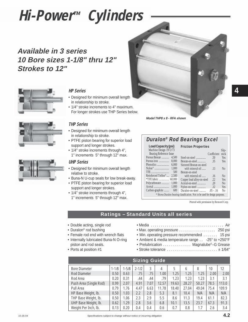
Specifications subject to change without notice or incurring obligation
4
5
HP Series• Designed for minimum overall length
in relationship to stroke.• 1/4" stroke increments to 4" maximum.
For longer strokes use THP Series below.
THP Series• Designed for minimum overall length
in relationship to stroke.• PTFE piston bearing for superior load
support and longer strokes.• 1/4" stroke increments through 4",
1" increments 5" through 12" max.
UHP Series• Designed for minimum overall length
relative to stroke.• Buna-N U-cup seals for low break-away.• PTFE piston bearing for superior load
support and longer strokes.• 1/4" stroke increments through 4",
1" increments 5" through 12" max.
Bore Diameter 1-1/8 1-5/8 2-1/2 3 4 5 6 8 10 12Rod Diameter 0.50 0.63 .75 .75 1.00 1.25 1.25 1.25 2.00 2.00Rod Area 0.20 0.31 .44 .44 .79 1.23 1.23 1.23 3.1 3.1Push Area (Single Rod) 0.99 2.07 4.91 7.07 12.57 19.63 28.27 50.27 78.5 113.0Pull Area 0.79 1.76 4.47 6.63 11.78 18.40 27.04 49.04 75.4 109.9HP Base Weight, lb. 0.50 1.03 2.2 2.8 5.3 8.1 10.4 N/A N/A N/ATHP Base Weight, lb. 0.50 1.06 2.3 2.9 5.5 8.6 11.3 19.4 61.1 82.3UHP Base Weight, lb. 0.62 1.29 2.8 3.6 6.8 10.1 13.5 23.7 67.3 91.3Weight Per Inch, lb. 0.13 0.20 0.4 0.4 0.6 0.7 0.8 1.7 2.6 3.4
10-26-04
Available in 3 series10 Bore sizes 1-1/8" thru 12"Strokes to 12"
• Double acting, single rod• Duralon® rod bushing• Female rod end with wrench flats• Internally lubricated Buna-N O-ring
piston and rod seals.• Ports at position #1
• Media . . . . . . . . . . . . . . . . . . . . . . . . . . . . . . . . . . . . Air• Max. operating pressure . . . . . . . . . . . . . . . . . . 250 psi• Min. operating pressure recommended . . . . . . . 15 psi• Ambient & media temperature range . . -25° to +250°F• Prelubrication . . . . . . . . . . . . . . Magnalube®–G Grease• Stroke tolerance . . . . . . . . . . . . . . . . . . . . . . . . . ± 1/64"
Load Capacity (psi)Machine Design 1972/73Bearing Reference Issue
Porous Bronze ............ 4,500Porous iron ................ 8,000Phenolics ................... 6,000Nylon® ....................... 1,000TFE ............................ 500Reinforced Telfon® .... 2,500*TFE fabric ................ 60,000Polycarbonate ............ 1,000Acetal ........................ 1,000Carbon-graphite ........ 600
* Shows Duralon bearing classification. Not to be used for design purposes.
Friction PropertiesSlip-
Coefficient stickSteel-on-steel ............... .50 YesBronze-on-steel ............. .35 YesSintered Bronze-on-steel with mineral oil ...... .13 NoBronze-on-steel with mineral oil ...... .16 NoCopper lead alloy-on-steel .22 YesAcetal-on-steel ............. .20 NoNylon-on-steel ............. .32 YesDuralon-on-steel .......... .05 - .16 No
Duralon® Rod Bearings Excel
Printed with permission by Rexnord Corp.
Hi-Power™ Cylinders
Model THP8 x 8 - RFA shown
Ratings – Standard Units all series
Sizing Guide
4.2

Specifications subject to change without notice or incurring obligation
4
5
Hi-Power™ Cylinders
Cylinder OD – is clear anodized aluminum for corrosionresistance and an attractive appearance.
The Bore ID is Hard Anodized – Hard anodizing isan electrochemical process which provides a very densesurface of aluminum oxide that actually impregnates thebase aluminum. It forms an extremely hard (60 Rc) sur-face with a low coefficient of friction. Hardness, corrosionresistance and wear resistance exceeds that of chromeplated steel.
An Extra Long Rod Bearing – provides long andrigid support for the piston rod. The bearing material isDuralon® on all bore sizes. See page 4.2 for a chart com-paring the exceptional physical properties of Duralon® toother common, though less durable, bearing materials.
The Piston Rod – is Hard Chrome Plated StainlessSteel. The standard rod end is fine female thread tappedand has long wrench flats.
Piston Construction – The piston is aluminum for lightweight. The piston rod pilot end and a pilot washer enablebolting the assembly securely while maintaining preciseconcentricity for smooth cylinder performance.
3 15 14 344
6
7 16
7
12
5
2
11
10 13
8
1
9
3 15 14 344
6
7 16
7
12
5
2
11
10 13 17
8
1
9
3 15 14 34
4
6
7 16
7
12
5
2
11
10 18 19
8
1
9
17 18
Basic ConstructionStandard Models
THP Series
UHP Series
HP SeriesQuick Reference to Components
No. Description
1 Rod End Head, aluminum, black anodized2 Cap End Head, aluminum, black anodized3 NPT Ports4 Full flow porting for fast response5 Cap End Plug, aluminum, black anodized6 Piston Rod Bushing, anodized aluminum
housing with Teflon® lined Duralon® insert7 Piston Stop8 Rod Seal, internally lubricated O'Ring for long life9 Piston Rod, stainless steel, centerless ground,
polished, and hard chrome plated (68-72Rc)10 Piston, aluminum11 Piston Rod Pilot Washer locates piston
to maintain precise concentricity12 Piston Bolt, steel, Loctite® applied and torqued13 Piston Seal, internally lubricated O'Ring for
long life and improved performance14 Cylinder Tube, aluminum
Hard anodized ID (Rc60); Clear anodized OD15 Cylinder Tube Seal16 Stainless steel tie rods and plated steel nuts17 PTFE Piston Bearing for superior load support18 U Cup Seals, Buna-N19 Magnet for piston position sensors
12-15-044.3

Specifications subject to change without notice or incurring obligation
4
5
How to Order
12-15-04
Description Specify See PageDouble Rod -DR 4.10
HP: 1-1/8" thru 6" BoreTHP: 8" thru 12" BoreUHP: 1-1/8" thru 12" Bore
Hole Thru Double Rod Shaft 4.10150 psi max. operating pressureBore Hole1-1/8", 1-5/8" .13" -DR132-1/2", 3" .16" -DR164", 5", 6" .25" -DR258", 10", 12" Not available
Nonrotating -K 4.10150 psi max. operating pressureHP: 1-5/8" Bore & Larger
THP: All BoresUHP: 2-1/2" Bore & Larger
Male Rod Thread 4.7Single Rod -MRDouble Rod, Rod End -MRDouble Rod, Cap End -MR1Double Rod, Both Ends -MR2
Viton Seals (-15° to +400°F) -V 4.7Hydraulic, Low Pressure -H 4.10
to 500 psi NONSHOCK (HP & THP Only)Rubber Bumpers 4.8
Rod End -BFCap End -BRBoth Ends -BFR
Adjustable Extend Stroke -AS 4.76" Stroke MaximumFull stroke adjustmentis standard.
1/2 NPT Ports in Heads ‡ 4.8(2-1/2", 3", 4", 5", & 6" Bores only)Rod End Head -TFCap End Head -TRBoth Heads -TFR
3/4 NPT Ports in Heads 4.810" & 12" Bores only -P34
Extend Port Bushing 4.83/8 NPT (2-1/2" – 6" Bores) -E381/2 NPT (2-1/2" – 6" Bores) -E123/4 NPT (5" – 12" Bores) -E34
Port Positions 4.5 & 4.6All Ports • Position #1 Standard #2 -PA2; #3 -PA3; #4 -PA4Rod End Port •Position #1 Standard #2 -PR2; #3 -PR3; #4 -PR4Cap End Port •Position #1 Standard #2 -PC2; #3 -PC3; #4 -PC4Any port not specified will be in position #1as shown on pages 4.5 & 4.6
Magnetic Piston ‡ -E 4.9for Reed Switches and ElectronicSensors (Order Sensors separately)
‡ Note: Additional Cylinder Length Requiredfor 1/2 NPT Ports Option see page 4.8;for Option -E see page 4.9.
Model Number Code
x –3 3 FFHP
How to Order1. Specify Series and Bore2. Specify Stroke in Inches and Fractions3. Specify Mounting4. Specify Options
ExamplesHP3 x 3 FF – MRHP Series Hi-Power™, 3" bore, 3" stroke, Front Face(Fabco Pattern) Mount, Male Rod Thread
THP5 x 7 – RFA – TFRPTFE Piston Bearing Series, 5" Bore, 7" Stroke,Rear Face [NFPA MF2 pattern] Mount,1/2 NPT Ports in Rod and Cap Heads
OPTIONS
– MR
Bores MountingSeries HP, Front Face – Fabco Pattern . . . . . . . . . . –FFTHP, and Front Face – NFPA (MF1) Pattern . . . . –FFA
UHP Rear Face – Fabco Pattern . . . . . . . . . . –RF1-1/8" Rear Face – NFPA (MF2) Pattern . . . . –RFA
through Foot . . . . . . . . . . . . . . . . . . . . . . . . . . . . –FT6" Clevis Mount – NFPA (MP1) Dimensions
Ports in-line with slot . . . . . . . . . . . . -PMPorts 90° to slot . . . . . . . . . . . . . . . . -SM
Extended Tie RodsRod end only . . . . . . . . . . . . . . . . . –WFCap end only . . . . . . . . . . . . . . . . . –WRRod and Cap Ends . . . . . . . . . . . –WFR
Series THP Front Face – NFPA (ME3) Pattern . . . . –FFAand Rear Face – NFPA (ME4) Pattern . . . . –RFA
UHP only Extended Tie Rods8" Rod end only . . . . . . . . . . . . . . . . . –WF
10" Cap end only . . . . . . . . . . . . . . . . . –WR12" Rod and Cap Ends . . . . . . . . . . . –WFR
SeriesHP
THPUHP
Standard Strokes
1/4" Stroke Incrementsthrough 4" (maximum)
Bores1 1/8"1 5/8"
2"
1/4" Stroke Incrementsthrough 4"
1" Stroke Incrementsthrough 12" (maximum)
Bore1-1/81-5/82-1/2
3456
1-1/81-5/82-1/2
345681012
4.4

Specifications subject to change without notice or incurring obligation
4
5
3-22-03
Hi-Power™ Cylinders
-RF Rear Face Mount; Cap End Rectangular FlangeFabco mounting pattern
T T
RRA
GH
MJ
U
AOThd
NHex Nut4 PlacesRod End
Q1
2
3
4
LS
E
K
S
C
E
BD
F
-FF Front Face Mount; Rod End Rectangular FlangeFabco mounting pattern
1-1/8", 1-5/8", 2-1/2", 3", 4", 5", & 6" Bores
-RFA Rear Face Mount; Cap End Rectangular FlangeNFPA (MF2) mounting pattern
T T
RRA
G
H
MJ
NHex Nut4 PlacesRod End
U
AOThd
Q 1
2
3
4
LS
E
K
S
CCE
BBDD
FF
FABCO 1-5/8" = NFPA 1-1/2"FABCO 3" = NFPA 3-1/4"
-FFA Front Face Mount; Rod End Rectangular FlangeNFPA (MF1) mounting pattern
T T
RRA
GH
MJ
U
NHex Nut4 PlacesCap End
AOThd
Q1
2
3
4
LS
E
K
CC
S
E
BBDD
FF
FABCO 1-5/8" = NFPA 1-1/2"FABCO 3" = NFPA 3-1/4"
ABore1-1/81-5/82-1/2
345681012
B2.002.503.633.885.006.007.007.579.4011.10
Series HP1.31 + stroke1.75 + stroke2.06 + stroke2.06 + stroke2.06 + stroke2.50 + stroke2.38 + stroke
NANANA
Series THP1.50+stroke2.00+stroke2.25+stroke2.25+stroke2.25+stroke2.75+stroke2.75+stroke2.88+stroke4.75+stroke4.75+stroke
Series UHP2.63+stroke3.00+stroke3.25+stroke3.25+stroke3.25+stroke3.50+stroke3.50+stroke3.75+stroke5.75+stroke5.75+stroke
Dimensions (inches)
C1.251.752.382.753.754.505.25NANANA
D2.503.004.254.506.007.008.00NANANA
E1.752.253.003.505.006.007.009.0012.0014.00
F.28.28.34.34.41.53.53.69.78.78
G.13.13.19.19.19.19.19.13.25.25
H.50.50.50.50.50.69.69.631.001.00
J±.002 .7521.0011.1271.1271.5021.7521.7521.7522.7512.751
±.001 .500.625.750.7501.0001.2501.2501.2502.0002.000
MK
5/16-24x.633/8-24x.631/2-20x.751/2-20x.751/2-20x.753/4-16x1.133/4-16x1.133/4-16x1.1311/2-12x1.7511/2-12x1.75
L7/161/25/85/87/8111
1.751.75
N7/167/169/169/163/43/43/43/4
1-1/81-1/8
P2.382.883.694.135.506.253.38NANANA
NPT1/81/81/41/41/41/41/43/81/21/2
QR
.50
.63
.75
.75
.75
.75
.751.001.501.50
T T
RRA
GH
MJ
URF
FL
CD Pin
ERLR
CW CWCB
ECL
Cross Pin andClips Included
N Hex Nut 4 Places Both Ends 2-1/2" thru 6" Bores;Rod end only 1-1/8" & 1-5/8" Bores
Fabco 1-1/8" = NFPA 1-1/2"Fabco 1-5/8" = NFPA 1-1/2"Fabco 3" = NFPA 3-1/4"
Material: Gray Iron Casting,Black Oxide Finish
Clevis Mount (NFPA MP1 Dimensions)-PM - Ports in-line with slot-SM -Ports 90° to slot
4.5
T T
RRA
GH
MJ
UAOThd
NHex Nut4 PlacesCap End
Q1
2
3
4
LS E
K
S
C
E
BD
F

Specifications subject to change without notice or incurring obligation
4
5
Bore1-1/81-5/82-1/2
345681012
S1.191.622.312.693.504.255.137.9010.6312.46
Dimensions (inches)
T.22.25.31.31.31.31.31.44.75.75
U.27.27.38.38.50.50.50.50.80.80
V.22.22.33.33.43.43.43.43.66.66
X.31.38.44.50.63.75.75NANANA
BB2.002.753.884.695.446.637.63NANANA
Z.44.63.56.75.88
1.001.00NANANA
AO1/4-201/4-203/8-163/8-161/2-131/2-131/2-131/2-133/4-103/4-10
WNANANANANANANA4.565.005.81
CC1.001.432.192.763.324.104.88NANANA
DD2.503.254.505.316.387.638.63NANANA
FF.22.28.34.41.41.53.53NANANA
FO3.003.504.384.886.387.257.00NANANA
HC1.131.381.752.002.753.253.75NANANA
HT2.002.503.253.755.256.257.25NANANA
WF1.01.01.31.41.41.81.82.32.682.68
WR1.01.01.31.41.41.81.82.3
2.682.68
CD.500.500.500.750.750.7501.000NANANA
FL.75.75.751.251.251.251.50NANANA
RF.38.38.38.63.63.63.75NANANA
CB.76.76.76
1.261.261.261.51NANANA
CW.50.50.50.62.62.62.75NANANA
ER.62.62.62.87.87.871.25NANANA
LR.62.62.62.87.87.87
1.13NANANA
CL2.092.092.092.882.882.883.38NANANA
10-26-04
To OrderExtended Tie Rod Mount
Specify SuffixRod End only –WFCap End only –WRRod & Cap Ends –WFR
-FT Foot Mount
XX
T T
RR
A
GH
MJ
NHex Nut4 PlacesBoth Ends
.25Z Z
Q 1
2
3
4
LS
P
K
S
FO
HT
HC
E
F
-WF Extended Tie Rod Mount, Rod End Only-WR Cap End Only-WFR Rod & Cap Ends
VV
T T
RR
A
GH
MJ NHex Nut4 PlacesBoth EndsALLModels
WF WR
AOThd
Q1
2
3
4
LS
E
K
SE
1-1/8", 1-5/8", 2-1/2", 3", 4", 5", & 6" Bores
If a non-standard extensionis required, specify by add-ing the required length tothe suffix.e.g. If –WF length requiredis 2.5", Specify –WF2.5"
▼
8", 10", and 12" Bores
-FFA Front Face Mount; Rod End Square FlangeNFPA (ME3) mounting pattern
QRod End View 1
2
3
4
WBS
E
AO Thd
F
U
T T
RRA
GH
MJ
K
NHex Nut8 PlacesCap End
L
-WF Extended Tie Rod Mount, Rod End Only-WR Cap End Only-WFR Rod & Cap Ends
Q1
2
3
4
WL
SE
K
V
T T
RRA
GH
MJNHex Nut8 PlacesBoth Ends
WF WR
AOThd
-RFA Rear Face Mount; Cap End Square FlangeNFPA (ME4) mounting pattern
UT T Q Cap End View1
2
3
4
WB
SE
AOThd
FRR
AG
H
MJ
K TapL Flats
NHex Nut8 PlacesRod End
▼
Mounting Styles with Dimensions
4.6

Specifications subject to change without notice or incurring obligation
4
5
3-21-03
ADJUSTABLE EXTEND STROKEFor strokes through 6" -ASFull stroke adjustment is standard.Note!To maintain operator safety featuresof this option, it is NOT available withmounting styles: -WR and -WFR.Use caution when mounting to avoidcreating pinch points.Not available for 10" & 12" bores
Dial-A-Stroke® provides a rugged andprecision adjustment of the extend strokeof the cylinder. The stop tube, adjustmentnut with skirt, and minimum clearancescombine to eliminate pinch points, thusproviding operator safety. Note! Usecaution when mounting to avoid creatingpinch points with other parts of yourmachine design.
The stop tube is blue anodizedaluminum, the adjustment nut is black-ened steel with a black anodizedaluminum skirt, and the nut stop is redanodized aluminum; all for corrosionresistance and appearance. The adjust-ment nut, steel for long life, includes alock screw with a plastic plug so that theadjustment nut can be locked in placewithout damaging the threads. The nutstop is mounted on the end of theadjustment rod so that the nut cannotcome off. The fine pitch threads on theadjustment rod and nut provide precisionadjustment. (See dimension "BF").Adjustment settings are simplified byconvenient scale markings applied to nutskirt and stop tube.
Nut StopAdjustment Rod with fine pitch thread
(See Dimension “BF”)
Adjustment Nut with Mating Fine Pitch Thread
1/2"Minimum Clearance when fully stroked
Adjustment Nut SkirtLock ScrewPlastic Plug
Stop TubeRod Bushing
Contact Surfaces totally enclosed
Note: Use caution when mounting to avoid creating pinch points
OPTIONVITON SEALS -V
MALE ROD THREADSingle Rod -MRDouble Rod, Rod End Only -MRDouble Rod, Cap End Only -MR1Double Rod, Rod & Cap Ends -MR2
Use for elevated temperatures (–15° to + 400°F) orcompatibility with exotic media. Consult engineering forcompatibility information.
For bores 1-1/8" thru 8", a highstrength stud is threaded into thestandard female rod end and retainedwith Loctite®. This method eliminatesthe small diameter thread relief areanormally required when machining male
BORE THREAD1-1/8" . . . . 5/16–24 x .631-5/8" . . . . 3/8–24 x .882-1/2" . . . . 1/2–20 x 1.00
3" . . . . . . 1/2–20 x 1.004" . . . . . . 1/2–20 x 1.005" . . . . . . 3/4–16 x 1.506" . . . . . . 3/4–16 x 1.508" . . . . . . 3/4–16 x 1.5010" . . . . 1-1/2–12 x 2.2512" . . . . 1-1/2–12 x 2.25
threads. This provides a much stronger rodend which can be repaired, rather thanreplacing the complete rod, should thethread be damaged. For 10" and 12", thethread is machined integral with the rod.
Thread
BC + (2 x Stroke)
BD + StrokeBE + Stroke
BB Diameter
BFStroke adjustmentper revolution
BADiameter
Bore 1-1/8" 1-5/8" 2-1/2" 3" 4" 5" 6" 8"
BA 1.13 1.25 1.50 1.50 2.00 2.25 2.25 2.25
BB 1.50 1.50 2.00 2.00 2.00 2.25 2.25 2.25
BC 1.67 1.67 1.90 1.90 1.67 1.67 1.67 1.67
BD 1.00 1.00 1.00 1.00 .75 .75 .75 .75
BE .50 .50 .75 .75 .75 .75 .75 .75
BF .050 .050 .063 .063 .063 .071 .071 .071
+ (2 x Stroke)
+ Stroke
Hi-Power™ Cylinders
Rod
Loctite®
Stud
No ReliefNo Weakness
4.7

Specifications subject to change without notice or incurring obligation
4
5
1-19-07
Option Specifications
RUBBER BUMPERSRod End only -BFCap End only -BRBoth Rod & Cap Ends -BFR
A rubber doughnut is bonded to thecylinder head to act as the piston stopand absorb the impact of the piston.This reduces noise and absorbs energy,thus reducing damage to the cylinderand tooling due to pounding. Theamount of rubber that extends beyondthe normal piston stop is designed tocompress and allow full stroke of thecylinder at 60 to 80 psi. If your applica-tion uses lower pressure or has highenergy, consult engineering with appli-cation details so that rubber mass canbe adjusted to meet your specific re-quirements.
Because of the temperature limitationsof the adhesives involved (-25° to +225°F),rubber bumpers are available in cylinderswith standard internally lubricated Buna-N seals only.
Use where noise reduction and im-pact absorption is desired.
Note! On applications such as punch-ing, shearing, setting blind rivets, etc.,where high forces are built up and thenreleased VERY quickly, the proper methodof “catching” this type of load is to adjustthe cylinder piston and the tooling so thatat the point of breakthrough the piston isvery close to the bumper. This reduces thedynamic load that the piston and bumperare required to absorb.
Rubber Bumpers
EXTEND PORT BUSHING OPTION3/8 NPT (2-1/2" – 6" bores) -E381/2 NPT (2-1/2" – 6" bores) -E123/4 NPT (5" – 12" bores) -E34
The cap end plug is replaced withan extended plug of black anodizedaluminum with a female NPT port.The standard cap end port is plugged.
Standard portplugged
ExtendedCap End Plugwith FemaleNPT Port
AZ
BZ
Extend Port
CZWrench Flats
Use for plumbing convenience, orwhen higher air flows are required forhigher cycle speeds.
1/2 NPT PORTS IN HEADS2-1/2", 3", 4", 5", & 6" Bores onlyRod End Head -TFCap End Head -TRBoth Heads -TFR
3/4 NPT PORTS IN BOTH HEADS10" & 12" Bores only -P34
For 2-1/2" thru 6" bores thicker heads(to accept 1/2 NPT ports) replace thestandard heads. Because of the thickerheads, there is an increase in theDimension “A” and a reduction of the rodextension as charted below. With thisconstruction, an O'Ring replaces thefiber gasket cylinder tube seal.
For 10" and 12" bores, 3/4 NPT portsare applied to standard heads.
Use when higher cycle speeds arerequired.
Bore2-1/2
345681012
AZ.38.38.38.38.38.31.50.50
Dimensions (inches)
BZ1.131.131.501.751.751.752.752.75
CZ.94.941.261.501.501.502.252.25
E38✓✓✓✓✓–––
E34–––✓✓✓✓✓
E12✓✓✓✓✓–––
Availability
Standard rubber mass will compress and give full strokeat 60 to 80 psi. This mass can be adjusted to meet yourspecific pressure and/or dynamic load requirements.
HP Serieswith OptionBFR shown
O'Ring Tube SealBoth Ends
HH-DR + Stroke – Option -DR onlyHH
QCNPT
A + [See chart ]
TCRC
TRRR
QRNPT
See pages 4.5 & 4.6 for Dimension “A”
4.8
A.38.38.760.00
Addto
QC1/41/21/23/4
QR1/21/41/23/4
RC2-1/2 &3" Bore
0.751.001.00
–
RC4, 5 &
6" Bore
0.751.251.25
–
RC10 & 12"
Bore
–––
1.50
RR2-1/2 &3" Bore
1.000.751.00
–
RR4, 5 &
6" Bore
1.250.751.25
–
RR10 & 12"
Bore
–––
1.50
HH2-1/2, 3
& 4" Bore
0.120.500.12
–
HH5 & 6"Bore
0.310.690.31
–
HH10 & 12"
Bore
–––
1.00
OptionTFTR
TFRP34
HH-DR2-1/2, 3
& 4" Bore
0.500.120.12
–
HH-DR5 & 6"Bore
0.690.310.31
–
HH-DR10 & 12"
Bore
–––
1.00
TC.31.50.50.63
TR.50.31.50.63

Specifications subject to change without notice or incurring obligation
4
5
Hi-Power™ Cylinders
749 Series Sensor with Integral Clampfor 4" to 12" Bore Cylinders(shown prewired)
9-2A197 Series Sensor & Clampfor 1-1/8" to 3" Bores
SocketHeadScrewQuick Disconnect
Sensor Shown
Order Sensors and Sensor Clamps Separately
Integral Clamp
Piston
Magnet, RubberBonded BariumFerrite
Tie Rod, Stainless Steel
Cylinder Head
Cylinder Tube
T
SensorWARNING
This cylinder is equipped with a MagneticPiston for use with Magnetically OperatedSensors. Other Magnetic Sensitive De-vices Should be Kept at a Distance to AvoidInadvertent Operation.
8", 10" & 12" Bores4" – 6" Bores
9 foot prewired sensor
Female Cordsets availablein 1, 2, & 5 meter lengths
1-1/8" – 3" Bores
Sensor Clamp
Piston
Magnet
Tie Rod, Stainless Steel
Cylinder HeadCylinder Tube
T
SensorT
• Option -E consists of a magnet bonded into the piston head.When the piston magnet moves past an external sensor, the mag-netic field activates the sensor without physical contact.
• Mounting – The sensor is attached to a 2-part clamp that at-taches rigidly to a tie rod and can be positioned anywhere along thelength of the cylinder for very precise signaling.
• Two sensor styles are used – (a) the 9-2A197 Series for 1-1/8"thru 3" bores requires a tie rod clamp, and (b) the 749 Series whichaccommodates the larger diameter tie rods of the 4" thru 12" boreswith an integral clamp.
• Reliability – The annular piston magnet is permanently bondedinto a groove in the piston. It is a polarized permanent magnet ofrubber bonded barium ferrite that is very stable and is not affectedby shock. Under normal usage it will remain magnetized indefinitely.
• Warning – External magnetic fields and/or ferrous objects mayaffect the strength of the piston magnet therefore affecting sensoractuation and piston position indication. Labels noting this are af-fixed to the cylinder.
• Please note there is an increase in base length of the cylin-der to accomodate the magnet. Using the table below add 'L' toDimension 'A' on pages 4.5 & 4.6.
3-24-03
Bore 1-1/8" 1-5/8" 2-1/2" 3" 4" 5" 6" 8" 10" 12"T .38 .38 .38 .38 .36 .25 .14 .10 .38 .38
L (for Series HP) 1 1 1 1 1 1 1" NA NA NAL (for Series THP) .81 .75 .81 .81 .81 .75 .63 1.25 1.00 1.00L (for Series UHP) 0 0 0 0 0 0 0 0 0 0
(T) Clamp Stick Out & (L) Length Adder to Dim. 'A' Pgs. 4.5 & 4.6
MAGNETIC PISTON Option -E
Sensor & Clamp Ordering Guide Warning! Do not exceed sensor ratings. Permanent damage to sensor mayoccur. Power supply polarity MUST be observed for proper operation of sen-sors. See wiring diagrams included with each sensor.
Length 1 Meter 2 Meter 5 Meter
Part No. CFC-1M CFC-2M CFC-5M
Length 2 Meter 5 Meter
Part No. CFC-2M-12 CFC-5M-12
Temperature Range: –20° to + 80°C (–4° to + 176°F)
Female Cordsets for9-2A197 Series
Quick Disconnect Sensors
Female Cordsets for749 Series
Quick Disconnect Sensors
ProductReed Switch
ElectronicElectronic
5-240 VDC/VAC, 1 Amp Max., 30 Watt Max., SPST N.O., 3.0 Voltage DropSourcing, PNP, 6-24 VDC, 1.0 Amp Max., 0.5 Voltage DropSinking, NPN, 6-24 VDC, 1.0 Amp Max., 0.5 Voltage Drop
Reed SwitchElectronicElectronic
Electrical Characteristics5-120 VDC/VAC, 0.5 Amp Max., 10 Watt Max., SPST N.O., 3.5 Voltage DropSourcing, PNP, 6-24 VDC, 0.5Amp Max., 1.0 Voltage DropSinking, NPN, 6-24VDC, 0.5Amp Max., 1.0 Voltage Drop
5-240 VDC/VAC, 1 Amp Max., 30 Watt Max., SPST N.O., 3.0 Voltage DropSourcing, PNP, 6-24 VDC, 1.0 Amp Max., 0.5 Voltage DropSinking, NPN, 6-24 VDC, 1.0 Amp Max., 0.5 Voltage Drop
Reed SwitchElectronicElectronic
Quick Discon. P/N9-2A197-13049-2A197-13339-2A197-1334
9 ft. Prewired P/N9-2A197-10049-2A197-10339-2A197-1034
749-000-504749-000-531749-000-532
749-000-004749-000-031749-000-032
749-111-504749-111-531749-111-532
749-111-004749-111-031749-111-032
LED Lighted Magnetic Piston Position Sensors: Bores 1-1/8" – 3"
LED Lighted Magnetic Piston Position Sensors: Bores 4" – 8"
LED Lighted Magnetic Piston Position Sensors: Bores 10" & 12"
9-2A197 Series Sensor Mounting Clamps – Part Number 800-200-000
4.9
T
T
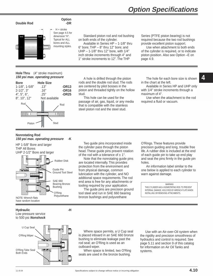
Specifications subject to change without notice or incurring obligation
4
5
11-8-04
Option Specifications Option
Double Rod -DR
Nonrotating Rod150 psi max. operating pressure -K
HP 1-5/8" Bore and largerTHP All BoresUHP 2-1/2" Bore and larger
Hole Thru (4" stroke maximum)150 psi max. operating pressure
Bore Hole Size1-1/8", 1-5/8" .13" -DR132-1/2", 3" .16" -DR164", 5", 6", .25" -DR258", 10", 12" Not available
Hydraulic -HLow pressure serviceto 500 psi Nonshock
Standard piston rod and rod bushingon both ends of the cylinder.
Available in Series HP – 1-1/8" thru6" bore; THP – 8" thru 12" bore; andUHP – 1-1/8" thru 12" bore, with 1/4"inch stroke increments through 4" and1" stroke increments to 12". The THP
Series (PTFE piston bearing) is notrequired because the two rod bushingsprovide excellent piston support.
Use when attachment to both endsof the cylinder is required, or to indicatepiston position. Also see Option –E onpage 4.9.
H + strokeSee page 4.5 fordimension “H”.Typical for ALLbores and ALLmounting styles.
A hole is drilled through the pistonrods and the double rod stud. The rodsare centered by pilot bosses in thepiston and threaded tightly on the hollowstud.
This hole can be used for thepassage of air, gas, liquid, or any mediathat is compatible with the stainlesssteel piston rod and the steel stud.
The hole for each bore size is shownin the chart at the left.
Available in Series HP and UHP onlywith 1/4" stroke increments through amaximum of 4".
Use when the attachment to the rodrequired a fluid or vacuum.
U Cup Seal
O'Ring Tube SealBoth Ends
O'Ring Wiper
RodRod
Piston Stud
Two guide pins incorporated insidethe cylinder pass through the pistonhead. These guide pins prevent rotationof the rod with a tolerance of ± 1°.
Note that the nonrotating guide pinsare located internally. This providesprotection from the environment andfrom physical damage, commonlubrication with the cylinder, and NOadditional space requirements. The rodend area is free for any attachments ortooling required by your application.
The guide pins are precision groundtool steel and run in SAE 660 bearingbronze bushings and polyurethane
Where space permits, a U Cup sealis placed inboard in an SAE 660 bronzebushing to eliminate leakage past therod seal; an O'Ring is used as anoutboard wiper.
When space is limited, two O'Ringseals are used in the bronze bushing.
O'Rings. These features provideprecision guiding and long, trouble freelife. A rubber disk is included at the endof each guide pin to take up end playand seat the pins firmly in the guide pinholes.
An information label similar to theone below is applied to each cylinder towarn against damage.
WARNINGTHIS CYLINDER HAS A NONROTATING ROD. TO PREVENTINTERNAL DAMAGE, HOLD ROD BY WRENCH FLATS WHENINSTALLING OR REMOVING ATTACHMENTS.
Use with an Air-over-Oil system whenthe rigidity and precision smoothness ofhydraulics and control is required. Seepage 5.11 and section 9 of this catalogfor information on Air Oil Tanks andsystems.
Guide PinGround Tool Steel
Rubber Disk
SAE 660Bearing BronzeBushing
O'RingPolyurethane
NOTE: Wrench flatshave random location
4.10

Specifications subject to change without notice or incurring obligation
4
5
Original Series(shown right)• Bores 1-1/8" thru 12"• Strokes 1/2" thru 12"• Forces to 44,000 lbs. (22 tons!)
Pancake® Series(see pages 5.13 to 5.14-4)• Bores 1/2" thru 4"• Strokes 1/8" thru 1-1/2"• Forces to 7,186 lbs
Square1® Series(see pages 5.15 to 5.16-4)• Bores 3/4" thru 2"• Strokes 1/8" thru 2-1/2"• Forces to 870 lbs.
Available in 4 seriesBore sizes 1/2" thru 12"Strokes 1/8" thru 12"
Multi-Power ® Cylinders
Load Capacity (psi)Machine Design 1972/73Bearing Reference Issue
Porous Bronze ............ 4,500Porous iron ................ 8,000Phenolics ................... 6,000Nylon® ....................... 1,000TFE ............................ 500Reinforced Telfon® .... 2,500*TFE fabric ................ 60,000Polycarbonate ............ 1,000Acetal ........................ 1,000Carbon-graphite ........ 600
* Shows Duralon bearing classification. Not to be used for design purposes.
Friction PropertiesSlip-
Coefficient stickSteel-on-steel ............... .50 YesBronze-on-steel ............. .35 YesSintered Bronze-on-steel with mineral oil ...... .13 NoBronze-on-steel with mineral oil ...... .16 NoCopper lead alloy-on-steel .22 YesAcetal-on-steel ............. .20 NoNylon-on-steel ............. .32 YesDuralon-on-steel .......... .05 - .16 No
Duralon® Rod Bearings Excel
Printed with permission by Rexnord Corp.
Longstroke™ Series(see pages 5.17 to 5.18-5)• Bores 2" thru 4"• Strokes 1/2" thru 12"• Forces to 7,186 lbs
10-30-04
Features & Benefits
More force from available shop air . . . . . . . Eliminates hydraulics – stays clean
Multiple pistons on the power stroke . . . . . . Saves mounting space (44 to 75%)
Single piston on the retract stroke . . . . . . . . Saves air (22 to 37%)
Building block design . . . . . . . . . . . . . . . . . Low cost – Quick delivery – Specials
Wide range of models, sizes and options . . Adapts to your application requirements
Corrosion resistant construction . . . . . . . . . Long life – clean appearance
Internally lubricated dynamic seals . . . . . . . Smooth operation and long product life
Duralon rod bearings . . . . . . . . . . . . . . . . . See chart above – extended product life
Hard anodized ID cylinder tubing . . . . . . . . More cycles – less wear
2 Year warranty . . . . . . . . . . . . . . . . . . . . . . Extended buyer protection
5.1

Specifications subject to change without notice or incurring obligation
4
5
How it works
• Duralon® rod bushing. (see page 5.1 for tableof physical properties)
• Female rod end with wrench flats
• Internally lubricated Buna-N O-ring
piston and rod seals.
• Airline lubrication recommended
• Media . . . . . . . . . . . . . . . . . . . . . . . . . . Air
• Max. operating pressure . . . . . . See chart
• Min. pressure recommended . . . . . 20 psi
• Ambient & media temp. . . -25° to +250°F• Prelubrication . . . Magnalube® –G Grease
Get forces up to 44,000 pounds from shop air pressure!
Sizing Guide
3-24-03
Single
Stage
Ret
ract
Piston
Are
a, sq
. in.
Tota
l Effe
ctive
Pist
on
★
Area-
Squar
e In
ches
Bore Inch
es
Stages
(Num
ber o
f Pist
ons)
Equiva
lent B
ore
of a
Single
Piston
Cyli
nder
Base W
eight
, lb.
Zero
Stroke
Weig
ht Per
inch,
lb.
of Stro
ke
++
Rod D
iamet
er, in
.
Rod A
rea,
sq. in
.
Forc
e@ 6
0 ps
i
Max. O
perat
ing P
ressu
re
★ Areas given are for Multiple Stage Extend - Single Stage Retract witha Single Rod. For Single Stage Extend - Multiple Stage Retract and anyDouble Rod Models, deduct the rod area shown.‡ Areas given are for Standard Single Stage Retract. For Single StageExtend with a single rod, add the rod area shown.
Ratings – Standard Units
Notes
2 1.8 1.5 108 0.9 0.31-1/8 3 2.6 1.8 156 0.8 0.50 0.2 1.1 0.4 150
4 3.4 2.1 204 1.3 0.52 3.8 2.2 228 1.7 0.4
1-5/8 3 5.6 2.6 336 1.7 0.62 0.3 2.0 0.6 1504 7.3 3.0 438 2.4 0.82 9.4 3.5 564 3.6 0.8
2-1/2 3 13.8 4.2 828 4.5 0.75 0.4 4.6 1.2 1504 18.3 4.8 1098 5.5 1.52 13.7 4.1 822 4.5 0.8
3 3 20.3 5.1 1218 6.6 0.75 0.4 5.5 1.2 1504 26.9 5.8 1614 6.6 1.52 24.4 5.6 1464 7.8 1.2
4 3 36.1 6.8 2166 11.8 1.00 0.8 9.5 1.6 1504 47.9 7.9 2874 11.2 2.12 38.0 7.0 2280 12.3 1.4
5 3 56.4 8.5 3384 18.4 1.25 1.23 15.7 2.1 1504 74.8 9.7 4488 19.0 2.82 55.3 8.4 3318 14.7 1.5
6 3 82.3 10.2 4938 27.0 1.25 1.23 18.1 2.2 1504 109.4 11.8 6564 21.7 2.92 98.6 11.2 5916 41.5 2.3
8 3 147.0 13.7 8820 48.5 1.50 1.7 51.5 2.9 1504 195.4 15.8 11724 61.4 3.62 153.9 14.0 9234 85.1 5.4
10 3 229.3 17.1 13758 75.4 2.00 3.1 110.3 8.1 1504 304.7 19.7 18282 135.4 10.82 222.9 16.8 13374 116.6 7.0 150
12 3 332.8 20.6 19968 109.9 2.00 3.1 153.0 10.5 1304 442.7 23.7 26562 189.5 14.0 100
Fabco-Air attaches multiple pistons to acommon shaft and provides internal airpassages through the shaft to all pistons.Thus, when shop air pressure is applied tothe extend port, all pistons are pressurizedsimultaneously enabling tremendous thrustforces to be obtained.
See the handy sizing guide below for avail-able force multiplying factors (column 3 –Total Effective Piston Area) and maximumoperating pressures for various cylinderbore sizes.
Sizing Example
MP3 x 1 - 3 - 1 - FF
Piston Area is 20.3 sq. in.
Force = Pressure x Area
If Supply Air Pressure is 100 psi,
then Force = 100 psi x 20.3
or Force = 2030 lbs
5.2
Shop AirSupply to
Extend PortAtmosphericAir Exhaust
AtmosphericAir Exhaust
AtmosphericAir Exhaust
ExhaustAir
Internal Air Passages
Piston #1Piston #2Piston #3Piston #4
ExhaustAir
AtmosphericAir Drawn In
AtmosphericAir Drawn In
AtmosphericAir Drawn In
Shop AirSupply to
Retract Port

Specifications subject to change without notice or incurring obligation
4
5
Basic Construction
10-30-04
Multi-Power® Cylinders
Cylinder OD – is clear anodized aluminum for corrosionresistance and an attractive appearance.
The Bore ID is Hard Anodized – Hard anodizing isan electrochemical process which provides a very densesurface of aluminum oxide that actually impregnates thebase aluminum. It forms an extremely hard (60 Rc) sur-face with a low coefficient of friction. Hardness, corrosionresistance and wear resistance exceeds that of chromeplated steel.
An Extra Long Rod Bearing – provides long andrigid support for the piston rod. The bearing material isDuralon® on all bore sizes. See page 5.1 for a chart com-paring the exceptional physical properties of Duralon® toother, less durable, bearing materials.
The Piston Rod – is Hard Chrome Plated StainlessSteel. Surface finish is 12 RMS or better.The standardrod end is fine female thread tapped and has long wrenchflats.
Piston Construction – The piston is aluminum for lightweight. The piston rod pilot end and a pilot washer enablebolting the assembly securely while maintaining preciseconcentricity for smooth cylinder performance.
Dynamic Seals – Internally lubricated O'Rings are com-pounded to provide extra long wear, lower breakaway(starting) and running friction, and smoother operation. Intests, cylinders with these seals have extended cycle life2 to 3 times beyond cylinders with standard Buna-N seals.
1 12 2 3 4 NPT Port
Multiple ExtendPower Stroke
Single RetractReturn Stroke
15 14 13 15
8
10
6
7
11
NPT Port
19 18
17
16
21
3
20
7
9
5
1 12 2 3 4 NPT Port
Single ExtendReturn Stroke
Multiple RetractPower Stroke
15 14 13 15
8
10
6
7
11
NPT Port
19 18
17
16
21
3
20
7
9
5
Multiple Stage Retractwith Single Stage Extend
Multiple Stage Extendwith Single Stage Retract
No. Description
1 Cylinder tube seal2 Atmospheric vent3 Piston rod4 Air passage between stages5 Center stud, high tensile, plated6 Stainless steel tie rods and plated steel nuts7 Piston stop8 Cap End Plug, aluminum, black anodized9 Nut, plated steel10 Piston Rod Pilot Washer locates piston
to maintain precise concentricity11 Cap end head, aluminum, black anodized12 Cylinder tube, aluminum13 Baffle, aluminum14 Baffle seal, Buna-N O'Rings, –25° to + 250°F15 Piston seal, internally lubricated O'Ring16 Piston rod seal, internally lubricated O'Ring17 Center shaft seal, internally lubricated O'Ring18 Piston, aluminum19 Piston air slot, note direction of air flow20 Rod end head, aluminum, black anodized21 Piston rod bushing, anodized aluminum
housing with Teflon® lined Duralon® insert
Quick Reference to Components
5.3

Specifications subject to change without notice or incurring obligation
4
5
How to Order
1-2-07
Description Specify See Page1"–14 Rod thread – 8" bore only -KF 5.5Double Rod -DR 5.8Nonrotating Single Rod ‡ -NR 5.8Nonrotating Double Rod ‡ -NRDR 5.8Male Rod Thread 5.7
Single Rod -MRDouble Rod, Rod End -MRDouble Rod, Cap End -MR1Double Rod, Both Ends -MR2
Viton Seals (-15° to +400°F) -V 5.8Shock & Speed Control using ‡ -HS 5.11
Hydraulics, 2-1/2" – 12" boresRubber Bumpers 5.9
Rod End -BFCap End -BRBoth Ends -BFR
Adjustable Extend Stroke -AS 5.96" Stroke maximum. Full strokeadjustment is standard.
1/2" NPT Ports in Heads ‡(2-1/2", 3", 4", 5" & 6" Bores only) 5.10Rod End Head -TFCap End Head -TRBoth Heads -TFR
3/4 NPT Ports in Heads -P34 5.10(8", 10" & 12" Bores only)
Extend Port Bushing 5.103/8 NPT (2-1/2" – 6" Bores) -E381/2 NPT (2-1/2" – 6" Bores) -E123/4 NPT (5" – 12" Bores) -E34
High Flow Vents -HF 5.10Port Positions 5.5 & 5.6
All Ports Position #1 StandardPosition #2 -PA2Position #3 -PA3Position #4 -PA4
Rod End Position #1 StandardPosition #2 -PR2Position #3 -PR3Position #4 -PR4
Cap End Position #1 StandardPosition #2 -PC2Position #3 -PC3Position #4 -PC4
Atmospheric Vent or Ported Baffle PortPosition #1 StandardPosition #2 -PB2Position #3 -PB3Position #4 -PB4
Any port or vent not specified will be inPosition #1 as shown on page 5.5 & 5.6Magnetic Piston ‡ -E 5.12
for reed switches and Electronic Sensors(Order Sensors separately)
‡ Note: Additional cylinder length requiredfor Nonrotating Rods see page 5.8;for Option -HS see page 5.11;for 1/2 NPT Ports Option see page 5.10;for Option -E see page 5.12
OPTIONS
Model Number Code
x –1 3 – 1 FFMP3
How to Order1. Specify Series and Bore2. Specify Stroke in Inches and Fractions. Note standard strokeslisted above. Strokes not listed are available to 12" maximum at anominal increase in delivery time and cost.3. Specify stages extend4. Specify stages retract5. Specify Mounting6. Specify Options
ExampleMP3 x 1 – 3 – 1 – FF – MRMulti-Power® Series, 3" bore, 1" stroke, 3 Stage Extend, 1 StageRetract, Front Face (Fabco Pattern) Mount, Male Rod Thread.
MPSeries& Bore
1-1/8"1-5/8"2-1/2"
3"4"5"6"8"
10"12"
– MR
Stages StagesExtend Retract
2 — 13 — 14 — 11 — 2‡
1 — 3‡
1 — 4‡
Standard available combinationsare listed above. See page 5.7 forMultiple Extend–Multiple RetractOptions.‡Note: Applicable only to 1-1/8" thru 8" bores.
–
StandardStrokes
1/2"1"
1-1/2"2"
2-1/2"3"4"5"6"
OptionalStrokesany other
stroke0" thru 12"
Bores Mounting1-1/8" Front Face – Fabco Pattern ................................ –FFthru Front Face – NFPA (MF1) Pattern .................... –FFA6" Rear Face – Fabco Pattern ................................ –RF
Rear Face – NFPA (MF2) Pattern .................... –RFAFoot .................................................................... –FTClevis Mount NFPA (MP1) Dimensions
for single stage retract onlyPorts in-line with slot ................................... –PMPorts 90° to slot .......................................... –SM
Extended Tie Rods(See page 5.6 for non-standard lengths.)
Rod end only ............................................... –WFCap end only ............................................... –WRRod and Cap Ends ...................................–WFR
Front Face – NFPA (ME3) Pattern .................... –FFA8" Rear Face – NFPA (ME4) Pattern .................... –RFA
10" Extended Tie Rods12" Rod end only ............................................... –WF
Cap end only ............................................... –WRRod and Cap Ends ...................................–WFR
5.4

Specifications subject to change without notice or incurring obligation
4
5
A= (No. stages x stroke) + y‡
Bore1-1/81-5/82-1/2
345681012
B2.002.503.633.885.006.007.007.579.4011.10
y‡ (2 stage)1.862.422.912.912.913.813.466.257.757.75
y‡ (3 stage)2.413.083.763.763.765.154.558.25
10.7510.75
y‡ (4 stage)2.963.754.614.614.616.505.65
10.2513.7513.75
Dimensions (inches)
C1.251.752.382.753.754.505.25NANANA
D2.503.004.254.506.007.008.00NANANA
E1.752.253.003.505.006.007.009.0012.0014.00
F.28.28.34.34.41.53.53.69.78.78
G.13.13.19.19.19.19.19.25.25.25
H.50.50.50.50.50.69.691.001.001.00
J±.0020.7521.0011.1271.1271.5021.7521.7522.0012.7512.751
±.0010.5000.6250.7500.7501.0001.2501.2501.5002.0002.000
MK†
5/16-24x.633/8-24x.631/2-20x.751/2-20x.751/2-20x.753/4-16x1.133/4-16x1.131-12x1.50†
11/2-12x1.7511/2-12x1.75
L7/161/25/85/87/811
1-1/41-3/41-3/4
N7/167/169/169/163/43/43/43/4
1-1/81-1/8
P2.382.883.694.135.506.253.38NANANA
NPT1/81/81/41/41/41/41/41/21/21/2
QR
.50
.63
.75
.75
.75
.75
.751.501.501.50
‡ Note:The “Dimension Y” is for standard models: Multiple extend/single
retract and Single extend/multiple retract. Optional Multiple extend/multiple retract models require additional cylinder length (see page 5.7).
The following options also require additional cylinder length. See therespective option information pages for details. -NR, –NRDR (pg 5.8),-HS (pg 5.11), -TF, -TR, -TFR (pg 5.10), -E (pg 5.12).
† Note:“Dimension K” for 8" Bore only, specify Option –KF for 1"-14 Rod Thread
3-24-03
Multi-Power® Cylinders
-RF Rear Face Mount; Cap End Rectangular FlangeFabco mounting pattern
T T
RRA
GH
MJ
U
AOThd
NHex Nut4 PlacesRod End
Q1
2
3
4
LS
E
K
S
C
E
BD
F
-FF Front Face Mount; Rod End Rectangular FlangeFabco mounting pattern
T T
RRA
GH
MJ
UAOThd
NHex Nut4 PlacesCap End
Q1
2
3
4
LS E
K
S
C
E
BD
F
1-1/8", 1-5/8", 2-1/2", 3", 4", 5", & 6" Bores
-RFA Rear Face Mount; Cap End Rectangular FlangeNFPA (MF2) mounting pattern
T T
RRA
G
H
MJ
NHex Nut4 PlacesRod End
U
AOThd
Q 1
2
3
4
LS
E
K
S
CCE
BBDD
FF
FABCO 1-5/8" = NFPA 1-1/2"FABCO 3" = NFPA 3-1/4"
-FFA Front Face Mount; Rod End Rectangular FlangeNFPA (MF1) mounting pattern
T T
RRA
GH
MJ
U
NHex Nut4 PlacesCap End
AOThd
Q1
2
3
4
LS
E
K
S
CCE
BBDD
FF
FABCO 1-5/8" = NFPA 1-1/2"FABCO 3" = NFPA 3-1/4"
For single stage retract onlyClevis Mount (NFPA MP1 Dimensions)-PM - Ports in-line with slot-SM - Ports 90° to slot
T T
RRA
GH
MJ
URF
FL
CD Pin
ERLR
CW CW
CB
ECL
Cross Pin andClips Included
N Hex Nut 4 Places Both Ends 2-1/2" thru 6" Bores;Rod end only 1-1/8" & 1-5/8" Bores
Fabco 1-1/8" = NFPA 1-1/2"Fabco 1-5/8" = NFPA 1-1/2"Fabco 3" = NFPA 3-1/4"
Material: Gray Iron Casting,Black Oxide Finish
5.5

Specifications subject to change without notice or incurring obligation
4
5
Bore1-1/81-5/82-1/2
345681012
S1.191.622.312.693.504.255.137.9010.6312.46
T.22.25.31.31.31.31.31.75.75.75
U.27.27.38.38.50.50.50.50.80.80
X.31.38.44.50.63.75.75NANANA
BB2.002.753.884.695.446.637.63NANANA
Z.44.63.56.75.881.001.00NANANA
AO1/4-201/4-203/8-163/8-161/2-131/2-131/2-131/2-133/4-103/4-10
WNANANANANANANA4.565.005.81
CC1.001.432.192.763.324.104.88NANANA
DD2.503.254.505.316.387.638.63NANANA
FF.22.28.34.41.41.53.53NANANA
FO3.003.504.384.886.387.257.00NANANA
HC1.131.381.752.002.753.253.75NANANA
HT2.002.503.253.755.256.257.25NANANA
WF1.01.01.31.41.41.81.82.32.682.68
WR1.01.01.31.41.41.81.82.3
2.682.68
V.22.22.33.33.43.43.43.43.66.66
CD.500.500.500.750.750.7501.000NANANA
FL.75.75.751.251.251.251.50NANANA
RF.38.38.38.63.63.63.75NANANA
CB.76.76.76
1.261.261.261.51NANANA
CW.50.50.50.62.62.62.75NANANA
ER.62.62.62.87.87.871.25NANANA
LR.62.62.62.87.87.87
1.13NANANA
CL2.092.092.092.882.882.883.38NANANA
Mounting Styles with Dimensions
3-24-03
-FT Foot Mount
XX
T T
RR
A
GH
MJ
NHex Nut4 PlacesBoth Ends
.25Z Z
Q 1
2
3
4
LS
P
K
S
FO
HT
HC
E
F
-WF Extended Tie Rod Mount, Rod End Only-WR Cap End Only-WFR Rod & Cap Ends
VV
T T
RR
A
GH
MJ NHex Nut4 PlacesBoth EndsALLModels
WF WR
AOThd
Q1
2
3
4
LS
E
K
SE
To OrderExtended Tie Rod Mount
Specify SuffixRod End only –WFCap End only –WRRod & Cap Ends –WFR
If a non-standard extensionis required, specify by add-ing the required length tothe suffix.e.g. If –WF length requiredis 2.5", Specify –WF2.5"
▼
1-1/8", 1-5/8", 2-1/2", 3", 4", 5", & 6" Bores
-WF Extended Tie Rod Mount, Rod End Only-WR Cap End Only-WFR Rod & Cap Ends
Q1
2
3
4
WL
SE
K
V
T T
RRA
GH
MJNHex Nut8 PlacesBoth Ends
WF WR
AOThd▼
8", 10", and 12" Bores
-FFA Front Face Mount; Rod End Square FlangeNFPA (ME3) mounting pattern
QRod End View 1
2
3
4
WBS
E
AO Thd
F
U
T T
RRA
GH
MJ
K
NHex Nut8 PlacesCap End
L
-RFA Rear Face Mount; Cap End Square FlangeNFPA (ME4) mounting pattern
UT T Q Cap End View1
2
3
4
WB
SE
AOThd
FRR
AG
H
MJ
K TapL Flats
NHex Nut8 PlacesRod End
5.6

Specifications subject to change without notice or incurring obligation
4
5
Multi-Power® Cylinders
When required return forces (Extendor Retract) are greater than the standardsingle piston can provide, multiplestages (pistons) can be pressurized.This is accomplished by replacing oneor more of the standard baffles with aported baffle as shown in the illustration.When these thicker baffles are used, theoverall length (“Dimension A”) increases.See the chart below for port size anddimension details.
Multiple Stages Extend& Multiple Stages Retract(Not available on 10" and 12" bores)
10-30-04
No. of TotalAvailable Ported No. of
Combinations Baffles Stages2 – 2 1 23 – 2 1 33 – 3 2 32 – 3 1 34 – 2 1 44 – 3 2 44 – 4 3 43 – 4 2 42 – 4 1 4
Notes:When any of these combinations
are ordered, the proper number ofported baffles are included.
As standard, the largest number ofstages are internally connected.
On models with the same numberof extend and retract stages, theextend stages are internally con-nected.
Add to Dimension “A”Bore Port for each Ported Baffle
1-1/8" 1/8 NPT .50"1-5/8" 1/8 NPT .50"2-1/2" 1/4 NPT .50"
3" 1/4 NPT .50"4" 1/4 NPT .50"5" 1/4 NPT .50"6" 1/4 NPT .50"8" 1/2 NPT 1.00"
• Clean rooms, Vacuum Chambers,Wash Down Areas, Under Liquid,Dirty or Corrosive Environments
• Increase Cycle Speeds
• Selective Force Application
Applications that may dictate the use of Ported Baffles
Filters can be installed in the ports of stages not requiring pressurization, or theycan be plumbed to a common filter or point outside the critical environment.
The ports have higher air flow capacity than the vents in the standard baffle.
With control circuitry, the number of stages that are pressurized (thus the amountof force being applied) at any given time can be selected and varied. Consultengineering with application details.
Male Rod Thread OptionSingle Rod -MRDouble Rod, Rod End Only -MRDouble Rod, Cap End Only -MR1Double Rod, Rod & Cap Ends -MR2
For bores 1-1/8" thru 8", a highstrength stud is threaded into thestandard female rod end and retainedwith Loctite®. This method eliminates thesmall diameter thread relief areanormally required when machining malethreads. This provides a much stronger
Thread
rod end which can be repaired, rather thanreplacing the complete rod, should thethread be damaged. For 10" and 12", thethread is machined integral with the rod.
Rod Stud
Loctite®No ReliefNo Weakness
A + [ See Chart ]
Example: Model MP3x1-3-2-FF
Ports externallyconnected forMultiple Retract
Tube sealsNPTPort
Atmospheric Vent
Multiple ExtendPort
Ported Baffle Standard Baffle
5.7
See pages 5.5 for Dimension “A”
BORE THREAD1-1/8" 5/16–24 x .631-5/8" 3/8–24 x .882-1/2" 1/2–20 x 1.00
3" 1/2–20 x 1.004" 1/2–20 x 1.005" 3/4–16 x 1.506" 3/4–16 x 1.50
8" standard 1–12 x 1.508" optional‡ 1–14 x 1.50
10" 1-1/2–12 x 2.2512" 1-1/2–12 x 2.25
‡Note: Male rod callout must be preceeded by “-KF”

Specifications subject to change without notice or incurring obligation
4
5
Option Specifications
10-30-04
Nonrotating Rod Option -NR
A ported baffle is used so the pistonassembly can be retracted by the nextpiston back from the rod end. Thenormal rod head port becomes anatmospheric vent. The tolerance onrotation is ±1°.
The hex rod design does allow forsome torque loading on the shaft.However, torque loads that induce sideloading should be minimized for bestoverall life and performance.
OptionNonrotating Double Rod -NRDR
A combination of the Options –NR and –DR as shownabove. The rod end rod is Hex and the cap end rod isround. The ported baffles are included and the “Dimen-sion A” adjustments shown for Option –NR must bemade. Extended piston areas must also be reduced bythe rod area.
Add toDimension “A”
for eachBore Port Ported Baffle HR1-1/8" 1/8 NPT .50" .50"1-5/8" 1/8 NPT .50" .63"2-1/2" 1/4 NPT .50" .75"
3" 1/4 NPT .50" .75"4" 1/4 NPT .50" 1.00"5" 1/4 NPT .50" 1.38"6" 1/4 NPT .50" 1.38"8" 1/2 NPT 1.00" 1.50"10" 1/2 NPT .50" 2.00"12" 1/2 NPT .50" 2.00"
No. of TotalAvailable Ported No. of
Combinations Baffles Stages2 – 1 1 23 – 1 1 33 – 2‡ 2 34 – 1 1 44 – 2‡ 2 44 – 3‡ 3 4
‡ Note: Not applicable to 10" and 12" bores
A + [ See Chart ]
Ported Baffle
Atmospheric Ventfor all extend/retractcombinations
Retract Port
No rodseal
Hex Rod
A stainless steel hex rod and a hexbroached bushing of SAE 660 bearingbronze replaces the standard roundrod and bushing.
A + [ See chart ]
HRHex rod flats Random Rotationrelative to Mounting Pattern
Viton Seals Option -V Use for elevated temperatures (–15°to + 400°F) or compatibility with exoticmedia. Consult engineering for compat-ibility information.
Double Rod Option -DR
Standard piston rod and rod bushingon both ends of the cylinder.
For 8" bore only, when -KF isspecified, 1"–14 threads will be appliedat both ends.
Use when attachment to both endsof the cylinder is required, or to indicatepiston position. Also see Option –E onpage 5.12.
H + strokeSee page 5.5 fordimension “H”.Typical for ALLbores and ALLmounting styles.
Note: 10" & 12" Bores for Position Indication Only–Rod Thread 3/8-16 x 5/8 Deep
5.8
See pages 5.5 for Dimension “A”

Specifications subject to change without notice or incurring obligation
4
5
Adjustable extend strokeOption -AS
For strokes through 6"Full stroke adjustment is standard.
Note!To maintain operator safety featuresof this option, it is NOT available withmounting styles: -WR and -WFR.Use caution when mounting to avoidcreating pinch points.
Not available for 10" & 12" bores
Nut StopAdjustment Rod with fine pitch thread
(See Dimension “BF”)
Adjustment Nut with Mating Fine Pitch Thread
1/2"Minimum Clearance when fully stroked
Adjustment Nut SkirtLock ScrewPlastic Plug
Stop TubeRod Bushing
Contact Surfaces totally enclosed
Note: Use caution when mounting to avoid creating pinch points
Dial-A-Stroke® provides a rugged andprecision adjustment of the extend stroke ofthe cylinder. The stop tube, adjustment nutwith skirt, and minimum clearances combine toeliminate pinch points, thus providing operatorsafety. Note! Use caution when mounting toavoid creating pinch points with other parts ofyour machine design.
The stop tube is blue anodized aluminum,the adjustment nut is blackened steel with ablack anodized aluminum skirt, and the nutstop is red anodized aluminum; all for corro-sion resistance and appearance. The adjust-ment nut, steel for long life, includes a lockscrew with a plastic plug so that the adjust-ment nut can be locked in place withoutdamaging the threads. The nut stop ismounted on the end of the adjustment rod sothat the nut cannot come off. The fine pitchthreads on the adjustment rod and nut provideprecision adjustment. (See dimension "BF").Adjustment settings are simplified by conve-nient scale markings applied to nut skirt andstop tube.
+ (2 x Stroke)
+ Stroke
Bore 1-1/8" 1-5/8" 2-1/2" 3" 4" 5" 6" 8"
BA 1.13 1.25 1.50 1.50 2.00 2.25 2.25 2.50
BB 1.50 1.50 2.00 2.00 2.00 2.25 2.25 2.75
BC 1.67 1.67 1.90 1.90 1.67 1.67 1.67 2.54
BD 1.00 1.00 1.00 1.00 .75 .75 .75 1.13
BE .50 .50 .75 .75 .75 .75 .75 1.16
BF .050 .050 .063 .063 .063 .071 .071 .071
10-26-04
Rubber Bumpers Option
Rod End only -BFCap End only -BRBoth Rod & Cap Ends -BFR
Standard rubber mass will compress and give fullstroke at 60 to 80 psi. This mass can be adjustedto meet your specific pressure and/or dynamicload requirements.
Rubber Bumpers
Multi-Power® Cylinders
BC + (2 x Stroke)
BD + StrokeBE + Stroke
BB Diameter
BFStroke adjustmentper revolution
BADiameter
A rubber doughnut is bonded to thecylinder head to act as the piston stopand absorb the impact of the piston.This reduces noise and absorbs energy,thus reducing damage to the cylinderand tooling due to pounding. Theamount of rubber that extends beyondthe normal piston stop is designed tocompress and allow full stroke of thecylinder at 60 to 80 psi. If your applica-tion uses lower pressure or has highenergy, consult engineering with appli-cation details so that rubber mass canbe adjusted to meet your specific re-quirements.
Because of the temperature limitationsof the adhesives involved (-25° to +225°F),rubber bumpers are available in cylinderswith standard internally lubricated Buna-N seals only.
Use where noise reduction and im-pact absorption is desired.
Note! On applications such as punch-ing, shearing, setting blind rivets, etc.,where high forces are built up and thenreleased VERY quickly, the proper methodof “catching” this type of load is to adjustthe cylinder piston and the tooling so thatat the point of breakthrough the piston isvery close to the bumper. This reduces thedynamic load that the piston and bumperare required to absorb.
5.9

Specifications subject to change without notice or incurring obligation
4
5
Extend Port Bushing Option3/8 NPT (2-1/2" – 6" bores) -E381/2 NPT (2-1/2" – 6" bores) -E123/4 NPT (5" – 12" bores) -E34
The cap end plug is replaced with an extendedplug of black anodized aluminum with a femaleNPT port. The standard cap end port is plugged.
Use for plumbing convenience, or when higherair flows are required for higher cycle speeds.
1/2 NPT Ports in Heads Option 2-1/2", 3", 4", 5", & 6" Bores only
Rod End Head -TFCap End Head -TRBoth Heads -TFR For 2-1/2" thru 6" bores, thicker heads
(to accept 1/2 NPT ports) replace thestandard heads. Because of the thickerheads, there is an increase in Dimension“A” and a reduction of the rod extensionas charted below. With this construction,an O'Ring replaces the fiber gasketcylinder tube seal.
For 8", 10" and 12" bores, 3/4 NPTports are applied to standard heads.
Use when higher cycle speeds arerequired.
3/4 NPT Ports in BOTH Heads8", 10" & 12" Bores only -P34
Standard portplugged
ExtendedCap End Plugwith FemaleNPT Port
AZ
BZ
Extend Port
CZWrench Flats
Bore2-1/2
345681012
AZ.38.38.38.38.38.31.50.50
Dimensions (inches)
BZ1.131.131.501.751.751.752.752.75
CZ.94.941.261.501.501.502.252.25
E38 ✓✓✓✓✓–––
E34–––✓✓✓✓✓
E12✓✓✓✓✓–––
Availability
HH-DR + StrokeOption -DR only
HH
QCNPT
A + [See chart ]
TCRC
TRRR
QRNPT
1-19-07
High Flow Vents Option -HF The atmospheric vent in the baffle is cut largerto provide less resistance to the air flow.Use when higher cycle speeds are required.
Option Specifications
See pages 5.5 & 5.6 for Dimension “A”
5.10
A.38.38.760.00
Addto
QC1/41/21/23/4
QR1/21/41/23/4
RC2-1/2 &3" Bore
0.751.001.00
–
RC4, 5 &
6" Bore
0.751.251.25
–
RC8, 10 &
12" Bore
–––
1.50
RR2-1/2 &3" Bore
1.000.751.00
–
RR4, 5 &
6" Bore
1.250.751.25
–
RR8, 10 &
12" Bore
–––
1.50
HH2-1/2, 3 &4" Bore
0.120.500.12
–
HH5 & 6"Bore
0.310.690.31
–
HH8, 10 &
12" Bore
–––
1.00
OptionTFTR
TFRP34
HH-DR2-1/2, 3 &4" Bore
0.500.120.12
–
HH-DR5 & 6"Bore
0.690.310.31
–
HH-DR8, 10 &
12" Bore
–––
1.00
TC.31.50.50.63
TR.50.31.50.63
O'Ring Tube SealBoth Ends

Specifications subject to change without notice or incurring obligation
4
5
10-30-04
Multi-Power® Cylinders
Speed & Shock ControlUsing Hydraulics Option -HS
Available in 2-1/2" through 12" BoreTemperature range: –25° to + 250°F
Available with Viton seals Add -VTemperature range: –15° to +400°F
Note!!!All 4-Stage Units 2-1/2" thru 10" Boresare rated at 120 psi maximum air input!12" Bore, 3-Stage is rated at 130 psi max.12" Bore, 4-Stage is rated at 100 psi max.
Application TipsTwo Speed & Shock ControlSingle air/oil tank with sequence,needle and shut-off valves give:
1. Rapid “Extend” stroke.
2. Automatic switch to controlledrate when resistance is met andpressure builds up.
3. Fluid catches cylinder whenbuilt-up forces are suddenlyreleased (such as in punchingapplications), thus controllingthe shock that could otherwiseoccur.
Air supply
Muffler
Directional control4-way air valve
Single tankair/oil unit
Shut-off – 2-way oil
Multi-Power® Cylinder
Sequencevalve
Needlevalve
Always use 2-hand anti tie-downsystems for operator safety!Consult your local distributor forinformation and product delivery
4. Automatic return to rapid rateon “Retract” stroke.
One Speed CircuitSingle air/oil tank and flow controlvalve give hydraulic control withspeed control on “Extend” strokewith rapid rate on “Retract” stroke.
Air supply
Muffler
Directional control4-way air valve
Single tankair/oil unit
Flow control
Multi-Power® Cylinder
See chart
When Multi-Power® cylinders areapplied to applications such aspunching or shearing, high inertialand impact forces are often encoun-tered. To capture these potentiallydestructive forces, and preventpossible damage to tooling andcylinder specify Option –˙HS.
The seals on the piston, piston rodand tube are increased in the singlereturn stage (retract or extend) andfluid is used to control speed andshock. Fluid from an air-over-oil tankis used for the return media. This fluidpasses through a resistance, such asa flow control, which provides speedcontrol of the cylinder. When thematerial shears and the cylinder triesto complete its stroke, the non-compressible fluid resists rapidmovement, providing shock andspeed control. Note the circuits shownbelow.
For less fluid restriction and largerplumbing on 2-1/2" through 6" bores,see the 1/2 NPT porting options –TF,–TR, and –TFR on page 5.10. Also for10" & 12" bores, 3/4 NPT Port Option-P34 is available. See page 5.10.
Note!! The fluid pressure in the returnstage is limited to 500 psi. This dictatesthat all 4-stage units thru 10" bore belimited to 120 psi maximum air input! 12"bore, 3 stage units are limited to 130 psi;4 stage units are limited to 100 psi.
Use when smooth, rigid, and precisionspeed control is required. Also withapplications such as punching, shear-ing, setting blind rivets, etc., where highforces are built up and then releasedvery quickly. The fluid, being incom-pressible, “catches” these forces, bothstatic and dynamic, dissipating thembefore the cylinder reaches the end ofits stroke – and before the piston canpound on the piston stop.
1/2 NPT Porting is available for2-1/2", 3", 4", 5", & 6" Bores;3/4 NPT Porting is available for10" & 12" Bores
Additional Tube Seal, O'RingAdditional Piston Seal, Polypak®
Standard Piston Seal, O'RingThicker Piston
Standard Rod Seal, O'Ring
Additional Rod Seal, Polypak®
SAE 660 Bronze BushingThe Polypak® sealscombine an automaticlip seal with an O'springenergizer for excellentsealing from 0 to 500 psi.
Serie
s M
PM
LR, M
LS
Bore2-1/2", 3", 4"
5"6"8"
10", 12"Bore
2, 2-1/2", 3", 4
Add to “A” Pg 5.5 & 5.60.50"0.25"0.50"0.25"0.00"
Add to “B” Pg 5.18
0.50"
5.11

Specifications subject to change without notice or incurring obligation
4
5
Bore 1-1/8" 1-5/8" 2-1/2" 3" 4" 5" 6" 8" 10" 12"T .38 .38 .38 .38 .36 .25 .14 .10 .38 .38L 1.00 1.00 1.00 1.00 1.00 1.00 1.00 1.00 1.00 1.00
(T) Clamp Stick Out & (L) Length Adder to Dim. 'A' Pgs. 5.5 & 5.6
749 Series Sensor with Integral Clampfor 4" to 12" Bore Cylinders(shown prewired)
• Option -E consists of a magnet bonded into the piston head.When the piston magnet moves past an external sensor, the mag-netic field activates the sensor without physical contact.
• Mounting – The sensor is attached to a 2-part clamp that at-taches rigidly to a tie rod and can be positioned anywhere along thelength of the cylinder for very precise signaling.
• Two sensor styles are used – (a) the 9-2A197 Series for 1-1/8"thru 3" bores requires a tie rod clamp, and (b) the 749 Series whichaccommodates the larger diameter tie rods of the 4" thru 12" boreswith an integral clamp.
• Reliability – The annular piston magnet is permanently bondedinto a groove in the piston. It is a polarized permanent magnet ofrubber bonded barium ferrite that is very stable and is not affectedby shock. Under normal usage it will remain magnetized indefinitely.
• Warning – External magnetic fields and/or ferrous objects mayaffect the strength of the piston magnet therefore affecting sensoractuation and piston position indication. Labels noting this are af-fixed to the cylinder.
• Please note there is an increase in base length of thecylinder to accomodate the magnet. Using the table below add'L' to Dimension 'A' on pages 5.5 & 5.6
9-2A197 Series Sensor & Clampfor 1-1/8" to 3" Bores
SocketHeadScrewQuick Disconnect
Sensor Shown
Magnetic Piston Option -ESpecifies Magnetic Piston
(Order Sensors and Sensor Clamps Separately)
Integral Clamp
Piston
Magnet, RubberBonded BariumFerrite
Tie Rod, Stainless Steel
Cylinder Head
Cylinder Tube
T
Sensor
WARNINGThis cylinder is equipped with a MagneticPiston for use with Magnetically OperatedSensors. Other Magnetic Sensitive De-vices Should be Kept at a Distance to AvoidInadvertent Operation.
8", 10", 12" Bores4" – 6" Bores
9 foot prewired sensor
Female Cordsets availablein 1, 2, & 5 meter lengths
1-1/8" – 3" Bores
Sensor Clamp
Piston
Magnet
Tie Rod, Stainless Steel
Cylinder HeadCylinder Tube
T
SensorT
Option Specifications
3-24-03
Sensor & Clamp Ordering Guide Warning! Do not exceed sensor ratings. Permanent damage to sensor mayoccur. Power supply polarity MUST be observed for proper operation of sen-sors. See wiring diagrams included with each sensor.
Length 1 Meter 2 Meter 5 Meter
Part No. CFC-1M CFC-2M CFC-5M
Length 2 Meter 5 Meter
Part No. CFC-2M-12 CFC-5M-12
Temperature Range: –20° to + 80°C (–4° to + 176°F)
Female Cordsets for9-2A197 Series
Quick Disconnect Sensors
Female Cordsets for749 Series
Quick Disconnect Sensors
ProductReed Switch
ElectronicElectronic
5-240 VDC/VAC, 1 Amp Max., 30 Watt Max., SPST N.O., 3.0 Voltage DropSourcing, PNP, 6-24 VDC, 1.0 Amp Max., 0.5 Voltage DropSinking, NPN, 6-24 VDC, 1.0 Amp Max., 0.5 Voltage Drop
Reed SwitchElectronicElectronic
Electrical Characteristics5-120 VDC/VAC, 0.5 Amp Max., 10 Watt Max., SPST N.O., 3.5 Voltage DropSourcing, PNP, 6-24 VDC, 0.5Amp Max., 1.0 Voltage DropSinking, NPN, 6-24VDC, 0.5Amp Max., 1.0 Voltage Drop
5-240 VDC/VAC, 1 Amp Max., 30 Watt Max., SPST N.O., 3.0 Voltage DropSourcing, PNP, 6-24 VDC, 1.0 Amp Max., 0.5 Voltage DropSinking, NPN, 6-24 VDC, 1.0 Amp Max., 0.5 Voltage Drop
Reed SwitchElectronicElectronic
Quick Discon. P/N9-2A197-13049-2A197-13339-2A197-1334
9 ft. Prewired P/N9-2A197-10049-2A197-10339-2A197-1034
749-000-504749-000-531749-000-532
749-000-004749-000-031749-000-032
749-111-504749-111-531749-111-532
749-111-004749-111-031749-111-032
LED Lighted Magnetic Piston Position Sensors: Bores 1-1/8" – 3"
LED Lighted Magnetic Piston Position Sensors: Bores 4" – 8"
LED Lighted Magnetic Piston Position Sensors: Bores 10" & 12"
9-2A197 Series Sensor Mounting Clamps – Part Number 800-200-000
5.12
T
T

Specifications subject to change without notice or incurring obligation
4
5
Pancake ®—Multi-Power ®
10-26-04
Series MKSpecificationsMedia ................................................... AirRecommended Minimum Pressure ...... 20 psiDuralon® rod bushing. .......................... See chart pg. 5.1Maximum Operating Pressure ............. 150 psiAmbient & Media Temperature ............. -25° to + 250°FPrelubrication ....................................... Magnalube®-G GreaseAirline Lubrication ................................ Recommended
Models -MK 1/2 and -MK 3/4 Note 1: Two #10-32 x .50 tappedmounting holes at each end
Models -MK 1-1/8 and -MK 1-5/8
A H Wrench Flat
90°
Y
BG
Z
C Bolt Circle
K
E – FemaleRod Thread
F – Rod Dia.
D – C'BoredJ – Thru Holes (2)
1/8 NPT Ports
A H – Wrench Flat90°
Y
B
GZ
C BoltCircle
E – Female Rod Thread
F – Rod Dia.
D – TappedMounting Holes (2 at each end)
10-32 Ports w/.38 Dia. S'face
Sizing Pancake® – Multi-Power ® Cylinders
‡ Area = Total effective piston area, square inches. † Equivalent Bore = Bore required for a single piston cylinder.
Series Stages Area Equivalent Force @ Retract BodyBore (Pistons) ‡ Bore † 60 psi Area O. D.
2 .35 .6 20MK 1/2 3 .50 .7 30 .15 1.13
4 .65 .9 352 .80 1.0 45
MK 3/4 3 1.16 1.1 70 .36 1.504 1.52 1.3 902 1.79 1.5 105
MK 1-1/8 3 2.59 1.8 155 .80 1.994 3.39 2.0 2002 3.83 2.2 230
MK 1-5/8 3 5.59 2.6 335 1.76 2.744 7.35 3.0 4402 5.84 2.6 350
MK 2 3 8.54 3.2 510 2.70 3.244 11.24 3.7 6702 9.38 3.3 560
MK 2-1/2 3 13.85 4.0 830 4.47 3.744 18.32 4.7 10952 13.70 4.0 820
MK 3 3 20.33 5.0 1215 6.63 4.244 26.96 5.7 16152 24.35 5.5 1461
MK 4 3 36.13 6.7 2168 11.78 5.504 47.91 7.7 2875
Available Strokes1/8" 1/4" 1/2" 3/4" 1" 1-1/2"• • • • •• • • •
• •• • • • •• • • •
• •• • • • •• • • •
• •• • • •
• •• •• • • •• ••• • • •• ••• • • •• ••• • • •• ••
Fixed DimensionsA
1.131.501.992.743.243.744.245.50
C0.881.191.692.382.813.253.815.00
J Dia––
0.200.200.270.270.270.27
E8-32 x .38 dp10-32 x .38 dp
5/16-24 x .63 dp3/8-24 x .75 dp1/2-20 x .88 dp1/2-20 x .88 dp1/2-20 x .88 dp5/8-18 x .88 dp
F.25.31.50.62.75.75.751.00
H3/16 x .111/4 x .117/16 x .111/2 x .115/8 x .115/8 x .115/8 x .117/8 x .18
G0.130.130.140.140.140.140.140.20
D#6-32 x .44 dp#8-32 x .44 dp
.32 C'Bore x .19 dp
.32 C'Bore x .19 dp
.38 C'Bore x .26 dp
.38 C'Bore x .26 dp
.38 C'Bore x .26 dp
.38 C'Bore x .26 dp
Y0.460.46
-0.520.520.640.640.70
Series BoreMK 1/2MK 3/4
MK 1-1/8MK 1-5/8
MK 2MK 2-1/2
MK 3MK 4
5.13

Specifications subject to change without notice or incurring obligation
4
5
10-26-04
Ordering Examples
Model No: Series Bore x Stroke – Stages Extend – Stages Retract
MK2 X 1-2-1Pancake®-Multi-Power®
2" Bore, 1" Stroke, 2 Stage Extend, 1 Stage Retract
MK 1-1/8 X 1/2-4-1-MRPancake®-Multi-Power®
1 1/8" Bore, 1/2" Stroke, 4 Stage Extend, 1 StageRetract, Male Rod
How to Order
Model Number Code
x –1 3 – 1MK 1-1/8
Bore1/2"3/4"
1-1/8"1-5/8"
2"2-1/2"
3"4"
– MR
Stages StagesExtend Retract
2 — 13 — 14 — 11 — 21 — 31 — 4
Standard available combinations arelisted above. Consult factory forMultiple Extend–Multiple RetractOptions.
StrokeSeries
See available strokesin the sizing guide
on page 5.13
Model -MK 2 Models -MK 2-1/2, -MK 3, and -MK4
A H Wrench Flat
Y
BG
ZC Bolt Circle
K
E – FemaleRod Thread
F – Rod Dia.
D – C'BoredJ – Thru Holes (2)
1/8 NPT Ports
72°
A H Wrench Flat
45°
Y
BG
Z
C – Bolt Circle
K
E – FemaleRod Thread
F – Rod Dia.
D – C'BoredJ – Thru Holes (4)
1/8 NPT Ports
Stroke1/81/41/21
1-1/21/81/41/23/41/41/2
MK 1/2
B1.882.132.883.884.882.382.883.884.883.884.88
Z1.551.802.553.554.552.052.553.554.553.554.55
2 Stages extend
MK 3/4
B1.882.132.883.884.882.382.883.884.883.884.88
Z1.551.802.553.554.552.052.553.554.553.554.55
B2.362.613.304.335.332.863.744.335.334.335.33
Z1.521.772.453.494.492.022.893.494.493.494.49
K2.032.282.96note1note12.533.40note1note1note1note1
Y0.520.520.700.990.990.520.890.990.990.990.99
MK 1-1/8
BNA3.303.804.805.80NANA4.805.804.805.80
ZNA2.963.464.465.46NANA4.465.464.465.46
KNA2.973.474.475.47NANA4.475.474.475.47
MK 1-5/8
BNA
3.524.025.026.02NA
5.02NA
6.026.02NA
KNA3.133.634.635.63NA4.63NA5.635.63NA
ZNA3.023.524.525.52NA4.52NA5.525.52NA
MK 2
BNA
3.393.894.895.89NA
4.89NA
5.895.89NA
KNA3.003.504.505.50NA4.50NA5.505.50NA
ZNA2.893.394.395.39NA4.39NA5.395.39NA
MK 2-1/2
BNA3.453.954.955.95NA4.95NA5.955.95NA
KNA3.103.554.555.55NA4.55NA5.555.55NA
ZNA2.963.464.465.46NA4.46NA5.465.46NA
MK 3
BNA3.704.205.206.20NA5.20NA6.206.20NA
KNA3.253.754.755.75NA4.75NA5.755.75NA
ZNA3.213.714.715.71NA4.71NA5.715.71NA
MK 4
3 Stages extend
4 Stages extend
Series Bore
Variable Dimensions
Suffix Options - See pages 5.14-2, -3, -4Stroke Collars: 1/8" -C1; 1/4" -C2; 3/8" -C3Threaded Nose Mount: Single Rod -F
Double rod, rod end -FDouble rod, cap end -F1Double rod, both ends -F2
Double Rod -DRMale rod thread: Single rod -MR
Double rod, rod end -MRDouble rod, cap end -MR1Double rod, both ends -MR2
Viton seals -VExternal guide, nonrotating
for load guiding -GFinish: ProCoat™ -NRubber Bumpers:1-1/8 Bores & Larger Rod end -BF
Cap end -BRBoth ends -BFR
Adjustable extend stroke1-1/8 Bores & Larger -ASClevis mount: Ports in-line with slot -PM
Ports 90° to slot -SMEye mount: Ports in-line with tang -EPM
Ports 90° to tang -ESMMagnetic piston & sensor mounting slot(s) -EOrder sensors separately.Extend Port Bushing3/8 NPT for 2" Bores and Larger -E381/4 NPT Ports for 1-5/8" Bores and Larger -P14
5.14
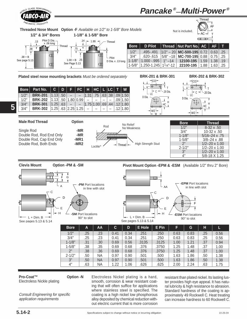
Specifications subject to change without notice or incurring obligation
4
5
5.14-2 10-26-04
Pancake ®—Multi-Power ®
Thread
AC
AF
TThreaded Nose Mount Option -F Available on 1/2" to 1-5/8" Bore Models
Plated steel nose mounting brackets Must be ordered separately
F G
A -PM Port locations in line with slot
H -SM Port locations 90° to slot
C
E
D
L + Dim. BSee pages 5.13 & 5.14
Clevis Mount Option -PM & -SM
AA-EPM Port locations in line with slot
H -ESM Port locations 90° to slot
C
E
D
L + Dim. BSee pages 5.13 & 5.14
F
Pivot Mount Option -EPM & -ESM (Available 1/2" thru 2" Bore)
Male Rod Thread Option
Single Rod -MRDouble Rod, Rod End Only -MRDouble Rod, Cap End Only -MR1Double Rod, Both Ends -MR2
.38
.13
.38 + BSee page 5.13
Thread
Pilot D Dia.x .06 long
.75
.14
Pilot D Dia. x .13 long.25
1.99 Thread
1.00 + BSee Page 5.13
Nut is included.1/2" & 3/4" Bores 1-1/8" & 1-5/8" Bore
Thread
Rod
High Strength StudLoctite®
No ReliefNo Weakness
Bore Thread1/2" 8-32 x .503/4" 10-32 x .50
1-1/8" 5/16–24 x .751-5/8" 3/8–24 x .88
2" 1/2–20 x 1.002-1/2" 1/2–20 x 1.00
3" 1/2–20 x 1.004" 5/8-18 X 1.25
Bore1/2"3/4"
1-1/8"1-5/8"
2"2-1/2"
3"4"
A.25.25.31.38.38.50.50.63
F0.630.631.001.251.251.631.632.00
C0.410.410.690.690.690.970.971.22
D0.340.340.560.680.680.900.901.06
E Hole.251.251.3135.376.376.501.501.626
E Pin.250.250
.3125
.3750
.3750.500.500.625
G0.830.831.211.481.481.861.862.24
H.25.25.37.37.37.50.50.63
AA.23.23.30.35.36NANANA
L0.560.560.941.001.001.381.381.75
Pro-Coat™ Option -NElectroless Nickle plating
Consult Engineering for specificapplication requirements
HHC
W/2W
C
L
LC.20 Dia.
D Dia.
T
C/2
BRK-202 & BRK-302
HHC
W/2W
C
L
LC.20 Dia.
D Dia.
T
C/2BRK-201 & BRK-301
Electroless Nickel plating is a hard,smooth, corrosion & wear resistant coat-ing that will often suffice for applicationswhere stainless steel is specified. Thecoating is a high nickel low phosphorousalloy deposited by chemical reduction with-out electric current that is more corrosion
resistant than plated nickel. Its lasting lus-ter provides high eye appeal. It has natu-ral lubricity & high resistance to abrasion.Standard hardness of the coating is ap-proximately 49 Rockwell C. Heat treatingcan increase hardness to 60 Rockwell C.
Bore1/2"3/4"
1-1/8"1-5/8"
AC0.720.881.591.88
Nut Part No.MC-500-195MC-700-19512100-19522100-195
D Pilot.495-.491.620-.615
1.000 -.9951.250-1.245
AF0.630.751.381.63
T.25.25.19.25
Thread1/2" – 205/8" –181" –14
11/4"-12
Bore1/2"1/2"3/4"3/4"
Part No.BRK-201BRK-202BRK-301BRK-302
C1.131.131.251.25
HC.75–
1.00–
H1.31
–1.75
–
T.09.09.12.12
F–
1.80–
2.25
D.50.50.63.63
W1.501.501.801.80
FC–
0.99–
1.25
L.63–
.69–
LC.38–
.44–

Specifications subject to change without notice or incurring obligation
4
5
5.14-310-26-04
Series MK Option Specifications
External Guide, Nonrotating
Option -G
Adjustable Extend Stroke Option -AS Available on bores 1-1/8" and larger. See description on page 5.9.
Note! Use caution when mounting to avoid creatingpinch points with other parts of your machine design.
PP Square Guide PinsHard Chrome Steel Plated
Mounting BlockClear AnodizedAluminum
Guide BlockHard Anodized Aluminum
NN
NN2
SSRRRR
2
VVMounting Holes2 Places
UUTT
JJRef.
LLMM
B + 0.50
Clearance in Guide Block mounting holes allows for adjustment to compensate for wear
45°
UUTT
ZZ 90° 45°
SSRRRR
2
VVMounting Holes2 Places
2-1/2" through 4" Bores1-1/8" through 2" Bores
Superior nonrotating piston rod feature forapplications such as package placement,figure stamping, and any application whereanti-rotation and registration are critical asthe piston is extended and retracted.
A mounting block is bolted to the pistonrod. This block has two square pinsmounted to it which in turn pass throughguide blocks mounted on the sides of thecylinder.
BC + (2 x Stroke)
BD + Stroke
BE + Stroke
BB Diameter
BFStroke adjustmentper revolution
BADiameter
Bore 3/4" 1-1/8" 1-5/8" 2" 2-1/2" 3 " 4"JJ 1.50 1.99 2.74 3.24 3.74 4.24 5.50LL 0.63 0.64 0.64 0.64 0.64 0.64 0.70
MM 0.63 0.63 0.63 0.75 0.75 1.00 1.25NN 2.20 2.75 3.50 4.00 4.56 5.06 6.32PP 0.19 0.25 0.25 0.25 0.31 0.31 0.31RR 0.88 1.06 1.50 1.88 1.88 1.88 1.88SS 2.30 3.13 3.85 4.37 4.88 5.38 7.09TT 0.75 1.00 1.00 1.00 1.00 1.00 1.00UU 0.63 0.63 0.75 1.00 1.00 1.00 1.25
VV #6-32 #8-32 1/4-20 5/16-18 5/16-18 5/16-18 5/16-18ZZ 45° 45° 45° 63° – – –
+ (2 x Stroke)
+ Stroke
Bore 1-1/8" 1-5/8" 2-1/2" 3" 4"
BA 1.13 1.13 1.50 1.50 1.50
BB 1.50 1.50 2.00 2.00 2.00
BC 1.16 1.16 1.41 1.41 1.41
BD .50 .50 .50 .50 .50
BE .50 .50 .75 .75 .75
BF .050 .050 .063 .063 .063
Rubber
Rubber BumpersRod End Only -BFCap End Only -BRBoth Ends -BFR
Temperature Range (-25° to + 220°F)
A donut or pad of rubber is bonded in placeto reduce noise and absorb energy, thusreducing destruction of the cylinder andtooling due to pounding. See completedescription of benefits on page 5.9.
Standard rubber mass will compress and give full stroke at 60 to 80 psi. This mass can beadjusted to meet your specific pressure and/or dynamic load requirements.
Extend Port Bushing -E383/8 NPT for 2" Bores & Larger
1/4 NPT Ports -P14for 1-5/8" Bores & Larger
Use when higher cycle speeds are required.

Specifications subject to change without notice or incurring obligation
4
5
5.14-4 10-26-04
G + stroke
Series MK Option Specifications
Sensor mounts in1/4" 60° Dovetail
Encased in plastic housing, dovetail style sensorsare corrosion resistant. 45° wire outlet allows closemounting. Profile shown here is typical.
Low Profile, Solid State,Magnetic Piston Position Sensors
Length1 Meter2 Meters5 Meters
Part No.CFC-1MCFC-2MCFC-5M
Female Cordsetsfor
Quick Disconnect
Note*: Quick disconnect style sensors are supplied with 6" pigtail. Order female cordsets separately.
Electrical CharacteristicsSourcing, PNP, 6-24 VDC, 0.20 Amp Max current, 0.5 Voltage DropSinking, NPN, 6-24 VDC, 0.20 Amp Max current, 0.5 Voltage Drop
Quick DisconnectPart No.*
949-000-331949-000-332
Prewired 9 ft.Part No.
949-000-031949-000-032
SensorType
ElectronicElectronic
LEDYesYes
Cylinder ModelSeries MK
Ordering Guide – Dovetail Style Magnetic Sensors
Temperature Range: –20° to +80°C (–4° to +176°F)
Magnetic Piston Option -E
For 1-1/8" Bore and largerIncludes Dovetail Mounting Slots
Order Sensors Separately
Double Rod Option -DR
Standard piston rod and rod bushingon both ends of the cylinder.
Viton Seals Option -V Use for elevated temperatures (–15° to + 400°F) orcompatibility with exotic media. Consult engineering forcompatibility information.
1/2"0.13
3/4"0.13
1-1/8"0.14
1-5/8"0.14
2"0.14
2-1/2"0.14
3"0.14
4"0.20
BoreG
Shorter stroke cylinders are furnished withtwo dovetail mounting slots when SuffixOption "E" is specified.
A single slot on longer strokemodels has room to accommodatemultiple sensors.
MK1-1/8 MK1-5/8 MK4MK3MK2-1/2MK2
40° 40° #1#245°45° #1#2
72°
35°35° #1#2
45°
90°90°
#1#2
45°
30°30°#1#2
45°
30°30°#1#2
1/8" to 1" stroke models have 2 mounting slots. 1-1/2" stroke models have 1 slot. Ports are in-line for all Bores, all Strokes.

Specifications subject to change without notice or incurring obligation
4
5
Square 1®—Multi-Power ®
SpecificationsMedia ................................................... AirRecommended Minimum Pressure ...... 20 psiMaximum Operating Pressure ............. 150 psiAmbient & Media Temperature ............. -25° to +250°FPrelubrication ....................................... Magnalube®-G GreaseAirline Lubrication ................................ Recommended
Series MQ, MQF, MQL
Ordering Example: MQL GW 1-1/8 x 1 - 2 - 1 - DR - MR1Model number code above describes Square 1® Multi-Power® side lugmount cylinder with “G” rod extension on rod end; “W” rod extensionon cap end; 1-1/8" bore; 1" stroke; 2 stages extend; 1 stage retract;double rod; male rod on cap end.
‡ Area = Total effective piston area, square inches. † Equivalent Bore = Bore required for a single piston cylinder.
MQMQWMQF
MQFWMQL
MQLW
Available Strokes
1/8" 1/4" 1/2" 3/4" 1" 1-1/2" 2" 2-1/2"
• • • • •
• • • • •
• • • • • • •
• • • • • • •
• • • • • •
Sizing Square 1® – Multi-Power® Cylinders
Stages Area Equivalent Force @ RetractSeries Bore (Piston) ‡ Bore † 60 psi Area
3/4" 2 .80 1 48 .36
7/8" 2 1.12 1-3/16 67 .52
1-1/8" 2 1.79 1-1/2 107 .80
1-5/8" 2 3.83 2-1/8 229 1.76
2" 2 5.84 2-5/8 350 2.70
How to Order
OPTIONSSee pages 5.16-2, -3, -4
Description SpecifyMale Rod ThreadSingle Rod -MR
Double Rod, Rod End -MRDouble Rod, Cap End -MR1Double Rod, Both Ends -MR2
Viton Seals:-15° to + 400°F -V
Metric Rod Thread -M
Port Positions (page 5.16) -1B
External Guide, Nonrotating -G
Double Rod -DR
Magnetic piston and -Esensor mounting slot(s)Order sensors separately.
x – 1-1/8 1 DR - MR1
Mounting
MQSide Tap
MQFFace
MQLSide Lug
Bore
3/4"7/8"
1-1/8"1-5/8"
2"
Rod ExtensionSingle Rod
ModelsBlank –for standardextension perdimension "G"W - for Extensionto dimension "W"
Double RodModels
Blank –"G" extensionboth endsW –"W" extensionboth ends
StandardStrokesInches
MQL GW
For strokesavailableSee chartabove
GW – "G" extension onrod end; "W" extensionon cap endWG – "W" extension onrod end; "G" extensionon cap end
Model Number Code
– 2 – 1
Stages StagesExtend Retract
2 — 11 — 2
Standard available combinations are listed above.
5.1510-30-04

Specifications subject to change without notice or incurring obligation
4
5
Square 1®—Multi-Power ®
Cylinders
Variable Dimensions
Fixed Dimensions
G or WY Z
A–2
A
X
B
U
RodEnd
Face
1
2
3
4
S1
S1–2
R (Ref.)E
Port Position
1B(see note)
H
Port Position
1A
A–2
A
F
S1–2
S1
R (Ref.)
P
"T1" Tapped MountingHoles, 2 each end (See note)
CapEndFace
Note: When Port Position 1B is specified, Mounting Holes T1 rotate 90°
G or WY Z
A–2
A
X
B
ML
RodEnd
Face
CapEndFace
N2
1
2
3
4
K2
K2–2
J (Ref.)J (Ref.)
T2
Washer
E S2
Port Position
1B
H
Port Position
1A
A–2
A
PF
G or WY Z
A–2
A
X
B
ML
RodEnd
FaceN1
1
2
3
4
K1
K1–2
J (Ref.)
E
Port Position
1B
H
Port Position
1A
A–2
A
PF
CapEndFace
MQ Series: Side Tap Mounting
Bore availability:3/4", 1-1/8", 1-5/8", 2"
MQL Series: Side Lug Mounting
Bore availability:7/8", 1-1/8", 1-5/8", 2"
B–
2.272.773.274.275.27
––
Z–
1.491.992.493.494.49
––
M–
1.251.752.253.254.25
––
B2.693.193.69
–4.695.696.697.69
Z1.692.192.69
–3.694.695.696.69
M1.502.002.50
–3.504.505.506.50
B2.943.443.94
–4.945.946.947.94
Z1.882.382.88
–3.884.885.886.88
M1.632.132.63
–3.634.635.636.63
B–
3.614.11
–5.116.117.118.11
Z–
2.382.88
–3.884.885.886.88
M–
2.252.75
–3.754.755.756.75
Stroke1/8"1/4"1/2"3/4"1"
1-1/2"2"
2-1/2
3/4" & 7/8" Bores 1-1/8" Bore 1-5/8" Bore 2" Bore
A1.251.251.502.002.50
F Dia..31.31.50.62.75
G.13.13.19.19.19
H1/41/47/161/25/8
J.19.19.19.25.25
K1.88–
1.131.502.00
R.19–
.19
.25
.25
Bore3/4"7/8"
1-1/8"1-5/8"
2"
K2–
1.631.882.503.00
N110-24x.25
–10-24x.251/4-20x.315/16-18x.38
U.75–
.75
.75
.75
P10-3210-321/81/81/8
N2–
.21
.21
.27
.27
S1.88–
1.131.502.00
T2–
.02
.02
.03
.03
W.38.38.38
1.001.00
S2–
.19
.19
.25
.31
X.31.31.28.31.38
Y.39.39.50.54.62
E10-32x.38dp10-32x.38dp
5/16-24x.63dp3/8-24x.75dp1/2-20x.88dp
T11/4-20x.75dp
–1/4-20x.75dp‡
1/4-20x.75dp‡
5/16-18x.75dp*‡Note: 1-1/8" & 1-5/8" bores,1/8 stroke only: .20 Dia. thru, .32 dia. C'Bore x .19 deep for #10 SHCS and 1/4-20 x .75 deep tapped mounting holes, 2 places each end
*Note: 2" bore,1/4 stroke only: .27 Dia. thru, .38 dia. C'Bore x .26 deep for 1/4" SHCS and 5/16-18 x .75 deep tapped mounting holes, 2 places each end
5.16 3-27-03
MQF Series: Face Mounting
Bore availability:3/4", 1-1/8", 1-5/8", 2"

Specifications subject to change without notice or incurring obligation
4
5
5.16-2
Series MQF Mounting Kits
7-17-01
Eye Bracket Kit
Trunnion Mount Kitc
cA/2
B
B/2
AL E
F
D Dia.
MountingScrews2 Included
Rod Clearance J
J
N L M
IJ
H
AK
AK
E
D
C K A
IJ
E
ML
FB
N
D
H
Clevis Bracket Kit
Kit No.TR-04
TR-121TR-221TR-321
A1.251.502.002.50
B2.002.503.003.75
C.25.31.31.31
D.1253.2503.2503.2503
E.25.31.44.44
F.50.63.81.94
J.07.06.06.06
L.38.50.63.75
Bore3/4"
1-1/8"1-5/8"
2"
Rod Clevises
C0.500.751.001.001.00
D.19.25.32.32.32
E PIN.1870.2495.3120.3120.3120
F0.700.961.211.211.21
I0.750.881.251.311.31
Part #RC-19,MRC-19RC-31, MRC-31RC-38, MRC-38RC-54, MRC-54RC-56, MRC-56
J1.001.161.631.691.69
L.33.39.61.61.61
M.38.50.63.63.63
P English10-32x.25
5/16-24x.383/8-24x.371/2-20x.391/2-20x.62
P MetricM5x6.3mmM8x9.7mmM10x9.4mmM12x9.9mmM12x15.7mm
MI
J
P
E PinC
D F
L
MaterialsClevis and Stud: Steel, black oxidedPin: 416 Stainless SteelClips: Steel, plated
MaterialsBracket: High strength Zinc die castingBushings: Oil filled powdered metalScrews: 4, Steel, plated or black oxided.
*Special 1/4-20 with #13 Phillips Head
MaterialsBracket: High strength Zinc die castingBushings: Oil filled powdered metalPin: 416 Stainless SteelClips: 2, Plated steelScrews: 4, Steel, plated or black oxided
Mating EyeBracket
Rod Clevis
Clevis Bracket
Eye Bracket
A1.251.502.002.50
B0.631.001.251.25
C0.630.881.251.25
D0.250.310.380.38
E Pin.250.3125.375.375
F0.831.211.481.48
H.16.25.31.31
I0.560.941.001.00
Part #PM-04PM-121PM-221PM-321
E Hole.251.3135.376.376
J0.811.321.381.38
K0.881.131.502.00
L.30.46.52.52
M.41.69.69.69
N1/4-20x.751/4-20x.751/4-20x1.005/16-18x1.00
StrokeAllAllAll1/4
1/2 Up
Bore3/4"
1-1/8"1-5/8"
2"2"
Rod ClevisEnglishRC-19RC-31RC-38RC-54RC-56
MetricMRC-19MRC-31MRC-38MRC-54MRC-56
Rod End Cap EndClevis
BracketPM-04
PM-121PM-221PM-321PM-321
MatingEye Bkt.EM-02EM-04
EM-121EM-121EM-121
EyeBracketEM-04
EM-121EM-221EM-321EM-321
A1.251.251.502.002.50
D.18.23.30.36.36
E.1885.251.3135.376.376
H.16.16.25.31.31
I0.560.560.941.131.13
Part #EM-02EM-04
EM-121EM-221EM-321
J0.870.871.381.691.69
K0.880.881.131.502.00
L.31.31.44.56.56
M.36.41.69.81.81
N1/4-20x.75 FHMS*1/4-20x.75 FHMS*1/4-20x.75 FHMS*
1/4-20x1.00 FHMS*5/16-18x1.00 FHSCS
MaterialsBracket: High strength Zinc die castingPivot Pins: Precision dowel pinsMounting screws: 4, Steel, plated or black oxided

Specifications subject to change without notice or incurring obligation
4
5
5.16-3 10-26-04
Square 1®—Multi-Power ®
Cylinders
External Guide, Nonrotating
Option -G • Square guide pins are hard chrome platedsteel for long wear and corrosion resistance.
• Guide blocks are hard anodized aluminum forlong wear and corrosion resistance.
• Clearance in guide block mounting holesprovide for adjustment and backlash control,compensation for wear, and minimal rotation.
• Extended distance between guides providessuperior nonrotation and support.
• Extended piston rod provides clearancebetween cylinder and guide bar mounting blockto eliminate pinch points.
Superior nonrotating piston rod feature forapplications such as package placement,figure stamping, and any application whereanti-rotation and registration are critical asthe piston is extended and retracted.
A mounting block is bolted to the pistonrod. This block has two square pinsmounted to it which in turn pass throughguide blocks mounted on the sides of thecylinder.
B(See page 5.16) CCCC
BB
DD
DD__2
Mounting Block Clear Anodized Aluminum
JJ Square Guide PinsHard Chrome Plated Steel
Guide Block Hard Anodized Aluminum
AA SquareRef.
GG
HH
EE FFEE__2
Clearance in Guide BlockMounting Holes allow foradjustment to compensate for wear
KK Mounting Holes 2 Places
Mounting Series MQ or MQFBore 3/4" 1 1/8" 1 5/8" 2"AA 1.25 1.50 2.00 2.50BB .63 .69 .69 .69CC .63 .63 .63 .75DD 1.94 2.26 2.75 3.25EE .87 1.06 1.50 1.88FF 2.19 2.50 3.00 3.50GG .63 .63 .75 1.00HH 1.00 1.00 1.00 1.00JJ .19 .25 .25 .25
KK #6-32 #8-32 1/4-20 5/16-18
E R
TF2
UF
A Sq. G†
Series MQF
F
FB4 Dia.4 Places
X
1B
1A1
2B
2A
3B3A
4B
42
3
4A
FB2 Dia.2 Places
TF4
Flange Mounting Kits for Series MQF and MQFW
Flange Style 7
Bore3/4"
1-1/8"1-5/8"
2"2"
A1.251.502.002.502.50
Kit #H7-04
H7-121H7-221H8-321H9-321
Model04121221321321
Style77789
E1.501.502.002.502.50
F.25.25.38.38.38
FBNANANA.38.38
FB2.22.22.22NANA
FB4.22.22.31NANA
G†.13.19.19.19.19
R1.001.001.431.842.00
TFNANANA
3.383.00
TF21.752.002.50NANA
TF42.002.002.75NANA
UF2.502.503.384.133.50
W‡.38.381.001.001.00
X.38.56.69.81.81
Port Positions 1A Standard all models. • To achieve 2A, 3A or 4A, rotate flange.• For 1B, specify Option -1B • For 2B, 3B, or 4B: Specify Option -1B and rotate flange
Flange Bore Fabco Mounting Hole PatternStyle Size Kit No. Interchange Information
7 3/4" H7-04
7 1-1/8" H7-121
7 1-5/8 H7-221
8 2" H8-321
9 2" H9-321
4 Hole PatternC&C: 1-1/8" Bore, Series T, F, & RMosier: 1-1/8" Bore, Series TAV, 8 & 9PHD: 1-1/8" Bore, Series AV, RF, & CF2 Hole PatternCompact Air: 3/4" Bore, Style S, FF, & RF
4 Hole PatternC&C: 1-1/8" Bore, Series T, F, & RMosier: 1-1/8" Bore, Series TAV, 8 & 9PHD: 1-1/8" Bore, Series AV, RF, & CF2 Hole PatternCompact Air: 1-1/8" Bore, Style S, FF, & RF
4 Hole PatternNFPA COde MF1 & MF2 for 1-1/2" BoreAll brands conforming to this code2 Hole PatternCompact Air:1-5/8" Bore, Style S, FF, & RF
4 Hole PatternNFPA COde MF1 & MF2 for 2" BoreAll brands conforming to this code
4 Hole PatternCompact Air:2" Bore, Style S, FF, & RF
Kits include Flange and 2 Flange Mounting Screws
E R
TFUF
A Sq. W‡
Series MQFW
F
FB Dia.4 Places
X
1B
1A1
2B
2A
3B3A
4B
42
3
4A
SQFW-121-1 1/2with H7-121
Flange Style 8 & 9

Specifications subject to change without notice or incurring obligation
4
5
5.16-410-26-04
Series MQ, MQF & MQL Option Specifications
Blank– "G" both ends.W– "W" extension both ends.
GW– "G" extension rod end;"W" extension cap end.
WG– "W" extension rod end;"G" extension cap end.
G or W + StrokeG or W
Rod End Cap End
Double Rod Option -DR
Rod Extension Dimensions
Bore 3/4" 7/8" 1 1/8" 1 5/8" 2"G .13 .13 .19 .19 .19W .38 .38 .38 1.00 1.00
• Dovetail style sensors are actuatedby a magnetic piston.
• Sensor dovetail slides into a matingslot on the cylinder body, is positionedas desired, and locked in place with aslotted set screw.
• Magnetic piston and 1/4" Dovetailmounting slot(s) are specified withSuffix Option "E" in the model number.
• Longer stroke cylinders are furnishedwith a single mounting slot located atposition #2 shown in the drawings at theright.
• Shorter stroke cylinders are furnishedwith a second slot located at position #4
• Order sensors separately.
Magnetic Piston Option-EIncludes Dovetail Mounting SlotsOrder Sensors Separately
Encased in plastic housing, dovetail style sensors arecorrosion resistant. 45° wire outlet allows close mount-ing. Profile shown here is typical.
Low Profile, Solid State,Magnetic Piston Position Sensors
Length1 Meter2 Meters5 Meters
Part No.CFC-1MCFC-2MCFC-5M
Female Cordsetsfor
Quick Disconnect
Temperature Range: 20° to +80°C (–4° to +176°F)
Note*: Quick disconnect styles are supplied with 6 inch pigtail with male connector. Order female cordsets separately.
Electrical Characteristics
Sourcing PNP 6-24 VDC, 0.20 Amp Max current, 0.5 Voltage DropSinking NPN 6-24 VDC, 0.20 Amp Max current, 0.5 Voltage Drop
Quick DisconnectPart No.*
949-000-331949-000-332
Prewired 9 ft.Part No.
949-000-031949-000-032
SensorType
ElectronicElectronic
LED
YesYes
Dovetail Style Magnetic Sensors
Cylinder Model
Series MQ,MQF & MQL
Sensor stick-out:3/4" Bore = .07"
Other bores = .14"
.14" Ref. to 45° wire outlet
Rod End
#2#4
Port
MQ Profile MQF Profile MQL Profile
Standard Stroke & Slot Location GuideMQ (Side Tap) MQF (Face Mount) MQL (Side Lug)
Stroke 3/4" 1 1/8" 1 5/8" 2" 3/4" 1 1/8" 1 5/8" 2" 7/8" 1 1/8" 1 5/8" 2"1/8 – ✓ ✓ – – ✓ ✓ – – ✓ ✓ –1/4 ✓ ✓ ✓ ✓ ✓ ✓ ✓ ✓ ✓ ✓ ✓ ✓1/2 ✓ ✓ ✓ ✓ ✓ ✓ ✓ ✓ ✓ ✓ ✓ ✓3/4 ✓ – – – ✓ – – – ✓ – – –1 ✓ ✓ ✓ ✓ ✓ ✓ ✓ ✓ ✓ ✓ ✓ ✓
1-1/2 ✓ ✓ ✓ ✓ ✓ ✓ ✓ ✓ ✓ ✓ ✓ ✓2 – ✓ ✓ ✓ – ✓ ✓ ✓ – ✓ ✓ ✓
2-1/2 – ✓ ✓ ✓ – ✓ ✓ ✓ – ✓ ✓ ✓
Grey shaded area indicates that 2 sensor mounting slots are provided with option -E. Unshaded area indicates that a single sensor mounting slot is provided with option -E.
Male Rod Thread Option
Single Rod -MRDouble Rod, Rod End Only -MRDouble Rod, Cap End Only -MR1Double Rod, Both Ends -MR2
Bore Female Rod Thread Pitch Male Rod Thread x Length
3/4 M5 0.8 M5 x 12.77/8 M5 0.8 M5 x 12.7
1-1/8 M8 1.25 M8 x 19.01-5/8 M10 1.50 M10 x 22.2
2 M12 1.75 M12 x 25.4
Metric Rod Thread Option -M
St'd Inch Thread
10-32 x .5010-32 x .50
5/16-24 x .753/8-24 x .881/2-20 x 1.00

Specifications subject to change without notice or incurring obligation
4
5
Series MLR & MLS
10-26-04
How to Order
MLS3 x 3 – 2 – 1 – PM – MRSquare head series, 3" bore, 3" stroke, 2 stages extend, 1 stageretract, clevis mount ports in-line with slot , male rod thread
SpecificationsMedia ................................................. AirRecommended Minimum Pressure .... 20 psiMaximum Operating Pressure ........... 150 psiAmbient & Media Temperature ........... -25° to +250°FPrelubrication ..................................... Magnalube®-G GreaseAirline Lubrication .............................. Recommended
Sizing Longstroke™ – Multi-Power® CylindersSeries Bore Stages Area Equivalent Force @ Retract
(Pistons) ‡ Bore † 60 psi Area
2 5.84 2.6 3502" 3 8.54 3.2 512 2.7
4 11.24 3.7 674
2 9.38 3.3 5622 1/2" 3 13.65 4.0 831 4.47
4 18.32 4.7 1099
2 13.70 4.0 8223" 3 20.33 5.2 1219 6.63
4 28.96 5.7 1617
2 24.35 5.5 14614" 3 36.13 6.7 2167 11.78
4 47.91 7.7 2874
MLR
MLS
See pages 5.11, 5.18-2, -3, -4, -5
Description SpecifyDouble Rod -DRNonrotating Single Rod ‡ -NRNonrotating Double Rod ‡ -NRDRMale Rod Thread
Single Rod -MRDouble Rod, Rod End -MRDouble Rod, Cap End -MR1Double Rod, Both Ends -MR2
Viton Seals (-15° to +400°F) -VShock & Speed Control
using hydraulics ‡ -HSRubber Bumpers
Rod End -BFCap End -BRBoth Ends -BFR
Adjustable Extend Stroke -AS3/8 NPT Ports in Heads -P38High Flow Vents -HFPort Positions
All Ports Position #1 StandardPosition #2 -PA2Position #3 -PA3Position #4 -PA4
Rod End Position #1 StandardPosition #2 -PR2Position #3 -PR3Position #4 -PR4
Cap End Position #1 StandardPosition #2 -PC2Position #3 -PC3Position #4 -PC4
Atmospheric Vent or Ported Baffle PortPosition #1 StandardPosition #2 -PB2Position #3 -PB3Position #4 -PB4
Any port or vent not specified will be inPosition #1 as shown on page 5.18Magnetic Piston ‡ -E
for reed switches and Electronic Sensors(Order Sensors separately)
‡ Note: Additional cylinder length requiredfor Nonrotating Rods - - - - - - - - - - - - - - 0.50"for Option -HS (see page 5.11) - - - - - - - 0.50"for Option -E - - - - - - - - - - - - - - - - - - 1.00"
OPTIONS
PM – MR–
MountingExtended Tie Rods
Rod end only . . . . . . . . . . –WFCap end only . . . . . . . . . . –WRRod and Cap Ends . . . . –WFR
Clevis MountRound head only
Ports in-line with slot . . . . –PMPorts 90° to slot . . . . . . . . –SM
–3 2 – 1
Stages StagesExtend Retract
2 — 13 — 14 — 11 — 21 — 31 — 4
Standard availablecombinations are listedabove. Consult factory forMultiple Extend–MultipleRetract Options.
Stroke
Standard strokes:1/2", 1", 1-1/2", 2",2-1/2", 3", 4", 5", 6"
(Optional – any otherstroke 0" thru 12")
‡ Area = Total effective piston area, square inches.† Equivalent Bore = Bore required for single piston cylinder.
–
Ordering Example
5.17
Model Number Code
xMLR 2
Bore
22-1/2"
3"4"
SeriesMLR
Round head
MLSSquare head

Specifications subject to change without notice or incurring obligation
4
5Fabco-Air Product Catalog Library
Longstroke™—Multi-Power® Cylinders
3-21-03
(Number of stages times stroke) + Dimension B
HA
1/2" Hex Nut30° 22.5° 21.5°
1
3.81 BC5.00 BC
32
41
3
2
4
1
3
2
43.25 BC
90° 1
3 2
2.81 BC
.33 Dia. .33 Dia. .33 Dia..33 Dia.1.00
F Rod Dia.
0.25
0.50 0.501/4 NPT 1/4 NPT
1.00
K FemaleRod Thread
2" Bore 4" Bore3" Bore2-1/2" Bore
1.00
H
E
1/2Hex Nut
K FemaleThread
(Number of stages timesstroke) + Dimension B0.25
0.50 0.501/4 NPT 1/4 NPT
1.00
C
E
Rod EndPort
0.81
TNTN
2.19
R R
E
TH TH
NT NT
Cap EndPort 1
4
3
2
1
4
3
2
F Rod Dia.
2-1/2", 3", & 4" Bores2" Bore
Series MLR – Round Head, Standard, Face Mount, Rod and Cap End
Series MLS – Square Head,Standard, Side Tap Mount
Extended Tie Rod Mount forRound and Square Head Models
- WF Rod End Only-WR Cap End Only-WFR Rod and Cap Ends
WF WR
Rod EndPort
0.812.19
TH
Cap EndPort
BC BC
2-1/2", 3", & 4" Bores4 Tie Rodsequally spaced
2" Bore3 Tie Rodsequally spaced
5/16-24 Thread
5/16-24 Thread
ZZ
BC
WF WR
BC
Rod End Cap End
Dimensions
Bore2"
2-1/2"3"4"
WR1.31.31.41.4
A3.253.754.255.50
F0.750.750.751.00
K1/2-20 x .75 dp1/2-20 x .75 dp1/2-20 x .75 dp1/2-20 x .75 dp
R0.440.380.500.50
TH1.381.751.752.25
TN0.881.251.502.06
H5/8 x .255/8 x .255/8 x .257/8 x .25
WF1.31.31.41.4
B2 stage
3.423.423.423.42
E3.003.503.504.50
CNA1.751.752.25
B3 stage
4.274.274.274.27
B4 stage
5.125.125.125.12
NT5/16-18 x .62 dp3/8-16 x .75 dp1/2-13 x 1.00 dp1/2-13 x 1.00 dp
Z60°30°
22.5°23.5°
BC2.813.253.814.63
5.18
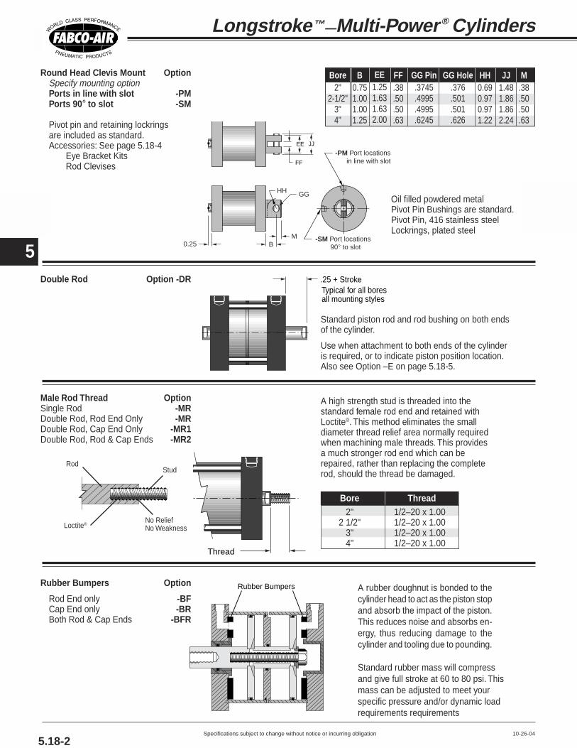
Specifications subject to change without notice or incurring obligation
4
5
5.18-210-26-04
Longstroke™—Multi-Power ® Cylinders
EE
0.25
JJ
FF
-PM Port locations in line with slot
BM -SM Port locations
90° to slot
HH GG
Male Rod Thread OptionSingle Rod -MRDouble Rod, Rod End Only -MRDouble Rod, Cap End Only -MR1Double Rod, Rod & Cap Ends -MR2
A high strength stud is threaded into thestandard female rod end and retained withLoctite®. This method eliminates the smalldiameter thread relief area normally requiredwhen machining male threads. This providesa much stronger rod end which can berepaired, rather than replacing the completerod, should the thread be damaged.
Double Rod Option -DR
Standard piston rod and rod bushing on both endsof the cylinder.
Use when attachment to both ends of the cylinderis required, or to indicate piston position location.Also see Option –E on page 5.18-5.
Rubber Bumpers Option
Rod End only -BFCap End only -BRBoth Rod & Cap Ends -BFR
A rubber doughnut is bonded to thecylinder head to act as the piston stopand absorb the impact of the piston.This reduces noise and absorbs en-ergy, thus reducing damage to thecylinder and tooling due to pounding.
Standard rubber mass will compressand give full stroke at 60 to 80 psi. Thismass can be adjusted to meet yourspecific pressure and/or dynamic loadrequirements requirements
Rubber Bumpers
Thread
RodStud
Loctite®No ReliefNo Weakness
.25 + StrokeTypical for all bores all mounting styles
Bore Thread2" 1/2–20 x 1.00
2 1/2" 1/2–20 x 1.003" 1/2–20 x 1.004" 1/2–20 x 1.00
EE1.251.631.632.00
FF.38.50.50.63
GG Pin.3745.4995.4995.6245
HH0.690.970.971.22
JJ1.481.861.862.24
M.38.50.50.63
Bore2"
2-1/2"3"4"
GG Hole.376.501.501.626
B0.751.001.001.25
Oil filled powdered metalPivot Pin Bushings are standard.Pivot Pin, 416 stainless steelLockrings, plated steel
Round Head Clevis Mount OptionSpecify mounting optionPorts in line with slot -PMPorts 90° to slot -SM
Pivot pin and retaining lockringsare included as standard.Accessories: See page 5.18-4
Eye Bracket KitsRod Clevises

Specifications subject to change without notice or incurring obligation
4
5
5.18-310-26-04
Series MLR & MLS Option Specifications
Adjustable extend strokeOption -AS
Available all Bores.For strokes through 6"Full stroke adjustment is standard.
Note!To maintain operator safety featuresof this option, it is NOT available withmounting styles: -WR and -WFR.Use caution when mounting to avoidcreating pinch points.
Nonrotating Rod Option -NR
B + [ See Chart ]
Ported Baffle
Atmospheric Ventfor all extend/retractcombinations
Retract Port
No rodseal
Hex RodA stainless steel hex rod and a hexbroached bushing of SAE 660 bearingbronze replaces the standard roundrod and bushing.
A ported baffle is used so the pistonassembly can be retracted by the nextpiston back from the rod end. Thenormal rod head port becomes anatmospheric vent. The tolerance onrotation is ±1°.
The hex rod design does allow forsome torque loading on the shaft.However, torque loads that induce sideloading should be minimized for bestoverall life and performance.
Nonrotating Double Rod Option-NRDR
A combination of the Options –NRand –DR as shown above. The rodend rod is Hex and the cap end rodis round. The ported baffles are
High Flow Vents Option -HF The atmospheric vent in the baffleis cut larger to provide less resis-tance to the air flow.
included and the “Dimension B” adjust-ments shown for Option –NR must bemade. Extend piston areas must also bereduced by the rod area.
Use when higher cycle speeds arerequired.
Viton Seals Option -V Use for elevated temperatures(–15° to + 400°F) or compatibilitywith exotic media.
Consult engineering for compatibilityinformation.
BC + (2 x Stroke)
BD + StrokeBE + Stroke
BB Diameter
BFStroke adjustmentper revolution
BADiameter
3/8 NPT Ports in Heads Option -P38
No. of TotalAvailable Ported No. of
Combinations Baffles Stages2 – 1 1 23 – 1 1 33 – 2 2 34 – 1 1 44 – 2 2 44 – 3 3 4
Add toDimension “B” Hex
for each RodBore Port Ported Baffle Flat
2" 1/4 NPT .50" .75"2-1/2" 1/4 NPT .50" .75"
3" 1/4 NPT .50" .75"4" 1/4 NPT .50" 1.00"
+ (2 x Stroke)
+ Stroke
Bore 2" 2-1/2" 3" 4"
BA 1.50 1.50 1.50 2.00
BB 2.00 2.00 2.00 2.00
BC 1.65 1.65 1.65 1.42
BD 0.75 0.75 0.75 0.50
BE 0.75 0.75 0.75 0.75
BF .063 .063 .063 .063
See complete description on page 5.9.
Use 3/8 NPT ports for higher flows,air over oil systems, etc.
See page 5.18 for Dimension “B”.

Specifications subject to change without notice or incurring obligation
4
5
End Lug Mount Kit
(Number of stages timesstroke) + Dim. XAAH
AOAT (Number of stages timesstroke) + Dim. SA
AO
SW1
4
2
W/2 S/23
AB 6 Holes
Kit includes:2 Brackets and4 bolts for attachingthe brackets to thecylinder heads.
Materials:Brackets, steel, platedScrews, steel, black oxide
AB.41.41.53.53
AH1.632.002.132.63
AO.44.44.56.56
AT.25.25.38.38
Bore2"
2-1/2"3"4"
S1.752.252.753.50
W2.503.003.504.50
Kit No.EL-20EL-25EL-30EL-40
XA 3 stage
4.834.895.145.14
XA 4 stage
5.685.745.995.99
XA 2 stage
3.984.044.294.29
SA 3 stage
4.895.015.515.51
SA 4 stage
5.745.866.366.36
SA 2 stage
4.044.164.664.66
(Number of stages times stroke) + Dimension XE1
LH
EO1 (Number of stages times stroke) + Dimension SS1
TSUS
1
4
2
US/2 TS/2
3
EO1
SB 4 Holes
ST
(Number of stages times stroke) + Dim. XE2
LH
EO2(Number of stages
times stroke) + Dim. SS2
TSUS
1
4
2
US/2 TS/2
3
EO2
SB 4 Holes
ST
Kit includes:2 Brackets and4 bolts for attachingthe brackets to thecylinder heads.
Materials:Brackets, steel, platedScrews, steel, blackoxide
Rod Clevises
MI
J
P
E PinC
D F
L
MaterialsClevis and Stud: Steel, black oxidedPin: 416 Stainless SteelClips: Steel, plated
Eye Bracket Kits mate with Option -PM or -SM and Rod ClevisN L M
IJ
H
BC
AK
E
D
MaterialsBracket: High strength Zinc die castingBushings: Oil filled powdered metalScrews: 4, Steel, plated or black oxided
A2.502.002.501.50
D.36.47.58.30
E.376.501.626
.3135
H.31.38.38.25
I1.131.501.630.94
Part #EM-321EM-521EM-1221EM-121
J1.692.252.631.38
K2.001.381.751.13
L0.560.751.000.44
M0.811.131.100.69
Bore2"
2-1/2", 3"4"
Rod Clevis RC-56
B2.502.002.251.50
C2.001.381.501.13
N5/16-18x1.00FHSCS5/16-18x1.00FHSCS5/16-18x1.00FHSCS
1/4-20X.75 FH(#12)MS
10-30-04
Position #1 Position #2
SB.41.41.53.53
Bore2"
2-1/2"3"4"
EO1.50.50.56.56
LH1.632.002.132.63
Kit No.SL-20SL-25SL-30SL-40
SS1 3 stage
3.513.774.394.39
SS1 4 stage
4.364.625.245.24
SS1 2 stage
2.662.923.543.54
XE1 3 stage
4.144.274.584.58
XE1 4 stage
4.995.125.435.43
XE1 2 stage
3.293.423.733.73
SS2 3 stage
3.273.272.142.14
SS2 4 stage
4.124.122.992.99
SS2 2 stage
2.422.421.291.29
XE2 3 stage
4.024.023.453.45
XE2 4 stage
4.874.874.304.30
XE2 2 stage
3.173.172.602.60
ST.25.25.38.38
TS3.754.254.755.50
US4.505.005.886.63
EO20.500.631.191.19
C1.00
D.32
E PIN.3120
F1.21
I1.31
Part #RC-56
J1.69
L.61
M.63
P1/2-20x.62
Mating Eye BktEM-121
Bore2", 2-1/2", 3" & 4"
5.18-4
Side Lug Mount Kit – Brackets may be mounted in two different positions as shown –
Longstroke™—Multi-Power ® Cylinders
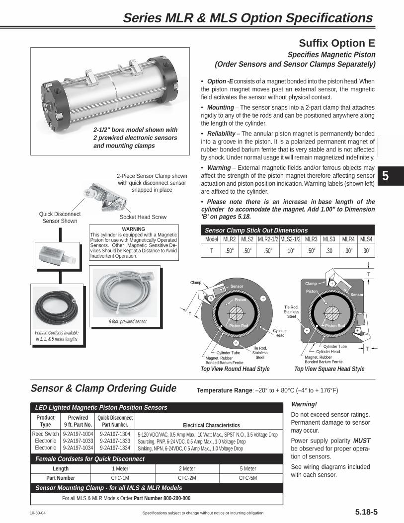
Specifications subject to change without notice or incurring obligation
4
5
Sensor & Clamp Ordering GuideWarning!
Do not exceed sensor ratings.Permanent damage to sensormay occur.
Power supply polarity MUSTbe observed for proper opera-tion of sensors.
See wiring diagrams includedwith each sensor.
Temperature Range: –20° to + 80°C (–4° to + 176°F)
10-30-04
Electrical Characteristics
5-120 VDC/VAC, 0.5 Amp Max., 10 Watt Max., SPST N.O., 3.5 Voltage DropSourcing, PNP, 6-24 VDC, 0.5 Amp Max., 1.0 Voltage DropSinking, NPN, 6-24VDC, 0.5 Amp Max., 1.0 Voltage Drop
Quick DisconnectPart Number.
9-2A197-13049-2A197-13339-2A197-1334
Prewired9 ft. Part No.
9-2A197-10049-2A197-10339-2A197-1034
ProductType
Reed SwitchElectronicElectronic
LED Lighted Magnetic Piston Position Sensors
For all MLS & MLR Models Order Part Number 800-200-000
Length 1 Meter 2 Meter 5 Meter
Part Number CFC-1M CFC-2M CFC-5M
Sensor Mounting Clamp - for all MLS & MLR Models
Female Cordsets for Quick Disconnect
Series MLR & MLS Option Specifications
2-1/2" bore model shown with2 prewired electronic sensorsand mounting clamps
Female Cordsets availablein 1, 2, & 5 meter lengths
9 foot prewired sensor
2-Piece Sensor Clamp shownwith quick disconnect sensor
snapped in place
Socket Head ScrewQuick DisconnectSensor Shown
WARNINGThis cylinder is equipped with a MagneticPiston for use with Magnetically OperatedSensors. Other Magnetic Sensitive De-vices Should be Kept at a Distance to AvoidInadvertent Operation.
Suffix Option ESpecifies Magnetic Piston
(Order Sensors and Sensor Clamps Separately)
Model MLR2 MLS2 MLR2-1/2 MLS2-1/2 MLR3 MLS3 MLR4 MLS4
T .50" .50" .50" .10" .50" .30 .30" .30"
Sensor Clamp Stick Out Dimensions
Sensor
Magnet, Rubber Bonded Barium Ferrite
Tie Rod, Stainless
Steel
Cylinder HeadCylinder Tube
Piston Rod
Piston
Clamp
T
T
Sensor
Magnet, Rubber Bonded Barium Ferrite
Tie Rod, Stainless
Steel
Cylinder Head
Cylinder Tube
Piston Rod
Piston
Clamp
T
Top View Round Head Style Top View Square Head Style
5.18-5
• Option -E consists of a magnet bonded into the piston head. Whenthe piston magnet moves past an external sensor, the magneticfield activates the sensor without physical contact.
• Mounting – The sensor snaps into a 2-part clamp that attachesrigidly to any of the tie rods and can be positioned anywhere alongthe length of the cylinder.
• Reliability – The annular piston magnet is permanently bondedinto a groove in the piston. It is a polarized permanent magnet ofrubber bonded barium ferrite that is very stable and is not affectedby shock. Under normal usage it will remain magnetized indefinitely.
• Warning – External magnetic fields and/or ferrous objects mayaffect the strength of the piston magnet therefore affecting sensoractuation and piston position indication. Warning labels (shown left)are affixed to the cylinder.
• Please note there is an increase in base length of thecylinder to accomodate the magnet. Add 1.00" to Dimension'B' on pages 5.18.

6
Specifications subject to change without notice or incurring obligation
BP 21/2 x 2 - FT
BA 21/2 x 2 - FT
6.1
Multi-Power® Boosters
�����������������
��
PistonSeals
Piston
Baffle
CenterShaft
Air into MultiplePistons for Power
Stroke. 30 psi Minimum Input
PilotWasher
PistonStop
Cap EndPlug
Check ValveNot Furnished
High (Boosted) Pressure Output 500 psi Maximum
Check Valve Not Furnished
Pressurized Input to Boosterand to Reset (30 psi Minimum)
DrivingEnd
OutputEnd
Nut
Piston
AtmosphericVent
TubeSeal
BaffleSeal
��������������
����
PistonSeals
Piston
Baffle
CenterShaft
BaffleSeal
Air into MultiplePistons for Power
Stroke. 30 psi Minimum Input
Air into SinglePiston for Reset
Stroke
PilotWasher
PistonStop
Cap EndPlug
Check ValveNot Furnished
High (Boosted) Pressure Output 500 psi Maximum
Check Valve Not Furnished
Gravity Feed Oil or FluidAtmospheric Pressure: Air or Gas
DrivingEnd
OutputEnd
Nut
Piston
TubeSeal
8-22-01
Fabco-Air Multi-Power® Boosters pro-vide a convenient, low cost way of addingthe control, rigidity, and power of hydrau-lics to an air powered machine. Boostersuse shop air to raise the pressure of an-other gas or liquid. They are compact, andversatile finding use in numerous of appli-cations such as clamping, shearing, press-ing, crimping, bending, testing, and manymore.
When relatively small volumes of high-pressure fluid are called for intermittently,boosters show obvious advantages overcontinuously running hydraulic systems.
For applications where high pressuremust be maintained for prolonged times,boosters are ideal. After the boosterstrokes, there is no further energy inputrequired and no heat build up.
A booster can be mounted in almost
This series is built for use on systems in which the input to the booster will begravity fed (no pressure) fluid or atmospheric pressure gas. It requires a 4-way airvalve for operation. Porting is provided on the unit for the multiple piston powerstroke and the single piston reset stroke. (See example circuits on page 6.11.)
Atmospheric Pressure Inlet to Booster: Series BA Pressurized Inlet to Booster: Series BP
any convenient location, and most of itscontrol valves are installed in the low-pressure circuit where lower cost compo-nents save costs over hydraulics.
The input is shop air, or any com-patible gas, up to 150 psi; the outputcan be oil, liquid, air, or gas pressur-ized to 500 psi maximum.
By selecting the proper combination ofbore size, stroke, power factor and regu-lating the input air pressure, the exactoutput pressure and required volumecan be achieved and maintained.
Since it is a basic booster withoutcontrols built-in, it can be adapted andcontrolled to perform a wide variety ofapplications. Fabco-Air boosters are notlimited to cylinder applications. They maybe used wherever a small volume of high-pressure media is required.
This series is built for use on systems in which the input to the booster will bepressurized fluid or gas. It requires a 3-way air valve for operation. Porting isprovided on the unit for the power stroke only. When power stroke air is removed,the pressurized booster input will reset the pistons. (See example circuits on page6.9 and 6.10.)
• Low initial cost: Boosters can eliminatethe need for costly hydraulic systems.
• Low energy cost: Boosters hold pres-sure indefinitely without energy loss.
Save space: Boosters can usually bemounted directly on the machine unlikepumping units which are large and bulky.
• Smooth power: Boosters give the workcylinder the rigid, smooth, controlled mo-tion of hydraulics.
• Safe: Boosters can be completely airoperated to function safely in a potentiallyhazardous environment.
• Clean: Air to air boosters have no oil orliquid to contaminate the surroundings.
• 2 Ports in boost chamber for inlet/outlet.Note: Check valves are not included.
• Internally lubricated Buna-N seals(-25° to + 250°F)
• U-Cup and O'Ring seals on thebooster piston
• Heavy duty, corrosion resistantconstruction
• Aluminum tubing: Hard anodized ID,Clear anodized OD
• Black anodized heads.
• Plated tie rods and nuts.
• Outputs of 4.9 or 12.5 cu. in. perinch of stroke
• Standard strokes: 1" increments through 6"
• 1.9 through 4.8 power factors

6
Specifications subject to change without notice or incurring obligation 6.2
How to Order1. Specify Series and Bore2. Specify Stroke3. Specify stages (Power Factor)4. Specify Mounting5. Specify Option(s)
3-19-03
Examples:BA 21/2 x 2 – 3 – FF – PA2BA Series, 21/2" Bore, 2" Stroke, 3 Stage (2.8 PF), OutputEnd Flange Mounting, All Ports Position#2 (See page 6.6).
BP 4 x 6 – 5 – WFBP Series, 4" Bore, 6" Stroke, 5 Stage (4.8 PF), ExtendedTie Rods (Output End Only) Mounting.
Sizing Guide and How to Order
Description Specify See PageViton Seals (-15° to +400°F) -V 6.5Rubber Bumpers, Driving End -BR 6.5Adjustable Extend Stroke -AS 6.6
6" Stroke maximum. Full strokeadjustment is standard.
1/2 NPT Ports in Heads ‡ 6.5Output End -TFDriving End -TRBoth Ends -TFR
Extend Port Bushing 6.53/8 NPT Output End -EF38
Driving End -ER38Both Ends -EFR38
1/2 NPT Output End -EF12Driving End -ER12Both Ends -EFR12
High Flow Vents -HF 6.6Port Positions (PA2, PA3, etc.) See page 6.6
Any port or vent not specified will bein position shown on page 6.3
Magnetic Piston ‡ -E 6.7for Reed Switches and Electronic Sensors(Order Sensors separately)
Piston Rod Driving End -P 6.8Pneumatic Continuous Cycling -L 6.8Male Rod Thread -MR 6.8
‡ Note: Additional cylinder length required:for Option -E add 1" to driving end stage only;for 1/2 NPT Ports Option see page 6.5.
Options
Model Number Code
x2-1/2 2 FFBA
SeriesBABP
– PA2
StandardStrokes
123456
OptionalStrokesAny other
strokethrough 12"
–
Bore2-1/2"
4"
Mounting
Output End Flange – Fabco Pattern . . . . . . . . . . –FFOutput End Flange – NFPA (MF1) Pattern . . . . –FFADriving End Flange – Fabco Pattern . . . . . . . . . . –RFDriving End Flange – NFPA (MF2) Pattern . . . –RFA
Foot . . . . . . . . . . . . . . . . . . . . . . . . . . . . . . . –FT
Extended Tie RodsOutput End only . . . . . . . . . . . . . . . . . –WFDriving End only . . . . . . . . . . . . . . . . . –WRBoth Ends . . . . . . . . . . . . . . . . . . . . . –WFR
3
Stages2
3
4
5
SeePower Factor
informationabove
–
Sizing GuideRequired Volume/Inch Required Required
Number of Volume/Inch of Stroke Volume/Inch Volume/InchStages Theoretical of Stroke Maximum of Stroke
Bore (Pistons) Power Factor In3 Gallons In3 psi In3
2 1.9 9.7 1502-1/2 3 2.8 4.9 .021 14.5 150 4.5
4 3.7 19.3 1355 4.6 24.1 105
2 1.9 25.1 1504 3 2.9 12.5 .054 37.6 150 11.8
4 3.8 50.1 1255 4.8 62.6 100
Output Input Reset Power AirDisplacement Power Air for Series BA

6
Specifications subject to change without notice or incurring obligation6.3
Multi-Power® Boosters
T T
RRA
UAOThd
NHex Nut4 Places
Driving End
Q 1
2
3
4
S E
S
C
E
BD
F
Driving EndPort Pos. 1
Output EndPort Pos. 1 & 3
T T
RRA
U
NHex Nut4 Places
Driving End
AOThd
Q1
2
3
4
SE
S
CCE
BBDD
FF
Driving EndPort Pos. 1
Output EndPort Pos. 1 & 3
VV
T T
RR
A
NHex Nut4 PlacesBoth EndsALLModels
WF WR
AOThd
Q1
2
3
4
SE
SE
Driving EndPort Pos. 1
Output EndPort Pos. 1 & 3
Dimensions (inches)
3-19-03
-WF Extended Tie Rod Mount, Output End Only-WR Driving End Only-WFR Both Ends
-FF Front Face Mount;Output End Rectangular FlangeFabco mounting pattern
-FFA Front Face Mount;Output End Rectangular FlangeNFPA (MF1) mounting pattern
Bore
2-1/2or4
Stages2345
Series BA3.914.765.616.46
Series BP3.414.265.115.96
Dimension Y‡
To order Extended Tie Rod MountSpecify Suffix
Output End Only -WFDriving End Only -WRBoth Ends -WFRIf a non-standard extension is required,specify by adding the required length tothe suffix.
e.g. If -WF length required is 2.5"Specify -WF2.5"
Bore2-1/2
4
B3.635.00
ADim. A= (No. stages x stroke) + Y‡
See Y‡ chart above
C2.383.75
D4.256.00
E3.005.00
F.34.41
N9/163/4
P3.695.50
Q1/4 NPT1/4 NPT
R.75.75
S2.313.50
T.31.31
U.38.50
V.33.43
X.44.63
Z.56.88

6
Specifications subject to change without notice or incurring obligation 6.4
T T
RRA
U
AOThd
NHex Nut4 Places
Output End
Q1
2
3
4
SE
S
C
E
BD
F
Driving EndPort Pos. 1
Output EndPort Pos. 1 & 3
T T
RRA N
Hex Nut4 Places
Output EndU
AOThd
Q 1
2
3
4
SE
S
CCE
BBDD
FF
Driving EndPort Pos. 1
Output EndPort Pos. 1 & 3
XX
T T
RR
A
NHex Nut4 PlacesBoth Ends
.25Z Z
Q 1
2
3
4
SP
S
FO
HT
HC
E
F
Driving EndPort Pos. 1
Output EndPort Pos. 2 & 4
8-24-01
-FT Foot Mount
-RF Rear Face Mount;Driving End Rectangular FlangeFabco mounting pattern
-RFA Rear Face Mount;Driving End Rectangular FlangeNFPA (MF2) mounting pattern
AO3/8-161/2-13
BB3.885.44
CC2.193.32
DD4.506.38
FF.34.41
FO4.386.38
HC1.752.75
HT3.255.25
WF1.301.40
WR1.301.40
Mounting Styles with Dimensions
Stages Theoretical Series BA Series BP BA or BP Internally LubricatedBore (Pistons) Power Factor Zero Stroke Zero Stroke Per Inch of Stroke Buna-N Viton
2 1.9 46 44 12 BA/BP21/2-2SK BA/BP21/2-2SKV2-1/2 3 2.8 55 53 17 BA/BP21/2-3SK BA/BP21/2-3SKV
4 3.7 64 62 23 BA/BP21/2-4SK BA/BP21/2-4SKV5 4.6 73 71 30 BA/BP21/2-5SK BA/BP21/2-5SKV
2 1.9 111 105 17 BA/BP4-2SK BA/BP4-2SKV4 3 2.9 130 124 24 BA/BP4-3SK BA/BP4-3SKV
4 3.8 149 142 32 BA/BP4-4SK BA/BP4-4SKV5 4.8 166 160 41 BA/BP4-5SK BA/BP4-5SKV
Approximate Weight, Oz. Universal Seal Kits
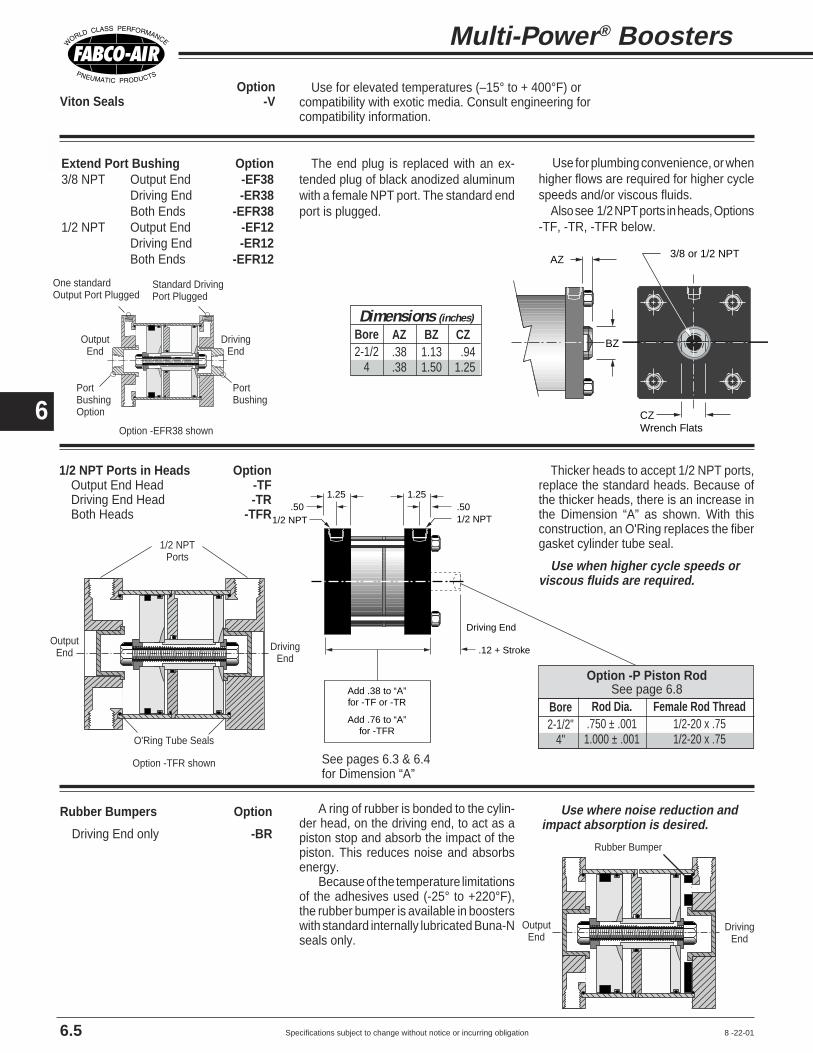
6
Specifications subject to change without notice or incurring obligation
OptionViton Seals -V
Use for elevated temperatures (–15° to + 400°F) orcompatibility with exotic media. Consult engineering forcompatibility information.
Extend Port Bushing Option3/8 NPT Output End -EF38
Driving End -ER38Both Ends -EFR38
1/2 NPT Output End -EF12Driving End -ER12Both Ends -EFR12
The end plug is replaced with an ex-tended plug of black anodized aluminumwith a female NPT port. The standard endport is plugged.
AZ
BZ
3/8 or 1/2 NPT
CZWrench Flats
1/2 NPT Ports in Heads OptionOutput End Head -TFDriving End Head -TRBoth Heads -TFR
Thicker heads to accept 1/2 NPT ports,replace the standard heads. Because ofthe thicker heads, there is an increase inthe Dimension “A” as shown. With thisconstruction, an O'Ring replaces the fibergasket cylinder tube seal.
Use when higher cycle speeds orviscous fluids are required.
.12 + Stroke
1/2 NPT
Add .38 to “A” for -TF or -TR
Add .76 to “A” for -TFR
.501.25
.501.25
1/2 NPT
Driving End
Rubber Bumpers Option
Driving End only -BR
A ring of rubber is bonded to the cylin-der head, on the driving end, to act as apiston stop and absorb the impact of thepiston. This reduces noise and absorbsenergy.
Because of the temperature limitationsof the adhesives used (-25° to +220°F),the rubber bumper is available in boosterswith standard internally lubricated Buna-Nseals only.
Bore2-1/2
4
AZ.38.38
Dimensions (inches)
BZ1.131.50
CZ.94
1.25
Use for plumbing convenience, or whenhigher flows are required for higher cyclespeeds and/or viscous fluids.
Also see 1/2 NPT ports in heads, Options-TF, -TR, -TFR below.
Use where noise reduction andimpact absorption is desired.
6.5
Multi-Power® Boosters
O'Ring Tube Seals
Option -TFR shown
Rubber Bumper
8 -22-01
DrivingEnd
OutputEnd
DrivingEnd
OutputEnd
1/2 NPTPorts
Bore2-1/2"
4"
Rod Dia..750 ± .001
1.000 ± .001
Female Rod Thread1/2-20 x .751/2-20 x .75
Option -P Piston RodSee page 6.8
PortBushing
One standardOutput Port Plugged
Standard DrivingPort Plugged
PortBushingOption
DrivingEnd
OutputEnd
Option -EFR38 shown
See pages 6.3 & 6.4for Dimension “A”

6
Specifications subject to change without notice or incurring obligation
MountFT
Output Ports Specify2&4 Standard1&3 -PR21&2 -PR31&4 -PR42&3 -PR53&4 -PR6
8-24-01
Adjustable Extend StrokeFor strokes through 6" Option -ASFull stroke adjustment is standard.
Note!To maintain operator safety featuresof this option, it is NOT available withmounting styles: -WR and -WFR.Use caution when mounting to avoidcreating pinch points.
Dial-A-Stroke® provides a rugged and precision adjustment of the extendstroke of the cylinder. The stop tube, adjustment nut with skirt, andminimum clearances combine to eliminate pinch points, thus providingoperator safety. Note! Use caution when mounting to avoid creating pinchpoints with other parts of your machine design.
The stop tube is blue anodized aluminum, the adjustment nut is black-ened steel with a black anodized aluminum skirt, and the nut stop is redanodized aluminum; all for corrosion resistance and appearance. Theadjustment nut, steel for long life, includes a lock screw with a plastic plugso that the adjustment nut can be locked in place without damaging thethreads. The nut stop is mounted on the end of the adjustment rod so thatthe nut cannot come off. The fine pitch threads on the adjustment rod andnut provide precision adjustment. Adjustment settings are simplified byconvenient scale markings applied to nut skirt and stop tube.
Nut Stop
Adjustment Rod with fine pitch thread
Adjustment Nut with Mating Fine Pitch Thread
1/2"Minimum Clearance when fully stroked
Adjustment Nut SkirtLock ScrewPlastic Plug
Stop TubeRod Bushing
Contact Surfaces totally enclosed
Note: Use caution when mounting to avoid creating pinch points
6.6
Option Specifications
High Flow Vents Option -HF The atmospheric vent in the baffle is cut largerto provide less resistance to the air flow.
Use when higher cycle speeds are required.
2 1/2" Bore = 1.90 + (2 x Stroke)4" Bore = 1.67 + (2 x Stroke)
.75 + Stroke
2.00 Diameter
.063Stroke adjustmentper revolution
2-1/2" Bore =1.50 Dia.4" Bore = 2.00 Dia.
2 1/2" Bore =1.00 + Stroke
4" Bore =.75 + Stroke Driving End
Port Positions Option(Facing Output End, see Drawings on pages 6.3 & 6.4)All Ports with Mounts: -FF, -FFA,
-RF, -RFA, -WF, -WR, -WFROutput Vent Driving
1&3 1 1 Standard2&4 2 2 -PA21&3 3 3 Rotate Standard2&4 4 4 Rotate -PA2
All Ports with Mount -FTOutput Vent Driving
2&4 1 1 Standard1&3 2 2 -PA22&4 3 3 -PA31&3 4 4 -PA4
For all other combinations of port locations specifyeach port location per the chart on the right. Any portor vent not specified will be in position shown onpages 6.3 & 6.4.
Atmospheric Vent orPorted Baffle Port Specify
1 Standard2 -PB23 -PB34 -PB4
Driving Port Specify
1 Standard2 -PC23 -PC34 -PC4
Mounts: -FF, -FFA,-RF, -RFA, -WF, -WR, -WFR
Output Ports Specify1&3 Standard2&4 -PR21&2 -PR31&4 -PR42&3 -PR53&4 -PR6
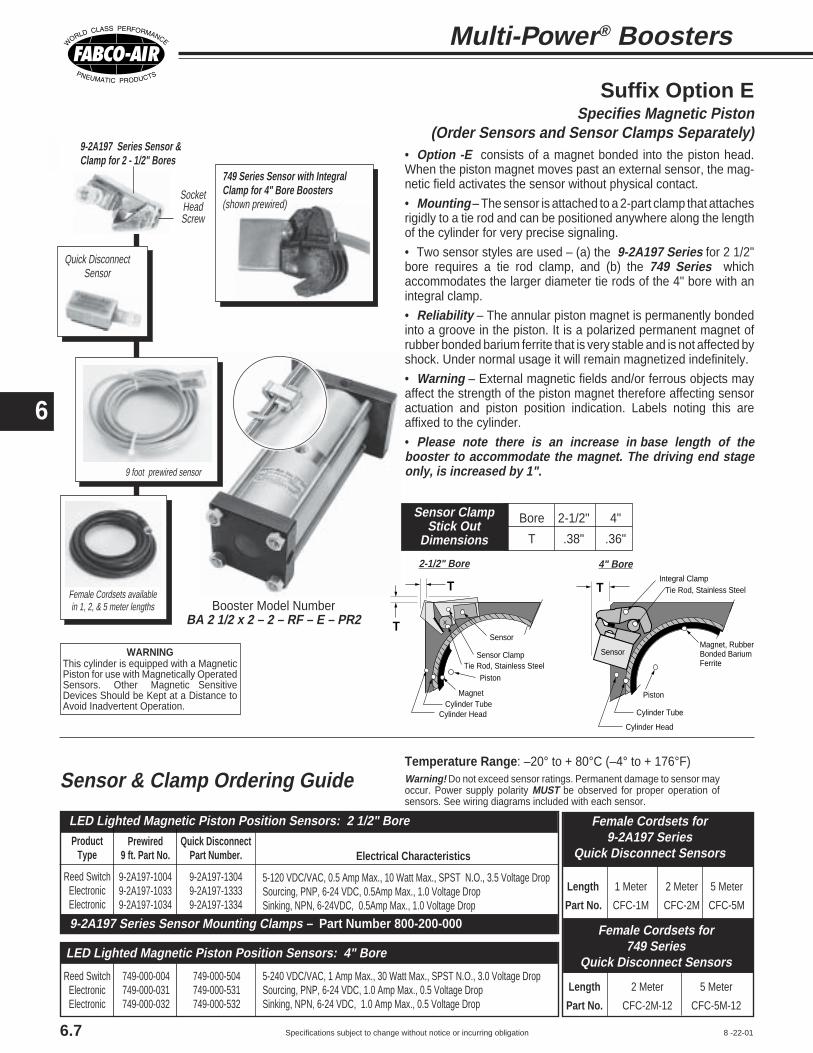
6
Specifications subject to change without notice or incurring obligation
Electrical Characteristics
5-120 VDC/VAC, 0.5 Amp Max., 10 Watt Max., SPST N.O., 3.5 Voltage DropSourcing, PNP, 6-24 VDC, 0.5Amp Max., 1.0 Voltage DropSinking, NPN, 6-24VDC, 0.5Amp Max., 1.0 Voltage Drop
Quick DisconnectPart Number.
9-2A197-13049-2A197-13339-2A197-1334
Prewired9 ft. Part No.
9-2A197-10049-2A197-10339-2A197-1034
ProductType
Reed SwitchElectronicElectronic
LED Lighted Magnetic Piston Position Sensors: 2 1/2" Bore
5-240 VDC/VAC, 1 Amp Max., 30 Watt Max., SPST N.O., 3.0 Voltage DropSourcing, PNP, 6-24 VDC, 1.0 Amp Max., 0.5 Voltage DropSinking, NPN, 6-24 VDC, 1.0 Amp Max., 0.5 Voltage Drop
749-000-504749-000-531749-000-532
749-000-004749-000-031749-000-032
Reed SwitchElectronicElectronic
9-2A197 Series Sensor Mounting Clamps – Part Number 800-200-000
LED Lighted Magnetic Piston Position Sensors: 4" Bore
749 Series Sensor with IntegralClamp for 4" Bore Boosters(shown prewired)
• Option -E consists of a magnet bonded into the piston head.When the piston magnet moves past an external sensor, the mag-netic field activates the sensor without physical contact.
• Mounting – The sensor is attached to a 2-part clamp that attachesrigidly to a tie rod and can be positioned anywhere along the lengthof the cylinder for very precise signaling.
• Two sensor styles are used – (a) the 9-2A197 Series for 2 1/2"bore requires a tie rod clamp, and (b) the 749 Series whichaccommodates the larger diameter tie rods of the 4" bore with anintegral clamp.
• Reliability – The annular piston magnet is permanently bondedinto a groove in the piston. It is a polarized permanent magnet ofrubber bonded barium ferrite that is very stable and is not affected byshock. Under normal usage it will remain magnetized indefinitely.
• Warning – External magnetic fields and/or ferrous objects mayaffect the strength of the piston magnet therefore affecting sensoractuation and piston position indication. Labels noting this areaffixed to the cylinder.
• Please note there is an increase in base length of thebooster to accommodate the magnet. The driving end stageonly, is increased by 1".
9-2A197 Series Sensor &Clamp for 2 - 1/2" Bores
SocketHeadScrew
Suffix Option ESpecifies Magnetic Piston
(Order Sensors and Sensor Clamps Separately)
Integral Clamp
Piston
Magnet, RubberBonded BariumFerrite
Tie Rod, Stainless Steel
Cylinder Head
Cylinder Tube
T
SensorWARNINGThis cylinder is equipped with a MagneticPiston for use with Magnetically OperatedSensors. Other Magnetic SensitiveDevices Should be Kept at a Distance toAvoid Inadvertent Operation.
8 -22-01
Sensor & Clamp Ordering Guide Warning! Do not exceed sensor ratings. Permanent damage to sensor mayoccur. Power supply polarity MUST be observed for proper operation ofsensors. See wiring diagrams included with each sensor.
Length 1 Meter 2 Meter 5 Meter
Part No. CFC-1M CFC-2M CFC-5M
Female Cordsets for9-2A197 Series
Quick Disconnect Sensors
Female Cordsets for749 Series
Quick Disconnect Sensors
Length 2 Meter 5 Meter
Part No. CFC-2M-12 CFC-5M-12
4" Bore
Female Cordsets availablein 1, 2, & 5 meter lengths
2-1/2" Bore
Sensor Clamp
Piston
Magnet
Tie Rod, Stainless Steel
Cylinder HeadCylinder Tube
T
SensorT
9 foot prewired sensor
Booster Model NumberBA 2 1/2 x 2 – 2 – RF – E – PR2
Quick DisconnectSensor
Temperature Range: –20° to + 80°C (–4° to + 176°F)
6.7
Multi-Power® Boosters
Bore 2-1/2" 4"
T .38" .36"
Sensor ClampStick Out
Dimensions

6
Specifications subject to change without notice or incurring obligation8-22-01
Option Specifications
6.8
Male Rod Thread Option -MR
A high strength stud is threaded into thestandard female rod end (see Option -Pabove) and retained with Loctite®. Thismethod eliminates the small diameterthread relief area normally required whenmachining male threads. This provides a
much stronger rod end which can be re-paired, rather than replacing the completerod, should the thread be damaged.
Use in conjunction with Option -Pabove.
A piston rod is incorporated in thedriving end. Two limit valves are mountedon the driving end head and a piston rodguide and limit valve actuators are at-tached to the piston rod. The limit valvescontrol a 3 or 4 way control valve (notincluded, see Section 11) which in turncontrols the booster. When the system is“powered up” the booster strokes, raisingthe fluid pressure in the output end. Whenit fully strokes, a limit valve is actuated,reversing the booster, resetting it. When itis fully reset, the other limit valve is actuatedshifting the control valve for another powerstroke. This cycle continues until the outputpressure reaches the desired level. Thebooster then stalls out and holds thatpressure until some of the fluid is used.The booster then resumes cycling untiloutput fluid again reaches desired pres-sure and the booster stalls out. This cyclingwill continue as long as the system is“powered up.”
During the stall mode there is no en-ergy used, making the air powered boosteran extremely efficient and quiet method ofmaintaining that high pressure. A hydraulic
power unit, for instance, requirescontinuous energy input.
Because of the piston rod, the PowerFactors change slightly as shown in thechart below. A typical circuit and sizinginstructions are shown in example 1 onpage 6.9.
Use when the application requirespumping action (e.g. keeping a surge tankat high pressure for a test fixture) and/orthere is no electricity involved (e.g. anexplosive atmosphere). Also see Option-E on page 6.7 for electronic position sen-sors.
# Stages TheoreticalBore (Pistons) Power Factor
2 1.82-1/2 3 2.7
4 3.65 4.5
2 1.94 3 2.8
4 3.75 4.7
Piston Rod onDriving End Option -P
H + Stroke
L Wrench Flats
G
K Thread
M J
AA
BB
View A–A
View B–B
PneumaticContinuous Cycling Option -L
For details on the limit valves,which are included,see MSV-2 on page 13.5
Provisions for operator protectionare always the full responsibilityof the user.
A piston rod is incorporated in thedriving end. Because of the piston rodarea the Power Factor changes slightly.Use the Power Factors charted above forOption -L.
Bore2-1/2
4
G.19.19
J ± .0021.1271.502
L5/87/8
H.50.50
K1/2-20 x .751/2-20 x .75
M ± .0010.7501.000
Use for booster position indication.
1.00
Stud: 1/2 - 20No reliefNo weakness
Rod
Loctite®

6
Specifications subject to change without notice or incurring obligation6.9
Multi-Power® Boosters
Regulated Supply ControlsFinal Output Pressure of Booster
3-Way Control Valve
Cycle On/OffValve
SystemSupply
OutputEnd
BoostedPressureOutput
GageCheckValve
Storage TankAbsorbsPulses
System Supply
BP Series Booster withOption “L” Limit Valves
CheckValve
Driving End
8-24-01
To size an Air to Air booster Boyle's Law must be usedbecause air is compressible. Boyle's Law states: “When thetemperature of a confined gas remains constant, the volumevaries inversely as its absolute pressure.”
This can be stated mathematically as a simple equation:initial absolute pressure x initial volume = final absolutepressure x final volume or P1 x V1 = P2 x V2
Absolute pressure (psia) = gauge pressure (psig) + atmo-spheric pressure (14.7 psi).
Consult your distributor or Fabco-Air Engineering forassistance with booster sizing.
EXAMPLE 1: Pump cycle, Air to Air BoosterRequired output = 100 cu. in. per minute @ 250 psiAvailable air pressure = 70 psi
Input Air Usage, Pump Cycle (See Example 1 above; Model BP 2-1/2 x 4 - 4, 20 stroke/min. @ 70 psi)
Solution: Power = Required Pressure psig = 250Available Pressure psig 70
= 3.6 Minimum Required Power FactorChoose either: 2-1/2" Bore – 4 Stageor 4" Bore – 4 Stage (See Sizing Guide on page 6.2)
Solution (2-1/2" Bore): Volume - using Boyle's LawV1 (Initial Volume) = 4.9 cu. in./in.P1 (Initial Pressure) = 70 + 14.7 = 84.7P2 (Final Pressure) = 250 + 14.7 = 264.7V2 (Final Volume) = unknown
V2 = P1 x V1 = 84.7 x 4.9 = 1.5 cu. in./in. @250 psigP2 264.7
On the basis of 20 strokes/minute (typical average)
Booster stroke = Required Vol/min.vol/in. stroke x strokes/min
Booster stroke = 100 = 3.3 in. 1.5 x 20
Model Choice: BP2-1/2 x 4 - 4
Alternate Solution (4" Bore): Volume - using Boyle's LawV1 (Initial Volume) = 12.6 cu. in./in.P1 (Initial Pressure) = 70 + 14.7 = 84.7P2 (Final Pressure) = 250 + 14.7 = 264.7V2 (Final Volume) = unknown
V2 = P1 x V1 = 84.7 x 12.6 = 4.0 cu. in./in. @250 psigP2 264.7
On the basis of 20 strokes/minute (typical average)
Booster stroke = Required Vol/min.vol/in. stroke x strokes/min
Booster stroke = 100 = 1.25 in. 4.0 x 20
Model Choice: BP4 x 2 - 4
Solution: Pressure = Required Final Pressure = 250 = 67.6 psi regulated input requiredBooster Power Factor 3.7
Solution: Volume (CFM) = Input Volume/Inch Stroke x Stroke x CPM 1728 cu. in./cu.ft.
Input Volume/Inch Stroke = 19.3 (See Sizing Guide on page 6.2), Stroke = 4", CPM= 20
Volume = 19.3 x 4 x 20 = 1544 = 0.89 CFM @ 67.6 psi1728 1728
Converting Volume to SCFM: SCFM = CFM x psia = .89 x (67.6 + 14.7) = 5.0 SCFM required Atmosphere 14.7
○ ○ ○ ○ ○ ○ ○ ○ ○ ○ ○ ○ ○ ○ ○ ○ ○ ○ ○ ○ ○ ○ ○ ○ ○ ○ ○ ○ ○ ○ ○ ○

6
Specifications subject to change without notice or incurring obligation 6.10
Air-to-Air Sizing ( for Air-to-Oil Sizing See Page 6.11)
Regulated SupplyControls FinalOutput Pressureof Booster
3 way 2 Position Valve,Cycle to Boost Input to4 way before Operating4 way to Extend Cylinders
SystemInput
CheckValve
BP Series Booster
Driving EndOutput End
Gage Shows Booster Pressure
SystemInput 4 way 5 Port Valve,
2 Pressure Input,High Pressure Rating
WorkCylinders
SystemInput
4 way Control Valve
Regulated Supply
Controls FinalOutput Pressureof Booster
3 way Valve,Double Pilot
BP Series Booster
Driving EndOutput End
Gage Shows Booster Pressure
WorkCylinders
“RV” Sequence ValveAutomatically startsBooster when workload is reached
Pilot OperatedCheck Valve
8-24-01
EXAMPLE 2: One shot cycle, Air to Air Booster to extend cylinders withboosted (high) pressure. Application shown: 2 cylinders, 1-5/8" bore x 4" strokemust extend to full stroke at 145 psi, then retract at system (80 psi) pressure.
EXAMPLE 3: One shot cycle, Air to Air Booster to extend cylinders with low(system) pressure, then boost to high pressure.Application shown: 2 cylinders, 1-5/8" bore x 4" stroke must extend to fullstroke at system (80 psi) pressure, then apply full (145 psi) clamp load.Cylinders are to retract at system (80 psi) pressure.
Alternate Solution (4" Bore): Stroke = Required Volume = 45.8 = 3.6 in.Volume/Inch Stroke‡ 12.6‡
‡ For 4" Bore Volume per Inch of Stroke = 12.6 (See Sizing Guide on page 6.2)
Model Choice: BP4 x 4 - 2
Solution: Power = Required Pressure psig = 145Available Pressure psig 80
= 1.8 Minimum Required Power FactorChoose either: 2-1/2" Bore – 2 Stageor 4" Bore – 2 Stage (See Sizing Guide on page 6.2)
Solution: Volume - using Boyle's LawV1 (Initial Volume) = UnknownP1 (Initial Pressure) = 80 + 14.7 = 94.7P2 (Final Pressure) = 145 + 14.7 = 159.7V2 (Final Volume) = Volume required in cylinders, plus estimated volume in fittings and tubingV2 = 2.07 (area of 1-5/8" bore) x 4" (Stroke) x 2 (quantity) + 1.5 (estimate of fittings in this example) = 18.1 cu. in.
V1 = P2 x V2 = 159.7 x 18.1 = 30.5 cu. in.P1 94.7
Note! Add a recommended factor of 25% to 50% to allow for volumetric efficiencyand other losses: 30.5 x 150% = 45.8 cu. in. required in booster.
Solution (2-1/2" Bore): Stroke = Required Volume = 45.8 = 9.3 in. Volume/Inch Stroke‡ 4.9‡
‡For 2-1/2" Bore Volume per Inch of Stroke = 4.9 (See Sizing Guide on page 6.2)
Model Choice: BP2-1/2 x 10 - 2
Alternate Solution (4" Bore): Stroke = Required Volume = 18.6 = 1.5 in.Volume/Inch Stroke‡ 12.6‡
‡ For 4" Bore Volume per Inch of Stroke = 12.6 (See Sizing Guide on page 6.2)Model Choice: BP4 x 2 - 2
Solution: Power = Required Pressure psig = 145Available Pressure psig 80
= 1.8 Minimum Required Power FactorChoose either: 2-1/2" Bore – 2 Stageor 4" Bore – 2 Stage (See Sizing Guide on Page 6.2)
Solution: Volume - using Boyle's LawV1 (Initial Volume) = UnknownP1 (Initial Pressure) = 80 + 14.7 = 94.7P2 (Final Pressure) = 145 + 14.7 = 159.7V2 (Final Volume) = Volume required in cylinders, plus estimated volume in fittings and tubingV2 = 2.07 (area of 1-5/8" bore) x 4" (Stroke) x 2 (quantity) + 1.5 (estimate of fittings in this example) = 18.1 cu. in.
V1 = P2 x V2 = 159.7 x 18.1 = 30.5 cu. in.P1 94.7
Note! In this cycle, the volume of the cylinders and tubing may be deductedbecause it is a part of the final volume; thus, 30.5 - 18.1 = 12.4 cu.in.Add a recommended factor of 25% to 50% to allow for volumetric efficiency andother losses: 12.4 x 150% = 18.6 cu. in. required in booster.
Solution (2-1/2" Bore): Stroke = Required Volume = 18.6 = 3.8 in. Volume/Inch Stroke‡ 4.9‡
‡For 2-1/2" Bore Volume per Inch of Stroke = 4.9 (See Sizing Guide on page 6.2)
Model Choice: BP2-1/2 x 4 - 2○ ○ ○ ○ ○ ○ ○ ○ ○ ○ ○ ○ ○ ○ ○ ○ ○ ○ ○ ○ ○ ○ ○ ○ ○ ○ ○ ○ ○ ○ ○ ○ ○ ○ ○ ○
○ ○ ○ ○ ○ ○ ○ ○ ○ ○ ○ ○ ○ ○ ○ ○ ○ ○ ○ ○ ○ ○ ○ ○ ○ ○ ○ ○ ○ ○ ○ ○ ○ ○ ○ ○ ○ ○

6
Specifications subject to change without notice or incurring obligation
WorkCylinders
Driving EndOutput End
BA Series Booster
Regulated Supply Controls FinalOutput Pressure of Booster
Air/OilTank
Atmosphere
Gage
Pilot OperatedCheck Valve
4 Way Control Valve
Air/Oil Tank
Atmosphere
Regulated Supply Controls FinalOutput Pressure of Booster
4 Way Control Valve
Gage
Driving EndOutput End
Check Valve
Check Valve
Sensors
BA Series Booster withOption EMagnetic Pistonfor PistonPosition Sensing
8-24-01
To size an Air to Oil booster, Boyle's Law need not be taken into account because oil is considered an incompressible fluid.Consult Fabco-Air Engineering for fluid compatibility with standard internally lubricated Buna-N seals or optional Viton seals.
Air-to-Oil Sizing ( for Air-to-Air Sizing See Page 6.9 & 6.10)
6.11
EXAMPLE 5: Pump cycle, Air to Oil BoosterRequired output = 1000 cu. in./min. @ 250 psiAvailable air pressure = 70 psi
Solution: Power = Required Pressure psig = 145Available Pressure psig 80
= 1.8 Minimum Required Power FactorChoose either: 2-1/2" Bore – 2 Stageor 4" Bore – 2 Stage (See Sizing Guide on page 6.2)
Solution: Volume of Booster = Displacement of Cylinders + MarginDisplacement = Area of Bore x Stroke x Quantity of CylindersMargin = 25% Recommended to allow for losses and make-up fluidBooster Volume = [2.07 (area of 1-5/8" bore) x 4" (stroke) x 2 (quantity)]
x 125% (margin)= [16.6] x 1.25 = 20.8 cu. in.
Solution (2-1/2" Bore): Stroke = Required Volume = 20.8 = 4.3 in.Volume per Inch Stroke‡ 4.9‡
‡ For 2-1/2" Bore, Volume per Inch of Stroke = 4.9 (See Sizing Guide on page 6.2)Model Choice: BA2-1/2 x 5 - 2
Alternate Solution (4" Bore):
‡ For 4" Bore, Volume per Inch of Stroke = 12.6 (See Sizing Guide on page 6.2)
Model Choice: BA4 x 2 - 2
Stroke = Required Volume = 20.8 = 1.7 in.Volume per Inch Stroke‡ 12.6‡
Solution: Power = Required Pressure psig = 250Available Pressure psig 70
= 3.6 Minimum Required Power FactorChoose either: 2-1/2" Bore – 4 Stageor 4" Bore – 4 Stage (See Sizing Guide on page 6.2)
Solution (2-1/2" Bore): Stroke = Required Volume/Min = 1000 = 10.2 in.Volume per Inch Stroke‡ x CPM 4.9‡ x 20
‡ For 2-1/2" Bore, Volume per Inch of Stroke = 4.9 (See Sizing Guide on page 6.2)CPM = 20 (Typical average for Fabco-Air Air to Oil Booster)
Model Choice: BA2-1/2 x 11 - 4
Alternate Solution (4" Bore): Stroke = Required Volume/Min = 1000 = 3.97 in.Volume per Inch Stroke‡ x CPM 12.6‡ x 20
‡ For 4" Bore, Volume per Inch of Stroke = 12.6 (See Sizing Guide on page 6.2)CPM = 20 (Typical average for Fabco-Air Air to Oil Booster)
Model Choice: BA4 x 4 - 4
EXAMPLE 4: One shot cycle, Air to Oil BoosterApplication shown: 2 cylinders, 1-5/8" bore x 4" stroke must extend tofull stroke at 145 psi, then retract at system (80 psi) pressure.
Solution: Pressure = Required Final Pressure = 250 = 67.6 psi regulated input requiredBooster Power Factor 3.7
Solution: Volume (CFM) = [ Input Volume per Inch Stroke + Reset Volume per Inch Stroke] x Stroke x CPM 1728 cu.in. / cu.ft.
Input Volume per Inch Stroke = 19.3; Reset Volume per Inch Stroke = 4.5 (See Sizing Guide on page 6.2)Stroke = 11 CPM = 20
Volume = [19.3 + 4.5] x 11 x 20 = 23.8 x 0.127 = 3.03 CFM @ 67.6 psi1728
Converting Volume to SCFM:
Input Air Usage, Pump Cycle (See Example 5 above; Model BA 2-1/2 x 11 - 4, 20 stroke/min. @ 70 psi)
= CFM x psia = 3.03 x (67.6 + 14.7) = 17.0 SCFM requiredAtmosphere 14.7
○ ○ ○ ○ ○ ○ ○ ○ ○ ○ ○ ○ ○ ○ ○ ○ ○ ○ ○ ○ ○ ○ ○ ○ ○ ○ ○ ○ ○ ○ ○ ○ ○ ○ ○ ○ ○
○ ○ ○ ○ ○ ○ ○ ○ ○ ○ ○ ○ ○ ○ ○ ○ ○ ○ ○ ○ ○ ○ ○ ○ ○ ○ ○ ○ ○ ○ ○ ○ ○ ○ ○ ○ ○ ○ ○ ○
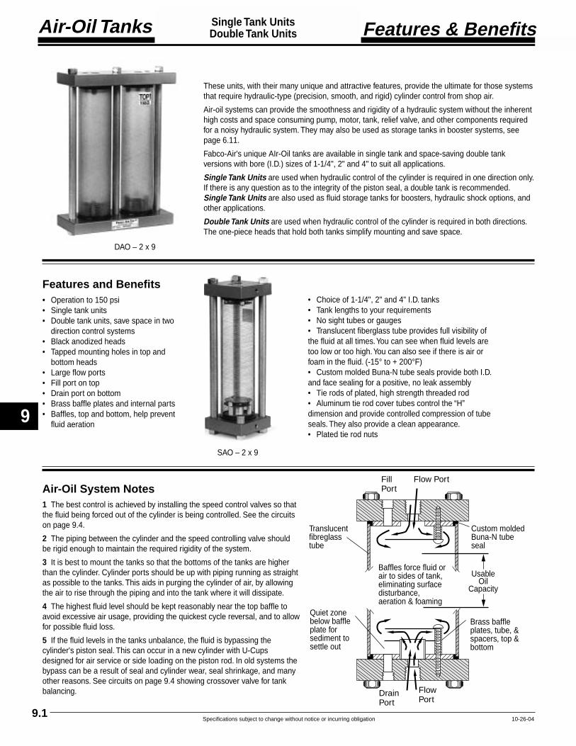
9
Air-Oil Tanks
Specifications subject to change without notice or incurring obligation
Features and Benefits• Operation to 150 psi• Single tank units• Double tank units, save space in two
direction control systems• Black anodized heads• Tapped mounting holes in top and
bottom heads• Large flow ports• Fill port on top• Drain port on bottom• Brass baffle plates and internal parts• Baffles, top and bottom, help prevent
fluid aeration
10-26-049.1
Single Tank UnitsDouble Tank Units Features & Benefits
FillPort
Flow Port
DrainPort
FlowPort
Quiet zonebelow baffleplate forsediment tosettle out
Brass baffleplates, tube, &spacers, top &bottom
Custom moldedBuna-N tubeseal
Baffles force fluid orair to sides of tank,eliminating surfacedisturbance,aeration & foaming
UsableOil
Capacity
Translucentfibreglasstube
Air-Oil System Notes1 The best control is achieved by installing the speed control valves so thatthe fluid being forced out of the cylinder is being controlled. See the circuitson page 9.4.
2 The piping between the cylinder and the speed controlling valve shouldbe rigid enough to maintain the required rigidity of the system.
3 It is best to mount the tanks so that the bottoms of the tanks are higherthan the cylinder. Cylinder ports should be up with piping running as straightas possible to the tanks. This aids in purging the cylinder of air, by allowingthe air to rise through the piping and into the tank where it will dissipate.
4 The highest fluid level should be kept reasonably near the top baffle toavoid excessive air usage, providing the quickest cycle reversal, and to allowfor possible fluid loss.
5 If the fluid levels in the tanks unbalance, the fluid is bypassing thecylinder's piston seal. This can occur in a new cylinder with U-Cupsdesigned for air service or side loading on the piston rod. In old systems thebypass can be a result of seal and cylinder wear, seal shrinkage, and manyother reasons. See circuits on page 9.4 showing crossover valve for tankbalancing.
• Choice of 1-1/4", 2" and 4" I.D. tanks• Tank lengths to your requirements• No sight tubes or gauges• Translucent fiberglass tube provides full visibility ofthe fluid at all times. You can see when fluid levels aretoo low or too high. You can also see if there is air orfoam in the fluid. (-15° to + 200°F)• Custom molded Buna-N tube seals provide both I.D.and face sealing for a positive, no leak assembly• Tie rods of plated, high strength threaded rod• Aluminum tie rod cover tubes control the “H”dimension and provide controlled compression of tubeseals. They also provide a clean appearance.• Plated tie rod nuts
DAO – 2 x 9
SAO – 2 x 9
These units, with their many unique and attractive features, provide the ultimate for those systemsthat require hydraulic-type (precision, smooth, and rigid) cylinder control from shop air.
Air-oil systems can provide the smoothness and rigidity of a hydraulic system without the inherenthigh costs and space consuming pump, motor, tank, relief valve, and other components requiredfor a noisy hydraulic system. They may also be used as storage tanks in booster systems, seepage 6.11.
Fabco-Air's unique AIr-Oil tanks are available in single tank and space-saving double tankversions with bore (I.D.) sizes of 1-1/4", 2" and 4" to suit all applications.
Single Tank Units are used when hydraulic control of the cylinder is required in one direction only.If there is any question as to the integrity of the piston seal, a double tank is recommended.Single Tank Units are also used as fluid storage tanks for boosters, hydraulic shock options, andother applications.
Double Tank Units are used when hydraulic control of the cylinder is required in both directions.The one-piece heads that hold both tanks simplify mounting and save space.

Air-Oil Tanks
9
Specifications subject to change without notice or incurring obligation4-20-049.2
Single Tank UnitsDouble Tank Units Model Number
Description SpecifyViton Seals (-15° to +200°F) -VOversize Ports
Bore Port Size Location1-1/4 1/4 NPT Top -T14
Bottom -B14Both -TB14
2 1/2 NPT Top -T12Bottom -B12Both -TB12
4 3/4 NPT Top -T34Bottom -B34Both -TB34
Any port not specified will be standard size.Extended Tie Rods
Top only -WT‡
Bottom only -WB‡
Both -WTB‡
‡ Specify Dimension “K” in inches & fractions.See page 9.3, 1/2" increments please.
Options
Model Number CodexDAO – 4 30 V–
SeriesSingle Tank SAODouble Tank DAO
Tank Height
“H” Dimension(See page 9.3)
Specify in Inches as required.
See charts at left for“Useable Oil Capacity” andsee “Tank Selection” below.
Tank Bore1-1/4"
2"4"
TankHeightInches
“H”
Tank BoreUseable Oil Capacity
Cubic Inches
Tank SelectionStep 1 Calculate work cylinder volume in cubic inches. Area x Stroke = Volume.
Step 2 Add 10% to 40% to the volume for an operating margin based on system speedand level of maintenance. The higher the speed and the lower the maintenance the higherthe operating margin should be.
Step 3 From the “Usable Oil Capacity” chart, select the Bore and Height combinationthat provides a volume equal to, or greater than, the calculated volume with operatingmargin. Base your final selection on a combination of economics, available space, portsize (system speed), and operating margin.
Example
System: 3" Bore x 6" Stroke cylinder with oil on both ends, running at low speedand well maintained.
Step 1 Volume of 3" Bore = 7.07 sq. in. Area x 6" Stroke = 42.42 cu. in. Volume
Step 2 42.42 cu. in. Volume + 10% operating margin = 46.66 cu. in. with operating margin
Step 3 Choices: DAO - 4 x 11 or DAO -2 x 23
How to Order1 Specify the Series
2 Specify the Tank Bore
3 Specify the Tank Height, “H”
4 Specify Options
Examples
DAO - 4 x 30 - V Double tank, 4" bore, “H” = 30" (263 cu. in. capacity), Viton seals
SAO - 1-1/4 x 8 Single tank, 1 1/4" bore, “H” = 8" (4 cu. in. capacity)
4 2 1-1/45 16 3 27 6 6 38 12 8 49 24 11 510 35 13 611 47 15 712 58 18 813 70 20 914 81 23 1015 92 25 1116 104 2717 115 3018 127 3319 138 3620 150 3921 161 4122 173 4423 184 4724 195 5025 207 5326 21827 22928 24029 25130 26331 27632 28833 30134 31435 32836 34037 35238 36439 376 DAO maximum40 38841 40142 41443 42744 44045 45246 46347 47748 49049 50250 51551 52752 54053 55254 56555 57856 59057 60358 61559 62860 640 SAO maximum

9
Air-Oil Tanks
Specifications subject to change without notice or incurring obligation4-20-049.3
Single Tank UnitsDouble Tank Units Standard Specifications
Q, NPTFlow PortsB__
2
C
A
C
H
KThreaded Rod Extensionfrom Head.Also see Options.Extended Tie Rods,on page 9.2
Seepage 9.2
Q, NPTFlow Ports
NutL
P, NPTDrain Port2 Places
Q, NPTFlow Port2 Places
P, NPTFill Port2 Places
Q, NPTFlow Port2 Places
MThreaded
Rod
C__2
H + C
Seepage 9.2
1/4-20 x .50 Dp.Mounting Holes4 Places
JG
EF
TOP150 PSI
MAX
Label on Front
B
Q, NPTFlow PortB__
2
C
BB__2
B
C
H
KThreaded Rod Extensionfrom Head.Also see Options.Extended Tie Rods,on page 9.2
Seepage 9.2
Q, NPTFlow Port
NutL
P, NPTDrain Port
Q, NPTFlow Port
P, NPTFill Port
Q, NPTFlow Port
MThreaded Rod
C__2
H + C
Seepage 9.2
Label on Front
1/4-20 x .50 Dp.Mounting Holes2 Places
TOP150 PSI
MAX
R
S
R S M (4 Places)
T U
M (3 Places)
B__2
U
T
U
T 9.94
M (5 Places)
A__2
B__2
Single Tank Unit, SAO
Tie Rod PatternDAO –1-1/4 & DAO –2
Tie Rod PatternDAO –4
Tie Rod PatternSAO –1-1/4, SAO –2, SAO –4
Double Tank Unit, DAO
Bore 1-1/4 2 4Vol./In. 1.22 3.14 12.56
A 4.75 7.50 10.75B 2.00 3.00 5.25C 0.50 0.75 1.00E 0.38 0.50 1.88F 4.38 7.00 8.88G 1.31 2.13 2.63H See page 9.2J 3.44 5.38 8.13K 0.27 0.38 0.50L 0.22 0.33 0.43M 1/4-20 3/8-16 1/2-13P 1/8 1/8 1/4Q 1/8 1/4 1/2R 0.25 0.38 0.69S 1.50 2.25 3.88T 0.25 0.50 0.69U 2.13 3.25 3.88

Air-Oil Tanks
9
Specifications subject to change without notice or incurring obligation4-12-04 9.4
Single Tank UnitsDouble Tank Units Typical Circuits
Cylinder
SingleTankUnit
Air Supply
FlowControl
Muffler
Directional ControlValve 4-Way – Air
Cylinder
DoubleAir - OilTanks
Air Supply
Directional ControlValve 4-Way – Air
FlowControl
Muffler
Crossoverand shut offprovide easybalancing oftank levels
SingleAir - Oil
Tank
Air Supply
Muffler
Cylinder
Directional ControlValve 4-Way – Air
RV-1Sequence ValveSee page 13.4for details
Shut Off2-Way - Oil
Needle Valve
Cylinder
DoubleAir - OilTanks
Air Supply
Directional ControlValve 4-Way – Air
Muffler
Crossover and shut off provide easy balancing of tank levels
Stop and Hold
Free to Move
① Shut Off 2-Way - Oil
➁ Shut Off2-Way - Oil
NeedleValve
ControlledRate
RapidRate
One SpeedSingle Air-Oil Tank and flow control givehydraulic control, one speed, one directionwith rapid reverse.
Can be used for Multi-Power® Cylinder andMulti-Power® Air Press with Option -HS.See page 5.4 and catalog #FP-16.
Two Speed Stop & HoldDouble Air-Oil Tanks with shut-off valves & needle valve provide:
1 Stop and hold in either direction at any point in cylinder travel.
2 Choice of rapid or control rate in either direction at any point ofcylinder travel.
Two SpeedDouble Air-Oil Tanks and flow controls givehydraulic control, one speed, each direction.
Two Speed & Shock ControlSingle Air-Oil Tank with sequence, needle and shut-off valves give:
1. Rapid extend stroke.2. Automatic switch to controlled rate when resistance is met
and pressure builds up.3. Fluid catches cylinder when built-up forces are suddenly
released (such as in a punching operation), thus controllingthe shock that could otherwise occur.
4. Automatic return to rapid rate on return stroke.
Can be used for Multi-Power®
Cylinder and Multi-Power® AirPress with Option -HS. Seepage 5.4 and catalog # FP16.

Directional Control Valves
11
Specifications subject to change without notice or incurring obligation11.1
11-8-04
Port Flow Rate/ Function Series Actuators Page NumberSize Factor
10-32 Cv = 0.05 2 Way Modular Solenoid 11.3 - 11.4& to 3 Way Manifold
1/8 NPT Cv = 0.23 4 Way, 2 PositionModular
1/8 NPT Cv = 0.05 2 Way Hex Solenoid 11.5–11.6& to 3 Way Body
1/4 NPT Cv = 0.23
1/8 NPT Cv = 0.27 2 Way 18 Manual 11.7-11.83 Way Mechanical 11.7-11.8
4 Way, 2 Position Pilot 11.7-11.8Solenoid 11.9-11.12
1/4 NPT Cv = 1.0 3 Way 14 Manual 11.13-11.164 Way, 2 Position Mechanical 11.13-11.144 Way, 3 Position Pilot 11.13-11.15
Solenoid 11.17-11.22
1/4 NPT Cv = 1.0 3 Way M14 Manual 11.13Stacking 4 Way, 2 Position Mechanical 11.13
Pilot 11.13Solenoid 11.20
3/8 NPT Cv = 1.0 3 Way 34 Manual 11.13-11.164 Way, 2 Position Mechanical 11.13-11.144 Way, 3 Position Pilot 11.13-11.15
Solenoid 11.17-11.22
3/8 NPT Cv = 2.2 3 Way 12A Manual 11.23-11.28& to 4 Way, 2 Position Pilot
1/2 NPT Cv = 3.9 4 Way, 3 Position SolenoidManifold
3/8 NPT Cv = 2.4 3 Way 38 Manual 11.23–11.28to 4 Way, 2 Position Pilot
Cv = 4.1 4 Way, 3 Position Solenoid
1/2 NPT Cv = 2.4 3 Way 12 Manual 11.23–11.28to 4 Way, 2 Position Pilot
Cv = 4.1 4 Way, 3 Position Solenoid
1/2 NPT Cv = 6.2 3 Way 12B Manual 11.23–11.28High Flow 4 Way, 2 Position Pilot
Solenoid
Section 11 Index

Specifications subject to change without notice or incurring obligation
11
Directional Control Valves
11
11.2
Section 11 Index
Series Quick Page No.
Modular Manifold . . . . . . . . . . . . . . . 11.3
Hex Body . . . . . . . . . . . . . . . . . . . . . 11.5
18 . . . . . . . . . . . . . . . . . . . . . . . . . . 11.7
14 . . . . . . . . . . . . . . . . . . . . . . . . . . 11.13
M14 . . . . . . . . . . . . . . . . . . . . . . . . . 11.13
34 . . . . . . . . . . . . . . . . . . . . . . . . . . 11.13
12A . . . . . . . . . . . . . . . . . . . . . . . . . 11.23
38 . . . . . . . . . . . . . . . . . . . . . . . . . . 11.23
12 . . . . . . . . . . . . . . . . . . . . . . . . . . 11.23
12B . . . . . . . . . . . . . . . . . . . . . . . . . 11.23
11-8-04

Directional Control Valves
11
Specifications subject to change without notice or incurring obligation
Modular Manifold10-32 & 1/8 NPT2, 3 & 4 Way
12-22-06
Miniature 53 STYLE Solenoid Valves2, 3 or 4 Way - Modular Manifolding
2, 3 or 4 Way - Single Mounting
Time Proven • Space Saving • Reliable• 2, 3 and 4 Way SolenoidValves with 10-32 or 1/8 NPT ports are available in singular or modularmanifold versions. Any combination of function and ports can be combined inthe same manifold stack to save time, space and plumbing. With pressuremanifold plugging, two or more pressure ranges and/or medias can becontrolled in the same stack.
• Quantity of assembled Banks• Valve models (start left to right, see photo above)• Mounting brackets, if desired #101Example… Using the photo above1 Bank consisting of:
1 113-M-C-1 120/601 103-M-F-1 120/601 104-M-G-1 120/601 114-M-C-1 120/601 Pair #101 Mounting Brackets
For Complete Assembled Banks Specify:
Operating PressuresApplies to all 4 Way 104 and 114 series valves.See Orifice Information below for pressure rangesof 2 & 3 Way valves.
STANDARD SPRING40 psi Minimium150 psi Maximum with #1, 3/64 orifice.See Orifice Information below for Maximum with other orifices.
OPTIONAL LOW PRESSURE SPRING20 psi:
20 psi Minimum25 psi Maximum
25 psi:25 psi Minimum60 psi Maximum
Inlet Cylinder BasicFunction Port Port Model No.
Valves for 2 Way N.C. 1/8 NPT 1/8 NPT 112-SIndividual 3 Way N.C. 1/8 NPT 1/8 NPT 113-SMounting & 4 Way 10-32 10-32 104-S-10Individual 4 Way 1/8 NPT 10-32 104-S-18Inlet 4 Way 1/8 NPT 1/8 NPT 114-S
Valves for 2 Way N.C. 10-32 10-32 102-SMModular 3 Way N.C. 10-32 10-32 103-SMMounting &Individual Inlet
Valves for 2 Way N.C. 1/8 NPT 10-32 102-MModular 2 Way N.C. 1/8 NPT 1/8 NPT 112-MMounting & 3 Way N.C. 1/8 NPT 10-32 103-MManifolded 3 Way N.C. 1/8 NPT 1/8 NPT 113-MInlet (Pressure 4 Way 1/8 NPT 10-32 104-MManifolded) 4 Way 1/8 NPT 1/8 NPT 114-M
All Mountings 3 Way Normally Open use 4 Way & Plug N.C. port
OPTION INFORMATION
ORIFICE INFORMATION
• Viton Seals for media compatibility specify Option -V• Coils & Housing, See page 11.29.• Low Pressure Spring - 4 Way Only - See Operating Pressures.• Pro-Coat™ (Electroless Nickel Plate) Option -N, See page 1.10.• Special Bank Assembly (Plugs, Fittings, Wire Terminals) See Pg iii.• Normally Open (N.O.) 2 & 3 Way Valves - Use 4 Way Valve & Plug N.C. Port.
Accessories• Mounting Brackets Part # 101.• Connectors for Mini-DIN “F”, See page 11.30.• SM-10 Muffler, See page 14.1.
CFM – Flow @
Cv Factor 2 Way N.C. 3 Way N.C. 4 Way 100 psi 50 psiNumber 0 1/32 .022 500 psi 200 psi 150 psi 1.3 0.9Number 1 3/64 .055 400 150 150 3.5 2.0Number 2 1/16 .075 200 100 100 5.8 3.4Number 3 3/32 .156 100 60 80 9.0 6.0Number 4 1/8 .230 75 30 Not Available Not Available 8.0
Available Orifices and Equivalent Maximum PressureRatings for AC Voltages (DC Ratings Slightly Lower)
For Each Valve Specify:EXAMPLE
Basic Model Number 103-M See Chart BelowLetter for Housing -C C Conduit, G Grommet, F DINNumber for Seat -1 See orifice information chart belowOptions See option Information belowVolts & Hertz 120/60 See solenoid information Page11.29
Example: 3 Way modular mounting with manifold inlet, 1/8 NPT inlet,10-32 Cylinder Port, Conduit Housing, 3/64 Seat, 120 Volts/60 HZ.Model Number = 103-M-C-1, 120/60
11.3

Specifications subject to change without notice or incurring obligation
11
Directional Control Valves
11
Modular Manifold10-32 & 1/8 NPT2, 3 & 4 Way
8-26-04
See Housing Detailson Page 11.29
1.13Typ.
.38Typ.
[ (Quantity of Valves) x 1.13] + .75
.56Typ.
1.38 Typ.
.83 Typ.
.19 Typ..19 Typ.
10-32 EXH Port
SM-10 Muffler,See page 14.4.
.25
.03.68
#101 Mounting Bracket (Pair)
2.80
.55 Typ.
1.02
.20 Dia. 4 Places
.55.83
Dual Cylinder Ports10-32 NC CYL Ports
102-M
.55.83
Dual Cylinder Ports10-32 NC CYL Ports
103-M
.21.21
.55.83
10-32 NC CYL Port
104-M
.17.24
10-32 NO CYL Port
.17
1.2110-32 EXH PortDo Not Restrict
Spring Cap
.55.83
1/8 NPT CYL Port
112-M
.55 Ref.
.55.83
1/8 NPT CYL Port
113-M
.10
.791.19
1/8 NPT NO CYL Port
114-M
.25
SpringCap
1/8 NPT NC CYL Port
.17
1.02
.36
10-32 EXH PortDo Not Restrict
1.38
.22
.83
1.13.78.17
2.68
1.13.78
.20 Dia. 2 Places.Note: Mounting screwheads may restrict housing rotation.
See Housing Details on Page 11.29
SpringCap
10-32 NC CYL Port
10-32 EXH Port
.71.55.38
.83.38.56
10-32 NO CYL Port
10-32 EXH PortDo Not Restrict
INLET PORT104-S-10 10-32
104-S-18 1/8 NPT
1.81
.22
1.02
1.13.78.17
2.68
1.13.91
.20 Dia. 2 Places.Note: Mounting screwheads may restrict housing rotation.
See Housing Details on Page 11.29
SpringCap
1/8 NPT NC CYL Port
10-32 EXH Port
.80.55.38
1.02.17.56
1/8 NPT NO CYL Port10-32 EXH PortDo Not Restrict
1.38
.22
.83
1.13.78.17
2.67
1.13.55
.20 Dia. 2 Places. Note: Mounting screwheads may restrict housing rotation.
See Housing Details on Page 11.29
10-32 EXH Port
.83.56
1/8 NPT112-S Cyl113-S IN
1/8 NPT112-S IN113-S Cyl
See Housing Detailson Page 11.29
102-SM 103-SM
1.13Typ.
.38Typ.
[ (Quantity of Valves) x 1.13] + .75
.56Typ.
1.38 Typ.
.83 Typ.
.19 Typ..19 Typ.10-32 10-32
10-32 IN Port (102-SM)10-32 CYL Port (103-SM)
10-32 CYL Port 10-32 IN Port
10-32 EXH Port (103-SM)
2.80
.03 .89.68
#101 Mounting Bracket (Pair).20 Dia.4 Places
MODEL 114-S
MODELS 102-M, 103-M, 104-M, 112-M, 113-M & 114-MSupply pressure can be connected to either or both ends of the stack. Due to
the fact that the supply pressure port on all “M” valve bodies is tapped on bothsides, the pressure manifold can be plugged at any point within the stack. Thisallows you to supply the stack with two different pressures or media, one fromeach end.
For more than two inputs a port block can be provided in midstack. Spacerscan be included for applications requiring the larger EXPLOSION PROOFoperator. Contact Fabco-Air with your specific requirements.
MODEL 102-SM (2-Way), 103-SM (3-Way)
MODEL 104-S-10 (10-32 Inlet Port)MODEL 104-S-8 (1/8 NPT Inlet Port)
MODEL 112-S (2-Way), 113-S (3-Way)
11.4

Directional Control Valves
11
Specifications subject to change without notice or incurring obligation
IN OUT Basic Model
1/8 10-32 X-82-★ -✦ -NO11/8 1/8 X-82-★ -✦ -NO21/4 10-32 X-42-★ -✦ -NO11/4 1/8 X-42-★ -✦ -NO2
IN OUT Basic Model
1/8 1/8 X-882-★ -✦1/8 1/4 X-482-★ -✦1/4 1/8 X-842-★ -✦1/4 1/4 X-442-★ -✦
Hex Body1/8 & 1/4 NPT2 & 3 Way Valves
11-8-04
In
Out
In
Out
De-Energized Energized
In
Out
In
Out
De-Energized Energized
In
Out
In
OutDe-Energized Energized
In
Out
In
Out
De-Energized Energized
In
Out
In
OutDe-Energized Energized
In Out In Out
De-Energized Energized
In
Out
In
Out
De-Energized Energized
In
Out
In
Out
De-Energized Energized
In
Out
In
Out
De-Energized Energized
In
Out
In
Out
De-Energized Energized
Hex Body 53 STYLE Solenoid Valves
IN OUT Basic Model
10-32 1/8 82-★ -✦ -NO11/8 1/8 82-★ -✦ -NO2
10-32 1/4 42-★ -✦ -NO11/8 1/4 42-★ -✦ -NO2
2 WAY NORMALLY OPENBODY STYLE 1 SIDE PORT
2 WAY NORMALLY CLOSEDBODY STYLE 1 SIDE PORTS
BODY STYLE 2 FEMALE BOTTOM PORT BODY STYLE 2 FEMALE BOTTOM PORT
BODY STYLE 2 FEMALE BOTTOM PORT BODY STYLE 2 FEMALE BOTTOM PORT
BODY STYLE 3 MALE BOTTOM PORT BODY STYLE 3 MALE BOTTOM PORT
BODY STYLE 3 MALE BOTTOM PORT BODY STYLE 3 MALE BOTTOM PORT
IN OUT Basic Model
1/8 1/8 82-★ -✦1/4 1/4 42-★ -✦
IN OUT Basic Model
10-32 1/8 F-82-★ -✦ -NO11/8 1/8 F-82-★ -✦ -NO2
10-32 1/4 F-42-★ -✦ -NO11/8 1/4 F-42-★ -✦ -NO2
IN OUT Basic Model
1/8 1/8 F-882-★ -✦1/8 1/4 F-842-★ -✦1/4 1/8 F-482-★ -✦1/4 1/4 F-442-★ -✦
IN OUT Basic Model
1/8 10-32 FX-82-★ -✦ -NO11/8 1/8 FX-82-★ -✦ -NO21/4 10-32 FX-42-★ -✦ -NO11/4 1/8 FX-42-★ -✦ -NO2
IN OUT Basic Model
1/8 1/8 FX-882-★ -✦1/8 1/4 FX-482-★ -✦1/4 1/8 FX-842-★ -✦1/4 1/4 FX-442-★ -✦
IN OUT Basic Model
10-32 1/8 082-★ -✦ -NO11/8 1/8 082-★ -✦ -NO2
10-32 1/4 042-★ -✦ -NO11/8 1/4 042-★ -✦ -NO2
IN OUT Basic Model
1/8 1/8 882-★ -✦1/8 1/4 842-★ -✦1/4 1/8 482-★ -✦1/4 1/4 442-★ -✦
OPTIONS: Specify Suffix• 1/8 NPT Adapter (3 Way N.C. Top Exhaust) ............... -A ....... See Pg. 11.6• Viton Seals (for media compatibility) ........... -V• Explosion Proof ............................... -EP ...... See Pg. 11.30• Pro-Coat™ (Electroless Nickel Plate) ......... -N ....... See Pg. 1.10• Spade Electrical Connections See Pgs. 11.29 &
11.30ACCESSORIES:
• Solenoid Exhaust Muffler .............. SM-10 .... See Page 14.4• Connectors for Mini-DIN “F” .......................... See Pg. 11.30
• Body Hex aluminum, black anodized - 3 Different porting styles.• Media Air, water & other fluids compatible with standard Buna-N
seals and aluminum.• Power See page 11.29
• Operating Temperature:0°F (–18°C) to +104°F (40°C) ambient.0°F (–18°C) to +150°F (65°C) media.
• Voltages See page 11.29• Operating Pressure See chart with orifice information• Internal Parts Stainless Steel
HOW TO ORDER
Insert Letter for Housing at ★
See Chart, Orifice Information
EXAMPLEBasic Model Number X883 See Model Charts
-C C Conduit, G Grommet, F DINSee Solenoid Information Page 11.29
Number for Orifice at ✦ -1All 3 Way EX Orifices are 1/16Options See Chart, Option InformationVolts & Hertz 120/60 See Solenoid Information Page 11.29
Example: 3 Way N.C., 1/8 NPT Male Bottom Inlet, 1/8 NPT SideCylinder, Conduit Housing, 3/64 Seat, 120 Volts/60 HZ.Model Number = X883-C-1, 120/60
11.5

Specifications subject to change without notice or incurring obligation
11
Directional Control Valves
11IN CYL EX† Basic Model
1/8 1/8 10-32 X-883-★ -✦1/8 1/4 10-32 X-483-★ -✦1/4 1/8 10-32 X-843-★ -✦1/4 1/4 10-32 X-443-★ -✦
† For optional 1/8 NPT Adapter add Suffix “A”
IN CYL EX† Basic Model
1/8 1/8 10-32 883-★ -✦1/8 1/4 10-32 843-★ -✦1/4 1/8 10-32 483-★ -✦1/4 1/4 10-32 443-★ -✦
† For optional 1/8 NPT Adapter add Suffix “A”
IN CYL EX† Basic Model
1/8 1/8 10-32 FX-883-★ -✦1/8 1/4 10-32 FX-483-★ -✦1/4 1/8 10-32 FX-843-★ -✦1/4 1/4 10-32 FX-443-★ -✦
† For optional 1/8 NPT Adapter add Suffix “A”
IN CYL EX Basic Model
10-32 1/8 1/8 883-★ -✦ -NO11/8 1/8 1/8 883-★ -✦ -NO2
10-32 1/8 1/4 483-★ -✦ -NO11/8 1/8 1/4 483-★ -✦ -NO2
10-32 1/4 1/8 843-★ -✦ -NO11/8 1/4 1/8 843-★ -✦ -NO2
10-32 1/4 1/4 443-★ -✦ -NO11/8 1/4 1/4 443-★ -✦ -NO2
Hex Body1/8 & 1/4 NPT2 & 3 Way Valves
8-26-04
3.241/8
NPTPort
2.6810-32Port
1.13.39
.73
1.00 Hex
No. 10-32 x 1/4Deep Mt'g Thds.
3.671/8
NPTPort
3.1110-32Port
1.56
.83
1.00 Hex
3.171/8
NPTPort
2.6110-32Port
1.06.33
1.00 Hex
.50
See Pg. 11.29 for Housing Details See Pg. 11.29 for Housing Details See Pg. 11.29 for Housing Details
In
Cyl
In
Cyl
De-Energized Energized
Ex Ex
In
Cyl
In
Cyl
De-Energized Energized
Ex Ex
In
Cyl
In
Cyl
De-Energized Energized
Ex Ex
In Cyl In Cyl
ExDe-Energized Energized
Ex
In
Cyl
In
Cyl
De-Energized EnergizedEx Ex
In
Cyl Cyl
In
De-Energized EnergizedEx Ex
In
Cyl
In
Cyl
De-Energized EnergizedEx Ex
In
Cyl
In
Cyl
De-Energized EnergizedEx Ex
ORIFICE INFORMATIONAvailable Orifices and Equivalent Maximum Pressure Ratings for AC Voltages (DC Ratings Slightly Lower) CFM – Flow @
Cv Factor 2 Way N.O. 2 Way N.C. 3 Way N.O. 3 Way N.C. 100 psi 50 psiNumber 0 1/32 .022 150 psi 500 psi 150 psi 200 psi 1.3 0.9Number 1 3/64 .055 125 400 125 150 3.5 2.0Number 2 1/16 .075 100 200 100 100 5.8 3.4Number 3 3/32 .156 NA 100 NA 60 9.0 6.0Number 4 1/8 .230 NA 75 NA 30 NA 8.0All 3 way (EX) exhaust orifices are 1/16. All 3 way (EX) exhaust orifices are 1/16.
3 WAY NORMALLY OPENBODY STYLE 1 SIDE PORT
3 WAY NORMALLY CLOSEDBODY STYLE 1 SIDE PORTS
IN CYL EX† Basic Model
10-32 1/8 1/8 83-★ -✦ -NO11/8 1/8 1/8 83-★ -✦ -NO2
10-32 1/4 1/4 43-★ -✦ -NO11/8 1/4 1/4 43-★ -✦ -NO2
BODY STYLE 2 FEMALE BOTTOM PORT BODY STYLE 2 FEMALE BOTTOM PORT
IN CYL EX Basic Model
10-32 1/8 1/8 F-883-★ -✦ -NO11/8 1/8 1/8 F-883-★ -✦ -NO2
10-32 1/8 1/4 F-483-★ -✦ -NO11/8 1/8 1/4 F-483-★ -✦ -NO2
10-32 1/4 1/8 F-843-★ -✦ -NO11/8 1/4 1/8 F-843-★ -✦ -NO2
10-32 1/4 1/4 F-443-★ -✦ -NO11/8 1/4 1/4 F-443-★ -✦ -NO2
IN CYL EX† Basic Model
1/8 1/8 10-32 F-883-★ -✦1/8 1/4 10-32 F-443-★ -✦1/4 1/8 10-32 F-843-★ -✦1/4 1/4 10-32 F-443-★ -✦
BODY STYLE 2 FEMALE BOTTOM PORT
BODY STYLE 3 MALE BOTTOM PORT
BODY STYLE 3 MALE BOTTOM PORT
BODY STYLE 3 MALE BOTTOM PORT
IN CYL EX† Basic Model
1/8 1/8 10-32 83-★ -✦1/4 1/4 10-32 43-★ -✦
† For optional 1/8 NPT Adapter add Suffix “A”
† For optional 1/8 NPT Adapter add Suffix “A”
BODY STYLE 1 – Side Ports BODY STYLE 2 – Female Bottom Port BODY STYLE 3 – Male Bottom Port
11.6

Directional Control Valves
11
Specifications subject to change without notice or incurring obligation
18 Series1/8 NPT2, 3 & 4 Way
8-26-04
1/8 NPT Standard.10-32 = Option -E
Pilot Bushing
Standard or Light SpringHousing 9/16 Hex
9/16 Hex
.13
.38
1.25Dia.
1.63
1/8 NPT Standard.10-32 = Option -E
.25 Dia..78
.50
.25 Stroke
.75 Dia.
.13
.1.88
.25 Stroke
.13.88
Standard 2 Way & 3 Way springreturn are normally closed. Fornormally open the actuators may beexchanged end for end or byspecifying -20 for -2 & -30 for -3.Minimum pilot pressure:
Standard spring . . . . . . . . 60 psiLight spring (Option -L) . . 40 psiDouble pilot . . . . . . . . . . . 20 psi
2 Way 3 Way 4 WaySingle Pilot - Spring Return18SP-2 18SP-3 18SP-4Double pilot18DP-2 18DP-3 18DP-4Replacement spool & seals1800-902 1800-903 1800-904
Light spring, Option -L10-32 pilot port, Option -E
Air Pilot
Air Pilot Amplifier
Roller Cam
Rod Actuator
1" Delrin piston in aluminum housingmeets low pressure requirements.Standard 2 Way & 3 Way springreturn are normally closed. Fornormally open the actuators maybe exchanged end for end or byspecifying -20 for -2 & -30 for -3.Minimum pilot pressure:
Standard spring . . . . . . . . 10 psiLight spring (Option -L) . . . 7 psiAgainst 0 psi pilot . . . . . . . 2 psi
2 Way 3 Way 4 WaySingle Pilot (Amplifier) - Spring Return18SA-2 18SA-3 18SA-4Double pilot - 2 amplifiers18DA-2 18DA-3 18DA-4Double pilot - 1 amplifier, 1 air pilot18DAP-2 18DAP-3 18DAP-4
When both pilots are pressurized,the amplifier overrides.
Replacement spool & seals1800-902 1800-903 1800-904
Light spring, Option -L10-32 pilot port, Option -E
Plated steel rod in brass bushing.Standard 2 Way & 3 Way springreturn are normally closed. Fornormally open the actuators may beexchanged end for end or specify bysubstituting -20 for -2 & -30 for -3.Force to actuate:
Standard spring . . . . . . . . 6.5 lb.Light spring (Option -L) . . 5.0 lb.Double Rod . . . . . . . . . . . 1.2 lb.
2 Way 3 Way 4 WaySingle Rod - Spring Return18SR-2 18SR-3 18SR-4Single Rod- Pilot Return18SRP-2 18SRP-3 18SRP-4Double rod18DR-2 18DR-3 18DR-4Replacement spool & seals1800-902 1800-903 1800-904
Light return spring, Option -L
Case hardened steel roller and shaftin hard anodized aluminum housing.Standard 2 Way & 3 Way spring returnare normally closed. For normallyopen specify by substituting -20 for -2& -30 for -3.Force to actuate:
Standard spring . . . . . . . . 6.5 lb.Light spring (Option -L) . . 5.0 lb.Double Cam . . . . . . . . . . 1.2 lb.
2 Way 3 Way 4 WaySingle Cam - Spring Return18CR-2 18CR-3 18CR-4Single Cam - Pilot Return18CRP-2 18CRP-3 18CRP-4Replacement spool & seals for above1800-912 1800-913 1800-914Double cam18CCR-2 18CCR-3 18CCR-4Replacement spool & seals1800-922 1800-923 1800-924
Light return spring, Option -L
1
212 10
12 10
21.13
1.31
.16
.811.44
1.81
.20 Dia. Clearancefor #10 Bolt
.381.00
1.25
Primary Secondary
2 WAY31
2
12 10
3 Way
This 3 Way Valve maybe used for any 3 Way,Selector or Diverterservice.
12 10
21.13
1.44
.16
.811.58
2.02
.20 Dia. Clearancefor #10 Bolt
.381.00
1.25
Primary Secondary
3
1.34.63
3 1
214 12
5
4
4 Way - 5 Port ‡
14 12
2
1.52
1.44
.16
1.201.97
2.41
.20 Dia. Clearancefor #10 Bolt
.38
1.25
Primary Secondary
3
1.73.63
5
4
.89.67
1.00
1/8 NPT PORTED, MANUAL, MECHANICAL AND PILOT OPERATED AIR VALVES – “The Finest in Simplicity”2, 3 and 4 Way - 2 Position – Operation to 150 psi AirSuitable for Vacuum directional flow applications, but NOT for holding vacuum.Short stroke of lightweight Delrin® spools provides fast, positive, and reliable response.
Valve Body Dimensions
Note 1: Specify Normally Open bysubstituting -20 for -2 & -30 for -3.
Standard 2 & 3 way spring return models are normally closed. Models with threadin actuators may be converted to normally open by exchanging actuators end forend. Other models require specification and factory assembly. See note 1.
‡ 4 way - 5 port May be used as either singleinlet - dual exhaust or dual inlet - single exhaust.
11.7

Specifications subject to change without notice or incurring obligation
11
Directional Control Valves
11
• Prelubed with Magnalube®–G Grease• Interchangeability of Parts• Cv = 0.27
14.2 SCFM Free Flow toAtmosphere at 80 psi Supply
• Operating temperature 0° to +180°F;Solenoid controlled models +150°F max.See pages 11.9 and 11.11.
18 Series1/8 NPT2, 3 & 4 Way
11-8-04
.75Dia. .97
.50
.25 Stroke
1.25Dia. .91
.50
.25 Stroke
1.38Dia.
.811.65
.50
3/4-16.25 Stroke
(2) 7/8 Hex x .13 thick brass nuts included
1.00
16°
1.50
Leverposition when spring returned
3.38
.75 Dia.
Palm ButtonAssembly
No. 1800-1 Large ButtonNo. 1800-2 Small Button
Panel Mount Button AssemblyFor Detented (with Spool)No. 1800-7-2 (2W NC) 1800-7-20 (2W NO)
1800-7-3 (3W NC) 1800-7-30 (3W NO)Above NOT interchangeable End for End1800-7-4 (4 Way)
For Spring or Pilot Return (No Spool)1800-8 (2 or 3 Way, NO or NC, and 4 Way))
Rod ActuatorAssembly
No. 1800-3
Spring HousingAssembly
No. 1800-4 Light Spring only (for Option L).No. 1800-5 Standard Spring onlyNo. 1800-46 Light Spring & Housing Ass'y (for Option -L).No. 1800-56 Standard Spring & Housing Assembly.
MOST THREADED-IN OPERATORS ARE INTERCHANGEABLE BETWEEN ENDSPilot Bushing
No. 1800-10 10-32 PortNo. 1800-18 1/8 NPT Port
Un-anodized aluminum button withplated steel rod in brass bushing.Standard 2 Way & 3 Way springreturn are normally closed. Fornormally open the actuators may beexchanged end for end or specify bysubstituting -20 for -2 & -30 for -3.Force to actuate:
Standard spring . . . . . . . . 6.5 lb.Light spring (Option -L) . . 5.0 lb.Double Button . . . . . . . . . 1.2 lb.
2 Way 3 Way 4 WaySingle Button - Spring Return18PS-2 18PS-3 18PS-4Single Button - Pilot Return18PSP-2 18PSP-3 18PSP-4Double Button18PPS-2 18PPS-3 18PPS-4Replacement spool & seals1800-902 1800-903 1800-904
Light spring Option -L
Small Palm Button
Large Palm Button
Hand Lever
Panel Mount Button
Red anodized aluminum button withplated steel rod in brass bushing.Standard 2 Way & 3 Way springreturn are normally closed. Fornormally open the actuators may beexchanged end for end or specify bysubstituting -20 for -2 & -30 for -3.Force to actuate:
Standard spring . . . . . . . . 6.5 lb.Light spring (Option -L) . . 5.0 lb.Double Button . . . . . . . . . 1.2 lb.
Phenolic button with plated steel rodin brass bushing; black buttonstandard, red button Option -R.Standard 2 Way and 3 Way assem-blies are normally closed with knob inthe “out” position. For normally openspecify by substituting -20 for -2 and -30 for -3.Force to actuate:
Standard spring . . . . . . . . 6.5 lb.Light spring (Option -L) . . 5.0 lb.Double Button . . . . . . . . . 1.2 lb.Detented . . . . . . . . . . . . . 3.0 lb.
Air Pilot Amplifier1/8 NPT Standard
No. 18 AMP-1 1/8 NPT PortNo. 10 AMP-1 10-32 Port Option -E
Fabco-Air has the expertiseand willingness to design.modify and adapt these valvesto your necessary and specificjob requirements. Pleaseadvise us of your needs.
Hardened & plated steel shaft withunique connection to spool results inpositive shifting. Standard 2 Way & 3Way spring return are normallyclosed. For normally open specify bysubstituting -20 for -2 & -30 for -3.Force to actuate:
Standard spring . . . . . . . . 4.0 lb.Light spring (Option -L) . . 3.0 lb.Detented . . . . . . . . . . . . . 2.0 lb.
• Aluminum bar body• Anodized black• Honed & burnished bore• Pressure balanced spool• Delrin spool• Buna-N seals• Operation to 150 psi• 4 Way - 5 port may be used as either
single inlet - dual exhaust or dual inlet - single exhaust.
2 Way 3 Way 4 WaySingle Button - Spring Return18PL-2 18PL-3 18PL-4Single Button - Pilot Return18PLP-2 18PLP-3 18PLP-4Double Button18PPL-2 18PPL-3 18PPL-4Replacement spool & seals1800-902 1800-903 1800-904
Light spring Option -L
2 Way 3 Way 4 WaySpring Return18PMS-2 18PMS-3 18PMS-4Pilot Return18PMP-2 18PMP-3 18PMP-4Replacement spool & seals for above.1800-902 1800-903 1800-904Detented (Push Pull)18PMD-2 18PMD-3 18PMD-4Replacement spool & seals1800-942† 1800-943† 1800-944†Light spring Option -L
2 Way 3 Way 4 WaySpring Return18HLS-2 18HLS-3 18HLS-4Detented18HL-2 18HL-3 18HL-4Replacement spool & seals1800-932† 1800-933† 1800-934†† Includes factory assembled spool attachments.Light spring Option -L
FEATURES OPTIONS• Light spring – Specify Option -L• Viton seals – Specify Option -V• Spools for bleeder pilot• Multiple stacking with or without
common inlet. Consult factory.Note 1: Specify Normally Open bysubstituting -20 for -2 & -30 for -3.
11.8
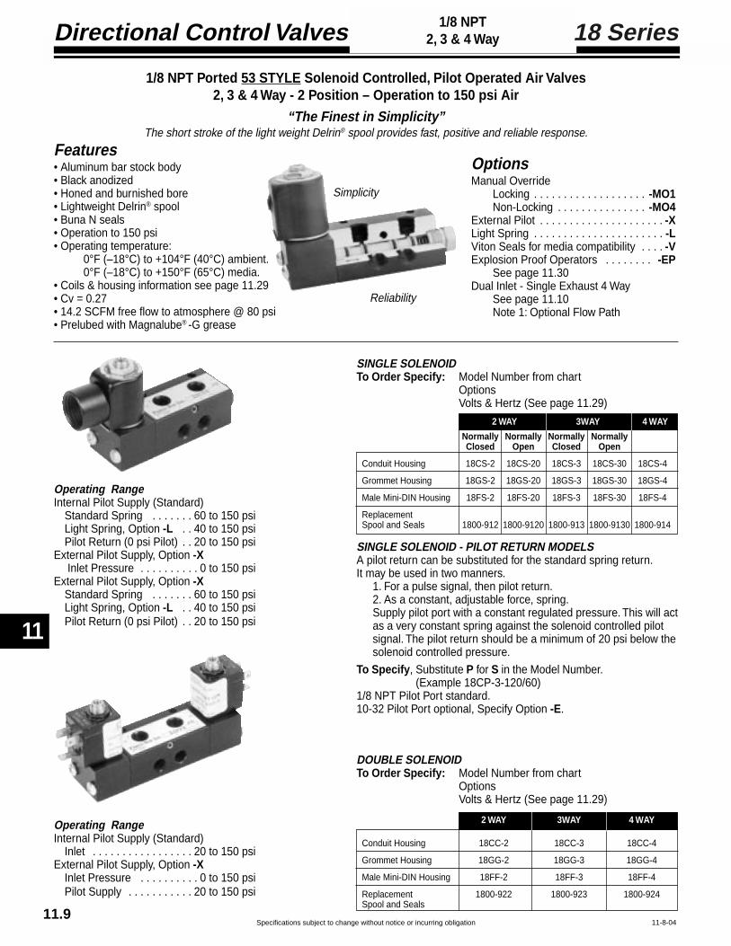
Directional Control Valves
11
Specifications subject to change without notice or incurring obligation
18 Series1/8 NPT2, 3 & 4 Way
11-8-04
1/8 NPT Ported 53 STYLE Solenoid Controlled, Pilot Operated Air Valves2, 3 & 4 Way - 2 Position – Operation to 150 psi Air
“The Finest in Simplicity”The short stroke of the light weight Delrin® spool provides fast, positive and reliable response.
Features• Aluminum bar stock body• Black anodized• Honed and burnished bore• Lightweight Delrin® spool• Buna N seals• Operation to 150 psi• Operating temperature:
0°F (–18°C) to +104°F (40°C) ambient.0°F (–18°C) to +150°F (65°C) media.
• Coils & housing information see page 11.29• Cv = 0.27• 14.2 SCFM free flow to atmosphere @ 80 psi• Prelubed with Magnalube® -G grease
OptionsManual Override
Locking . . . . . . . . . . . . . . . . . . . -MO1Non-Locking . . . . . . . . . . . . . . . -MO4
External Pilot . . . . . . . . . . . . . . . . . . . . . -XLight Spring . . . . . . . . . . . . . . . . . . . . . . -LViton Seals for media compatibility . . . . -VExplosion Proof Operators . . . . . . . . -EP
See page 11.30Dual Inlet - Single Exhaust 4 Way
See page 11.10Note 1: Optional Flow Path
Operating RangeInternal Pilot Supply (Standard)
Standard Spring . . . . . . . 60 to 150 psiLight Spring, Option -L . . 40 to 150 psiPilot Return (0 psi Pilot) . . 20 to 150 psi
External Pilot Supply, Option -X Inlet Pressure . . . . . . . . . . 0 to 150 psi
External Pilot Supply, Option -XStandard Spring . . . . . . . 60 to 150 psiLight Spring, Option -L . . 40 to 150 psiPilot Return (0 psi Pilot) . . 20 to 150 psi
Operating RangeInternal Pilot Supply (Standard)
Inlet . . . . . . . . . . . . . . . . . 20 to 150 psiExternal Pilot Supply, Option -X
Inlet Pressure . . . . . . . . . . 0 to 150 psiPilot Supply . . . . . . . . . . . 20 to 150 psi
2 WAY 3WAY 4 WAY
Normally Normally Normally NormallyClosed Open Closed Open
Conduit Housing 18CS-2 18CS-20 18CS-3 18CS-30 18CS-4
Grommet Housing 18GS-2 18GS-20 18GS-3 18GS-30 18GS-4
Male Mini-DIN Housing 18FS-2 18FS-20 18FS-3 18FS-30 18FS-4
ReplacementSpool and Seals 1800-912 1800-9120 1800-913 1800-9130 1800-914
2 WAY 3WAY 4 WAY
Conduit Housing 18CC-2 18CC-3 18CC-4
Grommet Housing 18GG-2 18GG-3 18GG-4
Male Mini-DIN Housing 18FF-2 18FF-3 18FF-4
Replacement 1800-922 1800-923 1800-924Spool and Seals
SINGLE SOLENOID - PILOT RETURN MODELSA pilot return can be substituted for the standard spring return.It may be used in two manners.
1. For a pulse signal, then pilot return.2. As a constant, adjustable force, spring.Supply pilot port with a constant regulated pressure. This will actas a very constant spring against the solenoid controlled pilotsignal. The pilot return should be a minimum of 20 psi below thesolenoid controlled pressure.
To Specify, Substitute P for S in the Model Number.(Example 18CP-3-120/60)
1/8 NPT Pilot Port standard.10-32 Pilot Port optional, Specify Option -E.
SINGLE SOLENOIDTo Order Specify: Model Number from chart
OptionsVolts & Hertz (See page 11.29)
DOUBLE SOLENOIDTo Order Specify: Model Number from chart
OptionsVolts & Hertz (See page 11.29)
Simplicity
Reliability
11.9

Specifications subject to change without notice or incurring obligation
11
Directional Control Valves
11
18 Series1/8 NPT2, 3 & 4 Way
11-8-04
1.251.00
.50
1.34
1.00
See HousingDetailsPage 11.29
.31 Dia.
1.25 1.00
.50
.14 Max.
1.00
.31
1/8 NPT
See HousingDetailsPage 11.29
.63
1.25 1.00.50
.14 Max.
1.00
See HousingDetailsPage 11.29
1
212 10
12 10
21.13
1.31
.16
.811.44
1.81
.20 Dia. Clearancefor #10 Bolt
.381.00
1.25
Primary Secondary
2 WAY
31
2
12 10
3 Way
12 10
21.13
1.44
.16
.811.58
2.02
.20 Dia. Clearance for #10 Bolt
.381.00
1.25
Primary Secondary
3
1.34.63
3 1
214 12
5
4
3 1
214 12
5
4
4 Way - Standard:Single Inlet - Port #1 - Dual Exhaust
14 12
2
1.52
1.44
.16
1.201.97
2.41
.20 Dia. Clearance for #10 Bolt
1.25
3
1.73.63
5
4
.38
Primary Secondary
.89.67
1.00
Note 1: Optional Flow Path: Dual Inlet - Ports #3 & #5 - Single Exhaust. Use External Pilot Supply (Option -X).
.13
Pilot Port
9/16 Hex
9/16 Hex.38
Standard 53 STYLE Solenoid OperatorThe solenoid operator is a 3-way NC valve which, upon receiving anelectrical signal, directs a pilot pressure to shift the main valve spool.As standard, the operator is internally supplied with air pressure fromthe main valve inlet. Also see “External Pilot Supply” below.
53 STYLE Solenoid Operator with External Pilot SupplyOption -XIn the following listed applications, as well as many others, a properair supply may not be available from the main valve inlet. For theseapplications, an external pilot supply port is available (Option -X).A proper air supply to this port then supplies the solenoid with airpressure for piloting the main valve spool.
• Dual Inlet - Single Exhaust 4 Way.• Insufficient pressure at main valve inlet.• Media, at main valve inlet, other than air.• Extremely fast cycling.
53 STYLE Solenoid Operatorwith Manual OverrideThis manual override is a 3-wayNC valve that when pushed,directs pilot pressure to shift themain spool. Pressure must bepresent at main valve inlet for thisoverride to function.
Spring Return Valves End Operator
10 Spring
12 Solenoid
10 Solenoid
12 Spring
Normally Closed
Normally Open
Spring Return Valves End Operator
10 Spring
12 Solenoid
10 Solenoid
12 Spring
Normally Closed
Normally Open
Spring Return:Standard and Optional Light
Pilot Return: -PSee Page 11.71/8 NPT Port Standard – 10-32 Port Specify Option -E
TYPE SUFFIXLOCKINGPush to override; -MO1Turn to lock in;Turn back to release.NON-LOCKINGPush to override. -MO4
Option -X is NOTcombinable witheither Option -MO1or -MO4
11.10

Directional Control Valves
11
Specifications subject to change without notice or incurring obligation
18 Series1/8 NPT2, 3 & 4 Way
8-26-04
Features
• Aluminum bar stock body
• Black anodized
• Honed and burnished bore
• Lightweight Delrin® spool
• Simplicity
• Reliability
• Corrosion resistant construction
• Buna N seals
• Operating temperature:
–5°F (–15°C) to +122°F (50°C) ambient.
–5°F (–15°C) to +122°F (50°C) media.
• Solenoid operator information
see page 11.31
• Cv = 0.27
• 14.2 SCFM Free flow to atmosphere @ 80 psi
• Prelubed with Magnalube® -G grease
Operating Ranges, psi#1 Solenoid #4 Solenoid
0.9 Watts 3.5 WattsInternal Pilot Supply (Standard) Inlet Pressure
Non Spring Return . . . . . . . . . . . . . . . . . 20 to 130 ....... 20 to 145
Spring Return . . . . . . . . . . . . . . . . . . . . . 60 to 130 ....... 60 to 145
Light Spring Option -L . . . . . . . . . . . . . . . 40 to 130 ....... 40 to 145
External Pilot Supply, Option -X Inlet Pressure . . . 0 to 150 ......... 0 to 150
External Pilot Supply, Option -X Pilot Supply
Non Spring Return . . . . . . . . . . . . . . . . . 20 to 130 ....... 20 to 145
Spring Return . . . . . . . . . . . . . . . . . . . . . 60 to 130 ....... 60 to 145
Light Spring Option -L . . . . . . . . . . . . . . . 40 to 130 ....... 40 to 145
1/8 NPT Ported 58 STYLE Solenoid Controlled, Pilot Operated Air Valves2, 3 & 4 Way - 2 Position – Operation to 150 psi Air
“The Finest in Simplicity”The short stroke of the light weight Delrin® spool provides fast, positive and reliable response.
Options
External Pilot . . . . . . . . . . . . . . . . . . . -X† External Pilot and Viton Seals . . . . -XV
Light Spring . . . . . . . . . . . . . . . . . . . . -L
† Viton Seals are available in the mainvalve only, for media compatibility, andtherefore only in conjunction with ExternalPilot –5°F (–15°C) to +122°F (50°C).
11.11

Specifications subject to change without notice or incurring obligation
11
Directional Control Valves
11
18 Series1/8 NPT2, 3 & 4 Way
11-8-04
3 1
4
2
Primary SolenoidManual OverridePosition Section A – A
1
3
Primary SolenoidManual OverridePosition Section B – B
31
4
2Secondary SolenoidManual OverridePosition Section A – A
1
3
Secondary SolenoidManual OverridePosition Section B – B
Primary Actuator End
1.25.63
Spring ReturnShown.50
1.00.14 Max.
1.00
See page 11.31for Operator Details
2, 3, or 4 WayValve Body
Secondary Actuator End
See page 11.10for Body Details
A ASide View
B
B
1.25.63
See page 11.31for Operator Details
See page 11.10for Body Details
Primary Actuator End Secondary Actuator End
Spring ReturnShown
Side View1.00
.50
2, 3, or 4 WayValve Body
External PilotSupplyOption -X
1/8 NPT.31
.63
.38
.281/8 NPT
External Pilot SupplyOption -X
UprightSolenoid Attitude #1
(Solenoid centerline 90°to Valve Body centerline)
58 STYLE Solenoid Valve, Model Number Code
Series18
1/8 NPT
Primary ActuatorF = Micro DING = Wire leadsSee page 11.31
18 F S 4 4 1 1 0 120/60—— —
Function2 = 2 Way3 = 3 Way4 = 4 WaySee page11.7
Primary SolenoidAttitude1 = Upright 90° to Body5 = Inline with Body
Primary SolenoidManual Override0 = None1 = Position #12 = Position #2‡
3 = Position #34 = Position #4‡
Secondary SolenoidAttitude0 = Other than Solenoid1 = Upright 90° to Body5 = Inline with Body
Volts / Hertz#1 Solenoid(0.9 Watts)
12 VDC24 VDC
#4 Solenoid(3.5 Watts)24/60 VAC120/60 VAC
12 VDC24 VDC
Example: 18FS-4-41100-120/601/8 NPT – Primary Actuator Solenoid with Micro DIN coil; Secondary Actuator, Spring Return – 4 Way Function3.5 Watt Solenoid; Primary Solenoid Upright position with Manual Override in Position #1; Secondary Actuator isnot a Solenoid; no Manual Override on Secondary Actuator – No Options – 120 Volt/60 Hertz.
Solenoid Watts1 = 0.9 Watts4 = 3.5 Watts
Secondary SolenoidManual Override0 = None1 = Position #12 = Position #2‡
3 = Position #34 = Position #4‡
0
Secondary ActuatorF = Micro DIN*G = Wire leads*S = Spring**P = Pilot**R = Rod**B = Small Button**L = Large Button*** See page 11.31** See pages 11.7 &
11.8 for details
Options-X = External Pilot
-XV = † External Pilot & Viton Seals-L = Light Spring
† Viton Seals are available in the mainvalve only for media compatability andtherefore only in conjunction withExternal Pilot (0° to 180°F).
‡ Solenoid Attitude #1 ONLY#1 = Upright 90° to Body
InlineSolenoid Attitude #5
(Solenoid centerline inlinewith Valve Body centerline)
11.12

Directional Control Valves
11
Specifications subject to change without notice or incurring obligation 11-8-04
14, M14 & 34 Series1/4 & 3/8 NPT2, 3 & 4 Way
1/8 NPT
Pilot Bushing
.387/8 Hex
Note: See Stacking (Pressure Manifolded) informnation below
.31Dia. .91
.50
.38 Stroke
Note: See Stacking (Pressure Manifolded) informnation below
.38
.75 Dia.
.2.38
.38 Stroke
.131.25
Note: See Stacking (Pressure Manifolded) informnation below
Brass bushing with 1/8 NPT port.Standard 3 Way spring return isnormally closed. For normally openthe actuators may be exchanged endfor end or by specifying -30 for -3.Minimum pilot pressure:
Standard spring . . . . . . . . 50 psiLight spring (Option -L) . . 40 psiDouble pilot . . . . . . . . . . . 20 psi
3 Way 4 WaySingle Pilot - Spring Return1/4 NPT 14SP-3 14SP-41/4 Stacking N/A M14SP-43/8 NPT 34SP-3 34SP-4Double Pilot1/4 NPT 14DP-3 14DP-41/4 Stacking N/A M14DP-43/8 NPT 34DP-3 34DP-4Replacement spool & seals
1400-903 1400-904
Plated steel rod in brass bushing.Standard 3 Way spring return isnormally closed. For normally openthe actuators may be exchangedend for end or specify by substituting-30 for -3.Force to actuate:
Standard spring . . . . . . . 10.5 lb.Light spring (Option-L) . . 9.0 lb.Double rod . . . . . . . . . . . . 1.2 lb.
3 Way 4 WaySingle Rod - Spring Return1/4 NPT 14SR-3 14SR-41/4 Stacking N/A M14R-43/8 NPT 34SR-3 34SR-4Single Rod - Pilot Return1/4 NPT 14SRP-3 14SRP-41/4 Stacking N/A M14SRP-43/8 NPT 34SRP-3 34SRP-4Double Rod1/4 NPT 14DR-3 14DR-41/4 Stacking N/A M14DR-43/8 NPT 34DR-43 34DR-4Replacement spool & seals
1400-903 1400-904
Case hardened steel roller and shaftin hard anodized aluminum housing.Standard 3 Way spring return isnormally closed. For normally openspecify by substituting -30 for -3.Force to actuate:
Standard spring . . . . . . . 10.5 lb.Light spring (Option-L) . . 9.0 lb.Cam-Pilot return . . . . . . . 1.2 lb.
3 Way 4 WaySingle Cam - Spring Return1/4 NPT 14CR-3 14CR-41/4 Stacking N/A M14CR-43/8 NPT 34CR-3 34CR-4Single Cam - Pilot Return1/4 NPT 14CRP-3 14CRP-41/4 Stacking N/A M14CRP-43/8 NPT 34CRP-3 34CRP-4Replacement spool & seals for above
1400-913 1400-914Double cam1/4 NPT 14CCR-3 14CCR-41/4 Stacking N/A M14CCR-43/8 NPT 34CCR-3 34CCR-4Replacement spool & seals
1400-923 1400-924
Air Pilot
Roller Cam
Rod Actuator
Stacking - Pressure Manifold
7/8 Hex
.25
.50
.69 Dia.
STANDARD SPRING
7/8 Hex
.25
LIGHT SPRING OPTION -L
31
2
12 10
2 Way / 3 Way
This 3 Way Valve may be used for any 2 Way,3 Way, Selector or Diverter service.
12
10
21.78
1
1.192.09
2.88
.20 Dia. Clearancefor #10 Bolt
.561.13
1.75
Primary Secondary
3
3.13
.19
.25
3 1 5
2 4
1214
4 Way - 5 Port ‡
14 12
2
2.53
1
1.942.84
3.63
.20 Dia. Clearancefor #10 Bolt
.56
1.34
1.75
Primary Secondary
5
3.88
.19
.251.03
4
1.13
‡ 4 Way - 5 Port May be used as either Single Inlet -Dual Exhaust or Dual Inlet Single Exhaust
3
Selected models of the 14 Series 1/4" air valves can be stacked andpressure manifolded for space and money savings. The valve bodiesare bolted together with 4 through tie bolts and the pressure ismanifolded with O-Ring seals between the valves. Inlet pressure canbe connected to either or both ends of the stack. Due to the fact thatthe pressure port, on all valve bodies, is tapped on both sides, thepressure manifold can be plugged at any point within the stack. Thisallows you to supply the stack with two different pressures, one fromeach end.
See Model Numbers in the Air-PilotRod Actuator, Roller Cam and SmallPalm Button sections of Pgs 11.13and 11.14 and Solenoid Valves onPgs 11.19 and 11.20.
To Order: Specify the Quantity ofeach model desired, the Order inwhich they are to be assembled, andBrackets, if desired.
Spring Cap Dimensions Valve Body Dimensions
1/4 & 3/8 NPT PORTED, MANUAL, MECHANICAL AND PILOT OPERATED AIR VALVES – “The Finest in Simplicity”2, 3 and 4 Way - 2 Position – Operation to 150 psi AirSuitable for Vacuum directional flow applications, but NOT for holding vacuum.The short stroke of the lightweight Delrin® spool provides fast, posiitive, and reliable response.
Note 1: Specify Normally Open bysubstituting -30 for -3.
11.13

Specifications subject to change without notice or incurring obligation
11
Directional Control Valves
11
11-8-04
14, M14 & 34 Series1/4 & 3/8 NPT2, 3 & 4 Way
.75Dia.
1.09.50
.38 Stroke
1.25Dia. 1.03
.50
.38 Stroke
1.38Dia.
.81
1.81
.50
3/4-16.38 Stroke
(2) 7/8 Hex x .13 thick brass nuts included
1.00
25°
1.75
Leverposition when spring returned.
3.50
1.00 Dia.
• Prelubed with Magnalube®–G Grease• Interchangeability of Parts• Cv = 1.0
56.2 SCFM Free Flow toAtmosphere at 80 psi Supply
• Operating Temperature 0° to +180°F;Solenoid controlled models +150°F max.See pages 11.17, 11.19 & 11.21.
• Aluminum bar body• Anodized black• Honed & burnished bore• Pressure balanced spool• Delrin spool• Buna-N seals• Operation to 150 psi• 4 Way - 5 port may be used as either
single inlet - dual exhaust or dual inlet - single exhaust.
FEATURES OPTIONS• Light spring – Specify Option -L• Viton seals – Specify Option -V• Spools for bleeder pilot –
Consult factory.
Un-anodized aluminum button withplated steel rod in brass bushing.Standard 3 Way spring return isnormally closed. For normally openthe actuators may be exchangedend for end or specify by substituting-30 for -3.Force to actuate:
Standard spring .............. 10.5 lb.Light spring (Option -L) .... 9.0 lb.Double Button .................. 1.2 lb.
3 Way 4 WaySingle Button - Spring Return1/4 NPT 14PS-3 14PS-41/4 Stacking N/A M14PS-43/8 NPT 34PS-3 34PS-4Single Button - Pilot Return1/4 NPT 14PSP-3 14PSP-41/4 Stacking N/A M14PSP-43/8 NPT 34PSP-3 34PSP-4Double Button1/4 NPT 14PPS-3 14PPS-41/4 Stacking N/A M14PPS-43/8 NPT 34PPS-3 34PPS-4Replacement spool & seals
1400-903 1400-904
Red anodized aluminum button withplated steel rod in brass bushing.Standard 3 Way spring return isnormally closed. For normally openthe actuators may be exchangedend for end or specify by substituting-30 for -3.Force to actuate:
Standard spring .............. 10.5 lb.Light spring (Option -L) .... 9.0 lb.Double Button .................. 1.2 lb.
Phenolic button with plated steelrod in brass bushing; black buttonstandard, red button Option -R.Standard 3 Way assemblies arenormally closed with knob in the“out” position. For normally openspecify by substituting -30 for -3.Force to actuate:
Standard spring ............. 10.5 lb.Light spring (Option -L) ... 9.0 lb.Detented ......................... 3.0 lb.
Hardened & plated steel shaft withunique connection to spool results inpositive shifting. Standard 3 Wayspring return is normally closed. Fornormally open specify by substituting-30 for -3.Force to actuate:
Standard spring . . 10.0 lb.Light spring . . . . . . 6.0 lb. (Option -L)Detented . . . . . . . . 3.0 lb.
3 Way 4 WaySingle Button - Spring Return1/4 NPT 14PL-3 14PL-43/8 NPT 34PL-3 34PL-4Single Button - Pilot Return1/4 NPT 14PLP-3 14PLP-43/8 NPT 34PLP-3 34PLP-4Double Button1/4 NPT 14PPL-3 14PPL-43/8 NPT 34PPL-3 34PPL-4Replacement spool & seals
1400-903 1400-904
3 Way 4 WaySpring Return1/4 NPT 14HLS-3 14HLS-43/8 NPT 34HLS-3 34HLS-4Detented1/4 NPT 14HL-3 14HL-43/8 NPT 34HL-3 34HL-4
Replacement spool & seals1400-933† 1400-934†
† Includes factory assembled spool attachments
Palm ButtonAssembly
No. 1400-1 Large ButtonNo. 1400-2 Small Button
Panel Mount Button Assembly
Black button standardRed button Option -R
Rod ActuatorAssembly
No. 1400-3
Spring HousingAssembly
No. 1400-4 Light Spring only (for Option -L)No. 1400-5 Standard Spring onlyNo. 1400-46 Light Spring & Housing Assembly (for Option -L).No. 1400-56 Standard Spring & Housing Assembly .
MOST THREADED-IN OPERATORS ARE INTERCHANGEABLE BETWEEN ENDSPilot Bushing
No. 1400-18 1/8 NPT Port
Fabco-Air has the expertiseand willingness to design.modify and adapt these valvesto your necessary and specificjob requirements. Please adviseus of your needs.
For Detented (with Spool)No. 1400-7-3 (3 Way Normally Closed)
1400-7-30 (3 Way Normally Open)Above NOT interchangeable End for End1400-7-4 (4 Way)
For Spring or Pilot Return (No Spool)1400-8 (3 Way N.O. or N.C., and 4 Way)
Small Palm Button
Large Palm Button
Hand Lever
Panel Mount Button 3 Way 4 WaySpring Return1/4 NPT 14PMS-3 14PMS-43/8 NPT 34PMS-3 34PMS-4Pilot Return1/4 NPT 14PMP-3 14PMP-43/8 NPT 34PMP-3 34PMP-4Replacement spool & seals for above
1400-903 1400-904Detented (Push Pull)1/4 NPT 14PMD-3 14PMD-43/8 NPT 34PMD-3 34PMD-4Replacement spool & seals
1400-943† 1400-944†† Includes factory assembled spoolattachments.
Note 1: Specify Normally Open bysubstituting -30 for -3.
11.14

Directional Control Valves
11
Specifications subject to change without notice or incurring obligation
14 & 34 Series1/4 & 3/8 NPT4-Way, 3 Position
3 1 5
2 4
3 1 5
2 4
4-Way - 5 Ported - 3 Position - Type F“Float”
Center position - Inlet blocked andCylinders open to exhaust
Used to vent both ends of cylinder to allow cyl-inder to float with a manual or machine move-ment. Flow controls or exhaust speed controlsshould not be used.
4-Way - 5 Ported - 3 Position - Type B“Blocked”
Center position - All ports blocked andisolated. Use on conventional block andhold circuits.
New Spools for14 & 34 Series
Air Valves
1/4 NPT & 3/8 NPT Ported, Pilot Operated Air Valves
5 Ported, 3-Position 4-Way Operation
Features• Aluminum bar body• Anodized black• Honed and burnished bore• Delrin spool, pressure balanced• Buna N seals• May be used as either
single inlet-dual exhaust ordual inlet-single exhaust
• Pre-lubed with Magnalube–G® Grease
Operating Range• Operating pressure ............. 0 to 150 psi• Minimum pilot pressure ....... 50 psi• Temperature ........................ 0° to 180°F• Cv = 1.0 (56.2 SCFM free flow to atmosphere @ 80 psi supply)
OptionsViton Seals, Specify Option –V
1/4 NPT & 3/8 NPT Ported, Manual & Pilot Operated, & Solenoid Controlled Air Valves
New 5 Ported, 3-Position 4-Way Operation
.20 Clearance for #10 bolt
1/8 NPTPilot Port2 Places
1.00Both Ends
1.13
.19 Typ.
4.88
.25 3.38
1.75
.19
Valve Dimensions
7-27-04
Model 14-DPF ShownModel Number Guide: 3-Position, Pilot Operated
Spring Centered Spool Replacement
Spool Type 1/4 NPT Ports 3/8 NPT PortsSpool and Seals
B Spool 14 DPB 34DPB 1400-904BF Spool 14DPF 34DPF 1400-904F
11.15
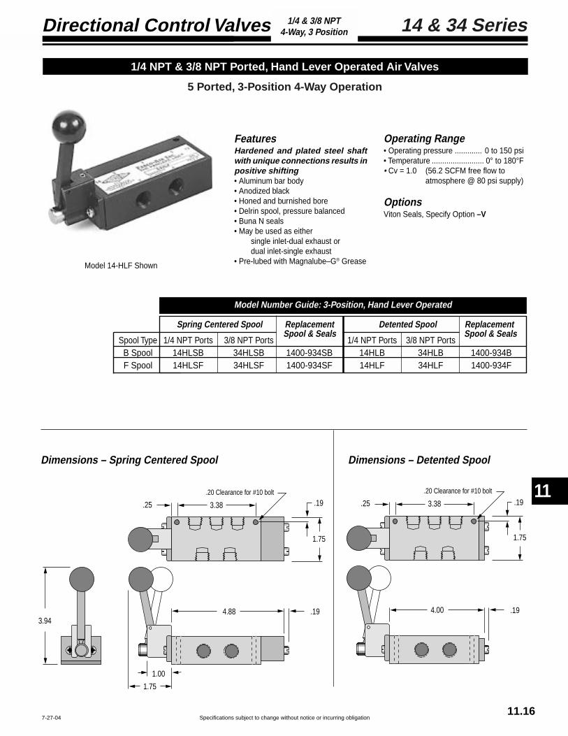
Specifications subject to change without notice or incurring obligation
11
Directional Control Valves
11
14 & 34 Series1/4 & 3/8 NPT4-Way, 3 Position
.20 Clearance for #10 bolt
3.38.25
1.75
.19
4.88
1.75
1.00
3.94.19
.20 Clearance for #10 bolt
3.38.25
1.75
.19
4.00 .19
FeaturesHardened and plated steel shaftwith unique connections results inpositive shifting• Aluminum bar body• Anodized black• Honed and burnished bore• Delrin spool, pressure balanced• Buna N seals• May be used as either
single inlet-dual exhaust ordual inlet-single exhaust
• Pre-lubed with Magnalube–G® Grease
Operating Range• Operating pressure ............. 0 to 150 psi• Temperature ......................... 0° to 180°F• Cv = 1.0 (56.2 SCFM free flow to
atmosphere @ 80 psi supply)
OptionsViton Seals, Specify Option –V
1/4 NPT & 3/8 NPT Ported, Hand Lever Operated Air Valves
5 Ported, 3-Position 4-Way Operation
Dimensions – Spring Centered Spool Dimensions – Detented Spool
7-27-04
Model 14-HLF Shown
Spring Centered Spool Replacement Detented Spool Replacement
Spool Type 1/4 NPT Ports 3/8 NPT Ports 1/4 NPT Ports 3/8 NPT PortsB Spool 14HLSB 34HLSB 1400-934SB 14HLB 34HLB 1400-934BF Spool 14HLSF 34HLSF 1400-934SF 14HLF 34HLF 1400-934F
Model Number Guide: 3-Position, Hand Lever Operated
Spool & Seals Spool & Seals
11.16

Directional Control Valves
11
Specifications subject to change without notice or incurring obligation
14 & 34 Series1/4 & 3/8 NPT4-Way, 3 Position
Features• Aluminum bar body• Anodized black• Honed and burnished bore• Delrin spool• Buna N seals• Cv = 1.0 (56.2 SCFM free flow to
atmosphere @ 80 psi supply)• Operation to 150 psi• Operating Temperature:
0°F (–18°C) to +104°F (40°C) ambient.0°F (–18°C) to +150°F (65°C) media.
• Pre-lubed with Magnalube–G® Grease• Coils & Housing information see page 11.29.
Operating RangeInternal pilot supply - standard
Inlet ........................... 50 to 150 psi
External pilot supply Option –XInlet ........................... 0 to 150 psiPilot Supply ............... 50 to 150 psi
OrderingChoose valve model number from tablebelow and add option suffixes as requiredand specify voltage/hertz.
Model 14-FFB Shown
1/4 NPT & 3/8 NPT Ported, 53 Style Solenoid Controlled, Pilot Operated Air Valves
5 Ported, 3-Position 4-Way Operation
7-28-04
Conduit Housing “C” Grommet Housing “G” Male Mini-DIN Housing “F” Replacement
Spool Type 1/4 NPT Ports 3/8 NPT Ports 1/4 NPT Ports 3/8 NPT Ports 1/4 NPT Ports 3/8 NPT PortsB Spool 14-CCB 34-CCB 14-GGB 34-GGB 14-FFB 34-FFB 1400-904BF Spool 14-CCF 34-CCF 14-GGF 34-GGF 14-FFF 34-FFF 1400-904F
Model Number Guide: 4-Way, 3-Position, Spring Centered Double Solenoid Valves
Spool & Seals
11.17

Specifications subject to change without notice or incurring obligation
11
Directional Control Valves
11
14 & 34 Series1/4 & 3/8 NPT4-Way, 3 Position
.20 Clearance for #10 bolt
.25 3.38
1.75
.19
3.886.38
1.13
2.65
1.50
.63
1.03
1.251/2 NPT
10-32 Exhaust Port
Housing can rotate 360°
1.03
10-32 Exhaust Port
1.50
.75
.63
Housing can rotate 360°
1.58.44
.88
10-32Exhaust
Port
.43
.22
(11 mm)spacing
.47.37
.571.50
Line Terminals.25 x .03
Ground Terminal.25 x .03Housing can rotate 360°
Conduit Housing "C"
Grommet Housing "G"
Male Mini-DIN Housing "F"
53 Style Solenoid Operators
Standard 53 Style OperatorThe solenoid operator is a 3-way NC valvewhich, upon receiving an electrical signal, di-rects pressure to shift the main valve spool.As standard, the operator is internally suppliedwith air pressure from the main valve inlet.
53 Style Operator with External PilotOption –XIn the following listed applications, as well asmany others, a proper air supply may not beavailable from the main valve inlet. For theseapplications, an external pilot supply port isavailable (Option –X). A proper air supply tothis port then supplies the solenoid with airpressure for piloting the main valve spool.• Dual inlet, single exhaust• Insufficient Pressure at main valve inlet• Media at main valve inlet is other than air• Extreme fast cycling
Valve Dimensions
8-26-04
1.75 1.25
.75.14 Max.
1.13
1.75 1.25
.75.14 Max.
1.13.44
1/8 NPT
11.18

Directional Control Valves
11
Specifications subject to change without notice or incurring obligation11.19
8-30-04
14, M14 & 34 Series1/4 & 3/8 NPT2, 3 & 4 Way
1/4 & 3/8 NPT Ported 53 STYLE Solenoid Controlled, Pilot Operated Air Valves2, 3 & 4 Way - 2 Position – Operation to 150 psi Air
“The Finest in Simplicity”The short stroke of the light weight Delrin® spool provides fast, positive and reliable response.
OptionsManual override
Locking . . . . . . . . . . . . . . . . . . . -MO1Non-Locking . . . . . . . . . . . . . . . -MO4
External pilot . . . . . . . . . . . . . . . . . . . . -XLight spring . . . . . . . . . . . . . . . . . . . . . -LViton seals for media compatibility . . . -VExplosion proof operators . . . . . . . . . -EP
See page 11.30Dual Inlet - Single Exhaust 4 Way
See page 11.20Note 1: Optional Flow Path.
Operating RangeInternal Pilot Supply (Standard)
Standard Spring . . . . . . . 50 to 150 psiLight Spring, Option -L . . 40 to 150 psiPilot Return (0 psi Pilot) . . 30 to 150 psi
External Pilot Supply, Option -X Inlet Pressure . . . . . . . . . . 0 to 150 psi
External Pilot Supply, Option -XStandard Spring . . . . . . . 50 to 150 psiLight Spring, Option -L . . 40 to 150 psiPilot Return (0 psi Pilot) . . 30 to 150 psi
Operating RangeInternal Pilot Supply (Standard)
Inlet . . . . . . . . . . . . . . . . . 30 to 150 psiExternal Pilot Supply, Option -X
Inlet Pressure . . . . . . . . . . 0 to 150 psiPilot Supply . . . . . . . . . . . 30 to 150 psi
SINGLE SOLENOID - PILOT RETURN MODELSA pilot return can be substituted for the standard spring return.It may be used in two manners.
1. For a pulse signal, then pilot return.2. As a constant, adjustable force, spring.Supply pilot port with a constant regulated pressure. This will actas a very constant spring against the solenoid controlled pilot signal.The pilot return should be a minimum of 30 psi below the solenoidcontrolled pressure.
To Specify, Substitute P for S in the Model Number. (Ex: 14CP-3-120/60)
SINGLE SOLENOIDTo Order Specify: Model Number from chart
OptionsVolts & Hertz (See page 11.29)
DOUBLE SOLENOIDTo Order Specify: Model Number from chart
OptionsVolts & Hertz (See page 11.29)
Simplicity
Reliability
‡2 / 3 WAY 4 WAY 4 WAY Stacking ‡2 / 3 WAY 4 WAY
ConduitHousing 14CC-3 14CC-4 M14CC-4 34CC-3 34CC-4
GrommetHousing 14GG-3 14GG-4 M14GG-4 34GG-3 34GG-4
Male Mini-DINHousing 14FF-3 14FF-4 M14FF-4 34FF-3 34FF-4
ReplacementSpool & Seals 1400-923 1400-924 1400-904 1400-923 1400-924
1/4 NPT PORTS 3/8 NPT PORTS
See pg 11.20
‡2 / 3 WAY 4 WAY 4 WAY ‡2 / 3WAY 4 WAYNormally Normally Stacking Normally NormallyClosed Open See pg 11.20 Closed Open
ConduitHousing 14CS-3 14CS-30 14CS-4 M14CS-4 34CS-3 34CS-30 34CS-4
GrommetHousing 14GS-3 14GS-30 14GS-4 M14GS-4 34GS-3 34GS-30 34GS-4
Male Mini-DINHousing 14FS-3 14FS-30 14FS-4 M14FS-4 34FS-3 34FS-30 34FS-4
ReplacementSpool & Seals 1400-913 1400-9130 1400-914 1400-904 1400-913 1400-9130 1400-914
1/4 NPT PORTS 3/8 NPT PORTS
Features• Aluminum bar stock body• Black Anodized• Honed and burnished bore• Lightweight Delrin® spool• Buna N seals• Operation to 150 psi• Operating temperature:
0°F (–18°C) to +104°F (40°C) ambient.0°F (–18°C) to +150°F (65°C) media.
• Coils & housing Information see page 11.29• Cv = 1.0• 56.2 SCFM free flow to atmosphere @ 80 psi• Prelubed with Magnalube® -G grease
‡Plug 3-Way Valvefor 2-Way Service.
‡Plug 3-Way Valvefor 2-Way Service.

Specifications subject to change without notice or incurring obligation
11
Directional Control Valves
11
11-8-04
14, M14 & 34 Series1/4 & 3/8 NPT2, 3 & 4 Way
1.751.00
.50
.14 Max.
1.13
See HousingDetailsPage 11.29
1.75 1.00.50
.14 Max.
1.13.44
1/8 NPT
.88
See HousingDetailsPage 11.29
1.751.00
.50
1.13
1.34
.31 Dia.
See HousingDetailsPage 11.29
31
2
12 10
3 Way
This 3 Way Valve may be used for any 2 Way,3 Way, Selector or Diverter service.
1210
21.78
1
1.192.09
2.88
.20 Dia. Clearancefor #10 Screw
.561.13
1.75
Primary Secondary
3
3.13
.19
.25
2 Way Function
3 1 5
2 4
1214
4 Way - 5 Port Standard: Single Inlet - Port #1 - Dual Exhaust.
14 12
2
2.53
1
1.942.84
3.63
.20 Dia. Clearancefor #10 Bolt
.56
1.34
1.75
Primary Secondary
3
3.88
.19
.251.03
4
1.13
5
3 1
214 12
5
4
Note 1: Optional Flow Path: Dual Inlet - Ports #3 & #5 - Single Exhaust. Use External Pilot Supply (Option -X).
Standard 53 STYLE Solenoid OperatorThe solenoid operator is a 3-way NC valve which, upon receiving anelectrical signal, directs a pilot pressure to shift the main valve spool.As standard, the operator is internally supplied with air pressure fromthe main valve inlet. Also see “External Pilot Supply” below.
53 STYLE Solenoid Operator with External Pilot SupplyOption -XIn the following listed applications, as well as many others, a properair supply may not be available from the main valve inlet. For theseapplications, an external pilot supply port is available (Option -X).A proper air supply to this port then supplies the solenoid with airpressure for piloting the main valve spool.
• Dual Inlet - Single Exhaust 4 Way.• Insufficient pressure at main valve inlet.• Media, at main valve inlet, other than air.• Extremely fast cycling.
53 STYLE Solenoid Operatorwith Manual OverrideThis manual override is a 3-wayNC valve that when pushed,directs pilot pressure to shift themain spool. Pressure must bepresent at main valve inlet for thisoverride to function.
TYPE SUFFIXLOCKINGPush to override; -MO1Turn to lock in;Turn back to release.NON-LOCKINGPush to override. -MO4
STACKING - PRESSURE MANIFOLDEDVersions of these 1400 Series 1/4 NPT solenoid valves with different adaptor blockscan be stacked and pressure manifolded for space and money savings. The valvebodies are bolted together with 4 through tie bolts and the pressure is manifoldedwith O-Ring seals between valves. Inlet pressure can be connected to either or bothends of the stack. Due to the fact that the pressure port, on all valve bodies, istapped on both sides, the pressure manifold can be plugged at any point within thestack. This allows you to supply the stack with two different pressures, one fromeach end.Versions of the Air Pilot, Rod Actuator, Roller Cam and Small Palm Button valvesmay be mounted in the same stack along with these solenoid valves.
7/8 Hex
.25
.50
.69 Dia.Standard Spring Return
7/8 Hex
.25
Light Spring ReturnOption -L
.25
Pilot ReturnOption -P1/8 NPT PortSee Page 11.13
Pilot Bushing
1/8 NPT
7/8 Hex
Spring Return Valves End Operator
10 Spring
12 Solenoid
10 Solenoid
12 Spring
Normally Closed
Normally Open
TO ORDERSpecify the quantity of each modeldesired, the order in which they are tobe assembled, and Brackets, if desired.
11.20
Option -Xis NOT combinablewith either Option-MO1 or -MO4

Directional Control Valves
11
Specifications subject to change without notice or incurring obligation11.21
14 & 34 Series1/4 & 3/8 NPT2, 3 & 4-Way
7-27-04
Features
• Aluminum bar stock body
• Black anodized
• Honed and burnished bore
• Lightweight Delrin® spool
• Simplicity
• Reliability
• Buna N Seals
• Corrosion resistant construction
• Operating temperature:
–5°F (–15°C) to +122°F (50°C) ambient.
–5°F (–15°C) to +122°F (50°C) media.
• Solenoid operator information
see page 11.31
• Cv = 1.0
• 56.2 SCFM Free flow to atmosphere @ 80 psi
• Plug 3 Way Valve for 2 Way service
• Prelubed with Magnalube® -G grease
Operating Ranges, psi#1 Solenoid #4 Solenoid
0.9 Watts 3.5 WattsInternal pilot supply (standard) inlet pressure
Non Spring Return . . . . . . . . . . . . . . . . . 30 to 130 ....... 30 to 145
Spring Return . . . . . . . . . . . . . . . . . . . . . 50 to 130 ....... 50 to 145
Light Spring Option -L . . . . . . . . . . . . . . 40 to 130 ....... 40 to 145
External pilot supply, Option -X inlet pressure . . . 0 to 150 ......... 0 to 150
External pilot supply, Option -X pilot supply
Non Spring Return . . . . . . . . . . . . . . . . . 30 to 130 ....... 30 to 145
Spring Return . . . . . . . . . . . . . . . . . . . . . 50 to 130 ....... 50 to 145
Light Spring Option -L . . . . . . . . . . . . . . 40 to 130 ....... 40 to 145
1/4 & 3/8 NPT Ported 58 STYLE Solenoid Controlled, Pilot Operated Air Valves2, 3 & 4 Way - 2 Position
“The Finest in Simplicity”The short stroke of the light weight Delrin® spool provides fast, positive and reliable response.
Options
External Pilot . . . . . . . . . . . . . . . . . . . -X† External Pilot and Viton Seals . . . . -XV
Light Spring . . . . . . . . . . . . . . . . . . . . -L
† Viton Seals are available in the mainvalve only, for media compatibility, andtherefore only in conjunction with ExternalPilot: –5°F (–15°C) to +122°F (50°C).

Specifications subject to change without notice or incurring obligation
11
Directional Control Valves
11
11.22
14 & 34 Series1/4 & 3/8 NPT2, 3 & 4-Way
11-8-04
3 1
4
2
Primary SolenoidManual OverridePosition Section A – A
1
3
Primary SolenoidManual OverridePosition Section B – B
31
4
2Secondary SolenoidManual OverridePosition Section A – A
1
3
Secondary SolenoidManual OverridePosition Section B – B
Primary Actuator End
1.75.88
Spring ReturnShown.50
1.00
See page 11.31for Operator Details
Secondary Actuator End
B
B
.13
See page 11.20for Body Details
3 or 4 WayValve Body
.50
Side View
Primary Actuator End
1.75.88
Spring ReturnShown
.50
1.00.14 Max.
1.00
See page 11.31for Operator Details
3 or 4 WayValve Body
Secondary Actuator End
A ASide View
.13
See page 11.20for Body Details
External PilotSupplyOption -X
1/8 NPT
.44
.88
.63
.281/8 NPT
External Pilot SupplyOption -X
58 STYLE Solenoid Valve, Model Number Code
Series14 = 1/4 NPT
34 = 3/8 NPT
Primary ActuatorF = Micro DING = Wire leadsSee page 11.31
14 F S 4 4 1 1 0 120/60—— —
Function3 = 3 Way4 = 4 WaySee page11.13For 2 Way serviceplug a 3 Way Valve
Primary SolenoidAttitude1 = Upright 90° to Body5 = Inline with Body
Primary SolenoidManual Override0 = None1 = Position #12 = Position #2‡
3 = Position #34 = Position #4‡
Secondary SolenoidAttitude0 = Other than Solenoid1 = Upright 90° to Body5 = Inline with Body
Example: 14FS-4-41100-120/601/4 NPT – Primary Actuator Solenoid with Micro DIN coil; Secondary Actuator, Spring Return – 4 Way Function3.5 Watt Solenoid; Primary Solenoid Upright position with Manual Override in Position #1; Secondary Actuator isnot a Solenoid; no Manual Override on Secondary Actuator – No Options – 120 Volt/60 Hertz.
Solenoid Watts1 = 0.9 Watts4 = 3.5 Watts
Secondary SolenoidManual Override0 = None1 = Position #12 = Position #2‡
3 = Position #34 = Position #4‡
0
Secondary ActuatorF = Micro DIN*G = Wire leads*S = Spring**P = Pilot**R = Rod**B = Small Button**L = Large Button*** See page 11.31** See pages 11.13 &
11.14 for details
Options-X = External Pilot
-XV = † External Pilot & Viton Seals-L = Light Spring
† Viton Seals are available in the mainvalve only for media compatability andtherefore only in conjunction withExternal Pilot (0° to 180°F).
‡ Solenoid Attitude #1 ONLY#1 = Upright 90° to Body
UprightSolenoid Attitude #1
(Solenoid centerline 90°to Valve Body centerline)
InlineSolenoid Attitude #5
(Solenoid centerline inlinewith Valve Body centerline)
Volts / Hertz#1 Solenoid(0.9 Watts)12 VDC24 VDC#4 Solenoid(3.5 Watts)24/60 VAC120/60 VAC12 VDC24 VDC
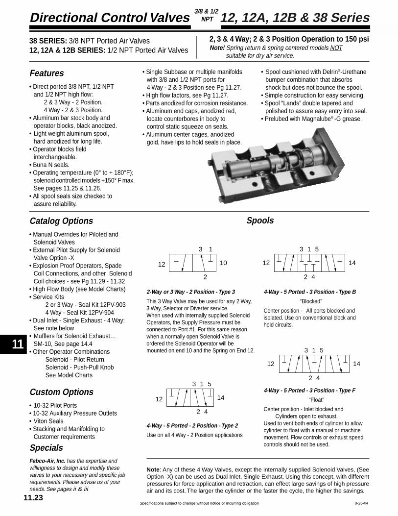
Directional Control Valves
11
Specifications subject to change without notice or incurring obligation11.23
SpecialsFabco-Air, Inc. has the expertise andwillingness to design and modify thesevalves to your necessary and specific jobrequirements. Please advise us of yourneeds. See pages ii & iii
8-26-04
12, 12A, 12B & 38 Series3/8 & 1/2
NPT
3 1 5
2 4
12 14
3 1 5
2 4
12 14
4-Way - 5 Ported - 3 Position - Type F
“Float”
Center position - Inlet blocked andCylinders open to exhaust.
Used to vent both ends of cylinder to allowcylinder to float with a manual or machinemovement. Flow controls or exhaust speedcontrols should not be used.
4-Way - 5 Ported - 3 Position - Type B
“Blocked”
Center position - All ports blocked andisolated. Use on conventional block andhold circuits.
3 1 5
2 4
12 14
3 1
2
12 10
2-Way or 3 Way - 2 Position - Type 3
This 3 Way Valve may be used for any 2 Way,3 Way, Selector or Diverter service.When used with internally supplied SolenoidOperators, the Supply Pressure must beconnected to Port #1. For this same reasonwhen a normally open Solenoid Valve isordered the Solenoid Operator will bemounted on end 10 and the Spring on End 12.
4-Way - 5 Ported - 2 Position - Type 2
Use on all 4 Way - 2 Position applications
Note: Any of these 4 Way Valves, except the internally supplied Solenoid Valves, (SeeOption -X) can be used as Dual Inlet, Single Exhaust. Using this concept, with differentpressures for force application and retraction, can effect large savings of high pressureair and its cost. The larger the cylinder or the faster the cycle, the higher the savings.
Catalog Options• Manual Overrides for Piloted and
Solenoid Valves• External Pilot Supply for Solenoid
Valve Option -X• Explosion Proof Operators, Spade
Coil Connections, and other SolenoidCoil choices - see Pg 11.29 - 11.32
• High Flow Body (see Model Charts)• Service Kits
2 or 3 Way - Seal Kit 12PV-9034 Way - Seal Kit 12PV-904
• Dual Inlet - Single Exhaust - 4 Way:See note below
• Mufflers for Solenoid Exhaust…SM-10, See page 14.4
• Other Operator CombinationsSolenoid - Pilot ReturnSolenoid - Push-Pull KnobSee Model Charts
Custom Options• 10-32 Pilot Ports• 10-32 Auxiliary Pressure Outlets• Viton Seals• Stacking and Manifolding to
Customer requirements
Spools
Features• Direct ported 3/8 NPT, 1/2 NPT
and 1/2 NPT high flow:2 & 3 Way - 2 Position.4 Way - 2 & 3 Position.
• Aluminum bar stock body andoperator blocks, black anodized.
• Light weight aluminum spool,hard anodized for long life.
• Operator blocks fieldinterchangeable.
• Buna N seals.• Operating temperature (0° to + 180°F);
solenoid controlled models +150° F max.See pages 11.25 & 11.26.
• All spool seals size checked toassure reliability.
• Single Subbase or multiple manifoldswith 3/8 and 1/2 NPT ports for4 Way - 2 & 3 Position see Pg 11.27.
• High flow factors, see Pg 11.27.• Parts anodized for corrosion resistance.• Aluminum end caps, anodized red,
locate counterbores in body tocontrol static squeeze on seals.
• Aluminum center cages, anodizedgold, have lips to hold seals in place.
• Spool cushioned with Delrin®-Urethanebumper combination that absorbsshock but does not bounce the spool.
• Simple construction for easy servicing.• Spool “Lands” double tapered and
polished to assure easy entry into seal.• Prelubed with Magnalube® -G grease.
38 SERIES: 3/8 NPT Ported Air Valves12, 12A & 12B SERIES: 1/2 NPT Ported Air Valves
2, 3 & 4 Way; 2 & 3 Position Operation to 150 psiNote! Spring return & spring centered models NOT suitable for dry air service.

Specifications subject to change without notice or incurring obligation
11
Directional Control Valves
11
11.247-28-04
12, 12A, 12B & 38 Series3/8 & 1/2
NPT
PILOT OPERATEDWhen Ordering:Specify Model Number from chart. Specify Options.(See page 11.27 & 11.28 for Dimensional Information.)
Push - Pull 2 Way - 3 Way 383-PO 123-PO 123B-PO NA(Natural Detent) 4 Way 38-PO 12-PO 12B-PO 12A-PO
Push 2 Way - 3 Way 383-PS 123-PS 123B-PS NASpring Return 4 Way 38-PS 12-PS 12B-PS 12A-PS
Push 2 Way - 3 Way 383-PA 123-PA 123B-PA NAPilot Return 4 Way 38-PA 12-PA 12B-PA 12A-PA
Push - Push 2 Way - 3 Way 383-PP 123-PP 123B-PP NAKnob Both Ends 4 Way 38-PP 12-PP 12B-PP 12A-PP
Push - PullSpring Centered 4 Way 38-PB 12-PB NA 12A-PBType B Spool
Push - PushSpring Centered 4 Way 38-PPB 12-PPB NA 12A-PPBKnob Both endsType B Spool
Push - PullSpring Centered 4 Way 38-PF 12-PF NA 12A-PFType F Spool
Push - PushSpring Centered 4 Way 38-PPF 12-PPF NA 12A-PPFKnob Both endsType F Spool
2 Position
LOCKING -MO1LOCKS IN - Does not lock OUT -MO2Does not lock IN - LOCKS OUT -MO3NON-LOCKING -MO4
Optional Manual Overrides Model Suffix
1/2 NPT3/8 NPT 1/2 NPT High Flow
SUBBASEOR
MANIFOLDMOUNTEDSee pg 11.27and Specify
Direct Ported
3 Position
Spring Return 2 Way - 3 Way 383-HLS 123-HLS 123B-HLS NA4 Way 38-HLS 12-HLS 12B-HLS 12A-HLS
Detented 2 Way - 3 Way 383-HL 123-HL 123B-HL N4 Way 38-HL 12-HL 12B-HL 12A-HL
Spring Centered 4 Way 38-HLSB 12-HLSB NA 12A-HLSBType B Spool
Spring Centered 4 Way 38-HLSF 12-HLSF NA 12A-HLSFType F Spool
Detented 4 Way 38-HLB 12-HLB NA 12A-HLBType B Spool
Detented 4 Way 38-HLF 12-HLF NA 12A-HLFType F Spool
2 Position
1/2 NPT3/8 NPT 1/2 NPT High Flow
SUBBASEOR
MANIFOLDMOUNTEDSee pg 11.27and Specify
Direct Ported
3 Position
HAND LEVER OPERATEDWhen Ordering:Specify Model Number from chart. Specify Options.(See page 11.27 & 11.28 for Dimensional Information.)
PUSH-PULL KNOB OPERATEDWhen Ordering:Specify Model Number from chart. Specify Options.(See page 11.27 & 11.28 for Dimensional Information.)
OPERATING RANGE:Inlet Presure . . . . . . . . . . . . . . . . 0 - 150 psiPilot Pressure:
Models without Spring . . . . . . . . . . . . . . . . . . 10 - 150 psi2 Position Standard Service Spring . . . . . . . 45 - 150 psi2 Position Light Service Spring (Option -L) . . 30 - 150 psi3 Position, Spring Centered . . . . . . . . . . . . . 30 - 150 psi
Single Pilot 2 Way - 3 Way 383-SP 123-SP 123B-SP NASpring Return 4 Way 38-SP 12-SP 12B-SP 12A-SP
Double Pilot 2 Way - 3 Way 383-DP 123-DP 123B-DP N4 Way 38-DP 12-DP 12B-DP 12A-DP
Double Pilot 4 Way 38-DPB 12-DPB NA 12A-DPBType B Spool
Double Pilot 4 Way 38-DPF 12-DPF NA 12A-DPFType F Spool
2 Position
1/2 NPT3/8 NPT 1/2 NPT High Flow
SUBBASEOR
MANIFOLDMOUNTEDSee pg 11.27and Specify
Direct Ported
3 Position
OPERATING RANGE: . . . . . . . . . . . . . . . . . 0 - 150 psi
OPERATING RANGE: . . . . . . . . . . . . . . . . . 0 - 150 psiStandard knob color is black.For red knob add suffix -R to Model Number.

Directional Control Valves
11
Specifications subject to change without notice or incurring obligation11.25
8-26-04
12, 12A, 12B & 38 Series3/8 & 1/2
NPT
3/8 & 1/2 NPT Ported, 53 STYLE Solenoid Controlled, Pilot Operated Air Valves2 Way, 3 Way - 2 Position — 4 Way 2 or 3 Position — Operation to 150 PSI Air
Operating Ranges, psiInternal Pilot Supply (Standard) Inlet Pressure
No Spring . . . . . . . . . . . . . . . . . . . . . . . . 10 to 150Spring: 2 Position . . . . . . . . . . . . . . . . 45 to 150
2 Position Light Service Spring, Option -L . . . . . . . . . . . . . 30 to 1503 Position . . . . . . . . . . . . . . . . 30 to 150
External Pilot Supply, Option -X:Inlet Pressure . . . . . . . . . . . . . . . . . . . . . . 0 to 150Pilot Pressure, Same as Internal Pilot Supply above.
See pages 11.27 & 11.28 fordimensional information.
LOCKING -MO1LOCKS IN - Does not lock OUT -MO2Does not lock IN - LOCKS OUT -MO3NON-LOCKING -MO4
Optional Manual Overrides Model Suffix
When Ordering:Specify Model Number from ChartSpecify OptionsSpecify Volts / HertzSee pages 11.29 & 11.30 for Solenoid Operator,Coil and Housing information.
Grommet Housing “G”
3/8 NPT 1/2 NPT 1/2NPT High Flow Sub-base/Manifold, See Pg. 11.27
Single Solenoid 2 / 3 Way, NC 383–FS 123–FS 123B–FS NASpring Return 2 / 3 Way, NO 3830–FS 1230–FS 1230B–FS NA
4 Way 38–FS 12–FS 12B–FS 12A–FS
Single Solenoid 2 / 3 Way 383–FA 123–FA 123B–FA NAPilot Return 4 Way 38–FA 12–FA 12B–FA 12A–FA
Single Solenoid 2 / 3 Way 383–FP 123–FP 123B–FP NAKnob Return 4Way 38–FP 12–FP 12B–FP 12A–FP
Double Solenoid 2 / 3 Way 383–FF 123–FF 123B–FF NA4 Way 38–FF 12–FF 12B–FF 12A–FF
Solenoid – Pilot, B Spool 4 Way 38–FAB 12–FAB NA 12A—FABSolenoid – Pilot, F Spool 4 Way 38–FAF 12–FAF NA 12A–FAF
Double Solenoid – B Spool 4 Way 38–FFB 12–FFB NA 12A—FFBDouble Solenoid – F Spool 4 Way 38–FFF 12–FFF NA 12A–FFF
2 Position
3 Position
Male Mini-DIN Housing “F”
3/8 NPT 1/2 NPT 1/2NPT High Flow Sub-base/Manifold, See Pg. 11.27
Single Solenoid 2 / 3 Way, NC 383–GS 123–GS 123B–GS NASpring Return 2 / 3 Way, NO 3830–GS 1230–GS 1230B–GS NA
4 Way 38–GS 12–GS 12B–GS 12A–GS
Single Solenoid 2 / 3 Way 383–GA 123–GA 123B–GA NAPilot Return 4 Way 38–GA 12–GA 12B–GA 12A–GA
Single Solenoid 2 / 3 Way 383–GP 123–GP 123B–GP NAKnob Return 4Way 38–GP 12–GP 12B–GP 12A–GP
Double Solenoid 2 / 3 Way 383–GG 123–GG 123B–GG NA4 Way 38–GG 12–GG 12B–GG 12A–GG
Solenoid – Pilot, B Spool 4 Way 38–GAB 12–GAB NA 12A—GABSolenoid – Pilot, F Spool 4 Way 38–GAF 12–GAF NA 12A–GAF
Double Solenoid – B Spool 4 Way 38–GGB 12–GGB NA 12A—GGBDouble Solenoid – F Spool 4 Way 38–GGF 12–GGF NA 12A–GGF
2 Position
3 Position
3/8 NPT 1/2 NPT 1/2NPT High Flow Sub-base/Manifold, See Pg. 11.27
Single Solenoid 2 / 3 Way, NC 383–CS 123–CS 123B–CS NASpring Return 2 / 3 Way, NO 3830–CS 1230–CS 1230B–CS NA
4 Way 38–CS 12–CS 12B–CS 12A–CS
Single Solenoid 2 / 3 Way 383–CA 123–CA 123B–CA NAPilot Return 4 Way 38–CA 12–CA 12B–CA 12A–CA
Single Solenoid 2 / 3 Way 383–CP 123–CP 123B–CP NAKnob Return 4Way 38–CP 12–CP 12B–CP 12A–CP
Double Solenoid 2 / 3 Way 383–CC 123–CC 123B–CC NA4 Way 38–CC 12–CC 12B–CC 12A–CC
Solenoid – Pilot, B Spool 4 Way 38–CAB 12–CAB NA 12A—CABSolenoid – Pilot, F Spool 4 Way 38–CAF 12–CAF NA 12A–CAF
Double Solenoid – B Spool 4 Way 38–CCB 12–CCB NA 12A—CCBDouble Solenoid – F Spool 4 Way 38–CCF 12–CCF NA 12A–CCF
2 Position
3 Position
Conduit Housing “C”
Operating Temperature:0°F (–18°C) to +104°F (40°C) ambient.0°F (–18°C) to +150°F (65°C) media.

Specifications subject to change without notice or incurring obligation
11
Directional Control Valves
11
11.268-26-04
12, 12A, 12B & 38 Series3/8 & 1/2
NPT
1
3
Primary SolenoidManual OverridePosition Section A – A
24
1
3
24
Secondary SolenoidManual OverridePosition Section A – A
1/8 NPT1.50
1.70
.75
External Pilot Supply Option -X
2.50
.63.31
Primary Actuator End
2.501.96
Spring ReturnShown
1.50
Secondary Actuator End
A
A
Side View
3 or 4 WayValve Body
See page 11.27for Body DetailsSee page 11.31
for Operator Details
.63
58 STYLE Solenoid Valve, Model Number Code
Primary ActuatorF = Micro DING = Wire leadsSee page 11.31
12 F S 4 5 1 0 120/60— —
Primary SolenoidAttitude5 = Inline with Body
Primary SolenoidManual Override0 = None1 = Position #12 = Position #23 = Position #34 = Position #4
Secondary SolenoidAttitude0 = Other than Solenoid5 = Inline with Body
Volts / Hertz#1 Solenoid(0.9 Watts)
12 VDC, 24 VDC
#4 Solenoid(3.5 Watts)24/60 VAC120/60 VAC
12 VDC24 VDC
Example: 12FS-45100-120/601/2 NPT, 4 Way – Primary Actuator Solenoid with Micro DIN coil;Secondary Actuator, Spring Return – 3.5 Watt; Primary SolenoidInline Attitude with Manual Override on Primary Solenoid in Position#1; Secondary Actuator is not a Solenoid; no Manual Override onSecondary Actuator – No Options – 120 Volt/60 Hertz.
Secondary SolenoidManual Override0 = None1 = Position #12 = Position #23 = Position #34 = Position #4
0
Secondary ActuatorF = Micro DIN, 2 Pos.*FB = Micro DIN
3 Position Type B*FF = Micro DIN
3 Position Type F*G = Wire leads, 2 Pos.*GB = Wire leads
3 Position Type B*GF = Wire leads
3 Position Type F*S = Spring**A = Pilot**P = Knob (Black)**PR = Knob (Red)*** See page 11.23, 11.31.** See pages 11.24 &11.28 for details.
Options-X = External Pilot
-XV = † External Pilot & Viton Seals-L = Light Spring
† Viton Seals are available in the main valveonly for media compatability and therefore onlyin conjunction withExternal Pilot [–5°F (–15°C) to +122°F (50°C)].Series: 38 = 3/8 NPT, 4 Way
383 = 3/8 NPT, 3 Way NC3830 = 3/8 NPT, 3 Way NO
12 = 1/2 NPT, 4 Way123 = 1/2 NPT, 3 Way NC
1230 = 1/2 NPT, 3 Way NO12A = 4 Way, Subbase Mount12B = 1/2 NPT, 4 Way, 2 Position High Flow
123B = 1/2 NPT, 3 Way NC, High Flow1230B = 1/2 NPT, 3 Way NO, High Flow
Solenoid Watts1 = 0.9 Watts4 = 3.5 Watts
InlineSolenoid Attitude #5
(Solenoid centerline inlinewith Valve Body centerline)
3/8 & 1/2 NPT Ported, 58 STYLE Solenoid Controlled, Pilot Operated Air Valves2 Way, 3 Way - 2 Position — 4 Way 2 or 3 Position
Spring Return and Spring Centered Models NOT suitable for dry air service#1 Solenoid #4 Solenoid0.9 Watts 3.5 Watts
Internal Pilot Supply (Standard) Inlet PressureNo Spring: . . . . . . . . . . . . . . . . . . . 10 to 130 . . . 10 to 145
Spring: 2 Position . . . . . . . . . . . 45 to 130 . . . 45 to 1452 Position Light Service Spring, Option -L . . . . . . . . . 30 to 130 . . . 30 to 1453 Position . . . . . . . . . . . 30 to 130 . . . 30 to 145
External Pilot Supply, Option -X:Inlet Pressure . . . . . . . 0 to 150 . . . . 0 to 150Pilot Pressure, Same as Internal Pilot Supply above.
Operating Ranges, psiSee pages 11.27 & 11.28 for otherdimensional information, 11.31 forsolenoid information.
Operating Temperature:–5°F (–15°C) to +122°F (50°C) ambient.–5°F (–15°C) to +122°F (50°C) media.

Directional Control Valves
11
Specifications subject to change without notice or incurring obligation11.27
12-22-06
12, 12A, 12B & 38 Series3/8 & 1/2
NPT
12 10
2
1.00
1
1.25
2.50
2.50
.27 Dia. MountingHole, 2 Places
3
3.501.75
2 WAY (Plug 3 Way)3 WAY
Spring ReturnAssemblyStandard this End
Primary Secondary
.75
1.50.31
12 14
2
1.00
1
1.25
2.50
2.50
.27 Dia. MountingHole, 2 Places
3
3.251.75
4 WAY
Spring ReturnAssemblyStandard this End
Primary Secondary
.75
1.50.31
4
5
4.00
5.00
3.63
1.63
2.13
.63
.88
3/8 or 1/2 NPT IN, CYL & EXH Ports
Basic Body Outline
Secondary
Primary
1.38
2.88
2.75
3.00
.34 Dia. Mounting Holes2 Places
5
1
3
4
2
4.25
.38
1.25
BOTTOM PORTED3/8 NPT Ports Specify 38 PV-511/2 NPT Ports Specify 12 PV-51
3.63
1.25
2.13
.63
SIDE PORTED3/8 NPT Ports Specify 38 PV-501/2 NPT Ports Specify 12 PV-50
.63
3/8 or 1/2 NPT IN & EXH Ports 3/8 or 1/2 NPT CYL Ports
Basic Body Outline
Basic Body Outline
Secondary
Primary
1.38
2.88
4.25
.382.75
3.00 .34 Dia. Mounting Holes2 Places
5
13
4
2
3.63
.63
.63
4.00
1.25
2.50
1.00
.62
Basic Body Outline
5
1
3
Secondary
Primary
5.00
4
2
4
2
4
2
4
2
1.75
3.25
1/2 NPTIN & EXH Ports
3/8 or 1/2 NPT CYL Ports on Bottom
.25
1/4-20Tie Rods
.34 Dia. Mounting Holes - 2 Each End
Station 1 Station 2 Station 3 Station 4 Etc.
.22 1.28
1.28 TYP.
.25
2.78
Valve Body & CYL Port CL
3.00 TYP.
1/4-20 x 2.00S.H.C. ValveMountingScrews
Top View
4.75
BASIC BODIES
NOTE: Any of these 4-way valves, except the internally supplied solenoid valves (seeOption -X), can be used as dual inlet, single exhaust. Using this concept, with differentpressures for force application and retraction, can effect large savings of high pressureair and its cost. The larger the cylinder or the faster the cycle, the higher the savings.
SINGLE SUBBASES
MULTIPLE MANIFOLDSMOUNT ANY COMBINATIONOF 4 WAY VALVE MODELS & PORT SIZES
To OrderSpecify Station No. - Valve Model - Manifold NumberEXAMPLE - Photo shows one unit consisting of 3 valves and manifolds:
Sta. No. 1 12A-CS-MO1 with 12 PV-65Sta. No. 2 12A-DP with 12 PV-66Sta. No. 3 12A-HL with 38 PV-65
Direct Ported3/8 or 1/2 1/2 NPT
NPT High Flow
4.1 6.2
4.1 6.22.4 NA
Subbase MountedSide or
Bottom Ported3/8 NPT 1/2 NPT
NA NA
3.1 3.72.2 2.4
2-Way – 3-Way2 Position - Type 3 Spool4-Way2 Position - Type 2 Spool
4Way
3Position
Type B Spool
TypeF
Spool
Shifted1 to 2; 1 to 4 2.4 NA 2.2 2.3Shifted2 to 3; 4 to 5 4.1 NA 3.4 3.9Centered2 to 3; 4 to 5 2.7 NA 2.6 2.8
Cv FLOW FACTORS
To OrderSpecify Valve Model No. (See pages 11.23 - 11.26)Specify Subbase Part No. listed below.EXAMPLE - Photo shows 12A-SP-MO4 with 12 PV-50
CYLINDER PORTS3/8 NPT 1/2 NPT
End Unit1/2 NPT IN & EXH
CENTER UNIT 38 PV-66 12 PV-66
38 PV-65 12 PV-65
MOUNT 4 WAY VALVEWITH ANY OPERATOR

Specifications subject to change without notice or incurring obligation
11
Directional Control Valves
11
11.287-28-04
12, 12A, 12B & 38 Series3/8 & 1/2
NPT
1.50
.50
.19
2.50
1.25
.75Pilot Port1/8 NPT .85Pilot Port
1/8 NPT
1.38Max.
.88Min.
.63
.85
2.50
.50
1.50
.75
Housing CanRotate360°
See page 11.29 forOperator Details
.85Manual Override
See page 11.29 forOperator Details
1.38Max.
.88Min.
.28Option -X
1/8 NPT External Pilot Supply
15°
4.06
1.00
15°
1.752.00
.63.25
.63
2.25
1.38 Dia.
.28 Max.
1.38Dia.
.50 Stroke
.81
1.65 .50
1.501.00
2.50
1.50
.50
.19
2.50
1.25
.75
AIR PILOT OPERATOR AIR PILOT OPERATORwith Manual Override
2 Position, Spring returnDimensions shown at thebottom of the page.
3 Position Spring Centeringis incorporated within theoperator dimensions.
53 STYLE SOLENOID OPERATORwith Manual Override and External Pilot Supply, Opption -X
53 STYLE SOLENOID OPERATOR
2 Position, Spring returnDimensions shown at thebottom of the page.
3 Position Spring Centeringis incorporated within theoperator dimensions.
The 53 STYLE solenoid operator is a 3-way valve which, upon receiving an electrical signal, directsa pilot pressure to shift the main valve spool. Unless otherwise specified, the operator is internallysupplied from the main valve inlet with pressure for piloting. If an external pilot supply is requiredspecify Suffix -X after the model number. This external pilot supply may be required; where the mediathrough the main valve is of insufficient pressure for piloting, where the media through the main valveis something other than compressed air, for 4-way dual inlet-single exhaust, or other applications.
HAND LEVEROPERATOR
PALM BUTTONOPERATOR2 Position, Spring returnDimensions shown to right.
3 Position Spring Centeringis incorporated within theoperator dimensions.
2 POSITIONSPRING RETURN,STANDARD &LIGHT SERVICE
All valve models –Standard servicespring consists of twoconcentric helical springs.Either may be removedfor “Light” Service.
3 POSITION SPRINGCENTERING OPERATORFOR HAND LEVER ONLY
58 STYLE Solenoid Operator – See page 11.26
LOCKING -MO1
LOCKS IN - Does not lock OUT -MO2
Does not lock IN - LOCKS OUT -MO3
NON-LOCKING -MO4
Note: The manual override stemphysically contacts and moves the spool.
Manual Overrides applicableto Pilot Operated or 53 Style
Solenoid Operated Valves
To SpecifyAdd Suffix to
Model Number

Directional Control Valves
11
Specifications subject to change without notice or incurring obligation11.29
8-26-04
1.50
.63
1.03
1.251/2 NPT
10-32 Exhaust Port
Housing can rotate 360°
1.03
10-32 Exhaust Port
1.50
.75
.63
Housing can rotate 360°
1.58.44
.88
10-32Exhaust
Port
.43
.22
(11 mm)spacing
.47.37
.571.50
Line Terminals.25 x .03
Ground Terminal.25 x .03Housing can rotate 360°
53 STYLE Stocked Coils and Housings
Conduit Housing “C” and Grommet Housing “G”Non-molded – Class A 221°F (105°C) Rating,
24" Leads of AWG #18 Wire.Stocked Voltages:
24, 120 and 240 Volt at 50 or 60 Hertz;6, 12 and 24 Volt DC;Others available, see Options on page 11.30.
Temperature Range:0°F (–18°C) to + 104°F (+40°C), ambient.0°F (–18°C) to + 150°F (+65°C), media.
Typical Response Times:AC 4 to 8 milliseconds to open or close;DC 9 to 15 milliseconds to open;DC 5 to 12 milliseconds to close.
To compute current requirements (±15%) divide factor shown below by voltage
Male Mini-DIN Housing “F”Molded – Water Tight - Class A 221°F (105°C) Coil Rating.European (DIN) Style – 11 mm spacing.See page 11.30 for connectors or contact your local distributor for additional choices.Can also be connected with individual .25" quick connect terminals.Stocked Voltages:
24, 120 and 240 Volt at 50 or 60 Hertz;12 and 24 Volt DC;Others available, see Options on page 11.30.
Temperature Range:0°F (–18°C) to + 104°F (+40°C), ambient.0°F (–18°C) to + 150°F (+65°C), media.
Typical Response Times:AC 4 to 8 milliseconds to open or close;DC 9 to 15 milliseconds to open;DC 5 to 12 milliseconds to close.
To compute current requirements (±15%) divide factor shown below by voltage.
AC Volts, 60 Hertz DC Volts
Inrush, AmpFunction Inrush, Amp Holding, Amp or Holding, Amp
2 Way NC 14.4 ÷ Volts 9.7 ÷ Volts 10.4 ÷ Volts
2 Way NO
3 Way NC or NO
Examples 15.2 ÷ 120 = 11.8 ÷ 120 = 10.4 ÷ 12 =.13 Amp .10 Amp .87 Amp
15.2 ÷ Volts 11.8 ÷ Volts 10.4 ÷ Volts
AC Volts, 60 Hertz DC Volts
Inrush, AmpFunction Inrush, Amp Holding, Amp or Holding, Amp
2 Way NC 13.2 ÷ Volts 7.8 ÷ Volts
2 Way NO
3 Way NC or NO
Examples 15.2 ÷ 120 = 9.0 ÷ 120 = 7.2 ÷ 12 =.13 Amp .08 Amp .60 Amp
15.2 ÷ Volts 9.0 ÷ Volts7.2 ÷ Volts
Conduit Housing “C”
Grommet Housing “G”
Male Mini-DIN Housing “F”
Spade terminals accept miniaturerectangular quick connect socket(Female DIN style connector, 11 mmspacing) or individual .25" quickconnect terminals.
Solenoid, Coil and Housing Information 53 Style
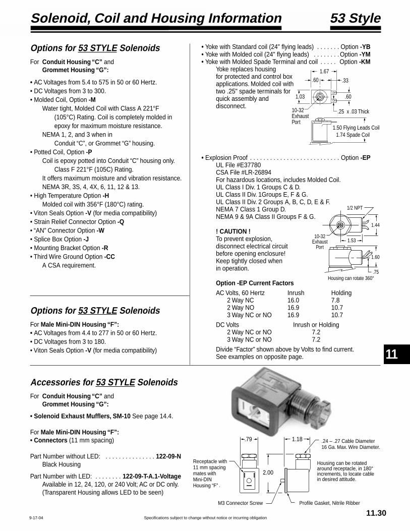
Specifications subject to change without notice or incurring obligation
11
Directional Control Valves
11
11.309-17-04
Profile Gasket, Nitrile Ribber
Housing can be rotated around receptacle, in 180° increments, to locate cable in desired attitude.
M3 Connector Screw
1.18
2.00
Receptacle with 11 mm spacingmates withMini-DIN Housing “F”
.24 – .27 Cable Diameter16 Ga. Max. Wire Diameter.
.79
.
Accessories for 53 STYLE SolenoidsFor Conduit Housing “C” and
Grommet Housing “G”:
• Solenoid Exhaust Mufflers, SM-10 See page 14.4.
For Male Mini-DIN Housing “F”:• Connectors (11 mm spacing)
Part Number without LED: . . . . . . . . . . . . . . . 122-09-NBlack Housing
Part Number with LED: . . . . . . . . 122-09-T-A.1-VoltageAvailable in 12, 24, 120, or 240 Volt; AC or DC only.(Transparent Housing allows LED to be seen)
Options for 53 STYLE SolenoidsFor Male Mini-DIN Housing “F”:• AC Voltages from 4.4 to 277 in 50 or 60 Hertz.• DC Voltages from 3 to 180.• Viton Seals Option -V (for media compatibility)
Options for 53 STYLE SolenoidsFor Conduit Housing “C” and
Grommet Housing “G”:
• AC Voltages from 5.4 to 575 in 50 or 60 Hertz.• DC Voltages from 3 to 300.• Molded Coil, Option -M
Water tight, Molded Coil with Class A 221°F(105°C) Rating. Coil is completely molded inepoxy for maximum moisture resistance.
NEMA 1, 2, and 3 when inConduit “C”, or Grommet “G” housing.
• Potted Coil, Option -PCoil is epoxy potted into Conduit “C” housing only.
Class F 221°F (105C) Rating.It offers maximum moisture and vibration resistance.NEMA 3R, 3S, 4, 4X, 6, 11, 12 & 13.
• High Temperature Option -HMolded coil with 356°F (180°C) rating.
• Viton Seals Option -V (for media compatibility)• Strain Relief Connector Option -Q• “AN” Connector Option -W• Splice Box Option -J• Mounting Bracket Option -R• Third Wire Ground Option -CC
A CSA requirement.
• Yoke with Standard coil (24" flying leads) . . . . . . . Option -YB• Yoke with Molded coil (24" flying leads) . . . . . . . . Option -YM• Yoke with Molded Spade Terminal and coil . . . . . Option -KM
Yoke replaces housingfor protected and control boxapplications. Molded coil withtwo .25" spade terminals forquick assembly anddisconnect.
• Explosion Proof . . . . . . . . . . . . . . . . . . . . . . . . . . . Option -EPUL File #E37780CSA File #LR-26894For hazardous locations, includes Molded Coil.UL Class I Div. 1 Groups C & D.UL Class II Div. 1Groups E, F & G.UL Class II Div. 2 Groups A, B, C, D, E & F.NEMA 7 Class 1 Group D.NEMA 9 & 9A Class II Groups F & G.
! CAUTION !To prevent explosion,disconnect electrical circuitbefore opening enclosure!Keep tightly closed whenin operation.
Option -EP Current FactorsAC Volts, 60 Hertz Inrush Holding
2 Way NC 16.0 7.82 Way NO 16.9 10.73 Way NC or NO 16.9 10.7
DC Volts Inrush or Holding2 Way NC or NO 7.23 Way NC or NO 7.2
Divide “Factor” shown above by Volts to find current.See examples on opposite page.
Solenoid, Coil and Housing Information 53 Style
1.53
1.60
1.44
.75Housing can rotate 360°
1/2 NPT
10-32Exhaust
Port
.60
1.67
.33
.60
.25 x .03 Thick
1.50 Flying Leads Coil1.74 Spade Coil
10-32Exhaust Port
1.03
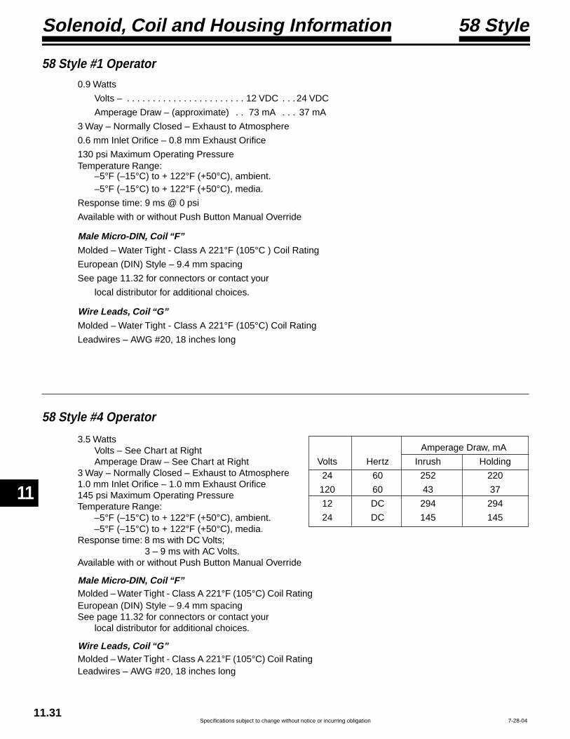
Directional Control Valves
11
Specifications subject to change without notice or incurring obligation11.31
7-28-04
58 Style #1 Operator
58 Style #4 Operator
Amperage Draw, mA
Volts Hertz Inrush Holding
24 60 252 220
120 60 43 37
12 DC 294 294
24 DC 145 145
3.5 WattsVolts – See Chart at RightAmperage Draw – See Chart at Right
3 Way – Normally Closed – Exhaust to Atmosphere1.0 mm Inlet Orifice – 1.0 mm Exhaust Orifice145 psi Maximum Operating PressureTemperature Range:
–5°F (–15°C) to + 122°F (+50°C), ambient.–5°F (–15°C) to + 122°F (+50°C), media.
Response time: 8 ms with DC Volts;3 – 9 ms with AC Volts.
Available with or without Push Button Manual Override
Male Micro-DIN, Coil “F”Molded – Water Tight - Class A 221°F (105°C) Coil RatingEuropean (DIN) Style – 9.4 mm spacingSee page 11.32 for connectors or contact your
local distributor for additional choices.
Wire Leads, Coil “G”Molded – Water Tight - Class A 221°F (105°C) Coil RatingLeadwires – AWG #20, 18 inches long
0.9 Watts
Volts – . . . . . . . . . . . . . . . . . . . . . . . 12 VDC . . . 24 VDC
Amperage Draw – (approximate) . . 73 mA . . . 37 mA
3 Way – Normally Closed – Exhaust to Atmosphere
0.6 mm Inlet Orifice – 0.8 mm Exhaust Orifice
130 psi Maximum Operating PressureTemperature Range:
–5°F (–15°C) to + 122°F (+50°C), ambient.–5°F (–15°C) to + 122°F (+50°C), media.
Response time: 9 ms @ 0 psi
Available with or without Push Button Manual Override
Male Micro-DIN, Coil “F”Molded – Water Tight - Class A 221°F (105°C ) Coil Rating
European (DIN) Style – 9.4 mm spacing
See page 11.32 for connectors or contact your
local distributor for additional choices.
Wire Leads, Coil “G”Molded – Water Tight - Class A 221°F (105°C) Coil Rating
Leadwires – AWG #20, 18 inches long
Solenoid, Coil and Housing Information 58 Style

Specifications subject to change without notice or incurring obligation
11
Directional Control Valves
11
11.328-26-04
Flat Gasket, Nitrile Ribber
Housing can rotate around receptacle, in 90° increments, to locate cable in desired attitude.
M3 Connector Screw
1.02
1.38
.61
Receptacle with 9.4 mm spacingmates withMicro-DIN Coil “F”
.26 Max. Cable Dia.18 Ga. Max. Wire Dia.
Exhaust Port.25
.38 Dia.
1.36
.44
.63
.30
.27
.19
.19
1.89
Ground Terminal.14 x .02
.37 (9.4mm) Spacing
Line Terminal.11 x .02Exhaust Port
1.06
.44
.63
1.89
AWG #2018" Long
Exhaust Port Exhaust Port.25
.38 Dia.
58 Style[#1 (0.9 Watts), or #4 (3.5 Watts)] Operatorwith Male Micro-DIN Coil “F” andwithout Manual Operator.
Part Number without LED: . . . . . . . . . . . . . . . . . . 192-07-NBlack Housing
Part Number with LED: . . . . . . . . . 192-07-T-A.1-VoltageAvailable in 12 or 24 Volt, AC or DC only.(Transparent Housing allows LED to be seen)
58 Style[#1 (0.9 Watts), or #4 (3.5 Watts)] Operatorwith Male Micro-DIN Coil “F” andwith Manual Operator.
58 Style[#1 (0.9 Watts), or #4 (3.5 Watts)] Operatorwith Leadwire Coil “G” andwithout Manual Operator.
58 Style[#1 (0.9 Watts), or #4 (3.5 Watts)] Operatorwith Leadwire Coil “G” andwith Manual Operator.
Connectors(9.4 mm Spacing)
Solenoid, Coil and Housing Information 58 Style

12
Needle & Flow Control Valves
Specifications subject to change without notice or incurring obligation12.1 10-17-06
Air Service to 150 psi-30° to + 250°F Miniature
.50Max.
.13
.87.72
.19
.75
.50
1.00.31 10-32 Ports
.Clearance for #6 Screws, 2 places
.50 Max.
7/16 Hex1.09
15/32-32Thread
.63
Nuts: 9/16 Hexx .09 Thick.19 Max.PanelThickness
#10-32 Female
1/8 NPT
.50 Max.
.94
7/16 Hex
.28
.16#10-32.31
Dia..06
.25 Max.
.81 7/16 Hex
.22
.13
.06 #10-32.31Dia.
.50 .25
Needle Valve• Controls both ways• Full range adjustability• Knurled control knob• Dual tapered needle• Gasket included (GA-10)• Brass construction• Buna-N seal• For infinite positioning use
“Thread Sealant - no gasketassembly” (See page 14.1)
FN-32Options:Slotted knurled knob -KSScrewdriver slot(MN-32 type) -S
Locknut on stem -LAdaptor knob -BViton seal -V
Needle Valve• Controls both ways• Full range adjustability• Screwdriver slot• Dual tapered needle• Gasket included (GA-10)• Brass construction• Buna-N seal• For infinite positioning use
“Thread Sealant - no gasketassembly” (See page 14.1)
MN-32Options:Knurled knob(FN-32 type) -KSlotted knurled knob -KSLocknut on stem -LAdaptor knob -BViton seal -V
Panel Mount Needle Valve• Controls both ways• Full range adjustability• Knurled control knob• Dual tapered needle• Brass construction• Buna-N seal• Mount in panel or directly
into valve or cylinder port• 2 Nuts & 1 Washer included
FN-18Options:Slotted knurled knob -KSScrewdriver slot(MN-32 type) -S
Locknut on stem -LAdaptor knob -BWithout panel nuts -CViton seal -V
Flow Control Valve• Controls one way –
Full flow return• Full range adjustability• Knurled control knob• Dual tapered needle• Brass construction• Buna-N seals• For quick exhaust order without
spring, Option -W• Flow rates - see page 12.5
FC-32Options:Slotted knurled knob -KSScrewdriver slot(MN-32 type) -S
Locknut on stem -LAdaptor knob -BViton seals -VWithout spring -W
Adapter Knob• Allows the incorporation of
decorative knobs with .25" I.D.and set screw
Option -BOrder any ControlValve with this Knobby specifying Option -B

12
Needle & Flow Control Valves
Specifications subject to change without notice or incurring obligation 12.24-20-04
Air Service to 150 psi0° to + 180°F Micro-Fine™
.63 Dia..75
1.10 Maximum
.34 .79
1.69
3/4-16Thread2 Nuts:7/8 Hexx .13 Thick
.75 Dia.
3/4 Hex
10-32 Ports(Random Rotation Relationship)
BA
Symbol
A
B
SCFHSCFM
0 20 40 60 80 1000 .33 .67 1.00 1.33 1.67
KN
OB
TU
RN
S
0
1
2
3
4
5
6
7
8
9
FLOW @80 psi
.63 Dia..75
1.10 Maximum
.34 .79
1.25
3/4-16Thread2 Nuts:7/8 Hexx .13 Thick
.75 Dia.
5/8 Hex
10-32 Ports
Symbol
NV-55Needle Valve
FC-55Flow Control Valve
NV-55Weight = 2.7 oz.
FC-55Weight = 4.0 oz.
These precision machined valves are designedand manufactured to provide Micro-Fine™control of gasses and liquids. They have amicrometer pitch (40 threads per inch) adjust-ing thread and precision machined taperedneedle and seat. They are available as needlevalves and flow control valves.
Features
The precision is shown on the chart below.You can see how close the actual flow (plotteddots) approaches a straight line. Also notethat it takes 9 full turns to go from bubble tightshut-off to its full flow of 100 Standard CubicFeet per Hour (1.67 SCFM) at 80 psi inlet.
• Linear control to 100 SCFH @ 80 psi (see chart below).• Micrometer pitch adjusting thread, 40 TPI, .025 per turn.• 10-32 ports.• Stainless steel needle - 3° taper.• Friction O-Ring provides “stay-put” adjustment.• Knurled adjusting knob with set screw lock.• White Delrin® knob, colors available.• Brass body.• Buna-N seals.• Operating temperature (0° to + 180°F).• Panel mounting standard.• 2 Brass panel mount nuts included as standard.• 100% tested, “Bubble-tight” shut-off.• Air or Hydraulic service to 150 psi.
Options• Viton seals for media compatibility, specify Option -V.

12
Needle & Flow Control Valves
Specifications subject to change without notice or incurring obligation
Swivel, Port Mounted
12.3
Port Mounted, Swivel, Brass Body Flow Controls (See next page 12.4)• Full 360° Swivel • Easy Disassembly for Maintenance • Pre-applied Thread Sealant
Port Mounted, Swivel, Molded Body Flow Controls.
• Full 360° Swivel • Compact Size • Pre-applied Thread Sealant
SpecificationsMale Sizes: #10-32, 1/8 NPT, 1/4 NPT
Female NPT or Instant Tube Connections:10-32, 1/8 NPT, 1/4 NPT, 5/32" T, 1/4" T, 3/8" T
Choice of controlled flow direction:• Valve mount – Meter In• Cylinder Mount – Meter Out
See page 12.5 for Flow Rates
Operating Pressure to 150 psi Air Service Only
Temperature Range –25° to +250° F
SpecificationsMale Sizes: #10-32, 1/8 NPT, 1/4 NPT, 3/8 NPT
Female Instant Tube Connections:5/32" T, 1/4" T, 3/8" T
Controlled Flow Direction: Meter Out Only
Operating Pressure to 150 psi Air Service Only
Temperature Range 0° to +160° F
Model No. Description A B max C Flow (Cv)PK-82010 5/32 tubing x 10-32 miniature 0.68 0.45 1.08 0.05PK-82012 5/32 tubing x 1/8 NPT 1.05 0.75 1.25 0.13PK-82014 5/32 tubing x 1/4 NPT 1.17 0.75 1.37 0.13PK-82040 1/4 tubing x 10-32 0.95 0.75 1.30 0.08PK-82042 1/4 tubing x 1/8 NPT 1.05 0.75 1.30 0.13PK-82044 1/4 tubing x 1/4 NPT 1.17 0.75 1.40 0.13PK-82046 1/4 tubing x 3/8 NPT 1.38 0.92 1.75 0.27PK-82064 3/8 tubing x 1/4 NPT 1.34 0.92 1.70 0.27PK-82066 3/8 tubing x 3/8 NPT 1.38 0.92 1.75 0.27
Knob Adjustable Valves Recessed Screw Adjustable ValvesModel No. Description A B max C Flow (Cv)PR-82110 5/32 tubing x 10-32 miniature 0.68 0.11 1.08 0.05PR-82112 5/32 tubing x 1/8 NPT 1.05 0.20 1.25 0.13PR-82114 5/32 tubing x 1/4 NPT 1.17 0.20 1.37 0.13PR-82140 1/4 tubing x 10-32 0.95 0.20 1.30 0.08PR-82142 1/4 tubing x 1/8 NPT 1.05 0.20 1.30 0.13PR-82144 1/4 tubing x 1/4 NPT 1.17 0.20 1.40 0.13PR-82146 1/4 tubing x 3/8 NPT 1.38 0.28 1.75 0.27PR-82164 3/8 tubing x 1/4 NPT 1.34 0.28 1.70 0.27PR-82166 3/8 tubing x 3/8 NPT 1.38 0.28 1.75 0.27
PC1-K PC2-A PC4-L
C
A
B
C
A
B
C
A
B
C
A
B
4-20-98
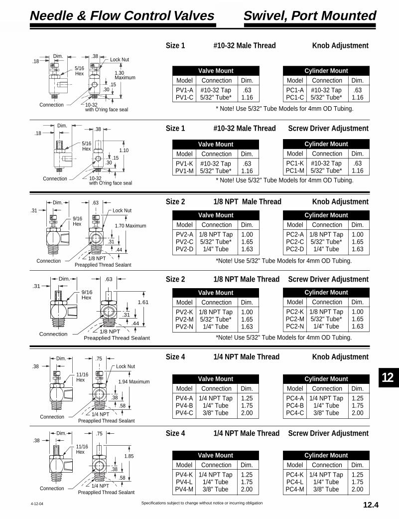
12
Needle & Flow Control Valves
Specifications subject to change without notice or incurring obligation 12.44-12-04
Swivel, Port Mounted
Dim.
Lock Nut
Preapplied Thread SealantConnection 1/8 NPT
.31
.63
.31
.44
9/16Hex 1.70 Maximum
Preapplied Thread SealantConnection 1/8 NPT
Dim..31
.63
.31
.44
9/16Hex
1.61
Dim.
Lock Nut
Preapplied Thread SealantConnection 1/4 NPT
.38
.75
.38
.58
11/16Hex 1.94 Maximum
Preapplied Thread SealantConnection 1/4 NPT
Dim..38
.75
.38
.58
11/16Hex
1.85
Size 1 #10-32 Male Thread Knob Adjustment
* Note! Use 5/32" Tube Models for 4mm OD Tubing.
Size 1 #10-32 Male Thread Screw Driver Adjustment
Size 2 1/8 NPT Male Thread Knob Adjustment
Size 2 1/8 NPT Male Thread Screw Driver Adjustment
Size 4 1/4 NPT Male Thread Knob Adjustment
Size 4 1/4 NPT Male Thread Screw Driver Adjustment
Valve MountModel Connection Dim.
PV4-K 1/4 NPT Tap 1.25PV4-L 1/4" Tube 1.75PV4-M 3/8" Tube 2.00
Cylinder MountModel Connection Dim.
PC4-K 1/4 NPT Tap 1.25PC4-L 1/4" Tube 1.75PC4-M 3/8" Tube 2.00
Valve MountModel Connection Dim.
PV4-A 1/4 NPT Tap 1.25PV4-B 1/4" Tube 1.75PV4-C 3/8" Tube 2.00
Cylinder MountModel Connection Dim.
PC4-A 1/4 NPT Tap 1.25PC4-B 1/4" Tube 1.75PC4-C 3/8" Tube 2.00
Valve MountModel Connection Dim.
PV2-K 1/8 NPT Tap 1.00PV2-M 5/32" Tube* 1.65PV2-N 1/4" Tube 1.63
Cylinder MountModel Connection Dim.
PC2-K 1/8 NPT Tap 1.00PC2-M 5/32" Tube* 1.65PC2-N 1/4" Tube 1.63
Valve MountModel Connection Dim.
PV2-A 1/8 NPT Tap 1.00PV2-C 5/32" Tube* 1.65PV2-D 1/4" Tube 1.63
Cylinder MountModel Connection Dim.
PC2-A 1/8 NPT Tap 1.00PC2-C 5/32" Tube* 1.65PC2-D 1/4" Tube 1.63
Valve MountModel Connection Dim.
PV1-K #10-32 Tap .63PV1-M 5/32" Tube* 1.16
Cylinder MountModel Connection Dim.
PC1-K #10-32 Tap .63PC1-M 5/32" Tube* 1.16
Valve MountModel Connection Dim.
PV1-A #10-32 Tap .63PV1-C 5/32" Tube* 1.16
Cylinder MountModel Connection Dim.
PC1-A #10-32 Tap .63PC1-C 5/32" Tube* 1.16
*Note! Use 5/32" Tube Models for 4mm OD Tubing.
*Note! Use 5/32" Tube Models for 4mm OD Tubing.
* Note! Use 5/32" Tube Models for 4mm OD Tubing.
Dim..18
5/16Hex
.38
1.10
.30.15
10-32with O'ring face seal
Connection
Dim..18
5/16Hex
.38
1.30Maximum
.30.15
10-32with O'ring face seal
Connection
Lock Nut
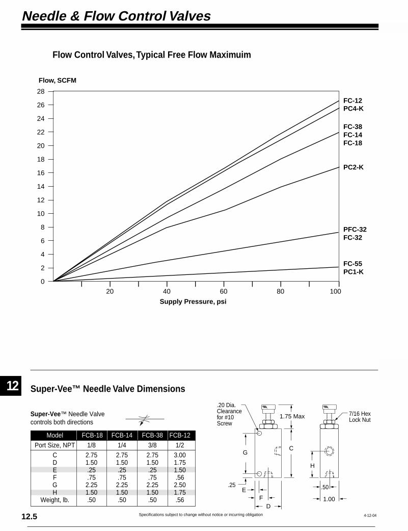
12
Needle & Flow Control Valves
Specifications subject to change without notice or incurring obligation12.5 4-12-04
0
2
4
6
8
10
12
14
16
18
20
22
24
26
28
Flow, SCFM
Supply Pressure, psi
20 40 60 80 100
FC-55PC1-K
PFC-32FC-32
PC2-K
PC4-K
FC-38FC-14FC-18
FC-12
C
H
FE
D
.50
1.00
1.75 Max 7/16 HexLock Nut
.20 Dia.Clearancefor #10Screw
G
.25
Super-Vee™ Needle Valve Dimensions
Super-Vee™ Needle Valvecontrols both directions
Model FCB-18 FCB-14 FCB-38 FCB-12
Port Size, NPT 1/8 1/4 3/8 1/2
C 2.75 2.75 2.75 3.00D 1.50 1.50 1.50 1.75E .25 .25 .25 1.50F .75 .75 .75 .56G 2.25 2.25 2.25 2.50H 1.50 1.50 1.50 1.75
Weight, lb. .50 .50 .50 .56
Flow Control Valves, Typical Free Flow Maximuim

12
Needle & Flow Control Valves
Specifications subject to change without notice or incurring obligation 12.64-20-04
CG
FE
D
J
.50
1.00
1.75 Max
H
7/16 HexLock Nut
.27 Dia.Clearancefor 1/4"Screw
A
B
BA
Annular ringFlow Area
HoleTapered Needle
Control Bushing
“Bubble Tight” Shut-Off Seal Control Bushing Seal
Large Orifice Created by Angled “V” Notch
FCB-14
FC-14
Super-Vee™
Super-Vee™ Flow Controlcontrols one direction –Free flow return
Model FC-18 FC-14 FC-38 FC-12
Port Size, NPT 1/8 1/4 3/8 1/2
C 2.75 2.75 2.75 3.25D 2.00 2.00 2.00 2.50E .38 .38 .38 .50F 1.50 1.50 1.50 1.88G 1.38 1.38 1.38 2.50H 1.50 1.50 1.56 2.06J 1.00 1.00 1.00 .38
Weight, lb. .63 .63 .63 .83
The unique design of the Super-Vee™ con-trol results in SUPER adjustability from fullflow to bubble tight shut-off with an orifice thatprovides precise repetition of selected flowrates.
A straight stem with an angled “V” Notch fitssnugly into a control bushing. The actual con-trol orifice is one large hole compared to thenarrow annular ring (see drawing below) thatis the orifice formed by the typical taperedneedle in a round hole.When controlling air or liquid at a very low ratewith a tapered needle and hole, the annular
ring becomes minute and will catch even verysmall dirt particles and create blockage. Thischanges the orifice size and causes the flow rateto vary. However, the Super-Vee™s large holeorifice will allow much larger particles to flowthrough freely; thus not changing flow rate.
Even with this large orifice advantage, we recom-mend that when you require extremely fine con-trol and exact repetition every cycle, that youincorporate a filter on each side of the Super-Vee™ to assure that no particles can reach the“V” Notch orifice.
• Air service to 150 psi• Hydraulic service to 150 psi• No tapered needles• Delrin® control bushing• Repairable• Knurled adjusting knob• Adjustment lock nut• Quality design• Quality construction• Buna-N seals
• Operating temperature (0° to + 180°F)• Black anodized aluminum body• Stainless steel stem• Stainless steel spring (“FC-” Models)• Brass cartridge and poppet• Corrosion resistant construction• “Bubble-tight” shut-off
Options• Viton seals for media compatibility,
Option -V
Super-Vee™ conceptSuperior consistency
Super-Vee™ Flow Control Dimensions
Typical Needle & Hole Concept
Features
Air or Hydraulicto 150 psi

13
Special Purpose Valves
Specifications subject to change without notice or incurring obligation13.1 10-26-04
One-Shot (Pulse)
.75
1.25
2.31 OS-13.81 OS-3
1.56
.78.44
.28.97
INEX1/8 NPT Ports
2 Mounting Holesfor #10 Screws
.16
Materials:Body, Aluminum, UnanodizedCap, BrassSpool, Aluminum
IN EXH
CYL
Model No. OS-1 & OS-3 1/8 NPT Ports
OperationWhen the incoming signal
is applied to the IN port, thespool is immediately shifted,allowing the pressure to andthrough the CYL port, be-coming the output signal.Pressure then bleeds across an orificethrough the piston head. When pressure is equal onboth sides of the piston head there is a force unbalance on thespool. This force unbalance returns the spool to its originalposition. In this position the incoming signal is blocked and theCYL is connected to the EXH, in turn venting the output signal.
Before the valve can produce another output signal it must bereset. This is accomplished when the input signal is removedfrom the IN port and the pressure behind the piston bleeds backthrough the orifice and drops to zero psi. This also self cleans theorifice every cycle. The next incoming signal can then produceanother output signal.
NOTE! The incoming signal MUST be of sufficient pressureand volume to shift the spool before bleeding across the orificeand balancing out.
SizingModel Weight
Number Port Size Oz.OS-1 3/4 1 1/8 NPT 3.1OS-3 1-1/2 2 1/8 NPT 4.8
ApproximatePulse Time,
Seconds@80 psi
ApproximateResetTime,
Seconds@80 psi
OS-1
Symbol
Features• One moving part.• Buna-N seals.• Pulse time preset
at factory.(See Model Chart)
• Shorter pulse can befield set with ordinarysewing needle.
• Can be cleaned orrepaired withoutremoving from installation.
• Spool action can beobserved for troubleshooting circuit.
• Operating pressure: 45 to 150 psi.
• Operating temperature: 0° to + 180°F.
• No springs.• Self-cleaning orifice.
Applications• Signal Conversion - Pulse, to convert a constant or maintainedsignal from a limit valve or other source to a pulse or momentarysignal for a double piloted valve or other device. This allows thedouble piloted valve to be shifted back even though the originat-ing limit valve is still held open. See sequencing circuit on page13.4.
• Single Cycle, to convert a signal from a hand or foot control toa pulse signal. This allows only one cycle of the circuit even if theoperator holds the starting device on. The operator must releasethe starting device to reset the one-shot / pulse valve and thenreactuate to achieve the next cycle. See pressure sensing circuiton page 13.4.
• Open End Blast, to provide a pulse of air through a nozzle ortube for automatic part blow off or chip removal.
Dimensions
This valve provides a momentary (pulse) output at its cylinder port when pressure is applied at its inlet. No additional flow is possibleuntil pressure at the inlet is removed, reset time allowed, and pressure reapplied. Reset time is slightly longer than output pulse time.

13
Special Purpose Valves
Specifications subject to change without notice or incurring obligation 13.25-21-04
Adjustable, Interval Delay
IN EXH
CYLOS-1Modified
Adjustable VolumeChamber
Volume ChamberDump Valve
Volume Chamber VentDo Not Block
Symbol
Interval DelayUpon application of an input signal (pressure) there is an output
signal for an adjustable time, within ranges shown. At the end of thistime the output signal is vented. Another output is not possible untilthe input is vented to atmosphere for 1 second minimum (resettime). Another input signal can then be applied for another outputsignal.
The time proven Fabco-Air OS-1 Pulse Valve (see page 13.1)is the basis of this unique, all pneumatic, adjustable, IntervalDelay. The OS-1 is mounted on and connected to an adjustablevolume chamber. When the incoming signal is applied to the IN portof the OS-1, its spool is immediately shifted, and the chamber dumpvalve is closed. This allows pressure to and through the CYL port,becoming the output signal. Pressure then bleeds across an orificethrough the piston head and into the adjustable volume chamber.When pressure is equal on both sides of the piston head there isa force unbalance on the spool. This force unbalance returns thespool to its original position. In this position the incoming signal isblocked and CYL is connected to EXH, in turn venting the outputsignal. Adjusting the volume of the chamber adjusts the length ofthe output signal.
Before the valve can produce another signal it must be reset.Resetting is accomplished by removing the input signal from andventing the IN for 1 second minimum. This allows pressure behindthe piston to bleed back through the orifice and opens the chamberdump valve. All volume behind the piston then bleeds down to zeropsi. This action self cleans the orifice at every cycle. The nextincoming signal can then produce another output signal.
NOTE! The incoming signal MUST be of sufficient pressure andvolume to shift the spool before bleeding across the orifice andbalancing out.
Model OS-5 1 to 6 second output signal
Model OS-6 3 to 8 second output signal
Model OS-7 6 to 13 second output signal
On
OffPressure at IN
On
OffOutput at CYL
Time
Reset
Adjustable Output Signal
.80___3.30
4.691/8 NPTPorts
3.50.591.13 .19
1.59
1.50.19
2.25
1.88
EXHIN
.691.41
Adjusting Knob, 3/4 Dia.
#10-24 x .25 Dp.Mounting Holes, 4 Places
9/16 HexAdjustmentLock Nut
CYL
Chamber Vent Do Not Block
Dimensions
Features• One moving part.
• Buna-N seals.
• Repeatability: ± 5% of Output signal.
• Can be cleaned or repaired without removing frominstallation.
• Spool can be observed for circuit trouble shooting.
• Operating pressure: 45 to 150 psi.
• Operating temperature: 0° to + 180°F.
• No springs.
• Self-cleaning orifice.
• 1/8 NPT ports.

13
Special Purpose Valves
Specifications subject to change without notice or incurring obligation13.3 5-21-04
OUT
Vent
.26 Maximum
1.75
2.692.25
.25
Vent adjustmentScrew & Locknut
IN.941.25
.25
RV-1 1/8 NPT PortsRV-2 1/4 NPT Ports
2 Mounting Holes for #10 Screws
1/2 Hex
.56 Maximum
.75.38
Vent
OUT
IN
Pressure Sensing/Sequence
“RV” Valve FunctionThe “RV”, with its unique poppet type seal, senses the pressure being
applied and opens at a pre-adjusted point to provide a pilot signal for circuitcontrol. Because the output force of a cylinder is a direct function of pressuretimes area, the “RV” provides direct and precision adjustable force sensing.
If the application requires that a predetermined force be applied to anobject at a point that may vary in physical dimension (such as riveting,crimping, etc.) the “RV” is the control to use. It assures that the predeter-mined force (pressure) is applied. If the system pressure should drop belowthe “RV's” set point, the valve cannot open. Therefore the cycle will stop andwait for the required pressure rather than produce an unacceptable rivet orcrimp. When the required pressure is restored the cycle will continue.
If the application requires that a particular physical point is reached by thecylinder then a position sensor, such as a limit valve, Hall Effect sensor,Reed Switch, limit switch, or other device should be used.
Features• Simple - One moving part
• Corrosion resistant construction
• Black anodized aluminium body
• Light weight
• Compact
• Repairable
• Buna-N seals
• Simple adjustment
• Operating temperature 0° to + 180°FOperating pressure: 20 to 150 psi
Standard Spring: 50 to 150 psiLight Spring: 20 to 55 psi
Light spring and instructionsincluded with each unit.
Dimensions Symbol
The basic “RV” valve function is two way normally closed. When the inputis removed the spring automatically closes the valve, trapping downstreamor output pressure. A vent is incorporated in the valve to relieve this trappedsignal. The vent is adjustable so that it can be set for various pilot volumesand cycle times. Basic procedure for setting adjustment is to close the vent(turn adjustment screw clockwise), then open 1/4 to 1/2 turn. Fine tuning canthen be made from that point.
Pressure Sensing (See circuit on page 13.4) Accurately senses pressure(force) and provides a control signal to retract cylinder.Applications: Riveting, crimping, marking, staking, molding and more.
Sequencing (See circuit on page 13.4) The pressure rise in a cylinderindicates that it is applying the force intended. When the pressure presetinto the “RV” is reached, it produces a signal for the control circuit to initiatethe next function, thus the next sequence.Applications: Step by step extension and retraction of multiple cylinders.
Time delay or Function delay (See circuit on page 13.4) Coupled with aflow control & volume chamber, the “RV” provides time or function delay.Applications: Heat sealing, gluing, compacting, time between functions,load or unload time, and many others.
Please note the following:• This valve is intended for control circuit signals only and CANNOToperate a cylinder directly.• For most consistent accuracy, the “RV” set-point should be at 90% to 95%of incoming system pressure.• For accurate circuit setup, pressure gages should be installed to monitorincoming circuit pressure and indicate “sensed” pressure. See circuits onpage 13.4.
Sizing
Model Number RV-1 RV-2
Port Size, NPT 1/8 1/4
Weight 4.7 oz. 4.6 oz.

13
Special Purpose Valves
Specifications subject to change without notice or incurring obligation 13.45-21-04
OUT
CYL
INStart Signal
Regulated System Input
Mufflers
V24 WayDouble Pilot
V1One Shot(Pulse) Valve
V3PressureSensing Valve
EXH
Vent
Gauge C1 Work Cylinder
IN
Circuits
RV-1 or RV-2Pressure Sensing/Sequence Valve
FlowControl
IncomingPressure
Vent
OUT
IN
Volume Chamber
SensedPressure
Delayed Output
Input
V7One Shot(Pulse) Valve
V63 WayLimitValve
EXH
CYL
IN
C2Cylinder
FlowControlValves
Supply
C1Cylinder
Regulated Supply
Start Signal
V14 WayControlValve
Vent
IN
OUT
Supply
Vent
Gauge
CYL
INEXH
Out
IN
Gauge
V3One Shot(Pulse) Valve
V2PressureSensing/SequenceValve
V5PressureSensing/SequenceValve
FlowControlValves
V44 WayControlValve
Sequencing Circuit1. Start signal to V12. C1 - extends to load3. Load pressure from C1 to V24. Constant signal from V2 to V35. Pulse signal from V3 to V46. C2 extends to load7. Load pressure from C2 to V58. Signal from V5 to V49. C2 retracts to V6
10. Constant signal from V6 to V711. Pulse signal from V7 to V1
Pressure Sensing Circuit
1. Start signal can be maintained or momentary2. Pulse signal from V1 to V23. C1 extends4. Load pressure from C1 to V35. Signal from V3 to V26. C1 retracts
Time Delay Circuit
“RV” Valve FunctionAs the cylinders in any circuit move, there is a natural pressure drop
or differential between the incoming system supply and the cylinder wherethe “RV” is sensing the pressure. When the cylinder meets its load it slowsor stops. Air flow then becomes slow or static and the pressure rises to the“RV” setting. An output signal is then produced by the “RV”. This pressurechange (differential) between the dynamic or moving pressure and thestatic or stopped pressure is a natural function of the cycle and isESSENTIAL for proper “RV” function. If the load is a constant high loadthroughout the stroke, or speed controls are closed down causing aconsistent high load, the “RV” may see “set point” pressure before thecylinder has done its final work. This results in a premature signal.Therefore, it is highly recommended that a gage be mounted in the “RV”line (as indicated in the circuit) so that the differential or lack thereof canbe seen as well as the actual “set point” of the “RV” for cylinder forceactuation.
The basic “RV” valve function is two way normally closed. When theinput is removed the spring automatically closes the valve, trappingdownstream or output pressure. A vent is incorporated in the valve torelieve this trapped signal. That vent is adjustable so that it can be set forvarious pilot volumes and cycle times. Basic procedure for setting theadjustment is to close the vent (turn adjustment screw clockwise), thenopen 1/4 to 1/2 turn. Fine tuning can then be made from that point.
Please note that when applying these products or circuit concepts, allsafety features that the equipment may warrant should be included andare the responsibility of the user.

13
Special Purpose Valves
Specifications subject to change without notice or incurring obligation13.5 5-21-04
Standard Specifications
Model No. MSV-1Stem ActuatorWeight 0.8 oz.
Model No. MSV-2Lever ActuatorWeight 0.8 oz.
Model No. MSV-2ARoller ActuatorWeight 0.9 oz.
Micro Limit ValvesThis is a microsize, poppet type, 3 way,normally closed, limit valve. It is primarilydesigned for momentary contact workthat requires very light actuating forces.Therefore, is does not have a 100% sealon the actuating stem. This means that,while the valve is held actuated (and onlythen), there is a slight bleed to atmo-sphere around the stem.
MSV-1 Stem Actuator MSV-2 Lever Actuator MSV-2A Roller Actuator
.44
.63
.09
.13
ExhaustNotTapped
#10-32 Ports
1.06
1.00.69
.38
.31
2 Mounting Holes for #6 Screws
#10-32 Ports
.44
.63
.09
.13 1.03.69
.38
.311.00
Exhaust Not Tapped
1.38
2 Mounting Holes for #6 Screws
3/8" Dia.#10-32 Ports
.44
.63
.09
.13 1.03.69
.38
.31
1.00
Exhaust Not Tapped
1.25
2 Mounting Holes for #6 Screws
EXHIN
CYL
Symbol
Features• Machined brass bar stock body• Brass internal parts• Buna-N O'Ring seals (–30° to + 250°F)• Delrin® roller (180° F max.)• Plated steel lever arm• Low operating force
Lever or roller: 40 psi – 1 oz.100 psi – 2 oz.
Stem: 40 psi – 7 oz.100 psi – 16 oz.
• Extremely short stroke.005" to .010" movement of stemnormally provides sufficient pilot volume.
• Operating pressure 30 to 150 psi• #10-32 ports• 3 SCFM free flow at 80 psi
Options• Viton Seal (–15° to + 400°F); Specify suffix –V• Reverse Lever Assembly; Specify suffix –R
NoteThe standard assembly of lever, in relation to ports, is shown in the drawings below. A second lever pivot pin holeallows for the lever to be assembled 180° from standard. Specify Suffix-R, Reverse lever assembly, if required.
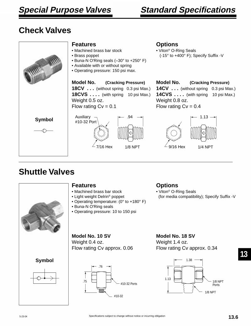
13
Special Purpose Valves
Specifications subject to change without notice or incurring obligation 13.65-23-04
Model No. 10 SVWeight 0.4 oz.Flow rating Cv approx. 0.06
Standard Specifications
Features• Machined brass bar stock• Light weight Delrin® poppet• Operating temperature: (0° to +180° F)• Buna-N O'Ring seals• Operating pressure: 10 to 150 psi
Shuttle Valves
Check Valves
Options• Viton® O-Ring Seals (for media compatibility); Specify Suffix -V
Model No. 18 SVWeight 1.4 oz.Flow rating Cv approx. 0.34
Model No. (Cracking Pressure)18CV . . . (without spring 0.3 psi Max.)18CVS . . . . (with spring 10 psi Max.)Weight 0.5 oz.Flow rating Cv = 0.1
Features• Machined brass bar stock• Brass poppet• Buna-N O'Ring seals (–30° to +250° F)• Available with or without spring• Operating pressure: 150 psi max.
Options• Viton® O-Ring Seals (-15° to +400° F); Specify Suffix -V
Symbol
Symbol 1.13
1/4 NPT9/16 Hex
.94
1/8 NPT7/16 Hex
Auxiliary#10-32 Port
Model No. (Cracking Pressure)14CV . . . (without spring 0.3 psi Max.)14CVS . . . . (with spring 10 psi Max.)Weight 0.8 oz.Flow rating Cv = 0.4
1.38
1/8 NPTPorts
1.13
1/8 NPT
.76
#10-32 Ports.75
#10-32

Specifications subject to change without notice or incurring obligation
14
14.49-9-04
Air Intake / Exhaust Filters
Breather Series MB
OverallLength
HexNPT
Model SM-10A breather / muffler specifically designed to
replace the housing nut on any 53 Style solenoidoperator (except explosion proof, Option -EP) inSection 11 of this catalog. It keeps dirt out andnoise down.
Materials:Body, BrassElement, sintered bronze, 250 micron.
Breather / Muffler for 53 Style Solenoid Exhaust Port
MB Series low profile breather vents havemany applications. They are most often used onsingle acting cylinders or valves to prevent dirtand foreign particles from entering ports open toatmosphere.
Unit should be mounted in a protected positionfree from excessive vibration. Use wrench on hexto tighten the vent.
Materials:Body, BrassElement, Sintered Bronze, 90 micron.
Operating Ranges:Pressure: 300 psi max.Temperature: 35° to 300° F (2° to 149° C)
MB-18 MB-14 MB-38 MB-12
Connection NPT 1/8 1/4 3/8 1/2Overall length In. 1/2 11/16 27/32 31/32Hex In. 7/16 9/16 11/16 7/8
Exhaust Muffler Series MMMM Series mufflers utilize porous sintered
bronze filter elements secured to a brass base.They are used to diffuse air and muffle noise fromthe exhaust ports of air valves, air cylinders and airtools to an acceptable level.
Unit should be mounted in a protected positionfree from excessive vibration. Use wrench on hexto tighten the muffler.
Materials:Body, BrassElement, Sintered Bronze, 40 micron.
Operating Ranges:Pressure: 300 psi max.Temperature: 35° to 300° F (2° to 149° C)
MM-18 MM-14 MM-38 MM-12
Connection NPT 1/8 1/4 3/8 1/2Overall length In. 29/32 1-5/16 1-9/16 1-7/8Hex In. 7/16 9/16 11/16 7/8
Overall Length
HexNPT
.44
9/16Hex
3/8-24
Adds 0.25 to height of solenoid

Vacuum Generator
Specifications subject to change without notice or incurring obligation
15
15.1 3-15-04
VTR-1
Features & Benefits• Low Cost
Simple design results in low cost.No moving parts to wear means no maintenance costs.No maintenance means no down time costs.
• AdjustableControl vacuum level by adjusting air supply pressure.
• CompactAllows you to locate the vacuum generator at the pointof application for highest efficiency.
• QuietNo vanes, pistons or motors.
• SafeNo moving parts, safe in hazardous atmospheres.
• EfficientAir consumption: 4.8 SCFM @ 80 psi inlet.Vacuum level: 28 in. Hg @ 80 psi inlet.
Standard Specifications
Glossary of Terms• Air Consumption
The volume of compressed air, per unit time, requiredto operate the vacuum generator; measured in standardcubic per minute (SCFM).
• Air Supply PressurePressure of the compressed air at the supply inlet of thevacuum generator; measured in pounds per squareinch (psi).
• Time of EvacuationThe time required to evacuate a given system fromatmospheric pressure to a specified negative pressure(vacuum level).
• VacuumVacuum exists when atmospheric air is removed from asystem, resulting in less pressure within the systemthan the atmospheric pressure outside the system.
• Vacuum FlowThe rate at which atmospheric air moves out of asystem is defined as the vacuum flow rate and isexpressed in standard cubic feet per minute (SCFM).
• Vacuum LevelThe level of negative pressure is defined as vacuumlevel and expressed in inches of Mercury (in. Hg.).
Model VTR-1Materials: Aluminum, black anodized
and Brass
Weight: 2.1 oz.
0
2
4
6
8
10
12
14
16
18
20
22
24
26
28
10 20 30 40 50 60 70 80
Vacuum Level
in. Hg
Air Supply Pressure, psig
1
1.5
2
2.5
3
3.5
4
4.5
5
10 20 30 40 50 60 70 80
Air Consumption
SCFM
Air Supply Pressure, psig
0
2
4
6
8
10
12
14
16
18
20
22
24
26
28
0 28.4 44.6 87.8
Time of Evacuationfor 1 Cu. Ft.
in. Hg
Time, Seconds
80 psi Air Supply Pressure
The VTR Vacuum Generator produces highquality vacuum, from shop air, that can beused for applications such as suction cups forparts handling, chamber evacuation, andcountless others.3.33
3/4 Hex
1.06
1/4 NPTExhaust Outlet
1/8 NPTAir Supply Inlet
1/8 NPTVacuum Inlet
![Pneumatic Linear Slides - Fabco-Air › pdf › linear_slides.pdf · Pneumatic Linear Slides Prices Effective September 1, 20117YPJLZ L HLJ[P]L ... 3-Position, tandem cylinder models](https://static.fdocuments.us/doc/165x107/5f03c1be7e708231d40a9e0f/pneumatic-linear-slides-fabco-air-a-pdf-a-linear-pneumatic-linear-slides.jpg)