f2620_standar Practce for Heat Fusion Joining of Polyethylene Pipe
21
Designation: F2620 – 11 ´1 An American National Standard Standard Practice for Heat Fusion Joining of Polyethylene Pipe and Fittings 1 This standard is issued under the fixed designation F2620; the number immediately following the designation indicates the year of original adoption or, in the case of revision, the year of last revision. A number in parentheses indicates the year of last reapproval. A superscript epsilon (´) indicates an editorial change since the last revision or reapproval. ´ 1 NOTE—The title of Table 3 was editorially corrected in December 2011. 1. Scope 1.1 This practice describes procedures for making joints with polyethylene (PE) pipe and fittings by means of heat fusion joining in, but not limited to, a field environment. Other suitable heat fusion joining procedures are available from various sources including pipe and fitting manufacturers. This standard does not purport to address all possible heat fusion joining procedures, or to preclude the use of qualified proce- dures developed by other parties that have been proved to produce reliable heat fusion joints. 1.2 The parameters and procedures are applicable only to joining polyethylene pipe and fittings of related polymer chemistry. They are intended for PE fuel gas pipe per Speci- fication D2513 and PE potable water, sewer and industrial pipe manufactured per Specification F714, Specification D3035, and AWWA C901 and C906. Consult with the pipe manufac- turers to make sure they approve this procedure for the pipe to be joined (see Appendix X1). NOTE 1—Information about polyethylene pipe and fittings that have related polymer chemistry is presented in Plastics Pipe Institute (PPI) TR-33 and TR-41. 1.3 Parts that are within the dimensional tolerances given in present ASTM specifications are required to produce sound joints between polyethylene pipe and fittings when using the joining techniques described in this practice. 1.4 The values stated in inch-pound units are to be regarded as the standard. The values given in parentheses are for information only. 1.5 The text of this practice references notes, footnotes, and appendixes which provide explanatory material. These notes and footnotes (excluding those in tables and figures) shall not be considered as requirements of the practice. 1.6 This standard does not purport to address all of the safety concerns, if any, associated with its use. It is the responsibility of the user of this standard to establish appro- priate safety and health practices and determine the applica- bility of regulatory limitations prior to use. 2. Referenced Documents 2.1 ASTM Standards: 2 D2513 Specification for Polyethylene (PE) Gas Pressure Pipe, Tubing, and Fittings D3035 Specification for Polyethylene (PE) Plastic Pipe (DR-PR) Based on Controlled Outside Diameter F714 Specification for Polyethylene (PE) Plastic Pipe (SDR-PR) Based on Outside Diameter F1056 Specification for Socket Fusion Tools for Use in Socket Fusion Joining Polyethylene Pipe or Tubing and Fittings 2.2 PPI Documents: TR-33 Generic Butt Fusion Joining Procedure for Field Joining of Polyethylene 3 TR-41 Generic Saddle Fusion Joining Procedure for Poly- ethylene Gas Piping 3 2.3 AWWA Documents: AWWA C901 Standard for Polyethylene (PE) Pressure Pipe and Tubing, 1 /2 in. (13 mm) through 3 in. (76 mm), for Water Service 4 AWWA C906 Standard for Polyethylene (PE) Pressure Pipe and Fittings, 4 in. (100 mm) through 63 in. (1575 mm), for Water Distribution and Transmission 4 3. Summary of Practice 3.1 The principle of heat fusion joining of polyethylene (PE) pipe is to heat two prepared surfaces to a designated temperature, then fuse them together by application of a sufficient force. This force causes the melted materials to flow and mix, thereby resulting in fusion. 3.2 The heat-fusion procedures covered in this practice are socket fusion, butt fusion, and saddle fusion. 3.2.1 Procedure 1, Socket Fusion—The socket-fusion pro- cedure involves simultaneously heating the outside surface of 1 This practice is under the jurisdiction of ASTM Committee F17 on Plastic Piping Systems and is the direct responsibility of Subcommittee F17.20 on Joining. Current edition approved Nov. 1, 2011. Published November 2011. Originally approved in 2006. Last previous edition approved in 2009 as F2620–09 ´1 . DOI: 10.1520/F2620-11. 2 For referenced ASTM standards, visit the ASTM website, www.astm.org, or contact ASTM Customer Service at [email protected]. For Annual Book of ASTM Standards volume information, refer to the standard’s Document Summary page on the ASTM website. 3 Available from Plastics Pipe Institute (PPI), 105 Decker Court, Suite 825, Irving, TX 75062, http://www.plasticpipe.org. 4 Available fromAmerican Water WorksAssociation (AWWA), 6666 W. Quincy Ave., Denver, CO 80235, http://www.awwa.org. 1 Copyright © ASTM International, 100 Barr Harbor Drive, PO Box C700, West Conshohocken, PA 19428-2959, United States. Copyright by ASTM Int'l (all rights reserved); Sun Feb 26 11:07:05 EST 2012 Downloaded/printed by Cassia Garro (Haug) pursuant to License Agreement. No further reproductions authorized.
-
Upload
deyvi-vasquez-pittman -
Category
Documents
-
view
13 -
download
2
description
Standar para fusiones con tuberias HDPE
Transcript of f2620_standar Practce for Heat Fusion Joining of Polyethylene Pipe
Designation: F2620 – 11´1 An American National Standard
Standard Practice forHeat Fusion Joining of Polyethylene Pipe and Fittings1
This standard is issued under the fixed designation F2620; the number immediately following the designation indicates the year oforiginal adoption or, in the case of revision, the year of last revision. A number in parentheses indicates the year of last reapproval. Asuperscript epsilon (´) indicates an editorial change since the last revision or reapproval.
´1 NOTE—The title of Table 3 was editorially corrected in December 2011.
1. Scope
1.1 This practice describes procedures for making jointswith polyethylene (PE) pipe and fittings by means of heatfusion joining in, but not limited to, a field environment. Othersuitable heat fusion joining procedures are available fromvarious sources including pipe and fitting manufacturers. Thisstandard does not purport to address all possible heat fusionjoining procedures, or to preclude the use of qualified proce-dures developed by other parties that have been proved toproduce reliable heat fusion joints.
1.2 The parameters and procedures are applicable only tojoining polyethylene pipe and fittings of related polymerchemistry. They are intended for PE fuel gas pipe per Speci-fication D2513 and PE potable water, sewer and industrial pipemanufactured per Specification F714, Specification D3035,and AWWA C901 and C906. Consult with the pipe manufac-turers to make sure they approve this procedure for the pipe tobe joined (see Appendix X1).
NOTE 1—Information about polyethylene pipe and fittings that haverelated polymer chemistry is presented in Plastics Pipe Institute (PPI)TR-33 and TR-41.
1.3 Parts that are within the dimensional tolerances given inpresent ASTM specifications are required to produce soundjoints between polyethylene pipe and fittings when using thejoining techniques described in this practice.
1.4 The values stated in inch-pound units are to be regardedas the standard. The values given in parentheses are forinformation only.
1.5 The text of this practice references notes, footnotes, andappendixes which provide explanatory material. These notesand footnotes (excluding those in tables and figures) shall notbe considered as requirements of the practice.
1.6 This standard does not purport to address all of thesafety concerns, if any, associated with its use. It is theresponsibility of the user of this standard to establish appro-priate safety and health practices and determine the applica-bility of regulatory limitations prior to use.
2. Referenced Documents
2.1 ASTM Standards:2
D2513 Specification for Polyethylene (PE) Gas PressurePipe, Tubing, and Fittings
D3035 Specification for Polyethylene (PE) Plastic Pipe(DR-PR) Based on Controlled Outside Diameter
F714 Specification for Polyethylene (PE) Plastic Pipe(SDR-PR) Based on Outside Diameter
F1056 Specification for Socket Fusion Tools for Use inSocket Fusion Joining Polyethylene Pipe or Tubing andFittings
2.2 PPI Documents:TR-33 Generic Butt Fusion Joining Procedure for Field
Joining of Polyethylene3
TR-41 Generic Saddle Fusion Joining Procedure for Poly-ethylene Gas Piping3
2.3 AWWA Documents:AWWA C901 Standard for Polyethylene (PE) Pressure Pipe
and Tubing, 1⁄2 in. (13 mm) through 3 in. (76 mm), forWater Service4
AWWA C906 Standard for Polyethylene (PE) Pressure Pipeand Fittings, 4 in. (100 mm) through 63 in. (1575 mm), forWater Distribution and Transmission4
3. Summary of Practice
3.1 The principle of heat fusion joining of polyethylene(PE) pipe is to heat two prepared surfaces to a designatedtemperature, then fuse them together by application of asufficient force. This force causes the melted materials to flowand mix, thereby resulting in fusion.
3.2 The heat-fusion procedures covered in this practice aresocket fusion, butt fusion, and saddle fusion.
3.2.1 Procedure 1, Socket Fusion—The socket-fusion pro-cedure involves simultaneously heating the outside surface of
1 This practice is under the jurisdiction of ASTM Committee F17 on PlasticPiping Systems and is the direct responsibility of Subcommittee F17.20 on Joining.
Current edition approved Nov. 1, 2011. Published November 2011. Originallyapproved in 2006. Last previous edition approved in 2009 as F2620–09´1 . DOI:10.1520/F2620-11.
2 For referenced ASTM standards, visit the ASTM website, www.astm.org, orcontact ASTM Customer Service at [email protected]. For Annual Book of ASTMStandards volume information, refer to the standard’s Document Summary page onthe ASTM website.
3 Available from Plastics Pipe Institute (PPI), 105 Decker Court, Suite 825,Irving, TX 75062, http://www.plasticpipe.org.
4 Available from American Water Works Association (AWWA), 6666 W. QuincyAve., Denver, CO 80235, http://www.awwa.org.
1
Copyright © ASTM International, 100 Barr Harbor Drive, PO Box C700, West Conshohocken, PA 19428-2959, United States.
Copyright by ASTM Int'l (all rights reserved); Sun Feb 26 11:07:05 EST 2012Downloaded/printed byCassia Garro (Haug) pursuant to License Agreement. No further reproductions authorized.

a pipe end and the inside of a fitting socket, which is sized tobe smaller than the smallest outside diameter of the pipe. Afterthe proper melt has been generated at each face to be mated,the two components are joined by inserting one component intothe other. See Fig. 1. The fusion bond is formed at the interfaceresulting from the interference fit. The melts from the twocomponents flow together and fuse as the joint cools. Optionalalignment devices are used to hold the pipe and socket fittingin longitudinal alignment during the joining process; especiallywith pipe sizes IPS 3 in. (89 mm) and larger. Automated socketfusion is not addressed in this procedure.
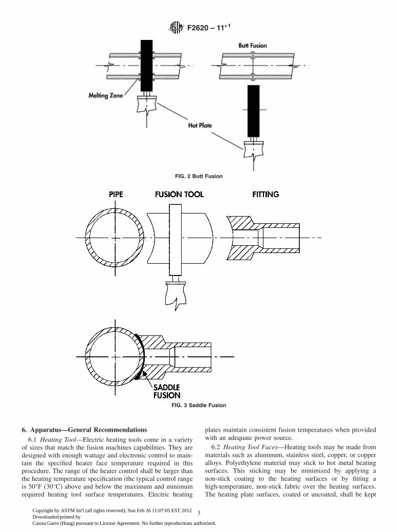
3.2.2 Procedure 2, Butt Fusion—The butt-fusion procedurein its simplest form consists of heating the squared ends of twopipes, a pipe and a fitting, or two fittings, by holding themagainst a heated plate, removing the heater plate when theproper melt is obtained, promptly bringing the ends together,and allowing the joint to cool while maintaining the appropri-ate applied force.
3.2.2.1 An appropriately sized butt fusion machine is usedto clamp, align and face the pipe or fitting ends and to apply thespecified fusion force. See Fig. 2.
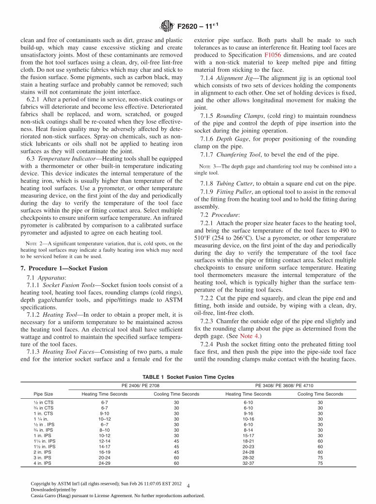
3.2.3 Procedure 3, Saddle Fusion—The saddle-fusion pro-cedure involves melting the concave surface of the base of asaddle fitting, while simultaneously melting a matching patternon the surface of the pipe, bringing the two melted surfacestogether and allowing the joint to cool while maintaining theappropriate applied force. See Fig. 3.
3.2.3.1 An appropriately sized saddle fusion machine isused to clamp the pipe main and the fitting, align the parts andapply the specified fusion force.
4. Significance and Use
4.1 The procedures described in Sections 7-9 are primarilyintended for (but not limited to) field joining of polyethylene
(PE) pipe and fittings, using suitable equipment and appropri-ate environmental control procedures. When properly imple-mented, strong pressure/leak-tight joints are produced. Whenthese joints are destructively tested, the failure occurs outsidethe fusion joined area.
4.2 Melt characteristics, average molecular weight and mo-lecular weight distribution are influential factors in establishingsuitable fusion parameters; therefore, consider the manufactur-er’s instructions in the use or development of a specific fusionprocedure. See Annex A1.
4.3 The socket fusion, butt fusion, and saddle fusion proce-dures in this practice are suitable for joining PE gas pipe andfittings, PE water pipe and fittings, and PE general purposepipes and fittings made to PE product specifications fromorganizations such as ASTM, AWWA, API, and ISO that areused in pressure, low pressure and non-pressure applications.For gas applications, qualification of the procedure by testingjoints made using the procedure in accordance with regulationsfrom the authority having jurisdiction are required.
5. Operator Experience
5.1 Skill and knowledge on the part of the operator arerequired to obtain a good quality joint. This skill and knowl-edge is obtained by making joints in accordance with provenprocedures under the guidance of skilled operators. Evaluateoperator proficiency by testing sample joints.
5.2 The party responsible for the joining of polyethylenepipe and fittings shall ensure that detailed procedures devel-oped in conjunction with applicable codes and regulations andthe manufacturers of the pipe, fittings, and joining equipmentinvolved, including the safety precautions to be followed, areissued before actual joining operations begin.
FIG. 1 Socket Fusion
F2620 – 11´1
2
Copyright by ASTM Int'l (all rights reserved); Sun Feb 26 11:07:05 EST 2012Downloaded/printed byCassia Garro (Haug) pursuant to License Agreement. No further reproductions authorized.
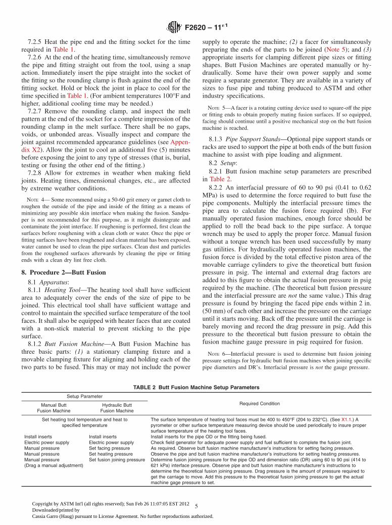
6. Apparatus—General Recommendations
6.1 Heating Tool—Electric heating tools come in a varietyof sizes that match the fusion machines capabilities. They aredesigned with enough wattage and electronic control to main-tain the specified heater face temperature required in thisprocedure. The range of the heater control shall be larger thanthe heating temperature specification (the typical control rangeis 50°F (30°C) above and below the maximum and minimumrequired heating tool surface temperatures. Electric heating
plates maintain consistent fusion temperatures when providedwith an adequate power source.
6.2 Heating Tool Faces—Heating tools may be made frommaterials such as aluminum, stainless steel, copper, or copperalloys. Polyethylene material may stick to hot metal heatingsurfaces. This sticking may be minimized by applying anon-stick coating to the heating surfaces or by fitting ahigh-temperature, non-stick fabric over the heating surfaces.The heating plate surfaces, coated or uncoated, shall be kept
FIG. 2 Butt Fusion
FIG. 3 Saddle Fusion
F2620 – 11´1
3
Copyright by ASTM Int'l (all rights reserved); Sun Feb 26 11:07:05 EST 2012Downloaded/printed byCassia Garro (Haug) pursuant to License Agreement. No further reproductions authorized.
clean and free of contaminants such as dirt, grease and plasticbuild-up, which may cause excessive sticking and createunsatisfactory joints. Most of these contaminants are removedfrom the hot tool surfaces using a clean, dry, oil-free lint-freecloth. Do not use synthetic fabrics which may char and stick tothe fusion surface. Some pigments, such as carbon black, maystain a heating surface and probably cannot be removed; suchstains will not contaminate the joint interface.
6.2.1 After a period of time in service, non-stick coatings orfabrics will deteriorate and become less effective. Deterioratedfabrics shall be replaced, and worn, scratched, or gougednon-stick coatings shall be re-coated when they lose effective-ness. Heat fusion quality may be adversely affected by dete-riorated non-stick surfaces. Spray-on chemicals, such as non-stick lubricants or oils shall not be applied to heating ironsurfaces as they will contaminate the joint.
6.3 Temperature Indicator—Heating tools shall be equippedwith a thermometer or other built-in temperature indicatingdevice. This device indicates the internal temperature of theheating iron, which is usually higher than temperature of theheating tool surfaces. Use a pyrometer, or other temperaturemeasuring device, on the first joint of the day and periodicallyduring the day to verify the temperature of the tool facesurfaces within the pipe or fitting contact area. Select multiplecheckpoints to ensure uniform surface temperature. An infraredpyrometer is calibrated by comparison to a calibrated surfacepyrometer and adjusted to agree on each heating tool.
NOTE 2—A significant temperature variation, that is, cold spots, on theheating tool surfaces may indicate a faulty heating iron which may needto be serviced before it can be used.
7. Procedure 1—Socket Fusion
7.1 Apparatus:7.1.1 Socket Fusion Tools—Socket fusion tools consist of a
heating tool, heating tool faces, rounding clamps (cold rings),depth gage/chamfer tools, and pipe/fittings made to ASTMspecifications.
7.1.2 Heating Tool—In order to obtain a proper melt, it isnecessary for a uniform temperature to be maintained acrossthe heating tool faces. An electrical tool shall have sufficientwattage and control to maintain the specified surface tempera-ture of the tool faces.
7.1.3 Heating Tool Faces—Consisting of two parts, a maleend for the interior socket surface and a female end for the
exterior pipe surface. Both parts shall be made to suchtolerances as to cause an interference fit. Heating tool faces areproduced to Specification F1056 dimensions, and are coatedwith a non-stick material to keep melted pipe and fittingmaterial from sticking to the face.
7.1.4 Alignment Jig—The alignment jig is an optional toolwhich consists of two sets of devices holding the componentsin alignment to each other. One set of holding devices is fixed,and the other allows longitudinal movement for making thejoint.
7.1.5 Rounding Clamps, (cold ring) to maintain roundnessof the pipe and control the depth of pipe insertion into thesocket during the joining operation.
7.1.6 Depth Gage, for proper positioning of the roundingclamp on the pipe.
7.1.7 Chamfering Tool, to bevel the end of the pipe.
NOTE 3—The depth gage and chamfering tool may be combined into asingle tool.
7.1.8 Tubing Cutter, to obtain a square end cut on the pipe.7.1.9 Fitting Puller, an optional tool to assist in the removal
of the fitting from the heating tool and to hold the fitting duringassembly.
7.2 Procedure:7.2.1 Attach the proper size heater faces to the heating tool,
and bring the surface temperature of the tool faces to 490 to510°F (254 to 266°C). Use a pyrometer, or other temperaturemeasuring device, on the first joint of the day and periodicallyduring the day to verify the temperature of the tool facesurfaces within the pipe or fitting contact area. Select multiplecheckpoints to ensure uniform surface temperature. Heatingtool thermometers measure the internal temperature of theheating tool, which is typically higher than the surface tem-perature of the heating tool faces.
7.2.2 Cut the pipe end squarely, and clean the pipe end andfitting, both inside and outside, by wiping with a clean, dry,oil-free, lint-free cloth.
7.2.3 Chamfer the outside edge of the pipe end slightly andfix the rounding clamp about the pipe as determined from thedepth gage. (See Note 4.)
7.2.4 Push the socket fitting onto the preheated fitting toolface first, and then push the pipe into the pipe-side tool faceuntil the rounding clamps make contact with the heating faces.
TABLE 1 Socket Fusion Time Cycles
PE 2406/ PE 2708 PE 3408/ PE 3608/ PE 4710
Pipe Size Heating Time Seconds Cooling Time Seconds Heating Time Seconds Cooling Time Seconds
1⁄2 in CTS 6-7 30 6-10 303⁄4 in CTS 6-7 30 6-10 301 in. CTS 9-10 30 9-16 301 1⁄4 in. 10–12 30 10-16 301⁄2 in . IPS 6–7 30 6-10 303⁄4 in. IPS 8–10 30 8-14 301 in. IPS 10-12 30 15-17 3011⁄4 in. IPS 12-14 45 18-21 6011⁄2 in. IPS 14-17 45 20-23 602 in. IPS 16-19 45 24-28 603 in. IPS 20-24 60 28-32 754 in. IPS 24-29 60 32-37 75
F2620 – 11´1
4
Copyright by ASTM Int'l (all rights reserved); Sun Feb 26 11:07:05 EST 2012Downloaded/printed byCassia Garro (Haug) pursuant to License Agreement. No further reproductions authorized.
7.2.5 Heat the pipe end and the fitting socket for the timerequired in Table 1.
7.2.6 At the end of the heating time, simultaneously removethe pipe and fitting straight out from the tool, using a snapaction. Immediately insert the pipe straight into the socket ofthe fitting so the rounding clamp is flush against the end of thefitting socket. Hold or block the joint in place to cool for thetime specified in Table 1. (For ambient temperatures 100°F andhigher, additional cooling time may be needed.)
7.2.7 Remove the rounding clamp, and inspect the meltpattern at the end of the socket for a complete impression of therounding clamp in the melt surface. There shall be no gaps,voids, or unbonded areas. Visually inspect and compare thejoint against recommended appearance guidelines (see Appen-dix X2). Allow the joint to cool an additional five (5) minutesbefore exposing the joint to any type of stresses (that is, burial,testing or fusing the other end of the fitting.)
7.2.8 Allow for extremes in weather when making fieldjoints. Heating times, dimensional changes, etc., are affectedby extreme weather conditions.
NOTE 4— Some recommend using a 50-60 grit emery or garnet cloth toroughen the outside of the pipe and inside of the fitting as a means ofminimizing any possible skin interface when making the fusion. Sandpa-per is not recommended for this purpose, as it might disintegrate andcontaminate the joint interface. If roughening is performed, first clean thesurfaces before roughening with a clean cloth or water. Once the pipe orfitting surfaces have been roughened and clean material has been exposed,water cannot be used to clean the pipe surfaces. Clean dust and particlesfrom the roughened surfaces afterwards by cleaning the pipe or fittingends with a clean dry lint free cloth.
8. Procedure 2—Butt Fusion
8.1 Apparatus:8.1.1 Heating Tool—The heating tool shall have sufficient
area to adequately cover the ends of the size of pipe to bejoined. This electrical tool shall have sufficient wattage andcontrol to maintain the specified surface temperature of the toolfaces. It shall also be equipped with heater faces that are coatedwith a non-stick material to prevent sticking to the pipesurface.
8.1.2 Butt Fusion Machine—A Butt Fusion Machine hasthree basic parts: (1) a stationary clamping fixture and amovable clamping fixture for aligning and holding each of thetwo parts to be fused. This may or may not include the power
supply to operate the machine; (2) a facer for simultaneouslypreparing the ends of the parts to be joined (Note 5); and (3)appropriate inserts for clamping different pipe sizes or fittingshapes. Butt Fusion Machines are operated manually or hy-draulically. Some have their own power supply and somerequire a separate generator. They are available in a variety ofsizes to fuse pipe and tubing produced to ASTM and otherindustry specifications.
NOTE 5—A facer is a rotating cutting device used to square-off the pipeor fitting ends to obtain properly mating fusion surfaces. If so equipped,facing should continue until a positive mechanical stop on the butt fusionmachine is reached.
8.1.3 Pipe Support Stands—Optional pipe support stands orracks are used to support the pipe at both ends of the butt fusionmachine to assist with pipe loading and alignment.
8.2 Setup:8.2.1 Butt fusion machine setup parameters are prescribed
in Table 2.8.2.2 An interfacial pressure of 60 to 90 psi (0.41 to 0.62
MPa) is used to determine the force required to butt fuse thepipe components. Multiply the interfacial pressure times thepipe area to calculate the fusion force required (lb). Formanually operated fusion machines, enough force should beapplied to roll the bead back to the pipe surface. A torquewrench may be used to apply the proper force. Manual fusionwithout a torque wrench has been used successfully by manygas utilities. For hydraulically operated fusion machines, thefusion force is divided by the total effective piston area of themovable carriage cylinders to give the theoretical butt fusionpressure in psig. The internal and external drag factors areadded to this figure to obtain the actual fusion pressure in psigrequired by the machine. (The theoretical butt fusion pressureand the interfacial pressure are not the same value.) This dragpressure is found by bringing the faced pipe ends within 2 in.(50 mm) of each other and increase the pressure on the carriageuntil it starts moving. Back off the pressure until the carriage isbarely moving and record the drag pressure in psig. Add thispressure to the theoretical butt fusion pressure to obtain thefusion machine gauge pressure in psig required for fusion.
NOTE 6—Interfacial pressure is used to determine butt fusion joiningpressure settings for hydraulic butt fusion machines when joining specificpipe diameters and DR’s. Interfacial pressure is not the gauge pressure.
TABLE 2 Butt Fusion Machine Setup Parameters
Setup Parameter
Required ConditionManual ButtFusion Machine
Hydraulic ButtFusion Machine
Set heating tool temperature and heat tospecified temperature
The surface temperature of heating tool faces must be 400 to 450°F (204 to 232°C). (See X1.1.) Apyrometer or other surface temperature measuring device should be used periodically to insure propersurface temperature of the heating tool faces.
Install inserts Install inserts Install inserts for the pipe OD or the fitting being fused.Electric power supply Electric power supply Check field generator for adequate power supply and fuel sufficient to complete the fusion joint.Manual pressure Set facing pressure As required. Observe butt fusion machine manufacturer’s instructions for setting facing pressure.Manual pressure Set heating pressure Observe the pipe and butt fusion machine manufacturer’s instructions for setting heating pressures.Manual pressure(Drag a manual adjustment)
Set fusion joining pressure Determine fusion joining pressure for the pipe OD and dimension ratio (DR) using 60 to 90 psi (414 to621 kPa) interface pressure. Observe pipe and butt fusion machine manufacturer’s instructions todetermine the theoretical fusion joining pressure. Drag pressure is the amount of pressure required toget the carriage to move. Add this pressure to the theoretical fusion joining pressure to get the actualmachine gage pressure to set.
F2620 – 11´1
5
Copyright by ASTM Int'l (all rights reserved); Sun Feb 26 11:07:05 EST 2012Downloaded/printed byCassia Garro (Haug) pursuant to License Agreement. No further reproductions authorized.
8.3 Procedure:8.3.1 Clean the inside and outside of the components (pipe
or pipe and fitting) to be joined with a clean lint-free dry cloth.Remove all foreign matter from the piping component surfaceswhere they will be clamped in the butt fusion machine.
8.3.2 If applicable, place pipe support stands at both ends ofthe butt fusion machine and adjust the support stands to alignthe pipe with the fusion machine centerline. Install the pipes orfittings being joined in the stationary and movable clamps ofthe butt fusion machine. Leave enough pipe protruding throughthe clamps to allow for facing and clamp the pipe or fitting inthe machine.
8.3.2.1 Take care when placing pipe or fittings in the buttfusion machine. Pipes shall be aligned before the alignmentclamp is closed. Do not force the pipe into alignment bypushing it against the side of an open butt fusion machineclamp. Pipes that are freshly cut and molded fittings generallydo not have toe-in, and when mated to old-cut pipe orfabricated fittings, removing toe-in can ease adjustment forhigh-low alignment.
8.3.3 Face the piping component ends until the facer bot-toms out on the stops and is locked between the jaws toestablish clean, parallel mating surfaces between the pipe/fitting ends (see Note 5). Open the jaws, remove the facer andall shavings and debris from the facing operation by brushingaway with a clean, dry, lint-free cloth.
8.3.4 Check the pipe ends for high-low alignment andout-of-roundness. If adjustment is needed, adjust the high sidedown by tightening the high side clamp. Do not loosen the lowside clamp or slippage may occur during fusion. Re-face thepipe or fitting ends if excessive adjustment is required (morethan 180° rotation of the clamp knob) and remove any shavingsfrom the re-facing operation with a clean, lint-free cotton cloth.The maximum OD high-low misalignment allowed in the buttfusion procedure is to be less than 10 % of the pipe minimumwall thickness.
8.3.5 Verify that the heater surface temperatures are in thespecified temperature range 400 to 450°F (204 to 232°C). (SeeAppendix X1.) A pyrometer or other surface temperaturemeasuring device should be used before the first joint of theday and periodically throughout the day to insure propertemperature of the heating tool face. All pyrometers aresensitive to usage techniques. Carefully follow the manufac-turer’s instructions for best results.
8.3.5.1 Place the heating tool in the butt fusion machinebetween the piping component ends and bring the pipe orfitting ends into full contact with the heating tool at fusionpressure. Briefly ensure full contact between piping componentends and the heating tool and then reduce the pressure to dragpressure but without breaking contact between the pipingcomponent ends and the heating tool. (On larger pipe sizes, (14in. and larger) hold fusion pressure until a slight melt isobserved around the circumference of the pipe or fitting beforereducing pressure. This normally varies from about 10 s on 14in. pipe and smaller and could be greater than 2 min on 36 andlarger pipe sizes.)
8.3.5.2 Once the indication of melt is observed around thecircumference of the pipe, begin the heat soak by reducing the
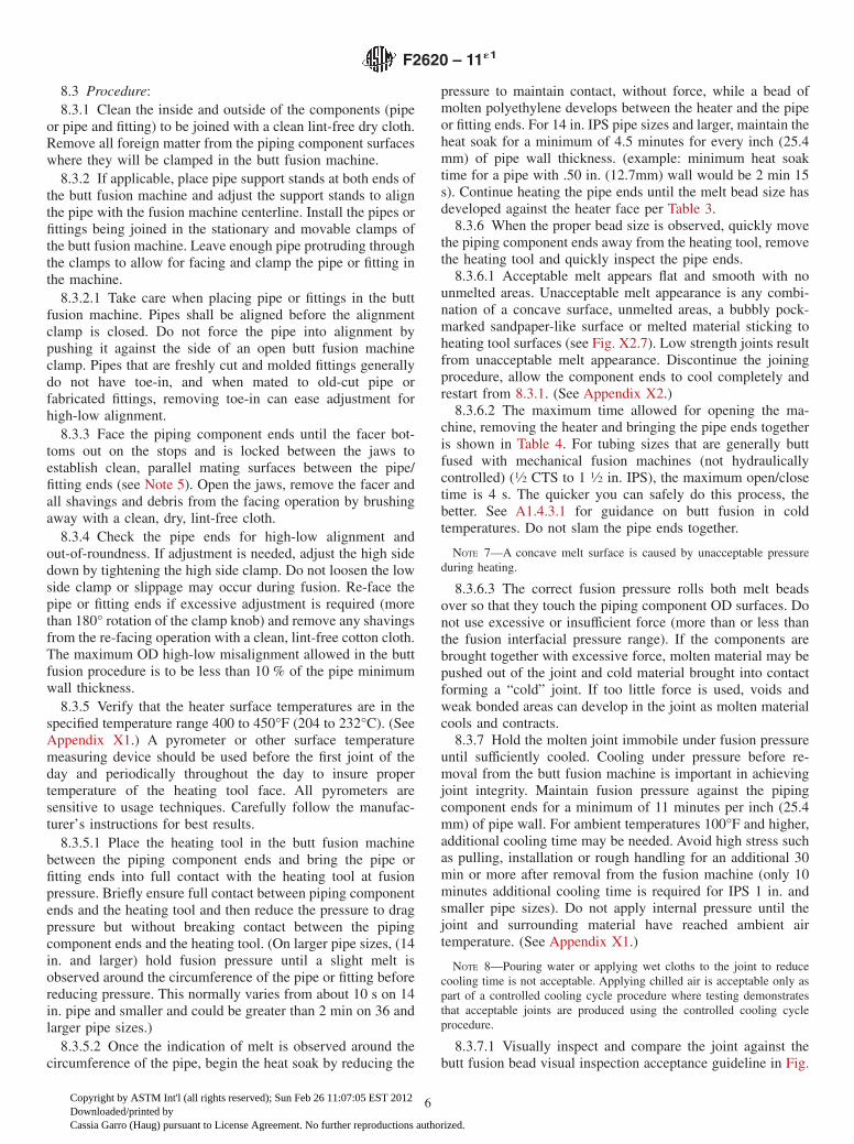
pressure to maintain contact, without force, while a bead ofmolten polyethylene develops between the heater and the pipeor fitting ends. For 14 in. IPS pipe sizes and larger, maintain theheat soak for a minimum of 4.5 minutes for every inch (25.4mm) of pipe wall thickness. (example: minimum heat soaktime for a pipe with .50 in. (12.7mm) wall would be 2 min 15s). Continue heating the pipe ends until the melt bead size hasdeveloped against the heater face per Table 3.
8.3.6 When the proper bead size is observed, quickly movethe piping component ends away from the heating tool, removethe heating tool and quickly inspect the pipe ends.
8.3.6.1 Acceptable melt appears flat and smooth with nounmelted areas. Unacceptable melt appearance is any combi-nation of a concave surface, unmelted areas, a bubbly pock-marked sandpaper-like surface or melted material sticking toheating tool surfaces (see Fig. X2.7). Low strength joints resultfrom unacceptable melt appearance. Discontinue the joiningprocedure, allow the component ends to cool completely andrestart from 8.3.1. (See Appendix X2.)
8.3.6.2 The maximum time allowed for opening the ma-chine, removing the heater and bringing the pipe ends togetheris shown in Table 4. For tubing sizes that are generally buttfused with mechanical fusion machines (not hydraulicallycontrolled) (1⁄2 CTS to 1 1⁄2 in. IPS), the maximum open/closetime is 4 s. The quicker you can safely do this process, thebetter. See A1.4.3.1 for guidance on butt fusion in coldtemperatures. Do not slam the pipe ends together.
NOTE 7—A concave melt surface is caused by unacceptable pressureduring heating.
8.3.6.3 The correct fusion pressure rolls both melt beadsover so that they touch the piping component OD surfaces. Donot use excessive or insufficient force (more than or less thanthe fusion interfacial pressure range). If the components arebrought together with excessive force, molten material may bepushed out of the joint and cold material brought into contactforming a “cold” joint. If too little force is used, voids andweak bonded areas can develop in the joint as molten materialcools and contracts.
8.3.7 Hold the molten joint immobile under fusion pressureuntil sufficiently cooled. Cooling under pressure before re-moval from the butt fusion machine is important in achievingjoint integrity. Maintain fusion pressure against the pipingcomponent ends for a minimum of 11 minutes per inch (25.4mm) of pipe wall. For ambient temperatures 100°F and higher,additional cooling time may be needed. Avoid high stress suchas pulling, installation or rough handling for an additional 30min or more after removal from the fusion machine (only 10minutes additional cooling time is required for IPS 1 in. andsmaller pipe sizes). Do not apply internal pressure until thejoint and surrounding material have reached ambient airtemperature. (See Appendix X1.)
NOTE 8—Pouring water or applying wet cloths to the joint to reducecooling time is not acceptable. Applying chilled air is acceptable only aspart of a controlled cooling cycle procedure where testing demonstratesthat acceptable joints are produced using the controlled cooling cycleprocedure.
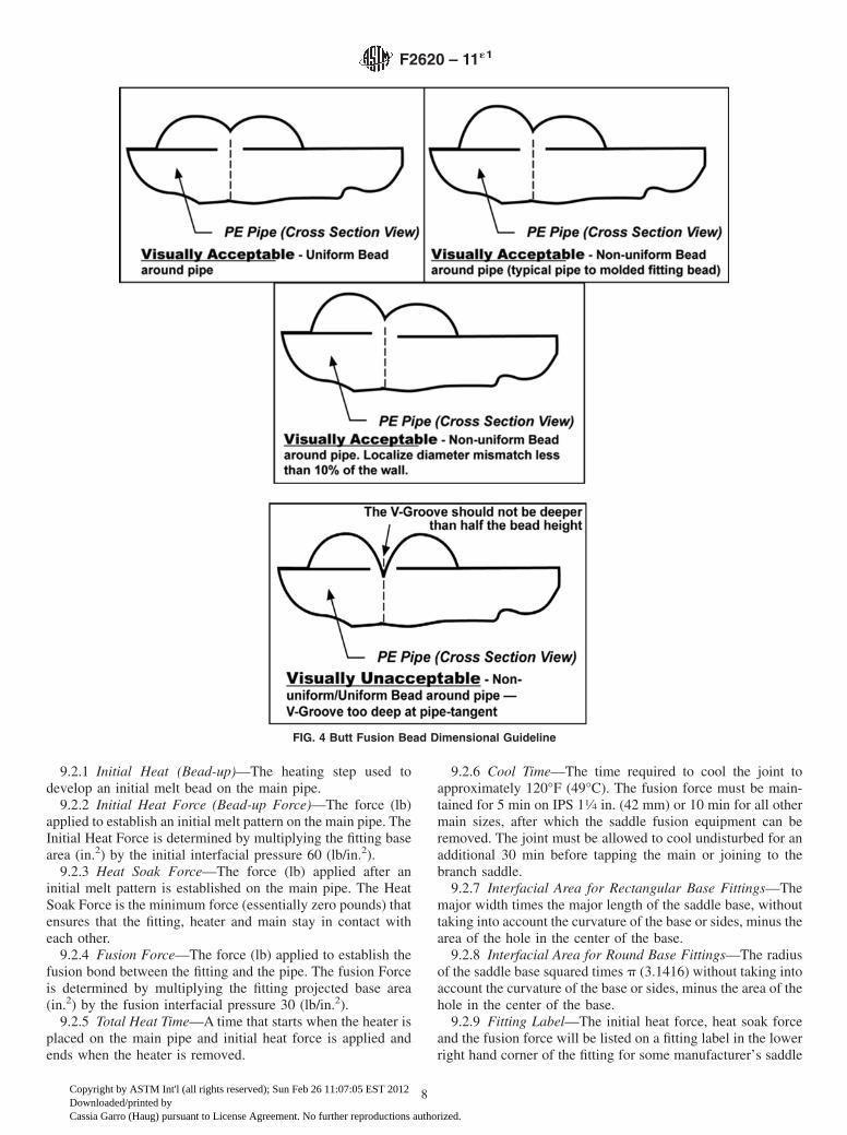
8.3.7.1 Visually inspect and compare the joint against thebutt fusion bead visual inspection acceptance guideline in Fig.
F2620 – 11´1
6
Copyright by ASTM Int'l (all rights reserved); Sun Feb 26 11:07:05 EST 2012Downloaded/printed byCassia Garro (Haug) pursuant to License Agreement. No further reproductions authorized.
4. The v-groove between the beads should not be deeper thanhalf the bead height above the pipe surface. When butt fusingto molded fittings, the fitting-side bead may display shapeirregularities such as minor indentations, deflections and non-uniform bead rollover from molded part cooling and knit lines.In such cases, visual evaluation is based mainly on the size andshape of the pipe-side bead. (See Appendix X2 for additionalguidance.)
9. Procedure 3—Saddle Fusion
9.1 Apparatus:9.1.1 Heating Tool and Faces—This electrical tool shall
have sufficient wattage and control to maintain the specifiedsurface temperature of the tool faces. The serrated or smoothfaces are matched sets, by pipe size, of concave and convex
blocks, which bolt or clamp onto a flat heating tool. Theheating faces are coated with a non-stick material to preventsticking to the pipe or fitting surfaces.
9.1.2 Saddle Fusion Tool—This tool clamps to the main,rounding and supporting the main for good alignment betweenthe pipe and fitting. It holds the fitting, in correct alignment tothe main. It also applies and indicates the proper force duringthe fusion process. A support or bolster is clamped to IPS 6 in.(168 mm) and smaller main pipe opposite the fitting installa-tion area to support the main and assist in rounding the pipe.
9.1.3 Optional Flexible Heat Shield—A flexible heat resis-tant metal or insulated fabric pad used to help establish a meltpattern on larger mains before applying heat to the fitting.
9.2 Saddle Fusion Terminology:
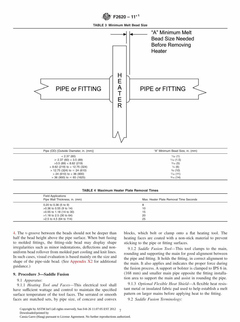
TABLE 3 Minimum Melt Bead Size
Pipe (OD) [Outside Diameter, in. (mm)] “A” Minimum Bead Size, in. (mm)
< 2.37 (60) 1⁄32 (1)$ 2.37 (60) < 3.5 (89) 1⁄16 (1.5)>3.5 (89) < 8.62 (219) 3⁄16 (5)
> 8.62 (219) to < 12.75 (324) 1⁄4 (6)> 12.75 (324) to # 24 (610) 3⁄8 (10)
> 24 (610) to < 36 (900) 7⁄16 (11)> 36 (900) to # 65 (1625) 9⁄16 (14)
TABLE 4 Maximum Heater Plate Removal Times
Field ApplicationsPipe Wall Thickness, in. (mm) Max. Heater Plate Removal Time Seconds
0.20 to 0.36 (5 to 9) 8>0.36 to 0.55 (9 to 14) 10>0.55 to 1.18 (14 to 30) 15>1.18 to 2.5 (30 to 64) 20>2.5 to 4.5 (64 to 114) 25
F2620 – 11´1
7
Copyright by ASTM Int'l (all rights reserved); Sun Feb 26 11:07:05 EST 2012Downloaded/printed byCassia Garro (Haug) pursuant to License Agreement. No further reproductions authorized.
9.2.1 Initial Heat (Bead-up)—The heating step used todevelop an initial melt bead on the main pipe.
9.2.2 Initial Heat Force (Bead-up Force)—The force (lb)applied to establish an initial melt pattern on the main pipe. TheInitial Heat Force is determined by multiplying the fitting basearea (in.2) by the initial interfacial pressure 60 (lb/in.2).
9.2.3 Heat Soak Force—The force (lb) applied after aninitial melt pattern is established on the main pipe. The HeatSoak Force is the minimum force (essentially zero pounds) thatensures that the fitting, heater and main stay in contact witheach other.
9.2.4 Fusion Force—The force (lb) applied to establish thefusion bond between the fitting and the pipe. The fusion Forceis determined by multiplying the fitting projected base area(in.2) by the fusion interfacial pressure 30 (lb/in.2).
9.2.5 Total Heat Time—A time that starts when the heater isplaced on the main pipe and initial heat force is applied andends when the heater is removed.
9.2.6 Cool Time—The time required to cool the joint toapproximately 120°F (49°C). The fusion force must be main-tained for 5 min on IPS 11⁄4 in. (42 mm) or 10 min for all othermain sizes, after which the saddle fusion equipment can beremoved. The joint must be allowed to cool undisturbed for anadditional 30 min before tapping the main or joining to thebranch saddle.
9.2.7 Interfacial Area for Rectangular Base Fittings—Themajor width times the major length of the saddle base, withouttaking into account the curvature of the base or sides, minus thearea of the hole in the center of the base.
9.2.8 Interfacial Area for Round Base Fittings—The radiusof the saddle base squared times p (3.1416) without taking intoaccount the curvature of the base or sides, minus the area of thehole in the center of the base.
9.2.9 Fitting Label—The initial heat force, heat soak forceand the fusion force will be listed on a fitting label in the lowerright hand corner of the fitting for some manufacturer’s saddle
FIG. 4 Butt Fusion Bead Dimensional Guideline
F2620 – 11´1
8
Copyright by ASTM Int'l (all rights reserved); Sun Feb 26 11:07:05 EST 2012Downloaded/printed byCassia Garro (Haug) pursuant to License Agreement. No further reproductions authorized.
fusion fittings. This will eliminate the need to calculate thefusion forces in the field (for example, 180/0/90). The label isnot mandatory, therefore the heat and fusion forces need to becalculated if the label is not present.
9.3 Setup:9.3.1 Select and install the proper heating tool faces to the
heating tool based on the main size and fitting base size.Consult the pipe, fitting or equipment manufacturer’s recom-mendations.
9.3.2 Plug in the heating tool and bring the heating tool facesurfaces to 490 to 510°F (254 to 266°C) (see Table 5). Apyrometer or other surface temperature measuring device isused to determine and periodically check the heating toolsurface temperature. Heating tool thermometers measure theinternal temperature of the heating tool which is typicallyhigher than the surface temperature of the heating tool faces.
9.3.3 Install the proper clamps in the Saddle Fusion Tool forthe main size to be fused. Install the proper fitting clamp for thefitting to be joined. Consult the pipe, fitting or equipmentmanufacturer’s recommendations.
9.4 Procedure:9.4.1 Preparation:9.4.1.1 Install the Saddle Fusion Tool on the main according
to the manufacturer’s instructions. The tool should be centeredover a clean, dry location where the fitting will be fused.Secure the tool to the main. A main bolster or support isrecommended under the pipe on IPS 6 in. (168 mm) andsmaller main pipe sizes.
9.4.1.2 Abrade or scrape the surface of the main, where thefitting will be joined, approximately 0.007 in. (.178mm) deepto remove any oxidation or contamination. This can be donebefore or after the Tool is attached to the main. The abraded/scraped area must be larger than the area covered by the fittingbase. It is important that the pipe surface be free from any typeof contaminates that may be spread before the scraping orabrading process begins. Marks can be made on the outersurface of the pipe to aid in visual indication of abrading/scraping coverage, however the marks should be made with anon-petroleum based fast drying marker. After abrading/scraping, clean the pipe or fitting ends with a clean dry lint freecloth. All markings on the pipe surface should be removedbefore beginning the heat cycle.
9.4.1.3 If the fitting is not protected in a clean plastic bag,abrade the fusion surface of the fitting with 50 to 60 grit utilitycloth; remove all dust and residue with a clean dry lint free
cloth. Insert the fitting in the Saddle Fusion Tool loosely. Usingthe Saddle Fusion Tool, move the fitting base against the mainpipe and apply about 100 lbf to seat the fitting. Secure thefitting in the Saddle Fusion Tool.
9.4.2 Heating Procedure for Small Fittings (<2 in. IPS) (seeTable 5):
9.4.2.1 Place the heating tool on the main centered beneaththe fitting base. Immediately move the fitting against the heaterfaces, apply the Initial Heat Force (see fitting label), and startthe heat time. Apply the Initial Heat Force until melt is firstobserved on the crown of the pipe main (Initial Heat is the termused to describe the initial heating (bead-up) step to develop amelt bead on the main pipe and usually is 3 to 5 s) and thenreduce the force to the Heat Soak Force (Bead-up force) (seefitting label). Maintain the Heat Soak Force until the Total HeatTime is complete. Total Heat Time ends:
(1) When the Total Heating Time expires for a pressurizedIPS 11⁄4 in. (42 mm) or IPS 2 in. (63 mm) main, or
(2) When a melt bead of about 1⁄16 in. (2 mm) is visible allaround the fitting base for a IPS 11⁄4 in. (42 mm) or IPS 2 in.(63 mm) non-pressurized main, or a larger pressurized ornon-pressurized main, (see Table 5).
9.4.2.2 At the end of the Total Heat Time, remove the fittingfrom the heater and the heater from the main with a quicksnapping action. Quickly check for a complete and even meltpattern on the pipe main and fitting heated surfaces (nounheated areas).
9.4.3 Heating Procedure for Large Fittings (>IPS 3 in.) andLarge Mains (>IPS 6 in.) (see Table 5):
9.4.3.1 Place the heating tool on the main centered beneaththe fitting base, and then place the Flexible Heat Shieldbetween the heating tool and the fitting base. (This step usuallyrequires an assistant to handle the Flexible Heat Shield).
9.4.3.2 Move the fitting against the Flexible Heat Shield,apply Initial Heat Force, and observe melt bead formation onthe main all around the heating tool faces. When a melt bead isfirst visible on the main all around the heating tool faces, in aquick continuous motion, release the Initial Heat Force, raisethe fitting slightly, remove the Flexible Heat Shield, move thefitting against the heating tool face, apply Initial Heat Forceand start the heat time. When a melt bead is first visible allaround the fitting base (usually about 3 to 5 s) immediatelyreduce applied force to the Heat Soak Force (usually zero).Maintain the Heat Soak Force until the Table 5 Total Heat Timeends.
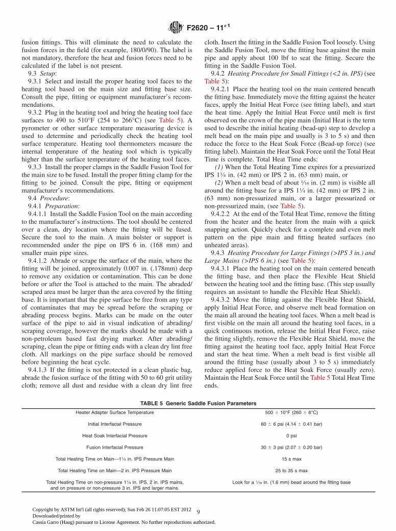
TABLE 5 Generic Saddle Fusion Parameters
Heater Adapter Surface Temperature 500 6 10°F (260 6 6°C)
Initial Interfacial Pressure 60 6 6 psi (4.14 6 0.41 bar)
Heat Soak Interfacial Pressure 0 psi
Fusion Interfacial Pressure 30 6 3 psi (2.07 6 0.20 bar)
Total Heating Time on Main—11⁄4 in. IPS Pressure Main 15 s max
Total Heating Time on Main—2 in. IPS Pressure Main 25 to 35 s max
Total Heating Time on non-pressure 11⁄4 in. IPS, 2 in. IPS mains,and on pressure or non-pressure 3 in. IPS and larger mains.
Look for a 1⁄16 in. (1.6 mm) bead around the fitting base
F2620 – 11´1
9
Copyright by ASTM Int'l (all rights reserved); Sun Feb 26 11:07:05 EST 2012Downloaded/printed byCassia Garro (Haug) pursuant to License Agreement. No further reproductions authorized.
NOTE 9—During heating, hold the heating tool in position by lightlysupporting the heating tool handle. If not supported, the heating tool canslip out of position or displace the main or fitting melt and result in a poorjoint.
9.4.3.3 At the end of the Total Heat Time, remove the fittingfrom the heater and the heater from the main with a quicksnapping action. Quickly check for a complete and even meltpattern on the pipe main and fitting heated surfaces (nounheated areas). A mirror may be needed to check the bottomof the fitting.
9.4.4 Fusion and Cooling (see Table 5):9.4.4.1 Whether or not the melt patterns are satisfactory,
press the fitting onto the main pipe very quickly (within 3 s)after removing the heater and apply the Fusion Force (see thefitting label). Maintain the Fusion Force on the assembly for 5min on IPS 11⁄4 in. (42 mm) and for 10 min on all larger sizes,after which the saddle fusion equipment may be removed.(Fusion Force adjustment may be required during Cool Time,but never reduce the Fusion Force during cooling.)
9.4.4.2 Cool the assembly for an additional 30 min beforerough handling, branch joining or tapping the main. (If the meltpatterns were not satisfactory or if the fusion bead is unaccept-able, cut off the saddle fitting above the base to prevent use,relocate to a new section of main, and make a new saddlefusion using a new fitting.)
NOTE 10—These procedures are based on tests conducted under con-trolled ambient temperature conditions. Environmental conditions on a job
site could affect heating and cooling times. Regardless of job siteconditions or ambient temperature, the prescribed heating tool tempera-ture is required. Do not increase or decrease the heating tool temperature.When saddle fittings are fused to pipes that are under pressure, it isimportant that the surface melt be obtained quickly without too much heatpenetration with out exceeding the time guidelines in Table 5. Otherwise,too much heat penetration could result in pipe rupture from internalpressure.
9.5 Visual Inspection:9.5.1 Visually inspect and compare the joint against visual
inspection guidelines. There shall be three beads, a melt beadaround the fitting base, a bead on the main from the edge of theheating tool, and a main pipe melt bead. The fitting and pipemelt beads should be rounded and about 1⁄8 in. (3 mm) wide allaround the fitting base. The heating tool edge bead should bevisible all around the fitting base, but may be separate from themain pipe melt bead.
9.5.2 The saddle fusion joint in unacceptable for use ifvisual bead appearance is unacceptable or if the meltedsurfaces were unacceptable. To prevent use, cut the fitting offat or just above the base. (See Appendix X2.)
NOTE 11—Look in the lower right hand corner of the fitting label for theforces required for that fitting in pounds force (Initial Heat Force/HeatSoak Force/Fusion Force) (for example, 180/0/90).
10. Keywords
10.1 butt fusion; fitting; heat fusion; joining; pipe; polyeth-ylene; polyolefin; saddle fusion; socket fusion
ANNEX
(Mandatory Information)
A1. COLD WEATHER PROCEDURES
A1.1 Cold Weather Handling:
A1.1.1 Pipe shall be inspected for damage. Polyolefin Poly-ethylene pipes have reduced impact resistance in sub-freezingconditions. Avoid dropping pipe in sub-freezing conditions.When handling coiled pipe at temperatures below 40°F(4.44°C), it is helpful to uncoil the pipe prior to installation andlet it straighten out. Gradually uncoil the pipe and cover it withdirt at intervals to keep it from recoiling. Always use cautionwhen cutting the straps on coils of pipe because the outside endof a coil may spring out when the strapping is removed.
A1.2 Preparation for Socket, Saddle, and Butt FusionJoining:
A1.2.1 Wind and Precipitation—The heating tool shall beshielded in an insulated container to prevent excessive heatloss. Shield the pipe fusion area and fusion tools from wind,snow, blowing dust, and rain by using a canopy or similardevice.
A1.2.2 Pipe and Fitting Surface Preparation—The pipe andfitting surfaces to be “joined” or held in clamps shall be dry andclean and free of ice, frost, snow, dirt, and other contamination.Regular procedures for preparation of surfaces to be joined,
such as facing for butt fusion and roughening for saddle fusionshall be emphasized. After preparation, the surfaces shall beprotected from contamination until joined. Contamination ofthe area to be fused will likely cause incomplete fusion. Frostand ice on the surfaces of the pipe to be clamped in either acold ring or alignment jigs may cause slippage during fusion.Inspect coiled pipe to see if it has flattened during storage,which could cause incomplete melt pattern or poor fusion. Itmay be necessary to remove several inches at the pipe ends toeliminate such distortion. Pipe may have a slight toe-in orreduced diameter for several inches at the end of the pipe. Thetoe-in may need to be removed before butt fusing to a freshlycut pipe end, or to a fitting.
A1.2.3 Heating—Work quickly once pipe and fitting havebeen separated from the heating tool, so that melt heat loss isminimized, but still take time (no more than 3 s) to inspect bothmelt patterns. Keep the heater dry at all times. Check thetemperature of the heating tool regularly with a pyrometer orother surface temperature measuring device. Keep the heatingtool in an insulated container between fusions. Do not increaseheating tool temperature above the specified temperaturesetting. Gas-fired heating tools are used only in above freezingconditions.
F2620 – 11´1
10
Copyright by ASTM Int'l (all rights reserved); Sun Feb 26 11:07:05 EST 2012Downloaded/printed byCassia Garro (Haug) pursuant to License Agreement. No further reproductions authorized.
A1.3 Socket Fusion:
A1.3.1 Pipe Outside Diameter—Pipe outside diameter con-tracts when cold. This results in loose or slipping cold rings.For best results, clamp one cold ring in its normal positionadjacent to the depth gage. Place shim material (that is, pieceof paper or rag, etc.) around the inside diameter of a secondrounding ring and clamp this cold ring directly behind the firstcold ring to prevent slippage. The first cold ring allows the pipeadjacent to the heated pipe to expand to its normal diameterduring the heating cycle.
A1.3.2 Fitting Condition—If possible, store socket fittingsat a warm temperature, such as in a truck cab, prior to use. Thiswill make it easier to place the fitting on the heating toolbecause fittings contract when cold.
A1.3.3 Heating—At colder temperatures the pipe and fittingcontract, thus the pipe slips more easily into the heating tool. Atvery cold outdoor temperatures (particularly with IPS 2, 3, and4-in. pipe), the pipe may barely contact the heating surface.Longer heating times are used so that the pipe first expands(from tool heat) to properly contact the heating tool, thendevelops complete melt. The length of time necessary to obtaina complete melt pattern will depend not only on the outdoor(pipe) temperature but wind conditions and operator variation.Avoid cycles in excess of that required to achieve a good meltpattern. To determine the proper time for any particularcondition, make a melt pattern on a scrap piece of pipe, usingthe heating time as instructed by the pipe manufacturer. If thepattern is incomplete (be sure rounding rings are being used),try a 3 s longer cycle on a fresh (cold) end of pipe. If the meltpattern is still not completely around the pipe end, add anadditional 3 s and repeat the procedure. Completeness of meltpattern is the key. Keep the heater dry at all times. Check thetemperature of the heating tool regularly and keep the heatingtool in an insulated container between fusions.
A1.4 Butt Fusion:
A1.4.1 Joining:A1.4.1.1 The fusion operator shall be aware of ambient
weather conditions during the butt fusion of polyethylene pipeand fittings and be ready and capable to make adjustments tothe fusion procedure if ambient weather conditions changesignificantly.
A1.4.1.2 The qualified fusion procedure shall provide suit-able measures for adjustment of fusion parameters, in particu-lar the heating time, when the ambient temperature changes orduring windy conditions. When the ambient temperature be-comes colder, it will require a longer heating time to developan indication of melt and the final bead size. The pipe wallthickness and pipe diameter are primary factors to considerwhen determining the necessary heating cycle time.
A1.4.1.3 The modifications to the fusion procedure requirevalidation through the production of test fusions and theirassessment by comparison to visual guidelines and bendtesting.
A1.4.1.4 The specified heating plate temperature rangeshall not be exceeded to accommodate cold weather condi-tions.
A1.4.1.5 The fusion pressure must be maintained until aslight melt is observed around the circumference of the pipe orfitting before releasing pressure for the heat soak.
NOTE A1.1—Check for pipe slippage in the fusion machine in coldweather applications. The pipe is stiffer in cold temperatures and the ODof the pipe will shrink slightly, increasing the potential for slippage in thejaws.
A1.4.1.6 Do not apply additional pressure during the heatsoak to accommodate cold weather conditions.
A1.4.1.7 Follow the minimum heat soak time for the wallthickness of pipe to be fused per 8.3.5.2. The melt beadsformed against the heater surface during the heating soak shallbe in accordance with Table 3. It is critical that the melt beadsizes specified in Table 3 be achieved.
A1.4.1.8 When the specified heat soak time and melt beadsize has been achieved, the pipe and heater shall be separatedin a rapid, snap-like motion. The melted surfaces shall then bejoined as soon as possible, within the maximum times allowedin Table 4, so as to minimize cooling of the melted pipe ends.Cool the joint per 8.3.7.
A1.4.2 Assessment – Inspection assessment guidelines forfusion joints that are made under cold weather conditions arethe same as for fusion joints made at warmer ambient tempera-tures. Key concerns affecting the quality of cold weather fusionjoints are incorrect heating time and application of pressureduring heating soak and moisture contamination that couldgenerate a weak fusion joint. Therefore strict adherence to thebutt fusion guidelines and adequate butt fusion process controlsare the primary means to minimize this probability.
A1.4.2.1 Visual assessment of the finished bead is critical,since signs of incorrect heating , facing or joining force may beevident on the fusion bead. Correct shape of the finished bead,degree of bead rollover to the pipe surface and depth of thev-groove are key indicators (see Fig. 4 and Appendix X2.)
A1.4.3 Joining in Adverse Weather:A1.4.3.1 Cold Ambient Temperatures Below 32°F (0°C)—
Butt, Saddle or Socket, Fusion is generally not recommendedbelow -4°F (-20°C) without special provisions such as aportable shelter or trailer or other suitable protective measureswith auxiliary heating. When making a butt fusion joint withthe ambient temperature is below 3°F(-16°C), the pipe endsshall be pre-heated using a heating blanket or warm air deviceto elevate the pipe temperature to improve the heating startingcondition. With pipe mounted in the fusion machine, analternate method of pre-heating is to stop the pipe ends within.25-.50 inches (6.4-12.7mm) of the heater plate face to allowthe pipe ends to warm for 30 seconds to 2 minutes, dependingon the pipe size and wall thickness. The use of directapplication open flame devices, such as torches, for heatingpolyethylene pipe is prohibited due to the lack of adequateheating control and possibility of damage to the pipe ends.When fusing pipe under adverse cold weather or in windy fieldconditions with blowing dust is required, the provision ofportable shelters or trailers with heating should be consideredand are recommended to provide more consistent and accept-able working conditions. When fusing coiled pipe when theambient temperature is below 32°F (0°C), it may be required toremove an end section of pipe from the coil and butt fuse on a
F2620 – 11´1
11
Copyright by ASTM Int'l (all rights reserved); Sun Feb 26 11:07:05 EST 2012Downloaded/printed byCassia Garro (Haug) pursuant to License Agreement. No further reproductions authorized.

straight section of pipe to enable correct pipe alignment.Completed joints shall be allowed to cool to ambient tempera-ture before any stress is applied.
A1.4.3.2 Wind— Exposure of the fusion heater plate andpipe to wind can result in unacceptable temperature variationsduring butt fusions and possible joint contamination. Whenextreme wind conditions exist, the provision of a suitableshelter is required to protect the pipe and fusion heater plate toensure a more consistent environment is provided. Windconditions can develop through the pipe bore and causeunacceptable temperature variations during the heating pro-cess. Therefore, open pipe ends may require plugs or covers toprevent this condition. Note: Although wind conditions, duringcold weather butt fusion, are the primary concern, windconditions can affect butt fusion quality at all ambient tem-peratures by chilling the heated pipe surfaces during the heatsoak. This increases the heat soak time to obtain the bead sizeagainst the heater surface.
A1.5 Saddle Fusion:
A1.5.1 Surface Preparations—Regular procedures forroughening the surfaces to be fused on the pipe and the fittingshall be emphasized. After the surfaces have been prepared,particular care shall be taken to protect against contamination.
A1.5.2 Heating Time—Make a trial melt pattern on a scrappiece of pipe. A clean, dry piece of wood is used to push theheating tool against the pipe. If the melt pattern is incomplete,add 3 s to the cycle time and make another trial melt pattern onanother section of cold pipe. If the pattern is still incomplete,continue 3 s additions on a fresh section of cold pipe until acomplete melt pattern is attained. Use this heating cycle forfusions during prevailing conditions. Regardless of the weatheror the type of tools used, the important point to remember isthat complete and even melt must occur on the fitting and thepipe in order to produce a good fusion joint. This requires pipepreparation to make it clean, straight, round, and wellsupported.
APPENDIXES
(Nonmandatory Information)
X1. JOINING
X1.1 Parameters and Procedures—These parameters andprocedures in this practice are approved by the majority of pipemanufacturers for the majority of the solid wall polyethylenepipe materials on the market today. Consult with the pipemanufacturer to make sure they approve this procedure for thepipe to be joined. Other specific parameters and procedures,such as heater temperature variations, have been developed,tested and approved by some municipalities, utilities, and endusers. They are not covered in this specification.
X1.2 Quality Assurance Recommendations—It is recom-mended that the following steps be followed to help insurequality fusion joints.
X1.2.1 Make sure the equipment or tooling used to make thefusion joints is in good working order and conforms to theequipment manufacturer’s quality assurance guidelines.
X1.2.2 Make sure the operator of the equipment or toolingto be used has had the proper training in the operation of thatequipment.
X1.2.3 If possible, use a datalogging device with hydraulicjoining equipment to record the critical fusion parameters ofpressure, temperature and time for each joint.
X1.2.4 Visually inspect each joint and. compare the data-logged records to this approved standard before burying thepipe. (See Appendix X2 for visual guidelines.)
X1.3 Heating Polyethylene (PE) in a HazardousEnvironment—Electrically powered heat fusion tools andequipment are usually not explosion proof. When performing
heat fusion in a potentially combustible atmosphere such as inan excavation where gas is present, all electrically poweredtools and equipment that will be used in the combustibleatmosphere shall be disconnected from the electrical powersource and operated manually to prevent explosion and fire.For the heating tool, this requires bringing the heating tool upapproximately 25°F (14°C) above the recommended maximumsurface temperature in a safe area, then disconnecting it fromelectrical power immediately before use.
X1.4 Butt Fusion of Unlike Wall Thicknesses—The buttfusion procedure in this practice is based on joining pipingcomponents (pipes and fittings) made from compatible poly-ethylene compounds having the same outside diameter andwall thickness (PR) per ASTM or other industry productspecifications. In some cases, butt fusion joining of pipes andfittings that have the same outside diameter but unlike wallthickness (different by one standard DR or more) is possible.The quality of butt fusion joints made between pipes of unlikewall thickness is highly dependent on the performance prop-erties of the polyethylene compound used for the pipes orfittings being joined. Consult the pipe or fitting manufacturerfor applicable butt fusion procedures for components withdissimilar wall thicknesses.
X1.5 Butt Fusion of Coiled Pipe—Coiled pipe is availablein sizes up to 6 in. IPS. Coiling may leave a set in some pipesizes that must be addressed in the preparation of the buttfusion process. There are several ways to address this situation:
F2620 – 11´1
12
Copyright by ASTM Int'l (all rights reserved); Sun Feb 26 11:07:05 EST 2012Downloaded/printed byCassia Garro (Haug) pursuant to License Agreement. No further reproductions authorized.
X1.5.1 Straighten and re-round coiled pipe before the buttfusion process. (Specification D2513 requires field re-roundingof coiled pipe before joining pipe sizes larger than 3 in. IPS.)
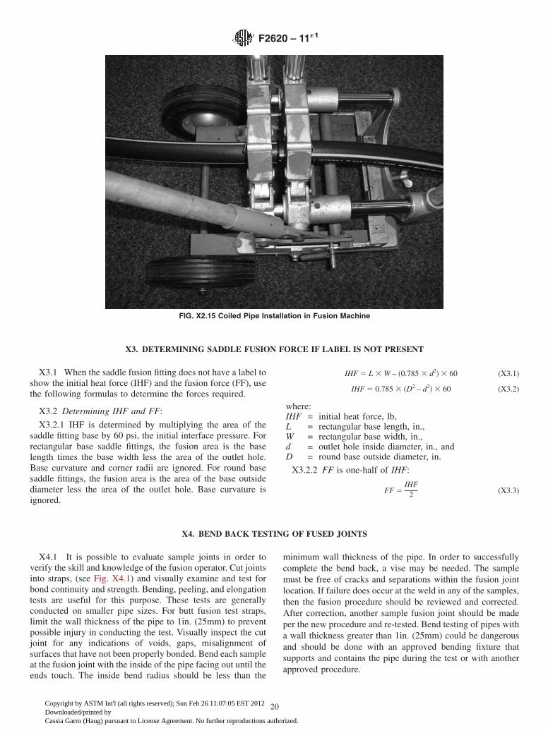
X1.5.2 If there is still a curvature present, install the pipeends in the machine in an “S” configuration with the print linesapproximately 180° apart in order to help gain proper align-ment and help produce a straight joint. See Fig. X2.15.
X1.5.3 If there is still a curvature present, another optionwould be to install a straight piece of pipe between the twocoiled pipes.
NOTE X1.1—Every effort should be made to make the joint perpen-dicular to the axis of the pipe. Visually mitered (angled, off-set) jointsshould be cut out and re-fused (see appearance guidelines in AppendixX2).
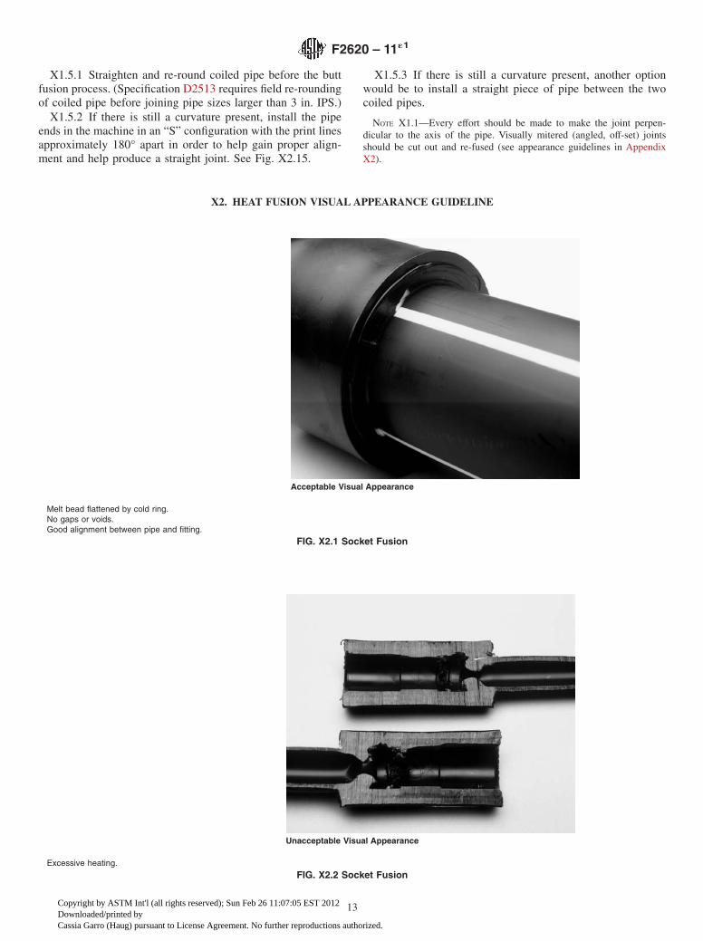
X2. HEAT FUSION VISUAL APPEARANCE GUIDELINE
Acceptable Visual Appearance
Melt bead flattened by cold ring.No gaps or voids.Good alignment between pipe and fitting.
FIG. X2.1 Socket Fusion
Unacceptable Visual Appearance
Excessive heating.
FIG. X2.2 Socket Fusion
F2620 – 11´1
13
Copyright by ASTM Int'l (all rights reserved); Sun Feb 26 11:07:05 EST 2012Downloaded/printed byCassia Garro (Haug) pursuant to License Agreement. No further reproductions authorized.

Unacceptable Visual Appearance
Melt bead not flattened against the fitting/cold ring.Improper insertion depth; no cold ring.Excessive heating.
FIG. X2.3 Socket Fusion
Unacceptable Visual Appearance
Misalignment.
FIG. X2.4 Socket Fusion
F2620 – 11´1
14
Copyright by ASTM Int'l (all rights reserved); Sun Feb 26 11:07:05 EST 2012Downloaded/printed byCassia Garro (Haug) pursuant to License Agreement. No further reproductions authorized.
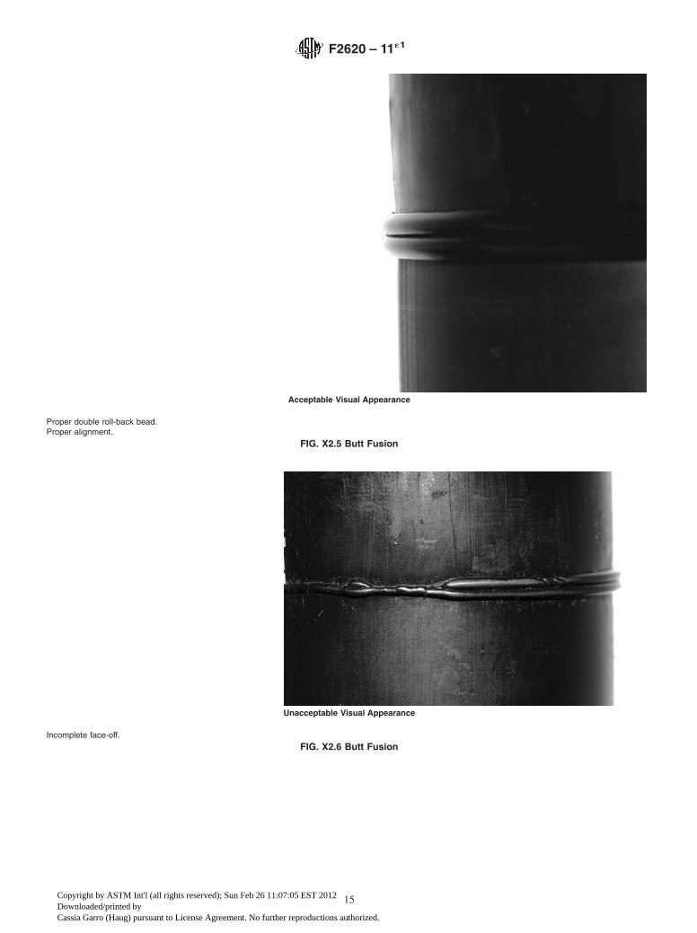
Acceptable Visual Appearance
Proper double roll-back bead.Proper alignment.
FIG. X2.5 Butt Fusion
Unacceptable Visual Appearance
Incomplete face-off.
FIG. X2.6 Butt Fusion
F2620 – 11´1
15
Copyright by ASTM Int'l (all rights reserved); Sun Feb 26 11:07:05 EST 2012Downloaded/printed byCassia Garro (Haug) pursuant to License Agreement. No further reproductions authorized.
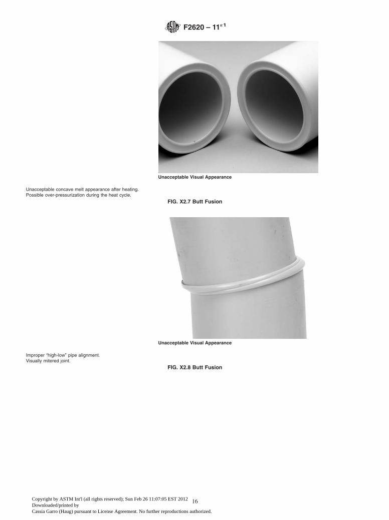
Unacceptable Visual Appearance
Unacceptable concave melt appearance after heating.Possible over-pressurization during the heat cycle.
FIG. X2.7 Butt Fusion
Unacceptable Visual Appearance
Improper “high-low” pipe alignment.Visually mitered joint.
FIG. X2.8 Butt Fusion
F2620 – 11´1
16
Copyright by ASTM Int'l (all rights reserved); Sun Feb 26 11:07:05 EST 2012Downloaded/printed byCassia Garro (Haug) pursuant to License Agreement. No further reproductions authorized.
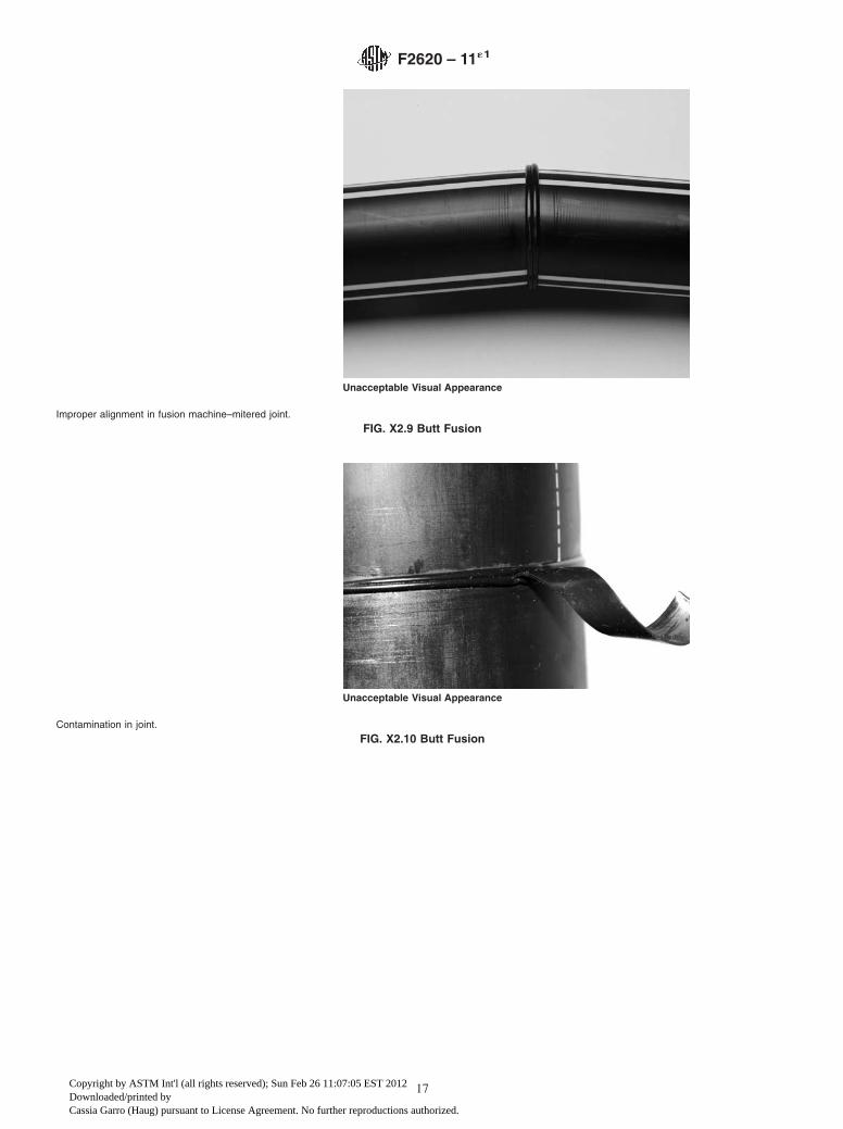
Unacceptable Visual Appearance
Improper alignment in fusion machine–mitered joint.
FIG. X2.9 Butt Fusion
Unacceptable Visual Appearance
Contamination in joint.
FIG. X2.10 Butt Fusion
F2620 – 11´1
17
Copyright by ASTM Int'l (all rights reserved); Sun Feb 26 11:07:05 EST 2012Downloaded/printed byCassia Garro (Haug) pursuant to License Agreement. No further reproductions authorized.
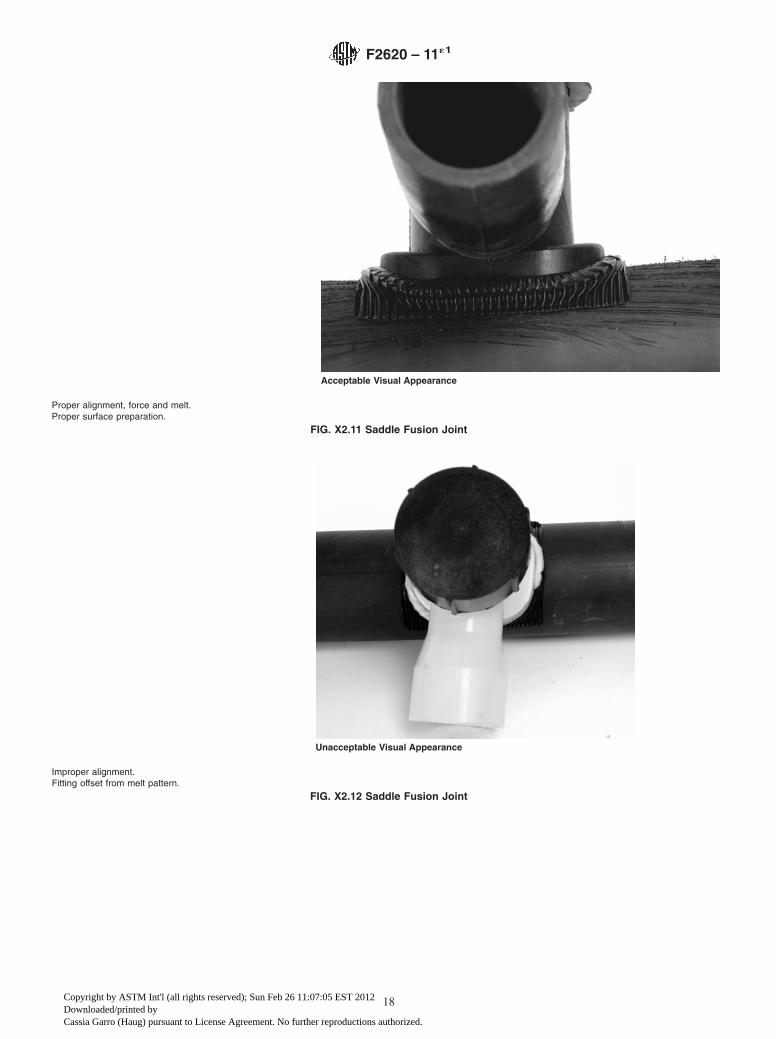
Acceptable Visual Appearance
Proper alignment, force and melt.Proper surface preparation.
FIG. X2.11 Saddle Fusion Joint
Unacceptable Visual Appearance
Improper alignment.Fitting offset from melt pattern.
FIG. X2.12 Saddle Fusion Joint
F2620 – 11´1
18
Copyright by ASTM Int'l (all rights reserved); Sun Feb 26 11:07:05 EST 2012Downloaded/printed byCassia Garro (Haug) pursuant to License Agreement. No further reproductions authorized.
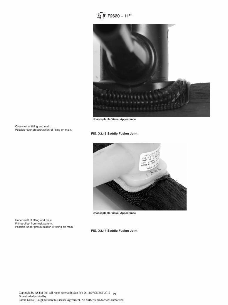
Unacceptable Visual Appearance
Over-melt of fitting and main.Possible over-pressurization of fitting on main.
FIG. X2.13 Saddle Fusion Joint
Unacceptable Visual Appearance
Under-melt of fitting and main.Fitting offset from melt pattern.Possible under-pressurization of fitting on main.
FIG. X2.14 Saddle Fusion Joint
F2620 – 11´1
19
Copyright by ASTM Int'l (all rights reserved); Sun Feb 26 11:07:05 EST 2012Downloaded/printed byCassia Garro (Haug) pursuant to License Agreement. No further reproductions authorized.
X3. DETERMINING SADDLE FUSION FORCE IF LABEL IS NOT PRESENT
X3.1 When the saddle fusion fitting does not have a label toshow the initial heat force (IHF) and the fusion force (FF), usethe following formulas to determine the forces required.
X3.2 Determining IHF and FF:
X3.2.1 IHF is determined by multiplying the area of thesaddle fitting base by 60 psi, the initial interface pressure. Forrectangular base saddle fittings, the fusion area is the baselength times the base width less the area of the outlet hole.Base curvature and corner radii are ignored. For round basesaddle fittings, the fusion area is the area of the base outsidediameter less the area of the outlet hole. Base curvature isignored.
IHF 5 L 3 W – ~0.785 3 d2! 3 60 (X3.1)
IHF 5 0.785 3 ~D2 – d2! 3 60 (X3.2)
where:IHF = initial heat force, lb,L = rectangular base length, in.,W = rectangular base width, in.,d = outlet hole inside diameter, in., andD = round base outside diameter, in.
X3.2.2 FF is one-half of IHF:
FF 5IHF
2 (X3.3)
X4. BEND BACK TESTING OF FUSED JOINTS
X4.1 It is possible to evaluate sample joints in order toverify the skill and knowledge of the fusion operator. Cut jointsinto straps, (see Fig. X4.1) and visually examine and test forbond continuity and strength. Bending, peeling, and elongationtests are useful for this purpose. These tests are generallyconducted on smaller pipe sizes. For butt fusion test straps,limit the wall thickness of the pipe to 1in. (25mm) to preventpossible injury in conducting the test. Visually inspect the cutjoint for any indications of voids, gaps, misalignment ofsurfaces that have not been properly bonded. Bend each sampleat the fusion joint with the inside of the pipe facing out until theends touch. The inside bend radius should be less than the
minimum wall thickness of the pipe. In order to successfullycomplete the bend back, a vise may be needed. The samplemust be free of cracks and separations within the fusion jointlocation. If failure does occur at the weld in any of the samples,then the fusion procedure should be reviewed and corrected.After correction, another sample fusion joint should be madeper the new procedure and re-tested. Bend testing of pipes witha wall thickness greater than 1in. (25mm) could be dangerousand should be done with an approved bending fixture thatsupports and contains the pipe during the test or with anotherapproved procedure.
FIG. X2.15 Coiled Pipe Installation in Fusion Machine
F2620 – 11´1
20
Copyright by ASTM Int'l (all rights reserved); Sun Feb 26 11:07:05 EST 2012Downloaded/printed byCassia Garro (Haug) pursuant to License Agreement. No further reproductions authorized.

ASTM International takes no position respecting the validity of any patent rights asserted in connection with any item mentionedin this standard. Users of this standard are expressly advised that determination of the validity of any such patent rights, and the riskof infringement of such rights, are entirely their own responsibility.
This standard is subject to revision at any time by the responsible technical committee and must be reviewed every five years andif not revised, either reapproved or withdrawn. Your comments are invited either for revision of this standard or for additional standardsand should be addressed to ASTM International Headquarters. Your comments will receive careful consideration at a meeting of theresponsible technical committee, which you may attend. If you feel that your comments have not received a fair hearing you shouldmake your views known to the ASTM Committee on Standards, at the address shown below.
This standard is copyrighted by ASTM International, 100 Barr Harbor Drive, PO Box C700, West Conshohocken, PA 19428-2959,United States. Individual reprints (single or multiple copies) of this standard may be obtained by contacting ASTM at the aboveaddress or at 610-832-9585 (phone), 610-832-9555 (fax), or [email protected] (e-mail); or through the ASTM website(www.astm.org). Permission rights to photocopy the standard may also be secured from the ASTM website (www.astm.org/COPYRIGHT/).
FIG. X4.1 Bent Strap Test Specimen
F2620 – 11´1
21
Copyright by ASTM Int'l (all rights reserved); Sun Feb 26 11:07:05 EST 2012Downloaded/printed byCassia Garro (Haug) pursuant to License Agreement. No further reproductions authorized.