F20/F30 Ferra Series Hydraulic Pumps - Hesselman file2 Concentric AB-F20/F30 PMP-2012-04 Reliable,...
44
Innovation in Hydraulics Concentric AB F20/F30 Ferra Series Hydraulic Pumps
Transcript of F20/F30 Ferra Series Hydraulic Pumps - Hesselman file2 Concentric AB-F20/F30 PMP-2012-04 Reliable,...
Innovation in HydraulicsConcentric AB
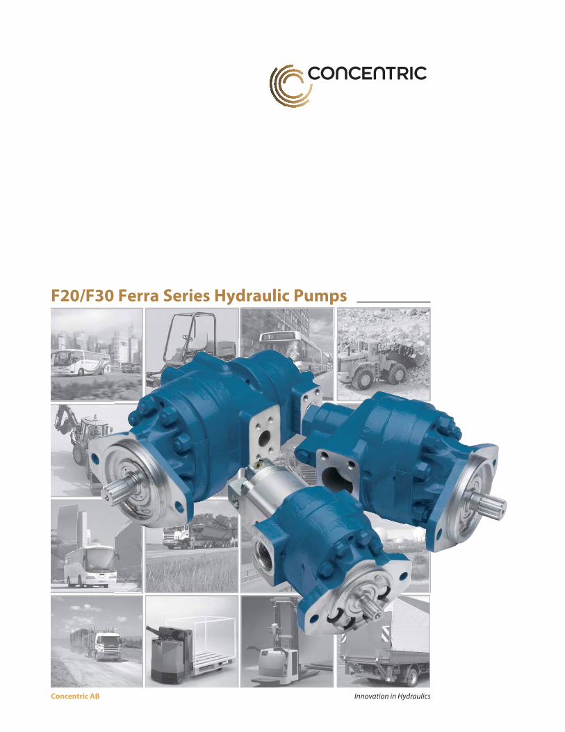
F20/F30 Ferra Series Hydraulic Pumps
Concentric AB-F20/F30 PMP-2012-042
Reliable, efficient, serviceable
design
Concentric external spur gear, posi-tive displacement pumps are offered in single, double, triple and thru-drive versions.
Single and thru-drive pumps are of a three-section modular design. Front and rear covers are cast iron for reliability, strength, and sound reduction. A cast iron center section allows gear tips to generate their own run-in paths, creating minimum radial gear-tip clearance for high volumetric efficiency.
The thru-drive pump is a single pump with a mounting pad and coupling spline in its rear cover, allow-ing a second pump to be mounted and driven in tandem.
The double pump consists of two sin-gle pumps, each having its own outlet port but sharing a common inlet port and input shaft. This compact unit can, therefore, serve two separate hydraulic circuits, or supply greater volume to a single circuit through the combined delivery of both pumps.
Besides offering greater design flexibility to hydraulic system designers, thru-drive and double pumps reduce installation costs since they allow multiple pump operation from a single mounting and drive point. Also, double pumps require only one inlet line, compared to the two required when separate pumps are used.
Convenient, economical porting
arrangements
A large selection of port sizes and positions allows greater system design flexibility, provides the means for reducing costs through simplified plumbing arrangements, and facilitates the interchangeability of Concentric and competitive pumps. SAE 4-bolt split flange ports and SAE straight thread ports are standard.
Choice of shafts, rotation and
couplings
Splined SAE side-fit drive shafts are standard. Other popular shafts are available. Pumps are assembled for either clockwise or counterclockwise rotation.
Thru-drive pumps are provided with output drive couplings that mate with splined SAE side-fit drive shafts.
Meets many mounting
requirements
SAE standard wet flange mountings and single or double shaft seals are available on all pumps. Mounting pads meet SAE standards and are available in several sizes and types to satisfy various mounting requirements and to facilitate interchangeability of Vickers and competitive units.
Double shaft seals are ideal for applications where the pump pilot and shaft extend into a transmission case or crankcase. If either seal fails, the pump fluid remains separated from the transmission or crankcase fluid. Leakage past either seals drains to the exterior of the pump. The dou-ble seal feature thus reduces system
downtime by preventing the mixing of different fluids and providing for visual detection of seal malfunction.
The inlet of the thru-drive pump is open to the pump’s rear coupling area, requiring that mating pumps have a wet-flange mounting. If the rear mounting pad is capped instead of used to mount a pump, it must be sealed to prevent fluid leakage and entrance of air.
Heavy duty construction
The drive gear and drive shaft are one piece construction, as are the driven gear and shaft, to eliminate the poten-tial problems of fretting and stress fatigue associated with two-piece construction. The one-piece design also allows the use of large diameter journals and bearings for greater load-carrying capacity.
Gears are of AISI 8620 alloy steel for greater shaft strength and a stronger gear assembly. Gears have ten teeth to minimize pressure ripple, and gear sides and shaft journals are carburized, hardened, and ground to a fine finish.
The pumps large teflon impregnated bronze bearings are installed in precision bored covers for optimum shaft alignment. They provide a large support area that keeps bearing pressures low enough to handle most indirect drives. For appli-cations imposing very high side loads, consult your Concentric representative.
NOTE: This catalog features our most standard single, double and triple pump capabilities. Other pump options and multiple pump combinations are avail-able. Please contact factory or your Concentric representative for information. See bottom of page 45 for contact information.
DESCRIPTION, FEATURES AND BENEFITS
Pictures on front cover are used with the kind permission of eg: Atlet, BT, Huddig, Scania, Toro and Volvo Construction Equipment.
Concentric AB-F20/F30 PMP-2012-04 3
LONG-LIFE BEARING SYSTEM
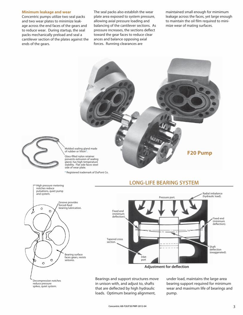
F20 PumpMolded sealing gland made of rubber or Viton*.
Glass-filled nylon retainer prevents extrusion of sealing gland, has high temperature stability. Flat side faces steel side of wear plate.
* Registered trademark of DuPont Co.
High pressure metering notches reduce pulsations, quiet pump and system.
Groove provides forced-feed bearing lubrication.
Bearing surface faces gears, resists seizures.
Decompression notches reduce pressure spikes, quiet system.
Minimum leakage and wear
Concentric pumps utilize two seal packs and two wear plates to minimize leak-age across the end faces of the gears and to reduce wear. During startup, the seal packs mechanically preload and seal a cantilever section of the plates against the ends of the gears.
The seal packs also establish the wear plate area exposed to system pressure, allowing axial pressure loading and balancing of the cantilever sections. As pressure increases, the sections deflect toward the gear faces to reduce clearances and balance opposing axial forces. Running clearances are
maintained small enough for mimimum leakage across the faces, yet large enough to maintain the oil film required to mini-mize wear of mating surfaces.
Radial imbalance(hydraulic load).
Fixed end(minimumdeflection).
Shaftdeflection(exaggerated).
Fixed end(minimumdeflection).
Tapered cross section.
Pressure port.
Adjustment for deflection
Bearings and support structures move in unison with, and adjust to, shafts that are deflected by high hydraulic loads. Optimum bearing alignment,
under load, maintains the large-area bearing support required for minimum wear and maximum life of bearings and pump.
Inletport
Concentric AB-F20/F30 PMP-2012-044
Cover-end pump
Double
pump
model
series
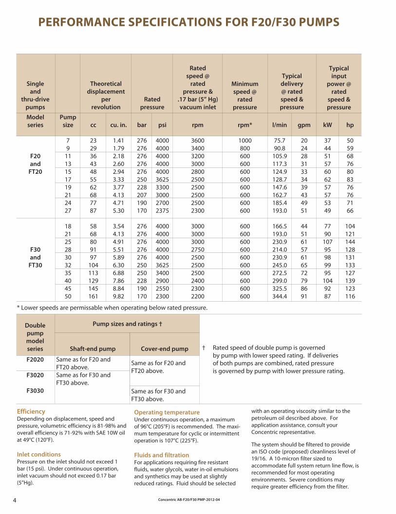
PERFORMANCE SPECIFICATIONS FOR F20/F30 PUMPS
Single
and
thru-drive
pumps
Model
series
F20
and
FT20
F30
and
FT30
Pump
size
79
1113151719212427
18212528303235404550
cc
23293643485562687787
5868809197
104113129145161
cu. in.
1.411.792.182.602.943.333.774.134.715.30
3.544.134.915.515.896.306.887.868.849.82
bar
276276276276276250228207190170
276276276276276250250228190170
psi
4000400040004000400036253300300027002375
4000400040004000400036253400290025502300
rpm
3600340032003000280025002500250025002300
3000300030002750250025002500240023002200
rpm*
1000800600600600600600600600600
600600600600600600600600600600
l/min
75.790.8
105.9117.3124.9128.7147.6162.7185.4193.0
166.5193.0230.9214.0230.9245.0272.5299.0325.5344.4
gpm
20242831333439434951
44516157616572798691
kW
37445157606257575349
7790
10795989995
1049287
hp
50596876808376767166
104121144128131133127139123116
Theoretical
displacement
per
revolution
Rated
pressure
Rated
speed @
rated
pressure &
.17 bar (5” Hg)
vacuum inlet
Minimum
speed @
rated
pressure
Typical
delivery
@ rated
speed &
pressure
Typical
input
power @
rated
speed &
pressure
F2020
F3020
F3030
Same as for F20 and FT20 above.Same as for F30 and FT30 above.
Shaft-end pump
Pump sizes and ratings †
* Lower speeds are permissable when operating below rated pressure.
Same as for F20 and FT20 above.
Same as for F30 and FT30 above.
† Rated speed of double pump is governed by pump with lower speed rating. If deliveries of both pumps are combined, rated pressure is governed by pump with lower pressure rating.
EfficiencyDepending on displacement, speed and pressure, volumetric efficiency is 81-98% and overall efficiency is 71-92% with SAE 10W oil at 49°C (120°F).
Inlet conditionsPressure on the inlet should not exceed 1 bar (15 psi). Under continuous operation, inlet vacuum should not exceed 0.17 bar (5”Hg).
Operating temperatureUnder continuous operation, a maximum of 96°C (205°F) is recommended. The maxi-mum temperature for cyclic or intermittent operation is 107°C (225°F).
Fluids and filtrationFor applications requiring fire resistant fluids, water glycols, water in-oil emulsions and synthetics may be used at slightly reduced ratings. Fluid should be selected
with an operating viscosity similar to the petroleum oil described above. For application assistance, consult your Concentric representative.
The system should be filtered to provide an ISO code (proposed) cleanliness level of 19/16. A 10-micron filter sized to accommodate full system return line flow, is recommended for most operating environments. Severe conditions may require greater efficiency from the filter.
Concentric AB-F20/F30 PMP-2012-04 5
TABLE OF CONTENTS
Description, Features and Benefits ................................................................................. 2 & 3
Specifications and Application Data ......................................................................................4
Installation Dimensions / Model Codes F20 ....................................................................................................................................................................6 - 7 F30 ....................................................................................................................................................................8 - 9 FT20 .............................................................................................................................................................10 - 11 FT30 .............................................................................................................................................................12 - 13 F2009...........................................................................................................................................................14 - 15 F2020...........................................................................................................................................................16 - 17 F3020...........................................................................................................................................................18 - 19 F3030...........................................................................................................................................................20 - 21 F202020 ......................................................................................................................................................22 - 23 F303030 ......................................................................................................................................................24 - 25 F200909 ......................................................................................................................................................26 - 27 F202009 ......................................................................................................................................................28 - 29 F302020 ......................................................................................................................................................30 - 31 F303020 ......................................................................................................................................................32 - 33 FT2020 ........................................................................................................................................................34 - 35 FT3030 ........................................................................................................................................................36 - 37
Mounting Flanges .......................................................................................................................38
Drive Shafts ....................................................................................................................................39
Rear Mounting Flanges for Thru-Drive Pumps .................................................................40
Rear Couplings for Thru-Drive Pumps .................................................................................41
Performance Curves ...................................................................................................................42
Concentric Product Offering ...................................................................................................43
Concentric AB-F20/F30 PMP-2012-046
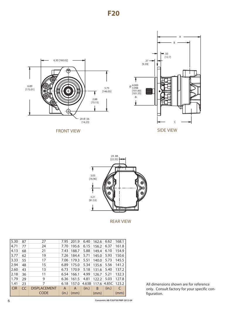
F20
5.304.714.133.773.332.942.602.181.791.41CIR
272421191715131197
DISPLACEMENTCODE
6.30 [160.02]
6.89[175.01]
2X Ø .56[14.23]
5.75[146.05]
2.88[73.15]
FRONT VIEW
.37[9.39]
.50[12.7]
A
B
C
SIDE VIEW
2X .88[22.35]
3.03[76.96]
3.21[81.53]
REAR VIEW
All dimensions shown are for reference only. Consult factory for your specific con-figuration.
168.1161.8154.9150.6145.5141.2137.2132.3127.8123.2
C(mm)
6.626.376.105.935.735.565.405.215.03
4.85C(in.)
162.6156.2149.4145.0140.0135.6131.6126.7122.2117.6
B(mm)
6.406.155.885.715.515.345.184.994.81
4.63B(in.)
201.9195.6188.7184.4179.3175.0170.9166.1161.5157.0
A(mm)
7.957.707.437.267.066.896.736.546.366.18
A(in.)
87776862554843362923CC
Ø 4.0003.998[101.60][101.55]
-B-
Concentric AB-F20/F30 PMP-2012-04 7
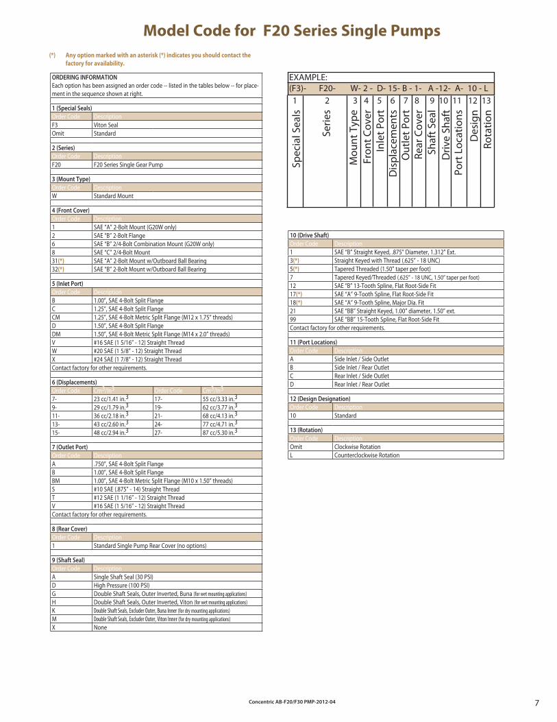
Model Code for F20 Series Single Pumps
EXAMPLE:(F3)- F20- W- 2 - D- 15- B - 1- A -12- A- 10 - L
Spec
ial S
eals
Serie
s
Mou
nt T
ype
Fron
t Cov
erIn
let P
ort
Dis
plac
emen
tsO
utle
t Por
tRe
ar C
over
Shaf
t Sea
lD
rive
Shaf
tPo
rt L
ocat
ions
Des
ign
Rota
tion
1 2 3 4 5 6 7 8 9 10 11 12 13
ORDERING INFORMATION
Each option has been assigned an order code -- listed in the tables below -- for place-ment in the sequence shown at right.
1 (Special Seals)
Order Code DescriptionF3 Viton SealOmit Standard
2 (Series)
Order Code DescriptionF20 F20 Series Single Gear Pump
3 (Mount Type)
Order Code DescriptionW Standard Mount
4 (Front Cover)
Order Code Description1 SAE “A” 2-Bolt Mount (G20W only)2 SAE “B” 2-Bolt Flange6 SAE “B” 2/4-Bolt Combination Mount (G20W only)8 SAE “C” 2/4-Bolt Mount 31(*) SAE “A” 2-Bolt Mount w/Outboard Ball Bearing32(*) SAE “B” 2-Bolt Mount w/Outboard Ball Bearing
5 (Inlet Port)
Order Code DescriptionB 1.00”, SAE 4-Bolt Split FlangeC 1.25”, SAE 4-Bolt Split FlangeCM 1.25”, SAE 4-Bolt Metric Split Flange (M12 x 1.75” threads)D 1.50”, SAE 4-Bolt Split FlangeDM 1.50”, SAE 4-Bolt Metric Split Flange (M14 x 2.0” threads)V #16 SAE (1 5/16” - 12) Straight ThreadW #20 SAE (1 5/8” - 12) Straight ThreadX #24 SAE (1 7/8” - 12) Straight ThreadContact factory for other requirements.
6 (Displacements)
Order Code Cm3/In3 Order Code Cm3/In3
7- 23 cc/1.41 in.3 17- 55 cc/3.33 in.3
9- 29 cc/1.79 in.3 19- 62 cc/3.77 in.3
11- 36 cc/2.18 in.3 21- 68 cc/4.13 in.3
13- 43 cc/2.60 in.3 24- 77 cc/4.71 in.3
15- 48 cc/2.94 in.3 27- 87 cc/5.30 in.3
7 (Outlet Port)
Order Code DescriptionA .750”, SAE 4-Bolt Split FlangeB 1.00”, SAE 4-Bolt Split FlangeBM 1.00”, SAE 4-Bolt Metric Split Flange (M10 x 1.50” threads)S #10 SAE (.875” - 14) Straight ThreadT #12 SAE (1 1/16” - 12) Straight ThreadV #16 SAE (1 5/16” - 12) Straight ThreadContact factory for other requirements.
8 (Rear Cover)
Order Code Description1 Standard Single Pump Rear Cover (no options)
9 (Shaft Seal)
Order Code DescriptionA Single Shaft Seal (30 PSI)D High Pressure (100 PSI)G Double Shaft Seals, Outer Inverted, Buna (for wet mounting applications)H Double Shaft Seals, Outer Inverted, Viton (for wet mounting applications)K Double Shaft Seals, Excluder Outer, Buna Inner (for dry mounting applications)M Double Shaft Seals, Excluder Outer, Viton Inner (for dry mounting applications)X None
10 (Drive Shaft)
Order Code Description1 SAE “B” Straight Keyed, .875” Diameter, 1.312” Ext.3(*) Straight Keyed with Thread (.625” - 18 UNC)5(*) Tapered Threaded (1.50” taper per foot)7 Tapered Keyed/Threaded (.625” - 18 UNC, 1.50” taper per foot)12 SAE “B” 13-Tooth Spline, Flat Root-Side Fit17(*) SAE “A” 9-Tooth Spline, Flat Root-Side Fit18(*) SAE “A” 9-Tooth Spline, Major Dia. Fit21 SAE “BB” Straight Keyed, 1.00” diameter, 1.50” ext.99 SAE “BB” 15-Tooth Spline, Flat Root-Side FitContact factory for other requirements.
11 (Port Locations)
Order Code DescriptionA Side Inlet / Side OutletB Side Inlet / Rear OutletC Rear Inlet / Side OutletD Rear Inlet / Rear Outlet
12 (Design Designation)
Order Code Description10 Standard
13 (Rotation)
Order Code DescriptionOmit Clockwise RotationL Counterclockwise Rotation
(*) Any option marked with an asterisk (*) indicates you should contact the
factory for availability.
Concentric AB-F20/F30 PMP-2012-048
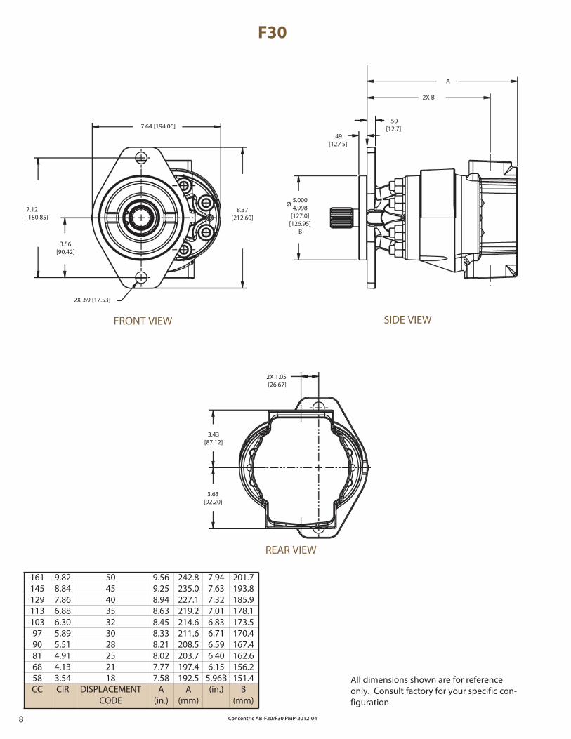
F30
1611451291131039790816858CC
50454035323028252118
DISPLACEMENTCODE
9.569.258.948.638.458.338.218.027.777.58
A(in.)
9.828.847.866.886.305.895.514.914.133.54CIR
7.947.637.327.016.836.716.596.406.15
5.96B(in.)
242.8235.0227.1219.2214.6211.6208.5203.7197.4192.5
A(mm)
201.7193.8185.9178.1173.5170.4167.4162.6156.2151.4
B(mm)
3.63[92.20]
3.43[87.12]
2X 1.05[26.67]
All dimensions shown are for reference only. Consult factory for your specific con-figuration.
7.64 [194.06]
7.12[180.85]
8.37[212.60]
3.56[90.42]
2X .69 [17.53]
FRONT VIEW
.49[12.45]
.50[12.7]
A
2X B
SIDE VIEW
REAR VIEW
5.0004.998
[127.0][126.95]
Ø
-B-
Concentric AB-F20/F30 PMP-2012-04 9
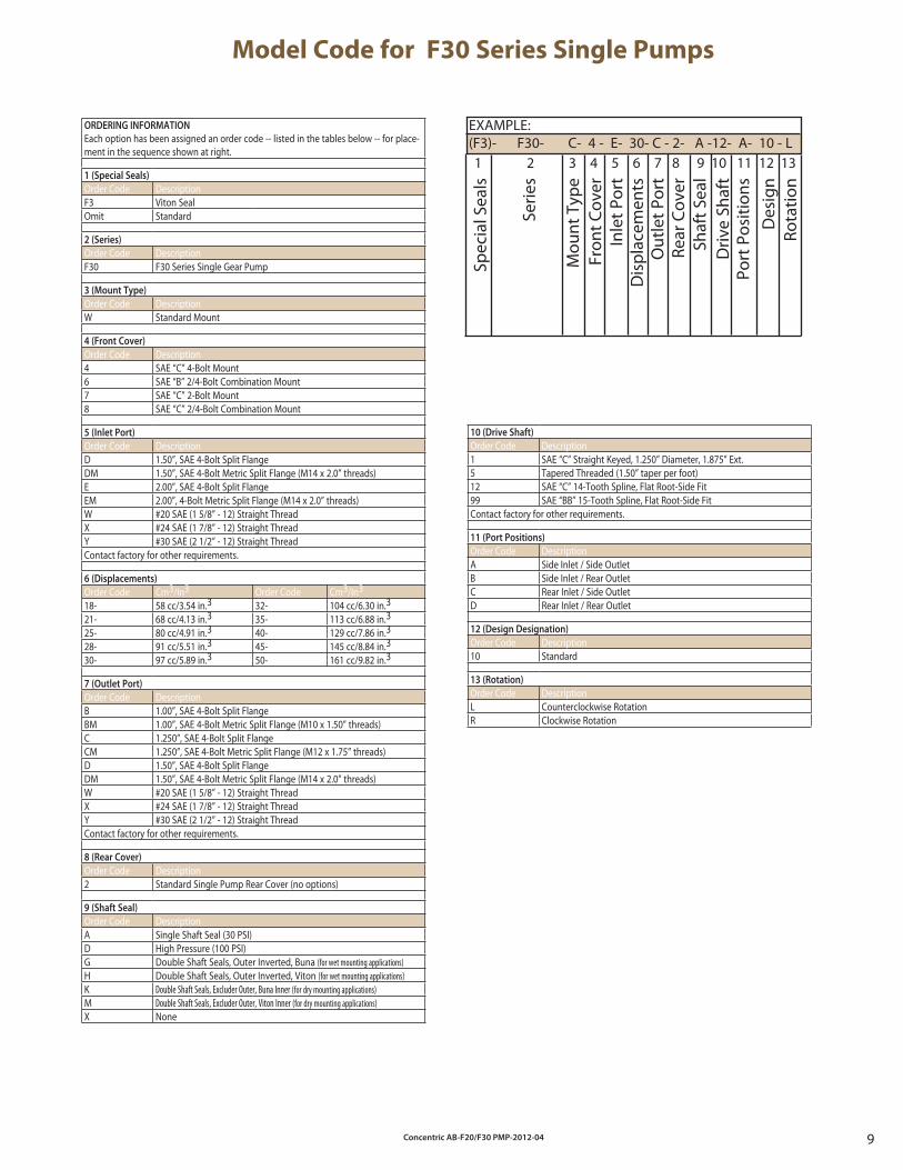
ORDERING INFORMATION
Each option has been assigned an order code -- listed in the tables below -- for place-ment in the sequence shown at right.
1 (Special Seals)
Order Code DescriptionF3 Viton SealOmit Standard
2 (Series)
Order Code DescriptionF30 F30 Series Single Gear Pump
3 (Mount Type)
Order Code DescriptionW Standard Mount
4 (Front Cover)
Order Code Description4 SAE “C” 4-Bolt Mount6 SAE “B” 2/4-Bolt Combination Mount7 SAE “C” 2-Bolt Mount8 SAE “C” 2/4-Bolt Combination Mount
5 (Inlet Port)
Order Code DescriptionD 1.50”, SAE 4-Bolt Split FlangeDM 1.50”, SAE 4-Bolt Metric Split Flange (M14 x 2.0” threads)E 2.00”, SAE 4-Bolt Split FlangeEM 2.00”, 4-Bolt Metric Split Flange (M14 x 2.0” threads)W #20 SAE (1 5/8” - 12) Straight ThreadX #24 SAE (1 7/8” - 12) Straight ThreadY #30 SAE (2 1/2” - 12) Straight ThreadContact factory for other requirements.
6 (Displacements)
Order Code Cm3/In3 Order Code Cm3/In3
18- 58 cc/3.54 in.3 32- 104 cc/6.30 in.3
21- 68 cc/4.13 in.3 35- 113 cc/6.88 in.3
25- 80 cc/4.91 in.3 40- 129 cc/7.86 in.3
28- 91 cc/5.51 in.3 45- 145 cc/8.84 in.3
30- 97 cc/5.89 in.3 50- 161 cc/9.82 in.3
7 (Outlet Port)
Order Code DescriptionB 1.00”, SAE 4-Bolt Split FlangeBM 1.00”, SAE 4-Bolt Metric Split Flange (M10 x 1.50” threads)C 1.250”, SAE 4-Bolt Split FlangeCM 1.250”, SAE 4-Bolt Metric Split Flange (M12 x 1.75” threads)D 1.50”, SAE 4-Bolt Split FlangeDM 1.50”, SAE 4-Bolt Metric Split Flange (M14 x 2.0” threads)W #20 SAE (1 5/8” - 12) Straight ThreadX #24 SAE (1 7/8” - 12) Straight ThreadY #30 SAE (2 1/2” - 12) Straight ThreadContact factory for other requirements.
8 (Rear Cover)
Order Code Description2 Standard Single Pump Rear Cover (no options)
9 (Shaft Seal)
Order Code DescriptionA Single Shaft Seal (30 PSI)D High Pressure (100 PSI)G Double Shaft Seals, Outer Inverted, Buna (for wet mounting applications)H Double Shaft Seals, Outer Inverted, Viton (for wet mounting applications)K Double Shaft Seals, Excluder Outer, Buna Inner (for dry mounting applications)M Double Shaft Seals, Excluder Outer, Viton Inner (for dry mounting applications)X None
Model Code for F30 Series Single Pumps
10 (Drive Shaft)
Order Code Description1 SAE “C” Straight Keyed, 1.250” Diameter, 1.875” Ext.5 Tapered Threaded (1.50” taper per foot)12 SAE “C” 14-Tooth Spline, Flat Root-Side Fit99 SAE “BB” 15-Tooth Spline, Flat Root-Side FitContact factory for other requirements.
11 (Port Positions)
Order Code DescriptionA Side Inlet / Side OutletB Side Inlet / Rear OutletC Rear Inlet / Side OutletD Rear Inlet / Rear Outlet
12 (Design Designation)
Order Code Description10 Standard
13 (Rotation)
Order Code DescriptionL Counterclockwise RotationR Clockwise Rotation
EXAMPLE:(F3)- F30- C- 4 - E- 30- C - 2- A -12- A- 10 - L
Spec
ial S
eals
Serie
s
Mou
nt T
ype
Fron
t Cov
erIn
let P
ort
Dis
plac
emen
tsO
utle
t Por
tRe
ar C
over
Shaf
t Sea
lD
rive
Shaf
tPo
rt P
ositi
ons
Des
ign
Rota
tion
1 2 3 4 5 6 7 8 9 10 11 12 13
Concentric AB-F20/F30 PMP-2012-0410
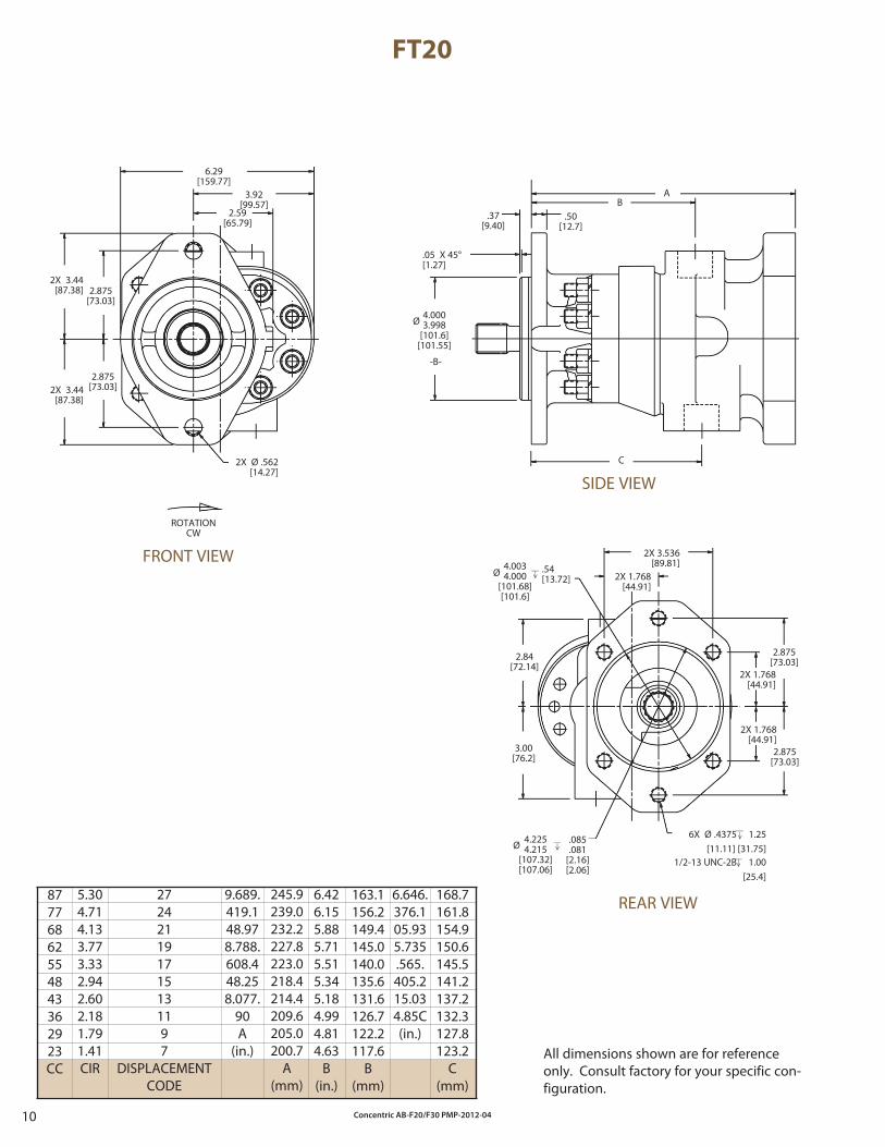
FT20
87776862554843362923CC
245.9239.0232.2227.8223.0218.4214.4209.6205.0200.7
A(mm)
5.304.714.133.773.332.942.602.181.791.41CIR
9.689.419.148.978.788.608.448.258.077.
90A
(in.)
6.426.155.885.715.515.345.184.994.814.63
B(in.)
163.1156.2149.4145.0140.0135.6131.6126.7122.2117.6
B(mm)
6.646.376.105.935.735.565.405.215.034.85C (in.)
168.7161.8154.9150.6145.5141.2137.2132.3127.8123.2
C(mm)
6X Ø .4375 1.25[11.11] [31.75]
Ø
-B-
4.0003.998
[101.6][101.55]
Ø4.0034.000
[101.68][101.6]
__> __ .54[13.72] 2X 1.768
[44.91]
2X 3.536[89.81]
2X 1.768[44.91]
2X 1.768[44.91]
2.875[73.03]
__
> __
1/2-13 UNC-2B 1.00[25.4]
__> __
Ø 4.2254.215
[107.32][107.06]
__> __ .085.081
[2.16][2.06]
3.00[76.2]
2X Ø .562[14.27]
6.29[159.77]
2X 3.44[87.38]
2.875[73.03]
ROTATIONCW
2.875[73.03]
2.84[72.14]
2X 3.44[87.38] 2.875
[73.03]
3.92[99.57]
2.59[65.79]
All dimensions shown are for reference only. Consult factory for your specific con-figuration.
FRONT VIEW
.37[9.40]
.50[12.7]
.05 X 45°[1.27]
AB
C
SIDE VIEW
REAR VIEW272421191715131197
DISPLACEMENTCODE
Concentric AB-F20/F30 PMP-2012-04 11
Model Code for FT20 Series Thru Drive Pumps
EXAMPLE:(F3)- FT20- W- 2 - D- 9- B - 1- A -12- A- 10 - L
Spec
ial S
eals
Serie
s
Mou
nt T
ype
Fron
t Cov
erIn
let P
ort
Dis
plac
emen
tsO
utle
t Por
tRe
ar M
ount
ing
Pad
Shaf
t Sea
lD
rive
Shaf
tRe
ar C
oupl
ing
Des
ign
Rota
tion
1 2 3 4 5 6 7 8 9 10 11 12 13
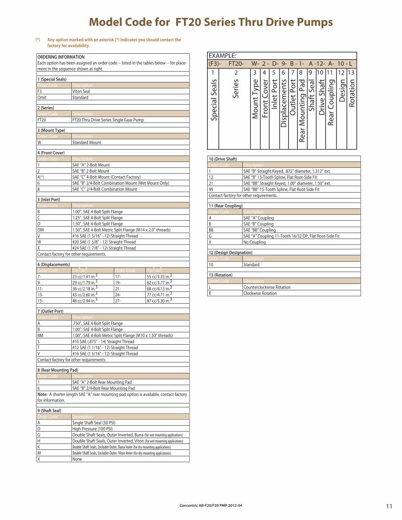
ORDERING INFORMATION
Each option has been assigned an order code -- listed in the tables below -- for place-ment in the sequence shown at right.
1 (Special Seals)
Order Code DescriptionF3 Viton SealOmit Standard
2 (Series)
Order Code DescriptionFT20 FT20 Thru Drive Series Single Gear Pump
3 (Mount Type)
Order Code DescriptionW Standard Mount
4 (Front Cover)
Order Code Description1 SAE “A” 2-Bolt Mount2 SAE “B” 2-Bolt Mount4(*) SAE “C” 4-Bolt Mount (Contact Factory)6 SAE “B” 2/4-Bolt Combination Mount (Wet Mount Only)8 SAE “C” 2/4-Bolt Combination Mount
5 (Inlet Port)
Order Code DescriptionB 1.00”, SAE 4-Bolt Split FlangeC 1.25”, SAE 4-Bolt Split FlangeD 1.50”, SAE 4-Bolt Split FlangeDM 1.50”, SAE 4-Bolt Metric Split Flange (M14 x 2.0” threads)V #16 SAE (1 5/16” - 12) Straight ThreadW #20 SAE (1 5/8” - 12) Straight ThreadX #24 SAE (1 7/8” - 12) Straight ThreadContact factory for other requirements.
6 (Displacements)
Order Code Cm3/In3 Order Code Cm3/In3
7- 23 cc/1.41 in.3 17- 55 cc/3.33 in.3
9- 29 cc/1.79 in.3 19- 62 cc/3.77 in.3
11- 36 cc/2.18 in.3 21- 68 cc/4.13 in.3
13- 43 cc/2.60 in.3 24- 77 cc/4.71 in.3
15- 48 cc/2.94 in.3 27- 87 cc/5.30 in.3
7 (Outlet Port)
Order Code DescriptionA .750”, SAE 4-Bolt Split FlangeB 1.00”, SAE 4-Bolt Split FlangeBM 1.00”, SAE 4-Bolt Metric Split Flange (M10 x 1.50” threads)S #10 SAE (.875” - 14) Straight ThreadT #12 SAE (1 1/16” - 12) Straight ThreadV #16 SAE (1 5/16” - 12) Straight ThreadContact factory for other requirements.
8 (Rear Mounting Pad)
Order Code Description1 SAE “A” 2-Bolt Rear Mounting Pad6 SAE “B” 2/4-Bolt Rear Mounting PadNote: A shorter length SAE “A” rear mounting pad option is available, contact factory for information.
9 (Shaft Seal)
Order Code DescriptionA Single Shaft Seal (30 PSI)D High Pressure (100 PSI)G Double Shaft Seals, Outer Inverted, Buna (for wet mounting applications)H Double Shaft Seals, Outer Inverted, Viton (for wet mounting applications)K Double Shaft Seals, Excluder Outer, Buna Inner (for dry mounting applications)M Double Shaft Seals, Excluder Outer, Viton Inner (for dry mounting applications)X None
10 (Drive Shaft)
Order Code Description1 SAE “B” Straight Keyed, .875” diameter, 1.312” ext.12 SAE “B” 13-Tooth Spline, Flat Root-Side Fit21 SAE “BB” Straight Keyed, 1.00” diameter, 1.50” ext.99 SAE “BB” 15-Tooth Spline, Flat Root-Side FitContact factory for other requirements.
11 (Rear Coupling)
Order Code DescriptionA SAE “A” CouplingB SAE “B” CouplingBB SAE “BB” CouplingG SAE “A” Coupling 11-Tooth 16/32 DP, Flat Root-Side FitX No Coupling
12 (Design Designation)
Order Code Description10 Standard
13 (Rotation)
Order Code DescriptionL Counterclockwise RotationR Clockwise Rotation
(*) Any option marked with an asterisk (*) indicates you should contact the
factory for availability.
Concentric AB-F20/F30 PMP-2012-0412
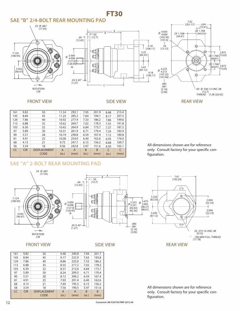
FT30
1611451291131039790816858CC
1611451291131039790816858CC
50454035323028252118
DISPLACEMENTCODE
50454035323028252118
DISPLACEMENTCODE
2.094[53.19]
2.094[53.19]
7.61[193.29]
.49[12.45]
.50[12.7]
5.0004.998
[127.0][126.95]
Ø
-B-
.05 X 45°[1.27]
3.43[87.12]
A 2X 1.768[44.91]
7.92[201.17] 2.91
[73.91]
2.875[73.03]
ROTATIONCW
2X Ø .687[17.45]
7.124[180.95]
3.562[90.47]
B
C
4.18[106.17]
3.25[82.55]
2X 1.768[44.91]
2.875[73.03]2X 1.768
[44.91]
2X 1.768[44.91]
4.18[106.17]
All dimensions shown are for reference only. Consult factory for your specific con-figuration.
FRONT VIEW SIDE VIEW REAR VIEW
SAE “B” 2/4-BOLT REAR MOUNTING PAD
ROTATIONCW
2X Ø .687[17.45]
7.124[180.95]
3.562[90.47]
SIDE VIEW REAR VIEWFRONT VIEW
SAE “A” 2-BOLT REAR MOUNTING PAD
All dimensions shown are for reference only. Consult factory for your specific con-figuration.
11.5411.2310.9210.6210.4310.3110.1910.009.759.56
A(in.)
7.957.647.337.026.846.716.596.406.155.97
B(in.)
Ø 4.0034.000
[102.36][101.6]
__> __
.54[13.72]
Ø4.2254.215
[107.32][107.06]
__> __
.085
.081[2.16][2.06]
6X Ø .500-13 UNC-2B [12.7]THREAD 1.06 [26.92]
__> __
9.828.847.866.886.305.895.514.914.133.54CIR
293.1285.2277.4269.7264.9261.9258.8254.0247.7242.8
A(mm)
201.9194.1186.2178.3173.7170.4167.4162.6156.2151.6
B(mm)
215.4207.5199.6191.8187.2183.9180.8176.0169.7165.1
C(mm)
Ø 5.0004.998
[127.0][126.95]
-B-
3.250[82.55]
3.430[87.12]
2X .375-16 UNC-2B[9.53]
.700 MIN FULL THREAD[17.78]
.05 X 45°[1.27]
.49[12.45]
.50[12.7]
AB
.085
.081[2.16][2.06]
Ø 3.4753.465
[88.27][88.01]
9.489.178.868.558.378.248.127.937.697.50
A(in.)
7.947.637.337.026.846.716.596.406.155.97
B(in.)
9.828.847.866.886.305.895.514.914.133.54CIR
240.8232.9225.0217.2212.6209.3206.2201.4195.3190.5
A(mm)
201.7193.8186.2178.3173.7170.4167.4162.6156.2151.6
B(mm)
8.488.177.867.557.377.247.126.936.686.50
C(in.)
Ø3.2533.251
[82.63][82.56]
Concentric AB-F20/F30 PMP-2012-04 13
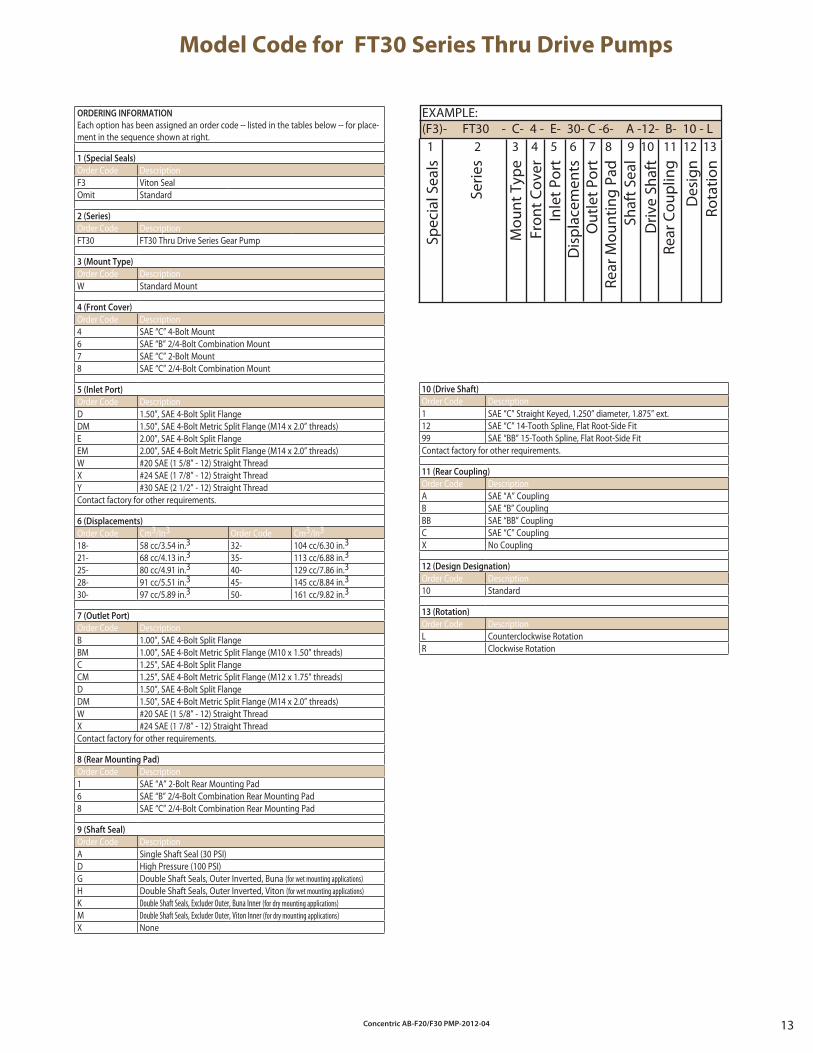
Model Code for FT30 Series Thru Drive Pumps
EXAMPLE:(F3)- FT30 - C- 4 - E- 30- C -6- A -12- B- 10 - L
Spec
ial S
eals
Serie
s
Mou
nt T
ype
Fron
t Cov
erIn
let P
ort
Dis
plac
emen
tsO
utle
t Por
tRe
ar M
ount
ing
Pad
Shaf
t Sea
lD
rive
Shaf
tRe
ar C
oupl
ing
Des
ign
Rota
tion
1 2 3 4 5 6 7 8 9 10 11 12 13
10 (Drive Shaft)
Order Code Description1 SAE “C” Straight Keyed, 1.250” diameter, 1.875” ext.12 SAE “C” 14-Tooth Spline, Flat Root-Side Fit99 SAE “BB” 15-Tooth Spline, Flat Root-Side FitContact factory for other requirements.
11 (Rear Coupling)
Order Code DescriptionA SAE “A” CouplingB SAE “B” CouplingBB SAE “BB” CouplingC SAE “C” CouplingX No Coupling
12 (Design Designation)
Order Code Description10 Standard
13 (Rotation)
Order Code DescriptionL Counterclockwise RotationR Clockwise Rotation
ORDERING INFORMATION
Each option has been assigned an order code -- listed in the tables below -- for place-ment in the sequence shown at right.
1 (Special Seals)
Order Code DescriptionF3 Viton SealOmit Standard
2 (Series)
Order Code DescriptionFT30 FT30 Thru Drive Series Gear Pump
3 (Mount Type)
Order Code DescriptionW Standard Mount
4 (Front Cover)
Order Code Description4 SAE “C” 4-Bolt Mount6 SAE “B” 2/4-Bolt Combination Mount7 SAE “C” 2-Bolt Mount8 SAE “C” 2/4-Bolt Combination Mount
5 (Inlet Port)
Order Code DescriptionD 1.50”, SAE 4-Bolt Split FlangeDM 1.50”, SAE 4-Bolt Metric Split Flange (M14 x 2.0” threads)E 2.00”, SAE 4-Bolt Split FlangeEM 2.00”, SAE 4-Bolt Metric Split Flange (M14 x 2.0” threads)W #20 SAE (1 5/8” - 12) Straight ThreadX #24 SAE (1 7/8” - 12) Straight ThreadY #30 SAE (2 1/2” - 12) Straight ThreadContact factory for other requirements.
6 (Displacements)
Order Code Cm3/In3 Order Code Cm3/In3
18- 58 cc/3.54 in.3 32- 104 cc/6.30 in.3
21- 68 cc/4.13 in.3 35- 113 cc/6.88 in.3
25- 80 cc/4.91 in.3 40- 129 cc/7.86 in.3
28- 91 cc/5.51 in.3 45- 145 cc/8.84 in.3
30- 97 cc/5.89 in.3 50- 161 cc/9.82 in.3
7 (Outlet Port)
Order Code DescriptionB 1.00”, SAE 4-Bolt Split FlangeBM 1.00”, SAE 4-Bolt Metric Split Flange (M10 x 1.50” threads)C 1.25”, SAE 4-Bolt Split FlangeCM 1.25”, SAE 4-Bolt Metric Split Flange (M12 x 1.75” threads)D 1.50”, SAE 4-Bolt Split FlangeDM 1.50”, SAE 4-Bolt Metric Split Flange (M14 x 2.0” threads)W #20 SAE (1 5/8” - 12) Straight ThreadX #24 SAE (1 7/8” - 12) Straight ThreadContact factory for other requirements.
8 (Rear Mounting Pad)
Order Code Description1 SAE “A” 2-Bolt Rear Mounting Pad6 SAE “B” 2/4-Bolt Combination Rear Mounting Pad8 SAE “C” 2/4-Bolt Combination Rear Mounting Pad
9 (Shaft Seal)
Order Code DescriptionA Single Shaft Seal (30 PSI)D High Pressure (100 PSI)G Double Shaft Seals, Outer Inverted, Buna (for wet mounting applications)H Double Shaft Seals, Outer Inverted, Viton (for wet mounting applications)K Double Shaft Seals, Excluder Outer, Buna Inner (for dry mounting applications)M Double Shaft Seals, Excluder Outer, Viton Inner (for dry mounting applications)X None
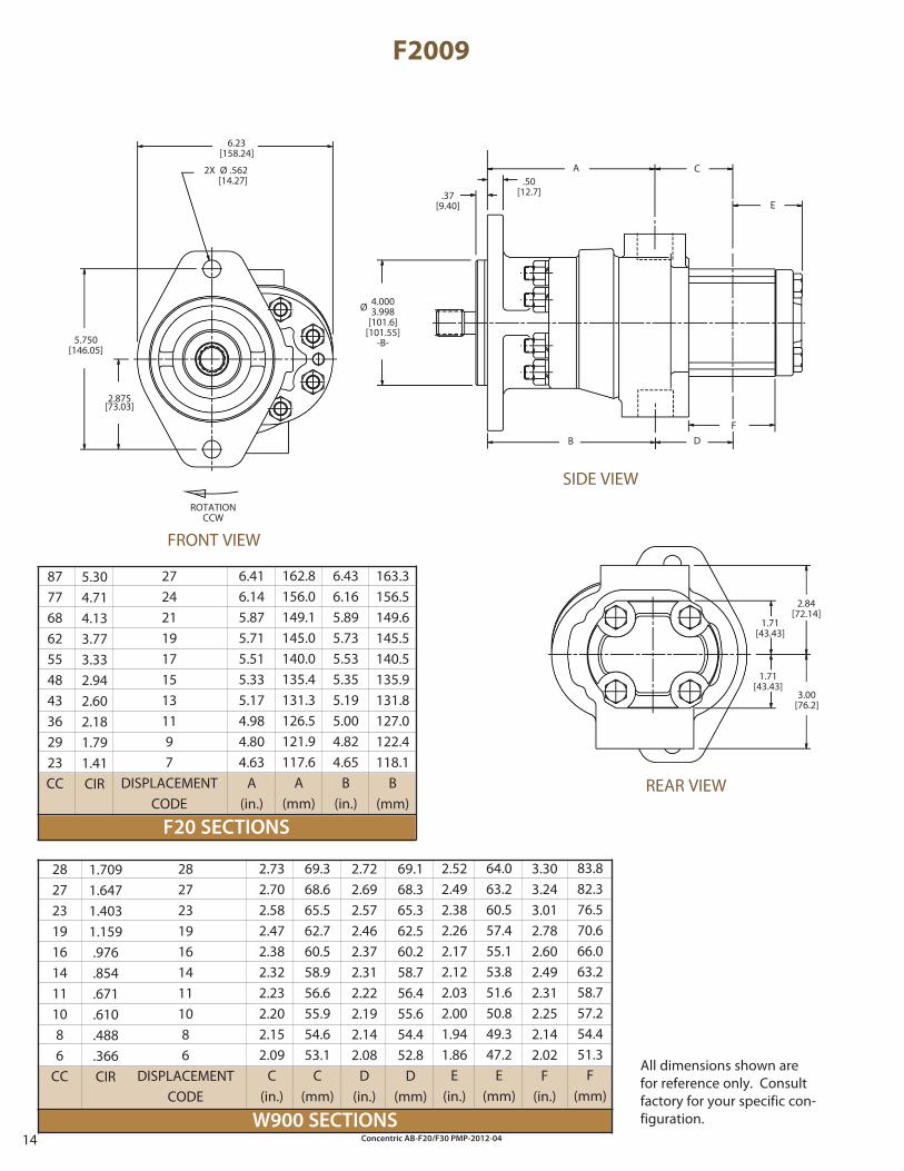
Concentric AB-F20/F30 PMP-2012-0414W900 SECTIONS
F20 SECTIONS
F2009
282723191614111086
DISPLACEMENTCODE
272421191715131197
DISPLACEMENTCODE
.50[12.7].37
[9.40] E
2.84[72.14]
A C
B D
3.00[76.2]
1.71[43.43]
1.71[43.43]
F
All dimensions shown are for reference only. Consult factory for your specific con-figuration.
FRONT VIEW
SIDE VIEW
REAR VIEW
2.522.492.382.262.172.122.032.001.941.86
E(in.)
2.732.702.582.472.382.322.232.202.152.09
C(in.)
2.722.692.572.462.372.312.222.192.142.08
D(in.)
3.303.243.012.782.602.492.312.252.142.02
F(in.)
162.8156.0149.1145.0140.0135.4131.3126.5121.9117.6
A(mm)
6.416.145.875.715.515.335.174.984.804.63
A(in.)
163.3156.5149.6145.5140.5135.9131.8127.0122.4118.1
B(mm)
Ø 4.0003.998
[101.6][101.55]
-B-
ROTATIONCCW
5.750[146.05]
2X Ø .562 [14.27]
6.23[158.24]
2.875[73.03]
6.436.165.895.735.535.355.195.004.824.65
B(in.)
5.304.714.133.773.332.942.602.181.791.41CIR
87776862554843362923CC
1.7091.6471.4031.159.976.854.671.610.488.366CIR
282723191614111086
CC
69.368.665.562.760.558.956.655.954.653.1
C(mm)
69.168.365.362.560.258.756.455.654.452.8
D(mm)
64.063.260.557.455.153.851.650.849.347.2
E(mm)
83.882.376.570.666.063.258.757.254.451.3
F(mm)
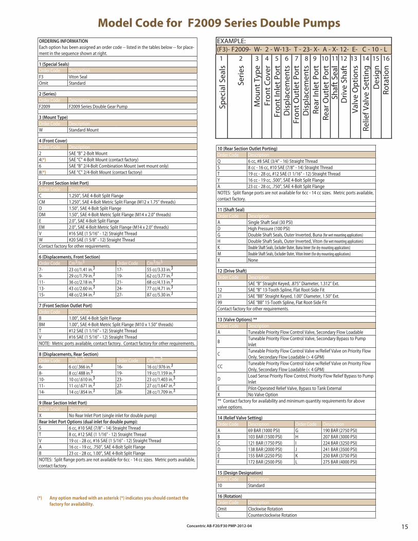
Concentric AB-F20/F30 PMP-2012-04 15
ORDERING INFORMATION
Each option has been assigned an order code -- listed in the tables below -- for place-ment in the sequence shown at right.
1 (Special Seals)
Order Code DescriptionF3 Viton SealOmit Standard
2 (Series)
Order Code DescriptionF2009 F2009 Series Double Gear Pump
3 (Mount Type)
Order Code DescriptionW Standard Mount
4 (Front Cover)
Order Code Description2 SAE “B” 2-Bolt Mount4(*) SAE “C” 4-Bolt Mount (contact factory)6 SAE “B” 2/4-Bolt Combination Mount (wet mount only)8(*) SAE “C” 2/4-Bolt Mount (contact factory)
5 (Front Section Inlet Port)
Order Code DescriptionC 1.250”, SAE 4-Bolt Split FlangeCM 1.250”, SAE 4-Bolt Metric Split Flange (M12 x 1.75” threads)D 1.50”, SAE 4-Bolt Split FlangeDM 1.50”, SAE 4-Bolt Metric Split Flange (M14 x 2.0” threads)E 2.0”, SAE 4-Bolt Split FlangeEM 2.0”, SAE 4-Bolt Metric Split Flange (M14 x 2.0” threads)V #16 SAE (1 5/16” - 12) Straight ThreadW #20 SAE (1 5/8” - 12) Straight ThreadContact factory for other requirements.
6 (Displacements, Front Section)
Order Code Cm3/In3 Order Code Cm3/In3
7- 23 cc/1.41 in.3 17- 55 cc/3.33 in.3
9- 29 cc/1.79 in.3 19- 62 cc/3.77 in.3
11- 36 cc/2.18 in.3 21- 68 cc/4.13 in.3
13- 43 cc/2.60 in.3 24- 77 cc/4.71 in.3
15- 48 cc/2.94 in.3 27- 87 cc/5.30 in.3
7 (Front Section Outlet Port)
Order Code DescriptionB 1.00”, SAE 4-Bolt Split FlangeBM 1.00”, SAE 4-Bolt Metric Split Flange (M10 x 1.50” threads)T #12 SAE (1 1/16” - 12) Straight ThreadV #16 SAE (1 5/16” - 12) Straight ThreadNOTE: Metric ports available, contact factory. Contact factory for other requirements.
8 (Displacements, Rear Section)
Order Code Cm3/In3 Order Code Cm3/In3
6- 6 cc/.366 in.3 16- 16 cc/.976 in.3
8- 8 cc/.488 in.3 19- 19 cc/1.159 in.3
10- 10 cc/.610 in.3 23- 23 cc/1.403 in.3
11- 11 cc/.671 in.3 27- 27 cc/1.647 in.3
14- 14 cc/.854 in.3 28- 28 cc/1.709 in.3
9 (Rear Section Inlet Port)
Order Code DescriptionX No Rear Inlet Port (single inlet for double pump)Rear Inlet Port Options (dual inlet for double pump):
S 6 cc, #10 SAE (7/8” - 14) Straight ThreadT 8 cc, #12 SAE (1 1/16” - 12) Straight ThreadV 19 cc - 28 cc, #16 SAE (1 5/16” - 12) Straight ThreadA 16 cc - 19 cc, .750”, SAE 4-Bolt Split FlangeB 23 cc - 28 cc, 1.00”, SAE 4-Bolt Split FlangeNOTES: Split flange ports are not available for 6cc - 14 cc sizes. Metric ports available, contact factory.
Model Code for F2009 Series Double Pumps
EXAMPLE:(F3)- F2009- W- 2 - W-13- T - 23- X- A - X- 12- E- C - 10 - L
Spec
ial S
eals
Serie
s
Mou
nt T
ype
Fron
t Cov
erFr
ont I
nlet
Por
tD
ispl
acem
ents
Fron
t Out
let P
ort
Dis
plac
emen
tsRe
ar In
let P
ort
Rear
Out
let P
ort
Driv
e Sh
aft
Valv
e O
ptio
nsRe
lief V
alve
Set
ting
1 2 3 4 5 6 7 8 9 10 11 12 13 14 15 16
Des
ign
Rota
tion
Shaf
t Sea
l
10 (Rear Section Outlet Porting)
Order Code DescriptionQ 6 cc, #8 SAE (3/4” - 16) Straight ThreadS 8 cc - 16 cc, #10 SAE (7/8” - 14) Straight ThreadT 19 cc - 28 cc, #12 SAE (1 1/16” - 12) Straight ThreadY 16 cc - 19 cc, .500”, SAE 4-Bolt Split FlangeA 23 cc - 28 cc, .750”, SAE 4-Bolt Split FlangeNOTES: Split flange ports are not available for 6cc - 14 cc sizes. Metric ports available, contact factory.
11 (Shaft Seal)
Order Code DescriptionA Single Shaft Seal (30 PSI)D High Pressure (100 PSI)G Double Shaft Seals, Outer Inverted, Buna (for wet mounting applications)H Double Shaft Seals, Outer Inverted, Viton (for wet mounting applications)K Double Shaft Seals, Excluder Outer, Buna Inner (for dry mounting applications)M Double Shaft Seals, Excluder Outer, Viton Inner (for dry mounting applications)X None
12 (Drive Shaft)
Order Code Description1 SAE “B” Straight Keyed, .875” Diameter, 1.312” Ext.12 SAE “B” 13-Tooth Spline, Flat Root-Side Fit21 SAE “BB” Straight Keyed, 1.00” Diameter, 1.50” Ext.99 SAE “BB” 15-Tooth Spline, Flat Root-Side FitContact factory for other requirements.
13 (Valve Options) **
Order Code DescriptionA Tuneable Priority Flow Control Valve, Secondary Flow Loadable
B Tuneable Priority Flow Control Valve, Secondary Bypass to Pump Inlet
C Tuneable Priority Flow Control Valve w/Relief Valve on Priority Flow Only, Secondary Flow Loadable (> 4 GPM)
CC Tuneable Priority Flow Control Valve w/Relief Valve on Priority Flow Only, Secondary Flow Loadable (< 4 GPM)
D Load Sense Priority Flow Control, Priority Flow Relief Bypass to Pump Inlet
E Pilot-Operated Relief Valve, Bypass to Tank ExternalX No Valve Option** Contact factory for availability and minimum quantity requirements for above valve options.
14 (Relief Valve Setting)
Order Code Description Order Code DescriptionA 69 BAR (1000 PSI) G 190 BAR (2750 PSI)B 103 BAR (1500 PSI) H 207 BAR (3000 PSI)C 121 BAR (1750 PSI) I 224 BAR (3250 PSI)D 138 BAR (2000 PSI) J 241 BAR (3500 PSI)E 155 BAR (2250 PSI) K 250 BAR (3750 PSI)F 172 BAR (2500 PSI) L 275 BAR (4000 PSI)
15 (Design Designation)
Order Code Description10 Standard
16 (Rotation)
Order Code DescriptionOmit Clockwise RotationL Counterclockwise Rotation
(*) Any option marked with an asterisk (*) indicates you should contact the
factory for availability.
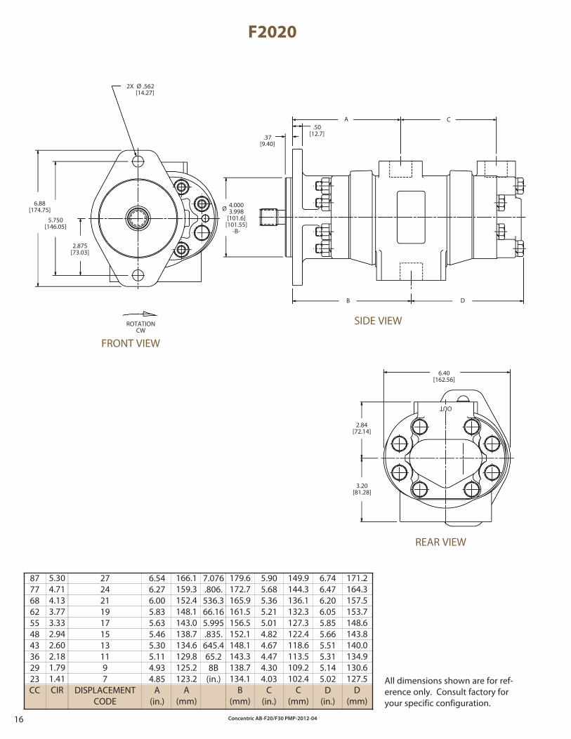
Concentric AB-F20/F30 PMP-2012-0416
F2020
87776862554843362923CC
272421191715131197
DISPLACEMENTCODE
.50[12.7]
B D
ROTATIONCW
2X Ø .562 [14.27]
6.88[174.75]
5.750[146.05]
2.875[73.03]
A C
.37[9.40]
All dimensions shown are for ref-erence only. Consult factory for your specific configuration.
FRONT VIEW
SIDE VIEW
REAR VIEW
179.6172.7165.9161.5156.5152.1148.1143.3138.7134.1
B(mm)
166.1159.3152.4148.1143.0138.7134.6129.8125.2123.2
A(mm)
7.076.806.536.366.165.995.835.645.465.28B
(in.)
6.546.276.005.835.635.465.305.114.934.85
A(in.)
5.905.685.365.215.014.824.674.474.304.03
C(in.)
Ø 4.0003.998
[101.6][101.55]
-B-
OUT
2.84[72.14]
3.20[81.28]
6.40[162.56]
6.746.476.206.055.855.665.515.315.145.02
D(in.)
5.304.714.133.773.332.942.602.181.791.41CIR
149.9144.3136.1132.3127.3122.4118.6113.5109.2102.4
C(mm)
171.2164.3157.5153.7148.6143.8140.0134.9130.6127.5
D(mm)
Concentric AB-F20/F30 PMP-2012-04 17
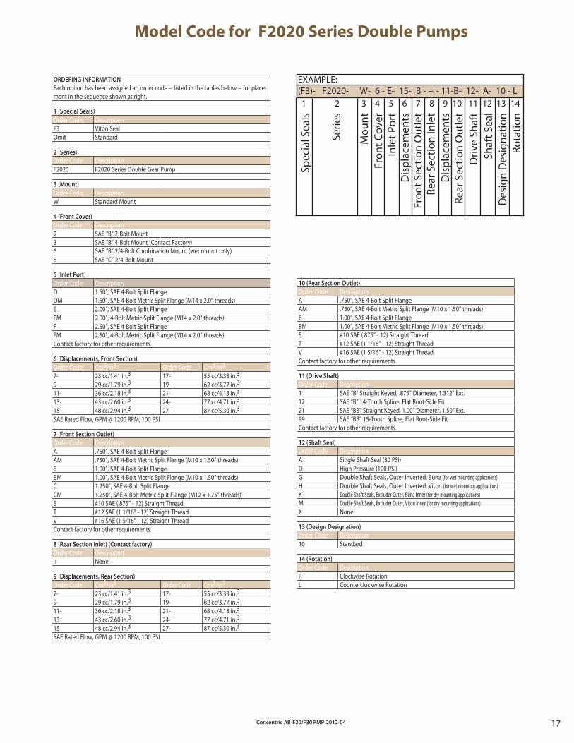
Model Code for F2020 Series Double Pumps
EXAMPLE:(F3)- F2020- W- 6 - E- 15- B - + - 11-B- 12- A- 10 - L
Spec
ial S
eals
Serie
s
Mou
nt
Fron
t Cov
erIn
let P
ort
Dis
plac
emen
tsFr
ont S
ectio
n O
utle
t
Dis
plac
emen
tsRe
ar S
ectio
n O
utle
t D
rive
Shaf
tSh
aft S
eal
Des
ign
Des
igna
tion
Rota
tion
1 2 3 4 5 6 7 8 9 10 11 12 13 14
Rear
Sec
tion
Inle
t
ORDERING INFORMATION
Each option has been assigned an order code -- listed in the tables below -- for place-ment in the sequence shown at right.
1 (Special Seals)
Order Code DescriptionF3 Viton SealOmit Standard
2 (Series)
Order Code DescriptionF2020 F2020 Series Double Gear Pump
3 (Mount)
Order Code DescriptionW Standard Mount
4 (Front Cover)
Order Code Description2 SAE “B” 2-Bolt Mount3 SAE “B” 4-Bolt Mount (Contact Factory)6 SAE “B” 2/4-Bolt Combination Mount (wet mount only)8 SAE “C” 2/4-Bolt Mount
5 (Inlet Port)
Order Code DescriptionD 1.50”, SAE 4-Bolt Split FlangeDM 1.50”, SAE 4-Bolt Metric Split Flange (M14 x 2.0” threads)E 2.00”, SAE 4-Bolt Split FlangeEM 2.00”, 4-Bolt Metric Split Flange (M14 x 2.0” threads)F 2.50”, SAE 4-Bolt Split FlangeFM 2.50”, 4-Bolt Metric Split Flange (M14 x 2.0” threads)Contact factory for other requirements.
6 (Displacements, Front Section)
Order Code Cm3/In3 Order Code Cm3/In3
7- 23 cc/1.41 in.3 17- 55 cc/3.33 in.3
9- 29 cc/1.79 in.3 19- 62 cc/3.77 in.3
11- 36 cc/2.18 in.3 21- 68 cc/4.13 in.3
13- 43 cc/2.60 in.3 24- 77 cc/4.71 in.3
15- 48 cc/2.94 in.3 27- 87 cc/5.30 in.3
SAE Rated Flow, GPM @ 1200 RPM, 100 PSI
7 (Front Section Outlet)
Order Code DescriptionA .750”, SAE 4-Bolt Split FlangeAM .750”, SAE 4-Bolt Metric Split Flange (M10 x 1.50” threads)B 1.00”, SAE 4-Bolt Split FlangeBM 1.00”, SAE 4-Bolt Metric Split Flange (M10 x 1.50” threads)C 1.250”, SAE 4-Bolt Split FlangeCM 1.250”, SAE 4-Bolt Metric Split Flange (M12 x 1.75” threads)S #10 SAE (.875” - 12) Straight ThreadT #12 SAE (1 1/16” - 12) Straight ThreadV #16 SAE (1 5/16” - 12) Straight ThreadContact factory for other requirements.
8 (Rear Section Inlet) (Contact factory)
Order Code Description+ None
9 (Displacements, Rear Section)
Order Code Cm3/In3 Order Code Cm3/In3
7- 23 cc/1.41 in.3 17- 55 cc/3.33 in.3
9- 29 cc/1.79 in.3 19- 62 cc/3.77 in.3
11- 36 cc/2.18 in.3 21- 68 cc/4.13 in.3
13- 43 cc/2.60 in.3 24- 77 cc/4.71 in.3
15- 48 cc/2.94 in.3 27- 87 cc/5.30 in.3
SAE Rated Flow, GPM @ 1200 RPM, 100 PSI
10 (Rear Section Outlet)
Order Code DescriptionA .750”, SAE 4-Bolt Split FlangeAM .750”, SAE 4-Bolt Metric Split Flange (M10 x 1.50” threads)B 1.00”, SAE 4-Bolt Split FlangeBM 1.00”, SAE 4-Bolt Metric Split Flange (M10 x 1.50” threads)S #10 SAE (.875” - 12) Straight ThreadT #12 SAE (1 1/16” - 12) Straight ThreadV #16 SAE (1 5/16” - 12) Straight ThreadContact factory for other requirements.
11 (Drive Shaft)
Order Code Description1 SAE “B” Straight Keyed, .875” Diameter, 1.312” Ext.12 SAE “B” 14-Tooth Spline, Flat Root-Side Fit21 SAE “BB” Straight Keyed, 1.00” Diameter, 1.50” Ext.99 SAE “BB” 15-Tooth Spline, Flat Root-Side FitContact factory for other requirements.
12 (Shaft Seal)
Order Code DescriptionA Single Shaft Seal (30 PSI)D High Pressure (100 PSI)G Double Shaft Seals, Outer Inverted, Buna (for wet mounting applications)H Double Shaft Seals, Outer Inverted, Viton (for wet mounting applications)K Double Shaft Seals, Excluder Outer, Buna Inner (for dry mounting applications)M Double Shaft Seals, Excluder Outer, Viton Inner (for dry mounting applications)X None
13 (Design Designation)
Order Code Description10 Standard
14 (Rotation)
Order Code DescriptionR Clockwise RotationL Counterclockwise Rotation
Concentric AB-F20/F30 PMP-2012-0418
F20 SECTIONS
87776862554843362923CC
F30 SECTIONS
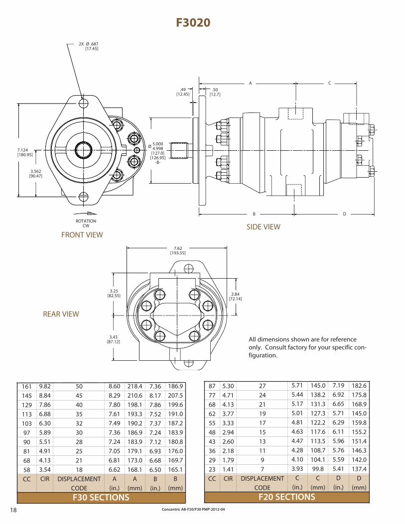
F3020
1611451291131039790816858CC
272421191715131197
DISPLACEMENTCODE
50454035323028252118
DISPLACEMENTCODE
182.6175.8168.9145.0159.8155.2151.4146.3142.0137.4
D(mm)
5.304.714.133.773.332.942.602.181.791.41CIR
5.715.445.175.014.814.634.474.284.103.93
C(in.)
7.196.926.655.716.296.115.965.765.595.41
D(in.)
8.608.297.807.617.497.367.247.056.816.62
A(in.)
7.368.177.867.527.377.247.126.936.686.50
B(in.)
ROTATIONCW
2X Ø .687[17.45]
7.124[180.95]
3.562[90.47]
7.62[193.55]
3.25[82.55]
3.43[87.12]
2.84[72.14]
9.828.847.866.886.305.895.514.914.133.54CIR
218.4210.6198.1193.3190.2186.9183.9179.1173.0168.1
A(mm)
186.9207.5199.6191.0187.2183.9180.8176.0169.7165.1
B(mm)
145.0138.2131.3127.3122.2117.6113.5108.7104.199.8
C(mm)
All dimensions shown are for reference only. Consult factory for your specific con-figuration.
.50[12.7]
.49[12.45]
A C
DB
Ø 5.0004.998
[127.0][126.95]
-B-
FRONT VIEWSIDE VIEW
REAR VIEW
Concentric AB-F20/F30 PMP-2012-04 19
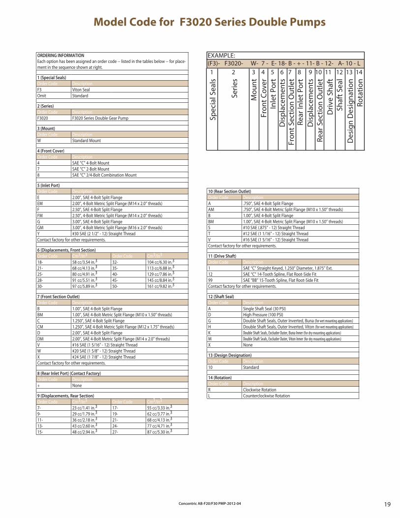
Model Code for F3020 Series Double Pumps
EXAMPLE:(F3)- F3020- W- 7 - E- 18- B - + - 11- B - 12- A- 10 - L
Spec
ial S
eals
Serie
s
Mou
nt
Fron
t Cov
erIn
let P
ort
Dis
plac
emen
tsFr
ont S
ectio
n O
utle
t
Dis
plac
emen
tsRe
ar S
ectio
n O
utle
t D
rive
Shaf
tSh
aft S
eal
Des
ign
Des
igna
tion
Rota
tion
1 2 3 4 5 6 7 8 9 10 11 12 13 14
Rear
Inle
t Por
t
10 (Rear Section Outlet)
Order Code DescriptionA .750”, SAE 4-Bolt Split FlangeAM .750”, SAE 4-Bolt Metric Split Flange (M10 x 1.50” threads)B 1.00”, SAE 4-Bolt Split FlangeBM 1.00”, SAE 4-Bolt Metric Split Flange (M10 x 1.50” threads)S #10 SAE (.875” - 12) Straight ThreadT #12 SAE (1 1/16” - 12) Straight ThreadV #16 SAE (1 5/16” - 12) Straight ThreadContact factory for other requirements.
11 (Drive Shaft)
Order Code Description1 SAE “C” Straight Keyed, 1.250” Diameter, 1.875” Ext.12 SAE “C” 14-Tooth Spline, Flat Root-Side Fit99 SAE “BB” 15-Tooth Spline, Flat Root-Side FitContact factory for other requirements.
12 (Shaft Seal)
Order Code DescriptionA Single Shaft Seal (30 PSI)D High Pressure (100 PSI)G Double Shaft Seals, Outer Inverted, Buna (for wet mounting applications)H Double Shaft Seals, Outer Inverted, Viton (for wet mounting applications)K Double Shaft Seals, Excluder Outer, Buna Inner (for dry mounting applications)M Double Shaft Seals, Excluder Outer, Viton Inner (for dry mounting applications)X None
13 (Design Designation)
Order Code Description10 Standard
14 (Rotation)
Order Code DescriptionR Clockwise RotationL Counterclockwise Rotation
ORDERING INFORMATION
Each option has been assigned an order code -- listed in the tables below -- for place-ment in the sequence shown at right.
1 (Special Seals)
Order Code DescriptionF3 Viton SealOmit Standard
2 (Series)
Order Code DescriptionF3020 F3020 Series Double Gear Pump
3 (Mount)
Order Code DescriptionW Standard Mount
4 (Front Cover)
Order Code Description4 SAE “C” 4-Bolt Mount 7 SAE “C” 2-Bolt Mount 8 SAE “C” 2/4-Bolt Combination Mount
5 (Inlet Port)
Order Code DescriptionE 2.00”, SAE 4-Bolt Split FlangeEM 2.00”, 4-Bolt Metric Split Flange (M14 x 2.0” threads)F 2.50”, SAE 4-Bolt Split FlangeFM 2.50”, 4-Bolt Metric Split Flange (M14 x 2.0” threads)G 3.00”, SAE 4-Bolt Split FlangeGM 3.00”, 4-Bolt Metric Split Flange (M16 x 2.0” threads)Y #30 SAE (2 1/2” - 12) Straight ThreadContact factory for other requirements.
6 (Displacements, Front Section)
Order Code Cm3/In3 Order Code Cm3/In3
18- 58 cc/3.54 in.3 32- 104 cc/6.30 in.3
21- 68 cc/4.13 in.3 35- 113 cc/6.88 in.3
25- 80 cc/4.91 in.3 40- 129 cc/7.86 in.3
28- 91 cc/5.51 in.3 45- 145 cc/8.84 in.3
30- 97 cc/5.89 in.3 50- 161 cc/9.82 in.3
7 (Front Section Outlet)
Order Code DescriptionB 1.00”, SAE 4-Bolt Split FlangeBM 1.00”, SAE 4-Bolt Metric Split Flange (M10 x 1.50” threads)C 1.250”, SAE 4-Bolt Split FlangeCM 1.250”, SAE 4-Bolt Metric Split Flange (M12 x 1.75” threads)D 2.00”, SAE 4-Bolt Split FlangeDM 2.00”, SAE 4-Bolt Metric Split Flange (M14 x 2.0” threads)V #16 SAE (1 5/16” - 12) Straight ThreadW #20 SAE (1 5/8” - 12) Straight ThreadX #24 SAE (1 7/8” - 12) Straight ThreadContact factory for other requirements.
8 (Rear Inlet Port) (Contact Factory)
Order Code Description+ None
9 (Displacements, Rear Section)
Order Code Cm3/In3 Order Code Cm3/In3
7- 23 cc/1.41 in.3 17- 55 cc/3.33 in.3
9- 29 cc/1.79 in.3 19- 62 cc/3.77 in.3
11- 36 cc/2.18 in.3 21- 68 cc/4.13 in.3
13- 43 cc/2.60 in.3 24- 77 cc/4.71 in.3
15- 48 cc/2.94 in.3 27- 87 cc/5.30 in.3
Concentric AB-F20/F30 PMP-2012-0420
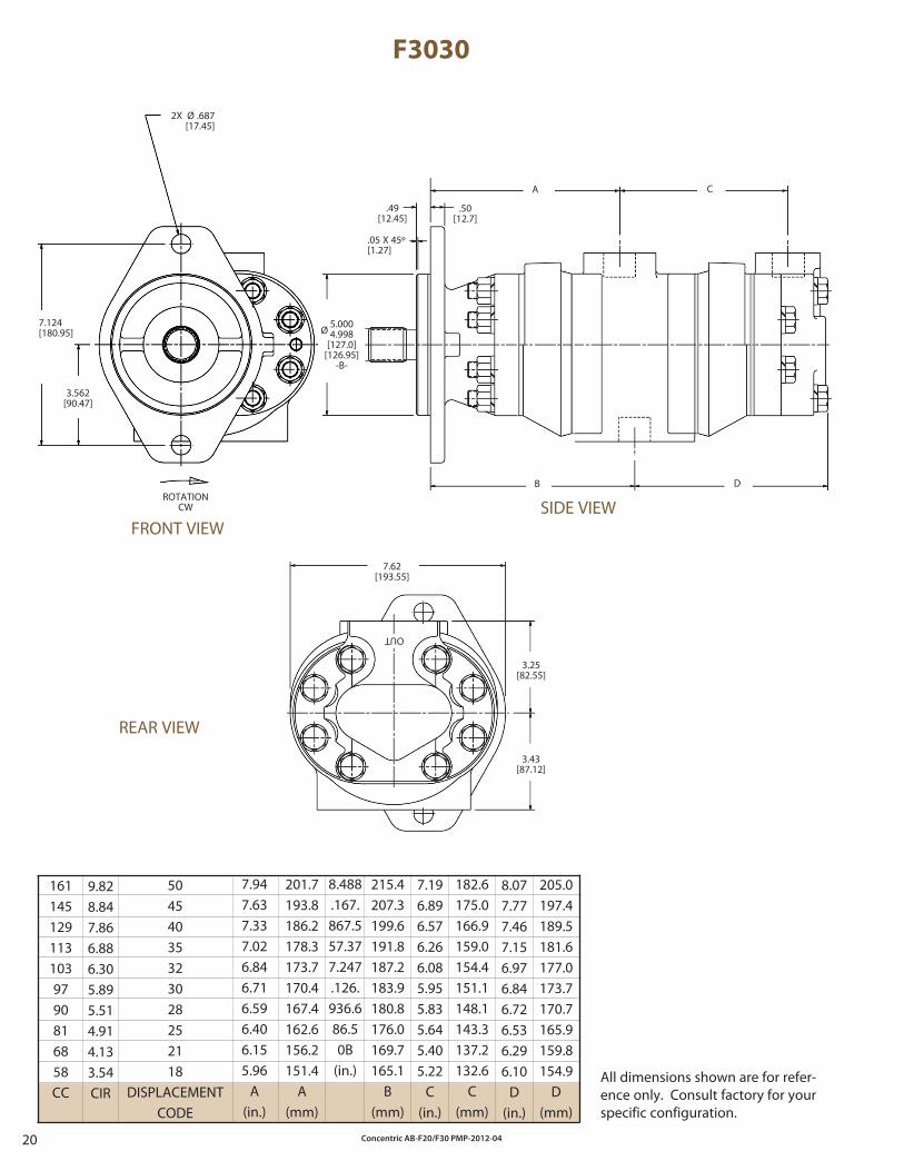
F3030
1611451291131039790816858CC
50454035323028252118
DISPLACEMENTCODE
8.488.167.867.557.377.247.126.936.686.50B
(in.)
7.947.637.337.026.846.716.596.406.155.96
A(in.)
7.196.896.576.266.085.955.835.645.405.22
C(in.)
ROTATIONCW
2X Ø .687[17.45]
7.124[180.95]
3.562[90.47]
Ø5.0004.998
[127.0][126.95]
-B-
OUT
3.43[87.12]
3.25[82.55]
7.62[193.55]
8.077.777.467.156.976.846.726.536.296.10
D(in.)
9.828.847.866.886.305.895.514.914.133.54CIR
201.7193.8186.2178.3173.7170.4167.4162.6156.2151.4
A(mm)
215.4207.3199.6191.8187.2183.9180.8176.0169.7165.1
B(mm)
182.6175.0166.9159.0154.4151.1148.1143.3137.2132.6
C(mm)
205.0197.4189.5181.6177.0173.7170.7165.9159.8154.9
D(mm)
.05 X 45º[1.27]
.49[12.45]
.50[12.7]
A C
DB
SIDE VIEW
All dimensions shown are for refer-ence only. Consult factory for your specific configuration.
FRONT VIEW
REAR VIEW

Concentric AB-F20/F30 PMP-2012-04 21
Model Code for F3030 Series Double Pumps
EXAMPLE:(F3)- F3030- W- 7 - E- 30- B - + - 30- B - 12- A- 10 - L
Spec
ial S
eals
Serie
s
Mou
nt
Fron
t Cov
erIn
let P
ort
Dis
plac
emen
tsFr
ont O
utle
t Por
t
Dis
plac
emen
tsRe
ar O
utle
t Por
tD
rive
Shaf
tSh
aft S
eal
Des
ign
Des
igna
tion
Rota
tion
1 2 3 4 5 6 7 8 9 10 11 12 13 14
Rear
Inle
t Por
t
10 (Rear Outlet Port)
Order Code DescriptionA .750”, SAE 4-Bolt Split FlangeAM .750”, SAE 4-Bolt Metric Split Flange (M10 x 1.50” threads)B 1.00”, SAE 4-Bolt Split FlangeBM 1.00”, SAE 4-Bolt Metric Split Flange (M10 x 1.50” threads)C 1.250”, SAE 4-Bolt Split FlangeCM 1.250”, SAE 4-Bolt Metric Split Flange (M10 x 1.50” threads)V #16 SAE (1 5/16” - 12) Straight ThreadContact factory for other requirements.
11 (Drive Shaft)
Order Code Description1 SAE “C” Straight Keyed, 1.250” Diameter, 1.875” Ext.12 SAE “C” 14-Tooth Spline, Flat Root-Side Fit99 SAE “BB” 15-Tooth Spline, Flat Root-Side FitContact factory for other requirements.
12 (Shaft Seal)
Order Code DescriptionA Single Shaft Seal (30 PSI)D High Pressure (100 PSI)G Double Shaft Seals, Outer Inverted, Buna (for wet mounting applications)H Double Shaft Seals, Outer Inverted, Viton (for wet mounting applications)K Double Shaft Seals, Excluder Outer, Buna Inner (for dry mounting applications)M Double Shaft Seals, Excluder Outer, Viton Inner (for dry mounting applications)X None
13 (Design Designation)
Order Code Description10 Standard
14 (Rotation)
Order Code DescriptionR Clockwise RotationL Counterclockwise Rotation
ORDERING INFORMATION
Each option has been assigned an order code -- listed in the tables below -- for place-ment in the sequence shown at right.
1 (Special Seals)
Order Code DescriptionF3 Viton SealOmit Standard
2 (Series)
Order Code DescriptionF3030 F3030 Series Double Gear Pump
3 (Mount)
Order Code DescriptionW Standard Mount
4 (Front Cover)
Order Code Description4 SAE “C” 4-Bolt Mount 7 SAE “C” 2-Bolt Mount 8 SAE “C” 2/4-Bolt Combination Mount
5 (Inlet Port)
Order Code DescriptionE 2.00”, SAE 4-Bolt Split FlangeEM 2.00”, 4-Bolt Metric Split Flange (M14 x 2.0” threads)F 2.50”, SAE 4-Bolt Split FlangeFM 2.50”, 4-Bolt Metric Split Flange (M14 x 2.0” threads)G 3.00”, SAE 4-Bolt Split FlangeGM 3.00”, 4-Bolt Metric Split Flange (M16 x 2.0” threads)Y #30 SAE (2 1/2” - 12) Straight ThreadContact factory for other requirements.
6 (Displacements, Front Section)
Order Code Cm3/In3 Order Code Cm3/In3
18- 58 cc/3.54 in.3 32- 104 cc/6.30 in.3
21- 68 cc/4.13 in.3 35- 113 cc/6.88 in.3
25- 80 cc/4.91 in.3 40- 129 cc/7.86 in.3
28- 91 cc/5.51 in.3 45- 145 cc/8.84 in.3
30- 97 cc/5.89 in.3 50- 161 cc/9.82 in.3
7 (Front Outlet Port)
Order Code DescriptionB 1.00”, SAE 4-Bolt Split FlangeBM 1.00”, SAE 4-Bolt Metric Split Flange (M10 x 1.50” threads)C 1.250”, SAE 4-Bolt Split FlangeCM 1.250”, SAE 4-Bolt Metric Split Flange (M12 x 1.75” threads)D 2.00”, SAE 4-Bolt Split FlangeDM 2.00”, SAE 4-Bolt Metric Split Flange (M14 x 2.0” threads)V #16 SAE (1 5/16” - 12) Straight ThreadW #20 SAE (1 5/8” - 12) Straight ThreadX #24 SAE (1 7/8” - 12) Straight ThreadContact factory for other requirements.
8 (Rear Inlet Port) (Contact Factory)
Order Code Description+ None
9 (Displacements, Rear Section)
Order Code Cm3/In3 Order Code Cm3/In3
18- 58 cc/3.54 in.3 32- 104 cc/6.30 in.3
21- 68 cc/4.13 in.3 35- 113 cc/6.88 in.3
25- 80 cc/4.91 in.3 40- 129 cc/7.86 in.3
28- 91 cc/5.51 in.3 45- 145 cc/8.84 in.3
30- 97 cc/5.89 in.3 50- 161 cc/9.82 in.3
Concentric AB-F20/F30 PMP-2012-0422
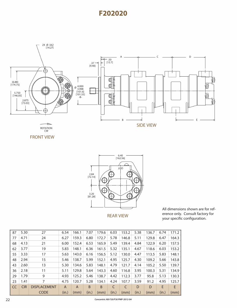
F202020
87776862554843362923CC
171.2164.3157.5153.2148.1143.8139.7134.9130.3125.7
E(mm)
6.546.276.005.835.635.465.305.114.934.75
A(in.)
7.076.806.536.366.165.995.835.645.465.28
B(in.)
6.035.785.495.325.124.954.794.604.424.24
C(in.)
5.385.114.844.674.474.304.143.953.773.59
D(in.)
6.746.476.206.035.835.665.505.315.134.95
E(in.)
272421191715131197
DISPLACEMENTCODE
OUT
2X Ø .562[14.27]
5.750[146.05]
2.875[73.03]
ROTATIONCW
2.84[72.14]
3.20[81.28]
6.40[162.56]
5.304.714.133.773.332.942.602.181.791.41CIR
166.1159.3152.4148.1143.0138.7134.6129.8125.2120.7
A(mm)
179.6172.7165.9161.5156.5152.1148.1143.3138.7134.1
B(mm)
153.2146.8139.4135.1130.0125.7121.7116.8112.3107.7
C(mm)
136.7129.8122.9118.6113.5109.2105.2100.395.891.2
D(mm)
All dimensions shown are for ref-erence only. Consult factory for your specific configuration.
FRONT VIEW
.37[9.40]
.50[12.7]
A C D
B E
SIDE VIEW
REAR VIEW
(6.88)[174.75]
Ø 4.0003.998
[101.6][101.55]
-B-
Concentric AB-F20/F30 PMP-2012-04 23
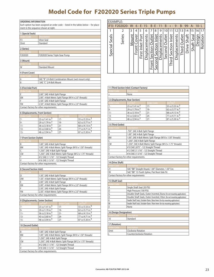
Model Code for F202020 Series Triple Pumps
EXAMPLE:(F3) F202020- W- 6 - E- 15- B -E - 11- B - + - 9 - B- 99- A- 10- L
Spec
ial S
eals
Serie
s
Mou
nt
Fron
t Cov
erFi
rst I
nlet
Por
tD
ispl
acem
ents
Fron
t Sec
tion
Out
let
Seco
nd S
ectio
n In
let
Dis
plac
emen
tsSe
cond
Out
let
Third
Sec
tion
Inle
tD
ispl
acem
ents
Driv
e Sh
aft
Shaf
t Sea
lD
esig
nRo
tatio
n
1 2 3 4 5 6 7 8 9 10 11 12 13 14 15 16 17
Third
Out
let
11 (Third Section Inlet) (Contact Factory)
Order Code Description+ None
12 (Displacements, Rear Section)
Order Code Cm3/In3 Order Code Cm3/In3
7- 23 cc/1.41 in.3 17- 55 cc/3.33 in.3
9- 29 cc/1.79 in.3 19- 62 cc/3.77 in.3
11- 36 cc/2.18 in.3 21- 68 cc/4.13 in.3
13- 43 cc/2.60 in.3 24- 77 cc/4.71 in.3
15- 48 cc/2.94 in.3 27- 87 cc/5.30 in.3
13 (Third Outlet)
Order Code DescriptionA .750”, SAE 4-Bolt Split FlangeB 1.00”, SAE 4-Bolt Split FlangeBM 1.00”, SAE 4-Bolt Metric Split Flange (M10 x 1.50” threads)C 1.250”, SAE 4-Bolt Split FlangeCM 1.250”, SAE 4-Bolt Metric Split Flange (M12 x 1.75” threads)S #10 SAE (.875” - 12) Straight ThreadT #12 SAE (1 1/16” - 12) Straight ThreadV #16 SAE (1 5/16” - 12) Straight ThreadContact factory for other requirements.
14 (Drive Shaft)
Order Code Description21 SAE “BB” Straight Keyed, 1.00” Diameter, 1.50” Ext.99 SAE “BB” 15-Tooth Spline, Flat Root-Side FitContact factory for other requirements
15 (Shaft Seal)
Order Code DescriptionA Single Shaft Seal (30 PSI)D High Pressure (100 PSI)G Double Shaft Seals, Outer Inverted, Buna (for wet mounting applications)H Double Shaft Seals, Outer Inverted, Viton (for wet mounting applications)K Double Shaft Seals, Excluder Outer, Buna Inner (for dry mounting applications)M Double Shaft Seals, Excluder Outer, Viton Inner (for dry mounting applications)X None
16 (Design Designation)
Order Code Description10 Standard
17 (Rotation)
Order Code DescriptionOmit Clockwise RotationL Counterclockwise Rotation
ORDERING INFORMATION
Each option has been assigned an order code -- listed in the tables below -- for place-ment in the sequence shown at right.
1 (Special Seals)
Order Code DescriptionF3 Viton SealOmit Standard
2 (Series)
Order Code DescriptionF202020 F202020 Series Triple Gear Pump
3 (Mount)
Order Code DescriptionW Standard Mount
4 (Front Cover)
Order Code Description6 SAE “B” 2/4-Bolt Combination Mount (wet mount only)8 SAE “C” 2/4-Bolt Mount
5 (First Inlet Port)
Order Code DescriptionE 2.00”, SAE 4-Bolt Split FlangeEM 2.00”, 4-Bolt Metric Split Flange (M14 x 2.0” threads)F 2.50”, SAE 4-Bolt Split FlangeFM 2.50”, 4-Bolt Metric Split Flange (M14 x 2.0” threads)Contact factory for other requirements.
6 (Displacements, Front Section)
Order Code Cm3/In3 Order Code Cm3/In3
7- 23 cc/1.41 in.3 17- 55 cc/3.33 in.3
9- 29 cc/1.79 in.3 19- 62 cc/3.77 in.3
11- 36 cc/2.18 in.3 21- 68 cc/4.13 in.3
13- 43 cc/2.60 in.3 24- 77 cc/4.71 in.3
15- 48 cc/2.94 in.3 27- 87 cc/5.30 in.3
7 (Front Section Outlet)
Order Code DescriptionB 1.00”, SAE 4-Bolt Split FlangeBM 1.00”, SAE 4-Bolt Metric Split Flange (M10 x 1.50” threads)C 1.250”, SAE 4-Bolt Split FlangeCM 1.250”, SAE 4-Bolt Metric Split Flange (M12 x 1.75” threads)T #12 SAE (1 1/16” - 12) Straight ThreadV #16 SAE (1 5/16” - 12) Straight ThreadContact factory for other requirements.
8 (Second Section Inlet)
Order Code DescriptionD 1.50”, SAE 4-Bolt Split FlangeDM 1.50”, 4-Bolt Metric Split Flange (M14 x 2.0” threads)E 2.00”, SAE 4-Bolt Split FlangeEM 2.00”, 4-Bolt Metric Split Flange (M14 x 2.0” threads)F 2.50”, SAE 4-Bolt Split FlangeFM 2.50”, 4-Bolt Metric Split Flange (M14 x 2.0” threads)Contact factory for other requirements.
9 (Displacements, Center Section)
Order Code Cm3/In3 Order Code Cm3/In3
7- 23 cc/1.41 in.3 17- 55 cc/3.33 in.3
9- 29 cc/1.79 in.3 19- 62 cc/3.77 in.3
11- 36 cc/2.18 in.3 21- 68 cc/4.13 in.3
13- 43 cc/2.60 in.3 24- 77 cc/4.71 in.3
15- 48 cc/2.94 in.3 27- 87 cc/5.30 in.3
10 (Second Outlet)
Order Code DescriptionB 1.00”, SAE 4-Bolt Split FlangeBM 1.00”, SAE 4-Bolt Metric Split Flange (M10 x 1.50” threads)C 1.250”, SAE 4-Bolt Split FlangeCM 1.250”, SAE 4-Bolt Metric Split Flange (M12 x 1.75” threads)T #12 SAE (1 1/16” - 12) Straight ThreadV #16 SAE (1 5/16” - 12) Straight ThreadContact factory for other requirements.
Concentric AB-F20/F30 PMP-2012-0424
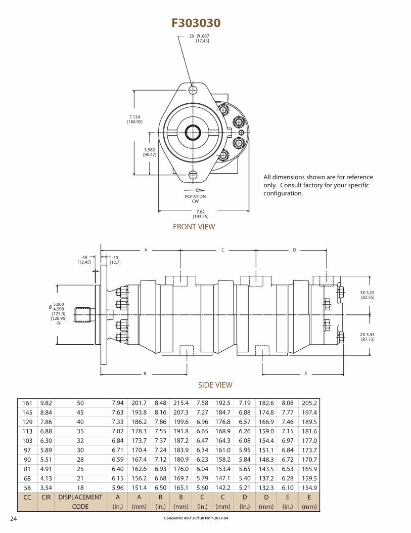
F303030
205.2197.4189.5181.6177.0173.7170.7165.9159.5154.9
E(mm)
7.587.276.966.656.476.346.236.045.795.60
C(in.)
8.087.777.467.156.976.846.726.536.286.10
E(in.)
1611451291131039790816858CC
50454035323028252118
DISPLACEMENTCODE
7.947.637.337.026.846.716.596.406.155.96
A(in.)
8.488.167.867.557.377.247.126.936.686.50
B(in.)
Ø 5.0004.998
[127.0][126.95]
-B-
7.196.886.576.266.085.955.845.655.405.21
D(in.)
9.828.847.866.886.305.895.514.914.133.54CIR
201.7193.8186.2178.3173.7170.4167.4162.6156.2151.4
A(mm)
215.4207.3199.6191.8187.2183.9180.9176.0169.7165.1
B(mm)
192.5184.7176.8168.9164.3161.0158.2153.4147.1142.2
C(mm)
182.6174.8166.9159.0154.4151.1148.3143.5137.2132.3
D(mm)
ROTATIONCW
2X Ø .687[17.45]
7.124[180.95]
3.562[90.47]
7.62[193.55]
All dimensions shown are for reference only. Consult factory for your specific configuration.
FRONT VIEW
.49[12.45]
.50[12.7]
A C D
3X 3.25[82.55]
2X 3.43[87.12]
EB
SIDE VIEW
Concentric AB-F20/F30 PMP-2012-04 25
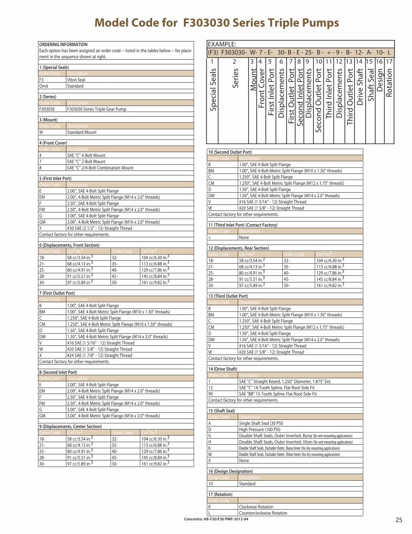
Model Code for F303030 Series Triple Pumps
EXAMPLE:(F3) F303030- W- 7 - E- 30- B - E - 25- B - + - 9 - B- 12- A- 10- L
Spec
ial S
eals
Serie
s
Mou
nt
Fron
t Cov
erFi
rst I
nlet
Por
tD
ispl
acem
ents
Firs
t Out
let
Port
Seco
nd In
let P
ort
Dis
plac
emen
tsSe
cond
Out
let P
ort
Third
Inle
t Por
tD
ispl
acem
ents
Driv
e Sh
aft
Shaf
t Sea
lD
esig
nRo
tatio
n
1 2 3 4 5 6 7 8 9 10 11 12 13 14 15 16 17
Third
Out
let P
ort
10 (Second Outlet Port)
Order Code DescriptionB 1.00”, SAE 4-Bolt Split FlangeBM 1.00”, SAE 4-Bolt Metric Split Flange (M10 x 1.50” threads)C 1.250”, SAE 4-Bolt Split FlangeCM 1.250”, SAE 4-Bolt Metric Split Flange (M12 x 1.75” threads)D 1.50”, SAE 4-Bolt Split FlangeDM 1.50”, SAE 4-Bolt Metric Split Flange (M14 x 2.0” threads)V #16 SAE (1 5/16” - 12) Straight ThreadW #20 SAE (1 5/8” - 12) Straight ThreadContact factory for other requirements.
11 (Third Inlet Port) (Contact Factory)
Order Code Description+ None
12 (Displacements, Rear Section)
Order Code Cm3/In3 Order Code Cm3/In3
18- 58 cc/3.54 in.3 32- 104 cc/6.30 in.3
21- 68 cc/4.13 in.3 35- 113 cc/6.88 in.3
25- 80 cc/4.91 in.3 40- 129 cc/7.86 in.3
28- 91 cc/5.51 in.3 45- 145 cc/8.84 in.3
30- 97 cc/5.89 in.3 50- 161 cc/9.82 in.3
13 (Third Outlet Port)
Order Code DescriptionB 1.00”, SAE 4-Bolt Split FlangeBM 1.00”, SAE 4-Bolt Metric Split Flange (M10 x 1.50” threads)C 1.250”, SAE 4-Bolt Split FlangeCM 1.250”, SAE 4-Bolt Metric Split Flange (M12 x 1.75” threads)D 1.50”, SAE 4-Bolt Split FlangeDM 1.50”, SAE 4-Bolt Metric Split Flange (M14 x 2.0” threads)V #16 SAE (1 5/16” - 12) Straight ThreadW #20 SAE (1 5/8” - 12) Straight ThreadContact factory for other requirements.
14 (Drive Shaft)
Order Code Description1 SAE “C” Straight Keyed, 1.250” Diameter, 1.875” Ext.12 SAE “C” 14-Tooth Spline, Flat Root-Side Fit99 SAE “BB” 15-Tooth Spline, Flat Root-Side FitContact factory for other requirements
15 (Shaft Seal)
Order Code DescriptionA Single Shaft Seal (30 PSI)D High Pressure (100 PSI)G Double Shaft Seals, Outer Inverted, Buna (for wet mounting applications)H Double Shaft Seals, Outer Inverted, Viton (for wet mounting applications)K Double Shaft Seals, Excluder Outer, Buna Inner (for dry mounting applications)M Double Shaft Seals, Excluder Outer, Viton Inner (for dry mounting applications)X None
16 (Design Designation)
Order Code Description10 Standard
17 (Rotation)
Order Code DescriptionR Clockwise RotationL Counterclockwise Rotation
ORDERING INFORMATION
Each option has been assigned an order code -- listed in the tables below -- for place-ment in the sequence shown at right.
1 (Special Seals)
Order Code DescriptionF3 Viton SealOmit Standard
2 (Series)
Order Code DescriptionF303030 F303030 Series Triple Gear Pump
3 (Mount)
Order Code DescriptionW Standard Mount
4 (Front Cover)
Order Code Description4 SAE “C” 4-Bolt Mount7 SAE “C” 2-Bolt Mount 8 SAE “C” 2/4-Bolt Combination Mount
5 (First Inlet Port)
Order Code DescriptionE 2.00”, SAE 4-Bolt Split FlangeEM 2.00”, 4-Bolt Metric Split Flange (M14 x 2.0” threads)F 2.50”, SAE 4-Bolt Split FlangeFM 2.50”, 4-Bolt Metric Split Flange (M14 x 2.0” threads)G 3.00”, SAE 4-Bolt Split FlangeGM 3.00”, 4-Bolt Metric Split Flange (M16 x 2.0” threads)Y #30 SAE (2 1/2” - 12) Straight ThreadContact factory for other requirements.
6 (Displacements, Front Section)
Order Code Cm3/In3 Order Code Cm3/In3
18- 58 cc/3.54 in.3 32- 104 cc/6.30 in.3
21- 68 cc/4.13 in.3 35- 113 cc/6.88 in.3
25- 80 cc/4.91 in.3 40- 129 cc/7.86 in.3
28- 91 cc/5.51 in.3 45- 145 cc/8.84 in.3
30- 97 cc/5.89 in.3 50- 161 cc/9.82 in.3
7 (First Outlet Port)
Order Code DescriptionB 1.00”, SAE 4-Bolt Split FlangeBM 1.00”, SAE 4-Bolt Metric Split Flange (M10 x 1.50” threads)C 1.250”, SAE 4-Bolt Split FlangeCM 1.250”, SAE 4-Bolt Metric Split Flange (M10 x 1.50” threads)D 1.50”, SAE 4-Bolt Split FlangeDM 1.50”, SAE 4-Bolt Metric Split Flange (M14 x 2.0” threads)V #16 SAE (1 5/16” - 12) Straight ThreadW #20 SAE (1 5/8” - 12) Straight ThreadX #24 SAE (1 7/8” - 12) Straight ThreadContact factory for other requirements.
8 (Second Inlet Port)
Order Code DescriptionE 2.00”, SAE 4-Bolt Split FlangeEM 2.00”, 4-Bolt Metric Split Flange (M14 x 2.0” threads)F 2.50”, SAE 4-Bolt Split FlangeFM 2.50”, 4-Bolt Metric Split Flange (M14 x 2.0” threads)G 3.00”, SAE 4-Bolt Split FlangeGM 3.00”, 4-Bolt Metric Split Flange (M16 x 2.0” threads)
9 (Displacements, Center Section)
Order Code Cm3/In3 Order Code Cm3/In3
18- 58 cc/3.54 in.3 32- 104 cc/6.30 in.3
21- 68 cc/4.13 in.3 35- 113 cc/6.88 in.3
25- 80 cc/4.91 in.3 40- 129 cc/7.86 in.3
28- 91 cc/5.51 in.3 45- 145 cc/8.84 in.3
30- 97 cc/5.89 in.3 50- 161 cc/9.82 in.3
Concentric AB-F20/F30 PMP-2012-0426
W900 SECTIONS
F20 SECTIONS
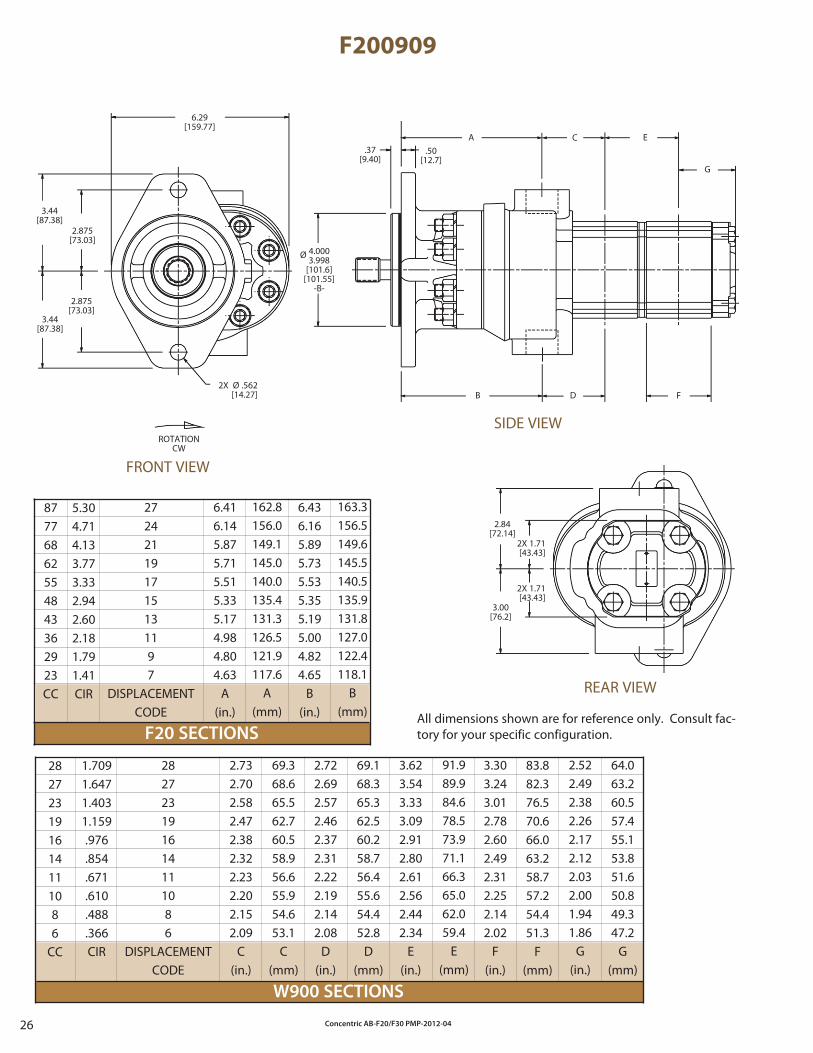
F200909
272421191715131197
DISPLACEMENTCODE
64.063.260.557.455.153.851.650.849.347.2
G(mm)
2.522.492.382.262.172.122.032.001.941.86
G(in.)
69.168.365.362.560.258.756.455.654.452.8
D(mm)
87776862554843362923CC
6.416.145.875.715.515.335.174.984.804.63
A(in.)
6.436.165.895.735.535.355.195.004.824.65
B(in.)
282723191614111086
DISPLACEMENTCODE
2.732.702.582.472.382.322.232.202.152.09
C(in.)
2.722.692.572.462.372.312.222.192.142.08
D(in.)
3.623.543.333.092.912.802.612.562.442.34
E(in.)
3.303.243.012.782.602.492.312.252.142.02
F(in.)
282723191614111086
CC
5.304.714.133.773.332.942.602.181.791.41CIR
162.8156.0149.1145.0140.0135.4131.3126.5121.9117.6
A(mm)
163.3156.5149.6145.5140.5135.9131.8127.0122.4118.1
B(mm)
1.7091.6471.4031.159.976.854.671.610.488.366CIR
69.368.665.562.760.558.956.655.954.653.1
C(mm)
91.989.984.678.573.971.166.365.062.059.4
E(mm)
83.882.376.570.666.063.258.757.254.451.3
F(mm)
.37[9.40]
.50[12.7]
A C E
G
FDB
SIDE VIEWROTATION
CW
6.29[159.77]
3.44[87.38]
2.875[73.03]
3.44[87.38]
2.875[73.03]
2X Ø .562[14.27]
2.84[72.14]
3.00[76.2]
All dimensions shown are for reference only. Consult fac-tory for your specific configuration.
FRONT VIEW
REAR VIEW
2X 1.71[43.43]
2X 1.71[43.43]
Ø 4.0003.998
[101.6][101.55]
-B-
Concentric AB-F20/F30 PMP-2012-04 27
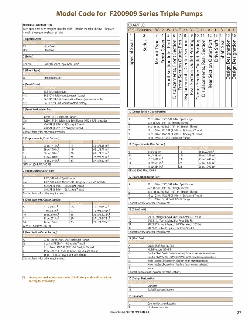
Model Code for F200909 Series Triple Pumps
ORDERING INFORMATION
Each option has been assigned an order code -- listed in the tables below -- for place-ment in the sequence shown at right.
1 (Special Seals)
Order Code DescriptionF3 Viton SealOmit Standard
2 (Series)
Order Code DescriptionF200909 F200909 Series Triple Gear Pump
3 (Mount Type)
Order Code DescriptionW Standard Mount
4 (Front Cover)
Order Code Description2 SAE “B” 2-Bolt Mount4(*) SAE “C” 4-Bolt Mount (contact factory)6 SAE “B” 2/4-Bolt Combination Mount (wet mount only)8(*) SAE “C” 2/4-Bolt Mount (contact factory)
5 (Front Section Inlet Port)
Order Code DescriptionC 1.250”, SAE 4-Bolt Split FlangeCM 1.250”, SAE 4-Bolt Metric Split Flange (M12 x 1.75” threads)V #16 SAE (1 5/16” - 12) Straight ThreadW #20 SAE (1 5/8” - 12) Straight ThreadContact factory for other requirements.
6 (Displacements, Front Section)
Order Code Cm3/In3 Order Code Cm3/In3
7- 23 cc/1.41 in.3 17- 55 cc/3.33 in.3
9- 29 cc/1.79 in.3 19- 62 cc/3.77 in.3
11- 36 cc/2.18 in.3 21- 68 cc/4.13 in.3
13- 43 cc/2.60 in.3 24- 77 cc/4.71 in.3
15- 48 cc/2.94 in.3 27- 87 cc/5.30 in.3
GPM @ 1200 RPM, 100 PSI
7 (Front Section Outlet Port)
Order Code DescriptionB 1.00”, SAE 4-Bolt Split FlangeBM 1.00”, SAE 4-Bolt Metric Split Flange (M10 x 1.50” threads)T #12 SAE (1 1/16” - 12) Straight ThreadV #16 SAE (1 5/16” - 12) Straight ThreadContact factory for other requirements.
8 (Displacements, Center Section)
Order Code Cm3/In3 Order Code Cm3/In3
6- 6 cc/.366 in.3 16- 16 cc/.976 in.3
8- 8 cc/.488 in.3 19- 19 cc/1.159 in.3
10- 10 cc/.610 in.3 23- 23 cc/1.403 in.3
11- 11 cc/.671 in.3 27- 27 cc/1.647 in.3
14- 14 cc/.854 in.3 28- 28 cc/1.709 in.3
GPM @ 1200 RPM, 100 PSI
9 (Rear Section Outlet Porting)
Order Code DescriptionA 23 cc - 28 cc, .750”, SAE 4-Bolt Split FlangeQ 6 cc, #8 SAE (3/4” - 16) Straight ThreadS 8 cc - 16 cc, #10 SAE (7/8” - 14) Straight ThreadT 19 cc - 28 cc, #12 SAE (1 1/16” - 12) Straight ThreadY 16 cc - 19 cc, .5”, SAE 4-Bolt Split FlangeContact factory for other requirements.
EXAMPLE:(F3)- F200909- W- 2 - W- 13- T -23- Y- Q -11- A- 1 - B - 10- L
Des
ign
Des
igna
tion
Spec
ial S
eals
Serie
s
Mou
nt T
ype
Fron
t Cov
erFr
ont S
ectio
n In
let P
ort
Dis
plac
emen
ts, F
ront
Sec
tion
Fron
t Sec
tion
Out
let P
ort
Dis
plac
emen
ts, C
ente
r Sec
tion
Rear
Sec
tion
Out
let P
ortin
gCe
nter
Sec
tion
Out
let P
ortin
gD
ispl
acem
ents
, Rea
r Sec
tion
Rear
Sec
tion
Out
let P
ort
Driv
e Sh
aft
1 2 3 4 5 6 7 8 9 10 11 12 13 14 15 16
Shaf
t Sea
lD
esig
n D
esig
natio
n
10 (Center Section Outlet Porting)
Order Code DescriptionA 23 cc - 28 cc, .750”, SAE 4-Bolt Split FlangeQ 6 cc, #8 SAE (3/4” - 16) Straight ThreadS 8 cc - 16 cc, #10 SAE (7/8” - 14) Straight ThreadT 19 cc - 28 cc, #12 SAE (1 1/16” - 12) Straight ThreadV 19 cc - 28 cc, #16 SAE (1 5/16” - 14) Straight ThreadY 16 cc - 19 cc, .5”, SAE 4-Bolt Split Flange
11 (Displacements, Rear Section)
Order Code Cm3/In3 Order Code Cm3/In3
6- 6 cc/.366 in.3 16- 16 cc/.976 in.3
8- 8 cc/.488 in.3 19- 19 cc/1.159 in.3
10- 10 cc/.610 in.3 23- 23 cc/1.403 in.3
11- 11 cc/.671 in.3 27- 27 cc/1.647 in.3
14- 14 cc/.854 in.3 28- 28 cc/1.709 in.3
GPM @ 1200 RPM, 100 PSI
12 (Rear Section Outlet Port)
Order Code DescriptionA 23 cc - 28 cc, .750”, SAE 4-Bolt Split FlangeQ 6 cc, #8 SAE (3/4” - 16) Straight ThreadS 8 cc - 16 cc, #10 SAE (7/8” - 14) Straight ThreadT 19 cc - 28 cc, #12 SAE (1 1/16” - 12) Straight ThreadY 16 cc - 19 cc, .5”, SAE 4-Bolt Split FlangeContact factory for other requirements.
13 (Drive Shaft)
Order Code Description1 SAE “B” Straight Keyed, .875” Diameter, 1.312” Ext.12 SAE “B” 13-Tooth Spline, Flat Root-Side Fit21 SAE “BB” Straight Keyed, 1.00” Diameter, 1.50” Ext.99 SAE “BB” 15-Tooth Spline, Flat Root-Side FitContact factory for other requirements.
14 (Shaft Seal)
Order Code DescriptionA Single Shaft Seal (30 PSI)D High Pressure (100 PSI)G Double Shaft Seals, Outer Inverted, Buna (for wet mounting applications)H Double Shaft Seals, Outer Inverted, Viton (for wet mounting applications)K Double Shaft Seals, Excluder Outer, Buna Inner (for dry mounting applications)M Double Shaft Seals, Excluder Outer, Viton Inner (for dry mounting applications)X NoneContact Applications Engineer for Valve Options.
15 (Design Designation)
Order Code Description10 Standard11 Sealed Between Sections
16 (Rotation)
Order Code DescriptionL Counterclockwise RotationR Clockwise Rotation
(*) Any option marked with an asterisk (*) indicates you should contact the
factory for availability.
Concentric AB-F20/F30 PMP-2012-0428
F20 SECTIONS
W900 SECTIONS
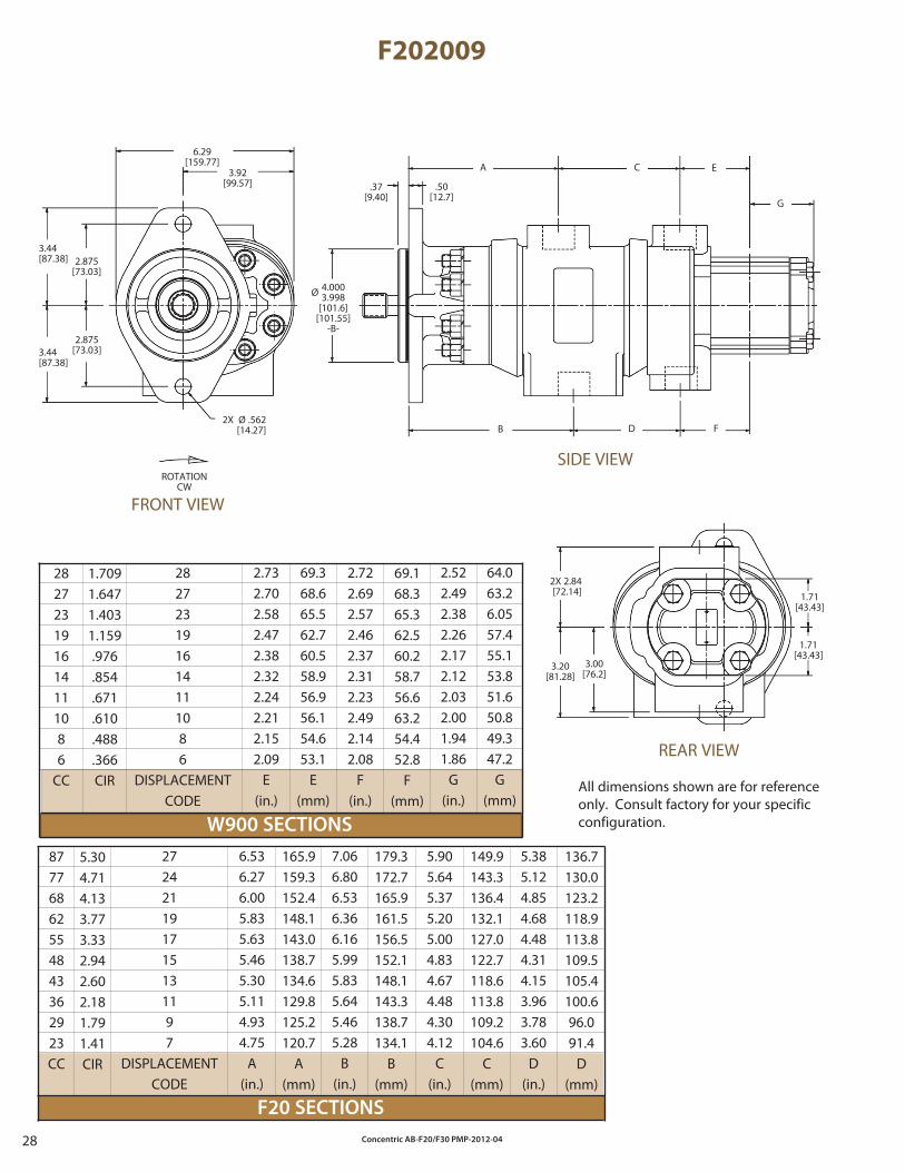
F202009
165.9159.3152.4148.1143.0138.7134.6129.8125.2120.7
A(mm)
282723191614111086
CC
69.368.665.562.760.558.956.956.154.653.1
E(mm)
7.066.806.536.366.165.995.835.645.465.28
B(in.)
87776862554843362923CC
272421191715131197
DISPLACEMENTCODE
6.536.276.005.835.635.465.305.114.934.75
A(in.)
2.732.702.582.472.382.322.242.212.152.09
E(in.)
2.722.692.572.462.372.312.232.492.142.08
F(in.)
2.522.492.382.262.172.122.032.001.941.86
G(in.)
5.905.645.375.205.004.834.674.484.304.12
C(in.)
5.385.124.854.684.484.314.153.963.783.60
D(in.)
5.304.714.133.773.332.942.602.181.791.41CIR
179.3172.7165.9161.5156.5152.1148.1143.3138.7134.1
B(mm)
149.9143.3136.4132.1127.0122.7118.6113.8109.2104.6
C(mm)
136.7130.0123.2118.9113.8109.5105.4100.696.091.4
D(mm)
1.7091.6471.4031.159.976.854.671.610.488.366CIR
69.168.365.362.560.258.756.663.254.452.8
F(mm)
64.063.26.0557.455.153.851.650.849.347.2
G(mm)
282723191614111086
DISPLACEMENTCODE
ROTATIONCW
6.29[159.77]
3.92[99.57]
3.44[87.38] 2.875
[73.03]
3.44[87.38]
2.875[73.03]
2X Ø .562[14.27]
.37[9.40]
.50[12.7]
A C E
G
FDB
2X 2.84[72.14]
3.20[81.28]
3.00[76.2]
All dimensions shown are for reference only. Consult factory for your specific configuration.
FRONT VIEW
SIDE VIEW
REAR VIEW
1.71[43.43]
1.71[43.43]
Ø 4.0003.998
[101.6][101.55]
-B-
Concentric AB-F20/F30 PMP-2012-04 29
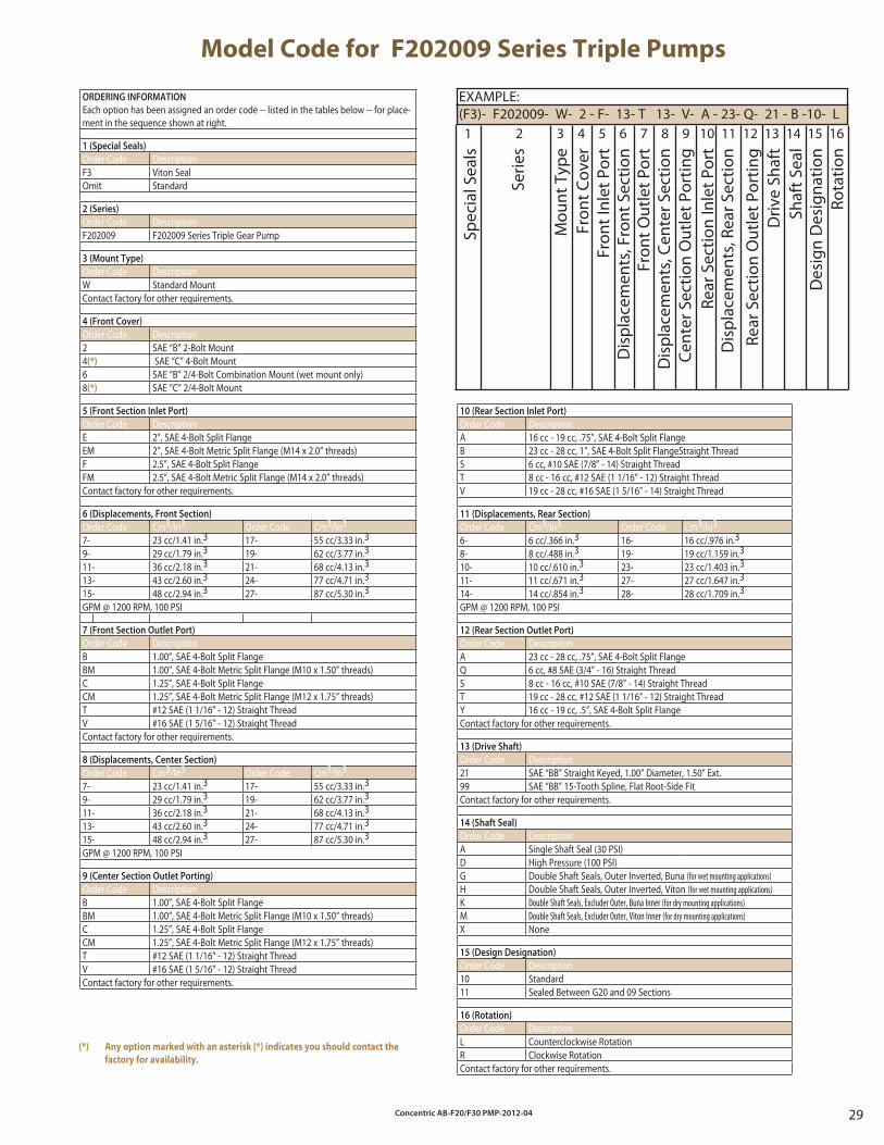
Model Code for F202009 Series Triple Pumps
10 (Rear Section Inlet Port)
Order Code DescriptionA 16 cc - 19 cc, .75”, SAE 4-Bolt Split FlangeB 23 cc - 28 cc, 1”, SAE 4-Bolt Split FlangeStraight ThreadS 6 cc, #10 SAE (7/8” - 14) Straight ThreadT 8 cc - 16 cc, #12 SAE (1 1/16” - 12) Straight ThreadV 19 cc - 28 cc, #16 SAE (1 5/16” - 14) Straight Thread
11 (Displacements, Rear Section)
Order Code Cm3/In3 Order Code Cm3/In3
6- 6 cc/.366 in.3 16- 16 cc/.976 in.3
8- 8 cc/.488 in.3 19- 19 cc/1.159 in.3
10- 10 cc/.610 in.3 23- 23 cc/1.403 in.3
11- 11 cc/.671 in.3 27- 27 cc/1.647 in.3
14- 14 cc/.854 in.3 28- 28 cc/1.709 in.3
GPM @ 1200 RPM, 100 PSI
12 (Rear Section Outlet Port)
Order Code DescriptionA 23 cc - 28 cc, .75”, SAE 4-Bolt Split FlangeQ 6 cc, #8 SAE (3/4” - 16) Straight ThreadS 8 cc - 16 cc, #10 SAE (7/8” - 14) Straight ThreadT 19 cc - 28 cc, #12 SAE (1 1/16” - 12) Straight ThreadY 16 cc - 19 cc, .5”, SAE 4-Bolt Split FlangeContact factory for other requirements.
13 (Drive Shaft)
Order Code Description21 SAE “BB” Straight Keyed, 1.00” Diameter, 1.50” Ext.99 SAE “BB” 15-Tooth Spline, Flat Root-Side FitContact factory for other requirements.
14 (Shaft Seal)
Order Code DescriptionA Single Shaft Seal (30 PSI)D High Pressure (100 PSI)G Double Shaft Seals, Outer Inverted, Buna (for wet mounting applications)H Double Shaft Seals, Outer Inverted, Viton (for wet mounting applications)K Double Shaft Seals, Excluder Outer, Buna Inner (for dry mounting applications)M Double Shaft Seals, Excluder Outer, Viton Inner (for dry mounting applications)X None
15 (Design Designation)
Order Code Description10 Standard11 Sealed Between G20 and 09 Sections
16 (Rotation)
Order Code DescriptionL Counterclockwise RotationR Clockwise RotationContact factory for other requirements.
EXAMPLE:(F3)- F202009- W- 2 - F- 13- T 13- V- A - 23- Q- 21 - B -10- L
Cent
er S
ectio
n O
utle
t Por
ting
Rota
tion
Spec
ial S
eals
Serie
s
Mou
nt T
ype
Fron
t Cov
erFr
ont I
nlet
Por
tD
ispl
acem
ents
, Fro
nt S
ectio
nFr
ont O
utle
t Por
tD
ispl
acem
ents
, Cen
ter S
ectio
n
Rear
Sec
tion
Inle
t Por
tD
ispl
acem
ents
, Rea
r Sec
tion
Rear
Sec
tion
Out
let P
ortin
gD
rive
Shaf
t
1 2 3 4 5 6 7 8 9 10 11 12 13 14 15 16
Shaf
t Sea
lD
esig
n D
esig
natio
n
ORDERING INFORMATION
Each option has been assigned an order code -- listed in the tables below -- for place-ment in the sequence shown at right.
1 (Special Seals)
Order Code DescriptionF3 Viton SealOmit Standard
2 (Series)
Order Code DescriptionF202009 F202009 Series Triple Gear Pump
3 (Mount Type)
Order Code DescriptionW Standard MountContact factory for other requirements.
4 (Front Cover)
Order Code Description2 SAE “B” 2-Bolt Mount4(*) SAE “C” 4-Bolt Mount6 SAE “B” 2/4-Bolt Combination Mount (wet mount only)8(*) SAE “C” 2/4-Bolt Mount
5 (Front Section Inlet Port)
Order Code DescriptionE 2”, SAE 4-Bolt Split FlangeEM 2”, SAE 4-Bolt Metric Split Flange (M14 x 2.0” threads)F 2.5”, SAE 4-Bolt Split FlangeFM 2.5”, SAE 4-Bolt Metric Split Flange (M14 x 2.0” threads)Contact factory for other requirements.
6 (Displacements, Front Section)
Order Code Cm3/In3 Order Code Cm3/In3
7- 23 cc/1.41 in.3 17- 55 cc/3.33 in.3
9- 29 cc/1.79 in.3 19- 62 cc/3.77 in.3
11- 36 cc/2.18 in.3 21- 68 cc/4.13 in.3
13- 43 cc/2.60 in.3 24- 77 cc/4.71 in.3
15- 48 cc/2.94 in.3 27- 87 cc/5.30 in.3
GPM @ 1200 RPM, 100 PSI
7 (Front Section Outlet Port)
Order Code DescriptionB 1.00”, SAE 4-Bolt Split FlangeBM 1.00”, SAE 4-Bolt Metric Split Flange (M10 x 1.50” threads)C 1.25”, SAE 4-Bolt Split FlangeCM 1.25”, SAE 4-Bolt Metric Split Flange (M12 x 1.75” threads)T #12 SAE (1 1/16” - 12) Straight ThreadV #16 SAE (1 5/16” - 12) Straight ThreadContact factory for other requirements.
8 (Displacements, Center Section)
Order Code Cm3/In3 Order Code Cm3/In3
7- 23 cc/1.41 in.3 17- 55 cc/3.33 in.3
9- 29 cc/1.79 in.3 19- 62 cc/3.77 in.3
11- 36 cc/2.18 in.3 21- 68 cc/4.13 in.3
13- 43 cc/2.60 in.3 24- 77 cc/4.71 in.3
15- 48 cc/2.94 in.3 27- 87 cc/5.30 in.3
GPM @ 1200 RPM, 100 PSI
9 (Center Section Outlet Porting)
Order Code DescriptionB 1.00”, SAE 4-Bolt Split FlangeBM 1.00”, SAE 4-Bolt Metric Split Flange (M10 x 1.50” threads)C 1.25”, SAE 4-Bolt Split FlangeCM 1.25”, SAE 4-Bolt Metric Split Flange (M12 x 1.75” threads)T #12 SAE (1 1/16” - 12) Straight ThreadV #16 SAE (1 5/16” - 12) Straight ThreadContact factory for other requirements.
(*) Any option marked with an asterisk (*) indicates you should contact the
factory for availability.
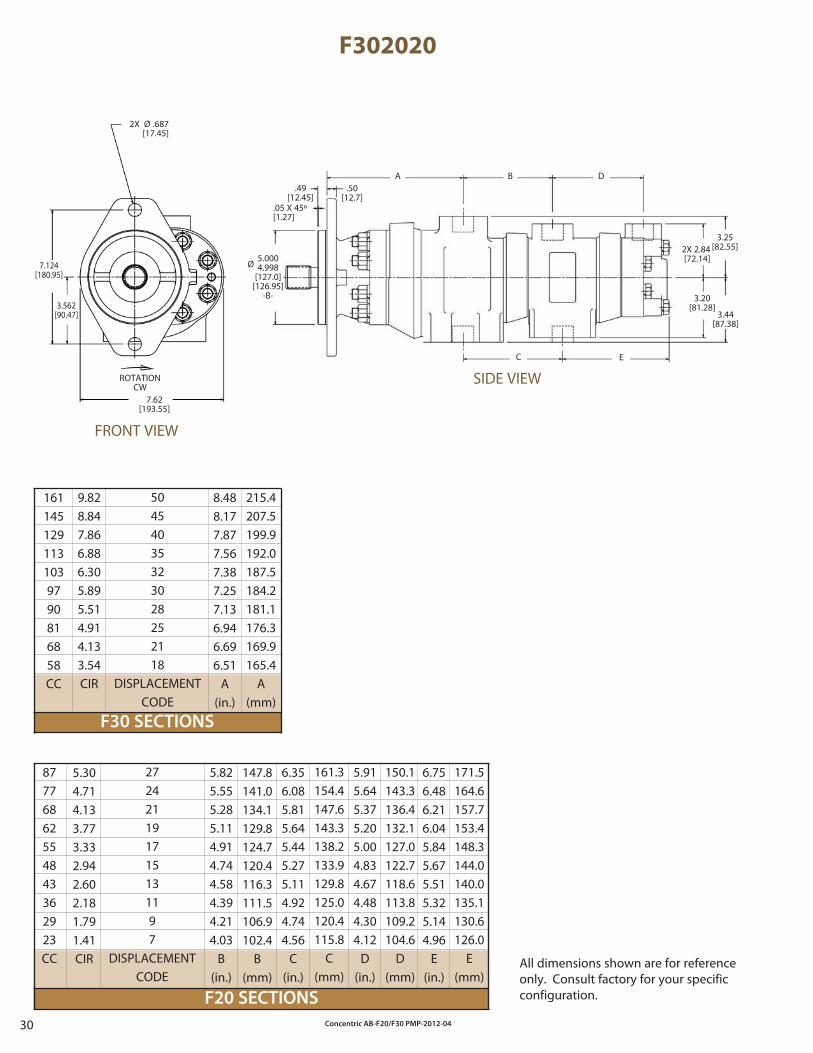
Concentric AB-F20/F30 PMP-2012-0430
F20 SECTIONS
F30 SECTIONS
F302020
272421191715131197
DISPLACEMENTCODE
50454035323028252118
DISPLACEMENTCODE
161.3154.4147.6143.3138.2133.9129.8125.0120.4115.8
C(mm)
87776862554843362923CC
1611451291131039790816858CC
ROTATIONCW
2X Ø .687[17.45]
7.124[180.95]
3.562[90.47]
7.62[193.55]
.49[12.45]
.50[12.7]
.05 X 45º[1.27]
A B D
C E
3.25[82.55]2X 2.84
[72.14]
3.20[81.28]
3.44[87.38]
Ø5.0004.998
[127.0][126.95]
-B-
8.488.177.877.567.387.257.136.946.696.51
A(in.)
5.825.555.285.114.914.744.584.394.214.03
B(in.)
6.356.085.815.645.445.275.114.924.744.56
C(in.)
5.915.645.375.205.004.834.674.484.304.12
D(in.)
6.756.486.216.045.845.675.515.325.144.96
E(in.)
9.828.847.866.886.305.895.514.914.133.54CIR
215.4207.5199.9192.0187.5184.2181.1176.3169.9165.4
A(mm)
5.304.714.133.773.332.942.602.181.791.41CIR
147.8141.0134.1129.8124.7120.4116.3111.5106.9102.4
B(mm)
150.1143.3136.4132.1127.0122.7118.6113.8109.2104.6
D(mm)
171.5164.6157.7153.4148.3144.0140.0135.1130.6126.0
E(mm)
All dimensions shown are for reference only. Consult factory for your specific configuration.
FRONT VIEW
SIDE VIEW
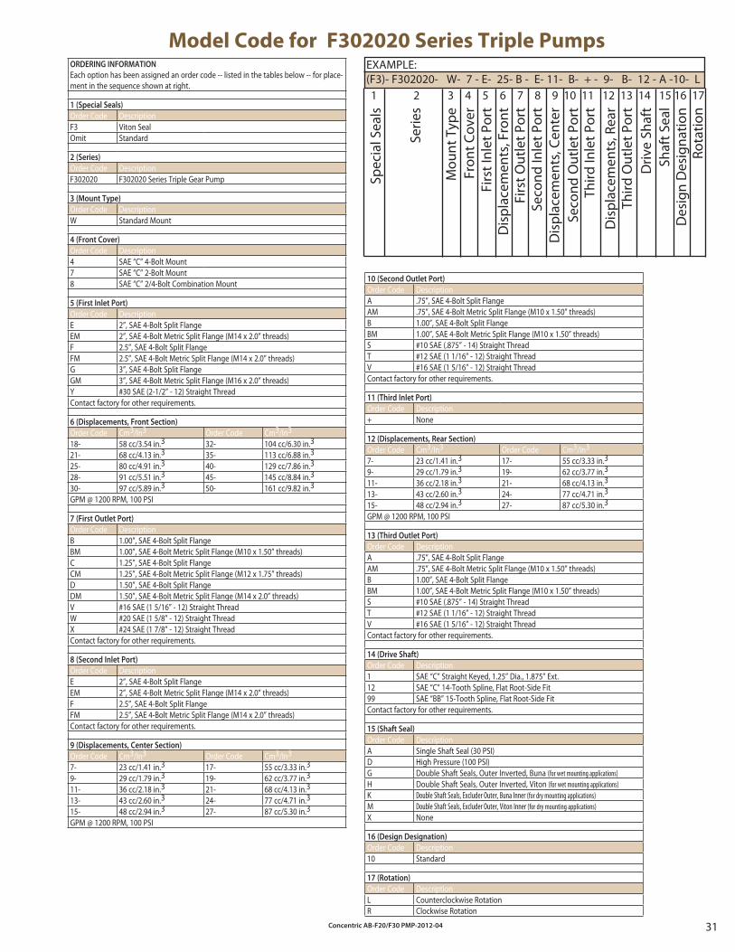
Concentric AB-F20/F30 PMP-2012-04 31
10 (Second Outlet Port)
Order Code DescriptionA .75”, SAE 4-Bolt Split FlangeAM .75”, SAE 4-Bolt Metric Split Flange (M10 x 1.50” threads)B 1.00”, SAE 4-Bolt Split FlangeBM 1.00”, SAE 4-Bolt Metric Split Flange (M10 x 1.50” threads)S #10 SAE (.875” - 14) Straight ThreadT #12 SAE (1 1/16” - 12) Straight ThreadV #16 SAE (1 5/16” - 12) Straight ThreadContact factory for other requirements.
11 (Third Inlet Port)
Order Code Description+ None
12 (Displacements, Rear Section)
Order Code Cm3/In3 Order Code Cm3/In3
7- 23 cc/1.41 in.3 17- 55 cc/3.33 in.3
9- 29 cc/1.79 in.3 19- 62 cc/3.77 in.3
11- 36 cc/2.18 in.3 21- 68 cc/4.13 in.3
13- 43 cc/2.60 in.3 24- 77 cc/4.71 in.3
15- 48 cc/2.94 in.3 27- 87 cc/5.30 in.3
GPM @ 1200 RPM, 100 PSI
13 (Third Outlet Port)
Order Code DescriptionA .75”, SAE 4-Bolt Split FlangeAM .75”, SAE 4-Bolt Metric Split Flange (M10 x 1.50” threads)B 1.00”, SAE 4-Bolt Split FlangeBM 1.00”, SAE 4-Bolt Metric Split Flange (M10 x 1.50” threads)S #10 SAE (.875” - 14) Straight ThreadT #12 SAE (1 1/16” - 12) Straight ThreadV #16 SAE (1 5/16” - 12) Straight ThreadContact factory for other requirements.
14 (Drive Shaft)
Order Code Description1 SAE “C” Straight Keyed, 1.25” Dia., 1.875” Ext.12 SAE “C” 14-Tooth Spline, Flat Root-Side Fit99 SAE “BB” 15-Tooth Spline, Flat Root-Side FitContact factory for other requirements.
15 (Shaft Seal)
Order Code DescriptionA Single Shaft Seal (30 PSI)D High Pressure (100 PSI)G Double Shaft Seals, Outer Inverted, Buna (for wet mounting applications)H Double Shaft Seals, Outer Inverted, Viton (for wet mounting applications)K Double Shaft Seals, Excluder Outer, Buna Inner (for dry mounting applications)M Double Shaft Seals, Excluder Outer, Viton Inner (for dry mounting applications)X None
16 (Design Designation)
Order Code Description10 Standard
17 (Rotation)
Order Code DescriptionL Counterclockwise RotationR Clockwise Rotation
Model Code for F302020 Series Triple PumpsEXAMPLE:(F3)- F302020- W- 7 - E- 25- B - E- 11- B- + - 9- B- 12 - A -10- L
Dis
plac
emen
ts, C
ente
r
Rota
tion
Spec
ial S
eals
Serie
s
Mou
nt T
ype
Fron
t Cov
erFi
rst I
nlet
Por
tD
ispl
acem
ents
, Fro
nt
Firs
t Out
let P
ort
Seco
nd In
let P
ort
Seco
nd O
utle
t Por
tTh
ird In
let P
ort
Dis
plac
emen
ts, R
ear
Driv
e Sh
aft
1 2 3 4 5 6 7 8 9 10 11 12 13 14 15 16 17
Shaf
t Sea
lD
esig
n D
esig
natio
n
Third
Out
let P
ort
ORDERING INFORMATION
Each option has been assigned an order code -- listed in the tables below -- for place-ment in the sequence shown at right.
1 (Special Seals)
Order Code DescriptionF3 Viton SealOmit Standard
2 (Series)
Order Code DescriptionF302020 F302020 Series Triple Gear Pump
3 (Mount Type)
Order Code DescriptionW Standard Mount
4 (Front Cover)
Order Code Description4 SAE “C” 4-Bolt Mount 7 SAE “C” 2-Bolt Mount8 SAE “C” 2/4-Bolt Combination Mount
5 (First Inlet Port)
Order Code DescriptionE 2”, SAE 4-Bolt Split FlangeEM 2”, SAE 4-Bolt Metric Split Flange (M14 x 2.0” threads)F 2.5”, SAE 4-Bolt Split FlangeFM 2.5”, SAE 4-Bolt Metric Split Flange (M14 x 2.0” threads)G 3”, SAE 4-Bolt Split FlangeGM 3”, SAE 4-Bolt Metric Split Flange (M16 x 2.0” threads)Y #30 SAE (2-1/2” - 12) Straight ThreadContact factory for other requirements.
6 (Displacements, Front Section)
Order Code Cm3/In3 Order Code Cm3/In3
18- 58 cc/3.54 in.3 32- 104 cc/6.30 in.3
21- 68 cc/4.13 in.3 35- 113 cc/6.88 in.3
25- 80 cc/4.91 in.3 40- 129 cc/7.86 in.3
28- 91 cc/5.51 in.3 45- 145 cc/8.84 in.3
30- 97 cc/5.89 in.3 50- 161 cc/9.82 in.3
GPM @ 1200 RPM, 100 PSI
7 (First Outlet Port)
Order Code DescriptionB 1.00”, SAE 4-Bolt Split FlangeBM 1.00”, SAE 4-Bolt Metric Split Flange (M10 x 1.50” threads)C 1.25”, SAE 4-Bolt Split FlangeCM 1.25”, SAE 4-Bolt Metric Split Flange (M12 x 1.75” threads)D 1.50”, SAE 4-Bolt Split FlangeDM 1.50”, SAE 4-Bolt Metric Split Flange (M14 x 2.0” threads)V #16 SAE (1 5/16” - 12) Straight ThreadW #20 SAE (1 5/8” - 12) Straight ThreadX #24 SAE (1 7/8” - 12) Straight ThreadContact factory for other requirements.
8 (Second Inlet Port)
Order Code DescriptionE 2”, SAE 4-Bolt Split FlangeEM 2”, SAE 4-Bolt Metric Split Flange (M14 x 2.0” threads)F 2.5”, SAE 4-Bolt Split FlangeFM 2.5”, SAE 4-Bolt Metric Split Flange (M14 x 2.0” threads)Contact factory for other requirements.
9 (Displacements, Center Section)
Order Code Cm3/In3 Order Code Cm3/In3
7- 23 cc/1.41 in.3 17- 55 cc/3.33 in.3
9- 29 cc/1.79 in.3 19- 62 cc/3.77 in.3
11- 36 cc/2.18 in.3 21- 68 cc/4.13 in.3
13- 43 cc/2.60 in.3 24- 77 cc/4.71 in.3
15- 48 cc/2.94 in.3 27- 87 cc/5.30 in.3
GPM @ 1200 RPM, 100 PSI
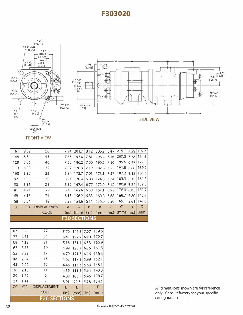
Concentric AB-F20/F30 PMP-2012-0432
F303020
F30 SECTIONS
F20 SECTIONS
272421191715131197
DISPLACEMENTCODE
50454035323028252118
DISPLACEMENTCODE
144.8137.9131.1126.7121.7117.3113.3111.5103.999.3
E(mm)
8.127.817.507.197.016.886.776.586.336.14
B(in.)
8.478.167.867.557.377.247.126.936.686.50
C(in.)
7.597.286.976.666.486.356.246.055.805.61
D(in.)
87776862554843362923CC
1611451291131039790816858CC
ROTATIONCW
7.58[192.53]
2X Ø .640[16.26] 3.27
[83.06]2X 2.65[67.31]
2.254[57.25]
2.254[57.25]
2.254[57.25]
2.254[57.25]
2X R .62[15.75]
4.508[114.50]
2X 6.40[162.56]
2X R 3.20[81.28]
.49[12.45]
.50[12.7]
A B E
FDC
2X 3.25[82.55]2.84
[72.14]
2X 3.43[87.12]
.05 X 45º[1.27]
Ø5.0004.998
[127.0][126.95]
-B-
7.947.637.337.026.846.716.596.406.155.97
A(in.)
5.705.435.164.994.794.624.464.394.093.91
E(in.)
7.076.806.536.366.165.995.835.645.465.28
F(in.)
9.828.847.866.886.305.895.514.914.133.54CIR
201.7193.8186.2178.3173.7170.4167.4162.6156.2151.6
A(mm)
206.2198.4190.5182.6178.1174.8172.0167.1160.8156.0
B(mm)
215.1207.3199.6191.8187.2183.9180.8176.0169.7165.1
C(mm)
192.8184.9177.0169.2164.6161.3158.5153.7147.3142.5
D(mm)
5.304.714.133.773.332.942.602.181.791.41CIR
179.6172.7165.9161.5156.5152.1148.1143.3138.7134.1
F(mm)
All dimensions shown are for reference only. Consult factory for your specific configuration.
FRONT VIEW
SIDE VIEW
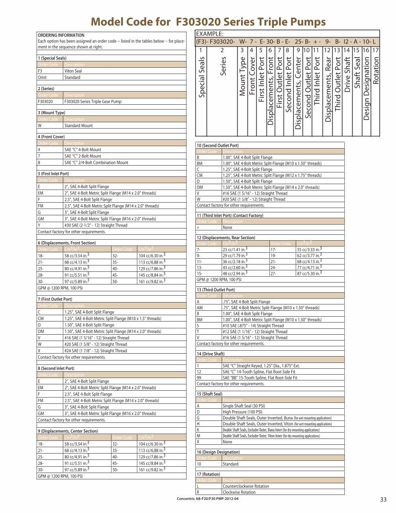
Concentric AB-F20/F30 PMP-2012-04 33
ORDERING INFORMATION
Each option has been assigned an order code -- listed in the tables below -- for place-ment in the sequence shown at right.
1 (Special Seals)
Order Code DescriptionF3 Viton SealOmit Standard
2 (Series)
Order Code DescriptionF303020 F303020 Series Triple Gear Pump
3 (Mount Type)
Order Code DescriptionW Standard Mount
4 (Front Cover)
Order Code Description4 SAE “C” 4-Bolt Mount 7 SAE “C” 2-Bolt Mount8 SAE “C” 2/4-Bolt Combination Mount
5 (First Inlet Port)
Order Code DescriptionE 2”, SAE 4-Bolt Split FlangeEM 2”, SAE 4-Bolt Metric Split Flange (M14 x 2.0” threads)F 2.5”, SAE 4-Bolt Split FlangeFM 2.5”, SAE 4-Bolt Metric Split Flange (M14 x 2.0” threads)G 3”, SAE 4-Bolt Split FlangeGM 3”, SAE 4-Bolt Metric Split Flange (M16 x 2.0” threads)Y #30 SAE (2-1/2” - 12) Straight ThreadContact factory for other requirements.
6 (Displacements, Front Section)
Order Code Cm3/In3 Order Code Cm3/In3
18- 58 cc/3.54 in.3 32- 104 cc/6.30 in.3
21- 68 cc/4.13 in.3 35- 113 cc/6.88 in.3
25- 80 cc/4.91 in.3 40- 129 cc/7.86 in.3
28- 91 cc/5.51 in.3 45- 145 cc/8.84 in.3
30- 97 cc/5.89 in.3 50- 161 cc/9.82 in.3
GPM @ 1200 RPM, 100 PSI
7 (First Outlet Port)
Order Code DescriptionC 1.25”, SAE 4-Bolt Split FlangeCM 1.25”, SAE 4-Bolt Metric Split Flange (M10 x 1.5” threads)D 1.50”, SAE 4-Bolt Split FlangeDM 1.50”, SAE 4-Bolt Metric Split Flange (M14 x 2.0” threads)V #16 SAE (1 5/16” - 12) Straight ThreadW #20 SAE (1 5/8” - 12) Straight ThreadX #24 SAE (1 7/8” - 12) Straight ThreadContact factory for other requirements.
8 (Second Inlet Port)
Order Code DescriptionE 2”, SAE 4-Bolt Split FlangeEM 2”, SAE 4-Bolt Metric Split Flange (M14 x 2.0” threads)F 2.5”, SAE 4-Bolt Split FlangeFM 2.5”, SAE 4-Bolt Metric Split Flange (M14 x 2.0” threads)G 3”, SAE 4-Bolt Split FlangeGM 3”, SAE 4-Bolt Metric Split Flange (M16 x 2.0” threads)Contact factory for other requirements.
9 (Displacements, Center Section)
Order Code Cm3/In3 Order Code Cm3/In3
18- 58 cc/3.54 in.3 32- 104 cc/6.30 in.3
21- 68 cc/4.13 in.3 35- 113 cc/6.88 in.3
25- 80 cc/4.91 in.3 40- 129 cc/7.86 in.3
28- 91 cc/5.51 in.3 45- 145 cc/8.84 in.3
30- 97 cc/5.89 in.3 50- 161 cc/9.82 in.3
GPM @ 1200 RPM, 100 PSI
Model Code for F303020 Series Triple PumpsEXAMPLE:(F3)- F303020- W- 7 - E- 30- B - E- 25- B- + - 9- B- I2 - A - 10- L
Dis
plac
emen
ts, C
ente
r
Rota
tion
Spec
ial S
eals
Serie
s
Mou
nt T
ype
Fron
t Cov
erFi
rst I
nlet
Por
tD
ispl
acem
ents
, Fro
nt
Firs
t Out
let P
ort
Seco
nd In
let P
ort
Seco
nd O
utle
t Por
tTh
ird In
let P
ort
Dis
plac
emen
ts, R
ear
Driv
e Sh
aft
1 2 3 4 5 6 7 8 9 10 11 12 13 14 15 16 17
Shaf
t Sea
lD
esig
n D
esig
natio
n
Third
Out
let P
ort
10 (Second Outlet Port)
Order Code DescriptionB 1.00”, SAE 4-Bolt Split FlangeBM 1.00”, SAE 4-Bolt Metric Split Flange (M10 x 1.50” threads)C 1.25”, SAE 4-Bolt Split FlangeCM 1.25”, SAE 4-Bolt Metric Split Flange (M12 x 1.75” threads)D 1.50”, SAE 4-Bolt Split FlangeDM 1.50”, SAE 4-Bolt Metric Split Flange (M14 x 2.0” threads)V #16 SAE (1 5/16” - 12) Straight ThreadW #20 SAE (1 5/8” - 12) Straight ThreadContact factory for other requirements.
11 (Third Inlet Port) (Contact Factory)
Order Code Description+ None
12 (Displacements, Rear Section)
Order Code Cm3/In3 Order Code Cm3/In3
7- 23 cc/1.41 in.3 17- 55 cc/3.33 in.3
9- 29 cc/1.79 in.3 19- 62 cc/3.77 in.3
11- 36 cc/2.18 in.3 21- 68 cc/4.13 in.3
13- 43 cc/2.60 in.3 24- 77 cc/4.71 in.3
15- 48 cc/2.94 in.3 27- 87 cc/5.30 in.3
GPM @ 1200 RPM, 100 PSI
13 (Third Outlet Port)
Order Code DescriptionA .75”, SAE 4-Bolt Split FlangeAM .75”, SAE 4-Bolt Metric Split Flange (M10 x 1.50” threads)B 1.00”, SAE 4-Bolt Split FlangeBM 1.00”, SAE 4-Bolt Metric Split Flange (M10 x 1.50” threads)S #10 SAE (.875” - 14) Straight ThreadT #12 SAE (1 1/16” - 12) Straight ThreadV #16 SAE (1 5/16” - 12) Straight ThreadContact factory for other requirements.
14 (Drive Shaft)
Order Code Description1 SAE “C” Straight Keyed, 1.25” Dia., 1.875” Ext.12 SAE “C” 14-Tooth Spline, Flat Root-Side Fit99 SAE “BB” 15-Tooth Spline, Flat Root-Side FitContact factory for other requirements.
15 (Shaft Seal)
Order Code DescriptionA Single Shaft Seal (30 PSI)D High Pressure (100 PSI)G Double Shaft Seals, Outer Inverted, Buna (for wet mounting applications)H Double Shaft Seals, Outer Inverted, Viton (for wet mounting applications)K Double Shaft Seals, Excluder Outer, Buna Inner (for dry mounting applications)M Double Shaft Seals, Excluder Outer, Viton Inner (for dry mounting applications)X None
16 (Design Designation)
Order Code Description10 Standard
17 (Rotation)
Order Code DescriptionL Counterclockwise RotationR Clockwise Rotation
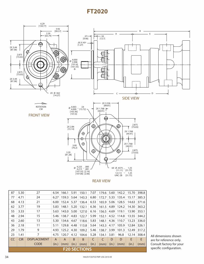
Concentric AB-F20/F30 PMP-2012-0434
F20 SECTIONS
FT2020
272421191715131197
DISPLACEMENTCODE
2X 2.84[72.14]
3.20[81.28]
3.00[76.2]
2X 1.768[44.91]
2X 1.768[44.91]
2X 3.536[89.81]
2.875[73.03]
2.875[73.03]
2X 1.768[44.91]
REAR VIEW
HALEX-F20/F30 PMP-USA-2010-09
7.076.806.536.366.165.995.835.645.465.28
C(in.)
179.6172.7165.9161.5156.5152.1148.1143.3138.7134.1
C(mm)
150.1143.3136.4132.1127.0122.7118.6113.8109.2104.6
B(mm)
15.7015.1714.6314.3013.9013.5513.2312.8412.4912.14
E(in.)
1/2-13 UNC-2B
87776862554843362923CC
ROTATIONCW
6.29[159.77]
3.92[99.57]
2.59[65.79]
2.875[73.03]
2X 3.44[87.38]
2.875[73.03]
2X 3.44[87.38]
2X Ø .562[14.27]
6X Ø .4375[11.11]
1.25[31.75]
1.25[31.75]
Ø 4.0034.000
[102.36][101.6]
.54[13.72]
6.546.276.005.835.635.465.305.114.934.75
A(in.)
5.915.645.375.205.004.834.674.484.304.12
B(in.)
5.605.335.064.894.694.524.364.173.993.81
D(in.)
5.304.714.133.773.332.942.602.181.791.41CIR
166.1159.3152.4148.1143.0138.7134.6129.8125.2120.7
A(mm)
142.2135.4128.5124.2119.1114.8110.7105.9101.396.8
D(mm)
398.8385.3371.6363.2353.1344.2336.0326.1317.2308.4
E(mm)
.37[9.40]
.50[12.7]
.05 X 45º[1.27]
AB
E
DC
All dimensions shown are for reference only. Consult factory for your specific configuration.
FRONT VIEW
SIDE VIEW
Ø 4.2254.215
[107.32][107.06]
.085
.081[2.16][2.06]
Ø4.0003.998
[101.6][101.55]
-B-
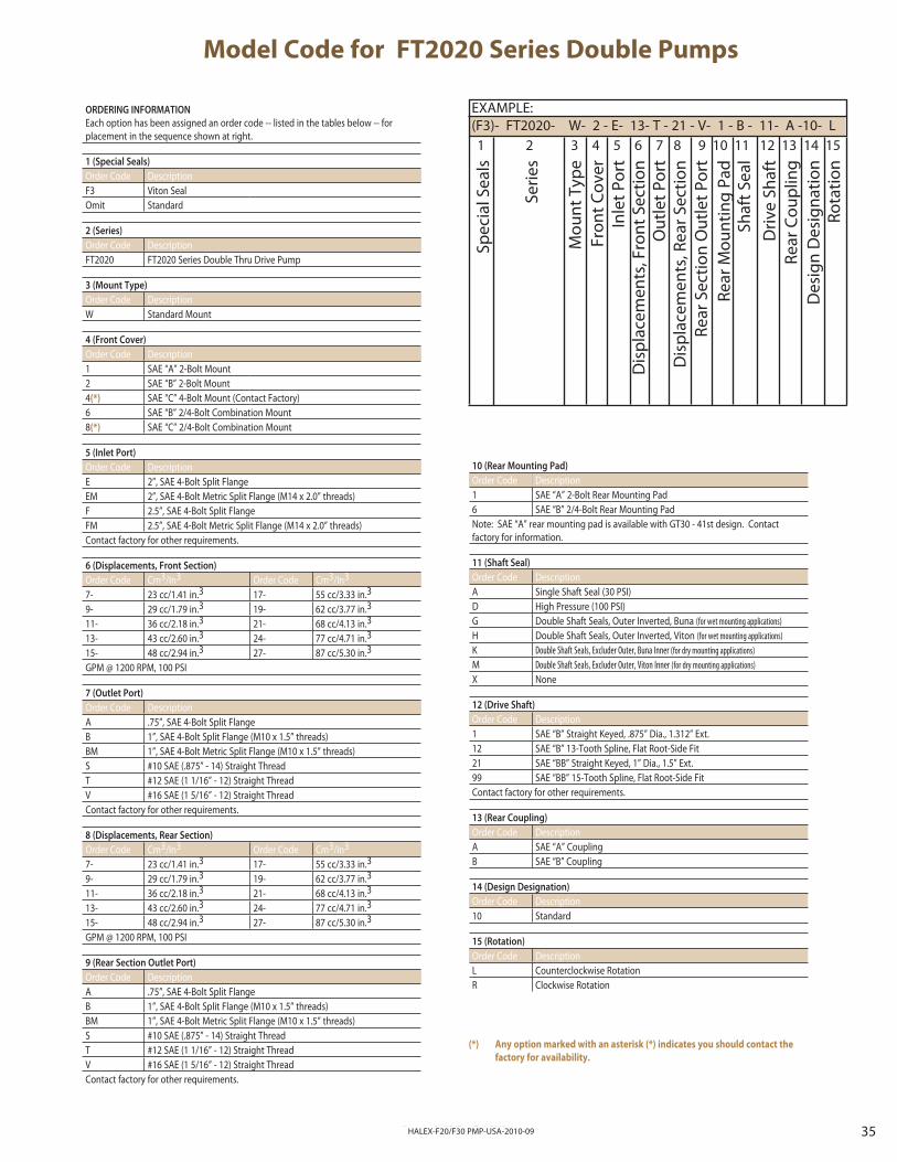
Concentric AB-F20/F30 PMP-2012-04 35HALEX-F20/F30 PMP-USA-2010-09
10 (Rear Mounting Pad)
Order Code Description1 SAE “A” 2-Bolt Rear Mounting Pad6 SAE “B” 2/4-Bolt Rear Mounting PadNote: SAE “A” rear mounting pad is available with GT30 - 41st design. Contactfactory for information.
11 (Shaft Seal)
Order Code DescriptionA Single Shaft Seal (30 PSI)D High Pressure (100 PSI)G Double Shaft Seals, Outer Inverted, Buna (for wet mounting applications)H Double Shaft Seals, Outer Inverted, Viton (for wet mounting applications)K Double Shaft Seals, Excluder Outer, Buna Inner (for dry mounting applications)M Double Shaft Seals, Excluder Outer, Viton Inner (for dry mounting applications)X None
12 (Drive Shaft)
Order Code Description1 SAE “B” Straight Keyed, .875” Dia., 1.312” Ext.12 SAE “B” 13-Tooth Spline, Flat Root-Side Fit21 SAE “BB” Straight Keyed, 1” Dia., 1.5” Ext.99 SAE “BB” 15-Tooth Spline, Flat Root-Side FitContact factory for other requirements.
13 (Rear Coupling)
Order Code DescriptionA SAE “A” CouplingB SAE “B” Coupling
14 (Design Designation)
Order Code Description10 Standard
15 (Rotation)
Order Code DescriptionL Counterclockwise RotationR Clockwise Rotation
Model Code for FT2020 Series Double Pumps
EXAMPLE:(F3)- FT2020- W- 2 - E- 13- T - 21 - V- 1 - B - 11- A -10- L
Rear
Sec
tion
Out
let P
ort
Spec
ial S
eals
Serie
s
Mou
nt T
ype
Fron
t Cov
erIn
let P
ort
Dis
plac
emen
ts, F
ront
Sec
tion
Out
let P
ort
Dis
plac
emen
ts, R
ear S
ectio
n
Rear
Mou
ntin
g Pa
dSh
aft S
eal
Driv
e Sh
aft
Rear
Cou
plin
g
1 2 3 4 5 6 7 8 9 10 11 12 13 14 15
Des
ign
Des
igna
tion
Rota
tion
ORDERING INFORMATION
Each option has been assigned an order code -- listed in the tables below -- for placement in the sequence shown at right.
1 (Special Seals)
Order Code DescriptionF3 Viton SealOmit Standard
2 (Series)
Order Code DescriptionFT2020 FT2020 Series Double Thru Drive Pump
3 (Mount Type)
Order Code DescriptionW Standard Mount
4 (Front Cover)
Order Code Description1 SAE “A” 2-Bolt Mount2 SAE “B” 2-Bolt Mount4(*) SAE “C” 4-Bolt Mount (Contact Factory)6 SAE “B” 2/4-Bolt Combination Mount8(*) SAE “C” 2/4-Bolt Combination Mount
5 (Inlet Port)
Order Code DescriptionE 2”, SAE 4-Bolt Split FlangeEM 2”, SAE 4-Bolt Metric Split Flange (M14 x 2.0” threads)F 2.5”, SAE 4-Bolt Split FlangeFM 2.5”, SAE 4-Bolt Metric Split Flange (M14 x 2.0” threads)Contact factory for other requirements.
6 (Displacements, Front Section)
Order Code Cm3/In3 Order Code Cm3/In3
7- 23 cc/1.41 in.3 17- 55 cc/3.33 in.3
9- 29 cc/1.79 in.3 19- 62 cc/3.77 in.3
11- 36 cc/2.18 in.3 21- 68 cc/4.13 in.3
13- 43 cc/2.60 in.3 24- 77 cc/4.71 in.3
15- 48 cc/2.94 in.3 27- 87 cc/5.30 in.3
GPM @ 1200 RPM, 100 PSI
7 (Outlet Port)
Order Code DescriptionA .75”, SAE 4-Bolt Split FlangeB 1”, SAE 4-Bolt Split Flange (M10 x 1.5” threads)BM 1”, SAE 4-Bolt Metric Split Flange (M10 x 1.5” threads)S #10 SAE (.875” - 14) Straight ThreadT #12 SAE (1 1/16” - 12) Straight ThreadV #16 SAE (1 5/16” - 12) Straight ThreadContact factory for other requirements.
8 (Displacements, Rear Section)
Order Code Cm3/In3 Order Code Cm3/In3
7- 23 cc/1.41 in.3 17- 55 cc/3.33 in.3
9- 29 cc/1.79 in.3 19- 62 cc/3.77 in.3
11- 36 cc/2.18 in.3 21- 68 cc/4.13 in.3
13- 43 cc/2.60 in.3 24- 77 cc/4.71 in.3
15- 48 cc/2.94 in.3 27- 87 cc/5.30 in.3
GPM @ 1200 RPM, 100 PSI
9 (Rear Section Outlet Port)
Order Code DescriptionA .75”, SAE 4-Bolt Split FlangeB 1”, SAE 4-Bolt Split Flange (M10 x 1.5” threads)BM 1”, SAE 4-Bolt Metric Split Flange (M10 x 1.5” threads)S #10 SAE (.875” - 14) Straight ThreadT #12 SAE (1 1/16” - 12) Straight ThreadV #16 SAE (1 5/16” - 12) Straight ThreadContact factory for other requirements.
(*) Any option marked with an asterisk (*) indicates you should contact the
factory for availability.
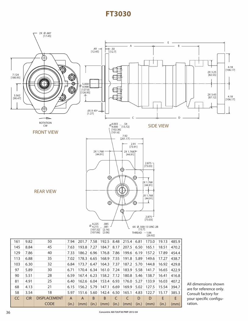
Concentric AB-F20/F30 PMP-2012-0436
FT3030
50454035323028252118
DISPLACEMENTCODE
192.5184.7176.8168.9164.3161.0158.2153.4147.1142.4
B(mm)
19.1318.5117.8917.2716.9216.6516.4116.0315.5415.17
E(in.)
1611451291131039790816858CC
6X Ø .500-13 UNC-2B
1.06THREAD
Ø5.0004.998
[127.0][126.95]
-B-
Ø4.0034.000[102.36][101.6]
.54[13.72]
Ø4.2254.215
[107.32][107.06]
.085
.081[2.16][2.06]
[12.7]
[26.92]
7.947.637.337.026.846.716.596.406.155.97
A(in.)
7.587.276.966.656.476.346.236.045.795.60
B(in.)
8.488.177.867.557.377.247.126.936.696.50
C(in.)
6.816.506.195.895.705.585.465.275.024.83
D(in.)
9.828.847.866.886.305.895.514.914.133.54CIR
201.7193.8186.2178.3173.7170.4167.4162.6156.2151.6
A(mm)
215.4207.5199.6191.8187.2183.9180.8176.0169.9165.1
C(mm)
173.0165.1157.2149.6144.8141.7138.7133.9127.5122.7
D(mm)
485.9470.2454.4438.7429.8422.9416.8407.2394.7385.3
E(mm)
All dimensions shown are for reference only. Consult factory for your specific configu-ration.
ROTATIONCW
2X Ø .687[17.45]
7.124[180.95]
3.562[90.47]
FRONT VIEW
2X 1.768[44.91]
7.92[201.17]
2.91[73.91]
2X 1.768[44.91]
2.875[73.03]
2.875[73.03]
REAR VIEW
2X 1.768[44.91]
2X 1.768[44.91]
2X 3.43[87.12]
2X 3.25[82.55]
.49[12.45]
.50[12.7]
A BE
4.18[106.17]
4.18[106.17]
DC
.05 X 45º[1.27]
SIDE VIEW
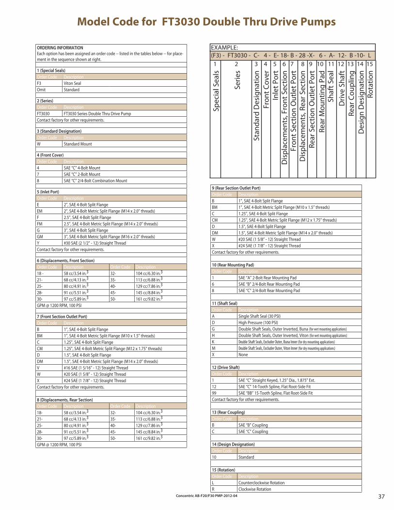
Concentric AB-F20/F30 PMP-2012-04 37
ORDERING INFORMATION
Each option has been assigned an order code -- listed in the tables below -- for place-ment in the sequence shown at right.
1 (Special Seals)
Order Code DescriptionF3 Viton SealOmit Standard
2 (Series)
Order Code DescriptionFT3030 FT3030 Series Double Thru Drive PumpContact factory for other requirements.
3 (Standard Designation)
Order Code DescriptionW Standard Mount
4 (Front Cover)
Order Code Description4 SAE “C” 4-Bolt Mount7 SAE “C” 2-Bolt Mount8 SAE “C” 2/4-Bolt Combination Mount
5 (Inlet Port)
Order Code DescriptionE 2”, SAE 4-Bolt Split FlangeEM 2”, SAE 4-Bolt Metric Split Flange (M14 x 2.0” threads)F 2.5”, SAE 4-Bolt Split FlangeFM 2.5”, SAE 4-Bolt Metric Split Flange (M14 x 2.0” threads)G 3”, SAE 4-Bolt Split FlangeGM 3”, SAE 4-Bolt Metric Split Flange (M16 x 2.0” threads)Y #30 SAE (2 1/2” - 12) Straight ThreadContact factory for other requirements.
6 (Displacements, Front Section)
Order Code Description Order Code Description18 - 58 cc/3.54 in.3 32- 104 cc/6.30 in.3
21- 68 cc/4.13 in.3 35- 113 cc/6.88 in.3
25- 80 cc/4.91 in.3 40- 129 cc/7.86 in.3
28- 91 cc/5.51 in.3 45- 145 cc/8.84 in.3
30- 97 cc/5.89 in.3 50- 161 cc/9.82 in.3
GPM @ 1200 RPM, 100 PSI
7 (Front Section Outlet Port)
Order Code DescriptionB 1”, SAE 4-Bolt Split Flange BM 1”, SAE 4-Bolt Metric Split Flange (M10 x 1.5” threads)C 1.25”, SAE 4-Bolt Split Flange CM 1.25”, SAE 4-Bolt Metric Split Flange (M12 x 1.75” threads)D 1.5”, SAE 4-Bolt Split Flange DM 1.5”, SAE 4-Bolt Metric Split Flange (M14 x 2.0” threads)V #16 SAE (1 5/16” - 12) Straight ThreadW #20 SAE (1 5/8” - 12) Straight ThreadX #24 SAE (1 7/8” - 12) Straight ThreadContact factory for other requirements.
8 (Displacements, Rear Section)
Order Code Description Order Code Description18- 58 cc/3.54 in.3 32- 104 cc/6.30 in.3
21- 68 cc/4.13 in.3 35- 113 cc/6.88 in.3
25- 80 cc/4.91 in.3 40- 129 cc/7.86 in.3
28- 91 cc/5.51 in.3 45- 145 cc/8.84 in.3
30- 97 cc/5.89 in.3 50- 161 cc/9.82 in.3
GPM @ 1200 RPM, 100 PSI
Model Code for FT3030 Double Thru Drive Pumps
EXAMPLE:(F3) - FT3030 - C- 4 - E- 18- B - 28 -X- 6 - A- 12- B -10- L
Rear
Sec
tion
Out
let P
ort
Spec
ial S
eals
Serie
s
Stan
dard
Des
igna
tion
Fron
t Cov
erIn
let P
ort
Dis
plac
emen
ts, F
ront
Sec
tion
Fron
t Sec
tion
Out
let P
ort
Dis
plac
emen
ts, R
ear S
ectio
n
Rear
Mou
ntin
g Pa
dSh
aft S
eal
Driv
e Sh
aft
Rear
Cou
plin
g
1 2 3 4 5 6 7 8 9 10 11 12 13 14 15
Des
ign
Des
igna
tion
Rota
tion
9 (Rear Section Outlet Port)
Order Code DescriptionB 1”, SAE 4-Bolt Split Flange BM 1”, SAE 4-Bolt Metric Split Flange (M10 x 1.5” threads)C 1.25”, SAE 4-Bolt Split Flange CM 1.25”, SAE 4-Bolt Metric Split Flange (M12 x 1.75” threads)D 1.5”, SAE 4-Bolt Split Flange DM 1.5”, SAE 4-Bolt Metric Split Flange (M14 x 2.0” threads)W #20 SAE (1 5/8” - 12) Straight ThreadX #24 SAE (1 7/8” - 12) Straight ThreadContact factory for other requirements.
10 (Rear Mounting Pad)
Order Code Description1 SAE “A” 2-Bolt Rear Mounting Pad6 SAE “B” 2/4-Bolt Rear Mounting Pad8 SAE “C” 2/4-Bolt Rear Mounting Pad
11 (Shaft Seal)
Order Code DescriptionA Single Shaft Seal (30 PSI)D High Pressure (100 PSI)G Double Shaft Seals, Outer Inverted, Buna (for wet mounting applications)H Double Shaft Seals, Outer Inverted, Viton (for wet mounting applications)K Double Shaft Seals, Excluder Outer, Buna Inner (for dry mounting applications)M Double Shaft Seals, Excluder Outer, Viton Inner (for dry mounting applications)X None
12 (Drive Shaft)
Order Code Description1 SAE “C” Straight Keyed, 1.25” Dia., 1.875” Ext.12 SAE “C” 14-Tooth Spline, Flat Root-Side Fit99 SAE “BB” 15-Tooth Spline, Flat Root-Side FitContact factory for other requirements.
13 (Rear Coupling)
Order Code DescriptionB SAE “B” CouplingC SAE “C” Coupling
14 (Design Designation)
Order Code Description10 Standard
15 (Rotation)
Order Code DescriptionL Counterclockwise RotationR Clockwise Rotation
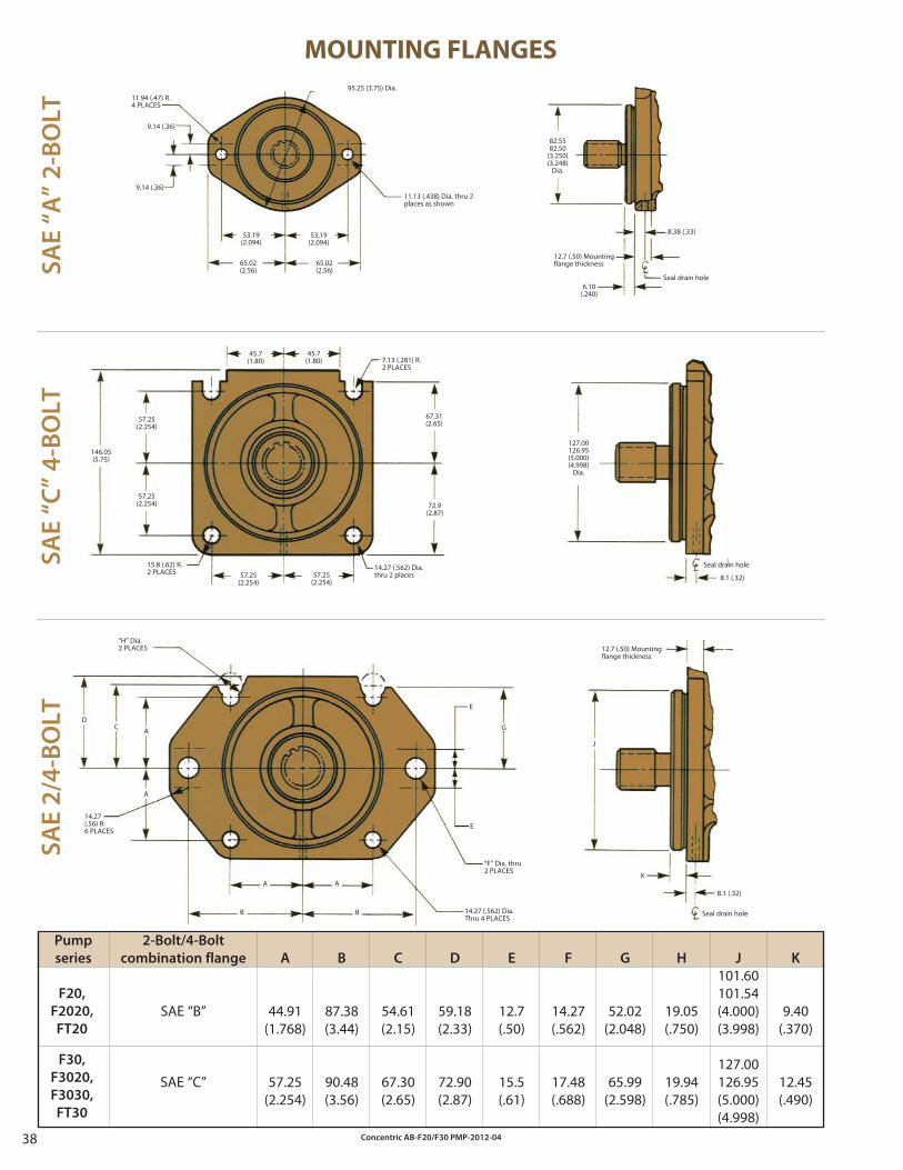
Concentric AB-F20/F30 PMP-2012-0438
Pump
series
G20,
G2020,
GT20
G30,
G3020,
G3030,
GT30
SA
E 2
/4-B
OL
T
K
9.40(.370)
12.45(.490)
A
44.91(1.768)
57.25(2.254)
B
87.38(3.44)
90.48(3.56)
C
54.61(2.15)
67.30(2.65)
D
59.18(2.33)
72.90(2.87)
E
12.7(.50)
15.5(.61)
F
14.27(.562)
17.48(.688)
G
52.02(2.048)
65.99(2.598)
H
19.05(.750)
19.94(.785)
J
101.60101.54(4.000)(3.998)
127.00126.95(5.000)(4.998)
F20,
F2020,
FT20
F30,
F3020,
F3030,
FT30
MOUNTING FLANGES
11.94 (.47) R.4 PLACES
9.14 (.36)
9.14 (.36)
95.25 (3.75) Dia.
11.13 (.438) Dia. thru 2 places as shown
53.19(2.094)
53.19(2.094)
65.02(2.56)
65.02(2.56)
82.5582.50
(3.250)(3.248)
Dia.
12.7 (.50) Mountingflange thickness
6.10(.240)
8.38 (.33)
Seal drain hole
12.7 (.50) Mountingflange thickness
8.1 (.32)
Seal drain hole
J
K
“H” Dia.2 PLACES
14.27(.56) R.6 PLACES
“F” Dia. thru2 PLACES
14.27 (.562) Dia.Thru 4 PLACES
127.00126.95(5.000)(4.998)
Dia.
8.1 (.32)
Seal drain hole
45.7(1.80)
45.7(1.80)
57.25(2.254)
57.25(2.254)
146.05(5.75)
67.31(2.65)
57.25(2.254) 72.9
(2.87)
14.27 (.562) Dia. thru 2 places
7.13 (.281) R.2 PLACES
15.8 (.62) R.2 PLACES 57.25
(2.254)
DC A
A
A A
B B
E
E
G
SA
E “
A”
2-B
OL
TS
AE
“C
” 4
-BO
LT
2-Bolt/4-Bolt
combination flange
SAE “B”
SAE “C”
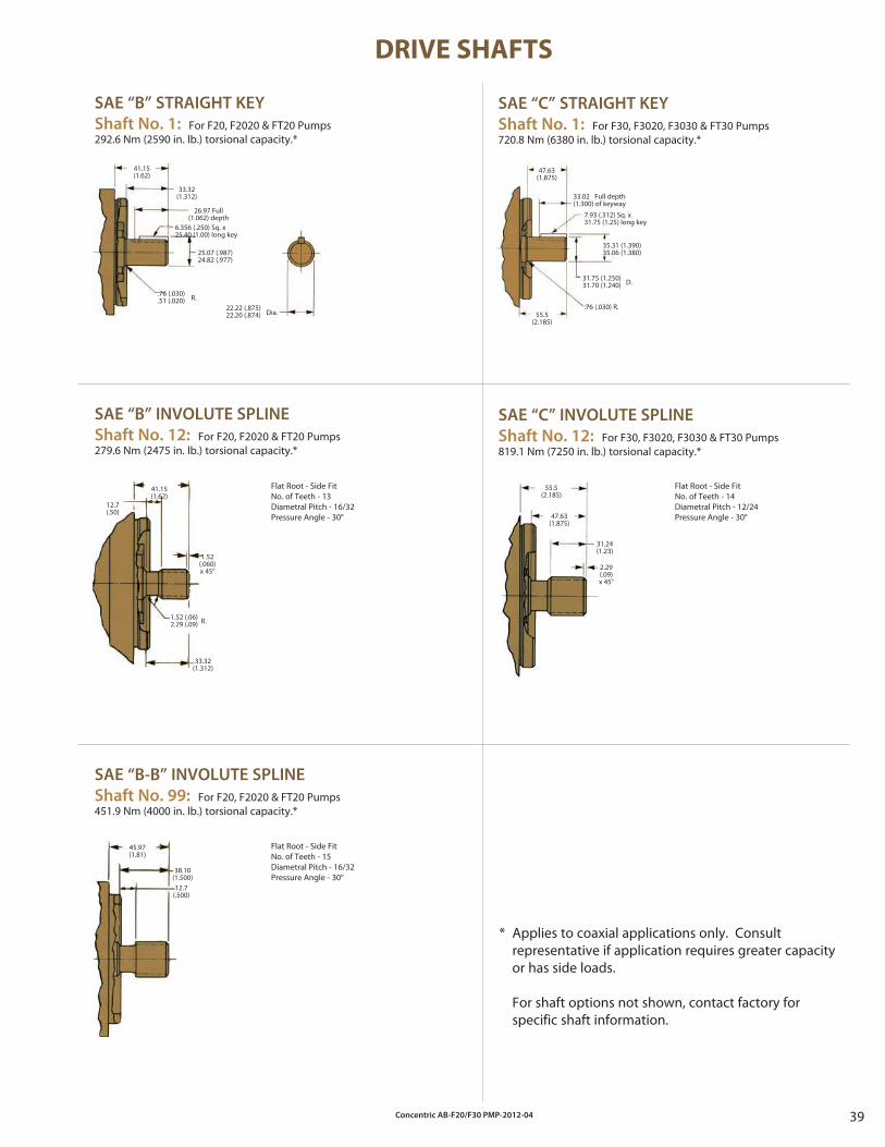
Concentric AB-F20/F30 PMP-2012-04 39
DRIVE SHAFTS
SAE “B” STRAIGHT KEY
Shaft No. 1: For F20, F2020 & FT20 Pumps292.6 Nm (2590 in. lb.) torsional capacity.*
SAE “C” STRAIGHT KEY
Shaft No. 1: For F30, F3020, F3030 & FT30 Pumps720.8 Nm (6380 in. lb.) torsional capacity.*
SAE “B” INVOLUTE SPLINE
Shaft No. 12: For F20, F2020 & FT20 Pumps279.6 Nm (2475 in. lb.) torsional capacity.*
SAE “C” INVOLUTE SPLINE
Shaft No. 12: For F30, F3020, F3030 & FT30 Pumps819.1 Nm (7250 in. lb.) torsional capacity.*
SAE “B-B” INVOLUTE SPLINE
Shaft No. 99: For F20, F2020 & FT20 Pumps451.9 Nm (4000 in. lb.) torsional capacity.*
* Applies to coaxial applications only. Consult representative if application requires greater capacity or has side loads.
For shaft options not shown, contact factory for specific shaft information.
Flat Root - Side FitNo. of Teeth - 13Diametral Pitch - 16/32Pressure Angle - 30°
Flat Root - Side FitNo. of Teeth - 14Diametral Pitch - 12/24Pressure Angle - 30°
Flat Root - Side FitNo. of Teeth - 15Diametral Pitch - 16/32Pressure Angle - 30°
22.22 (.875)22.20 (.874) Dia.
31.75 (1.250)31.70 (1.240) D.
1.52 (.06)2.29 (.09) R.
41.15(1.62)
33.32(1.312)
26.97 Full(1.062) depth
6.356 (.250) Sq. x25.40 (1.00) long key
25.07 (.987)24.82 (.977)
.76 (.030)
.51 (.020) R.
47.63(1.875)
33.02 Full depth(1.300) of keyway
7.93 (.312) Sq. x31.75 (1.25) long key
35.31 (1.390)35.06 (1.380)
.76 (.030) R.55.5
(2.185)
55.5(2.185)
47.63(1.875)
31.24(1.23)
2.29(.09)x 45°
41.15(1.62)
12.7(.50)
1.52(.060)x 45°
33.32(1.312)
45.97(1.81)
38.10(1.500)12.7
(.500)
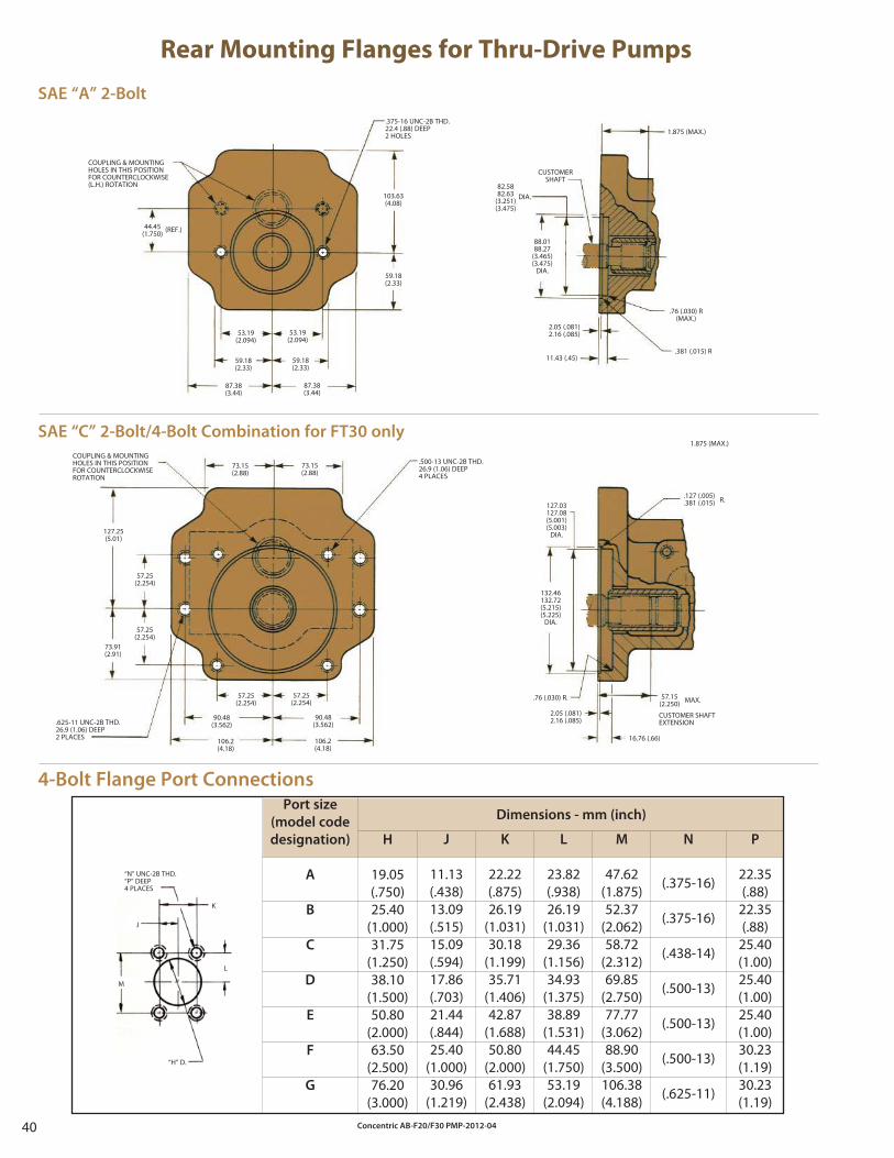
Concentric AB-F20/F30 PMP-2012-0440
Dimensions - mm (inch)
Rear Mounting Flanges for Thru-Drive Pumps
SAE “A” 2-Bolt
SAE “C” 2-Bolt/4-Bolt Combination for FT30 only
.375-16 UNC-2B THD.22.4 (.88) DEEP2 HOLES
COUPLING & MOUNTINGHOLES IN THIS POSITIONFOR COUNTERCLOCKWISE(L.H.) ROTATION
44.45(1.750) (REF.)
53.19(2.094)
59.18(2.33)
87.38(3.44)
53.19(2.094)
59.18(2.33)
87.38(3.44)
59.18(2.33)
103.63(4.08)
82.5882.63
(3.251)(3.475)
DIA.
88.0188.27
(3.465)(3.475)
DIA.
2.05 (.081)2.16 (.085)
11.43 (.45).381 (.015) R
.76 (.030) R(MAX.)
1.875 (MAX.)
CUSTOMERSHAFT
.500-13 UNC-2B THD.26.9 (1.06) DEEP4 PLACES
COUPLING & MOUNTINGHOLES IN THIS POSITIONFOR COUNTERCLOCKWISEROTATION
.625-11 UNC-2B THD.26.9 (1.06) DEEP2 PLACES
73.15(2.88)
73.15(2.88)
127.25(5.01)
73.91(2.91)
57.25(2.254)
57.25(2.254)
57.25(2.254)
57.25(2.254)
90.48(3.562)
90.48(3.562)
106.2(4.18)
106.2(4.18)
127.03127.08(5.001)(5.003)
DIA.
132.46132.72(5.215)(5.225)
DIA.
2.05 (.081)2.16 (.085)
.76 (.030) R.
1.875 (MAX.)
16.76 (.66)
.127 (.005)
.381 (.015) R.
57.15(2.250) MAX.
CUSTOMER SHAFTEXTENSION
4-Bolt Flange Port Connections
Port size
(model code
designation)
A
B
C
D
E
F
G
H
19.05(.750)25.40
(1.000)31.75
(1.250)38.10
(1.500)50.80
(2.000)63.50
(2.500)76.20
(3.000)
J
11.13(.438)13.09(.515)15.09(.594)17.86(.703)21.44(.844)25.40
(1.000)30.96
(1.219)
K
22.22(.875)26.19
(1.031)30.18
(1.199)35.71
(1.406)42.87
(1.688)50.80
(2.000)61.93
(2.438)
L
23.82(.938)26.19
(1.031)29.36
(1.156)34.93
(1.375)38.89
(1.531)44.45
(1.750)53.19
(2.094)
M
47.62(1.875)52.37
(2.062)58.72
(2.312)69.85
(2.750)77.77
(3.062)88.90
(3.500)106.38(4.188)
N
(.375-16)
(.375-16)
(.438-14)
(.500-13)
(.500-13)
(.500-13)
(.625-11)
P
22.35(.88)
22.35(.88)
25.40(1.00)25.40(1.00)25.40(1.00)30.23(1.19)30.23(1.19)
“N” UNC-2B THD.“P” DEEP4 PLACES
J
M
“H” D.
L
K
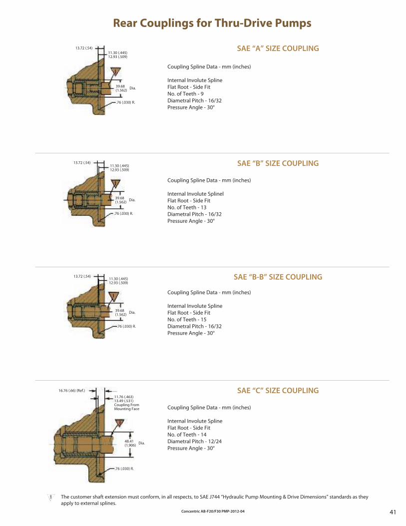
Concentric AB-F20/F30 PMP-2012-04 41
Rear Couplings for Thru-Drive Pumps
Coupling Spline Data - mm (inches)
Internal Involute Spline Flat Root - Side FitNo. of Teeth - 9Diametral Pitch - 16/32Pressure Angle - 30°
Coupling Spline Data - mm (inches)
Internal Involute SplinelFlat Root - Side FitNo. of Teeth - 13Diametral Pitch - 16/32Pressure Angle - 30°
Coupling Spline Data - mm (inches)
Internal Involute Spline Flat Root - Side FitNo. of Teeth - 15Diametral Pitch - 16/32Pressure Angle - 30°
Coupling Spline Data - mm (inches)
Internal Involute Spline Flat Root - Side FitNo. of Teeth - 14Diametral Pitch - 12/24Pressure Angle - 30°
The customer shaft extension must conform, in all respects, to SAE J744 “Hydraulic Pump Mounting & Drive Dimensions” standards as they apply to external splines.
13.72 (.54)11.30 (.445)12.93 (.509)
39.68(1.562) Dia.
.76 (.030) R.
13.72 (.54)11.30 (.445)12.93 (.509)
39.68(1.562) Dia.
.76 (.030) R.
13.72 (.54)11.30 (.445)12.93 (.509)
39.68(1.562) Dia.
.76 (.030) R.
16.76 (.66) (Ref.)
11.76 (.463)13.49 (.531)Coupling FromMounting Face
48.41(1.906) Dia.
.76 (.030) R.
SAE “A” SIZE COUPLING
SAE “B” SIZE COUPLING
SAE “B-B” SIZE COUPLING
SAE “C” SIZE COUPLING
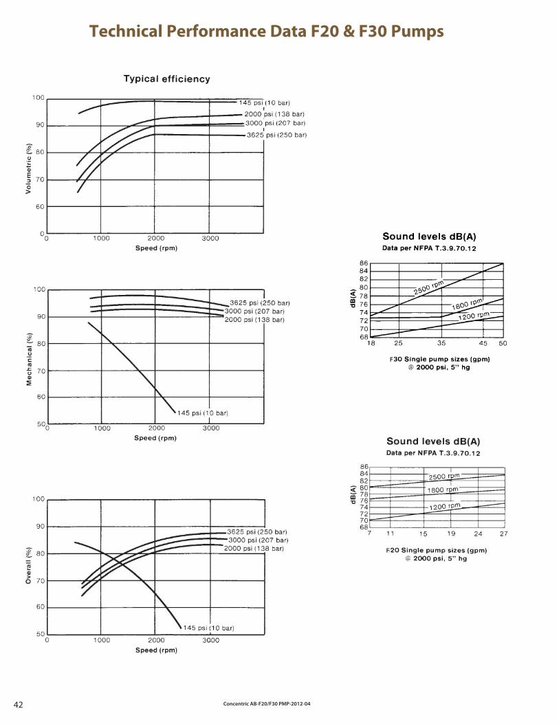
Concentric AB-F20/F30 PMP-2012-0442
Technical Performance Data F20 & F30 Pumps
F
F
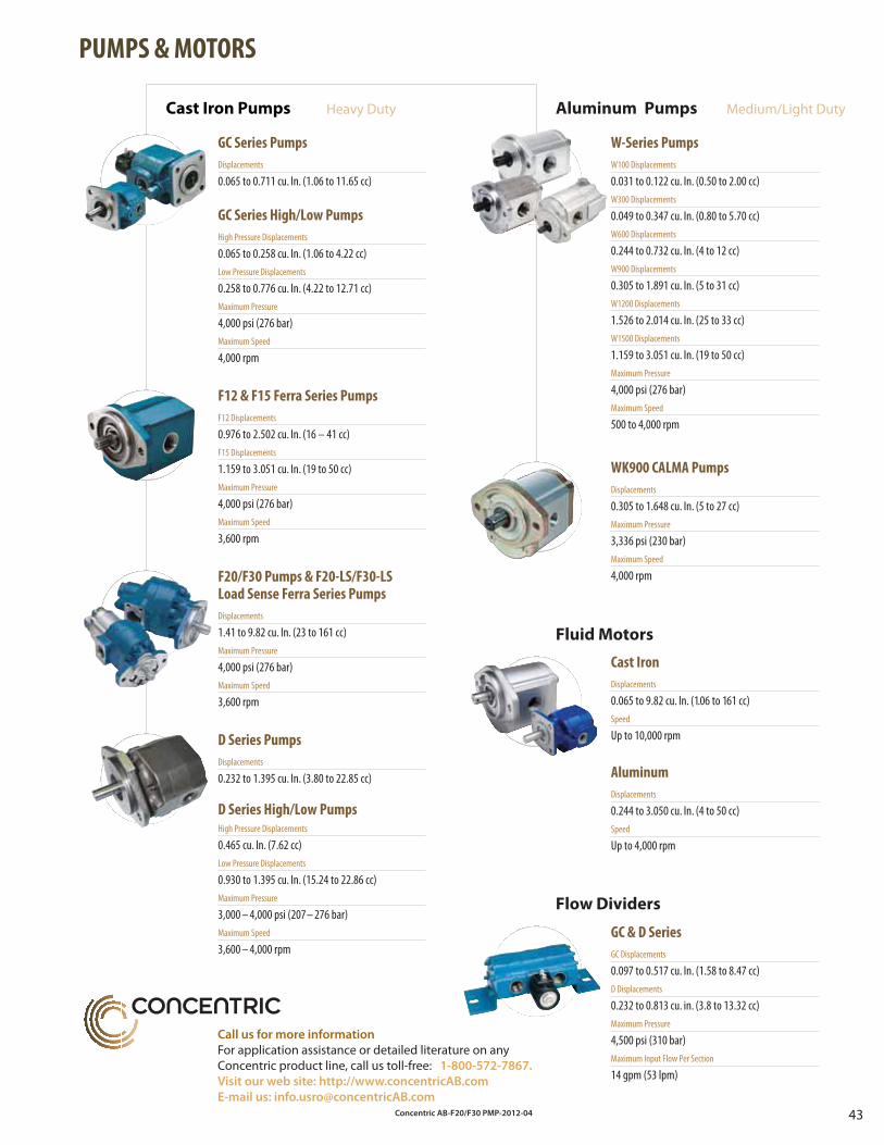
Concentric AB-F20/F30 PMP-2012-04 43
Cast Iron Pumps Heavy Duty
GC Series Pumps
Displacements
0.065 to 0.711 cu. In. (1.06 to 11.65 cc)
GC Series High/Low Pumps
High Pressure Displacements
0.065 to 0.258 cu. In. (1.06 to 4.22 cc)Low Pressure Displacements
0.258 to 0.776 cu. In. (4.22 to 12.71 cc)Maximum Pressure
4,000 psi (276 bar)Maximum Speed
4,000 rpm
W-Series Pumps
W100 Displacements
0.031 to 0.122 cu. In. (0.50 to 2.00 cc)W300 Displacements
0.049 to 0.347 cu. In. (0.80 to 5.70 cc)W600 Displacements
0.244 to 0.732 cu. In. (4 to 12 cc)W900 Displacements
0.305 to 1.891 cu. In. (5 to 31 cc)W1200 Displacements
1.526 to 2.014 cu. In. (25 to 33 cc)W1500 Displacements
1.159 to 3.051 cu. In. (19 to 50 cc)Maximum Pressure
4,000 psi (276 bar)Maximum Speed
500 to 4,000 rpm
D Series Pumps
Displacements
0.232 to 1.395 cu. In. (3.80 to 22.85 cc)
D Series High/Low PumpsHigh Pressure Displacements
0.465 cu. In. (7.62 cc)Low Pressure Displacements
0.930 to 1.395 cu. In. (15.24 to 22.86 cc)Maximum Pressure
3,000 – 4,000 psi (207– 276 bar)Maximum Speed
3,600 – 4,000 rpm
WK900 CALMA Pumps
Displacements
0.305 to 1.648 cu. In. (5 to 27 cc)Maximum Pressure
3,336 psi (230 bar)Maximum Speed
4,000 rpm
F12 & F15 Ferra Series Pumps
F12 Displacements
0.976 to 2.502 cu. In. (16 – 41 cc)F15 Displacements
1.159 to 3.051 cu. In. (19 to 50 cc)Maximum Pressure
4,000 psi (276 bar)Maximum Speed
3,600 rpm
Cast Iron
Displacements
0.065 to 9.82 cu. In. (1.06 to 161 cc)Speed
Up to 10,000 rpm
Aluminum
Displacements
0.244 to 3.050 cu. In. (4 to 50 cc)Speed
Up to 4,000 rpm
Flow Dividers
Fluid Motors
GC & D Series
GC Displacements
0.097 to 0.517 cu. In. (1.58 to 8.47 cc)D Displacements
0.232 to 0.813 cu. in. (3.8 to 13.32 cc)Maximum Pressure
4,500 psi (310 bar)Maximum Input Flow Per Section
14 gpm (53 lpm)
Aluminum Pumps Medium/Light Duty
F20/F30 Pumps & F20-LS/F30-LSLoad Sense Ferra Series Pumps
Displacements
1.41 to 9.82 cu. In. (23 to 161 cc)Maximum Pressure
4,000 psi (276 bar)Maximum Speed
3,600 rpm
PUMPS & MOTORS
Call us for more information
For application assistance or detailed literature on anyConcentric product line, call us toll-free: 1-800-572-7867.
Visit our web site: http://www.concentricAB.com
E-mail us: [email protected]
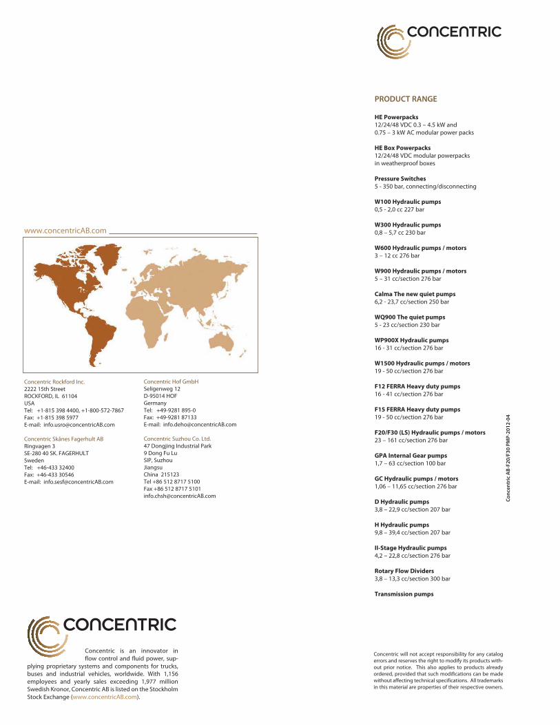
Concentric is an innovator in flow control and fluid power, sup-plying proprietary systems and components for trucks, buses and industrial vehicles, worldwide. With 1,156 employees and yearly sales exceeding 1,977 million Swedish Kronor, Concentric AB is listed on the Stockholm Stock Exchange (www.concentricAB.com).
Co
nce
ntr
ic A
B-F
20
/F3
0 P
MP
-20
12
-04
Concentric will not accept responsibility for any catalog errors and reserves the right to modify its products with-out prior notice. This also applies to products already ordered, provided that such modifications can be made without affecting technical specifications. All trademarks in this material are properties of their respective owners.
PRODUCT RANGE
HE Powerpacks
12/24/48 VDC 0.3 – 4.5 kW and 0.75 – 3 kW AC modular power packs
HE Box Powerpacks
12/24/48 VDC modular powerpacks in weatherproof boxes
Pressure Switches
5 - 350 bar, connecting/disconnecting
W100 Hydraulic pumps
0,5 - 2,0 cc 227 bar
W300 Hydraulic pumps
0,8 – 5,7 cc 230 bar
W600 Hydraulic pumps / motors
3 – 12 cc 276 bar
W900 Hydraulic pumps / motors
5 – 31 cc/section 276 bar
Calma The new quiet pumps
6,2 - 23,7 cc/section 250 bar
WQ900 The quiet pumps
5 - 23 cc/section 230 bar
WP900X Hydraulic pumps
16 - 31 cc/section 276 bar
W1500 Hydraulic pumps / motors
19 - 50 cc/section 276 bar
F12 FERRA Heavy duty pumps
16 - 41 cc/section 276 bar
F15 FERRA Heavy duty pumps
19 - 50 cc/section 276 bar
F20/F30 (LS) Hydraulic pumps / motors
23 – 161 cc/section 276 bar
GPA Internal Gear pumps
1,7 – 63 cc/section 100 bar
GC Hydraulic pumps / motors
1,06 – 11,65 cc/section 276 bar
D Hydraulic pumps
3,8 – 22,9 cc/section 207 bar
H Hydraulic pumps
9,8 – 39,4 cc/section 207 bar
II-Stage Hydraulic pumps
4,2 – 22,8 cc/section 276 bar
Rotary Flow Dividers
3,8 – 13,3 cc/section 300 bar
Transmission pumps
www.concentricAB.com
Concentric Rockford Inc.2222 15th StreetROCKFORD, IL 61104USATel: +1-815 398 4400, +1-800-572-7867Fax: +1-815 398 5977E-mail: [email protected]
Concentric Skånes Fagerhult ABRingvagen 3SE-280 40 SK. FAGERHULTSwedenTel: +46-433 32400Fax: +46-433 30546E-mail: [email protected]
Concentric Hof GmbHSeligenweg 12D-95014 HOFGermanyTel: +49-9281 895-0Fax: +49-9281 87133E-mail: [email protected]
Concentric Suzhou Co. Ltd.47 Dongjing Industrial Park 9 Dong Fu LuSIP, SuzhouJiangsuChina 215123Tel +86 512 8717 5100Fax +86 512 8717 [email protected]