ExtremeWare 7.3e Installation and User Guide SNMPv1/v2c Settings 47 Displaying SNMP Settings 49 SNMP...
476
Extreme Networks, Inc. 3585 Monroe Street Santa Clara, California 95051 (888) 257-3000 http://www.extremenetworks.com ExtremeWare 7.3e User Guide Software Version 7.3e Published: September 23, 2004 Part number: 100166-00 Rev 01
Transcript of ExtremeWare 7.3e Installation and User Guide SNMPv1/v2c Settings 47 Displaying SNMP Settings 49 SNMP...
ExtremeWare 7.3eUser Guide
Software Version 7.3e
Extreme Networks, Inc.
3585 Monroe Street
Santa Clara, California 95051
(888) 257-3000
http://www.extremenetworks.com
Published: September 23, 2004Part number: 100166-00 Rev 01

Alpine, Altitude, BlackDiamond, EPICenter, Ethernet Everywhere, Extreme Ethernet Everywhere, Extreme Networks, Extreme Turbodrive, Extreme Velocity, ExtremeWare, ExtremeWorks, GlobalPx Content Director, the Go Purple Extreme Solution Partners Logo, ServiceWatch, Summit, the Summit7i Logo, and the Color Purple, among others, are trademarks or registered trademarks of Extreme Networks, Inc. or its subsidiaries in the United States and other countries. Other names and marks may be the property of their respective owners.
© 2004 Extreme Networks, Inc. All Rights Reserved.
Specifications are subject to change without notice.
Adobe and Reader are registered trademarks of Adobe Systems Incorporated. NetWare and Novell are registered trademarks of Novell, Inc. Merit is a registered trademark of Merit Network, Inc. Solaris is a trademark of Sun Microsystems, Inc. F5, BIG/ip, and 3DNS are registered trademarks of F5 Networks, Inc. see/IT is a trademark of F5 Networks, Inc.
“Data Fellows”, the triangle symbol, and Data Fellows product names and symbols/logos are trademarks of Data Fellows.
F-Secure SSH is a registered trademark of Data Fellows.
All other registered trademarks, trademarks and service marks are property of their respective owners.
Authors: Hugh Bussell, Julie Laccabue, Megan Mahar, Jeanine Healy, Richard Small
Production: Jeanine Healy
2
Contents
Preface
Introduction 17
Conventions 17
Related Publications 18Using ExtremeWare Publications Online 18
Chapter 1 ExtremeWare Overview
Summary of Features 23Virtual LANs (VLANs) 24Spanning Tree Protocol 24Quality of Service 25Unicast Routing 25For more information on IP unicast routing, see Chapter 17. 25IP Multicast Routing 25Load Sharing 25
Software Licensing 25Router Licensing 26Security Licensing 27
Software Factory Defaults 27
Chapter 2 Accessing the Switch
Understanding the Command Syntax 29Syntax Helper 30Command Shortcuts 30Summit 300-48 Numerical Ranges 31Summit 200, Summit 300-24 and Summit 400 Numerical Ranges 31Names 31Symbols 31Limits 32
Line-Editing Keys 32
ExtremeWare 7.3e User Guide 3
Contents
Command History 33
Common Commands 33
Configuring Management Access 35User Account 35Administrator Account 36Default Accounts 36Creating a Management Account 37
Domain Name Service Client Services 38
Checking Basic Connectivity 38Ping 38Traceroute 39
Chapter 3 Managing the Switch
Overview 41
Using the Console Interface 42
Using the 10/100/1000 Ethernet Management Port (Summit 400 only) 42
Using Telnet 42Connecting to Another Host Using Telnet 43Configuring Switch IP Parameters 43Disconnecting a Telnet Session 45Controlling Telnet Access 45
Using Secure Shell 2 (SSH2) 46
Using SNMP 46Enabling and Disabling SNMPv1/v2c and SNMPv3 46Accessing Switch Agents 47Supported MIBs 47Configuring SNMPv1/v2c Settings 47Displaying SNMP Settings 49SNMP Trap Groups 49SNMPv3 51SNMPv3 Overview 51Message Processing 52SNMPv3 Security 52MIB Access Control 55Notification 56
Authenticating Users 58RADIUS Client 58TACACS+ 59Configuring RADIUS Client and TACACS+ 59
Using Network Login 59
Using the Simple Network Time Protocol 59
4 ExtremeWare 7.3e User Guide
Contents
Configuring and Using SNTP 59SNTP Example 62
Using EAPOL Flooding 63
Chapter 4 Configuring Ports
Port Numbering 65Summit 200, Summit 300-24, and Summit 400 Switches 65Summit 300-48 Switch 65
Enabling and Disabling Switch Ports 66
Configuring Switch Port Speed and Duplex Setting 66Turning Off Autonegotiation for a Gigabit Ethernet Port 67Turning Off Autopolarity Detection for an Ethernet Port—Summit 200 and Summit 300-24 Switches Only 67Configuring Interpacket Gap for Gigabit Ethernet Ports—Summit 400 Switch Only 68
Jumbo Frames—Summit 400 Switch Only 68Enabling Jumbo Frames 69Jumbo Frames Example 69Path MTU Discovery 69IP Fragmentation with Jumbo Frames 70IP Fragmentation within a VLAN 70
Load Sharing on the Switch 71Dynamic Versus Static Load Sharing 71Load-Sharing Algorithm 71Configuring Switch Load Sharing 72Load Sharing Examples 74Verifying the Load-Sharing Configuration 74
Switch Port-Mirroring 75Port-Mirroring Examples 76
Extreme Discovery Protocol 76
Software-Controlled Redundant Port and Smart Redundancy 77Software-Controlled Redundant Load-Shared Port Groups 78Limitations of Software-Controlled Redundant Ports and Port Groups 78Configuring Software-Controlled Redundant Ports 79
Configuring Automatic Failover for Combination Ports 79Summit 200 Automatic Failover 79Summit 300 Automatic Failover 80Summit 400 Automatic Failover 80Automatic Failover Examples 81
Chapter 5 Virtual LANs (VLANs)
Overview of Virtual LANs 83Benefits 83
ExtremeWare 7.3e User Guide 5
Contents
Types of VLANs 84Port-Based VLANs 84Tagged VLANs 86Protocol-Based VLANs—Summit 400 only 88Precedence of Tagged Packets Over Protocol Filters 90
VLAN Names 90Default VLAN 91Renaming a VLAN 91
Configuring VLANs on the Switch 91VLAN Configuration Examples 92
Displaying VLAN Settings 93
MAC-Based VLANs 93MAC-Based VLAN Guidelines 93MAC-Based VLAN Limitations 94MAC-Based VLAN Example 94Timed Configuration Download for MAC-Based VLANs 95
Chapter 6 Forwarding Database (FDB)
Overview of the FDB 97FDB Contents 97How FDB Entries Get Added 97FDB Entry Types 98Disabling MAC Address Learning 99
Associating QoS Profiles with an FDB Entry 99
FDB Configuration Examples 100
Displaying FDB Entries 101
Chapter 7 Quality of Service (QoS)
Overview of Policy-Based Quality of Service 104
Applications and Types of QoS 104Voice Applications 104Video Applications 104Critical Database Applications 105Web Browsing Applications 105File Server Applications 105
Configuring QoS 106
QoS Profiles 106
Traffic Groupings 107IP-Based Traffic Groupings 108MAC-Based Traffic Groupings 108Explicit Class of Service (802.1p and DiffServ) Traffic Groupings 109
6 ExtremeWare 7.3e User Guide
Contents
Configuring DiffServ 111
Verifying Configuration and Performance 113QoS Monitor 113Displaying QoS Profile Information 114
Modifying a QoS Configuration 115
Traffic Rate-Limiting 115
Chapter 8 Network Address Translation (NAT)
Overview 117
Internet IP Addressing 118
Configuring VLANs for NAT 118NAT Modes 119
Configuring NAT 120
Creating NAT Rules 120Creating Static and Dynamic NAT Rules 120Creating Portmap NAT Rules 121Creating Auto-Constrain NAT Rules 121Advanced Rule Matching 122Configuring Time-outs 122
Displaying NAT Settings 122
Disabling NAT 123
Chapter 9 Status Monitoring and Statistics
Status Monitoring 125
Port Statistics 125
Port Errors 126
Port Monitoring Display Keys 127
Setting the System Recovery Level 128
Event Management System/Logging 128Sending Event Messages to Log Targets 129Filtering Events Sent to Targets 129Formatting Event Messages 135Displaying Real-Time Log Messages 136Displaying Events Logs 136Uploading Events Logs 137Displaying Counts of Event Occurrences 137Displaying Debug Information 138Compatibility with previous ExtremeWare commands 139Logging Configuration Changes 140
ExtremeWare 7.3e User Guide 7
Contents
RMON 140About RMON 140RMON Features of the Switch 140Configuring RMON 141Event Actions 142
Chapter 10 Security
Security Overview 143
Network Access Security 143
MAC-Based VLANs 144
IP Access Lists (ACLs) 144Access Masks 144Access Lists 145Rate Limits 146How Access Control Lists Work 147Access Mask Precedence Numbers 147Specifying a Default Rule 147The permit-established Keyword 147Adding Access Mask, Access List, and Rate Limit Entries 147Deleting Access Mask, Access List, and Rate Limit Entries 148Verifying Access Control List Configurations 148Access Control List Examples 149
MAC Address Security 153Limiting Dynamic MAC Addresses 153MAC Address Lock Down 155
Network Login 156Web-Based and 802.1x Authentication 156Campus and ISP Modes 158Interoperability Requirements 158Multiple Supplicant Support 159Exclusions and Limitations 160Configuring Wired Network Login 160Configuring Wireless Network Login 161Web-Based Authentication User Login Using Campus Mode 164DHCP Server on the Switch 165Displaying DHCP Information 165Displaying Network Login Settings 166Disabling Network Login 166Additional Configuration Details 166Displaying Network Login Settings 167Wireless Network Login Considerations 168Trusted Organizational Unique Identifier 168
Switch Protection 168
8 ExtremeWare 7.3e User Guide
Contents
Unified Access Security 168Wireless User Access Security 169Wireless User Access Security 170Network Security Policies for Wireless Interfaces 172
Security Profiles 174
Secure Web Login Access 175Creating Certificates and Private Keys 176
Example Wireless Configuration Processes 178Wireless Management Configuration Example 179Security Configuration Examples 180Profile Assignment Example 194
Switch Protection 195Routing Access Profiles 195Using Routing Access Profiles 195Creating an Access Profile 196Configuring an Access Profile Mode 196Adding an Access Profile Entry 196Deleting an Access Profile Entry 198Applying Access Profiles 198Routing Profiles for RIP 198Routing Access Profiles for OSPF 200Routing Access Profiles for PIM 201
Denial of Service Protection 202Configuring Denial of Service Protection 202Enabling Denial of Service Protection 203Disabling Denial of Service Protection 204Displaying Denial of Service Settings 204How to Deploy DoS Protection 205configure cpu-dos-protect alert-threshold <packets per second> 205Blocking SQL Slammer DoS Attacks 206Improving Performance with Enhanced DoS Protection 206
Duplicate IP Protection 210
Management Access Security 211
Authenticating Users Using RADIUS or TACACS+ 211RADIUS Client 211Configuring TACACS+ 217RADIUS Authentication Decoupling 217
Secure Shell 2 (SSH2) 221Enabling SSH2 for Inbound Switch Access 222Using SCP2 from an External SSH2 Client 223SSH2 Client Functions on the Switch 224
Unified Access MAC RADIUS 224
ExtremeWare 7.3e User Guide 9
Contents
Chapter 11 Software Upgrade and Boot Options
Downloading a New Image 225Selecting a Primary or a Secondary Image 226Understanding the Image Version String 226Software Signatures 228Rebooting the Switch 228
Saving Configuration Changes 228Returning to Factory Defaults 229
Using TFTP to Upload the Configuration 229
Using TFTP to Download the Configuration 230Downloading a Complete Configuration 230Downloading an Incremental Configuration 230Scheduled Incremental Configuration Download 231Remember to Save 231
Upgrading and Accessing BootROM 231Upgrading BootROM (Summit 200, Summit 300-24, Summit 400) 231Upgrading BootROM (Summit 300-48) 232Accessing the BootROM Menu 232
Chapter 12 Troubleshooting
LEDs 235
Cable Diagnostics 236
Using the Command-Line Interface 237Port Configuration 238VLANs 239STP 240
Debug Tracing/Debug Mode 240
TOP Command 241
System Odometer 241
Reboot Loop Protection 241Minimal Mode 241
Contacting Extreme Technical Support 242
Chapter 13 Ethernet Automatic Protection Switching
Overview of the EAPS Protocol 245EAPS Terms 247
Fault Detection and Recovery 248Link Down Message Sent by a Transit Node 249Ring Port Down Event Sent by Hardware Layer 249Polling 249
10 ExtremeWare 7.3e User Guide
Contents
Restoration Operations 249
Summit “e” Series Switches in Multi-ring Topologies 250
Configuring EAPS on a Switch 251Creating and Deleting an EAPS Domain 251Defining the EAPS Mode of the Switch 252Configuring EAPS Polling Timers 252Configuring the Primary and Secondary Ports 253Configuring the EAPS Control VLAN 253Configuring the EAPS Protected VLANs 254Enabling and Disabling an EAPS Domain 255Enabling and Disabling EAPS 255Unconfiguring an EAPS Ring Port 255Displaying EAPS Status Information 255
Configuring EAPS Shared Ports 258Steady State 259Common Link Failures 260Multiple Common Link Failures 260Creating and Deleting a Shared Port 261Defining the Mode of the Shared Port 261Configuring the Link ID of the Shared Port 262Unconfiguring an EAPS Shared Port 262Displaying EAPS Shared-Port Status Information 262
EAPS Shared Port Configuration Rules 263
Chapter 14 Spanning Tree Protocol (STP)
Overview of the Spanning Tree Protocol 265
Spanning Tree Domains 266STPD Modes 266Port Modes 267Rapid Root Failover 267
STP Configurations 268Basic STP Configuration 268EMISTP and PVST+ Deployment Constraints 270
Per-VLAN Spanning Tree 271
Rapid Spanning Tree Protocol 271RSTP Terms 271RSTP Concepts 272RSTP Operation 274
STP Rules and Restrictions 281
Configuring STP on the Switch 281STP Configuration Examples 282
Displaying STP Settings 283
ExtremeWare 7.3e User Guide 11
Contents
Chapter 15 Extreme Standby Router Protocol
Overview of ESRP 285Reasons to Use ESRP 285ESRP Terms 286
ESRP Concepts 287ESRP-Aware Switches 287Linking ESRP Switches 288
Determining the ESRP Master 288Master Switch Behavior 289Pre-Master Switch Behavior 289Slave Switch Behavior 289Electing the Master Switch 289Failover Time 290ESRP Election Algorithms 290
Advanced ESRP Features 291ESRP Tracking 291ESRP Port Restart 295ESRP and VLAN Aggregation 295ESRP Host Attach 296ESRP Don’t Count 297ESRP Domains 297ESRP Groups 298Selective Forwarding 299
Displaying ESRP Information 300
Using ELRP with ESRP 301ELRP Terms 301Using ELRP with ESRP to Recover Loops 302Configuring ELRP 302Displaying ELRP Information 304
ESRP Examples 304Single VLAN Using Layer 2 and Layer 3 Redundancy 304Multiple VLANs Using Layer 2 Redundancy 306
ESRP Cautions 307Configuring ESRP and Multinetting 307ESRP and Spanning Tree 307
Chapter 16 Virtual Router Redundancy Protocol
Overview 309
Determining the VRRP Master 310VRRP Tracking 310Electing the Master Router 313
Additional VRRP Highlights 313
12 ExtremeWare 7.3e User Guide
Contents
VRRP Port Restart 314
VRRP Operation 314Simple VRRP Network Configuration 314Fully-Redundant VRRP Network 315
VRRP Configuration Parameters 317
VRRP Examples 318Configuring the Simple VRRP Network 318Configuring the Fully-Redundant VRRP Network 319
Chapter 17 IP Unicast Routing
Overview of IP Unicast Routing 321Router Interfaces 322Populating the Routing Table 323Subnet-Directed Broadcast Forwarding 324
Proxy ARP 324ARP-Incapable Devices 325Proxy ARP Between Subnets 325
Relative Route Priorities 325
Configuring IP Unicast Routing 326Verifying the IP Unicast Routing Configuration 327
Routing Configuration Example 327ICMP Packet Processing 328
Configuring DHCP/BOOTP Relay 329Configuring the DHCP Relay Agent Option (Option 82) 330Verifying the DHCP/BOOTP Relay Configuration 330
UDP-Forwarding 331Configuring UDP-Forwarding 331UDP-Forwarding Example 331UDP Echo Server 332
Chapter 18 Interior Gateway Protocols
Overview 334RIP Versus OSPF 334
Overview of RIP 335Routing Table 335Split Horizon 335Poison Reverse 335Triggered Updates 336Route Advertisement of VLANs 336RIP Version 1 Versus RIP Version 2 336
Overview of OSPF 336
ExtremeWare 7.3e User Guide 13
Contents
Link-State Database 337Areas 338Point-to-Point Support 341
Route Re-Distribution 342Configuring Route Re-Distribution 342
RIP Configuration Example 343
Configuring OSPF 344Configuring OSPF Wait Interval 344
OSPF Configuration Example 345Configuration for ABR1 346Configuration for IR1 346
Displaying OSPF Settings 347OSPF LSDB Display 347Authentication 347Summarizing Level 1 IP Routing Information 348Filtering Level 1 IP Routing Information 348Originating Default Route 348Overload Bit 348Default Routes to Nearest Level 1/2 Switch for Level 1 Only Switches 349
Chapter 19 IP Multicast Routing
IP Multicast Routing Overview 351
PIM Sparse Mode (PIM-SM) Overview 352Configuring PIM-SM 352Enabling and Disabling PIM-SM 353
IGMP Overview 354IGMP Snooping 354Static IGMP 354IGMP Snooping Filters 355
Multicast Tools 355Mrinfo 355Mtrace 356
Configuring IP Multicasting Routing 356Example—Configuration for IR1 356
Chapter 20 Wireless Networking
Overview of Wireless Networking 361Summary of Wireless Features 362
Wireless Devices 362Altitude Antennas 363
Bridging 363
14 ExtremeWare 7.3e User Guide
Contents
Managing the Altitude 300 364Wireless Show Commands 364
Configuring RF Properties 365Creating an RF Profile 365Deleting an RF Profile 366Configuring an RF Profile 366Viewing RF Profile Properties 367
Configuring RF Monitoring 368AP Detection 369
Performing Client Scanning 372Enabling and Disabling Client Scanning 372Configuring Client Scanning 372Viewing Client Scanning Properties and Results 373
Collecting Client History Statistics 374Client Current State 374Client History Information 375Client Aging 377
Configuring Wireless Switch Properties 377Configuring Country Codes 377Configuring the Default Gateway 378Configuring the Management VLAN 378
Configuring Wireless Ports 378Enabling and Disabling Wireless Ports 378Configuring Wireless Port Properties 379
Configuring Wireless Interfaces 380Enabling and Disabling Wireless Interfaces 380Configuring Wireless Interfaces 380
Configuring Inter-Access Point Protocol (IAPP) 381
Event Logging and Reporting 382
Enabling SVP to Support Voice Over IP 382
Chapter 21 Power Over Ethernet
Overview 385Summary of PoE Features 385
Port Power Management386Port Power Operator Limit 386Power Budget Management 386Port Power Events 389Supporting Legacy Devices on the Summit 300-24 390Using Power Supplies 390
Per-Port LEDs 393
ExtremeWare 7.3e User Guide 15

Contents
Configuring Power Over Ethernet 393Controlling and Monitoring System and Slot Power 394Controlling and Monitoring Port Power 396
Chapter A Using ExtremeWare Vista
ExtremeWare Vista Overview 405Setting Up Your Browser 405
Accessing ExtremeWare Vista 406
Navigating within ExtremeWare Vista 408Browser Controls 409Status Messages 409
Configuring an “e” Series Switch Using ExtremeWare Vista 409IP Forwarding 410License 411OSPF 412Ports 417RIP 419SNMP 421Spanning Tree 422Switch 425User Accounts 426Virtual LAN 427Access List 429
Reviewing ExtremeWare Vista Statistical Reports 431Event Log 432FDB 433IP ARP 434IP Configuration 435IP Route 437IP Statistics 438Ports 441Port Collisions 442Port Errors 443Port Utilization 443RIP 444Switch 445
Locating Support Information 446Help 447TFTP Download 447
Logging Out of ExtremeWare Vista 450
Appendix B Technical Specifications
Supported Protocols, MIBs, and Standards 451
16 ExtremeWare 7.3e User Guide
ExtremeWare 7
Preface
This preface provides an overview of this guide, describes guide conventions, and lists other publications that might be useful.
Introduction
This guide provides the required information to configure ExtremeWare® software running on the Summit 200, Summit 300 or Summit 400 family of switches from Extreme Networks.
This guide is intended for use by network administrators who are responsible for installing and setting up network equipment. It assumes a basic working knowledge of:
• Local area networks (LANs)
• Ethernet concepts
• Ethernet switching and bridging concepts
• Routing concepts
• Internet Protocol (IP) concepts
• Routing Information Protocol (RIP) and Open Shortest Path First (OSPF).
• IP Multicast concepts
• Protocol Independent Multicast (PIM) concepts
• Simple Network Management Protocol (SNMP)
NOTE
If the information in the release notes shipped with your switch differs from the information in this guide, follow the release notes.
Conventions
Table 1 and Table 2 list conventions that are used throughout this guide.
.3e User Guide 17
Preface
Related Publications
The publications related to this one are:
• ExtremeWare 7.3e Release Notes
• ExtremeWare 7.3e Command Reference Guide
Documentation for Extreme Networks products is available on the World Wide Web at the following location:
http://www.extremenetworks.com/
Using ExtremeWare Publications Online
You can access ExtremeWare publications by downloading them from the Extreme Networks World Wide Web location or from your ExtremeWare product CD. Publications are provided in Adobe® Portable Document Format (PDF). Displaying or printing PDF files requires that your computer be equipped with Adobe® Reader® software, which is available free of charge from Adobe Systems Incorporated.
Table 1: Notice Icons
Icon Notice Type Alerts you to...
Note Important features or instructions.
Caution Risk of personal injury, system damage, or loss of data.
Warning Risk of severe personal injury.
Table 2: Text Conventions
Convention Description
Screen displays This typeface indicates command syntax, or represents information as it appears on the screen.
The words “enter” and “type”
When you see the word “enter” in this guide, you must type something, and then press the Return or Enter key. Do not press the Return or Enter key when an instruction simply says “type.”
[Key] names Key names are written with brackets, such as [Return] or [Esc].
If you must press two or more keys simultaneously, the key names are linked with a plus sign (+). Example:
Press [Ctrl]+[Alt]+[Del].
Words in italicized type Italics emphasize a point or denote new terms at the place where they are defined in the text.
18 ExtremeWare 7.3e User Guide

Related Publications
ExtremeWare 7
The following two ExtremeWare publications are available as PDF files that are designed to be used online together:
• ExtremeWare 7.3e Installation and User Guide
• ExtremeWare 7.3e Command Reference Guide
The user guide PDF file provides links that connect you directly to relevant command information in the command reference guide PDF file. This quick-referencing capability enables you to easily find detailed information in the command reference guide for any command mentioned in the user guide.
To ensure that the quick-referencing feature functions properly, follow these steps:
1 Download both the user guide PDF file and the command reference guide PDF file to the same destination directory on your computer.
2 You may open one or both PDF files and to enable cross-referenced linking between the user guide and command reference guide; however, it is recommended that for ease of use, you keep both files open concurrently on your computer desktop.
NOTE
If you activate a cross-referencing link from the ExtremeWare 7.3e User Guide PDF file to the command reference PDF file when the command reference PDF file is closed (that is, not currently open on your computer desktop), the system will close the user guide PDF file and open the command reference PDF file. To keep both PDF files open when you activate a cross-reference link, open both PDF files before using the link.
.3e User Guide 19

Preface
20 ExtremeWare 7.3e User Guide

Part 1
Using ExtremeWare

1 ExtremeWare Overview
ExtremeWare 7
This chapter covers the following topics:
• Summary of Features on page 23
• Software Factory Defaults on page 27
ExtremeWare is the full-featured software operating system that is designed to run on the Extreme Networks families of modular and stand-alone Gigabit Ethernet switches.
NOTE
ExtremeWare 7.3e only supports Extreme Networks products that contain the “e” series chipset. The Summit “e” series platforms are comprised of the Summit 200, Summit 300 and Summit 400 switches.
Summary of Features
The features of ExtremeWare include:
• Virtual local area networks (VLANs) including support for IEEE 802.1Q and IEEE 802.1p
• VLAN aggregation
• Spanning Tree Protocol (STP) (IEEE 802.1D) with multiple STP domains
• Quality of Service (QoS) including support for IEEE 802.1P, MAC QoS, and eight hardware queues on the Summit 300-24 and Summit 400 switches. There are four hardware queues available on the Summit 200 and Summit 300-48 switches.
• Policy-Based Quality of Service (PB-QoS)
• Wire-speed Internet Protocol (IP) routing
• Network Address Translation (NAT)
• Extreme Standby Router Protocol (ESRP)
• Ethernet Automated Protection Switching (EAPS) support
• Jumbo frame support
• DHCP/BOOTP Relay
• Virtual Router Redundancy Protocol (VRRP)
• Routing Information Protocol (RIP) version 1 and RIP version 2
.3e User Guide 23
ExtremeWare Overview
• Open Shortest Path First (OSPF) routing protocol
• Wire-speed IP multicast routing support
• Ethernet Automated Protection Switching (EAPS) support
• Simple Network Time Protocol (SNTP)
• Diffserv support
• Access-policy support for routing protocols
• Access list support for packet filtering
• Access list support for rate-limiting
• IGMP snooping to control IP multicast traffic
• Protocol Independent Multicast-Sparse Mode (PIM-SM)
• Load sharing on multiple ports, across all blades (modular switches only)
• RADIUS client and per-command authentication support
• TACACS+ support
• Console command line interface (CLI) connection
• Telnet CLI connection
• SSH2 connection
• ExtremeWare Vista Web-based management interface
• Simple Network Management Protocol (SNMP) support
• Remote Monitoring (RMON)
• Traffic mirroring for ports by port number
• Network Login—Web
• Network Login—IEEE 802.1X
Virtual LANs (VLANs)ExtremeWare has a VLAN feature that enables you to construct your broadcast domains without being restricted by physical connections. A VLAN is a group of location- and topology-independent devices that communicate as if they were on the same physical local area network (LAN).
Implementing VLANs on your network has the following three advantages:
• VLANs help to control broadcast traffic. If a device in VLAN Marketing transmits a broadcast frame, only VLAN Marketing devices receive the frame.
• VLANs provide extra security. Devices in VLAN Marketing can only communicate with devices on VLAN Sales using routing services.
• VLANs ease the change and movement of devices on networks.
For more information on VLANs, see Chapter 5.
Spanning Tree Protocol The Summit “e” series switches support the IEEE 802.1D Spanning Tree Protocol (STP), which is a bridge-based mechanism for providing fault tolerance on networks. STP enables you to implement parallel paths for network traffic, and ensure that:
24 ExtremeWare 7.3e User Guide
Software Licensing
ExtremeWare 7
• Redundant paths are disabled when the main paths are operational.
• Redundant paths are enabled if the main traffic paths fail.
A single spanning tree can span multiple VLANs.
For more information on STP, see Chapter 14.
Quality of ServiceExtremeWare has Policy-Based Quality of Service (QoS) features that enable you to specify service levels for different traffic groups. By default, all traffic is assigned the normal QoS policy profile. If needed, you can create other QoS policies and apply them to different traffic types so that they have different guaranteed minimum bandwidth, maximum bandwidth, and priority.
For more information on Quality of Service, see Chapter 7.
Unicast RoutingThe switch can route IP traffic between the VLANs that are configured as virtual router interfaces. Both dynamic and static IP routes are maintained in the routing table. The following routing protocols are supported:
• RIP version 1
• RIP version 2
• OSPF version 2
For more information on IP unicast routing, see Chapter 17.
IP Multicast RoutingThe switch can use IP multicasting to allow a single IP host to transmit a packet to a group of IP hosts. ExtremeWare supports multicast routes that are learned by way of the Protocol Independent Multicast (sparse mode).
For more information on IP multicast routing, see Chapter 19.
Load SharingLoad sharing allows you to increase bandwidth and resiliency by using a group of ports to carry traffic in parallel between systems. The load sharing algorithm allows the switch to use multiple ports as a single logical port. For example, VLANs see the load-sharing group as a single virtual port. The algorithm also guarantees packet sequencing within the defined flow.
For information on load sharing, see Chapter 4.
Software Licensing
Some Extreme Networks products have capabilities that are enabled by using a license key. Keys are typically unique to the switch, and are not transferable. Keys are stored in NVRAM and, once entered,
.3e User Guide 25
ExtremeWare Overview
persist through reboots, software upgrades, and reconfigurations. The following sections describe the features that are associated with license keys.
Router LicensingSome switches support software licensing for different levels of router functionality. In ExtremeWare for “e” series switches, routing protocol support is separated into two sets: Edge and Advanced Edge. Edge is a subset of Advanced Edge.
Edge Functionality
Edge functionality requires no license key. Extreme switches that ship with an Edge license, do not require a license key. Edge functionality includes all switching functions, and also includes all available layer 3 QoS, access list, and ESRP functions. L3 routing functions include support for:
• IP routing using RIP version 1 and/or RIP version 2
• IP routing between directly attached VLANs
• IP routing using static routes
• Layer 3 QoS
• Access Lists, except rate limiting
• Network Login, both web-based and 802.1X
• EAPS-Edge
• ESRP-aware
Advanced Edge Functionality
The Advanced Edge license enables support of additional routing protocols and functions, including:
• IP routing using OSPF
• IP multicast routing using PIM (Sparse Mode)
• NAT
• VRRP
• Rate Limiting
• ESRP/ELRP
• Cable Diagnostics
• Wireless
Product Support
Summit “e” series switches can support Advanced Edge functionality. However, these switches are enabled and shipped with an Edge license.
Verifying the Router License
To verify the router license, use the show switch command.
26 ExtremeWare 7.3e User Guide

Software Factory Defaults
ExtremeWare 7
Obtaining an Advanced Edge License Voucher
You can order the desired functionality from the factory, using the appropriate model of the desired product. If you order licensing from the factory, the license arrives in a separate package from the switch. After the license key is installed, it should not be necessary to enter the information again. However, we recommend keeping the certificate for your records.
You can upgrade the router licensing of an existing product by purchasing a voucher for the desired product and functionality. Please contact your supplier to purchase a voucher.
The voucher contains information and instructions on obtaining a license key for the switch using the Extreme Networks Support website at:
http://www.extremenetworks.com/support/techsupport.asp
or by phoning Extreme Networks Technical Support at:
• (800) 998-2408
• (408) 579-2826
Security LicensingCertain additional ExtremeWare security features, such as the use of Secure Shell (SSH2) encryption, may be under United States export restriction control. Extreme Networks ships these security features in a disabled state. You can obtain information on enabling these features at no charge from Extreme Networks.
Obtaining a Security License
To obtain information on enabling features that require export restriction, access the Extreme Networks Support website at:
http://www.extremenetworks.com/go/security.htm
Fill out a contact form to indicate compliance or noncompliance with the export restrictions. If you are in compliance, you will be given information that will allow you to enable security features.
Security Features Under License Control
All versions of ExtremeWare for “e” series support the SSH2 protocol. SSH2 allows the encryption of Telnet session data between an SSH2 client and an Extreme Networks switch. ExtremeWare version 6.2.1 and later also enables the switch to function as an SSH2 client, sending encrypted data to an SSH2 server on a remote system. ExtremeWare for “e” series also supports the Secure Copy Protocol (SCP). The encryption methods used are under U.S. export restriction control.
Software Factory Defaults
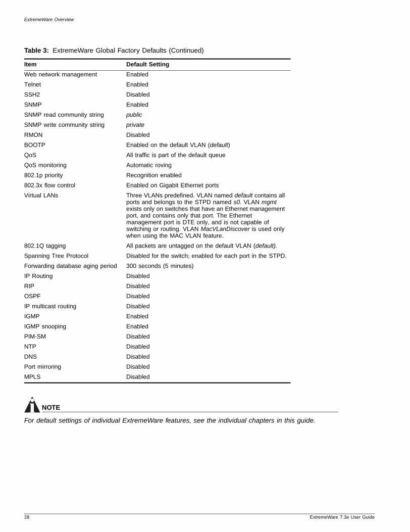
Table 3 shows factory defaults for global ExtremeWare features.
Table 3: ExtremeWare Global Factory Defaults
Item Default Setting
Serial or Telnet user account admin with no password and user with no password
.3e User Guide 27
ExtremeWare Overview
NOTE
For default settings of individual ExtremeWare features, see the individual chapters in this guide.
Web network management Enabled
Telnet Enabled
SSH2 Disabled
SNMP Enabled
SNMP read community string public
SNMP write community string private
RMON Disabled
BOOTP Enabled on the default VLAN (default)
QoS All traffic is part of the default queue
QoS monitoring Automatic roving
802.1p priority Recognition enabled
802.3x flow control Enabled on Gigabit Ethernet ports
Virtual LANs Three VLANs predefined. VLAN named default contains all ports and belongs to the STPD named s0. VLAN mgmt exists only on switches that have an Ethernet management port, and contains only that port. The Ethernet management port is DTE only, and is not capable of switching or routing. VLAN MacVLanDiscover is used only when using the MAC VLAN feature.
802.1Q tagging All packets are untagged on the default VLAN (default).
Spanning Tree Protocol Disabled for the switch; enabled for each port in the STPD.
Forwarding database aging period 300 seconds (5 minutes)
IP Routing Disabled
RIP Disabled
OSPF Disabled
IP multicast routing Disabled
IGMP Enabled
IGMP snooping Enabled
PIM-SM Disabled
NTP Disabled
DNS Disabled
Port mirroring Disabled
MPLS Disabled
Table 3: ExtremeWare Global Factory Defaults (Continued)
Item Default Setting
28 ExtremeWare 7.3e User Guide
2 Accessing the Switch
ExtremeWare 7
This chapter covers the following topics:
• Understanding the Command Syntax on page 29
• Line-Editing Keys on page 32
• Command History on page 33
• Common Commands on page 33
• Configuring Management Access on page 35
• Domain Name Service Client Services on page 38
• Checking Basic Connectivity on page 38
Understanding the Command Syntax
This section describes the steps to take when entering a command. Refer to the sections that follow for detailed information on using the command line interface.
ExtremeWare command syntax is described in detail in the ExtremeWare 7.3e Command Reference Guide. Some commands are also described in this user guide, in order to describe how to use the features of the ExtremeWare software. However, only a subset of commands are described here, and in some cases only a subset of the options that a command supports. The ExtremeWare 7.3e Command Reference Guide should be considered the definitive source for information on ExtremeWare commands.
When entering a command at the prompt, ensure that you have the appropriate privilege level. Most configuration commands require you to have the administrator privilege level. To use the command line interface (CLI), follow these steps:
1 Enter the command name.
If the command does not include a parameter or values, skip to step 3. If the command requires more information, continue to step 2.
2 If the command includes a parameter, enter the parameter name and values.
3 The value part of the command specifies how you want the parameter to be set. Values include numerics, strings, or addresses, depending on the parameter.
4 After entering the complete command, press [Return].
.3e User Guide 29
Accessing the Switch
NOTE
If an asterisk (*) appears in front of the command-line prompt, it indicates that you have outstanding configuration changes that have not been saved. For more information on saving configuration changes, see “Saving Configuration Changes” on page 228.
Syntax HelperThe CLI has a built-in syntax helper. If you are unsure of the complete syntax for a particular command, enter as much of the command as possible and press [Tab]. The syntax helper provides a list of options for the remainder of the command, and places the cursor at the end of the command you have entered so far, ready for the next option.
If the command is one where the next option is a named component, such as a VLAN, access profile, or route map, the syntax helper will also list any currently configured names that might be used as the next option. In situations where this list might be very long, the syntax helper will list only one line of names, followed by an ellipses to indicate that there are more names than can be displayed.
The syntax helper also provides assistance if you have entered an incorrect command.
Abbreviated Syntax
Abbreviated syntax is the shortest unambiguous allowable abbreviation of a command or parameter. Typically, this is the first three letters of the command. If you do not enter enough letters to allow the switch to determine which command you mean, the syntax helper will provide a list of the options based on the portion of the command you have entered.
NOTE
When using abbreviated syntax, you must enter enough characters to make the command unambiguous and distinguishable to the switch.
Command ShortcutsAll named components of the switch configuration must have a unique name. Components are typically named using one of the create commands. When you enter a command to configure a named component, you do not need to use the keyword of the component. For example, to create a VLAN, you must enter a unique VLAN name:
create vlan engineering
After you have created the VLAN with a unique name, you can then eliminate the keyword vlan from all other commands that require the name to be entered. For example, instead of entering the following command on a Summit 300 switch:
configure vlan engineering delete port 1:3,4:6
you could enter the following shortcut:
configure engineering delete port 1:3,4:6
Similarly, on a Summit 200 or Summit 300 switch, instead of entering the command
configure vlan engineering delete port 1-3,6
30 ExtremeWare 7.3e User Guide
Understanding the Command Syntax
ExtremeWare 7
you could enter the following shortcut:
configure engineering delete port 1-3,6
Summit 300-48 Numerical RangesCommands that require you to enter one or more port numbers use the parameter <portlist> in the syntax. A <portlist> can be one port on a particular slot. For example,
port 1:1
A <portlist> can be a range of numbers. For example,
port 1:1-1:3
You can add additional slot and port numbers to the list, separated by a comma:
port 1:1,1:8,1:10
You can specify all ports on a particular slot. For example,
port 1:*
indicates all ports on slot 13.
You can specify a range of slots and ports. For example,
port 1:3-2:5
indicates slot 1, port 3 through slot 2, port 5.
Summit 200, Summit 300-24 and Summit 400 Numerical RangesCommands that require you to enter one or more port numbers on either Summit 200, Summit 300-24, or Summit 400 switches use the parameter <portlist> in the syntax. A portlist can be a range of numbers, for example:
port 1-3
You can add additional port numbers to the list, separated by a comma:
port 1-3,6,8
NamesAll named components of the switch configuration must have a unique name. Names must begin with an alphabetical character and are delimited by whitespace, unless enclosed in quotation marks. Names are not case-sensitive. Names cannot be tokens used on the switch.
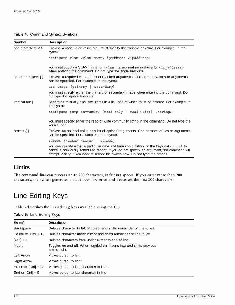
SymbolsYou may see a variety of symbols shown as part of the command syntax. These symbols explain how to enter the command, and you do not type them as part of the command itself. Table 4 summarizes command syntax symbols.
.3e User Guide 31
Accessing the Switch
LimitsThe command line can process up to 200 characters, including spaces. If you enter more than 200 characters, the switch generates a stack overflow error and processes the first 200 characters.
Line-Editing Keys
Table 5 describes the line-editing keys available using the CLI.
Table 4: Command Syntax Symbols
Symbol Description
angle brackets < > Enclose a variable or value. You must specify the variable or value. For example, in the syntax
configure vlan <vlan name> ipaddress <ipaddress>
you must supply a VLAN name for <vlan name> and an address for <ip_address> when entering the command. Do not type the angle brackets.
square brackets [ ] Enclose a required value or list of required arguments. One or more values or arguments can be specified. For example, in the syntax
use image [primary | secondary]
you must specify either the primary or secondary image when entering the command. Do not type the square brackets.
vertical bar | Separates mutually exclusive items in a list, one of which must be entered. For example, in the syntax
configure snmp community [read-only | read-write] <string>
you must specify either the read or write community string in the command. Do not type the vertical bar.
braces { } Enclose an optional value or a list of optional arguments. One or more values or arguments can be specified. For example, in the syntax
reboot {<date> <time> | cancel}
you can specify either a particular date and time combination, or the keyword cancel to cancel a previously scheduled reboot. If you do not specify an argument, the command will prompt, asking if you want to reboot the switch now. Do not type the braces.
Table 5: Line-Editing Keys
Key(s) Description
Backspace Deletes character to left of cursor and shifts remainder of line to left.
Delete or [Ctrl] + D Deletes character under cursor and shifts remainder of line to left.
[Ctrl] + K Deletes characters from under cursor to end of line.
Insert Toggles on and off. When toggled on, inserts text and shifts previous text to right.
Left Arrow Moves cursor to left.
Right Arrow Moves cursor to right.
Home or [Ctrl] + A Moves cursor to first character in line.
End or [Ctrl] + E Moves cursor to last character in line.
32 ExtremeWare 7.3e User Guide

Command History
ExtremeWare 7
Command History
ExtremeWare “remembers” the last 49 commands you entered. You can display a list of these commands by using the following command:
history
Common Commands
Table 6 describes some of the common commands used to manage the switch. Commands specific to a particular feature may also be described in other chapters of this guide. For a detailed description of the commands and their options, see the ExtremeWare 7.3e Command Reference Guide.
[Ctrl] + L Clears screen and movers cursor to beginning of line.
[Ctrl] + P orUp Arrow
Displays previous command in command history buffer and places cursor at end of command.
[Ctrl] + N orDown Arrow
Displays next command in command history buffer and places cursor at end of command.
[Ctrl] + U Clears all characters typed from cursor to beginning of line.
[Ctrl] + W Deletes previous word.
Table 6: Common Commands
Command Description
clear session <number> Terminates a Telnet session from the switch.
configure account <user account> {encrypted} {<password>}
Configures a user account password.
The switch will interactively prompt for a new password, and for reentry of the password to verify it. Passwords must have a minimum of 1 character and can have a maximum of 30 characters. Passwords are case-sensitive; user names are not case sensitive.
configure banner Configures the banner string. You can enter up to 24 rows of 79-column text that is displayed before the login prompt of each session. Press [Return] at the beginning of a line to terminate the command and apply the banner. To clear the banner, press [Return] at the beginning of the first line.
configure banner netlogin Configures the network login banner string. You can enter up to 1024 characters to be displayed before the login prompt of each session.
configure ports [<portlist> | all | mgmt] auto off {speed [10 | 100 | 1000]} duplex [half | full]
Manually configures the port speed and duplex setting of one or more ports on a switch.
configure ssh2 key {pregenerated} Generates the SSH2 host key.
Table 5: Line-Editing Keys (Continued)
Key(s) Description
.3e User Guide 33
Accessing the Switch
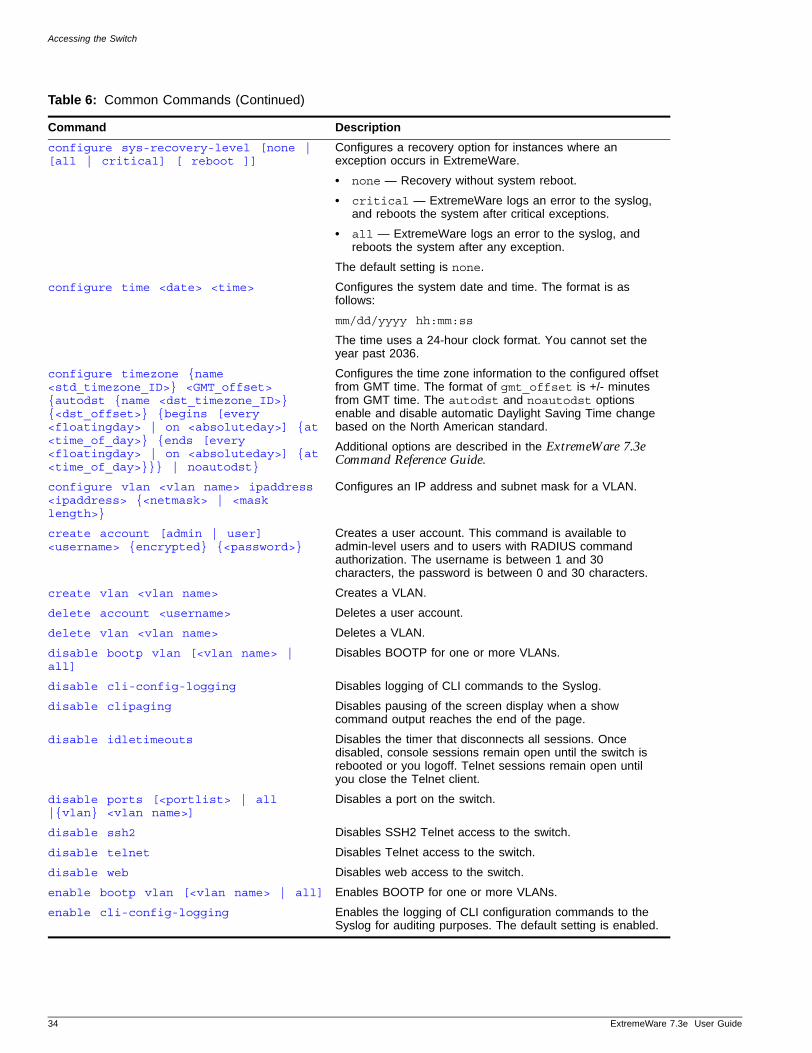
configure sys-recovery-level [none | [all | critical] [ reboot ]]
Configures a recovery option for instances where an exception occurs in ExtremeWare.
• none — Recovery without system reboot.
• critical — ExtremeWare logs an error to the syslog, and reboots the system after critical exceptions.
• all — ExtremeWare logs an error to the syslog, and reboots the system after any exception.
The default setting is none.
configure time <date> <time> Configures the system date and time. The format is as follows:
mm/dd/yyyy hh:mm:ss
The time uses a 24-hour clock format. You cannot set the year past 2036.
configure timezone {name <std_timezone_ID>} <GMT_offset> {autodst {name <dst_timezone_ID>} {<dst_offset>} {begins [every <floatingday> | on <absoluteday>] {at <time_of_day>} {ends [every <floatingday> | on <absoluteday>] {at <time_of_day>}}} | noautodst}
Configures the time zone information to the configured offset from GMT time. The format of gmt_offset is +/- minutes from GMT time. The autodst and noautodst options enable and disable automatic Daylight Saving Time change based on the North American standard.
Additional options are described in the ExtremeWare 7.3e Command Reference Guide.
configure vlan <vlan name> ipaddress <ipaddress> {<netmask> | <mask length>}
Configures an IP address and subnet mask for a VLAN.
create account [admin | user] <username> {encrypted} {<password>}
Creates a user account. This command is available to admin-level users and to users with RADIUS command authorization. The username is between 1 and 30 characters, the password is between 0 and 30 characters.
create vlan <vlan name> Creates a VLAN.
delete account <username> Deletes a user account.
delete vlan <vlan name> Deletes a VLAN.
disable bootp vlan [<vlan name> | all]
Disables BOOTP for one or more VLANs.
disable cli-config-logging Disables logging of CLI commands to the Syslog.
disable clipaging Disables pausing of the screen display when a show command output reaches the end of the page.
disable idletimeouts Disables the timer that disconnects all sessions. Once disabled, console sessions remain open until the switch is rebooted or you logoff. Telnet sessions remain open until you close the Telnet client.
disable ports [<portlist> | all |{vlan} <vlan name>]
Disables a port on the switch.
disable ssh2 Disables SSH2 Telnet access to the switch.
disable telnet Disables Telnet access to the switch.
disable web Disables web access to the switch.
enable bootp vlan [<vlan name> | all] Enables BOOTP for one or more VLANs.
enable cli-config-logging Enables the logging of CLI configuration commands to the Syslog for auditing purposes. The default setting is enabled.
Table 6: Common Commands (Continued)
Command Description
34 ExtremeWare 7.3e User Guide
Configuring Management Access
ExtremeWare 7
Configuring Management Access
ExtremeWare supports the following two levels of management:
• User
• Administrator
In addition to the management levels, you can optionally use an external RADIUS server to provide CLI command authorization checking for each command. For more information on RADIUS, see “RADIUS Client” in Chapter 2.
User Account
A user-level account has viewing access to all manageable parameters, with the exception of:
• User account database.
• SNMP community strings.
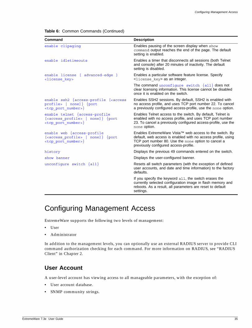
enable clipaging Enables pausing of the screen display when show command output reaches the end of the page. The default setting is enabled.
enable idletimeouts Enables a timer that disconnects all sessions (both Telnet and console) after 20 minutes of inactivity. The default setting is disabled.
enable license [ advanced-edge ] <license_key>
Enables a particular software feature license. Specify <license_key> as an integer.
The command unconfigure switch {all} does not clear licensing information. This license cannot be disabled once it is enabled on the switch.
enable ssh2 {access-profile [<access profile> | none]} {port <tcp_port_number>}
Enables SSH2 sessions. By default, SSH2 is enabled with no access profile, and uses TCP port number 22. To cancel a previously configured access-profile, use the none option.
enable telnet {access-profile [<access_profile> | none]} {port <tcp_port_number>}
Enables Telnet access to the switch. By default, Telnet is enabled with no access profile, and uses TCP port number 23. To cancel a previously configured access-profile, use the none option.
enable web {access-profile [<access_profile> | none]} {port <tcp_port_number>}
Enables ExtremeWare Vista™ web access to the switch. By default, web access is enabled with no access profile, using TCP port number 80. Use the none option to cancel a previously configured access-profile.
history Displays the previous 49 commands entered on the switch.
show banner Displays the user-configured banner.
unconfigure switch {all} Resets all switch parameters (with the exception of defined user accounts, and date and time information) to the factory defaults.
If you specify the keyword all, the switch erases the currently selected configuration image in flash memory and reboots. As a result, all parameters are reset to default settings.
Table 6: Common Commands (Continued)
Command Description
.3e User Guide 35
Accessing the Switch
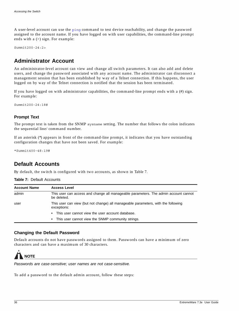
A user-level account can use the ping command to test device reachability, and change the password assigned to the account name. If you have logged on with user capabilities, the command-line prompt ends with a (>) sign. For example:
Summit200-24:2>
Administrator AccountAn administrator-level account can view and change all switch parameters. It can also add and delete users, and change the password associated with any account name. The administrator can disconnect a management session that has been established by way of a Telnet connection. If this happens, the user logged on by way of the Telnet connection is notified that the session has been terminated.
If you have logged on with administrator capabilities, the command-line prompt ends with a (#) sign. For example:
Summit200-24:18#
Prompt Text
The prompt text is taken from the SNMP sysname setting. The number that follows the colon indicates the sequential line/command number.
If an asterisk (*) appears in front of the command-line prompt, it indicates that you have outstanding configuration changes that have not been saved. For example:
*Summit400-48:19#
Default AccountsBy default, the switch is configured with two accounts, as shown in Table 7.
Changing the Default Password
Default accounts do not have passwords assigned to them. Passwords can have a minimum of zero characters and can have a maximum of 30 characters.
NOTE
Passwords are case-sensitive; user names are not case-sensitive.
To add a password to the default admin account, follow these steps:
Table 7: Default Accounts
Account Name Access Level
admin This user can access and change all manageable parameters. The admin account cannot be deleted.
user This user can view (but not change) all manageable parameters, with the following exceptions:
• This user cannot view the user account database.
• This user cannot view the SNMP community strings.
36 ExtremeWare 7.3e User Guide
Configuring Management Access
ExtremeWare 7
1 Log in to the switch using the name admin.
2 At the password prompt, press [Return].
3 Add a default admin password by entering the following command:
configure account admin
4 Enter the new password at the prompt.
5 Re-enter the new password at the prompt.
To add a password to the default user account, follow these steps:
1 Log in to the switch using the name admin.
2 At the password prompt, press [Return], or enter the password that you have configured for the admin account.
3 Add a default user password by entering the following command:
configure account user
4 Enter the new password at the prompt.
5 Re-enter the new password at the prompt.
NOTE
If you forget your password while logged out of the command line interface, contact your local technical support representative, who will advise on your next course of action.
Creating a Management AccountThe switch can have a total of 16 management accounts. You can use the default names (admin and user), or you can create new names and passwords for the accounts. Passwords can have a minimum of 0 characters and can have a maximum of 30 characters.
To create a new account, follow these steps:
1 Log in to the switch as admin.
2 At the password prompt, press [Return], or enter the password that you have configured for the admin account.
3 Add a new user by using the following command:
create account [admin | user] <username>
4 Enter the password at the prompt.
Viewing Accounts
To view the accounts that have been created, you must have administrator privileges. Use the following command to see the accounts:
show accounts
Deleting an Account
To delete a account, you must have administrator privileges. To delete an account, use the following command:
.3e User Guide 37
Accessing the Switch
delete account <username>
NOTE
Do not delete the default administrator account. If you do, it is automatically restored, with no password, the next time you download a configuration. To ensure security, change the password on the default account, but do not delete it. The changed password will remain intact through configuration uploads and downloads. If you must delete the default account, first create another administrator-level account. Remember to manually delete the default account again every time you download a configuration.
Domain Name Service Client Services
The Domain Name Service (DNS) client in ExtremeWare augments the following commands to allow them to accept either IP addresses or host names:
• telnet
• download bootrom
• download configuration
• download image
• upload configuration
• ping
• traceroute
In addition, the nslookup utility can be used to return the IP address of a hostname.
You can specify up to eight DNS servers for use by the DNS client using the following command:
configure dns-client add <ipaddress>
You can specify a default domain for use when a host name is used without a domain. Use the following command:
configure dns-client default-domain <domain_name>
For example, if you specify the domain “xyz-inc.com” as the default domain, then a command such as ping accounting1 will be taken as if it had been entered ping accounting1.xyz-inc.com.
Checking Basic Connectivity
The switch offers the following commands for checking basic connectivity:
• ping
• traceroute
PingThe ping command enables you to send Internet Control Message Protocol (ICMP) echo messages to a remote IP device. The ping command is available for both the user and administrator privilege level.
38 ExtremeWare 7.3e User Guide

Checking Basic Connectivity
ExtremeWare 7
The ping command syntax is:
ping {udp} {continuous} {start-size <size number> {-<end_size}} [<ip_address> | <hostname>] {from <src_ipaddress> | with record-route | from <src_ipaddress> with record-route}
Options for the ping command are described in Table 8.
If a ping request fails, the switch continues to send ping messages until interrupted. Press any key to interrupt a ping request. The statistics are tabulated after the ping is interrupted.
TracerouteThe traceroute command enables you to trace the routed path between the switch and a destination endstation. The traceroute command syntax is:
traceroute <host name | ip_address> {from <source IP address>} {ttl <number>} {port <port number>}
where:
• ip_address is the IP address of the destination endstation.
• hostname is the hostname of the destination endstation. To use the hostname, you must first configure DNS.
• from uses the specified source address in the ICMP packet. If not specified, the address of the transmitting interface is used.
• ttl configures the switch to trace the hops until the time-to-live has been exceeded for the switch.
• port uses the specified UDP port number.
Table 8: Ping Command Parameters
Parameter Description
udp Specifies that UDP messages should be sent instead of ICMP echo messages. When specified, from and with record-route options are not supported.
continuous Specifies ICMP echo messages to be sent continuously. This option can be interrupted by pressing any key.
size Specifies the size of the ICMP request. If both the start_size and end_size are specified, transmits ICMP requests using 1 byte increments, per packet. If no end_size is specified, packets of start_size are sent.
<ipaddress> Specifies the IP address of the host.
<hostname> Specifies the name of the host. To use the hostname, you must first configure DNS.
from Uses the specified source address in the ICMP packet. If not specified, the address of the transmitting interface is used.
with record-route Decodes the list of recorded routes and displays them when the ICMP echo reply is received.
.3e User Guide 39

Accessing the Switch
40 ExtremeWare 7.3e User Guide
3 Managing the Switch
ExtremeWare 7
This chapter covers the following topics:
• Overview on page 41
• Using the Console Interface on page 42
• Using the 10/100/1000 Ethernet Management Port (Summit 400 only) on page 42
• Using Telnet on page 42
• Using Secure Shell 2 (SSH2) on page 46
• Using SNMP on page 46
• Authenticating Users on page 58
• Using Network Login on page 59
• Using the Simple Network Time Protocol on page 59
Overview
Using ExtremeWare, you can manage the switch using the following methods:
• Access the CLI by connecting a terminal (or workstation with terminal-emulation software) to the console port.
• Access the switch remotely using TCP/IP through one of the switch ports or through the dedicated 10/100/1000 unshielded twisted pair (UTP) Ethernet management port (on switches that are so equipped). Remote access includes:
— Telnet using the CLI interface.
— SSH2 using the CLI interface.
— ExtremeWare Vista web access using a standard web browser.
— SNMP access using EPICenter or another SNMP manager.
• Download software updates and upgrades. For more information, see Chapter 11, Software Upgrade and Boot Options.
.3e User Guide 41
Managing the Switch
The switch supports up to the following number of concurrent user sessions:
• One console session
• Eight Telnet sessions
• Eight SSH2 sessions
• One web session
Using the Console Interface
The CLI built into the switch is accessible by way of the 9-pin, RS-232 port labeled console. The console is located on the front of Summit “e” series switches. For more information on the console port pinouts, see the Consolidated “e” Series Hardware Installation Guide.
After the connection has been established, you will see the switch prompt and you can log in.
Using the 10/100/1000 Ethernet Management Port (Summit 400 only)
The Summit 400 provides a dedicated 10/100/1000 Ethernet management port. This port, located on the back panel of the Summit 400, provides dedicated remote access to the switch using TCP/IP. It supports the following management methods:
Telnet using the CLI interface
• ExtremeWare Vista web access using a standard web browser
• SNMP access using EPICenter or another SNMP manager
The management port is a DTE port, and is not capable of supporting switching or routing functions. The TCP/IP configuration for the management port is done using the same syntax as used for VLAN configuration. The VLAN mgmt comes pre configured with only the 10/100/1000 UTP management port as a member.
You can configure the IP address, subnet mask, and default router for the VLAN mgmt, using the configure vlan ipaddress and the configure iproute add default commands:
for example:
configure vlan mgmt ipaddress 105.211.39.55/24
configure iproute add default 123.45.67.1
Using Telnet
Any workstation with a Telnet facility should be able to communicate with the switch over a TCP/IP network using VT-100 terminal emulation.
Up to eight active Telnet sessions can access the switch concurrently. If idletimeouts are enabled, the Telnet connection will time out after 20 minutes of inactivity. If a connection to a Telnet session is lost inadvertently, the switch terminates the session within two hours.
42 ExtremeWare 7.3e User Guide
Using Telnet
ExtremeWare 7
Before you can start a Telnet session, you must set up the IP parameters described in “Configuring Switch IP Parameters” later in this chapter. Telnet is enabled by default.
NOTE
Maximize the Telnet screen so that automatically updating screens display correctly.
To open the Telnet session, you must specify the IP address of the device that you want to manage. Check the user manual supplied with the Telnet facility if you are unsure of how to do this.
After the connection is established, you will see the switch prompt and you may log in.
Connecting to Another Host Using TelnetYou can Telnet from the current CLI session to another host using the following command:
telnet [<ipaddress> | <hostname>] {<port_number>}
If the TCP port number is not specified, the Telnet session defaults to port 23. Only VT100 emulation is supported.
Configuring Switch IP ParametersTo manage the switch by way of a Telnet connection or by using an SNMP Network Manager, you must first configure the switch IP parameters.
Using a BOOTP Server
If you are using IP and you have a Bootstrap Protocol (BOOTP) server set up correctly on your network, you must provide the following information to the BOOTP server:
• Switch Media Access Control (MAC) address, found on the rear label of the switch, or from a show switch command
• IP address
• Subnet address mask (optional)
After this is done, the IP address and subnet mask for the switch will be downloaded automatically. You can then start managing the switch using this addressing information without further configuration.
You can enable BOOTP on a per-VLAN basis by using the following command:
enable bootp vlan [<vlan name> | all]
By default, BOOTP is enabled on the default VLAN.
To enable the forwarding of BOOTP and Dynamic Host Configuration Protocol (DHCP) requests, use the following command:
enable bootprelay
.3e User Guide 43
Managing the Switch
If you configure the switch to use BOOTP, the switch IP address is not retained through a power cycle, even if the configuration has been saved. To retain the IP address through a power cycle, you must configure the IP address of the VLAN using the command-line interface, Telnet, or web interface.
All VLANs within a switch that are configured to use BOOTP to get their IP address use the same MAC address. Therefore, if you are using BOOTP relay through a router, the BOOTP server relays packets based on the gateway portion of the BOOTP packet.
NOTE
For more information on DHCP/BOOTP relay, see Chapter 12.
Manually Configuring the IP Settings
If you are using IP without a BOOTP server, you must enter the IP parameters for the switch in order for the SNMP Network Manager, Telnet software, or web interface to communicate with the device. To assign IP parameters to the switch, you must perform the following tasks:
• Log in to the switch with administrator privileges using the console interface.
• Assign an IP address and subnet mask to a VLAN.
The switch comes configured with a default VLAN named default. To use Telnet or an SNMP Network Manager, you must have at least one VLAN on the switch, and it must be assigned an IP address and subnet mask. IP addresses are always assigned to each VLAN. The switch can be assigned multiple IP addresses.
NOTE
For information on creating and configuring VLANs, see Chapter 5.
To manually configure the IP settings, follow these steps:
1 Connect a terminal or workstation running terminal-emulation software to the console port, as detailed in “Using the Console Interface” on page 42.
2 At your terminal, press [Return] one or more times until you see the login prompt.
3 At the login prompt, enter your user name and password. Note that they are both case-sensitive. Ensure that you have entered a user name and password with administrator privileges.
— If you are logging in for the first time, use the default user name admin to log in with administrator privileges. For example:
login: admin
Administrator capabilities enable you to access all switch functions. The default user names have no passwords assigned.
— If you have been assigned a user name and password with administrator privileges, enter them at the login prompt.
4 At the password prompt, enter the password and press [Return].
When you have successfully logged in to the switch, the command-line prompt displays the name of the switch in its prompt.
5 Assign an IP address and subnetwork mask for the default VLAN by using the following command:
configure vlan <vlan name> ipaddress <ipaddress> {<netmask> | <mask length>}
For example:
44 ExtremeWare 7.3e User Guide
Using Telnet
ExtremeWare 7
configure vlan default ipaddress 123.45.67.8 255.255.255.0
Your changes take effect immediately.
NOTE
As a general rule, when configuring any IP addresses for the switch, you can express a subnet mask by using dotted decimal notation, or by using classless inter-domain routing notation (CIDR). CIDR uses a forward slash plus the number of bits in the subnet mask. Using CIDR notation, the command identical to the one above would be:
configure vlan default ipaddress 123.45.67.8 / 24
6 Configure the default route for the switch using the following command:
configure iproute add default <gateway> {<metric>}
For example:
configure iproute add default 123.45.67.1
7 Save your configuration changes so that they will be in effect after the next switch reboot, by using the following command:
save configuration {primary | secondary}
8 When you are finished using the facility, log out of the switch by typing:
logout or quit
Disconnecting a Telnet SessionAn administrator-level account can disconnect a Telnet management session. If this happens, the user logged in by way of the Telnet connection is notified that the session has been terminated.
To terminate a Telnet session, follow these steps:
1 Log in to the switch with administrator privileges.
2 Determine the session number of the session you want to terminate by using the following command:
show session
3 Terminate the session by using the following command:
clear session <number>
Controlling Telnet AccessBy default, Telnet services are enabled on the switch. Telnet access can be restricted by the use of an access profile. An access profile permits or denies a named list of IP addresses and subnet masks. To configure Telnet to use an access profile, use the following command:
enable telnet {access-profile [<access_profile> | none]} {port <tcp_port_number>}
Use the none option to remove a previously configured access profile.
To display the status of Telnet, use the following command:
show management
You can choose to disable Telnet by using the following command:
.3e User Guide 45
Managing the Switch
disable telnet
To re-enable Telnet on the switch, at the console port use the following:
enable telnet {access-profile [<access_profile> | none]} {port <tcp_port_number>}
You must be logged in as an administrator to enable or disable Telnet.
NOTE
For more information on Access Profiles, see Chapter 9.
Using Secure Shell 2 (SSH2)
Secure Shell 2 (SSH2) is a feature of ExtremeWare that allows you to encrypt Telnet session data between a network administrator using SSH2 client software and the switch, or to send encrypted data from the switch to an SSH2 client on a remote system. Image and configuration files may also be transferred to the switch using the Secure Copy Protocol 2 (SCP2). The ExtremeWare CLI provides a command that enable the switch to function as an SSH2 client, sending commands to a remote system via an SSH2 session. It also provides commands to copy image and configuration files to the switch using the SCP2.
For detailed information about SSH2 and SCP2, see Chapter 9, “Security”.
Using SNMP
Any Network Manager running the Simple Network Management Protocol (SNMP) can manage the switch, provided the Management Information Base (MIB) is installed correctly on the management station. Each Network Manager provides its own user interface to the management facilities.
The following sections describe how to get started if you want to use an SNMP manager. It assumes you are already familiar with SNMP management. If not, refer to the following publication:
The Simple Book by Marshall T. RoseISBN 0-13-8121611-9Published by Prentice Hall.
Enabling and Disabling SNMPv1/v2c and SNMPv3ExtremeWare versions since 7.2e can concurrently support SNMPv1/v2c and SNMPv3. The default for the switch is to have both types of SNMP enabled. Network managers can access the device with either SNMPv1/v2c methods or SNMPv3. To enable concurrent support, use the following command:
enable snmp access
To prevent any type of SNMP access, use the following command:
disable dhcp ports <portlist> vlan <vlan name>
46 ExtremeWare 7.3e User Guide
Using SNMP
ExtremeWare 7
To prevent access using SNMPv1/v2c methods and allow access using SNMPv3 methods only, use the following commands:
enable snmp accessdisable snmp access {snmp-v1v2c}
There is no way to configure the switch to allow SNMPv1/v2c access and prevent SNMPv3 access.
Most of the commands that support SNMPv1/v2c use the keyword snmp, most of the commands that support SNMPv3 use the keyword snmpv3.
Accessing Switch AgentsTo have access to the SNMP agent residing in the switch, at least one VLAN must have an IP address assigned to it.
By default, SNMP access and SNMPv1/v2c traps are enabled. SNMP access and SNMP traps can be disabled and enabled independently—you can disable SNMP access but still allow SNMP traps to be sent, or vice versa.
Supported MIBsIn addition to private MIBs, the switch supports the standard MIBs listed in Appendix A.
NOTE
The SNMP ifAdminStatus MIB value is not saved after a reboot. Ports set to down in the SNMP ifAdminStatus MIB come back after rebooting. However, if you save the configuration using the CLI or SNMP after changing the port status to down in the ifAdminStatus MIB, then the change is saved after a reboot.
Configuring SNMPv1/v2c SettingsThe following SNMPv1/v2c parameters can be configured on the switch:
• Authorized trap receivers—An authorized trap receiver can be one or more network management stations on your network. The switch sends SNMPv1/v2c traps to all trap receivers. You can have a maximum of 16 trap receivers configured for each switch, and you can specify a community string and UDP port for individually for each trap receiver. All community strings must also be added to the switch using the configure snmp add community command.
To configure a trap receiver on a switch, use the following command:
configure snmp add trapreceiver <ip address> {port <number>} community {hex <hex value>} <community string> {from <source ip address>} {mode [enhanced | standard]} trap-group {auth-traps{,}} {extreme-traps{,}} {link-up-down-traps{,}} {ospf-traps{,} {ping-traceroute-traps{,}} {rmon-traps{,}} {security-traps{,}} {smart-traps{,}} {stp-traps{,}} {system-traps{,}} {vrrp-traps{,}}
See the Command Reference for a listing of the available traps.
You can delete a trap receiver using the configure snmp delete trapreceiver [{<ip address> {port <number>}} | {all}] command.
Entries in the trap receiver list can also be created, modified, and deleted using the RMON2 trapDestTable MIB variable, as described in RFC 2021.
.3e User Guide 47
Managing the Switch
• SNMP read access—The ability to read SNMP information can be restricted through the use of an access profile. An access profile permits or denies a named list of IP addresses and subnet masks.
To configure SNMPv1/v2c read access to use an access profile, use the following command:
configure snmp access-profile readonly [<access-profile> | none]
Use the none option to remove a previously configured access profile.
• SNMP read/write access—The ability to read and write SNMP information can be restricted through the use of an access profile. An access profile permits or denies a named list of IP addresses and subnet masks.
To configure SNMPv1/v2c read/write access to use an access profile, use the following command:
configure snmp access-profile readwrite [<access-profile> | none]
Use the none option to remove a previously configured access-profile.
• Community strings—The community strings allow a simple method of authentication between the switch and the remote Network Manager. There are three types of community strings on “e” series switches:
— Read community strings provide read-only access to the switch. The default read-only community string is public.
— Read-write community strings provide read and write access to the switch. The default read-write community string is private.
— Encrypted community strings provide encryption and are only used when uploading or downloading a configuration.
To configure a community string, use the following command:
configure snmp add community [readonly | readwrite] {encrypted} <alphanumeric string>
• System contact (optional)—The system contact is a text field that enables you to enter the name of the person(s) responsible for managing the switch.
To configure this optional field, enter this command:
configure snmp syscontact <alphanumeric string>
• System name—The system name is the name that you have assigned to this switch. The default name is the model name of the switch (for example, Summit200 switch).
To configure the system name, enter this command:
configure snmp sysname <alphanumeric string>
• System location (optional)—Using the system location field, you can enter an optional location for this switch.
To configure the system location, enter this command:
configure snmp syslocation <alphanumeric string>
• Enabling/disabling link up and link down traps (optional)—By default, link up and link down traps (also called port-up-down traps) are enabled on the switch for all ports. SNMPv1 traps for link up and link down are not supported; ExtremeWare uses SNMPv2 traps.
You can disable or re-enable the sending of these traps on a per port basis, by using the following commands:
disable snmp traps port-up-down ports [all | mgmt | <portlist>]
enable snmp traps {port-up-down ports [all | mgmt | <portlist>]}
The mgmt option will only appear on platforms having a management port.
48 ExtremeWare 7.3e User Guide
Using SNMP
ExtremeWare 7
• Enabling/disabling MAC-security traps (optional)—MAC-security traps are sent on ports when limit-learning is configured and a new MAC address appears on the port after the port has already learned MAC addresses up to the configured limit. At such instants, a log message is generated in the syslog, a trap is sent out and the port is blackholed. By default, MAC-security traps are disabled on the switch. To enable or re-disable them, the following commands must be used:
enable snmp traps mac-security
disable snmp traps mac-security
• Enabling/disabling cable diagnostics—These diagnostic commands allow you to find problems with Ethernet cables. For full details on using this feature, see “Cable Diagnostics” on page 236.
NOTE
To configure learning limits on a set of ports, the command configure ports <portlist> limit-learning can be used.
Displaying SNMP SettingsTo display the SNMP settings configured on the switch, use the following command:
show management
This command displays the following information:
• Enable/disable state for Telnet, SSH2, SNMP, and web access, along with access profile information
• SNMP community strings
• Authorized SNMP station list
• SNMP MAC-security traps
• Link up/ link down traps enabled on ports
• SNMP trap receiver list
• SNMP trap groups
• RMON polling configuration
• Login statistics
• Enable/disable status of link up and link down traps
• Enable/disable status of MAC-security traps
• CLI idle timeouts
• CLI paging
• CLI configuration logging
• CLI prompt number
SNMP Trap GroupsSNMP trap groups allow you to specify which SNMP traps to send to a particular trap receiver. This functionality was made possible by the underlying support for SNMPv3. Essentially, a number of predefined filters are associated with a trap receiver, so that only those traps are sent. If you have already been using SNMPv1/v2c trap receivers, trap groups are very easy to incorporate into your network. You cannot define your own trap groups. If you need to define more selectively which notifications to receive, you will need to use the notification filter capabilities available in SNMPv3.
.3e User Guide 49
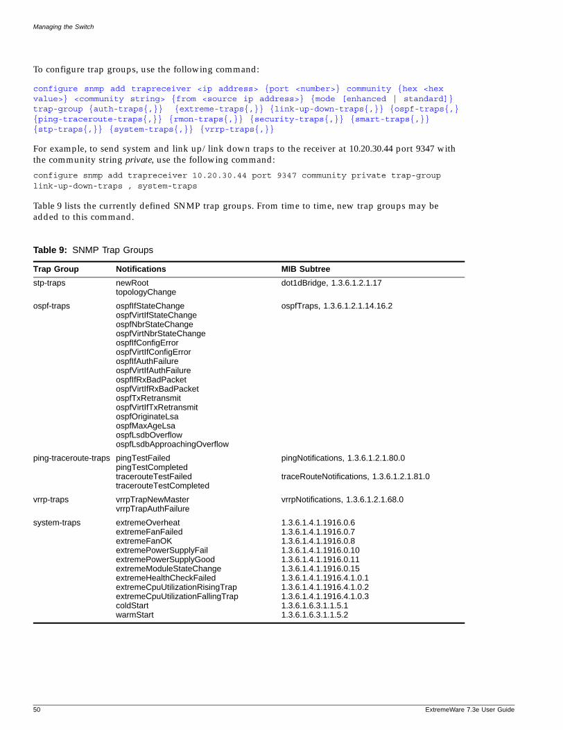
Managing the Switch
To configure trap groups, use the following command:
configure snmp add trapreceiver <ip address> {port <number>} community {hex <hex value>} <community string> {from <source ip address>} {mode [enhanced | standard]} trap-group {auth-traps{,}} {extreme-traps{,}} {link-up-down-traps{,}} {ospf-traps{,} {ping-traceroute-traps{,}} {rmon-traps{,}} {security-traps{,}} {smart-traps{,}} {stp-traps{,}} {system-traps{,}} {vrrp-traps{,}}
For example, to send system and link up/link down traps to the receiver at 10.20.30.44 port 9347 with the community string private, use the following command:
configure snmp add trapreceiver 10.20.30.44 port 9347 community private trap-group link-up-down-traps , system-traps
Table 9 lists the currently defined SNMP trap groups. From time to time, new trap groups may be added to this command.
Table 9: SNMP Trap Groups
Trap Group Notifications MIB Subtree
stp-traps newRoot topologyChange
dot1dBridge, 1.3.6.1.2.1.17
ospf-traps ospfIfStateChange ospfVirtIfStateChange ospfNbrStateChange ospfVirtNbrStateChange ospfIfConfigError ospfVirtIfConfigError ospfIfAuthFailure ospfVirtIfAuthFailure ospfIfRxBadPacket ospfVirtIfRxBadPacket ospfTxRetransmit ospfVirtIfTxRetransmit ospfOriginateLsa ospfMaxAgeLsa ospfLsdbOverflow ospfLsdbApproachingOverflow
ospfTraps, 1.3.6.1.2.1.14.16.2
ping-traceroute-traps pingTestFailed pingTestCompleted tracerouteTestFailed tracerouteTestCompleted
pingNotifications, 1.3.6.1.2.1.80.0
traceRouteNotifications, 1.3.6.1.2.1.81.0
vrrp-traps vrrpTrapNewMaster vrrpTrapAuthFailure
vrrpNotifications, 1.3.6.1.2.1.68.0
system-traps extremeOverheat extremeFanFailed extremeFanOK extremePowerSupplyFail extremePowerSupplyGood extremeModuleStateChange extremeHealthCheckFailed extremeCpuUtilizationRisingTrap extremeCpuUtilizationFallingTrap coldStart warmStart
1.3.6.1.4.1.1916.0.61.3.6.1.4.1.1916.0.71.3.6.1.4.1.1916.0.81.3.6.1.4.1.1916.0.101.3.6.1.4.1.1916.0.111.3.6.1.4.1.1916.0.151.3.6.1.4.1.1916.4.1.0.11.3.6.1.4.1.1916.4.1.0.21.3.6.1.4.1.1916.4.1.0.31.3.6.1.6.3.1.1.5.11.3.6.1.6.3.1.1.5.2
50 ExtremeWare 7.3e User Guide
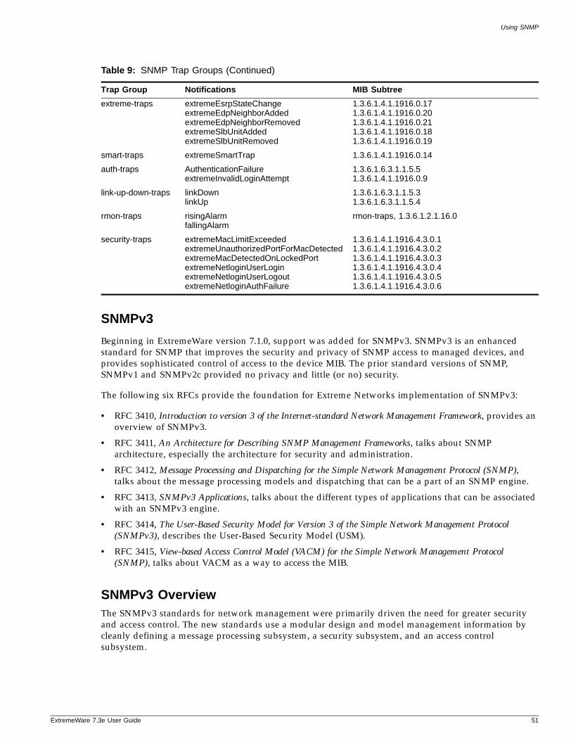
Using SNMP
ExtremeWare 7
SNMPv3
Beginning in ExtremeWare version 7.1.0, support was added for SNMPv3. SNMPv3 is an enhanced standard for SNMP that improves the security and privacy of SNMP access to managed devices, and provides sophisticated control of access to the device MIB. The prior standard versions of SNMP, SNMPv1 and SNMPv2c provided no privacy and little (or no) security.
The following six RFCs provide the foundation for Extreme Networks implementation of SNMPv3:
• RFC 3410, Introduction to version 3 of the Internet-standard Network Management Framework, provides an overview of SNMPv3.
• RFC 3411, An Architecture for Describing SNMP Management Frameworks, talks about SNMP architecture, especially the architecture for security and administration.
• RFC 3412, Message Processing and Dispatching for the Simple Network Management Protocol (SNMP), talks about the message processing models and dispatching that can be a part of an SNMP engine.
• RFC 3413, SNMPv3 Applications, talks about the different types of applications that can be associated with an SNMPv3 engine.
• RFC 3414, The User-Based Security Model for Version 3 of the Simple Network Management Protocol (SNMPv3), describes the User-Based Security Model (USM).
• RFC 3415, View-based Access Control Model (VACM) for the Simple Network Management Protocol (SNMP), talks about VACM as a way to access the MIB.
SNMPv3 OverviewThe SNMPv3 standards for network management were primarily driven the need for greater security and access control. The new standards use a modular design and model management information by cleanly defining a message processing subsystem, a security subsystem, and an access control subsystem.
extreme-traps extremeEsrpStateChangeextremeEdpNeighborAddedextremeEdpNeighborRemovedextremeSlbUnitAddedextremeSlbUnitRemoved
1.3.6.1.4.1.1916.0.171.3.6.1.4.1.1916.0.201.3.6.1.4.1.1916.0.211.3.6.1.4.1.1916.0.181.3.6.1.4.1.1916.0.19
smart-traps extremeSmartTrap 1.3.6.1.4.1.1916.0.14
auth-traps AuthenticationFailureextremeInvalidLoginAttempt
1.3.6.1.6.3.1.1.5.51.3.6.1.4.1.1916.0.9
link-up-down-traps linkDownlinkUp
1.3.6.1.6.3.1.1.5.31.3.6.1.6.3.1.1.5.4
rmon-traps risingAlarmfallingAlarm
rmon-traps, 1.3.6.1.2.1.16.0
security-traps extremeMacLimitExceededextremeUnauthorizedPortForMacDetectedextremeMacDetectedOnLockedPortextremeNetloginUserLoginextremeNetloginUserLogoutextremeNetloginAuthFailure
1.3.6.1.4.1.1916.4.3.0.11.3.6.1.4.1.1916.4.3.0.21.3.6.1.4.1.1916.4.3.0.31.3.6.1.4.1.1916.4.3.0.41.3.6.1.4.1.1916.4.3.0.51.3.6.1.4.1.1916.4.3.0.6
Table 9: SNMP Trap Groups (Continued)
Trap Group Notifications MIB Subtree
.3e User Guide 51
Managing the Switch
The message processing (MP) subsystem helps identify the MP model to be used when processing a received Protocol Data Unit (PDU), the packets used by SNMP for communication. This layer helps in implementing a multi-lingual agent, so that various versions of SNMP can coexist simultaneously in the same network.
The security subsystem features the use of various authentication and privacy protocols with various timeliness checking and engine clock synchronization schemes. SNMPv3 is designed to be secure against:
• Modification of information, where an in-transit message is altered.
• Masquerades, where an unauthorized entity assumes the identity of an authorized entity.
• Message stream modification, where packets are delayed and/or replayed.
• Disclosure, where packet exchanges are sniffed (examined) and information is learned about the contents.
The access control subsystem provides the ability to configure whether access to a managed object in a local MIB is allowed for a remote principal. The access control scheme allows you to define access policies based on MIB views, groups, and multiple security levels.
In addition, the SNMPv3 target and notification MIBs provide a more procedural approach for the generation and filtering of notifications.
SNMPv3 objects are stored in non-volatile memory unless specifically assigned to volatile storage. Objects defined as permanent cannot be deleted or modified.
NOTE
In SNMPv3, many objects can be identified by a human-readable string or by a string of hex octets. In many commands, you can use either a character string, or a colon separated string of hex octets to specify objects. This is indicated by the keyword hex used in the command.
Message ProcessingA particular network manager may require messages that conform to a particular version of SNMP. The choice of the SNMPv1, SNMPv2, or SNMPv3 message processing model can be configured for each network manager as its target address is configured. The selection of the message processing model is configured with the mp-model keyword in the following command:
configure snmpv3 add target-params [hex <hex value> | <param name>] user [hex <hex value> | <user name>] mp-model [snmpv1 | snmpv2c | snmpv3] sec-model [snmpv1 | snmpv2c | usm] {sec-level [noauth | authnopriv | priv]} {volatile}
SNMPv3 Security
In SNMPv3 the User-Based Security Model (USM) for SNMP was introduced. USM deals with security related aspects like authentication, encryption of SNMP messages and defining users and their various access security levels. This standard also encompass protection against message delay and message replay.
USM Timeliness Mechanisms
There is one SNMPv3 engine on an Extreme switch, identified by its snmpEngineID. The first four octets are fixed to 80:00:07:7C, which represents the Extreme Networks Vendor ID. By default, the additional
52 ExtremeWare 7.3e User Guide
Using SNMP
ExtremeWare 7
octets for the snmpEngineID are generated from the device MAC address. Every SNMPv3 engine necessarily maintains two objects: SNMPEngineBoots, which is the number of reboots the agent has experienced and SNMPEngineTime, which is the engine local time since reboot. It has a local copy of these objects and the latestReceivedEngineTime for every authoritative engine it wants to communicate with. Comparing these objects with the values received in messages and then applying certain rules to decide upon the message validity accomplish protection against message delay or message replay.
In a chassis, the snmpEngineID will be generated using the MAC address of the MSM with which the switch boots first. For MSM hitless failover, the same snmpEngineID will be propagated to both of the MSMs.
The snmpEngineID can be configured from the command line, but once the snmpEngineID is changed, default users will be reverted back to their original passwords/keys, while non-default users will be reset to the security level of no authorization, no privacy. Use the following command to set the snmpEngineID:
configure snmpv3 engine-id <hex octet>
SNMPEngineBoots can also be configured from the command line. SNMPEngineBoots can be set to any desired value but will latch on its maximum, 2147483647. Use the following command to set the SNMPEngineBoots:
configure snmpv3 engine-boots <(1-2147483647)>
Users, Groups, and Security
SNMPv3 controls access and security using the concepts of users, groups, security models, and security levels.
Users. Users are created by specifying a user name. Depending on whether the user will be using authentication and/or privacy, you would also specify an authentication protocol (MD5 or SHA) with password or key, and/or privacy (DES) password or key. To create a user, use the following command:
configure snmpv3 add user [hex <hex value> | <user name>] {authentication [md5 | sha] [hex <hex octet> | <password>]} {privacy [hex <hex octet> | <password>]} {volatile}
There are a number of default, permanent users initially available.The default user names are: admin, initial, initialmd5, initialsha, initialmd5Priv, initialshaPriv. The default password for admin is password. For the other default users, the default password is the user name.
To display information about a user, or all users, use the following command:
show snmpv3 user {{hex <hex value>} <user name>}
To delete a user, use the following command:
configure snmpv3 delete user [all-non-defaults | {hex <hex value>} <user name>]
NOTE
In the SNMPv3 specifications there is the concept of a security name. In the ExtremeWare implementation, the user name and security name are identical. In this manual we use both terms to refer to the same thing.
.3e User Guide 53
Managing the Switch
Groups. Groups are used to manage access for the MIB. You use groups to define the security model, the security level, and the portion of the MIB that members of the group can read or write. To underscore the access function of groups, groups are defined using the following command:
configure snmpv3 add access [hex <hex value> | <group name>] {sec-model [snmpv1 | snmpv2 | usm]} {sec-level [noauth | authnopriv | authpriv]} {read-view [hex <hex value> | <view name>] { write-view [hex <hex value> | <view name>] {notify-view [hex <hex value> | <view name>]} {volatile}
The security model and security level are discussed in the section labeled “Security Models and Levels”. The view names associated with a group define a subset of the MIB (subtree) that can be accessed by members of the group. The read view defines the subtree that can be read, write view defines the subtree that can be written to, and notify view defines the subtree that notifications can originate from. MIB views are discussed in the section “MIB Access Control”.
There are a number of default (permanent) groups already defined. These groups are: admin, initial, initialmd5, initialsha, initialmd5Priv, initialshaPriv, v1v2c_ro, v1v2c_rw. Use the following command to display information about the access configuration of a group or all groups:
show snmpv3 access {hex <hex value>} | <group name>}
Users are associated with groups using the following command:
configure snmpv3 add group [hex <hex value> | <group name>] user [ hex <hex value} | <user name>] {sec-model [snmpv1| snmpv2 | usm]} {volatile}
To show which users are associated with a group, use the following command:
show snmpv3 group {hex <hex value> | <group name>} {user {hex <hex value>} | <user name>}
To delete a group, use the following command:
configure snmpv3 delete access [all-non-defaults | {hex <hex value>} | <group name> {sec-model [snmpv1 | snmpv2c | usm] sec-level [noauth | authnopriv | priv]}}]
When you delete a group, you do not remove the association between the group. To delete the association between a user and a group, use the following command:
configure snmpv3 delete group {{hex <hex value>} | <group name>} user [all-non-defaults | {{hex <hex value>} |<user name>} {sec-model [snmpv1|snmpv2c|usm]}]
Security Models and Levels. For compatibility, SNMPv3 supports three security models:
• SNMPv1—no security
• SNMPv2c—community strings based security
• SNMPv3—USM security
The default is User-Based Security Model (USM). You can select the security model based on the network manager in your network.
The three security levels supported by USM are:
• noAuthnoPriv—No authentication, no privacy. This is the case with existing SNMPv1/v2c agents.
54 ExtremeWare 7.3e User Guide
Using SNMP
ExtremeWare 7
• AuthnoPriv—Authentication, no privacy. Messages are tested only for authentication.
• AuthPriv—Authentication, privacy. This represents the highest level of security and requires every message exchange to pass the authentication and encryption tests.
When a user is created, an authentication method is selected, and the authentication and privacy passwords or keys are entered.
When MD5 authentication is specified, HMAC-MD5-96 is used to achieve authentication with a 16-octet key, which generates an 128-bit authorization code. This code is inserted in msgAuthenticationParameters field of SNMPv3 PDUs when the security level is specified as either AuthnoPriv or AuthPriv. Specifying SHA authentication uses the HMAC-SHA protocol with a 20-octet key for authentication.
For privacy, a 16-octet key is provided as input to DES-CBS encryption protocol, which generates an encrypted PDU to be transmitted. DES uses bytes 1-7 to make a 56 bit key. This key (encrypted itself) is placed in msgPrivacyParameters of SNMPv3 PDUs when the security level is specified as AuthPriv.
MIB Access ControlSNMPv3 provides a fine-grained mechanism for defining which parts of the MIB can be accessed. This is referred to as the View-Based Access Control Model (VACM).
MIB views represent the basic building blocks of VACM. They are used to define a subset of the information in the MIB. Access to read, to write, and to generate notifications is based on the relationship between a MIB view and an access group. The users of the access group can then read, write, or receive notifications from the part of the MIB defined in the MIB view as configured in the access group.
A view name, a MIB subtree/mask, and an inclusion or exclusion define every MIB view. For example, there is a System group defined under the MIB-2 tree. The Object Identifier (OID) for MIB-2 is 1.3.6.1.2, and the System group is defined as MIB-2.1.1, or directly as 1.3.6.1.2.1.1.
To define a MIB view which includes only the System group, use the following subtree/mask combination:
1.3.6.1.2.1.1 / 1.1.1.1.1.1.1.0
The mask can also be expressed in hex notation (this is used for the ExtremeWare CLI):
1.3.6.1.2.1.1 / fe
To define a view that includes the entire MIB-2, use the following subtree/mask:
1.3.6.1.2.1.1 / 1.1.1.1.1.0.0.0
which, on the command line, is:
1.3.6.1.2.1.1 / f8
When you create the MIB view, you can choose to include the MIB subtree/mask, or to exclude the MIB subtree/mask. To create a MIB view, use the following command:
configure snmpv3 add mib-view [{hex <hex value>} | <view name> subtree <object identifier> {/<subtree mask>} {type [included | excluded]} {volatile}
Once the view is created, you can repeatedly use the configure snmpv3 add mib-view command to include and/or exclude MIB subtree/mask combinations to precisely define the items you wish to control access to.
.3e User Guide 55
Managing the Switch
In addition to the user created MIB views, there are three default views. They are of storage type permanent and cannot be deleted, but they can be modified. The default views are: defaultUserView, defaultAdminView, and defaultNotifyView. To show MIB views, use the following command:
show snmpv3 mib-view {{hex <hex value>} | <view name>} {subtree <object identifier>}
To delete a MIB view, use the following command:
configure snmpv3 delete mib-view [all-non-defaults | {{hex <hex value>} | <view name> {subtree <object identifier>}]
MIB views which are being used by security groups cannot be deleted.
NotificationSNMPv3 notification is an enhancement to the concept of SNMP traps. Notifications are messages sent from an agent to the network manager, typically in response to some state change on the agent system. With SNMPv3, you can define precisely which traps you want sent, to which receiver by defining filter profiles to use for the notification receivers.
To configure notifications, you will configure a target address for the process that receives the notification, a target parameters name, and a list of notification tags. The target parameters specify the security and message processing models to use for the notifications to the target. The target parameters name also points to the filter profile used to filter the notifications. Finally, the notification tags are added to a notification table so that any target addresses using that tag will receive notifications.
Target Addresses
A target address is similar to the earlier concept of a trap receiver. To configure a target address, use the following command:
configure snmpv3 add target-addr [{hex <hex value>} | <addr name>] param [{hex <hex value>} | <param name>] ipaddress <ip address> {/<target-addr mask>} {transport-port <port>} {from <source IP address>} {tag-list {hex <hex value>} <tag>, {hex <hex value>} <tag>, ...} {volatile}
In configuring the target address you will supply an address name that will be used to identify the target address, a parameters name that will indicate the message processing model and security for the messages sent to the target address, and the IP address and port for the receiver. The parameters name also is used to indicate the filter profile used for notifications. The target parameters are discussed in the section “Target Parameters” on page 57.
The from option sets the source IP address in the notification packets.
The tag-list option allows you to associate a list of tags with the target address. The tag defaultNotify is set by default. Tags are discussed in the section “Notification Tags”.
To display target addresses, use the following command:
show snmpv3 target-addr {{hex <hex value>} | <addr name>}
To delete a single target address or all target addresses, use the following command:
configure snmpv3 delete target-addr [{{hex <hex value>} | <addr name>| all}]
56 ExtremeWare 7.3e User Guide
Using SNMP
ExtremeWare 7
Target Parameters
Target parameters specify the message processing model, security model, security level, and user name (security name) used for messages sent to the target address. See the sections “Message Processing” on page 52 and “Users, Groups, and Security” on page 53 for more details on these topics. In addition, the target parameter name used for a target address points to a filter profile used to filter notifications. When you specify a filter profile, you associate it with a parameter name, so you need to create different target parameter names if you use different filters for different target addresses.
Use the following command to create a target parameter name, and set the message processing and security settings associated with it:
configure snmpv3 add target-params [hex <hex value> | <param name>] user [hex <hex value> | <user name>] mp-model [snmpv1 | snmpv2c | snmpv3] sec-model [snmpv1 | snmpv2c | usm] {sec-level [noauth | authnopriv | priv]} {volatile}
To display the options associated with a target parameters name, or all target parameters names, use the following command:
show snmpv3 target-params [{{hex <hex value>} | <param name>}]
To delete one or all the target parameters, use the following command:
configure snmpv3 delete target-params [{{hex <hex value>} <param name>} | all]
Filter Profiles and Filters
A filter profile is a collection of filters that specifies which notifications should be sent to a target address. A filter is defined by a MIB subtree and mask, and by whether that subtree and mask is included or excluded from notification.
When you create a filter profile, you are only associating a filter profile name with a target parameter name. The filters that make up the profile are created and associated with the profile using a different command. To create a filter profile, use the following command:
configure snmpv3 add filter-profile {hex <hex value>} <profile name> param {hex <hex value>} <param name> {volatile}
Once the profile name is created, you can associate filters with it using the following command:
configure snmpv3 add filter {hex <hex value>} <profile name> subtree <object identifier> {/<subtree mask>} type [included | excluded] {volatile}
The MIB subtree and mask are discussed in the section “MIB Access Control” on page 55, as filters are closely related to MIB views. You can add filters together, including and excluding different subtrees of the MIB until your filter meets your needs.
To display the association between parameter names and filter profiles, use the following command:
show snmpv3 filter-profile {{hex <hex value>} <profile name>} {param {hex <hex value>} <param name>}
To display the filters that belong a filter profile, use the following command:
show snmpv3 filter {{hex <hex value>} <profile name> {{subtree} <object identifier>}
To delete a filter or all filters from a filter profile, use the following command:
configure snmpv3 delete filter [all | [{hex <hex value>} <profile name> {subtree <object identifier>}]]
.3e User Guide 57
Managing the Switch
To remove the association of a filter profile or all filter profiles with a parameter name, use the following command:
configure snmpv3 delete filter-profile [all |[{hex <hex value>}<profile name> {param {hex <hex value>}<param name>}]]
Notification Tags
When you create a target address, you associate a list of notification tags with the target, or by default, the defaultNotify tag is associated with the target. When notifications are generated, only targets associated with tags currently in an internal structure, called snmpNotifyTable, will be notified. To add an entry to the table, use the following command:
configure snmpv3 add notify {hex <hex value>} <notify name> tag {hex <hex value>} <tag> {volatile}
Any targets associated with tags in the snmpNotifyTable will be notified, based on the filter profile associated with the target.
To display the notifications that are set, use the following command:
show snmpv3 notify {{hex <hex value>} <notify name>}
To delete an entry from the snmpNotifyTable, use the following command:
configure snmpv3 delete notify [{{hex <hex value>} <notify name>} | all-non-defaults]
You cannot delete the default entry from the table, so any targets configured with the defaultNotify tag will always receive notifications consistent with any filter profile specified.
Configuring Notifications
Since the target parameters name is used to point to a number of objects used for notifications, configure the target parameter name entry first. You can then configure the target address, filter profiles and filters, and any necessary notification tags.
Authenticating Users
ExtremeWare provides two methods to authenticate users who login to the switch:
• RADIUS client
• TACACS+
NOTE
You cannot configure RADIUS and TACACS+ at the same time.
RADIUS ClientRemote Authentication Dial In User Service (RADIUS, RFC 2138) is a mechanism for authenticating and centrally administrating access to network nodes. The ExtremeWare RADIUS client implementation allows authentication for Telnet, Vista, or console access to the switch.
58 ExtremeWare 7.3e User Guide
Using Network Login
ExtremeWare 7
TACACS+Terminal Access Controller Access Control System Plus (TACACS+) is a mechanism for providing authentication, authorization, and accounting on a centralized server, similar in function to the RADIUS client. The ExtremeWare version of TACACS+ is used to authenticate prospective users who are attempting to administer the switch. TACACS+ is used to communicate between the switch and an authentication database.
Configuring RADIUS Client and TACACS+For detailed information about configuring a RADIUS client or TACACS+, see Chapter 9.
Using Network Login
Network login is a feature designed to control the admission of user packets into a network by giving addresses only to users that have been properly authenticated. Network login is controlled by an administrator on a per port, per VLAN basis and uses an integration of DHCP, user authentication over the web interface, and, sometimes, a RADIUS server to provide a user database or specific configuration details.
When network login is enabled on a port in a VLAN, that port will not forward any packets until authentication takes place.
For detailed information about using Network login, see Chapter 9.
Using the Simple Network Time Protocol
ExtremeWare supports the client portion of the Simple Network Time Protocol (SNTP) Version 3 based on RFC1769. SNTP can be used by the switch to update and synchronize its internal clock from a Network Time Protocol (NTP) server. When enabled, the switch sends out a periodic query to the indicated NTP server, or the switch listens to broadcast NTP updates. In addition, the switch supports the configured setting for Greenwich Mean time (GMT) offset and the use of Daylight Saving Time. These features have been tested for year 2000 compliance.
Configuring and Using SNTPTo use SNTP, follow these steps:
1 Identify the host(s) that are configured as NTP server(s). Additionally, identify the preferred method for obtaining NTP updates. The options are for the NTP server to send out broadcasts, or for switches using NTP to query the NTP server(s) directly. A combination of both methods is possible. You must identify the method that should be used for the switch being configured.
2 Configure the Greenwich Mean Time (GMT) offset and Daylight Saving Time preference. The command syntax to configure GMT offset and usage of Daylight Saving Time is as follows:
configure timezone {name <std_timezone_ID>} <GMT_offset> {autodst {name <dst_timezone_ID>} {<dst_offset>} {begins [every <floatingday> | on <absoluteday>] {at <time_of_day>} {ends [every <floatingday> | on <absoluteday>] {at <time_of_day>}}} | noautodst}
.3e User Guide 59
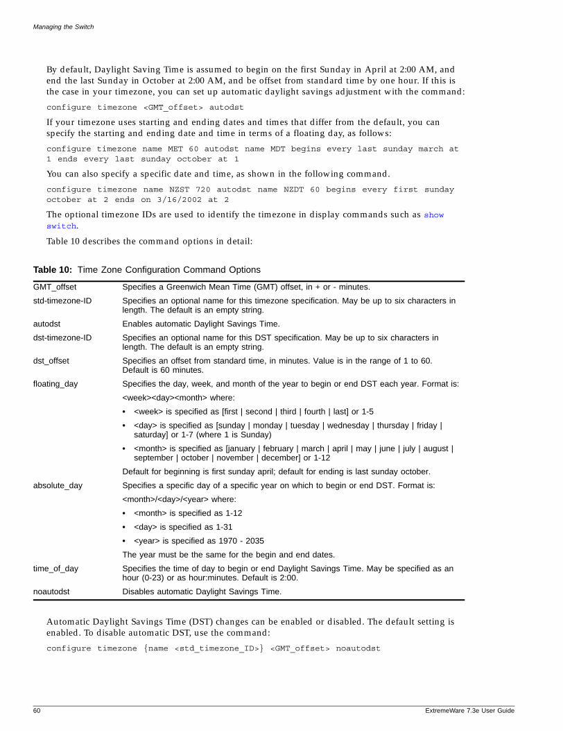
Managing the Switch
By default, Daylight Saving Time is assumed to begin on the first Sunday in April at 2:00 AM, and end the last Sunday in October at 2:00 AM, and be offset from standard time by one hour. If this is the case in your timezone, you can set up automatic daylight savings adjustment with the command:
configure timezone <GMT_offset> autodst
If your timezone uses starting and ending dates and times that differ from the default, you can specify the starting and ending date and time in terms of a floating day, as follows:
configure timezone name MET 60 autodst name MDT begins every last sunday march at 1 ends every last sunday october at 1
You can also specify a specific date and time, as shown in the following command.
configure timezone name NZST 720 autodst name NZDT 60 begins every first sunday october at 2 ends on 3/16/2002 at 2
The optional timezone IDs are used to identify the timezone in display commands such as show switch.
Table 10 describes the command options in detail:
Automatic Daylight Savings Time (DST) changes can be enabled or disabled. The default setting is enabled. To disable automatic DST, use the command:
configure timezone {name <std_timezone_ID>} <GMT_offset> noautodst
Table 10: Time Zone Configuration Command Options
GMT_offset Specifies a Greenwich Mean Time (GMT) offset, in + or - minutes.
std-timezone-ID Specifies an optional name for this timezone specification. May be up to six characters in length. The default is an empty string.
autodst Enables automatic Daylight Savings Time.
dst-timezone-ID Specifies an optional name for this DST specification. May be up to six characters in length. The default is an empty string.
dst_offset Specifies an offset from standard time, in minutes. Value is in the range of 1 to 60. Default is 60 minutes.
floating_day Specifies the day, week, and month of the year to begin or end DST each year. Format is:
<week><day><month> where:
• <week> is specified as [first | second | third | fourth | last] or 1-5
• <day> is specified as [sunday | monday | tuesday | wednesday | thursday | friday | saturday] or 1-7 (where 1 is Sunday)
• <month> is specified as [january | february | march | april | may | june | july | august | september | october | november | december] or 1-12
Default for beginning is first sunday april; default for ending is last sunday october.
absolute_day Specifies a specific day of a specific year on which to begin or end DST. Format is:
<month>/<day>/<year> where:
• <month> is specified as 1-12
• <day> is specified as 1-31
• <year> is specified as 1970 - 2035
The year must be the same for the begin and end dates.
time_of_day Specifies the time of day to begin or end Daylight Savings Time. May be specified as an hour (0-23) or as hour:minutes. Default is 2:00.
noautodst Disables automatic Daylight Savings Time.
60 ExtremeWare 7.3e User Guide
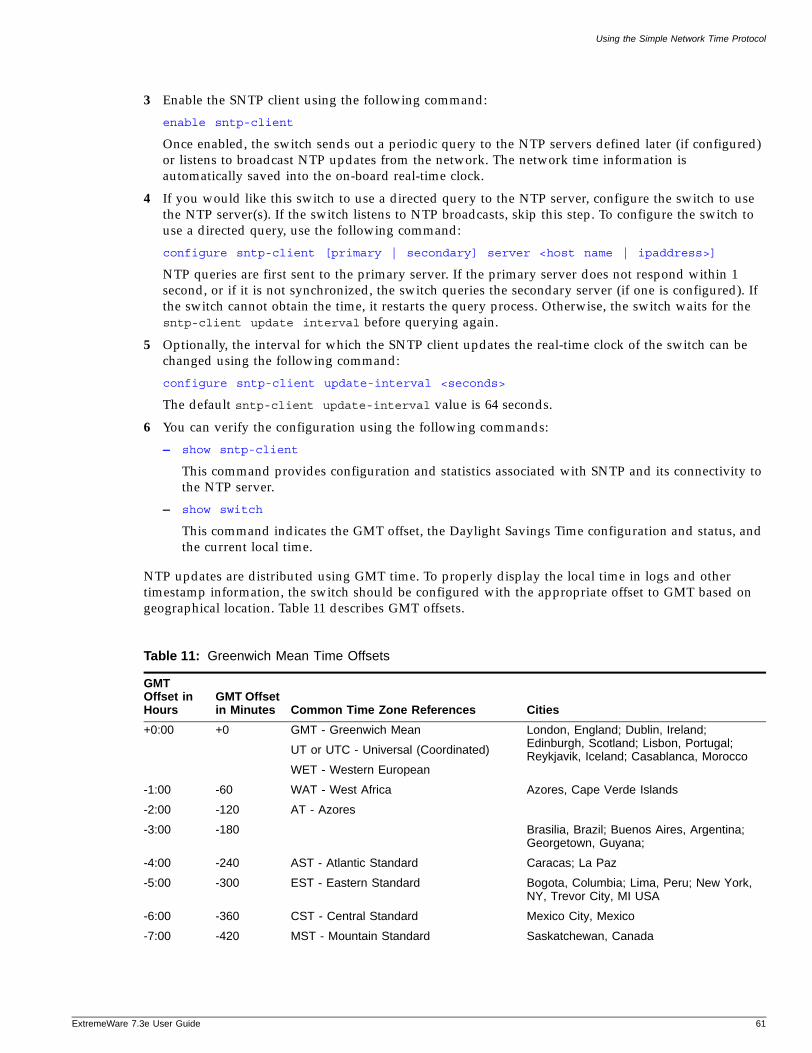
Using the Simple Network Time Protocol
ExtremeWare 7
3 Enable the SNTP client using the following command:
enable sntp-client
Once enabled, the switch sends out a periodic query to the NTP servers defined later (if configured) or listens to broadcast NTP updates from the network. The network time information is automatically saved into the on-board real-time clock.
4 If you would like this switch to use a directed query to the NTP server, configure the switch to use the NTP server(s). If the switch listens to NTP broadcasts, skip this step. To configure the switch to use a directed query, use the following command:
configure sntp-client [primary | secondary] server <host name | ipaddress>]
NTP queries are first sent to the primary server. If the primary server does not respond within 1 second, or if it is not synchronized, the switch queries the secondary server (if one is configured). If the switch cannot obtain the time, it restarts the query process. Otherwise, the switch waits for the sntp-client update interval before querying again.
5 Optionally, the interval for which the SNTP client updates the real-time clock of the switch can be changed using the following command:
configure sntp-client update-interval <seconds>
The default sntp-client update-interval value is 64 seconds.
6 You can verify the configuration using the following commands:
— show sntp-client
This command provides configuration and statistics associated with SNTP and its connectivity to the NTP server.
— show switch
This command indicates the GMT offset, the Daylight Savings Time configuration and status, and the current local time.
NTP updates are distributed using GMT time. To properly display the local time in logs and other timestamp information, the switch should be configured with the appropriate offset to GMT based on geographical location. Table 11 describes GMT offsets.
Table 11: Greenwich Mean Time Offsets
GMT Offset in Hours
GMT Offset in Minutes Common Time Zone References Cities
+0:00 +0 GMT - Greenwich Mean
UT or UTC - Universal (Coordinated)
WET - Western European
London, England; Dublin, Ireland; Edinburgh, Scotland; Lisbon, Portugal; Reykjavik, Iceland; Casablanca, Morocco
-1:00 -60 WAT - West Africa Azores, Cape Verde Islands
-2:00 -120 AT - Azores
-3:00 -180 Brasilia, Brazil; Buenos Aires, Argentina; Georgetown, Guyana;
-4:00 -240 AST - Atlantic Standard Caracas; La Paz
-5:00 -300 EST - Eastern Standard Bogota, Columbia; Lima, Peru; New York, NY, Trevor City, MI USA
-6:00 -360 CST - Central Standard Mexico City, Mexico
-7:00 -420 MST - Mountain Standard Saskatchewan, Canada
.3e User Guide 61
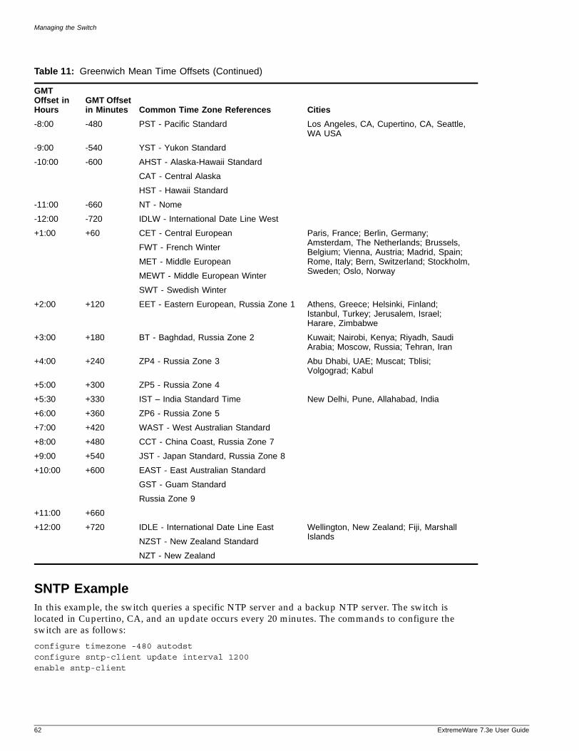
Managing the Switch
SNTP ExampleIn this example, the switch queries a specific NTP server and a backup NTP server. The switch is located in Cupertino, CA, and an update occurs every 20 minutes. The commands to configure the switch are as follows:
configure timezone -480 autodstconfigure sntp-client update interval 1200enable sntp-client
-8:00 -480 PST - Pacific Standard Los Angeles, CA, Cupertino, CA, Seattle, WA USA
-9:00 -540 YST - Yukon Standard
-10:00 -600 AHST - Alaska-Hawaii Standard
CAT - Central Alaska
HST - Hawaii Standard
-11:00 -660 NT - Nome
-12:00 -720 IDLW - International Date Line West
+1:00 +60 CET - Central European
FWT - French Winter
MET - Middle European
MEWT - Middle European Winter
SWT - Swedish Winter
Paris, France; Berlin, Germany; Amsterdam, The Netherlands; Brussels, Belgium; Vienna, Austria; Madrid, Spain; Rome, Italy; Bern, Switzerland; Stockholm, Sweden; Oslo, Norway
+2:00 +120 EET - Eastern European, Russia Zone 1 Athens, Greece; Helsinki, Finland; Istanbul, Turkey; Jerusalem, Israel; Harare, Zimbabwe
+3:00 +180 BT - Baghdad, Russia Zone 2 Kuwait; Nairobi, Kenya; Riyadh, Saudi Arabia; Moscow, Russia; Tehran, Iran
+4:00 +240 ZP4 - Russia Zone 3 Abu Dhabi, UAE; Muscat; Tblisi; Volgograd; Kabul
+5:00 +300 ZP5 - Russia Zone 4
+5:30 +330 IST – India Standard Time New Delhi, Pune, Allahabad, India
+6:00 +360 ZP6 - Russia Zone 5
+7:00 +420 WAST - West Australian Standard
+8:00 +480 CCT - China Coast, Russia Zone 7
+9:00 +540 JST - Japan Standard, Russia Zone 8
+10:00 +600 EAST - East Australian Standard
GST - Guam Standard
Russia Zone 9
+11:00 +660
+12:00 +720 IDLE - International Date Line East
NZST - New Zealand Standard
NZT - New Zealand
Wellington, New Zealand; Fiji, Marshall Islands
Table 11: Greenwich Mean Time Offsets (Continued)
GMT Offset in Hours
GMT Offset in Minutes Common Time Zone References Cities
62 ExtremeWare 7.3e User Guide
Using EAPOL Flooding
ExtremeWare 7
configure sntp-client primary server 10.0.1.1configure sntp-client secondary server 10.0.1.2
Using EAPOL Flooding
Port-based Network Access Control (IEEE 802.1x) uses Extensible Authentication Protocol (EAP) as the underlying mechanism for transferring information between the three network entities engaged in the IEEE 802.1x port authentication access control process: the supplicant, the authenticator, and the authenticating server. The encapsulating mechanism used for communication between the supplicant and the authenticator is referred to as EAP Over LANs, or EAPOL.
By default (per IEEE 802.1D), Summit 200, Summit 300, and Summit 400 series switches do not forward EAPOL frames. Also, if network login is enabled, EAPOL flooding cannot be enabled. However, under certain conditions, you might opt to change this behavior to support an upstream central authenticator by enabling the switch to flood the EAPOL frame on the VLAN associated with the ingress port.
The following example enables EAPOL frame flooding on a Summit 200, Summit 300, or Summit 400 series switch that does not have Network login enabled:
enable eapol-flooding
When EAPOL flooding is enabled on the switch, you can verify that status by using the command:
show configuration
The following example disables EAPOL frame flooding on a Summit 200, Summit 300, or Summit 400 series switch:
disable eapol-flooding
You can verify the current EAPOL flooding state by using the command:
show eapol-flooding
.3e User Guide 63

Managing the Switch
64 ExtremeWare 7.3e User Guide
4 Configuring Ports
ExtremeWare 7
This chapter covers the following topics:
• Port Numbering on page 65
• Enabling and Disabling Switch Ports on page 66
• Configuring Switch Port Speed and Duplex Setting on page 66
• Jumbo Frames—Summit 400 Switch Only on page 68
• Load Sharing on the Switch on page 71
• Switch Port-Mirroring on page 75
• Extreme Discovery Protocol on page 76
Port Numbering
Summit 200, Summit 300-24, and Summit 400 SwitchesPorts on the Summit 200, Summit 300-24 and Summit 400 switches are simply noted by their physical port number. When entering commands that require you to enter one or more port numbers, you can enter the the port number separated by a comma. You can also enter a range of numbers, for example:
port 1-3,6,8
Summit 300-48 SwitchOn a Summit 300-48 switch, the port number is a combination of the slot number and the port number. The nomenclature for the port number is as follows:
slot:port
You can use wildcard combinations (*) to specify multiple slot and port combinations. The following wildcard combinations are allowed:
• slot:* — Specifies all ports on a particular I/O module.
• slot:x-slot:y — Specifies a contiguous series of ports on a particular I/O module.
• slota:x-slotb:y — Specifies a contiguous series of ports that begin on one I/O module and end on another I/O module.
.3e User Guide 65
Configuring Ports
Enabling and Disabling Switch Ports
By default, all ports are enabled. To enable or disable one or more ports, use the following command:
enable ports [<portlist> | all | {vlan} <vlan name>]
disable ports [<portlist> | all |{vlan} <vlan name>]
For example, to disable slot 7, ports 3, 5, and 12 through 15 on a modular switch, use the following command:
disable ports 7:3,7:5,7:12-7:15
Likewise, to disable ports 3, 5, and 12 through 15 on a stand-alone switch, use the following command:
disable ports 3,5,12-15
Even though a port is disabled, the link remains enabled for diagnostic purposes. Disabling of load sharing ports is not supported.
Configuring Switch Port Speed and Duplex Setting
When configuring the speed and duplex setting for a port, autonegotiation plays a significant role. By default, the switch is configured to use autonegotiation to determine the port speed and duplex setting for each port.
10BASE-T and 100BASE-TX ports can connect to either 10BASE-T or 100BASE-T networks. By default, the ports autonegotiate port speed. You can also configure each port for a particular speed (either 10 Mbps or 100 Mbps). Gigabit Ethernet ports are statically set to 1 Gbps, and their speed cannot be modified.
If you plan on running the copper ports at 1000 Mbps, it is recommended that you keep autonegotiation on. For ports running at slower speeds, you can manually configure the speed of 10/100/1000 Mbps ports and disable autonegotiation.
To configure port speed and duplex setting, use the following command:
configure ports [<portlist> | all | mgmt] auto off {speed [10 | 100 | 1000]} duplex [half | full]
The mgmt option is only available on the Summit 400.
To configure the system to autonegotiate, use the following command:
configure ports [<portlist> | mgmt | all] auto on
The mgmt option is only available on the Summit 400.
Gigabit Ethernet fiber ports only run at full-duplex but you must specify the duplex setting. The 10/100/1000 copper ports, however, can be either be configured for half-duplex or full-duplex operation. These 10/100/1000 Mbps ports are supported only through autonegotiation.
Summit 200 and Summit 300-24 only. Flow control is supported only on Gigabit Ethernet ports. It is enabled or disabled as part of autonegotiation. If autonegotiation is set to off, flow control is disabled. When autonegotiation is turned on, flow control is enabled.
66 ExtremeWare 7.3e User Guide
Configuring Switch Port Speed and Duplex Setting
ExtremeWare 7
Summit 400 only. The Summit 400-48t has four 1000 Mbps fiber and 48 copper 10/100/1000 Mbps ports. All of the fiber ports can be configured for automatic failover using the first four copper ports. These ports are called combination ports because either the fiber port or the copper port is active, but they are never active concurrently. For a description of cabling for combination ports, see “Uplink Redundancy” on page 27. For information on configuring combination ports, see “Configuring Automatic Failover for Combination Ports” on page 79. If you plan to use the automatic failover feature, ensure that port settings are set correctly for autonegotiation. Summit 400 ports do not advertise or support flow control frames.
Turning Off Autonegotiation for a Gigabit Ethernet Port
In certain interoperability situations, you may need to turn autonegotiation off on a Gigabit Ethernet port. Even though a Gigabit Ethernet port runs only at full duplex, you must specify the duplex setting.
NOTE
1000BASE-T ports support only autonegotiation.
The following example turns autonegotiation off for port 4 (a combination port):
configure ports 4 auto off duplex full speed 1000
Turning Off Autopolarity Detection for an Ethernet Port—Summit 200 and Summit 300-24 Switches OnlyThe autopolarity feature on the Summit 200 and Summit 300-24 switches allows the system to detect and respond to the Ethernet cable type (straight-through vs. crossover cable) used to make the connection to the switch port. When the autopolarity feature is enabled, the system causes the Ethernet link to come up regardless of the cable type connected to the port. When the autopolarity feature is disabled, the link will come up only when a crossover cable is connected to the port. The autopolarity feature is supported only on the 10BASE-T and 100BASE-TX switch ports, and enabled by default.
To disable or enable autopolarity detection, use the following command:
configure ports [<portlist> | all] auto-polarity [off | on]
where the following is true:
• portlist—Specifies one or more ports on the switch
• all—Specifies all of the ports on the switch
• off—Disables the autopolarity detection feature on the specified ports
• on—Enables the autopolarity detection feature on the specified ports
Under certain conditions, you might opt to turn autopolarity off on one or more 10BASE-T and 100BASE-TX ports. The following example turns autopolarity off for ports 3-5 either on a Summit 200 or Summit 300-24 switch:
configure ports 3-5 auto-polarity off
.3e User Guide 67
Configuring Ports
NOTE
If you attempt to invoke this command on a Gigabit Ethernet switch port, the system displays a message indicating that the specified port is not supported by this feature.
When autopolarity is disabled on one or more Ethernet ports, you can verify that status by using the command:
show configuration
This command lists the ports for that have the feature disabled.
You can also verify the current autopolarity status by using the command:
show ports {mgmt | <portlist>| vlan <vlan name>} info {detail}
The mgmt option is only available on the Summit 400 switch.
Configuring Interpacket Gap for Gigabit Ethernet Ports—Summit 400 Switch OnlyYou can configure the Interpacket Gap for 1 or 10 Gigabit Ethernet ports. The Interpacket Gap, sometimes referred to as the Interframe Gap, is the transmit packet byte-time delay between successive data packets mandated by the IEEE for Ethernet networks. Byte-time is the amount of time it takes to transmit one byte on the link at the specified or negotiated link speed. The configured Interpacket Gap value has no effect on received packets. The default value is 12. The minimum and maximum allowed values range between 12 and 1023.
The standard effective Interpacket Gap for Gigabit Ethernet interfaces ranges between 12 and 1023. Some vendors' 10 Gigabit Ethernet interfaces drop packets when packets are transmitted using a value of 12. Thus, by increasing the Interpacket Gap, packet transmission is slowed and packet loss can be minimized or prevented. The Interpacket Gap value need not be modified when interconnecting Extreme Networks switches over 10 Gigabit Ethernet links. Use the following command to modify the Interpacket Gap:
configure port <port> interpacket-gap <byte_time>
Jumbo Frames—Summit 400 Switch Only
Jumbo frames are Ethernet frames that are larger than 1522 bytes, including four bytes used for the cyclic redundancy check (CRC). Extreme products support switching and routing of jumbo frames at wire-speed on all ports.
Jumbo frames are used between endstations that support larger frame sizes for more efficient transfers of bulk data. Both endstations involved in the transfer must be capable of supporting jumbo frames. The switch only performs IP fragmentation, or participates in maximum transmission unit (MTU) negotiation on behalf of devices that support jumbo frames.
68 ExtremeWare 7.3e User Guide
Jumbo Frames—Summit 400 Switch Only
ExtremeWare 7
Enabling Jumbo FramesTo enable jumbo frame support, enable jumbo frames on the desired ports. To set the maximum jumbo frame size, use the following command:
configure jumbo-frame size <number>
The jumbo frame size range is 1523 to 9216. This value describes the maximum size of the frame in transit (on the wire), and includes 4 bytes of CRC plus another 4 bytes if 802.1Q tagging is being used.
Set the MTU size for the VLAN, using the following command:
configure ip-mtu <number> vlan <vlan name>
The IP MTU default is 1500. The range is 1500-9194.
Next, enable support on the physical ports that will carry jumbo frames using the following command:
enable jumbo-frame ports [<portlist> | all]
NOTE
Some network interface cards (NICs) have a configured maximum MTU size that does not include the additional 4 bytes of CRC. Ensure that the NIC maximum MTU size is at or below the maximum MTU size configured on the switch. Frames that are larger than the MTU size configured on the switch are dropped at the ingress port.
Jumbo Frames ExampleThe following example create two VLANs sw1 and sw2. It adds port 12 to sw1 and port 13 to sw2. It configures port 12 and 13 for jumbo frames up to 9216 bytes (including CRC). It also configures VLANs sw1 and sw2 to accept IP packets up to 9194 bytes.
* Summit400-48t:48 # create vlan sw1* Summit400-48t:49 # create vlan sw2* Summit400-48t:50 # configure vlan sw1 add port 12* Summit400-48t:51 # configure vlan sw2 add port 13* Summit400-48t:52 # configure jumbo-frame size 9216* Summit400-48t:53 # enable jumbo-frame ports 12,13* Summit400-48t:54 # configure ip-mtu 9194 vlan vlansw1* Summit400-48t:55 # configure ip-mtu 9194 vlan vlansw2
Path MTU DiscoveryUsing path MTU discovery, a source host assumes that the path MTU is the MTU of the first hop (which is known). The host sends all datagrams on that path with the “don’t fragment” (DF) bit set, which restricts fragmentation. If any of the datagrams must be fragmented by an Extreme switch along the path, the Extreme switch discards the datagrams and returns an ICMP Destination Unreachable message to the sending host, with a code meaning “fragmentation needed and DF set”. When the source host receives the message (sometimes called a “Datagram Too Big” message), the source host reduces its assumed path MTU and retransmits the datagrams.
The path MTU discovery process ends when one of the following is true:
• The source host sets the path MTU low enough that its datagrams can be delivered without fragmentation.
.3e User Guide 69
Configuring Ports
• The source host does not set the DF bit in the datagram headers.
If it is willing to have datagrams fragmented, a source host can choose not to set the DF bit in datagram headers. Normally, the host continues to set DF in all datagrams, so that if the route changes and the new path MTU is lower, the host can perform path MTU discovery again.
IP Fragmentation with Jumbo FramesExtremeWare supports the fragmenting of IP packets. If an IP packet originates in a local network that allows large packets and those packets traverse a network that limits packets to a smaller size, the packets are fragmented instead of discarded.
This feature is designed to be used in conjunction with jumbo frames. Frames that are fragmented are not processed at wire-speed within the switch fabric.
NOTE
Jumbo frame-to-jumbo frame fragmentation is not supported. Only jumbo frame-to-normal frame fragmentation is supported.
To configure VLANs for IP fragmentation, follow these steps:
1 Enable jumbo frames on the incoming port.
2 Add the port to a VLAN.
3 Assign an IP address to the VLAN.
4 Enable ipforwarding on the VLAN.
5 Set the MTU size for the VLAN, using the following command:
configure ip-mtu <number> vlan <vlan name>
The ip-mtu value can be 1500 - 9194, with 1500 the default.
NOTE
To set the MTU size greater than 1500, all ports in the VLAN must have jumbo frames enabled.
IP Fragmentation within a VLANExtremeWare supports IP fragmentation within a VLAN. This feature does not require you to configure the MTU size. To use IP fragmentation within a VLAN, follow these steps:
1 Enable jumbo frames on the incoming port.
2 Add the port to a VLAN.
3 Assign an IP address to the VLAN.
4 Enable ipforwarding on the VLAN.
If you leave the MTU size configured to the default value, when you enable jumbo frame support on a port on the VLAN you receive a warning that the ip-mtu size for the VLAN is not set at maximum jumbo frame size. You can ignore this warning if you want IP fragmentation within the VLAN, only.
70 ExtremeWare 7.3e User Guide
Load Sharing on the Switch
ExtremeWare 7
However, if you do not use jumbo frames, IP fragmentation can only be used for traffic that stays within the same VLAN. To use IP fragmentation for traffic that is set to other VLANs, you must configure all ports in the VLAN for jumbo frame support.
Load Sharing on the Switch
Load sharing allows you to increase bandwidth and availability by using a group of ports to carry traffic in parallel between switches. Load sharing allows the switch to use multiple ports as a single logical port. For example, VLANs see the load-sharing group as a single logical port. Most load-sharing algorithms guarantee packet sequencing between clients.
If a port in a load-sharing group fails, traffic is redistributed to the remaining ports in the load-sharing group. If the failed port becomes active again, traffic is redistributed to include that port.
NOTE
Load sharing must be enabled on both ends of the link or a network loop may result. The load-sharing types algorithms do not need to be the same on both ends.
Dynamic Versus Static Load SharingThe two broad categories of load sharing supported on Extreme Network switches are dynamic load sharing and static load sharing:
• Dynamic load sharing—A grouping of ports that use IEEE 802.3ad load sharing to dynamically determine if load sharing is possible, and automatically configure load sharing when possible. Uses Link Aggregation Control Protocol (LACP), part of the IEEE 802.3ad standard, to allow the switch to dynamically reconfigure the sharing groups. The group is only enabled when LACP detects that the other side is also using LACP, and wants these ports to be in a group.
• Static load sharing—A grouping of ports specifically configured to load share. The switch ports at each end must be configured as part of a load-sharing group. Additionally, you can choose the load-sharing algorithm used by the group. This feature is supported between Extreme Networks switches only, but may be compatible with third-party trunking or link-aggregation algorithms. Check with an Extreme Networks technical representative for more information.
Load-Sharing AlgorithmSummit “e” series switches support only an address-based load-sharing algorithm as the distribution technique to determine the output port selection. Algorithm selection is not intended for use in predictive traffic engineering. The algorithm uses addressing information to determine which physical port in the load-sharing group to use for forwarding traffic out of the switch. Addressing information is based on the packet protocol, as follows:
— IP packets—Uses the source and destination MAC and IP addresses.
— All other packets—Uses the source and destination MAC address.
Configured IP Address-Based Load Sharing
When you configure load sharing, the switch examines a specific place in the packet to determine which egress port to use for forwarding traffic.
.3e User Guide 71
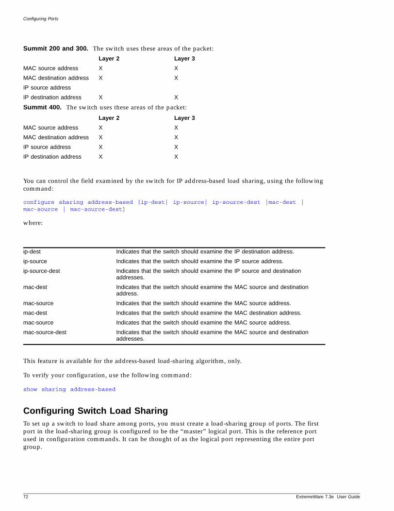
Configuring Ports
Summit 200 and 300. The switch uses these areas of the packet:
Summit 400. The switch uses these areas of the packet:
You can control the field examined by the switch for IP address-based load sharing, using the following command:
configure sharing address-based [ip-dest| ip-source| ip-source-dest |mac-dest | mac-source | mac-source-dest]
where:
This feature is available for the address-based load-sharing algorithm, only.
To verify your configuration, use the following command:
show sharing address-based
Configuring Switch Load SharingTo set up a switch to load share among ports, you must create a load-sharing group of ports. The first port in the load-sharing group is configured to be the “master” logical port. This is the reference port used in configuration commands. It can be thought of as the logical port representing the entire port group.
Layer 2 Layer 3
MAC source address X X
MAC destination address X X
IP source address
IP destination address X X
Layer 2 Layer 3
MAC source address X X
MAC destination address X X
IP source address X X
IP destination address X X
ip-dest Indicates that the switch should examine the IP destination address.
ip-source Indicates that the switch should examine the IP source address.
ip-source-dest Indicates that the switch should examine the IP source and destination addresses.
mac-dest Indicates that the switch should examine the MAC source and destination address.
mac-source Indicates that the switch should examine the MAC source address.
mac-dest Indicates that the switch should examine the MAC destination address.
mac-source Indicates that the switch should examine the MAC source address.
mac-source-dest Indicates that the switch should examine the MAC source and destination addresses.
72 ExtremeWare 7.3e User Guide
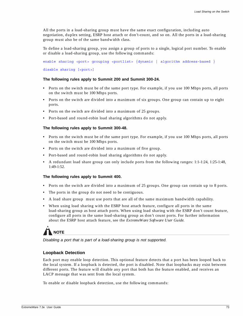
Load Sharing on the Switch
ExtremeWare 7
All the ports in a load-sharing group must have the same exact configuration, including auto negotiation, duplex setting, ESRP host attach or don’t-count, and so on. All the ports in a load-sharing group must also be of the same bandwidth class.
To define a load-sharing group, you assign a group of ports to a single, logical port number. To enable or disable a load-sharing group, use the following commands:
enable sharing <port> grouping <portlist> {dynamic | algorithm address-based }
disable sharing [<port>]
The following rules apply to Summit 200 and Summit 300-24.
• Ports on the switch must be of the same port type. For example, if you use 100 Mbps ports, all ports on the switch must be 100 Mbps ports.
• Ports on the switch are divided into a maximum of six groups. One group can contain up to eight ports.
• Ports on the switch are divided into a maximum of 25 groups.
• Port-based and round-robin load sharing algorithms do not apply.
The following rules apply to Summit 300-48.
• Ports on the switch must be of the same port type. For example, if you use 100 Mbps ports, all ports on the switch must be 100 Mbps ports.
• Ports on the switch are divided into a maximum of five group.
• Port-based and round-robin load sharing algorithms do not apply.
• A redundant load share group can only include ports from the following ranges: 1:1-1:24, 1:25-1:48, 1:49-1:52.
The following rules apply to Summit 400.
• Ports on the switch are divided into a maximum of 25 groups. One group can contain up to 8 ports.
• The ports in the group do not need to be contiguous.
• A load share group must use ports that are all of the same maximum bandwidth capability.
• When using load sharing with the ESRP host attach feature, configure all ports in the same load-sharing group as host attach ports. When using load sharing with the ESRP don’t count feature, configure all ports in the same load-sharing group as don’t count ports. For further information about the ESRP host attach feature, see the ExtremeWare Software User Guide.
NOTE
Disabling a port that is part of a load-sharing group is not supported.
Loopback Detection
Each port may enable loop detection. This optional feature detects that a port has been looped back to the local system. If a loopback is detected, the port is disabled. Note that loopbacks may exist between different ports. The feature will disable any port that both has the feature enabled, and receives an LACP message that was sent from the local system.
To enable or disable loopback detection, use the following commands:
.3e User Guide 73
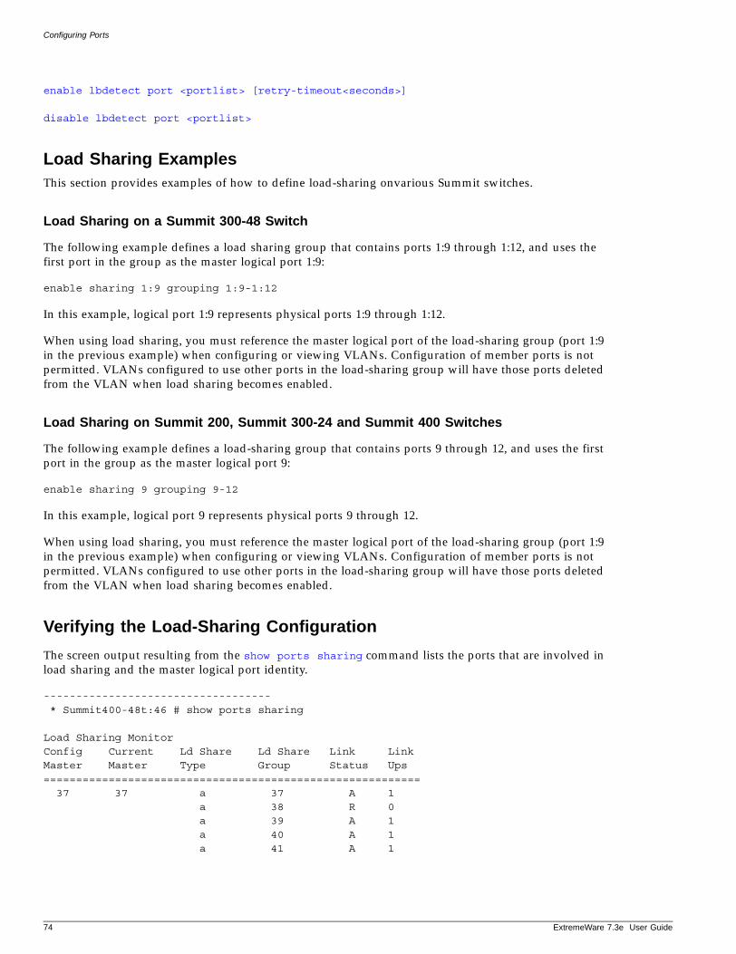
Configuring Ports
enable lbdetect port <portlist> [retry-timeout<seconds>]
disable lbdetect port <portlist>
Load Sharing ExamplesThis section provides examples of how to define load-sharing onvarious Summit switches.
Load Sharing on a Summit 300-48 Switch
The following example defines a load sharing group that contains ports 1:9 through 1:12, and uses the first port in the group as the master logical port 1:9:
enable sharing 1:9 grouping 1:9-1:12
In this example, logical port 1:9 represents physical ports 1:9 through 1:12.
When using load sharing, you must reference the master logical port of the load-sharing group (port 1:9 in the previous example) when configuring or viewing VLANs. Configuration of member ports is not permitted. VLANs configured to use other ports in the load-sharing group will have those ports deleted from the VLAN when load sharing becomes enabled.
Load Sharing on Summit 200, Summit 300-24 and Summit 400 Switches
The following example defines a load-sharing group that contains ports 9 through 12, and uses the first port in the group as the master logical port 9:
enable sharing 9 grouping 9-12
In this example, logical port 9 represents physical ports 9 through 12.
When using load sharing, you must reference the master logical port of the load-sharing group (port 1:9 in the previous example) when configuring or viewing VLANs. Configuration of member ports is not permitted. VLANs configured to use other ports in the load-sharing group will have those ports deleted from the VLAN when load sharing becomes enabled.
Verifying the Load-Sharing Configuration
The screen output resulting from the show ports sharing command lists the ports that are involved in load sharing and the master logical port identity.
----------------------------------- * Summit400-48t:46 # show ports sharing
Load Sharing MonitorConfig Current Ld Share Ld Share Link LinkMaster Master Type Group Status Ups========================================================== 37 37 a 37 A 1 a 38 R 0 a 39 A 1 a 40 A 1 a 41 A 1
74 ExtremeWare 7.3e User Guide
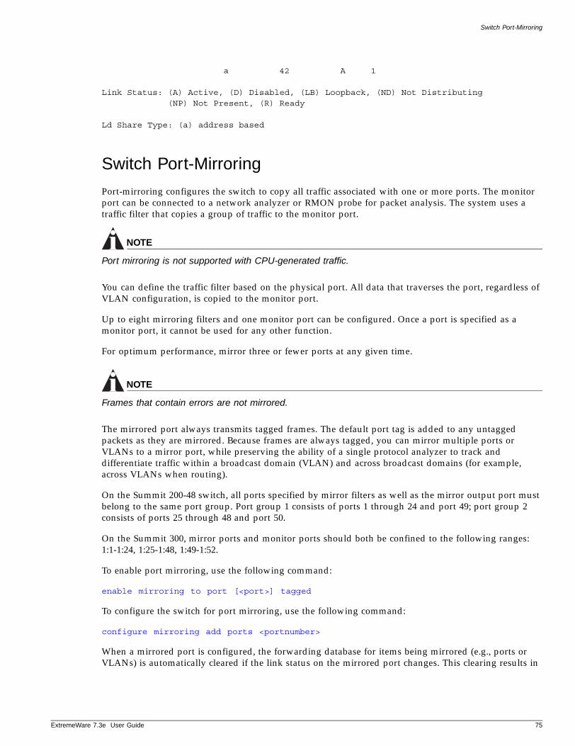
Switch Port-Mirroring
ExtremeWare 7
a 42 A 1
Link Status: (A) Active, (D) Disabled, (LB) Loopback, (ND) Not Distributing (NP) Not Present, (R) Ready
Ld Share Type: (a) address based
Switch Port-Mirroring
Port-mirroring configures the switch to copy all traffic associated with one or more ports. The monitor port can be connected to a network analyzer or RMON probe for packet analysis. The system uses a traffic filter that copies a group of traffic to the monitor port.
NOTE
Port mirroring is not supported with CPU-generated traffic.
You can define the traffic filter based on the physical port. All data that traverses the port, regardless of VLAN configuration, is copied to the monitor port.
Up to eight mirroring filters and one monitor port can be configured. Once a port is specified as a monitor port, it cannot be used for any other function.
For optimum performance, mirror three or fewer ports at any given time.
NOTE
Frames that contain errors are not mirrored.
The mirrored port always transmits tagged frames. The default port tag is added to any untagged packets as they are mirrored. Because frames are always tagged, you can mirror multiple ports or VLANs to a mirror port, while preserving the ability of a single protocol analyzer to track and differentiate traffic within a broadcast domain (VLAN) and across broadcast domains (for example, across VLANs when routing).
On the Summit 200-48 switch, all ports specified by mirror filters as well as the mirror output port must belong to the same port group. Port group 1 consists of ports 1 through 24 and port 49; port group 2 consists of ports 25 through 48 and port 50.
On the Summit 300, mirror ports and monitor ports should both be confined to the following ranges: 1:1-1:24, 1:25-1:48, 1:49-1:52.
To enable port mirroring, use the following command:
enable mirroring to port [<port>] tagged
To configure the switch for port mirroring, use the following command:
configure mirroring add ports <portnumber>
When a mirrored port is configured, the forwarding database for items being mirrored (e.g., ports or VLANs) is automatically cleared if the link status on the mirrored port changes. This clearing results in
.3e User Guide 75
Configuring Ports
some temporary flooding until the normal learning process completes. Removing or inserting a probe device into the mirror port may appear to cause flooding, but this temporary condition is normal. The same packet cannot be mirrored twice. The mirrored port output of layer 3 forwarding shows the packet state from the switch to the next hop.
Port-Mirroring ExamplesThis section provides port-mirroring examples on various Summit switches.
Summit 300 Example
The following example selects port 1:3 as the mirror port and sends all traffic coming into or out of the switch on port 1:1 to the mirror port:
enable mirroring to port 1:3 taggedconfig mirroring add port 1:1
Summit 200 and 400 Example
The following example selects port 3 as the mirror port and sends all traffic coming into or out of the switch on port 1 to the mirror port:
enable mirroring to port 3 taggedconfigure mirroring add port 1
Extreme Discovery Protocol
The Extreme Discovery Protocol (EDP) is used to gather information about neighbor Extreme Networks switches. EDP is used by the switches to exchange topology information. EDP is also used by the Extreme Standby Router Protocol (ESRP), described in Chapter 15. Information communicated using EDP includes:
• Switch MAC address (switch ID).
• Switch software version information.
• Switch IP address.
• Switch VLAN-IP information.
• Switch port number.
CAUTION
EDP is enabled on all ports by default. With EDP enabled, none of the wireless ports will be able to participate in the Access Adapt protocol which is based on EDP. For more information about wireless ports, see Chapter 6.
To disable EDP on one or more ports, use the following command:
disable edp ports [<portlist> | all]
To enable EDP on specified ports, use the following command:
enable edp ports [<portlist> | all]
76 ExtremeWare 7.3e User Guide
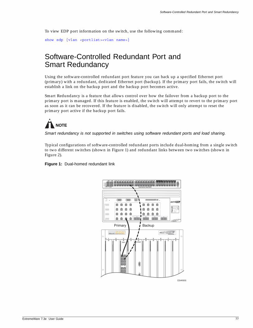
Software-Controlled Redundant Port and Smart Redundancy
ExtremeWare 7
To view EDP port information on the switch, use the following command:
show edp {vlan <portlist><vlan name>}
Software-Controlled Redundant Port and Smart Redundancy
Using the software-controlled redundant port feature you can back up a specified Ethernet port (primary) with a redundant, dedicated Ethernet port (backup). If the primary port fails, the switch will establish a link on the backup port and the backup port becomes active.
Smart Redundancy is a feature that allows control over how the failover from a backup port to the primary port is managed. If this feature is enabled, the switch will attempt to revert to the primary port as soon as it can be recovered. If the feature is disabled, the switch will only attempt to reset the primary port active if the backup port fails.
NOTE
Smart redundancy is not supported in switches using software redundant ports and load sharing.
Typical configurations of software-controlled redundant ports include dual-homing from a single switch to two different switches (shown in Figure 1) and redundant links between two switches (shown in Figure 2).
Figure 1: Dual-homed redundant link
ES4K003
1 2 3 4 A B 5 6 7 8
Primary Backup
4
1
20
17
5 21
29 30 31 32
4
12
20
5
13
21
6
14
22
7
15
23
8
16
24
28
3
11
19
27
2
10
18
26
1
9
17
25
.3e User Guide 77
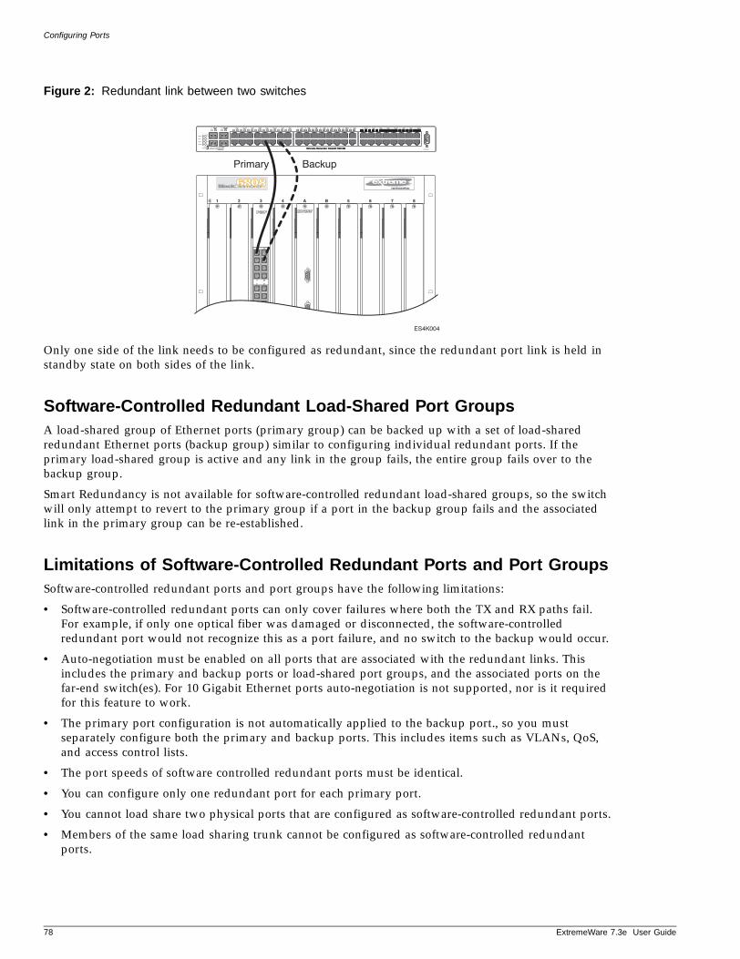
Configuring Ports
Figure 2: Redundant link between two switches
Only one side of the link needs to be configured as redundant, since the redundant port link is held in standby state on both sides of the link.
Software-Controlled Redundant Load-Shared Port GroupsA load-shared group of Ethernet ports (primary group) can be backed up with a set of load-shared redundant Ethernet ports (backup group) similar to configuring individual redundant ports. If the primary load-shared group is active and any link in the group fails, the entire group fails over to the backup group.
Smart Redundancy is not available for software-controlled redundant load-shared groups, so the switch will only attempt to revert to the primary group if a port in the backup group fails and the associated link in the primary group can be re-established.
Limitations of Software-Controlled Redundant Ports and Port GroupsSoftware-controlled redundant ports and port groups have the following limitations:
• Software-controlled redundant ports can only cover failures where both the TX and RX paths fail. For example, if only one optical fiber was damaged or disconnected, the software-controlled redundant port would not recognize this as a port failure, and no switch to the backup would occur.
• Auto-negotiation must be enabled on all ports that are associated with the redundant links. This includes the primary and backup ports or load-shared port groups, and the associated ports on the far-end switch(es). For 10 Gigabit Ethernet ports auto-negotiation is not supported, nor is it required for this feature to work.
• The primary port configuration is not automatically applied to the backup port., so you must separately configure both the primary and backup ports. This includes items such as VLANs, QoS, and access control lists.
• The port speeds of software controlled redundant ports must be identical.
• You can configure only one redundant port for each primary port.
• You cannot load share two physical ports that are configured as software-controlled redundant ports.
• Members of the same load sharing trunk cannot be configured as software-controlled redundant ports.
1 2 3 4 A B 5 6 7 8
ES4K004
Primary Backup
4
1
20
17
5 21
78 ExtremeWare 7.3e User Guide
Configuring Automatic Failover for Combination Ports
ExtremeWare 7
• Dual-homing of load-shared, software-controlled redundant port groups is not supported.
Configuring Software-Controlled Redundant PortsWhen provisioning software-controlled redundant ports, configure only one side of the link as redundant. In Figure 1 and Figure 2 only the ports on the lower switch would be configured as redundant.
In order to enable the software-controlled redundant port feature the primary and backup ports must be set up identically. This will include VLAN configuration, QoS settings, and any Access Control List configurations. Finally, all ports (primary, secondary, and both of the associated far-end ports) must be configured to have auto-negotiation enabled.
To configure a software-controlled redundant port, use the following command:
configure ports [<portlist> | <portid>] redundant [<portlist> | <portid>]
The first port specified is the primary port. The second port specified is the redundant port.
To unconfigure a software-controlled redundant port, use the following command:
unconfigure ports [<portlist> | <port id>] redundant
To configure the switch for the Smart Redundancy feature, use the following command:
enable smartredundancy <portlist>
To disable the Smart Redundancy feature, use the following command:
disable smartredundancy [<portlist>]
Configuring Automatic Failover for Combination Ports
All Summit “e” series allow for automatic failover on combination ports. However, the implementation of the failover behavior varies somewhat by Summit model.
Summit 200 Automatic FailoverThe Summit 200 supports an automatic failover from an active fiber port to a copper back up or from an active copper port to a fiber port. If one of the uplink connections fails, then the Summit 200 uplink connection automatically fails over to the second connection. The preferred medium is fiber and cannot be configured.
On the Summit 200-24, ports 25 and 26 are the Gigabit Ethernet ports that have the redundant PHY interfaces. On the Summit 200-48, it is ports 49 and 50. Each port has one mini-GBIC and 1000BASE-T connection.
To set up a redundant link on either port 25 or on port 49, connect the active fibre and 1000BASE-T links to both the RJ-45 and mini-GBIC interfaces of that port.
Summit 200-24 Switch Uplink Redundancy
Gigabit Ethernet uplink redundancy on the Summit 200-24 switch follows these rules:
• Ports 25 and 26 are Gigabit Ethernet ports that have redundant PHY interfaces, one mini-GBIC and one 1000BASE-T connection for each port.
.3e User Guide 79
Configuring Ports
• Each of the uplink Gigabit Ethernet ports (25 and 26) can use either the mini-GBIC or the 1000BASE-T interface, but not both simultaneously.
• Only one interface on each port can be active at a time. For example, on port 25, with both the mini-GBIC and 1000BASE-T interfaces connected, only one interface can be activated. The other is inactive. If both interfaces are connected, the switch defaults to the fiber interface (mini-GBIC) and deactivates the 1000BASE-T interface.
• If only one interface is connected, the switch activates the connected interface.
• To set up a redundant link on port 25, connect the active fibre and 1000BASE-T links to both the RJ-45 and mini-GBIC interfaces of port 25. The switch defaults to the fiber link. If the fiber link fails during operation, the switch automatically activates the redundant 1000BASE-T link.
Summit 200-48 Switch Uplink Redundancy
Gigabit Ethernet uplink redundancy on the Summit 200-48 switch follows these rules:
• Ports 49 and 50 are Gigabit Ethernet ports that have redundant PHY interfaces, one mini-GBIC and one 1000BASE-T connection for each port.
• Each of the uplink Gigabit Ethernet ports (49 and 50) can use either the mini-GBIC or the1000BASE-T interface, but not both simultaneously.
• Only one interface on each port can be active at a time. For example, on port 49, with both the mini-GBIC and 1000BASE-T interfaces connected, only one interface can be activated. The other is inactive. If both interfaces are connected, the switch defaults to the fiber interface (mini-GBIC) and deactivates the 1000BASE-T interface.
• If only one interface is connected, the switch activates the connected interface.
• To set up a redundant link on port 49, connect the active fibre and 1000BASE-T links to both the RJ-45 and mini-GBIC interfaces of port 49. The switch defaults to the fiber link. If the fiber link fails during operation, the switch automatically activates the redundant 1000BASE-T link.
Summit 300 Automatic Failover
The Summit 300 switches provides dual-media support on GigE ports. On the Summit 300-24, ports 24 and 25 are Gigabit Ethernet ports that have redundant PHY interfaces, one mini-GBIC and one 1000BASE-T connection for each port. On the Summit 300-48 it is ports 49-52 that are dual-mode redundant ports. Only one media type (fiber or copper) can be active at the same time. The Summit models follow the same failover behavior as the Summit 400. For details of that behavior, see “Summit 400 Automatic Failover”.
Summit 400 Automatic FailoverAllows you to configure all of the 1 Gigabit fiber ports and the first four 10/100/1000 copper ports for redundancy.
The four fiber ports and the first four of the 10/100/1000BASE-T ports are designed as combination ports for uplink redundancy. When sharing ports, only the fiber medium or only the copper medium can be active at the same time. If copper medium 1 goes down while transmitting packets, fiber medium 1X activates and becomes the primary link. See Figure 3 for a diagram of these combination ports.
80 ExtremeWare 7.3e User Guide
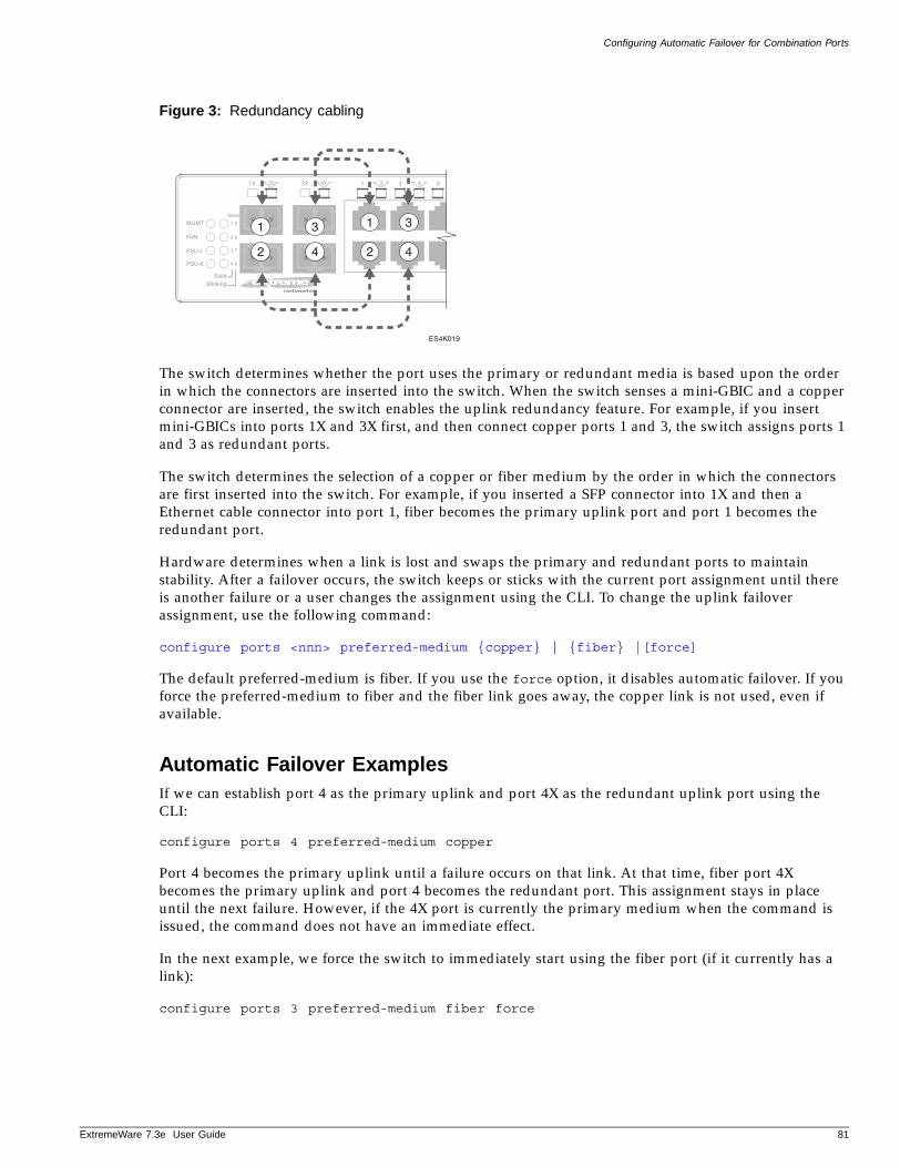
Configuring Automatic Failover for Combination Ports
ExtremeWare 7
Figure 3: Redundancy cabling
The switch determines whether the port uses the primary or redundant media is based upon the order in which the connectors are inserted into the switch. When the switch senses a mini-GBIC and a copper connector are inserted, the switch enables the uplink redundancy feature. For example, if you insert mini-GBICs into ports 1X and 3X first, and then connect copper ports 1 and 3, the switch assigns ports 1 and 3 as redundant ports.
The switch determines the selection of a copper or fiber medium by the order in which the connectors are first inserted into the switch. For example, if you inserted a SFP connector into 1X and then a Ethernet cable connector into port 1, fiber becomes the primary uplink port and port 1 becomes the redundant port.
Hardware determines when a link is lost and swaps the primary and redundant ports to maintain stability. After a failover occurs, the switch keeps or sticks with the current port assignment until there is another failure or a user changes the assignment using the CLI. To change the uplink failover assignment, use the following command:
configure ports <nnn> preferred-medium {copper} | {fiber} |[force]
The default preferred-medium is fiber. If you use the force option, it disables automatic failover. If you force the preferred-medium to fiber and the fiber link goes away, the copper link is not used, even if available.
Automatic Failover ExamplesIf we can establish port 4 as the primary uplink and port 4X as the redundant uplink port using the CLI:
configure ports 4 preferred-medium copper
Port 4 becomes the primary uplink until a failure occurs on that link. At that time, fiber port 4X becomes the primary uplink and port 4 becomes the redundant port. This assignment stays in place until the next failure. However, if the 4X port is currently the primary medium when the command is issued, the command does not have an immediate effect.
In the next example, we force the switch to immediately start using the fiber port (if it currently has a link):
configure ports 3 preferred-medium fiber force
1
2
3
4
1
2
3
4
ES4K019
.3e User Guide 81

Configuring Ports
In this example, port 3X becomes the only uplink port. If the preferred-medium was copper when the command is issued, the switch immediately switches over and begins using the fiber port. If a failure occurs on the fiber port, the switch does not use the copper port as a redundant link. To allow the redundant uplink feature to be used again, issue this command:
configure ports 3 preferred-medium fiber
82 ExtremeWare 7.3e User Guide
5 Virtual LANs (VLANs)
ExtremeWare 7
This chapter covers the following topics:
• Overview of Virtual LANs on page 83
• Types of VLANs on page 84
• VLAN Names on page 90
• Configuring VLANs on the Switch on page 91
• Displaying VLAN Settings on page 93
• MAC-Based VLANs on page 93
Setting up Virtual Local Area Networks (VLANs) on the switch eases many time-consuming tasks of network administration while increasing efficiency in network operations.
Overview of Virtual LANs
The term VLAN is used to refer to a collection of devices that communicate as if they were on the same physical LAN. Any set of ports (including all ports on the switch) is considered a VLAN. LAN segments are not restricted by the hardware that physically connects them. The segments are defined by flexible user groups you create with the command line interface.
BenefitsImplementing VLANs on your networks has the following advantages:
• VLANs help to control traffic—With traditional networks, congestion can be caused by broadcast traffic that is directed to all network devices, regardless of whether they require it. VLANs increase the efficiency of your network because each VLAN can be set up to contain only those devices that must communicate with each other.
• VLANs provide extra security—Devices within each VLAN can only communicate with member devices in the same VLAN. If a device in VLAN Marketing must communicate with devices in VLAN Sales, the traffic must cross a routing device.
• VLANs ease the change and movement of devices—With traditional networks, network administrators spend much of their time dealing with moves and changes. If users move to a different subnetwork, the addresses of each endstation must be updated manually.
.2e Installation and User Guide 83
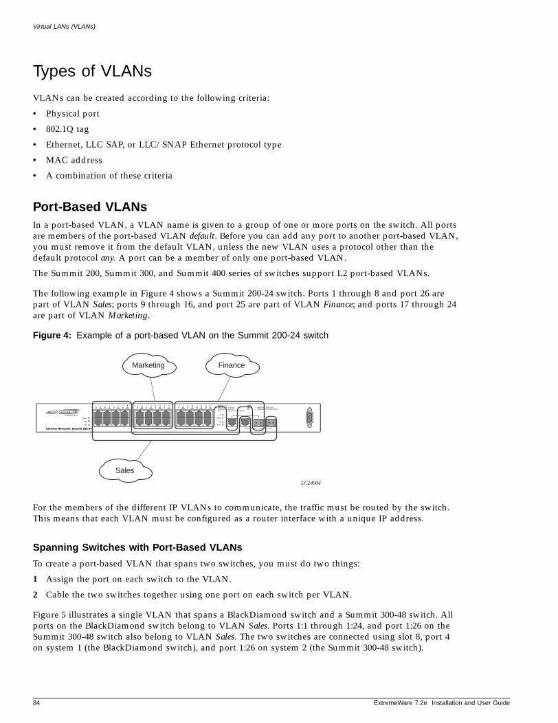
Virtual LANs (VLANs)
Types of VLANs
VLANs can be created according to the following criteria:
• Physical port
• 802.1Q tag
• Ethernet, LLC SAP, or LLC/SNAP Ethernet protocol type
• MAC address
• A combination of these criteria
Port-Based VLANsIn a port-based VLAN, a VLAN name is given to a group of one or more ports on the switch. All ports are members of the port-based VLAN default. Before you can add any port to another port-based VLAN, you must remove it from the default VLAN, unless the new VLAN uses a protocol other than the default protocol any. A port can be a member of only one port-based VLAN.
The Summit 200, Summit 300, and Summit 400 series of switches support L2 port-based VLANs.
The following example in Figure 4 shows a Summit 200-24 switch. Ports 1 through 8 and port 26 are part of VLAN Sales; ports 9 through 16, and port 25 are part of VLAN Finance; and ports 17 through 24 are part of VLAN Marketing.
Figure 4: Example of a port-based VLAN on the Summit 200-24 switch
For the members of the different IP VLANs to communicate, the traffic must be routed by the switch. This means that each VLAN must be configured as a router interface with a unique IP address.
Spanning Switches with Port-Based VLANs
To create a port-based VLAN that spans two switches, you must do two things:
1 Assign the port on each switch to the VLAN.
2 Cable the two switches together using one port on each switch per VLAN.
Figure 5 illustrates a single VLAN that spans a BlackDiamond switch and a Summit 300-48 switch. All ports on the BlackDiamond switch belong to VLAN Sales. Ports 1:1 through 1:24, and port 1:26 on the Summit 300-48 switch also belong to VLAN Sales. The two switches are connected using slot 8, port 4 on system 1 (the BlackDiamond switch), and port 1:26 on system 2 (the Summit 300-48 switch).
LC24004
Marketing Finance
Sales
84 ExtremeWare 7.2e Installation and User Guide
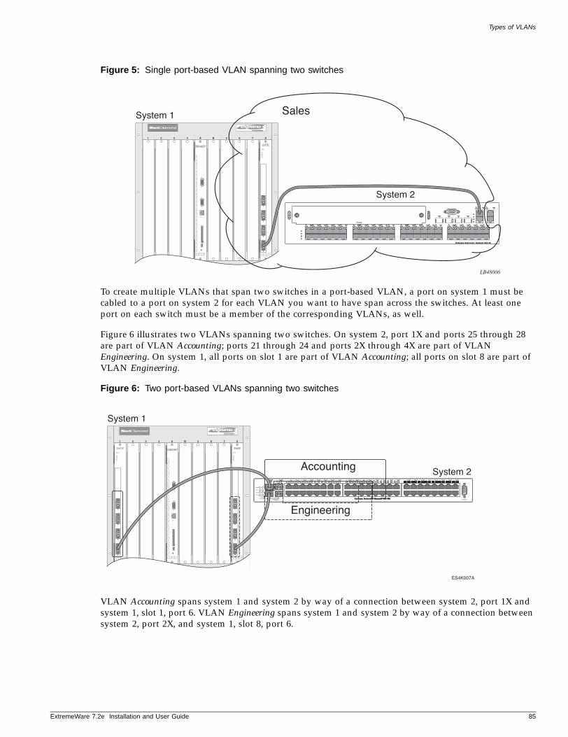
Types of VLANs
ExtremeWare 7
Figure 5: Single port-based VLAN spanning two switches
To create multiple VLANs that span two switches in a port-based VLAN, a port on system 1 must be cabled to a port on system 2 for each VLAN you want to have span across the switches. At least one port on each switch must be a member of the corresponding VLANs, as well.
Figure 6 illustrates two VLANs spanning two switches. On system 2, port 1X and ports 25 through 28 are part of VLAN Accounting; ports 21 through 24 and ports 2X through 4X are part of VLAN Engineering. On system 1, all ports on slot 1 are part of VLAN Accounting; all ports on slot 8 are part of VLAN Engineering.
Figure 6: Two port-based VLANs spanning two switches
VLAN Accounting spans system 1 and system 2 by way of a connection between system 2, port 1X and system 1, slot 1, port 6. VLAN Engineering spans system 1 and system 2 by way of a connection between system 2, port 2X, and system 1, slot 8, port 6.
LB48006
1 2 3 4 A B 5 6 7 8
4
3
2
1
System 1
System 2
Sales
ES4K007A
1 2 3 4 A B 5 6 7 8
4
3
2
1
System 1
System 2Accounting
Engineering
4
3
2
1
.2e Installation and User Guide 85
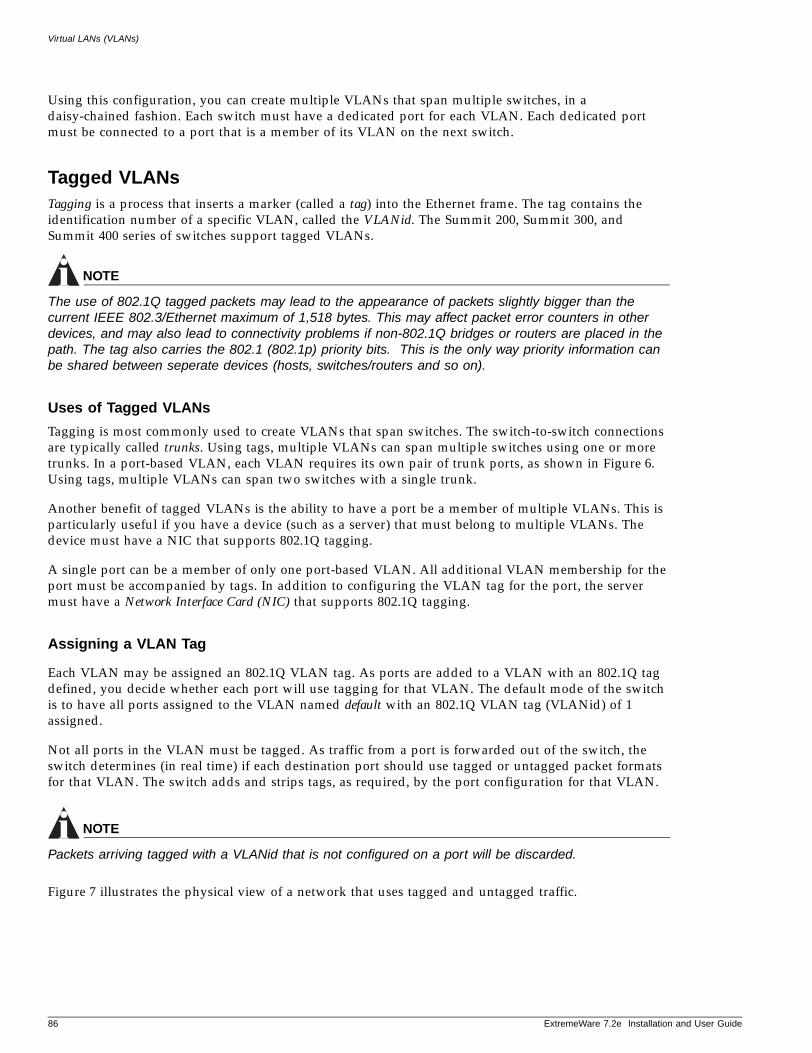
Virtual LANs (VLANs)
Using this configuration, you can create multiple VLANs that span multiple switches, in a daisy-chained fashion. Each switch must have a dedicated port for each VLAN. Each dedicated port must be connected to a port that is a member of its VLAN on the next switch.
Tagged VLANsTagging is a process that inserts a marker (called a tag) into the Ethernet frame. The tag contains the identification number of a specific VLAN, called the VLANid. The Summit 200, Summit 300, and Summit 400 series of switches support tagged VLANs.
NOTE
The use of 802.1Q tagged packets may lead to the appearance of packets slightly bigger than the current IEEE 802.3/Ethernet maximum of 1,518 bytes. This may affect packet error counters in other devices, and may also lead to connectivity problems if non-802.1Q bridges or routers are placed in the path. The tag also carries the 802.1 (802.1p) priority bits. This is the only way priority information can be shared between seperate devices (hosts, switches/routers and so on).
Uses of Tagged VLANs
Tagging is most commonly used to create VLANs that span switches. The switch-to-switch connections are typically called trunks. Using tags, multiple VLANs can span multiple switches using one or more trunks. In a port-based VLAN, each VLAN requires its own pair of trunk ports, as shown in Figure 6. Using tags, multiple VLANs can span two switches with a single trunk.
Another benefit of tagged VLANs is the ability to have a port be a member of multiple VLANs. This is particularly useful if you have a device (such as a server) that must belong to multiple VLANs. The device must have a NIC that supports 802.1Q tagging.
A single port can be a member of only one port-based VLAN. All additional VLAN membership for the port must be accompanied by tags. In addition to configuring the VLAN tag for the port, the server must have a Network Interface Card (NIC) that supports 802.1Q tagging.
Assigning a VLAN Tag
Each VLAN may be assigned an 802.1Q VLAN tag. As ports are added to a VLAN with an 802.1Q tag defined, you decide whether each port will use tagging for that VLAN. The default mode of the switch is to have all ports assigned to the VLAN named default with an 802.1Q VLAN tag (VLANid) of 1 assigned.
Not all ports in the VLAN must be tagged. As traffic from a port is forwarded out of the switch, the switch determines (in real time) if each destination port should use tagged or untagged packet formats for that VLAN. The switch adds and strips tags, as required, by the port configuration for that VLAN.
NOTE
Packets arriving tagged with a VLANid that is not configured on a port will be discarded.
Figure 7 illustrates the physical view of a network that uses tagged and untagged traffic.
86 ExtremeWare 7.2e Installation and User Guide
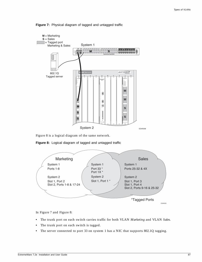
Types of VLANs
ExtremeWare 7
Figure 7: Physical diagram of tagged and untagged traffic
Figure 8 is a logical diagram of the same network.
Figure 8: Logical diagram of tagged and untagged traffic
In Figure 7 and Figure 8:
• The trunk port on each switch carries traffic for both VLAN Marketing and VLAN Sales.
• The trunk port on each switch is tagged.
• The server connected to port 33 on system 1 has a NIC that supports 802.1Q tagging.
ES4K008
1 2 3 4 A B 5 6 7 8
4
3
2
1
System 1
= Marketing= Sales
M
M
S
S
M
S
S
S= Tagged port Marketing & Sales
M
M
S
S
System 2
M SM SSS
802.1QTagged server
50015
ES4K020
*Tagged Ports
SalesSystem 1Port 33 *Port 1X *
System 2Slot 1, Port 1 *
MarketingSystem 1Ports 1-8
System 2Slot 1, Port 2Slot 2, Ports 1-8 & 17-24
System 1Ports 25-32 & 4X
System 2Slot 1, Port 3Slot 1, Port 4Slot 2, Ports 9-16 & 25-32
.2e Installation and User Guide 87
Virtual LANs (VLANs)
• The server connected to port 33 on system 1 is a member of both VLAN Marketing and VLAN Sales.
• All other stations use untagged traffic.
As data passes out of the switch, the switch determines if the destination port requires the frames to be tagged or untagged. All traffic coming from and going to the server is tagged. Traffic coming from and going to the trunk ports is tagged. The traffic that comes from and goes to the other stations on this network is not tagged.
Mixing Port-Based and Tagged VLANs
You can configure the switch using a combination of port-based and tagged VLANs. A given port can be a member of multiple VLANs, with the stipulation that only one of its VLANs uses untagged traffic. In other words, a port can simultaneously be a member of one port-based VLAN and multiple tag-based VLANs.
NOTE
For the purposes of VLAN classification, packets arriving on a port with an 802.1Q tag containing a VLANid of zero are treated as untagged.
Protocol-Based VLANs—Summit 400 onlyProtocol-based VLANs enable you to define a packet filter that the switch uses as the matching criteria to determine if a particular packet belongs to a particular VLAN.
Protocol-based VLANs are most often used in situations where network segments contain hosts running multiple protocols. For example, in Figure 9, the hosts are running both the IP and NetBIOS protocols.
The IP traffic has been divided into two IP subnets, 192.207.35.0 and 192.207.36.0. The subnets are internally routed by the switch. The subnets are assigned different VLAN names, Finance and Personnel, respectively. The remainder of the traffic belongs to the VLAN named MyCompany. All ports are members of the VLAN MyCompany.
88 ExtremeWare 7.2e Installation and User Guide
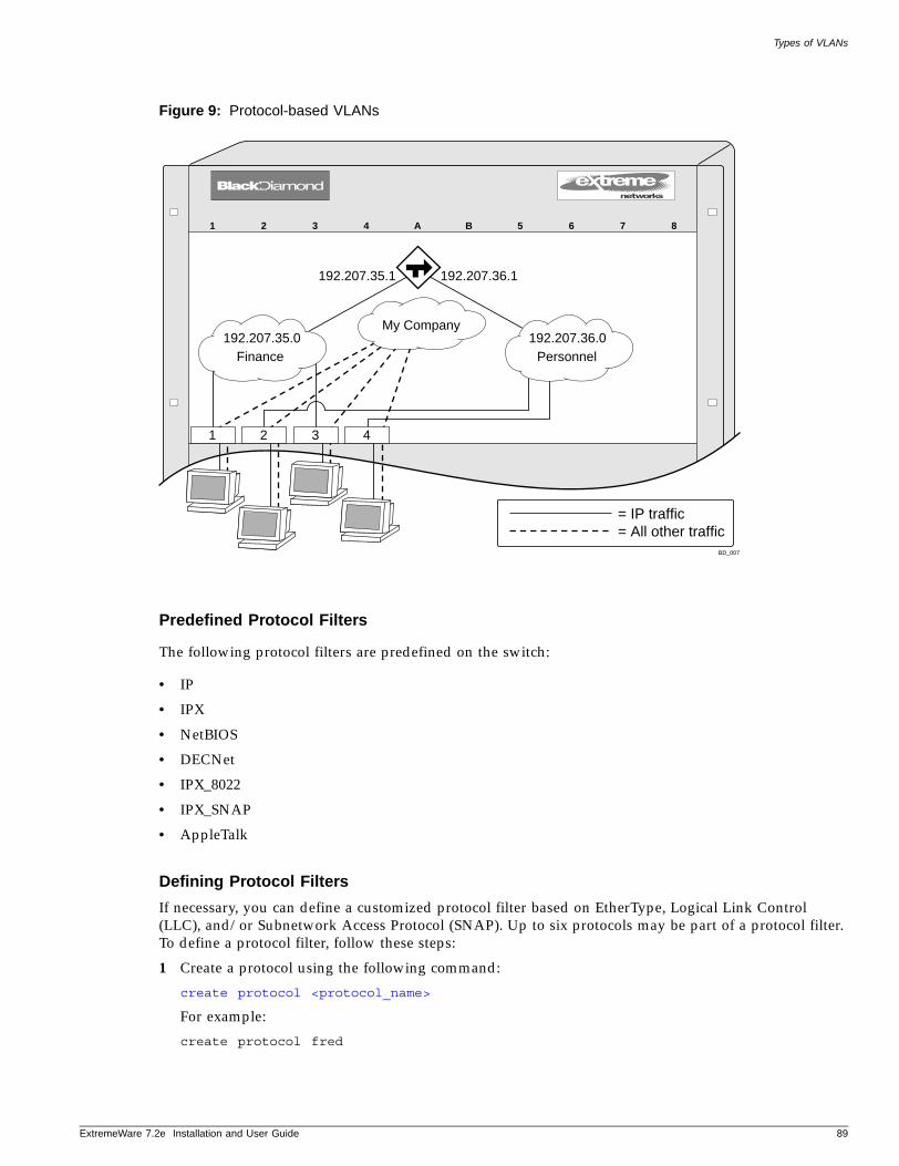
Types of VLANs
ExtremeWare 7
Figure 9: Protocol-based VLANs
Predefined Protocol Filters
The following protocol filters are predefined on the switch:
• IP
• IPX
• NetBIOS
• DECNet
• IPX_8022
• IPX_SNAP
• AppleTalk
Defining Protocol Filters
If necessary, you can define a customized protocol filter based on EtherType, Logical Link Control (LLC), and/or Subnetwork Access Protocol (SNAP). Up to six protocols may be part of a protocol filter. To define a protocol filter, follow these steps:
1 Create a protocol using the following command:
create protocol <protocol_name>
For example:
create protocol fred
1 2 3 4 A B 5 6 7 8
BD_007
1
Finance Personnel
My Company
2 3 4
= IP traffic= All other traffic
192.207.36.0192.207.35.0
192.207.36.1192.207.35.1
.2e Installation and User Guide 89
Virtual LANs (VLANs)
The protocol name can have a maximum of 32 characters.
2 Configure the protocol using the following command:
configure protocol <protocol_name> add <protocol_type> <hex_value> {<protocol_type> <hex_value>} ...
Supported protocol types include:
— etype—EtherType.
The values for etype are four-digit hexadecimal numbers taken from a list maintained by the IEEE. This list can be found at the following URL:
http://standards.ieee.org/regauth/ethertype/index.html
— llc—LLC Service Advertising Protocol (SAP).
The values for llc are four-digit hexadecimal numbers that are created by concatenating a two-digit LLC Destination SAP (DSAP) and a two-digit LLC Source SAP (SSAP).
— snap—Ethertype inside an IEEE SNAP packet encapsulation.
The values for snap are the same as the values for etype, described previously.
For example:
configure protocol fred add llc feff
configure protocol fred add snap 9999
A maximum of 15 protocol filters, each containing a maximum of six protocols, can be defined. On products that use the Inferno chip set, all 15 protocol filters can be active and configured for use. On all other platforms, no more than seven protocols can be active and configured for use.
NOTE
or more information on SNAP for Ethernet protocol types, see TR 11802-5:1997 (ISO/IEC) [ANSI/IEEE std. 802.1H, 1997 Edition].
Deleting a Protocol Filter
If a protocol filter is deleted from a VLAN, the VLAN is assigned a protocol filter of none. You can continue to configure the VLAN. However, no traffic is forwarded to the VLAN until a protocol is assigned to it.
Precedence of Tagged Packets Over Protocol FiltersIf a VLAN is configured to accept tagged packets on a particular port, incoming packets that match the tag configuration take precedence over any protocol filters associated with the VLAN.
VLAN Names
Each VLAN is given a name that can be up to 32 characters. VLAN names can use standard alphanumeric characters. The following characters are not permitted in a VLAN name:
• Space
• Comma
• Quotation mark
90 ExtremeWare 7.2e Installation and User Guide

Configuring VLANs on the Switch
ExtremeWare 7
VLAN names must begin with an alphabetical letter. Quotation marks can be used to enclose a VLAN name that includes special characters, including single quotation marks or commas. Spaces may not be included, even within quotation marks. For example, the names test, test1, and test_15 are acceptable VLAN names. The names “test&5” and “joe’s” may be used if enclosed in quotation marks. Names such as “5test” or “test 5” are not permitted.
VLAN names can be specified using the tab key for command completion.
VLAN names are locally significant. That is, VLAN names used on one switch are only meaningful to that switch. If another switch is connected to it, the VLAN names have no significance to the other switch.
NOTE
You should use VLAN names consistently across your entire network.
Default VLANThe switch ships with one default VLAN that has the following properties:
• The VLAN name is default.
• It contains all the ports on a new or initialized switch.
• The default VLAN is untagged on all ports. It has an internal VLANid of 1.
Renaming a VLANTo rename an existing VLAN, use the following command:
configure vlan <old_name> name <new_name>
The following rules apply to renaming VLANs:
• Once you change the name of the default VLAN, it cannot be changed back to default.
• You cannot create a new VLAN named default.
• You cannot change the VLAN name MacVlanDiscover. Although the switch accepts a name change, once it is rebooted, the original name is recreated.
Configuring VLANs on the Switch
This section describes the commands associated with setting up VLANs on the switch. Configuring a VLAN involves the following steps:
1 Create and name the VLAN.
2 Assign an IP address and mask (if applicable) to the VLAN, if needed.
NOTE
Each IP address and mask assigned to a VLAN must represent a unique IP subnet. You cannot configure the same IP subnet on different VLANs.
.2e Installation and User Guide 91
Virtual LANs (VLANs)
NOTE
If you plan to use this VLAN as a control VLAN for an EAPS domain, do NOT assign an IP address to the VLAN.
3 Assign a VLANid, if any ports in this VLAN will use a tag.
4 Assign one or more ports to the VLAN.
As you add each port to the VLAN, decide if the port will use an 802.1Q tag.
VLAN Configuration ExamplesThe following example creates a port-based VLAN named accounting, assigns the IP address 132.15.121.1, and assigns ports 1, 2, 3, and 6:
create vlan accountingconfigure accounting ipaddress 132.15.121.1configure default delete port 1-3,6configure accounting add port 1-3,6
NOTE
Because VLAN names are unique, you do not need to enter the keyword vlan after you have created the unique VLAN name. You can use the VLAN name alone.
The following example creates a tag-based VLAN named video on either a Summit 200 or Summit 400 series switch. It assigns the VLANid 1000. Ports 4 through 8 are added as tagged ports to the VLAN.
create vlan videoconfigure video tag 1000configure video add port 4-8 tagged
On the Summit 300-48 switch, you would code this example as:
create vlan videoconfig video tag 1000config video add port 1:4-1:8 tagged
The following example creates a VLAN named sales, with the VLANid 120 on either a Summit 200 or Summit 400 series switch. The VLAN uses both tagged and untagged ports. Ports 1 through 3 are tagged, and ports 4 and 7 are untagged. Note that when not explicitly specified, ports are added as untagged.
create vlan sales configure sales tag 120configure sales add port 1-3 taggedconfigure default delete port 4,7configure sales add port 4,7
On the Summit 300-48 switch, you would code this example as:
create vlan sales config sales tag 120config sales add port 1:1-1:3 tagged
92 ExtremeWare 7.2e Installation and User Guide

Displaying VLAN Settings
ExtremeWare 7
config sales add port 1:4,1:7
Displaying VLAN Settings
To display VLAN settings, use the following command:
show vlan {<vlan name>} <vlan name>}
The show command displays summary information about a specific VLAN, which includes:
• Name.
• VLANid.
• How the VLAN was created.
• IP address.
• STPD information.
• Protocol information.
• QoS profile information.
• Ports assigned.
• Tagged/untagged status for each port.
• How the ports were added to the VLAN.
• Number of VLANs configured on the switch.
Use the detail option to display the detailed format.
MAC-Based VLANs
MAC-based VLANs allow physical ports to be mapped to a VLAN based on the source MAC address learned in the FDB. This feature allows you to designate a set of ports that have their VLAN membership dynamically determined by the MAC address of the end station that plugs into the physical port. You can configure the source MAC address-to-VLAN mapping either offline or dynamically on the switch. For example, you could use this application for a roaming user who wants to connect to a network from a conference room. In each room, the user plugs into one of the designated ports on the switch and is mapped to the appropriate VLAN. Connectivity is maintained to the network with all of the benefits of the configured VLAN in terms of QoS, routing, and protocol support.
MAC-Based VLAN GuidelinesWhen using the MAC-to-VLAN mapping, consider the following guidelines:
• A port can only accept connections from an endstation/host and should not be connected to a layer-2 repeater device. Connecting to a layer-2 repeater device can cause certain addresses to not be mapped to their respective VLAN if they are not correctly configured in the MAC-VLAN configuration database. If a repeater device is connected to a MAC-Based VLAN port, and the configured MAC-to-VLAN mapped station enters on the repeater, any endstation that is attached to the repeater can be mapped to that VLAN while the configured endstation is active in that VLAN. Upon removal of the configured MAC-to-VLAN endstation, all other endstations lose connectivity.
.2e Installation and User Guide 93
Virtual LANs (VLANs)
• Groups are used as a security measure to allow a MAC address to enter into a VLAN only when the group mapping matches the port mapping.
As an example, the following configuration allows MAC 00:00:00:00:00:aa to enter into the VLAN only on ports 10 and 11 because of membership in group 100:
* Summit400 # show mac-vlanPort Vlan Group State10 MacVlanDiscover 100 Discover11 MacVlanDiscover 100 Discover12 MacVlanDiscover any Discover13 MacVlanDiscover any Discover14 MacVlanDiscover any DiscoverTotal Entries in Database:2 Mac Vlan Group00:00:00:00:00:aa sales 10000:00:00:00:00:01 sales any2 matching entries
• The group “any” is equivalent to the group “0”. Ports that are configured as “any” allow any MAC address to be assigned to a VLAN, regardless of group association.
• Partial configurations of the MAC to VLAN database can be downloaded to the switch using the timed download configuration feature.
MAC-Based VLAN LimitationsThe following list contains the limitations of MAC-based VLANs:
• Ports participating in MAC VLANs must first be removed from any static VLANs.
• The MAC- to-VLAN mapping can only be associated with VLANs that exist on the switch.
• A MAC address cannot be configured to associate with more than 1 VLAN. If this is attempted, the MAC address is associated with the most recent VLAN entry in the MAC-to-VLAN database.
• The feature is intended to support one client per physical port. Once a client MAC address has successfully registered, the VLAN association remains until the port connection is dropped or the FDB entry ages out.
• The MAC-to-VLAN database is stored in memory, only. It is not stored in NVRAM. As a result, the the VLAN associations are lost during a reboot and you must perform an incremental download of the MAC-to-VLAN database to recover the VLAN associations.
MAC-Based VLAN Example In this following example, three VLANs are created: engineering, marketing, and sales. A single MAC address is associated with each VLAN. The MAC address 00:00:00:00:00:02 has a group number of “any” or “0” associated with it, allowing it to be plugged into any port that is in MacVlanDiscover mode (ports 10-15 in this case). The MAC address 00:00:00:00:00:01 has a group number of 10 associated with it, and can only be assigned to a VLAN if inserted into ports 16 or 17. The MAC address 00:00:00:00:00:03 has a group number of 200 associated with it and can only be inserted into ports 18 through 20.
enable mac-vlan mac-group any ports 10-15enable mac-vlan mac-group 10 ports 16-17enable mac-vlan mac-group 200 ports 18-20configure mac-vlan add mac-address 00:00:00:00:00:01 mac-group 10 engineering
94 ExtremeWare 7.2e Installation and User Guide
MAC-Based VLANs
ExtremeWare 7
configure mac-vlan add mac-address 00:00:00:00:00:02 mac-group any marketingconfigure mac-vlan add mac-address 00:00:00:00:00:03 mac-group 200 sales
Timed Configuration Download for MAC-Based VLANsTo allow centralized control of MAC-based VLANs over multiple switches, a timed TFTP configuration download allows you to download incremental configuration files from a primary or secondary server at specified time intervals. The timed downloads are configurable in 24 hour intervals. When a switch reboots, the configuration is automatically downloaded immediately after booting, per the configured primary and secondary servers.
To configure the primary and/or secondary server and file name, use the following command:
configure download server [primary | secondary] [<ip address> | <hostname>] <filename>
To enable timed interval downloads, use the following command:
download configuration every <time>
To display timed download information, use the following command:
show switch
Example
In relation to MAC-based VLANs, the downloaded file is an ASCII file that consists of CLI commands used to configure the most recent MAC-to-VLAN database. This feature is different from the normal download configuration command in that it allows incremental configuration without the automatic rebooting of the switch.
The following example shows an incremental configuration file for MAC-based VLAN information that updates the database and saves changes:
configure mac-vlan add mac-address 00:00:00:00:00:01 mac-group any engineeringconfigure mac-vlan add mac-address 00:00:00:00:ab:02 mac-group any engineeringconfigure mac-vlan add mac-address 00:00:00:00:cd:04 mac-group any sales..configure mac-vlan add mac-address 00:00:00:00:ab:50 mac-group any salesconfigure mac-vlan add mac-address 00:00:00:00:cd:60 mac-group any salessave
.2e Installation and User Guide 95

Virtual LANs (VLANs)
96 ExtremeWare 7.2e Installation and User Guide
6 Forwarding Database (FDB)
ExtremeWare 7
This chapter describes the following topics:
• Overview of the FDB on page 97
• Associating QoS Profiles with an FDB Entry on page 99
• FDB Configuration Examples on page 100
• Displaying FDB Entries on page 101
Overview of the FDB
The switch maintains a database of all media access control (MAC) addresses received on all of its ports. It uses the information in this database to decide whether a frame should be forwarded or filtered.
FDB ContentsEach FDB entry consists of:
• The MAC address of the device
• An identifier for the port and VLAN on which it was received
• The age of the entry
• The number of IP FDB entries that use this MAC address as a next hop or last hop
• Flags
Frames destined for MAC addresses that are not in the FDB are flooded to all members of the VLAN.
How FDB Entries Get AddedEntries are added into the FDB in the following ways:
• The switch can learn entries by examining packets it receives. The system updates its FDB with the source MAC address from a packet, the VLAN, and the port identifier on which the source packet is received.
The ability to learn MAC addresses can be enabled or disabled on a port-by-port basis. You can also limit the number of addresses that can be learned, or you can “lock down” the current entries and prevent additional MAC address learning.
.3e User Guide 97
Forwarding Database (FDB)
• You can enter and update entries using the command line interface (CLI).
• Certain static entries are added by the system upon switch boot up.
FDB Entry TypesFDB entries may be dynamic or static, and may be permanent or non-permanent. The Summit “e” series of switches support at least 8,191 layer 2 FDB entries and 2,047 layer 3 FDB entries.
The following describes the types of entries that can exist in the FDB:
• Dynamic entries—A dynamic entry is learned by the switch by examining packets to determine the source MAC address, VLAN, and port information. The switch then creates or updates an FDB entry for that MAC address. Initially, all entries in the database are dynamic, except for certain entries created by the switch at boot up.
Entries in the database are removed (aged-out) if, after a period of time (aging time), if the device has not transmitted. This prevents the database from becoming full with obsolete entries by ensuring that when a device is removed from the network, its entry is deleted from the database. Dynamic entries are deleted from the database if the switch is reset or a power off/on cycle occurs. Dynamic entries are flushed and relearned (updated) when any of the following take place:
— A VLAN is deleted.
— A VLAN identifier (VLANid) is changed.
— A port mode is changed (tagged/untagged).
— A port is deleted from a VLAN.
— A port is disabled.
— A port enters blocking state.
— A port QoS setting is changed.
— A port goes down (link down).
A non-permanent dynamic entry is initially created when the switch identifies a new source MAC address that does not yet have an entry in the FDB. The entry may then be updated as the switch continues to encounter the address in the packets it examines. These entries are identified by the “d” flag in show fdb output.
A permanent dynamic entry is created by command through the CLI, but may then be updated as the switch encounters the MAC address in the packets that it examines. A permanent dynamic entry is typically used to associate QoS profiles with the FDB entry. Permanent dynamic entries are identified by the “p” and “d” flags in the show fdb output.
Both types of dynamic entries age—a dynamic entry will be removed from the FDB (aged-out) if the device does not transmit for a specified period of time (the aging time). This prevents the database from becoming full with obsolete entries by ensuring that when a device is removed from the network, its entry is deleted from the database. The aging time is configurable. For more information about setting the aging time, see “Configuring the FDB Aging Time” on page 101 later in this chapter.
• Static entries—A static entry does not age, and does not get updated through the learning process. It is maintained exactly as it was created. Conditions that cause dynamic entries to be updated, such as VLAN or port configuration changes, do not affect static entries.
If the same MAC address is detected on another virtual port that is not defined in the static FDB entry for the MAC address, it is handled as a blackhole entry.
98 ExtremeWare 7.3e User Guide
Associating QoS Profiles with an FDB Entry
ExtremeWare 7
A permanent static entry is created through the command line interface, and can be used to associate QoS profiles with a non-aging FDB entry. Permanent static entries are identified by the “s” and “p” flags in show fdb output.
A locked static entry is an entry that was originally learned dynamically, but has been made static (locked) using the MAC address lock-down feature. It is identified by the “s” and “l” flags in show fdb output. See “Network Login” on page 150 for more information about MAC address lock-down.
Non-permanent static entries are created by the switch software for various reasons, typically upon switch boot up. They are identified by the “s” flag in show fdb output.
If the FDB entry aging time is set to zero, all entries in the database are considered static, non-aging entries. This means that they do not age, but they are still deleted if the switch is reset.
• Permanent entries—Permanent entries are retained in the database if the switch is reset or a power off/on cycle occurs. Permanent entries must be created by the system administrator through the command line interface. A permanent entry can either be a unicast or multicast MAC address.
Permanent entries may be static, meaning they do not age or get updated, or they may be dynamic, meaning that they do age and can be updated via learning.
Permanent entries can have QoS profiles associated with the MAC address. A different QoS profiles may be associated with the MAC address when it is a destination address (an egress QoS profile) than when it is a source address (ingress QoS profile). Once created, permanent entries stay the same as when they were created.
All entries entered by way of the command-line interface are stored as permanent.
The Summit 300-48 can support a maximum of 128 permanent entries.
The Summit 200, Summit 300-24 and the Summit 400-48t can support a maximum of 64 permanent entries.
• Blackhole entries—A blackhole entry configures the switch to discard packets with a specified MAC destination address. Blackhole entries are useful as a security measure or in special circumstances where a specific source or destination address must be discarded. Blackhole entries may be created through the CLI, or they may be created by the switch when a port’s learning limit has been exceeded.
Blackhole entries are treated like permanent entries in the event of a switch reset or power off/on cycle. Blackhole entries are never aged out of the database.
Disabling MAC Address LearningBy default, MAC address learning is enabled on all ports. You can disable learning on specified ports using the following command:
disable learning ports <portlist>
If MAC address learning is disabled, only broadcast traffic, EDP traffic, and packets destined to a permanent MAC address matching that port number, are forwarded. Use this command in a secure environment where access is granted via permanent forwarding databases (FDBs) per port.
Associating QoS Profiles with an FDB Entry
You can associate QoS profiles with a MAC address (and VLAN) of a device by creating a permanent FDB entry and specifying QoS profiles for ingress or egress, or both. The permanent FDB entry can be either dynamic (it is learned and can be aged out) or static.
.3e User Guide 99
Forwarding Database (FDB)
To associate a QoS profile with a dynamic FDB entry, use the following command:
create fdbentry [<mac_address> | any-mac] vlan <vlan name> dynamic [ingress-qosprofile <qosprofile>{ingress-qosprofile <inqosprofile>}]
This command associates QoS profiles with packets received from or destined for the specified MAC address, while still allowing the FDB entry to be dynamically learned. If you specify only the ingress QoS profile, the egress QoS profile defaults to none, and vice-versa. If both profiles are specified, the source MAC address of an ingress packet and the destination MAC address of an egress packet are examined for QoS profile assignment.
The FDB entry is not actually created until the MAC address is encountered as the source MAC address in a packet. Thus, initially the entry may not appear in the show fdb output. Once the entry has been learned, it is created as a permanent dynamic entry, designated by “dpm” in the flags field of the show fdb output.
You can display permanent FDB entries, including their QoS profile associations by using the permanent option in the following command:
show fdb {<mac_address> | permanent | ports <portlist> | vlan <vlan name>}
To associate a QoS profile with a permanent FDB entry, use the following command:
create fdbentry <mac_address> vlan <vlan name> ports [<portlist> | all] {qosprofile <qosprofile>}{ingress-qosprofile <inqosprofile>}
This entry will not be aged out, and no learning will occur. If the same MAC address is encountered through a virtual port not specified in the portlist, it will be handled as a blackhole entry.
Using the any-mac keyword, you can enable traffic from a QoS VLAN to have higher priority than 802.1p traffic. Normally, an 802.1p packet has a higher priority over the VLAN classification. In order to use this feature, you must create a wildcard permanent FDB entry named any-mac and apply the QoS profile to the individual MAC entry.
NOTE
For more information on QoS profiles, see Chapter 7.
FDB Configuration Examples
The following example adds a permanent static entry to the FDB on a Summit 300-48:
create fdbentry 00:E0:2B:12:34:56 vlan marketing port 1:4
The permanent entry has the following characteristics:
• MAC address is 00:E0:2B:12:34:56.
• VLAN name is marketing.
• Port number for this device is 1:4.
If the MAC address 00:E0:2B:12:34:56 is encountered on any port/VLAN other than VLAN marketing, port 1:4, it will be handled as a blackhole entry, and packets from that source will be dropped.
100 ExtremeWare 7.3e User Guide
Displaying FDB Entries
ExtremeWare 7
This example associates the QoS profile qp2 with a dynamic entry for the device at MAC address 00:A0:23:12:34:56 on VLAN net34 that will be learned by the FDB:
create fdbentry 00:A0:23:12:34:56 vlan net34 dynamic qosprofile qp2
This entry has the following characteristics:
• MAC address is 00:A0:23:12:34:56.
• VLAN name is net34.
• The entry will be learned dynamically.
• QoS profile qp2 will be applied as an egress QoS profile when the entry is learned.
Overriding 802.1p Priority
This example associates the QoS profile qp5 with the wildcard permanent FDB entry any-mac on VLAN v110:
create fdbentry any-mac vlan v110 dynamic ingress-qosprofile qp5
Configuring the FDB Aging Time
You can configure the again time for dynamic FDB entries using the following command:
configure fdb agingtime <seconds>
If the aging time is set to zero, all aging entries in the database are defined as static, nonaging entries. This means they will not age out, but non-permanent static entries can be deleted if the switch is reset.
Displaying FDB Entries
To display FDB entries, use the following command:
show fdb {<mac_address> | permanent | ports <portlist> | vlan <vlan name>}
where the following is true:
• mac_address—Displays the entry for a particular MAC address.
• broadcast-mac—Specifies the broadcast MAC address. May be used as an alternate to the colon-separated byte form of the address ff:ff:ff:ff:ff:ff
• permanent—Displays all permanent entries, including the ingress and egress QoS profiles.
• ports <portlist>—Displays the entries for a set of ports or slots and ports.
• vlan <vlan name>—Displays the entries for a VLAN.
With no options, the command displays all FDB entries.
See the ExtremeWare 7.3e Command Reference Guide for details of the commands related to the FDB.
.3e User Guide 101

Forwarding Database (FDB)
102 ExtremeWare 7.3e User Guide
7 Quality of Service (QoS)
ExtremeWare 7
This chapter covers the following topics:
• Overview of Policy-Based Quality of Service on page 104
• Applications and Types of QoS on page 104
• Configuring QoS on page 106
• QoS Profiles on page 106
• Traffic Groupings on page 107
— IP-Based Traffic Groupings on page 108
— MAC-Based Traffic Groupings on page 108
— Explicit Class of Service (802.1p and DiffServ) Traffic Groupings on page 109
— Configuring DiffServ on page 111
— Verifying Configuration and Performance on page 113
• Verifying Configuration and Performance on page 113
• Verifying Configuration and Performance on page 113
• Modifying a QoS Configuration on page 115
• on page 115
• on page 115
Policy-based Quality of Service (QoS) is a feature of ExtremeWare and the Extreme switch architecture that allows you to specify different service levels for traffic traversing the switch. Policy-based QoS is an effective control mechanism for networks that have heterogeneous traffic patterns. Using Policy-based QoS, you can specify the service level that a particular traffic type receives.
.3e User Guide 103
Quality of Service (QoS)
Overview of Policy-Based Quality of Service
Policy-based QoS allows you to protect bandwidth for important categories of applications or specifically limit the bandwidth associated with less critical traffic. For example, if voice–over-IP traffic requires a reserved amount of bandwidth to function properly, using policy-based QoS, you can reserve sufficient bandwidth critical to this type of application. Other applications deemed less critical can be limited so as to not consume excessive bandwidth. The switch contains separate hardware queues on every physical port. The prioritization parameters that modify the forwarding behavior of the switch affect how the switch transmits traffic for a given hardware queue on a physical port. Up to eight physical queues per port are available on the Summit 400 and four queues on the Summit 200 and Summit 300 switches. On all series “e” switches, QoS is enforced at the ingress port.
NOTE
Policy-based QoS has no impact on switch performance. Using even the most complex traffic groupings has no cost in terms of switch performance.
Applications and Types of QoS
Different applications have different QoS requirements. The following applications are ones that you will most commonly encounter and need to prioritize:
• Voice applications
• Video applications
• Critical database applications
• Web browsing applications
• File server applications
General guidelines for each traffic type are given below and summarized in Table 12. Consider them as general guidelines and not strict recommendations. Once QoS parameters are set, you can monitor the performance of the application to determine if the actual behavior of the applications matches your expectations. It is very important to understand the needs and behavior of the particular applications you wish to protect or limit. Behavioral aspects to consider include bandwidth needs, sensitivity to latency and jitter, and sensitivity and impact of packet loss.
Voice ApplicationsVoice applications typically demand small amounts of bandwidth. However, the bandwidth must be constant and predictable because voice applications are typically sensitive to latency (inter-packet delay) and jitter (variation in inter-packet delay). The most important QoS parameter to establish for voice applications is minimum bandwidth, followed by priority.
Video ApplicationsVideo applications are similar in needs to voice applications, with the exception that bandwidth requirements are somewhat larger, depending on the encoding. It is important to understand the behavior of the video application being used. For example, in the playback of stored video streams, some applications can transmit large amounts of data for multiple streams in one “spike,” with the expectation that the end-stations will buffer significant amounts of video-stream data. This can present a
104 ExtremeWare 7.3e User Guide
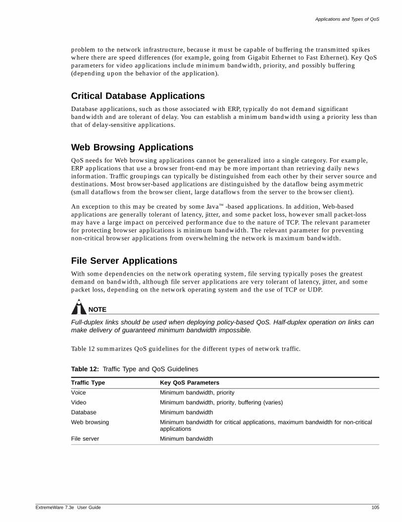
Applications and Types of QoS
ExtremeWare 7
problem to the network infrastructure, because it must be capable of buffering the transmitted spikes where there are speed differences (for example, going from Gigabit Ethernet to Fast Ethernet). Key QoS parameters for video applications include minimum bandwidth, priority, and possibly buffering (depending upon the behavior of the application).
Critical Database ApplicationsDatabase applications, such as those associated with ERP, typically do not demand significant bandwidth and are tolerant of delay. You can establish a minimum bandwidth using a priority less than that of delay-sensitive applications.
Web Browsing ApplicationsQoS needs for Web browsing applications cannot be generalized into a single category. For example, ERP applications that use a browser front-end may be more important than retrieving daily news information. Traffic groupings can typically be distinguished from each other by their server source and destinations. Most browser-based applications are distinguished by the dataflow being asymmetric (small dataflows from the browser client, large dataflows from the server to the browser client).
An exception to this may be created by some Java™ -based applications. In addition, Web-based applications are generally tolerant of latency, jitter, and some packet loss, however small packet-loss may have a large impact on perceived performance due to the nature of TCP. The relevant parameter for protecting browser applications is minimum bandwidth. The relevant parameter for preventing non-critical browser applications from overwhelming the network is maximum bandwidth.
File Server ApplicationsWith some dependencies on the network operating system, file serving typically poses the greatest demand on bandwidth, although file server applications are very tolerant of latency, jitter, and some packet loss, depending on the network operating system and the use of TCP or UDP.
NOTE
Full-duplex links should be used when deploying policy-based QoS. Half-duplex operation on links can make delivery of guaranteed minimum bandwidth impossible.
Table 12 summarizes QoS guidelines for the different types of network traffic.
Table 12: Traffic Type and QoS Guidelines
Traffic Type Key QoS Parameters
Voice Minimum bandwidth, priority
Video Minimum bandwidth, priority, buffering (varies)
Database Minimum bandwidth
Web browsing Minimum bandwidth for critical applications, maximum bandwidth for non-critical applications
File server Minimum bandwidth
.3e User Guide 105
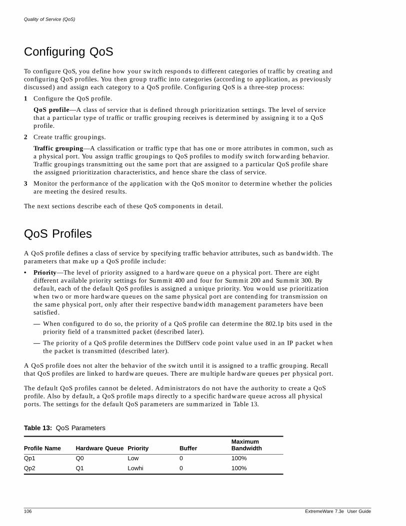
Quality of Service (QoS)
Configuring QoS
To configure QoS, you define how your switch responds to different categories of traffic by creating and configuring QoS profiles. You then group traffic into categories (according to application, as previously discussed) and assign each category to a QoS profile. Configuring QoS is a three-step process:
1 Configure the QoS profile.
QoS profile—A class of service that is defined through prioritization settings. The level of service that a particular type of traffic or traffic grouping receives is determined by assigning it to a QoS profile.
2 Create traffic groupings.
Traffic grouping—A classification or traffic type that has one or more attributes in common, such as a physical port. You assign traffic groupings to QoS profiles to modify switch forwarding behavior. Traffic groupings transmitting out the same port that are assigned to a particular QoS profile share the assigned prioritization characteristics, and hence share the class of service.
3 Monitor the performance of the application with the QoS monitor to determine whether the policies are meeting the desired results.
The next sections describe each of these QoS components in detail.
QoS Profiles
A QoS profile defines a class of service by specifying traffic behavior attributes, such as bandwidth. The parameters that make up a QoS profile include:
• Priority—The level of priority assigned to a hardware queue on a physical port. There are eight different available priority settings for Summit 400 and four for Summit 200 and Summit 300. By default, each of the default QoS profiles is assigned a unique priority. You would use prioritization when two or more hardware queues on the same physical port are contending for transmission on the same physical port, only after their respective bandwidth management parameters have been satisfied.
— When configured to do so, the priority of a QoS profile can determine the 802.1p bits used in the priority field of a transmitted packet (described later).
— The priority of a QoS profile determines the DiffServ code point value used in an IP packet when the packet is transmitted (described later).
A QoS profile does not alter the behavior of the switch until it is assigned to a traffic grouping. Recall that QoS profiles are linked to hardware queues. There are multiple hardware queues per physical port.
The default QoS profiles cannot be deleted. Administrators do not have the authority to create a QoS profile. Also by default, a QoS profile maps directly to a specific hardware queue across all physical ports. The settings for the default QoS parameters are summarized in Table 13.
Table 13: QoS Parameters
Profile Name Hardware Queue Priority BufferMaximum Bandwidth
Qp1 Q0 Low 0 100%
Qp2 Q1 Lowhi 0 100%
106 ExtremeWare 7.3e User Guide
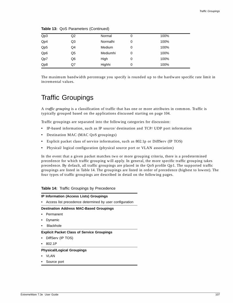
Traffic Groupings
ExtremeWare 7
The maximum bandwidth percentage you specify is rounded up to the hardware specific rate limit in incremental values.
Traffic Groupings
A traffic grouping is a classification of traffic that has one or more attributes in common. Traffic is typically grouped based on the applications discussed starting on page 104.
Traffic groupings are separated into the following categories for discussion:
• IP-based information, such as IP source/destination and TCP/UDP port information
• Destination MAC (MAC QoS groupings)
• Explicit packet class of service information, such as 802.1p or DiffServ (IP TOS)
• Physical/logical configuration (physical source port or VLAN association)
In the event that a given packet matches two or more grouping criteria, there is a predetermined precedence for which traffic grouping will apply. In general, the more specific traffic grouping takes precedence. By default, all traffic groupings are placed in the QoS profile Qp1. The supported traffic groupings are listed in Table 14. The groupings are listed in order of precedence (highest to lowest). The four types of traffic groupings are described in detail on the following pages.
Qp3 Q2 Normal 0 100%
Qp4 Q3 Normalhi 0 100%
Qp5 Q4 Medium 0 100%
Qp6 Q5 Mediumhi 0 100%
Qp7 Q6 High 0 100%
Qp8 Q7 Highhi 0 100%
Table 14: Traffic Groupings by Precedence
IP Information (Access Lists) Groupings
• Access list precedence determined by user configuration
Destination Address MAC-Based Groupings
• Permanent
• Dynamic
• Blackhole
Explicit Packet Class of Service Groupings
• DiffServ (IP TOS)
• 802.1P
Physical/Logical Groupings
• VLAN
• Source port
Table 13: QoS Parameters (Continued)
.3e User Guide 107
Quality of Service (QoS)
IP-Based Traffic GroupingsIP-based traffic groupings are based on any combination of the following items:
• IP source or destination address
• TCP or UDP protocols
• TCP/UDP port information
IP-based traffic groupings are defined using access lists. Access lists are discussed in detail in “IP Access Lists (ACLs)” on page 142. By supplying a named QoS profile at the end of the access list command syntax, you can prescribe the bandwidth management and priority handling for that traffic grouping. This level of packet filtering has no impact on performance.
For example, to create an IP-based traffic grouping, use the following commands:
create access-mask amask source-ip / 24 dest-ip / 24 precedence 2000
create access-list alist "amask" dest-ip 10.1.2.1/24 source-ip 10.1.1.1/24 permitqosprofile qp3
To create a MAC-based traffic grouping, use this command:
create fdbentry 00 : 11 : 22 : 33 : 44 : 55 vlan "Default" dynamic qosprofile "QP3"
MAC-Based Traffic GroupingsQoS profiles can be assigned to destination MAC addresses. MAC-based traffic groupings are configured using the create fdb... command:
The MAC address options, defined below, are as follows:
• Permanent
• Dynamic
• Blackhole
NOTE
On the Summit 400 broadcast MAC entries may not be associated with a QoS.
Permanent MAC addresses
Permanent MAC addresses can be assigned a QoS profile whenever traffic is destined to the MAC address. This can be done when you create a permanent FDB entry using the following command:
create fdbentry <mac_address> vlan <vlan name> ports [<portlist> | all] {qosprofile <qosprofile>}{ingress-qosprofile <inqosprofile>}
For example:
create fdbentry 00:11:22:33:44:55 vlan default port 4:1 qosprofile qp2
108 ExtremeWare 7.3e User Guide
Traffic Groupings
ExtremeWare 7
Dynamic MAC Addresses
Dynamic MAC addresses can be assigned a QoS profile whenever traffic is coming from or going to the MAC address. This is done using the following command:
create fdbentry [<mac_address> | any-mac] vlan <vlan name> dynamic [ingress-qosprofile <qosprofile>{ingress-qosprofile <inqosprofile>}]
For any port on which the specified MAC address is learned in the specified VLAN, the port is assigned the specified QoS profile. For example:
create fdbentry 00 : 11 : 22 : 33 : 44 : 55 vlan "Default" dynamic ingress-qosprofile "QP1" qosprofile qp2
The QoS profile is assigned when the MAC address is learned. If a client's location moves, the assigned QoS profile moves with the device. If the MAC address entry already exists in the FDB, you can clear the forwarding database so that the QoS profile can be applied when the entry is added again. Use the following command to clear the FDB:
clear fdb {<mac_address> | blackhole | ports <portlist> | vlan <vlan name>}
Blackhole MAC Address
Using the blackhole option configures the switch to not forward any packets to the destination MAC address on any ports for the VLAN specified. The blackhole option is configured using the following command:
create fdbentry <mac_address> vlan <vlan name> blackhole {source-mac | dest-mac | both}
For example:
create fdbentry 00:11:22:33:44:55 vlan default blackhole
Verifying MAC-Based QoS Settings
To verify any of the MAC-based QoS settings, use either the command
show fdb permanent
or the command
show qosprofile {<qosprofile>} {port <portlist>}
Explicit Class of Service (802.1p and DiffServ) Traffic GroupingsThis category of traffic groupings describes what is sometimes referred to as explicit packet marking, and refers to information contained within a packet intended to explicitly determine a class of service. That information includes:
• IP DiffServ code points, formerly known as IP TOS bits
• Prioritization bits used in IEEE 802.1p packets
An advantage of explicit packet marking is that the class of service information can be carried throughout the network infrastructure, without repeating what can be complex traffic grouping policies at each switch location. Another advantage is that end stations can perform their own packet marking
.3e User Guide 109
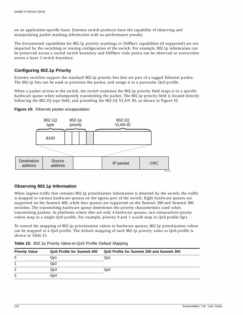
Quality of Service (QoS)
on an application-specific basis. Extreme switch products have the capability of observing and manipulating packet marking information with no performance penalty.
The documented capabilities for 802.1p priority markings or DiffServ capabilities (if supported) are not impacted by the switching or routing configuration of the switch. For example, 802.1p information can be preserved across a routed switch boundary and DiffServ code points can be observed or overwritten across a layer 2 switch boundary.
Configuring 802.1p Priority
Extreme switches support the standard 802.1p priority bits that are part of a tagged Ethernet packet. The 802.1p bits can be used to prioritize the packet, and assign it to a particular QoS profile.
When a packet arrives at the switch, the switch examines the 802.1p priority field maps it to a specific hardware queue when subsequently transmitting the packet. The 802.1p priority field is located directly following the 802.1Q type field, and preceding the 802.1Q VLAN ID, as shown in Figure 10.
Figure 10: Ethernet packet encapsulation
Observing 802.1p Information
When ingress traffic that contains 802.1p prioritization information is detected by the switch, the traffic is mapped to various hardware queues on the egress port of the switch. Eight hardware queues are supported on the Summit 400, while four queues are supported on the Summit 200 and Summit 300 switches. The transmitting hardware queue determines the priority characteristics used when transmitting packets. In platforms where ther are only 4 hardware queues, two consecutives piority values map to a single QoS profile. For example, priority 0 and 1 would map to QoS profile Qp1.
To control the mapping of 802.1p prioritization values to hardware queues, 802.1p prioritization values can be mapped to a QoS profile. The default mapping of each 802.1p priority value to QoS profile is shown in Table 15.
Table 15: 802.1p Priority Value-to-QoS Profile Default Mapping
Priority Value QoS Profile for Summit 400 QoS Profile for Summit 200 and Summit 300
0 Qp1 Qp1
1 Qp2
2 Qp3 Qp2
3 Qp4
EW_024
Sourceaddress
802.1Qtype
802.1ppriority
802.1QVLAN ID
IP packet CRCDestinationaddress
8100
110 ExtremeWare 7.3e User Guide
Traffic Groupings
ExtremeWare 7
Configuring 802.1p Priority For Slow Path Traffic
Some traffic can originate on the switch, for example Ping or Telnet packets. This traffic comes from the switch CPU and is referred to as slow path traffic. This traffic is internally tagged with an 802.1p priority of 7, by default, and egresses the VLAN through the highest queue. If you want to set a different tag (and priority) use the following command to set the priority to a number between 0 and 7:
configure vlan <vlan name> priority <priority>
Other traffic transported across the switch and VLAN will not be changed, in other words, the 802.1p values will not be affected by the VLAN priority setting.
Replacing 802.1p Priority Information
By default, 802.1p priority information is not replaced or manipulated, and the information observed on ingress is preserved when transmitting the packet. This behavior is not affected by the switching or routing configuration of the switch.
However, the switch is capable of replacing the 802.1p priority information. To replace 802.1p priority information, you will use an access list to set the 802.1p value. See “IP Access Lists (ACLs)” on page 142, for more information on using access lists. You will use the set dot1p <dot1p_value> parameter of the create access-list command to replace the value. The packet is then placed on the queue that corresponds to the new 802.1p value.
Configuring DiffServContained in the header of every IP packet is a field for IP Type of Service (TOS), now also called the DiffServ field. The TOS field is used by the switch to determine the type of service provided to the packet.
Observing DiffServ code points as a traffic grouping mechanism for defining QoS policies and overwriting the Diffserv code point fields are supported.
Figure 11 shows the encapsulation of an IP packet header.
4 Qp5 Qp3
5 Qp6
6 Qp7 Qp4
7 Qp8
Table 15: 802.1p Priority Value-to-QoS Profile Default Mapping (Continued)
Priority Value QoS Profile for Summit 400 QoS Profile for Summit 200 and Summit 300
.3e User Guide 111
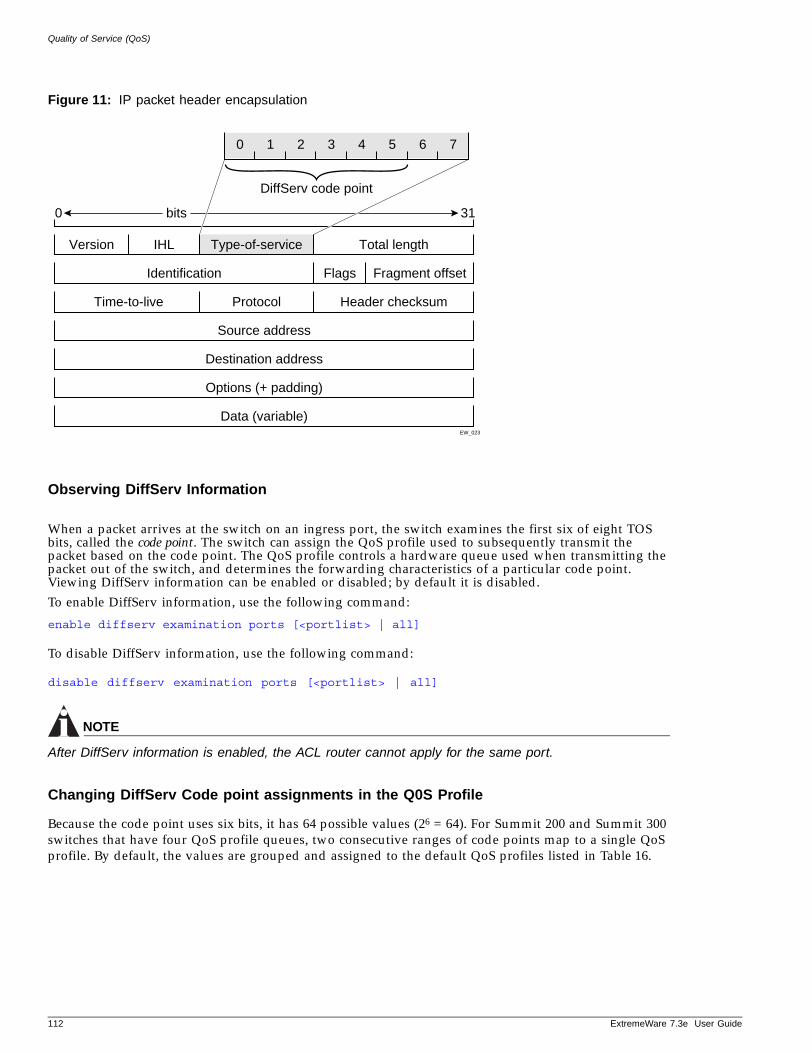
Quality of Service (QoS)
Figure 11: IP packet header encapsulation
Observing DiffServ Information
When a packet arrives at the switch on an ingress port, the switch examines the first six of eight TOS bits, called the code point. The switch can assign the QoS profile used to subsequently transmit the packet based on the code point. The QoS profile controls a hardware queue used when transmitting the packet out of the switch, and determines the forwarding characteristics of a particular code point. Viewing DiffServ information can be enabled or disabled; by default it is disabled.To enable DiffServ information, use the following command:
enable diffserv examination ports [<portlist> | all]
To disable DiffServ information, use the following command:
disable diffserv examination ports [<portlist> | all]
NOTE
After DiffServ information is enabled, the ACL router cannot apply for the same port.
Changing DiffServ Code point assignments in the Q0S Profile
Because the code point uses six bits, it has 64 possible values (26 = 64). For Summit 200 and Summit 300 switches that have four QoS profile queues, two consecutive ranges of code points map to a single QoS profile. By default, the values are grouped and assigned to the default QoS profiles listed in Table 16.
EW_023
Type-of-service
DiffServ code point
IHL
Data (variable)
0 bits 31
Options (+ padding)
Destination address
Source address
0 7654321
Total lengthVersion
ProtocolTime-to-live Header checksum
FlagsIdentification Fragment offset
112 ExtremeWare 7.3e User Guide
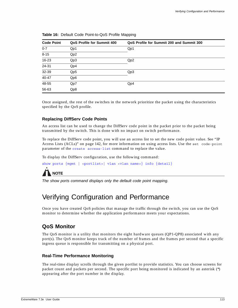
Verifying Configuration and Performance
ExtremeWare 7
Once assigned, the rest of the switches in the network prioritize the packet using the characteristics specified by the QoS profile.
Replacing DiffServ Code Points
An access list can be used to change the DiffServ code point in the packet prior to the packet being transmitted by the switch. This is done with no impact on switch performance.
To replace the DiffServ code point, you will use an access list to set the new code point value. See “IP Access Lists (ACLs)” on page 142, for more information on using access lists. Use the set code-point parameter of the create access-list command to replace the value.
To display the DiffServ configuration, use the following command:
show ports {mgmt | <portlist>| vlan <vlan name>} info {detail}
NOTE
The show ports command displays only the default code point mapping.
Verifying Configuration and Performance
Once you have created QoS policies that manage the traffic through the switch, you can use the QoS monitor to determine whether the application performance meets your expectations.
QoS MonitorThe QoS monitor is a utility that monitors the eight hardware queues (QP1-QP8) associated with any port(s). The QoS monitor keeps track of the number of frames and the frames per second that a specific ingress queue is responsible for transmitting on a physical port.
Real-Time Performance Monitoring
The real-time display scrolls through the given portlist to provide statistics. You can choose screens for packet count and packets per second. The specific port being monitored is indicated by an asterisk (*) appearing after the port number in the display.
Table 16: Default Code Point-to-QoS Profile Mapping
Code Point QoS Profile for Summit 400 QoS Profile for Summit 200 and Summit 300
0-7 Qp1 Qp1
8-15 Qp2
16-23 Qp3 Qp2
24-31 Qp4
32-39 Qp5 Qp3
40-47 Qp6
48-55 Qp7 Qp4
56-63 Qp8
.3e User Guide 113
Quality of Service (QoS)
The view real-time switch per-port performance, use the following command:
show ports {mgmt | <portlist>} qosmonitor
QoS monitor sampling is configured as follows:
• The port is monitored for 10 seconds before the switch moves on to the next port in the list.
• A port is sampled for five seconds before the packets per second (pps) value is displayed on the screen.
QoS Monitor Behavior
The QoS monitor on the “e” series of switches behaves slightly different than “i” series switches. The QoS monitor captures the statistics at the ingress port but displays the statistics unchanged at the egress port. Data is captured for a specified port and aggregated over all other ports in the system. The data leaving the QoS monitor port does reflect the aggregate, but it also reflects the original data captured at the ingress ports. Even if you attempt to change the priority using an access-list, the QoS monitor still reflects the statistics before the access-list changed the traffic at the egress port.
For example, incoming traffic on a Summit 400-48t is set as follows:
• Port 2 with 802.1p priority set to 0
• Port 4 with 802.1p priority set to 2
• Port 6 with 802.1p priority set to 4
The traffic is designated to exit the switch at port 24.
Displaying QoS Profile InformationThe QoS monitor can also be used to verify the QoS configuration and monitor the use of the QoS policies that are in place. To display QoS information on the switch, use the following command:
show qosprofile {<qosprofile>} {port <portlist>}
Displayed information includes:
• QoS profile name
• Priority
• A list of all ports to which the QoS profile is applied
• A list of all VLANs to which the QoS profile is applied
Additionally, QoS information can be displayed from the traffic grouping perspective by using one or more of the following commands:
• show fdb permanent—Displays destination MAC entries and their QoS profiles.
• show switch—Displays hardware information.
• show vlan—Displays the QoS profile assignments to the VLAN.
• show ports {mgmt | <portlist>| vlan <vlan name>} info {detail} — Displays information including QoS information for the port.
114 ExtremeWare 7.3e User Guide
Modifying a QoS Configuration
ExtremeWare 7
Modifying a QoS Configuration
If you make a change to the parameters of a QoS profile after implementing your configuration, the timing of the configuration change depends on the traffic grouping involved. The following rules apply:
• For destination MAC-based grouping (other than permanent), clear the MAC FDB using the command clear fdb. This command should also be issued after a configuration is implemented, as the configuration must be in place before an entry is made in the MAC FDB. For permanent destination MAC-based grouping, re-apply the QoS profile to the static FDB entry. You can also save and reboot the switch.
• For physical and logical groupings of a source port or VLAN, clear the MAC FDB using the command clear fdb, then re-apply the QoS profile to the source port or VLAN. You can also save and reboot the switch.
Traffic Rate-Limiting
The Summit 400 switch rate-limiting method is based on creating a rate limit, a specific type of access control list. Traffic that matches a rate limit is constrained to the limit set in the access control list. Rate limits are discussed in “Rate Limits” on page 143.
.3e User Guide 115

Quality of Service (QoS)
116 ExtremeWare 7.3e User Guide
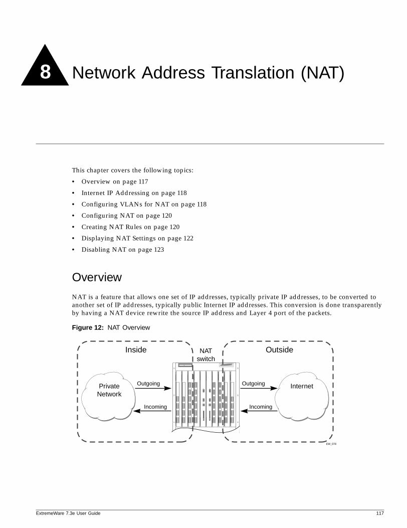
8 Network Address Translation (NAT)
ExtremeWare 7
This chapter covers the following topics:
• Overview on page 117
• Internet IP Addressing on page 118
• Configuring VLANs for NAT on page 118
• Configuring NAT on page 120
• Creating NAT Rules on page 120
• Displaying NAT Settings on page 122
• Disabling NAT on page 123
Overview
NAT is a feature that allows one set of IP addresses, typically private IP addresses, to be converted to another set of IP addresses, typically public Internet IP addresses. This conversion is done transparently by having a NAT device rewrite the source IP address and Layer 4 port of the packets.
Figure 12: NAT Overview
EW_078
NATswitch
Outgoing
Incoming
Outgoing
Incoming
Internet
Inside Outside
PrivateNetwork
.3e User Guide 117
Network Address Translation (NAT)
You can configure NAT to conserve IP address space by mapping a large number of inside (private) addresses to a much smaller number of outside (public) addresses.
In implementing NAT, you must configure at least two separate VLANs involved. One VLAN is configured as inside, and corresponds to the private IP addresses you would like to translate into other IP addresses. The other type of VLAN is configured as outside, which corresponds to the public (probably Internet) IP addresses you want the inside addresses translated to. The mappings between inside and outside IP addresses are done via rules that specify the IP subnets involved and the algorithms used to translate the addresses.
NOTE
The NAT modes in ExtremeWare support translating traffic that initiates only from inside addresses.
NAT rules are associated with a single outside VLAN. Multiple rules per outside VLAN are allowed. The rules take effect in the order they are displayed using the show nat command. Any number of inside VLANs can use a single outside VLAN, assuming that you have created proper rules. Similarly, a single inside VLAN can use any number of different outside VLANs, assuming that the rules and routing are set up properly.
Both TCP and UDP have layer 4 port numbers ranging from 1 to 65535. These layer 4 ports, in combination with the IP addresses, form a unique identifier which allows hosts (as well as the NAT switch) to distinguish between separate conversations. NAT operates by replacing the inside IP packet’s source IP and layer 4 port with an outside IP and layer 4 port. The NAT switch maintains a connection table to map the return packets on the outside VLAN back into their corresponding inside sessions.
Internet IP Addressing
When implementing NAT in an Internet environment, it is strongly recommended that you use one of the reserved private IP address ranges for your inside IP addresses. These ranges have been reserved specifically for networks not directly attached to the Internet. Using IP addresses within these ranges prevents addressing conflicts with public Internet sites to which you want to connect. The ranges are as follows:
• 10.0.0.0/8—Reserved Class A private address space
• 172.16.0.0/12—Reserved Class B private address space
• 192.168.0.0/16—Reserved Class C private address space
Configuring VLANs for NAT
You must configure each VLAN participating in NAT as either an inside or outside VLAN. To configure a VLAN as an inside or outside VLAN, use the following command:
configure nat vlan <vlan name> [inside | outside | none]
When a VLAN is configured to be inside, traffic from that VLAN destined for an outside VLAN is translated only if it has a matching NAT rule. Any unmatched traffic will be routed normally and not be translated. Because all traffic destined for an outside VLAN runs through the central processing unit (CPU), it cannot run at line-rate.
118 ExtremeWare 7.3e User Guide
Configuring VLANs for NAT
ExtremeWare 7
When a VLAN is configured to be outside, it routes all traffic destined for inside VLANs. Because the traffic runs through the CPU, it cannot run at line-rate.
When a VLAN is configured to be none, all NAT functions are disabled and the VLAN operates normally.
Below is a set of example ACL rules to deny outside traffic. These examples assume the inside network is 192.168.1.0/24 and the outside VLAN is on port 1.
create access-list deny_ip ip destination 192.168.1.0/24 source any deny ports 1create access-list deny_icmp icmp destination 192.168.1.0/24 source any type any code any deny ports 1
NAT ModesThere are 4 different modes used to determine how the outside IP addresses and layer 4 ports are assigned.
• Static mapping
• Dynamic mapping
• Port-mapping
• Auto-constraining
Static Mapping
When static mapping is used, each inside IP address uses a single outside IP address. The layer 4 ports are not changed, only the IP address is rewritten. Because this mode requires a 1:1 mapping of internal to external addresses, it does not make efficient use of the external address space. However, it is useful when you have a small number of hosts that need to have their IP addresses rewritten without conflicting with other hosts. Because this mode does not rely on layer 4 ports, ICMP traffic is translated and allowed to pass.
Dynamic Mapping
Dynamic mapping is similar to static mapping in that the layer 4 ports are not rewritten during translation. Dynamic mapping is different in that the number of inside hosts can be greater than the number of outside hosts. The outside IP addresses are allocated on a first-come, first-serve basis to the inside IP addresses. When the last session for a specific inside IP address closes, that outside IP address can be used by other hosts. Since this mode does not rely on layer 4 ports, ICMP traffic is translated and allowed to pass.
Port-mapping
Port-mapping gives you the most efficient use of the external address space. As each new connection is initiated from the inside, the NAT device picks the next available source layer 4 port on the first available outside IP address. When all ports on a given IP address are in use, the NAT device uses ports off of the next outside IP address. Some systems reserve certain port ranges for specific types of traffic, so it is possible to map specific source layer 4 port ranges on the inside to specific outside source ranges. However, this may cause a small performance penalty. In this case, you would need to make several rules using the same inside and outside IP addresses, one for each layer 4 port range. ICMP traffic is not translated in this mode. You must add a dynamic NAT rule for the same IP address range to allow for ICMP traffic.
.3e User Guide 119
Network Address Translation (NAT)
Auto-constraining
The auto-constraining algorithm for port-mapping limits the number of outside layer 4 ports a single inside host can use simultaneously. The limitation is based on the ratio of inside to outside IP addresses. The outside IP address and layer 4 port space is evenly distributed to all possible inside hosts. This guarantees that no single inside host can prevent other traffic from flowing through the NAT device. Because of the large number of simultaneous requests that can be made from a web browser, it is not recommended that this mode be used when a large number of inside hosts are being translated to a small number of outside IP addresses. ICMP traffic is not translated in this mode. You must add a dynamic NAT rule for the same IP address range to allow for ICMP traffic.
Configuring NAT
The behavior of NAT is determined by the rules you create to translate the IP addresses. You must attach each rule to a specific VLAN. All rules are processed in order. The options specified on the NAT rule determine the algorithm used to translate the inside IP addresses to the outside IP addresses. For outgoing (inside to outside) packets, the first rule to match is processed. All following rules are ignored. All return packets must arrive on the same outside VLAN on which the session went out. For most configurations, make sure that the outside IP addresses specified in the rule are part of the outside VLAN’s subnet range, so that the switch can proxy the address resolution protocol (ARP) for those addresses.
To enable NAT functionality, use the following command:
enable nat
Creating NAT Rules
This section describes how to configure the various types of NAT (static, dynamic, portmap, and auto-constrain). In the examples in this section, advanced port and destination matching options have been removed. For information on how to use some of the more advanced rule matching features, see “Advanced Rule Matching” on page 122.
Creating Static and Dynamic NAT Rules
To create static or dynamic NAT rules, use this command:
configure nat add vlan <vlan name> map source [any | <source_ipaddress>/<mask>] {l4-port [any | <port> {- <port>}]} {destination <dest_ipaddress>/<mask> {l4-port [any | <port> {- <port>}]}} to <ip address> [/<mask> | - <ip address>] [tcp | udp | both] [portmap {<min> - <max>} | auto-constrain]
This is the simplest NAT rule. You specify the outside vlan name, and a subnet of inside IP addresses, which get translated to the outside IP address using the specified mode (static in this case). For the outside IP addresses, you can either specify an IP address and netmask or a starting and ending IP range to determine the IP addresses the switch will translate the inside IP addresses to. If the netmask for both the source and NAT addresses is /32, the switch will use static NAT translation. If the netmask for both the source and NAT addresses are not both /32, the switch will use dynamic NAT translation.
120 ExtremeWare 7.3e User Guide
Creating NAT Rules
ExtremeWare 7
Static NAT Rule Example
configure nat add out_vlan_1 map source 192.168.1.12/32 to 216.52.8.32/32
Dynamic NAT Rule Example
configure nat add out_vlan_1 map source 192.168.1.0/24 to 216.52.8.1 - 216.52.8.31
Creating Portmap NAT Rules
To configure portmap NAT rules, use this command:
configure nat add vlan <vlan name> map source [any | <source_ipaddress>/<mask>] {l4-port [any | <port> {- <port>}]} {destination <dest_ipaddress>/<mask> {l4-port [any | <port> {- <port>}]}} to <ip address> [/<mask> | - <ip address>] [tcp | udp | both] [portmap {<min> - <max>} | auto-constrain]
The addition of an L4 protocol name and the portmap keyword tells the switch to use portmap mode. Optionally, you may specify the range of L4 ports the switch chooses on the translated IP addresses, but there is a performance penalty for doing this. Remember that portmap mode will only translate TCP and/or UDP, so a dynamic NAT rule must be specified after the portmap rule in order to allow ICMP packets through without interfering with the portmapping.
Portmap NAT Rule Example
configure nat add out_vlan_2 map source 192.168.2.0/25 to 216.52.8.32 /28 both portmap
Portmap Min-Max Example
configure nat add out_vlan_2 map source 192.168.2.128/25 to 216.52.8.64/28 tcp portmap 1024 - 8192
Creating Auto-Constrain NAT Rules
To create auto-constrain NAT rules, use the following command:
configure nat add vlan <vlan name> map source [any | <source_ipaddress>/<mask>] {l4-port [any | <port> {- <port>}]} {destination <dest_ipaddress>/<mask> {l4-port [any | <port> {- <port>}]}} to <ip address> [/<mask> | - <ip address>] [tcp | udp | both] [portmap {<min> - <max>} | auto-constrain]
This rule uses auto-constrain NAT. Remember that each inside IP address will be restricted in the number of simultaneous connections. Most installations should use portmap mode.
Auto-Constrain Example
configure nat add out_vlan_3 map source 192.168.3.0/24 to 216.52.8.64/32 both auto-constrain
.3e User Guide 121
Network Address Translation (NAT)
Advanced Rule Matching
By default, NAT rules only match connections based on the source IP address of the outgoing packets. Using the L4-port and destination keywords, you can further limit the scope of the NAT rule so that it only applied to specific TCP/UDP layer 4 port numbers, or specific outside destination IP addresses.
NOTE
Once a single rule is matched, no other rules are processed.
Destination Specific NAT
configure nat add vlan <vlan name> map source [any | <source_ipaddress>/<mask>] {l4-port [any | <port> {- <port>}]} {destination <dest_ipaddress>/<mask> {l4-port [any | <port> {- <port>}]}} to <ip address> [/<mask> | - <ip address>] [tcp | udp | both] [portmap {<min> - <max>} | auto-constrain]
The addition of the destination optional keyword after the source IP address and mask allows the NAT rule to be applied to only packets with a specific destination IP address.
L4-Port Specific NAT
The addition of the L4-port optional keyword after the source IP address and mask allows the NAT rule to be applied to only packets with a specific L4 source or destination port. If you use the L4-port command after the source IP/mask, the rule will only match if the port(s) specified are the source L4-ports. If you use the L4-port command after the destination IP/mask, the rule will only match if the port(s) specified are the destination L4-ports. Both options may be used together to further limit the rule.
Configuring Time-outsWhen an inside host initiates a session, a session table entry is created. Depending on the type of traffic or the current TCP state, the table entries time out after the configured time-out expires.
Displaying NAT Settings
To display NAT rules, use the following command:
show nat {timeout | stats | connections | rules {vlan <outside_vlan>}}
This command displays the NAT rules for a specific VLAN. Rules are displayed in the order they are processed, starting with the first one.
To display NAT traffic statistics, use the following command:
show nat stats
This command displays statistics for the NAT traffic, and includes:
• The number of rules
• The number of current connections
• The number of translated packets on the inside and outside VLANs
122 ExtremeWare 7.3e User Guide
Disabling NAT
ExtremeWare 7
• Information on missed translations
To display NAT connection information, use the following command:
show nat connections
This command displays the current NAT connection table, including source IP/layer 4 port mappings from inside to outside.
Disabling NAT
To disable NAT, use the following command:
disable nat
.3e User Guide 123

Network Address Translation (NAT)
124 ExtremeWare 7.3e User Guide
9 Status Monitoring and Statistics
ExtremeWare 7
This chapter describes the following topics:
• Status Monitoring on page 125
• Port Statistics on page 125
• Port Errors on page 126
• Port Monitoring Display Keys on page 127
• Setting the System Recovery Level on page 128
• Event Management System/Logging on page 128
• RMON on page 140
Viewing statistics on a regular basis allows you to see how well your network is performing. If you keep simple daily records, you will see trends emerging and notice problems arising before they cause major network faults. In this way, statistics can help you get the best out of your network.
Status Monitoring
The status monitoring facility provides information about the switch. This information may be useful for your technical support representative if you have a problem. ExtremeWare includes many show commands that display information about different switch functions and facilities.
NOTE
For more information about show commands for a specific ExtremeWare feature, see the appropriate chapter in this guide.
Port Statistics
ExtremeWare provides a facility for viewing port statistic information. The summary information lists values for the current counter against each port on each operational module in the system, and it is refreshed approximately every 2 seconds. Values are displayed to nine digits of accuracy.
To view port statistics, use the following command:
.3e User Guide 125
Status Monitoring and Statistics
show ports {mgmt | <portlist> | vlan <vlan name>} stats {cable-diagnostics}
The following port statistic information is collected by the switch:
• Link Status—The current status of the link. Options are:
— Ready (the port is ready to accept a link).
— Active (the link is present at this port).
— Chassis (the link is connected to a Summit Virtual Chassis). This status is available on the Summit 200 and 300 models.
• Transmitted Packet Count (Tx Pkt Count)—The number of packets that have been successfully transmitted by the port.
• Transmitted Byte Count (Tx Byte Count)—The total number of data bytes successfully transmitted by the port.
• Received Packet Count (Rx Pkt Count)—The total number of good packets that have been received by the port.
• Received Byte Count (RX Byte Count)—The total number of bytes that were received by the port, including bad or lost frames. This number includes bytes contained in the Frame Check Sequence (FCS), but excludes bytes in the preamble.
• Received Broadcast (RX Bcast)—The total number of frames received by the port that are addressed to a broadcast address.
• Received Multicast (RX Mcast)—The total number of frames received by the port that are addressed to a multicast address.
Port Errors
The switch keeps track of errors for each port.
To view port transmit errors, use the following command:
show ports {mgmt | <portlist>| vlan <vlan name>} txerrors
The managment port option (mgmt) is only available on switches with a managment port, such as the Summit 400.
The following port transmit error information is collected by the system:
• Port Number
• Link Status—The current status of the link. Options are:
— Ready (the port is ready to accept a link).
— Active (the link is present at this port).
• Transmit Collisions (TX Coll)—The total number of collisions seen by the port, regardless of whether a device connected to the port participated in any of the collisions.
• Transmit Late Collisions (TX Late Coll)—The total number of collisions that have occurred after the port’s transmit window has expired.
• Transmit Deferred Frames (TX Deferred)—The total number of frames that were transmitted by the port after the first transmission attempt was deferred by other network traffic.
• Transmit Errored Frames (TX Error)—The total number of frames that were not completely transmitted by the port because of network errors (such as late collisions or excessive collisions).
126 ExtremeWare 7.3e User Guide
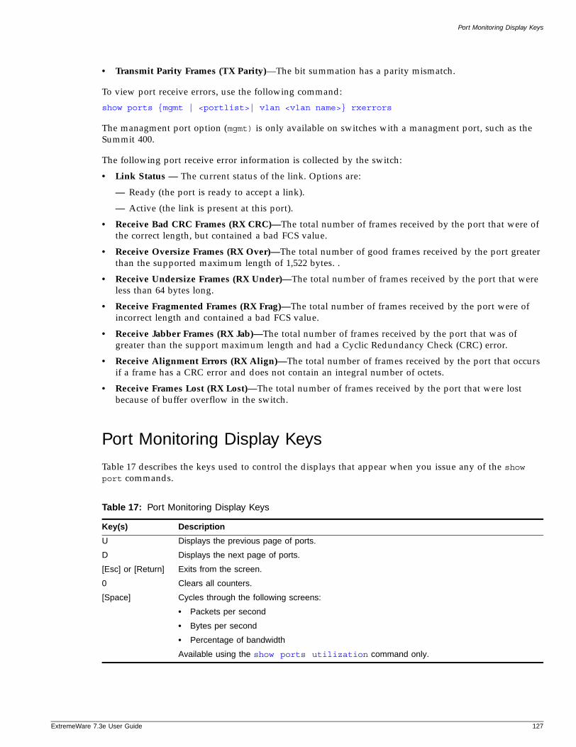
Port Monitoring Display Keys
ExtremeWare 7
• Transmit Parity Frames (TX Parity)—The bit summation has a parity mismatch.
To view port receive errors, use the following command:
show ports {mgmt | <portlist>| vlan <vlan name>} rxerrors
The managment port option (mgmt) is only available on switches with a managment port, such as the Summit 400.
The following port receive error information is collected by the switch:
• Link Status — The current status of the link. Options are:
— Ready (the port is ready to accept a link).
— Active (the link is present at this port).
• Receive Bad CRC Frames (RX CRC)—The total number of frames received by the port that were of the correct length, but contained a bad FCS value.
• Receive Oversize Frames (RX Over)—The total number of good frames received by the port greater than the supported maximum length of 1,522 bytes. .
• Receive Undersize Frames (RX Under)—The total number of frames received by the port that were less than 64 bytes long.
• Receive Fragmented Frames (RX Frag)—The total number of frames received by the port were of incorrect length and contained a bad FCS value.
• Receive Jabber Frames (RX Jab)—The total number of frames received by the port that was of greater than the support maximum length and had a Cyclic Redundancy Check (CRC) error.
• Receive Alignment Errors (RX Align)—The total number of frames received by the port that occurs if a frame has a CRC error and does not contain an integral number of octets.
• Receive Frames Lost (RX Lost)—The total number of frames received by the port that were lost because of buffer overflow in the switch.
Port Monitoring Display Keys
Table 17 describes the keys used to control the displays that appear when you issue any of the show port commands.
Table 17: Port Monitoring Display Keys
Key(s) Description
U Displays the previous page of ports.
D Displays the next page of ports.
[Esc] or [Return] Exits from the screen.
0 Clears all counters.
[Space] Cycles through the following screens:
• Packets per second
• Bytes per second
• Percentage of bandwidth
Available using the show ports utilization command only.
.3e User Guide 127
Status Monitoring and Statistics
Setting the System Recovery Level
You can configure the system to automatically reboot after a software task exception, using the following command:
configure sys-recovery-level [none | [all | critical] [ reboot ]]
Where the following is true:
• none—Configures the level to no recovery.
• all—Configures ExtremeWare to log an error into the syslog and automatically reboot the system after any task exception.
• critical—Configures ExtremeWare to log an error into the syslog and automatically reboot the system after a critical task exception.
• reboot—Reboots the switch.
The default setting is none.
Event Management System/Logging
The system responsible for logging and debugging was updated and enhanced. We use the general term, event, for any type of occurrence on a switch which could generate a log message, or require an action. For example, a link going down, a user logging in, a command entered on the command line, or the software executing a debugging statement, are all events that might generate a log message. The new system for saving, displaying, and filtering events is called the Event Management System (EMS). With EMS, you have a lot more options about which events generate log messages, where the messages are sent, and how they are displayed. Using EMS you can:
• send event messages to a number of logging targets (for example, syslog host and NVRAM)
• filter events on a per-target basis
— by component, subcomponent, or specific condition (for example, IGMP.Snooping messages, or the IP.Forwarding.SlowPathDrop condition)
— by match expression (for example, any messages containing the string “user5”)
— by matching parameters (for example, only messages with source IP addresses in the 10.1.2.0/24 subnet)
— by severity level (for example, only messages of severity critical, error, or warning)
• change the format of event messages (for example, display the date as “12-May-2003” or “2003-05-12”)
• display log messages in real-time, and filter the messages that are displayed, both on the console and from telnet sessions
• display stored log messages from the memory buffer or NVRAM
• upload event logs stored in memory to a TFTP server
• display counts of event occurrences, even those not included in filter
• display debug information, using a consistent configuration method
128 ExtremeWare 7.3e User Guide
Event Management System/Logging
ExtremeWare 7
Sending Event Messages to Log TargetsThere are five types of targets that can receive log messages:
• console display
• current session (telnet or console display)
• memory buffer (can contain 200-20,000 messages)
• NVRAM (messages remain after reboot)
• syslog host
The first four types of targets exist by default, but before enabling any syslog host, the host’s information needs to be added to the switch using the configure syslog command. Extreme Networks EPICenter can be a syslog target.
By default, the memory buffer and NVRAM targets are already enabled and receive messages. To start sending messages to the targets, use the following command:
enable log target [console-display | memory-buffer | nvram | session | syslog [<host name/ip> {:<udp-port>} [local0 ... local7]]]
Once enabled, the target receives the messages it is configured for. See the section “Target Configuration” for information on viewing the current configuration of a target. The memory buffer can only contain the configured number of messages, so the oldest message is lost when a new message arrives, and the buffer is full.
Use the following command to stop sending messages to the target:
disable log target [console-display | memory-buffer | nvram | session | syslog [<host name/ip> {:<udp-port>} [local0 ... local7]]]
NOTE
Refer to your UNIX documentation for more information about the syslog host facility.
Filtering Events Sent to TargetsNot all event messages are sent to every enabled target. Each target receives only the messages that it is configured for.
Target Configuration
To specify the messages to send to a enabled target, you will set a message severity level, a filter name, and a match expression. These items determine which messages are sent to the target. You can also configure the format of the messages in the targets. Each target has a default configuration that mimics the expected behavior of prior ExtremeWare releases. For example, the console display target is configured to get messages of severity info and greater, the NVRAM target gets messages of severity warning and greater, and the memory buffer target gets messages of severity debug-data and greater. All the targets are associated by default with a filter named DefaultFilter, that passes all events at or above the default severity threshold, like the behavior of earlier releases (the earlier releases had no filters). All the targets are also associated with a default match expression that matches any messages (the expression that matches any message is displayed as Match: (none) from the command line). And finally, each target has a format associated with it.
.3e User Guide 129
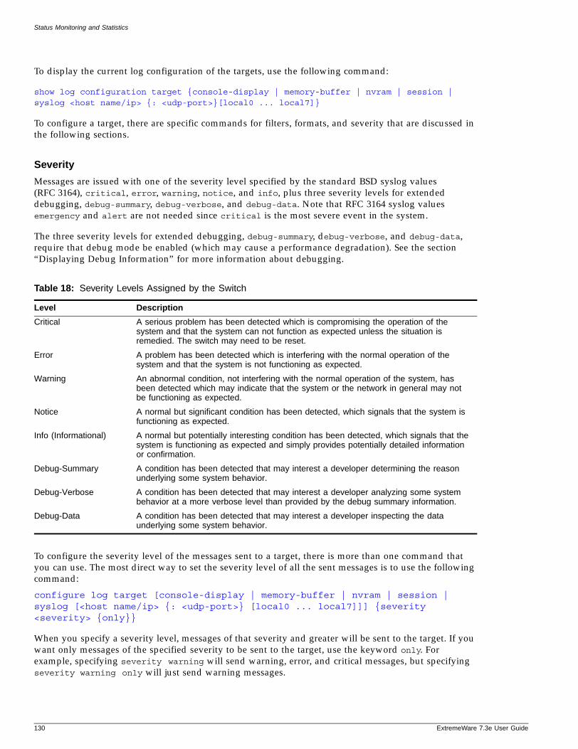
Status Monitoring and Statistics
To display the current log configuration of the targets, use the following command:
show log configuration target {console-display | memory-buffer | nvram | session | syslog <host name/ip> {: <udp-port>}[local0 ... local7]}
To configure a target, there are specific commands for filters, formats, and severity that are discussed in the following sections.
Severity
Messages are issued with one of the severity level specified by the standard BSD syslog values (RFC 3164), critical, error, warning, notice, and info, plus three severity levels for extended debugging, debug-summary, debug-verbose, and debug-data. Note that RFC 3164 syslog values emergency and alert are not needed since critical is the most severe event in the system.
The three severity levels for extended debugging, debug-summary, debug-verbose, and debug-data, require that debug mode be enabled (which may cause a performance degradation). See the section “Displaying Debug Information” for more information about debugging.
To configure the severity level of the messages sent to a target, there is more than one command that you can use. The most direct way to set the severity level of all the sent messages is to use the following command:
configure log target [console-display | memory-buffer | nvram | session | syslog [<host name/ip> {: <udp-port>} [local0 ... local7]]] {severity <severity> {only}}
When you specify a severity level, messages of that severity and greater will be sent to the target. If you want only messages of the specified severity to be sent to the target, use the keyword only. For example, specifying severity warning will send warning, error, and critical messages, but specifying severity warning only will just send warning messages.
Table 18: Severity Levels Assigned by the Switch
Level Description
Critical A serious problem has been detected which is compromising the operation of the system and that the system can not function as expected unless the situation is remedied. The switch may need to be reset.
Error A problem has been detected which is interfering with the normal operation of the system and that the system is not functioning as expected.
Warning An abnormal condition, not interfering with the normal operation of the system, has been detected which may indicate that the system or the network in general may not be functioning as expected.
Notice A normal but significant condition has been detected, which signals that the system is functioning as expected.
Info (Informational) A normal but potentially interesting condition has been detected, which signals that the system is functioning as expected and simply provides potentially detailed information or confirmation.
Debug-Summary A condition has been detected that may interest a developer determining the reason underlying some system behavior.
Debug-Verbose A condition has been detected that may interest a developer analyzing some system behavior at a more verbose level than provided by the debug summary information.
Debug-Data A condition has been detected that may interest a developer inspecting the data underlying some system behavior.
130 ExtremeWare 7.3e User Guide
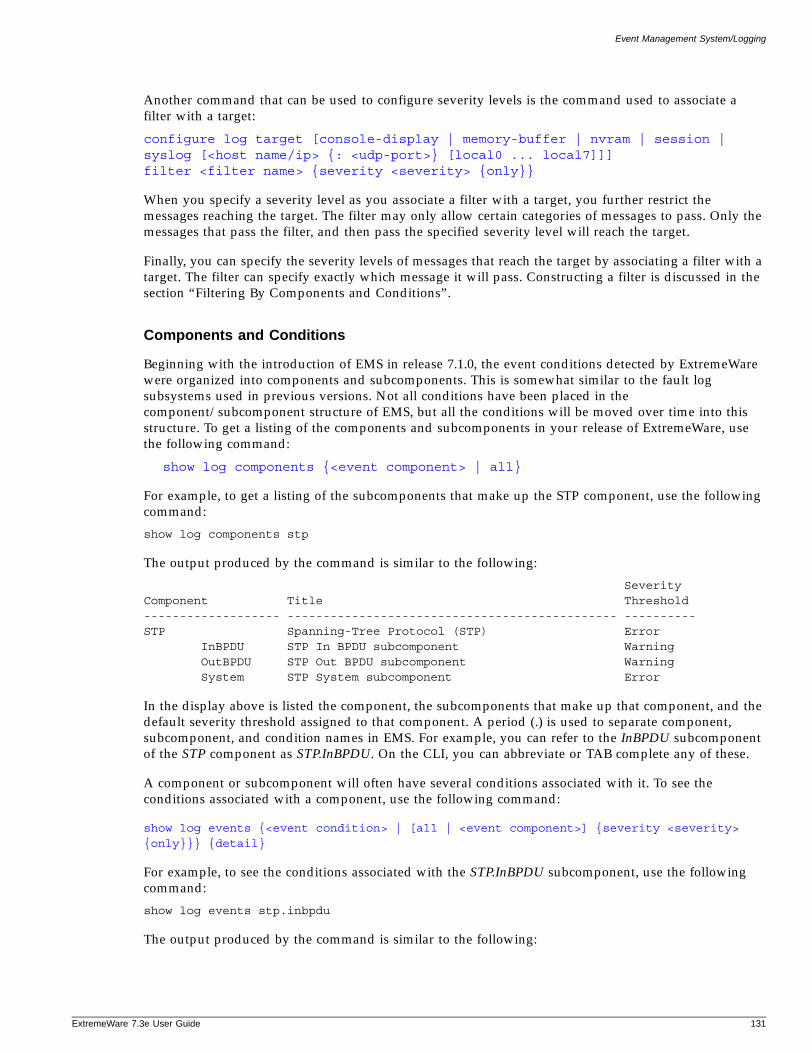
Event Management System/Logging
ExtremeWare 7
Another command that can be used to configure severity levels is the command used to associate a filter with a target:
configure log target [console-display | memory-buffer | nvram | session | syslog [<host name/ip> {: <udp-port>} [local0 ... local7]]] filter <filter name> {severity <severity> {only}}
When you specify a severity level as you associate a filter with a target, you further restrict the messages reaching the target. The filter may only allow certain categories of messages to pass. Only the messages that pass the filter, and then pass the specified severity level will reach the target.
Finally, you can specify the severity levels of messages that reach the target by associating a filter with a target. The filter can specify exactly which message it will pass. Constructing a filter is discussed in the section “Filtering By Components and Conditions”.
Components and Conditions
Beginning with the introduction of EMS in release 7.1.0, the event conditions detected by ExtremeWare were organized into components and subcomponents. This is somewhat similar to the fault log subsystems used in previous versions. Not all conditions have been placed in the component/subcomponent structure of EMS, but all the conditions will be moved over time into this structure. To get a listing of the components and subcomponents in your release of ExtremeWare, use the following command:
show log components {<event component> | all}
For example, to get a listing of the subcomponents that make up the STP component, use the following command:
show log components stp
The output produced by the command is similar to the following:
SeverityComponent Title Threshold------------------- ---------------------------------------------- ----------STP Spanning-Tree Protocol (STP) Error InBPDU STP In BPDU subcomponent Warning OutBPDU STP Out BPDU subcomponent Warning System STP System subcomponent Error
In the display above is listed the component, the subcomponents that make up that component, and the default severity threshold assigned to that component. A period (.) is used to separate component, subcomponent, and condition names in EMS. For example, you can refer to the InBPDU subcomponent of the STP component as STP.InBPDU. On the CLI, you can abbreviate or TAB complete any of these.
A component or subcomponent will often have several conditions associated with it. To see the conditions associated with a component, use the following command:
show log events {<event condition> | [all | <event component>] {severity <severity> {only}}} {detail}
For example, to see the conditions associated with the STP.InBPDU subcomponent, use the following command:
show log events stp.inbpdu
The output produced by the command is similar to the following:
.3e User Guide 131
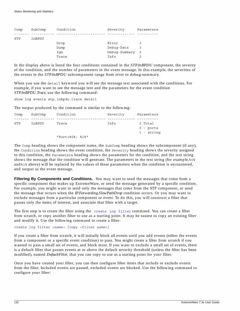
Status Monitoring and Statistics
Comp SubComp Condition Severity Parameters------- ----------- ----------------------- ------------- ----------STP InBPDU Drop Error 3 Dump Debug-Data 3 Ign Debug-Summary 2 Trace Info 2
In the display above is listed the four conditions contained in the STP.InBPDU component, the severity of the condition, and the number of parameters in the event message. In this example, the severities of the events in the STP.InBPDU subcomponent range from error to debug-summary.
When you use the detail keyword you will see the message text associated with the conditions. For example, if you want to see the message text and the parameters for the event condition STP.InBPDU.Trace, use the following command:
show log events stp.inbpdu.trace detail
The output produced by the command is similar to the following:
Comp SubComp Condition Severity Parameters------- ----------- ----------------------- ------------- ----------STP InBPDU Trace Info 2 Total 0 - ports 1 - string "Port=%0%: %1%"
The Comp heading shows the component name, the SubComp heading shows the subcomponent (if any), the Condition heading shows the event condition, the Severity heading shows the severity assigned to this condition, the Parameters heading shows the parameters for the condition, and the text string shows the message that the condition will generate. The parameters in the text string (for example,%0% and%1% above) will be replaced by the values of these parameters when the condition is encountered, and output as the event message.
Filtering By Components and Conditions. You may want to send the messages that come from a specific component that makes up ExtremeWare, or send the message generated by a specific condition. For example, you might want to send only the messages that come from the STP component, or send the message that occurs when the IP.Forwarding.SlowPathDrop condition occurs. Or you may want to exclude messages from a particular component or event. To do this, you will construct a filter that passes only the items of interest, and associate that filter with a target.
The first step is to create the filter using the create log filter command. You can create a filter from scratch, or copy another filter to use as a starting point. It may be easiest to copy an existing filter and modify it. Use the following command to create a filter:
create log filter <name> {copy <filter name>}
If you create a filter from scratch, it will initially block all events until you add events (either the events from a component or a specific event condition) to pass. You might create a filter from scratch if you wanted to pass a small set of events, and block most. If you want to exclude a small set of events, there is a default filter that passes events at or above the default severity threshold (unless the filter has been modified), named DefaultFilter, that you can copy to use as a starting point for your filter.
Once you have created your filter, you can then configure filter items that include or exclude events from the filter. Included events are passed, excluded events are blocked. Use the following command to configure your filter:
132 ExtremeWare 7.3e User Guide
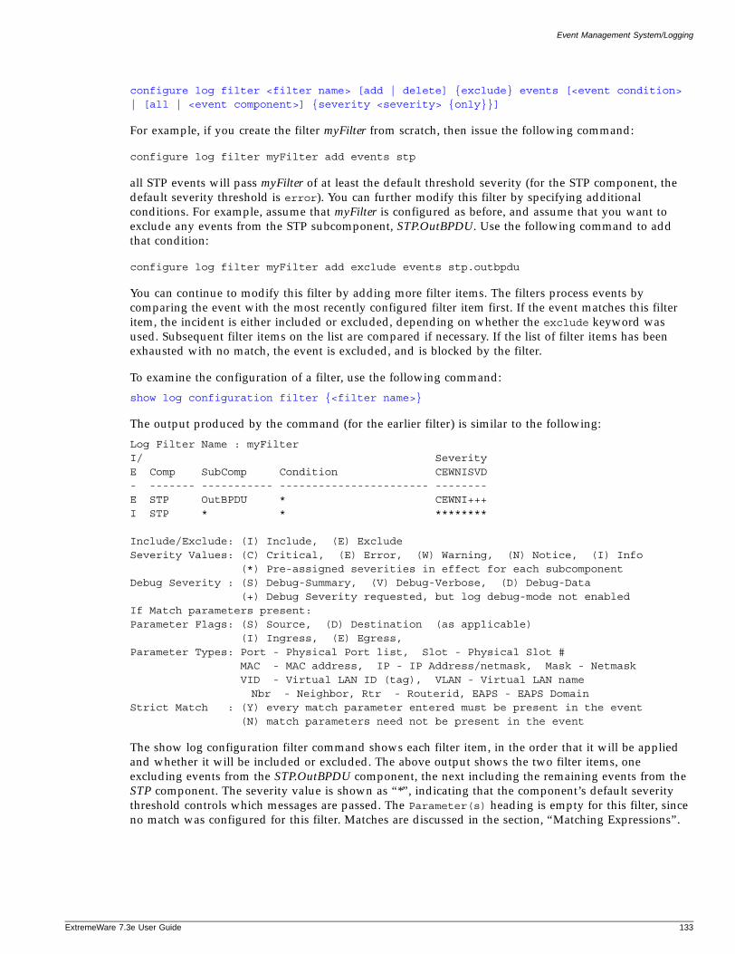
Event Management System/Logging
ExtremeWare 7
configure log filter <filter name> [add | delete] {exclude} events [<event condition> | [all | <event component>] {severity <severity> {only}}]
For example, if you create the filter myFilter from scratch, then issue the following command:
configure log filter myFilter add events stp
all STP events will pass myFilter of at least the default threshold severity (for the STP component, the default severity threshold is error). You can further modify this filter by specifying additional conditions. For example, assume that myFilter is configured as before, and assume that you want to exclude any events from the STP subcomponent, STP.OutBPDU. Use the following command to add that condition:
configure log filter myFilter add exclude events stp.outbpdu
You can continue to modify this filter by adding more filter items. The filters process events by comparing the event with the most recently configured filter item first. If the event matches this filter item, the incident is either included or excluded, depending on whether the exclude keyword was used. Subsequent filter items on the list are compared if necessary. If the list of filter items has been exhausted with no match, the event is excluded, and is blocked by the filter.
To examine the configuration of a filter, use the following command:
show log configuration filter {<filter name>}
The output produced by the command (for the earlier filter) is similar to the following:
Log Filter Name : myFilterI/ SeverityE Comp SubComp Condition CEWNISVD- ------- ----------- ----------------------- --------E STP OutBPDU * CEWNI+++I STP * * ********
Include/Exclude: (I) Include, (E) ExcludeSeverity Values: (C) Critical, (E) Error, (W) Warning, (N) Notice, (I) Info (*) Pre-assigned severities in effect for each subcomponentDebug Severity : (S) Debug-Summary, (V) Debug-Verbose, (D) Debug-Data (+) Debug Severity requested, but log debug-mode not enabledIf Match parameters present:Parameter Flags: (S) Source, (D) Destination (as applicable) (I) Ingress, (E) Egress, Parameter Types: Port - Physical Port list, Slot - Physical Slot # MAC - MAC address, IP - IP Address/netmask, Mask - Netmask VID - Virtual LAN ID (tag), VLAN - Virtual LAN name
Nbr - Neighbor, Rtr - Routerid, EAPS - EAPS DomainStrict Match : (Y) every match parameter entered must be present in the event (N) match parameters need not be present in the event
The show log configuration filter command shows each filter item, in the order that it will be applied and whether it will be included or excluded. The above output shows the two filter items, one excluding events from the STP.OutBPDU component, the next including the remaining events from the STP component. The severity value is shown as “*”, indicating that the component’s default severity threshold controls which messages are passed. The Parameter(s) heading is empty for this filter, since no match was configured for this filter. Matches are discussed in the section, “Matching Expressions”.
.3e User Guide 133
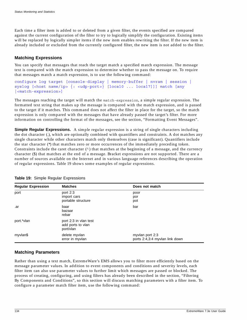
Status Monitoring and Statistics
Each time a filter item is added to or deleted from a given filter, the events specified are compared against the current configuration of the filter to try to logically simplify the configuration. Existing items will be replaced by logically simpler items if the new item enables rewriting the filter. If the new item is already included or excluded from the currently configured filter, the new item is not added to the filter.
Matching Expressions
You can specify that messages that reach the target match a specified match expression. The message text is compared with the match expression to determine whether to pass the message on. To require that messages match a match expression, is to use the following command:
configure log target [console-display | memory-buffer | nvram | session | syslog [<host name/ip> {: <udp-port>} [local0 ... local7]]] match [any |<match-expression>]
The messages reaching the target will match the match-expression, a simple regular expression. The formatted text string that makes up the message is compared with the match expression, and is passed to the target if it matches. This command does not affect the filter in place for the target, so the match expression is only compared with the messages that have already passed the target’s filter. For more information on controlling the format of the messages, see the section, “Formatting Event Messages”.
Simple Regular Expressions. A simple regular expression is a string of single characters including the dot character (.), which are optionally combined with quantifiers and constraints. A dot matches any single character while other characters match only themselves (case is significant). Quantifiers include the star character (*) that matches zero or more occurrences of the immediately preceding token. Constraints include the caret character (^) that matches at the beginning of a message, and the currency character ($) that matches at the end of a message. Bracket expressions are not supported. There are a number of sources available on the Internet and in various language references describing the operation of regular expressions. Table 19 shows some examples of regular expressions.
Matching Parameters
Rather than using a text match, ExtremeWare’s EMS allows you to filter more efficiently based on the message parameter values. In addition to event components and conditions and severity levels, each filter item can also use parameter values to further limit which messages are passed or blocked. The process of creating, configuring, and using filters has already been described in the section, “Filtering By Components and Conditions”, so this section will discuss matching parameters with a filter item. To configure a parameter match filter item, use the following command:
Table 19: Simple Regular Expressions
Regular Expression Matches Does not match
port port 2:3import carsportable structure
poorporpot
.ar baarbazaarrebar
bar
port.*vlan port 2:3 in vlan testadd ports to vlanport/vlan
myvlan$ delete myvlanerror in myvlan
myvlan port 2:3ports 2:4,3:4 myvlan link down
134 ExtremeWare 7.3e User Guide
Event Management System/Logging
ExtremeWare 7
configure log target [console-display | memory-buffer | nvram | session | syslog [<host name/ip> {: <udp-port>} [local0 ... local7]]] filter <filter name> {severity <severity> {only}}
Each event in ExtremeWare is defined with a message format and zero or more parameter types. The show log events detail command can be used to display event definitions (the event text and parameter types). Only those parameter types that are applicable given the events and severity specified are exposed on the CLI. The <value> depends on the parameter type specified. As an example, an event may contain a physical port number, a source MAC address, and a destination MAC address. To allow only those Bridging incidents, of severity notice and above, with a specific source MAC address, use the following command:
configure log filter myFilter add events bridge severity notice match source mac-address 00:01:30:23:C1:00
The string type is used to match a specific string value of an event parameter, such as a user name. A string can be specified as a simple regular expression.
Use the and keyword to specify multiple parameter type/value pairs that must match those in the incident. For example, to allow only those events with specific source and destination MAC addresses, use the following command:
configure log filter myFilter add events bridge severity notice match source mac-address 00:01:30:23:C1:00 and destination mac-address 01:80:C2:00:00:02
Match Versus Strict-Match. The match and strict-match keywords control the filter behavior for incidents whose event definition does not contain all the parameters specified in a configure log filter events match command. This is best explained with an example. Suppose an event in the XYZ component, named XYZ.event5, contains a physical port number, a source MAC address, but no destination MAC address. If you configure a filter to match a source MAC address and a destination MAC address, XYZ.event5 will match the filter when the source MAC address matches regardless of the destination MAC address, since the event contains no destination MAC address. If you specify the strict-match keyword, then the filter will never match event XYZ.event5, since this event does not contain the destination MAC address.
In other words, if the match keyword is specified, an incident will pass a filter so long as all parameter values in the incident match those in the match criteria, but all parameter types in the match criteria need not be present in the event definition.
Formatting Event Messages
Event messages are made up of a number of items. The individual items can be formatted, however, EMS does not allow you to vary the order of the items. To format the messages for a particular target, use the following command:
configure log target [console-display | memory-buffer | nvram | session | syslog [<host name/ip> {:<udp-port>} [local0 ... local7]]] format [timestamp [seconds | hundredths | none] | date [dd-mm-yyyy | dd-Mmm-yyyy | mm-dd-yyyy | Mmm-dd | yyyy-mm-dd | none] | severity [on | off]| event-name [component | condition | none | subcomponent] | host-name [on | off] | priority [on | off] | tag-id [on | off] | tag-name [on | off]
.3e User Guide 135
Status Monitoring and Statistics
| sequence-number [on | off] | process-name [on | off] | process-id [on | off] | source-function [on | off] | source-line [on | off]]
Using the default format for the session target, an example log message might appear as:
05/29/2003 12:15:25.00 <Warn:SNTP.RslvSrvrFail> The SNTP server parameter value (TheWrongServer.example.com) can not be resolved.
If you set the current session format using the following command:
configure log target session format date mm-dd-yyy timestamp seconds event-name component
The same example would appear as:
05/29/2003 12:16:36 <Warn:SNTP> The SNTP server parameter value (TheWrongServer.example.com) can not be resolved.
In order to provide some detailed information to technical support, you set the current session format using the following command:
configure log target session format date mmm-dd timestamp hundredths event-name condition source-line on process-name on
The same example would appear as:
May 29 12:17:20.11 SNTP: <Warn:SNTP.RslvSrvrFail> tSntpc: (sntpcLib.c:606) The SNTP server parameter value (TheWrongServer.example.com) can not be resolved.
Displaying Real-Time Log MessagesYou can configure the system to maintain a running real-time display of log messages on the console display or on a (telnet) session. To turn on the log display on the console, use the console-display option in the following command:
enable log target [console-display | memory-buffer | nvram | session | syslog [<host name/ip> {:<udp-port>} [local0 ... local7]]]
This setting may be saved to the FLASH configuration and will be restored on boot up (to the console-display session).
To turn on log display for the current session:
enable log target session
This setting only affects the current session, and is lost when you log off the session.
The messages that are displayed depend on the configuration and format of the target. See the section, “Filtering Events Sent to Targets”, for information on message filtering, and the section, “Formatting Event Messages”, for information on message formatting.
Displaying Events Logs
The log stored in the memory buffer and the NVRAM can be displayed on the current session (either the console display or telnet). Use the following command to display the log:
136 ExtremeWare 7.3e User Guide
Event Management System/Logging
ExtremeWare 7
show log {messages [memory-buffer | nvram]} {severity <severity> {only}} {starting [date <date> time <time> | date <date> | time <time>]} {ending [date <date> time <time> | date <date> | time <time>]} {match <match-expression>} {format <format>} {chronological}
There are many options you can use to select the log entries of interest. You can select to display only those messages that conform to the specified:
• severity
• starting and ending date and time
• match expression
The displayed messages can be formatted differently from the format configured for the targets, and you can choose to display the messages in order of newest to oldest, or in chronological order (oldest to newest).
Uploading Events Logs
The log stored in the memory buffer and the NVRAM can be uploaded to a TFTP server. Use the following command to upload the log:
upload log <host name/ip> <filename> {messages [memory-buffer | nvram]} {severity <severity> {only}} {starting [date <date> time <time> | date <date> | time <time>]} {ending [date <date> time <time> | date <date> | time <time>]} {match <match-expression>} {format <format>} {chronological}
You must specify the TFTP host and the filename to use in uploading the log. There are many options you can use to select the log entries of interest. You can select to upload only those messages that conform to the specified:
• severity
• starting and ending date and time
• match expression
The uploaded messages can be formatted differently from the format configured for the targets, and you can choose to upload the messages in order of newest to oldest, or in chronological order (oldest to newest).
Displaying Counts of Event Occurrences
EMS adds the ability to count the number of occurrences of events. Even when an event is filtered from all log targets, the event is counted. (The exception to this is events of any of the debug severities, which are only counted when the log debug mode is enabled.) To display the event counters, use the following command:
show log counters {<event condition> | [all | <event component>] {severity <severity> {only}}}
Two counters are displayed. One counter displays the number of times an event has occurred, and the other displays the number of times that notification for the event was made to the system for further processing. Both counters reflect totals accumulated since reboot or since the counters were cleared using the clear log counters or clear counters command.
.3e User Guide 137
Status Monitoring and Statistics
This command also displays an included count (the column titled In in the output). The reference count is the number of enabled targets receiving notifications of this event without regard to matching parameters.
The keywords included, notified, and occurred only display events with non-zero counter values for the corresponding counter.
Output of the command:
show log counters stp.inbpdu severity debug-summary
will be similar to the following:
Comp SubComp Condition Severity Occurred In Notified------- ----------- ----------------------- ------------- -------- -- --------STP InBPDU Drop Error 0 1 0 Ign Debug-Summary 0+ 0 0 Trace Info 0 0 0Occurred : # of times this event has occurred since last clear or rebootFlags : (+) Debug events are not counted while log debug-mode is disabledIn(cluded): # of enabled targets whose filter includes this eventNotified : # of times this event has occurred when 'Included' was non-zero
Output of the command:
show log counters stp.inbpdu.drop
will be similar to the following:
Comp SubComp Condition Severity Occurred In Notified------- ----------- ----------------------- ------------- -------- -- --------STP InBPDU Drop Error 0 1 0
Displaying Debug InformationBy default, a switch will not generate events of severity Debug-Summary, Debug-Verbose, and Debug-Data unless the switch is in debug mode. Debug mode causes a performance penalty, so it should only be enabled for specific cases where it is needed. To place the switch in debug mode, use the following command:
enable log debug-mode
Once debug mode is enabled, any filters configured for your targets will still affect which messages are passed on or blocked.
NOTE
Previous versions of ExtremeWare used the debug-trace command to enable debugging. Not all systems in ExtremeWare were converted to use EMS in the initial release. As a result, some debug information still requires you to use the corresponding debug-trace command. The show log component command displays the systems in your image that are part of EMS. Any systems in EMS will not have debug-trace commands, and vice-versa
138 ExtremeWare 7.3e User Guide
Event Management System/Logging
ExtremeWare 7
Compatibility with previous ExtremeWare commands
Since EMS provides much more functionality, there are a number of new commands introduced to support it. However, if you do not require the enhanced capabilities provided by EMS, you can continue to use many of the logging commands that existed in earlier versions of ExtremeWare. For consistency, the earlier commands are still supported. Listed below are earlier commands with their new command equivalents.
Enable / disable log display
The following commands related to the serial port console:
enable log display disable log display
are equivalent to using the console-display option in the following commands:
enable log target [console-display | memory-buffer | nvram | session | syslog [<host name/ip> {:<udp-port>} [local0 ... local7]]]
disable log target [console-display | memory-buffer | nvram | session | syslog [<host name/ip> {:<udp-port>} [local0 ... local7]]]
Note that the existing command enable log display applies only to the serial port console. Since the ability to display log messages on other sessions was added, the target name session was chosen. For clarity, the target name console-display was chosen to refer to the serial port console, previously referred to as simply display.
Configure log display
The following command related to the serial port console:
configure log display {<severity>}
is equivalent to:
configure log target console-display severity <severity>
Remote syslog commands
The following command related to remote syslog hosts:
configure syslog {add} <host name/ip> {: <udp-port>} [local0 ... local7] {<severity>}
is equivalent to the following two commands:
configure syslog add <hostname/IP> {: <udp-port>} [local0 ... local7]configure log target syslog <hostname/IP> {: <udp-port>} [local0 ... local7] severity <severity>
NOTE
Refer to your UNIX documentation for more information about the syslog host facility.
.3e User Guide 139
Status Monitoring and Statistics
Logging Configuration Changes
ExtremeWare allows you to record all configuration changes and their sources that are made using the CLI by way of telnet or the local console. The changes cause events that are logged to the target logs. Each log entry includes the user account name that performed the change and the source IP address of the client (if telnet was used). Configuration logging applies only to commands that result in a configuration change. To enable configuration logging, use the following command:
enable cli-config-logging
To disable configuration logging, use the following command:
disable cli-config-logging
CLI configuration logging is enabled by default.
RMON
Using the Remote Monitoring (RMON) capabilities of the switch allows network administrators to improve system efficiency and reduce the load on the network.
The following sections explain more about the RMON concept and the RMON features supported by the switch.
NOTE
You can only use the RMON features of the system if you have an RMON management application, and have enabled RMON on the switch.
About RMONRMON is the common abbreviation for the Remote Monitoring Management Information Base (MIB) system defined by the Internet Engineering Task Force (IETF) documents RFC 1271 and RFC 1757, which allows you to monitor LANs remotely.
A typical RMON setup consists of the following two components:
• RMON probe—An intelligent, remotely controlled device or software agent that continually collects statistics about a LAN segment or VLAN. The probe transfers the information to a management workstation on request, or when a predefined threshold is crossed.
• Management workstation—Communicates with the RMON probe and collects the statistics from it. The workstation does not have to be on the same network as the probe, and can manage the probe by in-band or out-of-band connections.
RMON Features of the SwitchThe IETF defines nine groups of Ethernet RMON statistics. The switch supports the following four of these groups:
• Statistics
• History
• Alarms
140 ExtremeWare 7.3e User Guide
RMON
ExtremeWare 7
• Events
This section describes these groups and discusses how they can be used.
Statistics
The RMON Ethernet Statistics group provides traffic and error statistics showing packets, bytes, broadcasts, multicasts, and errors on a LAN segment or VLAN.
Information from the Statistics group is used to detect changes in traffic and error patterns in critical areas of the network.
History
The History group provides historical views of network performance by taking periodic samples of the counters supplied by the Statistics group. The group features user-defined sample intervals and bucket counters for complete customization of trend analysis.
The group is useful for analysis of traffic patterns and trends on a LAN segment or VLAN, and to establish baseline information indicating normal operating parameters.
Alarms
The Alarms group provides a versatile, general mechanism for setting threshold and sampling intervals to generate events on any RMON variable. Both rising and falling thresholds are supported, and thresholds can be on the absolute value of a variable or its delta value. In addition, alarm thresholds can be autocalibrated or set manually.
Alarms inform you of a network performance problem and can trigger automated action responses through the Events group.
Events
The Events group creates entries in an event log and/or sends SNMP traps to the management workstation. An event is triggered by an RMON alarm. The action taken can be configured to ignore it, to log the event, to send an SNMP trap to the receivers listed in the trap receiver table, or to both log and send a trap. The RMON traps are defined in RFC 1757 for rising and falling thresholds.
Effective use of the Events group saves you time. Rather than having to watch real-time graphs for important occurrences, you can depend on the Event group for notification. Through the SNMP traps, events can trigger other actions, which provides a mechanism for an automated response to certain occurrences.
Configuring RMONRMON requires one probe per LAN segment, and standalone RMON probes traditionally have been expensive. Therefore, Extreme’s approach has been to build an inexpensive RMON probe into the agent of each system. This allows RMON to be widely deployed around the network without costing more than traditional network management. The switch accurately maintains RMON statistics at the maximum line rate of all of its ports.
For example, statistics can be related to individual ports. Also, because a probe must be able to see all traffic, a stand-alone probe must be attached to a nonsecure port. Implementing RMON in the switch means that all ports can have security features enabled.
.3e User Guide 141
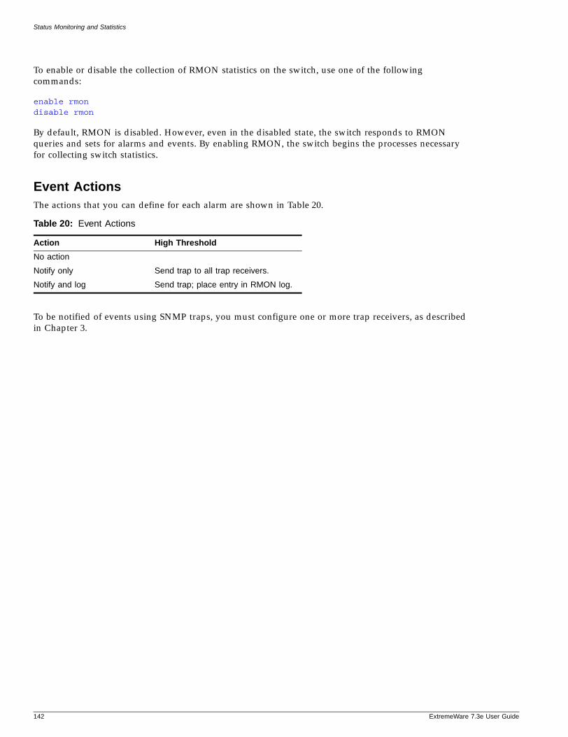
Status Monitoring and Statistics
To enable or disable the collection of RMON statistics on the switch, use one of the following commands:
enable rmon disable rmon
By default, RMON is disabled. However, even in the disabled state, the switch responds to RMON queries and sets for alarms and events. By enabling RMON, the switch begins the processes necessary for collecting switch statistics.
Event ActionsThe actions that you can define for each alarm are shown in Table 20.
To be notified of events using SNMP traps, you must configure one or more trap receivers, as described in Chapter 3.
Table 20: Event Actions
Action High Threshold
No action
Notify only Send trap to all trap receivers.
Notify and log Send trap; place entry in RMON log.
142 ExtremeWare 7.3e User Guide
10 Security
ExtremeWare 7
This chapter describes the following topics:
• Security Overview on page 143
• Network Access Security on page 143
— MAC-Based VLANs on page 144
— IP Access Lists (ACLs) on page 144
— MAC Address Security on page 153
— Network Login on page 156
— Unified Access Security on page 168
— Trusted Organizational Unique Identifier on page 168
• Trusted Organizational Unique Identifier on page 168
— Profile Assignment Example on page 194
— Denial of Service Protection on page 202
• Duplicate IP Protection on page 210
— Authenticating Users Using RADIUS or TACACS+ on page 211
— Configuring Timeout on page 219
• Unified Access MAC RADIUS on page 224
Security Overview
Extreme Networks products incorporate a number of features designed to enhance the security of your network. No one feature can insure security, but by using a number of features in concert, you can substantially improve the security of your network. The features described in this chapter are part of an overall approach to network security
Network Access Security
Network access security features control devices accessing your network. In this category are the following features:
.3e User Guide 143
Security
• MAC-Based VLANs
• IP Access Lists (ACLs)
• MAC Address Security
• Network Login
• Unified Access Security
MAC-Based VLANs
MAC-Based VLANs allow physical ports to be mapped to a VLAN based on the source MAC address learned in the FDB. This feature allows you to designate a set of ports that have their VLAN membership dynamically determined by the MAC address of the end station that plugs into the physical port. You can configure the source MAC address-to-VLAN mapping either offline or dynamically on the switch. For example, you could use this application for a roaming user who wants to connect to a network from a conference room. In each room, the user plugs into one of the designated ports on the switch and is mapped to the appropriate VLAN. Connectivity is maintained to the network with all of the benefits of the configured VLAN in terms of QoS, routing, and protocol support.
Detailed information about configuring and using MAC-based VLANs can be found in Chapter 5.
IP Access Lists (ACLs)
Each access control list (ACL) consists of an access mask that selects which fields of each incoming packet to examine, and a list of values to compare with the values found in the packet. Access masks can be shared multiple access control lists, using different lists of values to examine packets. The following sections describe how to use access control lists.
Access MasksThere are sixteen access masks available in the Summit 400-48t, depending on which features are enabled on the switch. Each access mask is created with a unique name and defines a list of fields that will be examined by any access control list that uses that mask (and by any rate limit that uses the mask).
To create an access mask, use the following command:
create access-mask <access-mask name> {dest-mac} {source-mac} {vlan} {tos |code-point} {ethertype} {ipprotocol} {dest-ip/<mask length>} {source-L4port | {icmp-type} {icmp-code}} {permit-established} {egresport} {ports} {precedence <number>}{vlan-pri}{vlan-pri-2bits}
You can also display or delete an access mask. To display information about an access mask, use the following command:
show access-mask {<name>}
To delete an access mask, use the following command:
delete access-mask <name>
144 ExtremeWare 7.3e User Guide
IP Access Lists (ACLs)
ExtremeWare 7
Access ListsAccess control lists are used to perform packet filtering and forwarding decisions on incoming traffic. Each packet arriving on an ingress port is compared to the access list in sequential order and is either forwarded to a specified QoS profile or dropped. These forwarded packets can also be modified by changing the 802.1p value and/or the DiffServ code point. Using access lists has no impact on switch performance.
The Summit “e” series switches support up to 16 access lists. Each entry that makes up an access list contains a unique name and specifies a previously created access mask. The access list also includes a list of values to compare with the incoming packets, and an action to take for packets that match. When you create an access list, you must specify a value for each of the fields that make up the access mask used by the list.
To create an access list, use the following command:
create access-list <name> access-mask <access-mask name> {dest-mac <dest_mac}
{source-mac <src_mac>} {vlan <name>} {ethertype [IP | ARP | <hex_value>]} {tos
<ip_precedence> | code-point <code_point>} {ipprotocol [tcp | udp | icmp | igmp |
<prococol_num>]} {dest-ip <dest_IP>/<mask length>} {dest-L4port <dest_port>}
{source-ip <src_IP>/<mask length>} {source-L4port <src_port> [permit {qosprofile
<qosprofile>} {set code-point <code_point>} {set dot1p <dot1p_value} |
permit-established | deny]{vlan-pri}{vlan-pri-2bits}
NOTE
The parameters of the create access list command must match identically to the parameters of the create access-mask. The order of the parameters is also important. If the parameter are out-of-order, many of the options become unavailable to the user.
For packets that match a particular access list, you can specify the following actions:
• Deny—Matching packets are not forwarded.
• Permit-established—Drop the packet if it would initiate a new TCP session (see, “The permit-established Keyword” on page 147).
• Permit—Forward the packet. You can send the packet to a particular QoS profile, and modify the packet’s 802.1p value and/or DiffServ code point.
If a packet matches more than one access list, the switch uses the following rules to govern the actions of the packet:
• If the actions specified by the matching ACLs do not conflict, all of the actions are carried out.
• If the actions conflict, the associated access mask precedence determines the course of action. The access list with the highest precedence access-mask prevails.
To display information about one or more access lists, use the following command:
show access-list {<name> | port <portlist>}
To delete an access list, use the following command:
delete access-list <name>
.3e User Guide 145
Security
Rate LimitsRate limits are almost identical to access control lists. Incoming packets that match a rate limit access control list are allowed as long as they do not exceed a pre-defined rate. Excess packets are either dropped, or modified by resetting their DiffServ code point.
Each entry that makes up a rate limit contains a unique name and specifies a previously created access mask. Like an access list, a rate limit includes a list of values to compare with the incoming packets and an action to take for packets that match. Additionally, a rate limit specifies an action to take when matching packets arrive at a rate above the limit you set. When you create a rate limit, you must specify a value for each of the fields that make up the access mask used by the list.
To create a rate limit rule, use the following command:
create rate-limit <rule_name> access-mask <access-mask name> {dest-mac <dest_mac>} {source-mac <scr_mac>} {vlan <name>} {ethertype [IP | ARP | <hex_value>]} {tos <ip_precedence> | code-point <code_point>} {ipprotocol [tcp | udp | icmp | igmp | <prococol_num>]} {dest-ip <dest_IP>/<mask length>} {dest-L4port <dest_port>} {source-ip <src_IP>/<mask length>} {source-L4port <src_port> [permit {qosprofile <qosprofile>} {set code-point <code_point>} {set dot1p <dot1p_value} limit <rate_in_Mbps> {exceed-action [drop | set code-point <code_point>]} {vlan-pri}{vlan-pri-2bits}
NOTE
Unlike an access list, a rate limit can only be applied to a single port. Each port will have its own rate limit defined separately.
On a 100 Mbps port (100BASE-TX), you can configure the rate limit value in the range from 1 Mbps to 100 Mbps in 1 Mbps increments, which is to say, the rate limit value can be set at 1, 2, 3, 4 … 100 Mbps.
On a 1000 Mbps port (Gigabit Ethernet uplink port), you can configure the rate limit value in the range from 8 Mbps to 1000 Mbps in increments of 8 Mbps, which is to say the rate limit value can be set at 8, 16, 24, 32 … 1000 Mbps.
NOTE
The rate limit specified in the command line does not precisely match the actual rate limit imposed by the hardware, due to hardware constraints. See the release notes for the exact values of the actual rate limits, if required for your implementation.
For packets that match a particular list, and arrive at a rate below the limit, you can specify the following action:
• Permit—Forward the packet. You can send the packet to a particular QoS profile, and modify the packet’s 802.1p value and/or DiffServ code point.
For packets that match a particular list and arrive at a rate that exceeds the limit, you can specify the following actions:
• Drop—Drop the packets. Excess packets are not forwarded.
• Permit with rewrite—Forward the packet, but modify the packet’s DiffServ code point.
146 ExtremeWare 7.3e User Guide
IP Access Lists (ACLs)
ExtremeWare 7
How Access Control Lists Work
When a packet arrives on an ingress port, the fields of the packet corresponding to an access mask are compared with the values specified by the associated access lists to determine a match.
It is possible that a packet can match more than one access control list. If the resulting actions of all the matches do not conflict, they are all be carried out. If there is a conflict, the actions of the access list using the higher precedence access mask are applied. When a match is found, the packet is processed. If the access list is of type deny, the packet is dropped. If the list is of type permit, the packet is forwarded. A permit access list can also apply a QoS profile to the packet and modify the packet’s 802.1p value and the DiffServ code point.
Access Mask Precedence Numbers
The access mask precedence number determines the order in which each rule is examined by the switch and is optional. Access control list entries are evaluated from highest precedence to lowest precedence. Precedence numbers range from 1 to 25,600, with the number 1 having the highest precedence, but an access mask without a precedence specified has a higher precedence than any access mask with a precedence specified. The first access mask defined without a specified precedence has the highest precedence. Subsequent masks without a specified precedence have a lower precedence, and so on.
Specifying a Default RuleYou can specify a default access control list to define the default access to the switch. You should use an access mask with a low precedence for the default rule access control list. If no other access control list entry is satisfied, the default rule is used to determine whether the packet is forwarded or dropped. If no default rule is specified, the default behavior is to forward the packet.
NOTE
If your default rule denies traffic, you should not apply this rule to the Summit 400-48t port used as a management port.
Once the default behavior of the access control list is established, you can create additional entries using precedence numbers.
The permit-established KeywordThe permit-established keyword is used to directionally control attempts to open a TCP session. Session initiation can be explicitly blocked using this keyword.
The permit-established keyword denies the access control list. Having a permit-established access control list blocks all traffic that matches the TCP source/destination, and has the SYN=1 and ACK=0 flags set.
Adding Access Mask, Access List, and Rate Limit EntriesEntries can be added to the access masks, access lists, and rate limits. To add an entry, you must supply a unique name using the create command, and supply a number of optional parameters. For access lists and rate limits, you must specify an access mask to use. To modify an existing entry, you must delete the entry and retype it, or create a new entry with a new unique name.
.3e User Guide 147
Security
To add an access mask entry, use the following command:
create access-mask <name> ...
To add an access list entry, use the following command:
create access-list <name> ...
To add a rate limit entry, use the following command:
create rate-limit <name> ...
Maximum Entries
If you try to create an access mask when no more are available, the system will issue a warning message. Three access masks are constantly used by the system, leaving a maximum of 13 user-definable access masks. However, enabling some features causes the system to use additional access masks, reducing the number available.
For each of the following features that you enable, the system will use one access mask. When the feature is disabled, the mask will again be available. The features are:
• RIP
• IGMP or OSPF (both would share a single mask)
• DiffServ examination
• QoS monitor
The maximum number of access list allowed by the hardware is 254 for each block of eight 10/100 Mbps Ethernet ports and 126 for each Gbps Ethernet port, for a total of 1014 rules (254*3+126*2). Most user entered access list commands will require multiple rules on the hardware. For example, a global rule (an access control list using an access mask without “ports” defined), will require 5 rules, one for each of the 5 blocks of ports on the hardware.
The maximum number of rate-limiting rules allowed is 315 (63*5). This number is part of the total access control list rules (1014).
Deleting Access Mask, Access List, and Rate Limit EntriesEntries can be deleted from access masks, access lists, and rate limits. An access mask entry cannot be deleted until all the access lists and rate limits that reference it are also deleted.
To delete an access mask entry, use the following command:
delete access-mask <name>
To delete an access list entry, use the following command:
delete access-list <name>
To delete a rate limit entry, use the following command:
delete rate-limit <name>
Verifying Access Control List Configurations
To verify access control list settings, you can view the access list configuration.
To view the access list configuration use the following command:
148 ExtremeWare 7.3e User Guide
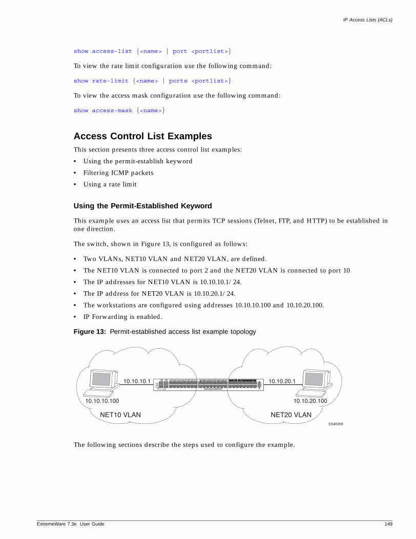
IP Access Lists (ACLs)
ExtremeWare 7
show access-list {<name> | port <portlist>}
To view the rate limit configuration use the following command:
show rate-limit {<name> | ports <portlist>}
To view the access mask configuration use the following command:
show access-mask {<name>}
Access Control List ExamplesThis section presents three access control list examples:
• Using the permit-establish keyword
• Filtering ICMP packets
• Using a rate limit
Using the Permit-Established Keyword
This example uses an access list that permits TCP sessions (Telnet, FTP, and HTTP) to be established in one direction.
The switch, shown in Figure 13, is configured as follows:
• Two VLANs, NET10 VLAN and NET20 VLAN, are defined.
• The NET10 VLAN is connected to port 2 and the NET20 VLAN is connected to port 10
• The IP addresses for NET10 VLAN is 10.10.10.1/24.
• The IP address for NET20 VLAN is 10.10.20.1/24.
• The workstations are configured using addresses 10.10.10.100 and 10.10.20.100.
• IP Forwarding is enabled.
Figure 13: Permit-established access list example topology
The following sections describe the steps used to configure the example.
ES4K009
10.10.10.1
10.10.10.100 10.10.20.100
10.10.20.1
NET20 VLANNET10 VLAN
.3e User Guide 149
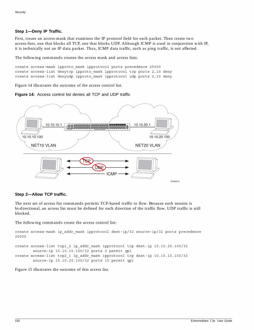
Security
Step 1—Deny IP Traffic.
First, create an access-mask that examines the IP protocol field for each packet. Then create two access-lists, one that blocks all TCP, one that blocks UDP. Although ICMP is used in conjunction with IP, it is technically not an IP data packet. Thus, ICMP data traffic, such as ping traffic, is not affected.
The following commands creates the access mask and access lists:
create access-mask ipproto_mask ipprotocol ports precedence 25000create access-list denytcp ipproto_mask ipprotocol tcp ports 2,10 denycreate access-list denyudp ipproto_mask ipprotocol udp ports 2,10 deny
Figure 14 illustrates the outcome of the access control list.
Figure 14: Access control list denies all TCP and UDP traffic
Step 2—Allow TCP traffic.
The next set of access list commands permits TCP-based traffic to flow. Because each session is bi-directional, an access list must be defined for each direction of the traffic flow. UDP traffic is still blocked.
The following commands create the access control list:
create access-mask ip_addr_mask ipprotocol dest-ip/32 source-ip/32 ports precedence 20000
create access-list tcp1_2 ip_addr_mask ipprotocol tcp dest-ip 10.10.20.100/32 source-ip 10.10.10.100/32 ports 2 permit qp1
create access-list tcp2_1 ip_addr_mask ipprotocol tcp dest-ip 10.10.10.100/32 source-ip 10.10.20.100/32 ports 10 permit qp1
Figure 15 illustrates the outcome of this access list.
ES4K010
10.10.10.1
10.10.10.100 10.10.20.100
10.10.20.1
NET20 VLANNET10 VLAN
TCP
UDP
ICMP
150 ExtremeWare 7.3e User Guide
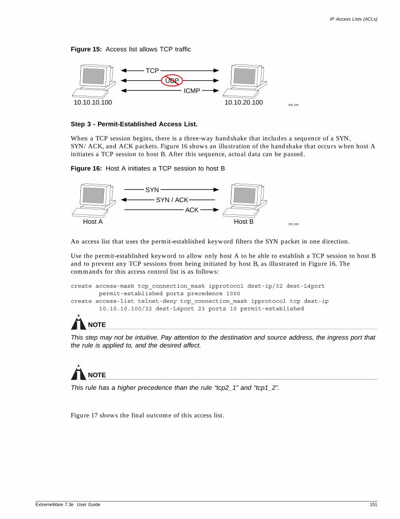
IP Access Lists (ACLs)
ExtremeWare 7
Figure 15: Access list allows TCP traffic
Step 3 - Permit-Established Access List.
When a TCP session begins, there is a three-way handshake that includes a sequence of a SYN, SYN/ACK, and ACK packets. Figure 16 shows an illustration of the handshake that occurs when host A initiates a TCP session to host B. After this sequence, actual data can be passed.
Figure 16: Host A initiates a TCP session to host B
An access list that uses the permit-established keyword filters the SYN packet in one direction.
Use the permit-established keyword to allow only host A to be able to establish a TCP session to host B and to prevent any TCP sessions from being initiated by host B, as illustrated in Figure 16. The commands for this access control list is as follows:
create access-mask tcp_connection_mask ipprotocol dest-ip/32 dest-L4port permit-established ports precedence 1000
create access-list telnet-deny tcp_connection_mask ipprotocol tcp dest-ip 10.10.10.100/32 dest-L4port 23 ports 10 permit-established
NOTE
This step may not be intuitive. Pay attention to the destination and source address, the ingress port that the rule is applied to, and the desired affect.
NOTE
This rule has a higher precedence than the rule “tcp2_1” and “tcp1_2”.
Figure 17 shows the final outcome of this access list.
EW_035
TCP
UDP
ICMP
10.10.10.100 10.10.20.100
EW_036
SYN
Host A Host B
SYN / ACK
ACK
.3e User Guide 151
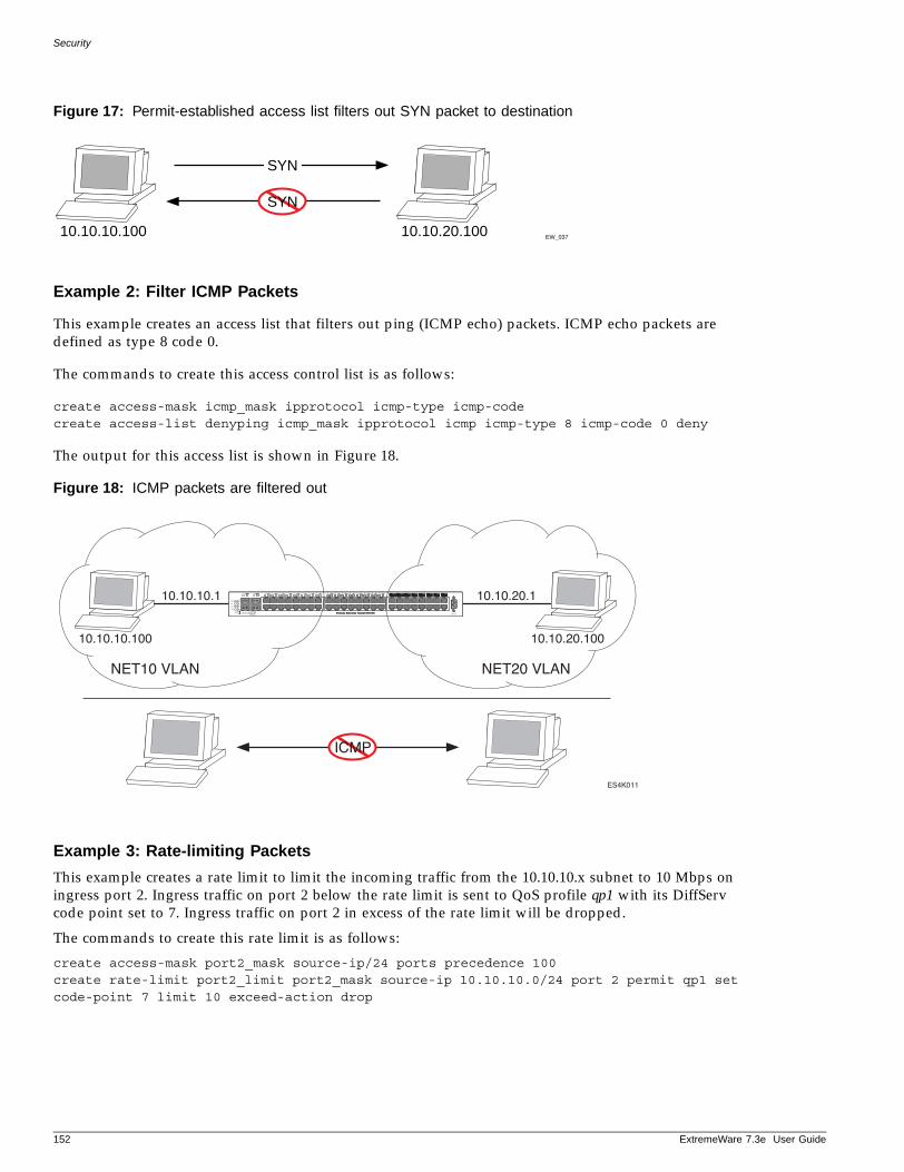
Security
Figure 17: Permit-established access list filters out SYN packet to destination
Example 2: Filter ICMP Packets
This example creates an access list that filters out ping (ICMP echo) packets. ICMP echo packets are defined as type 8 code 0.
The commands to create this access control list is as follows:
create access-mask icmp_mask ipprotocol icmp-type icmp-codecreate access-list denyping icmp_mask ipprotocol icmp icmp-type 8 icmp-code 0 deny
The output for this access list is shown in Figure 18.
Figure 18: ICMP packets are filtered out
Example 3: Rate-limiting Packets
This example creates a rate limit to limit the incoming traffic from the 10.10.10.x subnet to 10 Mbps on ingress port 2. Ingress traffic on port 2 below the rate limit is sent to QoS profile qp1 with its DiffServ code point set to 7. Ingress traffic on port 2 in excess of the rate limit will be dropped.
The commands to create this rate limit is as follows:
create access-mask port2_mask source-ip/24 ports precedence 100create rate-limit port2_limit port2_mask source-ip 10.10.10.0/24 port 2 permit qp1 set code-point 7 limit 10 exceed-action drop
EW_03710.10.10.100 10.10.20.100
SYN
SYN
ES4K011
10.10.10.1
10.10.10.100 10.10.20.100
10.10.20.1
NET20 VLANNET10 VLAN
ICMP
152 ExtremeWare 7.3e User Guide

MAC Address Security
ExtremeWare 7
MAC Address Security
The switch maintains a database of all media access control (MAC) addresses received on all of its ports. It uses the information in this database to decide whether a frame should be forwarded or filtered. MAC address security allows you to control the way the Forwarding Database (FDB) is learned and populated. By managing entries in the FDB, you can block, assign priority (queues), and control packet flows on a per-address basis.
MAC address security allows you to limit the number of dynamically-learned MAC addresses allowed per virtual port. You can also “lock” the FDB entries for a virtual port, so that the current entries will not change, and no additional addresses can be learned on the port.
NOTE
You can either limit dynamic MAC FDB entries, or lock down the current MAC FDB entries, but not both.
You can also prioritize or stop packet flows based on the source MAC address of the ingress VLAN or the destination MAC address of the egress VLAN.
Limiting Dynamic MAC AddressesYou can set a predefined limit on the number of dynamic MAC addresses that can participate in the network. After the FDB reaches the MAC limit, all new source MAC addresses are blackholed at both the ingress and egress points. These dynamic blackhole entries prevent the MAC addresses from learning and responding to Internet control message protocol (ICMP) and address resolution protocol (ARP) packets.
To limit the number of dynamic MAC addresses that can participate in the network, use the following command:
configure ports [<portlist> vlan <vlan name> | all] limit-learning <number>
This command specifies the number of dynamically-learned MAC entries allowed for these ports in this VLAN. The range is 0 to 500,000 addresses.
When the learned limit is reached, all new source MAC addresses are blackholed at the ingress and egress points. This prevent these MAC addresses from learning and responding to Internet control message protocol (ICMP) and address resolution protocol (ARP) packets.
Dynamically learned entries still get aged and can be cleared. If entries are cleared or aged out after the learning limit has been reached, new entries will then be able to be learned until the limit is reached again.
Permanent static and permanent dynamic entries can still be added and deleted using the create fdbentry vlan dynamic and delete fdbentry commands. These override any dynamically learned entries.
For ports that have a learning limit in place, the following traffic will still flow to the port:
• Packets destined for permanent MAC addresses and other non-blackholed MAC addresses
• Broadcast traffic
• EDP traffic
.3e User Guide 153
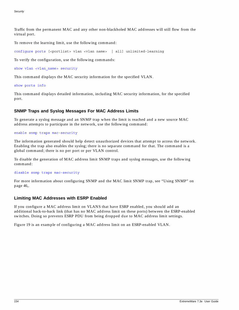
Security
Traffic from the permanent MAC and any other non-blackholed MAC addresses will still flow from the virtual port.
To remove the learning limit, use the following command:
configure ports [<portlist> vlan <vlan name> | all] unlimited-learning
To verify the configuration, use the following commands:
show vlan <vlan_name> security
This command displays the MAC security information for the specified VLAN.
show ports info
This command displays detailed information, including MAC security information, for the specified port.
SNMP Traps and Syslog Messages For MAC Address Limits
To generate a syslog message and an SNMP trap when the limit is reached and a new source MAC address attempts to participate in the network, use the following command:
enable snmp traps mac-security
The information generated should help detect unauthorized devices that attempt to access the network. Enabling the trap also enables the syslog; there is no separate command for that. The command is a global command; there is no per port or per VLAN control.
To disable the generation of MAC address limit SNMP traps and syslog messages, use the following command:
disable snmp traps mac-security
For more information about configuring SNMP and the MAC limit SNMP trap, see “Using SNMP” on page 46,.
Limiting MAC Addresses with ESRP Enabled
If you configure a MAC address limit on VLANS that have ESRP enabled, you should add an additional back-to-back link (that has no MAC address limit on these ports) between the ESRP-enabled switches. Doing so prevents ESRP PDU from being dropped due to MAC address limit settings.
Figure 19 is an example of configuring a MAC address limit on an ESRP-enabled VLAN.
154 ExtremeWare 7.3e User Guide
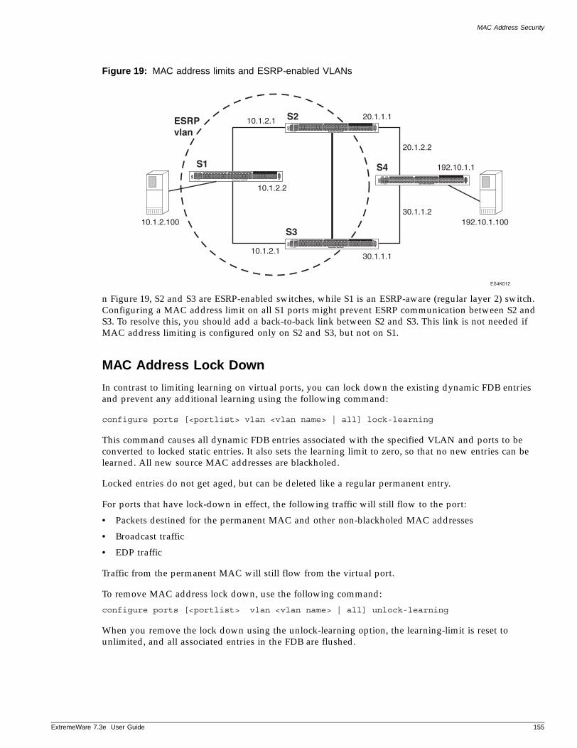
MAC Address Security
ExtremeWare 7
Figure 19: MAC address limits and ESRP-enabled VLANs
n Figure 19, S2 and S3 are ESRP-enabled switches, while S1 is an ESRP-aware (regular layer 2) switch. Configuring a MAC address limit on all S1 ports might prevent ESRP communication between S2 and S3. To resolve this, you should add a back-to-back link between S2 and S3. This link is not needed if MAC address limiting is configured only on S2 and S3, but not on S1.
MAC Address Lock Down
In contrast to limiting learning on virtual ports, you can lock down the existing dynamic FDB entries and prevent any additional learning using the following command:
configure ports [<portlist> vlan <vlan name> | all] lock-learning
This command causes all dynamic FDB entries associated with the specified VLAN and ports to be converted to locked static entries. It also sets the learning limit to zero, so that no new entries can be learned. All new source MAC addresses are blackholed.
Locked entries do not get aged, but can be deleted like a regular permanent entry.
For ports that have lock-down in effect, the following traffic will still flow to the port:
• Packets destined for the permanent MAC and other non-blackholed MAC addresses
• Broadcast traffic
• EDP traffic
Traffic from the permanent MAC will still flow from the virtual port.
To remove MAC address lock down, use the following command:
configure ports [<portlist> vlan <vlan name> | all] unlock-learning
When you remove the lock down using the unlock-learning option, the learning-limit is reset to unlimited, and all associated entries in the FDB are flushed.
ES4K012
ESRPvlan
10.1.2.100 192.10.1.10030.1.1.2
20.1.2.2
20.1.1.110.1.2.1
10.1.2.2
192.10.1.1S4S1
S2
S3
30.1.1.110.1.2.1
.3e User Guide 155
Security
Network Login
Network login controls the admission of user packets into a network by giving addresses only to users that are properly authenticated. Network login is controlled on a per port, per VLAN basis. When network login is enabled on a port in a VLAN, that port does not forward any packets until authentication takes place.
Network login is compatible with two types of authentication, web-based and 802.1x, and two different modes of operation, Campus mode and ISP mode. The authentication types and modes of operation can be used in any combination.
When web-based network login is enabled on a switch port, that port is placed into a non-forwarding state until authentication takes place. To authenticate, a user (supplicant) must open a web browser and provide the appropriate credentials. These credentials are either approved, in which case the port is placed in forwarding mode, or not approved, in which case the port remains blocked. Three failed login attempts disables the port for a configured length of time. User logout can be initiated by submitting a logout request or closing the logout window.
The following capabilities are included in network login:
• Web-based login using http and https available on each wired and wireless port
• 802.1x and web based network login supported on the same wired ports
• Multiple supplicants on each wired 10/100 and wireless port
• Single VLAN assignment for all users authenticated on a wired port
• Per-user VLAN support for all users authenticated on a wireless port
Web-Based and 802.1x Authentication
Authentication is handled as a web-based process, or as described in the IEEE 802.1x specification. Web-based network login does not require any specific client software and can work with any HTTP-compliant web browser. By contrast, 802.1x authentication may require additional software installed on the client workstation, making it less suitable for a user walk-up situation, such as a cyber-café or coffee shop.1 Extreme Networks supports a smooth transition from web-based to 802.1x authentication.
DHCP is required for web-based network login because the underlying protocol used to carry authentication request-response is HTTP. The client requires an IP address to send and receive HTTP packets. Before the client is authenticated, however, the only connection exists is to the authenticator. As a result, the authenticator must be furnished with a temporary DHCP server to distribute the IP address.
The switch responds to DHCP requests for unauthenticated clients when DHCP parameters such as dhcp-address-range and dhcp-options are configured on the Netlogin VLAN. The switch can also answer DHCP requests following authentication if DHCP is enabled on the specified VLAN. If netlogin clients are required to obtain DHCP leases from an external DHCP server elsewhere on the network, DHCP should not be enabled on the VLAN.
The DHCP allocation for network login has a short time default duration of 10 seconds and is intended to perform web-based network login only. As soon as the client is authenticated, it is deprived of this
1. A workstation running Windows XP supports 802.1x natively and does not require additional authentica-tion software.
156 ExtremeWare 7.3e User Guide
Network Login
ExtremeWare 7
address. The client must obtain a operational address from another DHCP server in the network. DHCP is not required for 802.1x, because 802.1x uses only Layer 2 frames (EAPOL).
URL redirection (applicable to web-based mode only) is a mechanism to redirect any HTTP request to the base URL of the authenticator when the port is in unauthenticated mode. In other words, when the user tries to log in to the network using the browser, the user is first redirected to the network login page. Only after a successful login is the user connected to the network.
Web-based and 802.1x authentication each have advantages and disadvantages, as summarized next.
Advantages of 802.1x Authentication:
• In cases where the 802.1x is natively supported, login and authentication happens transparently.
• Authentication happens at Layer 2. It does not involve getting a temporary IP address and subsequent release of the address to obtain a more permanent IP address.
• Allows for periodic, transparent, re-authorization of supplicants.
Disadvantages of 802.1x Authentication:
• 802.1x native support is available only on newer operating systems, such as Windows XP or Windows 2000 with service pack 4.
• 802.1x requires an EAP-capable RADIUS Server. Most current RADIUS servers support EAP.
Advantages of Web-based Authentication:
• Works with any operating system. There is need for special client side software.; only a web browser is needed.
Disadvantages of Web-based Authentication:
• The login process involves manipulation of IP addresses and must be done outside the scope of a normal computer login process. It is not tied to Windows login. The client must bring up a login page and initiate a login.
• Supplicants cannot be re-authenticated transparently. They cannot be re-authenticated from the authenticator side.
• Since wireless web-based network login supports only static WEP encryption, it is vulnerable to attack. Therefore, care should be taken when deploying this authentication mechanism. Using a secure web server (HTTP with SSL) alleviates some of this problem.
• This method is not as effective in maintaining privacy protection.
802.1x Authentication Methods
802.1x authentication methods govern interactions between the supplicant (client) and the authentication server. The most commonly used methods are Transport Layer Security (TLS) and Tunneled TLS (TTLS), which is a Funk/Certicom standards proposal.
TLS is the most secure of the currently available protocols, although TTLS is advertised to be as strong as TLS. Both TLS and TTLS are certificate-based and require a Public Key Infrastructure (PKI) that can issue, renew, and revoke certificates. TTLS is easier to deploy, as it requires only server certificates, by contrast with TLS, which requires client and server certificates. With TTLS, the client can use the MD5 mode of username/password authentication.
.3e User Guide 157
Security
If you plan to use 802.1x authentication, refer to the documentation for your particular RADIUS server, and 802.1x client on how to set up a PKI configuration.
Campus and ISP ModesNetwork login supports two modes of operation, Campus and ISP. Campus mode is intended for mobile users who tend to move from one port to another and connect at various locations in the network. ISP mode is meant for users who connect through the same port and VLAN each time (the switch functions as an ISP).
In campus mode, the clients are placed into a permanent VLAN following authentication with access to network resources. For wired ports, the port is moved from the temporary to the permanent VLAN.
In ISP mode, the port and VLAN remain constant. Before the supplicant is authenticated, the port is in an unauthenticated state. After authentication, the port forwards packets.
User Accounts
You can create two types of user accounts for authenticating network login users: netlogin-only enabled and netlogin-only disabled. A netlogin-only disabled user can log in using network login and can also access the switch using Telnet, SSH, or HTTP. A netlogin-only enabled user can only log in using network login and cannot access the switch using the same login.
Add the following line to the RADIUS server dictionary file for netlogin-only disabled users:
Extreme:Extreme-Netlogin-Only = Disabled
Add the following line to the RADIUS server dictionary file for netlogin-only enabled users:
Extreme:Extreme-Netlogin-Only = Enabled
Table 21 contains the Vendor Specific Attribute (VSA) definitions for web-based network login. The Extreme Network Vendor ID is 1916.
Interoperability RequirementsFor network login to operate, the user (supplicant) software and the authentication server must support common authentication methods. Not all combinations provide the appropriate functionality.
Table 21: VSA Definitions for Web-based and 802.1x Network Login
VSAAttribute Value Type Sent-in Description
Extreme-Netlogin-VLAN 203 String Access-Accept Name of destination VLAN after successful authentication (must already exist on switch).
Extreme-Netlogin-URL 204 String Access-Accept Destination web page after successful authentication.
Extreme-Netlogin-URL-Desc
205 String Access-Accept Text description of network login URL attribute.
Extreme-Netlogin-Only 206 Integer Access-Accept Indication of whether the user can authenticate using other means, such as telnet, console, SSH, or Vista. A value of “1” (enabled) indicates that the user can only authenticate via network login. A value of zero (disabled) indicates that the user can also authenticate via other methods.
158 ExtremeWare 7.3e User Guide
Network Login
ExtremeWare 7
Supplicant Side
On the client or supplicant side, the following platforms natively support 802.1x and perform MD5 and TLS:
• Windows XP
• Windows 2000 Professional with Service Pack 4
• Mac OS 10.3
802.1x clients can be obtained for other operating systems and may support a combination of authentication methods.
A Windows XP 802.1x supplicant can be authenticated as a computer or as a user. Computer authentication requires a certificate installed in the computer certificate store, and user authentication requires a certificate installed in the individual user's certificate store.
By default, the Windows XP machine performs computer authentication as soon as the computer is powered on, or at link-up when no user is logged into the machine. User authentication is performed at link-up when the user is logged in.
Windows XP also supports guest authentication, but this is disabled by default. Refer to relevant Microsoft documentation for further information. The Windows XP machine can be configured to perform computer authentication at link-up even if user is logged in.
Authentication Server Side
The RADIUS server used for authentication must be EAP-capable. Consider the following when choosing a RADIUS server:
• Types of authentication methods supported on RADIUS, as mentioned previously.
• Need to support Vendor Specific Attributes (VSA). Parameters such as Extreme-Netlogin-Vlan (destination vlan for port movement after authentication) and Extreme-NetLogin-only (authorization for network login only) are brought back as VSAs.
• Need to support both EAP and traditional username-password authentication. These are used by network login and switch console login respectively.
Multiple Supplicant SupportAn important enhancement over the IEEE 802.1x standard, is that ExtremeWare supports multiple clients (supplicants) to be individually authenticated on the same port. This feature makes it possible for two client stations to be connected to the same port, with one being authenticated and the other not. A port's authentication state is the logical “OR” of the individual MAC's authentication states. In other words, a port is authenticated if any of its connected clients is authenticated. Multiple clients can be connected to a single port of authentication server through a hub or layer-2 switch.
Multiple supplicants are supported in ISP mode for both web-based and 802.1x authentication. Multiple supplicants are not supported in Campus mode. Versions of ExtremeWare previous to version 7.1.0 did not support multiple supplicants.
The choice of web-based versus 802.1x authentication is again on a per-MAC basis. Among multiple clients on the same port, it is possible that some clients use web-based mode to authenticate, and some others use 802.1x.
.3e User Guide 159
Security
There are certain restrictions for multiple supplicant support:
• Web-based mode will not support Campus mode for multiple supplicant because once the first MAC gets authenticated, the port is moved to a different VLAN and therefore other unauthenticated clients (which are still in the original VLAN), cannot have layer 3 message transactions with the authentication server.
• Once the first MAC is authenticated, the port is transitioned to the authenticated state and other unauthenticated MACs can listen to all data destined for the first MAC. This could raise some security concerns as unauthenticated MACs can listen to all broadcast and multicast traffic directed to a Network Login-authenticated port.
Exclusions and LimitationsThe following are limitations and exclusions for Network Login:
• For wired netlogin ports, all unauthenticated MACs see broadcasts and multicasts sent to the port if even a single MAC is authenticated on that port.
• Network Login must be disabled on a port before that port can be deleted from a VLAN.
• In Campus mode, once the port moves to the destination VLAN, the original VLAN for that port is not displayed.
• A Network Login VLAN port should be an untagged Ethernet port and should not be a part of following protocols:
— ESRP
— STP
— VLAN Aggregation
— VLAN Translation
• Network Login is not supported for T1, E1, T3, ATM, PoS and MPLS TLS interfaces.
• No Hitless Failover support has been added for Network Login.
• Rate-limiting is not supported on Network Login ports (both web-based and 802.1x).
• Network Login and MAC-limits cannot be used together on the same switch (see “MAC Address Security” on page 153).
• EAP-NAK cannot be used to negotiate 802.1x authentication types.
• You cannot enable wired netlogin on a port that has been enabled for wireless access.
• Enabling a port for wireless access automatically disables wired netlogin on that port.
Configuring Wired Network LoginThe following configuration example demonstrates how users can initially log in using web-based authentication, allowing them limited access to the network in order to download the 802.1x client and a certificate. After the client is configured, the user is then able to access the network by using 802.1x. The example illustrates the following configuration steps:
1 Create a VLAN on all edge switches called “temp,” which is the initial VLAN to which users will connect before they are authenticated.
2 Create a VLAN on all edge and core switches called “guest,” which is the VLAN from which users will access the Certificate Authority and be able to download the 802.1x software.
160 ExtremeWare 7.3e User Guide
Network Login
ExtremeWare 7
The following example demonstrates the first network login configuration step for a Summit 48si edge switch:
create vlan tempconfigure temp ipaddress 192.168.1.1/24configure temp add port 1-48configure vlan temp dhcp-address-range 192.168.1.11 - 192.168.1.200configure vlan temp dhcp-options default-gateway 192.168.1.1enable netlogin port 1-48 vlan tempenable dhcp ports 1-48 vlan temp
Note that the 192.168 IP address range can be used on all switches because the user is on the VLAN only long enough to log in to the network. After the login is complete, the user is switched to a permanent VLAN with a real IP address delivered from a real DHCP server.
The following example demonstrates the second network login configuration step for a Summit 48si edge switch, in which the guest VLAN is created:
create vlan guestconfigure guest ipa 45.100.1.101/16configure guest tag 100configure guest add port 49-50 taggedenable bootp relayconfigure bootp relay add 45.100.2.101
These commands create the special VLAN called “guest” on the real area of the network. Special configuration is needed on the RADIUS server to place users on to the appropriate VLAN when they log in as guests. By using network login in this way, the user goes from unauthenticated to a guest authentication with limited access to resources.
Note that the 45.100.x.x VLAN does not need to be able to route. Extra authentication can be enabled on the Certificate Authority server to more firmly verify the identity of users. The 45.100.x.x VLAN will have the Certificate Authority located on it as well as an HTTP/FTP server to allow the user to download the needed files.
Once the user has installed the certificate from the Certificate Authority and downloaded the 802.1x client, the user can reconnect to the network using 802.1x without the need to authenticate via a web browser. The authentication is handled using PEAP and certificates. The user will be placed in the VLAN that is appropriate for that user’s group.
Configuring Wireless Network LoginThe following configuration example shows the Extreme Networks switch configuration and the associated RADIUS server entries for network login. VLAN corp is assumed to be a corporate subnet with connections to DNS, WINS servers, and network routers. For wired network login, VLAN temp is a temporary VLAN created to provide connections to unauthenticated network login clients.
For wireless network login, VLAN wlan-mgmt is the wireless management VLAN. It is also the VLAN used by unauthenticated network login clients. In this security model, unauthenticated clients do not connect to the corporate subnet and are not able to send or receive data. They must be authenticated in order to gain access to the network.
.3e User Guide 161
Security
NOTE
A wireless interface can be in web-based netlogin mode or 802.1x netlogin mode, but not both, at one time. A wired port can support both web-based and 802.1x simultaneously.
ISP Mode: Wireless clients connected to ports 1:15-1:20, interfaces 1 and 2, are logged into the network in ISP mode using web-based network login. This is controlled by the VLAN in which they reside in unauthenticated mode and the RADIUS server Vendor Specific Attributes (VSA) Extreme-Netlogin-Vlan. Since the VLAN, wlan-mgmt, is the same, there will be no port movement.
When missing VSA, the port will stay at the same VLAN. If VSA returns the same VLAN as current, there will be no port movement.
Campus Mode: Wireless clients connected to ports 1:6 - 1:9, interfaces 1 and 2, are logged into the network in campus mode using web-based network login. This is because the clients are placed in the VLAN corp following authentication.
ISP and Campus modes are not tied to ports, but rather to a user profile. In other words, if the VSA Extreme:Extreme-Netlogin-Vlan represents a VLAN different from the one in which user currently resides, then for wired network login, VLAN movement occurs after login and after logout. For wireless network login, the clients are placed in the specified VLAN. The ports should already be added as tagged ports in the VLAN.
The example that follows uses these assumptions:
• Wired ISP users are connected to ports 1:10-1:14.
• Wireless campus users using web-based network login are connected to ports 1:6-1:9, interfaces 1 or 2.
• Wireless ISP users using web-based network login are connected to ports 1:15-1:20, interfaces 1 or 2.
NOTE
In the following configuration, any lines marked (Default) represent default settings and do not need to be explicitly configured.
create vlan "temp" create vlan "corp" create vlan wlan-mgmt
# Configure the wireless network.
162 ExtremeWare 7.3e User Guide
Network Login
ExtremeWare 7
configure vlan wlan-mgmt ipaddress 192.168.0.1configure wireless management-vlan wlan-mgmtconfigure vlan wlan-mgmt add ports 1:6-1:9 untaggedconfigure vlan wlan-mgmt add ports 1:15-1:20 untaggedenable wireless ports 1:6-1:9enable wireless ports 1:15-1:20
# Configuration information for VLAN corp.configure vlan "corp" ipaddress 10.203.0.224 255.255.255.0 configure vlan "corp" add port 1:15 - 1:20 taggedconfigure vlan "corp" add port 1:6 - 1:9 tagged
# Configuration of generic web-based netlogin parametersconfig netlogin base-url "network-access.net" (Default)config netlogin redirect-page http://www.extremenetworks.com (Default)enable netlogin Session-Refresh 3 (Default)# Configuration information for wireless web-based campus network login.configure vlan temp dhcp-address-range 192.168.32.20 - 192.168.32.80configure vlan temp dhcp-options default-gateway 192.168.10.255configure vlan temp dhcp-options dns-server 10.0.1.1configure vlan temp dhcp-options wins-server 10.0.1.85enable netlogin port 1:10 - 1:14 vlan corpenable netlogin port 1:2 - 1:5 vlan temp
# Configuration information for wireless campus network login.configure vlan wlan-mgmt dhcp-address-range 192.168.0.100 - 192.168.0.200configure vlan wlan-mgmt dhcp-options default-gateway 192.168.0.1configure vlan wlan-mgmt dhcp-options dns-server 10.0.1.1configure vlan wlan-mgmt dhcp-options wins-server 10.0.1.85
# Configuration of security profiles for wireless network logincreate security-profile web-based-netloginconfigure security-profile web-based-netlogin dot11-auth none network-auth web-based encryption noneconfigure wireless port 1:6 - 1:9 interface 1 security-profile web-based-netloginconfigure wireless port 1:6 - 1:9 interface 2 security-profile web-based-netloginconfigure wireless port 1:15 - 1:20 interface 1 security-profile web-based-netloginconfigure wireless port 1:15 - 1:20 interface 2 security-profile web-based-netlogin
# DNS Client Configurationconfigure dns-client add name-server 10.0.1.1configure dns-client add name-server 10.0.1.85
The following is a sample of the settings for the RADIUS server:
#RADIUS server setting (VSAs)(optional)session-Timeout = 60 (timeout for 802.1x reauthentication)Extreme:Extreme-Netlogin-Only = Enabled (if no CLI authorization) Extreme:Extreme-Netlogin-Vlan = "corp" (destination vlan for CAMPUS mode network login)
.3e User Guide 163
Security
Web-Based Authentication User Login Using Campus ModeWhen web-based authentication is used in Campus mode, the user will follow these steps:
1 Set up the Windows IP configuration for DHCP.
2 Plug into the port that has network login enabled.
3 Log in to Windows.
4 Release any old IP settings and renew the DHCP lease.
This is done differently depending on the version of Windows the user is running:
— Windows 9x—use the winipcfg tool. Choose the Ethernet adapter that is connected to the port on which network login is enabled. Use the buttons to release the IP configuration and renew the DHCP lease.
— Windows NT/2000—use the ipconfig command line utility. Use the command ipconfig/release to release the IP configuration and ipconfig/renew to get the temporary IP address from the switch. If you have more than one Ethernet adapter, specify the adapter by using a number for the adapter following the ipconfig command. You can find the adapter number using the command ipconfig/all.
At this point, the client will have its temporary IP address. In this example, the client should have obtained the an IP address in the range 198.162.32.20 - 198.162.32.80.
NOTE
The idea of explicit release/renew is required to bring the network login client machine in the same subnet as the connected VLAN. In Campus Mode using web-based authentication, this requirement is mandatory after every logout and before login again as the port moves back and forth between the temporary and permanent VLANs. On other hand in ISP Mode, release/renew of IP address is not required, as the network login client machine stays in the same subnet as the network login VLAN. In ISP mode, when the network login client connects for the first time, it has to make sure that the machine IP address is in the same subnet as the VLAN to which it is connected.
5 Bring up the browser and enter any URL as http://www.123.net or http://1.2.3.4 or switch IP address as http://<IP address>/login (where IP address could be either temporary or Permanent VLAN Interface for Campus Mode). URL redirection redirects any URL and IP address to the network login page This is significant where security matters most, as no knowledge of VLAN interfaces is required to be provided to network login users, as they can login using a URL or IP address.
A page opens with a link for Network Login.
6 Click the Network Login link.
A dialog box opens requesting a username and password.
7 Enter the username and password configured on the RADIUS server.
After the user has successfully logged in, the user will be redirected to the URL configured on the RADIUS server.
During the user login process, the following takes place:
• Authentication is done through the RADIUS server.
• After successful authentication, the connection information configured on the RADIUS server is returned to the switch:
164 ExtremeWare 7.3e User Guide
Network Login
ExtremeWare 7
— the permanent VLAN
— the URL to be redirected to (optional)
— the URL description (optional)
• The port is moved to the permanent VLAN.
You can verify this using the show vlan command. For more information on the show vlan command, see “Displaying VLAN Settings” on page 93.
After a successful login has been achieved, there are several ways that a port can return to a non-authenticated, non-forwarding state:
• The user successfully logs out using the logout web browser window.
• The link from the user to the switch’s port is lost.
• There is no activity on the port for 20 minutes.
• An administrator changes the port state.
NOTE
Because network login is sensitive to state changes during the authentication process, Extreme Networks recommends that you do not log out until the login process is complete. The login process is complete when you receive a permanent address.
DHCP Server on the SwitchA DHCP server with limited configuration capabilities is included in the switch to provide IP addresses to clients. The DHCP server is not supported as a standalone feature. It is used only as part of the Network Login feature.
DHCP is enabled on a per port, per VLAN basis. To enable or disable DHCP on a port in a VLAN, use one of the following commands:
enable dhcp ports <portlist> vlan <vlan name> disable dhcp ports <portlist> vlan <vlan name> configure vlan <vlan name> netlogin-lease-timer <seconds>
The switch responds to DHCP requests for unauthenticated clients when DHCP parameters such as dhcp-address-range and dhcp-options are configured on the network login VLAN. The switch can also answer DHCP requests after authentication if DHCP is enabled on the specified port. If you want network login clients to obtain DHCP leases from an external DHCP server elsewhere on the network, then do not enable DHCP on the switch ports.
Displaying DHCP Information
To display the DHCP configuration, including the DHCP range, DHCP lease timer, network login lease timer, DHCP-enabled ports, IP address, MAC address, and time assigned to each end device, use the following command:
show vlan <vlan name> dhcp-address-allocation
.3e User Guide 165
Security
Displaying Network Login Settings
To display the network login settings, use the following command:
show netlogin {port <portlist> vlan <vlan name>}
Disabling Network LoginNetwork login must be disabled on a port before you can delete a VLAN that contains that port. To disable network login, use the following command:
disable netlogin ports <portlist> vlan <vlan name>
Additional Configuration DetailsThis section discusses additional configuration details such as switch DNS names, a default redirect page, session refresh, and logout-privilege.
URL redirection requires the switch to be assigned a DNS name. The default name is network-access.net. Any DNS query coming to the switch to resolve switch DNS name in unauthenticated mode is resolved by the DNS server on the switch in terms of the interface (to which the network login port is connected) IP-address.
To configure the network login base URL, use the following command:
configure netlogin base-url <url>
Where <url> is the DNS name of the switch. For example, configure netlogin base-url network-access.net makes the switch send DNS responses back to the netlogin clients when a DNS query is made for network-access.net.
To configure the network login redirect page, use the following command:
configure netlogin redirect-page <url>
Where <url> defines the redirection information for the users once logged in. This redirection information is used only in case the redirection info is missing from RADIUS server. For example, configure netlogin base-url http://www.extremenetworks.com redirects all users to this URL after they get logged in.
To enable or disable the network login session refresh, use one of the following commands:
enable netlogin session-refresh {<minutes>} disable netlogin session-refresh
Where <minutes> ranges from 1 - 255. The default setting is 3 minutes. enable netlogin session-refresh {<minutes>} makes the logout window refresh itself at every configured time interval. The purpose of this command is to log out users who are indirectly connected to the switch, such as through a hub. The command also monitors and logs out users who are indirectly connected to the switch, such as through a hub. The command also monitors and logs out users who have disconnected the computer or have closed the logout window.
Session -refresh is disabled by default.
To enable or disable network login logout privilege, use one of the following commands:
enable netlogin logout-privilege disable netlogin logout-privilege
166 ExtremeWare 7.3e User Guide
Network Login
ExtremeWare 7
This command turns the privilege for netlogin users to logout by popping up (or not popping up) the logout window. Logout-privilege is enabled by default.
To enable or disable network login, use one of the following commands:
enable netlogin [web-based | dot1x] disable netlogin [web-based |dot1x]
By default netlogin is enabled.
Displaying Network Login SettingsTo display network login settings, use the following command:
show netlogin {port <portlist> vlan <vlan name>}
This command displays the netlogin configuration along with wired network login clients. To view the wireless network login clients, use the following command:
show wireless ports [<portlist> | all] interface [1 | 2] clients <mac-address> {detail}
Example
#show netlogin info ports 1:13 vlan corpPort 1:13: VLAN: corpPort State: AuthenticatedDHCP: Not Enabled
MAC IP address Auth Type ReAuth-Timer User-------------------------------------------------------00:08:A1:5F:9B:30 10.36.11.191 Yes 802.1x 34 dot1xcampusQuiet Period Timer : 0 Num. Authentication Attempt Failed : 1-------------------------------------------------------
In this example, the user is using campus mode and no authentication has taken place. Therefore, the port state displays as not authenticated. No packets sent by the user on port nine pass the port until authentication takes place. After authentication has taken place and the permanent IP address is obtained, the show command displays the port state as authenticated.
#show netlogin info ports 1:26 vlan corpPort 1:26: VLAN: corpPort State: Not AuthenticatedTemp IP: UnknownDHCP: Not Enabled
MAC IP address Auth Type ReAuth-Timer User-------------------------------------------------------
To show all network login parameters, use the following command:
show netlogin
.3e User Guide 167
Security
Wireless Network Login ConsiderationsAs an authentication framework, network login is equivalent to MAC RADIUS authentication and does not directly support encryption (see “Unified Access MAC RADIUS” on page 224). Since MAC spoofing is easy in wireless networks, care is recommended when deploying web based network login.
Each wireless port must be manually configured as a tagged port for every VLAN in which it may be necessary to connect a client. If no RADIUS VSA is present, then the traffic is assigned to the untagged VLAN on the port.
NOTE
During authentication the RADIUS packets use the Summit switch address as the client IP address. The Altitude 300 address is not disclosed.
Trusted Organizational Unique IdentifierThe Trusted Organizational Unique Identifier (OUI) feature allows devices, such as IP phones, without 802.1x (Network Login) capability to obtain IP addresses through DHCP on a network login enabled port.
A trusted OUI configuration requires an IP phone and a desktop PC, both of which are connected to a single wired port on an Extreme Networks switch. The desktop PC must use untagged 802.1x authentication. The IP phone must be capable of sending DHCP requests after booting up to obtain IP address and VLAN ID through the DHCP response. The phone then configures itself to be tagged for the VLAN ID obtained through the DHCP response.
Switch Protection
Switch protection features enhance the robustness of switch performance. In this category are the following features:
• Profile Assignment Example
• Denial of Service Protection
Unified Access Security
The Extreme Unified Access™ Security architecture provides secure access for all wired and wireless stations within the unified network. You can maintain the network with a single, unified security policy, provide service to all stations without requiring upgrades, and take advantage of integrated policy and management capabilities not available in overlay networks or those with “thick” access points. Unified Access Security provides the following capabilities:
• Consolidated management — Up to 16 wireless ports from a single switch, greater network support with reduced management overhead
• Scalable encryption — ASIC based AES encryption, WPA with TKIP support, and RC4 based WEP support on the Altitude 300 wireless port
• 802.1x Authentication — 802.1x authentication (PEAP, EAP-TTLS, EAP-TLS)
168 ExtremeWare 7.3e User Guide
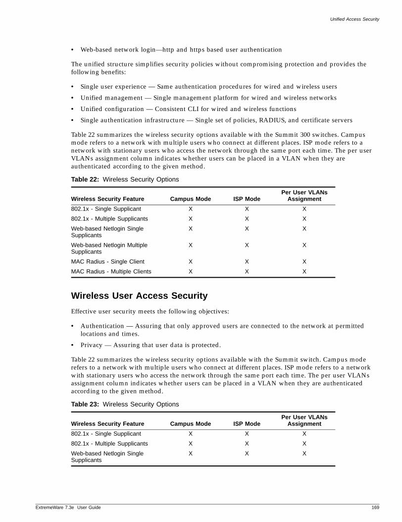
Unified Access Security
ExtremeWare 7
• Web-based network login—http and https based user authentication
The unified structure simplifies security policies without compromising protection and provides the following benefits:
• Single user experience — Same authentication procedures for wired and wireless users
• Unified management — Single management platform for wired and wireless networks
• Unified configuration — Consistent CLI for wired and wireless functions
• Single authentication infrastructure — Single set of policies, RADIUS, and certificate servers
Table 22 summarizes the wireless security options available with the Summit 300 switches. Campus mode refers to a network with multiple users who connect at different places. ISP mode refers to a network with stationary users who access the network through the same port each time. The per user VLANs assignment column indicates whether users can be placed in a VLAN when they are authenticated according to the given method.
Wireless User Access Security
Effective user security meets the following objectives:
• Authentication — Assuring that only approved users are connected to the network at permitted locations and times.
• Privacy — Assuring that user data is protected.
Table 22 summarizes the wireless security options available with the Summit switch. Campus mode refers to a network with multiple users who connect at different places. ISP mode refers to a network with stationary users who access the network through the same port each time. The per user VLANs assignment column indicates whether users can be placed in a VLAN when they are authenticated according to the given method.
Table 22: Wireless Security Options
Wireless Security Feature Campus Mode ISP ModePer User VLANs
Assignment802.1x - Single Supplicant X X X
802.1x - Multiple Supplicants X X X
Web-based Netlogin Single Supplicants
X X X
Web-based Netlogin Multiple Supplicants
X X X
MAC Radius - Single Client X X X
MAC Radius - Multiple Clients X X X
Table 23: Wireless Security Options
Wireless Security Feature Campus Mode ISP ModePer User VLANs
Assignment802.1x - Single Supplicant X X X
802.1x - Multiple Supplicants X X X
Web-based Netlogin Single Supplicants
X X X
.3e User Guide 169
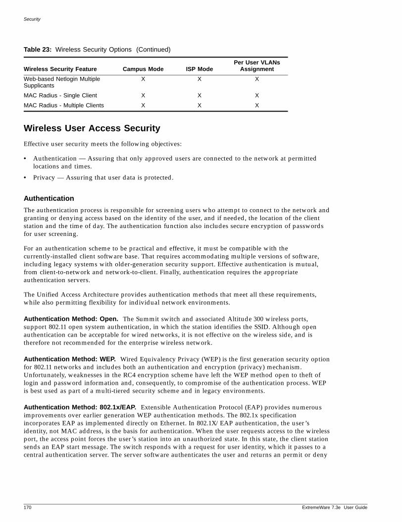
Security
Wireless User Access Security
Effective user security meets the following objectives:
• Authentication — Assuring that only approved users are connected to the network at permitted locations and times.
• Privacy — Assuring that user data is protected.
Authentication
The authentication process is responsible for screening users who attempt to connect to the network and granting or denying access based on the identity of the user, and if needed, the location of the client station and the time of day. The authentication function also includes secure encryption of passwords for user screening.
For an authentication scheme to be practical and effective, it must be compatible with the currently-installed client software base. That requires accommodating multiple versions of software, including legacy systems with older-generation security support. Effective authentication is mutual, from client-to-network and network-to-client. Finally, authentication requires the appropriate authentication servers.
The Unified Access Architecture provides authentication methods that meet all these requirements, while also permitting flexibility for individual network environments.
Authentication Method: Open. The Summit switch and associated Altitude 300 wireless ports, support 802.11 open system authentication, in which the station identifies the SSID. Although open authentication can be acceptable for wired networks, it is not effective on the wireless side, and is therefore not recommended for the enterprise wireless network.
Authentication Method: WEP. Wired Equivalency Privacy (WEP) is the first generation security option for 802.11 networks and includes both an authentication and encryption (privacy) mechanism. Unfortunately, weaknesses in the RC4 encryption scheme have left the WEP method open to theft of login and password information and, consequently, to compromise of the authentication process. WEP is best used as part of a multi-tiered security scheme and in legacy environments.
Authentication Method: 802.1x/EAP. Extensible Authentication Protocol (EAP) provides numerous improvements over earlier generation WEP authentication methods. The 802.1x specification incorporates EAP as implemented directly on Ethernet. In 802.1X/EAP authentication, the user’s identity, not MAC address, is the basis for authentication. When the user requests access to the wireless port, the access point forces the user’s station into an unauthorized state. In this state, the client station sends an EAP start message. The switch responds with a request for user identity, which it passes to a central authentication server. The server software authenticates the user and returns an permit or deny
Web-based Netlogin Multiple Supplicants
X X X
MAC Radius - Single Client X X X
MAC Radius - Multiple Clients X X X
Table 23: Wireless Security Options (Continued)
Wireless Security Feature Campus Mode ISP ModePer User VLANs
Assignment
170 ExtremeWare 7.3e User Guide
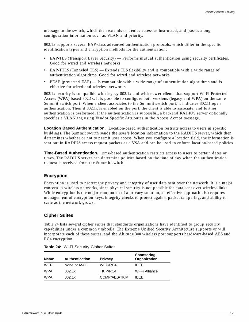
Unified Access Security
ExtremeWare 7
message to the switch, which then extends or denies access as instructed, and passes along configuration information such as VLAN and priority.
802.1x supports several EAP-class advanced authentication protocols, which differ in the specific identification types and encryption methods for the authentication:
• EAP-TLS (Transport Layer Security) — Performs mutual authentication using security certificates. Good for wired and wireless networks
• EAP-TTLS (Tunneled TLS) — Extends TLS flexibility and is compatible with a wide range of authentication algorithms. Good for wired and wireless networks
• PEAP (protected EAP) — Is compatible with a wide range of authentication algorithms and is effective for wired and wireless networks
802.1x security is compatible with legacy 802.1x and with newer clients that support Wi-Fi Protected Access (WPA) based 802.1x. It is possible to configure both versions (legacy and WPA) on the same Summit switch port. When a client associates to the Summit switch port, it indicates 802.11 open authentication. Then if 802.1x is enabled on the port, the client is able to associate, and further authentication is performed. If the authentication is successful, a backend RADIUS server optionally specifies a VLAN tag using Vendor Specific Attributes in the Access Accept message.
Location Based Authentication. Location-based authentication restricts access to users in specific buildings. The Summit switch sends the user’s location information to the RADIUS server, which then determines whether or not to permit user access. When you configure a location field, the information is sent out in RADIUS access request packets as a VSA and can be used to enforce location-based policies.
Time-Based Authentication. Time-based authentication restricts access to users to certain dates or times. The RADIUS server can determine policies based on the time of day when the authentication request is received from the Summit switch.
Encryption
Encryption is used to protect the privacy and integrity of user data sent over the network. It is a major concern in wireless networks, since physical security is not possible for data sent over wireless links. While encryption is the major component of a privacy solution, an effective approach also requires management of encryption keys, integrity checks to protect against packet tampering, and ability to scale as the network grows.
Cipher Suites
Table 24 lists several cipher suites that standards organizations have identified to group security capabilities under a common umbrella. The Extreme Unified Security Architecture supports or will incorporate each of these suites, and the Altitude 300 wireless port supports hardware-based AES and RC4 encryption.
Table 24: Wi-Fi Security Cipher Suites
Name Authentication PrivacySponsoring Organization
WEP None or MAC WEP/RC4 IEEE
WPA 802.1x TKIP/RC4 Wi-Fi Alliance
WPA 802.1x CCMP/AES/TKIP IEEE
.3e User Guide 171
Security
WPA-Only Support. To support WPA clients, the Summit switch port sets the privacy bit in the beacon frames it advertises. The switch also advertises the set of supported unicast and multicast cipher suites and the configured and supported authentication modes as part of the association request.
WPA support is compatible with 802.1x authentication and with pre-shared keys. With pre-shared keys, key derivation and distribution are done using the EAPOL-KEY messages. All clients that indicate PSK are assigned to the default user VLAN, which is configured on the Summit switch port.
Legacy and WPA 802.1x Support. When network authentication is set to dot1x, WPA clients can use TKIP for their unicast data exchange and the specified WEP64 or WEP128 cipher for multicast traffic. Legacy 802.1x clients should use the specified WEP64 or WEP128 cipher for both their unicast and multicast cipher.
Network Security Policies for Wireless InterfacesNetwork security policy refers to a set of network rules that apply to user access. You can base the rules on a variety of factors, including user identification, time and location, and method of authentication. It is possible to design network security policies to do all of the following:
• Permit or deny network access based on location and time of day.
• Place the user into a VLAN based on identity or authentication method.
• Limit where the user is permitted to go on the network based on identity or authentication method.
Policy Design
When designing a security policy for your network, keep the following objectives in mind:
• Make each wired and wireless client as secure as possible.
• Protect company resources.
• Make the network infrastructure as secure as possible.
• Be able to track and identify wired and wireless rogues.
To achieve these objectives, it is necessary to work within the constraints of your environment:
• Technology of all the clients
— 802.11 radio technology (b, a, g, a/b, a/g)
— Operating system (W2K, XP, Pocket PC, ….)
— Client readiness for 802.1x; client upgrades
• Authentication servers available or planned
— Operating System Login only (i.e. Domain Access, LDAP)
— RADIUS for Users
— PKI Infrastructure
• Nature of the user population
• Ability to divide users into meaningful groups
• Network resources required by users
• Desired access restrictions based on resources, locations, times, and security level
• Acceptable level of network management and user training
172 ExtremeWare 7.3e User Guide
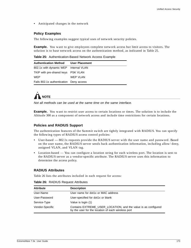
Unified Access Security
ExtremeWare 7
• Anticipated changes in the network
Policy Examples
The following examples suggest typical uses of network security policies.
Example. You want to give employees complete network access but limit access to visitors. The solution is to base network access on the authentication method, as indicated in Table 25.
NOTE
Not all methods can be used at the same time on the same interface.
Example. You want to restrict user access to certain locations or times. The solution is to include the Altitude 300 as a component of network access and include time restrictions for certain locations.
Policies and RADIUS Support
The authentication features of the Summit switch are tightly integrated with RADIUS. You can specify the following types of RADIUS access control policies:
• User-based — 802.1x requests provide the RADIUS server with the user name and password. Based on the user name, the RADIUS server sends back authentication information, including allow/deny, assigned VLAN, and VLAN tag.
• Location-based — You can configure a location string for each wireless port. The location is sent to the RADIUS server as a vendor-specific attribute. The RADIUS server uses this information to determine the access policy.
RADIUS Attributes
Table 26 lists the attributes included in each request for access:
Table 25: Authentication-Based Network Access Example
Authentication Method User Placement
802.1x with dynamic WEP Internal VLAN
TKIP with pre-shared keys PSK VLAN
WEP WEP VLAN
Fails 802.1x authentication Deny access
Table 26: RADIUS Request Attributes
Attribute Description
User-Name User name for dot1x or MAC address
User-Password User-specified for dot1x or blank
Service-Type Value is login (1)
Vendor-Specific Contains EXTREME_USER_LOCATION, and the value is as configured by the user for the location of each wireless port
.3e User Guide 173
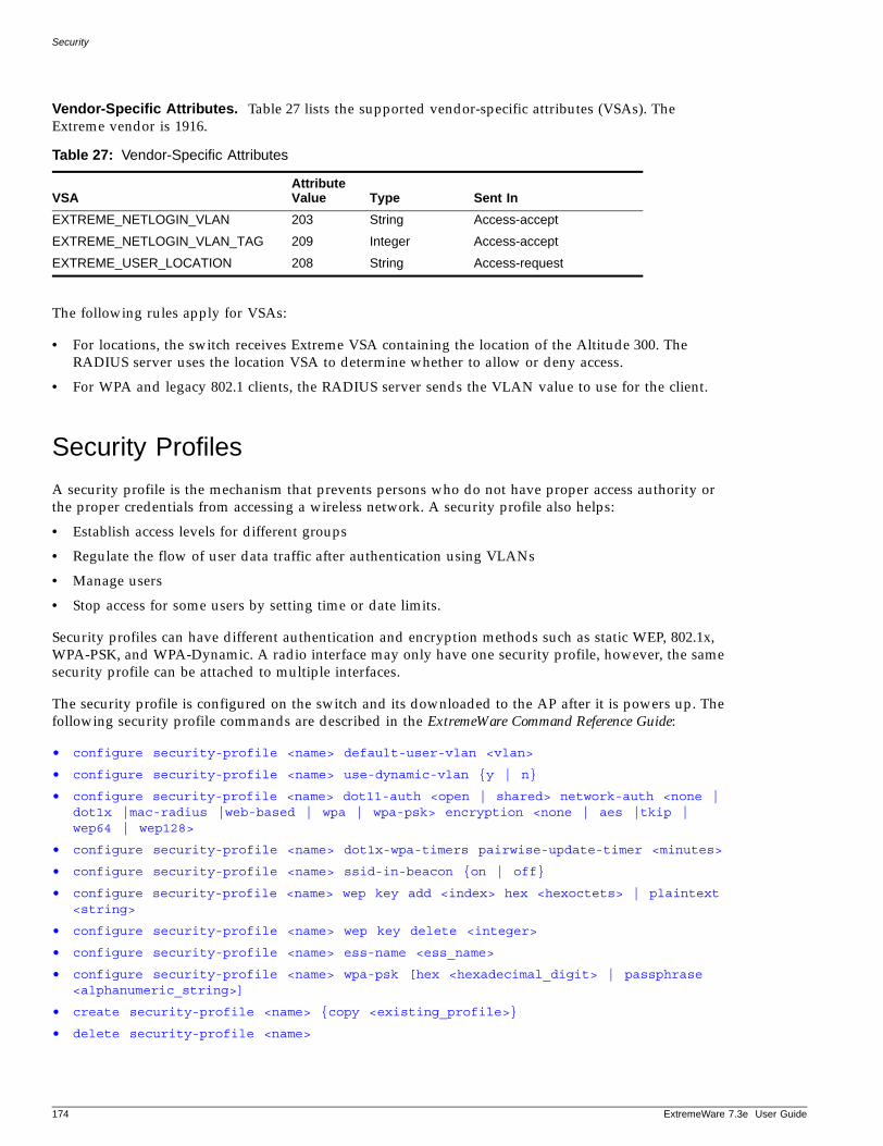
Security
Vendor-Specific Attributes. Table 27 lists the supported vendor-specific attributes (VSAs). The Extreme vendor is 1916.
The following rules apply for VSAs:
• For locations, the switch receives Extreme VSA containing the location of the Altitude 300. The RADIUS server uses the location VSA to determine whether to allow or deny access.
• For WPA and legacy 802.1 clients, the RADIUS server sends the VLAN value to use for the client.
Security Profiles
A security profile is the mechanism that prevents persons who do not have proper access authority or the proper credentials from accessing a wireless network. A security profile also helps:
• Establish access levels for different groups
• Regulate the flow of user data traffic after authentication using VLANs
• Manage users
• Stop access for some users by setting time or date limits.
Security profiles can have different authentication and encryption methods such as static WEP, 802.1x, WPA-PSK, and WPA-Dynamic. A radio interface may only have one security profile, however, the same security profile can be attached to multiple interfaces.
The security profile is configured on the switch and its downloaded to the AP after it is powers up. The following security profile commands are described in the ExtremeWare Command Reference Guide:
• configure security-profile <name> default-user-vlan <vlan>
• configure security-profile <name> use-dynamic-vlan {y | n}
• configure security-profile <name> dot11-auth <open | shared> network-auth <none | dot1x |mac-radius |web-based | wpa | wpa-psk> encryption <none | aes |tkip | wep64 | wep128>
• configure security-profile <name> dot1x-wpa-timers pairwise-update-timer <minutes>
• configure security-profile <name> ssid-in-beacon {on | off}
• configure security-profile <name> wep key add <index> hex <hexoctets> | plaintext <string>
• configure security-profile <name> wep key delete <integer>
• configure security-profile <name> ess-name <ess_name>
• configure security-profile <name> wpa-psk [hex <hexadecimal_digit> | passphrase <alphanumeric_string>]
• create security-profile <name> {copy <existing_profile>}
• delete security-profile <name>
Table 27: Vendor-Specific Attributes
VSAAttribute Value Type Sent In
EXTREME_NETLOGIN_VLAN 203 String Access-accept
EXTREME_NETLOGIN_VLAN_TAG 209 Integer Access-accept
EXTREME_USER_LOCATION 208 String Access-request
174 ExtremeWare 7.3e User Guide
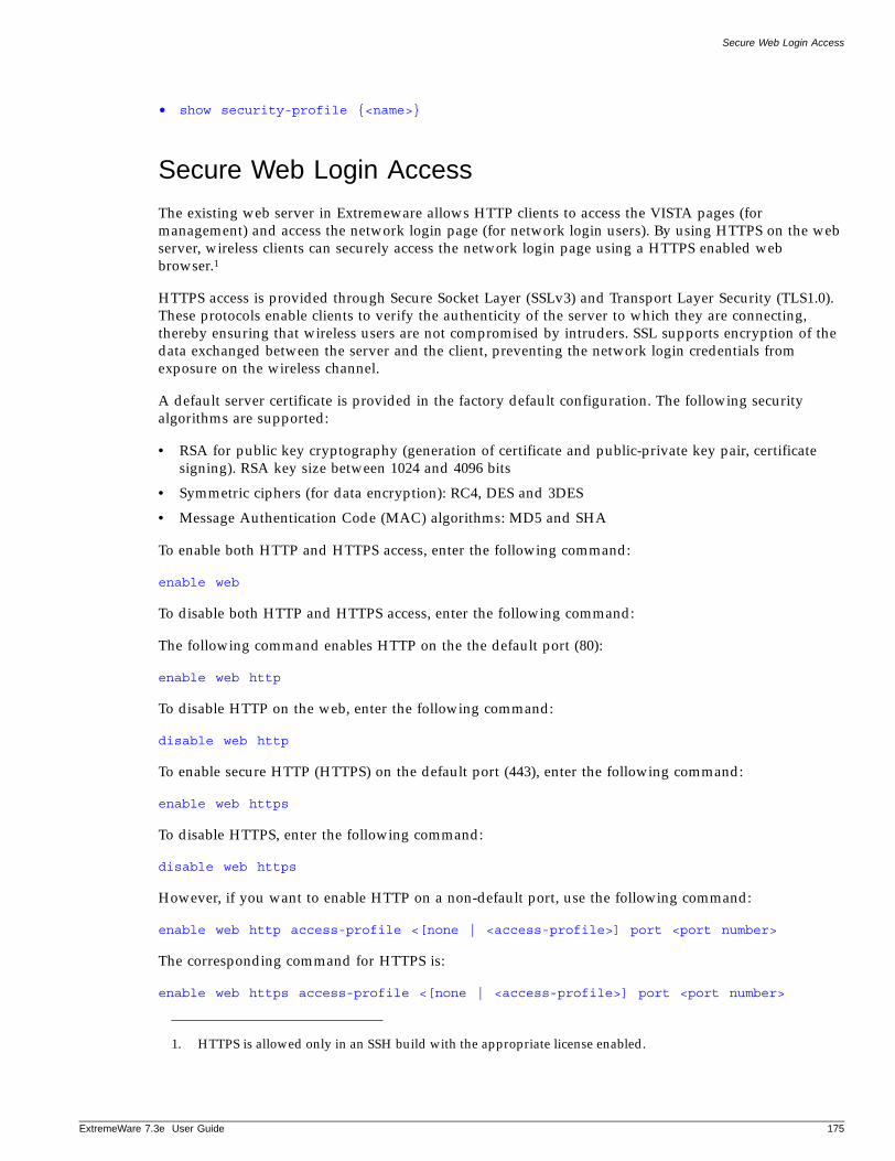
Secure Web Login Access
ExtremeWare 7
• show security-profile {<name>}
Secure Web Login Access
The existing web server in Extremeware allows HTTP clients to access the VISTA pages (for management) and access the network login page (for network login users). By using HTTPS on the web server, wireless clients can securely access the network login page using a HTTPS enabled web browser.1
HTTPS access is provided through Secure Socket Layer (SSLv3) and Transport Layer Security (TLS1.0). These protocols enable clients to verify the authenticity of the server to which they are connecting, thereby ensuring that wireless users are not compromised by intruders. SSL supports encryption of the data exchanged between the server and the client, preventing the network login credentials from exposure on the wireless channel.
A default server certificate is provided in the factory default configuration. The following security algorithms are supported:
• RSA for public key cryptography (generation of certificate and public-private key pair, certificate signing). RSA key size between 1024 and 4096 bits
• Symmetric ciphers (for data encryption): RC4, DES and 3DES
• Message Authentication Code (MAC) algorithms: MD5 and SHA
To enable both HTTP and HTTPS access, enter the following command:
enable web
To disable both HTTP and HTTPS access, enter the following command:
The following command enables HTTP on the the default port (80):
enable web http
To disable HTTP on the web, enter the following command:
disable web http
To enable secure HTTP (HTTPS) on the default port (443), enter the following command:
enable web https
To disable HTTPS, enter the following command:
disable web https
However, if you want to enable HTTP on a non-default port, use the following command:
enable web http access-profile <[none | <access-profile>] port <port number>
The corresponding command for HTTPS is:
enable web https access-profile <[none | <access-profile>] port <port number>
1. HTTPS is allowed only in an SSH build with the appropriate license enabled.
.3e User Guide 175
Security
To display session information, including HTTPS sessions, enter the following command:
show session
You can also use the following command to display whether the switch has a valid private and public key pair and the state of HTTPS access:
show management
Creating Certificates and Private KeysA default certificate and private key are stored in the NVRAM factory default settings. The certificate generated is in X509v3 format. The certificate generated is in PEM format.
To create a self-signed certificate and private key that can be saved in NVRAM, enter the following command:
configure ssl certificate prikeylen <length> country <code> organization <org_name> common-name <name>
Be sure to specify the following:
• Country code (exactly 2 characters),
• Organization name (max size of 64 characters) and
• Common Name (max size of 64 chars) in the command.
Any existing certificate and private key is overwritten.
Most web browsers check whether the common-name field in the received server certificate is the same as the URL used to reach the site, otherwise they give a warning.
The size of the certificate generated depends on the RSA Key length (privkeylen) and the length of the other parameters (country, organization name etc.) supplied by the user. If the RSA key length is 1024, then the certificate size is ~ 1kb and the private key length is ~1kb. For RSA Key length of 4096, the certificate length is ~2kb and the private key length is ~3kb
Downloading a Certificate Key from a TFTP Server
You can download a certificate key from friles stored in a TFTP server. If the operation is successful, any existing certificate is overwritten. After a successful download, the software attempts to match the public key in the certificate matches the private key stored. If the private and public keys do not match, a warning message is displayed (“Warning: The Priate Key does not match with the Public Key in the certificate.”). This warning acts as a reminder to the user to also download the private key.
The certificate and private key should be in PEM format and generated using RSA as the cryptography alorithm.
Use the following command to download a certificate key from files stored in a TFTP server:
download ssl <ip address> certificate <cert file>
To see whether the private key matches with the public key stored in the certificate, use the following command:
show ssl
176 ExtremeWare 7.3e User Guide
Secure Web Login Access
ExtremeWare 7
This command also displays:
• HTTPS port configured. This is the port on which the clients will connect.
• Length of RSA key (number of bits used to generate the private key)
• Basic information about the stored certificate
To also see the full certificate, use the detail keyword:
show ssl {detail}
Downloading a Private Key from a TFTP Server
To download a private key from files stores in a TFTP server, use the following command:
download ssl <ip address> privkey <key file>
When this command is executed, if the private key is encrypted, the user is prompted to enter the passphrase that was used to encrypt the private key when the private key was generated. Only DES and 3DES encryption mechanisms are supported for private key encryption. If the operation is successful the existing private key is overwritten.
After the download is successful, a check is performed to find out whether the private key downloaded matches with the public key stored in the certificate. If they do not match, a warning message is displayed (“Warning: The Private Key does not match with the Public Key in the certificate.”). This warning acts as a reminder to the user to download the corresponding certificate.
The certificate and private key file should be in PEM format and generated using RSA as the cryptography algorithm.
Configuring Pre-generated Certificates and Keys
Use the following command to get the pre-generated certificate from the user:
configure ssl certificate pregenerated
This command is also used when downloading/ uploading the configuration. The certificate information stored in the uploaded configuration file should not be modified, because it is signed using the issuer’s private key.
The certificate and private key file should be in PEM format and generated using RSA as the cryptography algorithm.
To get a pre-generated private key from the user, user the following command:
configure ssl privkey pregenerated
This command will also be used when downloading/uploading the configuration. The private key will be stored in the uploaded configuration file in an encrypted format using a hard coded passphrase. Hence the private key information in the configuration file should not be modified.
The certificate and private key file should be in PEM format and generated using RSA as the cryptography algorithm.
.3e User Guide 177
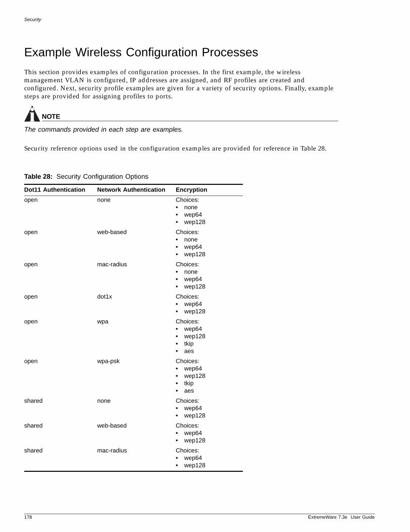
Security
Example Wireless Configuration Processes
This section provides examples of configuration processes. In the first example, the wireless management VLAN is configured, IP addresses are assigned, and RF profiles are created and configured. Next, security profile examples are given for a variety of security options. Finally, example steps are provided for assigning profiles to ports.
NOTE
The commands provided in each step are examples.
Security reference options used in the configuration examples are provided for reference in Table 28.
Table 28: Security Configuration Options
Dot11 Authentication Network Authentication Encryptionopen none Choices:
• none• wep64• wep128
open web-based Choices:• none• wep64• wep128
open mac-radius Choices:• none• wep64• wep128
open dot1x Choices:• wep64• wep128
open wpa Choices:• wep64• wep128• tkip• aes
open wpa-psk Choices:• wep64• wep128• tkip• aes
shared none Choices:• wep64• wep128
shared web-based Choices:• wep64• wep128
shared mac-radius Choices:• wep64• wep128
178 ExtremeWare 7.3e User Guide
Example Wireless Configuration Processes
ExtremeWare 7
Wireless Management Configuration ExampleRefer to the following example when configuring VLAN, IP addresses, and RF profiles.
NOTE
Any addition, deletion or movement of wireless ports from vlan to vlan must be preceded by disabling the wireless port(s).
Configure the VLAN, Wireless Port IP Addresses and RF-profiles:
1 Create a vlan to be use as the wireless management VLAN.
create vlan manage-wireless
2 Remove the wireless port from the default VLAN.
config vlan default delete ports 1:5
NOTE
NOTE: Following warning message may be displayed as a result of the above command. This will not prevent the port from being deleted from the default vlan:
WARNING: Security profile applied to port 1:5 refers to the VLAN Default. Removing the port from the VLAN will cause incorrect behavior
3 Add the wireless port to the management VLAN as an untagged port.
config vlan manage-wireless add ports 1:5 untagged.
4 Assign an IP address to the VLAN.
config vlan manage-wireless ipaddress 10.211.37.1/24
5 Configure this VLAN as the management VLAN.
config wireless management-vlan manage-wireless
NOTE
Following warning message may occur as a result of the above command. This will not prevent the command from executing.
Warning: Changing the management VLAN can cause access points to loose contact with LAC.
6 Assign a management IP address for each wireless port (port 1:5 in the example). Be sure that the address is in the same network as the wireless management-vlan.
config wireless port 1:5 ip-address 10.211.37.105
7 Create an RF profile for the A interfaces by copying from the default profile.
create rf-profile RF_A copy DEFAULT_A
8 Create an RF profile for the G interfaces by copying from the default profile.
create rf-profile RF_G copy DEFAULT_G
.3e User Guide 179
Security
Security Configuration ExamplesRefer to the examples in this section when configuring any of the available wireless security options for the Summit 300-48 switch. The examples encompass most typical security scenarios.
NOTE
Because of the requirement to add potential wireless ports to the wireless management-vlan as untagged ports, adding a wireless port to a data/client vlan requires that the port be added as a tagged port.
NOTE
The “default-user-vlan” parameter is NOT used as a destination vlan in the case of an authentication failure. For this parameter, if the client authentication succeeds, the client will be placed into the VLAN indicated in the parameter or into the VLAN indicated by a Vendor Specific Attribute (VSA) VLAN-ID or VLAN Name. Any authentication failures will deny the client access to the network.
NOTE
In the following examples, the heading of each example is formatted as follows:
Dot11 Authentication – Network Authentication – Encryption/Multicast Cipher
Open - None - None
1 Create a security profile (open-auth) by copying from the default unsecure profile.
create security-profile open-auth copy unsecure
2 Create a VLAN (open-vlan) for the potential clients that will connect to the network using this security-profile.
create vlan open-vlan
3 Configure the tag for the VLAN
config vlan open-vlan tag 10
4 Add the wireless port to the VLAN.
config vlan open-vlan add ports 1:5 tagged
5 Configure the Dot11 Authentication, Network Authentication and Multicast Cipher/Encryption and also assign the “default-user-vlan” parameter.
config security-profile open-auth dot11-auth open network-auth none encryption noneconfig security-profile open-auth default-user-vlan open-vlan
6 Configure the name of the ESS
config security-profile open-auth ess-name open-ess
Open - None - Wep 64
1 Create a security profile (wep-secure) by copying from the default unsecure profile.
create security-profile wep-secure copy unsecure
180 ExtremeWare 7.3e User Guide
Example Wireless Configuration Processes
ExtremeWare 7
2 Create a VLAN (wep-vlan) for the potential clients that will connect to the network using this security-profile.
create vlan wep-vlan
3 Configure the tag for the VLAN
config vlan wep-vlan tag 10
4 Add the wireless port to the VLAN.
config vlan wep-vlan add ports 1:5 tagged
5 Configure the Dot11 Authentication, Network Authentication and Multicast Cipher/Encryption and also assign the “default-user-vlan” parameter.
config security-profile wep-secure dot11-auth open network-auth none encryption wep64config security-profile wep-secure default-user-vlan wep-vlan
NOTE
If you attach this security-profile to a port before configure at least 1 WEP key, an error message will be generated:
Warning: At least one WEP key has to be specified before applying this security profile to the interface
6 Configure the security profile with WEP key to match the encryption length indicated in Step 5.
config security-profile wep-secure wep key add 0 hex abcdefaaaa
NOTE
If you enter the wrong number of characters for the code, a message similar to the following appears.
Invalid number of bytes in key. Expected <xx> bytes, got <yy> bytes.
7 Configure the security profile to use the 0 key you just defined as the default encryption key.
config security-profile wep-secure wep default-key-index 0
8 Configure the name of the ESS
config security-profile wep-secure ess-name open-wep64-ess
Open - None - WEP 128
1 Create a security profile (wep-secure) by copying from the default unsecure profile.
create security-profile wep-secure copy unsecure
2 Create a VLAN (wep-vlan) for the potential clients that will connect to the network using this security-profile.
create vlan wep-vlan
3 Configure the tag for the VLAN
config vlan wep-vlan tag 10
4 Add the wireless port to the VLAN.
config vlan wep-vlan add ports 1:5 tagged
.3e User Guide 181
Security
5 Configure the Dot11 Authentication, Network Authentication and Multicast Cipher/Encryption and also assign the “default-user-vlan” parameter.
config security-profile wep-secure dot11-auth open network-auth none encryption wep128config security-profile wep-secure default-user-vlan wep-vlan
NOTE
If you attach this security-profile to a port before configure at least 1 WEP key, an error message will be generated:
Warning: At least one WEP key has to be specified before applying this security profile to the interface
6 Configure the security profile with WEP key to match the encryption length indicated in Step 5.
config security-profile wep-secure wep key add 0 hex aaaaaaaaaaaaaccccccccccccc
NOTE
If you enter the wrong number of characters for the code, a message similar to the following appears.
Invalid number of bytes in key. Expected <xx> bytes, got <yy> bytes.
7 Configure the security profile to use the 0 key you just defined as the default encryption key.
config security-profile wep-secure wep default-key-index 0
8 Configure the name of the ESS
config security-profile wep-secure ess-name open-wep128-ess
Open - Web Based Network Login - None
1 Create a security profile (web-based-open) by copying from the default unsecure profile.
create security-profile web-based-open copy unsecure
2 Create a VLAN (web-vlan) for the potential clients that will connect to the network using this security-profile.
create vlan web-vlan
3 Configure the tag for the VLAN
config vlan web-vlan tag 10
4 Add the wireless port to the VLAN.
config vlan web-vlan add ports 1:5 tagged
5 Configure the Dot11 Authentication, Network Authentication and Multicast Cipher/Encryption and also assign the “default-user-vlan” parameter.
config security-profile web-based-open dot11-auth open network-auth web-based encryption noneconfig security-profile web-based-open default-user-vlan web-vlan
6 Configure the name of the ESS
config security-profile web-based-open ess-name open-web-ess
182 ExtremeWare 7.3e User Guide
Example Wireless Configuration Processes
ExtremeWare 7
Open - Web Based Network Login - WEP 64
1 Create a security profile (web-based-64) by copying from the default unsecure profile.
create security-profile web-based-64 copy unsecure
2 Create a VLAN (web-vlan) for the potential clients that will connect to the network using this security-profile.
create vlan web-vlan
3 Configure the tag for the VLAN
config vlan web-vlan tag 10
4 Add the wireless port to the VLAN.
config vlan web-vlan add ports 1:5 tagged
5 Configure the Dot11 Authentication, Network Authentication and Multicast Cipher/Encryption and also assign the “default-user-vlan” parameter.
config security-profile web-based-64 dot11-auth open network-auth web-based encryption wep64config security-profile web-based-64 default-user-vlan web-vlan
6 Configure the security profile with a WEP key of encryption length 64.
config Security-profile web-based-64 wep key add 0 hex abcdefaaaa
NOTE
If you enter the wrong number of characters for the code, a message similar to the following appears.
Invalid number of bytes in key. Expected <xx> bytes, got <yy> bytes.
7 Configure the security profile to use the 0 key you just defined as the default encryption key.
config security-profile web-based-64 wep default-key-index 0
8 Configure the name of the ESS
config security-profile web-based-64 ess-name web-based-64-ess
Open - Web Based Network Login - WEP 128
1 Create a security profile (web-based-128) by copying from the default unsecure profile.
create security-profile web-based-128 copy unsecure
2 Create a VLAN (web-vlan) for the potential clients that will connect to the network using this security-profile.
create vlan web-vlan
3 Configure the tag for the VLAN
config vlan web-vlan tag 10
4 Add the wireless port to the VLAN.
config vlan web-vlan add ports 1:5 tagged
5 Configure the Dot11 Authentication, Network Authentication and Multicast Cipher/Encryption and also assign the “default-user-vlan” parameter.
config security-profile web-based-128 dot11-auth open network-auth web-based encryption wep128
.3e User Guide 183
Security
config security-profile web-based-128 default-user-vlan web-vlan
6 Configure the security profile with a WEP key of encryption length 128
config security-profile web-based-128 wep key add 0 hex abcdefaaaaaaaaaaaaaaaaaaaa
NOTE
If you enter the wrong number of characters for the code, a message similar to the following appears.
Invalid number of bytes in key. Expected <xx> bytes, got <yy> bytes.
7 Configure the security profile to use the 0 key you just defined as the default encryption key.
config security-profile web-based-128 wep default-key-index 0
8 Configure the name of the ESS
config security-profile web-based-128 ess-name web-based-128-ess
Open - MAC Radius - None
1 Create a security profile (mac-radius-open) by copying from the default unsecure profile.
create security-profile mac-radius-open copy unsecure
2 Create a VLAN (mac-radius-vlan) for the potential clients that will connect to the network using this security-profile.
create vlan mac-radius-vlan
3 Configure the tag for the VLAN
config vlan mac-radius-vlan tag 10
4 Add the wireless port to the VLAN.
config vlan mac-radius-vlan add ports 1:5 tagged
5 Configure the Dot11 Authentication, Network Authentication and Multicast Cipher/Encryption and also assign the “default-user-vlan” parameter.
config security-profile mac-radius-open dot11-auth open network-auth mac-radius encryption noneconfig security-profile mac-radius-open default-user-vlan mac-radius-vlan
6 Configure the name of the ESS
config security-profile mac-radius-open ess-name mac-radius-open-ess
Open - MAC Radius - WEP 64
1 Create a security profile (mac-radius-64) by copying from the default unsecure profile.
create security-profile mac-radius-64 copy unsecure
2 Create a VLAN (mac-radius-vlan) for the potential clients that will connect to the network using this security-profile.
create vlan mac-radius-vlan
3 Configure the tag for the VLAN
config vlan mac-radius-vlan tag 10
4 Add the wireless port to the VLAN.
184 ExtremeWare 7.3e User Guide
Example Wireless Configuration Processes
ExtremeWare 7
config vlan mac-radius-vlan add ports 1:5 tagged
5 Configure the Dot11 Authentication, Network Authentication and Multicast Cipher/Encryption and also assign the “default-user-vlan” parameter.
config security-profile mac-radius-64 dot11-auth open network-auth mac-radius encryption wep64config security-profile mac-radius-64 default-user-vlan mac-radius-vlan
6 Configure the security profile with a WEP key of encryption length 64.
config security-profile mac-radius-64 wep key add 0 hex abcdefaaaa
NOTE
If you enter the wrong number of characters for the code, a message similar to the following appears.
Invalid number of bytes in key. Expected <xx> bytes, got <yy> bytes.
7 Configure the security profile to use the 0 key you just defined as the default encryption key.
config security-profile mac-radius-64 wep default-key-index 0
8 Configure the name of the ESS
config security-profile mac-radius-64 ess-name mac-radius-64-ess
Open - MAC Radius - WEP 128
1 Create a security profile (mac-radius-128) by copying from the default unsecure profile.
create security-profile mac-radius-128 copy unsecure
2 Create a VLAN (mac-radius-vlan) for the potential clients that will connect to the network using this security-profile.
create vlan mac-radius-vlan
3 Configure the tag for the VLAN
config vlan mac-radius-vlan tag 10
Add the wireless port to the VLAN.
config vlan mac-radius-vlan add ports 1:5 tagged
4 Configure the Dot11 Authentication, Network Authentication and Multicast Cipher/Encryption and also assign the “default-user-vlan” parameter.
config security-profile mac-radius-128 dot11-auth open network-auth mac-radius encryption wep128config security-profile mac-radius-128 default-user-vlan mac-radius-vlan
5 Configure the security profile with a WEP key of encryption length 128
config security-profile mac-radius-128 wep key add 0 hex abcdefaaaaaaaaaaaaaaaaaaaa
NOTE
If you enter the wrong number of characters for the code, a message similar to the following appears.
Invalid number of bytes in key. Expected <xx> bytes, got <yy> bytes.
6 Configure the security profile to use the 0 key you just defined as the default encryption key.
.3e User Guide 185
Security
config security-profile mac-radius-128 wep default-key-index 0
7 Configure the name of the ESS
config security-profile mac-radius-128 ess-name mac-radius-128-ess
Open - Dot1x - WEP 64
1 Create a security profile (open-dot1x-64) by copying from the default unsecure profile.
create security-profile open-dot1x-64 copy unsecure
2 Create a VLAN (dot1x-vlan) for the potential clients that will connect to the network using this security-profile.
create vlan dot1x-vlan
3 Configure the tag for the VLAN
config vlan dot1x-vlan tag 10
4 Add the wireless port to the VLAN.
config vlan dot1x-vlan add ports 1:5 tagged
5 Configure the Dot11 Authentication, Network Authentication and Multicast Cipher/Encryption and also assign the “default-user-vlan” parameter.
config security-profile open-dot1x-64 dot11-auth open network-auth dot1x encryption wep64config security-profile open-dot1x-64 default-user-vlan dot1x-vlan
6 Configure the name of the ESS
config security-profile open-dot1x-64 ess-name open-dot1x-64-ess
Open - Dot1x - WEP 128
1 Create a security profile (open-dot1x-128) by copying from the default unsecure profile.
create security-profile open-dot1x-128 copy unsecure
2 Create a VLAN (dot1x-vlan) for the potential clients that will connect to the network using this security-profile.
create vlan dot1x-vlan
3 Configure the tag for the VLAN
config vlan dot1x-vlan tag 10
4 Add the wireless port to the VLAN.
config vlan dot1x-vlan add ports 1:5 tagged
5 Configure the Dot11 Authentication, Network Authentication and Multicast Cipher/Encryption and also assign the “default-user-vlan” parameter.
config security-profile open-dot1x-128 dot11-auth open network-auth dot1x encryption wep128config security-profile open-dot1x-128 default-user-vlan dot1x-vlan
6 Configure the name of the ESS
config security-profile open-dot1x-128 ess-name open-dot1x-128-ess
186 ExtremeWare 7.3e User Guide
Example Wireless Configuration Processes
ExtremeWare 7
Open - WPA (Dynamic) - WEP 64
1 Create a security profile (open-wpa-64) by copying from the default unsecure profile.
create security-profile open-wpa-64 copy unsecure
2 Create a VLAN (wpa-vlan) for the potential clients that will connect to the network using this security-profile.
create vlan wpa-vlan
3 Configure the tag for the VLAN
config vlan wpa-vlan tag 10
4 Add the wireless port to the VLAN.
config vlan wpa-vlan add ports 1:5 tagged
5 Configure the Dot11 Authentication, Network Authentication and Multicast Cipher/Encryption and also assign the “default-user-vlan” parameter.
config security-profile open-wpa-64 dot11-auth open network-auth wpa encryption wep64config security-profile open-wpa-64 default-user-vlan wpa-vlan
6 Configure the name of the ESS
config security-profile open-wpa-64 ess-name open-wpa-64-ess
Open - WPA (Dynamic) - WEP 128
1 Create a security profile (open-wpa-128) by copying from the default unsecure profile.
create security-profile open-wpa-128 copy unsecure
2 Create a VLAN (wpa-vlan) for the potential clients that will connect to the network using this security-profile.
create vlan wpa-vlan
3 Configure the tag for the VLAN
config vlan wpa-vlan tag 10
4 Add the wireless port to the VLAN.
config vlan wpa-vlan add ports 1:5 tagged
5 Configure the Dot11 Authentication, Network Authentication and Multicast Cipher/Encryption and also assign the “default-user-vlan” parameter.
config security-profile open-wpa-128 dot11-auth open network-auth wpa encryption wep128config security-profile open-wpa-128 default-user-vlan wpa-vlan
6 Configure the name of the ESS
config security-profile open-wpa-128 ess-name open-wpa-128-ess
Open - WPA (Dynamic) - TKIP
1 Create a security profile (open-wpa-tkip) by copying from the default unsecure profile.
create security-profile open-wpa-tkip copy unsecure
2 Create a VLAN (wpa-vlan) for the potential clients that will connect to the network using this security-profile.
.3e User Guide 187
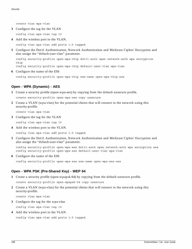
Security
create vlan wpa-vlan
3 Configure the tag for the VLAN
config vlan wpa-vlan tag 10
4 Add the wireless port to the VLAN.
config vlan wpa-vlan add ports 1:5 tagged
5 Configure the Dot11 Authentication, Network Authentication and Multicast Cipher/Encryption and also assign the “default-user-vlan” parameter.
config security-profile open-wpa-tkip dot11-auth open network-auth wpa encryption tkipconfig security-profile open-wpa-tkip default-user-vlan wpa-vlan
6 Configure the name of the ESS
config security-profile open-wpa-tkip ess-name open-wpa-tkip-ess
Open - WPA (Dynamic) - AES
1 Create a security profile (open-wpa-aes) by copying from the default unsecure profile.
create security-profile open-wpa-aes copy unsecure
2 Create a VLAN (wpa-vlan) for the potential clients that will connect to the network using this security-profile.
create vlan wpa-vlan
3 Configure the tag for the VLAN
config vlan wpa-vlan tag 10
4 Add the wireless port to the VLAN.
config vlan wpa-vlan add ports 1:5 tagged
5 Configure the Dot11 Authentication, Network Authentication and Multicast Cipher/Encryption and also assign the “default-user-vlan” parameter.
config security-profile open-wpa-aes dot11-auth open network-auth wpa encryption aesconfig security-profile open-wpa-aes default-user-vlan wpa-vlan
6 Configure the name of the ESS
config security-profile open-wpa-aes ess-name open-wpa-aes-ess
Open - WPA PSK (Pre-Shared Key) - WEP 64
1 Create a security profile (open-wpapsk-64) by copying from the default unsecure profile.
create security-profile open-wpapsk-64 copy unsecure
2 Create a VLAN (wpa-vlan) for the potential clients that will connect to the network using this security-profile.
create vlan wpa-vlan
3 Configure the tag for the wpa-vlan
config vlan wpa-vlan tag 10
4 Add the wireless port to the VLAN.
config vlan wpa-vlan add ports 1:5 tagged
188 ExtremeWare 7.3e User Guide
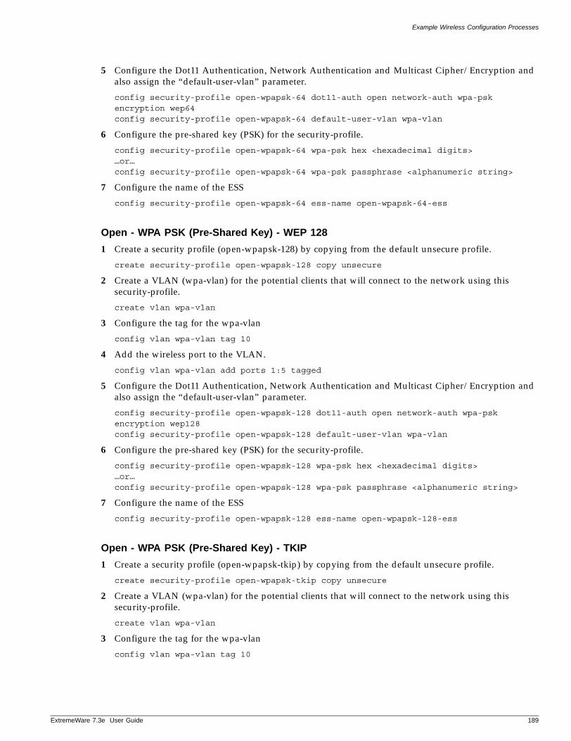
Example Wireless Configuration Processes
ExtremeWare 7
5 Configure the Dot11 Authentication, Network Authentication and Multicast Cipher/Encryption and also assign the “default-user-vlan” parameter.
config security-profile open-wpapsk-64 dot11-auth open network-auth wpa-psk encryption wep64config security-profile open-wpapsk-64 default-user-vlan wpa-vlan
6 Configure the pre-shared key (PSK) for the security-profile.
config security-profile open-wpapsk-64 wpa-psk hex <hexadecimal digits>…or…config security-profile open-wpapsk-64 wpa-psk passphrase <alphanumeric string>
7 Configure the name of the ESS
config security-profile open-wpapsk-64 ess-name open-wpapsk-64-ess
Open - WPA PSK (Pre-Shared Key) - WEP 128
1 Create a security profile (open-wpapsk-128) by copying from the default unsecure profile.
create security-profile open-wpapsk-128 copy unsecure
2 Create a VLAN (wpa-vlan) for the potential clients that will connect to the network using this security-profile.
create vlan wpa-vlan
3 Configure the tag for the wpa-vlan
config vlan wpa-vlan tag 10
4 Add the wireless port to the VLAN.
config vlan wpa-vlan add ports 1:5 tagged
5 Configure the Dot11 Authentication, Network Authentication and Multicast Cipher/Encryption and also assign the “default-user-vlan” parameter.
config security-profile open-wpapsk-128 dot11-auth open network-auth wpa-psk encryption wep128config security-profile open-wpapsk-128 default-user-vlan wpa-vlan
6 Configure the pre-shared key (PSK) for the security-profile.
config security-profile open-wpapsk-128 wpa-psk hex <hexadecimal digits>…or…config security-profile open-wpapsk-128 wpa-psk passphrase <alphanumeric string>
7 Configure the name of the ESS
config security-profile open-wpapsk-128 ess-name open-wpapsk-128-ess
Open - WPA PSK (Pre-Shared Key) - TKIP
1 Create a security profile (open-wpapsk-tkip) by copying from the default unsecure profile.
create security-profile open-wpapsk-tkip copy unsecure
2 Create a VLAN (wpa-vlan) for the potential clients that will connect to the network using this security-profile.
create vlan wpa-vlan
3 Configure the tag for the wpa-vlan
config vlan wpa-vlan tag 10
.3e User Guide 189
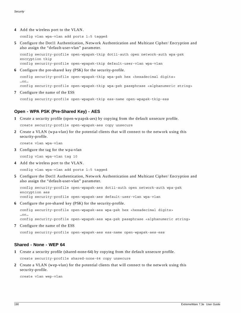
Security
4 Add the wireless port to the VLAN.
config vlan wpa-vlan add ports 1:5 tagged
5 Configure the Dot11 Authentication, Network Authentication and Multicast Cipher/Encryption and also assign the “default-user-vlan” parameter.
config security-profile open-wpapsk-tkip dot11-auth open network-auth wpa-psk encryption tkipconfig security-profile open-wpapsk-tkip default-user-vlan wpa-vlan
6 Configure the pre-shared key (PSK) for the security-profile.
config security-profile open-wpapsk-tkip wpa-psk hex <hexadecimal digits>…or…config security-profile open-wpapsk-tkip wpa-psk passphrase <alphanumeric string>
7 Configure the name of the ESS
config security-profile open-wpapsk-tkip ess-name open-wpapsk-tkip-ess
Open - WPA PSK (Pre-Shared Key) - AES
1 Create a security profile (open-wpapsk-aes) by copying from the default unsecure profile.
create security-profile open-wpapsk-aes copy unsecure
2 Create a VLAN (wpa-vlan) for the potential clients that will connect to the network using this security-profile.
create vlan wpa-vlan
3 Configure the tag for the wpa-vlan
config vlan wpa-vlan tag 10
4 Add the wireless port to the VLAN.
config vlan wpa-vlan add ports 1:5 tagged
5 Configure the Dot11 Authentication, Network Authentication and Multicast Cipher/Encryption and also assign the “default-user-vlan” parameter.
config security-profile open-wpapsk-aes dot11-auth open network-auth wpa-psk encryption aesconfig security-profile open-wpapsk-aes default-user-vlan wpa-vlan
6 Configure the pre-shared key (PSK) for the security-profile.
config security-profile open-wpapsk-aes wpa-psk hex <hexadecimal digits>…or…config security-profile open-wpapsk-aes wpa-psk passphrase <alphanumeric string>
7 Configure the name of the ESS
config security-profile open-wpapsk-aes ess-name open-wpapsk-aes-ess
Shared - None - WEP 64
1 Create a security profile (shared-none-64) by copying from the default unsecure profile.
create security-profile shared-none-64 copy unsecure
2 Create a VLAN (wep-vlan) for the potential clients that will connect to the network using this security-profile.
create vlan wep-vlan
190 ExtremeWare 7.3e User Guide
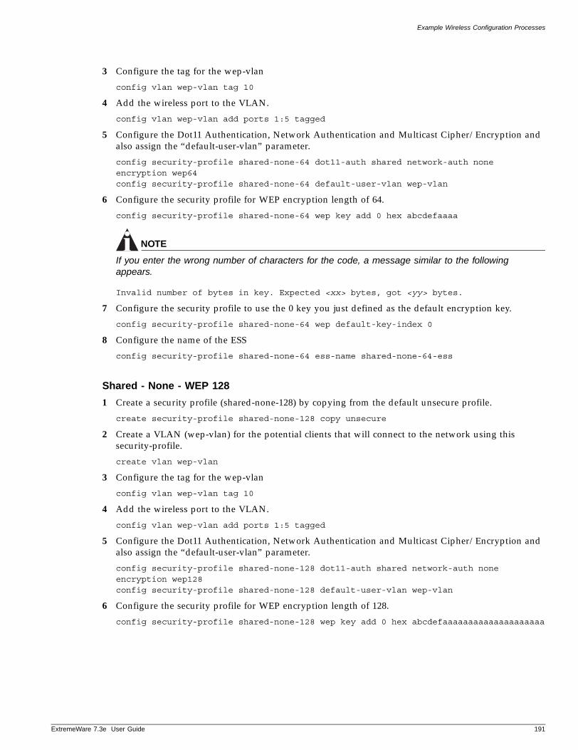
Example Wireless Configuration Processes
ExtremeWare 7
3 Configure the tag for the wep-vlan
config vlan wep-vlan tag 10
4 Add the wireless port to the VLAN.
config vlan wep-vlan add ports 1:5 tagged
5 Configure the Dot11 Authentication, Network Authentication and Multicast Cipher/Encryption and also assign the “default-user-vlan” parameter.
config security-profile shared-none-64 dot11-auth shared network-auth none encryption wep64config security-profile shared-none-64 default-user-vlan wep-vlan
6 Configure the security profile for WEP encryption length of 64.
config security-profile shared-none-64 wep key add 0 hex abcdefaaaa
NOTE
If you enter the wrong number of characters for the code, a message similar to the following appears.
Invalid number of bytes in key. Expected <xx> bytes, got <yy> bytes.
7 Configure the security profile to use the 0 key you just defined as the default encryption key.
config security-profile shared-none-64 wep default-key-index 0
8 Configure the name of the ESS
config security-profile shared-none-64 ess-name shared-none-64-ess
Shared - None - WEP 128
1 Create a security profile (shared-none-128) by copying from the default unsecure profile.
create security-profile shared-none-128 copy unsecure
2 Create a VLAN (wep-vlan) for the potential clients that will connect to the network using this security-profile.
create vlan wep-vlan
3 Configure the tag for the wep-vlan
config vlan wep-vlan tag 10
4 Add the wireless port to the VLAN.
config vlan wep-vlan add ports 1:5 tagged
5 Configure the Dot11 Authentication, Network Authentication and Multicast Cipher/Encryption and also assign the “default-user-vlan” parameter.
config security-profile shared-none-128 dot11-auth shared network-auth none encryption wep128config security-profile shared-none-128 default-user-vlan wep-vlan
6 Configure the security profile for WEP encryption length of 128.
config security-profile shared-none-128 wep key add 0 hex abcdefaaaaaaaaaaaaaaaaaaaa
.3e User Guide 191
Security
NOTE
If you enter the wrong number of characters for the code, a message similar to the following appears.
Invalid number of bytes in key. Expected <xx> bytes, got <yy> bytes.
7 Configure the security profile to use the 0 key you just defined as the default encryption key.
config security-profile shared-none-128 wep default-key-index 0
8 Configure the name of the ESS
config security-profile shared-none-128 ess-name shared-none-128-ess
Shared - Web Based Network Login - WEP 64
1 Create a security profile (shared-web-64) copying from the default unsecure profile.
create security-profile shared-web-64 copy unsecure
2 Create a VLAN (web-vlan) for the potential clients that will connect to the network using this security-profile.
create vlan web-vlan
3 Configure the tag for the web-vlan
config vlan web-vlan tag 10
4 Add the wireless port to the VLAN.
config vlan web-vlan add ports 1:5 tagged
5 Configure the Dot11 Authentication, Network Authentication and Multicast Cipher/Encryption and also assign the “default-user-vlan” parameter.
config security-profile shared-web-64 dot11-auth shared network-auth web-based encryption wep64config security-profile shared-web-64 default-user-vlan web-vlan
6 Configure the security profile for WEP encryption length of 64.
config security-profile shared-web-64 wep key add 0 hex abcdefaaaa
NOTE
If you enter the wrong number of characters for the code, a message similar to the following appears.
Invalid number of bytes in key. Expected <xx> bytes, got <yy> bytes.
7 Configure the security profile to use the 0 key you just defined as the default encryption key.
config security-profile shared-web-64 wep default-key-index 0
8 Configure the name of the ESS
config security-profile shared-web-64 ess-name shared-web-64-ess
Shared - Web Based Network Login - WEP 128
1 Create a security profile (shared-web-128) by copying from the default unsecure profile.
create security-profile shared-web-128 copy unsecure
192 ExtremeWare 7.3e User Guide
Example Wireless Configuration Processes
ExtremeWare 7
2 Create a VLAN (web-vlan) for the potential clients that will connect to the network using this security-profile.
create vlan web-vlan
3 Configure the tag for the web-vlan
config vlan web-vlan tag 10
4 Add the wireless port to the VLAN.
config vlan web-vlan add ports 1:5 tagged
5 Configure the Dot11 Authentication, Network Authentication and Multicast Cipher/Encryption and also assign the “default-user-vlan” parameter.
config security-profile shared-web-128 dot11-auth shared network-auth web-based encryption wep128config security-profile shared-web-128 default-user-vlan web-vlan
6 Configure the security profile for WEP encryption length of 128.
config security-profile shared-web-128 wep key add 0 hex abcdefaaaaaaaaaaaaaaaaaaaa
NOTE
If you enter the wrong number of characters for the code, a message similar to the following appears.
Invalid number of bytes in key. Expected <xx> bytes, got <yy> bytes.
7 Configure the security profile to use the 0 key you just defined as the default encryption key.
config security-profile shared-web-128 wep default-key-index 0
8 Configure the name of the ESS
config security-profile shared-web-128 ess-name shared-web-128-ess
Shared - MAC Radius - WEP 64
1 Create a security profile (shared-macradius-64) by copying from the default unsecure profile.
create security-profile shared-macradius-64 copy unsecure
2 Create a VLAN (mac-vlan) for the potential clients that will connect to the network using this security-profile.
create vlan mac-vlan
3 Configure the tag for the mac-vlan
config vlan mac-vlan tag 10
4 Add the wireless port to the VLAN.
config vlan mac-vlan add ports 1:5 tagged
5 Configure the Dot11 Authentication, Network Authentication and Multicast Cipher/Encryption and also assign the “default-user-vlan” parameter.
config security-profile shared-macradius-64 dot11-auth shared network-auth mac-radius encryption wep64config security-profile shared-macradius-64 default-user-vlan mac-vlan
6 Configure the security profile for WEP encryption length of 128.
config security-profile shared-macradius-64 wep key add 0 hex abcdefaaaa
.3e User Guide 193
Security
NOTE
If you enter the wrong number of characters for the code, a message similar to the following appears.
Invalid number of bytes in key. Expected <xx> bytes, got <yy> bytes.
7 Configure the security profile to use the 0 key you just defined as the default encryption key.
config security-profile shared-macradius-64 wep default-key-index 0
8 Configure the name of the ESS
config security-profile shared-marcradius-64 ess-name shared-macradius-64-ess
Shared - MAC Radius - WEP 128
1 Create a security profile (shared-macradius-128) by copying from the default unsecure profile.
create security-profile shared-macradius-128 copy unsecure
2 Create a VLAN (mac-vlan) for the potential clients that will connect to the network using this security-profile.
create vlan mac-vlan
3 Configure the tag for the mac-vlan
config vlan mac-vlan tag 10
4 Add the wireless port to the VLAN.
config vlan mac-vlan add ports 1:5 tagged
5 Configure the Dot11 Authentication, Network Authentication and Multicast Cipher/Encryption and also assign the “default-user-vlan” parameter.
config security-profile shared-macradius-128 dot11-auth shared network-auth mac-radius encryption wep128config security-profile shared-macradius-128 default-user-vlan mac-vlan
6 Configure the security profile for WEP encryption length of 128.
config security-profile shared-macradius-128 wep key add 0 hex abcdefaaaaaaaaaaaaaaaaaaaa
NOTE
If you enter the wrong number of characters for the code, a message similar to the following appears.
Invalid number of bytes in key. Expected <xx> bytes, got <yy> bytes.
7 Configure the security profile to use the 0 key you just defined as the default encryption key.
config security-profile shared-macradius-128 wep default-key-index 0
8 Configure the name of the ESS
config security-profile shared-macradius-128 ess-name shared-macradius-128-ess
Profile Assignment ExampleRefer to the following example when assigning and RF profile or security profile to a wireless interface.
194 ExtremeWare 7.3e User Guide

Switch Protection
ExtremeWare 7
Assign Profiles to Wireless Interfaces:
1 Configure interface 1 on port 1:5 to use the RF profile RF_A.
config wireless ports 1:5 interface 1 rf-profile RF_A
2 Configure interface 2 on port 1:5 to use the RF profile RF_G.
config wireless ports 1:5 interface 2 rf-profile RF_G
3 Configure interfaces 1 and 2 on port 1:5 to use the wep-secure security profile or the dotx1x-secure security profile.
config wireless ports 1:5 interface 1 security-profile wep-secureconfig wireless ports 1:5 interface 2 security-profile wep-secureORconfig wireless port 1:5 interface 1 security-profile dot1x-secureconfig wireless port 1:5 interface 2 security-profile dot1x-secure
4 Configure the channel on wireless port interface 1 and/or 2. Specifying “0” means that the channel will be “auto-selected”. Using a channel assignment of “0” will usually result in the selection of a channel with the least interference for that radio mode. Available non-auto select channels will vary depending upon the regulatory limitations of the country in which the AP is being operated (i.e. The selected “country-code” global wireless parameter).
config wireless ports 1:5 interface 1 channel 0config wireless ports 1:5 interface 2 channel 11
Switch Protection
Switch protection features enhance the robustness of switch performance. In this category are the following features:
• Profile Assignment Example
• Denial of Service Protection
Routing Access ProfilesRouting access profiles are used to control the advertisement or recognition of routing protocols, such as RIP or OSPF. Routing access profiles can be used to ‘hide’ entire networks, or to trust only specific sources for routes or ranges of routes. The capabilities of routing access profiles are specific to the type of routing protocol involved, but are sometimes more efficient and easier to implement than access lists.
Using Routing Access ProfilesTo use routing access profiles, you must perform the following steps:
1 Create an access profile.
2 Configure the access profile to be of type permit, deny, or none.
3 Add entries to the access profile. Entries can be one of the following types:
— IP addresses and subnet masks
— VLAN
4 Apply the access profile.
.3e User Guide 195
Security
Creating an Access Profile
The first thing to do when using routing access profiles is to create an access profile. An access profile has a unique name and contains one of the following entry types:
• A list of IP addresses and associated subnet masks
• A VLAN
You must give the access profile a unique name (in the same manner as naming a VLAN, protocol filter, or Spanning Tree Domain). To create an access profile, use the following command:
create access-profile <access profile> type [ipaddress | ipx-node | ipx-net | ipx-sap | as-path]
Configuring an Access Profile Mode
After the access profile is created, you must configure the access profile mode. The access profile mode determines whether the items in the list are to be permitted access or denied access.
Three modes are available:
• Permit—The permit access profile mode permits the operation, as long as it matches any entry in the access profile. If the operation does not match any entries in the list, the operation is denied.
• Deny—The deny access profile mode denies the operation, as long as it matches any entry in the access profile. If it does not match all specified entries in the list, the operation is permitted.
• None—Using the none mode, the access profile can contain a combination of permit and deny entries. Each entry must have a permit or deny attribute. The operation is compared with each entry in the list. Once a match is found, the operation is either permitted or denied, depending on the configuration of the matched entry. If no match is found, the operation is implicitly denied.
To configure the access profile mode, use the following command:
configure access-profile <access profile> mode [permit | deny | none]
Adding an Access Profile Entry
Next, configure the access profile, using the following command:
configure access-profile <access profile> add {<seq_number>} {permit | deny} [ipaddress <ip address> <mask> {exact} | as-path <path-expression> | | ipxnet <netid> <netid mask> | ipxsap <sap_type> <service_name> | vlan]
The following sections describe the configure access-profile add command.
Specifying Subnet Masks
The subnet mask specified in the access profile command is interpreted as a reverse mask. A reverse mask indicates the bits that are significant in the IP address. In other words, a reverse mask specifies the part of the address that must match the IP address to which the profile is applied.
If you configure an IP address that is an exact match that is specifically denied or permitted, use a mask of /32 (for example, 141.251.24.28/32). If the IP address represents all addresses in a subnet address that you want to deny or permit, then configure the mask to cover only the subnet portion (for example,
196 ExtremeWare 7.3e User Guide
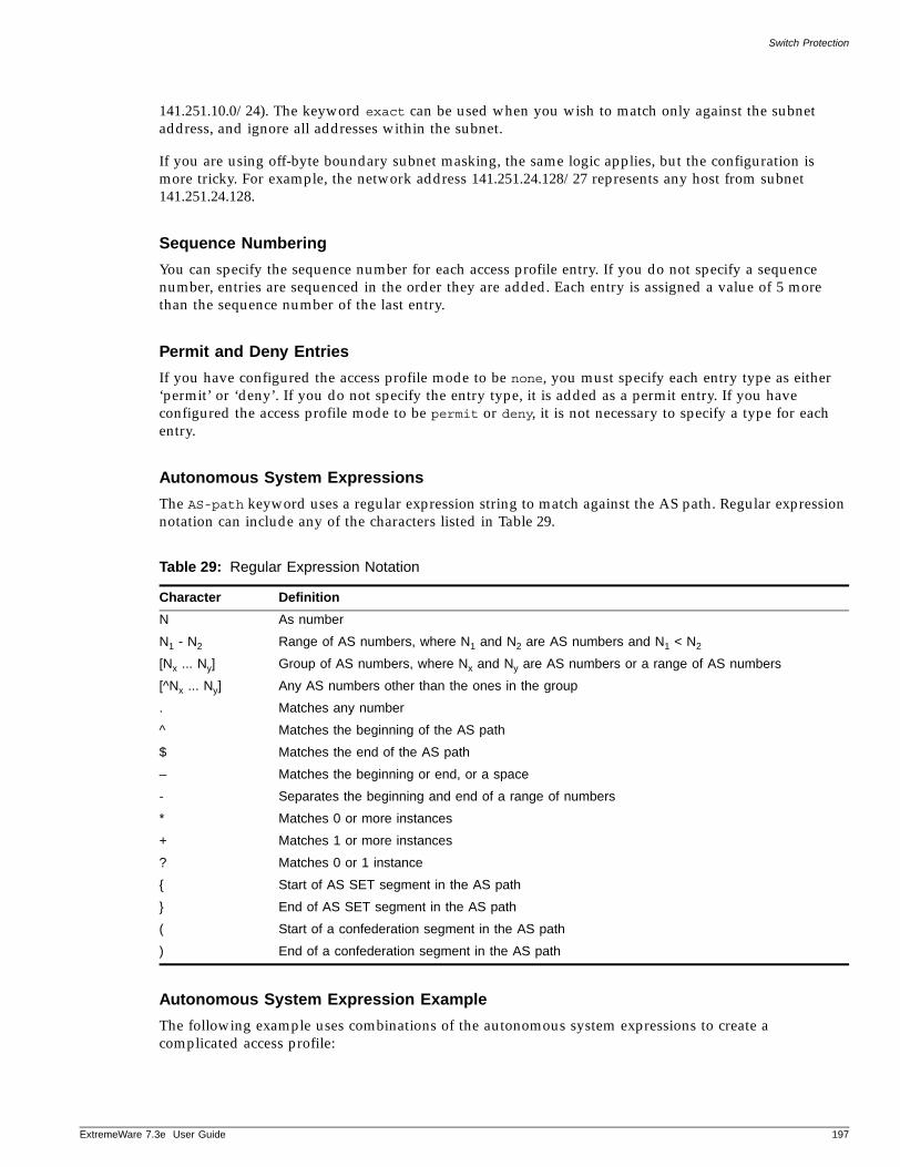
Switch Protection
ExtremeWare 7
141.251.10.0/24). The keyword exact can be used when you wish to match only against the subnet address, and ignore all addresses within the subnet.
If you are using off-byte boundary subnet masking, the same logic applies, but the configuration is more tricky. For example, the network address 141.251.24.128/27 represents any host from subnet 141.251.24.128.
Sequence Numbering
You can specify the sequence number for each access profile entry. If you do not specify a sequence number, entries are sequenced in the order they are added. Each entry is assigned a value of 5 more than the sequence number of the last entry.
Permit and Deny Entries
If you have configured the access profile mode to be none, you must specify each entry type as either ‘permit’ or ‘deny’. If you do not specify the entry type, it is added as a permit entry. If you have configured the access profile mode to be permit or deny, it is not necessary to specify a type for each entry.
Autonomous System Expressions
The AS-path keyword uses a regular expression string to match against the AS path. Regular expression notation can include any of the characters listed in Table 29.
Autonomous System Expression Example
The following example uses combinations of the autonomous system expressions to create a complicated access profile:
Table 29: Regular Expression Notation
Character Definition
N As number
N1 - N2 Range of AS numbers, where N1 and N2 are AS numbers and N1 < N2
[Nx ... Ny] Group of AS numbers, where Nx and Ny are AS numbers or a range of AS numbers
[^Nx ... Ny] Any AS numbers other than the ones in the group
. Matches any number
^ Matches the beginning of the AS path
$ Matches the end of the AS path
– Matches the beginning or end, or a space
- Separates the beginning and end of a range of numbers
* Matches 0 or more instances
+ Matches 1 or more instances
? Matches 0 or 1 instance
{ Start of AS SET segment in the AS path
} End of AS SET segment in the AS path
( Start of a confederation segment in the AS path
) End of a confederation segment in the AS path
.3e User Guide 197
Security
create access-profile AS1 type as-pathconfigure access-profile AS1 mode none
These commands create the access profile.
configure access-profile AS1 add 5 permit as-path “^65535$”
This command configures the access profile to permit AS paths that contain only (begin and end with) AS number 65535.
configure access-profile AS1 add 10 permit as-path “^65535 14490$”
This command configures the access profile to permit AS paths beginning with AS number 65535, ending with AS number 14490, and containing no other AS paths.
configure access-profile AS1 add 15 permit as-path “^1 2-8 [11 13 15]$”
This command configures the access profile to permit AS paths beginning with AS number 1, followed by any AS number from 2 - 8, and ending with either AS number 11, 13, or 15.
configure access-profile AS1 add 20 deny as-path “111 [2-8]”
This command configures the access profile to deny AS paths beginning with AS number 111 and ending with any AS number from 2 - 8.
configure access-profile AS1 add 25 permit as-path “111 .?”
This command configures the access profile to permit AS paths beginning with AS number 111 and ending with any additional AS number, or beginning and ending with AS number 111.
Deleting an Access Profile EntryTo delete an access profile entry, use the following command:
configure access-profile <access profile> delete <seq_number>
Applying Access Profiles
Once the access profile is defined, apply it to one or more routing protocols or VLANs. When an access profile is applied to a protocol function (for example, the export of RIP routes) or a VLAN, this forms an access policy. A profile can be used by multiple routing protocol functions or VLANs, but a protocol function or VLAN can use only one access profile.
Routing Profiles for RIP
If you are using the RIP protocol, the switch can be configured to use an access profile to determine:
• Trusted Neighbor—Use an access profile to determine trusted RIP router neighbors for the VLAN on the switch running RIP. To configure a trusted neighbor policy, use the following command:
configure rip vlan [<vlan name> | all] trusted-gateway [<access profile> | none]
• Import Filter—Use an access profile to determine which RIP routes are accepted as valid routes. This policy can be combined with the trusted neighbor policy to accept selected routes only from a set of trusted neighbors. To configure an import filter policy, use the following command:
198 ExtremeWare 7.3e User Guide
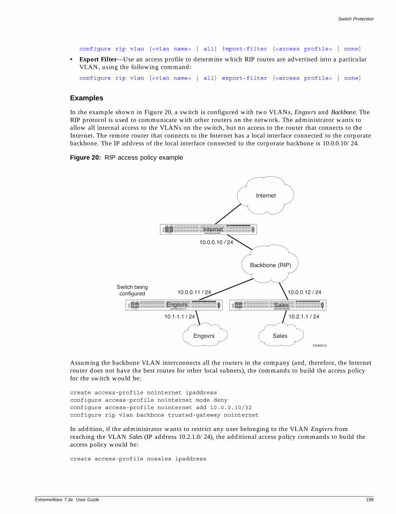
Switch Protection
ExtremeWare 7
configure rip vlan [<vlan name> | all] import-filter [<access profile> | none]
• Export Filter—Use an access profile to determine which RIP routes are advertised into a particular VLAN, using the following command:
configure rip vlan [<vlan name> | all] export-filter [<access profile> | none]
Examples
In the example shown in Figure 20, a switch is configured with two VLANs, Engsvrs and Backbone. The RIP protocol is used to communicate with other routers on the network. The administrator wants to allow all internal access to the VLANs on the switch, but no access to the router that connects to the Internet. The remote router that connects to the Internet has a local interface connected to the corporate backbone. The IP address of the local interface connected to the corporate backbone is 10.0.0.10/24.
Figure 20: RIP access policy example
Assuming the backbone VLAN interconnects all the routers in the company (and, therefore, the Internet router does not have the best routes for other local subnets), the commands to build the access policy for the switch would be:
create access-profile nointernet ipaddressconfigure access-profile nointernet mode denyconfigure access-profile nointernet add 10.0.0.10/32configure rip vlan backbone trusted-gateway nointernet
In addition, if the administrator wants to restrict any user belonging to the VLAN Engsvrs from reaching the VLAN Sales (IP address 10.2.1.0/24), the additional access policy commands to build the access policy would be:
create access-profile nosales ipaddress
ES4K013
Internet
Backbone (RIP)
SalesEngsvrs
Switch beingconfigured
10.0.0.10 / 24
10.0.0.11 / 24
10.1.1.1 / 24 10.2.1.1 / 24
10.0.0.12 / 24
Engsvrs Sales
Internet
.3e User Guide 199
Security
configure access-profile nosales mode denyconfigure access-profile nosales add 10.2.1.0/24configure rip vlan backbone import-filter nosales
This configuration results in the switch having no route back to the VLAN Sales.
Routing Access Profiles for OSPF
Because OSPF is a link-state protocol, the access profiles associated with OSPF are different in nature than those associated with RIP. Access profiles for OSPF are intended to extend the existing filtering and security capabilities of OSPF (for example, link authentication and the use of IP address ranges). If you are using the OSPF protocol, the switch can be configured to use an access profile to determine any of the following:
• Inter-area Filter—For switches configured to support multiple OSPF areas (an ABR function), an access profile can be applied to an OSPF area that filters a set of OSPF inter-area routes from being sourced from any other areas. To configure an inter-area filter policy, use the following command:
configure ospf area <area identifier> interarea-filter [<access profile> | none]
• External Filter—For switches configured to support multiple OSPF areas (an ABR function), an access profile can be applied to an OSPF area that filters a set of OSPF external routes from being advertised into that area. To configure an external filter policy, use the following command:
configure ospf area <area identifier> external-filter [<access profile> |none]
NOTE
If any of the external routes specified in the filter have already been advertised, those routes will remain until the associated LSAs in that area time-out.
• ASBR Filter—For switches configured to support RIP and static route re-distribution into OSPF, an access profile can be used to limit the routes that are advertised into OSPF for the switch as a whole. To configure an ASBR filter policy, use the following command:
configure ospf asbr-filter [<access profile> | none]
• Direct Filter—For switches configured to support direct route re-distribution into OSPF, an access profile can be used to limit the routes that are advertised into OSPF for the switch as a whole. To configure a direct filter policy, use the following command:
configure ospf direct-filter [<access profile> | none]
Example
Figure 21 illustrates an OSPF network that is similar to the network used previously in the RIP example. In this example, access to the Internet is accomplished by using the ASBR function on the switch labeled Internet. As a result, all routes to the Internet will be done through external routes. Suppose the network administrator wishes to only allow access to certain internet addresses falling within the range 192.1.1.0/24 to the internal backbone.
200 ExtremeWare 7.3e User Guide
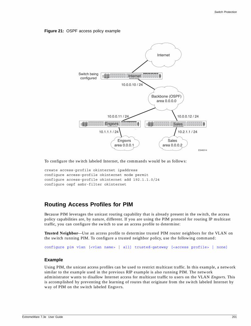
Switch Protection
ExtremeWare 7
Figure 21: OSPF access policy example
To configure the switch labeled Internet, the commands would be as follows:
create access-profile okinternet ipaddressconfigure access-profile okinternet mode permitconfigure access-profile okinternet add 192.1.1.0/24configure ospf asbr-filter okinternet
Routing Access Profiles for PIM
Because PIM leverages the unicast routing capability that is already present in the switch, the access policy capabilities are, by nature, different. If you are using the PIM protocol for routing IP multicast traffic, you can configure the switch to use an access profile to determine:
Trusted Neighbor—Use an access profile to determine trusted PIM router neighbors for the VLAN on the switch running PIM. To configure a trusted neighbor policy, use the following command:
configure pim vlan [<vlan name> | all] trusted-gateway [<access profile> | none]
Example
Using PIM, the unicast access profiles can be used to restrict multicast traffic. In this example, a network similar to the example used in the previous RIP example is also running PIM. The network administrator wants to disallow Internet access for multicast traffic to users on the VLAN Engsvrs. This is accomplished by preventing the learning of routes that originate from the switch labeled Internet by way of PIM on the switch labeled Engsvrs.
ES4K014
Internet
Backbone (OSPF)area 0.0.0.0
Salesarea 0.0.0.2
Engsvrsarea 0.0.0.1
10.0.0.10 / 24
10.0.0.11 / 24
10.1.1.1 / 24 10.2.1.1 / 24
10.0.0.12 / 24
Switch beingconfigured
Engsvrs Sales
Internet
.3e User Guide 201
Security
Denial of Service Protection
A Denial-of-Service (DoS) attack occurs when a critical network or computing resource is overwhelmed and rendered inoperative in a way that legitimate requests for service cannot succeed. In its simplest form, a Denial of Service attack is indistinguishable from normal heavy traffic. Extreme Network switches are not vulnerable to this simple attack because they are all designed to process packets in hardware at wire speed. However, there are some operations in any switch or router that are more costly than others, and although normal traffic is not a problem, exception traffic must be handled by the switch’s CPU in software.
Some packets that the switch processes in the CPU software include:
• Learning new traffic
• Routing and control protocols including ICMP and OSPF
• Switch management traffic (switch access by Telnet, SSH, HTTP, SNMP, etc...)
• Other packets directed to the switch that must be discarded by the CPU
If any one of these functions is overwhelmed, the CPU can be too busy to service other functions and cause switch performance to suffer. Even with the fast CPU of the Summit “e” series, there are ways to overwhelm the CPU with packets requiring costly processing.
DoS Protection is designed to help prevent this degraded performance by attempting to characterize the problem and filter out the offending traffic so that other functions can continue.
NOTE
DoS Protection can create an ACL at any one time for only one specific source. Only one ACL can be active at any time, so when the switch is suffering an attack from multiple hosts, the CPU will still get flooded.
Summit 200 and Summit 300. When a flood of packets is received from the switch, DoS Protection will count these packets. When the packet count nears the alert threshold, packets headers are saved. If the threshold is reached, then these headers are analyzed, and a hardware access control list (ACL) is created to limit the flow of these packets to the CPU. This ACL remains in place to provide relief to the CPU. Periodically, the ACL expires, and if the attack is still occurring, it is re-enabled. With the ACL in place, the CPU will have the cycles to process legitimate traffic and continue other services.
Summit 200 and Summit 300 users should configure per port DoS alert thresholds and time intervals to block the port against broadcast storms or learned packets.
Summit 400 only. When the number of packets entering the CPU reaches the alert threshold, the headers of the packets are analyzed and an ACL is created to limit the flow of these packets to the CPU. An ACL still cannot stop the packets from reaching the CPU because of conditions such as a layer 3 miss to the CPU or because of an unknown IP multicast error. The Summit 400 uses port-level blocking in conjunction with the ACL to block the packets.
Configuring Denial of Service ProtectionTo configure denial of service protection on a system-wide basis, use the following command:
202 ExtremeWare 7.3e User Guide
Denial of Service Protection
ExtremeWare 7
configure cpu-dos-protect [alert-threshold <packets per second>] [notice-threshold <packets per second>] [timeout <seconds>] [messages [on | off]] [filter-precedence <number>] [filter-type-allowed {destination | source | destination source} {protocol}]
The default values for the parameters are as follows:
• alert-threshold—4000 packets per second
• notice-threshold—4000 packets per second
• timeout—15 seconds
• messages—on (messages are sent to syslog)
• filter-precedence—10
• filter-type-allowed—destination
• trusted ports—none
If you wish to set all the parameters back to their default values, use the following command:
unconfigure cpu-dos-protect
NOTE
If you set the filter-precedence to 0, the ACLs created by DoS protection will be overwritten by the default VLAN QoS profile.
To start protecting the switch from attack on a port-basis, first determine what ports are at risk and set limits for the traffic on those ports. Use the following command to identify those ports and to configure the alert-threshold, also known as the disable threshold:
configure cpu-dos-protect [ports <portnumber> |all] alert-threshold <pkts> interval-time <seconds>
You can also configure all the ports on the switch to globally implement DoS using the following default values:
• alert-threshold—150 packets per second
• interval-time—1 seconds
Enabling Denial of Service ProtectionEnable denial of service protection using the following command:
enable cpu-dos-protect
Once enabled, denial of service protection creates an access list for packets when the receive packet on a port is greater than the alert level. For example, if cpu-dos-protect is enabled on a switch and the threshold alert level is set to 3000 packets per second, an access list is created if one of the ports on the switch receives 3000 or more packets per second. The precedence is set at 10 for the duration of the timeout.
For example, if you set the timeout to 15 seconds, the ACL is created for 15 seconds. The switch continues to create access lists for the duration of the timeout until the packet rate declines to less than the configured threshold alert level.
.3e User Guide 203
Security
Disabling Denial of Service ProtectionTo disable denial of service protection, use the following command:
disable cpu-dos-protect
Displaying Denial of Service Settings
To display denial of service settings and the status of the access list, use the following command:
show cpu-dos-protect [ports <portnumber>]CPU DoS Protection must be enabled for the show command to have valid values.
For example, to review the DoS traffic for port 1, issue this command:
sh cpu-dos-protect ports 1
The output from this command follows:
* ex160:22 # sh cpu-dos-protect ports 1
Cpu dos protect: enabled
Port L3Miss L3Err Bcast IpUnkMcast Learn Curr Int Cfg Thr Cfg Int Pass______________________________________________________________________1 150 150 150 150 150 1 150 1 3
Trusted ports: none
The output of this show command displays the following information, which can help you analyze the type of activity coming across the port to the CPU:
• The status of DoS Protection on the port
• Layer 3 miss to the CPU
These are packets that do not have corresponding IPFDB entries on VLANs, which are enabled for IP forwarding. Packets that are unicasted to the CPU IP are also considered in this category.
• Layer 3 error
These are IP packets with options, IPMC packets (but not class D address) with checksum errors, and non-IP packets.
• Broadcast traffic
• IP multicast unknown
These are IPMC packets that do not have corresponding IPMC FDB entries.
• Learning packets
These are packets that do not have a corresponding FDB entries.
• Current interval
The current time interval, less than or equal to the configured interval.
• Configured alert threshold
The maximum number of packets that can be sent to the CPU during the configured interval. This variable is equal to the configured interval parameter in seconds for each traffic category.
• Configured interval
204 ExtremeWare 7.3e User Guide
Denial of Service Protection
ExtremeWare 7
This variable is equal to the configured interval parameter in seconds for each traffic category.
• Free pass indicator (Zero in this field indicates a free pass for three intervals after the port comes up.)
• Trusted port status
How to Deploy DoS Protection
The conservative way to deploy DoS Protection is to use the simulated mode first. In simulated mode, DoS Protection is enabled, but no ACLs are generated. To enable the simulated mode, use the command:
enable cpu-dos-protect simulated
Next, configure the notice threshold. This will help determine the actual traffic received by the CPU by logging when the traffic exceeds the threshold. This can help understand the types of traffic encountered, and evaluate whether legitimate traffic may be accidentally blocked. Some examples of heavy legitimate traffic to the cpu include:
• route loss—during this period, the switch may receive lots of routing updates that cause heavy traffic processing loads on the CPU.
• configuration or image upload/download
To configure the notice threshold, use the following command:
configure cpu-dos-protect notice-threshold <packets per second>
Next, configure the alert threshold. If the alert threshold is reached, a simulated ACL is put in place. Although packets will not be dropped, this provides good information about the heavy traffic, which might be legitimate or might be an attack. The Ethernet address of the source and the type of traffic can be characterized by the type of ACL put in place. This is another way to judge if legitimate traffic would have been cut off. To configure the alert threshold, use the following command:
configure cpu-dos-protect alert-threshold <packets per second>
After normal traffic is characterized, steps should be taken to set:
• the appropriate notice level if some warning is desired
• the appropriate alert level at which an ACL is put in place
• trusted ports from which traffic won’t be blocked
In some cases, traffic from a switch port or group of ports will never cause an attack. These ports can be configured as trusted port and will never be considered for traffic that will generate an ACL. This can prevent innocent hosts from being blocked, or ensure that when an innocent host responds to an attack that the flood of response packets is not mistaken for the attack. To configure a trusted port on a system-wide basis, use the following command:
configure cpu-dos-protect trusted-ports [add <port number> | delete <port number> | all | none]
To configure a trusted port on a port-basis, use the following command:
configure cpu-dos-protect trusted-ports <port number>
.3e User Guide 205
Security
The last step is to enable DoS Protection. At this point, only attack traffic should be blocked and legitimate traffic should pass through. To enable the creation of ACLs for DoS Protection, use the following command:
enable cpu-dos-protect
Blocking SQL Slammer DoS AttacksYou can block the SQL Slammer DoS attack. SQL Slammer causes high CPU utilization on the next-hop switch serving multicast requests as ICMP sender entries are quickly populated into the multicast sender list. This leads to a high number of multicast entries in the IGMP snooping entry table, and a message similar to the following in the system log:
<WARN:HW> tBGTask: Reached maximum otp ExtraMC index allocation
To block and clean up after this task:
1 Block the attack by creating an ACL to block port 1434 using the following command:
create access-mask udp-mask ip-protocol dest-L4port
create access-list udp-acl udp-mask ip-protocol udp dest-L4port 1434 deny
2 Remove affected SQL servers from the network
You can simply disable the port connecting the server.
3 Clean up the existing IGMP snooping entries and IPMC cache using the following commands:
igmp snooping
clear ipmc cache
4 Disable IGMP snooping on the affected switches.
Disabling IGMP snooping affects routing protocols using multicast addresses and multicast traffic on that switch.
Improving Performance with Enhanced DoS ProtectionStandard DoS Protection installs an Access Control List (ACL) to protect against Internet Control Message Protocol (ICMP) attacks. To counter the reduced CPU time for processing real data and control packets as a result of an ICMP attack, DoS Protection creates an ACL based on the number of ICMP packets being handled by the CPU. ACLs can also affect real traffic, resulting in a performance cost.
Enhanced DoS Protection provides a complimentary level of security that allows detection and protection against attacks that have an address sweep signature. It does this in two ways:
• First, Enhanced DoS Protection allows you to limit the rate of unresolved IP packets that reach the CPU in case of a DoS attack.
• Second, Enhanced DoS Protection identifies valid streams before installing IPFDB entries, reducing IPFDB thrashing.
To enable Enhanced DoS Protection globally, use the following command without any keywords:
enable enhanced-dos-protect {rate-limit | ipfdb} {ports [<portlist> | all]}
To disable Enhanced DoS Protection globally, use the following command without any keywords:
disable enhanced-dos-protect {rate-limit | ipfdb} {ports [<portlist> | all]}
206 ExtremeWare 7.3e User Guide
Denial of Service Protection
ExtremeWare 7
Configuring Ports as Trusted or Untrusted. Rate limiting is applied to packets arriving on untrusted ports. You can configure each port as trusted or untrusted. A trusted port behaves as a normal port. An untrusted port behaves according to the configuration parameter used in IPFDB thrashing. To configure a port as trusted or untrusted, use the following command:
configure enhanced-dos-protect ports [trusted | untrusted] <portlist>
Setting and Verifying Threshold Values. Rate limit threshold values can be configured for selected ports. If the number of packets received on an untrusted port reaches the configured threshold limit, the packets are randomly dropped. The number of packets dropped is proportional to the configured drop probability rate. For example, if the drop probability rate is set to 60%, then 60% of packets received after the configured threshold within the time duration to be considered (the learning window) will be dropped.
Use the threshold keyword in the following command to set rate limit thresholds:
configure enhanced-dos-protect rate-limit [threshold <threshold> | drop-probability
<drop-probability> | learn-window <learn-window> | protocol [all | icmp]] ports
<portlist>
Use the following command to verify the rate limit threshold configuration:
show enhanced-dos-protect [rate-limit | ipfdb] ports [<portlist> | all]
Use the threshold keyword in the following command to remove selected ports from the rate limit threshold configuration:
unconfigure enhanced-dos-protect rate-limit [threshold | drop-probability |
learn-window | protocol] ports <portlist>
Setting and Verifying Learn Window Values. You can specify learn window values for selected ports by using the learn-window keyword in the following command:
configure enhanced-dos-protect rate-limit [threshold <threshold> | drop-probability
<drop-probability> | learn-window <learn-window> | protocol [all | icmp]] ports
<portlist>
Use the following command to verify the learn window configuration:
show enhanced-dos-protect [rate-limit | ipfdb] ports [<portlist> | all]
Use the learn-window keyword in the following command to remove selected ports from the rate limit learn window configuration:
unconfigure enhanced-dos-protect rate-limit [threshold | drop-probability |
learn-window | protocol] ports <portlist>
Setting and Verifying Drop Probability Rates. You can specify the percentage of slow-path traffic to be dropped by using the drop-probability keyword in the following command:
configure enhanced-dos-protect rate-limit [threshold <threshold> | drop-probability
<drop-probability> | learn-window <learn-window> | protocol [all | icmp]] ports
<portlist>
Use the following command to verify the drop probability configuration:
.3e User Guide 207
Security
show enhanced-dos-protect [rate-limit | ipfdb] ports [<portlist> | all]
Use the drop-probability keyword in the following command to remove selected ports from the rate limit drop probability configuration:
unconfigure enhanced-dos-protect rate-limit [threshold | drop-probability |
learn-window | protocol] ports <portlist>
Setting and Verifying Protocol Types. To change the rate limit protocol type, use the protocol keyword in the following command:
configure enhanced-dos-protect rate-limit [threshold <threshold> | drop-probability
<drop-probability> | learn-window <learn-window> | protocol [all | icmp]] ports
<portlist>
Use the following command to verify the drop probability configuration:
show enhanced-dos-protect [rate-limit | ipfdb] ports [<portlist> | all]
Use the protocol keyword in the following command to remove selected ports from the rate limit protocol configuration:
unconfigure enhanced-dos-protect rate-limit [threshold | drop-probability |
learn-window | protocol] ports <portlist>
Configuring the IPFDB Learning Qualifier
Enhanced DoS Protection lets you configure an IPFDB learning qualifier to identify valid IP streams before installing IPFDB entries. IPFDB entries are installed only for valid IP flows, which reduces IPFDB thrashing. An IP stream is considered valid only if it meets the qualification criteria, which include a defined learning threshold and aging time. If the number of packets received for a given IP stream is greater than the defined learning threshold during the defined aging time, the stream is considered valid and the entry is installed.
Enabling and Disabling the IPFDB Learning Qualifier. To globally enable reduced IPFDB thrashing, use the ipfdb keyword without any port qualification in the following command:
enable enhanced-dos-protect {rate-limit | ipfdb} {ports [<portlist> | all]}
To globally disable reduced IPFDB thrashing, use the ipfdb keyword without any port qualification in the following command:
disable enhanced-dos-protect {rate-limit | ipfdb} {ports [<portlist> | all]}
To enable reduced IPFDB thrashing for specific ports, use the ipfdb and port keywords in the following command:
enable enhanced-dos-protect {rate-limit | ipfdb} {ports [<portlist> | all]}
To disable reduced IPFDB thrashing for specific ports, use the ipfdb and port keywords in the following command:
disable enhanced-dos-protect {rate-limit | ipfdb} {ports [<portlist> | all]}
To verify that reduced IPFDB thrashing is enabled or disabled, use the ipfdb keyword in the following command:
208 ExtremeWare 7.3e User Guide
Denial of Service Protection
ExtremeWare 7
show enhanced-dos-protect [rate-limit | ipfdb] ports [<portlist> | all]
Configuring Ports as Trusted or Untrusted. You can configure each port as trusted or untrusted. A trusted port behaves as a normal port. An untrusted port behaves according to the configuration parameter used in IPFDB thrashing. To configure a port as trusted or untrusted, use the following command:
configure enhanced-dos-protect ports [trusted | untrusted] <portlist>
Setting and Verifying the Learning Limit. You can configure a learning limit value to define the number of packets to be counted before ExtremeWare can create an IPFDB entry in the hardware. To configure the learning limit, use the following command:
configure enhanced-dos-protect ipfdb learn-limit <learn-limit> ports <portlist>
To verify the status of reduced IPFDB thrashing for each port, use the ipfdb keyword in the following command and view data in the Learn-Limit column:
show enhanced-dos-protect [rate-limit | ipfdb] ports [<portlist> | all]
Setting and Verifying the Learn Window. You can set a learn window value used by the switch to wait for a certain amount of time to reach the threshold value. Use the following command to set the learn window for the IPFDB learning qualifier:
configure enhanced-dos-protect ipfdb learn-window <learn-window> ports <portlist>
To verify the status of reduced IPFDB thrashing for each port, use the ipfdb keyword in the following command and view data in the Learn-Window column:
show enhanced-dos-protect [rate-limit | ipfdb] ports [<portlist> | all]
Setting and Verifying the Aging Value. You can set an aging value that defines the software cache timeout period that the switch will wait to delete an IPFDB entry. To set the aging value, use the following command:
configure enhanced-dos-protect ipfdb agingtime <aging> ports <portlist>
To verify the aging value status of reduced IPFDB thrashing for each port, use the ipfdb keyword in the following command and view data in the Aging column:
show enhanced-dos-protect [rate-limit | ipfdb] ports [<portlist> | all]
Configuring the IPFDB Cache Size. Enhanced DoS Protection maintains the number of IPFDB entries according to the cache-size limit. To set the cache size, use the following command:
configure enhanced-dos-protect ipfdb cache-size <cache-size>
To verify the cache-size status of the IPFDB learning qualifier, use the ipfdb keyword in the following command:
show enhanced-dos-protect [rate-limit | ipfdb] ports [<portlist> | all]
.3e User Guide 209
Security
Duplicate IP Protection
Duplicate IP protection is designed to allow only those hosts whose IP addresses are assigned by a DHCP server to access the network. The process works by disabling ARP learning. Hosts with manually configured IP addresses are not able to access the network because the switch does not follow the ARP procedures to create its ARP table. Since all clients’ IP addresses can be centrally managed and allocated, duplicate IP protection can increase network security, provide better user management, keep network operation from being interrupted by IP address duplication, and benefit IP address based accounting and billing. By default, arp-learning is enabled on all ports and vlans.
When a packet is forwarded through routing, the destination IP address is generally compared with information in the hardware forwarding entry. The information used for comparison enables classification into two categories: host lookup and network lookup
To enable the ARP-learning feature on the switch, use the following command:
enable arp-learning
To disable the ARP-learning feature, use the following command.
disable arp-learning
To enable arp-learning on a port, use the following command:
enable arp-learning ports <portlist>
To disable arp-learning on a port, use the following command:
disable arp-learning ports <portlist>
To display the arp-learning configuration on ports, use the following command:
show arp-learning vlan <vlan name> port <portlist>
To enable arp-learning on a vlan, use the following command:
enable arp-learning vlan <vlan name> port <portlist>
To disable arp-learning on a vlan, use the following command;
disable arp-learning vlan <vlan name>
To display the arp-learning configuration on this vlan, use the following command:
show arp-learning vlan <vlan name> port <portlist>
To enable arp-learning on a port in the given vlan, use the following command:
enable arp-learning vlan <vlan name> port <portlist>
To disable arp-learning on a port in the given vlan, use the following command:
disable arp-learning vlan <vlan name> port <portlist>
To display the arp-learning configuration a port in the given vlan, use the following command:
show arp-learning vlan <vlan name> port <portlist>
210 ExtremeWare 7.3e User Guide
Management Access Security
ExtremeWare 7
Management Access Security
Management access security features control access to the management functions available on the switch. These features help insure that any configuration changes to the switch can only be done by authorized users. In this category are the following features:
• Authenticating Users Using RADIUS or TACACS+
• Configuring Timeout
Authenticating Users Using RADIUS or TACACS+
ExtremeWare provides two methods to authenticate users who login to the switch:
• RADIUS client
• TACACS+
RADIUS ClientRemote Authentication Dial In User Service (RADIUS, RFC 2138) is a mechanism for authenticating and centrally administrating access to network nodes. The ExtremeWare RADIUS client implementation allows authentication for Telnet, Vista, or console access to the switch.
You can define a primary and secondary RADIUS server for the switch to contact. When a user attempts to login using Telnet, http, or the console, the request is relayed to the primary RADIUS server, and then to the secondary RADIUS server, if the primary does not respond. If the RADIUS client is enabled, but access to the RADIUS primary and secondary server fails, the switch uses its local database for authentication.
The privileges assigned to the user (admin versus nonadmin) at the RADIUS server take precedence over the configuration in the local switch database.
To configure the RADIUS servers, use the following command:
configure radius [primary | secondary] server [<ipaddress> | <hostname>] {<udp_port>} client-ip [<ipaddress>]
To configure the timeout if a server fails to respond, use the following command:
configure radius {[primary | secondary] {server [<ipaddress>]|<hostname>}} timeout <seconds>
Configuring the Shared Secret Password
In addition to specifying the RADIUS server IP information, RADIUS also contains a means to verify communication between network devices and the server. The shared secret is a password configured on the network device and RADIUS server, used by each to verify communication.
To configure the shared secret for RADIUS servers, use the following command:
configure radius [primary | secondary] {server <ipaddress>|<hostname>} shared-secret {encrypted} [<string>]
.3e User Guide 211
Security
Enabling and Disabling RADIUS
After server information is entered, you can start and stop RADIUS authentication as many times as necessary without needing to reconfigure server information.
To enable RADIUS authentication, use the following command:
enable radius
To disable RADIUS authentication, use the following command:
disable radius
Configuring RADIUS Accounting
Extreme switches are capable of sending RADIUS accounting information. As with RADIUS authentication, you can specify two servers for receipt of accounting information. You can configure RADIUS accounting servers to be the same as the authentication servers, but this is not required.
To specify RADIUS accounting servers, use the following command:
configure radius-accounting [primary | secondary] server [<ipaddress> | <hostname>] {<udp_port>} client-ip [<ipaddress>]
To configure the timeout if a server fails to respond, use the following command:
configure radius-accounting {[primary | secondary] {server <ipaddress> | <hostname>}} timeout <seconds>
RADIUS accounting also makes use of the shared secret password mechanism to validate communication between network access devices and RADIUS accounting servers.
To specify shared secret passwords for RADIUS accounting servers, use the following command:
configure radius-accounting [primary | secondary] {server <ipaddress>|<hostname>} shared-secret {encrypted} [<string>]
After you configure RADIUS accounting server information, you must enable accounting before the switch begins transmitting the information. You must enable RADIUS authentication for accounting information to be generated. You can enable and disable accounting without affecting the current state of RADIUS authentication.
To enable RADIUS accounting, use the following command:
enable radius-accounting
To disable RADIUS accounting, use the following command:
disable radius-accounting
Per-Command Authentication Using RADIUS
The RADIUS implementation can be used to perform per-command authentication. Per-command authentication allows you to define several levels of user capabilities by controlling the permitted command sets based on the RADIUS username and password. You do not need to configure any additional switch parameters to take advantage of this capability. The RADIUS server implementation
212 ExtremeWare 7.3e User Guide
Authenticating Users Using RADIUS or TACACS+
ExtremeWare 7
automatically negotiates the per-command authentication capability with the switch. For examples on per-command RADIUS configurations, see the next section.
Configuring RADIUS Client
You can define primary and secondary server communication information, and for each RADIUS server, the RADIUS port number to use when talking to the RADIUS server. The default port value is 1645. The client IP address is the IP address used by the RADIUS server for communicating back to the switch.
RADIUS RFC 2138 Attributes
The RADIUS RFC 2138 optional attributes supported are as follows:
• User-Name
• User-Password
• Service-Type
• Login-IP-Host
Using RADIUS Servers with Extreme Switches
Extreme Networks switches have two levels of user privilege:
• Read-only
• Read-write
Because there are no CLI commands available to modify the privilege level, access rights are determined when you log in. For a RADIUS server to identify the administrative privileges of a user, Extreme switches expect a RADIUS server to transmit the Service-Type attribute in the Access-Accept packet, after successfully authenticating the user.
Extreme switches grant a RADIUS-authenticated user read-write privilege if a Service-Type value of 6 is transmitted as part of the Access-Accept message from the Radius server. Other Service-Type values, or no value, result in the switch granting read-only access to the user. Different implementations of RADIUS handle attribute transmission differently. You should consult the documentation for your specific implementation of RADIUS when you configure users for read-write access.
Cistron RADIUS
Cistron RADIUS is a popular server, distributed under GPL. Cistron RADIUS can be found at:
http://www.miquels.cistron.nl/radius/
When you configure the Cistron server for use with Extreme switches, you must pay close attention to the users file setup. The Cistron RADIUS dictionary associates the word Administrative-User with Service-Type value 6, and expects the Service-Type entry to appear alone on one line with a leading tab character.
The following is a user file example for read-write access:
adminuser Auth-Type = System
Service-Type = Administrative-User,
Filter-Id = “unlim”
.3e User Guide 213
Security
Livingston (Lucent) RADIUS
Livingston RADIUS is produced by Lucent Technologies primarily for use with their portmaster products. Version 2.1 is released under a BSD license agreement and can be found at ftp://ftp.livingston.com/pub/le/radius/radius21.tar.Z. As with Cistron RADIUS, the Livingston server default dictionary associates Administrative-User with Service-Type value 6. The administrative users file entry example for Cistron RADIUS also works with Livingston RADIUS.
RSA Ace
For users of their SecureID product, RSA offers RADIUS capability as part of their ACE server software. With some versions of ACE, the RADIUS shared-secret is incorrectly sent to the switch resulting in an inability to authenticate. As a work around, do not configure a shared-secret for RADIUS accounting and authentication servers on the switch.
Limiting Max-Concurrent Sessions with Funk Software’s Steel Belted Radius
For users who have Funk Software’s Steel Belted Radius (SBR) server, it is possible to limit the number of concurrent login sessions using the same user account. This feature allows the use of shared user accounts, but limits the number of simultaneous logins to a defined value. Using this feature requires Funk Software Steel-Belted-Radius for Radius Authentication & Accounting.
Complete the following two steps to limit the maximum concurrent login sessions under the same user account:
1 Configure Radius and Radius-Accounting on the switch
The Radius and Radius-Accounting servers used for this feature must reside on the same physical Radius server. Standard Radius and Radius-Accounting configuration is required as described earlier in this chapter.
2 Modify the Funk SBR ‘vendor.ini’ file and user accounts
To configure the Funk SBR server, the file ‘vendor.ini’ must be modified to change the Extreme Networks configuration value of ‘ignore-ports’ to yes as shown in the example below:
vendor-product = Extreme Networksdictionary = Extremeignore-ports = yesport-number-usage = per-port-typehelp-id = 2000
After modifying the ‘vendor.ini’ file, the desired user accounts must be configured for the Max-Concurrent connections. Using the SBR Administrator application, enable the check box for ‘Max-Concurrent connections’ and fill in the desired number of maximum sessions.
Extreme RADIUS
Extreme Networks provides its users, free of charge, a radius server based on Merit RADIUS. Extreme RADIUS provides per-command authentication capabilities in addition to the standard set of radius features. Source code for Extreme RADIUS can be obtained from the Extreme Networks Technical Assistance Center and has been tested on Red Hat Linux and Solaris.
When Extreme RADIUS is up and running, the two most commonly changed files will be users and profiles. The users file contains entries specifying login names and the profiles used for per-command authentication after they have logged in. Sending a HUP signal to the RADIUS process is sufficient to get changes in the users file to take place. Extreme RADIUS uses the file named profiles to specify
214 ExtremeWare 7.3e User Guide
Authenticating Users Using RADIUS or TACACS+
ExtremeWare 7
command lists that are either permitted or denied to a user based on their login identity. Changes to the profiles file require the RADIUS server to be shutdown and restarted. Sending a HUP signal to the RADIUS process is not enough to force changes to the profiles file to take effect.
When you create command profiles, you can use an asterisk to indicate any possible ending to any particular command. The asterisk cannot be used as the beginning of a command. Reserved words for commands are matched exactly to those in the profiles file. Due to the exact match, it is not enough to simply enter “sh” for “show” in the profiles file, the complete word must be used. Commands can still be entered in the switch in partial format.
When you use per-command authentication, you must ensure that communication between the switch(es) and radius server(s) is not lost. If the RADIUS server crashes while users are logged in, they will have full administrative access to the switch until they log out. Using two RADIUS servers and enabling idle timeouts on all switches will greatly reduce the chance of a user gaining elevated access due to RADIUS server problems.
RADIUS Server Configuration Example (Merit)
Many implementations of RADIUS server use the publicly available Merit© AAA server application, available on the World Wide Web at:
http://www.merit.edu/aaa
Included below are excerpts from relevant portions of a sample Merit RADIUS server implementation. The example shows excerpts from the client and user configuration files. The client configuration file (ClientCfg.txt) defines the authorized source machine, source name, and access level. The user configuration file (users) defines username, password, and service type information.
ClientCfg.txt
#Client Name Key [type] [version] [prefix]#---------------- --------------- -------------- --------- --------#10.1.2.3:256 test type = nas v2 pfx#pm1 %^$%#*(&!(*&)+ type=nas pm1.#pm2 :-):-(;^):-}! type nas pm2.#merit.edu/homeless hmoemreilte.ses#homeless testing type proxy v1#xyz.merit.edu moretesting type=Ascend:NAS v1#anyoldthing:1234 whoknows? type=NAS+RAD_RFC+ACCT_RFC10.202.1.3 andrew-linux type=nas10.203.1.41 eric type=nas10.203.1.42 eric type=nas10.0.52.14 samf type=nas
users
user Password = ""Filter-Id = "unlim"
admin Password = "", Service-Type = AdministrativeFilter-Id = "unlim"
eric Password = "", Service-Type = AdministrativeFilter-Id = "unlim"
albert Password = "password", Service-Type = AdministrativeFilter-Id = "unlim"
.3e User Guide 215
Security
samuel Password = "password", Service-Type = AdministrativeFilter-Id = "unlim"
RADIUS Per-Command Configuration Example
Building on this example configuration, you can use RADIUS to perform per-command authentication to differentiate user capabilities. To do so, use the Extreme-modified RADIUS Merit software that is available from the Extreme Networks by contacting Extreme Networks technical support. The software is available in compiled format for Solaris™ or Linux™ operating systems, as well as in source code format. For all clients that use RADIUS per-command authentication, you must add the following type to the client file:
type:extreme:nas + RAD_RFC + ACCT_RFC
Within the users configuration file, additional keywords are available for Profile-Name and Extreme-CLI-Authorization. To use per-command authentication, enable the CLI authorization function and indicate a profile name for that user. If authorization is enabled without specifying a valid profile, the user is unable to perform any commands.
Next, define the desired profiles in an ASCII configuration file called profiles. This file contains named profiles of exact or partial strings of CLI commands. A named profile is linked with a user through the users file. A profile with the permit on keywords allows use of only the listed commands. A profile with the deny keyword allows use of all commands except the listed commands.
CLI commands can be defined easily in a hierarchal manner by using an asterisk (*) to indicate any possible subsequent entry. The parser performs exact string matches on other text to validate commands. Commands are separated by a comma (,) or newline.
Looking at the following example content in profiles for the profile named PROFILE1, which uses the deny keyword, the following attributes are associated with the user of this profile:
• Cannot use any command starting with enable.
• Cannot issue the disable ipforwarding command.
• Cannot issue a show switch command.
• Can perform all other commands.
We know from the users file that this applies to the users albert and lulu. We also know that eric is able to log in, but is unable to perform any commands, because he has no valid profile assigned.
In PROFILE2, a user associated with this profile can use any enable command, the clear counters command and the show management command, but can perform no other functions on the switch. We also know from the users file that gerald has these capabilities.
The following lists the contents of the file users with support for per-command authentication:
user Password = ""Filter-Id = "unlim"
admin Password = "", Service-Type = AdministrativeFilter-Id = "unlim"
eric Password = "", Service-Type = Administrative, Profile-Name = ""Filter-Id = "unlim"Extreme:Extreme-CLI-Authorization = Enabled
216 ExtremeWare 7.3e User Guide
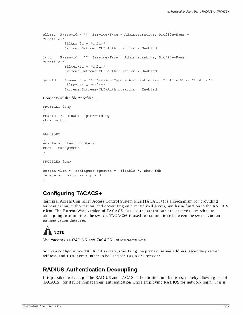
Authenticating Users Using RADIUS or TACACS+
ExtremeWare 7
albert Password = "", Service-Type = Administrative, Profile-Name ="Profile1"
Filter-Id = "unlim"Extreme:Extreme-CLI-Authorization = Enabled
lulu Password = "", Service-Type = Administrative, Profile-Name ="Profile1"
Filter-Id = "unlim"Extreme:Extreme-CLI-Authorization = Enabled
gerald Password = "", Service-Type = Administrative, Profile-Name "Profile2"Filter-Id = "unlim"Extreme:Extreme-CLI-Authorization = Enabled
Contents of the file “profiles”:
PROFILE1 deny{enable *, disable ipforwardingshow switch}
PROFILE2{enable *, clear countersshow management}
PROFILE3 deny{create vlan *, configure iproute *, disable *, show fdbdelete *, configure rip add}
Configuring TACACS+Terminal Access Controller Access Control System Plus (TACACS+) is a mechanism for providing authentication, authorization, and accounting on a centralized server, similar in function to the RADIUS client. The ExtremeWare version of TACACS+ is used to authenticate prospective users who are attempting to administer the switch. TACACS+ is used to communicate between the switch and an authentication database.
NOTE
You cannot use RADIUS and TACACS+ at the same time.
You can configure two TACACS+ servers, specifying the primary server address, secondary server address, and UDP port number to be used for TACACS+ sessions.
RADIUS Authentication DecouplingIt is possible to decouple the RADIUS and TACAS authentication mechanisms, thereby allowing use of TACACS+ for device management authentication while employing RADIUS for network login. This is
.3e User Guide 217
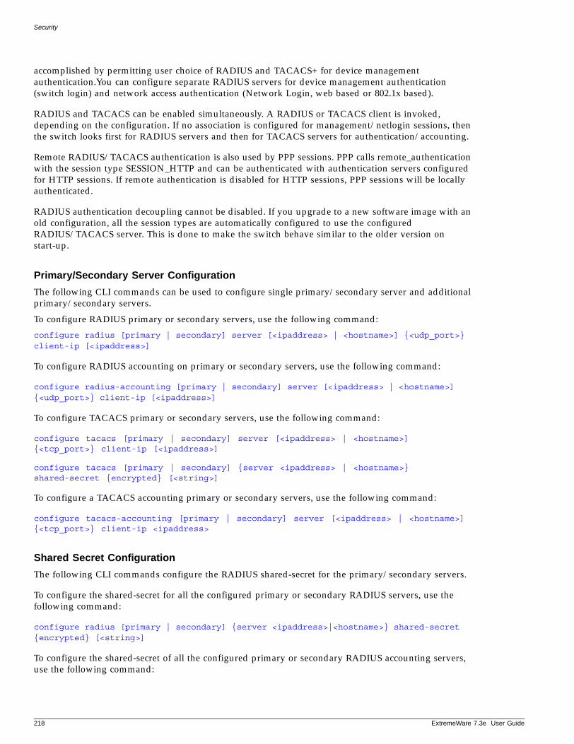
Security
accomplished by permitting user choice of RADIUS and TACACS+ for device management authentication.You can configure separate RADIUS servers for device management authentication (switch login) and network access authentication (Network Login, web based or 802.1x based).
RADIUS and TACACS can be enabled simultaneously. A RADIUS or TACACS client is invoked, depending on the configuration. If no association is configured for management/netlogin sessions, then the switch looks first for RADIUS servers and then for TACACS servers for authentication/accounting.
Remote RADIUS/TACACS authentication is also used by PPP sessions. PPP calls remote_authentication with the session type SESSION_HTTP and can be authenticated with authentication servers configured for HTTP sessions. If remote authentication is disabled for HTTP sessions, PPP sessions will be locally authenticated.
RADIUS authentication decoupling cannot be disabled. If you upgrade to a new software image with an old configuration, all the session types are automatically configured to use the configured RADIUS/TACACS server. This is done to make the switch behave similar to the older version on start-up.
Primary/Secondary Server Configuration
The following CLI commands can be used to configure single primary/secondary server and additional primary/secondary servers.
To configure RADIUS primary or secondary servers, use the following command:
configure radius [primary | secondary] server [<ipaddress> | <hostname>] {<udp_port>} client-ip [<ipaddress>]
To configure RADIUS accounting on primary or secondary servers, use the following command:
configure radius-accounting [primary | secondary] server [<ipaddress> | <hostname>] {<udp_port>} client-ip [<ipaddress>]
To configure TACACS primary or secondary servers, use the following command:
configure tacacs [primary | secondary] server [<ipaddress> | <hostname>] {<tcp_port>} client-ip [<ipaddress>]
configure tacacs [primary | secondary] {server <ipaddress> | <hostname>} shared-secret {encrypted} [<string>]
To configure a TACACS accounting primary or secondary servers, use the following command:
configure tacacs-accounting [primary | secondary] server [<ipaddress> | <hostname>] {<tcp_port>} client-ip <ipaddress>
Shared Secret Configuration
The following CLI commands configure the RADIUS shared-secret for the primary/secondary servers.
To configure the shared-secret for all the configured primary or secondary RADIUS servers, use the following command:
configure radius [primary | secondary] {server <ipaddress>|<hostname>} shared-secret {encrypted} [<string>]
To configure the shared-secret of all the configured primary or secondary RADIUS accounting servers, use the following command:
218 ExtremeWare 7.3e User Guide
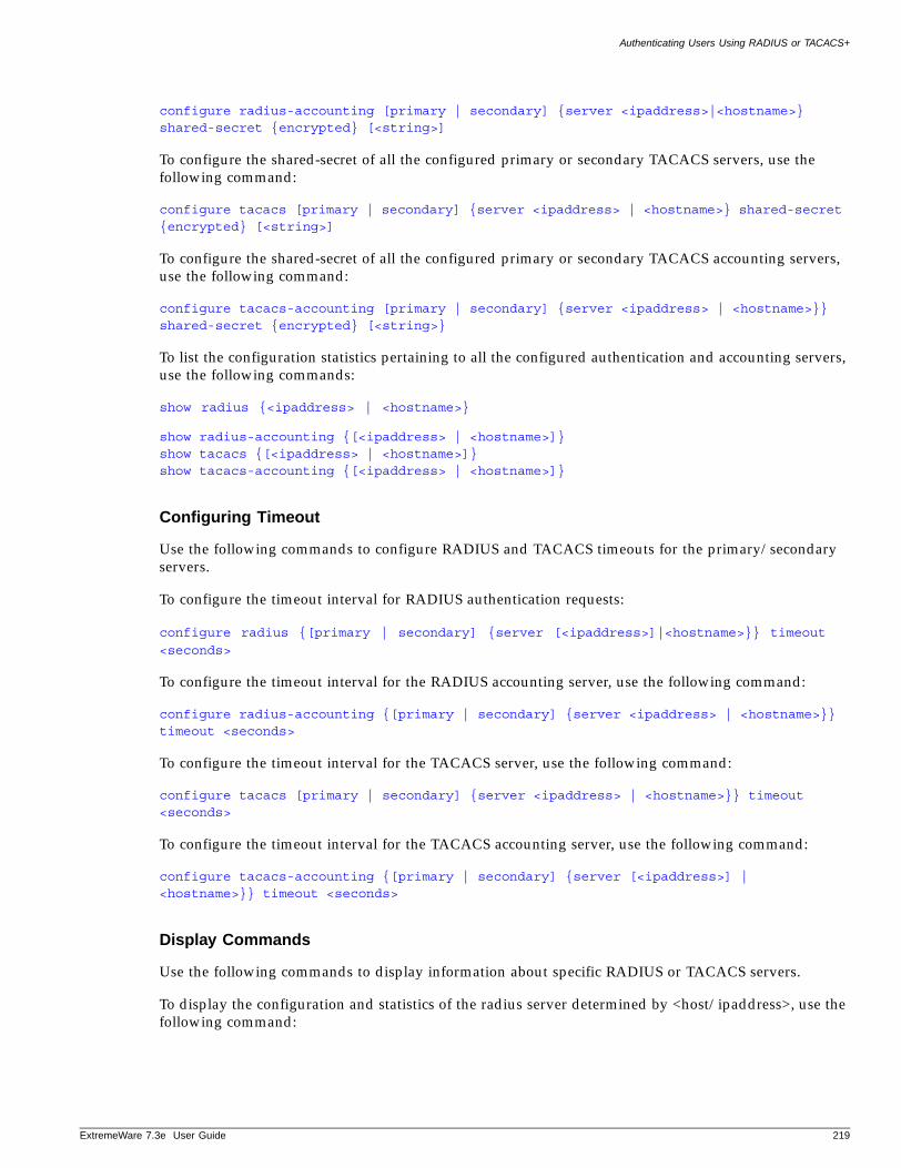
Authenticating Users Using RADIUS or TACACS+
ExtremeWare 7
configure radius-accounting [primary | secondary] {server <ipaddress>|<hostname>} shared-secret {encrypted} [<string>]
To configure the shared-secret of all the configured primary or secondary TACACS servers, use the following command:
configure tacacs [primary | secondary] {server <ipaddress> | <hostname>} shared-secret {encrypted} [<string>]
To configure the shared-secret of all the configured primary or secondary TACACS accounting servers, use the following command:
configure tacacs-accounting [primary | secondary] {server <ipaddress> | <hostname>}} shared-secret {encrypted} [<string>}
To list the configuration statistics pertaining to all the configured authentication and accounting servers, use the following commands:
show radius {<ipaddress> | <hostname>}
show radius-accounting {[<ipaddress> | <hostname>]}show tacacs {[<ipaddress> | <hostname>]}show tacacs-accounting {[<ipaddress> | <hostname>]}
Configuring Timeout
Use the following commands to configure RADIUS and TACACS timeouts for the primary/secondary servers.
To configure the timeout interval for RADIUS authentication requests:
configure radius {[primary | secondary] {server [<ipaddress>]|<hostname>}} timeout
<seconds>
To configure the timeout interval for the RADIUS accounting server, use the following command:
configure radius-accounting {[primary | secondary] {server <ipaddress> | <hostname>}} timeout <seconds>
To configure the timeout interval for the TACACS server, use the following command:
configure tacacs [primary | secondary] {server <ipaddress> | <hostname>}} timeout <seconds>
To configure the timeout interval for the TACACS accounting server, use the following command:
configure tacacs-accounting {[primary | secondary] {server [<ipaddress>] | <hostname>}} timeout <seconds>
Display Commands
Use the following commands to display information about specific RADIUS or TACACS servers.
To display the configuration and statistics of the radius server determined by <host/ipaddress>, use the following command:
.3e User Guide 219
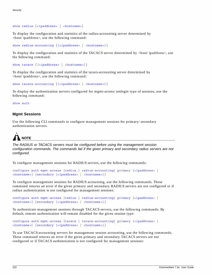
Security
show radius {<ipaddress> | <hostname>}
To display the configuration and statistics of the radius-accounting server determined by <host/ipaddress>, use the following command:
show radius-accounting {[<ipaddress> | <hostname>]}
To display the configuration and statistics of the TACACS server determined by <host/ipaddress>, use the following command:
show tacacs {[<ipaddress> | <hostname>]}
To display the configuration and statistics of the tacacs-accounting server determined by <host/ipaddress>, use the following command:
show tacacs-accounting {[<ipaddress> | <hostname>]}
To display the authentication servers configured for mgmt-access/netlogin type of sessions, use the following command:
show auth
Mgmt Sessions
Use the following CLI commands to configure management sessions for primary/secondary authentication servers.
NOTE
The RADIUS or TACACS servers must be configured before using the management session configuration commands. The commands fail if the given primary and secondary radius servers are not configured.
To configure management sessions for RADIUS servers, use the following commands:
configure auth mgmt-access [radius | radius-accounting] primary [<ipaddress> | <hostname>} {secondary [<ipaddress> | <hostname>]}
To configure management sessions for RADIUS accounting, use the following commands. These command returns an error if the given primary and secondary RADIUS servers are not configured or if radius authentication is not configured for management sessions:
configure auth mgmt-access [radius | radius-accounting] primary [<ipaddress> | <hostname>} {secondary [<ipaddress> | <hostname>]}
To authenticate management sessions through TACACS servers, use the following commands. By default, remote authentication will remain disabled for the given session type:
configure auth mgmt-access [tacacs | tacacs-accounting] primary [<ipaddress> | <hostname>] {secondary [<ipaddress> | <hostname>]}
To use TACACS-accounting servers for management session accounting, use the following commands. These command returns an error if the given primary and secondary TACACS servers are not configured or if TACACS authentication is not configured for management sessions:
220 ExtremeWare 7.3e User Guide
Secure Shell 2 (SSH2)
ExtremeWare 7
configure auth mgmt-access [tacacs | tacacs-accounting] primary [<ipaddress> | <hostname>] {secondary [<ipaddress> | <hostname>]}
To use the default configuration for management sessions, use the following command:
unconfigure auth mgmt-access
4.3.5Netlogin Sessions
The following CLI commands configure primary/secondary authentication servers for all the netlogin sessions. These commands are equivalent to configuring dot1x-netlogin and http-netlogin sessions.
To configure authentication for all the netlogin sessions by way of RADIUS servers, use the following commands. This command will fail if the given primary and secondary RADIUS servers are not configured:
configure auth netlogin [radius | radius-accounting] primary {<ipaddress> | <hostname>} {secondary [<ipaddress> | <hostname>]}
To configure RADIUS-accounting servers to account for netlogin sessions, use the following commands. These commands return an error if the given primary and secondary radius servers are not configured or if RADIUS authentication is not configured for netlogin sessions.
configure auth netlogin [radius | radius-accounting] primary {<ipaddress> | <hostname>} {secondary [<ipaddress> | <hostname>]}
To authenticate the netlogin sessions by way of TACACS servers, use the following commands. The command will fail if the given primary and secondary TACACS servers are not configured. By default, remote authentication will remain disabled for the given session type:
configure auth netlogin [tacacs | tacacs-accounting] primary [<ipaddress> | <hostname>} {secondary [<ipaddress> | <hostname>]}
To configure to TACACS-accounting servers to account for netlogin sessions, use the following commands. This command returns an error if the given primary and secondary TACACS servers are not configured or if TACACS authentication is not configured for netlogin sessions.
configure auth netlogin [tacacs | tacacs-accounting] primary [<ipaddress> | <hostname>} {secondary [<ipaddress> | <hostname>]}
To use the default configuration for netlogin sessions, use the following command:
unconfigure auth netlogin
Secure Shell 2 (SSH2)
Secure Shell 2 (SSH2) is a feature of ExtremeWare that allows you to encrypt Telnet session data between a network administrator using SSH2 client software and the switch, or to send encrypted data from the switch to an SSH2 client on a remote system. Image and configuration files may also be transferred to the switch using the Secure Copy Protocol 2 (SCP2). The ExtremeWare CLI provides a command that enable the switch to function as an SSH2 client, sending commands to a remote system via an SSH2 session. It also provides commands to copy image and configuration files to the switch using the SCP2.
.3e User Guide 221
Security
The ExtremeWare SSH2 switch application is based on the Data Fellows™ SSH2 server implementation. It is highly recommended that you use the F-Secure® SSH client products from Data Fellows corporation. These applications are available for most operating systems. For more information, see the Data Fellows website at:
http://www.datafellows.com.
NOTE
SSH2 is compatible with the Data Fellows SSH2 client version 2.0.12 or above. SSH2 is not compatible with SSH1.
The ExtremeWare SSH2 switch application also works with SSH2 client and server (version 2.x or later) from SSH Communication Security, and the free SSH2 and SCP2 implementation (version 2.5 or later) from OpenSSH. The SFTP file transfer protocol is required for file transfer using SCP2.
Enabling SSH2 for Inbound Switch AccessBecause SSH2 is currently under U.S. export restrictions, you must first obtain a security-enabled version of the ExtremeWare software from Extreme Networks before you can enable SSH2. The procedure for obtaining a security-enabled version of the ExtremeWare software is described in “Security Licensing” on page 31.
You must enable SSH2 on the switch before you can connect to it using an external SSH2 client. Enabling SSH2 involves two steps:
• Enabling SSH2 access, which may include specifying a list of clients that can access the switch, and specifying a TCP port to be used for communication.
By default, if you have a security license, SSH2 is enabled using TCP port 22, with no restrictions on client access.
• Generating or specifying an authentication key for the SSH2 session.
To enable SSH2, use the following command:
enable ssh2 {access-profile [<access profile> | none]} {port <tcp_port_number>}
You can specify a list of predefined clients that are allowed SSH2 access to the switch. To do this, you must create an access profile that contains a list of allowed IP addresses.
You can also specify a TCP port number to be used for SSH2 communication. By default the TCP port number is 22.
The supported ciphers are 3DES-CBC and Blowfish. The supported key exchange is DSA.
An authentication key must be generated before the switch can accept incoming SSH2 sessions. This can be done automatically by the switch, or you can enter a previously generated key. To have the key generated by the switch, use the following command:
configure ssh2 key
You are prompted to enter information to be used in generating the key. The key generation process takes approximately ten minutes. Once the key has been generated, you should save your configuration to preserve the key.
222 ExtremeWare 7.3e User Guide
Secure Shell 2 (SSH2)
ExtremeWare 7
To use a key that has been previously created, use the following command:
configure ssh2 key {pregenerated}
You are prompted to enter the pregenerated key.
The key generation process generates the SSH2 private host key. The SSH2 public host key is derived from the private host key, and is automatically transmitted to the SSH2 client at the beginning of an SSH2 session.
Before you initiate a session from an SSH2 client, ensure that the client is configured for any nondefault access list or TCP port information that you have configured on the switch. Once these tasks are accomplished, you may establish an SSH2-encrypted session with the switch. Clients must have a valid user name and password on the switch in order to log into the switch after the SSH2 session has been established.
For additional information on the SSH protocol refer to [FIPS-186] Federal Information Processing Standards Publication (FIPSPUB) 186, Digital Signature Standard, 18 May 1994. This can be download from: ftp://ftp.cs.hut.fi/pub/ssh. General technical information is also available from:
http://www.ssh.fi
Using SCP2 from an External SSH2 ClientThe SCP2 protocol is supported for transferring image and configuration files to the switch from the SSH2 client, and for copying the switch configuration from the switch to an SSH2 client.
CAUTION
You can download a configuration to an Extreme Networks switch using SCP. If you do this, you cannot save this configuration. If you save this configuration and reboot the switch, the configuration will be corrupted.
The user must have administrator-level access to the switch. The switch can be specified by its switch name or IP address.
Configuration or image files stored on the system running the SSH2 client may be named as desired by the user. However, files on the switch have predefined names, as follows:
• configuration.cfg—The current configuration
• incremental.cfg—The current incremental configuration
• primary.img—The primary ExtremeWare image
• secondary.img—The secondary ExtremeWare image
• bootrom.img—The BootROM image
For example, to copy an image file saved as image1.xtr to switch with IP address 10.10.0.5 as the primary image using SCP2, you would enter the following command within your SSH2 session:
scp image1.xtr [email protected]:primary.img
To copy the configuration from the switch and save it in file config1.save using SCP, you would enter the following command within your SSH2 session:
scp [email protected]:configuration.cfg config1.save
.3e User Guide 223
Security
SSH2 Client Functions on the SwitchIn ExtremeWare, an Extreme Networks switch can function as an SSH2 client. This means you can connect from the switch to a remote device running an SSH2 server, and send commands to that device. You can also use SCP2 to transfer files to and from the remote device.
You do not need to enable SSH2 or generate an authentication key to use the SSH2 and SCP2 commands from the ExtremeWare CLI.
To send commands to a remote system using SSH2, use the following command:
ssh2 {cipher [3des | blowfish]} {port <portnum>} {compression [on | off]} {user <username>} {debug <debug_level>} {<username>@} [<host> | <ipaddress>] {<remote command>}
The remote commands can be any commands acceptable by the remote system. You can specify the login user name as a separate argument, or as part of the user@host specification. If the login user name for the remote system is the same as your user name on the switch, you can omit the username parameter entirely.
To initiate a file copy from a remote system to the switch using SCP2, use the following command:
scp2 {cipher [3des | blowfish]} {port <portnum>} {debug <debug_level>} <user>@ [<hostname> | <ipaddress>] :<remote_file> [configuration {incremental} | image [primary | secondary] | bootrom]
To initiate a file copy to a remote system from the switch using SCP2, use the following command:
scp2 {cipher [3des | blowfish]} {port <portnum>} {debug <debug_level>} configuration <user>@ [<hostname> | <ipaddress>]:<remote_file>
Unified Access MAC RADIUS
Unified Access MAC RADIUS is a mechanism for authenticating wireless users in a legacy environment. The RADIUS server is populated with the MAC addresses of all clients, which are used as the basis of authentication. The Altitude 300 sends out an Access-Request packet to the RADIUS server with the user name and password set to the MAC address of the client. If the Access-Request is successful, then the client is placed in a forwarding state. If the Access-Request fails then the client is deauthenticated.
During the authentication process, when the Altitude 300 has sent the request to the RADIUS server and is waiting for a response, any traffic generated by the client is blocked. This means that DHCP and DNS packets will be dropped during this time. Since the clients are not aware of MAC RADIUS authentication, this may possibly cause a problem for the client.
NOTE
MAC RADIUS is an authentication protocol, not a privacy protocol. Due to the ease with which MAC addresses can be spoofed on a wireless network, MAC RADIUS should be used only for legacy clients that do not support any other advanced authentication schemes.
224 ExtremeWare 7.3e User Guide
11 Software Upgrade and Boot Options
ExtremeWare 7
This chapter describes the following topics:
• Downloading a New Image on page 225
• Saving Configuration Changes on page 228
• Using TFTP to Upload the Configuration on page 229
• Using TFTP to Download the Configuration on page 230
• Upgrading and Accessing BootROM on page 231
Downloading a New Image
The image file contains the executable code that runs on the switch. It comes preinstalled from the factory. As new versions of the image are released, you should upgrade the software running on your system.
The image is upgraded by using a download procedure from either a Trivial File Transfer Protocol (TFTP) server on the network or from a PC connected to the serial port using the XMODEM protocol. Downloading a new image involves the following steps:
• Load the new image onto a TFTP server on your network (if you will be using TFTP).
• Load the new image onto a PC (if you will be using XMODEM).
• Download the new image to the switch using the following command:
download image [<hostname> | <ipaddress>] <filename> {primary | secondary}
where the following is true:
hostname—Is the hostname of the TFTP server. (You must enable DNS to use this option.)
ipaddress—Is the IP address of the TFTP server.
filename—Is the filename of the new image.
primary—Indicates the primary image.
secondary—Indicates the secondary image.
.3e User Guide 225
Software Upgrade and Boot Options
Selecting a Primary or a Secondary ImageThe switch can store up to two images: a primary and a secondary. When you download a new image, you must select into which image space (primary or secondary) the new image should be placed. If not indicated, the next selected boot-up image space is used. This is the primary image space by default, but it can be changed with the following command:
use image [primary | secondary]
Understanding the Image Version StringThe image version string contains build information for each version of ExtremeWare. You can use either the show version or show switch command to display the ExtremeWare version running on your switch.
Depending on the CLI command, the output is structured as follows:
• show version
Version <major> e. <sub_major>.<minor> <build> {[branch | beta | tech | patch]{<image_version>}.<image_description>-r<branch_revision>}
• show switch
<major>.<sub_major> e. <minor>.<build>{[branch | beta | tech | patch]{<image_version>}.<image_description>-r<branch_revision>}
Table 30 describes the image version fields.
The following is sample output from a show version command:
Summit300-24:1 # show version
System Serial Number: 800138-00-00 PROTO-A0023 CP: 03Assembly: 8EVT24POE0A1 PoE module: 00 1A1Image : Extremeware Version 7.3e.0.33 branch-Fixes8_v73e0b33-r3 [ssh] by Build_Master on 07/28/04 01:28:52BootROM : 4.7
Table 30: Image version fields
Field Description
major Specifies the ExtremeWare Major version number.
sub_major Specifies the ExtremeWare Sub-major version number.
minor Specifies the ExtremeWare Minor version number.
build Specifies the ExtremeWare build number. This value is reset to zero for each new Major and Minor release.
image_version Identifies the Technology Release or Beta image version.
The image version number is zero for all but Technology Releases and Beta releases.
image_description Identifies a specific Patch, Beta Release, Technology Release, or Development Branch Release.
branch_revision Indicates an incremental build on a specific branch.
The branch revision number is zero for General Availability and Sustaining releases.
226 ExtremeWare 7.3e User Guide
Downloading a New Image
ExtremeWare 7
The following is sample output from a show switch command:
Summit300-24:2 # show switch
SysName: Summit300-24SysLocation:SysContact: [email protected], +1 888 257 3000System MAC: 00:04:96:18:41:04
Platform: Summit300-24
License: Advanced Edge + SecuritySystem Mode: 802.1Q EtherType is 8100 (Hex).
Recovery Mode: NoneSystem Watchdog: EnabledReboot Loop Prot: Disabled
Current Time: Fri Jul 30 11:43:49 2004Timezone: [Auto DST Enabled] GMT Offset: 0 minutes, name is GMT. DST of 60 minutes is currently in effect, name is not set. DST begins every first Sunday April at 2:00 DST ends every last Sunday October at 2:00Boot Time: Thu Jul 29 15:40:59 2004Config Modified: UnmodifiedNext Reboot: None scheduledTimed Upload: None scheduledTimed Download: None scheduled
Temperature: Normal. All fans are operational.Power supply: Internal power supply OK, External power supply not present.
Default Cfg Mode: Standard
Primary EW Ver: 7.3e.0.33 branch-Fixes8_v73e0b33-r3 [non-ssh] [unknown]Secondary EW Ver: 7.3e.0.33 branch-Fixes8_v73e0b33-r3 [ssh] [unknown]Image Selected: SecondaryImage Booted: Secondary
Config Selected: PrimaryConfig Booted: PrimaryPrimary Config: Created by EW Version: 7.3e.0.33 [51] 10325 bytes saved on Thu Jul 29 16:01:59 2004Secondary Config: Created by EW Version: 7.3e.0.33 [51] 10382 bytes saved on Thu Jul 29 15:32:57 2004
Table 31 describes the fields in the show version and show switch output for various ExtremeWare versions.
.3e User Guide 227
Software Upgrade and Boot Options
Software SignaturesEach ExtremeWare image contains a unique signature. The BootROM checks for signature compatibility and denies an incompatible software upgrade. In addition, the software checks both the installed BootROM and software and also denies an incompatible upgrade.
Rebooting the SwitchTo reboot the switch, use the following command:
reboot {time <date> <time> | cancel}
where date is the date and time is the time (using a 24-hour clock format) when the switch will be rebooted. The values use the following format:
mm/dd/yyyy hh:mm:ss
If you do not specify a reboot time, the reboot occurs immediately following the command, and any previously schedule reboots are cancelled. To cancel a previously scheduled reboot, use the cancel option.
Saving Configuration Changes
The configuration is the customized set of parameters that you have selected to run on the switch. As you make configuration changes, the new settings are stored in run-time memory. Settings that are stored in run-time memory are not retained by the switch when the switch is rebooted. To retain the settings, and have them load when you reboot the switch, you must save the configuration to nonvolatile storage.
The switch can store two different configurations: a primary and a secondary. When you save configuration changes, you can select to which configuration you want the changes saved. If you do not specify, the changes are saved to the configuration area currently in use.
To save the configuration, use the following command:
save configuration {primary | secondary}
To use the configuration, use the following command:
Table 31: Breakdown of show version output
Release Type Show Version Command Show Switch Command
Major Version 7.0.0 7.3.
Minor Version 7.0.1 7.3.
Sustaining Version 7.0.0 7.3.
Patch Version 7.0.0 patch.030131-01-r1 7.3. 030131-01-r1
Technology Version 7.0.0 tech2.ipv6-r4 7.3. tech2.ipv6-r4
Beta Version 7.0.1 beta1.triumph-r4 7.3. beta1.triumph-r4
Development Branch
Version 7.0.0 branch.triumph-r5 7.3. branch.triumph-r5
228 ExtremeWare 7.3e User Guide
Using TFTP to Upload the Configuration
ExtremeWare 7
use configuration [primary | secondary]
The configuration takes effect on the next reboot.
NOTE
If the switch is rebooted while in the middle of a configuration save, the switch boots to factory default settings. The configuration that is not in the process of being saved is unaffected.
Returning to Factory DefaultsTo return the switch configuration to factory defaults, use the following command:
unconfigure switch
This command resets the entire configuration, with the exception of user accounts and passwords that have been configured, and the date and time.
To erase the currently selected configuration image and reset all switch parameters, use the following command:
unconfigure switch {all}
Using TFTP to Upload the Configuration
You can upload the current configuration to a TFTP server on your network. The uploaded ASCII file retains the command-line interface (CLI) format. This allows you to:
• Modify the configuration using a text editor, and later download a copy of the file to the same switch, or to one or more different switches.
• Send a copy of the configuration file to the Extreme Networks Technical Support department for problem-solving purposes.
• Automatically upload the configuration file every day, so that the TFTP server can archive the configuration on a daily basis. Because the filename is not changed, the configured file stored in the TFTP server is overwritten every day.
To upload the configuration, use the following command:
upload configuration [<ip address> | <hostname>] <filename> {every <time>}
where the following is true:
• ipaddress—Is the IP address of the TFTP server.
• hostname—Is the hostname of the TFTP server. (You must enable DNS to use this option.)
• filename—Is the name of the ASCII file. The filename can be up to 255 characters long, and cannot include any spaces, commas, quotation marks, or special characters.
• every <time>—Specifies the time of day you want the configuration automatically uploaded on a daily basis. If not specified, the current configuration is immediately uploaded to the TFTP server.
To cancel a previously scheduled configuration upload, use the following command:
upload configuration cancel
.3e User Guide 229
Software Upgrade and Boot Options
Using TFTP to Download the Configuration
You can download ASCII files that contain CLI commands to the switch to modify the switch configuration. Three types of configuration scenarios that can be downloaded:
• Complete configuration
• Incremental configuration
• Scheduled incremental configuration
If you load a configuration from a different model, you can safely write the correct configuration over the unsupported configuration.
Downloading a Complete ConfigurationDownloading a complete configuration replicates or restores the entire configuration to the switch. You typically use this type of download in conjunction with the upload configuration command, which generates a complete switch configuration in an ASCII format. As part of the complete configuration download, the switch is automatically rebooted.
To download a complete configuration, use the download configuration command using the following syntax:
download configuration [<ip address> | <hostname>] <filename>
After the ASCII configuration is downloaded by way of TFTP, you are prompted to reboot the switch. The downloaded configuration file is stored in current switch memory during the rebooting process, and is not retained if the switch has a power failure.
When the switch completes booting, it treats the downloaded configuration file as a script of CLI commands, and automatically executes the commands. If your CLI connection is through a Telnet connection (and not the console port), your connection is terminated when the switch reboots, but the command executes normally.
Downloading an Incremental ConfigurationA partial or incremental change to the switch configuration may be accomplished by downloaded ASCII files that contain CLI commands. These commands are interpreted as a script of CLI commands, and take effect at the time of the download, without requiring a reboot of the switch.
To download an incremental configuration, use the following command:
download configuration [<ip address> | <hostname>] <filename> {incremental}
Do not download an incremental configuration when you have time-critical applications running. When you download an incremental configuration, the switch immediately processes the changes, which can affect the processing of other tasks. We recommend that you either download small incremental configurations, or schedule downloads during maintenance windows.
230 ExtremeWare 7.3e User Guide
Upgrading and Accessing BootROM
ExtremeWare 7
Scheduled Incremental Configuration DownloadYou can schedule the switch to download a partial or incremental configuration on a regular basis. You could use this feature to update the configuration of the switch regularly from a centrally administered TFTP server. As part of the scheduled incremental download, you can optionally configure a backup TFTP server.
To configure the primary and/or secondary TFTP server and filename, use the following command:
configure download server [primary | secondary] [<ip address> | <hostname>] <filename>
To enable scheduled incremental downloads, use the following command:
download configuration every <time>
To display scheduled download information, use the following command:
show switch
To cancel scheduled incremental downloads, use the following command:
download configuration cancel
Remember to SaveRegardless of which download option is used, configurations are downloaded into switch runtime memory, only. The configuration is saved only when the save command is issued, or if the configuration file, itself, contains the save command.
If the configuration currently running in the switch does not match the configuration that the switch used when it originally booted, an asterisk (*) appears before the command line prompt when using the CLI.
Upgrading and Accessing BootROM
The BootROM of the switch initializes certain important switch variables during the boot process. If necessary, BootROM can be upgraded, after the switch has booted, using TFTP. In the event the switch does not boot properly, some boot option functions can be accessed through a special BootROM menu.
Upgrading BootROM (Summit 200, Summit 300-24, Summit 400)Upgrading BootROM is done using TFTP (from the CLI), after the switch has booted. Upgrade the BootROM only when asked to do so by an Extreme Networks technical representative. To upgrade the BootROM, use the following command:
download bootrom [<ip address> | <hostname>] <filename> download bootrom [<hostname> | <ipaddress>] <filename>] [ bootstrap | diagnostics | primary_bootloader | secondary_bootloader]
.3e User Guide 231
Software Upgrade and Boot Options
Upgrading BootROM (Summit 300-48) The Summit 300-48 switch has a two-stage BootROM. The first stage, called bootstrap, does basic initialization of the switch processor and will load one of two second-stage bootloaders (called primary and secondary).
In the event the switch does not boot properly, both bootstrap and bootloader will allow the user to access the boot options using the CLI.
If necessary, the bootloader can be updated, after the switch has booted, using TFTP.
Accessing the Bootstrap CLI on the Summit 300-48
The Bootstrap CLI contains commands to support the selection of which bootloader to use.
To access the Bootstrap CLI, follow these steps:
1 Attach a serial cable to the serial console port of the switch.
2 Attach the other end of the serial cable to a properly configured terminal or terminal emulator.
3 Power cycle or reboot the switch.
4 As soon as you see the Bootstrap Banner, press the spacebar.
The BOOTSTRAP> prompt will appear on the screen.
Accessing the Bootloader CLI on the Summit 300-48
The Bootloader CLI contains commands that support the selection of image and configuration for the switch.
To access the Bootloader CLI, follow these steps:
1 Attach a serial cable to the serial console port of the switch.
2 Attach the other end of the serial cable to a properly configured terminal or terminal emulator.
3 Power cycle or reboot the switch.
4 As soon as you see the Bootloader Banner, press the spacebar.
The BOOTLOADER> prompt will appear on the screen.
Accessing the BootROM MenuInteraction with the BootROM menu is only required under special circumstances, and should be done only under the direction of Extreme Networks Customer Support. The necessity of using these functions implies a non-standard problem which requires the assistance of Extreme Networks Customer Support.
To access the BootROM menu, follow these steps:
1 Attach a serial cable to the console port of the switch.
2 Attach the other end of the serial cable to a properly configured terminal or terminal emulator, power cycle the switch while depressing the spacebar on the keyboard of the terminal.
As soon as you see the BootROM-> prompt, release the spacebar. You can see a simple help menu by pressing h. Options in the menu include
— Selecting the image to boot from
232 ExtremeWare 7.3e User Guide
Upgrading and Accessing BootROM
ExtremeWare 7
— Booting to factory default configuration
— Performing a serial download of an image
For example, to change the image that the switch boots from in flash memory, press 1 for the image stored in primary or 2 for the image stored in secondary. Then, press the f key to boot from newly selected on-board flash memory.
To boot to factory default configuration, press the d key for default and the f key to boot from the configured on-board flash.
To perform a serial download, you can optionally change the baud rate to 115200 using the b command. Then press the s key to prepare the switch for an image to be sent from your terminal using the 1K XMODEM protocol. (You can use a Windows Hyperterminal program to accomplish this step.) After the transfer is complete, the switch saves the image to the currently selected image.
.3e User Guide 233

Software Upgrade and Boot Options
234 ExtremeWare 7.3e User Guide
12 Troubleshooting
ExtremeWare 7
If you encounter problems when using the switch, this chapter might be helpful. If you have a problem not listed here or in the release notes, contact your local technical support representative.
LEDs
Power LED does not light:
Check that the power cable is firmly connected to the device and to the supply outlet.
On powering-up, the MGMT LED lights yellow:
The device has failed its Power On Self Test (POST) and you should contact your supplier for advice.
A link is connected, but the Status LED does not light:
Check that:
• All connections are secure.
• Cables are free from damage.
• The devices at both ends of the link are powered-up.
• Both ends of the Gigabit link are set to the same autonegotiation state.
The Gigabit link must be enabled or disabled on both sides. If the two sides are different, typically the side with autonegotiation disabled will have the link LED lit, and the side with autonegotiation enabled will not be lit. The default configuration for a Gigabit port is autonegotiation enabled. This can be verified by entering the following command:
show ports {mgmt | <portlist>| vlan <vlan name>} configuration
Switch does not power up:
All products manufactured by Extreme Networks use digital power supplies with surge protection. In the event of a power surge, the protection circuits shut down the power supply. To reset, unplug the switch for 1 minute, plug it back in, and attempt to power up the switch.
If this does not work, try using a different power source (different power strip/outlet) and power cord.
.3e User Guide 235
Troubleshooting
Cable Diagnostics
If you are having a problem establishing a link, you might have a faulty Ethernet cable. An Ethernet cable is composed of four pairs of unshielded twisted-pair (UTP). Of those four pairs, two are required to create the link. In addition to physically inspecting the cable, you can run a CLI command to test the cable. Use the following commands to test an Ethernet cable and to display the output of the test:
run diagnostics cable ports <portlist>
show ports <portlist> cable diagnostics
The run diagnostics cable ports command prompts you when the diagnostics are complete to enter the show ports cable diagnostics command.
By reviewing the output of the show command you can determine:
• The length of the cable
• Whether there is a successful termination, or whether there is an open or short
For example, the following command set tests the Ethernet cable inserted into port 1. The four copper pairs do not all have the same length, which might indicate a kink in the cable, or a open connection:
Summit400-48t:27 # run diagnostics cable ports 1
Cable Diagnostics has completed, to view results enter
show port <port list> cable diagnostics
Summit400-48t:28 # show port 1 cable diagnostics
Port Pair Length Status
1 Pair A 3 meters TerminatedPair B 2 meters TerminatedPair C 1 meters Open or ShortPair D 1 meters Open or Short
The next example shows none of the twisted pairs terminate successfully at port 1, which could indicate that the cable is not inserted into the port:
Summit400-48t:29 # run diagnostics cable ports 1
Cable Diagnostics has completed, to view results enter
show port <port list> cable diagnostics
Summit400-48t:30 # show port 1 cable diagnostics
Port Pair Length Status
1 Pair A 0 meters Open or ShortPair B 0 meters Open or ShortPair C 0 meters Open or ShortPair D 0 meters Open or Short
236 ExtremeWare 7.3e User Guide
Using the Command-Line Interface
ExtremeWare 7
Using the Command-Line Interface
The initial welcome prompt does not display:
Check that your terminal or terminal emulator is correctly configured.
For console port access, you may need to press [Return] several times before the welcome prompt appears.
Check the settings on your terminal or terminal emulator. The settings are 9600 baud, 8 data bits, 1 stop bit, no parity, no flow control.
The SNMP Network Manager cannot access the device:
Check that the device IP address, subnet mask, and default router are correctly configured, and that the device has been reset.
Check that the device IP address is correctly recorded by the SNMP Network Manager (refer to the user documentation for the Network Manager).
Check that the community strings configured for the system and Network Manager are the same.
Check that the SNMPv3 USM, Auth, and VACM configured fore the system and Network Manager are the same.
Check that SNMP access was not disabled for the system.
The Telnet workstation cannot access the device:
Check that the device IP address, subnet mask and default router are correctly configured, and that the device has been reset. Ensure that you enter the IP address of the switch correctly when invoking the Telnet facility. Check that Telnet access was not disabled for the switch. If you attempt to log in and the maximum number of Telnet sessions are being used, you should receive an error message indicating so.
Traps are not received by the SNMP Network Manager:
Check that the SNMP Network Manager's IP address and community string are correctly configured, and that the IP address of the Trap Receiver is configured properly on the system.
The SNMP Network Manager or Telnet workstation can no longer access the device:
Check that Telnet access or SNMP access is enabled.
Check that the port through which you are trying to access the device has not been disabled. If it is enabled, check the connections and network cabling at the port.
Check that the port through which you are trying to access the device is in a correctly configured VLAN.
Try accessing the device through a different port. If you can now access the device, a problem with the original port is indicated. Re-examine the connections and cabling.
A network problem may be preventing you accessing the device over the network. Try accessing the device through the console port.
Check that the community strings configured for the device and the Network Manager are the same.
.3e User Guide 237
Troubleshooting
Check that SNMP access was not disabled for the system.
Permanent entries remain in the FDB:
If you have made a permanent entry in the FDB (which requires you to specify the VLAN to which it belongs and then delete the VLAN), the FDB entry will remain. Though causing no harm, you must manually delete the entry from the FDB if you want to remove it.
Default and Static Routes:
If you have defined static or default routes, those routes will remain in the configuration independent of whether the VLAN and VLAN IP address that used them remains. You should manually delete the routes if no VLAN IP address is capable of using them.
You forget your password and cannot log in:
If you are not an administrator, another user having administrator access level can log in, delete your user name, and create a new user name for you, with a new password.
Alternatively, another user having administrator access level can log in and initialize the device. This will return all configuration information (including passwords) to the initial values.
In the case where no one knows a password for an administrator level user, contact your supplier.
Port Configuration
No link light on Base port:
If patching from a hub or switch to another hub or switch, ensure that you are using a CAT5 cross-over cable. This is a CAT5 cable that has pins 1 and 2 on one end connected to pins 3 and6 on the other end. Also try running the cable diagnostics, as described in “Cable Diagnostics” on page 236.
Excessive RX CRC errors:
When a device that has auto-negotiation disabled is connected to a Extreme switch that has auto-negotiation enabled, the Extreme switch links at the correct speed, but in half duplex mode. The Extreme switch 10/100/1000 physical interface uses a method called parallel detection to bring up the link. Because the other network device is not participating in auto-negotiation (and does not advertise its capabilities), parallel detection on the Extreme switch is only able to sense 10Mbps versus 100Mbps speed, and not the duplex mode. Therefore, the switch establishes the link in half duplex mode using the correct speed.
The only way to establish a full duplex link is to either force it at both sides, or run auto-negotiation on both sides (using full duplex as an advertised capability, which is the default setting on the Extreme switch).
NOTE
A mismatch of duplex mode between the Extreme switch and another network device will cause poor network performance. Viewing statistics using the show ports rxerrors command on the Extreme switch may display a constant increment of CRC errors. This is characteristic of a duplex mismatch between devices. This is NOT a problem with the Extreme switch.
238 ExtremeWare 7.3e User Guide
Using the Command-Line Interface
ExtremeWare 7
Always verify that the Extreme switch and the network device match in configuration for speed and duplex.
No link light on Gigabit fiber port:
Check to ensure that the transmit fiber goes to the receive fiber side of the other device, and vice-versa. All gigabit fiber cables are of the cross-over type.
The Extreme switch has auto-negotiation set to on by default for gigabit ports. These ports need to be set to auto off (using the command configure ports [<portlist> | all] auto-polarity [off | on]) if you are connecting it to devices that do not support auto-negotiation.
Ensure that you are using multi-mode fiber (MMF) when using a 1000BASE-SX mini-GBIC, and single mode fiber (SMF) when using a 1000BASE-LX GBIC. 1000BASE-SX does not work with SMF. 1000BASE-LX works with MMF, but requires the use of a mode conditioning patchcord (MCP).
VLANs
You cannot add a port to a VLAN:
If you attempt to add a port to a VLAN and get an error message similar to
Summit 300-48:28 # config vlan default add port 1:1ERROR: There is a protocol conflict with adding port 1:1 untagged to VLAN default
you already have a VLAN using untagged traffic on a port. Only one VLAN using untagged traffic can be configured on a single physical port.
VLAN configuration can be verified by using the following command:
show vlan {<vlan name>} <vlan name>}
The solution for this error is to remove ports 1 and 2 from the VLAN currently using untagged traffic on those ports. If this were the “default” VLAN, the command would be
Summit 300-48:30 # configure vlan default del port 1,2
which should now allow you to re-enter the previous command without error as follows:
Summit 300-48:31 # configure vlan add port 1,2
VLAN names:
There are restrictions on VLAN names. They cannot contain whitespaces and cannot start with a numeric value unless you use quotation marks around the name. If a name contains whitespaces, starts with a number, or contains non-alphabetical characters, you must use quotation marks whenever referring to the VLAN name.
802.1Q links do not work correctly:
Remember that VLAN names are only locally significant through the command-line interface. For two switches to communicate across a 802.1Q link, the VLAN ID for the VLAN on one switch should have a corresponding VLAN ID for the VLAN on the other switch.
.3e User Guide 239
Troubleshooting
If you are connecting to a third-party device and have checked that the VLAN IDs are the same, the Ethertype field used to identify packets as 802.1Q packets may differ between the devices. The value used by the switch is 8100.
VLANs, IP Addresses and default routes:
The system can have an IP address for each configured VLAN. It is necessary to have an IP address associated with a VLAN if you intend to manage (Telnet, SNMP, ping) through that VLAN or route IP traffic. You can also configure multiple default routes for the system. The system first tries the default route with the lowest cost metric.
STP
You have connected an endstation directly to the switch and the endstation fails to boot correctly:
The switch has STP enabled, and the endstation is booting before the STP initialization process is complete. Specify that STP has been disabled for that VLAN, or turn off STP for the switch ports of the endstation and devices to which it is attempting to connect, and then reboot the endstation.
The switch keeps aging out endstation entries in the switch Forwarding Database (FDB):
Reduce the number of topology changes by disabling STP on those systems that do not use redundant paths.
Specify that the endstation entries are static or permanent.
Debug Tracing/Debug Mode
The Event Management System (EMS) facility provides a standardized way to filter and store messages generated by the switch. Many of the systems in ExtremeWare are moving into EMS. As a system is converted to EMS, the corresponding debug trace command associated with that system is removed. With EMS, you must enable debug mode to display debug information. To enable or disable debug mode for EMS, use the following commands:
enable log debug-mode disable log debug-mode
Once debug mode is enabled, you can configure EMS to capture specific debug information from the switch. Details of EMS can be found in Chapter 9, “Status Monitoring and Statistics” on page 125.
For the systems not yet converted to EMS, ExtremeWare includes a debug tracing facility for the switch. The show debug-trace command can be applied to one or all VLANs, as follows:
The debug commands should only be used under the guidance of Extreme Networks technical personnel.
To reset all debug-tracing to the default level, use the following command:
clear debug-trace
To change the debug tracing facility for a certain system to a specified debug level, use the following command:
configure debug-trace <system> <level> vlan <vlan name>
240 ExtremeWare 7.3e User Guide
TOP Command
ExtremeWare 7
Some of the debug trace systems commands can be applied to a particular VLAN, some apply to the switch as a whole, so the vlan option is not available with all systems.
To display the debug tracing configuration, use the following command:
show debug-trace <system> vlan <vlan name>
Again, the vlan option is not available with every system.
TOP Command
The top command is a utility that indicates CPU utilization by process.
System Odometer
Each field replaceable component contains a system odometer counter in EEPROM. You can use the show switch command to see how long an individual component has been in service since it was manufactured.
Reboot Loop Protection
If the system reboots due to a failure that remains after the reboot, it reboots when it detects the failure again. To protect against continuous reboot loops, you can configure reboot loop protection using the following command:
configure reboot-loop-protection threshold <time-interval> <count>
If the switch reboots the specified number of times within the specified time interval, it stops rebooting and comes up in minimal mode. If you reboot the switch manually or run diagnostics commands, the time interval and count are both reset to 0.
Minimal ModeIn minimal mode, only the CPU, NVRAM, management port, and minimal tasks are active. The following commands are supported in minimal mode:
• reboot
• unconfigure switch all
• unconfigure switch
• use image
• use configuration
• download bootrom
• download image
• download configuration
• configure iparp
• configure vlan ipaddress
.3e User Guide 241
Troubleshooting
• configure iproute add default
• configure diagnostics
• show iproute
• show iparp
• show vlan
• show version
• show log
• ping
• clear log
• clear log diag-status
Contacting Extreme Technical Support
If you have a network issue that you are unable to resolve, contact Extreme Networks technical support. Extreme Networks maintains several Technical Assistance Centers (TACs) around the world to answer networking questions and resolve network problems. You can contact technical support by phone at:
• (800) 998-2408
• (408) 579-2826
or by email at:
You can also visit the support website at:
http://www.extremenetworks.com/services/resources/
to download software updates (requires a service contract) and documentation (including a.pdf version of this manual).
242 ExtremeWare 7.3e User Guide
Part 2
Using Switching and Routing Protocols

13 Ethernet Automatic Protection Switching
ExtremeWare 7
This chapter describes the use of the Ethernet Automatic Protection Switching (EAPS™) protocol, and includes information on the following topics:
• Overview of the EAPS Protocol on page 245
• Fault Detection and Recovery on page 248
• Configuring EAPS on a Switch on page 251
• Configuring EAPS Shared Ports on page 258
Overview of the EAPS Protocol
The EAPS protocol provides fast protection switching to layer 2 switches interconnected in an Ethernet ring topology, such as a Metropolitan Area Network (MAN) or large campuses (see Figure 22).
EAPS protection switching is similar to what can be achieved with the Spanning Tree Protocol (STP), but offers the advantage of converging in less than a second when a link in the ring breaks.
An Ethernet ring built using EAPS can have resilience comparable to that provided by SONET rings, at a lower cost and with fewer restraints (e.g., ring size). The EAPS technology developed by Extreme Networks to increase the availability and robustness of Ethernet rings is described in RFC 3619: Extreme Networks’ Ethernet Automatic Protection Switching (EAPS) Version 1.
In order to use EAPS, you must enable EDP on the switch and EAPS ring ports. For more information on EDP, see “Extreme Discovery Protocol” on page 89.
EAPS operates by declaring an EAPS domain on a single ring. Any VLAN that warrants fault protection is configured on all ring ports in the ring, and is then assigned to an EAPS domain. On that ring domain, one switch, or node, is designated the master node (see Figure 23), while all other nodes are designated as transit nodes.
.3e User Guide 245
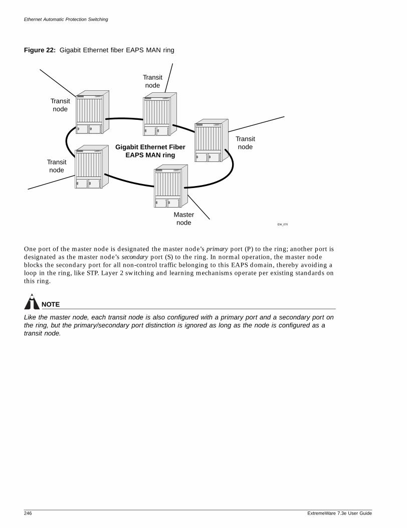
Ethernet Automatic Protection Switching
Figure 22: Gigabit Ethernet fiber EAPS MAN ring
One port of the master node is designated the master node’s primary port (P) to the ring; another port is designated as the master node’s secondary port (S) to the ring. In normal operation, the master node blocks the secondary port for all non-control traffic belonging to this EAPS domain, thereby avoiding a loop in the ring, like STP. Layer 2 switching and learning mechanisms operate per existing standards on this ring.
NOTE
Like the master node, each transit node is also configured with a primary port and a secondary port on the ring, but the primary/secondary port distinction is ignored as long as the node is configured as a transit node.
EW_070
Gigabit Ethernet FiberEAPS MAN ring
Masternode
Transitnode
Transitnode
Transitnode
Transitnode
246 ExtremeWare 7.3e User Guide
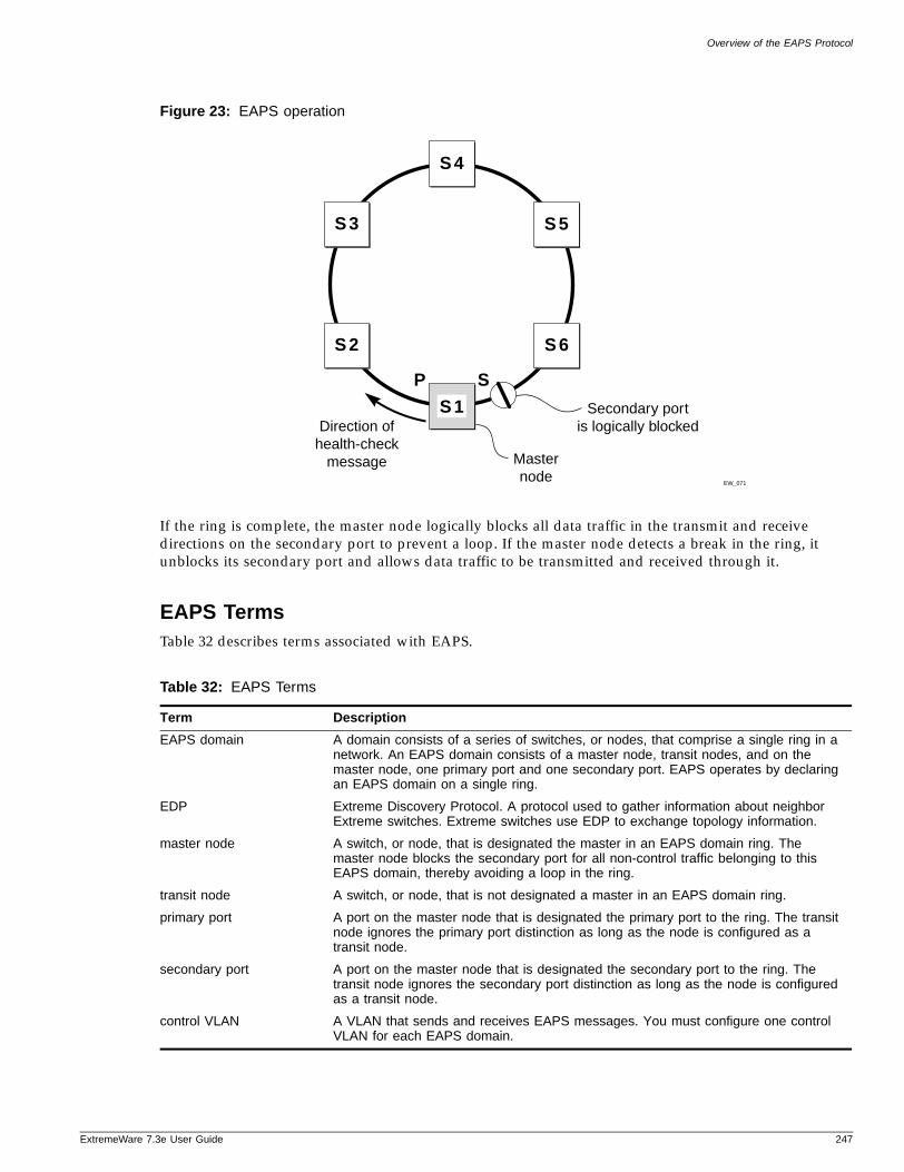
Overview of the EAPS Protocol
ExtremeWare 7
Figure 23: EAPS operation
If the ring is complete, the master node logically blocks all data traffic in the transmit and receive directions on the secondary port to prevent a loop. If the master node detects a break in the ring, it unblocks its secondary port and allows data traffic to be transmitted and received through it.
EAPS TermsTable 32 describes terms associated with EAPS.
Table 32: EAPS Terms
Term Description
EAPS domain A domain consists of a series of switches, or nodes, that comprise a single ring in a network. An EAPS domain consists of a master node, transit nodes, and on the master node, one primary port and one secondary port. EAPS operates by declaring an EAPS domain on a single ring.
EDP Extreme Discovery Protocol. A protocol used to gather information about neighbor Extreme switches. Extreme switches use EDP to exchange topology information.
master node A switch, or node, that is designated the master in an EAPS domain ring. The master node blocks the secondary port for all non-control traffic belonging to this EAPS domain, thereby avoiding a loop in the ring.
transit node A switch, or node, that is not designated a master in an EAPS domain ring.
primary port A port on the master node that is designated the primary port to the ring. The transit node ignores the primary port distinction as long as the node is configured as a transit node.
secondary port A port on the master node that is designated the secondary port to the ring. The transit node ignores the secondary port distinction as long as the node is configured as a transit node.
control VLAN A VLAN that sends and receives EAPS messages. You must configure one control VLAN for each EAPS domain.
EW_071
Direction ofhealth-check
message Masternode
Secondary portis logically blocked
S 4
S 5
S 6
S 3
S 2
S 1
SP
.3e User Guide 247
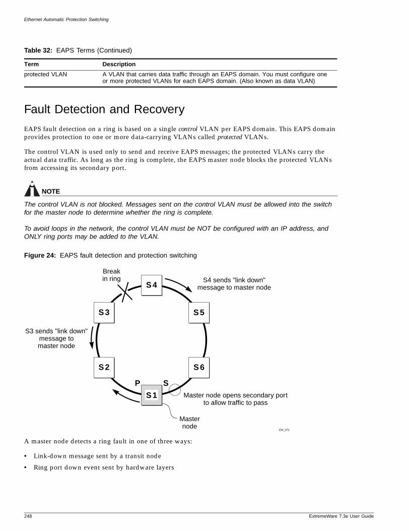
Ethernet Automatic Protection Switching
Fault Detection and Recovery
EAPS fault detection on a ring is based on a single control VLAN per EAPS domain. This EAPS domain provides protection to one or more data-carrying VLANs called protected VLANs.
The control VLAN is used only to send and receive EAPS messages; the protected VLANs carry the actual data traffic. As long as the ring is complete, the EAPS master node blocks the protected VLANs from accessing its secondary port.
NOTE
The control VLAN is not blocked. Messages sent on the control VLAN must be allowed into the switch for the master node to determine whether the ring is complete.
To avoid loops in the network, the control VLAN must be NOT be configured with an IP address, and ONLY ring ports may be added to the VLAN.
Figure 24: EAPS fault detection and protection switching
A master node detects a ring fault in one of three ways:
• Link-down message sent by a transit node
• Ring port down event sent by hardware layers
protected VLAN A VLAN that carries data traffic through an EAPS domain. You must configure one or more protected VLANs for each EAPS domain. (Also known as data VLAN)
Table 32: EAPS Terms (Continued)
Term Description
EW_072
S3 sends "link down"message tomaster node
Masternode
Breakin ring
Master node opens secondary portto allow traffic to pass
S4 sends "link down"message to master nodeS 4
S 5
S 6
S 3
S 2
S 1
P S
248 ExtremeWare 7.3e User Guide
Fault Detection and Recovery
ExtremeWare 7
• Polling response
Link Down Message Sent by a Transit NodeWhen any transit node detects a loss of link connectivity on any of its ring ports, it immediately sends a “link down” message on the control VLAN using its good link to the master node.
When the master node receives the “link down” message (see Figure 24), it immediately declares a “failed” state and opens its logically blocked secondary port on all the protected VLANs. Now, traffic can flow through the master’s secondary port. The master node also flushes its FDB and sends a message on the control VLAN to all of its associated transit nodes to flush their forwarding databases as well, so that all of the switches can learn the new paths to layer 2 end stations on the reconfigured ring topology.
Ring Port Down Event Sent by Hardware LayerWhen a ring port goes down on a master node switch, it is notified by the lower hardware layer and immediately goes into a “failed” state.
If the primary ring port goes down, the secondary port is opened. The normal operation of flushing its FDB and sending a “link-down” message to all transit nodes is performed.
PollingThe master node transmits a health-check packet on the control VLAN at a user-configurable interval (see Figure 23). If the ring is complete, the master node will receive the health-check packet on its secondary port (the control VLAN is not blocked on the secondary port). When the master node receives the health-check packet, it resets its failtimer and continues normal operation.
If the master node does not receive the health-check packet before the failtimer interval expires, and the failtime expiry action is set to open the secondary port when the failtimer expires, it declares a “failed” state. The switch then performs the same steps described above: it unblocks its secondary port for access by the protected VLANs, flushes its forwarding database (FDB), and sends a “flush FDB” message to its associated transit nodes.
To change the expiry timer action, use the following command:
configure eaps <name> failtime expiry-action [ open-secondary-port | send-alert]
To change the duration of the failtime, use the following command:
configure eaps <name> failtime [<seconds>]
Restoration OperationsThe master node continues sending health-check packets out its primary port even when the master node is operating in the failed state. As long as there is a break in the ring, the fail-period timer of the master node will continue to expire and the master node will remain in the failed state.
When the broken link is restored, the master will receive its health-check packet back on its secondary port, and will once again declare the ring to be complete. It will logically block the protected VLANs on its secondary port, flush its FDB, and send a “flush FDB” message to its associated transit nodes.
.3e User Guide 249
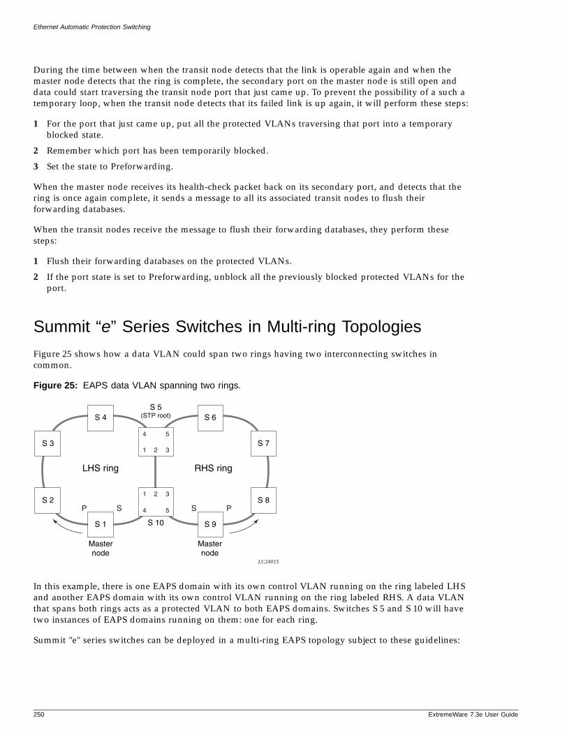
Ethernet Automatic Protection Switching
During the time between when the transit node detects that the link is operable again and when the master node detects that the ring is complete, the secondary port on the master node is still open and data could start traversing the transit node port that just came up. To prevent the possibility of a such a temporary loop, when the transit node detects that its failed link is up again, it will perform these steps:
1 For the port that just came up, put all the protected VLANs traversing that port into a temporary blocked state.
2 Remember which port has been temporarily blocked.
3 Set the state to Preforwarding.
When the master node receives its health-check packet back on its secondary port, and detects that the ring is once again complete, it sends a message to all its associated transit nodes to flush their forwarding databases.
When the transit nodes receive the message to flush their forwarding databases, they perform these steps:
1 Flush their forwarding databases on the protected VLANs.
2 If the port state is set to Preforwarding, unblock all the previously blocked protected VLANs for the port.
Summit “e” Series Switches in Multi-ring Topologies
Figure 25 shows how a data VLAN could span two rings having two interconnecting switches in common.
Figure 25: EAPS data VLAN spanning two rings.
In this example, there is one EAPS domain with its own control VLAN running on the ring labeled LHS and another EAPS domain with its own control VLAN running on the ring labeled RHS. A data VLAN that spans both rings acts as a protected VLAN to both EAPS domains. Switches S 5 and S 10 will have two instances of EAPS domains running on them: one for each ring.
Summit "e" series switches can be deployed in a multi-ring EAPS topology subject to these guidelines:
LC24015
S 4
S 3
S 2
S 7
S 8
S 6S 5
(STP root)
S 10S 1
Masternode
Masternode
S 9
LHS ring RHS ring
P S S P
1 2 3
1 2 3
4 5
4 5
250 ExtremeWare 7.3e User Guide
Configuring EAPS on a Switch
ExtremeWare 7
• Summit "e" series switches can be used as any of the EAPS nodes in the ring except as a node that interconnects the two rings. For example, in the example shown in Figure 25, nodes S 5 and S 10 cannot be Summit "e" series switches. Summit "e" series switches support EAPS Version 1 (EAPSv1) and only support a single EAPS domain per switch.
• Depending on the network topology and the versions of EAPS (EAPSv1 vs. EAPSv2) running on the other EAPS nodes, there might be a requirement to configure STP support for EAPSv1 to prevent super loops—in the event of a break in the common link between the nodes interconnecting the rings. On multi-ring topologies, the node interconnecting two rings either needs to be running EAPSv2 or it must be configured for STP. By having either EAPSv2 or STP on this connecting node, the Summit 200 has EAPS awareness and correctly recovers in the event of a break in the common link. For example, in the example shown in Figure 25, a break in the link between nodes S 5 and S 10 would result in a super loop if they were both running EAPSv1 without STP. The following scenarios demonstrate the different EAPS configurations.
— Case 1: Summit "e" series switches on a single ring. In this case, EAPSv1 requires no STP support because it is not interconnecting with another ring.
— Case 2: Summit "e" series switches on a multi-ring network along with ring-connecting switches not running EAPSv2. In this case, the Summit "e" series switches still cannot be ring-connecting nodes, and this implementation requires configuring EAPSv1 plus STP support to prevent super loops. This configuration process is described in the EAPS chapter of the ExtremeWare Software User Guide, Version 7.1.0.
— Case 3: Summit "e" series switches on a multi-ring network along with ring-connecting switches running EAPSv2. In this case, the Summit "e" series switches still cannot be ring-connecting nodes. However, having EAPSv2 running on the node that interconnects the rings will prevent problems with super-loops without requiring STP. This configuration process is described in the EAPS chapter of the ExtremeWare Software User Guide, Version 7.1.0.
Configuring EAPS on a Switch
This section describes how to configure EAPS on a switch.
Creating and Deleting an EAPS DomainEach EAPS domain is identified by a unique domain name.
NOTE
Only a single EAPS domain per switch is supported by Summit "e" series switches.
To create an EAPS domain, use the following command:
create eaps <name>
The name parameter is a character string of up to 32 characters that identifies the EAPS domain to be created. EAPS domain names and VLAN names must be unique: Do not use the same name string to identify both an EAPS domain and a VLAN.
The following command example creates an EAPS domain named “eaps_1”:
create eaps eaps_1
.3e User Guide 251
Ethernet Automatic Protection Switching
To delete an EAPS domain, use the following command:
delete eaps <name>
The following command example deletes the EAPS domain “eaps_1”:
delete eaps eaps_1
Defining the EAPS Mode of the SwitchTo configure the EAPS node type of the switch, use the following command:
configure eaps <name> mode [master | transit]
One node on the ring must be configured as the master node for the specified domain; all other nodes on the ring are configured as transit nodes for the same domain.
The following command example identifies this switch as the master node for the EAPS domain named eaps_1.
configure eaps eaps_1 mode master
The following command example identifies this switch as a transit node for the EAPS domain named eaps_1.
configure eaps eaps_1 mode transit
Configuring EAPS Polling TimersTo set the values of the polling timers the master node uses for the EAPS health-check packet that is circulated around the ring for an EAPS domain, use the following command:
configure eaps <name> hellotime <seconds>configure eaps <name> failtime [<seconds>]
To configure the action taken if there is a break in the ring, use the following command:
configure eaps <name> failtime expiry-action [ open-secondary-port | send-alert]
NOTE
These commands apply only to the master node. If you configure the polling timers for a transit node, they will be ignored. If you later reconfigure that transit node as the master node, the polling timer values will be used as the current values.
Use the hellotime keyword and its associated seconds parameter to specify the amount of time the master node waits between transmissions of health-check packets on the control VLAN. seconds must be greater than 0 when you are configuring a master node. The default value is one second.
NOTE
Increasing the hellotime value keeps the processor from sending and processing too many health-check packets. Increasing the hellotime value should not affect the network convergence time, because transit nodes are already sending “link down” notifications.
252 ExtremeWare 7.3e User Guide
Configuring EAPS on a Switch
ExtremeWare 7
Use the failtime keyword and seconds parameters to specify the amount of time the master node waits before the failtimer expires.
The seconds parameter must be greater than the configured value for hellotime. The default value is three seconds.
You can configure the action taken when the failtimer expires by using the configure eaps failtime expiry-action command. Use the send-alert parameter to send an alert when the failtimer expires. Instead of going into a “failed” state, the master node remains in a “Complete” or “Init” state, maintains the secondary port blocking, and writes a critical error message to syslog warning the user that there is a fault in the ring. An SNMP trap is also sent.
To use the failtimer expiry action of earlier releases, use the open-secondary-port parameter.
NOTE
Increasing the failtime value provides more protection by waiting longer to receive a health-check packet when the network is congested.
The following command examples configure the hellotime value for the EAPS domain “eaps_1” to 2 seconds, the failtime value to 15 seconds, and the failtime expiry-action to open the secondary port if the failtimer expires:
configure eaps eaps_1 hellotime 2configure eaps eaps_1 failtime 15configure eaps eaps_1 failtimer expiry-action open-secondary-port
Configuring the Primary and Secondary PortsEach node on the ring connects to the ring through two ring ports. As part of the protection switching scheme, one port must be configured as the primary port; the other must be configured as the secondary port.
If the ring is complete, the master node prevents a loop by logically blocking all data traffic in the transmit and receive directions on its secondary port. If the master node subsequently detects a break in the ring, it unblocks its secondary port and allows data traffic to be transmitted and received through it.
To configure a node port as primary or secondary, use the following command:
configure eaps <name> [primary | secondary] port <port number>
The following command example adds port 1 of the switch to the EAPS domain “eaps_1” as the primary port.
configure eaps eaps_1 primary port 1
Configuring the EAPS Control VLANYou must configure one control VLAN for each EAPS domain. The control VLAN is used only to send and receive EAPS messages.
.3e User Guide 253
Ethernet Automatic Protection Switching
NOTE
If the domain is active, you cannot delete the domain or modify the configuration of the control VLAN.
To configure the EAPS control VLAN for the domain, use the following command:
configure eaps <name> add control vlan <vlan_name>
NOTE
The control VLAN must NOT be configured with an IP address. In addition, only ring ports may be added to this control VLAN. No other ports can be members of this VLAN. Failure to observe these restrictions can result in a loop in the network.
NOTE
When you configure the VLAN that will act as the control VLAN, that VLAN must be assigned a QoS profile of Qp8, and the ring ports of the control VLAN must be tagged.
By assigning the control VLAN a QoS profile of Qp8 (with the QoS profile HighHi priority setting), you ensure that EAPS control VLAN traffic is serviced before any other traffic and that control VLAN messages reach their intended destinations. For example, if the control VLAN is not assigned the highest priority and a broadcast storm occurs in the network, the control VLAN messages might be dropped at intermediate points. Assigning the control VLAN the highest priority prevents dropped control VLAN messages.
NOTE
Because the QoS profiles Qp7 and Qp8 share the same hardware queue in the Summit "e" series switch, you must limit the amount of traffic that uses these profiles; otherwise, the Summit "e" series switch may drop EAPS control packets, preventing EAPS from operating reliably.
Because the QoS profile High priority setting by itself should ensure that the control VLAN traffic gets through a congested port first, you should not need to set the QoS profile minimum bandwidth (minbw) or maximum bandwidth (maxbw) settings. However, if you plan to use QoS (profile priority and bandwidth settings) for other traffic, you might need to set a minbw value on Qp8 for control VLAN traffic. Whether you need to do this depends entirely on your configuration.
The following command example adds the control VLAN “keys” to the EAPS domain “eaps_1”.
configure eaps eaps_1 add control vlan keys
Configuring the EAPS Protected VLANsYou must configure one or more protected VLANs for each EAPS domain. The protected VLANs are the data-carrying VLANs.
NOTE
When you configure the VLAN that will act as a protected VLAN, the ring ports of the protected VLAN must be tagged (except in the case of the default VLAN).
254 ExtremeWare 7.3e User Guide
Configuring EAPS on a Switch
ExtremeWare 7
To configure an EAPS protected VLAN, use the following command:
configure eaps <name> add protect vlan <vlan_name>
NOTE
As long as the ring is complete, the master node blocks the protected VLANs on its secondary port.
The following command example adds the protected VLAN “orchid” to the EAPS domain “eaps_1.”
configure eaps eaps_1 add protect vlan orchid
NOTE
The configuration of the Superbridge, SubBridge, and IP range control VLANs cannot be modified.
Enabling and Disabling an EAPS DomainTo enable a specific EAPS domain, use the following command:
enable eaps {<name>}
To disable a specific EAPS domain, use the following command:
disable eaps {<name>}
Enabling and Disabling EAPSTo enable the EAPS function for the entire switch, use the following command:
enable eaps
To disable the EAPS function for the entire switch, use the following command:
disable eaps
Unconfiguring an EAPS Ring PortUnconfiguring an EAPS port sets its internal configuration state to INVALID, which causes the port to appear in the Idle state with a port status of Unknown when you use the show eaps {<name>} {detail} command to display the status information about the port.
To unconfigure an EAPS primary or secondary ring port for an EAPS domain, use the following command:
unconfigure eaps <name> [primary | secondary] port
The following command example unconfigures this node’s EAPS primary ring port on the domain “eaps_1”:
unconfigure eaps eaps_1 primary port
Displaying EAPS Status InformationTo display EAPS status information, use the following command:
show eaps summary
.3e User Guide 255
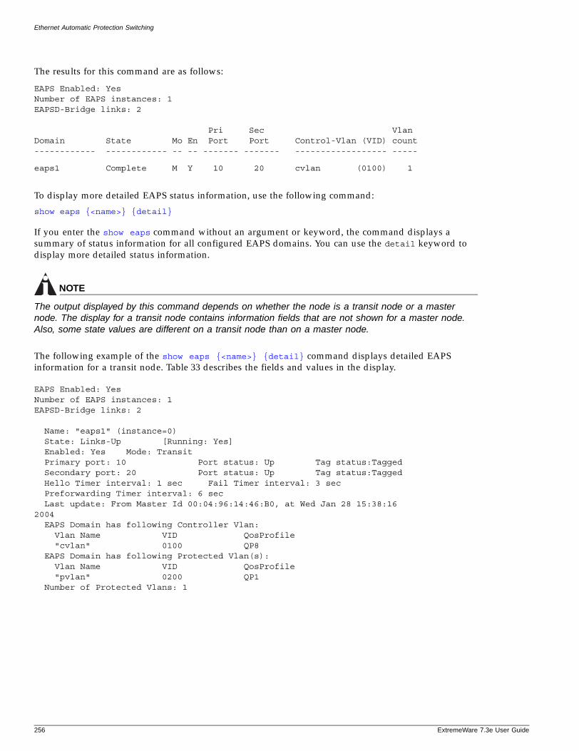
Ethernet Automatic Protection Switching
The results for this command are as follows:
EAPS Enabled: YesNumber of EAPS instances: 1EAPSD-Bridge links: 2
Pri Sec VlanDomain State Mo En Port Port Control-Vlan (VID) count------------ ------------ -- -- ------- ------- ------------------ -----
eaps1 Complete M Y 10 20 cvlan (0100) 1
To display more detailed EAPS status information, use the following command:
show eaps {<name>} {detail}
If you enter the show eaps command without an argument or keyword, the command displays a summary of status information for all configured EAPS domains. You can use the detail keyword to display more detailed status information.
NOTE
The output displayed by this command depends on whether the node is a transit node or a master node. The display for a transit node contains information fields that are not shown for a master node. Also, some state values are different on a transit node than on a master node.
The following example of the show eaps {<name>} {detail} command displays detailed EAPS information for a transit node. Table 33 describes the fields and values in the display.
EAPS Enabled: YesNumber of EAPS instances: 1EAPSD-Bridge links: 2
Name: "eaps1" (instance=0) State: Links-Up [Running: Yes] Enabled: Yes Mode: Transit Primary port: 10 Port status: Up Tag status:Tagged Secondary port: 20 Port status: Up Tag status:Tagged Hello Timer interval: 1 sec Fail Timer interval: 3 sec Preforwarding Timer interval: 6 sec Last update: From Master Id 00:04:96:14:46:B0, at Wed Jan 28 15:38:162004 EAPS Domain has following Controller Vlan: Vlan Name VID QosProfile "cvlan" 0100 QP8 EAPS Domain has following Protected Vlan(s): Vlan Name VID QosProfile "pvlan" 0200 QP1 Number of Protected Vlans: 1
256 ExtremeWare 7.3e User Guide
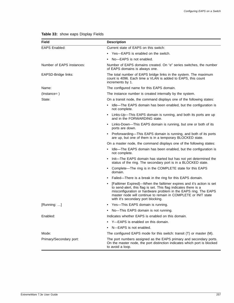
Configuring EAPS on a Switch
ExtremeWare 7
Table 33: show eaps Display Fields
Field Description
EAPS Enabled: Current state of EAPS on this switch:
• Yes—EAPS is enabled on the switch.
• No—EAPS is not enabled.
Number of EAPS instances: Number of EAPS domains created. On “e” series switches, the number of EAPS domains is always one.
EAPSD-Bridge links: The total number of EAPS bridge links in the system. The maximum count is 4096. Each time a VLAN is added to EAPS, this count increments by 1.
Name: The configured name for this EAPS domain.
(Instance= ) The instance number is created internally by the system.
State: On a transit node, the command displays one of the following states:
• Idle—The EAPS domain has been enabled, but the configuration is not complete.
• Links-Up—This EAPS domain is running, and both its ports are up and in the FORWARDING state.
• Links-Down—This EAPS domain is running, but one or both of its ports are down.
• Preforwarding—This EAPS domain is running, and both of its ports are up, but one of them is in a temporary BLOCKED state.
On a master node, the command displays one of the following states:
• Idle—The EAPS domain has been enabled, but the configuration is not complete.
• Init—The EAPS domain has started but has not yet determined the status of the ring. The secondary port is in a BLOCKED state.
• Complete—The ring is in the COMPLETE state for this EAPS domain.
• Failed—There is a break in the ring for this EAPS domain.
• [Failtimer Expired]—When the failtimer expires and it’s action is set to send-alert, this flag is set. This flag indicates there is a misconfiguration or hardware problem in the EAPS ring. The EAPS master node will continue to remain in COMPLETE or INIT state with it’s secondary port blocking.
[Running: …] • Yes—This EAPS domain is running.
• No—This EAPS domain is not running.
Enabled: Indicates whether EAPS is enabled on this domain.
• Y—EAPS is enabled on this domain.
• N—EAPS is not enabled.
Mode: The configured EAPS mode for this switch: transit (T) or master (M).
Primary/Secondary port: The port numbers assigned as the EAPS primary and secondary ports. On the master node, the port distinction indicates which port is blocked to avoid a loop.
.3e User Guide 257
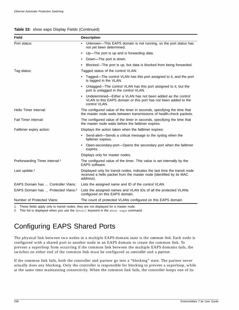
Ethernet Automatic Protection Switching
Configuring EAPS Shared Ports
The physical link between two nodes in a multiple EAPS domain state is the common link. Each node is configured with a shared port to another node in an EAPS domain to create the common link. To prevent a superloop from occurring if the common link between the multiple EAPS domains fails, the switches on either end of the common link must be configured as controller and a partner.
If the common link fails, both the controller and partner go into a “blocking” state. The partner never actually does any blocking. Only the controller is responsible for blocking to prevent a superloop, while at the same time maintaining connectivity. When the common link fails, the controller keeps one of its
Port status: • Unknown—This EAPS domain is not running, so the port status has not yet been determined.
• Up—The port is up and is forwarding data.
• Down—The port is down.
• Blocked—The port is up, but data is blocked from being forwarded.
Tag status: Tagged status of the control VLAN:
• Tagged—The control VLAN has this port assigned to it, and the port is tagged in the VLAN.
• Untagged—The control VLAN has this port assigned to it, but the port is untagged in the control VLAN.
• Undetermined—Either a VLAN has not been added as the control VLAN to this EAPS domain or this port has not been added to the control VLAN.
Hello Timer interval: The configured value of the timer in seconds, specifying the time that the master node waits between transmissions of health-check packets.
Fail Timer interval: The configured value of the timer in seconds, specifying the time that the master node waits before the failtimer expires.
Failtimer expiry action: Displays the action taken when the failtimer expires:
• Send-alert—Sends a critical message to the syslog when the failtimer expires.
• Open-secondary-port—Opens the secondary port when the failtimer expires.
Displays only for master nodes.
Preforwarding Timer interval:1 The configured value of the timer. This value is set internally by the EAPS software.
Last update:1 Displayed only for transit nodes; indicates the last time the transit node received a hello packet from the master node (identified by its MAC address).
EAPS Domain has … Controller Vlans: Lists the assigned name and ID of the control VLAN.
EAPS Domain has … Protected Vlans:2 Lists the assigned names and VLAN IDs of all the protected VLANs configured on this EAPS domain.
Number of Protected Vlans: The count of protected VLANs configured on this EAPS domain.
1. These fields apply only to transit nodes; they are not displayed for a master node.2. This list is displayed when you use the detail keyword in the show eaps command.
Table 33: show eaps Display Fields (Continued)
Field Description
258 ExtremeWare 7.3e User Guide
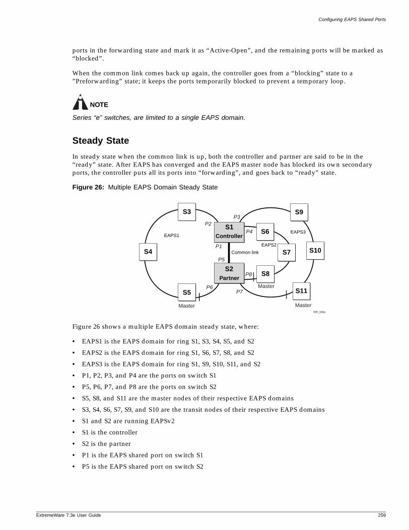
Configuring EAPS Shared Ports
ExtremeWare 7
ports in the forwarding state and mark it as “Active-Open”, and the remaining ports will be marked as “blocked”.
When the common link comes back up again, the controller goes from a “blocking” state to a ”Preforwarding” state; it keeps the ports temporarily blocked to prevent a temporary loop.
NOTE
Series “e” switches, are limited to a single EAPS domain.
Steady State
In steady state when the common link is up, both the controller and partner are said to be in the “ready” state. After EAPS has converged and the EAPS master node has blocked its own secondary ports, the controller puts all its ports into “forwarding”, and goes back to “ready” state.
Figure 26: Multiple EAPS Domain Steady State
Figure 26 shows a multiple EAPS domain steady state, where:
• EAPS1 is the EAPS domain for ring S1, S3, S4, S5, and S2
• EAPS2 is the EAPS domain for ring S1, S6, S7, S8, and S2
• EAPS3 is the EAPS domain for ring S1, S9, S10, S11, and S2
• P1, P2, P3, and P4 are the ports on switch S1
• P5, P6, P7, and P8 are the ports on switch S2
• S5, S8, and S11 are the master nodes of their respective EAPS domains
• S3, S4, S6, S7, S9, and S10 are the transit nodes of their respective EAPS domains
• S1 and S2 are running EAPSv2
• S1 is the controller
• S2 is the partner
• P1 is the EAPS shared port on switch S1
• P5 is the EAPS shared port on switch S2
EW_102a
S4
S5
S3
EAPS1
Partner
S9
S11
S10
S1
S2
EAPS2
EAPS3Controller
S6
S8
S7
Master
Master
Master
P1
P2P3
P4
P5
P6P7
P8
Common link
.3e User Guide 259
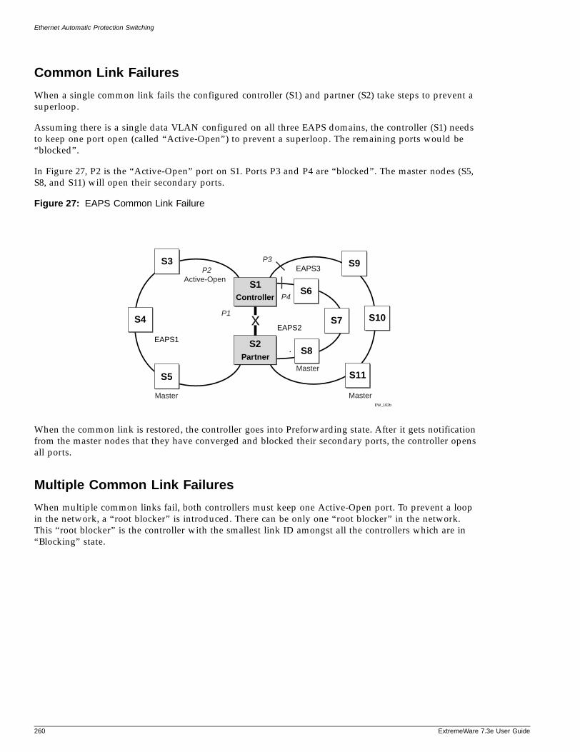
Ethernet Automatic Protection Switching
Common Link Failures
When a single common link fails the configured controller (S1) and partner (S2) take steps to prevent a superloop.
Assuming there is a single data VLAN configured on all three EAPS domains, the controller (S1) needs to keep one port open (called “Active-Open”) to prevent a superloop. The remaining ports would be “blocked”.
In Figure 27, P2 is the “Active-Open” port on S1. Ports P3 and P4 are “blocked”. The master nodes (S5, S8, and S11) will open their secondary ports.
Figure 27: EAPS Common Link Failure
When the common link is restored, the controller goes into Preforwarding state. After it gets notification from the master nodes that they have converged and blocked their secondary ports, the controller opens all ports.
Multiple Common Link Failures
When multiple common links fail, both controllers must keep one Active-Open port. To prevent a loop in the network, a “root blocker” is introduced. There can be only one “root blocker” in the network. This “root blocker” is the controller with the smallest link ID amongst all the controllers which are in “Blocking” state.
EW_102b
S4
S5
S3
EAPS1
Partner
S9
S11
S10
S1
S2
EAPS2
EAPS3
ControllerS6
S8
S7
Master
Master
Master
P1
P2P3
P4
x
Active-Open
260 ExtremeWare 7.3e User Guide
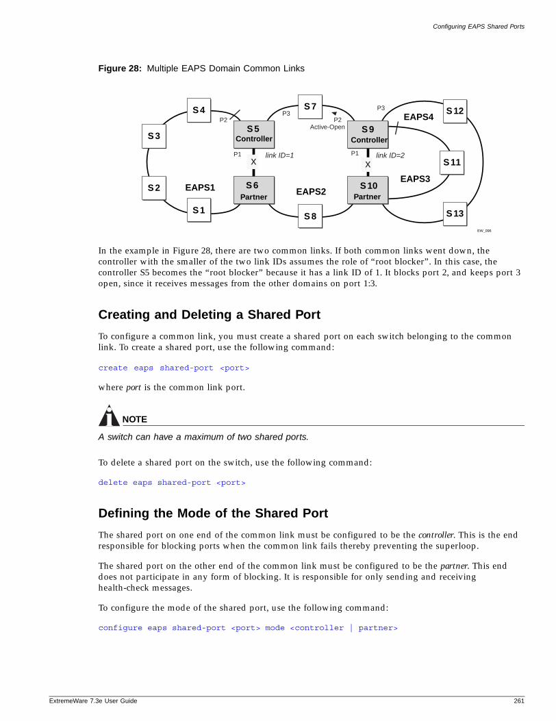
Configuring EAPS Shared Ports
ExtremeWare 7
Figure 28: Multiple EAPS Domain Common Links
In the example in Figure 28, there are two common links. If both common links went down, the controller with the smaller of the two link IDs assumes the role of “root blocker”. In this case, the controller S5 becomes the “root blocker” because it has a link ID of 1. It blocks port 2, and keeps port 3 open, since it receives messages from the other domains on port 1:3.
Creating and Deleting a Shared Port
To configure a common link, you must create a shared port on each switch belonging to the common link. To create a shared port, use the following command:
create eaps shared-port <port>
where port is the common link port.
NOTE
A switch can have a maximum of two shared ports.
To delete a shared port on the switch, use the following command:
delete eaps shared-port <port>
Defining the Mode of the Shared PortThe shared port on one end of the common link must be configured to be the controller. This is the end responsible for blocking ports when the common link fails thereby preventing the superloop.
The shared port on the other end of the common link must be configured to be the partner. This end does not participate in any form of blocking. It is responsible for only sending and receiving health-check messages.
To configure the mode of the shared port, use the following command:
configure eaps shared-port <port> mode <controller | partner>
EW_096
S 4
S 3
S 2
S 1
PartnerEAPS1
S 8
S 7
S 5
S 6EAPS2
Controller
Partner
S 12
S 13
S 11
S 9
S 10EAPS3
EAPS4
Controller
link ID=1 link ID=2P1 P1
P2
P3P3
x x
Active-OpenP2
.3e User Guide 261
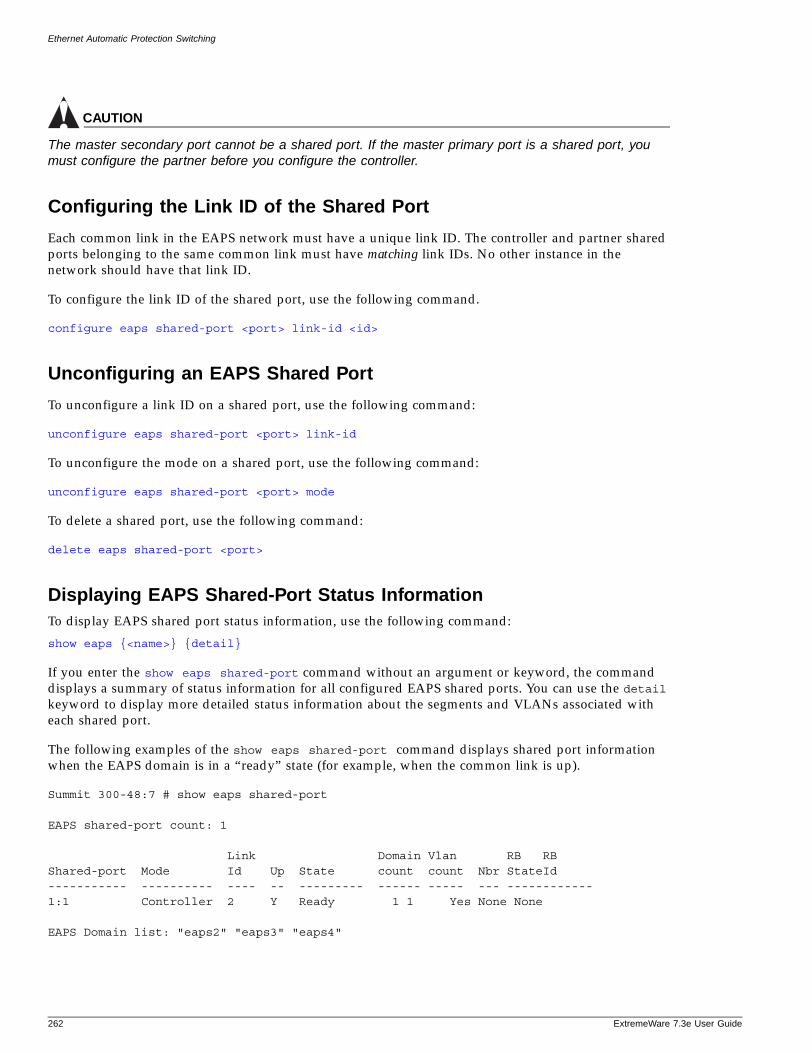
Ethernet Automatic Protection Switching
CAUTION
The master secondary port cannot be a shared port. If the master primary port is a shared port, you must configure the partner before you configure the controller.
Configuring the Link ID of the Shared PortEach common link in the EAPS network must have a unique link ID. The controller and partner shared ports belonging to the same common link must have matching link IDs. No other instance in the network should have that link ID.
To configure the link ID of the shared port, use the following command.
configure eaps shared-port <port> link-id <id>
Unconfiguring an EAPS Shared Port
To unconfigure a link ID on a shared port, use the following command:
unconfigure eaps shared-port <port> link-id
To unconfigure the mode on a shared port, use the following command:
unconfigure eaps shared-port <port> mode
To delete a shared port, use the following command:
delete eaps shared-port <port>
Displaying EAPS Shared-Port Status InformationTo display EAPS shared port status information, use the following command:
show eaps {<name>} {detail}
If you enter the show eaps shared-port command without an argument or keyword, the command displays a summary of status information for all configured EAPS shared ports. You can use the detail keyword to display more detailed status information about the segments and VLANs associated with each shared port.
The following examples of the show eaps shared-port command displays shared port information when the EAPS domain is in a “ready” state (for example, when the common link is up).
Summit 300-48:7 # show eaps shared-port
EAPS shared-port count: 1
Link Domain Vlan RB RB Shared-port Mode Id Up State count count Nbr StateId ----------- ---------- ---- -- --------- ------ ----- --- ------------1:1 Controller 2 Y Ready 1 1 Yes None None
EAPS Domain list: "eaps2" "eaps3" "eaps4"
262 ExtremeWare 7.3e User Guide
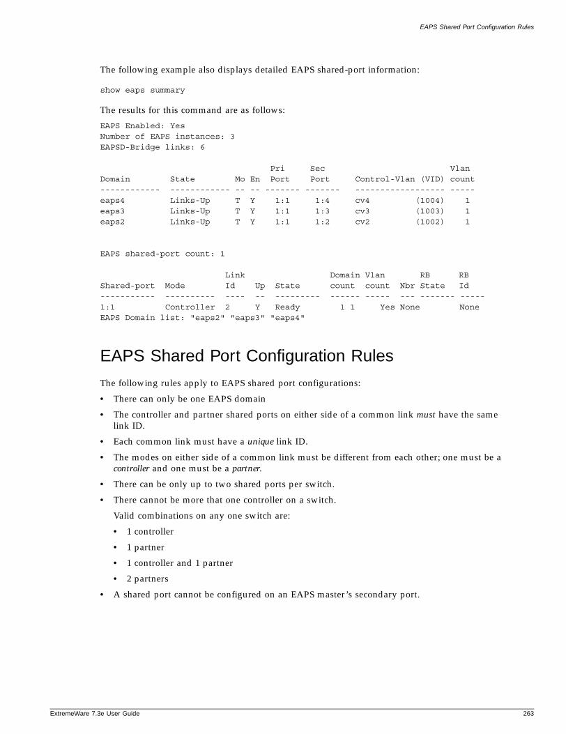
EAPS Shared Port Configuration Rules
ExtremeWare 7
The following example also displays detailed EAPS shared-port information:
show eaps summary
The results for this command are as follows:
EAPS Enabled: YesNumber of EAPS instances: 3EAPSD-Bridge links: 6
Pri Sec VlanDomain State Mo En Port Port Control-Vlan (VID) count ------------ ------------ -- -- ------- ------- ------------------ ----- eaps4 Links-Up T Y 1:1 1:4 cv4 (1004) 1eaps3 Links-Up T Y 1:1 1:3 cv3 (1003) 1eaps2 Links-Up T Y 1:1 1:2 cv2 (1002) 1
EAPS shared-port count: 1
Link Domain Vlan RB RB Shared-port Mode Id Up State count count Nbr State Id ----------- ---------- ---- -- --------- ------ ----- --- ------- -----1:1 Controller 2 Y Ready 1 1 Yes None None EAPS Domain list: "eaps2" "eaps3" "eaps4"
EAPS Shared Port Configuration Rules
The following rules apply to EAPS shared port configurations:
• There can only be one EAPS domain
• The controller and partner shared ports on either side of a common link must have the same link ID.
• Each common link must have a unique link ID.
• The modes on either side of a common link must be different from each other; one must be a controller and one must be a partner.
• There can be only up to two shared ports per switch.
• There cannot be more that one controller on a switch.
Valid combinations on any one switch are:
• 1 controller
• 1 partner
• 1 controller and 1 partner
• 2 partners
• A shared port cannot be configured on an EAPS master’s secondary port.
.3e User Guide 263

Ethernet Automatic Protection Switching
264 ExtremeWare 7.3e User Guide
14 Spanning Tree Protocol (STP)
ExtremeWare 7
This chapter covers the following topics:
• Overview of the Spanning Tree Protocol on page 265
• Spanning Tree Domains on page 266
• STP Configurations on page 268
• Rapid Spanning Tree Protocol on page 271
• STP Rules and Restrictions on page 281
• Configuring STP on the Switch on page 281
• Displaying STP Settings on page 283
Using the Spanning Tree Protocol (STP) functionality of the switch makes your network more fault tolerant. The following sections explain more about STP and the STP features supported by ExtremeWare.
NOTE
STP is a part of the 802.1d bridge specification defined by the IEEE Computer Society. To explain STP in terms used by the 802.1d specification, the switch will be referred to as a bridge.
Overview of the Spanning Tree Protocol
STP is a bridge-based mechanism for providing fault tolerance on networks. STP allows you to implement parallel paths for network traffic, and ensure that:
• Redundant paths are disabled when the main paths are operational.
• Redundant paths are enabled if the main path fails.
NOTE
STP is not supported in conjunction with ESRP.
.3e User Guide 269
Spanning Tree Protocol (STP)
Spanning Tree Domains
The switch can be partitioned into multiple virtual bridges. Each virtual bridge can run an independent Spanning Tree instance. Each Spanning Tree instance is called a Spanning Tree Domain (STPD). Each STPD has its own root bridge and active path. After an STPD is created, one or more VLANs can be assigned to it.
The key points to remember when configuring VLANs and STP are:
• Each VLAN forms an independent broadcast domain.
• STP blocks paths to create a loop-free environment.
• When STP blocks a path, no data can be transmitted or received on the blocked port.
• Within any given STPD, all VLANs belonging to it use the same spanning tree.
If you delete a STPD, the VLANs that were members of that STPD are also deleted. You must remove all VLANs associated with the STP before deleting the STPD to preserve the VLAN configuration.
Ensure that multiple STPD instances within a single switch do not see each other in the same broadcast domain. This could happen if, for example, another external bridge is used to connect VLANs belonging to separate STPDs.
A VLAN can span multiple STPDs. However, on the series “e” switches, there is a hardware limitation that restricts each physical port to a single STPD. If the port is already a member of an STPD, then that port cannot be in another VLAN that is in a different STPD, or not in a STPD at all.
STPD Modes An STPD has two modes of operation
• 802.1d mode
Use this mode for backward compatibility with previous STP versions and for compatibility with third-party switches using IEEE standard 802.1d. When configured in this mode, all rapid configuration mechanisms are disabled.
• 802.1w mode
Use this mode for compatibility with Rapid Spanning Tree (RSTP). When configured in this mode, all rapid configuration mechanisms are enabled. This mode is available for point-to-point links only.
RSTP is enabled or disabled on a per STPD basis only. You do not enable RSTP on a per port basis.
For more information about RSTP and RSTP features, see “Rapid Spanning Tree Protocol” on page 271.
By default, the:
• STPD operates in 802.1d mode
• Default device configuration contains a single STPD called s0
• Default VLAN is a member of STPD s0
To configure the mode of operation of an STPD, use the following command:
configure stpd <spanning tree name> mode [dot1d | dot1w]
All STP parameters default to the IEEE 802.1d values, as appropriate.
# ExtremeWare 7.3e User Guide
Running H/F 1
ExtremeWare 7
Port Modes
An STP port has these modes of operation:
• 802.1d mode
This mode is used for backward compatibility with previous STP versions and for compatibility with third-party switches using IEEE standard 802.1d. BPDUs are sent untagged in 1D mode. Because of this, on any given physical interface there can be only one STPD running in 1D mode.
• Limited support for Extreme Multiple Instance Spanning Tree Protocol (EMISTP) mode
Normally EMISTP mode is an extension of STP that allows a physical port to belong to multiple STPDs by assigning the port to multiple VLANs. BPDUs are sent with an 802.1Q tag having an STPD instance Identifier (StpdID) in the VLANid field.
EMISTP is limited to supporting a single EMISTP domain per physical port, called Compatibility Mode. Compatibility mode is supported to allow other switches using the full EMISTP mode to interoperate with the Summit 400.
• Limited support for PVST+ mode
This mode implements PVST+ in compatibility with third-party switches running this version of STP. The STPDs running in this mode have a one-to-one relationship with VLANs, and send and process packets in PVST+ format.
PVST+ is also limited to supporting a single PVST+ domain per physical port, called Compatibility Mode. Compatibility mode is supported to allow other switches using the full PVST+ mode to interoperate with the Summit “e” series switches. These port modes are for STP ports, not for physical ports. The switch restricts each physical port to a single STPD. When a physical port belongs to multiple STPDs, it is associated with multiple STP ports. It is possible for the physical port to run in different modes for different domains to which it belongs.
STPD Identifier
An StpdID is used to identify each STP domain. You assign the StpdID when configuring the domain, and that VLAN cannot belong to another STPD.
An StpdID must be identical to the VLANid of one of the member VLANs in that STP domain.
NOTE
If an STPD contains at least one port not in 1D mode, the STPD must be configured with an StpdID.
Rapid Root Failover
ExtremeWare supports rapid root failover for faster STP failover recovery times in STP 802.1d mode. If the active root port link goes down ExtremeWare recalculates STP and elects a new root port. Rapid root failover allows the new root port to immediately begin forwarding, skipping the standard listening and learning phases. Rapid root failover occurs only when the link goes down, and not when there is any other root port failure, such as missing BPDUs.
The default setting is disabled. To enable rapid root failover, use the following command:
enable stpd <spanning tree name> rapid-root-failover
To display the configuration, use the following command:
.3e User Guide #
Spanning Tree Protocol (STP)
show stpd {<domain>}
STP Configurations
When you assign VLANs to an STPD, pay careful attention to the STP configuration and its effect on the forwarding of VLAN traffic.
This section describes two types of STP configurations:
• Basic STP
• A VLAN that spans multiple STPDs
Basic STP Configuration
This section describes a basic, 802.1D STP configuration. Figure 29 illustrates a network that uses VLAN tagging for trunk connections. The following four VLANs have been defined:
• Sales is defined on switch A, switch B, and switch M.
• Personnel is defined on switch A, switch B, and switch M.
• Manufacturing is defined on switch Y, switch Z, and switch M.
• Engineering is defined on switch Y, switch Z, and switch M.
• Marketing is defined on all switches (switch A, switch B, switch Y, switch Z, and switch M).
Two STPDs are defined:
• STPD1 contains VLANs Sales and Personnel.
• STPD2 contains VLANs Manufacturing and Engineering.
The VLAN Marketing is a member of both STPD1 and STPD2.
# ExtremeWare 7.3e User Guide
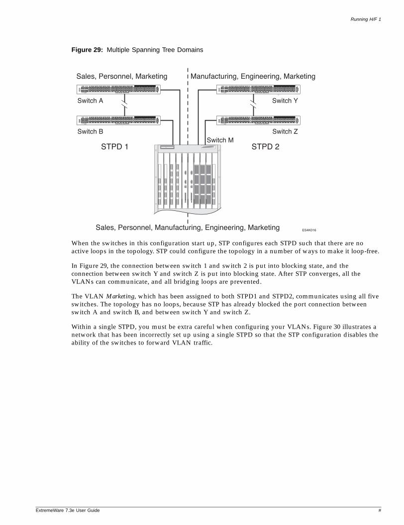
Running H/F 1
ExtremeWare 7
Figure 29: Multiple Spanning Tree Domains
When the switches in this configuration start up, STP configures each STPD such that there are no active loops in the topology. STP could configure the topology in a number of ways to make it loop-free.
In Figure 29, the connection between switch 1 and switch 2 is put into blocking state, and the connection between switch Y and switch Z is put into blocking state. After STP converges, all the VLANs can communicate, and all bridging loops are prevented.
The VLAN Marketing, which has been assigned to both STPD1 and STPD2, communicates using all five switches. The topology has no loops, because STP has already blocked the port connection between switch A and switch B, and between switch Y and switch Z.
Within a single STPD, you must be extra careful when configuring your VLANs. Figure 30 illustrates a network that has been incorrectly set up using a single STPD so that the STP configuration disables the ability of the switches to forward VLAN traffic.
ES4K016
Sales, Personnel, Marketing
STPD 1 STPD 2
Manufacturing, Engineering, Marketing
Sales, Personnel, Manufacturing, Engineering, Marketing
Switch A Switch Y
Switch ZSwitch M
Switch B
.3e User Guide #
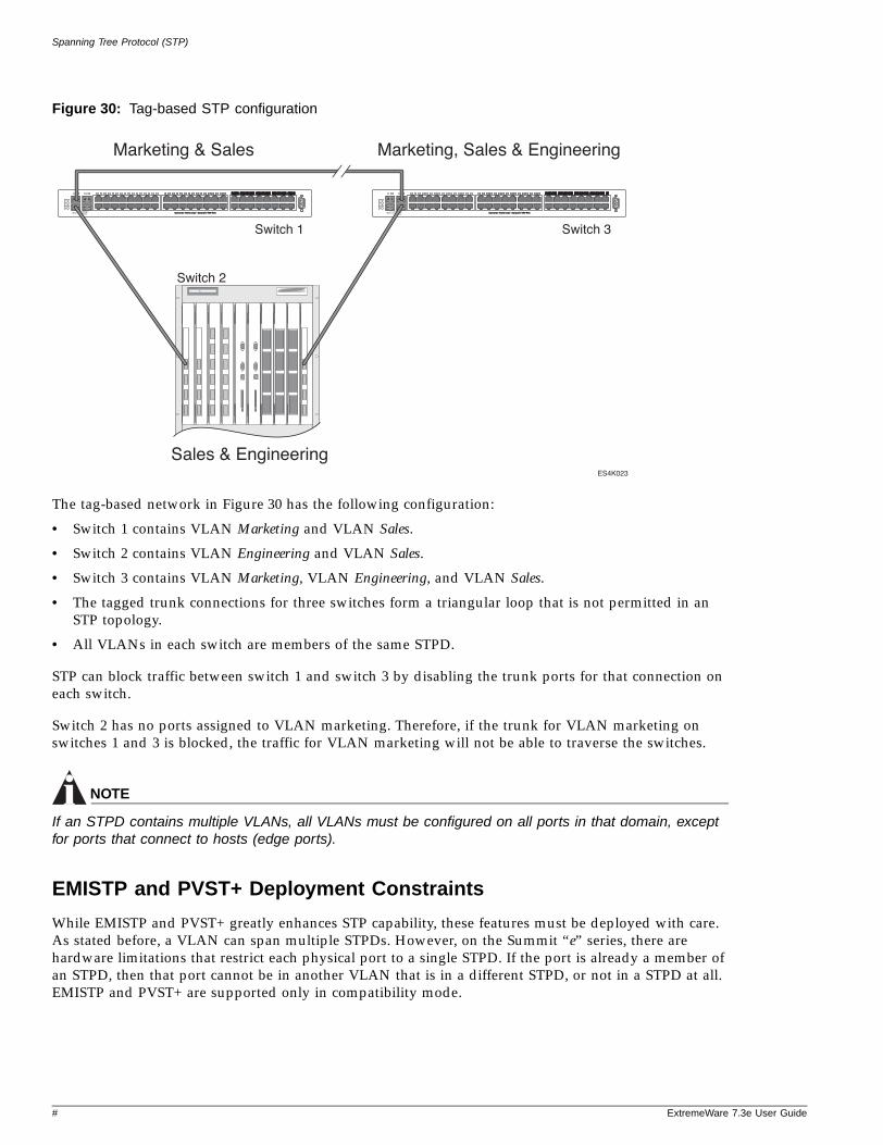
Spanning Tree Protocol (STP)
Figure 30: Tag-based STP configuration
The tag-based network in Figure 30 has the following configuration:
• Switch 1 contains VLAN Marketing and VLAN Sales.
• Switch 2 contains VLAN Engineering and VLAN Sales.
• Switch 3 contains VLAN Marketing, VLAN Engineering, and VLAN Sales.
• The tagged trunk connections for three switches form a triangular loop that is not permitted in an STP topology.
• All VLANs in each switch are members of the same STPD.
STP can block traffic between switch 1 and switch 3 by disabling the trunk ports for that connection on each switch.
Switch 2 has no ports assigned to VLAN marketing. Therefore, if the trunk for VLAN marketing on switches 1 and 3 is blocked, the traffic for VLAN marketing will not be able to traverse the switches.
NOTE
If an STPD contains multiple VLANs, all VLANs must be configured on all ports in that domain, except for ports that connect to hosts (edge ports).
EMISTP and PVST+ Deployment Constraints
While EMISTP and PVST+ greatly enhances STP capability, these features must be deployed with care. As stated before, a VLAN can span multiple STPDs. However, on the Summit “e” series, there are hardware limitations that restrict each physical port to a single STPD. If the port is already a member of an STPD, then that port cannot be in another VLAN that is in a different STPD, or not in a STPD at all. EMISTP and PVST+ are supported only in compatibility mode.
ES4K023
Marketing & Sales Marketing, Sales & Engineering
Switch 1 Switch 3
Switch 2
Sales & Engineering
# ExtremeWare 7.3e User Guide
Running H/F 1
ExtremeWare 7
NOTE
Newly created EMISTP VLANs are not associated with STPD s0 by default.
Per-VLAN Spanning Tree
Switching products that implement Per-VLAN Spanning Tree (PVST) have been in existence for many years and are widely deployed. To support STP configurations that use PVST, ExtremeWare has an operational mode called PVST+. Summit 400 has limited support for PVST+ and only operates in compatibility mode.
Summit “e” series—As stated before, a VLAN can span multiple STPDs. However, on the Summit “e” series, there is a hardware limitation that restricts each physical port to a single STPD. If the switches port is already a member of an STPD, then that port cannot be in another VLAN that is in a different STPD, or not in a STPD at all.
NOTE
In this document, PVST and PVST+ are used interchangeably. PVST+ is an enhanced version of PVST that is interoperable with 802.1Q STP. The following discussions are in regard to PVST+, if not specifically mentioned.
Rapid Spanning Tree Protocol
The Rapid Spanning Tree Protocol (RSTP; 802.1w) provides an enhanced spanning tree algorithm that improves the convergence speed of bridged networks. RSTP takes advantage of point-to-point links in the network and actively confirms that a port can safely transition to the forwarding state without relying on any timer configurations. If a network topology change or failure occurs, RSTP rapidly recovers network connectivity by confirming the change locally before propagating that change to other devices across the network. For broadcast links, there is no difference in convergence time between STP and RSTP.
RSTP supersedes legacy STP protocols, supports the existing STP parameters and configurations, and allows for seamless interoperability with legacy STP.
NOTE
RSTP is not supported in conjunction with ESRP.
RSTP TermsTable 34 describes the terms associated with RSTP.
.3e User Guide #
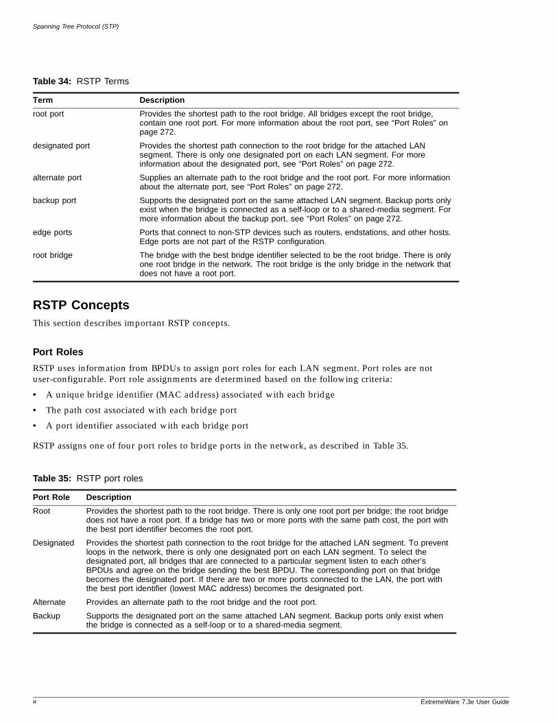
Spanning Tree Protocol (STP)
RSTP ConceptsThis section describes important RSTP concepts.
Port Roles
RSTP uses information from BPDUs to assign port roles for each LAN segment. Port roles are not user-configurable. Port role assignments are determined based on the following criteria:
• A unique bridge identifier (MAC address) associated with each bridge
• The path cost associated with each bridge port
• A port identifier associated with each bridge port
RSTP assigns one of four port roles to bridge ports in the network, as described in Table 35.
Table 34: RSTP Terms
Term Description
root port Provides the shortest path to the root bridge. All bridges except the root bridge, contain one root port. For more information about the root port, see “Port Roles” on page 272.
designated port Provides the shortest path connection to the root bridge for the attached LAN segment. There is only one designated port on each LAN segment. For more information about the designated port, see “Port Roles” on page 272.
alternate port Supplies an alternate path to the root bridge and the root port. For more information about the alternate port, see “Port Roles” on page 272.
backup port Supports the designated port on the same attached LAN segment. Backup ports only exist when the bridge is connected as a self-loop or to a shared-media segment. For more information about the backup port, see “Port Roles” on page 272.
edge ports Ports that connect to non-STP devices such as routers, endstations, and other hosts. Edge ports are not part of the RSTP configuration.
root bridge The bridge with the best bridge identifier selected to be the root bridge. There is only one root bridge in the network. The root bridge is the only bridge in the network that does not have a root port.
Table 35: RSTP port roles
Port Role Description
Root Provides the shortest path to the root bridge. There is only one root port per bridge; the root bridge does not have a root port. If a bridge has two or more ports with the same path cost, the port with the best port identifier becomes the root port.
Designated Provides the shortest path connection to the root bridge for the attached LAN segment. To prevent loops in the network, there is only one designated port on each LAN segment. To select the designated port, all bridges that are connected to a particular segment listen to each other’s BPDUs and agree on the bridge sending the best BPDU. The corresponding port on that bridge becomes the designated port. If there are two or more ports connected to the LAN, the port with the best port identifier (lowest MAC address) becomes the designated port.
Alternate Provides an alternate path to the root bridge and the root port.
Backup Supports the designated port on the same attached LAN segment. Backup ports only exist when the bridge is connected as a self-loop or to a shared-media segment.
# ExtremeWare 7.3e User Guide

Running H/F 1
ExtremeWare 7
When RSTP stabilizes, all:
• Root ports and designated ports are in the forwarding state
• Alternate ports and backup ports are in the blocking state
RSTP makes the distinction between the alternate and backup port roles to describe the rapid transition of the alternate port to the forwarding state if the root port fails.
Ports that connect to non-STP devices are edge ports. Edge ports do not participate in RSTP, and their role is not confirmed. Edge ports immediately enter the forwarding state.
Link Types
You can configure the link type of a port in an STPD. RSTP tries to rapidly move designated point-to-point links into the forwarding state when a network topology change or failure occurs. For rapid convergence to occur, the port must be configured as a point-to-point link.
Table 36 describes the link types.
Configuring Link Types. By default, all ports are broadcast links. To configure the ports in an STPD, use the following command:
configure stpd <spanning tree name> ports link-type [auto | edge | broadcast | point-to-point] <portlist>
• auto—Configures the ports as auto links. If the link is in full duplex mode, or if link aggregation is enabled on the port, an auto link behaves like a point-to-point link.
• edge—Configures the ports as edge ports.
• point-to-point—Configures the ports for an RSTP environment.
To display detailed information about the ports in an STPD, use the following command:
show stpd <spanning tree name> ports <portlist| {vlan} <vlan name>>
RSTP Timers
For RSTP to rapidly recover network connectivity, RSTP requires timer expiration. RSTP derives many of the timer values from the existing configured STP timers to meet its rapid recovery requirements
Table 36: RSTP link types
Port Role Description
Auto Specifies the switch to automatically determine the port link type. An auto link behaves like a point-to-point link if the link is in full duplex mode or if link aggregation is enabled on the port. Otherwise, the link behaves like a broadcast link used for 802.1w configurations.
Edge Specifies a port that does not have a bridge attached. An edge port is placed and held in the STP forwarding state unless a BPDU is received by the port.
Broadcast Specifies a port attached to a LAN segment with more than two bridges. A port with a broadcast link type cannot participate in rapid reconfiguration. By default, all ports are broadcast links.
Point-to-point Specifies a port attached to a LAN segment with only two bridges. A port with port-to-port link type can participate in rapid reconfiguration. Used for 802.1w configurations.
.3e User Guide #
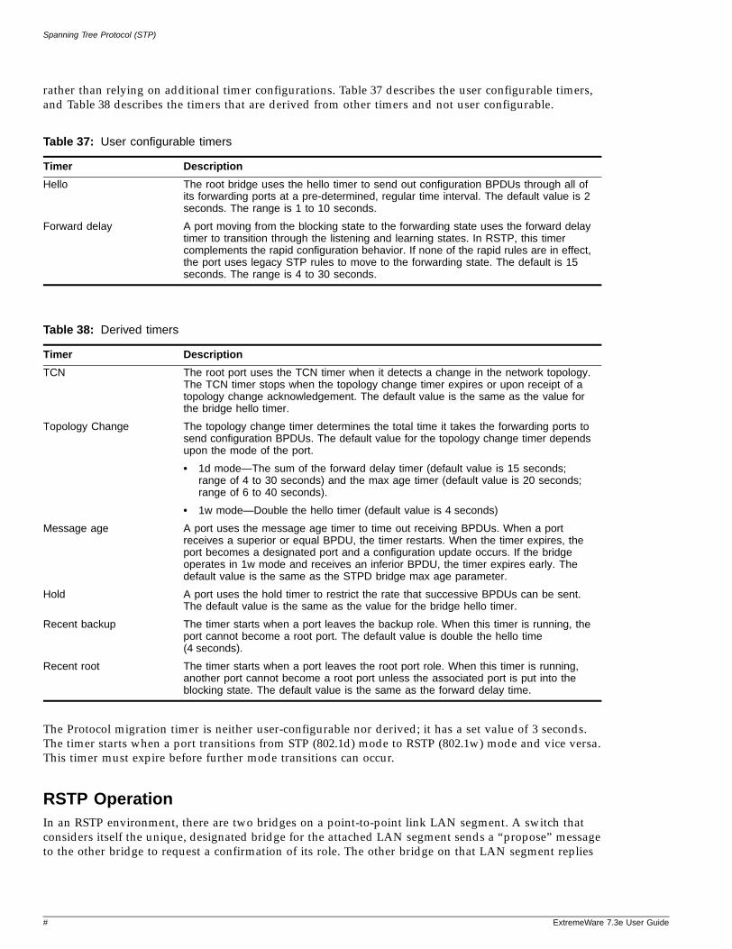
Spanning Tree Protocol (STP)
rather than relying on additional timer configurations. Table 37 describes the user configurable timers, and Table 38 describes the timers that are derived from other timers and not user configurable.
The Protocol migration timer is neither user-configurable nor derived; it has a set value of 3 seconds. The timer starts when a port transitions from STP (802.1d) mode to RSTP (802.1w) mode and vice versa. This timer must expire before further mode transitions can occur.
RSTP OperationIn an RSTP environment, there are two bridges on a point-to-point link LAN segment. A switch that considers itself the unique, designated bridge for the attached LAN segment sends a “propose” message to the other bridge to request a confirmation of its role. The other bridge on that LAN segment replies
Table 37: User configurable timers
Timer Description
Hello The root bridge uses the hello timer to send out configuration BPDUs through all of its forwarding ports at a pre-determined, regular time interval. The default value is 2 seconds. The range is 1 to 10 seconds.
Forward delay A port moving from the blocking state to the forwarding state uses the forward delay timer to transition through the listening and learning states. In RSTP, this timer complements the rapid configuration behavior. If none of the rapid rules are in effect, the port uses legacy STP rules to move to the forwarding state. The default is 15 seconds. The range is 4 to 30 seconds.
Table 38: Derived timers
Timer Description
TCN The root port uses the TCN timer when it detects a change in the network topology. The TCN timer stops when the topology change timer expires or upon receipt of a topology change acknowledgement. The default value is the same as the value for the bridge hello timer.
Topology Change The topology change timer determines the total time it takes the forwarding ports to send configuration BPDUs. The default value for the topology change timer depends upon the mode of the port.
• 1d mode—The sum of the forward delay timer (default value is 15 seconds; range of 4 to 30 seconds) and the max age timer (default value is 20 seconds; range of 6 to 40 seconds).
• 1w mode—Double the hello timer (default value is 4 seconds)
Message age A port uses the message age timer to time out receiving BPDUs. When a port receives a superior or equal BPDU, the timer restarts. When the timer expires, the port becomes a designated port and a configuration update occurs. If the bridge operates in 1w mode and receives an inferior BPDU, the timer expires early. The default value is the same as the STPD bridge max age parameter.
Hold A port uses the hold timer to restrict the rate that successive BPDUs can be sent. The default value is the same as the value for the bridge hello timer.
Recent backup The timer starts when a port leaves the backup role. When this timer is running, the port cannot become a root port. The default value is double the hello time (4 seconds).
Recent root The timer starts when a port leaves the root port role. When this timer is running, another port cannot become a root port unless the associated port is put into the blocking state. The default value is the same as the forward delay time.
# ExtremeWare 7.3e User Guide
Running H/F 1
ExtremeWare 7
with an “agree” message if they agree with the proposal. The receiving bridge immediately moves its designated port into the forwarding state.
Before a bridge replies with an “agree” message, it reverts all of its designated ports into the blocking state. This introduces a temporary partition into the network. The bridge then sends another “propose” message on all of its designated ports for further confirmation. Since all of the connections are blocked, the bridge immediately sends an “agree” message to unblock the proposing port without having to wait for further confirmations to come back or without the worry of temporary loops.
Beginning with the root bridge, each bridge in the network engages in the exchange of “propose” and “agree” messages until they reach the edge ports. Edge ports connect to non-STP devices and do not participate in RSTP. Their role does not need to be confirmed. If an edge port receives a BPDU, it enters an inconsistency state. An inconsistency state puts the edge port into the blocking state and starts the message age timer. Every time the edge port receives a BPDU, the message age timer restarts. The edge port remains in the blocking state until no further BPDUs are received and the message age timer expires.
RSTP attempts to transition root ports and designated ports to the forwarding state and alternate ports and backup ports to the blocking state as rapidly as possible.
A port transitions to the forwarding state if any of the following is true. The port:
• Has been in either a root or designated port role long enough that the spanning tree information supporting this role assignment has reached all of the bridges in the network.
NOTE
RSTP is backward compatible with STP, so if a port does not move to the forwarding state with any of the RSTP rapid transition rules, a forward delay timer starts and STP behavior takes over.
• Is now a root port and no other ports have a recent role assignment that contradicts with its root port role.
• Is a designated port and attaches to another bridge by a point-to-point link and receives an “agree” message from the other bridge port.
• Is an edge port.
An edge port is a port connected to a non-STP device and is in the forwarding state.
The preceding sections provide more information about RSTP behavior.
Root Port Rapid Behavior
In Figure 31, the diagram on the left displays the initial network topology with a single bridge having the following:
• Two ports connected to a shared LAN segment
• One port is the designated port
• One port is the backup port
The diagram on the right displays a new bridge that:
• Is connected to the LAN segment
• Has a superior STP bridge priority
.3e User Guide #
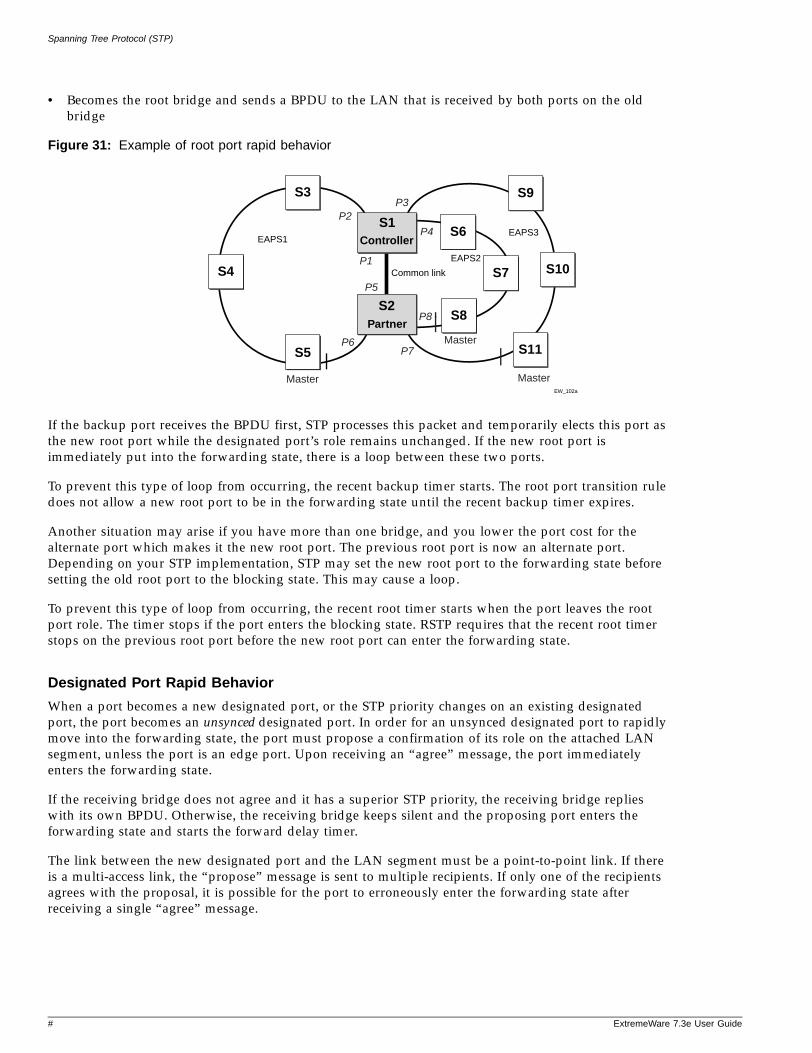
Spanning Tree Protocol (STP)
• Becomes the root bridge and sends a BPDU to the LAN that is received by both ports on the old bridge
Figure 31: Example of root port rapid behavior
If the backup port receives the BPDU first, STP processes this packet and temporarily elects this port as the new root port while the designated port’s role remains unchanged. If the new root port is immediately put into the forwarding state, there is a loop between these two ports.
To prevent this type of loop from occurring, the recent backup timer starts. The root port transition rule does not allow a new root port to be in the forwarding state until the recent backup timer expires.
Another situation may arise if you have more than one bridge, and you lower the port cost for the alternate port which makes it the new root port. The previous root port is now an alternate port. Depending on your STP implementation, STP may set the new root port to the forwarding state before setting the old root port to the blocking state. This may cause a loop.
To prevent this type of loop from occurring, the recent root timer starts when the port leaves the root port role. The timer stops if the port enters the blocking state. RSTP requires that the recent root timer stops on the previous root port before the new root port can enter the forwarding state.
Designated Port Rapid Behavior
When a port becomes a new designated port, or the STP priority changes on an existing designated port, the port becomes an unsynced designated port. In order for an unsynced designated port to rapidly move into the forwarding state, the port must propose a confirmation of its role on the attached LAN segment, unless the port is an edge port. Upon receiving an “agree” message, the port immediately enters the forwarding state.
If the receiving bridge does not agree and it has a superior STP priority, the receiving bridge replies with its own BPDU. Otherwise, the receiving bridge keeps silent and the proposing port enters the forwarding state and starts the forward delay timer.
The link between the new designated port and the LAN segment must be a point-to-point link. If there is a multi-access link, the “propose” message is sent to multiple recipients. If only one of the recipients agrees with the proposal, it is possible for the port to erroneously enter the forwarding state after receiving a single “agree” message.
EW_102a
S4
S5
S3
EAPS1
Partner
S9
S11
S10
S1
S2
EAPS2
EAPS3Controller
S6
S8
S7
Master
Master
Master
P1
P2P3
P4
P5
P6P7
P8
Common link
# ExtremeWare 7.3e User Guide
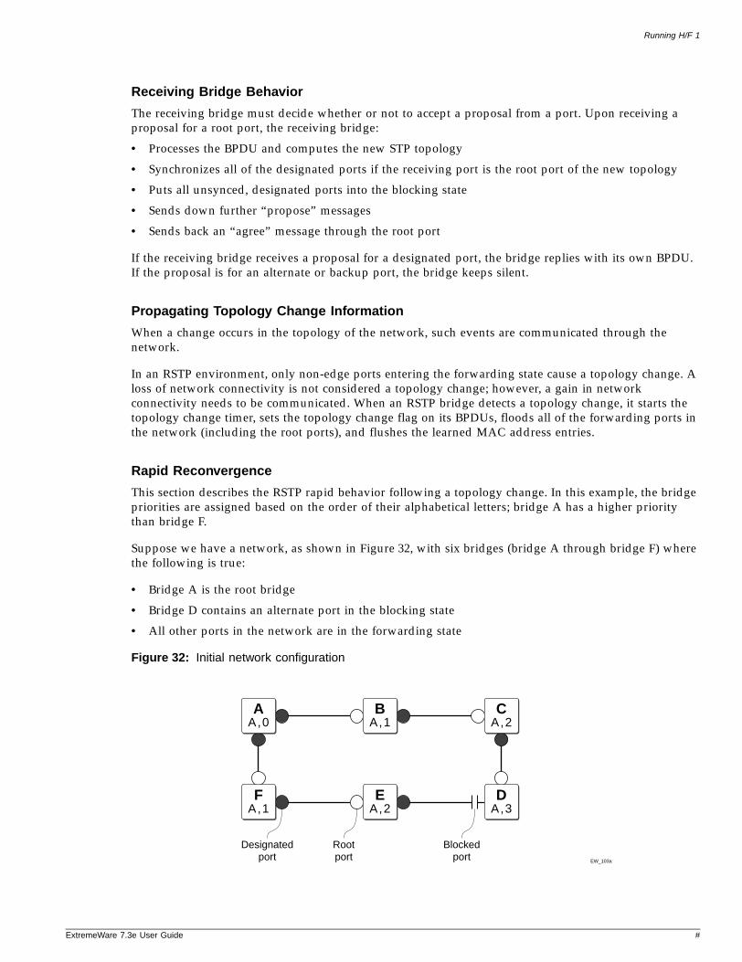
Running H/F 1
ExtremeWare 7
Receiving Bridge Behavior
The receiving bridge must decide whether or not to accept a proposal from a port. Upon receiving a proposal for a root port, the receiving bridge:
• Processes the BPDU and computes the new STP topology
• Synchronizes all of the designated ports if the receiving port is the root port of the new topology
• Puts all unsynced, designated ports into the blocking state
• Sends down further “propose” messages
• Sends back an “agree” message through the root port
If the receiving bridge receives a proposal for a designated port, the bridge replies with its own BPDU. If the proposal is for an alternate or backup port, the bridge keeps silent.
Propagating Topology Change Information
When a change occurs in the topology of the network, such events are communicated through the network.
In an RSTP environment, only non-edge ports entering the forwarding state cause a topology change. A loss of network connectivity is not considered a topology change; however, a gain in network connectivity needs to be communicated. When an RSTP bridge detects a topology change, it starts the topology change timer, sets the topology change flag on its BPDUs, floods all of the forwarding ports in the network (including the root ports), and flushes the learned MAC address entries.
Rapid Reconvergence
This section describes the RSTP rapid behavior following a topology change. In this example, the bridge priorities are assigned based on the order of their alphabetical letters; bridge A has a higher priority than bridge F.
Suppose we have a network, as shown in Figure 32, with six bridges (bridge A through bridge F) where the following is true:
• Bridge A is the root bridge
• Bridge D contains an alternate port in the blocking state
• All other ports in the network are in the forwarding state
Figure 32: Initial network configuration
Designatedport
Rootport EW_103a
AA , 0
BA , 1
CA , 2
FA , 1
EA , 2
DA , 3
Blockedport
.3e User Guide #
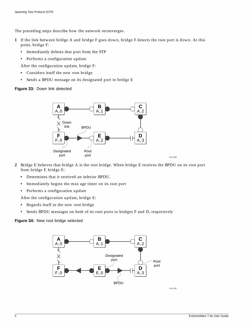
Spanning Tree Protocol (STP)
The preceding steps describe how the network reconverges.
1 If the link between bridge A and bridge F goes down, bridge F detects the root port is down. At this point, bridge F:
• Immediately deletes that port from the STP
• Performs a configuration update
After the configuration update, bridge F:
• Considers itself the new root bridge
• Sends a BPDU message on its designated port to bridge E
Figure 33: Down link detected
2 Bridge E believes that bridge A is the root bridge. When bridge E receives the BPDU on its root port from bridge F, bridge E:
• Determines that it received an inferior BPDU.
• Immediately begins the max age timer on its root port
• Performs a configuration update
After the configuration update, bridge E:
• Regards itself as the new root bridge
• Sends BPDU messages on both of its root ports to bridges F and D, respectively
Figure 34: New root bridge selected
EW_103b
BA , 1
CA , 2
EA , 2
DA , 3
BPDUDownlink
AA , 0
FF , 0
Designatedport
Rootport
EW_103c
BA , 1
CA , 2
EE , 0
DA , 3
BPDU
AA , 0
FF , 0
Designatedport Root
port
# ExtremeWare 7.3e User Guide
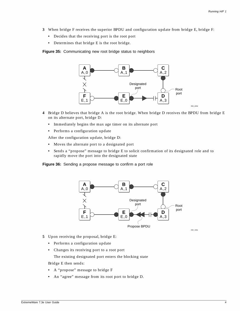
Running H/F 1
ExtremeWare 7
3 When bridge F receives the superior BPDU and configuration update from bridge E, bridge F:
• Decides that the receiving port is the root port
• Determines that bridge E is the root bridge.
Figure 35: Communicating new root bridge status to neighbors
4 Bridge D believes that bridge A is the root bridge. When bridge D receives the BPDU from bridge E on its alternate port, bridge D:
• Immediately begins the max age timer on its alternate port
• Performs a configuration update
After the configuration update, bridge D:
• Moves the alternate port to a designated port
• Sends a “propose” message to bridge E to solicit confirmation of its designated role and to rapidly move the port into the designated state
Figure 36: Sending a propose message to confirm a port role
5 Upon receiving the proposal, bridge E:
• Performs a configuration update
• Changes its receiving port to a root port
The existing designated port enters the blocking state
Bridge E then sends:
• A “propose” message to bridge F
• An “agree” message from its root port to bridge D.
EW_103d
BA , 1
CA , 2
EE , 0
DA , 3
AA , 0
FE , 1
Designatedport Root
port
EW_103e
BA , 1
CA , 2
EE , 0
Propose BPDU
AA , 0
FE , 1
DA , 3
Designatedport Root
port
.3e User Guide #
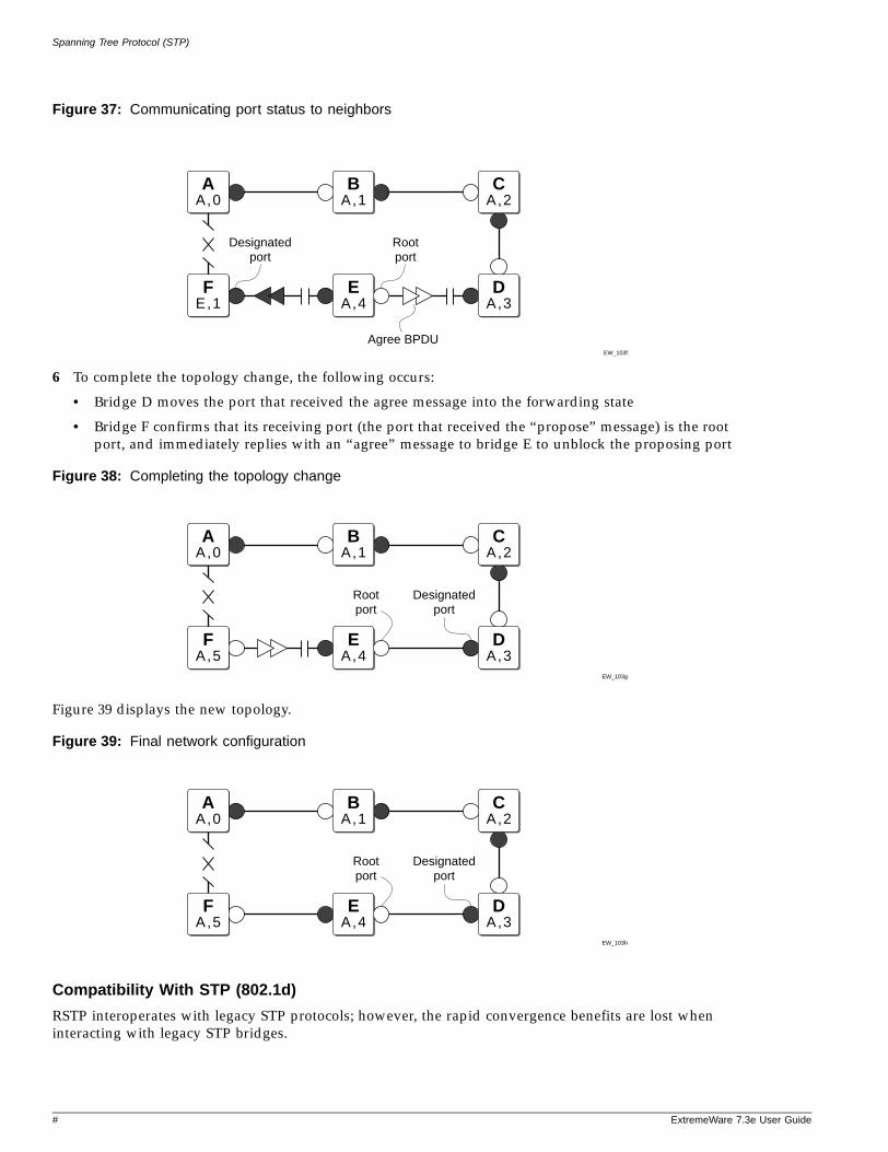
Spanning Tree Protocol (STP)
Figure 37: Communicating port status to neighbors
6 To complete the topology change, the following occurs:
• Bridge D moves the port that received the agree message into the forwarding state
• Bridge F confirms that its receiving port (the port that received the “propose” message) is the root port, and immediately replies with an “agree” message to bridge E to unblock the proposing port
Figure 38: Completing the topology change
Figure 39 displays the new topology.
Figure 39: Final network configuration
Compatibility With STP (802.1d)
RSTP interoperates with legacy STP protocols; however, the rapid convergence benefits are lost when interacting with legacy STP bridges.
EW_103f
BA , 1
CA , 2
EA , 4
Agree BPDU
AA , 0
FE , 1
DA , 3
Designatedport
Rootport
EW_103g
BA , 1
CA , 2
EA , 4
DA , 3
AA , 0
FA , 5
Designatedport
Rootport
EW_103h
BA , 1
CA , 2
EA , 4
DA , 3
AA , 0
FA , 5
Designatedport
Rootport
# ExtremeWare 7.3e User Guide
Running H/F 1
ExtremeWare 7
Each RSTP bridge contains a port protocol migration state machine to ensure that the ports in the STPD operate in the correct, configured mode. The state machine is a protocol entity within each bridge configured to run in 802.1w mode. For example, a compatibility issue occurs if you configure 802.1w mode and the bridge receives an 802.1d BPDU on a port. The receiving port starts the protocol migration timer and remains in 802.1d mode until the bridge stops receiving 802.1d BPDUs. Each time the bridge receives an 802.1d BPDU, the timer restarts. When the port migration timer expires, no more 802.1d BPDUs have been received and the bridge returns to its configured setting, 802.1w mode.
STP Rules and Restrictions
This section summarizes the rules and restrictions for configuring STP.
• EMISTP and PVST+ only operates in compatibility mode on the series “e” switches. As stated before, a VLAN can span multiple STPDs. However, on the switch, there is a hardware limitation that restricts each physical port to a single STPD. If the port is already a member of an STPD, then that port cannot be in another VLAN that is in a different STPD, or not in a STPD at all.
• The StpdID must be the VLANid of one of its member VLANs, and that VLAN can not be partitioned.
• A default VLAN can not be partitioned. If a VLAN traverses multiple STP domains, the VLAN must be tagged.
• If a port supports 802.1w-STPD, then the port must be configured with a default VLAN. If not, the BPDUs for that STPD are not flooded when the STPD is disabled.
Configuring STP on the Switch
To configure basic STP, follow these steps:
1 Create one or more STP domains using the following command:
create stpd <name>
NOTE
STPD, VLAN, and QoS profile names must all be unique. For example, a name used to identify a VLAN cannot be used when you create an STPD or a QoS profile.
2 Add one or more VLANs to the STPD using the following command:
configure stpd <spanning tree name> add vlan <vlan name> {ports <portlist> [dot1d | emistp |pvst-plus]}
3 Enable STP for one or more STP domains using the following command:
enable stpd {<spanning tree name>}
After you have created the STPD, you can optionally configure STP parameters for the STPD.
NOTE
You should not configure any STP parameters unless you have considerable knowledge and experience with STP. The default STP parameters are adequate for most networks.
.3e User Guide #
Spanning Tree Protocol (STP)
The following parameters can be configured on each STPD:
• Hello time
• Forward delay
• Max age
• Bridge priority
• StpdID
The following parameters can be configured on each port:
• Path cost
• Port priority
• Port mode
NOTE
The device supports the RFC 1493 Bridge MIB. Parameters of only the s0 default STPD are accessible through this MIB.
NOTE
If an STPD contains at least one port not in dot1D mode, the STPD must be configured with an StpdID.
STP Configuration ExamplesThis section provides three configuration examples:
• Basic 802.1d STP
• RSTP 802.1w
Basic 802.1d Configuration Example
The following example creates and enables an STPD named Backbone_st. It assigns the Manufacturing VLAN to the STPD. It disables STP on ports 1 through 7, and port 12.
create stpd backbone_stconfigure stpd backbone_st add vlan manufacturingenable stpd backbone_stdisable stpd backbone_st port 1-7,12
RSTP 802.1w Configuration Example
Figure 40 is an example of a network with multiple STPDs that can benefit from RSTP. For RSTP to work, you need to do the following:
• Create an STPD
• Configure the mode of operation for the STPD
• Create the VLANs and assign the ports
• Add the VLANs to the STPD
• Configure the port link types
# ExtremeWare 7.3e User Guide
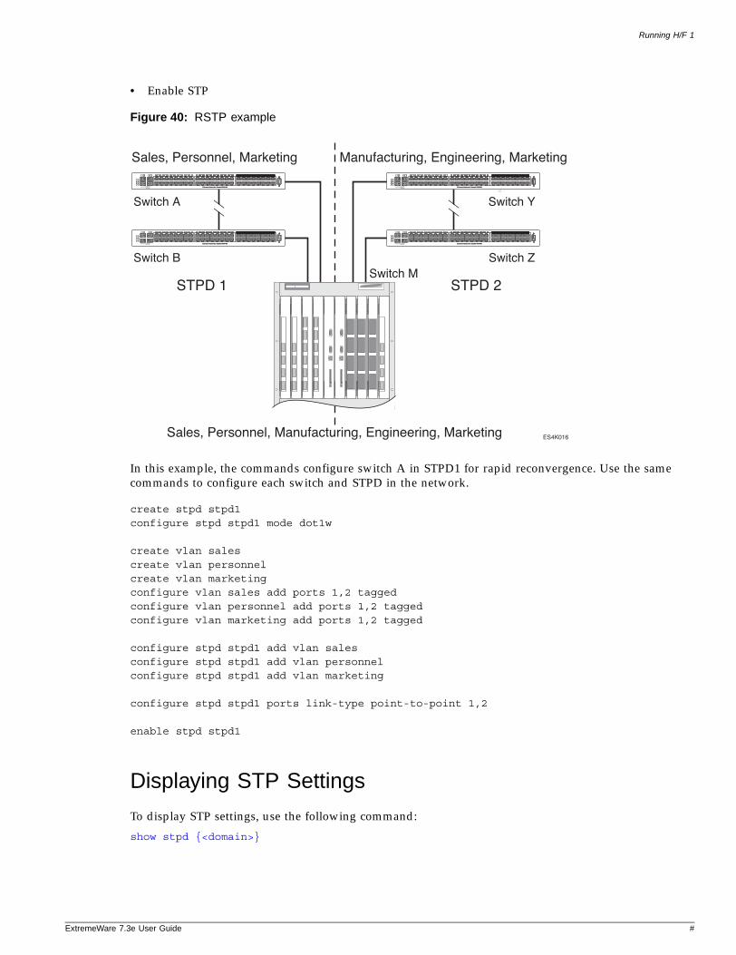
Running H/F 1
ExtremeWare 7
• Enable STP
Figure 40: RSTP example
In this example, the commands configure switch A in STPD1 for rapid reconvergence. Use the same commands to configure each switch and STPD in the network.
create stpd stpd1configure stpd stpd1 mode dot1w
create vlan salescreate vlan personnelcreate vlan marketingconfigure vlan sales add ports 1,2 taggedconfigure vlan personnel add ports 1,2 taggedconfigure vlan marketing add ports 1,2 tagged
configure stpd stpd1 add vlan salesconfigure stpd stpd1 add vlan personnelconfigure stpd stpd1 add vlan marketing
configure stpd stpd1 ports link-type point-to-point 1,2
enable stpd stpd1
Displaying STP Settings
To display STP settings, use the following command:
show stpd {<domain>}
ES4K016
Sales, Personnel, Marketing
STPD 1 STPD 2
Manufacturing, Engineering, Marketing
Sales, Personnel, Manufacturing, Engineering, Marketing
Switch A Switch Y
Switch ZSwitch M
Switch B
.3e User Guide #
Spanning Tree Protocol (STP)
This command displays the following information:
• STPD name
• STPD state
• STPD mode of operation
• Rapid Root Failover
• Tag
• Ports
• Active VLANs
• Bridge Priority
• Bridge ID
• Designated root
• STPD configuration information
To display the STP state of a port, use the following command:
show stpd <spanning tree name> ports <portlist| {vlan} <vlan name>>
This command displays the following information:
• STPD port configuration
• STPD port mode of operation
• STPD path cost
• STPD priority
• STPD state (root bridge, and so on)
• Port role (root bridge, edge port, etc.)
• STPD port state (forwarding, blocking, and so on)
• Configured port link type
• Operational port link type
If you have a VLAN that spans multiple STPDs, use the show vlan <vlan name> stpd command to display the STP configuration of the ports assigned to that specific VLAN.
The command displays the following:
• STPD port configuration
• STPD port mode of operation
• STPD path cost
• STPD priority
• STPD state (root bridge, and so on)
• Port role (root bridge, edge port, etc.)
• STPD port state (forwarding, blocking, and so on)
• Configured port link type
• Operational port link type
# ExtremeWare 7.3e User Guide
15 Extreme Standby Router Protocol
ExtremeWare 7
This chapter covers the following topics:
• Overview of ESRP on page 285
• ESRP Concepts on page 287
• Determining the ESRP Master on page 288
• Advanced ESRP Features on page 291
• Displaying ESRP Information on page 300
• ESRP Examples on page 304
• ESRP Cautions on page 307
Overview of ESRP
ESRP is a feature of ExtremeWare that allows multiple switches to provide redundant routing services to users. From the workstation’s perspective, there is only one default router (that has one IP address and one MAC address), so ARP cache entries in client workstations do not need to be refreshed or aged-out.
In addition to providing layer 3 routing redundancy for IP and IPX, ESRP also provides for layer 2 redundancy. These “layered” redundancy features can be used in combination or independently. You do not have to configure the switch for routing to make valuable use of ESRP. The layer 2 redundancy features of ESRP offer fast failure recovery and provide for dual-homed system design. In some instances, depending on network system design, ESRP can provide better resiliency than using Spanning Tree Protocol (STP) or Virtual Router Redundancy Protocol (VRRP).
We recommended that all switches participating in ESRP run the same version of ExtremeWare. Not all ESRP features are available in all ExtremeWare software releases.
Reasons to Use ESRP
You can use ESRP when working with edge-level or aggregation-level redundancy. Deploying ESRP in this area of the network allows you to simplify your network design which is important in designing a stable network. ESRP also works well in meshed networks where layer 2 loop protection and layer 3 redundancy are simultaneously required.
.3e User Guide 285
Extreme Standby Router Protocol
ESRP TermsTable 39 describes terms associated with ESRP.
Table 39: ESRP Terms
Term Description
ESRP-aware An Extreme switch that is capable of listening to EDP which is the protocol that ESRP uses to transmit information. For more information see “ESRP Concepts” on page 287.
ESRP-enabled An Extreme switch with the ESRP feature enabled. ESRP-enabled switches include the ESRP master and slave switches.
EDP Extreme Discovery Protocol. A protocol used by ESRP to communicate information about neighbor Extreme switches. The master and the slave utilize EDP to send hello packets that contain timers, port count, and other state information pertinent to ESRP.
master switch The master switch is the device with the highest priority based on the election algorithm. The master is responsible for responding to clients for layer 3 routing and layer 2 switching for the VLAN. For more information about the master switch, see “Determining the ESRP Master” on page 288.
pre-master state An ESRP switch that is ready to be master but is going through possible loop detection prior to transitioning to master. For more information about the behavior of the pre-master switch, see “Pre-Master Switch Behavior” on page 289.
slave switch A switch participating in ESRP that is not elected or configured the master. The slave switch does not respond to ARP requests, but it does exchange EDP packets with other switches on the same VLAN. The slave switch is available to assume the responsibilities of the master switch if the master becomes unavailable or criteria for ESRP changes. For more information about the behavior of the slave switch, see “Slave Switch Behavior” on page 289.
election algorithm A user-defined criteria to determine how the master and the slave interact with each other. The election algorithm also determines which device becomes the master or the slave and how ESRP makes those decisions. For more information about the election algorithms, see “ESRP Election Algorithms” on page 290.
priority A user-defined field to set the priority values for ESRP. The range of the priority value is 0 to 255; a higher number has higher priority. The default priority setting is 0. A priority setting of 255 loses the election and the switch remains in slave mode. To learn more about configuring priority values for ESRP, see “Electing the Master Switch” on page 289.
tracking ESRP uses tracking mechanisms to determine a master. Should the ESRP master lose the ability to track a selected mechanism, the ESRP slave assumes master. For more information about the tracking methods used by ESRP, see “ESRP Tracking” on page 291.
domains Domains are a method of increasing scalability for ESRP by creating a domain master VLAN that controls ESRP election and failover criteria for member-VLANs.
domain master-VLAN The VLAN that ESRP is enabled on and controls the member-VLANs.
domain member-VLAN The VLAN that is controlled by the ESRP domain master-VLAN. ESRP cannot be enabled on this VLAN.
ESRP VLAN A VLAN that has ESRP enabled.
ESRP instance You enable ESRP on a per-VLAN basis. Each time you enable ESRP on a VLAN is an ESRP instance.
286 ExtremeWare 7.3e User Guide
ESRP Concepts
ExtremeWare 7
ESRP Concepts
ESRP is configured on a per-VLAN basis on each switch. A maximum of four switches can participate in providing redundant layer 3 or layer 2 services to a single VLAN. The switches exchange keep-alive packets for each VLAN independently. Only one switch (the master) can actively provide layer 3 routing and/or layer 2 switching for each VLAN. This switch handles the forwarding, ARP requests, and routing for this particular VLAN. Other participating switches for the VLAN are in slave mode waiting for an ESRP state change.
For a VLAN with ESRP enabled, each participating switch uses the same MAC address and must be configured with the same IP address or IPX NetID. It is possible for one switch to be master for one or more VLANs while being in slave for others, thus allowing the load to be split across participating switches.
NOTE
If you configure OSPF and ESRP, you must manually configure an OSPF router identifier (ID). Be sure that you configure a unique OSPF router ID on each switch running ESRP. For more information on configuring OSPF, see Chapter 18.
To have two or more switches participate in ESRP, the following must be true:
• For each VLAN to be made redundant, the switches must have the ability to exchange packets on the same layer 2 broadcast domain for that VLAN. Multiple paths of exchange can be used, and typically exist in most network system designs that take advantage of ESRP.
• For a VLAN to be recognized as participating in ESRP, the assigned IP address or the IPX NETid for the separate switches must be identical. Other aspects of the VLAN, including its name, are ignored.
• ESRP must be enabled on the desired VLANs for each switch.
NOTE
ESRP cannot be enabled on the VLAN default.
• Extreme Discovery Protocol (EDP) must be enabled on the ports that are members of the ESRP VLANs (The default setting is enabled.).
NOTE
If you configure a domain master-VLAN for ESRP, the domain master-VLAN must contain all ports belonging to the domain member-VLANs in order to operate properly as an ESRP VLAN.
ESRP-Aware SwitchesExtreme switches that are not running ESRP, but are connected on a network that has other Extreme switches running ESRP are ESRP-aware. When ESRP-aware switches are attached to ESRP-enabled switches, the ESRP-aware switches reliably perform fail-over and fail-back scenarios in the prescribed recovery times. No configuration of this feature is necessary.
NOTE
If you disable EDP on the switch, the switch is no longer ESRP-aware.
.3e User Guide 287
Extreme Standby Router Protocol
If Extreme switches running ESRP are connected to layer 2 switches that are not manufactured by Extreme Networks, the fail-over times seen for traffic local to the segment may appear longer, depending on the application involved and the FDB timer used by the other vendor’s layer 2 switch. As such, ESRP can be used with layer 2 switches from other vendors, but the recovery times vary.
The VLANs associated with the ports connecting an ESRP-aware switch to an ESRP-enabled switch must be configured using an 802.1Q tag on the connecting port, or, if only a single VLAN is involved, as untagged using the protocol filter any. ESRP will not function correctly if the ESRP-aware switch interconnection port is configured for a protocol-sensitive VLAN using untagged traffic. You can also use port restart in this scenario. For more information about port restart, see “ESRP Port Restart” on page 295.
To display ESRP-aware information, use the following command:
show esrp-aware vlan <vlan name>
The display includes the group number, MAC address for the master of the group, and age of the information.
Linking ESRP SwitchesWhen considering system design using ESRP, Extreme Networks recommends using a direct link. Direct links between ESRP switches are useful under the following conditions:
• A direct link can provide a more direct routed path, if the ESRP switches are routing and supporting multiple VLANs where the master/slave configuration is split such that one switch is master for some VLANs and a second switch is master for other VLANs. The direct link can contain a unique router-to-router VLAN/subnet, so that the most direct routed path between two VLANs with different master switches uses a direct link, instead of forwarding through another set of connected routers.
• A direct link can be used as a highly reliable method to exchange ESRP hellos, so that the possibility of having multiple masters for the same VLAN is lessened, should all downstream layer 2 switches fail.
• A direct link is necessary for the ESRP HA option. The direct link is used to provide layer 2 forwarding services through an ESRP slave switch.
Direct links may contain a router-to-router VLAN, along with VLANs running ESRP. If multiple VLANs are used on the direct links, use 802.1Q tagging. The direct links may be aggregated into a load-shared group, if desired. If multiple ESRP VLANs share a host port, each VLAN must be in a different ESRP group.
Determining the ESRP Master
The ESRP master switch (providing layer 3 routing and/or layer 2 switching services for a VLAN) is determined by the following default factors:
• Active ports—The switch that has the greatest number of active ports takes highest precedence.
• Tracking information—Various types of tracking are used to determine if the switch performing the master ESRP function has connectivity to the outside world. ExtremeWare supports the following types of tracking:
— VLAN—Tracks any active port connectivity to one or more designated VLANs
288 ExtremeWare 7.3e User Guide
Determining the ESRP Master
ExtremeWare 7
— IP route table entry—Tracks specific learned routes from the IP route table
— Ping—Tracks ICMP ping connectivity to specified devices
— Diagnostics—Tracks the diagnostics of the switch
— Environment (health checks)—Tracks the environment of the switch
If any of the configured tracking mechanisms fail, the master ESRP switch relinquishes status as master, and remains in slave mode for as long as the tracking mechanism continues to fail.
• ESRP priority—This is a user-defined field. The range of the priority value is 0 to 255; a higher number has higher priority. The default priority setting is 0. A priority setting of 255 makes an ESRP switch remain in slave mode and is the recommended setting for system maintenance. A switch with a priority setting of 255 will never become the master.
• System MAC address—The switch with the higher MAC address has higher priority.
Master Switch BehaviorIf a switch is master, it actively provides layer 3 routing services to other VLANs, and layer 2 switching between all the ports of that VLAN. Additionally, the switch exchanges EDP packets with other switches that are in slave mode.
Pre-Master Switch BehaviorA pre-master switch is ready to transition to master, but is going through possible loop detection prior to changing to the master state. This temporary state avoids the possibility of having simultaneous masters.
Slave Switch BehaviorIf a switch is in slave mode, it exchanges EDP packets with other switches on that same VLAN. When a switch is in slave mode, it does not perform layer 3 routing or layer 2 switching services for the VLAN. From a layer 3 routing protocol perspective (for example, RIP or OSPF), when in slave mode for the VLAN, the switch marks the router interface associated with the VLAN as down. From a layer 2 switching perspective, no forwarding occurs between the member ports of the VLAN; this prevents loops and maintains redundancy.
If you configure the switch to use the optional ESRP Host Attach configuration, the switch continues layer 2 forwarding to the master. For more information, see “ESRP Host Attach” on page 296.
Electing the Master SwitchA new master can be elected in one of the following ways:
• A communicated parameter change
• Loss of communication between master and slave(s)
If a parameter that determines the master changes (for example, link loss or priority change), the election of the new master typically occurs within one timer cycle (2 seconds by default). If a switch in slave mode loses its connection with the master, a new election (using the same precedence order indicated previously) occurs. The new election typically takes place in three times the defined timer cycle (6 seconds by default).
.3e User Guide 289
Extreme Standby Router Protocol
Before the switch transitions to the master state, the switch enters a temporary pre-master state. While in the pre-master state the VLAN does not send ESRP PDUs until the pre-master state timeout expires. When the timeout expires, the slave VLAN operates normally. Traffic is unaffected by the pre-master state because the master continues to operate normally. The pre-master state avoids the possibility of having simultaneous masters.
You can configure the pre-master state timeout using the following command:
configure vlan <vlan name> esrp esrp-premaster-timeout <premaster-timer (0-512, 0 restores dflt)>
CAUTION
Configure the pre-master state timeout only with guidance from Extreme Networks personnel. Misconfiguration can severely degrade the performance of ESRP and your switch.
Failover TimeFailover time is largely determined by the following factors:
• The ESRP timer setting.
• The routing protocol being used for inter-router connectivity if layer 3 redundancy is used. OSPF failover time is faster than RIP failover time.
The failover time associated with the ESRP protocol is dependent on the timer setting and the nature of the failure. The default timer setting is 2 seconds; the range is 1 to 255 seconds. In most cases, a non-hardware failover is 2 seconds and a hardware failover is 6 seconds.
If routing is configured, the failover of the particular routing protocol (such as RIP V1, RIP V2, or OSPF) is added to the failover time associated with ESRP.
If you use OSPF, make your OSPF configuration passive. A passive configuration acts as a stub area and helps increase the time it takes for recalculating the network. A passive configuration also maintains a stable OSPF core.
ESRP Election Algorithms
You configure the switch to use one of seven different election algorithms to select the ESRP master. Each algorithm considers the election factors in a different order of precedence, as follows:
• ports-track-priority-mac—Active ports, tracking information, ESRP priority, MAC address (Default)
• ports-track-priority—Active ports, tracking information, ESRP priority
• track-ports-priority-mac—Tracking information, active ports, ESRP priority, MAC address
• track-ports-priority—Tracking information, active ports, ESRP priority
• priority-ports-track-mac—ESRP priority, active ports, tracking information, MAC address
• priority-track-ports-mac—ESRP priority, tracking information, active ports, MAC address
• priority-mac-only—ESRP priority, MAC address
290 ExtremeWare 7.3e User Guide

Advanced ESRP Features
ExtremeWare 7
CAUTION
All switches in the ESRP network must use the same election algorithm, otherwise loss of connectivity, broadcast storms, or other unpredictable behavior may occur.
Advanced ESRP Features
This section describes the following advanced ESRP features:
• ESRP Tracking on page 291
• ESRP Port Restart on page 295
• ESRP and VLAN Aggregation on page 295
• ESRP Host Attach on page 296
• ESRP Don’t Count on page 297
• ESRP Domains on page 297
• ESRP Groups on page 298
• Selective Forwarding on page 299
ESRP TrackingTracking information is used to track various forms of connectivity from the ESRP switch to the outside world. This section describes the following ESRP tracking options:
• ESRP Environment and Diagnostic Tracking on page 291
• ESRP VLAN Tracking on page 292
• ESRP Route Table Tracking on page 292
• ESRP Ping Tracking on page 292
• OSPF Tracking on page 293
• RIP Tracking on page 293
ESRP Environment and Diagnostic Tracking
You can configure ESRP to track hardware status. If a power supply or fan fails, if the chassis is overheating, if a non-fully loaded power supply is detected, or if the diagnostics fail, the priority for the ESRP VLAN will change to the failover settings. You can track the environment, diagnostics, or both at the same time.
To configure the failover priority for ESRP VLAN, follow these steps:
1 Assign a priority to each ESRP VLAN, using the following command:
configure vlan <vlan name> esrp priority <value>
The range of the priority value is 0 to 254; a higher number has a higher priority. The default priority setting is 0.
.3e User Guide 291
Extreme Standby Router Protocol
NOTE
If you set the priority to 255, the ESRP VLAN will remain in slave mode even if the master ESRP VLAN fails.
You will typically configure both ESRP VLANs with the same priority.
2 Assign the priority flag precedence over the active ports count, using the following command:
configure vlan <vlan name> esrp esrp-election [ports-track-priority | ports-track-priority-mac | track-ports-priority | track-ports-priority-mac | priority-ports-track-mac | priority-track-ports-mac | priority-mac-only]
Because the priority of both ESRP VLANs are set to the same value, ESRP will use the active ports count to determine the master ESRP VLAN.
3 Set the failover priority, using the following command:
configure vlan <vlan name> add track-diagnostic failover <priority>
The range of the priority value is 0 to 254; a higher number has a higher priority. The default priority setting is 0.
Typically you will set the failover priority lower than the configured priority. Then, if one of the ESRP VLANs experiences a hardware or diagnostics failure, it will become the standby VLAN.
ESRP VLAN Tracking
You can configure ESRP to track port connectivity to one or more specified VLANs as criteria for failover. The number of VLAN active ports are tracked. If the switch is no longer connected to the specified VLANs, the switch automatically relinquishes master status and remains in slave mode. You can track a maximum of four routes per VLAN.
To add or delete a tracked VLAN, use one of the following commands:
configure vlan <vlan name> add track-vlan <vlan_tracked>>configure vlan <vlan name> delete track-vlan <vlan_tracked>
ESRP Route Table Tracking
You can configure ESRP to track specified routes in the route table as criteria for failover. If all of the configured routes are not available within the route table, the switch automatically relinquishes master status and remains in slave mode. You can track a maximum of four routes per route table.
To participate in ESRP route table tracking, all ESRP switches must run either ExtremeWare for “e” series switches (any version or release) or ExtremeWare for “i” chipsets (version 6.0 or above).
To add or delete a tracked route, use one of the following commands:
configure vlan <vlan name> add track-iproute <ip address>/<masklength> configure vlan <vlan name> delete track-iproute <ipaddress>/<masklength>
ESRP Ping Tracking
You can configure ESRP to track connectivity using a simple ping to any device. This may represent the default route of the switch, or any device meaningful to network connectivity of the master ESRP switch. The switch automatically relinquishes master status and remains in slave mode if a ping keepalive fails. You can configure a maximum of four ping tracks.
292 ExtremeWare 7.3e User Guide
Advanced ESRP Features
ExtremeWare 7
NOTE
The ESRP ping tracking option cannot be configured to ping an IP address within an ESRP VLAN subnet. It should be configured on some other normal VLAN across the router boundary.
To participate in ESRP ping tracking, all ESRP switches must run either ExtremeWare for “e” series switches (any version or release) or ExtremeWare for “i” chipsets (version 6.0 or above).
To view the status of tracked devices, use the following command:
show esrp {detail}
To configure ping tracking, use the following command:
configure vlan <vlan name> add track-ping <ip address> frequency <seconds> miss <number>
OSPF Tracking
You can configure ESRP to track any available OSPF routes as a criteria for failover. ESRP tracks the presence or non-presence of the OSPF routes in the route table. If no OSPF routes are detected, the ESRP VLAN priority steps to the failover-priority value specified.
To configure OSPF tracking, use the following command:
configure vlan <vlan name> add track-ping <ip address> frequency <seconds> miss <number>
To disable OSPF tracking, use the following command:
configure vlan <vlan name> delete track-ospf
RIP Tracking
You can configure ESRP to track any available RIP routes as a criteria for failover. ESRP tracks the presence or non-presence of the RIP routes in the route table. If no RIP routes are detected, the ESRP VLAN priority steps to the failover-priority value specified.
To configure RIP tracking, use the following command:
configure vlan <vlan name> add track-rip failover <priority>
To disable RIP tracking, use the following command:
configure vlan <vlan name> delete track-rip
ESRP Tracking Example
Figure 41 is an example of ESRP tracking.
.3e User Guide 293
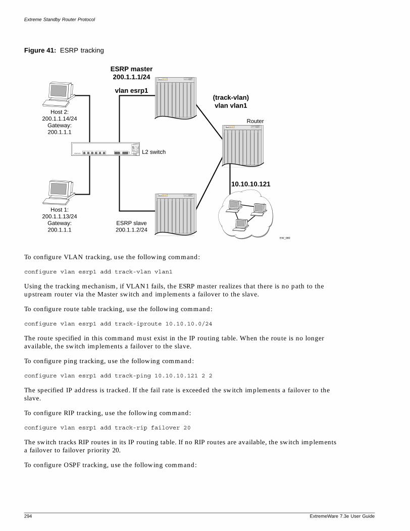
Extreme Standby Router Protocol
Figure 41: ESRP tracking
To configure VLAN tracking, use the following command:
configure vlan esrp1 add track-vlan vlan1
Using the tracking mechanism, if VLAN1 fails, the ESRP master realizes that there is no path to the upstream router via the Master switch and implements a failover to the slave.
To configure route table tracking, use the following command:
configure vlan esrp1 add track-iproute 10.10.10.0/24
The route specified in this command must exist in the IP routing table. When the route is no longer available, the switch implements a failover to the slave.
To configure ping tracking, use the following command:
configure vlan esrp1 add track-ping 10.10.10.121 2 2
The specified IP address is tracked. If the fail rate is exceeded the switch implements a failover to the slave.
To configure RIP tracking, use the following command:
configure vlan esrp1 add track-rip failover 20
The switch tracks RIP routes in its IP routing table. If no RIP routes are available, the switch implements a failover to failover priority 20.
To configure OSPF tracking, use the following command:
EW_080
ESRP master200.1.1.1/24
vlan esrp1(track-vlan)vlan vlan1
Host 2:200.1.1.14/24
Gateway:200.1.1.1
Host 1:200.1.1.13/24
Gateway:200.1.1.1
L2 switch
ESRP slave200.1.1.2/24
Router
10.10.10.121
294 ExtremeWare 7.3e User Guide

Advanced ESRP Features
ExtremeWare 7
configure vlan esrp1 add track-ospf failover 20
The switch tracks OSPF routes in its IP routing table. If no OSPF routes are available, the switch implements a failover to failover priority 20.
ESRP Port RestartYou can configure ESRP to restart ports in the ESRP master VLAN when the downstream switch is a non-Extreme switch. This action takes down and restarts the port link to clear and refresh the downstream ARP table. To configure port restart, use the following command:
configure vlan <vlan name> add ports [<portlist> | all] restart
To disable port restart, use the following command:
configure vlan <vlan name> add ports [<portlist> | all] no-restart
If a switch becomes a slave, ESRP takes down (disconnects) the physical links of member ports that have port restart enabled. The disconnection of these ports causes downstream devices to remove the ports from their FDB tables. This feature allows you to use ESRP in networks that include equipment from other vendors. After 3 seconds the ports re-establish connection with the ESRP switch.
To remove a port from the restart configuration, delete the port from the VLAN and re-add it.
NOTE
The port restart feature is also available for VRRP. For more information on VRRP, see Chapter 16.
ESRP and VLAN Aggregation
ESRP can be used to provide redundant default router protection to VLAN aggregation clients. ESRP is enabled on the super-VLAN only (not the sub-VLANs). The procedure is to add ports to the super-VLAN that is shared with the sub-VLANs. To do so, the super-VLAN should be configured with an 802.1Q tag, and added as tagged with the sub-VLAN ports to avoid a protocol conflict. Lastly, enable ESRP on the super-VLAN.
NOTE
All ports must be tagged for the super-VLAN.
The following example combines ESRP and VLAN aggregation for the super-VLAN vsuper and two sub-VLANs, v1sub and v2sub, that have ports 1 and 2 as members, respectively.
1 Create the VLANs and set up the super to sub-VLAN relationship.
create vlan v1subcreate vlan v2subcreate vlan vsuperconfigure vsuper ipaddress 10.1.2.3/24enable ipforwardingenable ospfconfigure ospf add vsuper area 0.0.0.0configure v1sub add port 1configure v2sub add port 2
.3e User Guide 295
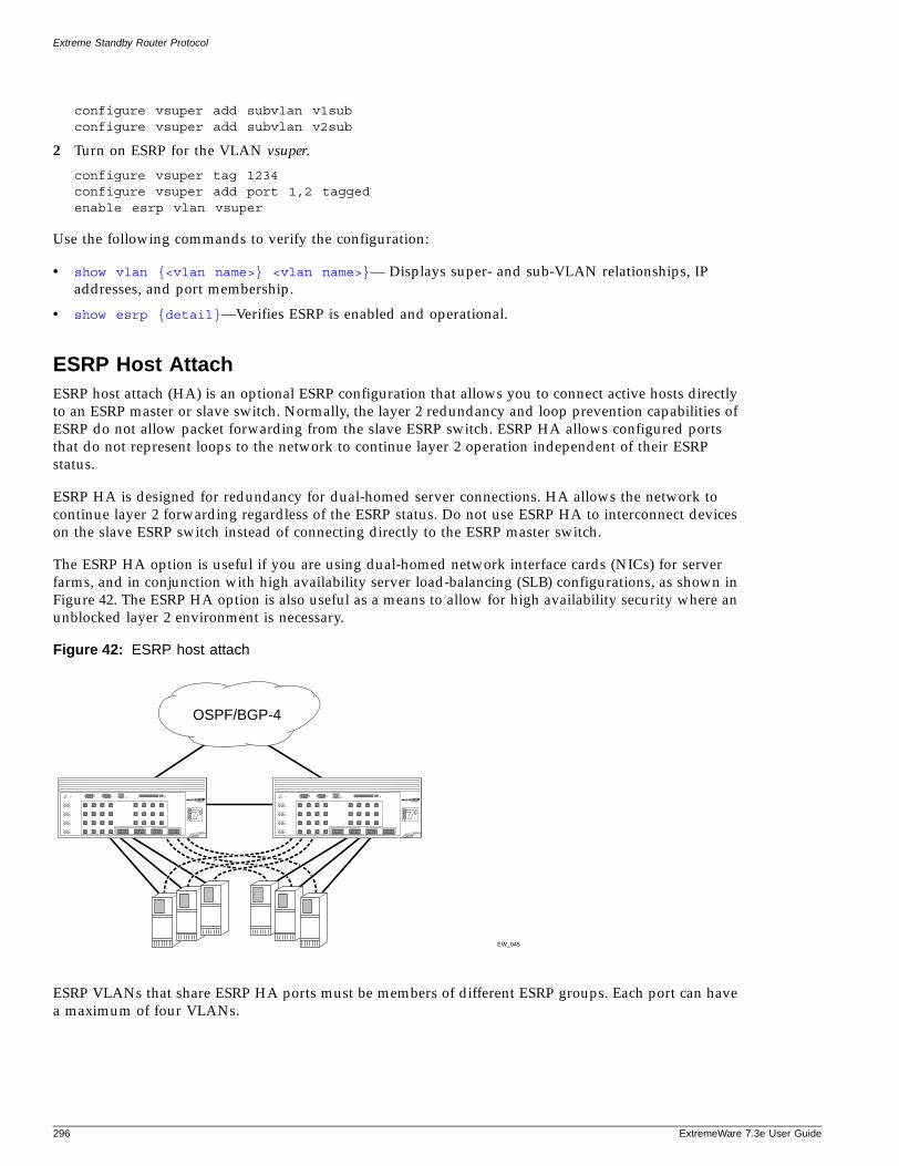
Extreme Standby Router Protocol
configure vsuper add subvlan v1subconfigure vsuper add subvlan v2sub
2 Turn on ESRP for the VLAN vsuper.
configure vsuper tag 1234configure vsuper add port 1,2 taggedenable esrp vlan vsuper
Use the following commands to verify the configuration:
• show vlan {<vlan name>} <vlan name>}— Displays super- and sub-VLAN relationships, IP addresses, and port membership.
• show esrp {detail}—Verifies ESRP is enabled and operational.
ESRP Host AttachESRP host attach (HA) is an optional ESRP configuration that allows you to connect active hosts directly to an ESRP master or slave switch. Normally, the layer 2 redundancy and loop prevention capabilities of ESRP do not allow packet forwarding from the slave ESRP switch. ESRP HA allows configured ports that do not represent loops to the network to continue layer 2 operation independent of their ESRP status.
ESRP HA is designed for redundancy for dual-homed server connections. HA allows the network to continue layer 2 forwarding regardless of the ESRP status. Do not use ESRP HA to interconnect devices on the slave ESRP switch instead of connecting directly to the ESRP master switch.
The ESRP HA option is useful if you are using dual-homed network interface cards (NICs) for server farms, and in conjunction with high availability server load-balancing (SLB) configurations, as shown in Figure 42. The ESRP HA option is also useful as a means to allow for high availability security where an unblocked layer 2 environment is necessary.
Figure 42: ESRP host attach
ESRP VLANs that share ESRP HA ports must be members of different ESRP groups. Each port can have a maximum of four VLANs.
EW_045
OSPF/BGP-4
296 ExtremeWare 7.3e User Guide
Advanced ESRP Features
ExtremeWare 7
When using load sharing with the ESRP HA feature, configure all ports in the same load-sharing group as host attach ports.
Other applications allow lower cost redundant routing configurations, because hosts can be directly attached to the switch involved with ESRP. The ESRP HA feature is used only on switches and I/O modules that have the “i” series chipset. It also requires at least one link between the master and the slave ESRP switch for carrying traffic and to exchange ESRP hello packets.
NOTE
Do not use the ESRP HA feature with the following protocols: STP, EAPS, or VRRP. A broadcast storm may occur.
ESRP Don’t CountESRP don’t count is an optional ESRP port configuration that allows the port to be part of the VLAN, but if a link failure occurs, it will not trigger a reconvergence. The don’t count feature has the effect of not counting the host ports and normal ports as active ports. This has the convenience of minimal ESRP state changes due to frequent client activities like reboots and unplugging laptops.
When using load sharing with the ESRP don’t count feature, configure all ports in the same load-sharing group as don’t count ports.
To configure don’t count on either a host attach port or a normal port, use the following command:
configure esrp port-mode [host | normal] ports <portlist> {don’t-count}
ESRP DomainsESRP domains is an optional ESRP configuration that allows you to configure multiple VLANs under the control of a single instance of the ESRP protocol. By grouping multiple VLANs under one ESRP domain, the ESRP protocol can scale to provide protection to large numbers of VLANs. All VLANs within an ESRP domain simultaneously share the same active and standby router and failover, providing one port of each member VLAN belongs to the domain master, as shown in Figure 43.
.3e User Guide 297
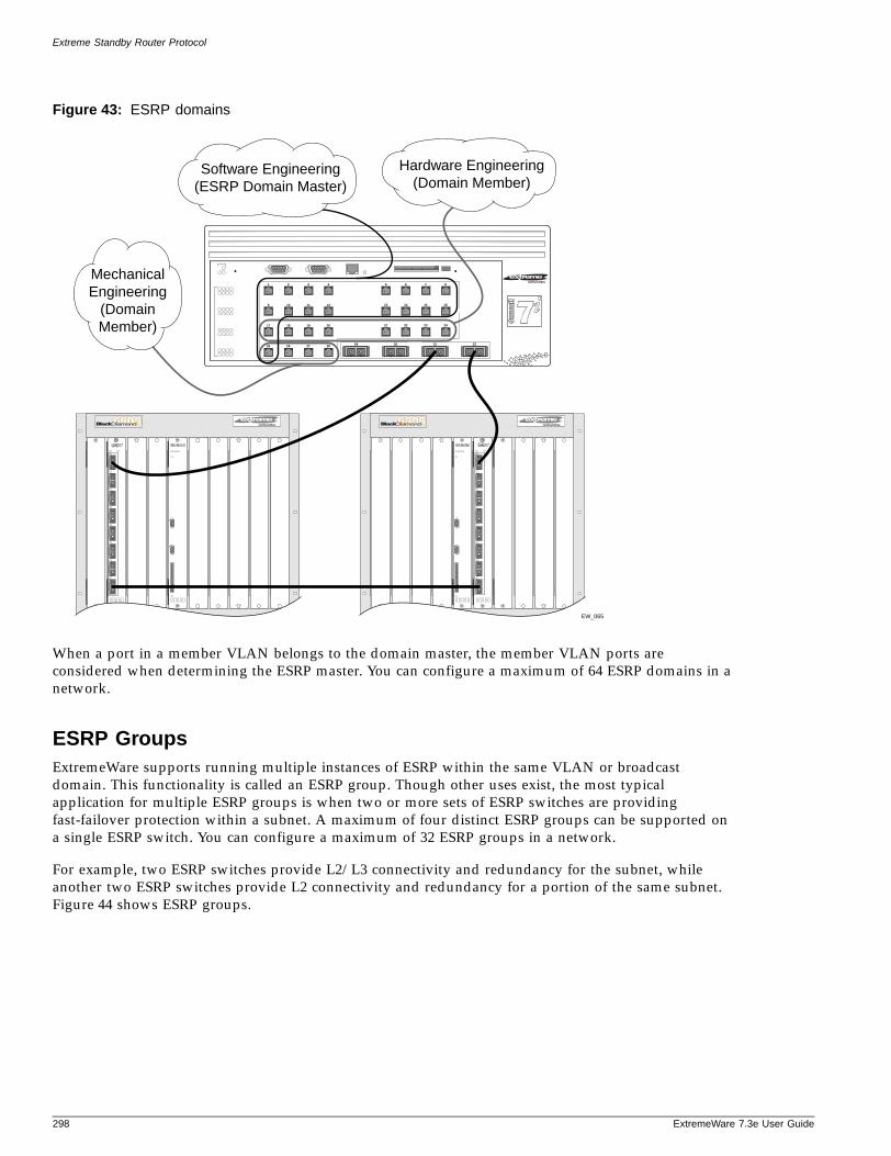
Extreme Standby Router Protocol
Figure 43: ESRP domains
When a port in a member VLAN belongs to the domain master, the member VLAN ports are considered when determining the ESRP master. You can configure a maximum of 64 ESRP domains in a network.
ESRP GroupsExtremeWare supports running multiple instances of ESRP within the same VLAN or broadcast domain. This functionality is called an ESRP group. Though other uses exist, the most typical application for multiple ESRP groups is when two or more sets of ESRP switches are providing fast-failover protection within a subnet. A maximum of four distinct ESRP groups can be supported on a single ESRP switch. You can configure a maximum of 32 ESRP groups in a network.
For example, two ESRP switches provide L2/L3 connectivity and redundancy for the subnet, while another two ESRP switches provide L2 connectivity and redundancy for a portion of the same subnet. Figure 44 shows ESRP groups.
29 30 31 32
4
12
20
5
13
21
6
14
22
7
15
23
8
16
24
28
3
11
19
27
2
10
18
26
1
9
17
25
Software Engineering(ESRP Domain Master)
MechanicalEngineering
(DomainMember)
Hardware Engineering(Domain Member)
EW_065
298 ExtremeWare 7.3e User Guide
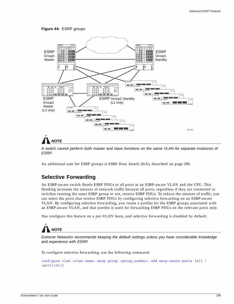
Advanced ESRP Features
ExtremeWare 7
Figure 44: ESRP groups
NOTE
A switch cannot perform both master and slave functions on the same VLAN for separate instances of ESRP.
An additional user for ESRP groups is ESRP Host Attach (HA), described on page 296.
Selective ForwardingAn ESRP-aware switch floods ESRP PDUs to all ports in an ESRP-aware VLAN and the CPU. This flooding increases the amount of network traffic because all ports, regardless if they are connected to switches running the same ESRP group or not, receive ESRP PDUs. To reduce the amount of traffic, you can select the ports that receive ESRP PDUs by configuring selective forwarding on an ESRP-aware VLAN. By configuring selective forwarding, you create a portlist for the ESRP groups associated with an ESRP-aware VLAN, and that portlist is used for forwarding ESRP PDUs on the relevant ports only.
You configure this feature on a per-VLAN basis, and selective forwarding is disabled by default.
NOTE
Extreme Networks recommends keeping the default settings unless you have considerable knowledge and experience with ESRP.
To configure selective forwarding, use the following command:
configure vlan <vlan name> esrp group <group_number> add esrp-aware-ports [all | <portlist>]
EW_056
ESRPGroup1Master
ESRPGroup2Master
(L2 only)
ESRP Group2 Standby(L2 only)
ESRPGroup1Standby
.3e User Guide 299
Extreme Standby Router Protocol
where the following is true:
• vlan name—Specifies an ESRP-aware VLAN name.
• group number—Specifies the ESRP group to which this ESRP-aware VLAN belongs. The ESRP group number must be the same as the ESRP-aware VLAN number.
• all—Specifies all of the ports to be configured. All of the ports must be connected to switches running ESRP, and the ports must connect to the ESRP master and slave switches.
• portlist—Specifies the ports to be configured. The selected ports must be connected to switches running ESRP, and the ports must connect to the ESRP master and slave switches. May be in the form 1, 2, 3-5, 2:*, 2:5, 2:6-2:8.
When an ESRP-aware switch receives an ESRP PDU, the software will lookup the group to which the PDU belongs and will forward the ESRP PDU to the group's portlist and the CPU.
You cannot enable selective forwarding on an ESRP-enabled VLAN. If you try to enable selective forwarding on an ESRP-enabled VLAN, you see the following message:
ERROR: vlan meg is esrp enabled. Cannot enable selective forwarding on esrp vlans
To disable selective forwarding, use the following command:
configure vlan <vlan name> esrp group <group_number> delete esrp-aware-ports [all | <portlist>]
where the following is true:
• group number—Specifies the ESRP group to which this ESRP-aware VLAN belongs. The ESRP group number must be the same number as the ESRP-aware VLAN.
• all—Specifies all of the ports to be disabled.
• portlist—Specifies the selected ports to be disabled.
Displaying Selective Forwarding Information
To display the ESRP-aware VLAN(s), the ESRP group(s), and the ESRP-aware port(s) that receive ESRP PDUs, use the following command:
show esrp-aware-ports {vlan <vlan name>}
Displaying ESRP Information
To verify the operational state of an ESRP VLAN and the state of its neighbor, use the following command:
show esrp {detail}
If you enter the show esrp command without a keyword, the command displays summary ESRP status information for the VLANs on the switch. Use the detail keyword to display more detailed status information.
To view tracking information about a particular VLAN, including the VLANs tracked by it and a list of the VLANs tracking it, use the following command:
show vlan
300 ExtremeWare 7.3e User Guide
Using ELRP with ESRP
ExtremeWare 7
To view ESRP configuration information for a specific VLAN, use the following command:
show esrp vlan
To view ESRP counter information for a specific VLAN, use the following command:
show esrp vlan <vlan name> {counters}
To view ESRP-aware information for a specific VLAN, including:
• Group number
• MAC address for the master of the group
• Age of the information
use the following command:
show esrp-aware vlan <vlan name>
For more information about any of the commands used to enable, disable, or configure ESRP, refer to the ExtremeWare Software Command Reference Guide.
Using ELRP with ESRP
Extreme Loop Recovery Protocol (ELRP) is a feature of ExtremeWare that allows you to prevent, detect, and recover from layer 2 loops in the network. You can use ELRP with other protocols such as ESRP.
With ELRP, each switch, except for the sender, treats the ELRP PDU as a layer 2 multicast packet. The sender uses the source and destination MAC addresses to identify the packet it sends and receives. When the sender receives its original packet back, that triggers loop detection and prevention. Once a loop is detected, the loop recovery agent is notified of the event and takes the necessary actions to recover from the loop. ELRP operates only on the sending switch; therefore, ELRP operates transparently across the network.
How a loop recovers is dependent upon the protocol that uses the loop detection services provided by ELRP. If you are using ELRP in an ESRP environment, ESRP may recover by transitioning the VLAN state from master to slave. This section describes how ESRP uses ELRP to recover from a loop and the switch behavior.
ELRP TermsTable 40 describes terms associated with ELRP.
Table 40: ELRP Terms
Term Description
Loop detection The process ELRP uses to detect a loop in the network. The switch sending the ELRP PDU waits to receive its original PDU back. If the switch receives the PDU, there is a loop in the network.
.3e User Guide 301
Extreme Standby Router Protocol
Using ELRP with ESRP to Recover LoopsELRP sends loop-detect packets to notify ESRP about loops in the network. In an ESRP environment, when the current master goes down, one of the slaves becomes the master and continues to forward layer 2 and layer 3 traffic for the ESRP VLAN. If a situation occurs when a slave incorrectly concludes that the master is down, the slave incorrectly assumes the role of master. This introduces more than one master on the VLAN which causes temporary loops and disruption in the network.
NOTE
Because ELRP introduces the pre-master state to ESRP, you must upgrade all ESRP-enabled switches within an ESRP domain to ExtremeWare 6.2.2b134 (or later) for ESRP to operate correctly. Earlier ExtremeWare releases do not recognize the pre-master state.
ELRP on ESRP Pre-Master Switch Behavior
A pre-master switch is an ESRP switch that is ready to transition to master, but is going through possible loop detection. A pre-master periodically sends out ELRP loop-detect packets (ELRP PDUs) for a specified number of times and waits to make sure that none of the sent ELRP PDUs are received. Transition to master occurs only after this additional check is completed. If any of the ELRP PDUs are received, the switch transitions from pre-master to slave state. You configure pre-master ELRP loop detection on a per VLAN basis.
ELRP on ESRP Master Switch Behavior
A master switch is an ESRP switch that sends ELRP PDUs on its VLAN ports. If the master switch receives an ELRP PDU that it sent, the master transitions to the slave. While in the slave state, the switch transitions to the pre-master state and periodically checks for loops prior to transitioning to the master. The pre-master process is described in “ELRP on ESRP Pre-Master Switch Behavior” on page 302. You configure the master ELRP loop detection on a per VLAN basis.
Configuring ELRPThis section describes the commands used to configure ELRP for use with ESRP. By default, ELRP is disabled.
Configuring the Pre-Master
If you enable the use of ELRP by ESRP in the pre-master state, ESRP requests ELRP packets sent to ensure that there is no loop in the network prior to changing to the master state. If no packets are received, there is no loop in the network. By default, the use of ELRP by ESRP in the pre-master state is disabled.
ELRP PDU Extreme Loop Recovery Protocol Protocol Data Unit. A layer 2 multicast packet that helps the sending switch determine if there is a loop in the network. The sender uses the source and destination MAC addresses to identify the packet it sends and receives. When the sender receives its original packet back, that triggers loop detection and prevention. (Also known as loop-detect packets.)
Table 40: ELRP Terms (Continued)
Term Description
302 ExtremeWare 7.3e User Guide
Using ELRP with ESRP
ExtremeWare 7
To enable the use of ELRP by ESRP in the pre-master state on a per-VLAN basis, and to configure how often and how many ELRP PDUs are sent in the pre-master state, use the following command:
configure vlan <vlan name> esrp elrp-premaster-poll enable {count <number> | interval <seconds>}
where the following is true:
• vlan name—Specifies an ESRP-enabled VLAN name.
• number—Specifies the number of times the switch sends ELRP PDUs. The default is 3, and the range is 1 to 32.
• seconds—Specifies how often, in seconds, the ELRP PDUs are sent. The default is 1 seconds, and the range is 1 to 32 seconds.
To disable the use of ELRP by ESRP in the pre-master state, use the following command:
configure vlan <vlan name> esrp elrp-premaster-poll disable
Configuring the Master
If you enable the use of ELRP by ESRP in the master state, ESRP requests that ELRP packets are periodically sent to ensure that there is no loop in the network while ESRP is in the master state. By default, the use of ELRP by ESRP in the master state is disabled.
To enable the use of ELRP by ESRP in the master state on a per-VLAN basis, and to configure how often the master checks for loops in the network, use the following command:
configure vlan <vlan name> esrp elrp-premaster-poll enable {count <number> | interval <seconds>}
where the following is true:
• vlan name—Specifies and ESRP-enabled VLAN name.
• seconds—Specifies how often, in seconds, successive ELRP packets are sent. The default is 1 second, and the range is 1 to 32 seconds.
To disable the use of ELRP by ESRP in the master state, use the following command:
configure vlan <vlan name> esrp elrp-master-poll disable
Configuring Ports
You can configure one or more ports of a VLAN where ELRP packet transmission is requested by ESRP. This allows the ports in your network that might experience loops, such as ports that connect to the master, slave, or ESRP-aware switches, to receive ELRP packets. You do not need to send ELRP packets to host ports.
By default, all ports of the VLAN where ESRP is enabled also has ELRP transmission enabled on the ports.
If you change your network configuration, and a port no longer connects to a master, slave, or ESRP-aware switch, you can disable ELRP transmission on that port. To disable ELRP transmission, use the following command:
configure vlan <vlan name> delete elrp-poll ports [<portlist> | all]
.3e User Guide 303
Extreme Standby Router Protocol
To enable ELRP transmission on a port, use the following command:
configure vlan <vlan name> add elrp-poll ports [<portlist> | all]
Displaying ELRP InformationTo display summary ELRP information, use the following command:
show elrp {<vlan name> | detail}
If you enter the show elrp command without a keyword, the command displays the total number of:
• Clients registered with ELRP
• ELRP packets transmitted
• ELRP packets received
Use the vlan name parameter to display information specific to a VLAN, and the detail keyword to display more detailed status information for VLANs in the master and pre-master states.
For more detailed information about the output associated with the show elrp command, see the ExtremeWare 7.3e Command Reference Guide.
ESRP Examples
This section provides examples of ESRP configurations.
Single VLAN Using Layer 2 and Layer 3 RedundancyThis example, shown in Figure 45, uses a number of Summit switches that perform layer 2 switching for VLAN Sales. The Summit switches are dual-homed to the BlackDiamond switches. The BlackDiamond switches perform layer 2 switching between the Summit switches and layer 3 routing to the outside world. Each Summit switch is dual-homed using active ports to two BlackDiamond switches (as many as four could be used). ESRP is enabled on each BlackDiamond switch only for the VLAN that interconnects to the Summit switches. Each BlackDiamond switch has the VLAN Sales configured using the identical IP address. The BlackDiamond switches then connect to the routed enterprise normally, using the desired routing protocol (for example RIP or OSPF).
304 ExtremeWare 7.3e User Guide
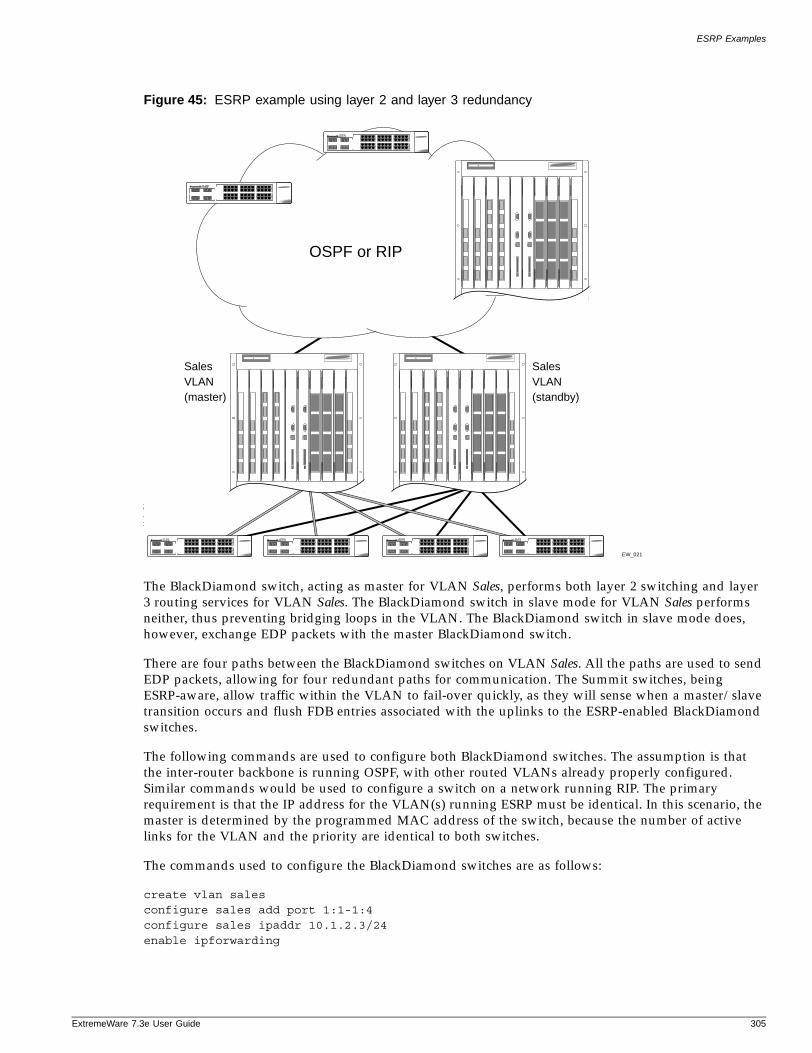
ESRP Examples
ExtremeWare 7
Figure 45: ESRP example using layer 2 and layer 3 redundancy
The BlackDiamond switch, acting as master for VLAN Sales, performs both layer 2 switching and layer 3 routing services for VLAN Sales. The BlackDiamond switch in slave mode for VLAN Sales performs neither, thus preventing bridging loops in the VLAN. The BlackDiamond switch in slave mode does, however, exchange EDP packets with the master BlackDiamond switch.
There are four paths between the BlackDiamond switches on VLAN Sales. All the paths are used to send EDP packets, allowing for four redundant paths for communication. The Summit switches, being ESRP-aware, allow traffic within the VLAN to fail-over quickly, as they will sense when a master/slave transition occurs and flush FDB entries associated with the uplinks to the ESRP-enabled BlackDiamond switches.
The following commands are used to configure both BlackDiamond switches. The assumption is that the inter-router backbone is running OSPF, with other routed VLANs already properly configured. Similar commands would be used to configure a switch on a network running RIP. The primary requirement is that the IP address for the VLAN(s) running ESRP must be identical. In this scenario, the master is determined by the programmed MAC address of the switch, because the number of active links for the VLAN and the priority are identical to both switches.
The commands used to configure the BlackDiamond switches are as follows:
create vlan salesconfigure sales add port 1:1-1:4configure sales ipaddr 10.1.2.3/24enable ipforwarding
EW_021
SalesVLAN(master)
SalesVLAN(standby)
OSPF or RIP
.3e User Guide 305
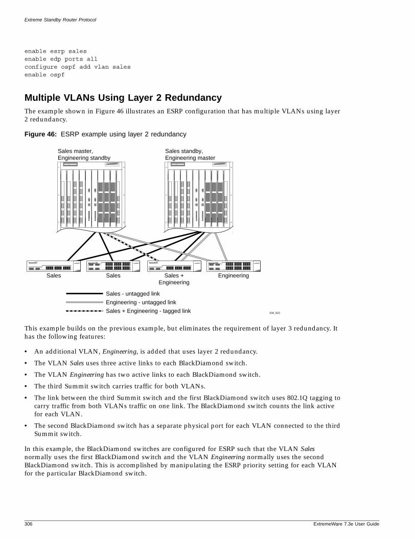
Extreme Standby Router Protocol
enable esrp salesenable edp ports allconfigure ospf add vlan salesenable ospf
Multiple VLANs Using Layer 2 RedundancyThe example shown in Figure 46 illustrates an ESRP configuration that has multiple VLANs using layer 2 redundancy.
Figure 46: ESRP example using layer 2 redundancy
This example builds on the previous example, but eliminates the requirement of layer 3 redundancy. It has the following features:
• An additional VLAN, Engineering, is added that uses layer 2 redundancy.
• The VLAN Sales uses three active links to each BlackDiamond switch.
• The VLAN Engineering has two active links to each BlackDiamond switch.
• The third Summit switch carries traffic for both VLANs.
• The link between the third Summit switch and the first BlackDiamond switch uses 802.1Q tagging to carry traffic from both VLANs traffic on one link. The BlackDiamond switch counts the link active for each VLAN.
• The second BlackDiamond switch has a separate physical port for each VLAN connected to the third Summit switch.
In this example, the BlackDiamond switches are configured for ESRP such that the VLAN Sales normally uses the first BlackDiamond switch and the VLAN Engineering normally uses the second BlackDiamond switch. This is accomplished by manipulating the ESRP priority setting for each VLAN for the particular BlackDiamond switch.
EW_022
Sales master,Engineering standby
Sales
Sales standby,Engineering master
Sales
Sales - untagged link
Sales +Engineering
Engineering
Engineering - untagged link
Sales + Engineering - tagged link
306 ExtremeWare 7.3e User Guide
ESRP Cautions
ExtremeWare 7
Configuration commands for the first BlackDiamond switch are as follows:
create vlan salesconfigure sales tag 10configure sales add port 1:1-1:2configure sales add port 1:3 taggedconfigure sales ipaddr 10.1.2.3/24create vlan engconfigure eng tag 20configure eng add port 1:4 configure eng add port 1:3 taggedconfigure eng ipaddr 10.4.5.6/24enable esrp salesenable esrp engenable edp ports allconfigure sales esrp priority 5
Configuration commands for the second BlackDiamond switch are as follows:
create vlan salesconfigure sales add port 1:1-1:3configure sales ipaddr 10.1.2.3/24create vlan engconfigure eng add port 1:4, 2:1configure eng ipaddr 10.4.5.6/24enable esrp salesenable esrp engconfigure eng esrp priority 5
ESRP Cautions
This section describes important details to be aware of when configuring ESRP.
Configuring ESRP and MultinettingWhen configuring ESRP and IP multinetting on the same switch, the parameters that affect the determination of the ESRP master must be configured identically for all the VLANs involved with IP multinetting. For example, the number of links in your configuration, the priority settings, and timer settings must be identical for all affected VLANs.
ESRP and Spanning TreeA switch running ESRP should not simultaneously participate in the Spanning Tree Protocol (STP) for the same VLAN(s). Other switches in the VLAN being protected by ESRP may run STP and the switch running ESRP forwards, but does not filter, STP BPDUs. Therefore, you can combine ESRP and STP on a network and a VLAN, but you must do so on separate devices. You should be careful to maintain ESRP connectivity between ESRP master and slave switches when you design a network that uses ESRP and STP.
.3e User Guide 307

Extreme Standby Router Protocol
308 ExtremeWare 7.3e User Guide
16 Virtual Router Redundancy Protocol
ExtremeWare 7
This chapter covers the following topics:
• Overview on page 309
• Determining the VRRP Master on page 310
• Additional VRRP Highlights on page 313
• VRRP Operation on page 314
• VRRP Configuration Parameters on page 317
• VRRP Examples on page 318
This chapter assumes that you are already familiar with the Virtual Router Redundancy Protocol (VRRP). If not, refer to the following publications for additional information:
• RFC 2338—Virtual Router Redundancy Protocol (VRRP)
• RFC 2787—Definitions of Managed Objects for the Virtual Router Redundancy Protocol
Overview
Like ESRP, VRRP is a protocol that allows multiple switches to provide redundant routing services to users. VRRP is used to eliminate the single point of failure associated with manually configuring a default gateway address on each host in a network. Without using VRRP, if the configured default gateway fails, you must reconfigure each host on the network to use a different router as the default gateway. VRRP provides a redundant path for the hosts. If the default gateway fails, the backup router assumes forwarding responsibilities.
.3e User Guide 309
Virtual Router Redundancy Protocol
VRRP Terms
Table 41 describes terms associated with VRRP.
Determining the VRRP Master
The VRRP master is determined by the following factors:
• IP address—If a router is configured with the IP address of the virtual IP address, it becomes the master.
• VRRP priority—This is a user-defined field. The range of the priority value is 1 to 254; a higher number has higher priority. The value of 255 is reserved for a router that is configured with the virtual router IP address. A value of 0 is reserved for the master router, to indicate it is releasing responsibility for the virtual router. The default value is 100.
• Higher IP address—If the routers have the same configured priority, the router with the higher IP address becomes the master.
VRRP TrackingTracking information is used to track various forms of connectivity from the VRRP router to the outside world. This section describes the following VRRP tracking options:
• VRRP VLAN tracking
• VRRP route table tracking
• VRRP ping tracking
Table 41: VRRP Terms
Term Description
virtual router A VRRP router is a group of one or more physical devices that acts as the default gateway for hosts on the network. The virtual router is identified by a virtual router identifier (VRID) and an IP address.
VRRP router Any router that is running VRRP. A VRRP router can participate in one or more virtual routers. A VRRP router can be a backup router for one more master routers.
IP address owner A single VRRP router that has the IP address of the virtual router configured as its real interface address. The IP address owner responds to TCP/IP packets addressed to the virtual router IP address. The IP address owner is optional in a VRRP configuration.
master router The physical device (router) in the virtual router that is responsible for forwarding packets sent to the virtual router, and responding to ARP requests. The master router sends out periodic advertisements that let backup routers on the network know that it is alive. If the IP address owner is identified, it always becomes the master.
backup router Any VRRP router in the virtual router that is not elected as the master. The backup router is available to assume forwarding responsibility if the master becomes unavailable.
VRID Virtual router identifier. Each virtual router is given a unique VRID. All of the VRRP routers that participate in the virtual router are assigned the same VRID.
virtual router MAC address
RFC 2338 assigns a static MAC address for the first 5 octets of the virtual router. These octets are set to 00-00-5E-00-01. When you configure the VRID, the last octet of the MAC address is dynamically assigned the VRID number.
310 ExtremeWare 7.3e User Guide
Determining the VRRP Master
ExtremeWare 7
VRRP VLAN Tracking
You can configure VRRP to track connectivity to one or more specified VLANs as criteria for failover. If no active ports remain on the specified VLANs, the router automatically relinquishes master status and remains in backup mode.
To add or delete a tracked VLAN, use one of the following commands:
configure vlan <vlan name> add track-vlan <vlan_tracked>configure vlan <vlan name> delete track-vlan <vlan_tracked>
VRRP Route Table Tracking
You can configure VRRP to track specified routes in the route table as criteria for failover. If any of the configured routes are not available within the route table, the router automatically relinquishes master status and remains in backup mode.
To add or delete a tracked route, use the following command:
configure vlan <vlan name> add track-iproute <ip address>/<masklength>
VRRP Ping Tracking
You can configure VRRP to track connectivity using a simple ping to any outside responder. The responder may represent the default route of the router, or any device meaningful to network connectivity of the master VRRP router. The router automatically relinquishes master status and remains in backup mode if a ping keepalive fails three consecutive times.
To add or delete a tracked route, use one of the following commands:
configure vlan <vlan name> add track-ping <ip address> frequency <seconds> miss <number>configure vlan <vlan name> delete track-ping <ipaddress>
To view the status of tracked devices, use the following command:
show vrrp [vlan <vlan name> | all] {detail}
.3e User Guide 311
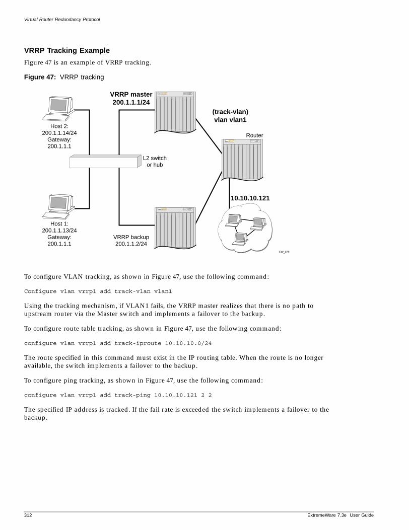
Virtual Router Redundancy Protocol
VRRP Tracking Example
Figure 47 is an example of VRRP tracking.
Figure 47: VRRP tracking
To configure VLAN tracking, as shown in Figure 47, use the following command:
Configure vlan vrrp1 add track-vlan vlan1
Using the tracking mechanism, if VLAN1 fails, the VRRP master realizes that there is no path to upstream router via the Master switch and implements a failover to the backup.
To configure route table tracking, as shown in Figure 47, use the following command:
configure vlan vrrp1 add track-iproute 10.10.10.0/24
The route specified in this command must exist in the IP routing table. When the route is no longer available, the switch implements a failover to the backup.
To configure ping tracking, as shown in Figure 47, use the following command:
configure vlan vrrp1 add track-ping 10.10.10.121 2 2
The specified IP address is tracked. If the fail rate is exceeded the switch implements a failover to the backup.
EW_079
VRRP master200.1.1.1/24
(track-vlan)vlan vlan1
Host 2:200.1.1.14/24
Gateway:200.1.1.1
Host 1:200.1.1.13/24
Gateway:200.1.1.1
L2 switchor hub
VRRP backup200.1.1.2/24
Router
10.10.10.121
312 ExtremeWare 7.3e User Guide
Additional VRRP Highlights
ExtremeWare 7
Electing the Master Router
VRRP uses an election algorithm to dynamically assign responsibility for the master router to one of the VRRP routers on the network. A VRRP router is elected master if one of the following is true:
• The router is the IP address owner.
• The router is configured with the highest priority (the range is 3 - 255).
If the master router becomes unavailable, the election process provides dynamic failover and the backup router that has the highest priority assumes the role of master.
A new master is elected when one of the following things happen:
• VRRP is disabled on the master router.
• Loss of communication between master and backup router(s).
When VRRP is disabled on the master interface, the master router sends an advertisement with the priority set to 0 to all backup routers. This signals the backup routers that they do not need to wait for the master down interval to expire, and the master election process for a new master can begin immediately.
The master down interval is set as follows:
3 * advertisement interval + skew time
Where:
• The advertisement interval is a user-configurable option.
• The skew time is (256-priority/256).
NOTE
An extremely busy CPU can create a short dual master situation. To avoid this, increase the advertisement interval.
Additional VRRP Highlights
The following additional points pertain to VRRP:
• VRRP packets are encapsulated IP packets.
• The VRRP multicast address is 224.0.0.18.
• The virtual router MAC address is 00 00 5E 00 01 <vrid>
• Duplicate virtual router IDs are allowed on the router, but not on the same interface.
• The maximum number of supported VRIDs per interface is 4.
• An interconnect link between VRRP routers should not be used, except when VRRP routers have hosts directly attached.
• A maximum of 64 VRID instances are supported on the router.
• Up to 4 unique VRIDs can be configured on the router. VRIDs can be re-used, but not on the same interface.
.3e User Guide 313
Virtual Router Redundancy Protocol
• VRRP and Spanning Tree can be simultaneously enabled on the same switch.
• VRRP and ESRP cannot be simultaneously enabled on the same switch.
VRRP Port RestartYou can configure VRRP to restart ports if those ports are members of a VLAN that becomes a backup. To configure port restart, use the following command:
configure vlan <vlan name> add ports [<portlist> | all] restart
To disable port restart, use the following command:
configure vlan <vlan name> add ports [<portlist> | all] no-restart
If a VLAN becomes a backup, VRRP disconnects member ports that have port restart enabled. The disconnection of these ports causes downstream devices to remove the ports from their FDB tables. This feature allows you to use VRRP in networks that include equipment from other vendors. After 3 seconds the ports re-establish connection with the VRRP switch.
To remove a port from the restart configuration, delete the port from the VLAN and re-add it.
NOTE
The port restart feature is also available for ESRP. For more information on ESRP, see Chapter 15.
VRRP Operation
This section describes two VRRP network configuration:
• A simple VRRP network
• A fully-redundant VRRP network
Simple VRRP Network ConfigurationFigure 48 shows a simple VRRP network.
314 ExtremeWare 7.3e User Guide
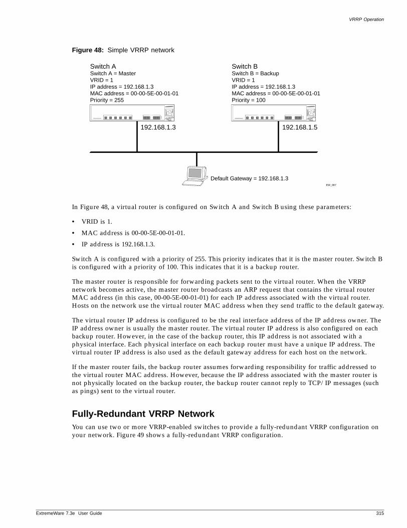
VRRP Operation
ExtremeWare 7
Figure 48: Simple VRRP network
In Figure 48, a virtual router is configured on Switch A and Switch B using these parameters:
• VRID is 1.
• MAC address is 00-00-5E-00-01-01.
• IP address is 192.168.1.3.
Switch A is configured with a priority of 255. This priority indicates that it is the master router. Switch B is configured with a priority of 100. This indicates that it is a backup router.
The master router is responsible for forwarding packets sent to the virtual router. When the VRRP network becomes active, the master router broadcasts an ARP request that contains the virtual router MAC address (in this case, 00-00-5E-00-01-01) for each IP address associated with the virtual router. Hosts on the network use the virtual router MAC address when they send traffic to the default gateway.
The virtual router IP address is configured to be the real interface address of the IP address owner. The IP address owner is usually the master router. The virtual router IP address is also configured on each backup router. However, in the case of the backup router, this IP address is not associated with a physical interface. Each physical interface on each backup router must have a unique IP address. The virtual router IP address is also used as the default gateway address for each host on the network.
If the master router fails, the backup router assumes forwarding responsibility for traffic addressed to the virtual router MAC address. However, because the IP address associated with the master router is not physically located on the backup router, the backup router cannot reply to TCP/IP messages (such as pings) sent to the virtual router.
Fully-Redundant VRRP NetworkYou can use two or more VRRP-enabled switches to provide a fully-redundant VRRP configuration on your network. Figure 49 shows a fully-redundant VRRP configuration.
EW_067
Switch ASwitch A = MasterVRID = 1IP address = 192.168.1.3MAC address = 00-00-5E-00-01-01Priority = 255
Default Gateway = 192.168.1.3
192.168.1.3
Switch BSwitch B = BackupVRID = 1IP address = 192.168.1.3MAC address = 00-00-5E-00-01-01Priority = 100
192.168.1.5
.3e User Guide 315
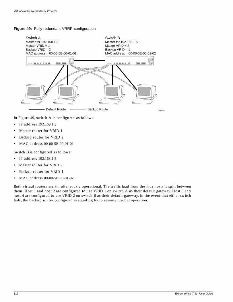
Virtual Router Redundancy Protocol
Figure 49: Fully-redundant VRRP configuration
In Figure 49, switch A is configured as follows:
• IP address 192.168.1.3
• Master router for VRID 1
• Backup router for VRID 2
• MAC address 00-00-5E-00-01-01
Switch B is configured as follows:
• IP address 192.168.1.5
• Master router for VRID 2
• Backup router for VRID 1
• MAC address 00-00-5E-00-01-02
Both virtual routers are simultaneously operational. The traffic load from the four hosts is split between them. Host 1 and host 2 are configured to use VRID 1 on switch A as their default gateway. Host 3 and host 4 are configured to use VRID 2 on switch B as their default gateway. In the event that either switch fails, the backup router configured is standing by to resume normal operation.
EW_068Default Route
Switch AMaster for 192.168.1.3Master VRID = 1Backup VRID = 2MAC address = 00-00-5E-00-01-01
Switch BMaster for 192.168.1.5Master VRID = 2Backup VRID = 1MAC address = 00-00-5E-00-01-02
Backup Route
316 ExtremeWare 7.3e User Guide
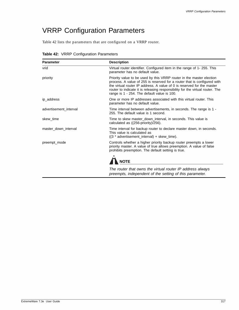
VRRP Configuration Parameters
ExtremeWare 7
VRRP Configuration Parameters
Table 42 lists the parameters that are configured on a VRRP router.
Table 42: VRRP Configuration Parameters
Parameter Description
vrid Virtual router identifier. Configured item in the range of 1- 255. This parameter has no default value.
priority Priority value to be used by this VRRP router in the master election process. A value of 255 is reserved for a router that is configured with the virtual router IP address. A value of 0 is reserved for the master router to indicate it is releasing responsibility for the virtual router. The range is 1 - 254. The default value is 100.
ip_address One or more IP addresses associated with this virtual router. This parameter has no default value.
advertisement_interval Time interval between advertisements, in seconds. The range is 1 - 255. The default value is 1 second.
skew_time Time to skew master_down_interval, in seconds. This value is calculated as ((256-priority)/256).
master_down_interval Time interval for backup router to declare master down, in seconds. This value is calculated as ((3 * advertisement_interval) + skew_time).
preempt_mode Controls whether a higher priority backup router preempts a lower priority master. A value of true allows preemption. A value of false prohibits preemption. The default setting is true.
NOTE
The router that owns the virtual router IP address always preempts, independent of the setting of this parameter.
.3e User Guide 317
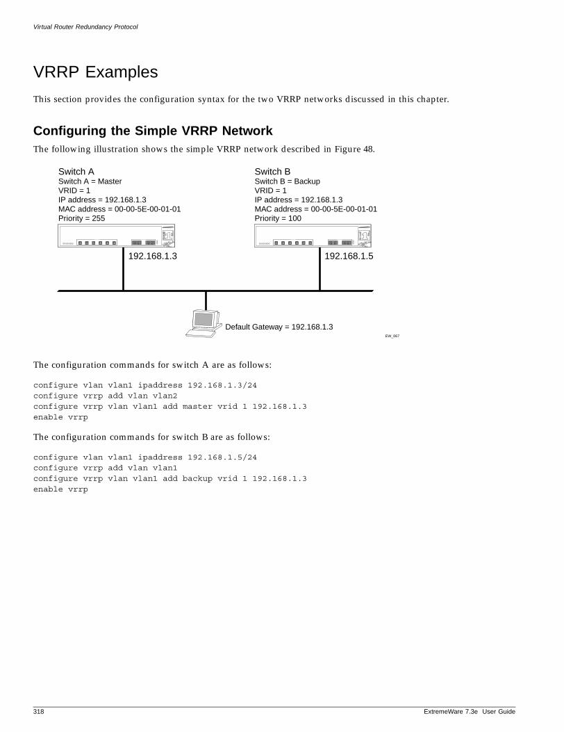
Virtual Router Redundancy Protocol
VRRP Examples
This section provides the configuration syntax for the two VRRP networks discussed in this chapter.
Configuring the Simple VRRP NetworkThe following illustration shows the simple VRRP network described in Figure 48.
The configuration commands for switch A are as follows:
configure vlan vlan1 ipaddress 192.168.1.3/24configure vrrp add vlan vlan2configure vrrp vlan vlan1 add master vrid 1 192.168.1.3enable vrrp
The configuration commands for switch B are as follows:
configure vlan vlan1 ipaddress 192.168.1.5/24configure vrrp add vlan vlan1configure vrrp vlan vlan1 add backup vrid 1 192.168.1.3enable vrrp
EW_067
Switch ASwitch A = MasterVRID = 1IP address = 192.168.1.3MAC address = 00-00-5E-00-01-01Priority = 255
Default Gateway = 192.168.1.3
192.168.1.3
Switch BSwitch B = BackupVRID = 1IP address = 192.168.1.3MAC address = 00-00-5E-00-01-01Priority = 100
192.168.1.5
318 ExtremeWare 7.3e User Guide
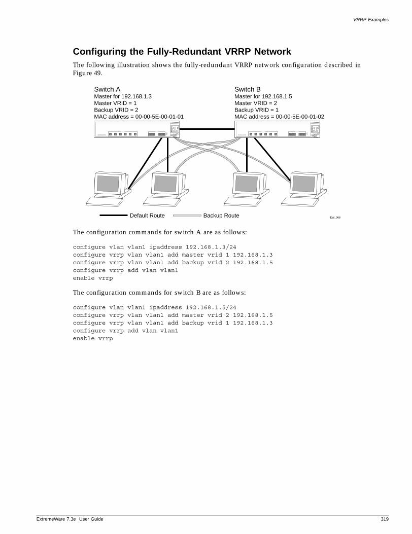
VRRP Examples
ExtremeWare 7
Configuring the Fully-Redundant VRRP NetworkThe following illustration shows the fully-redundant VRRP network configuration described in Figure 49.
The configuration commands for switch A are as follows:
configure vlan vlan1 ipaddress 192.168.1.3/24configure vrrp vlan vlan1 add master vrid 1 192.168.1.3configure vrrp vlan vlan1 add backup vrid 2 192.168.1.5configure vrrp add vlan vlan1enable vrrp
The configuration commands for switch B are as follows:
configure vlan vlan1 ipaddress 192.168.1.5/24configure vrrp vlan vlan1 add master vrid 2 192.168.1.5configure vrrp vlan vlan1 add backup vrid 1 192.168.1.3configure vrrp add vlan vlan1enable vrrp
EW_068Default Route
Switch AMaster for 192.168.1.3Master VRID = 1Backup VRID = 2MAC address = 00-00-5E-00-01-01
Switch BMaster for 192.168.1.5Master VRID = 2Backup VRID = 1MAC address = 00-00-5E-00-01-02
Backup Route
.3e User Guide 319

Virtual Router Redundancy Protocol
320 ExtremeWare 7.3e User Guide
17 IP Unicast Routing
ExtremeWare 7
This chapter describes the following topics:
• Overview of IP Unicast Routing on page 321
• Proxy ARP on page 324
• Relative Route Priorities on page 325
• Configuring IP Unicast Routing on page 326
• Routing Configuration Example on page 327
• Configuring DHCP/BOOTP Relay on page 329
• UDP-Forwarding on page 331
This chapter assumes that you are already familiar with IP unicast routing. If not, refer to the following publications for additional information:
• RFC 1256—ICMP Router Discovery Messages
• RFC 1812—Requirements for IP Version 4 Routers
NOTE
For more information on interior gateway protocols, see Chapter 13.
Overview of IP Unicast Routing
The switch provides full layer 3, IP unicast routing. It exchanges routing information with other routers on the network using either the Routing Information Protocol (RIP) or the Open Shortest Path First (OSPF) protocol. The switch dynamically builds and maintains a routing table, and determines the best path for each of its routes.
Each host using the IP unicast routing functionality of the switch must have a unique IP address assigned. In addition, the default gateway assigned to the host must be the IP address of the router interface.
.3e User Guide 321
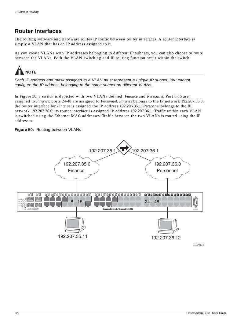
IP Unicast Routing
Router InterfacesThe routing software and hardware routes IP traffic between router interfaces. A router interface is simply a VLAN that has an IP address assigned to it.
As you create VLANs with IP addresses belonging to different IP subnets, you can also choose to route between the VLANs. Both the VLAN switching and IP routing function occur within the switch.
NOTE
Each IP address and mask assigned to a VLAN must represent a unique IP subnet. You cannot configure the IP address belonging to the same subnet on different VLANs.
In Figure 50, a switch is depicted with two VLANs defined; Finance and Personnel. Port 8-15 are assigned to Finance; ports 24-48 are assigned to Personnel. Finance belongs to the IP network 192.207.35.0; the router interface for Finance is assigned the IP address 192.206.35.1. Personnel belongs to the IP network 192.207.36.0; its router interface is assigned IP address 192.207.36.1. Traffic within each VLAN is switched using the Ethernet MAC addresses. Traffic between the two VLANs is routed using the IP addresses.
Figure 50: Routing between VLANs
ES4K024
Finance Personnel192.207.36.0192.207.35.0
192.207.36.1192.207.35.1
8 - 15 24 - 48
192.207.35.11 192.207.36.12
322 ExtremeWare 7.3e User Guide
Overview of IP Unicast Routing
ExtremeWare 7
Populating the Routing Table The switch maintains an IP routing table for both network routes and host routes. The table is populated from the following sources:
• Dynamically, by way of routing protocol packets or by ICMP redirects exchanged with other routers
• Statically, by way of routes entered by the administrator
— Default routes, configured by the administrator
— Locally, by way of interface addresses assigned to the system
— By other static routes, as configured by the administrator
NOTE
If you define a default route, and subsequently delete the VLAN on the subnet associated with the default route, the invalid default route entry remains. You must manually delete the configured default route.
Dynamic Routes
Dynamic routes are typically learned by way of RIP or OSPF. Routers that use RIP or OSPF exchange information in their routing tables in the form of advertisements. Using dynamic routes, the routing table contains only networks that are reachable.
Dynamic routes are aged out of the table when an update for the network is not received for a period of time, as determined by the routing protocol.
Static Routes
Static routes are manually entered into the routing table. Static routes are used to reach networks not advertised by routers.
Static routes can also be used for security reasons, to control which routes you want advertised by the router. You can decide if you want all static routes to be advertised, using one of the following commands:
• enable rip exportstatic or disable rip exportstatic
• enable ospf export direct [cost <metric> [ase-type-1 | ase-type-2] {tag <number>}
| <route map>] or disable ospf export [direct | rip | static]
The default setting is disabled. Static routes are never aged out of the routing table.
A static route must be associated with a valid IP subnet. An IP subnet is associated with a single VLAN by its IP address and subnet mask. If the VLAN is subsequently deleted, the static route entries using that subnet must be deleted manually.
Multiple Routes
When there are multiple, conflicting choices of a route to a particular destination, the router picks the route with the longest matching network mask. If these are still equal, the router picks the route using the following criteria (in the order specified):
• Directly attached network interfaces
• ICMP redirects
.3e User Guide 323
IP Unicast Routing
• Static routes
• Directly attached network interfaces that are not active.
NOTE
If you define multiple default routes, the route that has the lowest metric is used. If multiple default routes have the same lowest metric, the system picks one of the routes.
You can also configure blackhole routes—traffic to these destinations is silently dropped.
IP Route Sharing
IP route sharing allows multiple equal-cost routes to be used concurrently. IP route sharing can be used with static routes or with OSPF routes. In OSPF, this capability is referred to as equal cost multipath (ECMP) routing. To use IP route sharing, use the following command:
enable iproute sharing
Next, configure static routes and/or OSPF as you would normally. ExtremeWare supports unlimited route sharing across static routes and up to 12 ECMP routes for OSPF.
Route sharing is useful only in instances where you are constrained for bandwidth. This is typically not the case using Extreme switches. Using route sharing makes router troubleshooting more difficult because of the complexity in predicting the path over which the traffic will travel.
Subnet-Directed Broadcast ForwardingYou can enable or disable the hardware forwarding of subnet-directed broadcast IP packets. This allows the switch to forward subnet-directed broadcast packets at wire-speed.
To enable or disable hardware forwarding, use one the following commands:
[enable | disable] ipforwarding [vlan <vlan_name>]
The entries are added to the IP forwarding table as standard entries and you can view them using the show ipfdb command.
You can also configure the VLAN router interface to either forward and process all subnet-directed broadcast packets, or to simply forward these packets after they have been added to the IP forwarding database. The latter option allows you to improve CPU forwarding performance by having upper layers, such as UDP and TCP, ignore broadcast packet processing (for example, if the packets have IP-options configured).
To enable or disable broadcast packet processing, use the following command:
[enable | disable] ipforwarding ignore-broadcast vlan <vlan_name>
Using these commands together, you can achieve a 100% reduction on the Summit switches.
Proxy ARP
Proxy Address Resolution Protocol (ARP) was first invented so that ARP-capable devices could respond to ARP Request packets on behalf of ARP-incapable devices. Proxy ARP can also be used to achieve
324 ExtremeWare 7.3e User Guide
Relative Route Priorities
ExtremeWare 7
router redundancy and simplify IP client configuration. The switch supports proxy ARP for this type of network configuration. The section describes some example of how to use proxy ARP with the switch.
ARP-Incapable DevicesTo configure the switch to respond to ARP Requests on behalf of devices that are incapable of doing so, you must configure the IP address and MAC address of the ARP-incapable device using the use the following command:
configure iparp add proxy <ip address> {<mask>} {<mac_address>} {always}
Once configured, the system responds to ARP Requests on behalf of the device as long as the following conditions are satisfied:
• The valid IP ARP Request is received on a router interface.
• The target IP address matches the IP address configured in the proxy ARP table.
• The proxy ARP table entry indicates that the system should always answer this ARP Request, regardless of the ingress VLAN (the always parameter must be applied).
Once all the proxy ARP conditions are met, the switch formulates an ARP Response using the configured MAC address in the packet.
Proxy ARP Between SubnetsIn some networks, it is desirable to configure the IP host with a wider subnet than the actual subnet mask of the segment. Proxy ARP can be used so that the router answers ARP Requests for devices outside of the subnet. As a result, the host communicates as if all devices are local. In reality, communication with devices outside of the subnet are proxied by the router.
For example, an IP host is configured with a class B address of 100.101.102.103 and a mask of 255.255.0.0. The switch is configured with the IP address 100.101.102.1 and a mask of 255.255.255.0. The switch is also configured with a proxy ARP entry of IP address 100.101.0.0 and mask 255.255.0.0, without the always parameter.
When the IP host tries to communicate with the host at address 100.101.45.67, the IP hosts communicates as if the two hosts are on the same subnet, and sends out an IP ARP Request. The switch answers on behalf of the device at address 100.101.45.67, using its own MAC address. All subsequent data packets from 100.101.102.103 are sent to the switch, and the switch routes the packets to 100.101.45.67.
Relative Route Priorities
Table 43 lists the relative priorities assigned to routes depending upon the learned source of the route.
NOTE
Although these priorities can be changed, do not attempt any manipulation unless you are expertly familiar with the possible consequences.
.3e User Guide 325
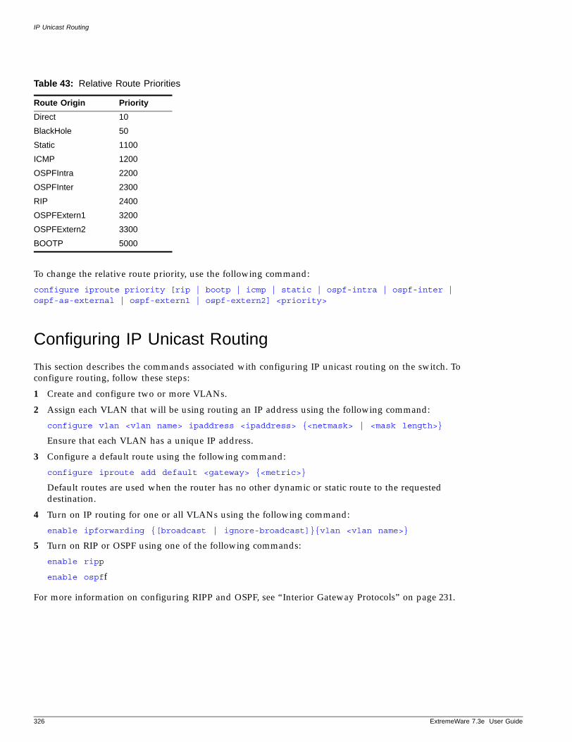
IP Unicast Routing
To change the relative route priority, use the following command:
configure iproute priority [rip | bootp | icmp | static | ospf-intra | ospf-inter | ospf-as-external | ospf-extern1 | ospf-extern2] <priority>
Configuring IP Unicast Routing
This section describes the commands associated with configuring IP unicast routing on the switch. To configure routing, follow these steps:
1 Create and configure two or more VLANs.
2 Assign each VLAN that will be using routing an IP address using the following command:
configure vlan <vlan name> ipaddress <ipaddress> {<netmask> | <mask length>}
Ensure that each VLAN has a unique IP address.
3 Configure a default route using the following command:
configure iproute add default <gateway> {<metric>}
Default routes are used when the router has no other dynamic or static route to the requested destination.
4 Turn on IP routing for one or all VLANs using the following command:
enable ipforwarding {[broadcast | ignore-broadcast]}{vlan <vlan name>}
5 Turn on RIP or OSPF using one of the following commands:
enable ripp
enable ospff
For more information on configuring RIPP and OSPF, see “Interior Gateway Protocols” on page 231.
Table 43: Relative Route Priorities
Route Origin Priority
Direct 10
BlackHole 50
Static 1100
ICMP 1200
OSPFIntra 2200
OSPFInter 2300
RIP 2400
OSPFExtern1 3200
OSPFExtern2 3300
BOOTP 5000
326 ExtremeWare 7.3e User Guide
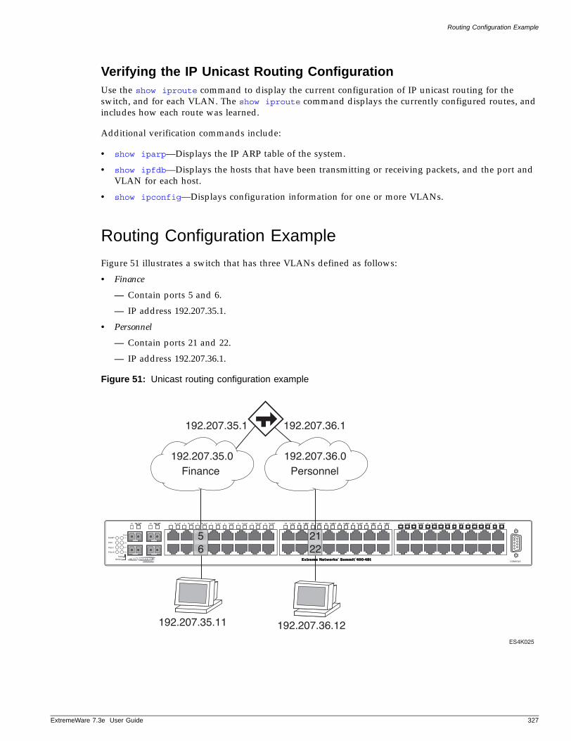
Routing Configuration Example
ExtremeWare 7
Verifying the IP Unicast Routing ConfigurationUse the show iproute command to display the current configuration of IP unicast routing for the switch, and for each VLAN. The show iproute command displays the currently configured routes, and includes how each route was learned.
Additional verification commands include:
• show iparp—Displays the IP ARP table of the system.
• show ipfdb—Displays the hosts that have been transmitting or receiving packets, and the port and VLAN for each host.
• show ipconfig—Displays configuration information for one or more VLANs.
Routing Configuration Example
Figure 51 illustrates a switch that has three VLANs defined as follows:
• Finance
— Contain ports 5 and 6.
— IP address 192.207.35.1.
• Personnel
— Contain ports 21 and 22.
— IP address 192.207.36.1.
Figure 51: Unicast routing configuration example
ES4K025
Finance Personnel192.207.36.0192.207.35.0
192.207.36.1192.207.35.1
56
2122
192.207.35.11 192.207.36.12
.3e User Guide 327
IP Unicast Routing
In this configuration, all IP traffic from stations connected to ports 5 and 6 have access to the switch by way of the VLAN Finance. Ports 21 and 22 reach the switch by way of the VLAN Personnel..
The example in Figure 51 is configured as follows:
create vlan Financecreate vlan Personnel
config Finance add port 5,6config Personnel add port 21,22
config Finance ipaddress 192.207.35.1config Personnel ipaddress 192.207.36.1
config rip add vlan Financeconfig rip add vlan Personnel
enable ipforwardingenable rip
ICMP Packet ProcessingAs ICMP packets are routed or generated, you can take various actions to control distribution. For ICMP packets typically generated or observed as part of the routing function, you can assert control on a per-type, per-VLAN basis. You would alter the default settings for security reasons: to restrict the success of tools that can be used to find an important application, host, or topology information. The controls include the disabling of transmitting ICMP messages associated with unreachables, port-unreachables, time-exceeded, parameter-problems, redirects, time-stamp, and address-mask requests.
To enable or disable the generation of an ICMP address-mask reply on one or all VLANs, use the following commands:
enable icmp address-mask {vlan <vlan name>}
disable icmp address-mask {vlan <vlan name>}
To enable or disable the generation of an ICMP parameter-problem message on one or all VLANs, use the following commands:
enable icmp parameter-problem {vlan <vlan name>}
disable icmp parameter-problem {vlan <vlan name>}
To enable or disable the generation of ICMP port unreachable messages on one or all VLANs, use the following commands:
enable icmp port-unreachables {vlan <vlan name>}
disable icmp port-unreachables {vlan <vlan name>}
To enable or disable the generation of ICMP redirect messages on one or all VLANs, use the following commands:
enable icmp redirects {vlan <vlan name>}
disable icmp redirects {vlan <vlan name>}
328 ExtremeWare 7.3e User Guide
Configuring DHCP/BOOTP Relay
ExtremeWare 7
To enable or disable the generation of ICMP time exceeded messages on one or all VLANs, use the following commands:
enable icmp time-exceeded {vlan <vlan name>}
disable icmp time-exceeded {vlan <vlan name>}
To enable or disable the generation of an ICMP timestamp response on one or all VLANs, use the following commands:
enable icmp timestamp {vlan <vlan name>}
disable icmp timestamp {vlan <vlan name>}
To enable or disable the generation of ICMP unreachable messages on one or all VLANs, use the following commands:
enable icmp unreachables {vlan <vlan name>}
disable icmp unreachables {vlan <vlan name>}
To enable or disable the modification of route table information when an ICMP redirect message is received, use the following commands:
enable icmp useredirects
disable icmp useredirects
To reset all of the ICMP settings to the default values, use the following command:
unconfigure icmp
For ICMP packets that are typically routed, you can apply access lists to restrict forwarding behavior. Access lists are described in Chapter 10.
Configuring DHCP/BOOTP Relay
Once IP unicast routing is configured, you can configure the switch to forward Dynamic Host Configuration Protocol (DHCP) or BOOTP requests coming from clients on subnets being serviced by the switch and going to hosts on different subnets. This feature can be used in various applications, including DHCP services between Windows NT servers and clients running Windows 95. To configure the relay function, follow these steps:
1 Configure VLANs and IP unicast routing.
2 Enable the DHCP or BOOTP relay function, using the following command:
enable bootprelay
3 Configure the addresses to which DHCP or BOOTP requests should be directed, using the following command:
configure bootprelay add <ip address>
To delete a BOOTP relay entry, use the following command:
configure bootprelay delete [<ip address> | all]
.3e User Guide 329
IP Unicast Routing
Configuring the DHCP Relay Agent Option (Option 82)After configuring and enabling the DHCP/BOOTP relay feature, you can enable the DHCP relay agent option feature. This feature inserts a piece of information, called option 82, into any DHCP request packet that is to be relayed by the switch. Similarly, if a DHCP reply received by the switch contains a valid relay agent option, the option will be stripped from the packet before it is relayed to the client.
The DHCP relay agent option consists of two pieces of data, called sub-options. The first is the agent circuit ID sub-option, and the second is the agent remote ID sub-option. When the DHCP relay agent option is enabled on switches running ExtremeWare, the value of these sub-options is set as follows:
• Agent circuit ID sub-option: Contains the ID of the port on which the original DHCP request packet was received. This ID is encoded as (port_number). For example, if the DHCP request were received on port 12, the agent circuit ID value would be 3012. On non-slot-based switches, the agent circuit ID value is simply the port number.
• Agent remote ID sub-option: Always contains the Ethernet MAC address of the relaying switch. You can display the Ethernet MAC address of the switch by issuing the show switch command.
To enable the DHCP relay agent option, use the following command after configuring the DHCP/BOOTP relay function:
configure bootprelay dhcp-agent information option
To disable the DHCP relay agent option, use the following command:
unconfigure bootprelay dhcp-agent information option
In some instances, a DHCP server may not properly handle a DHCP request packet containing a relay agent option. To prevent DHCP reply packets with invalid or missing relay agent options from being forwarded to the client, use the following command:
configure bootprelay dhcp-agent information check
To disable checking of DHCP replies, use this command:
unconfigure bootprelay dhcp-agent information check
A DHCP relay agent may receive a client DHCP packet that has been forwarded from another relay agent. If this relayed packet already contains a relay agent option, then the switch will handle this packet according to the configured DHCP relay agent option policy. To configure this policy, use the following command:
configure bootprelay dhcp-agent information policy <policy>
where <policy> must be one of the following values: replace, keep, or drop. The default relay policy is replace. To configure the policy to the default, use this command:
unconfigure bootprelay dhcp-agent information policy
For more general information about the DHCP relay agent information option, refer to RFC 3046.
Verifying the DHCP/BOOTP Relay ConfigurationTo verify the DHCP/BOOTP relay configuration, use the following command:
show ipconfig
330 ExtremeWare 7.3e User Guide
UDP-Forwarding
ExtremeWare 7
This command displays the configuration of the BOOTP relay service, and the addresses that are currently configured.
UDP-Forwarding
UDP-forwarding is a flexible and generalized routing utility for handling the directed forwarding of broadcast UDP packets. UDP-forwarding allows applications, such as multiple DHCP relay services from differing sets of VLANs, to be directed to different DHCP servers. The following rules apply to UDP broadcast packets handled by this feature:
• If the UDP profile includes BOOTP or DHCP, it is handled according to guidelines in RFC 1542.
• If the UDP profile includes other types of traffic, these packets have the IP destination address modified as configured, and changes are made to the IP and UDP checksums and decrements to the TTL field, as appropriate.
If the UDP-forwarding is used for BOOTP or DHCP forwarding purposes, do not configure or use the existing bootprelay function. However, if the previous bootprelay functions are adequate, you may continue to use them.
NOTE
UDP-forwarding only works across a layer 3 boundary.
Configuring UDP-ForwardingTo configure UDP-forwarding, the first thing you must do is create a UDP-forward destination profile. The profile describes the types of UDP packets (by port number) that are used, and where they are to be forwarded. You must give the profile a unique name, in the same manner as a VLAN, protocol filter, or Spanning Tree Domain.
Next, configure a VLAN to make use of the UDP-forwarding profile. As a result, all incoming traffic from the VLAN that matches the UDP profile is handled as specified in the UDP-forwarding profile.
A maximum of ten UDP-forwarding profiles can be defined. Each named profile may contain a maximum of eight “rules” defining the UDP port, and destination IP address or VLAN. A VLAN can make use of a single UDP-forwarding profile. UDP packets directed toward a VLAN use an all-ones broadcast on that VLAN.
UDP-Forwarding ExampleIn this example, the VLAN Marketing and the VLAN Operations are pointed toward a specific backbone DHCP server (with IP address 10.1.1.1) and a backup server (with IP address 10.1.1.2). Additionally, the VLAN LabUser is configured to use any responding DHCP server on a separate VLAN called LabSvrs.
The commands for this configuration are as follows:
create udp-profile backbonedhcpcreate udp-profile labdhcpconfigure backbonedhcp add 67 ipaddress 10.1.1.1configure backbonedhcp add 67 ipaddress 10.1.1.2configure labdhcp add 67 vlan labsvrs
.3e User Guide 331
IP Unicast Routing
configure marketing udp-profile backbonedhcpconfigure operations udp-profile backbonedhcpconfigure labuser udp-profile labdhcp
UDP Echo ServerYou can use UDP Echo packets to measure the transit time for data between the transmitting and receiving end.
To enable UDP echo server support, use the following command:
enable udp-echo-server
To disable UDP echo server support, use the following command:
disable udp-echo-server
332 ExtremeWare 7.3e User Guide
18 Interior Gateway Protocols
ExtremeWare 7
This chapter describes the following topics:
• Overview on page 334
• Overview of RIP on page 335
• Overview of OSPF on page 336
• Route Re-Distribution on page 342
• RIP Configuration Example on page 343
• Configuring OSPF on page 344
• OSPF Configuration Example on page 345
• Displaying OSPF Settings on page 347
This chapter assumes that you are already familiar with IP unicast routing. If not, refer to the following publications for additional information:
• RFC 1058—Routing Information Protocol (RIP)
• RFC 1723—RIP Version 2
• RFC 2178—OSPF Version 2
• Interconnections: Bridges and Routers by Radia PerlmanISBN 0-201-56332-0Published by Addison-Wesley Publishing Company
.3e User Guide 333
Interior Gateway Protocols
Overview
The switch supports the use of two interior gateway protocols (IGPs); the Routing Information Protocol (RIP) and the Open Shortest Path First (OSPF) protocol.
RIP is a distance-vector protocol, based on the Bellman-Ford (or distance-vector) algorithm. The distance-vector algorithm has been in use for many years, and is widely deployed and understood.
OSPF is a link-state protocol, based on the Dijkstra link-state algorithm. OSPF is a newer Interior Gateway Protocol (IGP), and solves a number of problems associated with using RIP on today’s complex networks.
NOTE
RIP and OSPF can be enabled on a single VLAN.
RIP Versus OSPF The distinction between RIP and OSPF lies in the fundamental differences between distance-vector protocols and link-state protocols. Using a distance-vector protocol, each router creates a unique routing table from summarized information obtained from neighboring routers. Using a link-state protocol, every router maintains an identical routing table created from information obtained from all routers in the autonomous system. Each router builds a shortest path tree, using itself as the root. The link-state protocol ensures that updates sent to neighboring routers are acknowledged by the neighbors, verifying that all routers have a consistent network map.
The biggest advantage of using RIP is that it is relatively simple to understand and implement, and it has been the de facto routing standard for many years.
RIP has a number of limitations that can cause problems in large networks, including:
• A limit of 15 hops between the source and destination networks.
• A large amount of bandwidth taken up by periodic broadcasts of the entire routing table.
• Slow convergence.
• Routing decisions based on hop count; no concept of link costs or delay.
• Flat networks; no concept of areas or boundaries.
OSPF offers many advantages over RIP, including:
• No limitation on hop count.
• Route updates multicast only when changes occur.
• Faster convergence.
• Support for load balancing to multiple routers based on the actual cost of the link.
• Support for hierarchical topologies where the network is divided into areas.
The details of RIP and OSPF are explained later in this chapter.
334 ExtremeWare 7.3e User Guide
Overview of RIP
ExtremeWare 7
Overview of RIP
RIP is an Interior Gateway Protocol (IGP) first used in computer routing in the Advanced Research Projects Agency Network (ARPAnet) as early as 1969. It is primarily intended for use in homogeneous networks of moderate size.
To determine the best path to a distant network, a router using RIP always selects the path that has the least number of hops. Each router that data must traverse is considered to be one hop.
Routing TableThe routing table in a router using RIP contains an entry for every known destination network. Each routing table entry contains the following information:
• IP address of the destination network
• Metric (hop count) to the destination network
• IP address of the next router
• Timer that tracks the amount of time since the entry was last updated
The router exchanges an update message with each neighbor every 30 seconds (default value), or if there is a change to the overall routed topology (also called triggered updates). If a router does not receive an update message from its neighbor within the route timeout period (180 seconds by default), the router assumes the connection between it and its neighbor is no longer available.
Split HorizonSplit horizon is a scheme for avoiding problems caused by including routes in updates sent to the router from which the route was learned. Split horizon omits routes learned from a neighbor in updates sent to that neighbor.
To enable split horizon on RIP, issue this command:
enable rip splithorizon
To disable split horizon on RIP, issue this command:
disable rip splithorizon
Poison ReverseLike split horizon, poison reverse is a scheme for eliminating the possibility of loops in the routed topology. In this case, a router advertises a route over the same interface that supplied the route, but the route uses a hop count of 16, defining it as unreachable.
To enable poison reverse, issue this command:
enable rip poisonreverse
To disable poison reverse, issue this command:
disable rip poisonreverse
.3e User Guide 335
Interior Gateway Protocols
Triggered Updates
Triggered updates occur whenever a router changes the metric for a route, and it is required to send an update message immediately, even if it is not yet time for a regular update message to be sent. This will generally result in faster convergence, but may also result in more RIP-related traffic.
To enable triggered updates on RIP, issue this command:
enable rip triggerupdate
To disable triggered updates on RIP, issue this command:
disable rip triggerupdate
Route Advertisement of VLANs
VLANs that are configured with an IP address, but are configured to not route IP or are not configured to run RIP, do not have their subnets advertised by RIP. Only those VLANs that are configured with an IP address and are configured to route IP and run RIP have their subnets advertised.
RIP Version 1 Versus RIP Version 2A new version of RIP, called RIP version 2, expands the functionality of RIP version 1 to include:
• Variable-Length Subnet Masks (VLSMs).
• Support for next-hop addresses, which allows for optimization of routes in certain environments.
• Multicasting.
RIP version 2 packets can be multicast instead of being broadcast, reducing the load on hosts that do not support routing protocols.
NOTE
If you are using RIP with supernetting/Classless Inter-Domain Routing (CIDR), you must use RIPv2 only. In addition, RIP route aggregation must be turned off.
Overview of OSPF
OSPF is a link-state protocol that distributes routing information between routers belonging to a single IP domain, also known as an autonomous system (AS). In a link-state routing protocol, each router maintains a database describing the topology of the autonomous system. Each participating router has an identical database maintained from the perspective of that router.
From the link-state database (LSDB), each router constructs a tree of shortest paths, using itself as the root. The shortest path tree provides the route to each destination in the autonomous system. When several equal-cost routes to a destination exist, traffic can be distributed among them. The cost of a route is described by a single metric.
336 ExtremeWare 7.3e User Guide
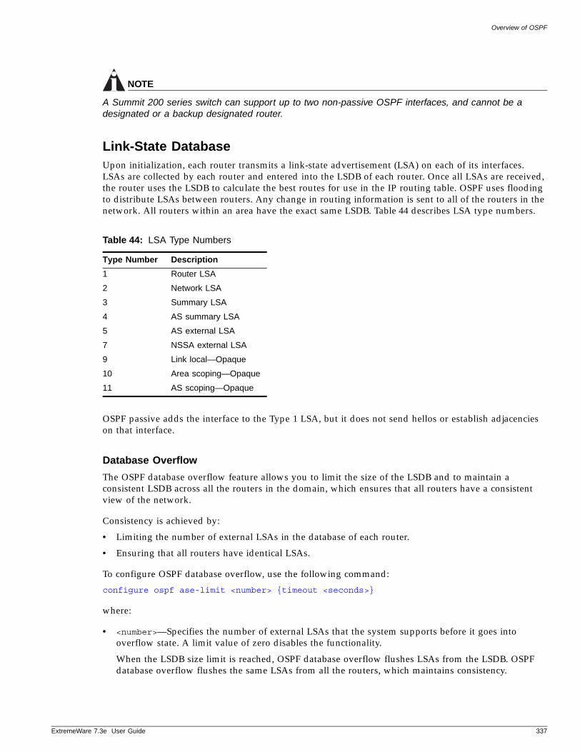
Overview of OSPF
ExtremeWare 7
NOTE
A Summit 200 series switch can support up to two non-passive OSPF interfaces, and cannot be a designated or a backup designated router.
Link-State DatabaseUpon initialization, each router transmits a link-state advertisement (LSA) on each of its interfaces. LSAs are collected by each router and entered into the LSDB of each router. Once all LSAs are received, the router uses the LSDB to calculate the best routes for use in the IP routing table. OSPF uses flooding to distribute LSAs between routers. Any change in routing information is sent to all of the routers in the network. All routers within an area have the exact same LSDB. Table 44 describes LSA type numbers.
OSPF passive adds the interface to the Type 1 LSA, but it does not send hellos or establish adjacencies on that interface.
Database Overflow
The OSPF database overflow feature allows you to limit the size of the LSDB and to maintain a consistent LSDB across all the routers in the domain, which ensures that all routers have a consistent view of the network.
Consistency is achieved by:
• Limiting the number of external LSAs in the database of each router.
• Ensuring that all routers have identical LSAs.
To configure OSPF database overflow, use the following command:
configure ospf ase-limit <number> {timeout <seconds>}
where:
• <number>—Specifies the number of external LSAs that the system supports before it goes into overflow state. A limit value of zero disables the functionality.
When the LSDB size limit is reached, OSPF database overflow flushes LSAs from the LSDB. OSPF database overflow flushes the same LSAs from all the routers, which maintains consistency.
Table 44: LSA Type Numbers
Type Number Description
1 Router LSA
2 Network LSA
3 Summary LSA
4 AS summary LSA
5 AS external LSA
7 NSSA external LSA
9 Link local—Opaque
10 Area scoping—Opaque
11 AS scoping—Opaque
.3e User Guide 337
Interior Gateway Protocols
• timeout—Specifies the timeout, in seconds, after which the system ceases to be in overflow state. A timeout value of zero leaves the system in overflow state until OSPF is disabled and re-enabled.
Opaque LSAs
Opaque LSAs are a generic OSPF mechanism used to carry auxiliary information in the OSPF database. Opaque LSAs are most commonly used to support OSPF traffic engineering.
Normally, support for opaque LSAs is auto-negotiated between OSPF neighbors. In the event that you experience interoperability problems, you can disable opaque LSAs across the entire system using the following command:
disable ospf capability opaque-lsa
To re-enable opaque LSAs across the entire system, use the following command:
enable ospf capability opaque-lsaenable ospf capability opaque-lsa
If your network uses opaque LSAs, we recommend that all routers on your OSPF network support opaque LSAs. Routers that do not support opaque LSAs do not store or flood them. At minimum a well-interconnected subsection of your OSPF network needs to support opaque LSAs to maintain reliability of their transmission.
On an OSPF broadcast network, the designated router (DR) must support opaque LSAs or none of the other routers on that broadcast network will reliably receive them. You can use the OSPF priority feature to give preference to an opaque-capable router, so that it becomes the elected DR.
For transmission to continue reliably across the network, the backup designated router (BDR) must also support opaque LSAs.
AreasOSPF allows parts of a network to be grouped together into areas. The topology within an area is hidden from the rest of the autonomous system. Hiding this information enables a significant reduction in LSA traffic, and reduces the computations needed to maintain the LSDB. Routing within the area is determined only by the topology of the area.
The three types of routers defined by OSPF are as follows:
• Internal Router (IR)—An internal router has all of its interfaces within the same area.
• Area Border Router (ABR)—An ABR has interfaces in multiple areas. It is responsible for exchanging summary advertisements with other ABRs. You can create a maximum of 7 non-zero areas.
• Autonomous System Border Router (ASBR)—An ASBR acts as a gateway between OSPF and other routing protocols, or other autonomous systems.
Backbone Area (Area 0.0.0.0)
Any OSPF network that contains more than one area is required to have an area configured as area 0.0.0.0, also called the backbone. All areas in an autonomous system must be connected to the backbone. When designing networks, you should start with area 0.0.0.0, and then expand into other areas.
338 ExtremeWare 7.3e User Guide
Overview of OSPF
ExtremeWare 7
NOTE
Area 0.0.0.0 exists by default and cannot be deleted or changed.
The backbone allows summary information to be exchanged between ABRs. Every ABR hears the area summaries from all other ABRs. The ABR then forms a picture of the distance to all networks outside of its area by examining the collected advertisements, and adding in the backbone distance to each advertising router.
When a VLAN is configured to run OSPF, you must configure the area for the VLAN. If you want to configure the VLAN to be part of a different OSPF area, use the following command:
configure ospf add vlan <vlan name> area <area identifier>
If this is the first instance of the OSPF area being used, you must create the area first using the following command:
create ospf area <area identifier>
Stub Areas
OSPF allows certain areas to be configured as stub areas. A stub area is connected to only one other area. The area that connects to a stub area can be the backbone area. External route information is not distributed into stub areas. Stub areas are used to reduce memory consumption and computation requirements on OSPF routers. Use the following command to configure an OSPF area as a stub area:
configure ospf area <area identifier> stub [summary | nosummary] stub-default-cost <cost>
Not-So-Stubby-Areas (NSSA)
NSSAs are similar to the existing OSPF stub area configuration option, but have the following two additional capabilities:
• External routes originating from an ASBR connected to the NSSA can be advertised within the NSSA.
• External routes originating from the NSSA can be propagated to other areas, including the backbone area.
The CLI command to control the NSSA function is similar to the command used for configuring a stub area, as follows:
configure ospf area <area identifier> nssa [summary | nosummary] stub-default-cost <cost> {translate}
The translate option determines whether type 7 LSAs are translated into type 5 LSAs. When configuring an OSPF area as an NSSA, the translate should only be used on NSSA border routers, where translation is to be enforced. If translate is not used on any NSSA border router in a NSSA, one of the ABRs for that NSSA is elected to perform translation (as indicated in the NSSA specification). The option should not be used on NSSA internal routers. Doing so inhibits correct operation of the election algorithm.
.3e User Guide 339
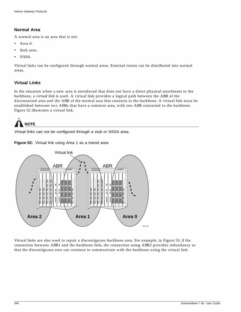
Interior Gateway Protocols
Normal Area
A normal area is an area that is not:
• Area 0.
• Stub area.
• NSSA.
Virtual links can be configured through normal areas. External routes can be distributed into normal areas.
Virtual Links
In the situation when a new area is introduced that does not have a direct physical attachment to the backbone, a virtual link is used. A virtual link provides a logical path between the ABR of the disconnected area and the ABR of the normal area that connects to the backbone. A virtual link must be established between two ABRs that have a common area, with one ABR connected to the backbone. Figure 52 illustrates a virtual link.
NOTE
Virtual links can not be configured through a stub or NSSA area.
Figure 52: Virtual link using Area 1 as a transit area
Virtual links are also used to repair a discontiguous backbone area. For example, in Figure 53, if the connection between ABR1 and the backbone fails, the connection using ABR2 provides redundancy so that the discontiguous area can continue to communicate with the backbone using the virtual link.
ABR ABR
EW_016
Virtual link
Area 2 Area 1 Area 0
340 ExtremeWare 7.3e User Guide
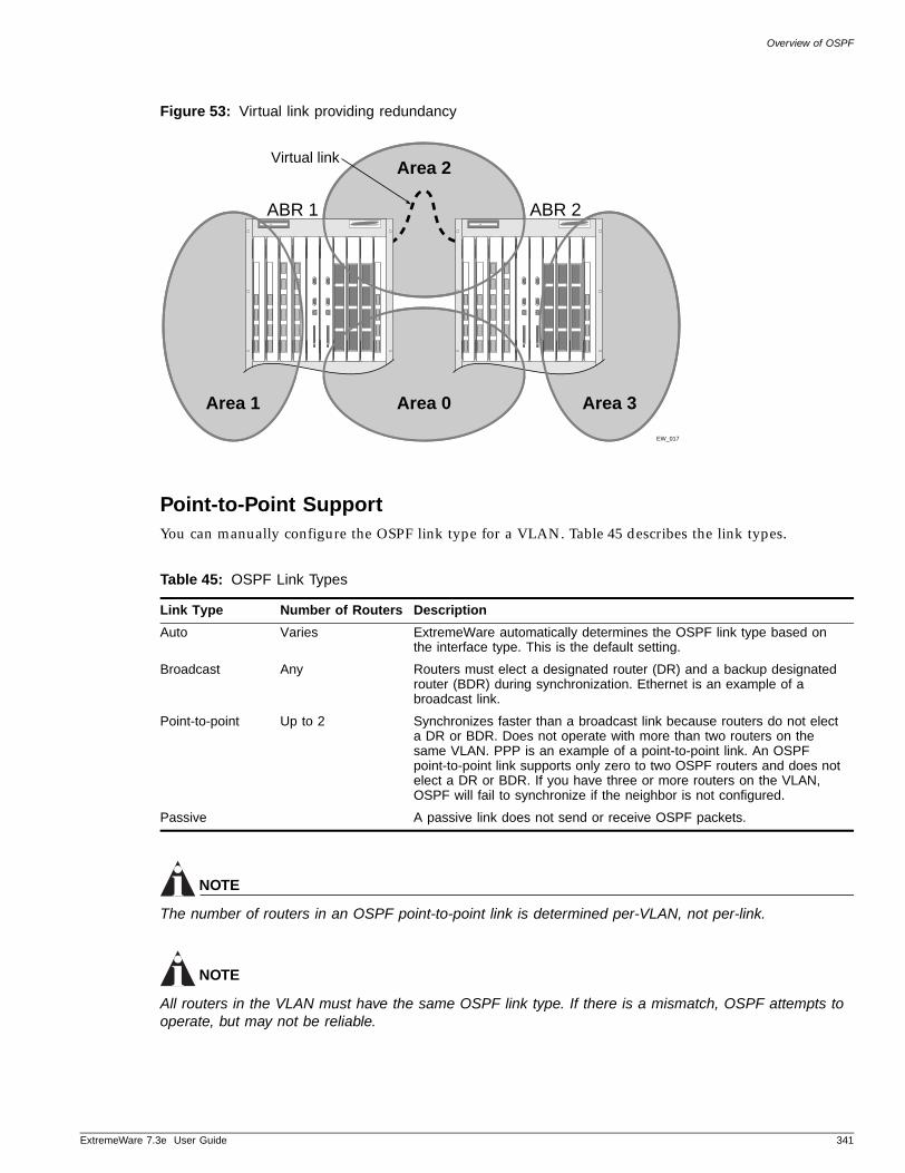
Overview of OSPF
ExtremeWare 7
Figure 53: Virtual link providing redundancy
Point-to-Point SupportYou can manually configure the OSPF link type for a VLAN. Table 45 describes the link types.
NOTE
The number of routers in an OSPF point-to-point link is determined per-VLAN, not per-link.
NOTE
All routers in the VLAN must have the same OSPF link type. If there is a mismatch, OSPF attempts to operate, but may not be reliable.
Table 45: OSPF Link Types
Link Type Number of Routers Description
Auto Varies ExtremeWare automatically determines the OSPF link type based on the interface type. This is the default setting.
Broadcast Any Routers must elect a designated router (DR) and a backup designated router (BDR) during synchronization. Ethernet is an example of a broadcast link.
Point-to-point Up to 2 Synchronizes faster than a broadcast link because routers do not elect a DR or BDR. Does not operate with more than two routers on the same VLAN. PPP is an example of a point-to-point link. An OSPF point-to-point link supports only zero to two OSPF routers and does not elect a DR or BDR. If you have three or more routers on the VLAN, OSPF will fail to synchronize if the neighbor is not configured.
Passive A passive link does not send or receive OSPF packets.
ABR 1 ABR 2
EW_017
Area 2
Area 1 Area 0 Area 3
Virtual link
.3e User Guide 341
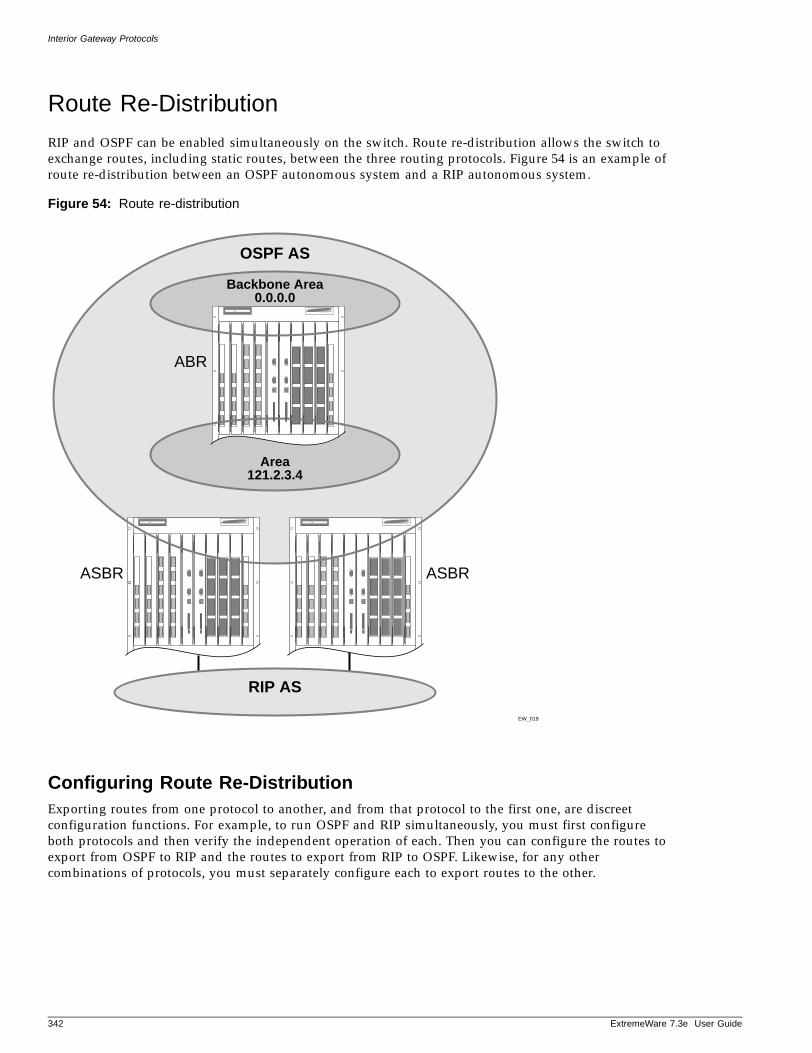
Interior Gateway Protocols
Route Re-Distribution
RIP and OSPF can be enabled simultaneously on the switch. Route re-distribution allows the switch to exchange routes, including static routes, between the three routing protocols. Figure 54 is an example of route re-distribution between an OSPF autonomous system and a RIP autonomous system.
Figure 54: Route re-distribution
Configuring Route Re-DistributionExporting routes from one protocol to another, and from that protocol to the first one, are discreet configuration functions. For example, to run OSPF and RIP simultaneously, you must first configure both protocols and then verify the independent operation of each. Then you can configure the routes to export from OSPF to RIP and the routes to export from RIP to OSPF. Likewise, for any other combinations of protocols, you must separately configure each to export routes to the other.
EW_019
OSPF AS
Backbone Area0.0.0.0
Area121.2.3.4
ABR
ASBR ASBR
RIP AS
342 ExtremeWare 7.3e User Guide
RIP Configuration Example
ExtremeWare 7
Re-Distributing Routes into OSPF
Enable or disable the exporting of RIP, static, and direct (interface) routes to OSPF using the following commands:
enable ospf export [direct | rip | static] [cost <number> [ase-type-1 | ase-type-2] {tag <number>}]
disable ospf export [direct | rip | static]
These commands enable or disable the exporting of RIP, static, and direct routes by way of LSA to other OSPF routers as AS-external type 1 or type 2 routes. The default setting is disabled.
The cost metric is inserted for all RIP, static, and direct routes injected into OSPF. If the cost metric is set to 0, the cost is inserted from the route. The tag value is used only by special routing applications. Use 0 if you do not have specific requirements for using a tag. The tag value in this instance has no relationship with 802.1Q VLAN tagging.
The same cost, type, and tag values can be inserted for all the export routes, or route maps can be used for selective insertion. When a route map is associated with the export command, the route map is applied on every exported route. The exported routes can also be filtered using route maps. Routes filtered with a route map will be exported as ase-type-1.
Enable or disable the export of virtual IP addresses to other OSPF routers using the following commands:
Verify the configuration using the command:
show ospf
You must configure ExtremeWare to export the direct routes to OSPF. You can use an access profile to filter unnecessary direct routes, using the command:
configure ospf direct-filter [<access profile> | none]
Re-Distributing Routes into RIP
Enable or disable the exporting of static, direct, and OSPF-learned routes into the RIP domain using the following commands:
enable rip export [direct | ospf | ospf-extern1 | ospf-extern2 | ospf-inter | ospf-intra | static] cost <number> {tag <number>}
disable rip export [direct | | ospf | ospf-extern1 | ospf-extern2 | ospf-inter | ospf-intra | static]
These commands enable or disable the exporting of static, direct, and OSPF-learned routes into the RIP domain. You can choose which types of OSPF routes are injected, or you can simply choose ospf, which will inject all learned OSPF routes regardless of type. The default setting is disabled.
RIP Configuration Example
A switch that has three VLANs is defined as follows:
• Finance
.3e User Guide 343
Interior Gateway Protocols
— Contain ports 5 and 6.
— IP address 192.207.35.1.
• Personnel
— Contain ports 22 and 23.
— IP address 192.207.36.1.
In this configuration, all IP traffic from stations connected to ports 5 and 6 have access to the switch by way of the VLAN Finance. Ports 22 and 23 reach the switch by way of the VLAN Personnel.
The example is configured as follows:
create vlan Financecreate vlan Personnel
configure Finance protocol ipconfigure Personnel protocol ip
configure Finance add port 5, 6configure Personnel add port 22, 23
configure Finance ipaddress 192.207.35.1configure Personnel ipaddress 192.207.36.1
enable ipforwardingconfigure rip add vlan allenable rip
Configuring OSPF
Each switch that is configured to run OSPF must have a unique router ID. It is recommended that you manually set the router ID of the switches participating in OSPF, instead of having the switch automatically choose its router ID based on the highest interface IP address. Not performing this configuration in larger, dynamic environments could result in an older link state database remaining in use.
Configuring OSPF Wait IntervalExtremeWare allows you to configure the OSPF wait interval, rather than using the router dead interval.
CAUTION
Do not configure OSPF timers unless you are comfortable exceeding OSPF specifications. Non-standard settings might not be reliable under all circumstances.
To specify the timer intervals, use the following command:
configure ospf timer
You can configure the following parameters:
344 ExtremeWare 7.3e User Guide
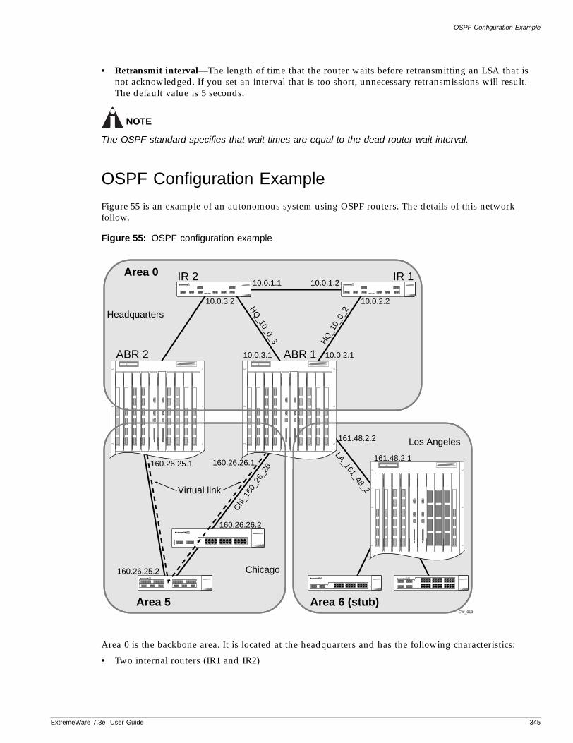
OSPF Configuration Example
ExtremeWare 7
• Retransmit interval—The length of time that the router waits before retransmitting an LSA that is not acknowledged. If you set an interval that is too short, unnecessary retransmissions will result. The default value is 5 seconds.
NOTE
The OSPF standard specifies that wait times are equal to the dead router wait interval.
OSPF Configuration Example
Figure 55 is an example of an autonomous system using OSPF routers. The details of this network follow.
Figure 55: OSPF configuration example
Area 0 is the backbone area. It is located at the headquarters and has the following characteristics:
• Two internal routers (IR1 and IR2)
Area 010.0.1.1
10.0.3.2
10.0.3.1
160.26.25.1
161.48.2.2
161.48.2.1
10.0.2.1
HQ
_10_
0_2
Chi
_160
_26_
26
HQ
_10_0_310.0.2.2
10.0.1.2
Area 6 (stub)
Virtual link
IR 2 IR 1
ABR 1ABR 2
Headquarters
Los Angeles
EW_018
LA_161_48_2
160.26.26.2
Area 5
Chicago160.26.25.2
160.26.26.1
.3e User Guide 345
Interior Gateway Protocols
• Two area border routers (ABR1 and ABR2)
• Network number 10.0.x.x
• Two identified VLANs (HQ_10_0_2 and HQ_10_0_3)
Area 5 is connected to the backbone area by way of ABR1 and ABR2. It is located in Chicago and has the following characteristics:
• Network number 160.26.x.x
• One identified VLAN (Chi_160_26_26)
• Two internal routers
Area 6 is a stub area connected to the backbone by way of ABR1. It is located in Los Angeles and has the following characteristics:
• Network number 161.48.x.x
• One identified VLAN (LA_161_48_2)
• Three internal routers
• Uses default routes for inter-area routing
Two router configurations for the example in Figure 55 are provided in the following section.
Configuration for ABR1The router labeled ABR1 has the following configuration:
create vlan HQ_10_0_2create vlan HQ_10_0_3create vlan LA_161_48_2create vlan Chi_160_26_26
configure vlan HQ_10_0_2 ipaddress 10.0.2.1 255.255.255.0configure vlan HQ_10_0_3 ipaddress 10.0.3.1 255.255.255.0configure vlan LA_161_48_26 ipaddress 161.48.2.26 255.255.255.0configure vlan Chi_160_26_26 ipaddress 160.26.2.1 255.255.255.0
create ospf area 0.0.0.5create ospf area 0.0.0.6
enable ipforwarding
configure ospf area 0.0.0.6 stub nosummary stub-default-cost 10configure ospf add vlan LA_161_48_2 area 0.0.0.6configure ospf add vlan Chi_160_26_26 area 0.0.0.5configure ospf add vlan all area 0.0.0.0
enable ospf
Configuration for IR1The router labeled IR1 has the following configuration:
configure vlan HQ_10_0_1 ipaddress 10.0.1.2 255.255.255.0configure vlan HQ_10_0_2 ipaddress 10.0.2.2 255.255.255.0
346 ExtremeWare 7.3e User Guide
Displaying OSPF Settings
ExtremeWare 7
enable ipforwardingconfigure ospf add vlan all area 0.0.0.0enable ospf
Displaying OSPF Settings
There are a number of commands you can use to display settings for OSPF. To show global OSPF information, use the show ospf command with no options.
To display information about one or all OSPF areas, use the following command:
show ospf area <area identifier>
The detail option displays information about all OSPF areas in a detail format.
To display information about OSPF interfaces for an area, a VLAN, or for all interfaces, use the following command:
show ospf interfaces {vlan <vlan name> | area <area identifier>}
The detail option displays information about all OSPF interfaces in a detail format.
OSPF LSDB DisplayExtremeWare provides several filtering criteria for the show ospf lsdb command. You can specify multiple search criteria and only results matching all of the criteria are displayed. This allows you to control the displayed entries in large routing tables.
To display the current link-state database, use the following command:
show ospf lsdb area [all | <area identifier>[/<len>] | detail | interface | lsid <id>[/<len>] | lstype [all | as-external | external-type7 | network | opaque-area | opaque-global | opaque-local | router | summary-asb |summary-net| routerid <id>[/<len>] | stats | summary | vlan <vlan name>]
The detail option displays all fields of matching LSAs in a multi-line format. The summary option displays several important fields of matching LSAs, one line per LSA. The stats option displays the number of matching LSAs, but not any of their contents. If not specified, the default is to display in the summary format.
A common use of this command is to omit all optional parameters, resulting in the following shortened form:
show ospf lsdb
The shortened form displays all areas and all types in a summary format.
AuthenticationAuthentication is supported at two different levels: interface, and domain or area.
• Interface authentication—prevents unauthorized routers from forming adjacency. This is achieved by inserting authentication information in the Hello PDUs and validating them on the received Hello PDUs. You can configure authentication separately for level 1 and level 2.
.3e User Guide 347
Interior Gateway Protocols
• Domain or area authentication—prevents intruders from injecting invalid routing information into this router. Similar to interface authentication, this is achieved by inserting the authentication information using LSP, CSNP, and PSNP PDUs and validating them on receipt. You can configure authentication separately for level 1 and level 2.
At each of the above levels two different authentication methods are supported: simple password as specified in ISO/IEC 10589, and HMAC-MD5 as specified in draft-ietf-isis-hmac-00.txt.
Summarizing Level 1 IP Routing InformationLevel 2 routers include in their level 2 LSPs a list of all combinations (IP address, subnet mask, and metric) reachable in the level 1 area attached to them. This information is gathered from the level 1 LSPs from all routers in the area. By default the combinations from all the level 1 routers are included in the level 2 LSPs. Summarization of the level 1 combinations reduces the amount of information stored on the level 2 router and helps in scaling to a large routing domain.
You can configure the level 1 areas with one or more combinations for announcement in their level 2 LSPs. The level 1 IP routing information is matched against the summary addresses configured on the level 1 area. Matches are included in the level 2 LSP.
You can also configure the level 2 router to disregard the summary information. This effectively acts as a filter, preventing reachability information from being included in the level 2 LSP.
Filtering Level 1 IP Routing InformationLevel 2 routers include in their level 2 LSPs a list of all combinations (IP address, subnet mask, and metric) reachable in the level 1 area attached to them. This information is gathered from the level 1 LSPs from all routers in the area. By default the combinations from all the level 1 routers are included in the level 2 LSPs. Filtering the level 1 combinations prevents the advertisement of the information to other parts of the domain. This creates a network that is reachable only from routers within the area.
You can configure the level 1 areas in the router with an IP access profile. The level 1 IP routing information in the level 2 LSP is matched against the access profile, and if the result is a deny, the information is not included in the level 2 LSP.
Originating Default RouteThis feature injects IP routing information for the default route in the LSP originated by the router, thereby advertising the router as the default gateway.
Injection of the default route into the level 2 subdomain and level 1 area can be controlled individually. You can configure the metric and metric type associated with the default route. You can also configure the default to be automatically generated based on the presence of a default route in the kernel routing table.
Overload BitThis feature forces the router to set the overload bit (also known as the hippity bit) in its non-pseudo node link-state packets. Normally the setting of the overload bit is allowed only when a router runs into problems. For example, when a router has a memory shortage, it might be that the Link State database is not complete, resulting in an incomplete or inaccurate routing table. By setting the overload bit in its LSPs, other routers can ignore the unreliable router in their SPF calculations until the router has recovered from its problems.
348 ExtremeWare 7.3e User Guide
Displaying OSPF Settings
ExtremeWare 7
Set the overload bit when you want to prevent traffic flow.
Default Routes to Nearest Level 1/2 Switch for Level 1 Only Switches
When one router is a level 1 switch, the route to the nearest level 1/2 switch which attaches to a level 2 backbone network may be installed in the kernel routing table of the level 1 switch.
There are three kinds of level 1 only switches:
• a switch that does not attach to any level 1/2 switch; it is part of a level 1 only network
• a switch that attaches to at least one level 1/2 switch, but none of the level 1/2 switches are attached to a level 2 backbone network. Here the level 1 non-pseudo node LSP of the level 1/2 switches should set the attach bit to 0. A level 1 only switch will not install the default routes based on the unattached level 1/2 switch’s LSP information.
• a switch that attaches to at least one level 1/2 switch, and at least one of the level 1/2 switches is attached to the level 2 backbone network. Here the level 1 non-pseudo node LSP of the level 1/2 switch should set the attach bit to 1. A level 1 only switch will install the default routes based on the attached level 1/2 switch’s LSP information.
The level 1/2 switch that is attached to the level 2 backbone network when at least one of area addresses of level 2 LSP received from other level 2 or level 1/2 switches is not in the list of the level 1 union area address set.
.3e User Guide 349

Interior Gateway Protocols
350 ExtremeWare 7.3e User Guide
19 IP Multicast Routing
ExtremeWare 7
This chapter covers the following topics:
• IP Multicast Routing Overview on page 351
• PIM Sparse Mode (PIM-SM) Overview on page 352
• IGMP Overview on page 354
• Multicast Tools on page 355
• Configuring IP Multicasting Routing on page 356
For more information on IP multicasting, refer to the following publications:
• RFC 1112 – Host Extension for IP Multicasting
• RFC 2236 – Internet Group Management Protocol, Version 2
• PIM-SM Version 2 – draft_ietf_pim_sm_v2_new_04
The following URLs point to the Web sites for the IETF Working Groups:
IEFT PIM Working Group:
http://www.ietf.org/html.charters/pim-charter.html
IP Multicast Routing Overview
IP multicast routing is a function that allows a single IP host to send a packet to a group of IP hosts. This group of hosts can include devices that reside on the local network, within a private network, or outside of the local network.
IP multicast routing consists of the following functions:
• A router that can forward IP multicast packets.
• A router-to-router multicast routing protocol (such as Protocol Independent Multicast- Sparse Mode (PIM-SM).
• A method for the IP host to communicate its multicast group membership to a router (for example, Internet Group Management Protocol (IGMP)).
.3e User Guide 351
IP Multicast Routing
NOTE
You should configure IP unicast routing before you configure IP multicast routing.
PIM Sparse Mode (PIM-SM) Overview
Protocol independent Multicast-Sparse Mode (PIM-SM) routes multicast packets to multicast groups. The sparse mode protocol is designed for installations where the multicast groups are scattered over a large area such as a wide area network (WAN). PIM-SM is a router-to-router protocol, so all routers and switches must upgrade to the same PIM-SM version. Summit series “e”switches use PIM-SM version 2 to forward IP packets that are destined to the IP addresses in the Class D Range to multiple networks using the Multicast Routing information setup.
PIM-SM is an explicit join and prune protocol that is a mixture of the shared tree and shortest path tree (SPT) models. The routers must explicitly join the group(s) in which they are interested in becoming a member, which is beneficial for large networks that have group members who are sparsely distributed. PIM-SM is not dependant on a specific unicast routing protocol. Summit series “e”switches support IGMPV2, which allows network hosts to report the multicast group membership to the switch.
Using PIM-SM, the source router sends a join message to a known rendezvous point (RP). The RP is a central multicast router that is responsible for receiving and distributing multicast packets. RPs are elected by a bootstrap router (BSR). The job of the BSR is to broadcast bootstrap messages, which has a collection of RP advertisements. You may only configure the “e” series switches in static mode, to point to a non-Summit switch. In PIM edge mode, the RP address cannot be the local interface IP address. In this mode, the local router cannot act as an RP or BSR. Summit series “e”switches are not eligible to be BSRs or RPs.
When a source router has a multicast packet to distribute, it encapsulates the packet in a unicast message and sends it to the RP. The RP decapsulates the multicast packet and distributes it among all member routers.
When a last-hop, receiving router determines that the multicast rate has exceeded a configured threshold, that router can send an explicit join to the originating router. Once this occurs, the receiving router gets the multicast directly from the sending router, and bypasses the RP.
Configuring PIM-SM
You can configure two active and 254 passive interfaces on Summit series “e”switches for PIM-SM. By default the interface is configured as active. To enable the interface as passive, specify the passive keyword. The following command enables PIM-SM on an IP interface.
configure pim add {vlan} [<vlan name>] {passive}
The following command disables PIM-SM on an IP interface:
configure pim delete vlan [<vlan name> | all]
For example, to add a VLAN named lobby, as an active interface, you would enter:
configure pim add vlan lobby
352 ExtremeWare 7.3e User Guide
PIM Sparse Mode (PIM-SM) Overview
ExtremeWare 7
In PIM edge mode, the RP address cannot be the local interface IP address. For example, in edge mode, the local router cannot act as an RP or a BSR. Use the core mode of PIM, to configure a local router as an RP or a BSR.
To configure an RP and its associated groups statically, enter the following command:
configure pim crp static <rp address> [none | <access profile>] {<priority [0-254]>}
The access profile contains a list of multicast group accesses served by the RP.
For example, the following command statically configures an RP and its associated groups defined in access profile rp-list:
configure pim crp static 10.0.3.1 rp-list
To configure the PIM hello and join/prune interval for PIM-SM timers, enter this command:
configure pim timer <hello interval> <join prune interval> vlan [<vlan name>]
Specify the intervals in seconds. The hello interval specifies the amount of time before a hello message is sent out by the PIM router. The join prune interval is the amount of time before a join or a prune command is executed. The valid range for both intervals is 1 to 65,519 seconds. The default for the hello interval is 30 seconds; the default for join prune is 60 seconds.
Because PIM leverages the unicast routing capability that is already present in the switch, the access policy capabilities are, by nature, different. When the PIM protocol is used for routing IP multicast traffic, the switch can be configured to use an access profile to determine trusted PIM router neighbors for the VLAN on the switch running PIM. To configure a trusted neighbor policy enter the following command:
configure pim vlan [<vlan name> | all] trusted-gateway [<access profile> | none]
For example, the following command configures a trusted neighbor policy on the VLAN backbone:
configure pim vlan backbone trusted-gateway <access profile>
To configure the threshold (in Kbps) for switching to SPT, enter the following command:
configure pim spt-threshold <last hop router threshold> {<rp threshold>}
On leaf routers, this setting is based on data packets. On the RP, this setting is based on register packet rate in Kbps.
The following command configures the checksum computation to either include data (for compatibility with Cisco Systems products) or to exclude data (for RFC-compliant operation), in the register message:
configure pim register-checksum-to [include-data | exclude-data]
Enabling and Disabling PIM-SM
To enable or disable PIM-SM on the system, enter the following command:
enable pim
or
disable pim
.3e User Guide 353
IP Multicast Routing
To display the PIM configuration and statistics, enter the following command:
show pim {detail | rp-set {<IP multicast group>}| vlan <vlan name>}
IGMP Overview
To constrain the flooding of multicast traffic, configure switch interfaces to use Internet Group Management Protocol (IGMP) snooping so that multicast traffic is forwarded only to interfaces associated with IP multicast entities. IGMP is a protocol used by an IP host to register its IP multicast group membership with a router. Periodically, the router queries the multicast group to see if the group is still in use. If the group is still active, a single IP host responds to the query, and group registration is maintained.
IGMP is enabled by default on the switch. However, the switch can be configured to disable the generation of periodic IGMP query packets. IGMP should be enabled when the switch is configured to perform IP unicast or IP multicast routing.
IGMP SnoopingIGMP snooping is a layer 2 function of the switch. It does not require multicast routing to be enabled. In IGMP snooping, the layer 2 switch keeps track of IGMP requests, and only forwards multicast traffic to the part of the local network that requires it. IGMP snooping optimizes the usage of network bandwidth, and prevents multicast traffic from being flooded to parts of the local network that do not need it. The switch does not reduce any IP multicast traffic in the local multicast domain (224.0.0.x).
IGMP snooping is enabled by default on the switch. If IGMP snooping is disabled, all IGMP and IP multicast traffic floods within a given VLAN. IGMP snooping expects at least one device on every VLAN to periodically generate IGMP query messages. The static IGMP snooping entries do not require periodic query. An optional optimization for IGMP snooping is the strict recognition of multicast routers only if the remote devices have joined the PIM (244.0.0.13) multicast groups.
When a port sends an IGMP leave message, the switch removes the IGMP snooping entry after 1000 milli-seconds (the leave time is configurable, ranging from 0 to 10000 ms). The switch sends a query to determine which ports want to remain in the multicast group. If other members of the VLAN want to remain in the multicast group, the router ignores the leave message, but the port that requests removal is removed from the IGMP snooping table.
If the last port within a VLAN sends an IGMP leave message, then the router will not receive any responses to the query, and the router will remove the VLAN from the multicast group in 3 seconds.
Static IGMPIn order to receive multicast traffic, a host needs to explicitly join a multicast group by sending an IGMP request, then the traffic is forwarded to that host. There are situations where you would like multicast traffic to be forwarded to a port where a multicast enabled host is not available (for example, testing multicast configurations). Static IGMP emulates a host or router attached to a switch port, so that multicast traffic will be forwarded to that port. Emulate a host to forward a particular multicast group to a port; emulate a router to forward all multicast groups to a port. Use the following command to emulate a host on a port:
configure igmp snooping vlan <vlan name> ports <portlist> add static group <ip address>
354 ExtremeWare 7.3e User Guide
Multicast Tools
ExtremeWare 7
Use the following command to emulate a multicast router on a port:
configure igmp snooping vlan <vlan name> ports <portlist> add static router
To remove these entries, use the corresponding command:
configure igmp snooping vlan <vlan name> ports <portlist> delete static group [<ip address> | all] configure igmp snooping vlan <vlan name> ports <portlist> delete static router
To display the IGMP snooping static groups, use the following command:
show igmp snooping {vlan <vlan name>} static group
IGMP Snooping Filters
IGMP snooping filters allow you to configure an access profile on a port to allow or deny IGMP report and leave packets coming into the port. For details on creating access profiles, see the section, “Routing Access Profiles” on page 160. For the access profiles used as IGMP snooping filters, all the profile entries should IP address type entries, and the IP address of each entry must be in the class-D multicast address space, but should not be in the multicast control packet range (224.0.0.x/24). After you have created an access profile, use the following command to associate the access profile and filter with a set of ports:
configure igmp snooping vlan <vlan name> ports <portlist> filter [<access profile> | none]
To remove the filter, use the none option as shown in the following example:
configure igmp snooping vlan <vlan name> ports <portlist> filter none
To display the IGMP snooping filters, use the following command:
show igmp snooping {vlan <vlan name>} filter
Multicast Tools
ExtremeWare provides two commonly available tools to monitor and troubleshoot IP multicast, mrinfo and mtrace.
MrinfoThe multicast router information tool, (mrinfo), requests information from a router that could be used for tracing and troubleshooting. A request is sent to a multicast router, and the router responds with the following information:
• code version
• system multicast information
• interface information
— interface IP address
— interface multicast capabilities
— metric configured on the interface
.3e User Guide 355
IP Multicast Routing
— threshold configured on the interface
— count and IP address of the neighbors discovered on the interface
Use the following command to send an mrinfo request:
mrinfo <ip address> {from <ip address>} {timeout <seconds>}
Mtrace
Multicast trace (mtrace) relies on a feature of multicast routers that is accessed using the IGMP protocol. Since multicast uses reverse path forwarding, a multicast trace is run from the destination to the source. A query packet is sent to the last-hop multicast router. This router builds a trace response packet, fills in a report for its hop, and forwards the packet to the next upstream router. As the request is forwarded, each router in turn adds its own report to the trace response. When the request reaches the first-hop router, the filled in request is sent back to the system requesting the trace. The request will also be returned if the maximum hop limit is reached.
If a router does not support the mtrace functionality, it will silently drop the request packet and no information will be returned. For this situation, you could send the trace with a small number of maximum hops allowed, increasing the number of hops as the stream is traced.
The group IP address must be in the class-D multicast address space, but should not be in the multicast control subnet range (224.0.0.x/24).
Use the following command to trace a multicast stream:
mtrace source <ip address> {destination <ip address>} {group <ip address>} {from <ip address>} {gateway <ip address >} {timeout <seconds>} {maximum-hops <number>}
Configuring IP Multicasting Routing
To configure IP multicast routing, you must do the following:
1 Configure the system for IP unicast routing.
2 Enable multicast routing on the interface using the following command:
enable ipmcforwarding {vlan <vlan name>}
3 Enable PIM on all IP multicast routing interfaces using the following command:
configure pim add {vlan} [<vlan name>] {passive}
If the vlan option is not supplied, IP multicast cache (ipmc) routing is enabled or disabled on all VLANs. Due to hardware limitations, a port can only be placed into a single VLAN that has IP multicast routing enabled.
4 Enable PIM on the router using one of the following commands:
enable pim
Example—Configuration for IR1The router labeled IR1 has the following configuration:
configure vlan HQ_10_0_1 ipaddress 10.0.1.2 255.255.255.0
356 ExtremeWare 7.3e User Guide
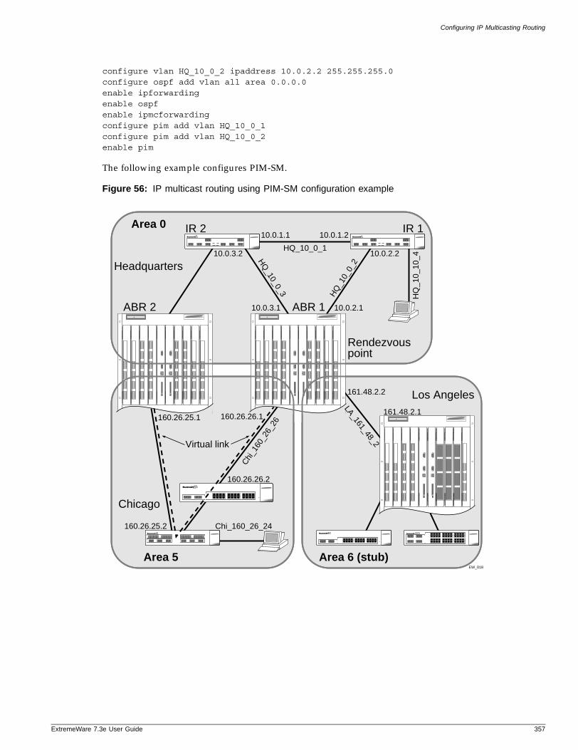
Configuring IP Multicasting Routing
ExtremeWare 7
configure vlan HQ_10_0_2 ipaddress 10.0.2.2 255.255.255.0configure ospf add vlan all area 0.0.0.0enable ipforwardingenable ospfenable ipmcforwardingconfigure pim add vlan HQ_10_0_1configure pim add vlan HQ_10_0_2enable pim
The following example configures PIM-SM.
Figure 56: IP multicast routing using PIM-SM configuration example
Area 010.0.1.1
HQ_10_0_110.0.3.2
10.0.3.1
160.26.25.1
161.48.2.2
161.48.2.1
10.0.2.1
HQ
_10_
0_2
Chi
_160
_26_
26
HQ
_10_0_3
10.0.2.2
10.0.1.2
Area 6 (stub)
Virtual link
IR 2 IR 1
ABR 1
Rendezvouspoint
ABR 2
Headquarters
Los Angeles
EW_018
LA_161_48_2
160.26.26.2
Area 5
Chicago
160.26.25.2 Chi_160_26_24
160.26.26.1H
Q_1
0_10
_4
.3e User Guide 357

IP Multicast Routing
358 ExtremeWare 7.3e User Guide

Part 3
Managing Wireless Networks

20 Wireless Networking
ExtremeWare 7
This chapter describes wireless networking using an Summit 3800 family switch and the Altitude 300 and includes information on the following topics:
• Overview of Wireless Networking on page 361
• Wireless Devices on page 362
• Bridging on page 363
• Managing the Altitude 300 on page 364
• Configuring RF Properties on page 365
• Configuring RF Monitoring on page 368
• Performing Client Scanning on page 372
• Collecting Client History Statistics on page 374
• Configuring Wireless Switch Properties on page 377
• Configuring Wireless Ports on page 378
• Configuring Wireless Interfaces on page 380
• Configuring Inter-Access Point Protocol (IAPP) on page 381
• Event Logging and Reporting on page 382
• Enabling SVP to Support Voice Over IP on page 382
Overview of Wireless Networking
The Summit 300 switch and the Altitude 300 extend network service to wireless 802.11a/b/g clients within a fully integrated network infrastructure. Ports on the Summit 300 switch handle all of the management functions typically associated with an access point. The Altitude 300 serves as the radio transmitter and receiver, inheriting configuration information as soon as it is attached to the switch and as changes are made to the wireless profiles after the system is deployed.
Figure 57 shows a sample network configuration. The Summit 300 switch provides switching service across the wired and wireless network. Each port on the switch is configured with a “personality” that identifies its function.
.3e User Guide 361
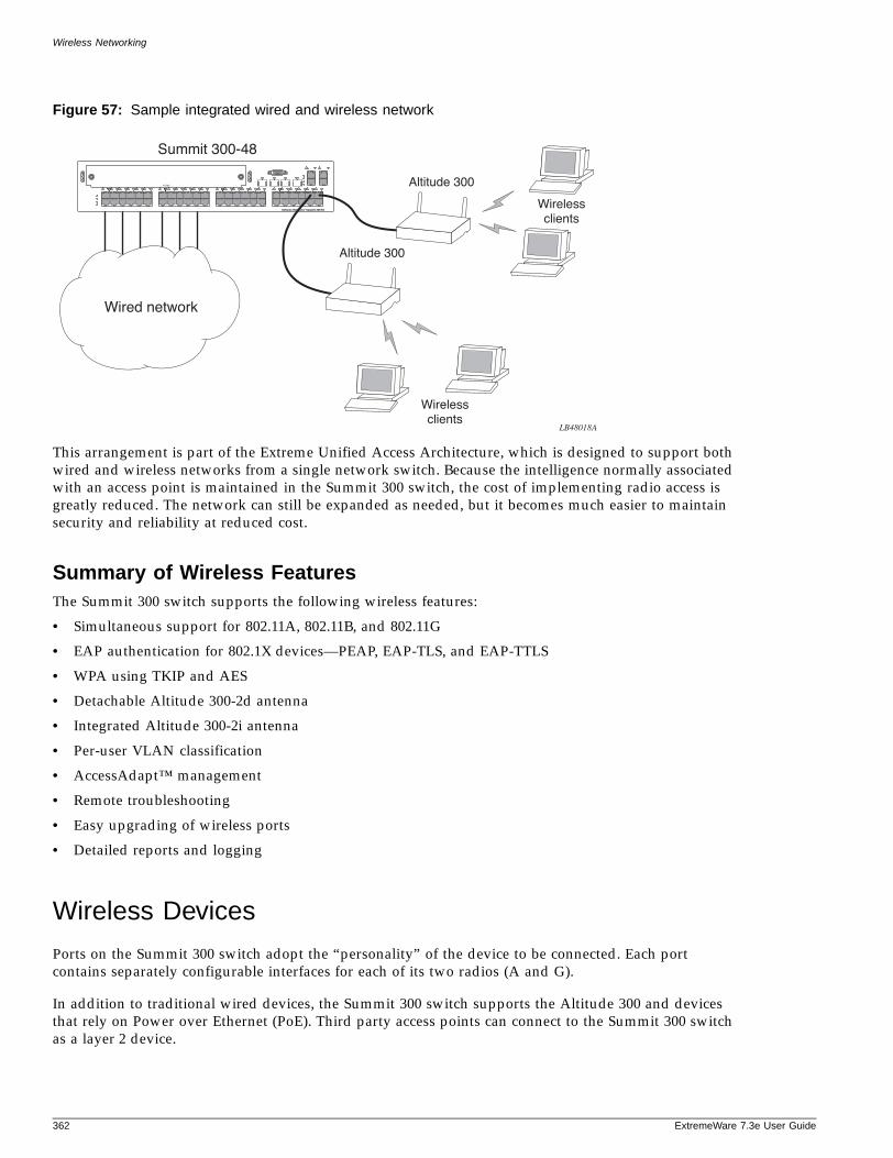
Wireless Networking
Figure 57: Sample integrated wired and wireless network
This arrangement is part of the Extreme Unified Access Architecture, which is designed to support both wired and wireless networks from a single network switch. Because the intelligence normally associated with an access point is maintained in the Summit 300 switch, the cost of implementing radio access is greatly reduced. The network can still be expanded as needed, but it becomes much easier to maintain security and reliability at reduced cost.
Summary of Wireless FeaturesThe Summit 300 switch supports the following wireless features:
• Simultaneous support for 802.11A, 802.11B, and 802.11G
• EAP authentication for 802.1X devices—PEAP, EAP-TLS, and EAP-TTLS
• WPA using TKIP and AES
• Detachable Altitude 300-2d antenna
• Integrated Altitude 300-2i antenna
• Per-user VLAN classification
• AccessAdapt™ management
• Remote troubleshooting
• Easy upgrading of wireless ports
• Detailed reports and logging
Wireless Devices
Ports on the Summit 300 switch adopt the “personality” of the device to be connected. Each port contains separately configurable interfaces for each of its two radios (A and G).
In addition to traditional wired devices, the Summit 300 switch supports the Altitude 300 and devices that rely on Power over Ethernet (PoE). Third party access points can connect to the Summit 300 switch as a layer 2 device.
LB48018A
Wired network
Summit 300-48
Altitude 300
Wirelessclients
Wirelessclients
Altitude 300
362 ExtremeWare 7.3e User Guide
Bridging
ExtremeWare 7
Physical security for the wireless networks ceases to be a problem at the wireless access location, because the Altitude 300 does not store any configuration settings. Information is loaded as needed from the switch. Even if the Altitude 300 is physically moved, it can only be reconnected to another Summit switch.
You can set network policies at layers 2 and 3 to cover both the wired and wireless networks. In this way you can block access to individuals suspected of intrusion across the entire network infrastructure.
Altitude AntennasThe switch automatically detects whether the Altitude 300 has an integrated or detachable antenna. Both the Altitude 300-2i integrated antenna and the detachable Altitude 300-2d antenna are compatible with the Product Name switch.
To setup the switch to correctly use an antenna you need to set the country code. If you are using the Altitude 300-2d detachable antenna, you need to also configure the antenna for indoor or outdoor use to comply with regulatory requirements.
To configure the antenna type as indoor or outdoor, to comply with regulatory requirements, use the following command:
configure wireless ports [<portlist> | all] antenna-location <indoor | outdoor>
NOTE
You cannot configure an integrated antenna for outdoor use.
To set the country code for the antenna, configure the country code on the switch using the following command:
configure wireless country-code <code>
You can then connect the antenna to the Altitude 300. The switch recognizes the correct regulatory-domain for the antenna and allows the antenna to start operating. For more information on configuring county codes, see “Configuring Country Codes” on page 909.
Bridging
Wireless bridging on an Summit 300 switch allows wireless users within the same VLAN to communicate with other wireless users on the same Summit 300 switch using layer 2 bridging. Wireless bridging can be enabled or disabled for each interface of a wireless port, and the setting is locally significant on each Altitude 300. This setting does not prevent bridging between wired and wireless MAC addresses in the same VLAN or between remote wireless stations associated with a remote Altitude 300. To configure wireless bridging, use the following command:
configure wireless ports <portlist> interface [1 | 2] wireless-bridging [on | off]
.3e User Guide 363
Wireless Networking
Managing the Altitude 300
It is not necessary to configure the individual Altitude 300 ports. You set port attributes on the Summit 300 switch, copying them as needed to new ports that you configure. Each time you make a change to wireless configuration on the switch, that change is implemented in the wireless network. Upgrading wireless software becomes extremely easy, since it is only necessary to upgrade the switch, and not the Altitude 300s.
Device management is flexible. From the management system you can enable and disable individual wireless ports or sets of ports based on time, user, or location. You manage the wireless ports from the wired IP network.
Profiles are available for security and RF parameters. Profiles function as templates, eliminating the need to issue repetitive commands and thereby simplifying the process of updating configuration information over multiple ports. You assign profiles to each interface (A or G) on a port and share the profiles across ports. Unless otherwise specified, a default profile is automatically assigned to each new wireless port.
Follow this process to configure wireless ports on the Summit switch:
1 Designate a VLAN as the wireless management VLAN, or use the default management VLAN.Create RF-profiles.
2 Create security profiles and configure security parameters for each. The security profile includes ess-name.
3 Configure wireless ports on the switch by assigning RF profiles and security profiles.
4 Configure a specific channel (determined from a site survey), if desired, on each interface. If you do not configure a specific channel, the switch auto-selects the channel with the least interference.
5 Connect the Altitude 300.
After this process is complete, clients can access your network through the Altitude 300.
Wireless Show Commands
The show commands described in this section can be used to display information on wireless port configuration, RF profiles, security profiles, and stations.
Use the following command to list the data rates and channel for a selected port and interface:
show wireless ports [<portlist> | all] interface [1 | 2] rf-status {detail}
Each wireless port on the switch contains two interfaces. Interface 1 supports 802.11a, and interface 2 supports 802.11b/g radio signals. The show wireless ports interface rf-status command allows you to display information about one of the two individual interfaces (1|2) on a port or ports.
Use the following command to list dot1x and network authorization modes for a selected port and interface:
show wireless ports [<portlist> | all] interface [1 |2] stats
This command displays Wired Equivalent Privacy (WEP) protocol, authentication, dot1x, and ESS name information for the selected port and interface.
Use the following command to check the basic wireless configuration on a switch:
364 ExtremeWare 7.3e User Guide
Configuring RF Properties
ExtremeWare 7
show wireless configuration
This command displays the country, management VLAN, and gateway.
Use the following command to summarize wireless configuration for a selected port and interface:
show wireless ports [<portlist> | all] interface [1 | 2] configuration {detail}
You can use this command to show in table or list format the configuration and state of the interface of the selected port or ports.
Use the following command to list 802.11 interface statistics for a selected port and interface:
show wireless ports [<portlist> | all] interface [1 |2] stats
You can use this command to search for errors on a per interface basis.
Use the following command to display the current state of a selected port and interface:
show wireless ports [<portlist> | all] interface [1 |2] status
You can use this command to examine RF profiles on a per wireless port basis, and view the log of a specific port or ports, filtering out the switch log.
Configuring RF Properties
RF profiles allow you to group RF parameters for access using a single CLI command. The following rules apply for RF profiles:
• After you have defined a profile, subsequent changes automatically apply to all ports assigned to that profile.
• Each RF profile applies to a specific interface (A, B, or G), so changing a profile only affects the specified interface.
• Each Summit switch ships with default profiles for each supported wireless port.
Creating an RF ProfileYou can use the commands described in this section to create RF profiles.
To create a new RF profile by creating a name and associating it with an interface mode, use the following command:
create rf-profile <profile_name> mode [ A | B | B_G | G ]
Use this command to create a new RF profile without copying an existing RF profile.
To create a new RF profile by copying an existing RF profile and assigning a new name, use the following command:
create rf-profile <profile_name> copy <name>
Use this command to create a new profile identified by the string name. The copy argument specifies the name of an existing profile from which to obtain the initial values.
.3e User Guide 365
Wireless Networking
Deleting an RF ProfileYou can use the command described in this section to delete RF profiles.
To delete an RF profile, use the following command:
delete rf-profile <name>
The named profile cannot be attached to any active ports before deletion.
Configuring an RF ProfileYou can use the configuration commands described in this section to set RF profile properties to specific values. Changes take effect immediately and are propagated to all ports that share a particular profile. All failures are written to the syslog.
NOTE
ess-name is no longer part of RF-Profile property values. It is now part of Security Profile property values.
Setting the Beacon Frequency Interval
A beacon is a packet that is broadcast by the Altitude 300 wireless port to synchronize the wireless network. The beacon-interval is the time in milliseconds between beacons.
To specify the frequency interval of a beacon in milliseconds for an RF profile, use the following command:
configure rf-profile <name> beacon-interval <value>
Setting the DTIM Interval
A delivery traffic indication map (DTIM) field is a countdown field informing clients of the next listening window to broadcast and multicast messages. The DTIM count is an integer value that counts down to zero. This value represents the number of beacon frames before the delivery of multicast frames. The DTIM period is the number of beacon frames between multicast frame deliveries. When the wireless port has buffered broadcast or multicast messages, it sends the next DTIM with a DTIM interval value. Its clients hear the beacons and awaken to receive the broadcast and multicast messages.
To specify the interval of the DTIM in number of beacons, use the following command:
configure rf-profile <name> dtim-interval <value>
Clients achieve greater power savings with larger DTM intervals. However, a larger DTM interval will increase the delay before multicast frames are delivered to all stations.
Setting the Fragment Size
The RF profile fragment size property specifies the maximum size for a packet before data is fragmented into multiple packets. To specify the fragment size in bytes, use the following command:
configure rf-profile <name> frag-length <value>
366 ExtremeWare 7.3e User Guide
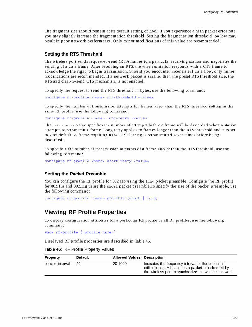
Configuring RF Properties
ExtremeWare 7
The fragment size should remain at its default setting of 2345. If you experience a high packet error rate, you may slightly increase the fragmentation threshold. Setting the fragmentation threshold too low may result in poor network performance. Only minor modifications of this value are recommended.
Setting the RTS Threshold
The wireless port sends request-to-send (RTS) frames to a particular receiving station and negotiates the sending of a data frame. After receiving an RTS, the wireless station responds with a CTS frame to acknowledge the right to begin transmission. Should you encounter inconsistent data flow, only minor modifications are recommended. If a network packet is smaller than the preset RTS threshold size, the RTS and clear-to-send CTS mechanism is not enabled.
To specify the request to send the RTS threshold in bytes, use the following command:
configure rf-profile <name> rts-threshold <value>
To specify the number of transmission attempts for frames larger than the RTS threshold setting in the same RF profile, use the following command:
configure rf-profile <name> long-retry <value>
The long-retry value specifies the number of attempts before a frame will be discarded when a station attempts to retransmit a frame. Long retry applies to frames longer than the RTS threshold and it is set to 7 by default. A frame requiring RTS/CTS clearing is retransmitted seven times before being discarded.
To specify a the number of transmission attempts of a frame smaller than the RTS threshold, use the following command:
configure rf-profile <name> short-retry <value>
Setting the Packet Preamble
You can configure the RF profile for 802.11b using the long packet preamble. Configure the RF profile for 802.11a and 802.11g using the short packet preamble.To specify the size of the packet preamble, use the following command:
configure rf-profile <name> preamble [short | long]
Viewing RF Profile PropertiesTo display configuration attributes for a particular RF profile or all RF profiles, use the following command:
show rf-profile {<profile_name>}
Displayed RF profile properties are described in Table 46.
Table 46: RF Profile Property Values
Property Default Allowed Values Description
beacon-interval 40 20-1000 Indicates the frequency interval of the beacon in milliseconds. A beacon is a packet broadcasted by the wireless port to synchronize the wireless network.
.3e User Guide 367
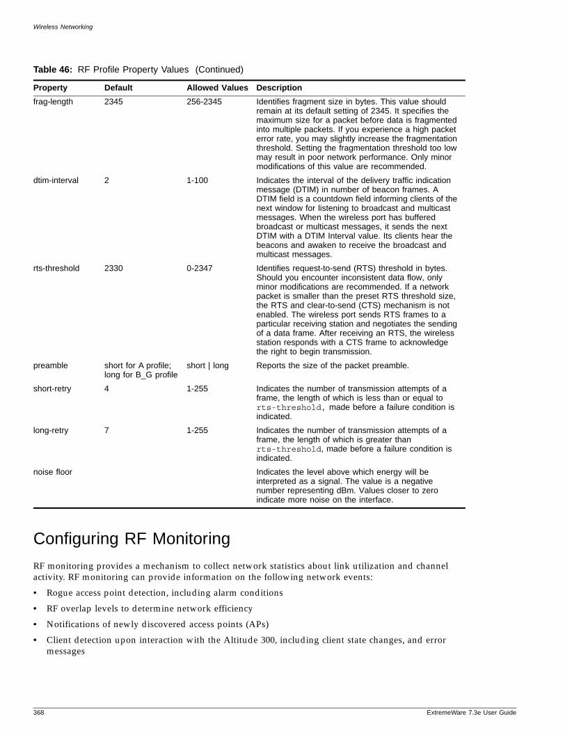
Wireless Networking
Configuring RF Monitoring
RF monitoring provides a mechanism to collect network statistics about link utilization and channel activity. RF monitoring can provide information on the following network events:
• Rogue access point detection, including alarm conditions
• RF overlap levels to determine network efficiency
• Notifications of newly discovered access points (APs)
• Client detection upon interaction with the Altitude 300, including client state changes, and error messages
frag-length 2345 256-2345 Identifies fragment size in bytes. This value should remain at its default setting of 2345. It specifies the maximum size for a packet before data is fragmented into multiple packets. If you experience a high packet error rate, you may slightly increase the fragmentation threshold. Setting the fragmentation threshold too low may result in poor network performance. Only minor modifications of this value are recommended.
dtim-interval 2 1-100 Indicates the interval of the delivery traffic indication message (DTIM) in number of beacon frames. A DTIM field is a countdown field informing clients of the next window for listening to broadcast and multicast messages. When the wireless port has buffered broadcast or multicast messages, it sends the next DTIM with a DTIM Interval value. Its clients hear the beacons and awaken to receive the broadcast and multicast messages.
rts-threshold 2330 0-2347 Identifies request-to-send (RTS) threshold in bytes. Should you encounter inconsistent data flow, only minor modifications are recommended. If a network packet is smaller than the preset RTS threshold size, the RTS and clear-to-send (CTS) mechanism is not enabled. The wireless port sends RTS frames to a particular receiving station and negotiates the sending of a data frame. After receiving an RTS, the wireless station responds with a CTS frame to acknowledge the right to begin transmission.
preamble short for A profile; long for B_G profile
short | long Reports the size of the packet preamble.
short-retry 4 1-255 Indicates the number of transmission attempts of a frame, the length of which is less than or equal to rts-threshold, made before a failure condition is indicated.
long-retry 7 1-255 Indicates the number of transmission attempts of a frame, the length of which is greater than rts-threshold, made before a failure condition is indicated.
noise floor Indicates the level above which energy will be interpreted as a signal. The value is a negative number representing dBm. Values closer to zero indicate more noise on the interface.
Table 46: RF Profile Property Values (Continued)
Property Default Allowed Values Description
368 ExtremeWare 7.3e User Guide
Configuring RF Monitoring
ExtremeWare 7
AP DetectionAccess point (AP) detection can be configured to use either of two methods: passive scan or active scan. During a passive scan, the Altitude 300 simply listens for beacons and other broadcast traffic and uses the collected information to create a database of stations it recognizes. In active scan mode, the Altitude 300 sends a probe request to elicit responses from other APs within its area.
The Altitude 300 support both active and passive scans on the current operating channel. During scans operating on the current channel, the Altitude 300 continues to carry user traffic. During an “off-channel” scan, the Altitude 300 is not be available for user traffic. The effect of an off-channel scan is to disable the radio for a user-defined period of time, during which the Altitude 300 will scan other channels. All associated clients will lose connections and need to reassociate. Once the scan is complete, the radio will be returned to its previous state. You can set the scan to occur on all channels, or on a specific subset of channels at specified scheduled times.
Enabling and Disabling AP Scan
The commands described in this section are used to enable and disable access point (AP) detection.
To start a wireless port on-channel scan for the indicated port or ports and interface for the Altitude 300, use the following command:
enable wireless ports <portlist> interface [1 |2] ap-scan
The Altitude 300 continues to carry user traffic during scans operating on the current channel (“on-channel” scans).
To stop an on-channel wireless port scan for the indicated port or ports and interface for the Altitude 300, use the following command:
disable wireless ports <portlist> interface [1 |2] ap-scan
To start the access point (AP) scan on the indicated interface at the specified time, use the following command:
enable wireless ports <portlist> interface [1 | 2] ap-scan off-channel [at | every] <time>
During an “off-channel” scan, the Altitude 300 is not available for user traffic.
To schedule the stopping of the access point (AP) scan on the indicated interface at the specified time, use the following command:
disable wireless ports <portlist> interface [1 | 2] ap-scan off-channel [at | every] <time>
Configuring AP Scan
The commands described in this section are used to configure access point (AP) detection.
To add or remove specific channels for the off-channel AP scan, use the following command:
configure wireless ports [<portlist> | all] interface [1 | 2] ap-scan off-channel [add | del] {current-channel | all-channels | every-channel}
Use this command when the AP scan must be started on a particular interface.
To enable the sending of probes for active scanning, use the following command:
.3e User Guide 369
Wireless Networking
configure wireless ports [<portlist> | all] interface [1 | 2] ap-scan send-probe <on |off>
To configure the interval between probe request packets for active off-channel scanning, use the following command:
configure wireless ports [<portlist> | all] interface [1 | 2] ap-scan probe-interval <msec>
Use this command to send probe requests at particular intervals on a selected channel during an AP scan.
To set the maximum time an off-channel scan waits at a particular channel, use the following command:
configure wireless ports [<portlist> | all] interface [1 | 2] ap-scan off-channel max-wait <num>
To set the minimum time an off-channel scan waits at a particular channel, use the following command:
configure wireless ports [<portlist> | all] interface [1 | 2] ap-scan off-channel min-wait <num>
To have the AP scan to send an SNMP trap when new stations are added to the results table, use the following command:
configure wireless ports [<portlist> | all] interface [1 | 2] ap-scan added-trap [on | off]
Use this command when an SNMP-based remote management application is used to monitor the network.
To have the AP scan to send an SNMP trap when new stations are removed from the results table, use the following command:
configure wireless ports [<portlist> | all] interface [1 | 2] ap-scan removed-trap [on | off]
Use this command to see a trap when stations are removed from the results table.
To configure the AP scan to send an SNMP trap when information about an AP has changed, use the following command:
configure wireless ports [<portlist> | all] interface [1 | 2] ap-scan updated-trap <on |off>
To set the number of elements that the wireless interface stores, use the following command:
configure wireless ports [<portlist> | all] interface [1 | 2] ap-scan results size <num>
Use this command to specify the size of the results table.
To set the timeout threshold that sets when entries are aged out from the table, use the following command:
configure wireless ports [<portlist> | all] interface [1 | 2] ap-scan results timeout <time>
370 ExtremeWare 7.3e User Guide
Configuring RF Monitoring
ExtremeWare 7
Viewing AP Scan Properties and Results
The commands described in this section are used to display access point (AP) scan properties.
To display the current configuration of the scan feature for the selected ports and interface, use the following command:
show wireless ports [<portlist> | all] interface [1 |2] ap-scan configuration {detail}
To display a switch-wide, correlated view of the results of the access point (AP) scan, use the following command:
show wireless ap-scan results {detail}
Use this command to see the results of an AP scan. Use the optional keyword, detail, to see all of the fields in Table 47.
To display information about the AP MAC-address that is entered, use the following command:
show wireless ap-scan results <mac_address>
To display the status of the AP scan for the port and the interface, use the following command:
show wireless ports [<portlist> | all] interface [1|2] ap-scan status
To display information about the results of an AP scan from the port perspective, use the following command:
show wireless ports [<portlist> | all] interface [1 | 2] ap-scan results {detail}
To clear the AP scan results table on any interface, use the following command:
clear wireless ports [<portlist> | all] interface [1 | 2] ap-scan results
Table 47: AP Scan Results (Alphabetized)
Data Value Description
APMAC MAC address of the discovered AP
Capability Capability field from a received information packet (in detail output only)
Channel The channel on which this AP was discovered
ESS Name String ESS ID I.E.
Last Change Time value at which this entry was updated
Min/Max/Avg RSS Received Signal Strength statistics
Network Type Ad-hoc or BSSID network (in detail output only)
Number of beacons Count of beacon packets seen from this AP (in detail output only)
Number of probe resp Count of PROBE RESP packets sent from the AP (in detail output only)
Supported Rate Set List of supported rates
WEP required/WEP authentication supported WEP information from beacon and probe packets
WPA WPA information, including authentication and supported encryption algorithms
First Seen First discovered.
.3e User Guide 371
Wireless Networking
Performing Client Scanning
The client scan feature enables the management layer to receive and process PROBE REQ messages from clients. The management layer then creates an entry in the probe information table for each client it receives PROBE REQ packets from. The management layer can, optionally, send an asynchronous notification when a new entry is added to the table. Entries in the probe information table are timed out if new PROBE REQ packets are not received in some configurable window. The client scan table can be configured by network administrator to optimize memory performance.
Enabling and Disabling Client ScanningThe commands described in this section are used to enable and disable client scanning.
To enable the client scan feature on the specified wireless interface, use the following command:
enable wireless ports [<portlist> | all] interface [1 | 2] client-scan
To disable the client scan feature on the specified wireless interface, use the following command:
disable wireless ports <portlist> interface [1 | 2] client-scan
Configuring Client ScanningThe commands described in this section are used to configure client scanning.
To configure the maximum number of entries in the client scan information table, use the following command:
configure wireless ports [<portlist> | all] interface [1 | 2] client-scan results size <value>
To configure the timeout period for entries in the client scan information table, use the following command:
configure wireless ports <portlist> interface [1 | 2] client-scan results timeout <number>
To enable or disable traps from the client-scan feature when a new client is detected, use the following command:
configure wireless ports [<portlist> | all] interface [1 | 2] client-scan added-trap [on |off]
Enabling traps can saturate management stations if an area is heavily populated.
To enable or disable traps from the client-scan feature when a new client has aged-out of the table, use the following command:
configure wireless ports [<portlist> | all] interface [1 | 2] client-scan removed-trap [on |off]
372 ExtremeWare 7.3e User Guide
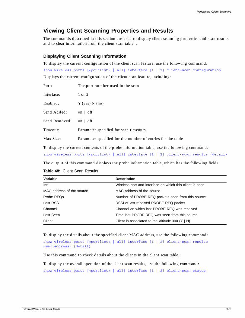
Performing Client Scanning
ExtremeWare 7
Viewing Client Scanning Properties and ResultsThe commands described in this section are used to display client scanning properties and scan results and to clear information from the client scan table. .
Displaying Client Scanning Information
To display the current configuration of the client scan feature, use the following command:
show wireless ports [<portlist> | all] interface [1 | 2] client-scan configuration
Displays the current configuration of the client scan feature, including:
Port: The port number used in the scan
Interface: 1 or 2
Enabled: Y (yes) N (no)
Send Added: on | off
Send Removed: on | off
Timeout: Parameter specified for scan timeouts
Max Size: Parameter specified for the number of entries for the table
To display the current contents of the probe information table, use the following command:
show wireless ports [<portlist> | all] interface [1 | 2] client-scan results {detail}
The output of this command displays the probe information table, which has the following fields:
To display the details about the specified client MAC address, use the following command:
show wireless ports [<portlist> | all] interface [1 | 2] client-scan results <mac_address> {detail)
Use this command to check details about the clients in the client scan table.
To display the overall operation of the client scan results, use the following command:
show wireless ports [<portlist> | all] interface [1 | 2] client-scan status
Table 48: Client Scan Results
Variable Description
Intf Wireless port and interface on which this client is seen
MAC address of the source MAC address of the source
Probe REQs Number of PROBE REQ packets seen from this source
Last RSS RSSI of last received PROBE REQ packet
Channel Channel on which last PROBE REQ was received
Last Seen Time last PROBE REQ was seen from this source
Client Client is associated to the Altitude 300 (Y | N)
.3e User Guide 373

Wireless Networking
The output of this command displays the performance results for the following variables on a per wireless interface basis.
Clearing Client Scanning Information
To clear the statistics associated with a particular client or with all clients, use the following command:
clear wireless ports [<portlist> | all] interface [1 | 2] client-scan counters [<hexoctet> | all]
Use this command to clear client scan counters on any interface: 1 or 2.
To clear the contents of the client scan information table or for a specific client MAC address, use the following command:
clear wireless ports [<portlist> | all] interface [1 | 2] client-scan results [<hexoctet> | all]
Use this command to clear the client scan results on any interface: 1 or 2.
Collecting Client History Statistics
Client information is collected from stations when sending frames to the Altitude 300. Based on the frames the client exchanges with the Altitude 300, three types of information are collected. These types are listed below:
• Current state: Current condition of the client. It is limited to clients that have sent this station an authentication request.
• MAC layer: Information about the operation of the MAC transport layer as it affects this particular client. This information can be used to detect problems with Altitude 300 placement, link utilization, etc.
• Historical information: View of a station through time. State transitions are preserved through a series of counters. This information can be used to debug various configuration problems.
Client Current StateClient current state information is available for all clients that have sent an authentication message to the Altitude 300. Information in this table is timed out if no packets have been received from the client by the configurable period of time set by the administrator.
Table 49: Client Scan Performance Results Per Wireless Interface
Variable Description
CurrentTableSize The current size of the table (in entries)
TableWatermark The maximum size the table has been since the last reset of the historical statistics
TotalOverflows The number of times an entry has been overwritten because the table is full
TotalTimeouts The number of times an entry has been aged out from the table
LastElement The last time an element was added to the table
TotalProbes The total number of probes received on this interface
374 ExtremeWare 7.3e User Guide
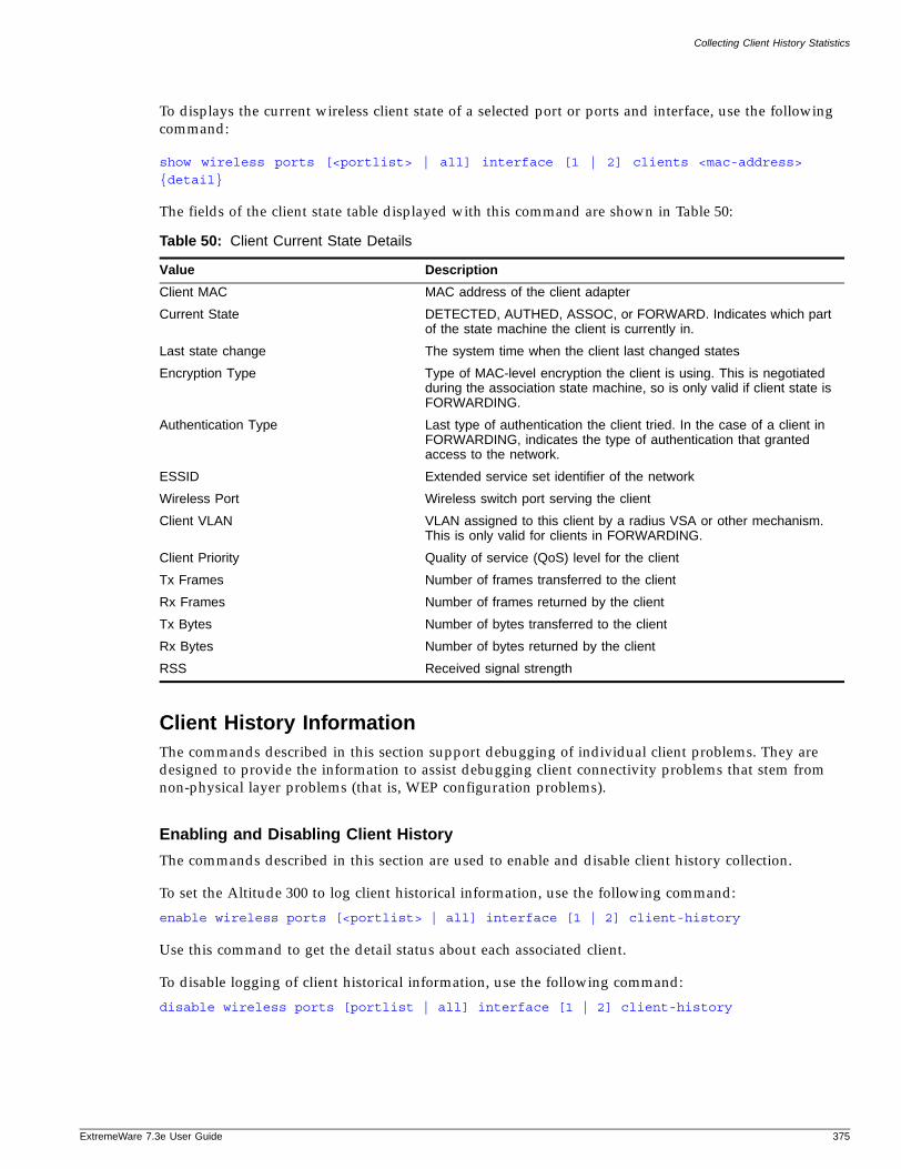
Collecting Client History Statistics
ExtremeWare 7
To displays the current wireless client state of a selected port or ports and interface, use the following command:
show wireless ports [<portlist> | all] interface [1 | 2] clients <mac-address>
{detail}
The fields of the client state table displayed with this command are shown in Table 50:
Client History InformationThe commands described in this section support debugging of individual client problems. They are designed to provide the information to assist debugging client connectivity problems that stem from non-physical layer problems (that is, WEP configuration problems).
Enabling and Disabling Client History
The commands described in this section are used to enable and disable client history collection.
To set the Altitude 300 to log client historical information, use the following command:
enable wireless ports [<portlist> | all] interface [1 | 2] client-history
Use this command to get the detail status about each associated client.
To disable logging of client historical information, use the following command:
disable wireless ports [portlist | all] interface [1 | 2] client-history
Table 50: Client Current State Details
Value Description
Client MAC MAC address of the client adapter
Current State DETECTED, AUTHED, ASSOC, or FORWARD. Indicates which part of the state machine the client is currently in.
Last state change The system time when the client last changed states
Encryption Type Type of MAC-level encryption the client is using. This is negotiated during the association state machine, so is only valid if client state is FORWARDING.
Authentication Type Last type of authentication the client tried. In the case of a client in FORWARDING, indicates the type of authentication that granted access to the network.
ESSID Extended service set identifier of the network
Wireless Port Wireless switch port serving the client
Client VLAN VLAN assigned to this client by a radius VSA or other mechanism. This is only valid for clients in FORWARDING.
Client Priority Quality of service (QoS) level for the client
Tx Frames Number of frames transferred to the client
Rx Frames Number of frames returned by the client
Tx Bytes Number of bytes transferred to the client
Rx Bytes Number of bytes returned by the client
RSS Received signal strength
.3e User Guide 375
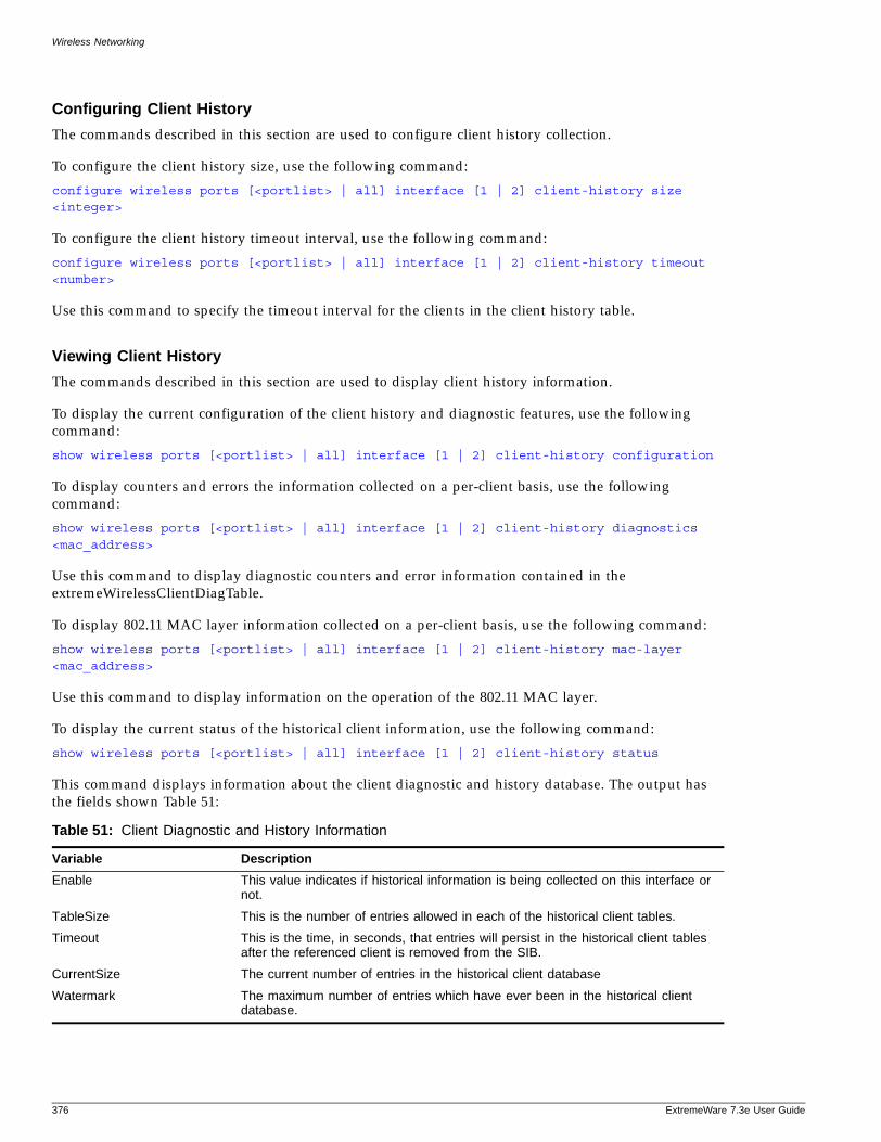
Wireless Networking
Configuring Client History
The commands described in this section are used to configure client history collection.
To configure the client history size, use the following command:
configure wireless ports [<portlist> | all] interface [1 | 2] client-history size <integer>
To configure the client history timeout interval, use the following command:
configure wireless ports [<portlist> | all] interface [1 | 2] client-history timeout <number>
Use this command to specify the timeout interval for the clients in the client history table.
Viewing Client History
The commands described in this section are used to display client history information.
To display the current configuration of the client history and diagnostic features, use the following command:
show wireless ports [<portlist> | all] interface [1 | 2] client-history configuration
To display counters and errors the information collected on a per-client basis, use the following command:
show wireless ports [<portlist> | all] interface [1 | 2] client-history diagnostics <mac_address>
Use this command to display diagnostic counters and error information contained in the extremeWirelessClientDiagTable.
To display 802.11 MAC layer information collected on a per-client basis, use the following command:
show wireless ports [<portlist> | all] interface [1 | 2] client-history mac-layer <mac_address>
Use this command to display information on the operation of the 802.11 MAC layer.
To display the current status of the historical client information, use the following command:
show wireless ports [<portlist> | all] interface [1 | 2] client-history status
This command displays information about the client diagnostic and history database. The output has the fields shown Table 51:
Table 51: Client Diagnostic and History Information
Variable Description
Enable This value indicates if historical information is being collected on this interface or not.
TableSize This is the number of entries allowed in each of the historical client tables.
Timeout This is the time, in seconds, that entries will persist in the historical client tables after the referenced client is removed from the SIB.
CurrentSize The current number of entries in the historical client database
Watermark The maximum number of entries which have ever been in the historical client database.
376 ExtremeWare 7.3e User Guide
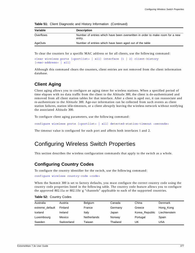
Configuring Wireless Switch Properties
ExtremeWare 7
To clear the counters for a specific MAC address or for all clients, use the following command:
clear wireless ports [<portlist> | all] interface [1 | 2] client-history [<mac-address> | all]
Although this command clears the counters, client entries are not removed from the client information database.
Client AgingClient aging allows you to configure an aging timer for wireless stations. When a specified period of time elapses with no data traffic from the client to the Altitude 300, the client is de-authenticated and removed from all client station tables for that interface. After a client is aged out, it can reassociate and re-authenticate to the Altitude 300. Age-out information can be collected from such events as client station failures, station idle-timeouts, or a client abruptly leaving the wireless network without notifying the associated Altitude 300.
To configure client aging parameters, use the following command:
configure wireless ports [<portlist> | all] detected-station-timeout <seconds>
The timeout value is configured for each port and affects both interfaces 1 and 2.
Configuring Wireless Switch Properties
This section describes the wireless configuration commands that apply to the switch as a whole.
Configuring Country CodesTo configure the country identifier for the switch, use the following command:
configure wireless country-code <code>
When the Summit 300 is set to factory defaults, you must configure the correct country code using the country code properties listed in the following table. The country code feature allows you to configure the approved 802.11a or 802.11b/g “channels” applicable to each of the supported countries.
Overflows Number of entries which have been overwritten in order to make room for a new entry.
AgeOuts Number of entries which have been aged out of the table
Table 52: Country Codes
Australia Austria Belgium Canada China Denmark
extreme_default Finland France Germany Greece Hong_Kong
Iceland Ireland Italy Japan Korea_Republic Liechtenstein
Luxembourg Mexico Netherlands Norway Portugal Spain
Sweden Switzerland Taiwan Thailand UK USA
Table 51: Client Diagnostic and History Information (Continued)
Variable Description
.3e User Guide 377
Wireless Networking
Extreme Networks ships the Summit 300 to be programmed with Extreme Network's special extreme_default country code, which brings up only the B/G radio in channel 6, and turns off the A radio. When an Altitude 300 wireless port is connected and the Summit 300 switch is unable to determine the country for which the Altitude is programmed, then the extreme_default country code is used. You must program the country code on the Summit 300 switch to enable the remaining channels for the desired country.
The Altitude 300 wireless port is shipped with a pre-programmed code for the following countries:
• North America (United States, Canada, Hong Kong)
• Japan
• Taiwan
• European Union and the Rest of the World.
If you do not program the country code in the Summit 300, then the switch inherits the country code of the first Altitude 300 wireless port that connects to it, if the Altitude is not programmed for the 'European Union and the Rest of World.
If there is a mismatch between the country codes between the Altitude 300 wireless port and the code programmed on the Summit 300 the Altitude 300 wireless port is not allowed to come up.
Configuring the Default Gateway
To configure the default gateway IP address, use the following command:
configure wireless default-gateway <ip_address>
The wireless default gateway IP address is usually set to the wireless management VLAN address. This address is used by all wireless client traffic whose destination is upstream switches.
Configuring the Management VLAN
To identify the VLAN on which the Altitude 300 wireless port communicates with the switch, use the following command:
configure wireless management-vlan <vlan name>
Identifying the VLAN on which the Altitude 300 wireless port communicates with the switch is required before wireless features can work. This VLAN can be the default VLAN and it can either have a public or private IP address. This VLAN is a tagged or untagged VLAN on which all the Altitude 300 devices are connected to untagged ports.
Configuring Wireless Ports
This section describes the wireless configuration commands that apply to a particular port or set of ports.
Enabling and Disabling Wireless PortsThe commands described in this section are used to enable and disable wireless port properties.
378 ExtremeWare 7.3e User Guide
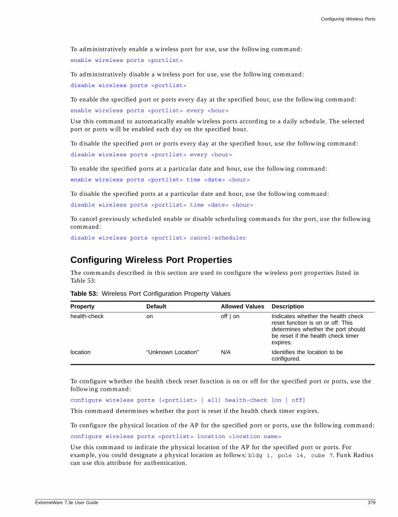
Configuring Wireless Ports
ExtremeWare 7
To administratively enable a wireless port for use, use the following command:
enable wireless ports <portlist>
To administratively disable a wireless port for use, use the following command:
disable wireless ports <portlist>
To enable the specified port or ports every day at the specified hour, use the following command:
enable wireless ports <portlist> every <hour>
Use this command to automatically enable wireless ports according to a daily schedule. The selected port or ports will be enabled each day on the specified hour.
To disable the specified port or ports every day at the specified hour, use the following command:
disable wireless ports <portlist> every <hour>
To enable the specified ports at a particular date and hour, use the following command:
enable wireless ports <portlist> time <date> <hour>
To disable the specified ports at a particular date and hour, use the following command:
disable wireless ports <portlist> time <date> <hour>
To cancel previously scheduled enable or disable scheduling commands for the port, use the following command:
disable wireless ports <portlist> cancel-scheduler
Configuring Wireless Port PropertiesThe commands described in this section are used to configure the wireless port properties listed in Table 53:
To configure whether the health check reset function is on or off for the specified port or ports, use the following command:
configure wireless ports [<portlist> | all] health-check [on | off]
This command determines whether the port is reset if the health check timer expires.
To configure the physical location of the AP for the specified port or ports, use the following command:
configure wireless ports <portlist> location <location name>
Use this command to indicate the physical location of the AP for the specified port or ports. For example, you could designate a physical location as follows: bldg 1, pole 14, cube 7. Funk Radius can use this attribute for authentication.
Table 53: Wireless Port Configuration Property Values
Property Default Allowed Values Description
health-check on off | on Indicates whether the health check reset function is on or off. This determines whether the port should be reset if the health check timer expires.
location “Unknown Location” N/A Identifies the location to be configured.
.3e User Guide 379
Wireless Networking
To reset selected wireless ports to their default values, use the following command:
reset wireless ports <portlist>
Use this command to return a port the default values. (See Table 53 for default values.)
Force disassociation permits client user disassociation based on a recurring schedule, a date and time, or a particular MAC address. You can also disassociate a user immediately. You can specify access based on a preferred time periods, such as during off-hours, weekends, and holidays. You can also set up a user policy on a RADIUS server to allow user authentication based on time of day.
To configure the client force-disassociation capability, use the following command:
configure wireless ports <portlist> force-disassociation [all-clients [every <hour <0-23>> <minute <0-59>> | time <month <1-12>> <day> <year <yyyy>> <hour <0-23>> <minute <0-59>>] | cancel-scheduler | <mac-address>]
Configuring Wireless Interfaces
Each wireless port on the Summit 300 switch contains two interfaces. Interface 1 (A radio) supports 802.11a, and interface 2 (B radio) supports 802.11b and 802.11g radio signals. The configure wireless interface commands allow you to configure one of the two individual interfaces (1|2) on a port or ports. You can move an interface from one profile to another without having to shut it down.
Enabling and Disabling Wireless InterfacesThe commands described in this section are used to enable and disable wireless port interface properties.
To enable a specified port interface, use the following command:
enable wireless ports <portlist> interface [1 | 2]\
To disable a specified port interface, use the following command:
disable wireless ports <portlist> interface [1 | 2]
Configuring Wireless InterfacesThe commands described in this section are used to configure wireless port interface properties.
To attach a port or ports and interface to an RF profile, use the following command:
configure wireless ports <portlist> interface [1 | 2] rf-profile <name>
All ports in the port list must have the same wireless port version.
To set the maximum number of clients that can connect simultaneously to a wireless interface, use the following command:
configure wireless ports [<portlist> | all] interface [1 | 2] max-clients <value>
Valid max-client values range from 0 (zero) to 128.
To configure the power-level for a specified interface, use the following command:
configure wireless ports <portlist> interface [1 | 2] power-level <level>
380 ExtremeWare 7.3e User Guide
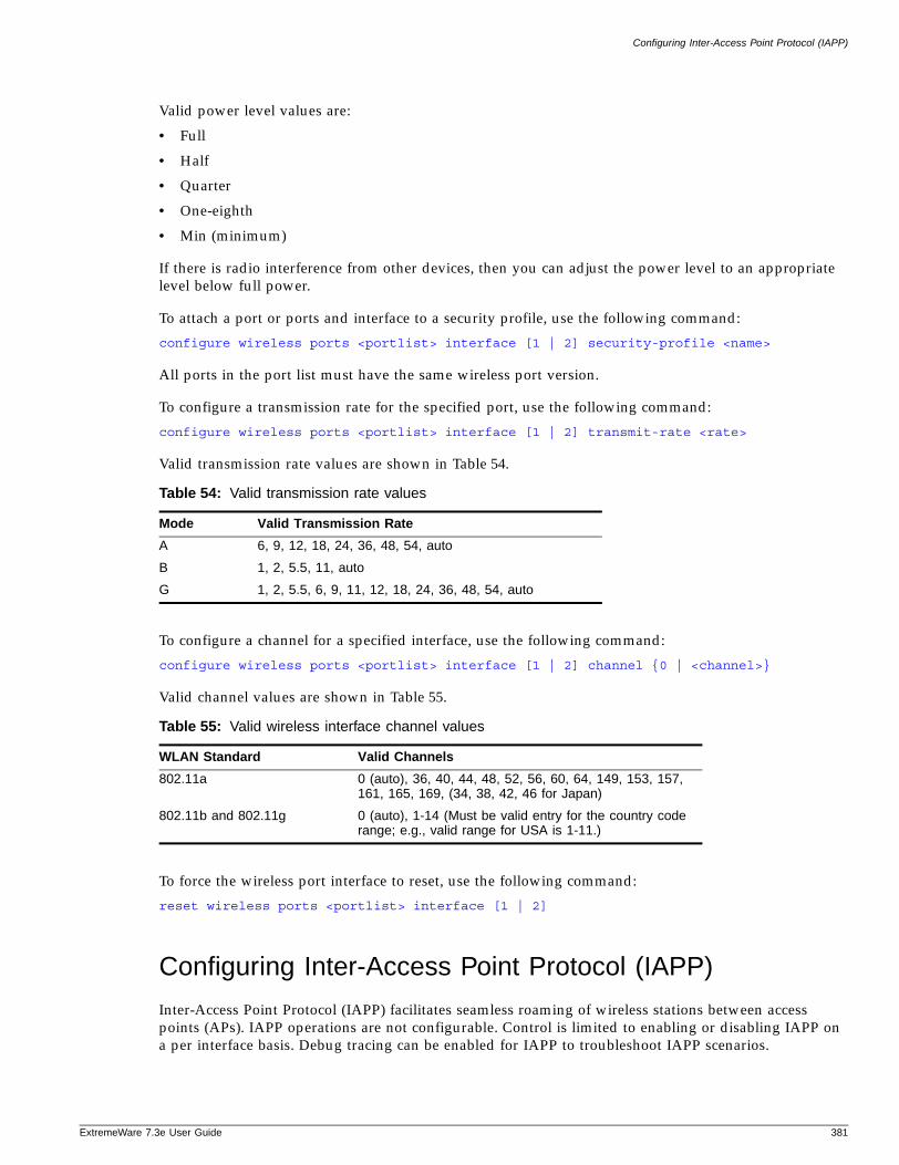
Configuring Inter-Access Point Protocol (IAPP)
ExtremeWare 7
Valid power level values are:
• Full
• Half
• Quarter
• One-eighth
• Min (minimum)
If there is radio interference from other devices, then you can adjust the power level to an appropriate level below full power.
To attach a port or ports and interface to a security profile, use the following command:
configure wireless ports <portlist> interface [1 | 2] security-profile <name>
All ports in the port list must have the same wireless port version.
To configure a transmission rate for the specified port, use the following command:
configure wireless ports <portlist> interface [1 | 2] transmit-rate <rate>
Valid transmission rate values are shown in Table 54.
To configure a channel for a specified interface, use the following command:
configure wireless ports <portlist> interface [1 | 2] channel {0 | <channel>}
Valid channel values are shown in Table 55.
To force the wireless port interface to reset, use the following command:
reset wireless ports <portlist> interface [1 | 2]
Configuring Inter-Access Point Protocol (IAPP)
Inter-Access Point Protocol (IAPP) facilitates seamless roaming of wireless stations between access points (APs). IAPP operations are not configurable. Control is limited to enabling or disabling IAPP on a per interface basis. Debug tracing can be enabled for IAPP to troubleshoot IAPP scenarios.
Table 54: Valid transmission rate values
Mode Valid Transmission Rate
A 6, 9, 12, 18, 24, 36, 48, 54, auto
B 1, 2, 5.5, 11, auto
G 1, 2, 5.5, 6, 9, 11, 12, 18, 24, 36, 48, 54, auto
Table 55: Valid wireless interface channel values
WLAN Standard Valid Channels
802.11a 0 (auto), 36, 40, 44, 48, 52, 56, 60, 64, 149, 153, 157, 161, 165, 169, (34, 38, 42, 46 for Japan)
802.11b and 802.11g 0 (auto), 1-14 (Must be valid entry for the country code range; e.g., valid range for USA is 1-11.)
.3e User Guide 381
Wireless Networking
To enable IAPP on a per interface basis, use the following command:
enable wireless ports [<portlist> | all] interface [1 | 2] iapp
IAPP uses layer 2 updates to allow connected layer 2 devices to update forwarding tables with the address of the client. The AP sends the updates on behalf of the clients by inserting the MAC address of the mobile station in the source address. The switch looks up the UDP request packet on the local subnet that contains the AP MAC address which contains the needed IP address. All APs on the subnet receive this message. The AP with the matching MAC address sends a unicast response packet with its IP address.
To disable IAPP on a per interface basis, use the following command:
disable wireless ports [<portlist> | all] interface [1 | 2] iapp
To enable debug tracing for IAPP on a per interface basis to troubleshoot IAPP scenarios, use the following command:
configure debug-trace wireless ports [<portlist> | all] iapp <debug-level>
The valid debug level range is 0 (off) to 5, corresponding to increasing levels of debug detail.
Event Logging and Reporting
The Summit 300 switch supports the following enhancements for wireless event logging and reporting with respect to the Altitude 300 local log, which is filtered on a per port basis:
• Enumerated type fields are included in syslog messages for filtering by external tools.
• An additional CLI command is included for more granularity, as described below
To display the local Altitude 300 event log of the selected port or ports, use the following command:
show wireless ports [<portlist>| all] {summary} log
You can use this command to display the Altitude 300 local log for debugging errors.
Enabling SVP to Support Voice Over IP
SpectraLink Voice Priority (SVP) is a voice over IP (VoIP) protocol that ensures acceptable audio quality in a mixed voice and data environment. It overcomes limitations of the 802.11 Standard by handling RTP packets between the SVP gateway and handset in a manner that is optimized for VoIP traffic over a wireless LAN (WLAN). SVP does this by:
• Prioritizing voice packets on the wireless network through a packet classification scheme based on the IP protocol number for SpectraLink Radio Protocol (119).
• Assigning filtered packets to high-priority outbound queues on each interface.
• Disabling random backoff for voice packets, setting the backoff window to zero.
• Queuing packets for Power Saving (PS) devices for the interval specified in the Listen Interval.
NOTE
Queued packets must be properly signaled in the TIM of Beacons. VoIP handsets must be able to enter PS mode by setting the PS bit in any uplink packet.
382 ExtremeWare 7.3e User Guide

Enabling SVP to Support Voice Over IP
ExtremeWare 7
SVP control is maintained at the virtual-interface level. It can be turned on or off for each virtual interface. A separate transmit queue for SVP packet handling should be maintained for each interface.
To enable the QoS protocol, SpectraLink Voice Protocol (SVP), for VoIP on the specified port and interface., use the following command:
enable wireless ports [<portlist> | all] interface [1 | 2] svp
To disable SVP for VoIP on the specified port and interface., use the following command:
disable wireless ports [<portlist> | all] interface [1 | 2] svp
.3e User Guide 383

Wireless Networking
384 ExtremeWare 7.3e User Guide
21 Power Over Ethernet
ExtremeWare 7
This chapter explains how to configure the Summit 300 to supply power to devices using the Power over Ethernet (PoE) capability. It contains the following sections:
• Overview on page 385
• Port Power Management on page 386
• Per-Port LEDs on page 393
• Configuring Power Over Ethernet on page 393
Overview
Power over Ethernet (PoE), defined by the IEEE 802.3af specification, is an effective method of supplying 48 VDC power to certain types of powered devices (PDs) by way of Category 5 or Category 3 twisted pair Ethernet cables. Devices include the Altitude 300 wireless port, IP telephones, laptop computers, web cameras, or other devices. With PoE, a single Ethernet cable supplies power and the data connection, thereby saving time and expense associated with separate power cabling and supply.
The 802.3af specification for PoE includes a method of detection to assure that power is delivered only to devices that meet the specification.
Summary of PoE FeaturesThe Summit 300 supports the following PoE features:
• Configuration and control of the power distribution for PoE at the system (slot) level
• Configuration and control of the power distribution for PoE at the port level
• Real time detection of powered devices on the line
• Monitor and control of fault conditions
• Support for configuring and monitoring PoE status at the port level
• Management of an over-subscribed power budget
• LED control for indicating the port “power” state
.3e User Guide 385
Power Over Ethernet
Port Power Management
When you connect PDs, the Summit 300 automatically discovers and classifies those that are AF-complaint. The following functions are supported for delivering power to the port:
• Enabling the port for discovery and classification
• Enabling power delivery to a discovered device
• Enforcing port power limits by denying power to a device that exceeds the power limit by more than approximately 10%
• Enforcing class limits by denying power to a device that exceeds the class limit
• Reporting and tracking port power faults
• Managing power budgets and allocation
• Managing port priorities
For detailed information about using the PoE command set to configure and manage PoE, see the ExtremeWare Software Command Reference Guide.
Port Power Operator Limit
Each port is configured by default. The power limit is set to the maximum of the operator limit and class. You can also specify a power limit on a per-port basis using the following command:
configure inline-power violation-precedence [advertised-class | operator-limit |
max-class-operator | none] ports <portlist>.
Power is allowed up to maximum limit (15.4 watts on the Summit 300-24 and 20 watts on the Summit 300-48). There are several options for defining a violation policy and creating a device fault:
• Class violation—Power is removed if the PD consumes more than the discovered class limit.
• Operator limit—Power is removed if the PD consumes more than the operator-specified limit. The PD is allowed to draw about 10% over the configured limit before power is shut off to the device.
• Maximum of operator limit and class—Power is removed if the PD consumes more than the operator limit or discovered class limit, whichever is greater.
• None—Power is removed if the device exceeds the maximum limit.
Power Budget Management
The Summit 300 software is responsible for managing overall power consumption to ensure that it does not attempt to delivery more power than is available. The Summit 300-24 has sufficient power budget to provide full 15.4 watts power on all 24 ports simultanously. The Summit 300-48 can operate half of the 48 ports at full power before requiring reserve power. You can configure how the Summit 300-48 switch allocates power to devices upon power-up and in the event that available power is reduced.
Reserved Power on the Summit 300-48
You can reserve power for devices connected to a specific port by using the following command:
configure inline-power reserved budget <milliwatts> ports <portlist>
386 ExtremeWare 7.3e User Guide
Port Power Management
ExtremeWare 7
Use the following command to specify that a user-defined limit applies the indicated port:
configure inline-power violation-precedence [advertised-class | operator-limit | max-class-operator | none] ports <portlist>
When a new device is discovered, its defined power requirement is first subtracted from the reserved power pool. If there is sufficient reserved power on the port, the device is powered. Otherwise the remaining power is subtracted from the common pool, and the device is powered if there is sufficient reserved plus common power available. Reserved power is subtracted from the common pool and unavailable to other ports. The total reserved power cannot exceed the total available power.
NOTE
A connected device may draw more power than the amount reserved, due to configuration error or oversight. The switch provides notification if this occurs.
Common Power Pool on the Summit 300-48 Only
The common power pool represents the total amount of power available on a per-slot basis, less any power reserved or allocated to currently powered devices. When a new device is discovered, its defined power requirements are subtracted from the common power pool. If the common pool does not have sufficient available power, power is not supplied to the device. In this case, the port is placed in a power-denied state. The device can be powered at a later time if more power becomes available to the common power pool due to another device disconnecting or if previously reserved power becomes available.
If multiple devices are in the denied state and more power becomes available, the devices are powered in order of priority and connection.
Port Connection Order (Summit 300-48 Only)
The Summit 300-48 switch software tracks the order of connection for powered devices. The connection order is recorded at the time a device is first discovered and classified. The connection order is reset if the device is disconnected. This connection order is maintained even if the switch is powered down or power is interrupted, and the device must be discovered again.
During system startup, ports are powered initially based only on the connection order. During normal system operations, port power order is determined first based upon priority, then discovery time. Thus, the highest priority port with the earliest discovery time is powered first.
You can view the connection history for a selected port by using the following command:
show inline-power info [detail] port <portlist]
You can view the port connection order for a selected slot on the Summit 300-48 by using the following command:
show inline-power stats slot <slotlist>
You can clear the connection history for a selected slot on the Summit 300-48 by using the following command:
clear inline-power connection-history slot <slot_number>
.3e User Guide 387

Power Over Ethernet
Port Power Priorities (Summit 300-48 only)
You can set the priority of a port to low, high, or critical by using the following command:
configure inline-power priority [low | high | critical] ports <portlist>
Higher priority ports are given precedence in powering sequence.
Port Power Reset
You can set ports to experience a power-down, discover, power-up cycle without returning the power to the common pool. This allows you to reset powered devices without losing their claim to the common power pool or connection order.
The following command power cycles the specified ports:
reset inline-power ports <portlist>
Ports are immediately powered off and powered on, maintaining current power allocations.
Port Power Budgets
The standard 802.3af protocol permits a PD to be classified into one of 5 classes, each of which determines the maximal power draw to the power sourcing equipment (PSE). Extreme PSEs, in the default configuration, use the classification-to-power draw in performing power management and budgeting.
Classification is optional, and many PD devices do not support it. Therefore, under normal conditions, the Extreme PSE budgets for the maximum permitted power (15.4 watts), even though the maximum device draw may be less. This may cause fewer devices to be powered, since the power budget is prematurely exhausted. There is a wide variation in power consumption levels between 802.3af classes (~8 watts). In such cases, the power level limit (operator-limit) can be set on a per port basis. If this is done, the operator limit, rather than the discovered class limit will be used for power budgeting. It is also necessary for the violation-precedence to be set to operator-limit.
Regardless of how the port power limit is derived (through automatic classification or operator limit), the port power limit is used to determine whether the overall system limit has been exceeded. Once the overall system limit is reached, additional PoE ports are powered based on the system violation-precedence setting and port power priority.
The power port limit is also used during system operation to limit the power supplied to each PoE port. If a powered device attempts to draw more power than has been budgeted, the chassis will remove power from that port to prevent system overload or device damage.
NOTE
The operator set limit must be based upon the device manufacturer's specified maximal power draw. It must not be derived from measured device power consumption, since the power draw typically fluctuates. The operator limit allows the device to draw about 10% more than the configured limit before power is shut off to the device.
Use the folowing command to set the maximum power available for PDs on a per port basis:
388 ExtremeWare 7.3e User Guide
Port Power Management
ExtremeWare 7
configure inline-power operator-limit <milliwatts> ports <portlist>
To reset the operator limit back to the default value, use the following command:
unconfigure inline-power operator-limit ports <portlist>
Use the following command to specify that a user-defned limit applies the indicated port.
configure inline-power violation-precedence [advertised-class | operator-limit | max-class-operator | none] ports <portlist>
Likewise, to reset the violation precedence to the default value of max-class-operator, enter this command:
unconfigure inline-power violation-precedence ports <portlist>
Port Power Budget Example:
Assume that a PD device maximal draw is 9W based on the manufacturer's specification. Such a device, if classified, would be considered to be in class 3, and under the default configuration, would be budgeted to draw 15.4 watts.
To budget the power based on 9W, enter the following configuration. It is assumed that the device will be connected to slot 1, port 1, with budget is set to 10W, allowing a small tolerance above manufacturer specification.
Summit300# disable inline-power ports 1:1Summit300# config inline-power operator-limit 10000 port 1:1Summit300# config inline-power violation-precedence operator-limit port 1:1
Port Power Events
If a port has sufficient reserved power for a newly discovered and classified device, the device receives power. If additional power is required and the common pool has sufficient available power, the device is powered and the incremental power is subtracted from the common pool. If the port does not have reserved power, but sufficient power is available from the common pool, the power is subtracted from the pool.
Port power budget is determined based upon the maximum class power levels or operator specification, not actual consumed power. For example, if a port is configured with an operator limit of 15.4 watts and the violation precedence is set to the operator limit, then 15.4 watts is budgeted for the port even if a 5 watt 802.3af compliant device is connected.
If a sufficient mix of reserved and common power is not available, the port enters a denied state and is not given power.
Ports are powered based upon their priority and discovery time. Higher priority ports with the oldest discovery time are powered first.
If a device consumes more power than it is allocated by class type, it is considered a class violation. The device enters a fault state, and unreserved power is returned to the common pool. Power is also returned to the common pool if a port is disconnected. The device stays in the fault state until you explicitly clear the fault or disable the port for power.
.3e User Guide 389
Power Over Ethernet
Supporting Legacy Devices on the Summit 300-24The Summit 300-24 is capable of powering devices that are compliant to the IEEE 802.3af Power over Ethernet standard. The enable inline-power legacy command allows PoE devices build before the standard was approved to be powered.
If all the devices connected to the switch are 802.3af standards compliant, it is advised to keep the default setting of disabled for legacy device support. To return legacy support to the default setting of disabled, enter the following command:
disable inline-power legacy
You can determine whether a device connected to the switch is standands compliant or not by using the show inline-power info [detail] port <portlist] command. The detailed status line shows if the device is 802.3af standards compliant.
Sample output from the show inline-power info detail ports commmand follows:
Summit300-24:3 # show inline-power info detail ports 5
PORT - 5
Configured Admin State: Enabled Inline Power State: delivering MIB Detect Status: delivering Label: Violation Precedence: max-class-operator Operator Limit: 15400 milliwatts Inline Type: other PD Class: class3 Max Allowed Power: 15.400 W Measured Power: 6.90 W Line Voltage: 50.2 Volts Current: 117 mA Fault Status: None (D 0) Detailed Status: valid resistor detected, 802.3af-compliant PD was detected
Using Power SuppliesThe Summit 30-24 supports and internal power supply that can provide 15.4 W AC to all 24 ports. An external 465 W AC power supply is available to provide redundant power. The Summit 300-48 supports only internal power supplies for either redundant or load sharing modes.
Redundant Power Supply (Summit 300-24 only)
The Extreme Networks External Power Supply 45019 (EPS-LD) provides additional power to the Summit 300-24. The EPS-LD provides 465 W total power with 375 W dedicated for PoE applications. When attached to the Summit 300-24, the EPS-LD acts as a redundant power supply. The wattage is sufficient to power all ports on the Summit 300-24 model.
Load Sharing Power Supplies (Summit 300-48 only)
The PoE subsystem supports dual power supplies for either redundant or load-sharing modes. Redundant mode is the default and provides hitless PoE should one of the two power supplies fail, be removed, or powered off. Load-sharing mode allows both power supplies to provide power to the PoE
390 ExtremeWare 7.3e User Guide
Port Power Management
ExtremeWare 7
system, providing greater PoE power capacity. For load-sharing operation, the amount of power provided to the PoE system is the sum of the power supplied by the power supplies.
NOTE
With load-sharing, all PoE devices may experience a power hit if a power supply fails.
ExtremeWare 7.3e supports a 600 W AC power supply unit (PSU), which is identical to the existing PSU except that it provides 600 W of power. To determine the wattage of the installed PSUs when the PSUs are in redundant mode, use the show inline-power command. If System maximum internal inline-power field indicates 480 W, that means that 600 W PSUs are installed.
ExtremeWare 7.3 provides new firmware to support an advanced PoE controller. Previous versions of ExtremeWare 6.2a.1 cannot be used on Summit 300es containing the new PoE controller. If you attempt to install previous versions on a switch containing the new controller, an error similar to the following is generated:
!Image doesn't support this
hardware ERROR
Redundant Operation
For redundant operation, the amount of power provided to the PoE system is the minimum wattage supplied by either supply. If a power supply fails or is removed, power to the PoE system is unaffected; thus powered devices do not experience a power loss.
Load-Sharing Operation
For load-sharing operation, the amount of power provided to the PoE system is the sum of the power supplied by the power supplies. The maximum amount of power provided is listed in Table 56.
The total power used by all PoE devices must not exceed the total available inline power indicated in Table 56. If the power used exceeds the total available, power for all devices is removed. To plan for the total power load, use the PoE device manufacturer’s maximum power use specifications. Use the configure inline-power command to set a lower available inline power, set a limit to the amount of power available to a specific port, or set the precedence of ports if power is removed.
Table 56: Power supplies
Power Supplies Installed Mode Total Available Inline Power
Two 600 W Redundant 450 W
Two 600 W Load-sharing 480 W
One 600 W N/A 450 W
One 400 W, one 600 W Redundant 306 W
One 400 W, one 600 W Load-sharing 480 W
Two 400 W Redundant 306 W
Two 400 W Load-sharing 480 W
One 400 W N/A 306 W
.3e User Guide 391
Power Over Ethernet
NOTE
Do not use the output of the show inline-power command for planning. This output is a snapshot of current power consumption and does not reflect the maximum power use possible.
If a power supply fails or is removed and the current draw of the attached devices exceeds the power supplied by the remaining power supply, the power for all devices is removed and all devices experience a power loss. After power is restored, the PoE system re-enables power to devices until the supply limit is reached. This is likely to be the single supply limit, and previously powered devices might not be repowered.
Changing Modes (Summit 300-48 Switch Only)
Changing power supply modes from load-sharing to redundant requires first disabling inline power on ports, as with other configuration commands. Changing from redundant to load-sharing is allowed without disabling inline power, as this potentially increases the inline power available to the system.
To select the power supply operating mode, enter this command:
configure inline-power power-supply [redundant | load-sharing]
To return the configuration to the default value of redundant, enter this command:
unconfigure inline-power power-supply
To reset a specific slot on the Summit 300-48, enter this command:
reset inline-power slot <slot number>
The power supply mode configuration affects the configuration settings as outlined in Table 57. The operator is responsible for correct system configuration. Changes between load-sharing and redundant modes resulting in invalid configurations will be rejected.
The power supply mode configuration affects the configuration settings as outlined in Table 57. The operator is responsible for correct system configuration. Changes between load-sharing and redundant modes resulting in invalid configurations will be rejected.
Table 57: Power Parameter Restrictions
Parameter Restriction
Slot Power Budget Cannot exceed configured card maximum capacity. System issues a warning if the sum of the slot budgets exceeds the PSU capacity (based on the PSU mode setting and installed power supplies). Configuration is not rejected.
Reserved-budget per Port The sum of the port reserved budgets cannot exceed the slot budget.
Table 58: Power Parameter Restrictions
Parameter Restriction
Slot Power Budget Cannot exceed configured card maximum capacity. System issues a warning if the sum of the slot budgets exceeds the PSU capacity (based on the PSU mode setting and installed power supplies). Configuration is not rejected.
392 ExtremeWare 7.3e User Guide
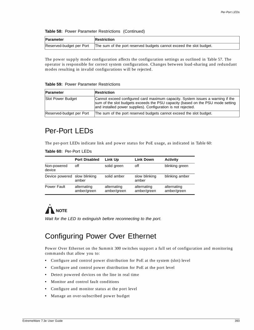
Per-Port LEDs
ExtremeWare 7
The power supply mode configuration affects the configuration settings as outlined in Table 57. The operator is responsible for correct system configuration. Changes between load-sharing and redundant modes resulting in invalid configurations will be rejected.
Per-Port LEDs
The per-port LEDs indicate link and power status for PoE usage, as indicated in Table 60:
NOTE
Wait for the LED to extinguish before reconnecting to the port.
Configuring Power Over Ethernet
Power Over Ethernet on the Summit 300 switches support a full set of configuration and monitoring commands that allow you to:
• Configure and control power distribution for PoE at the system (slot) level
• Configure and control power distribution for PoE at the port level
• Detect powered devices on the line in real time
• Monitor and control fault conditions
• Configure and monitor status at the port level
• Manage an over-subscribed power budget
Reserved-budget per Port The sum of the port reserved budgets cannot exceed the slot budget.
Table 59: Power Parameter Restrictions
Parameter Restriction
Slot Power Budget Cannot exceed configured card maximum capacity. System issues a warning if the sum of the slot budgets exceeds the PSU capacity (based on the PSU mode setting and installed power supplies). Configuration is not rejected.
Reserved-budget per Port The sum of the port reserved budgets cannot exceed the slot budget.
Table 60: Per-Port LEDs
Port Disabled Link Up Link Down Activity
Non-powered device
off solid green off blinking green
Device powered slow blinking amber
solid amber slow blinking amber
blinking amber
Power Fault alternating amber/green
alternating amber/green
alternating amber/green
alternating amber/green
Table 58: Power Parameter Restrictions (Continued)
Parameter Restriction
.3e User Guide 393
Power Over Ethernet
Use the inline power commands described in the following sections to configure PoE on Summit 300 ports. For detailed information about using the PoE command set to configure and manage PoE, see the ExtremeWare 7.3e Command Reference Guide.
Controlling and Monitoring System and Slot PowerUse the general switch management commands described in this section to control and monitor power at the system level and slot level. The main power supply information and settings apply to the system. System power to the PoE controller is provided by the main PSU that provides power, temperature, and fan monitoring status.
Configuring System and Slot Power
Before any port can be powered, the system must be enabled for power and the slot on which the port resides must be enabled for power. Ultimately, the port must also be enabled for power. The PoE command set lets you configure inline power at the system and slot levels. You can perform the following configuration and maintenance tasks at the system and slot levels:
• Control inline power to the system
• Control inline power to selected slots
• Set a power usage alarm threshold
• Configure a backup power source for the 48V external power supply
• Replace the firmware
• Clear the port connection history for a slot
NOTE
Configuration parameters affecting operational parameters require the port or slot to be first disabled.
Controlling Inline Power to the System. You can control whether inline power is provided to the system through a set of enabling and disabling commands. Use the following command to enable inline power provided to the system:
enable inline-power
Disabling inline power to the system shuts down power currently provided on all slots and all ports in the system. Use the following command to disable inline power to the system:
disable inline-power
Controlling Inline Power to Slots on the Summit 300-48 only. You can control whether inline power is provided to selected slots through a set of enabling and disabling commands. Use the following command to enable inline power provided to a particular slot:
enable inline-power slot <slot_id>
Disabling inline power to selected slots shuts down power currently provided on those slots and all ports in those slots. Use the following command to disable inline power to a particular slot:
disable inline-power slot <slot_id>
Setting a Power Usage Alarm Threshold. You can set an alarm threshold to issue a warning if system power levels exceed that limit. The limit is expressed as a percentage of measured power to
394 ExtremeWare 7.3e User Guide
Configuring Power Over Ethernet
ExtremeWare 7
available power. The alarm threshold is shared between the system level utilization and the allocated power budget per slot. (See the configure inline-power reserved budget <milliwatts> ports <portlist> command.) A warning is issued if either level exceeds the threshold level set by the following command:
configure inline-power usage-threshold <threshold>
To reset the power usage alarm threshold to the default value of 70%, use the following command:
unconfigure inline-power usage-threshold
Clearing Port Connection History for a Slot on the Summit 300-48 only. You can clear the port connection history for a specified slot by using the following command:
clear inline-power connection-history slot
Monitoring System and Slot Power
The PoE command set lets you view inline power status for the system and selected slots. You can view the following information:
• System power status
• Slot power status
• Slot power configuration
• Slot power statistics
Displaying System Power Status. Use the following command to view global inline power information for the system:
show inline-power
The output indicates the following inline power status information for the system:
• System maximum inline power—The nominal power available, in watts.
• Configured System Power Usage—The configured power usage threshold for the system, shown in watts and as a percentage of available power.
Following is sample output from this command:
Inline Power System InformationSystem maximum inline-power: 32 wattsPower Usage: 70% (22 watts)
Slot Main PSU Status Backup PSU Status Firmware Status1 OFF Present, ACTIVATED Operational
Displaying Slot Power Configuration on the Summit 300-48. Use the following command to view inline power configuration information for the specified slots:
show inline-power configuration slot <slotlist>
• Status—Indicates power status:
— Enabled: The slot is available to provide power.
— Disabled: The slot is not available to provide power.
.3e User Guide 395
Power Over Ethernet
• Cfg PSU Backup—Indicates the current setting of power source precedence:
— Internal
— None
• PSU Active—Indicates the power source currently supplying power:
— Internal
— External
• Usage Threshold—Displays the configured alarm threshold as a percentage.
• Connection Order—Displays the list of ports (1 – 32) by current connection order.
Following is sample output from this command:
Slot Status Cfg PSU Backup PSU Active Usage Threshold1 Enabled Internal Internal 70%
Displaying Slot Power Statistics. Use the following command to view inline power statistics for the specified slots:
show inline-power stats slot <slotlist>
• This command lets you view how many ports are faulted, powered, and waiting for power for the slot. It also lists ports by current connection order.
The following is sample output from this command from a Summit 300-48. Output from a Summit 300-24 differs slightly.
PoE firmware status: OperationalPoE firmware revision: 1.6Connection Order: 3 15Total ports powered: 1Total ports waiting for power: 0Total ports faulted: 0Total ports disabled: 1
Controlling and Monitoring Port PowerUse the commands described in this section to control and monitor power at the port level. Before any port can be powered, the system must be enabled for power and the slot on which the port resides must be enabled for power. Ultimately, the port must also be enabled for power.
Configuring Port Power
The PoE command set lets you configure inline power at the system and slot levels. (See “Configuring System and Slot Power” on page 394.) Power control is also provided on a per port basis. You can perform the following configuration and maintenance tasks for selected ports:
• Control inline power.
• Control the power detection mechanism.
• Set the power limit.
• Set the violation precedence.
• Set the reserved power level.
396 ExtremeWare 7.3e User Guide
Configuring Power Over Ethernet
ExtremeWare 7
• Power cycle.
• Clear fault conditions.
• Create user-defined labels.
Controlling Inline Power to Ports. You can control whether inline power is provided to selected ports through a set of enabling and disabling commands. Use the following command to enable inline power provided to selected ports:
enable inline-power ports <portlist>]
Disabling inline power to selected ports shuts down power currently provided to those ports. Disabling a port providing power to a powered device (PD) will immediately remove power to the PD. The system defaults to enabling power on all 10/100 ports. Use the following command to disable inline power to the system:
disable inline-power ports <portlist>]
Controlling the Power Detection Mechanism for Selected Ports on the Summit 300-48. You can control the power detection mechanism for selected ports by using the following command:
configure inline-power detection [auto | discovery-test-only] ports <portlist>
Test mode forces power discovery operations; however, power is not supplied to detected PDs.
To reset the power detection scheme to the default, use the following command:
unconfigure inline-power detection ports <portlist>
Setting the Reserved Power Level for Selected Ports on the Summit-300-48. You can set the reserved power for selected ports by using the following command:
configure inline-power budget <watts> slot <slot_number>
You can specify the default value (0 mW) or you can set the reserved power wattage in the range of 0 or 3000 – 20000 mW. The total power reserved may be up to but not greater than the total power for the module. If all the power available to the module is reserved, then the common power pool is empty.
To reset the reserved budget to the default value, use the following command:
unconfigure inline-power reserved-budget ports <portlist>
Power Cycling Selected Ports. You can power cycle selected ports by using the following command:
reset inline-power ports <portlist>
Ports are immediately de-powered and re-powered, maintaining current power allocations.
Clearing Fault Conditions and Statistics for Selected Ports. Use the following command to clear the fault condition on the selected ports:
clear inline-power fault ports <portlist>
Use the following command to clear inline statistics for a selected ports:
clear inline-power stats <portlist>
.3e User Guide 397
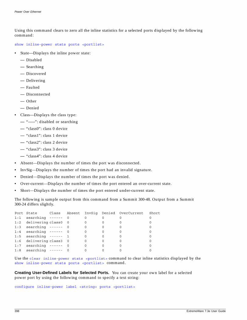
Power Over Ethernet
Using this command clears to zero all the inline statistics for a selected ports displayed by the following command:
show inline-power stats ports <portlist>
• State—Displays the inline power state:
— Disabled
— Searching
— Discovered
— Delivering
— Faulted
— Disconnected
— Other
— Denied
• Class—Displays the class type:
— “-----”: disabled or searching
— “class0”: class 0 device
— “class1”: class 1 device
— “class2”: class 2 device
— “class3”: class 3 device
— “class4”: class 4 device
• Absent—Displays the number of times the port was disconnected.
• InvSig—Displays the number of times the port had an invalid signature.
• Denied—Displays the number of times the port was denied.
• Over-current—Displays the number of times the port entered an over-current state.
• Short—Displays the number of times the port entered under-current state.
The following is sample output from this command from a Summit 300-48. Output from a Summit 300-24 differs slightly.
Port State Class Absent InvSig Denied OverCurrent Short1:1 searching ------ 0 0 0 0 01:2 delivering class0 0 0 0 0 01:3 searching ------ 0 0 0 0 01:4 searching ------ 0 0 0 0 01:5 searching ------ 1 0 0 0 01:6 delivering class3 0 0 0 0 01:7 searching ------ 0 0 0 0 01:8 searching ------ 0 0 0 0 0
Use the clear inline-power stats <portlist> command to clear inline statistics displayed by the show inline-power stats ports <portlist> command.
Creating User-Defined Labels for Selected Ports. You can create your own label for a selected power port by using the following command to specify a text string:
configure inline-power label <string> ports <portlist>
398 ExtremeWare 7.3e User Guide
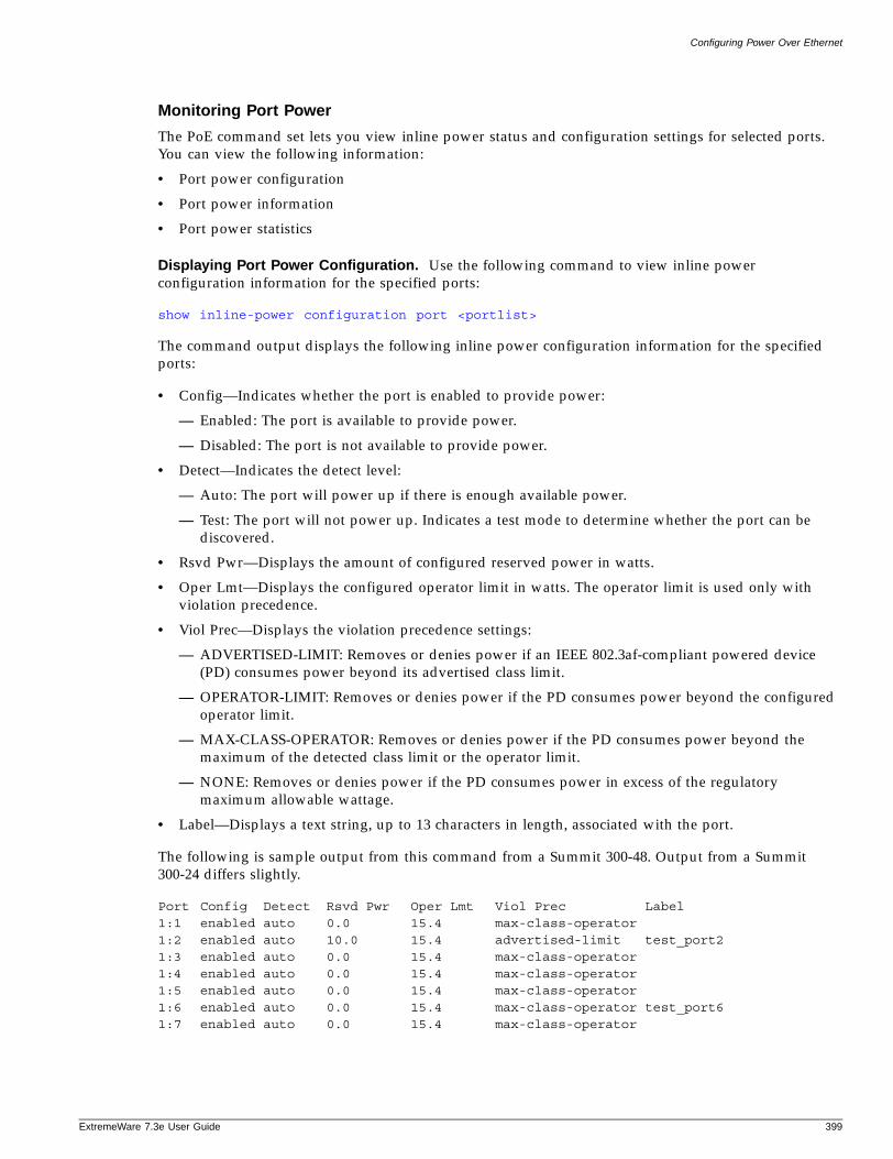
Configuring Power Over Ethernet
ExtremeWare 7
Monitoring Port Power
The PoE command set lets you view inline power status and configuration settings for selected ports. You can view the following information:
• Port power configuration
• Port power information
• Port power statistics
Displaying Port Power Configuration. Use the following command to view inline power configuration information for the specified ports:
show inline-power configuration port <portlist>
The command output displays the following inline power configuration information for the specified ports:
• Config—Indicates whether the port is enabled to provide power:
— Enabled: The port is available to provide power.
— Disabled: The port is not available to provide power.
• Detect—Indicates the detect level:
— Auto: The port will power up if there is enough available power.
— Test: The port will not power up. Indicates a test mode to determine whether the port can be discovered.
• Rsvd Pwr—Displays the amount of configured reserved power in watts.
• Oper Lmt—Displays the configured operator limit in watts. The operator limit is used only with violation precedence.
• Viol Prec—Displays the violation precedence settings:
— ADVERTISED-LIMIT: Removes or denies power if an IEEE 802.3af-compliant powered device (PD) consumes power beyond its advertised class limit.
— OPERATOR-LIMIT: Removes or denies power if the PD consumes power beyond the configured operator limit.
— MAX-CLASS-OPERATOR: Removes or denies power if the PD consumes power beyond the maximum of the detected class limit or the operator limit.
— NONE: Removes or denies power if the PD consumes power in excess of the regulatory maximum allowable wattage.
• Label—Displays a text string, up to 13 characters in length, associated with the port.
The following is sample output from this command from a Summit 300-48. Output from a Summit 300-24 differs slightly.
Port Config Detect Rsvd Pwr Oper Lmt Viol Prec Label1:1 enabled auto 0.0 15.4 max-class-operator1:2 enabled auto 10.0 15.4 advertised-limit test_port21:3 enabled auto 0.0 15.4 max-class-operator1:4 enabled auto 0.0 15.4 max-class-operator1:5 enabled auto 0.0 15.4 max-class-operator1:6 enabled auto 0.0 15.4 max-class-operator test_port61:7 enabled auto 0.0 15.4 max-class-operator
.3e User Guide 399

Power Over Ethernet
Displaying Port Power Information. Use the following command to view inline power information for the specified ports:
show inline-power info [detail] port <portlist]
You can use this command to generate a summary report or a detailed report.
Summary output displays the following inline power information for the specified ports:
• State—Displays the port power state:
— Disabled
— Searching
— Discovered
— Delivering
— Faulted
— Disconnected
— Other
— Denied
• Class—Displays the class type:
— “-----”: disabled or searching
— “class0”: class 0 device
— “class1”: class 1 device
— “class2”: class 2 device
— “class3”: class 3 device
— “class4”: class 4 device
• Connect History—Displays the connection order of the port from the connection history (if one exists):
— 0: No connection history exists or the port is not in the history list.
— 1 – 32: There is a connection history and the port is in the history list.
• Volts—Displays the measured voltage. A value from 0 – 2V is valid for ports that are in a searching or discovered state.
• Curr—Displays the measure current in milli Amps (mA).
• Res—Displays the measured resistance in kilo Ohms (Kohms). A value greater than 100 Kohms indicates an empty port.
• Power—Displays the measured power in watts.
• Fault—Displays the fault value:
— 0: No fault
— 1: Over voltage
— 2: Over voltage spike
— 3: Peak over current
— 4: Overload
— 8: Discovery resistance failed
400 ExtremeWare 7.3e User Guide
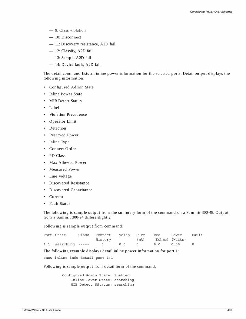
Configuring Power Over Ethernet
ExtremeWare 7
— 9: Class violation
— 10: Disconnect
— 11: Discovery resistance, A2D fail
— 12: Classify, A2D fail
— 13: Sample A2D fail
— 14: Device fault, A2D fail
The detail command lists all inline power information for the selected ports. Detail output displays the following information:
• Configured Admin State
• Inline Power State
• MIB Detect Status
• Label
• Violation Precedence
• Operator Limit
• Detection
• Reserved Power
• Inline Type
• Connect Order
• PD Class
• Max Allowed Power
• Measured Power
• Line Voltage
• Discovered Resistance
• Discovered Capacitance
• Current
• Fault Status
The following is sample output from the summary form of the command on a Summit 300-48. Output from a Summit 300-24 differs slightly.
Following is sample output from command:
Port State Class Connect Volts Curr Res Power FaultHistory (mA) (Kohms) (Watts)
1:1 searching ----- 0 0.0 0 0.0 0.00 0
The following example displays detail inline power information for port 1:
show inline info detail port 1:1
Following is sample output from detail form of the command:
Configured Admin State: EnabledInline Power State: searchingMIB Detect SStatus: searching
.3e User Guide 401

Power Over Ethernet
Lable: Violation Precedence: max-class-operator
Operator Limit: 15400 milliwattsDetection: auto
Reserved Power: 0 milliwattsInline Type: other
Connect Order: nonePD Class:
Max Allowed Power: 0.0 WMeasured Power: 0.0 WLine Voltage: 0.0 Volts
Discovered Resistance: 0.0K ohmsDiscovered Capacitance: 0 uF
Current: 0 mAFault Status: None
402 ExtremeWare 7.3e User Guide
Part 4
Appendixes

A Using ExtremeWare Vista
ExtremeWare 7
This chapter describes the following topics:
• ExtremeWare Vista Overview on page 405
• Accessing ExtremeWare Vista on page 406
• Navigating within ExtremeWare Vista on page 408
• Configuring an “e” Series Switch Using ExtremeWare Vista on page 409
• Reviewing ExtremeWare Vista Statistical Reports on page 431
• Locating Support Information on page 446
• Logging Out of ExtremeWare Vista on page 450
ExtremeWare Vista Overview
A standard device-management feature on the Summit “e” series of switches is ExtremeWare Vista. Using a web browser, ExtremeWare Vista allows you to access the switch over a TCP/IP network. ExtremeWare Vista provides a subset of the command-line interface (CLI) in a graphical format that allows you to configure the switch and review statistical reports. However because ExtremeWare Vista includes only a subset of the CLI, some commands for the switch are not available using ExtremeWare Vista. If a particular command is not represented in ExtremeWare Vista, you must use the CLI to achieve the desired result.
Before attempting to access ExtremeWare Vista, ensure that:
• You assign an IP address to a VLAN to access the switch. For more information on assigning an IP address, see “Configuring Switch IP Parameters” on page 43.
• You have a properly configured standard web browser that supports frames and JavaScript (such as Netscape Navigator 3.0 or above, or Microsoft Internet Explorer 3.0 or above).
Setting Up Your BrowserIn general, the default settings that come configured on your browser work well with ExtremeWare Vista. The following are recommended settings that you can use to improve the display features and functions of ExtremeWare Vista:
.3e User Guide 405
Using ExtremeWare Vista
• After downloading a newer version of the switch image, clear the browser disk and memory cache to see the updated menus. You must clear the cache while on the main ExtremeWare Vista Logon page, so that all underlying.GIF files are updated.
• Check for newer versions of stored pages. Every visit to the page should be selected as a cache setting.
If you are using Netscape Navigator, configure the cache option to check for changes “Every Time” you request a page.
If you are using Microsoft Internet Explorer, configure the Temporary Internet Files setting to check for newer versions of stored pages by selecting “Every visit to the page.”
• On older-browsers you might need to specify that images be auto-loaded.
• Use a high-resolution monitor to maximize the amount of information displayed in the content frame. The recommended resolution is 1024 x 768 pixels. You can also use 800 x 600 pixels.
• Turn off one or more of the browser toolbars to maximize the viewing space of the ExtremeWare Vista content screen.
• If you will be using ExtremeWare Vista to send an email to the Extreme Networks Technical Support department, configure the email settings in your browser.
• Configure the browser to use the following recommended fonts:
— Proportional font—Times New Roman
— Fixed-width font—Courier New
Accessing ExtremeWare Vista
After an IP address is assigned to the VLAN, you can access the default home page of the switch.
1 Enter the following command in your browser:
http://<ipaddress>
The home page for ExtremeWare Vista opens as shown in Figure 58.
406 ExtremeWare 7.3e User Guide
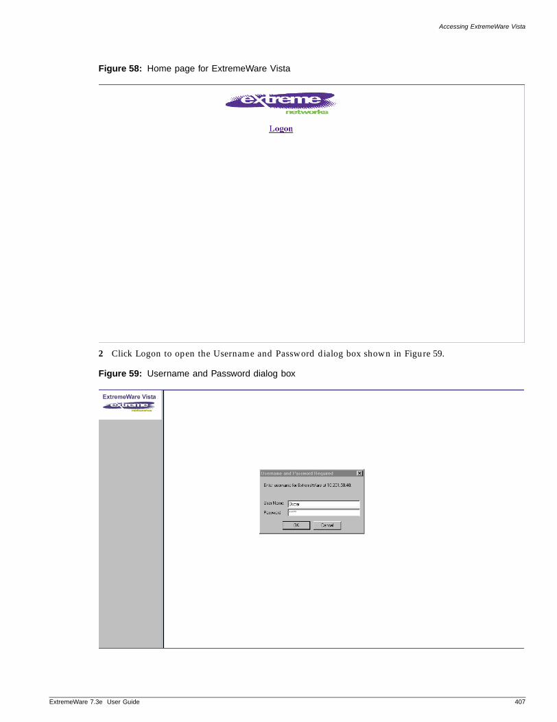
Accessing ExtremeWare Vista
ExtremeWare 7
Figure 58: Home page for ExtremeWare Vista
2 Click Logon to open the Username and Password dialog box shown in Figure 59.
Figure 59: Username and Password dialog box
.3e User Guide 407
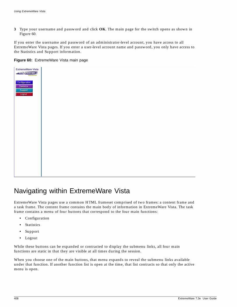
Using ExtremeWare Vista
3 Type your username and password and click OK. The main page for the switch opens as shown in Figure 60.
If you enter the username and password of an administrator-level account, you have access to all ExtremeWare Vista pages. If you enter a user-level account name and password, you only have access to the Statistics and Support information.
Figure 60: ExtremeWare Vista main page
Navigating within ExtremeWare Vista
ExtremeWare Vista pages use a common HTML frameset comprised of two frames: a content frame and a task frame. The content frame contains the main body of information in ExtremeWare Vista. The task frame contains a menu of four buttons that correspond to the four main functions:
• Configuration
• Statistics
• Support
• Logout
While these buttons can be expanded or contracted to display the submenu links, all four main functions are static in that they are visible at all times during the session.
When you choose one of the main buttons, that menu expands to reveal the submenu links available under that function. If another function list is open at the time, that list contracts so that only the active menu is open.
408 ExtremeWare 7.3e User Guide
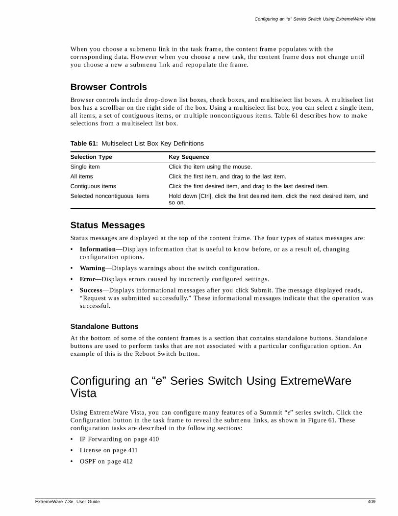
Configuring an “e” Series Switch Using ExtremeWare Vista
ExtremeWare 7
When you choose a submenu link in the task frame, the content frame populates with the corresponding data. However when you choose a new task, the content frame does not change until you choose a new a submenu link and repopulate the frame.
Browser ControlsBrowser controls include drop-down list boxes, check boxes, and multiselect list boxes. A multiselect list box has a scrollbar on the right side of the box. Using a multiselect list box, you can select a single item, all items, a set of contiguous items, or multiple noncontiguous items. Table 61 describes how to make selections from a multiselect list box.
Status MessagesStatus messages are displayed at the top of the content frame. The four types of status messages are:
• Information—Displays information that is useful to know before, or as a result of, changing configuration options.
• Warning—Displays warnings about the switch configuration.
• Error—Displays errors caused by incorrectly configured settings.
• Success—Displays informational messages after you click Submit. The message displayed reads, “Request was submitted successfully.” These informational messages indicate that the operation was successful.
Standalone Buttons
At the bottom of some of the content frames is a section that contains standalone buttons. Standalone buttons are used to perform tasks that are not associated with a particular configuration option. An example of this is the Reboot Switch button.
Configuring an “e” Series Switch Using ExtremeWare Vista
Using ExtremeWare Vista, you can configure many features of a Summit “e” series switch. Click the Configuration button in the task frame to reveal the submenu links, as shown in Figure 61. These configuration tasks are described in the following sections:
• IP Forwarding on page 410
• License on page 411
• OSPF on page 412
Table 61: Multiselect List Box Key Definitions
Selection Type Key Sequence
Single item Click the item using the mouse.
All items Click the first item, and drag to the last item.
Contiguous items Click the first desired item, and drag to the last desired item.
Selected noncontiguous items Hold down [Ctrl], click the first desired item, click the next desired item, and so on.
.3e User Guide 409
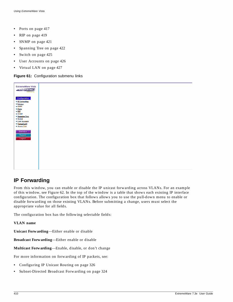
Using ExtremeWare Vista
• Ports on page 417
• RIP on page 419
• SNMP on page 421
• Spanning Tree on page 422
• Switch on page 425
• User Accounts on page 426
• Virtual LAN on page 427
Figure 61: Configuration submenu links
IP ForwardingFrom this window, you can enable or disable the IP unicast forwarding across VLANs. For an example of this window, see Figure 62. In the top of the window is a table that shows each existing IP interface configuration. The configuration box that follows allows you to use the pull-down menu to enable or disable forwarding on those existing VLANs. Before submitting a change, users must select the appropriate value for all fields.
The configuration box has the following selectable fields:
VLAN name
Unicast Forwarding—Either enable or disable
Broadcast Forwarding—Either enable or disable
Multicast Forwarding—Enable, disable, or don’t change
For more information on forwarding of IP packets, see:
• Configuring IP Unicast Routing on page 326
• Subnet-Directed Broadcast Forwarding on page 324
410 ExtremeWare 7.3e User Guide
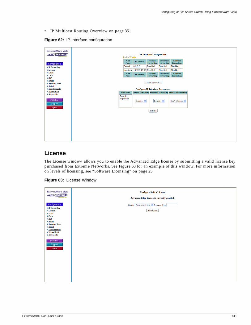
Configuring an “e” Series Switch Using ExtremeWare Vista
ExtremeWare 7
• IP Multicast Routing Overview on page 351
Figure 62: IP interface configuration
LicenseThe License window allows you to enable the Advanced Edge license by submitting a valid license key purchased from Extreme Networks. See Figure 63 for an example of this window. For more information on levels of licensing, see “Software Licensing” on page 25.
Figure 63: License Window
.3e User Guide 411
Using ExtremeWare Vista
OSPFThe OSPF configuration window allows you to perform a wide-range of OSPF configuration tasks. The window is divided into seven functional areas:
1 Configure global OSPF parameters including enabling or disabling of the exporting of RIP, static, and direct (interface) routes to OSPF
2 Create or delete an OSPF area
3 Configure a range of IP addresses in an OSPF area
4 Configure an OSPF area
5 Configure an IP interface for OSPF
6 Configure OSPF virtual link
7 Configure OSPF authentication
Configure Global OSPF Parameters
Use the global parameters to set up OSPF throughout the switch. See the top portion of Figure 64 for an example of the global parameters window.
NOTE
Before you can make global changes to OSPF, you must first disable OSPF Export Static and OSPF Export RIP.
From this portion of the window, you can:
• Enable or disable the exporting of RIP, static, and direct (interface) routes to OSPF. Be sure you disable exporting of static and RIP before setting other global OSPF parameters.
• Enable or disable the exporting of static, direct, and OSPF-learned routes into a RIP domain.
• Set the route type as external type 1 or external type 2.
• Set the cost metric for all RIP-learned, static, and direct routes injected into OSPF. If the cost metric is set to 0, the cost is inserted from the route.
• Set a tag value for use by special routing applications. Use 0 if you do not have specific requirements for using a tag. The tag value in this instance has no relationship with 802.1Q VLAN tagging.
• Set the OSPF router ID to a user-specified value or to automatic.
• Enable or disable OSPF.
412 ExtremeWare 7.3e User Guide
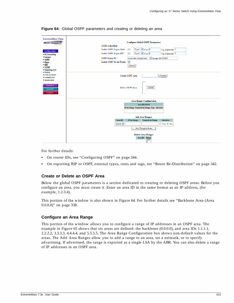
Configuring an “e” Series Switch Using ExtremeWare Vista
ExtremeWare 7
Figure 64: Global OSPF parameters and creating or deleting an area
For further details:
• On router IDs, see “Configuring OSPF” on page 344.
• On exporting RIP or OSPF, external types, costs and tags, see “Route Re-Distribution” on page 342.
Create or Delete an OSPF Area
Below the global OSPF parameters is a section dedicated to creating or deleting OSPF areas. Before you configure an area, you must create it. Enter an area ID in the same format as an IP address, (for example, 1.2.3.4).
This portion of the window is also shown in Figure 64. For further details see “Backbone Area (Area 0.0.0.0)” on page 338.
Configure an Area Range
This portion of the window allows you to configure a range of IP addresses in an OSPF area. The example in Figure 65 shows that six areas are defined: the backbone (0.0.0.0), and area IDs 1.1.1.1, 2.2.2.2, 3.3.3.3, 4.4.4.4, and 5.5.5.5. The Area Range Configuration box shows non-default values for the areas. The Add Area Ranges allow you to add a range to an area, set a netmask, or to specify advertising. If advertised, the range is exported as a single LSA by the ABR. You can also delete a range of IP addresses in an OSPF area.
.3e User Guide 413
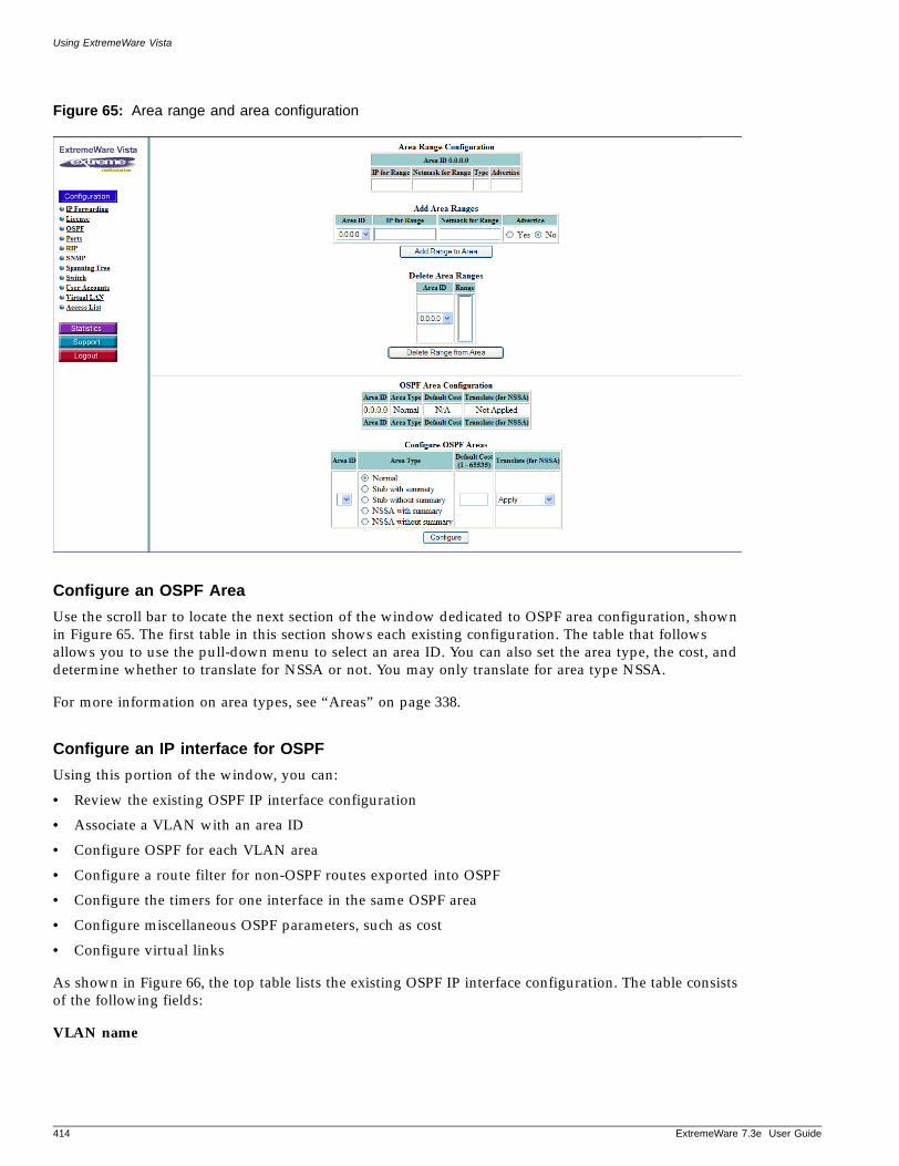
Using ExtremeWare Vista
Figure 65: Area range and area configuration
Configure an OSPF Area
Use the scroll bar to locate the next section of the window dedicated to OSPF area configuration, shown in Figure 65. The first table in this section shows each existing configuration. The table that follows allows you to use the pull-down menu to select an area ID. You can also set the area type, the cost, and determine whether to translate for NSSA or not. You may only translate for area type NSSA.
For more information on area types, see “Areas” on page 338.
Configure an IP interface for OSPF
Using this portion of the window, you can:
• Review the existing OSPF IP interface configuration
• Associate a VLAN with an area ID
• Configure OSPF for each VLAN area
• Configure a route filter for non-OSPF routes exported into OSPF
• Configure the timers for one interface in the same OSPF area
• Configure miscellaneous OSPF parameters, such as cost
• Configure virtual links
As shown in Figure 66, the top table lists the existing OSPF IP interface configuration. The table consists of the following fields:
VLAN name
414 ExtremeWare 7.3e User Guide
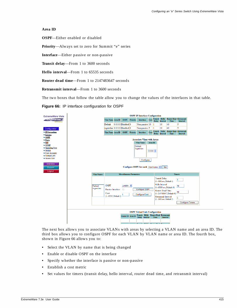
Configuring an “e” Series Switch Using ExtremeWare Vista
ExtremeWare 7
Area ID
OSPF—Either enabled or disabled
Priority—Always set to zero for Summit “e” series
Interface—Either passive or non-passive
Transit delay—From 1 to 3600 seconds
Hello interval—From 1 to 65535 seconds
Router dead time—From 1 to 2147483647 seconds
Retransmit interval—From 1 to 3600 seconds
The two boxes that follow the table allow you to change the values of the interfaces in that table.
Figure 66: IP interface configuration for OSPF
The next box allows you to associate VLANs with areas by selecting a VLAN name and an area ID. The third box allows you to configure OSPF for each VLAN by VLAN name or area ID. The fourth box, shown in Figure 66 allows you to:
• Select the VLAN by name that is being changed
• Enable or disable OSPF on the interface
• Specify whether the interface is passive or non-passive
• Establish a cost metric
• Set values for timers (transit delay, hello interval, router dead time, and retransmit interval)
.3e User Guide 415
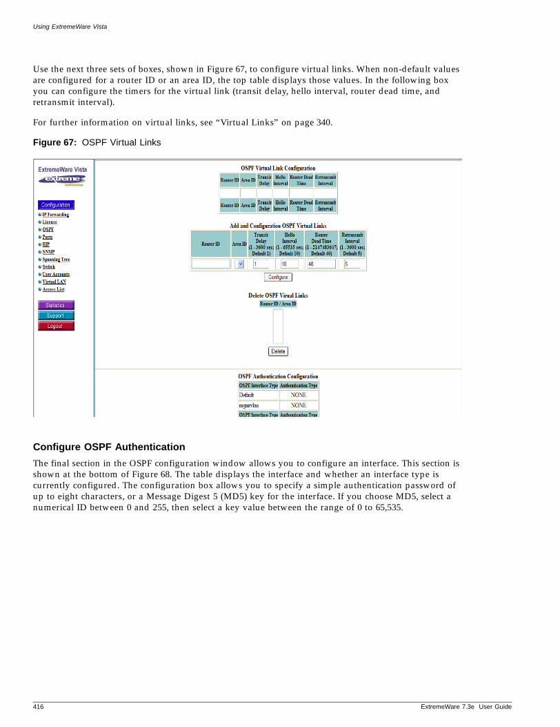
Using ExtremeWare Vista
Use the next three sets of boxes, shown in Figure 67, to configure virtual links. When non-default values are configured for a router ID or an area ID, the top table displays those values. In the following box you can configure the timers for the virtual link (transit delay, hello interval, router dead time, and retransmit interval).
For further information on virtual links, see “Virtual Links” on page 340.
Figure 67: OSPF Virtual Links
Configure OSPF Authentication
The final section in the OSPF configuration window allows you to configure an interface. This section is shown at the bottom of Figure 68. The table displays the interface and whether an interface type is currently configured. The configuration box allows you to specify a simple authentication password of up to eight characters, or a Message Digest 5 (MD5) key for the interface. If you choose MD5, select a numerical ID between 0 and 255, then select a key value between the range of 0 to 65,535.
416 ExtremeWare 7.3e User Guide
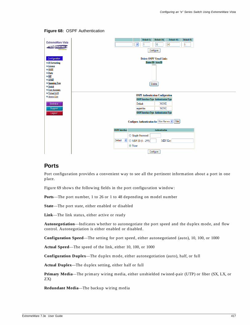
Configuring an “e” Series Switch Using ExtremeWare Vista
ExtremeWare 7
Figure 68: OSPF Authentication
PortsPort configuration provides a convenient way to see all the pertinent information about a port in one place.
Figure 69 shows the following fields in the port configuration window:
Ports—The port number, 1 to 26 or 1 to 48 depending on model number
State—The port state, either enabled or disabled
Link—The link status, either active or ready
Autonegotiation—Indicates whether to autonegotiate the port speed and the duplex mode, and flow control. Autonegotiation is either enabled or disabled.
Configuration Speed—The setting for port speed, either autonegotiated (auto), 10, 100, or 1000
Actual Speed—The speed of the link, either 10, 100, or 1000
Configuration Duplex—The duplex mode, either autonegotiation (auto), half, or full
Actual Duplex—The duplex setting, either half or full
Primary Media—The primary wiring media, either unshielded twisted-pair (UTP) or fiber (SX, LX, or ZX)
Redundant Media—The backup wiring media
.3e User Guide 417
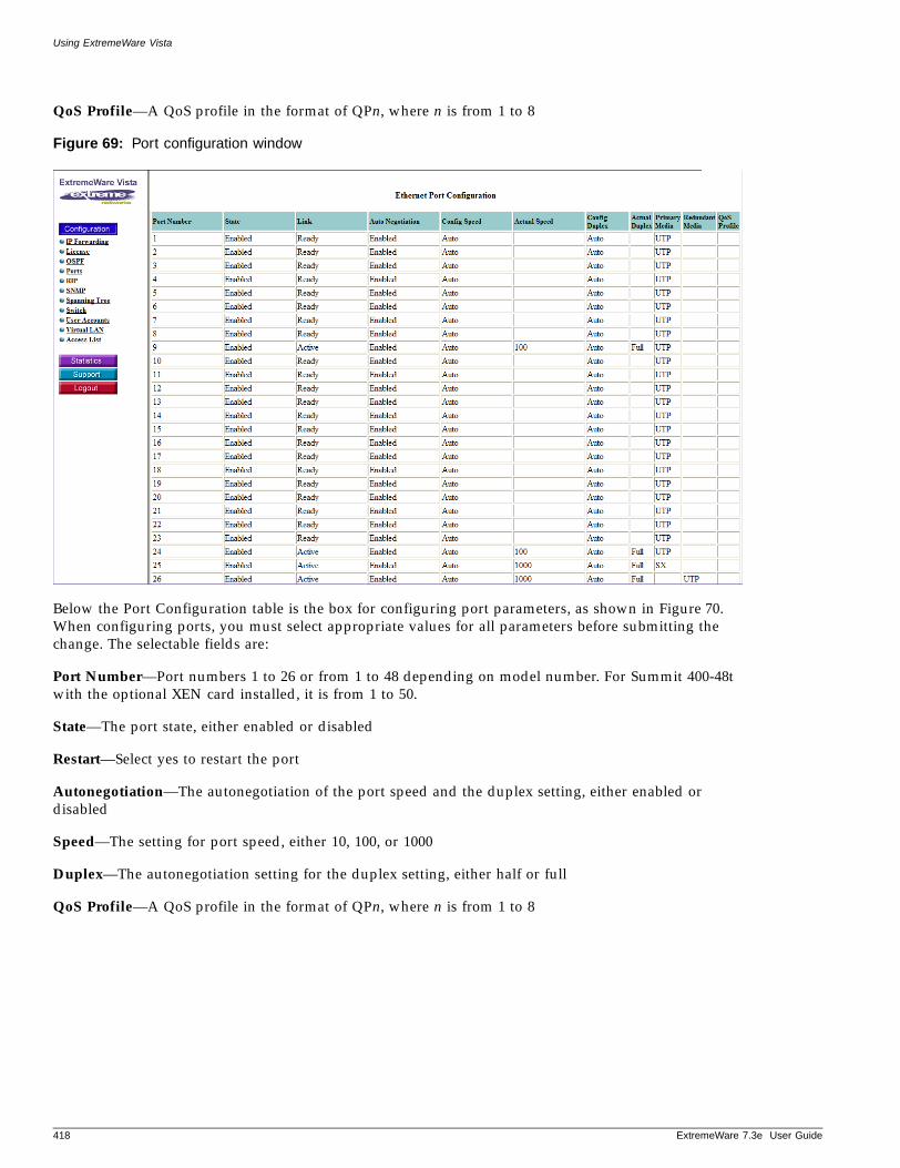
Using ExtremeWare Vista
QoS Profile—A QoS profile in the format of QPn, where n is from 1 to 8
Figure 69: Port configuration window
Below the Port Configuration table is the box for configuring port parameters, as shown in Figure 70. When configuring ports, you must select appropriate values for all parameters before submitting the change. The selectable fields are:
Port Number—Port numbers 1 to 26 or from 1 to 48 depending on model number. For Summit 400-48t with the optional XEN card installed, it is from 1 to 50.
State—The port state, either enabled or disabled
Restart—Select yes to restart the port
Autonegotiation—The autonegotiation of the port speed and the duplex setting, either enabled or disabled
Speed—The setting for port speed, either 10, 100, or 1000
Duplex—The autonegotiation setting for the duplex setting, either half or full
QoS Profile—A QoS profile in the format of QPn, where n is from 1 to 8
418 ExtremeWare 7.3e User Guide
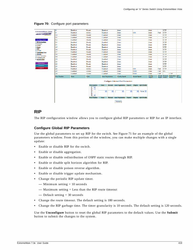
Configuring an “e” Series Switch Using ExtremeWare Vista
ExtremeWare 7
Figure 70: Configure port parameters
RIPThe RIP configuration window allows you to configure global RIP parameters or RIP for an IP interface.
Configure Global RIP Parameters
Use the global parameters to set up RIP for the switch. See Figure 71 for an example of the global parameters window. From this portion of the window, you can make multiple changes with a single update:
• Enable or disable RIP for the switch.
• Enable or disable aggregation.
• Enable or disable redistribution of OSPF static routes through RIP.
• Enable or disable split horizon algorithm for RIP.
• Enable or disable poison reverse algorithm.
• Enable or disable trigger update mechanism.
• Change the periodic RIP update timer.
— Minimum setting = 10 seconds
— Maximum setting = Less than the RIP route timeout
— Default setting = 30 seconds
• Change the route timeout. The default setting is 180 seconds.
• Change the RIP garbage time. The timer granularity is 10 seconds. The default setting is 120 seconds.
Use the Unconfigure button to reset the global RIP parameters to the default values. Use the Submit button to submit the changes to the system.
.3e User Guide 419
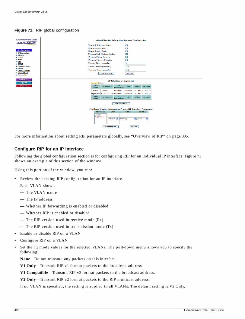
Using ExtremeWare Vista
Figure 71: RIP global configuration
For more information about setting RIP parameters globally, see “Overview of RIP” on page 335.
Configure RIP for an IP interface
Following the global configuration section is for configuring RIP for an individual IP interface. Figure 71 shows an example of this section of the window.
Using this portion of the window, you can:
• Review the existing RIP configuration for an IP interface.
Each VLAN shows:
— The VLAN name
— The IP address
— Whether IP forwarding is enabled or disabled
— Whether RIP is enabled or disabled
— The RIP version used in receive mode (Rx)
— The RIP version used in transmission mode (Tx)
• Enable or disable RIP on a VLAN
• Configure RIP on a VLAN
• Set the Tx mode values for the selected VLANs. The pull-down menu allows you to specify the following:
None—Do not transmit any packets on this interface.
V1 Only—Transmit RIP v1 format packets to the broadcast address.
V1 Compatible—Transmit RIP v2 format packets to the broadcast address.
V2 Only—Transmit RIP v2 format packets to the RIP multicast address.
If no VLAN is specified, the setting is applied to all VLANs. The default setting is V2 Only.
420 ExtremeWare 7.3e User Guide

Configuring an “e” Series Switch Using ExtremeWare Vista
ExtremeWare 7
• Set the Rx mode values for the selected VLANs. The pull-down menu allows you to specify the following:
None—Do not receive packets on this interface.
Any—Receive packets on this interface in any mode.
V1 Only—Receive RIP v1 format packets to the broadcast address.
V2 Only—Receive RIP v2 format packets to the RIP multicast address.
If no VLAN is specified, the setting is applied to all VLANs. The default setting is V2 Only.
• Use the Unconfigure button to reset the RIP configuration for the VLAN to the default values.
• Use the Submit button to submit the changes to the system.
SNMPThe SNMP window is divided into two sections. The top section allows you to enter system group information and authentication information for the community strings. The bottom section allows you to set the configuration associated with SNMP traps.
System Group Configuration
As shown in Figure 72, this portion of the SNMP window allows you to set:
Contact —A text field that enables you to enter the contact information of the person responsible for managing the switch.
Name—The system name is the name that you have assigned to this switch. The default name is the model name of the switch (for example, Summit 400-48t switch).
Location —The location of this switch.
.3e User Guide 421
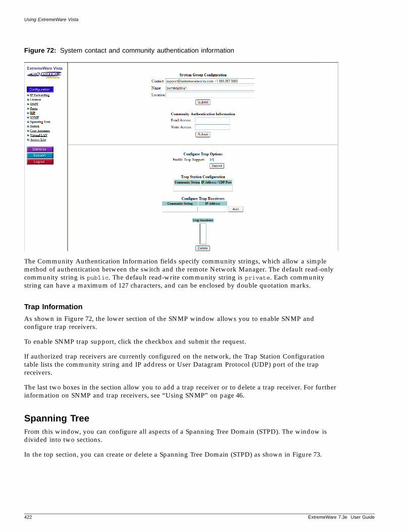
Using ExtremeWare Vista
Figure 72: System contact and community authentication information
The Community Authentication Information fields specify community strings, which allow a simple method of authentication between the switch and the remote Network Manager. The default read-only community string is public. The default read-write community string is private. Each community string can have a maximum of 127 characters, and can be enclosed by double quotation marks.
Trap Information
As shown in Figure 72, the lower section of the SNMP window allows you to enable SNMP and configure trap receivers.
To enable SNMP trap support, click the checkbox and submit the request.
If authorized trap receivers are currently configured on the network, the Trap Station Configuration table lists the community string and IP address or User Datagram Protocol (UDP) port of the trap receivers.
The last two boxes in the section allow you to add a trap receiver or to delete a trap receiver. For further information on SNMP and trap receivers, see “Using SNMP” on page 46.
Spanning TreeFrom this window, you can configure all aspects of a Spanning Tree Domain (STPD). The window is divided into two sections.
In the top section, you can create or delete a Spanning Tree Domain (STPD) as shown in Figure 73.
422 ExtremeWare 7.3e User Guide
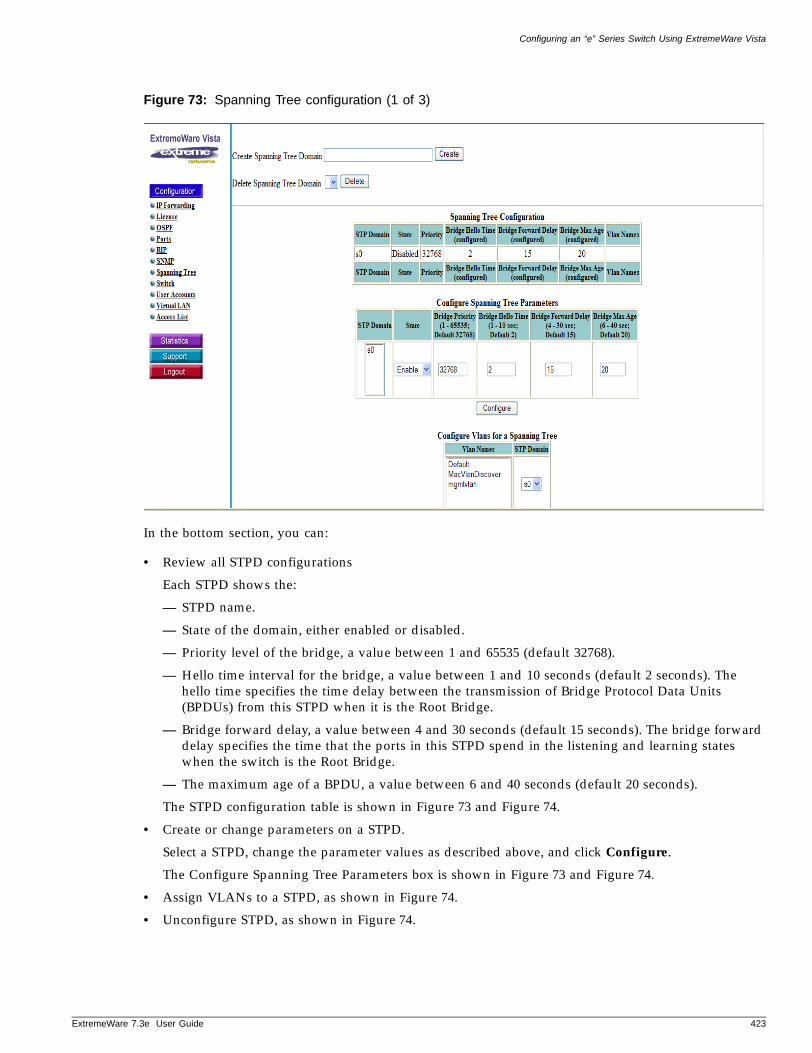
Configuring an “e” Series Switch Using ExtremeWare Vista
ExtremeWare 7
Figure 73: Spanning Tree configuration (1 of 3)
In the bottom section, you can:
• Review all STPD configurations
Each STPD shows the:
— STPD name.
— State of the domain, either enabled or disabled.
— Priority level of the bridge, a value between 1 and 65535 (default 32768).
— Hello time interval for the bridge, a value between 1 and 10 seconds (default 2 seconds). The hello time specifies the time delay between the transmission of Bridge Protocol Data Units (BPDUs) from this STPD when it is the Root Bridge.
— Bridge forward delay, a value between 4 and 30 seconds (default 15 seconds). The bridge forward delay specifies the time that the ports in this STPD spend in the listening and learning states when the switch is the Root Bridge.
— The maximum age of a BPDU, a value between 6 and 40 seconds (default 20 seconds).
The STPD configuration table is shown in Figure 73 and Figure 74.
• Create or change parameters on a STPD.
Select a STPD, change the parameter values as described above, and click Configure.
The Configure Spanning Tree Parameters box is shown in Figure 73 and Figure 74.
• Assign VLANs to a STPD, as shown in Figure 74.
• Unconfigure STPD, as shown in Figure 74.
.3e User Guide 423
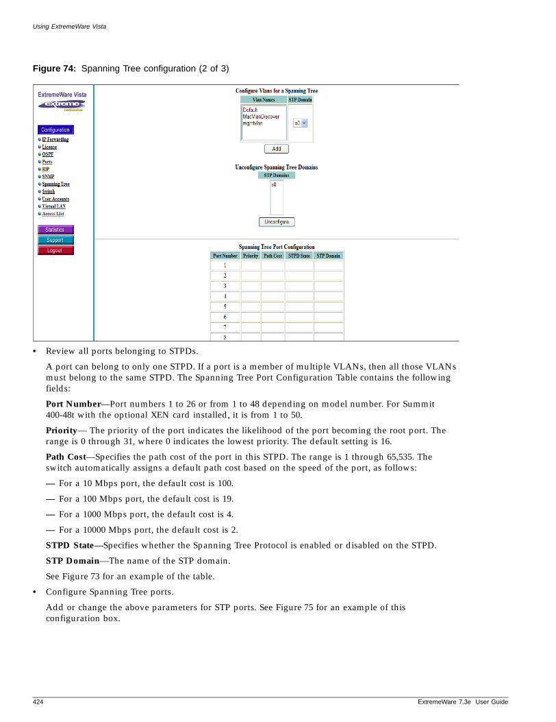
Using ExtremeWare Vista
Figure 74: Spanning Tree configuration (2 of 3)
• Review all ports belonging to STPDs.
A port can belong to only one STPD. If a port is a member of multiple VLANs, then all those VLANs must belong to the same STPD. The Spanning Tree Port Configuration Table contains the following fields:
Port Number—Port numbers 1 to 26 or from 1 to 48 depending on model number. For Summit 400-48t with the optional XEN card installed, it is from 1 to 50.
Priority— The priority of the port indicates the likelihood of the port becoming the root port. The range is 0 through 31, where 0 indicates the lowest priority. The default setting is 16.
Path Cost—Specifies the path cost of the port in this STPD. The range is 1 through 65,535. The switch automatically assigns a default path cost based on the speed of the port, as follows:
— For a 10 Mbps port, the default cost is 100.
— For a 100 Mbps port, the default cost is 19.
— For a 1000 Mbps port, the default cost is 4.
— For a 10000 Mbps port, the default cost is 2.
STPD State—Specifies whether the Spanning Tree Protocol is enabled or disabled on the STPD.
STP Domain—The name of the STP domain.
See Figure 73 for an example of the table.
• Configure Spanning Tree ports.
Add or change the above parameters for STP ports. See Figure 75 for an example of this configuration box.
424 ExtremeWare 7.3e User Guide
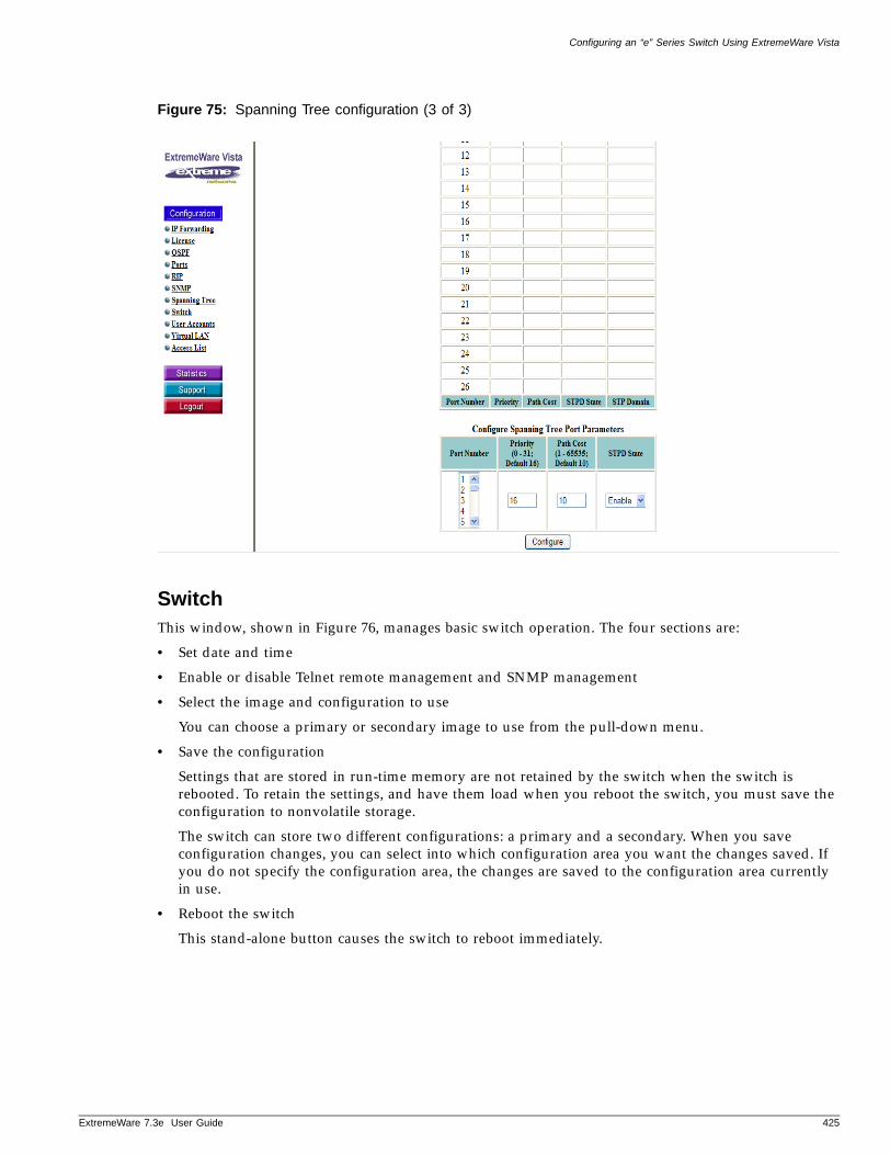
Configuring an “e” Series Switch Using ExtremeWare Vista
ExtremeWare 7
Figure 75: Spanning Tree configuration (3 of 3)
SwitchThis window, shown in Figure 76, manages basic switch operation. The four sections are:
• Set date and time
• Enable or disable Telnet remote management and SNMP management
• Select the image and configuration to use
You can choose a primary or secondary image to use from the pull-down menu.
• Save the configuration
Settings that are stored in run-time memory are not retained by the switch when the switch is rebooted. To retain the settings, and have them load when you reboot the switch, you must save the configuration to nonvolatile storage.
The switch can store two different configurations: a primary and a secondary. When you save configuration changes, you can select into which configuration area you want the changes saved. If you do not specify the configuration area, the changes are saved to the configuration area currently in use.
• Reboot the switch
This stand-alone button causes the switch to reboot immediately.
.3e User Guide 425
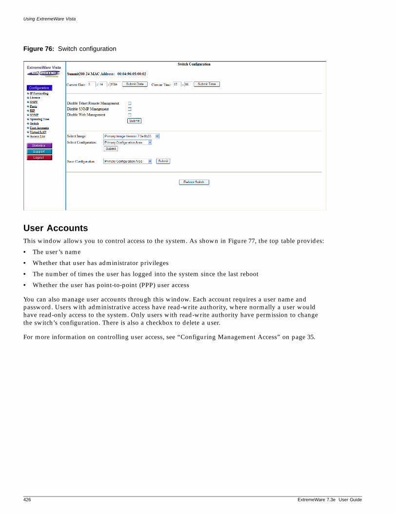
Using ExtremeWare Vista
Figure 76: Switch configuration
User AccountsThis window allows you to control access to the system. As shown in Figure 77, the top table provides:
• The user’s name
• Whether that user has administrator privileges
• The number of times the user has logged into the system since the last reboot
• Whether the user has point-to-point (PPP) user access
You can also manage user accounts through this window. Each account requires a user name and password. Users with administrative access have read-write authority, where normally a user would have read-only access to the system. Only users with read-write authority have permission to change the switch’s configuration. There is also a checkbox to delete a user.
For more information on controlling user access, see “Configuring Management Access” on page 35.
426 ExtremeWare 7.3e User Guide
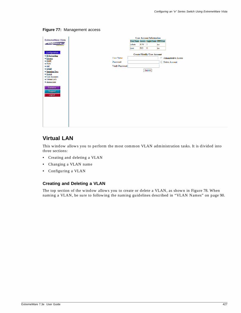
Configuring an “e” Series Switch Using ExtremeWare Vista
ExtremeWare 7
Figure 77: Management access
Virtual LANThis window allows you to perform the most common VLAN administration tasks. It is divided into three sections:
• Creating and deleting a VLAN
• Changing a VLAN name
• Configuring a VLAN
Creating and Deleting a VLAN
The top section of the window allows you to create or delete a VLAN, as shown in Figure 78. When naming a VLAN, be sure to following the naming guidelines described in “VLAN Names” on page 90.
.3e User Guide 427
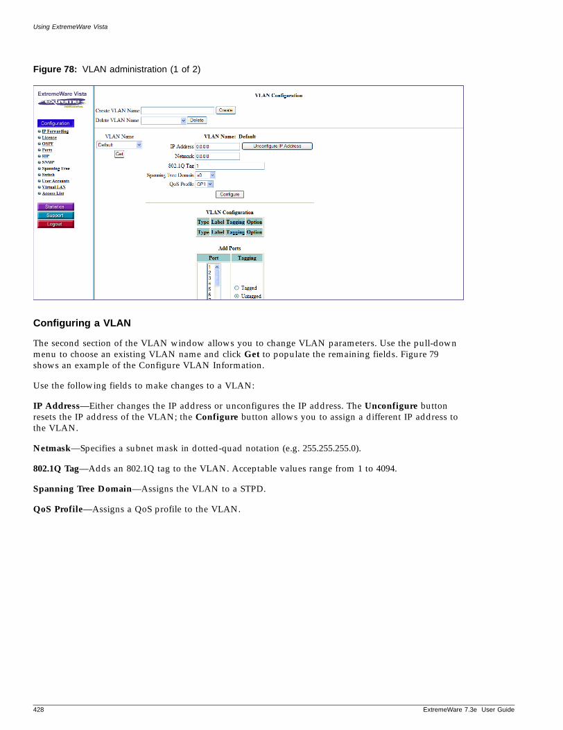
Using ExtremeWare Vista
Figure 78: VLAN administration (1 of 2)
Configuring a VLAN
The second section of the VLAN window allows you to change VLAN parameters. Use the pull-down menu to choose an existing VLAN name and click Get to populate the remaining fields. Figure 79 shows an example of the Configure VLAN Information.
Use the following fields to make changes to a VLAN:
IP Address—Either changes the IP address or unconfigures the IP address. The Unconfigure button resets the IP address of the VLAN; the Configure button allows you to assign a different IP address to the VLAN.
Netmask—Specifies a subnet mask in dotted-quad notation (e.g. 255.255.255.0).
802.1Q Tag—Adds an 802.1Q tag to the VLAN. Acceptable values range from 1 to 4094.
Spanning Tree Domain—Assigns the VLAN to a STPD.
QoS Profile—Assigns a QoS profile to the VLAN.
428 ExtremeWare 7.3e User Guide
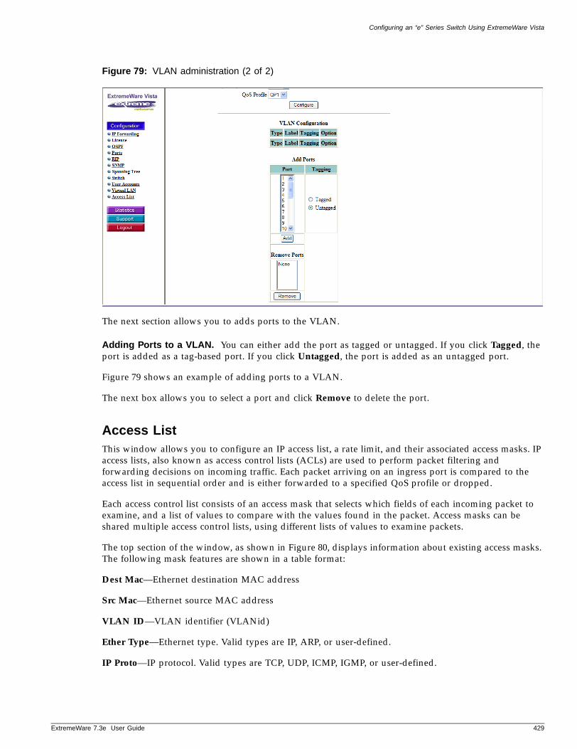
Configuring an “e” Series Switch Using ExtremeWare Vista
ExtremeWare 7
Figure 79: VLAN administration (2 of 2)
The next section allows you to adds ports to the VLAN.
Adding Ports to a VLAN. You can either add the port as tagged or untagged. If you click Tagged, the port is added as a tag-based port. If you click Untagged, the port is added as an untagged port.
Figure 79 shows an example of adding ports to a VLAN.
The next box allows you to select a port and click Remove to delete the port.
Access ListThis window allows you to configure an IP access list, a rate limit, and their associated access masks. IP access lists, also known as access control lists (ACLs) are used to perform packet filtering and forwarding decisions on incoming traffic. Each packet arriving on an ingress port is compared to the access list in sequential order and is either forwarded to a specified QoS profile or dropped.
Each access control list consists of an access mask that selects which fields of each incoming packet to examine, and a list of values to compare with the values found in the packet. Access masks can be shared multiple access control lists, using different lists of values to examine packets.
The top section of the window, as shown in Figure 80, displays information about existing access masks. The following mask features are shown in a table format:
Dest Mac—Ethernet destination MAC address
Src Mac—Ethernet source MAC address
VLAN ID—VLAN identifier (VLANid)
Ether Type—Ethernet type. Valid types are IP, ARP, or user-defined.
IP Proto—IP protocol. Valid types are TCP, UDP, ICMP, IGMP, or user-defined.
.3e User Guide 429
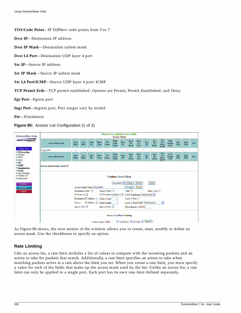
Using ExtremeWare Vista
TOS/Code Point—IP DiffServ code points from 0 to 7
Dest IP—Destination IP address
Dest IP Mask—Destination subnet mask
Dest L4 Port—Destination UDP layer 4 port
Src IP—Source IP address
Src IP Mask—Source IP subnet mask
Src L4 Port/ICMP—Source UDP layer 4 port/ICMP
TCP Permit Estb—TCP permit established. Options are Permit, Permit Established, and Deny.
Egr Port—Egress port
Ingr Port—Ingress port. Port ranges vary by model.
Pre—Precedence
Figure 80: Access List Configuration (1 of 2)
As Figure 80 shows, the next section of the window allows you to create, reset, modify or delete an access mask. Use the checkboxes to specify an option.
Rate Limiting
Like an access list, a rate limit includes a list of values to compare with the incoming packets and an action to take for packets that match. Additionally, a rate limit specifies an action to take when matching packets arrive at a rate above the limit you set. When you create a rate limit, you must specify a value for each of the fields that make up the access mask used by the list. Unlike an access list, a rate limit can only be applied to a single port. Each port has its own rate limit defined separately.
430 ExtremeWare 7.3e User Guide
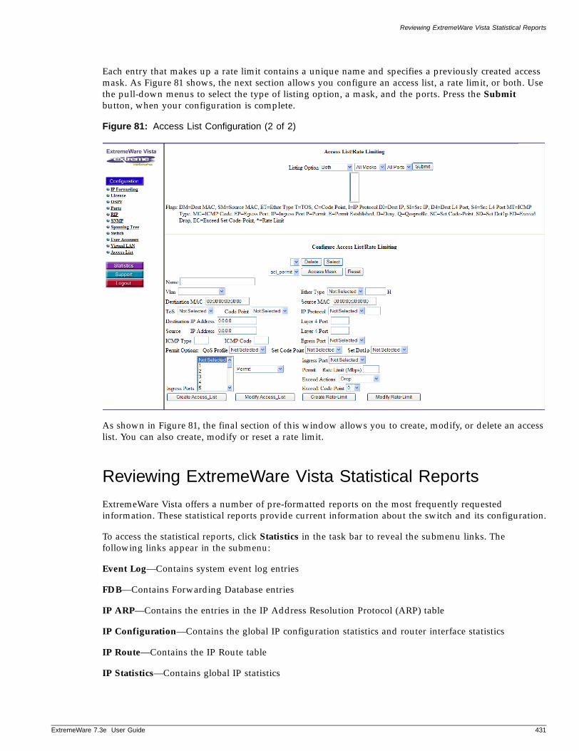
Reviewing ExtremeWare Vista Statistical Reports
ExtremeWare 7
Each entry that makes up a rate limit contains a unique name and specifies a previously created access mask. As Figure 81 shows, the next section allows you configure an access list, a rate limit, or both. Use the pull-down menus to select the type of listing option, a mask, and the ports. Press the Submit button, when your configuration is complete.
Figure 81: Access List Configuration (2 of 2)
As shown in Figure 81, the final section of this window allows you to create, modify, or delete an access list. You can also create, modify or reset a rate limit.
Reviewing ExtremeWare Vista Statistical Reports
ExtremeWare Vista offers a number of pre-formatted reports on the most frequently requested information. These statistical reports provide current information about the switch and its configuration.
To access the statistical reports, click Statistics in the task bar to reveal the submenu links. The following links appear in the submenu:
Event Log—Contains system event log entries
FDB—Contains Forwarding Database entries
IP ARP—Contains the entries in the IP Address Resolution Protocol (ARP) table
IP Configuration—Contains the global IP configuration statistics and router interface statistics
IP Route—Contains the IP Route table
IP Statistics—Contains global IP statistics
.3e User Guide 431
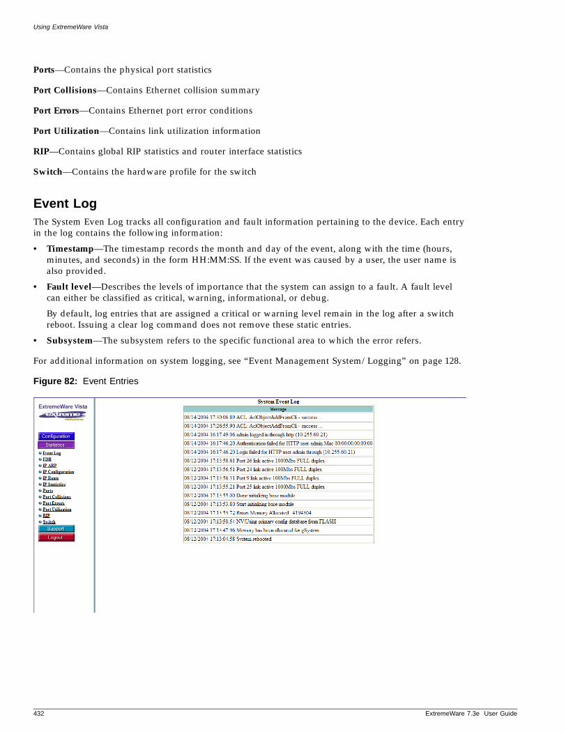
Using ExtremeWare Vista
Ports—Contains the physical port statistics
Port Collisions—Contains Ethernet collision summary
Port Errors—Contains Ethernet port error conditions
Port Utilization—Contains link utilization information
RIP—Contains global RIP statistics and router interface statistics
Switch—Contains the hardware profile for the switch
Event LogThe System Even Log tracks all configuration and fault information pertaining to the device. Each entry in the log contains the following information:
• Timestamp—The timestamp records the month and day of the event, along with the time (hours, minutes, and seconds) in the form HH:MM:SS. If the event was caused by a user, the user name is also provided.
• Fault level—Describes the levels of importance that the system can assign to a fault. A fault level can either be classified as critical, warning, informational, or debug.
By default, log entries that are assigned a critical or warning level remain in the log after a switch reboot. Issuing a clear log command does not remove these static entries.
• Subsystem—The subsystem refers to the specific functional area to which the error refers.
For additional information on system logging, see “Event Management System/Logging” on page 128.
Figure 82: Event Entries
432 ExtremeWare 7.3e User Guide
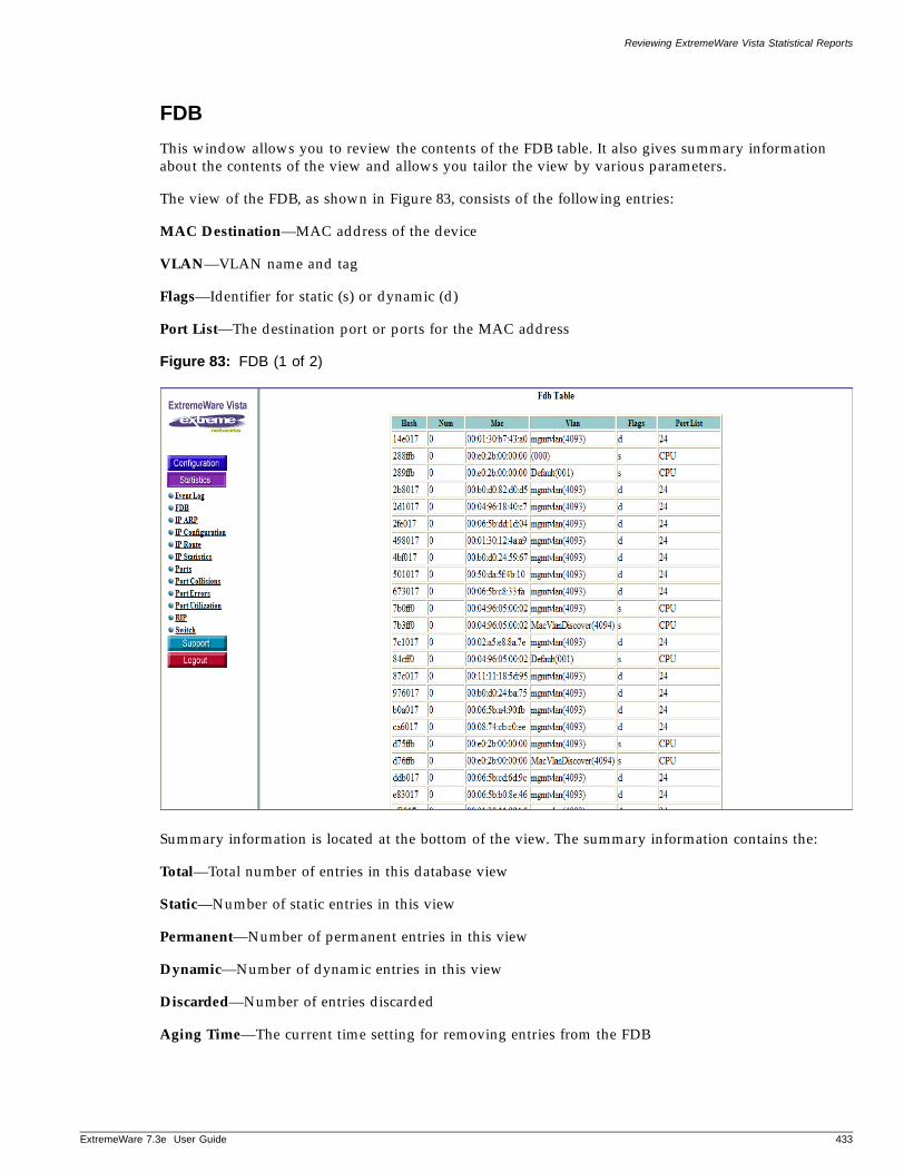
Reviewing ExtremeWare Vista Statistical Reports
ExtremeWare 7
FDB
This window allows you to review the contents of the FDB table. It also gives summary information about the contents of the view and allows you tailor the view by various parameters.
The view of the FDB, as shown in Figure 83, consists of the following entries:
MAC Destination—MAC address of the device
VLAN—VLAN name and tag
Flags—Identifier for static (s) or dynamic (d)
Port List—The destination port or ports for the MAC address
Figure 83: FDB (1 of 2)
Summary information is located at the bottom of the view. The summary information contains the:
Total—Total number of entries in this database view
Static—Number of static entries in this view
Permanent—Number of permanent entries in this view
Dynamic—Number of dynamic entries in this view
Discarded—Number of entries discarded
Aging Time—The current time setting for removing entries from the FDB
.3e User Guide 433
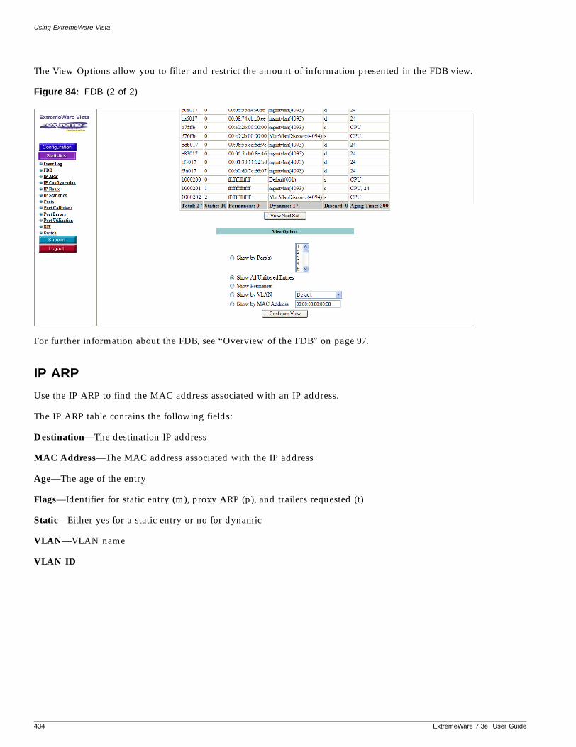
Using ExtremeWare Vista
The View Options allow you to filter and restrict the amount of information presented in the FDB view.
Figure 84: FDB (2 of 2)
For further information about the FDB, see “Overview of the FDB” on page 97.
IP ARP
Use the IP ARP to find the MAC address associated with an IP address.
The IP ARP table contains the following fields:
Destination—The destination IP address
MAC Address—The MAC address associated with the IP address
Age—The age of the entry
Flags—Identifier for static entry (m), proxy ARP (p), and trailers requested (t)
Static—Either yes for a static entry or no for dynamic
VLAN—VLAN name
VLAN ID
434 ExtremeWare 7.3e User Guide
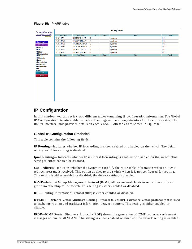
Reviewing ExtremeWare Vista Statistical Reports
ExtremeWare 7
Figure 85: IP ARP table
IP ConfigurationIn this window you can review two different tables containing IP configuration information. The Global IP Configuration Statistics table provides IP settings and summary statistics for the entire switch. The Router Interface table provides details on each VLAN. Both tables are shown in Figure 86.
Global IP Configuration Statistics
This table contains the following fields:
IP Routing—Indicates whether IP forwarding is either enabled or disabled on the switch. The default setting for IP forwarding is disabled.
Ipmc Routing— Indicates whether IP multicast forwarding is enabled or disabled on the switch. This setting is either enabled or disabled.
Use Redirects—Indicates whether the switch can modify the route table information when an ICMP redirect message is received. This option applies to the switch when it is not configured for routing. This setting is either enabled or disabled; the default setting is disabled.
IGMP—Internet Group Management Protocol (IGMP) allows network hosts to report the multicast group membership to the switch. This setting is either enabled or disabled.
RIP—Routing Information Protocol (RIP) is either enabled or disabled.
DVMRP—Distance Vector Multicast Routing Protocol (DVMRP), a distance vector protocol that is used to exchange routing and multicast information between routers. This setting is either enabled or disabled.
IRDP—ICMP Router Discovery Protocol (IRDP) shows the generation of ICMP router advertisement messages on one or all VLANs. The setting is either enabled or disabled; the default setting is enabled.
.3e User Guide 435
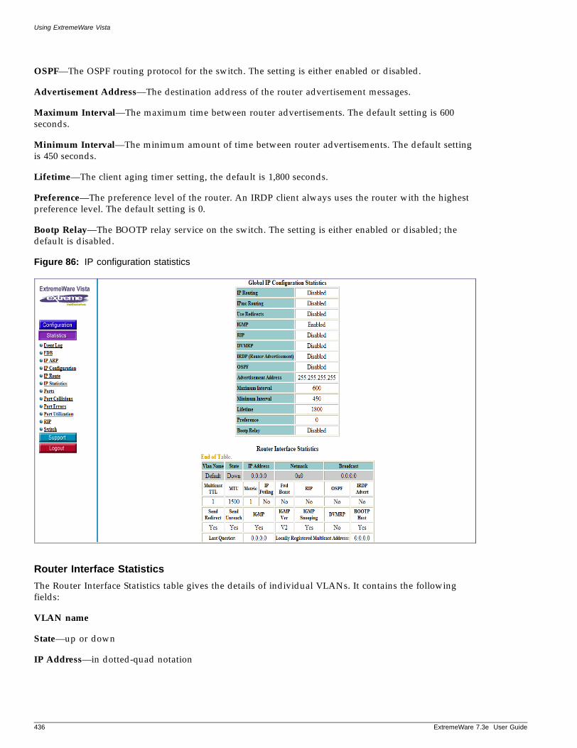
Using ExtremeWare Vista
OSPF—The OSPF routing protocol for the switch. The setting is either enabled or disabled.
Advertisement Address—The destination address of the router advertisement messages.
Maximum Interval—The maximum time between router advertisements. The default setting is 600 seconds.
Minimum Interval—The minimum amount of time between router advertisements. The default setting is 450 seconds.
Lifetime—The client aging timer setting, the default is 1,800 seconds.
Preference—The preference level of the router. An IRDP client always uses the router with the highest preference level. The default setting is 0.
Bootp Relay—The BOOTP relay service on the switch. The setting is either enabled or disabled; the default is disabled.
Figure 86: IP configuration statistics
Router Interface Statistics
The Router Interface Statistics table gives the details of individual VLANs. It contains the following fields:
VLAN name
State—up or down
IP Address—in dotted-quad notation
436 ExtremeWare 7.3e User Guide
Reviewing ExtremeWare Vista Statistical Reports
ExtremeWare 7
Netmask
Broadcast—The broadcast address in dotted-quad notation
Multicast TTL—The multicast time-to-live
MTU—Maximum Transmission Unit (MTU) size
Metric—The hop count to the destination address
IP Forwarding—IP forwarding on this interface is enabled (yes) or disabled (no)
Fwd Bcast—The hardware forwarding of subnet-directed broadcast IP packets is enabled (yes) or disabled (no)
RIP—RIP is enabled (yes) or disabled (no) on this interface
OSPF—OSPF is enabled (yes) or disabled (no) on this interface
IDRP—IDRP is enabled (yes) or disabled (no) on this interface
Send Redirect—Allows or disallows the interface to modify the route table information when an ICMP redirect message is received
Send Unreach—Allows or disallows the interface to generate an ICMP port unreachable messages (type 3, code 3) when a TPC or UDP request is made to the switch, and no application is waiting for the request, or access policy denies the request.
IGMP—IGMP is enabled (yes) or disabled (no) on this interface
IGMP Ver—The version of IGMP running on the interface
IGMP Snooping— IGMP Snooping is enabled (yes) or disabled (no)
DVMRP—Distance Vector Multicast Routing Protocol (DVMRP), a distance vector protocol that is used to exchange routing and multicast information between routers. This setting is either enabled (yes) or disabled (no).
BOOTP Host—Indicates whether BOOTP is enabled on this VLAN or not
Last Querier—The address of the querier
Locally Registered Multicast Address
Learned Multicast Address
IP RouteThis window contains the statistics for the IP routing table. The switch exchanges routing information with other routers and switches on the network using either the RIP or the OSPF protocol. The switch dynamically builds and maintains the routing table, and determines the best path for each of its routes.
The IP route table contains the following fields:
Destination—The destination address
Gateway—The gateway address
.3e User Guide 437
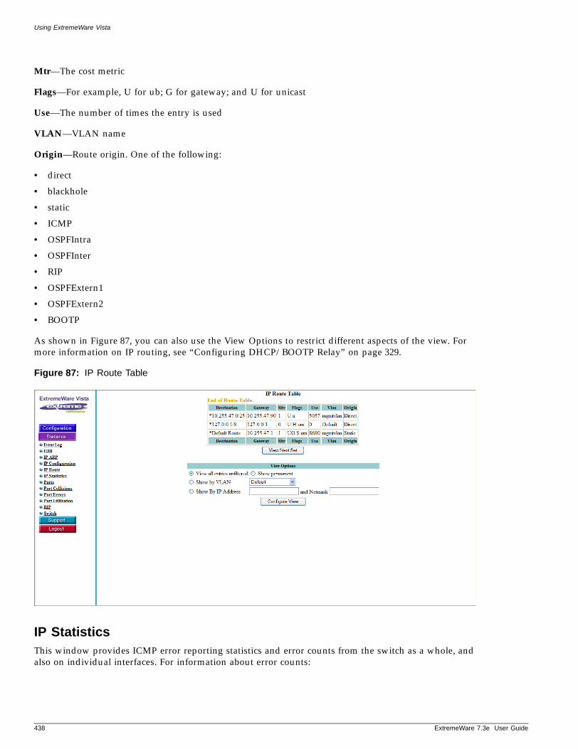
Using ExtremeWare Vista
Mtr—The cost metric
Flags—For example, U for ub; G for gateway; and U for unicast
Use—The number of times the entry is used
VLAN—VLAN name
Origin—Route origin. One of the following:
• direct
• blackhole
• static
• ICMP
• OSPFIntra
• OSPFInter
• RIP
• OSPFExtern1
• OSPFExtern2
• BOOTP
As shown in Figure 87, you can also use the View Options to restrict different aspects of the view. For more information on IP routing, see “Configuring DHCP/BOOTP Relay” on page 329.
Figure 87: IP Route Table
IP StatisticsThis window provides ICMP error reporting statistics and error counts from the switch as a whole, and also on individual interfaces. For information about error counts:
438 ExtremeWare 7.3e User Guide
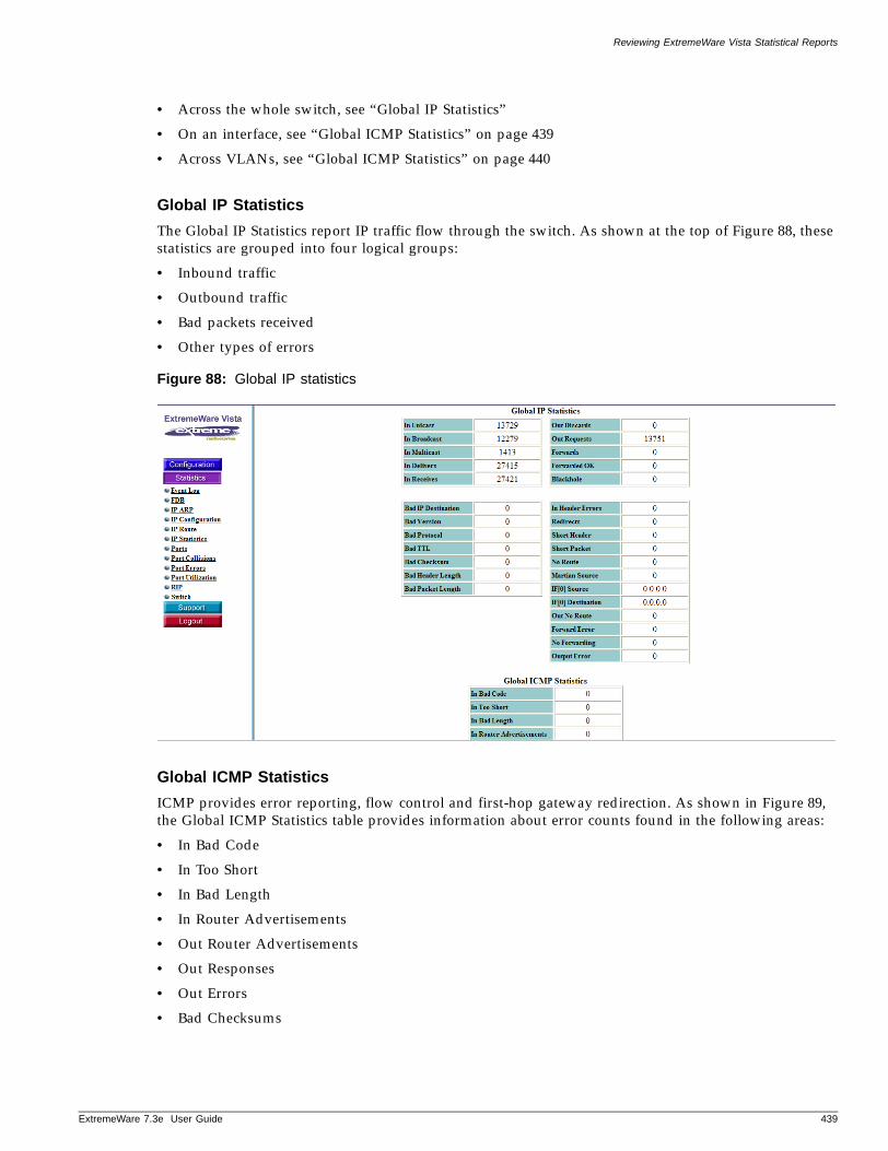
Reviewing ExtremeWare Vista Statistical Reports
ExtremeWare 7
• Across the whole switch, see “Global IP Statistics”
• On an interface, see “Global ICMP Statistics” on page 439
• Across VLANs, see “Global ICMP Statistics” on page 440
Global IP Statistics
The Global IP Statistics report IP traffic flow through the switch. As shown at the top of Figure 88, these statistics are grouped into four logical groups:
• Inbound traffic
• Outbound traffic
• Bad packets received
• Other types of errors
Figure 88: Global IP statistics
Global ICMP Statistics
ICMP provides error reporting, flow control and first-hop gateway redirection. As shown in Figure 89, the Global ICMP Statistics table provides information about error counts found in the following areas:
• In Bad Code
• In Too Short
• In Bad Length
• In Router Advertisements
• Out Router Advertisements
• Out Responses
• Out Errors
• Bad Checksums
.3e User Guide 439
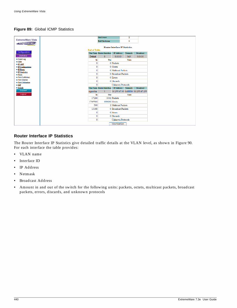
Using ExtremeWare Vista
Figure 89: Global ICMP Statistics
Router Interface IP Statistics
The Router Interface IP Statistics give detailed traffic details at the VLAN level, as shown in Figure 90. For each interface the table provides:
• VLAN name
• Interface ID
• IP Address
• Netmask
• Broadcast Address
• Amount in and out of the switch for the following units: packets, octets, multicast packets, broadcast packets, errors, discards, and unknown protocols
440 ExtremeWare 7.3e User Guide
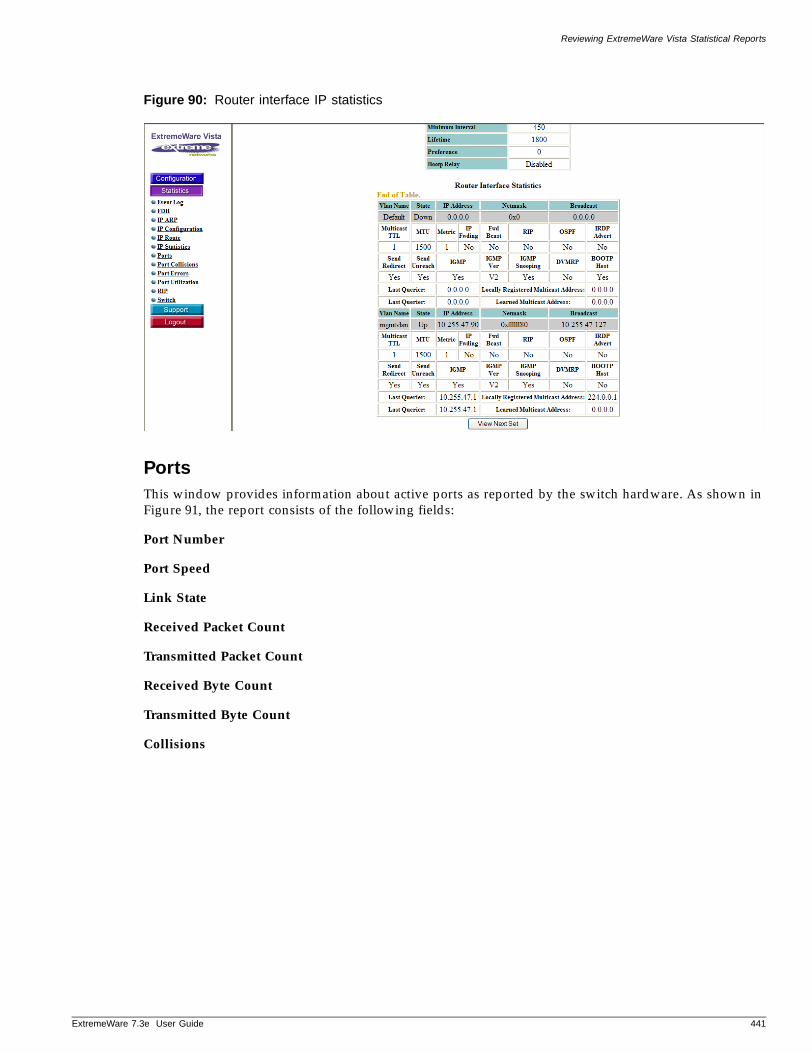
Reviewing ExtremeWare Vista Statistical Reports
ExtremeWare 7
Figure 90: Router interface IP statistics
PortsThis window provides information about active ports as reported by the switch hardware. As shown in Figure 91, the report consists of the following fields:
Port Number
Port Speed
Link State
Received Packet Count
Transmitted Packet Count
Received Byte Count
Transmitted Byte Count
Collisions
.3e User Guide 441
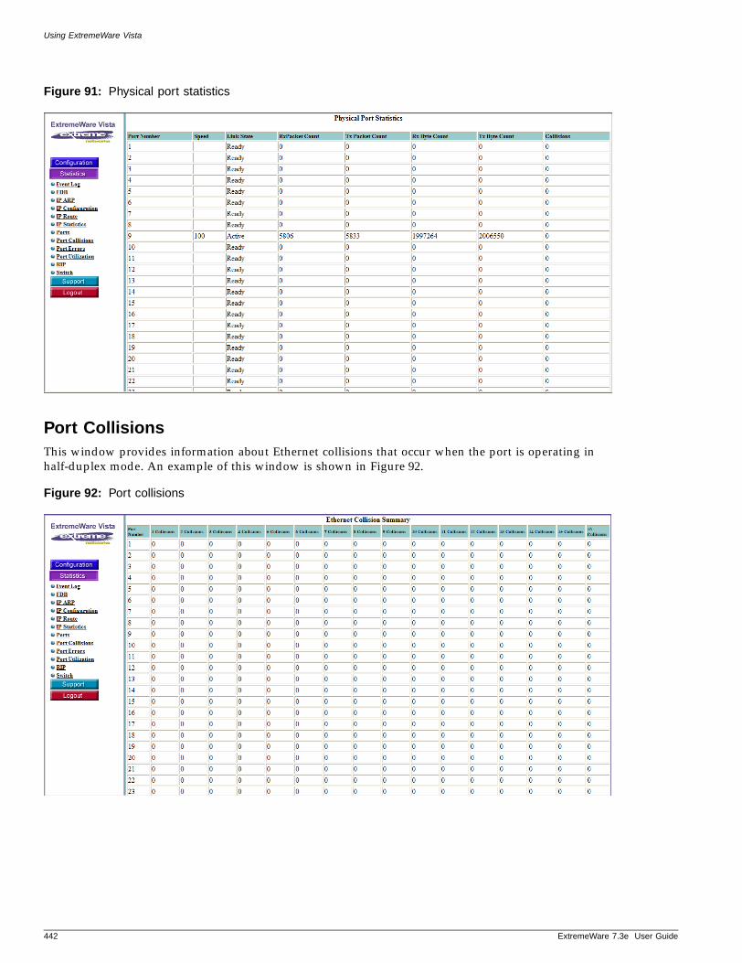
Using ExtremeWare Vista
Figure 91: Physical port statistics
Port CollisionsThis window provides information about Ethernet collisions that occur when the port is operating in half-duplex mode. An example of this window is shown in Figure 92.
Figure 92: Port collisions
442 ExtremeWare 7.3e User Guide
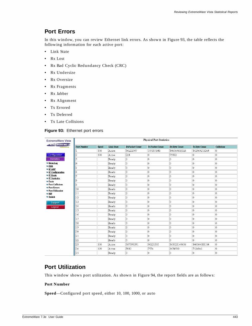
Reviewing ExtremeWare Vista Statistical Reports
ExtremeWare 7
Port ErrorsIn this window, you can review Ethernet link errors. As shown in Figure 93, the table reflects the following information for each active port:
• Link State
• Rx Lost
• Rx Bad Cyclic Redundancy Check (CRC)
• Rx Undersize
• Rx Oversize
• Rx Fragments
• Rx Jabber
• Rx Alignment
• Tx Errored
• Tx Deferred
• Tx Late Collisions
Figure 93: Ethernet port errors
Port UtilizationThis window shows port utilization. As shown in Figure 94, the report fields are as follows:
Port Number
Speed—Configured port speed, either 10, 100, 1000, or auto
.3e User Guide 443
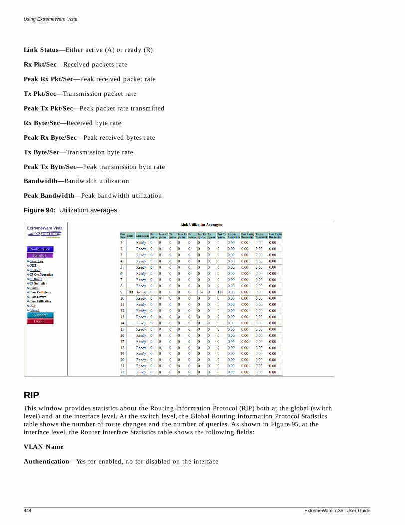
Using ExtremeWare Vista
Link Status—Either active (A) or ready (R)
Rx Pkt/Sec—Received packets rate
Peak Rx Pkt/Sec—Peak received packet rate
Tx Pkt/Sec—Transmission packet rate
Peak Tx Pkt/Sec—Peak packet rate transmitted
Rx Byte/Sec—Received byte rate
Peak Rx Byte/Sec—Peak received bytes rate
Tx Byte/Sec—Transmission byte rate
Peak Tx Byte/Sec—Peak transmission byte rate
Bandwidth—Bandwidth utilization
Peak Bandwidth—Peak bandwidth utilization
Figure 94: Utilization averages
RIPThis window provides statistics about the Routing Information Protocol (RIP) both at the global (switch level) and at the interface level. At the switch level, the Global Routing Information Protocol Statistics table shows the number of route changes and the number of queries. As shown in Figure 95, at the interface level, the Router Interface Statistics table shows the following fields:
VLAN Name
Authentication—Yes for enabled, no for disabled on the interface
444 ExtremeWare 7.3e User Guide
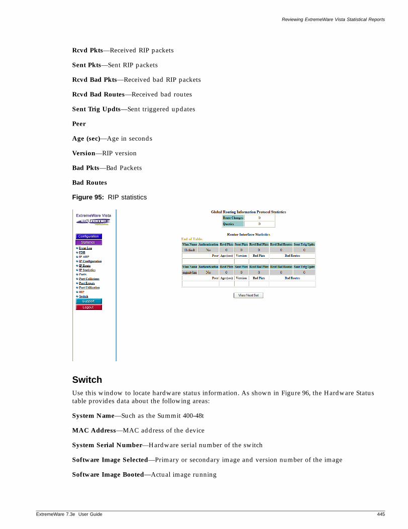
Reviewing ExtremeWare Vista Statistical Reports
ExtremeWare 7
Rcvd Pkts—Received RIP packets
Sent Pkts—Sent RIP packets
Rcvd Bad Pkts—Received bad RIP packets
Rcvd Bad Routes—Received bad routes
Sent Trig Updts—Sent triggered updates
Peer
Age (sec)—Age in seconds
Version—RIP version
Bad Pkts—Bad Packets
Bad Routes
Figure 95: RIP statistics
SwitchUse this window to locate hardware status information. As shown in Figure 96, the Hardware Status table provides data about the following areas:
System Name—Such as the Summit 400-48t
MAC Address—MAC address of the device
System Serial Number—Hardware serial number of the switch
Software Image Selected—Primary or secondary image and version number of the image
Software Image Booted—Actual image running
.3e User Guide 445
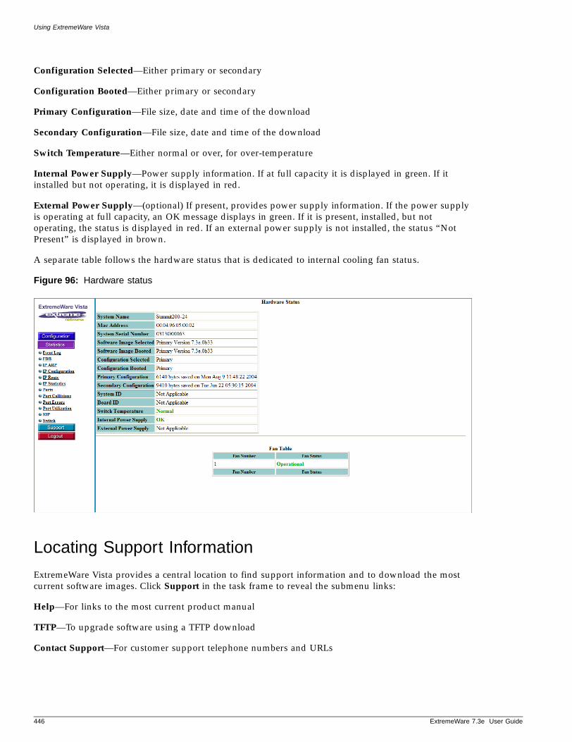
Using ExtremeWare Vista
Configuration Selected—Either primary or secondary
Configuration Booted—Either primary or secondary
Primary Configuration—File size, date and time of the download
Secondary Configuration—File size, date and time of the download
Switch Temperature—Either normal or over, for over-temperature
Internal Power Supply—Power supply information. If at full capacity it is displayed in green. If it installed but not operating, it is displayed in red.
External Power Supply—(optional) If present, provides power supply information. If the power supply is operating at full capacity, an OK message displays in green. If it is present, installed, but not operating, the status is displayed in red. If an external power supply is not installed, the status “Not Present” is displayed in brown.
A separate table follows the hardware status that is dedicated to internal cooling fan status.
Figure 96: Hardware status
Locating Support Information
ExtremeWare Vista provides a central location to find support information and to download the most current software images. Click Support in the task frame to reveal the submenu links:
Help—For links to the most current product manual
TFTP—To upgrade software using a TFTP download
Contact Support—For customer support telephone numbers and URLs
446 ExtremeWare 7.3e User Guide
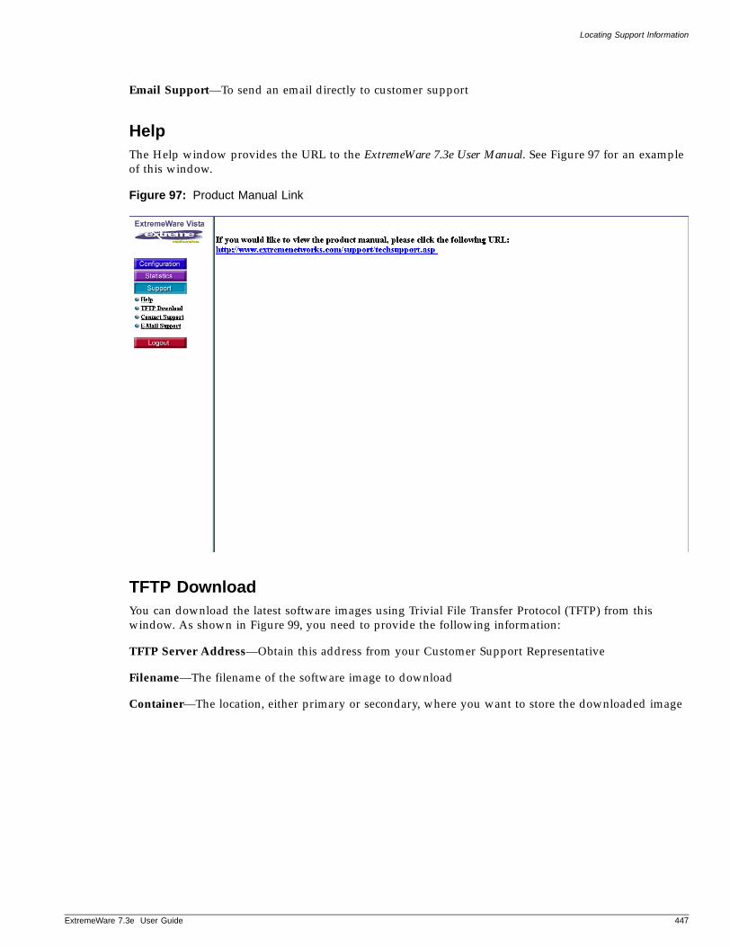
Locating Support Information
ExtremeWare 7
Email Support—To send an email directly to customer support
HelpThe Help window provides the URL to the ExtremeWare 7.3e User Manual. See Figure 97 for an example of this window.
Figure 97: Product Manual Link
TFTP DownloadYou can download the latest software images using Trivial File Transfer Protocol (TFTP) from this window. As shown in Figure 99, you need to provide the following information:
TFTP Server Address—Obtain this address from your Customer Support Representative
Filename—The filename of the software image to download
Container—The location, either primary or secondary, where you want to store the downloaded image
.3e User Guide 447
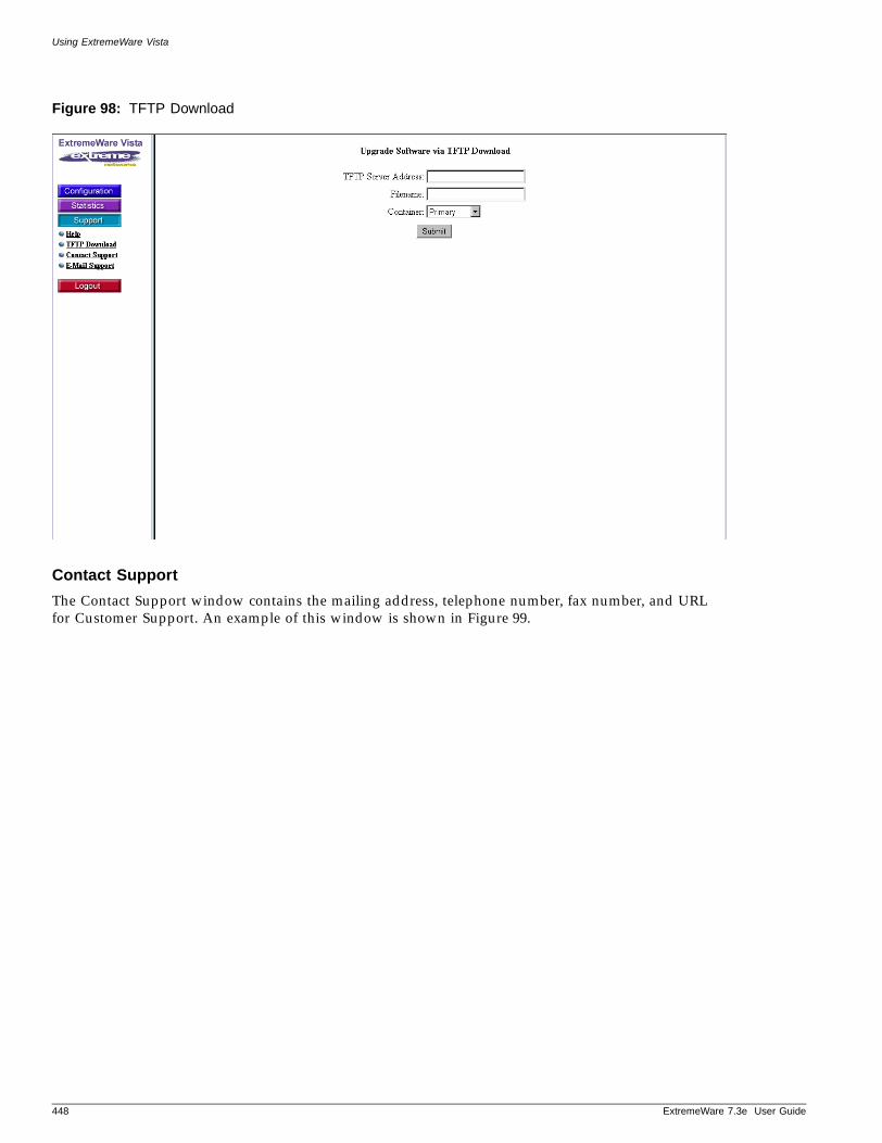
Using ExtremeWare Vista
Figure 98: TFTP Download
Contact Support
The Contact Support window contains the mailing address, telephone number, fax number, and URL for Customer Support. An example of this window is shown in Figure 99.
448 ExtremeWare 7.3e User Guide
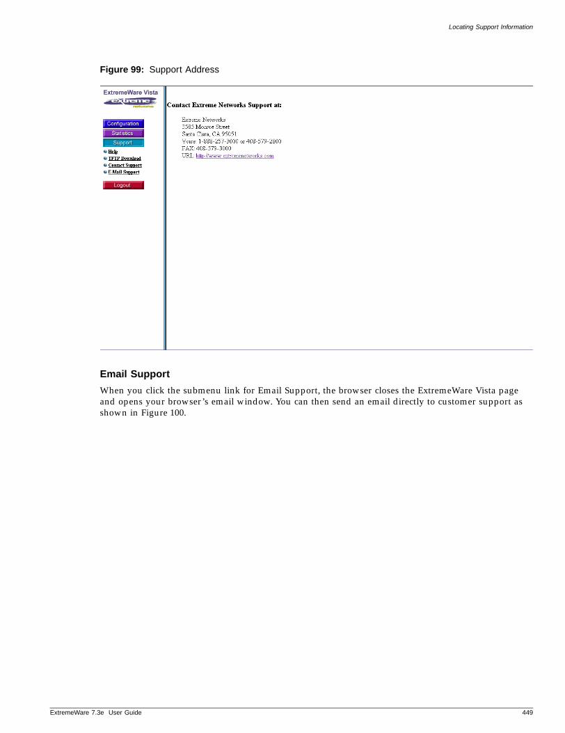
Locating Support Information
ExtremeWare 7
Figure 99: Support Address
Email Support
When you click the submenu link for Email Support, the browser closes the ExtremeWare Vista page and opens your browser’s email window. You can then send an email directly to customer support as shown in Figure 100.
.3e User Guide 449
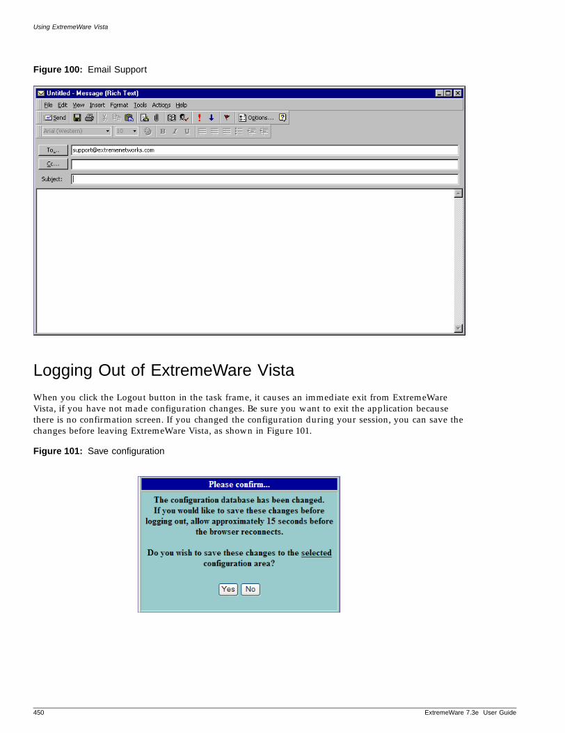
Using ExtremeWare Vista
Figure 100: Email Support
Logging Out of ExtremeWare Vista
When you click the Logout button in the task frame, it causes an immediate exit from ExtremeWare Vista, if you have not made configuration changes. Be sure you want to exit the application because there is no confirmation screen. If you changed the configuration during your session, you can save the changes before leaving ExtremeWare Vista, as shown in Figure 101.
Figure 101: Save configuration
450 ExtremeWare 7.3e User Guide
B Technical Specifications
ExtremeWare 7
This appendix provides additional information on the standards, protocols and MIBs supported by the Summit “e” series of switches. It covers the following topics:
• Supported Protocols, MIBs, and Standards on page 451
Supported Protocols, MIBs, and Standards
The following is a list of software standards and protocols supported by the Summit “e” series of switches:
Denial of Service Protection
RFC 2267 Network Ingress Filtering: Defeating Denial of Service Attacks which employ IP Source Address Spoofing
RPF (Unicast Reverse Path Forwarding) Control
Wire-speed ACLs
Rate Limiting by ACLs
IP Broadcast Forwarding Control
ICMP and IP-Option Response Control
SYN attack protection
Uni-directional Session Control
CERT (http://www.cert.org)
• CA--97.28.Teardrop_Land -Teardrop and “LAND” attack
• IP Options Attack
• CA--98-13-tcp-denial-of-service
• CA--98.01.smurf
• CA--96.26.ping
• CA--96.21.tcp_syn_flooding
• CA--96.01.UDP_service_denial
• CA--95.01.IP_Spoofing_Attacks_and_Hijacked_ Terminal_Connections
• CA-2002-03: SNMP vulnerabilities
Host Attacks
• Syndrop
• Nestea
• Latierra
• Newtear
• Bonk
• Winnuke
• Raped
• Simping
• Sping
• Ascend
• Stream
.3e User Guide 451
Technical Specifications
DiffServ - Standards and MIBs
RFC 2474 Definition of the Differentiated Services Field (DS Field) in the IPv4 and IPv6 Headers
RFC 2475 An Architecture for Differentiated Services
RFC 2597 Assured Forwarding PHB Group
RFC 2598 An Expedited Forwarding PHB
Environmental
EN 300 019-2-1 (2000-09) Storage Class 1.2 - Packaged
EN 300 09-2-2 (1999-09) Transportation Class 2.3 - Packaged
EN 300 019-2-2 (1999-09) Stationary Use at Weather Protected Locations, Class 3.1e - Operational
EN 300 753 (1997-10) Acoustic Noise - Operational
ASTM D5276 Drop - Packaged
ASTM D3332 Shock - Unpackaged
ASTM D3580 Random Vibration - Unpackaged
ASTM D6179 Tilt - Packaged
General Routing and Switching
RFC 1812 Requirements for IP Version 4 Routers
RFC 1519 An Architecture for IP Address Allocation with CIDR
RFC 1256 ICMP Router Discovery Messages
RFC 783 TFTP Protocol (revision 2)
RFC 951 Bootstrap Protocol
RFC 2131 Dynamic Host Configuration Protocol
RFC 1591 Domain Name System Structure and Delegation
RFC 1122 Requirements for Internet Hosts - Communication Layers
RFC 768 User Datagram Protocol
RFC 791 Internet Protocol
RFC 792 Internet Control Message Protocol
RFC 793 Transmission Control Protocol
RFC 826 Ethernet Address Resolution Protocol: Or converting network protocol addresses to 48.bit Ethernet address for transmission on Ethernet hardware
Extreme Standby Router Protocol (ESRP)
IEEE 802.1D-1998 Spanning Tree Protocol
IEEE 802.1W - 2001 Rapid Spanning Tree Protocol
IEEE 802.1Q - 1998 Virtual Bridged Local Area Networks
Ethernet Automatic Protection Switching (EAPS)-Edge mode, master and member of one ring
RFC 3619 Ethernet Automatic Protection Switching (EAPS) Version 1
IP Multicast
RFC 2362 Protocol Independent Multicast-Sparse Mode (PIM-SM): Protocol Specification--two non-passive interfaces
RFC 1112 Host extensions for IP multicasting
RFC 2236 Internet Group Management Protocol, Version 2
IGMP Snooping with Configurable Router Registration Forwarding
Static IGMP Membership
IGMP Filters
Mtrace, draft-letf-idmr-traceroute-imp-07
Mrinfo
452 ExtremeWare 7.3e User Guide
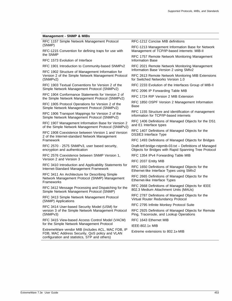
Supported Protocols, MIBs, and Standards
ExtremeWare 7
Management - SNMP & MIBs
RFC 1157 Simple Network Management Protocol (SNMP)
RFC-1215 Convention for defining traps for use with the SNMP
RFC 1573 Evolution of Interface
RFC 1901 Introduction to Community-based SNMPv2
RFC 1902 Structure of Management Information for Version 2 of the Simple Network Management Protocol (SNMPv2)
RFC 1903 Textual Conventions for Version 2 of the Simple Network Management Protocol (SNMPv2)
RFC 1904 Conformance Statements for Version 2 of the Simple Network Management Protocol (SNMPv2)
RFC 1905 Protocol Operations for Version 2 of the Simple Network Management Protocol (SNMPv2)
RFC 1906 Transport Mappings for Version 2 of the Simple Network Management Protocol (SNMPv2)
RFC 1907 Management Information Base for Version 2 of the Simple Network Management Protocol (SNMPv2)
RFC 1908 Coexistence between Version 1 and Version 2 of the Internet-standard Network Management Framework
RFC 2570 - 2575 SNMPv3, user based security, encryption and authentication
RFC 2576 Coexistence between SNMP Version 1, Version 2 and Version 3
RFC 3410 Introduction and Applicability Statements for Internet-Standard Management Framework
RFC 3411 An Architecture for Describing Simple Network Management Protocol (SNMP) Management Frameworks
RFC 3412 Message Processing and Dispatching for the Simple Network Management Protocol (SNMP)
RFC 3413 Simple Network Management Protocol (SNMP) Applications
RFC 3414 User-based Security Model (USM) for version 3 of the Simple Network Management Protocol (SNMPv3)
RFC 3415 View-based Access Control Model (VACM) for the Simple Network Management Protocol
ExtremeWare vendor MIB (includes ACL, MAC FDB, IP FDB, MAC Address Security, QoS policy and VLAN configuration and statistics, STP and others)
RFC-1212 Concise MIB definitions
RFC-1213 Management Information Base for Network Management of TCP/IP-based internets: MIB-II
RFC 1757 Remote Network Monitoring Management Information Base
RFC 2021 Remote Network Monitoring Management Information Base Version 2 using SMIv2
RFC 2613 Remote Network Monitoring MIB Extensions for Switched Networks Version 1.0
RFC 2233 Evolution of the Interfaces Group of MIB-II
RFC 2096 IP Forwarding Table MIB
RFC 1724 RIP Version 2 MIB Extension
RFC 1850 OSPF Version 2 Management Information Base
RFC 1155 Structure and identification of management information for TCP/IP-based internets
RFC 1406 Definitions of Managed Objects for the DS1 and E1 Interface types
RFC 1407 Definitions of Managed Objects for the DS3/E3 Interface Type
RFC 1493 Definitions of Managed Objects for Bridges
Draft-letf-bridge-rstpmib-03.txt – Definitions of Managed Objects for Bridges with Rapid Spanning Tree Protocol
RFC 1354 IPv4 Forwarding Table MIB
RFC 2037 Entity MIB
RFC 1650 Definitions of Managed Objects for the Ethernet-like Interface Types using SMIv2
RFC 2665 Definitions of Managed Objects for the Ethernet-like Interface Types
RFC 2668 Definitions of Managed Objects for IEEE 802.3 Medium Attachment Units (MAUs)
RFC 2787 Definitions of Managed Objects for the Virtual Router Redundancy Protocol
RFC 2795 Infinite Monkey Protocol Suite
RFC 2925 Definitions of Managed Objects for Remote Ping, Traceroute, and Lookup Operations
RFC 1643 Ethernet MIB
IEEE-802.1x MIB
Extreme extensions to 802.1x-MIB
.3e User Guide 453
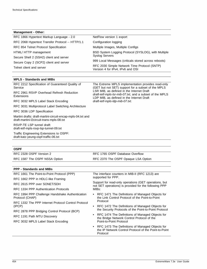
Technical Specifications
Management - Other:
RFC 1866 Hypertext Markup Language - 2.0
RFC 2068 Hypertext Transfer Protocol -- HTTP/1.1
RFC 854 Telnet Protocol Specification
HTML/ HTTP management
Secure Shell 2 (SSH2) client and server
Secure Copy 2 (SCP2) client and server
Telnet client and server
NetFlow version 1 export
Configuration logging
Multiple Images, Multiple Configs
BSD System Logging Protocol (SYSLOG), with Multiple Syslog Servers
999 Local Messages (criticals stored across reboots)
RFC 2030 Simple Network Time Protocol (SNTP) Version 4 for IPv4, IPv6 and OSI
MPLS - Standards and MIBs
RFC 2212 Specification of Guaranteed Quality of Service
RFC 2961 RSVP Overhead Refresh Reduction Extensions
RFC 3032 MPLS Label Stack Encoding
RFC 3031 Multiprotocol Label Switching Architecture
RFC 3036 LDP Specification
Martini drafts: draft-martini-circuit-encap-mpls-04.txt and draft-martini-l2circuit-trans-mpls-08.txt
RSVP-TE LSP tunnel draft: draft-ietf-mpls-rsvp-lsp-tunnel-09.txt
Traffic Engineering Extensions to OSPF: draft-katz-yeung-ospf-traffic-06.txt
The Extreme MPLS implementation provides read-only (GET but not SET) support for a subset of the MPLS LSR MIB, as defined in the Internet Draft draft-ietf-mpls-lsr-mib-07.txt, and a subset of the MPLS LDP MIB, as defined in the Internet Draft draft-ietf-mpls-ldp-mib-07.txt.
OSPF
RFC 2328 OSPF Version 2
RFC 1587 The OSPF NSSA Option
RFC 1765 OSPF Database Overflow
RFC 2370 The OSPF Opaque LSA Option
PPP - Standards and MIBs
RFC 1661 The Point-to-Point Protocol (PPP)
RFC 1662 PPP in HDLC-like Framing
RFC 2615 PPP over SONET/SDH
RFC 1334 PPP Authentication Protocols
RFC 1994 PPP Challenge Handshake Authentication Protocol (CHAP)
RFC 1332 The PPP Internet Protocol Control Protocol (IPCP)
RFC 2878 PPP Bridging Control Protocol (BCP)
RFC 1191 Path MTU Discovery
RFC 3032 MPLS Label Stack Encoding
The interface counters in MIB-II (RFC 1213) are supported for PPP.
Support for read-only operations (GET operations, but not SET operations) is provided for the following PPP MIBs:
• RFC 1471 The Definitions of Managed Objects for the Link Control Protocol of the Point-to-Point Protocol
• RFC 1472 The Definitions of Managed Objects for the Security Protocols of the Point-to-Point Protocol
• RFC 1474 The Definitions of Managed Objects for the Bridge Network Control Protocol of the Point-to-Point Protocol
• RFC 1473 The Definitions of Managed Objects for the IP Network Control Protocol of the Point-to-Point Protocol
454 ExtremeWare 7.3e User Guide
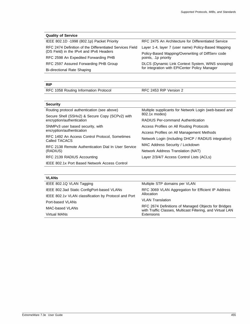
Supported Protocols, MIBs, and Standards
ExtremeWare 7
Quality of Service
IEEE 802.1D -1998 (802.1p) Packet Priority
RFC 2474 Definition of the Differentiated Services Field (DS Field) in the IPv4 and IPv6 Headers
RFC 2598 An Expedited Forwarding PHB
RFC 2597 Assured Forwarding PHB Group
Bi-directional Rate Shaping
RFC 2475 An Architecture for Differentiated Service
Layer 1-4, layer 7 (user name) Policy-Based Mapping
Policy-Based Mapping/Overwriting of DiffServ code points, .1p priority
DLCS (Dynamic Link Context System, WINS snooping) for integration with EPICenter Policy Manager
RIP
RFC 1058 Routing Information Protocol RFC 2453 RIP Version 2
Security
Routing protocol authentication (see above)
Secure Shell (SSHv2) & Secure Copy (SCPv2) with encryption/authentication
SNMPv3 user based security, with encryption/authentication
RFC 1492 An Access Control Protocol, Sometimes Called TACACS
RFC 2138 Remote Authentication Dial In User Service (RADIUS)
RFC 2139 RADIUS Accounting
IEEE 802.1x Port Based Network Access Control
Multiple supplicants for Network Login (web-based and 802.1x modes)
RADIUS Per-command Authentication
Access Profiles on All Routing Protocols
Access Profiles on All Management Methods
Network Login (including DHCP / RADIUS integration)
MAC Address Security / Lockdown
Network Address Translation (NAT)
Layer 2/3/4/7 Access Control Lists (ACLs)
VLANs
IEEE 802.1Q VLAN Tagging
IEEE 802.3ad Static ConfigPort-based VLANs
IEEE 802.1v VLAN classification by Protocol and Port
Port-based VLANs
MAC-based VLANs
Virtual MANs
Multiple STP domains per VLAN
RFC 3069 VLAN Aggregation for Efficient IP Address Allocation
VLAN Translation
RFC 2674 Definitions of Managed Objects for Bridges with Traffic Classes, Multicast Filtering, and Virtual LAN Extensions
.3e User Guide 455

Technical Specifications
456 ExtremeWare 7.3e User Guide

ExtremeWare 7.3e User Guide
Index
Numerics802.11a, 802.11b, 802.11g 362802.1d mode, STP 267802.1p 109 to 111802.1q 239802.1x authentication
co-existence with web-based 157EAPOL flooding 63overview 156requirements 156
802.1x/EAP 170802.3ad load sharing 71
AAbout This Guide 18access control lists
adding 148deleting 148description 145, 429examples 149ICMP filter example 152permit-established example 149permit-established keyword 147verifying settings 148
access levels 35, 408access masks 148access policies 353access profile mode 196access profiles
reverse mask 196SNMP 48Telnet 45
AccessAdapt management 362accounts 35 to 38ACL, installed by DoS protect 206active scan 369adding
access lists 148access masks 148log filters 133ports to a VLAN 429rate limits 148
Address Resolution Protocol. See ARPadmin account 36Advanced Edge license 411Advanced Encryption Standard. See AES
AES 362agent circuit ID sub-option 330agent remote ID sub-option 330aging entries, FDB 98aging value of DoS protection 209alarm actions 142Alarms, RMON 141Altitude 300 361Altitude 300 antenna 362Altitude 300-2d 363antenna, Altitude 300 362AP detection 369AP scan
configuring 369enabling and disabling 369results (table) 371viewing results 371
APMAC 371areas, OSPF 338ARP
communicating with devices outside subnet 325configuring proxy 325ExtremeWare Vista 431incapable device 325minimal mode 241proxy ARP between subnets 325proxy ARP, description of 324responding to ARP requests 325table, displaying 327
atestReceivedEngineTime 53authentication 170
location-based 171network access examples (table) 173time-based 171web-based & 802.1x 156
authentication methods 157802.1x/EAP 170open 170WEP 170
authentication type 375AuthnoPriv 55AuthPriv 55automatic failover 79 to 80autonegotiation 66autopolarity 67
457

Index
Bbackbone area, OSPF 338beacon interval 366, 367beacons, number of 371blackhole entries, FDB 99, 153blackhole MAC addresses 109blocking attacks 206BOOTP relay
configuring 329 to 330deleting 329ExtremeWare Vista 436UDP-forwarding 331
BOOTP server 43BootROM
image 223minimal mode 241prompt 232signature compatibility 228upgrading, accessing 231
bootstrap router (BSR) 352bridging, wireless 363broadcast forwarding 410browser
controls 409fonts 406setting up 405
buttons in ExtremeWare Vista 409
Ccable diagnostics 236cabling for redundancy 81campus mode 162campus mode authentication 158capability, value in AP scan results 371channel 371checksum computation 353cipher suites 171classification, port power 388clearing the client scan table 373CLI
command history 33command shortcuts 30line-editing keys 32named components 31numerical ranges, BlackDiamond switch 31numerical ranges, Summit switch 31symbols 31syntax helper 30troublehooting 237using 29
clientaging 377collecting history information 374current state 374current state details (table) 375diagnostic and history information (table) 376history information 375scan 372scan performance results (table) 374scan results (table) 373
client MAC 375client priority 375client scan table, clearing 373client scanning
458
clearing client scan table 373configuring 372overview 372viewing properties 373viewing scan results 373
client VLAN 375collisions 442combination ports 80command
history 33shortcuts 30
Command-Line Interface. See CLIcommon commands (table) 33common power pool 387communicating with devices outside subnet 325complete configuration download 230configuration
downloading 230logging 140network login 161primary and secondary 228saving changes 228schedule download 231security options (table) 178uploading to file 229using ExtremeWare Vista 409wireless ports 378
configuring PoE 393console port
enable telnet 46supported sessions 42
content frame in ExtremeWare Vista 408controlling Telnet access 45conventions 18country codes, configuring for wireless 377CPU utilization 241CRC errors 238creating
access lists 148access masks 148OSPF areas using ExtremeWare Vista 413rate limits 148user accounts 37
creating rules, NAT 122
Ddatabase applications, and QoS 105database overflow, OSPF 337debug mode for EMS 240debug tracing facility 240default
gateway 309passwords 36routes 238settings 27STP domain 266users 36
default gateway 378default route 240default VLAN 91delete
access list 148access masks 148access profile 198
ExtremeWare 7.3e User Guide

Index
BOOTP relay 329EAPS domain 252filter 57group 54MIB view 56OSPF area using ExtremeWare Vista 412rate limit 148session 45SNMP notification tags 58SNMP target 56target parameters 57trap receiver 47user 37, 53
delivery traffic indication message (DTIM) 366, 368denial of service protection 202 to 209
aging value 209configuring 202deploying 205disabling 204displaying 204drop probability rates 207enabling 203enhanced 206IPFDB cache size 209IPFDB learning qualifier 208learn windows 207, 209learning limit 209setting protocol types 208setting thresholds 207SQL slammer 206trusted and untrusted ports 207, 209
deploying denial of service protection 205DHCP
network login and 156option 82 330relay 329, 330requirement for web-based network login 156server, used as part of network login 165UDP-forwarding 331verifying relay configuration 330
DiffServ, configuring 111disabling route advertising (RIP) 336disconnecting a Telnet session 45distance-vector protocol, description 334DNS, description 38Domain Name Service. See DNSdomains, STP 266DoS protection. See denial of service protectiondownloading incremental configuration 230drop probability rates 207DTIM 366, 368dynamic entries, FDB 98, 153dynamic routes 323
EEAP
EAPOL 63IEEE 802.1x port authentication 63
EAP-MD5 362EAPOL and DHCP 157EAPOL flooding 63EAPS
common link 258domain, creating and deleting 251
ExtremeWare 7.3e User Guide
enabling and disabling a domain 255enabling and disabling on a switch 255multi-ring topologies 250polling timers, configuring 252restrictions 251ring port, unconfiguring 255shared port
configuration rules 263configuring the domain ID 262creating and deleting 261defining the mode 261
shared port, common link failure 260shared ports 258show eaps display fields (table) 257status information, displaying 255 to 258, 262switch mode, defining 252
EAPS awareness 251EAP-TLS 362EAP-TLS (Transport Layer Security) 171EAP-TTLS 362EAP-TTLS (Tunneled TLS) 171echo server 332EDP, description 76ELRP
description 301master behavior 302pre-master behavior 302terms 301
EMISTPdescription 267rules 270
enabling a switch port 66encryption 171encryption type 375Enhanced DoS Protection 206Equal Cost Multi-Path (ECMP) routing. See IP route sharingerror level messages in ExtremeWare Vista 409errors, port 126ESRP
and IP multinetting 307and STP 307and VLAN aggregation 295and VRRP 314description 285diagnostic tracking 291direct link 288domains 297don’t count 297environment tracking 291example 304failover time 290groups 298host attach 296linking switches 288load sharing 297master
behavior 289definition 287determining 288electing 289election algorithms 290
multiple VLANs sharing a host port 288OSPF tracking 293ping tracking 292, 293
459

Index
port restart 295pre-master, behavior 289restarting ports 295RIP tracking 293route table tracking 292selective forwarding 299slave mode
behavior 289definition 287
super-VLAN 295terms 286tracking, description 291
ESRP, load sharing and 73ESS name 371ESSID 375establishing a Telnet session 43Ethernet collisions 442Ethernet link errors 443Ethernet packet encapsulation 110Events, RMON 141examples
port power budget 389security configuration 180wireless configuration 178
explicit packet marking 109export restrictions 27exporting routes to OSPF 412Extended Service Set Identifier. See ESSIDExtensible Authentication Protocol. See EAPExternal Power Supply EPS-LD 390Extreme Discovery Protocol See EDPExtreme Loop Recovery Protocol. See ELRPExtreme Standby Router Protocol. See ESRPExtreme Unified Access Architecture 362ExtremeWare
factory defaults 27features 23
ExtremeWare Vista 405 to 450access levels 408accessing 406browser controls 409browser setup 405buttons 409Ethernet collisions 442event logging 432FDB 433fonts 406frames 408hardware status 445home page 406IP ARP 434IP configuration statistics 435IP forwarding configuration 410IP routing table statistics 437IP statistics 438JavaScript 405license window 411link errors 443logging out 450navigating 408OSPF configuration 412overview 405port configuration 417port statistics 441
460
port utilization 443requirements 405RIP configuration 419RIP statistics 444screen resolution 406SNMP configuration 421status messages 409STP configuration 422support information 446switch configuration 425user account 426username, password 407VLAN administration 427
FFDB 97 to 101
adding an entry 97aging entries 98blackhole entries 99contents 97creating a permanent entry example 100displaying 101dynamic entries 98dynamic entries, limiting 153entries 97limiting entries 153non-aging entries 98permanent entries 99prioritizing entries 153QoS profile association 99reviewing through ExtremeWare Vista 433troubleshooting 238, 240
fiber, troubleshooting 239file server applications, and QoS 105flow control 66fonts, browser 406force disassociation 380Forwarding Database. See FDBfragment length 366, 368fragment size 366, 368frames in ExtremeWare Vista 408
Ggateway, default 378Greenwich Mean Time Offsets (table) 61groups 54
Hhardware status information 445health check reset 379hello interval 353history command 33History, RMON 141home page 406host attach 73HTTP clients 175HTTPS 175
IICMP attacks 206IEEE 802.1Q 86IEEE 802.1x
ExtremeWare 7.3e User Guide
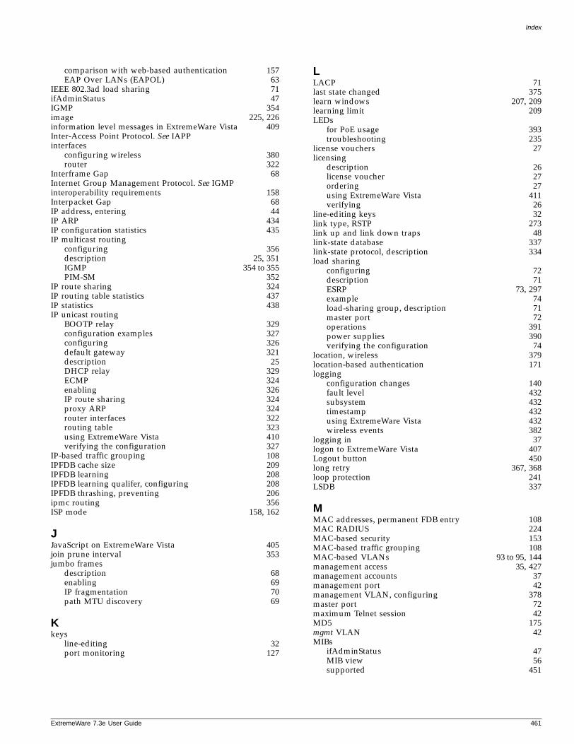
Index
comparison with web-based authentication 157EAP Over LANs (EAPOL) 63
IEEE 802.3ad load sharing 71ifAdminStatus 47IGMP 354image 225, 226information level messages in ExtremeWare Vista 409Inter-Access Point Protocol. See IAPPinterfaces
configuring wireless 380router 322
Interframe Gap 68Internet Group Management Protocol. See IGMPinteroperability requirements 158Interpacket Gap 68IP address, entering 44IP ARP 434IP configuration statistics 435IP multicast routing
configuring 356description 25, 351IGMP 354 to 355PIM-SM 352
IP route sharing 324IP routing table statistics 437IP statistics 438IP unicast routing
BOOTP relay 329configuration examples 327configuring 326default gateway 321description 25DHCP relay 329ECMP 324enabling 326IP route sharing 324proxy ARP 324router interfaces 322routing table 323using ExtremeWare Vista 410verifying the configuration 327
IP-based traffic grouping 108IPFDB cache size 209IPFDB learning 208IPFDB learning qualifer, configuring 208IPFDB thrashing, preventing 206ipmc routing 356ISP mode 158, 162
JJavaScript on ExtremeWare Vista 405join prune interval 353jumbo frames
description 68enabling 69IP fragmentation 70path MTU discovery 69
Kkeys
line-editing 32port monitoring 127
ExtremeWare 7.3e User Guide
LLACP 71last state changed 375learn windows 207, 209learning limit 209LEDs
for PoE usage 393troubleshooting 235
license vouchers 27licensing
description 26license voucher 27ordering 27using ExtremeWare Vista 411verifying 26
line-editing keys 32link type, RSTP 273link up and link down traps 48link-state database 337link-state protocol, description 334load sharing
configuring 72description 71ESRP 73, 297example 74load-sharing group, description 71master port 72operations 391power supplies 390verifying the configuration 74
location, wireless 379location-based authentication 171logging
configuration changes 140fault level 432subsystem 432timestamp 432using ExtremeWare Vista 432wireless events 382
logging in 37logon to ExtremeWare Vista 407Logout button 450long retry 367, 368loop protection 241LSDB 337
MMAC addresses, permanent FDB entry 108MAC RADIUS 224MAC-based security 153MAC-based traffic grouping 108MAC-based VLANs 93 to 95, 144management access 35, 427management accounts 37management port 42management VLAN, configuring 378master port 72maximum Telnet session 42MD5 175mgmt VLAN 42MIBs
ifAdminStatus 47MIB view 56supported 451
461

Index
Microsoft Internet Explorer, using for ExtremeWare Vista406minimal mode 241modular switch, enabling and disabling ports 66monitoring the switch 125mrinfo 355mtrace 356multicast forwarding 410multicast tools 355multiple routes 323multi-ring topologies 250
Nnames, VLANs 90NAT 117 to 123Netscape Navigator, using for ExtremeWare Vista 406Network Address Translation. See NATnetwork login 156
authentication types 156campus mode 164configuring 161DHCP server as part of 165disabling 166introduction 59settings, displaying 166, 167
network policies 363network security policies 172network type 371noAuthnoPriv 54noise floor 368non-aging entries, FDB 98notice icons 18Not-So-Stubby_Area. See NSSANSSA 339
Ooff-channel scan 369opaque LSAs, OSPF 338open authentication 170Open Shortest Path First. See OSPFopening a Telnet session 43option 82, DHCP relay 330Organizational Unique Identifier (OUI) 168OSPF
advantages 334area 0 338areas 338backbone area 338configuration example 345configuration using ExtremeWare Vista 412consistency 337database overflow 337description 334, 336display filtering 347exporting routes using ExtremeWare Vista 412link type 341link-state database 337normal area 340NSSA 339opaque LSAs 338passive 337point-to-point links 341redistributing routes 342router types 338
462
routing access policies 200settings, displaying 347stub area 339virtual link 340wait interval, configuring 344
Ppacket fragment size 366, 368packet preamble 367, 368passive OSPF 337passive scan 369password problems 238passwords
default 36forgetting 37
path MTU discovery 69PD 385, 388PEAP 362PEAP (protected EAP) 171performance enhanced DoS Protection 206permanent entries, FDB 99permanent MAC addresses 108permit-established keyword 147Per-VLAN Spanning Tree. See PVST+PIM-SM 352 to 353ping command 38PoE 385 to 402
budget 386configuring 393features 385LEDs for usage 393
poison reverse 335policy examples 173port
autonegotiation 66configuring 418connection order 387enabling and disabling 66errors,viewing 126mode 267, 282monitoring display keys 127network login 156numbering 65personality 362power
budget 388, 389management 386operator limit 386priorities 388reset 388
priority, STP 282receive errors 127software-controlled redundant
configuring 79description 77
statistics, viewing 125, 441STP state, displaying 284transmit errors 126troubleshooting 238utilization 443
port-based VLANs 84port-mirroring 75power
budget management 386
ExtremeWare 7.3e User Guide

Index
common pool 387consuming more than allocated 389load sharing operations 391load sharing supplies 390modes 392operator limit 386parameter restrictions (table) 392, 393port 386port budget example 389port connection order 387port power budget 388port priorities 388port reset 388power events 389redundant supplies 391reserved 386
power events 389Power over Ethernet. See PoEpower sourcing equipment (PSE) 388power supplies (table) 391powered device 385preamble 367, 368primary image 226priority for slow path traffic 111privacy 171private community, SNMP 48private keys 176PROBE REQ messages 372probe resp packets, number of 371profile
QoS 106RF 364, 365security 364
protocol analyzers, use with port-mirroring 75protocol filters 89Protocol Independent Multicast- Sparse Mode. See PIM-SMprotocol-based VLANs 88proxy ARP 324 to 325public community, SNMP 48PVST+
description 271STP mode 267
QQoS 103 to 115
802.1p default mapping (table) 110802.1p priority 110applications 104blackhole 109database applications 105default QoS profiles 106description 24, 103DiffServ, configuring 111FDB entry association 99file server applications 105monitor 113priority 106profile 106 to 107profiles parameters (table) 106traffic groupings 106traffic groupings by precedence (table) 107verifying 114video applications 104voice applications 104
ExtremeWare 7.3e User Guide
web browsing applications 105Quality of Servce. See QoS 104
RRadio Frequency See RFRADIUS
and TACACS+ restriction 58client configuration 213description 58, 211Merit server configuration (example) 215per-command authentication 212per-command configuration (example) 216request attributes (table) 173RFC 2138 attributes 213servers 211TCP port 213wireless attributes 173
rapid root failover 267Rapid Spanning Tree Protocol. See RSTPrate limit protocol type 208rate limits
adding 148and QoS 115deleting 148
real-time performance monitoring 113reboot loop protection 241receive errors 127received signal strength 375redistributing routes 342redundant Gigabit uplink port
Summit 200-24 rules 79Summit 200-48 rules 80
redundant ports, software controlledconfiguring 79
redundant ports, software-controlleddescription 77typical configurations 77
redundant power supplies 391relay agent option, DHCP option 82 330Remote Monitoring. See RMONrenaming a VLAN 91rendezvous point (RP) 352request to send (RTS) threshold 367, 368requirements for ExtremeWare Vista 405reserved power 386reset to factory defaults 229responding to ARP requests 325reverse mask 196RF
monitoring 368profiles 365properties 365
RF profile 364configuring 366creating 365deleting 366property values (table) 367viewing properties 367
RIPadvantages 334configuration example 343configuration using ExtremeWare Vista 419description 334, 335disabling route advertising 336
463

Index
enabling 326limitations 334poison reverse 335redistributing routes 342routing access policies 198routing table entries 335split horizon 335statistics 444triggered updates 336version 2 336
RMONalarm actions 142Alarms group 141Events group 141features supported 140History group 141probe 140Statistics group 141
route sharing. See IP route sharingrouter interfaces 322router licensing
description 26license voucher 27ordering 27verifying 26
router types, OSPF 338routing access policies
access profile 196 to 198deny 196none 196OSPF 200permit 196PIM 201RIP 198using 195
Routing Information Protocol. See RIProuting table, populating 323routing. See IP unicast routingRSS 375RSS statistics 371RSTP
alternate port 272auto link 273backup port 272broadcast link 273configuring link types 273designated port 272designated port rapid behavior 276edge link 273edge ports 273operation 274overview 271point-to-point link 273port roles 272propogating topology information 277receiving bridge behavior 277root port 272root port rapid behavior 275terms 271timers 273
RTSthreshold 367, 368
rule matching, NAT 122Rx bytes 375
464
RX CRC errors 238Rx frames 375
Ssample configuration 162saving configuration changes 228scan for AP detection 369scheduling configuration download 231screen resolution, ExtremeWare Vista 406secondary image 226security
authentication 170certificates 176configuration examples 180configuration options (table) 178options (table) 169
security licensingdescription 27obtaining 27
security name 53security policies 172
and RADIUS support 173design 172
security profile 364sessions, deleting 45short retry 367, 368shortcuts, command 30shortest path tree (SPT) 352, 353Simple Network Management Protocol. See SNMPslow path traffic 111smart redundancy 77SNAP protocol 90SNMP
community strings 48configuring 47, 421controlling access 48filters 57ifAdminStatus MIB value 47Network Manager troubleshooting 237notification tags 58read access 48read/write access 48settings, displaying 49supported MIBs 47system contact 48, 421system location 48, 421system name 48, 421targets 56trap receiver 237trap receivers 47using 46
SNMPEngineBoots 53snmpEngineID 52SNMPEngineTime 53SNTP
configuring 59Daylight Savings Time 59description 59example 62Greenwich Mean Time offset 59Greenwich Mean Time Offsets (table) 61NTP servers 59
software licensingsecurity features 27
ExtremeWare 7.3e User Guide

Index
SSH2 protocol 27using ExtremeWare Vista 411
software-controlled redundant portstypical configuration 77
Spanning Tree Protocol. See STPspeed, ports 66split horizon 335SQL slammer DoS attacks 206SSH2 protocol
authentication key 222description 46, 221enabling 222licensing 27predefined clients 222TCP port number 222
standalone buttons in ExtremeWare Vista 409stand-alone switch
enabling and disabling ports 66static IGMP 354static routes 238, 323statistics
port 125reports using ExtremeWare Vista 431RMON 141
status monitoringdescription 125
STP802.1d mode 267and ESRP 307and VLANs 266and VRRP 314basic configuration example 268bridge priority 282configurable parameters 282configuration examples 282configuring 281, 422description 24displaying settings 283domains 266EAPS awareness 251EMISTP
description 267rules 270
forward delay 282hello time 282max age 282overview 265path cost 282port mode 267, 282port priority 282port state, displaying 284PVST+ mode 267, 271rapid root failover 267requirement for multi-ring topologies 251rules and restrictions 281StpdID 267, 282troubleshooting 240
STPD modes 266stub area, OSPF 339sub-options, DHCP relay agent option 330super-VLAN 295supplicant side requirements 158support information 446supported rate set 371
ExtremeWare 7.3e User Guide
SVP, enabling to support VoIP 382switch
configuration using ExtremeWare Vista 425configuring load sharing 72configuring wireless properties 377monitoring 125RMON features 140
switch port-mirroning 75Symmetric ciphers 175system contact, SNMP 48, 421system location, SNMP 48, 421system name, SNMP 48, 421system odometer 241
TTACACS+
and RADIUS restriction 58description 59, 217servers, specifying 217
tagging, VLAN 86task frame in ExtremeWare Vista 408technical support 242Telnet
connecting to another host 43controlling access 45disconnecting a session 45maximum sessions 42opening a session 43problems 237using 42
Temporal Key Integrity Protocol. See TKIPTerminal Access Controller Access Control System Plus. See
TACACS+TFTP
server 225using 229
thrashing, IPFDB, preventing 206threshold, RTS 367, 368time-based authentication 171timed configuration download, MAC-based VLANs 95timers, PIM-SM 353TKIP 362traceroute command 39traffic groupings 106traffic rate-limiting 115transmit errors 126trap receivers 237triggered updates 336troubleshooting
cables 236CLI 237CPU utilization 241FDB 240fiber 239IP multicast 355password 238permanent FDB entries 238power 235reboot loops 241STP 240technical support 242VLANs 239
trunks 86trusted neighbor policy 353
465

Index
trusted OUI 168trusted ports 207, 209Tx bytes 375Tx frames 375
UUDP echo server 332UDP-forwarding 331unconfigure RIP 419unicast forwarding 410unified access security 168untrusted ports 207, 209uplink redundancy 79 to 80uploading the configuration 229URL redirection 157user accounts 36, 426user login 164user name 53users
access levels 35accounts 158authenticating 58, 211creating 37default 36viewing 37
USM security 54UTP problems 236
Vvendor ID 158Vendor Specific Attribute (VSA) 158vendor specific attributes (table) 174verifying load sharing 74video applications, and QoS 104viewing accounts 37Virtual LANs. See VLANsvirtual link, OSPF 340virtual router, VRRP 310Vista See ExtremeWare VistaVLANs
administration using ExtremeWare Vista 427and ExtremeWare Vista 405and STP 266assigning a tag 86benefits 83configuration examples 92configuring 91default 91description 24disabling route advertising 336displaying settings 93IP fragmentation 70MAC-based 93 to 95, 144management 378mgmt 42mixing port-based and tagged 88names 90network login 156port-based 84protocol filters 89protocol-based 88renaming 91routing 326
466
tagged 86tagging 86troubleshooting 239trunks 86types 84UDP-forwarding 331
voice applications, QoS 104VRRP
advertisement interval 313, 317and ESRP 314and Spanning Tree 314backup router 310configuration parameters (table) 317default gateway 309description 309electing the master 313examples 318interfaces 310IP address 310, 317IP address owner 310MAC address 310 to 315master down interval 313, 317master router 310master, determining 310multicast address 313operation 314ping tracking 311port restart 314preempt mode 317priority 310 to 317redundancy 315restarting ports 314route table tracking 311skew time 313, 317tracking, description 310virtual router 310virtual router identifier (VRID) 310, 317virtual router MAC address 310 to 315VLAN tracking 311VRRP router 310
VSA definitions for network login (table) 158
Wwarning level messages in ExtremeWare Vista 409web browsing applications, and QoS 105web login access 175web-based and 802.1x authentication 157web-based authentication 156WEP authentication supported 371WEP required 371Wi-Fi protected access (WPA) 172wi-fi security cipher suites (table) 171wired equivalent privacy (WEP) authentication 170wireless
bridging 363client aging 377client current state 374client history statistics 374client scanning 372configuration examples 178, 179configuring interfaces 380country codes 377default gateway 378device management 364
ExtremeWare 7.3e User Guide

Index
enabling SVP 382event logging and reporting 382example network 362features 362health check reset 379location 379management VLAN 378network policies 363networking overview 361RF profile, configuring 366RF profile, creating 365RF profile, deleting 366show commands 364switch properties, configuring 377
wireless client history information 375wireless port value in client state table 375wireless ports
configuration process 364configuration property values (table) 379configuring 378managing 364
wireless user access security 169, 170WPA 362, 371
Xxmodem 225
ExtremeWare 7.3e User Guide
467
Index
468
ExtremeWare 7.3e User Guide
ExtremeWare 7
Index of Commands
Numerics802.3af 385
Cclear counters 137, 216clear debug-trace 240clear fdb 109clear inline-power connection-history slot 387, 395clear inline-power fault ports 397clear inline-power stats ports 397, 398clear ipmc cache 206clear log counters 137clear session 33, 45clear wireless ports interface ap-scan results 371clear wireless ports interface client-scan counters 374clear wireless ports interface client-scan results 374client scanning
enabling and disabling 372config inline-power detection 397config inline-power display-string 398config inline-power reserved budget 395, 397config inline-power usage-threshold 395configure acacs-accounting shared-secret 219configure access-profile add 196configure access-profile delete 198configure access-profile mode 196configure account 33configure auth mgmt-access radius primary 220configure auth mgmt-access radius-accounting prima-
ry 220configure auth mgmt-access tacacs primary 220configure auth mgmt-access tacacs-accounting primary
221configure auth netlogin radius primary 221configure auth netlogin radius-accounting primary 221configure auth netlogin tacacs primary 221configure auth netlogin tacacs-accounting primary 221configure banner 33
configure banner netlogin 33configure bootprelay add 329configure bootprelay delete 329configure bootprelay dhcp-agent information check
330configure bootprelay dhcp-agent information option
330configure bootprelay dhcp-agent information policy
330configure cpu-dos-protect 203configure cpu-dos-protect trusted-ports 205configure debug-trace wireless ports iapp 382configure dns-client add 38configure dns-client default-domain 38configure download server 95, 231configure dvmrp vlan export-filter 201configure eaps add protect vlan 255configure eaps failtime 249, 252configure eaps failtime expiry-action 249, 252configure eaps hellotime 252configure eaps mode 252configure eaps primary port 254configure eaps secondary port 254configure eaps shared-port domain 262configure eaps shared-port mode 261configure enhanced-dos-protect ipfdb agingtime 209configure enhanced-dos-protect ipfdb cache-size 209configure enhanced-dos-protect ipfdb learn-limit 209configure enhanced-dos-protect ipfdb learn-window
209configure enhanced-dos-protect ports 207, 209configure enhanced-dos-protect rate-limit 207, 208configure esrp port-mode ports 297configure fdb agingtime 101configure igmp snooping add static group 354configure igmp snooping add static router 355configure igmp snooping delete static group 355configure igmp snooping delete static router 355configure igmp snooping filter 355
.3e User Guide 469
Index of Commands
configure inline-power operator-limit ports 389configure inline-power power-supply 392configure inline-power priority ports 388configure inline-power violation-precedence 389configure iparp add proxy 325configure ip-mtu vlan 69, 70configure iproute add default 42, 45, 326configure iproute priority 326configure jumbo-frame size 69configure log display 139configure log filter 133configure log filter events match 135configure log target filter 131, 135configure log target format 136configure log target match 134configure mirroring add 75configure nat add vlan map source 120, 121, 122configure nat vlan 118configure netlogin base-url 166configure netlogin redirect-page 166configure osfp area nssa 339configure osfp area stub 339configure osfp ase-limit 337configure ospf area external-filter 200configure ospf area interarea-filter 200configure ospf asbr-filter 200configure ospf direct-filter 200, 343configure ospf vlan area 339configure ospf vlan timer 344configure pim add 352, 356configure pim crp static 353configure pim delete vlan 352configure pim register-checksum-to 353configure pim spt-threshold 353configure pim timer 353configure pim vlan 353configure pim vlan trusted-gateway 201configure port interpacket-gap 68configure ports auto off 33, 66configure ports auto on 67configure ports auto-polarity off 67configure ports auto-polarity on 67configure ports lock-learning 155configure ports preferred-medium 81configure ports redundant 79configure ports unlimited-learning 154configure ports unlock-learning 155configure protocol add 90configure radius server 218configure radius server client-ip 211configure radius server timeout 219configure radius shared-secret 211, 212, 218configure radius timeout 211configure radius-accounting 212
configure radius-accounting server client-ip 218configure radius-accounting server timeout 219configure radius-accounting shared-secret 219configure radius-accounting timeout 212configure reboot-loop-protection threshold 241configure rf-profile beacon-interval 366configure rf-profile dtim-interval 366configure rf-profile frag-length 366configure rf-profile long-retry 367configure rf-profile preamble 367configure rf-profile rts-threshold 367configure rf-profile short-retry 367configure rip vlan export-filter 199configure rip vlan import-filter 199configure rip vlan trusted-gateway 198configure security-profile default-user-vlan 174configure security-profile dot1x-upa-timers pair-
wise-update-timer 174configure security-profile ess-name 174configure security-profile ssid-in-beacon 174configure security-profile use-dynamic-vlan 174configure security-profile wep key delete 174configure security-rofile dot11-auth 174configure sharing address-based 72configure snmp add community 47configure snmp add trapreceiver community 47configure snmp add trapreceiver community
trap-group 50configure snmp delete trapreceiver 47configure snmp readonly access-profile 48configure snmp readwrite access-profile 48configure snmpv3 add access 54configure snmpv3 add filter subtree type 57configure snmpv3 add filter-profile param 57configure snmpv3 add group user 54configure snmpv3 add mib-view 55configure snmpv3 add mib-view subtree 55configure snmpv3 add notify tag 58configure snmpv3 add target-addr param ipaddress 56configure snmpv3 add target-params 52configure snmpv3 add user 53configure snmpv3 delete access 54configure snmpv3 delete filter 57configure snmpv3 delete filter-profile 58configure snmpv3 delete group user 54configure snmpv3 delete mib-view 56configure snmpv3 delete notify 58configure snmpv3 delete target-addr 56configure snmpv3 delete target-params 57configure snmpv3 delete user 53configure snmpv3 engine-boots 53configure snmpv3 engine-id 53configure snmpv3 target-params user mp-model 57configure sntp-client 61
470 ExtremeWare 7.3e User Guide
Index of Commands
configure sntp-client update-interval 61configure ssh2 key 33, 222configure ssh2 key pregenerated 223configure ssl certificate pregenerated 177configure ssl certificate prikeylen country organization
common-name 176configure ssl privkey pregenerated 177configure stpd add vlan 281configure stpd mode 266configure stpd port link-type 273configure syslog 139configure sys-recovery-level 34, 128configure tacacs server client-ip 218configure tacacs server timeout 219configure tacacs shared-secret 218, 219configure tacacs-accounting server client-ip 218configure tacacs-accounting server timeout 219configure time 34configure timezone 34, 59, 60configure vlan add elrp-poll ports 303configure vlan add esrp elrp-poll ports 304configure vlan add ports no-restart 295, 314configure vlan add ports restart 295, 314configure vlan add track-diagnostic failover 292configure vlan add track-iproute 292, 311configure vlan add track-ospf 293configure vlan add track-ping 293, 311configure vlan add track-route 292configure vlan add track-vlan 292, 311configure vlan delete esrp elrp-poll ports 303configure vlan delete track-ospf 293configure vlan delete track-route 292configure vlan delete track-vlan 292, 311configure vlan esrp elrp-master-poll enable 303configure vlan esrp elrp-premaster-poll disable 303configure vlan esrp elrp-premaster-poll enable 303configure vlan esrp esrp-election 292configure vlan esrp esrp-premaster-timeout 290configure vlan esrp group add esrp-aware-ports 299configure vlan esrp group delete esrp-aware-ports 300configure vlan esrp priority 291configure vlan ipaddress 44, 326configure vlan ipaddress{ 42configure vlan ipadress 34configure vlan name 91configure vlan netlogin-lease-timer 165configure vlan priority 111configure wireless country-code 363, 377configure wireless default-gateway 378configure wireless management-vlan 378configure wireless port interface ap-scan added-trap
370configure wireless ports antenna-location 363configure wireless ports client-scan removed-trap 372
configure wireless ports detected-station-timeout 377configure wireless ports force-disassociation 380configure wireless ports health-check 379configure wireless ports interface ap-scan off-channel
369configure wireless ports interface ap-scan off-channel
max-wait 370configure wireless ports interface ap-scan off-channel
min-wait 370configure wireless ports interface ap-scan probe-inter-
val 370configure wireless ports interface ap-scan re-
moved-trap 370configure wireless ports interface ap-scan results size
370configure wireless ports interface ap-scan results time-
out 370configure wireless ports interface ap-scan send-probe
370configure wireless ports interface ap-scan updated-trap
370configure wireless ports interface channel 381configure wireless ports interface client-history size
376configure wireless ports interface client-history timeout
376configure wireless ports interface client-scan add-
ed-trap 372configure wireless ports interface client-scan results
size 372configure wireless ports interface client-scan results
timeout 372configure wireless ports interface max-clients 380configure wireless ports interface power-level 380configure wireless ports interface rf-profile 380configure wireless ports interface security-profile 381configure wireless ports interface transmit-rate 381configure wireless ports interface wireless-bridging
363configure wireless ports location 379create access-list 145, 148create access-mask 144, 148create account 34, 37create eaps 251create eaps shared-port 261create fdbentry vlan blackhole 109create fdbentry vlan dynamic 100, 109create fdbentry vlan ports 100, 108create log filter 132create ospf area 339create protocol 89create rate-limit 146, 148create rf-profile copy 365create rf-profile mode 365
ExtremeWare 7.3e User Guide 471

Index of Commands
create security-profile 174create stpd 281create vlan 34
Ddelete access-list 145, 148delete access-mask 144, 148delete account 34, 38delete eaps 252delete eaps shared-port 261, 262delete fdbentry 153delete rate-limit 148delete rf-profile 366delete security-profile 174delete vlan 34disable arp-learning 210disable arp-learning ports 210disable arp-learning vlan 210disable arp-learning vlan port 210disable bootp vlan 34disable cli-config-logging 34, 140disable clipaging 34disable cpu-dos-protect 204disable dhcp ports vlan 165disable eapol-flooding 63disable eaps 255disable edp ports 76disable enhanced-dos-protect 206, 208disable idletimeouts 34disable inline-power 394disable inline-power ports 397disable inline-power slots 394disable ipforwarding 216, 324disable ipforwarding ignore-broadcast 324disable learning ports 99disable log debug-mode 240disable log display 139disable log target 129, 139disable nat 123disable netlogin 167disable netlogin logout-privilege 166disable netlogin ports vlan 166disable netlogin session-refresh 166disable ospf capability opaque-lsa 338disable ospf export 323disable ospf export rip 343disable ospf export static 343disable pim 353disable ports 34, 66disable radius 212disable radius-accounting 212disable rip export 343disable rip exportstatic 323disable rip poisonreverse 335
disable rip splithorizon 335disable rip triggerupdate 336disable rmon 142disable sharing 73, 74disable smartredundancy 79disable snmp access 46disable snmp access {snmp-v1v2c} 47disable snmp traps mac-security 49, 154disable snmp traps port-up-down ports 48disable ssh2 34disable stpd rapid-root-failover 267disable telnet 34, 46disable udp-echo-server 332disable web 34disable web http 175disable web https 175disable wireless pors interface client-scan 372disable wireless ports 379disable wireless ports cancel-scheduler 379disable wireless ports every 379disable wireless ports interface 380disable wireless ports interface ap-scan 369disable wireless ports interface ap-scan off-channel 369disable wireless ports interface client-history 375disable wireless ports interface iapp 382disable wireless ports interface svp 383disable wireless ports time 379download bootrom 38, 231download configuration 38, 95, 230download configuration cancel 231download configuration every 95, 231download image 38download ssl certificate 176download ssl privkey 177
Eenable arp-learning 210enable arp-learning ports 210enable arp-learning vlan port 210enable bootp vlan 34, 43enable bootprelay 43, 329enable cli-config-logging 34, 140enable clipaging 35enable cpu-dos-protect 203, 206enable cpu-dos-protect simulated 205enable dhcp ports vlan 165enable diffserv examination ports 112enable eapol-flooding 63enable eaps 255enable edp ports 76enable enhanced-dos-protect 206, 208enable idletimeouts 35enable inline-power 394enable inline-power ports 397
472 ExtremeWare 7.3e User Guide

Index of Commands
enable inline-power slots 394enable ipforwarding 324, 326enable ipforwarding ignore-broadcast 324enable ipmcforwarding 356enable jumbo-frame ports 69enable license 35enable log debug-mode 138, 240enable log display 139enable log target 129, 136, 139enable log target session 136enable mirroring to port tagged 75enable nat 120enable netlogin 167enable netlogin logout-privilege 166enable netlogin session-refresh 166enable ospf 326enable ospf capability opaque-lsa 338enable ospf export rip 343enable ospf export static 323, 343enable pim 353, 356enable ports 66enable radius 212enable radius-accounting 212enable rip 326enable rip export 343enable rip exportstatic 323enable rip poisonreverse 335enable rip splithorizon 335enable rip triggerupdate 336enable rmon 142enable route sharing 324enable sharing grouping 73, 74enable smartredundancy 79enable snmp access 46enable snmp traps 48enable snmp traps exceed-committed-rate ports 48enable snmp traps mac-security 49, 154enable sntp-client 61enable ssh2 35, 222enable stpd 281enable stpd rapid-root-failver 267enable telnet 35, 45, 46enable udp-echo-server 332enable web 35enable web http 175enable web http access-porfile port 175enable web https 175enable web https access-profile port 175enable wireless ports 379enable wireless ports every 379enable wireless ports interface 380enable wireless ports interface ap-scan 369enable wireless ports interface ap-scan off-channel 369enable wireless ports interface client-history 375
enable wireless ports interface client-scan 372enable wireless ports interface iapp 382enable wireless ports interface svp 383enable wireless ports time 379
Hhistory 33, 35
Iinterfaces
configuring 380enabling 380
Llogout 45
Mmrinfo 356mtrace 356
Nnslookup 38
Pping 36, 38, 39ports
disabling wireless 378enabling wireless 378
Qquit 45
Rreboot 228reset inline-power ports 388, 397reset inline-power slot 392reset wireless ports 380reset wireless ports interface 381resetting wireless port properties 380run diagnostics 241
Ssave configuration 45, 228scp2 224show access-list 145, 149show access-mask 144, 149show accounts 37show arp-learning vlan port 210show banner 35show configuration 68show cpu-dos-protect 204show debug-trace 240, 241
ExtremeWare 7.3e User Guide 473
Index of Commands
show debug-trace vlan 241show eapol-flooding 63show eaps 256show eaps shared-port 262show eaps summary 255show edp 77show elrp 304show enhanced-dos-protect 207, 208, 209show esrp 293, 296, 300show esrp vlan 301show esrp-aware vlan 288, 301show esrp-aware-ports 300show fdb 100, 101show fdb permanent 109, 114show igmp snooping filter 355show igmp snooping static group 355show inline-power 395show inline-power configuration port 399show inline-power configuration slot 395show inline-power info 387, 400show inline-power info port 390show inline-power stats ports 387, 398show inline-power stats slot 396show iparp 327show ipconfig 327, 330show ipfdb 324, 327show iproute 327show log 137show log components 131show log configuration filter 133show log configuration target 130show log counters 137show log events 131show management 45, 49, 176, 216show nat 118show nat rules 122show netlogin 167show netlogin vlan 166show ospf 343, 347show ospf area 347show ospf interfaces 347show ospf lsdb 347show ospf lsdb area lstype 347show pim 354show ports configuration 235show ports info 68, 113show ports info detail 154show ports qosmonitor 114show ports rxerrors 127show ports sharing 74show ports stats 126show ports txerrors 126show qosprofile 109, 114show radius 219, 220
show radius-accounting 219, 220show rate-limit 149show rf-profile 367show security-profile 175show session 45, 176show sharing address-based 72show snmpv3 access 54show snmpv3 filter 57show snmpv3 filter-profile 57show snmpv3 group 54show snmpv3 mib-view 56show snmpv3 notify 58show snmpv3 target-addr 56show snmpv3 target-params 57show snmpv3 user 53show sntp client 61show ssl 176show stpd 268, 283show stpd ports 273, 284show switch 60, 61, 95, 114, 216, 226, 227, 231, 241, 330show tacacs 219, 220show tacacs-accounting 219, 220show version 226, 227show vlan 93, 114, 165, 239, 296, 300show vlan dhcp-address-allocation 165show vlan security 154show vlan stpd 284show vrrp 311show wireless ap-scan results 371show wireless ap-scan results mac_address 371show wireless configuration 365show wireless ports interface ap-scan configuration
371show wireless ports interface ap-scan status 371show wireless ports interface client-history configura-
tion 376show wireless ports interface client-history diagnostics
376show wireless ports interface client-history mac-layer
376show wireless ports interface client-history status 376show wireless ports interface clients 167, 375show wireless ports interface client-scan configuration
373show wireless ports interface client-scan results 373show wireless ports interface client-scan results
mac-address 373show wireless ports interface client-scan status 373show wireless ports interface configuration 365show wireless ports interface rf-status 364show wireless ports interface security-status 364show wireless ports interface stats 365show wireless ports interface status 365show wireless ports log 382
474 ExtremeWare 7.3e User Guide
Index of Commands
ssh2 224
Ttelnet 38, 43traceroute 38, 39
Uunconfig inline-power detection ports 397unconfig inline-power operator-limit ports 389unconfig inline-power reserved-budget ports 397unconfig inline-power usage-threshold 395unconfigure auth mgmt-access 221unconfigure auth netlogin 221unconfigure bootprelay dhcp-agent information check
330unconfigure bootprelay dhcp-agent information option
330unconfigure bootprelay dhcp-agent information policy
330unconfigure cpu-dos-protect 203unconfigure eaps primary port 255unconfigure eaps secondary port 255unconfigure eaps shared-port link-id 262unconfigure eaps shared-port mode 262unconfigure enhanced-dos-protect rate-limit 207, 208unconfigure inline-power violation-precedence ports
389unconfigure inline-power-supply 392unconfigure port redundant 79unconfigure switch 35, 229upload configuration 38, 229, 230upload configuration cancel 229upload log 137use configuration 229use image 226
Wwireless
interfaces, configuring 380interfaces, enabling 380ports, enabling 378reset port properties 380
ExtremeWare 7.3e User Guide 475

Index of Commands
476 ExtremeWare 7.3e User Guide