SNMP 1. SNMP Versions SNMP version 1 (SNMPv1) SNMP version 2 (SNMPv2) SNMP version 3 (SNMPv3) 2.
Cisco Application Control EOL-11865-01
C H A P T E R 7
Configuring SNMPThis chapter describes how to configure Simple Network Management Protocol (SNMP) to query the Cisco Application Control Engine (ACE) module for Cisco Management Information Bases (MIBs) and to send event notifications to a network management system (NMS).
This chapter contains the following major sections:
• SNMP Overview
• SNMP Configuration Quick Start
• Configuring SNMP Users
• Defining SNMP Communities
• Configuring an SNMP Contact
• Configuring an SNMP Location
• Configuring SNMP Notifications
• Assigning a VLAN Interface as the Trap-Source Address in SNMPv1 Traps
• Accessing ACE User Context Data Through the Admin Context IP Address
• Configuring an SNMPv3 Engine ID for an ACE Context
• Configuring SNMP Management Traffic Services
• Example of an SNMP Configuration
• Displaying SNMP Statistics
7-1ngine Module Administration Guide
Chapter 7 Configuring SNMPSNMP Overview
SNMP OverviewSNMP is an application-layer protocol that facilitates the exchange of management information between an NMS, SNMP agents, and managed devices such as the ACE. You can configure the ACE to send traps (event notifications) to an NMS, or you can use the NMS to browse the MIBs that reside on the ACE.
The ACE contains an SNMP agent that provides support for network monitoring. The ACE supports SNMP Version 1 (SNMPv1), SNMP Version 2c (SNMPv2c), and SNMP Version 3 (SNMPv3).
SNMPv1 and SNMPv2c use a community string match for authentication. Community strings provide a weaker form of access control. SNMPv3 utilizes an SNMP user for authentication and provides improved access control by using strong authentication. SNMPv3 should be utilized instead of SNMPv1 and SNMPv2c wherever possible.
SNMPv3 is an interoperable standards-based protocol for network management. SNMPv3 provides secure access to devices by using a combination of authenticating and encrypting frames over the network. The SNMPv3 provides the following security features:
• Message integrity—Ensures that a packet has not been tampered with in-transit.
• Authentication—Determines that the message is from a valid source.
• Encryption—Scrambles the packet contents to prevent it from being seen by unauthorized sources.
This section contains the following topics:
• Managers and Agents
• SNMP Manager and Agent Communication
• SNMP Traps and Informs
• SNMPv3 CLI User Management and AAA Integration
• Supported MIBs and Notifications
• SNMP Limitations
7-2Cisco Application Control Engine Module Administration Guide
OL-11865-01
Chapter 7 Configuring SNMPSNMP Overview
Managers and Agents SNMP uses software entities called managers and agents to manage network devices:
• The manager monitors and controls all other SNMP-managed devices (network nodes) in the network. At least one SNMP manager must be in a managed network. The manager is installed on a workstation somewhere in the network.
• An agent resides in a managed device (a network node). An agent is a specialized software module that receives instructions from the SNMP manager and also sends management information back to the SNMP manager as events occur. For example, an agent might report such data as the number of bytes and packets in and out of the device or the number of broadcast messages sent and received.
There are many different SNMP management applications, but they all perform the same basic task. These applications allow SNMP managers to communicate with agents to monitor, configure, and receive alerts from the network devices.The ACE supports traps and SNMP get requests but does not support SNMP set requests to configure values on the device. You can use any SNMP-compatible NMS to monitor the ACE.
In SNMP, each variable is referred to as a managed object. A managed object is anything that an agent can access and report back to the NMS. All managed objects are contained in the MIB, which is a database of the managed objects called MIB objects. Each MIB object controls one specific function, such as counting how many bytes are transmitted through an agent’s port. The MIB object consists of MIB variables, which define the MIB object name, description, and default value.The ACE maintains a database of values for each definition.
Browsing a MIB entails issuing an SNMP get request from the NMS. You can use any SNMPv3, MIB-II compliant browser to receive SNMP traps and browse MIBs.
7-3Cisco Application Control Engine Module Administration Guide
OL-11865-01
Chapter 7 Configuring SNMPSNMP Overview
SNMP Manager and Agent Communication The SNMP manager and the agent can communicate in several ways. The Protocol Data Unit (PDU) is the message format that SNMP managers and agents use to send and receive information.
• The SNMP manager can perform the following operations:
– Retrieve a value (a get operation) from an agent. The SNMP manager requests information from the agent, such as the number of users logged on to the agent device, or the status of a critical process on that device. The agent gets the value of the requested MIB object and sends the value back to the manager (a get-response operation). The variable binding (varbind) is a list of MIB objects that allows a request recipient to see what the originator wants to know. Variable bindings are object identifiers (OID)=value pairs that make it easy for the NMS to identify the information that it needs when the recipient fills the request and sends back a response.
– Retrieve the value immediately after the variable that you name (a get-next operation). A get-next operation retrieves a group of values from a MIB by issuing a sequence of commands. By performing a get-next operation, you do not need to know the exact MIB object instance that you are looking for; the SNMP manager takes the variable that you name and then uses a sequential search to find the desired variables.
– Retrieve a number of values (a get-bulk operation). The get-bulk operation retrieves large blocks of data, such as multiple rows in a table, which would otherwise require the transmission of many small blocks of data.The SNMP manager performs a number of get-next operations that you specify.
• An agent can send an unsolicited message to the SNMP manager at any time if a significant, predetermined event takes place on the agent. This message is called an event notification. SNMP event notifications (traps or inform requests) are included in many MIBs and help to alleviate the need for the NMS to frequently poll (gather information through a get operation) the managed devices. For details on MIB objects and SNMP notifications supported by the ACE, see the “Supported MIBs and Notifications” section.
7-4Cisco Application Control Engine Module Administration Guide
OL-11865-01
Chapter 7 Configuring SNMPSNMP Overview
SNMP Traps and InformsYou can configure the ACE to send notifications (such as traps or inform requests) to SNMP managers when particular events occur. In some instances, traps can be unreliable because the receiver does not send any acknowledgment when it receives a trap and the sender cannot determine if the trap was received. However, an SNMP manager that receives inform requests acknowledges the message with an SNMP Response PDU. If the sender never receives a Response, the inform request is usually retransmitted. Inform requests are more likely to reach their intended destination.
Notifications may contain a list of MIB variable bindings that clarify the status being relayed by the notification. The list of variable bindings associated with a notification is included in the notification definition in the MIB. For standard MIBs, Cisco has enhanced some notifications with additional variable bindings that further clarify the cause of the notification.
Note The clogOriginID and clogOriginIDType variable bindings appended with each notification can be used by the NMS application to uniquely identify the device originating the trap. You can configure the values for clogOriginID and clogOriginIDType varbind to uniquely identify the device by using the logging device-id configuration mode command. For details on the logging device-id command, see the Cisco Application Control Engine Module System Message Guide.
Use the SNMP-TARGET-MIB to obtain more information on trap destinations and inform requests.
For details on SNMP notifications supported by the ACE, see the “Supported MIBs and Notifications” section.
7-5Cisco Application Control Engine Module Administration Guide
OL-11865-01
Chapter 7 Configuring SNMPSNMP Overview
SNMPv3 CLI User Management and AAA Integration The ACE implements RFC 3414 and RFC 3415, including the SMNPv3 User-based Security Model (USM) for message security and role-based access control. SNMP v3 user management can be centralized at the authentication and accounting (AAA) server level (as described in the Cisco Application Control Engine Module Security Configuration Guide). This centralized user management allows the ACE SNMP agent to use the user authentication service of a AAA server. After user authentication is verified, the SNMP protocol data units (PDUs) further processed. The AAA server is also used to store user group names. SNMP uses the group names to apply the user access and role policy that is locally available in the ACE.
CLI and SNMP User Synchronization
Any configuration changes to the user group, role, or password, results in the database synchronization for both SNMP and AAA. To create a CLI user by using the username command, see the Cisco Application Control Engine Module Virtualization Configuration Guide. To create an SNMP user by using the snmp-server user command, see the “Configuring SNMP Users” section.
Users are synchronized as follows:
• If you delete a user by using the no username command, the user is also deleted from both SNMP and the CLI. However, if you delete a user by using the no snmp-server user command, the user is deleted only from SNMP and not from the CLI.
• User-role mapping changes are synchronized in SNMP and the CLI.
Note When you specify a password in a localized key or encrypted format for security encryption, the password is not synchronized.
• The password specified in the username command is synchronized as the auth and priv passwords for the SNMP user.
• Existing SNMP users can continue to retain the auth and priv information without any changes.
7-6Cisco Application Control Engine Module Administration Guide
OL-11865-01
Chapter 7 Configuring SNMPSNMP Overview
• If you create a new user that is not present in the SNMP database by using the username command without a password, the SNMP user is created with the noAuthNoPriv security level.
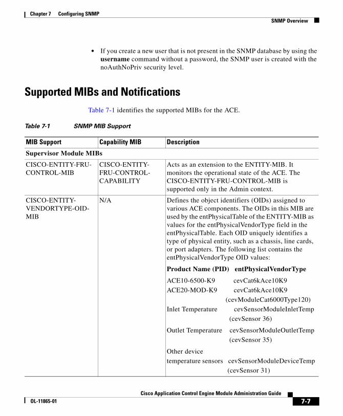
Supported MIBs and NotificationsTable 7-1 identifies the supported MIBs for the ACE.
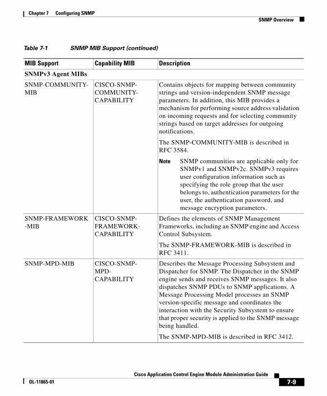
Table 7-1 SNMP MIB Support
MIB Support Capability MIB Description
Supervisor Module MIBs
CISCO-ENTITY-FRU-CONTROL-MIB
CISCO-ENTITY-FRU-CONTROL-CAPABILITY
Acts as an extension to the ENTITY-MIB. It monitors the operational state of the ACE. The CISCO-ENTITY-FRU-CONTROL-MIB is supported only in the Admin context.
CISCO-ENTITY-VENDORTYPE-OID-MIB
N/A Defines the object identifiers (OIDs) assigned to various ACE components. The OIDs in this MIB are used by the entPhysicalTable of the ENTITY-MIB as values for the entPhysicalVendorType field in the entPhysicalTable. Each OID uniquely identifies a type of physical entity, such as a chassis, line cards, or port adapters. The following list contains the entPhysicalVendorType OID values:
Product Name (PID) entPhysicalVendorType
ACE10-6500-K9 cevCat6kAce10K9
ACE20-MOD-K9 cevCat6kAce10K9
(cevModuleCat6000Type120)
Inlet Temperature cevSensorModuleInletTemp
(cevSensor 36)
Outlet Temperature cevSensorModuleOutletTemp
(cevSensor 35)
Other device
temperature sensors cevSensorModuleDeviceTemp
(cevSensor 31)
7-7Cisco Application Control Engine Module Administration Guide
OL-11865-01
Chapter 7 Configuring SNMPSNMP Overview
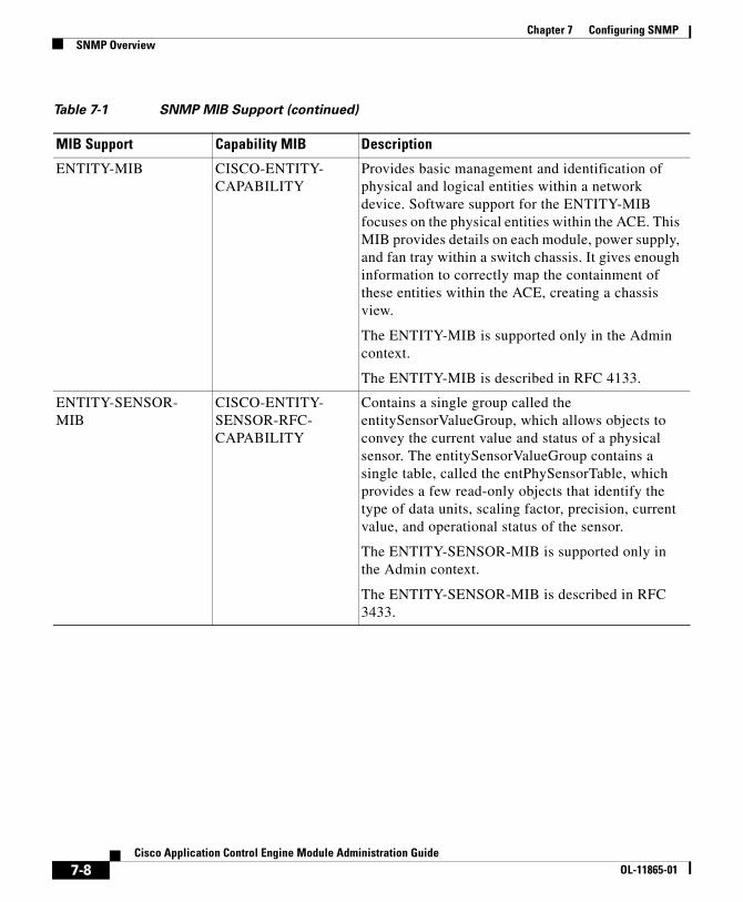
ENTITY-MIB CISCO-ENTITY-CAPABILITY
Provides basic management and identification of physical and logical entities within a network device. Software support for the ENTITY-MIB focuses on the physical entities within the ACE. This MIB provides details on each module, power supply, and fan tray within a switch chassis. It gives enough information to correctly map the containment of these entities within the ACE, creating a chassis view.
The ENTITY-MIB is supported only in the Admin context.
The ENTITY-MIB is described in RFC 4133.
ENTITY-SENSOR-MIB
CISCO-ENTITY-SENSOR-RFC-CAPABILITY
Contains a single group called the entitySensorValueGroup, which allows objects to convey the current value and status of a physical sensor. The entitySensorValueGroup contains a single table, called the entPhySensorTable, which provides a few read-only objects that identify the type of data units, scaling factor, precision, current value, and operational status of the sensor.
The ENTITY-SENSOR-MIB is supported only in the Admin context.
The ENTITY-SENSOR-MIB is described in RFC 3433.
Table 7-1 SNMP MIB Support (continued)
MIB Support Capability MIB Description
7-8Cisco Application Control Engine Module Administration Guide
OL-11865-01
Chapter 7 Configuring SNMPSNMP Overview
SNMPv3 Agent MIBs
SNMP-COMMUNITY-MIB
CISCO-SNMP-COMMUNITY-CAPABILITY
Contains objects for mapping between community strings and version-independent SNMP message parameters. In addition, this MIB provides a mechanism for performing source address validation on incoming requests and for selecting community strings based on target addresses for outgoing notifications.
The SNMP-COMMUNITY-MIB is described in RFC 3584.
Note SNMP communities are applicable only for SNMPv1 and SNMPv2c. SNMPv3 requires user configuration information such as specifying the role group that the user belongs to, authentication parameters for the user, the authentication password, and message encryption parameters.
SNMP-FRAMEWORK-MIB
CISCO-SNMP-FRAMEWORK-CAPABILITY
Defines the elements of SNMP Management Frameworks, including an SNMP engine and Access Control Subsystem.
The SNMP-FRAMEWORK-MIB is described in RFC 3411.
SNMP-MPD-MIB CISCO-SNMP-MPD-CAPABILITY
Describes the Message Processing Subsystem and Dispatcher for SNMP. The Dispatcher in the SNMP engine sends and receives SNMP messages. It also dispatches SNMP PDUs to SNMP applications. A Message Processing Model processes an SNMP version-specific message and coordinates the interaction with the Security Subsystem to ensure that proper security is applied to the SNMP message being handled.
The SNMP-MPD-MIB is described in RFC 3412.
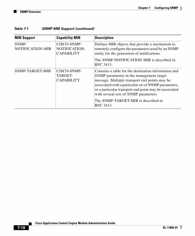
Table 7-1 SNMP MIB Support (continued)
MIB Support Capability MIB Description
7-9Cisco Application Control Engine Module Administration Guide
OL-11865-01
Chapter 7 Configuring SNMPSNMP Overview
SNMP-NOTIFICATION-MIB
CISCO-SNMP-NOTIFICATION-CAPABILITY
Defines MIB objects that provide a mechanism to remotely configure the parameters used by an SNMP entity for the generation of notifications.
The SNMP-NOTIFICATION-MIB is described in RFC 3413.
SNMP-TARGET-MIB CISCO-SNMP-TARGET-CAPABILITY
Contains a table for the destination information and SNMP parameters in the management target message. Multiple transport end points may be associated with a particular set of SNMP parameters, or a particular transport end point may be associated with several sets of SNMP parameters.
The SNMP-TARGET-MIB is described in RFC 3413.
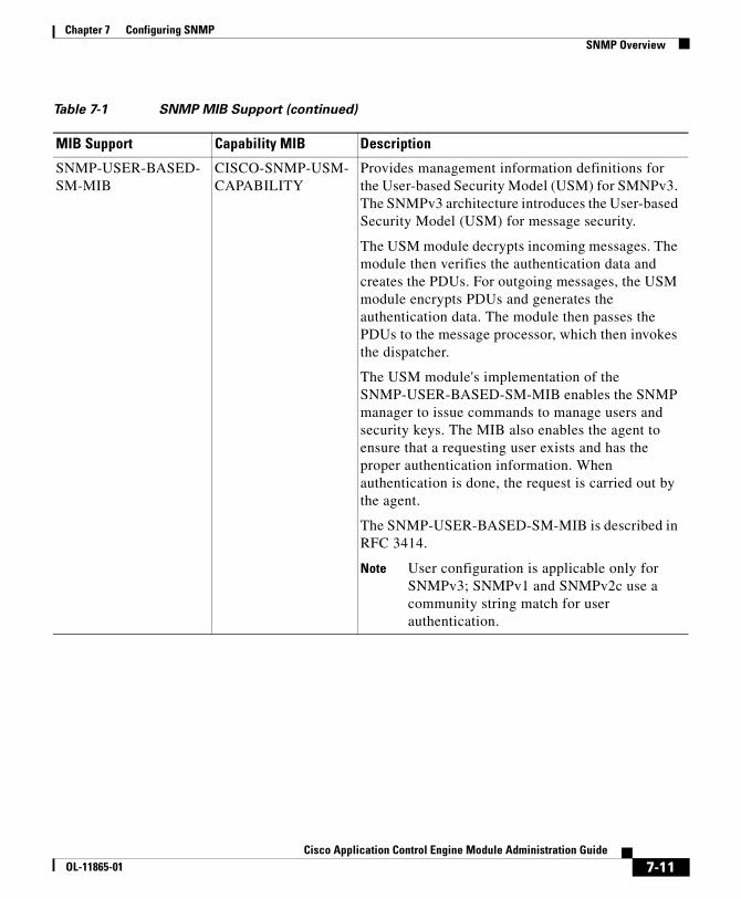
Table 7-1 SNMP MIB Support (continued)
MIB Support Capability MIB Description
7-10Cisco Application Control Engine Module Administration Guide
OL-11865-01
Chapter 7 Configuring SNMPSNMP Overview
SNMP-USER-BASED-SM-MIB
CISCO-SNMP-USM-CAPABILITY
Provides management information definitions for the User-based Security Model (USM) for SMNPv3. The SNMPv3 architecture introduces the User-based Security Model (USM) for message security.
The USM module decrypts incoming messages. The module then verifies the authentication data and creates the PDUs. For outgoing messages, the USM module encrypts PDUs and generates the authentication data. The module then passes the PDUs to the message processor, which then invokes the dispatcher.
The USM module's implementation of the SNMP-USER-BASED-SM-MIB enables the SNMP manager to issue commands to manage users and security keys. The MIB also enables the agent to ensure that a requesting user exists and has the proper authentication information. When authentication is done, the request is carried out by the agent.
The SNMP-USER-BASED-SM-MIB is described in RFC 3414.
Note User configuration is applicable only for SNMPv3; SNMPv1 and SNMPv2c use a community string match for user authentication.
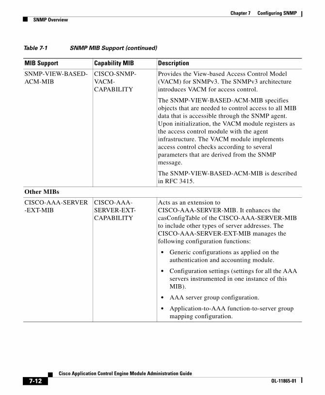
Table 7-1 SNMP MIB Support (continued)
MIB Support Capability MIB Description
7-11Cisco Application Control Engine Module Administration Guide
OL-11865-01
Chapter 7 Configuring SNMPSNMP Overview
SNMP-VIEW-BASED-ACM-MIB
CISCO-SNMP-VACM-CAPABILITY
Provides the View-based Access Control Model (VACM) for SNMPv3. The SNMPv3 architecture introduces VACM for access control.
The SNMP-VIEW-BASED-ACM-MIB specifies objects that are needed to control access to all MIB data that is accessible through the SNMP agent. Upon initialization, the VACM module registers as the access control module with the agent infrastructure. The VACM module implements access control checks according to several parameters that are derived from the SNMP message.
The SNMP-VIEW-BASED-ACM-MIB is described in RFC 3415.
Other MIBs
CISCO-AAA-SERVER-EXT-MIB
CISCO-AAA-SERVER-EXT-CAPABILITY
Acts as an extension to CISCO-AAA-SERVER-MIB. It enhances the casConfigTable of the CISCO-AAA-SERVER-MIB to include other types of server addresses. The CISCO-AAA-SERVER-EXT-MIB manages the following configuration functions:
• Generic configurations as applied on the authentication and accounting module.
• Configuration settings (settings for all the AAA servers instrumented in one instance of this MIB).
• AAA server group configuration.
• Application-to-AAA function-to-server group mapping configuration.
Table 7-1 SNMP MIB Support (continued)
MIB Support Capability MIB Description
7-12Cisco Application Control Engine Module Administration Guide
OL-11865-01
Chapter 7 Configuring SNMPSNMP Overview
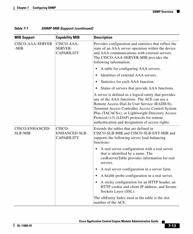
CISCO-AAA-SERVER-MIB
CISCO-AAA-SERVER-CAPABILITY
Provides configuration and statistics that reflect the state of an AAA server operation within the device and AAA communications with external servers. The CISCO-AAA-SERVER-MIB provides the following information:
• A table for configuring AAA servers.
• Identities of external AAA servers.
• Statistics for each AAA function.
• Status of servers that provide AAA functions.
A server is defined as a logical entity that provides any of the AAA functions. The ACE can use a Remote Access Dial-In User Service (RADIUS), Terminal Access Controller Access Control System Plus (TACACS+), or Lightweight Directory Access Protocol (v3) (LDAP) protocols for remote authentication and designation of access rights.
CISCO-ENHANCED-SLB-MIB
CISCO-ENHANCED-SLB-CAPABILITY
Extends the tables that are defined in CISCO-SLB-MIB and CISCO-SLB-EXT-MIB and supports the following server load-balancing functions:
• A real server configuration with a real server that is identified by a name. The cesRserverTable provides information for real servers.
• A real server configuration in a server farm.
• A health probe configuration in a real server.
• A sticky configuration for an HTTP header, an HTTP cookie and client IP address, and Secure Sockets Layer (SSL).
The slbEntity Index used in the table is the slot number of the ACE.
Table 7-1 SNMP MIB Support (continued)
MIB Support Capability MIB Description
7-13Cisco Application Control Engine Module Administration Guide
OL-11865-01
Chapter 7 Configuring SNMPSNMP Overview
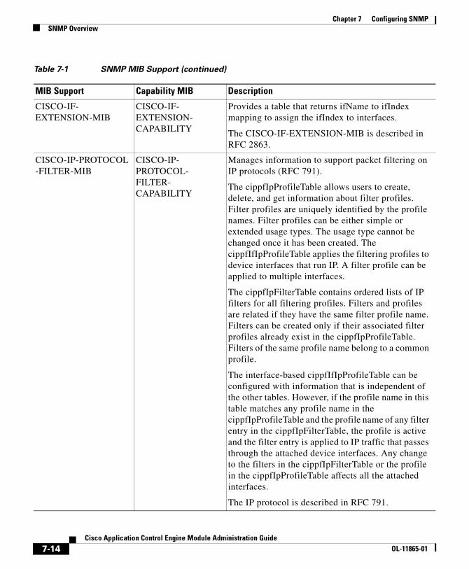
CISCO-IF-EXTENSION-MIB
CISCO-IF-EXTENSION-CAPABILITY
Provides a table that returns ifName to ifIndex mapping to assign the ifIndex to interfaces.
The CISCO-IF-EXTENSION-MIB is described in RFC 2863.
CISCO-IP-PROTOCOL-FILTER-MIB
CISCO-IP-PROTOCOL-FILTER-CAPABILITY
Manages information to support packet filtering on IP protocols (RFC 791).
The cippfIpProfileTable allows users to create, delete, and get information about filter profiles. Filter profiles are uniquely identified by the profile names. Filter profiles can be either simple or extended usage types. The usage type cannot be changed once it has been created. The cippfIfIpProfileTable applies the filtering profiles to device interfaces that run IP. A filter profile can be applied to multiple interfaces.
The cippfIpFilterTable contains ordered lists of IP filters for all filtering profiles. Filters and profiles are related if they have the same filter profile name. Filters can be created only if their associated filter profiles already exist in the cippfIpProfileTable. Filters of the same profile name belong to a common profile.
The interface-based cippfIfIpProfileTable can be configured with information that is independent of the other tables. However, if the profile name in this table matches any profile name in the cippfIpProfileTable and the profile name of any filter entry in the cippfIpFilterTable, the profile is active and the filter entry is applied to IP traffic that passes through the attached device interfaces. Any change to the filters in the cippfIpFilterTable or the profile in the cippfIpProfileTable affects all the attached interfaces.
The IP protocol is described in RFC 791.
Table 7-1 SNMP MIB Support (continued)
MIB Support Capability MIB Description
7-14Cisco Application Control Engine Module Administration Guide
OL-11865-01
Chapter 7 Configuring SNMPSNMP Overview
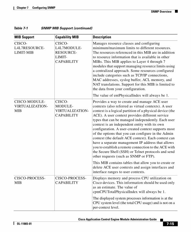
CISCO-L4L7RESOURCE-LIMIT-MIB
CISCO-L4L7MODULE-RESOURCE-LIMIT-CAPABILITY
Manages resource classes and configuring minimum/maximum limits to different resources. The resources referenced in this MIB are in addition to resource information that is available in other MIBs. This MIB applies to Layer 4 through 7 modules that support managing resource limits using a centralized approach. Some resources configured include categories such as TCP/IP connections, MAC addresses, syslog buffer, ACL memory, and NAT translations. Support for this MIB is limited to the data from your configuration.
The value of entPhysicalIndex will always be 1.
CISCO-MODULE-VIRTUALIZATION-MIB
CISCO-MODULE-VIRTUALIZATION-CAPABILITY
Provides a way to create and manage ACE user contexts (also referred as virtual contexts). A user context is a logical partition of a physical device (the ACE). A user context provides different service types that can be managed independently. Each user context is an independent entity with its own configuration. A user-created context supports most of the options that you can configure in the Admin context (the default ACE context). Each context can have a separate management IP address that allows you to establish a remote connection to the ACE with the Secure Shell (SSH) or Telnet protocols and send other requests (such as SNMP or FTP).
This MIB contains tables that allow you to create or delete ACE user contexts and assign interfaces and interface ranges to user contexts.
CISCO-PROCESS-MIB
CISCO-PROCESS-CAPABILITY
Displays memory and process CPU utilization on Cisco devices. This information should be used only as an estimate. The value of cpmCPUTotalPhysicalIndex will always be 1.
The displayed system processes information is at the CPU system level (the total CPU usage) and is not on a per-context level.
Table 7-1 SNMP MIB Support (continued)
MIB Support Capability MIB Description
7-15Cisco Application Control Engine Module Administration Guide
OL-11865-01
Chapter 7 Configuring SNMPSNMP Overview
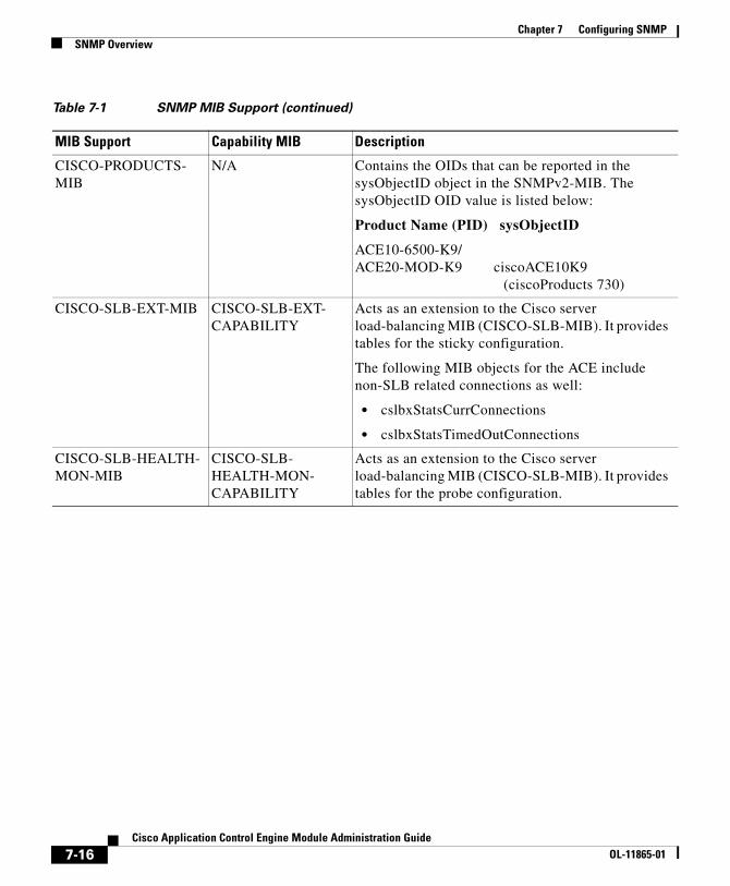
CISCO-PRODUCTS-MIB
N/A Contains the OIDs that can be reported in the sysObjectID object in the SNMPv2-MIB. The sysObjectID OID value is listed below:
Product Name (PID) sysObjectID
ACE10-6500-K9/ ACE20-MOD-K9 ciscoACE10K9
(ciscoProducts 730)
CISCO-SLB-EXT-MIB CISCO-SLB-EXT-CAPABILITY
Acts as an extension to the Cisco server load-balancing MIB (CISCO-SLB-MIB). It provides tables for the sticky configuration.
The following MIB objects for the ACE include non-SLB related connections as well:
• cslbxStatsCurrConnections
• cslbxStatsTimedOutConnections
CISCO-SLB-HEALTH-MON-MIB
CISCO-SLB-HEALTH-MON-CAPABILITY
Acts as an extension to the Cisco server load-balancing MIB (CISCO-SLB-MIB). It provides tables for the probe configuration.
Table 7-1 SNMP MIB Support (continued)
MIB Support Capability MIB Description
7-16Cisco Application Control Engine Module Administration Guide
OL-11865-01
Chapter 7 Configuring SNMPSNMP Overview
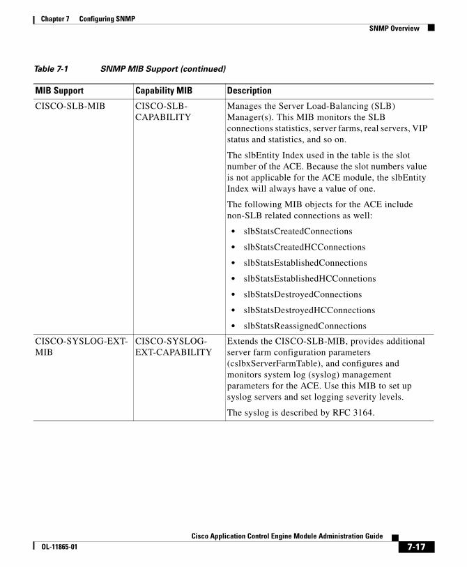
CISCO-SLB-MIB CISCO-SLB-CAPABILITY
Manages the Server Load-Balancing (SLB) Manager(s). This MIB monitors the SLB connections statistics, server farms, real servers, VIP status and statistics, and so on.
The slbEntity Index used in the table is the slot number of the ACE. Because the slot numbers value is not applicable for the ACE module, the slbEntity Index will always have a value of one.
The following MIB objects for the ACE include non-SLB related connections as well:
• slbStatsCreatedConnections
• slbStatsCreatedHCConnections
• slbStatsEstablishedConnections
• slbStatsEstablishedHCConnetions
• slbStatsDestroyedConnections
• slbStatsDestroyedHCConnections
• slbStatsReassignedConnections
CISCO-SYSLOG-EXT-MIB
CISCO-SYSLOG-EXT-CAPABILITY
Extends the CISCO-SLB-MIB, provides additional server farm configuration parameters (cslbxServerFarmTable), and configures and monitors system log (syslog) management parameters for the ACE. Use this MIB to set up syslog servers and set logging severity levels.
The syslog is described by RFC 3164.
Table 7-1 SNMP MIB Support (continued)
MIB Support Capability MIB Description
7-17Cisco Application Control Engine Module Administration Guide
OL-11865-01
Chapter 7 Configuring SNMPSNMP Overview
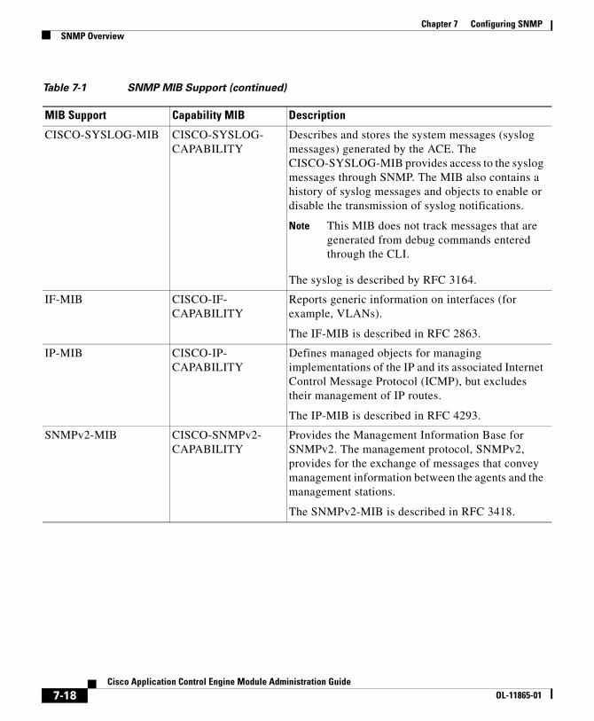
CISCO-SYSLOG-MIB CISCO-SYSLOG-CAPABILITY
Describes and stores the system messages (syslog messages) generated by the ACE. The CISCO-SYSLOG-MIB provides access to the syslog messages through SNMP. The MIB also contains a history of syslog messages and objects to enable or disable the transmission of syslog notifications.
Note This MIB does not track messages that are generated from debug commands entered through the CLI.
The syslog is described by RFC 3164.
IF-MIB CISCO-IF-CAPABILITY
Reports generic information on interfaces (for example, VLANs).
The IF-MIB is described in RFC 2863.
IP-MIB CISCO-IP-CAPABILITY
Defines managed objects for managing implementations of the IP and its associated Internet Control Message Protocol (ICMP), but excludes their management of IP routes.
The IP-MIB is described in RFC 4293.
SNMPv2-MIB CISCO-SNMPv2-CAPABILITY
Provides the Management Information Base for SNMPv2. The management protocol, SNMPv2, provides for the exchange of messages that convey management information between the agents and the management stations.
The SNMPv2-MIB is described in RFC 3418.
Table 7-1 SNMP MIB Support (continued)
MIB Support Capability MIB Description
7-18Cisco Application Control Engine Module Administration Guide
OL-11865-01
Chapter 7 Configuring SNMPSNMP Overview
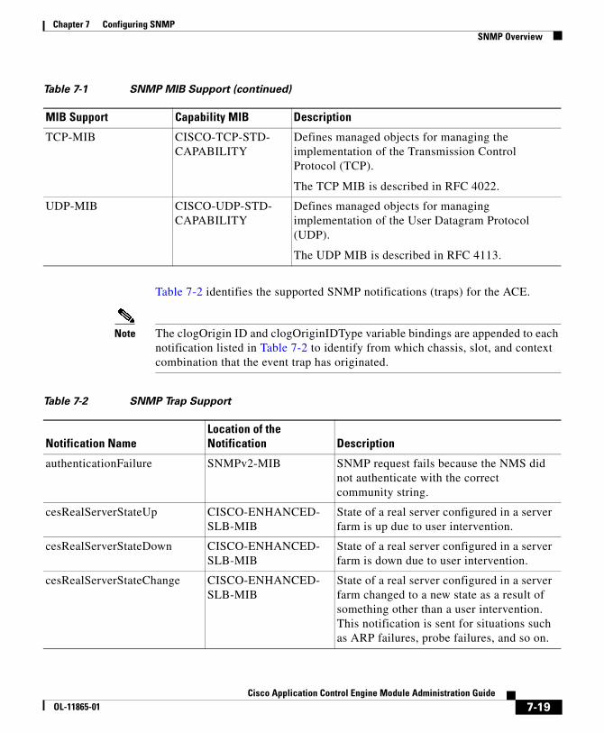
Table 7-2 identifies the supported SNMP notifications (traps) for the ACE.
Note The clogOrigin ID and clogOriginIDType variable bindings are appended to each notification listed in Table 7-2 to identify from which chassis, slot, and context combination that the event trap has originated.
TCP-MIB CISCO-TCP-STD-CAPABILITY
Defines managed objects for managing the implementation of the Transmission Control Protocol (TCP).
The TCP MIB is described in RFC 4022.
UDP-MIB CISCO-UDP-STD-CAPABILITY
Defines managed objects for managing implementation of the User Datagram Protocol (UDP).
The UDP MIB is described in RFC 4113.
Table 7-1 SNMP MIB Support (continued)
MIB Support Capability MIB Description
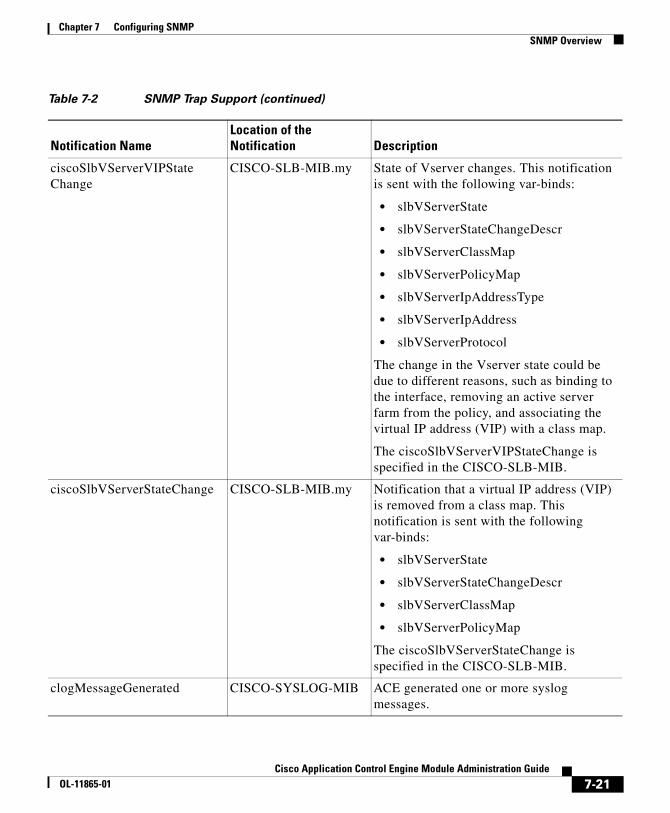
Table 7-2 SNMP Trap Support
Notification NameLocation of the Notification Description
authenticationFailure SNMPv2-MIB SNMP request fails because the NMS did not authenticate with the correct community string.
cesRealServerStateUp CISCO-ENHANCED-SLB-MIB
State of a real server configured in a server farm is up due to user intervention.
cesRealServerStateDown CISCO-ENHANCED-SLB-MIB
State of a real server configured in a server farm is down due to user intervention.
cesRealServerStateChange CISCO-ENHANCED-SLB-MIB
State of a real server configured in a server farm changed to a new state as a result of something other than a user intervention. This notification is sent for situations such as ARP failures, probe failures, and so on.
7-19Cisco Application Control Engine Module Administration Guide
OL-11865-01
Chapter 7 Configuring SNMPSNMP Overview
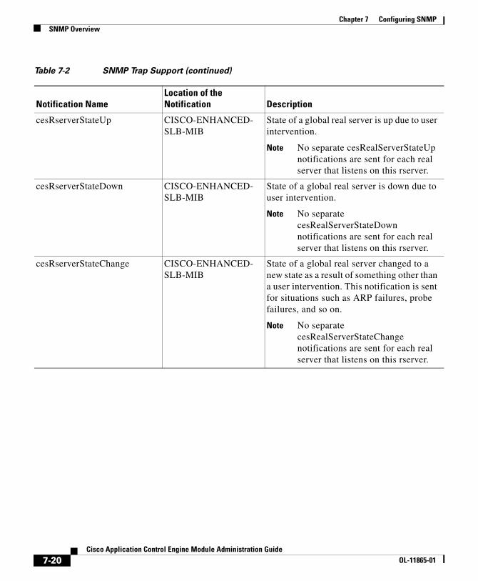
cesRserverStateUp CISCO-ENHANCED-SLB-MIB
State of a global real server is up due to user intervention.
Note No separate cesRealServerStateUp notifications are sent for each real server that listens on this rserver.
cesRserverStateDown CISCO-ENHANCED-SLB-MIB
State of a global real server is down due to user intervention.
Note No separate cesRealServerStateDown notifications are sent for each real server that listens on this rserver.
cesRserverStateChange CISCO-ENHANCED-SLB-MIB
State of a global real server changed to a new state as a result of something other than a user intervention. This notification is sent for situations such as ARP failures, probe failures, and so on.
Note No separate cesRealServerStateChange notifications are sent for each real server that listens on this rserver.
Table 7-2 SNMP Trap Support (continued)
Notification NameLocation of the Notification Description
7-20Cisco Application Control Engine Module Administration Guide
OL-11865-01
Chapter 7 Configuring SNMPSNMP Overview
ciscoSlbVServerVIPStateChange
CISCO-SLB-MIB.my State of Vserver changes. This notification is sent with the following var-binds:
• slbVServerState
• slbVServerStateChangeDescr
• slbVServerClassMap
• slbVServerPolicyMap
• slbVServerIpAddressType
• slbVServerIpAddress
• slbVServerProtocol
The change in the Vserver state could be due to different reasons, such as binding to the interface, removing an active server farm from the policy, and associating the virtual IP address (VIP) with a class map.
The ciscoSlbVServerVIPStateChange is specified in the CISCO-SLB-MIB.
ciscoSlbVServerStateChange CISCO-SLB-MIB.my Notification that a virtual IP address (VIP) is removed from a class map. This notification is sent with the following var-binds:
• slbVServerState
• slbVServerStateChangeDescr
• slbVServerClassMap
• slbVServerPolicyMap
The ciscoSlbVServerStateChange is specified in the CISCO-SLB-MIB.
clogMessageGenerated CISCO-SYSLOG-MIB ACE generated one or more syslog messages.
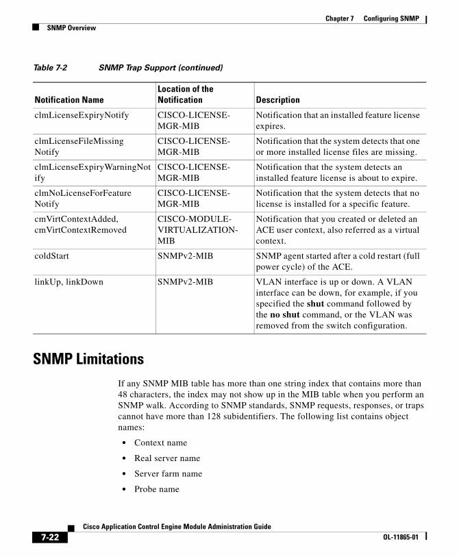
Table 7-2 SNMP Trap Support (continued)
Notification NameLocation of the Notification Description
7-21Cisco Application Control Engine Module Administration Guide
OL-11865-01
Chapter 7 Configuring SNMPSNMP Overview
SNMP LimitationsIf any SNMP MIB table has more than one string index that contains more than 48 characters, the index may not show up in the MIB table when you perform an SNMP walk. According to SNMP standards, SNMP requests, responses, or traps cannot have more than 128 subidentifiers. The following list contains object names:
• Context name
• Real server name
• Server farm name
• Probe name
clmLicenseExpiryNotify CISCO-LICENSE-MGR-MIB
Notification that an installed feature license expires.
clmLicenseFileMissingNotify
CISCO-LICENSE-MGR-MIB
Notification that the system detects that one or more installed license files are missing.
clmLicenseExpiryWarningNotify
CISCO-LICENSE-MGR-MIB
Notification that the system detects an installed feature license is about to expire.
clmNoLicenseForFeatureNotify
CISCO-LICENSE-MGR-MIB
Notification that the system detects that no license is installed for a specific feature.
cmVirtContextAdded, cmVirtContextRemoved
CISCO-MODULE-VIRTUALIZATION-MIB
Notification that you created or deleted an ACE user context, also referred as a virtual context.
coldStart SNMPv2-MIB SNMP agent started after a cold restart (full power cycle) of the ACE.
linkUp, linkDown SNMPv2-MIB VLAN interface is up or down. A VLAN interface can be down, for example, if you specified the shut command followed by the no shut command, or the VLAN was removed from the switch configuration.
Table 7-2 SNMP Trap Support (continued)
Notification NameLocation of the Notification Description
7-22Cisco Application Control Engine Module Administration Guide
OL-11865-01
Chapter 7 Configuring SNMPSNMP Overview
• HTTP header name
• ACL name
• Class map name
• Policy map name
• Resource class name
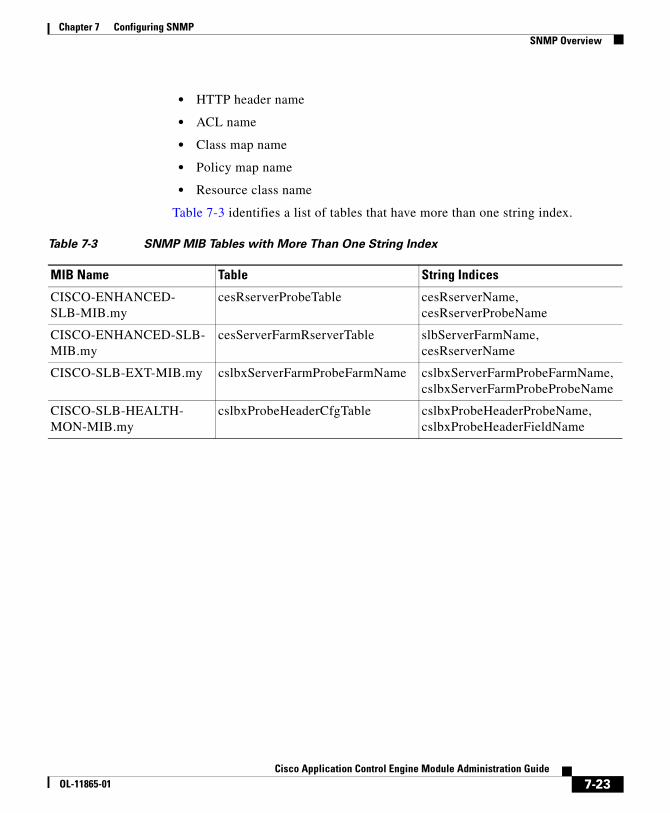
Table 7-3 identifies a list of tables that have more than one string index.
Table 7-3 SNMP MIB Tables with More Than One String Index
MIB Name Table String Indices
CISCO-ENHANCED- SLB-MIB.my
cesRserverProbeTable cesRserverName,cesRserverProbeName
CISCO-ENHANCED-SLB-MIB.my
cesServerFarmRserverTable slbServerFarmName, cesRserverName
CISCO-SLB-EXT-MIB.my cslbxServerFarmProbeFarmName cslbxServerFarmProbeFarmName,cslbxServerFarmProbeProbeName
CISCO-SLB-HEALTH-MON-MIB.my
cslbxProbeHeaderCfgTable cslbxProbeHeaderProbeName,cslbxProbeHeaderFieldName
7-23Cisco Application Control Engine Module Administration Guide
OL-11865-01
Chapter 7 Configuring SNMPSNMP Configuration Quick Start
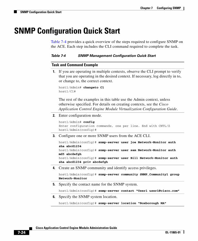
SNMP Configuration Quick StartTable 7-4 provides a quick overview of the steps required to configure SNMP on the ACE. Each step includes the CLI command required to complete the task.
Table 7-4 SNMP Management Configuration Quick Start
Task and Command Example
1. If you are operating in multiple contexts, observe the CLI prompt to verify that you are operating in the desired context. If necessary, log directly in to, or change to, the correct context.
host1/Admin# changeto C1host1/C1#
The rest of the examples in this table use the Admin context, unless otherwise specified. For details on creating contexts, see the Cisco Application Control Engine Module Virtualization Configuration Guide.
2. Enter configuration mode.
host1/Admin# configEnter configuration commands, one per line. End with CNTL/Zhost1/Admin(config)#
3. Configure one or more SNMP users from the ACE CLI.
host1/Admin(config)# snmp-server user joe Network-Monitor auth sha abcd1234host1/Admin(config)# snmp-server user sam Network-Monitor auth md5 abcdefghhost1/Admin(config)# snmp-server user Bill Network-Monitor auth sha abcd1234 priv abcdefgh
4. Create an SNMP community and identify access privileges.
host1/Admin(config)# snmp-server community SNMP_Community1 group Network-Monitor
5. Specify the contact name for the SNMP system.
host1/Admin(config)# snmp-server contact “User1 [email protected]”
6. Specify the SNMP system location.
host1/Admin(config)# snmp-server location “Boxborough MA”
7-24Cisco Application Control Engine Module Administration Guide
OL-11865-01
Chapter 7 Configuring SNMPSNMP Configuration Quick Start
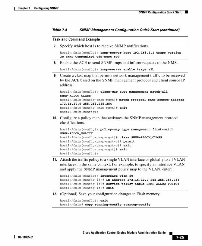
7. Specify which host is to receive SNMP notifications.
host1/Admin(config)# snmp-server host 192.168.1.1 traps version 2c SNMP_Community1 udp-port 500
8. Enable the ACE to send SNMP traps and inform requests to the NMS.
host1/Admin(config)# snmp-server enable traps slb
9. Create a class map that permits network management traffic to be received by the ACE based on the SNMP management protocol and client source IP address.
host1/Admin(config)# class-map type management match-all SNMP-ALLOW_CLASShost1/Admin(config-cmap-mgmt)# match protocol snmp source-address 172.16.10.0 255.255.255.254host1/Admin(config-cmap-mgmt)# exithost1/Admin(config)#
10. Configure a policy map that activates the SNMP management protocol classifications.
host1/Admin(config)# policy-map type management first-match SNMP-ALLOW_POLICYhost1/Admin(config-pmap-mgmt)# class SNMP-ALLOW_CLASShost1/Admin(config-pmap-mgmt-c)# permithost1/Admin(config-pmap-mgmt-c)# exithost1/Admin(config-pmap-mgmt)# exithost1/Admin(config)#
11. Attach the traffic policy to a single VLAN interface or globally to all VLAN interfaces in the same context. For example, to specify an interface VLAN and apply the SNMP management policy map to the VLAN, enter:
host1/Admin(config)# interface vlan 50host1/Admin(config-if)# ip address 172.16.10.0 255.255.255.254host1/Admin(config-if)# service-policy input SNMP-ALLOW_POLICYhost1/Admin(config-if)# exit
12. (Optional) Save your configuration changes to Flash memory.
host1/Admin(config)# exithost1/Admin# copy running-config startup-config
Table 7-4 SNMP Management Configuration Quick Start (continued)
Task and Command Example
7-25Cisco Application Control Engine Module Administration Guide
OL-11865-01
Chapter 7 Configuring SNMPConfiguring SNMP Users
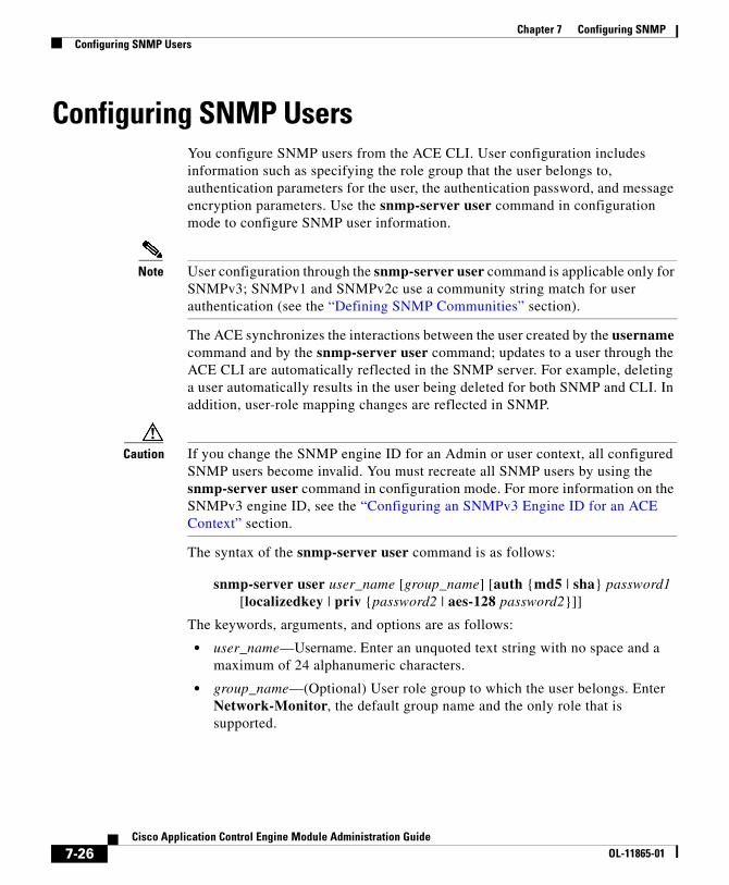
Configuring SNMP UsersYou configure SNMP users from the ACE CLI. User configuration includes information such as specifying the role group that the user belongs to, authentication parameters for the user, the authentication password, and message encryption parameters. Use the snmp-server user command in configuration mode to configure SNMP user information.
Note User configuration through the snmp-server user command is applicable only for SNMPv3; SNMPv1 and SNMPv2c use a community string match for user authentication (see the “Defining SNMP Communities” section).
The ACE synchronizes the interactions between the user created by the username command and by the snmp-server user command; updates to a user through the ACE CLI are automatically reflected in the SNMP server. For example, deleting a user automatically results in the user being deleted for both SNMP and CLI. In addition, user-role mapping changes are reflected in SNMP.
Caution If you change the SNMP engine ID for an Admin or user context, all configured SNMP users become invalid. You must recreate all SNMP users by using the snmp-server user command in configuration mode. For more information on the SNMPv3 engine ID, see the “Configuring an SNMPv3 Engine ID for an ACE Context” section.
The syntax of the snmp-server user command is as follows:
snmp-server user user_name [group_name] [auth {md5 | sha} password1 [localizedkey | priv {password2 | aes-128 password2}]]
The keywords, arguments, and options are as follows:
• user_name—Username. Enter an unquoted text string with no space and a maximum of 24 alphanumeric characters.
• group_name—(Optional) User role group to which the user belongs. Enter Network-Monitor, the default group name and the only role that is supported.
7-26Cisco Application Control Engine Module Administration Guide
OL-11865-01
Chapter 7 Configuring SNMPConfiguring SNMP Users
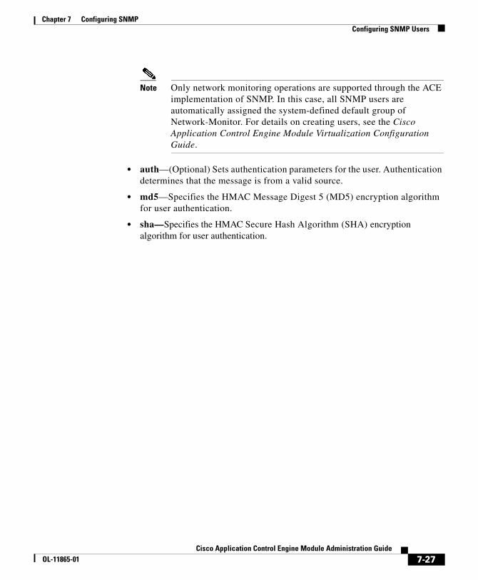
Note Only network monitoring operations are supported through the ACE implementation of SNMP. In this case, all SNMP users are automatically assigned the system-defined default group of Network-Monitor. For details on creating users, see the Cisco Application Control Engine Module Virtualization Configuration Guide.
• auth—(Optional) Sets authentication parameters for the user. Authentication determines that the message is from a valid source.
• md5—Specifies the HMAC Message Digest 5 (MD5) encryption algorithm for user authentication.
• sha—Specifies the HMAC Secure Hash Algorithm (SHA) encryption algorithm for user authentication.
7-27Cisco Application Control Engine Module Administration Guide
OL-11865-01
Chapter 7 Configuring SNMPConfiguring SNMP Users
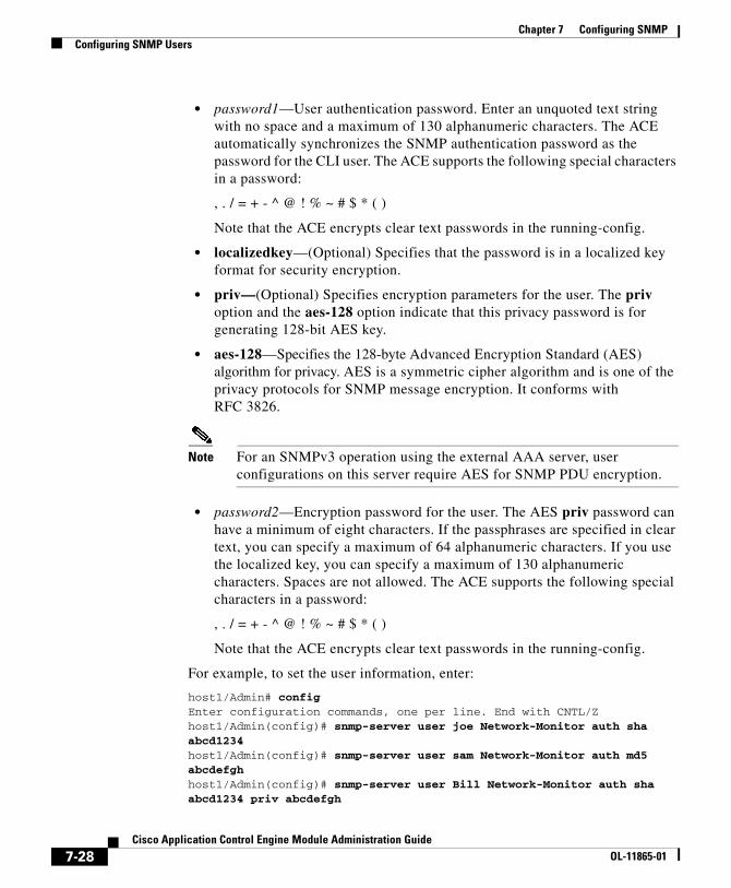
• password1—User authentication password. Enter an unquoted text string with no space and a maximum of 130 alphanumeric characters. The ACE automatically synchronizes the SNMP authentication password as the password for the CLI user. The ACE supports the following special characters in a password:
, . / = + - ^ @ ! % ~ # $ * ( )
Note that the ACE encrypts clear text passwords in the running-config.
• localizedkey—(Optional) Specifies that the password is in a localized key format for security encryption.
• priv—(Optional) Specifies encryption parameters for the user. The priv option and the aes-128 option indicate that this privacy password is for generating 128-bit AES key.
• aes-128—Specifies the 128-byte Advanced Encryption Standard (AES) algorithm for privacy. AES is a symmetric cipher algorithm and is one of the privacy protocols for SNMP message encryption. It conforms with RFC 3826.
Note For an SNMPv3 operation using the external AAA server, user configurations on this server require AES for SNMP PDU encryption.
• password2—Encryption password for the user. The AES priv password can have a minimum of eight characters. If the passphrases are specified in clear text, you can specify a maximum of 64 alphanumeric characters. If you use the localized key, you can specify a maximum of 130 alphanumeric characters. Spaces are not allowed. The ACE supports the following special characters in a password:
, . / = + - ^ @ ! % ~ # $ * ( )
Note that the ACE encrypts clear text passwords in the running-config.
For example, to set the user information, enter:
host1/Admin# configEnter configuration commands, one per line. End with CNTL/Zhost1/Admin(config)# snmp-server user joe Network-Monitor auth sha abcd1234host1/Admin(config)# snmp-server user sam Network-Monitor auth md5 abcdefghhost1/Admin(config)# snmp-server user Bill Network-Monitor auth sha abcd1234 priv abcdefgh
7-28Cisco Application Control Engine Module Administration Guide
OL-11865-01
Chapter 7 Configuring SNMPDefining SNMP Communities
To disable the SNMP user configuration or to remove an SNMP user, use the no form of the command. For example, enter:
host1/Admin(config)# no snmp-server user Bill Network-Monitor auth sha abcd1234 priv abcdefgh
Defining SNMP CommunitiesEach SNMP device or member is part of a community. An SNMP community determines the access rights for each SNMP device. SNMP uses communities to establish trust between managers and agents.
You supply a name to the community. After that, all SNMP devices assigned to that community as members have the same access rights (as described in RFC 2576). The ACE allows read-only access to the MIB tree for devices included in this community. The read-only community string allows a user to read data values, but prevents that user from modifying modify the data.
To create or modify SNMP community names and access privileges, use the snmp-server community command in configuration mode.
Note SNMP communities are applicable only for SNMPv1 and SNMPv2c. SNMPv3 requires user configuration information such as specifying the role group that the user belongs to, authentication parameters for the user, authentication password, and message encryption parameters (see the “Configuring SNMP Users” section).
Caution If you change the SNMP engine ID for an Admin or user context, all configured SNMP communities are deleted. You must recreate all SNMP communities by using the snmp-server community command in configuration mode. For more information on the SNMPv3 engine ID, see the “Configuring an SNMPv3 Engine ID for an ACE Context” section.
The syntax of this command is as follows:
snmp-server community community_name [group group_name | ro]
The keywords, arguments, and options are as follows:
7-29Cisco Application Control Engine Module Administration Guide
OL-11865-01
Chapter 7 Configuring SNMPConfiguring an SNMP Contact
• community_name—SNMP community name for this system. Enter an unquoted text string with no space and a maximum of 32 alphanumeric characters.
• group group_name—(Optional) Identifies the role group to which the user belongs. Enter an unquoted text string with no space and a maximum of 32 alphanumeric characters.
Note Only network monitoring operations are supported through the ACE implementation of SNMP. In this case, all SNMP users are automatically assigned the system-defined default group of Network-Monitor. For details on creating users, see the Cisco Application Control Engine Module Virtualization Configuration Guide.
• ro—(Optional) Allows read-only access for this community.
For example, to specify an SNMP community called SNMP_Community1, a member of the Network-Monitor group, with read-only access privileges for the community, enter:
host1/Admin(config)# snmp-server community SNMP_Community1 group Network-Monitor
To remove an SNMP community, enter:
host1/Admin(config)# no snmp-server community SNMP_Community1 group Network-Monitor
Configuring an SNMP Contact To specify the contact information for the SNMP system, use the snmp-server contact command in configuration mode. You can specify information for only one contact name. The syntax of this command is as follows:
snmp-server contact contact_information
7-30Cisco Application Control Engine Module Administration Guide
OL-11865-01
Chapter 7 Configuring SNMPConfiguring an SNMP Location
Enter the contact_information argument as a text string with a maximum of 240 alphanumeric characters, including spaces. If the string contains more than one word, enclose the string in quotation marks (“ ”). You can include information on how to contact the person; for example, you can provide a phone number or an e-mail address.
For example, to specify SNMP system contact information, enter:
host1/Admin(config-context)# snmp-server contact “User1 [email protected]”
To remove the specified SNMP contact name, enter:
host1/Admin(config)# no snmp-server contact
Configuring an SNMP LocationTo specify the SNMP system location, use the snmp-server location command in configuration mode. You can specify only one location. The syntax of this command is as follows:
snmp-server location location
Enter the location as the physical location of the system. Enter a text string with a maximum of 240 alphanumeric characters, including spaces. If the string contains more than one word, enclose the string in quotation marks (“ ”).
For example, to specify SNMP system location information, enter:
host1/Admin(config)# snmp-server location “Boxborough MA”
To remove the specified SNMP system location information, enter:
host1/Admin(config)# no snmp-server location
Configuring SNMP NotificationsYou can configure the ACE to send traps or inform requests as notifications to an SNMP manager when a particular event occurs. In some instances, traps are unreliable because the receiver does not send any acknowledgment when it receives a trap. The sender cannot determine if the trap was received. However, an SNMP manager that receives inform requests acknowledges the message with
7-31Cisco Application Control Engine Module Administration Guide
OL-11865-01
Chapter 7 Configuring SNMPConfiguring SNMP Notifications
an SNMP Response PDU. If the sender never receives a Response, the inform request is normally retransmitted. Inform requests are more likely to reach their intended destination.
Note Use the SNMP-TARGET-MIB to obtain more information on the destinations to which notifications are to be sent either as traps or as SNMP inform requests. See the “Supported MIBs and Notifications” section for details.
This section contains the following topics:
• Configuring SNMP Notification Hosts
• Enabling SNMP Notifications
• Enabling the IETF Standard for SNMP linkUp and linkDown Traps
Configuring SNMP Notification HostsUse the snmp-server host command in configuration mode to specify which host receives SNMP notifications. In order to send notifications, you must configure at least one snmp-server host command. The ACE supports a maximum of 10 SNMP hosts per context.
The syntax of this command is as follows:
snmp-server host host_address {community-string_username | informs | traps | version {1{udp-port} | 2c {udp-port} | 3 [auth | noauth | priv]}}
The keywords, arguments, and options are as follows:
• host_address—IP address of the host (the targeted recipient). Enter the address in dotted-decimal IP notation (for example, 192.168.11.1).
• community-string_username—SNMP community string or username with the notification operation. Enter an unquoted text string with no space and a maximum of 32 alphanumeric characters.
• informs—Sends SNMP inform requests to the identified host, which allows for manager-to-manager communication. Inform requests can be useful when the need arises for more than one NMS in the network.
7-32Cisco Application Control Engine Module Administration Guide
OL-11865-01
Chapter 7 Configuring SNMPConfiguring SNMP Notifications
• traps—Sends SNMP traps to the identified host. A trap is the method for an agent to tell the NMS that a problem has occurred. The trap originates from the agent and is sent to the trap destination, as configured within the agent itself. Typically the trap destination is the IP address of the NMS.
• version—Specifies the version of SNMP used to send the traps. SNMPv3 is the most secure model because it allows packet encryption with the priv keyword.
• 1—Specifies SNMPv1. This option is not available for use with SNMP inform requests. SNMPv1 has one optional keyword (udp-port) that specifies the UDP port of the host to use. The default is 162.
• 2c—Specifies SNMPv2C. SNMPv2C has one optional keyword (udp-port) that specifies the UDP port of the host to use. The default is 162.
• 3—Specifies SNMPv3. SNMPv3 has three optional keywords (auth, no auth, or priv).
• auth—(Optional) Enables Message Digest 5 (MD5) and Secure Hash Algorithm (SHA) packet authentication.
• noauth—(Optional) Specifies the noAuthNoPriv security level.
• priv—(Optional) Enables Data Encryption Standard (DES) packet encryption (privacy).
For example, to specify the recipient of an SNMP notification, enter:
host1/Admin(config)# snmp-server host 192.168.1.1 traps version 2c SNMP_Community1 udp-port 500
To remove the specified host, use the no form of the command. For example, enter:
host1/Admin(config)# no snmp-server host 192.168.1.1 traps version 2c SNMP_Community1 udp-port 500
7-33Cisco Application Control Engine Module Administration Guide
OL-11865-01
Chapter 7 Configuring SNMPConfiguring SNMP Notifications
Enabling SNMP NotificationsNotification traps and inform requests are system alerts that the ACE generates when certain events occur. SNMP notifications can be sent to the NMS as traps or inform requests. By default, no notification is defined or issued. To enable the ACE to send SNMP traps and informs to the NMS, use the snmp-server enable traps command in configuration mode. This command enables both traps and inform requests for the specified notification types.
To configure the ACE to send the SNMP notifications, specify at least one snmp-server enable traps command. To enable multiple types of notifications, you must enter a separate snmp-server enable traps command for each notification type and notification option. If you enter the command without any keywords, the ACE enables all notification types and traps.
The snmp-server enable traps command is used with the snmp-server host command (see the “Configuring SNMP Notification Hosts” section). The snmp-server host command specifies which host receives the SNMP notifications. To send notifications, you must configure at least one SNMP server host.
Note The notification types used in the snmp-server enable traps command all have an associated MIB object that globally enables or disables them. However, not all of the notification types available in the snmp-server host command have notificationEnable MIB objects, so some of the notification types cannot be controlled by using the snmp-server enable command.
The syntax of this command is as follows:
snmp-server enable traps [notification_type] [notification_option]
The keywords, arguments, and options are as follows:
• notification_type—(Optional) Type of notification to enable. If no type is specified, the ACE sends all notifications. Specify one of the following keywords as the notification_type:
– license—Sends SNMP license manager notifications. This keyword appears only in the Admin context.
– slb—Sends server load-balancing notifications. When you specify the slb keyword, you can specify a notification_option value.
7-34Cisco Application Control Engine Module Administration Guide
OL-11865-01
Chapter 7 Configuring SNMPConfiguring SNMP Notifications
– snmp—Sends SNMP notifications. When you specify the snmp keyword, you can specify a notification_option value.
– syslog—Sends error message notifications (Cisco Syslog MIB). Specify the level of messages to be sent with the logging history level command.
Note To enable system messages to be sent as traps to the NMS, you can specify the logging history command. You must also enable syslog traps by using the snmp-server enable traps command. See the Cisco Application Control Engine Module System Message Guide for details.
– virtual-context—Sends virtual context (ACE user context) change notifications. This keyword appears only in the Admin context.
• notification_option—(Optional) One of the following SNMP notifications:
– When you specify the snmp keyword, specify the authentication, coldstart, linkdown, or linkup keyword to enable SNMP notifications. This selection generates a notification if the community string provided in the SNMP request is incorrect, or when a VLAN interface is either up or down. The coldstart keyword appears only in the Admin context.
– When you specify the slb keyword, specify the real or vserver keyword to enable server load-balancing notifications. This selection generates a notification if the following state change occurs:
The real server changes state (up or down) due to user intervention, ARP failures, or probe failures.
The virtual server changes state (up or down). The virtual server represents the servers behind the content switch in the ACE to the outside world and consists of the following attributes: the destination address (can be a range of IP addresses), the protocol, the destination port, or the incoming VLAN.
For example, to enable the ACE to send server load-balancing traps to the host at IP address 192.168.1.1 using the community string public, enter:
host1/Admin(config)# snmp-server host 192.168.1.1host1/Admin(config)# snmp-server community SNMP_Community1 group Network-Monitorhost1/Admin(config)# snmp-server enable traps slb real
7-35Cisco Application Control Engine Module Administration Guide
OL-11865-01
Chapter 7 Configuring SNMPConfiguring SNMP Notifications
To disable SNMP server notifications, use the no form of the command. For example, enter:
host1/Admin(config)# no snmp-server enable traps slb real
Enabling the IETF Standard for SNMP linkUp and linkDown TrapsBy default, the ACE sends the Cisco implementation of linkUp and linkDown traps to the NMS. The ACE sends the Cisco Systems IF-MIB variable bindings, which consists of ifIndex, ifAdminStatus, ifOperStatus, ifName, ifType, clogOriginID, and clogOriginIDType. You can configure the ACE to send the Internet Engineering Task Force (IETF) standards-based implementation for linkUp and linkDown traps (as outlined in RFC 2863). The snmp-server trap link ietf configuration mode command instructs the ACE to send the linkUp and linkDown traps with the IETF standard IF-MIB (RFC 2863) variable bindings, consisting of ifIndex, ifAdminStatus, and ifOperStatus.
Note The Cisco var-binds are sent by default. To receive RFC 2863-compliant traps, you must specify the snmp-server trap link ietf command.
The syntax of this command is as follows:
snmp-server trap link ietf
For example, to configure the linkUp and linkDown traps comply with RFC 2863, enter:
host1/Admin(config)# snmp-server trap link ietf
To revert to the Cisco implementation of linkUp and linkDown traps, enter:
host1/Admin(config)# no snmp-server trap link ietf
7-36Cisco Application Control Engine Module Administration Guide
OL-11865-01
Chapter 7 Configuring SNMPAssigning a VLAN Interface as the Trap-Source Address in SNMPv1 Traps
Assigning a VLAN Interface as the Trap-Source Address in SNMPv1 Traps
By default, the ACE uses the trap source IP address from the internal routing table, depending on the destination host address, where the ACE will send the notification. To specify the use of the IP address configured on a VLAN as the trap-source address in the SNMPv1 trap PDU, use the snmp-server trap-source vlan command in configuration mode. The syntax of this command is as follows:
snmp-server trap-source vlan number
The number argument specifies the VLAN number of the configured interface. Enter a value from 2 to 4094 for an existing VLAN.
For example, to specify VLAN 50 as the VLAN interface as the source address in the SNMPv1 trap PDUs, enter:
host1/Admin(config)# snmp-server trap-source vlan 50
To remove the specified VLAN as the source address in the SNMPv1 trap PDU and reset the default behavior, enter:
host1/Admin(config)# no snmp-server trap-source
Note If the VLAN interface does not have a valid IP address, the SNMPv1 trap notification fails.
Accessing ACE User Context Data Through the Admin Context IP Address
The ACE Admin context and each ACE user context has its own IP address. The SNMP agent supports a community string for SNMPv1 and SNMPv2 and a username for SNMPv3 on a per-context basis. SNMP managers can send requests to a context by using the IP address to get the data that corresponds to the context.
You can also retrieve data for user contexts by using the IP address for the Admin context. The Admin context credentials also allow access to user context data, such as performance and configuration information.
7-37Cisco Application Control Engine Module Administration Guide
OL-11865-01
Chapter 7 Configuring SNMPAccessing ACE User Context Data Through the Admin Context IP Address
Note The notifications for user contexts cannot be sent through the Admin context.
This section contains the following topics:
• Accessing User Context Data When Using SNMPv1/v2
• Accessing User Context Data When Using SNMPv3
Accessing User Context Data When Using SNMPv1/v2For SNMPv1/v2, SNMP managers can access MIBs available for a user context through an Admin context IP address by specifying the appropriate SNMP version, the Admin context IP address, and the Admin context community string embedded with the name of the user context. The format for the community string is as follows:
admin_community_string@ACE_context_name
The ACE_context_name can be Admin or any ACE user context. If you do not specify a context name, the request is for the Admin context.
For example, to return data for user context C1 when the Admin context has a configured community string of adminCommunity and an IP address of 10.6.252.63, enter:
snmpget -v2c -c adminCommunity@C1 10.6.252.63 udpDatagrams.0
Accessing User Context Data When Using SNMPv3For SNMPv3, SNMP managers can access MIBs for a user context through an Admin context IP address by using the Admin context IP address, the appropriate SNMP version, the Admin context username, and the user context name supported by the Admin context in the SNMPv3 packet. The ACE uses the user context name in the SNMPv3 context field of the request.
7-38Cisco Application Control Engine Module Administration Guide
OL-11865-01
Chapter 7 Configuring SNMPConfiguring an SNMPv3 Engine ID for an ACE Context
Note The SNMPv3 engine represents a logically separate SNMP agent. The ACE automatically creates an SNMP engine ID for each context or you can configure it. For more information on configuring an SNMPv3 engine ID, see the “Configuring an SNMPv3 Engine ID for an ACE Context” section.
For example, to return data from user context C2 when the Admin context has a configured SNMP user snmpuser and an IP address of 10.6.252.63, enter:
snmpgetnext -v 3 - a MD5 -A cisco123 -u snmpuser -1 authNoPriv 10.6.252.63 system -n C2
The ACE uses the user context C2 in place of the SNMPv3 context field in the request.
Note The SNMPv3 request is dropped if the request is sent to the IP address of the user context with a SNMPv3 context name field set to an empty string (“”).
Configuring an SNMPv3 Engine ID for an ACE Context
By default, the ACE automatically creates an SNMP engine ID for the Admin context and each user context. The SNMP engine represents a logically separate SNMP agent. The IP address for an ACE context provides access to only one SNMP engine ID.
Caution If you change the SNMP engine ID for an Admin or user context, all configured SNMP users become invalid and all SNMP communities are deleted. You must recreate all SNMP users by using the snmp-server user command in configuration mode, and recreate all SNMP communities by using the snmp-server community command in configuration mode.
7-39Cisco Application Control Engine Module Administration Guide
OL-11865-01
Chapter 7 Configuring SNMPConfiguring SNMP Management Traffic Services
The ACE allows you to configure an SNMP engine ID for the Admin or user context. To configure the SNMP engine ID for an ACE context, use the snmp-server engineid command in configuration mode for the context. The syntax of this command is as follows:
snmp-server engineid number
The number argument is the SNMPv3 engine ID that you want to configure. Enter a range of 10 to 64 hexadecimal digits.
For example, to configure an engine ID 88439573498573888843957349857388 for the Admin context, enter:
host1/Admin(config)# snmp-server engineID 88439573498573888843957349857388
To reset the default engine ID for the Admin context, enter:
host1/Admin(config)# no snmp-server engineID
To display the engine ID for a context, use the show snmp engineID command in Exec mode for the context. For example, to display the engine ID for the Admin context, enter:
host1/Admin# show snmp engineID
Configuring SNMP Management Traffic ServicesYou configure SNMP management traffic to and from the ACE through the use of class maps, policy maps, and service policies. The following items summarize the role of each function in configuring remote network management access to the ACE:
• Class map—Provides the remote network traffic match criteria to permit SNMP management traffic based on the SNMP management protocol and the client source IP address.
• Policy map—Enables remote network management access for a traffic classification that matches the criteria listed the class map.
• Service policy—Activates the policy map, and attaches the traffic policy to a VLAN interface or globally on all VLAN interfaces.
7-40Cisco Application Control Engine Module Administration Guide
OL-11865-01
Chapter 7 Configuring SNMPConfiguring SNMP Management Traffic Services
SNMP remote access sessions are established to the ACE per context. For details on creating contexts and users, see the Cisco Application Control Engine Module Virtualization Configuration Guide.
This section contains the following topics:
• Creating and Configuring a Layer 3 and Layer 4 Class Map
• Creating a Layer 3 and Layer 4 Policy Map
• Applying a Service Policy
Creating and Configuring a Layer 3 and Layer 4 Class MapTo create a Layer 3 and Layer 4 class map to classify the SNMP management traffic that can be received by the ACE, use the class-map type management command in configuration mode. This command allows the ACE to receive the network management traffic by identifying the incoming IP protocols that the ACE can receive and the client source host IP address and subnet mask as the matching criteria. A class map of type management defines the allowed network traffic as a form of management security for protocols such as SNMP.
A class map can have multiple match commands. You can configure class maps to define multiple SNMP management protocol and source IP address commands in a group that you then associate with a traffic policy. The match-all and match-any keywords determine how the ACE evaluates multiple match statements operations when multiple match criteria exist in a class map.
The syntax of this command is as follows:
class-map type management [match-all | match-any] map_name
The keywords, arguments, and options are as follows:
• match-all | match-any—(Optional) Determines how the ACE evaluates Layer 3 and Layer 4 network traffic when multiple match criteria exist in a class map. The class map is considered a match if the match commands meet one of the following conditions:
– match-all —(Default) All of the match criteria listed in the class map match the network traffic class in the class map (typically, match commands of the same type).
7-41Cisco Application Control Engine Module Administration Guide
OL-11865-01
Chapter 7 Configuring SNMPConfiguring SNMP Management Traffic Services
– match-any—Only one of the match criteria listed in the class map matches the network traffic class in the class map (typically, match commands of different types).
• map_name—Name assigned to the class map. Enter an unquoted text string with no spaces and a maximum of 64 alphanumeric characters.
When you use the class-map type management command, you will access class map management configuration mode. This mode allows you to configure a description or the matching criteria for the class map.
For example, to allow SNMP access between the ACE and the host located at IP address 192.168.1.1 255.255.255.0, enter:
host1/Admin(config)# class-map type management match-all SNMP-ALLOW_CLASShost1/Admin(config-cmap-mgmt)# match protocol snmp source-address 192.168.1.1 255.255.255.0host1/Admin(config-cmap-mgmt)# exit
To remove a Layer 3 and Layer 4 SNMP protocol management class map from the ACE, enter:
host1/Admin(config)# no class-map type management match-all SNMP-ALLOW_CLASS
To provide a class map description, see the “Defining a Class Map Description” section.
To classify the remote SNMP protocol management traffic received by the ACE, include one or more of the associated commands to configure the match criteria for the class map by using the match protocol command. For more information on this command, see the “Defining SNMP Protocol Match Criteria” section.
Defining a Class Map Description
To provide a brief summary about the Layer 3 and Layer 4 remote management class map, use the description command in class map management configuration mode.
The syntax of this command is as follows:
description text
The text argument is the description that you want to provide. Enter an unquoted text string with a maximum of 240 alphanumeric characters.
7-42Cisco Application Control Engine Module Administration Guide
OL-11865-01
Chapter 7 Configuring SNMPConfiguring SNMP Management Traffic Services
For example, to specify a description that the class map is to allow SNMP access, enter:
host1/Admin(config)# class-map type management SNMP-ALLOW_CLASShost1/Admin(config-cmap-mgmt)# description Allow SNMP access
To remove the description from the class map, enter:
host1/Admin(config-cmap-mgmt)# no description
Defining SNMP Protocol Match Criteria
To configure the class map to specify that SNMP can be received by the ACE and an NMS, use the match protocol snmp command in class map management configuration mode. You configure the associated policy map to permit SNMP access to the ACE. As part of the network management access traffic classification, you also specify either a client source host IP address and subnet mask as the matching criteria or instruct the ACE to allow any client source address for the management traffic classification.
The syntax of this command is as follows:
[line_number] match protocol snmp {any | source-address ip_address mask}
The keywords, arguments, and options are as follows:
• line_number—(Optional) Line number to identify individual match commands to help you edit or delete them. Enter an integer from 2 to 255. You can enter no line_number to delete long match commands instead of entering the entire line. The line numbers do not dictate a priority or sequence for the match statements.
• any—Specifies any client source address for the management traffic classification.
• source-address—Specifies a client source host IP address and subnet mask as the network traffic matching criteria. As part of the classification, the ACE implicitly obtains the destination IP address from the interface on which you apply the policy map.
• ip_address—Source IP address of the client. Enter the IP address in dotted-decimal notation (for example, 192.168.11.1).
• mask—Subnet mask of the client in dotted-decimal notation (for example, 255.255.255.0).
7-43Cisco Application Control Engine Module Administration Guide
OL-11865-01
Chapter 7 Configuring SNMPConfiguring SNMP Management Traffic Services
For example, to specify that the class map allows SNMP access to the ACE from source address 192.168.10.1 255.255.255.0, enter:
host1/Admin(config)# class-map type management SNMP-ALLOW_CLASShost1/Admin(config-cmap-mgmt)# match protocol snmp source-address 192.168.10.1 255.255.255.0
To deselect the specified SNMP protocol match criteria from the class map, enter:
host1/Admin(config-cmap-mgmt)# no match protocol snmp
Creating a Layer 3 and Layer 4 Policy MapA Layer 3 and Layer 4 policy map defines the actions executed on SNMP network management traffic that matches the specified classifications. This section contains the following topics:
• Creating a Layer 3 and Layer 4 Policy Map for SNMP Network Management Traffic Received by the ACE
• Specifying a Layer 3 and Layer 4 Traffic Class with the Traffic Policy
• Specifying Layer 3 and Layer 4 Policy Actions
Creating a Layer 3 and Layer 4 Policy Map for SNMP Network Management Traffic Received by the ACE
To configure a Layer 3 and Layer 4 policy map that permits the ACE to receive the SNMP management protocol, use the policy-map type management command in configuration mode. The ACE executes the action for the first matching classification. The ACE does not execute any additional actions.
The syntax of this command is as follows:
policy-map type management first-match map_name
The map_name argument specifies the name assigned to the Layer 3 and Layer 4 network management policy map. Enter an unquoted text string with no spaces and a maximum of 64 alphanumeric characters.
When you use this command, you will access policy map management configuration mode.
7-44Cisco Application Control Engine Module Administration Guide
OL-11865-01
Chapter 7 Configuring SNMPConfiguring SNMP Management Traffic Services
For example, to create a Layer 3 and Layer 4 network traffic management policy map, enter:
host1/Admin(config) # policy-map type management first-match SNMP-ALLOW_POLICYhost1/Admin(config-pmap-mgmt) #
To remove a network traffic management policy map from the ACE, enter:
host1/Admin(config)# no policy-map type management first-match SNMP-ALLOW_POLICY
Specifying a Layer 3 and Layer 4 Traffic Class with the Traffic Policy
To specify a Layer 3 and Layer 4 traffic class created with the class-map command to associate network traffic with the traffic policy, use the class command. This command enters the policy map management class configuration mode.
The syntax of this command is as follows:
class {name1 [insert-before name2] | class-default}
The arguments keywords, and options are as follows:
• name1—Name of a previously defined Layer 3 and Layer 4 traffic class, configured with the class-map command, to associate traffic to the traffic policy. Enter an unquoted text string with no spaces and a maximum of 64 alphanumeric characters.
• insert-before name2—(Optional) Places the current class map ahead of an existing class map or inline match condition specified by the name2 argument in the policy map configuration. The ACE does not save the sequence reordering as part of the configuration. Enter an unquoted text string with no spaces and a maximum of 64 alphanumeric characters.
7-45Cisco Application Control Engine Module Administration Guide
OL-11865-01
Chapter 7 Configuring SNMPConfiguring SNMP Management Traffic Services
• class-default—Specifies the class-default class map for the Layer 3 and Layer 4 traffic policy. This class map is a reserved class map created by the ACE. You cannot delete or modify this class. All network traffic that fails to meet the other matching criteria in the named class map belongs to the default traffic class. If none of the specified classifications match, the ACE then matches the action specified under the class class-default command. The class-default class map has an implicit match any statement in it and is used to match any traffic classification.
For example, to specify an existing class map within the Layer 3 and Layer 4 remote access policy map, enter:
host1/Admin(config-pmap-mgmt)# class SNMP-ALLOW_CLASS host1/Admin(config-pmap-mgmt-c)#
To use the insert-before command to define the sequential order of two class maps in the policy map, enter:
host1/Admin(config-pmap-mgmt)# class L4_SSH_CLASS insert-before L4_REMOTE_ACCESS_CLASS
To specify the class-default class map for the Layer 3 and Layer 4 traffic policy, enter:
host1/Admin(config-pmap-mgmt)# class class-defaulthost1/Admin(config-pmap-mgmt-c)#
To remove a class map from a Layer 3 and Layer 4 policy map, enter:
host1/Admin(config-pmap-mgmt)# no class SNMP-ALLOW_CLASS
Specifying Layer 3 and Layer 4 Policy Actions
To allow the network management traffic listed in the Layer 3 and Layer 4 class map to be received or rejected by the ACE, specify either the permit or deny command in policy map class configuration mode as follows:
• Use the permit command in policy map class configuration mode to allow the SNMP management protocols listed in the class map to be received by the ACE.
• Use the deny command in policy map class configuration mode to refuse the SNMP management protocols listed in the class map to be received by the ACE.
7-46Cisco Application Control Engine Module Administration Guide
OL-11865-01
Chapter 7 Configuring SNMPConfiguring SNMP Management Traffic Services
For example, to specify the permit action for the Layer 3 and Layer 4 policy map, enter:
host1/Admin(config-pmap-mgmt-c)# permithost1/Admin(config-pmap-mgmt-c)# exit
Applying a Service PolicyThe service-policy command allows you to perform the following tasks:
• Apply a previously created policy map.
• Attach the traffic policy to a specific VLAN interface or globally to all VLAN interfaces in the same context.
• Specify that the traffic policy is to be attached to the input direction of an interface.
The service-policy command is available at both configuration mode and interface configuration mode. Specifying a policy map in the interface configuration mode applies the policy map to a specific VLAN interface. Specifying a policy map in the configuration mode applies the policy to all of the VLAN interfaces associated with a context.
The syntax of this command is as follows:
service-policy input policy_name
The keywords and arguments are as follows:
• input—Specifies that the traffic policy is to be attached to the input direction of an interface. The traffic policy evaluates all traffic received by that interface.
• policy_name—Name of a previously defined policy map, configured with a previously created policy-map command. The name can be a maximum of 40 alphanumeric characters.
For example, to specify an interface VLAN and apply the SNMP management policy map to a VLAN, enter:
host1/Admin(config)# interface vlan 50host1/Admin(config-if)# ip address 172.20.1.100 255.255.0.0host1/Admin(config-if)# service-policy input SNMP_MGMT_ALLOW_POLICY
7-47Cisco Application Control Engine Module Administration Guide
OL-11865-01
Chapter 7 Configuring SNMPConfiguring SNMP Management Traffic Services
For example, to globally apply the SNMP management policy map to all of the VLANs associated with a context, enter:
host1/Admin(config)# service-policy input SNMP_MGMT_ALLOW_POLICY
To detach the SNMP management policy from an interface VLAN, enter:
host1/Admin(config-if)# no service-policy input SNMP_MGMT_ALLOW_POLICY
To globally detach the SNMP management policy from all VLANs associated with a context, enter:
host1/Admin(config)# no service-policy input SNMP_MGMT_ALLOW_POLICY
You can detach a traffic policy by one of these methods:
• Individually from the last VLAN interface on which you applied the service policy
• Globally from all VLAN interfaces in the same context
When you detach a policy, the ACE automatically resets the associated service policy statistics to provide a new starting point for the service policy statistics the next time that you attach a traffic policy to a specific VLAN interface or globally to all VLAN interfaces in the same context.
The following guidelines and restrictions apply when you create a service policy:
• Policy maps, applied globally in a context, are internally applied on all interfaces existing in the context.
• A policy activated on an interface overwrites any specified global policies for overlapping classification and actions.
• The ACE allows only one policy of a specific feature type to be activated on an interface.
To display service policy statistics for a Layer 3 and Layer 4 SNMP management policy map, use the show service-policy command in Exec mode.
The syntax of this command is as follows:
show service-policy policy_name [detail]
Note The ACE updates the counters that the show service-policy command displays after the applicable connections are closed.
7-48Cisco Application Control Engine Module Administration Guide
OL-11865-01
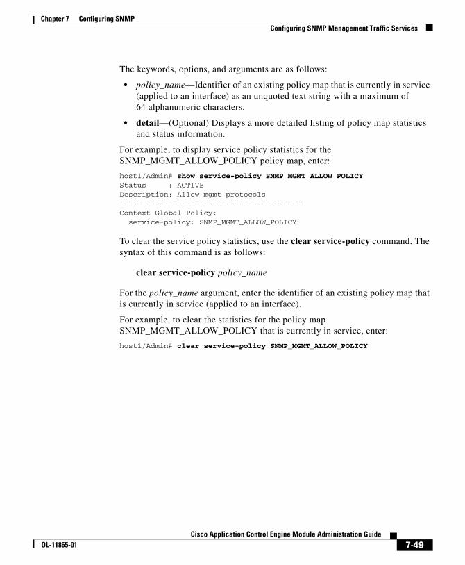
Chapter 7 Configuring SNMPConfiguring SNMP Management Traffic Services
The keywords, options, and arguments are as follows:
• policy_name—Identifier of an existing policy map that is currently in service (applied to an interface) as an unquoted text string with a maximum of 64 alphanumeric characters.
• detail—(Optional) Displays a more detailed listing of policy map statistics and status information.
For example, to display service policy statistics for the SNMP_MGMT_ALLOW_POLICY policy map, enter:
host1/Admin# show service-policy SNMP_MGMT_ALLOW_POLICYStatus : ACTIVEDescription: Allow mgmt protocols-----------------------------------------Context Global Policy: service-policy: SNMP_MGMT_ALLOW_POLICY
To clear the service policy statistics, use the clear service-policy command. The syntax of this command is as follows:
clear service-policy policy_name
For the policy_name argument, enter the identifier of an existing policy map that is currently in service (applied to an interface).
For example, to clear the statistics for the policy map SNMP_MGMT_ALLOW_POLICY that is currently in service, enter:
host1/Admin# clear service-policy SNMP_MGMT_ALLOW_POLICY
7-49Cisco Application Control Engine Module Administration Guide
OL-11865-01
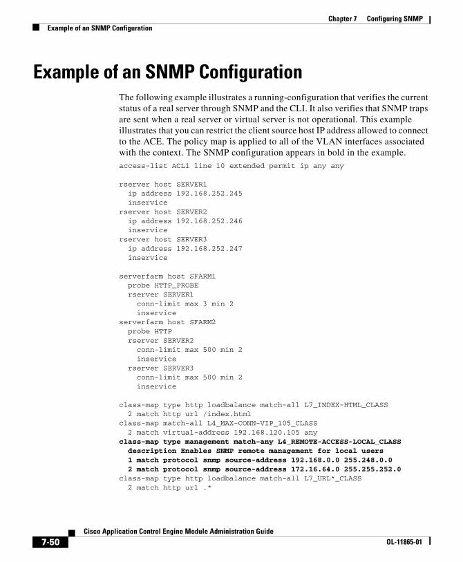
Chapter 7 Configuring SNMPExample of an SNMP Configuration
Example of an SNMP ConfigurationThe following example illustrates a running-configuration that verifies the current status of a real server through SNMP and the CLI. It also verifies that SNMP traps are sent when a real server or virtual server is not operational. This example illustrates that you can restrict the client source host IP address allowed to connect to the ACE. The policy map is applied to all of the VLAN interfaces associated with the context. The SNMP configuration appears in bold in the example.access-list ACL1 line 10 extended permit ip any any
rserver host SERVER1 ip address 192.168.252.245 inservicerserver host SERVER2 ip address 192.168.252.246 inservicerserver host SERVER3 ip address 192.168.252.247 inservice
serverfarm host SFARM1 probe HTTP_PROBE rserver SERVER1 conn-limit max 3 min 2 inserviceserverfarm host SFARM2 probe HTTP rserver SERVER2 conn-limit max 500 min 2 inservice rserver SERVER3 conn-limit max 500 min 2 inservice
class-map type http loadbalance match-all L7_INDEX-HTML_CLASS 2 match http url /index.htmlclass-map match-all L4_MAX-CONN-VIP_105_CLASS 2 match virtual-address 192.168.120.105 anyclass-map type management match-any L4_REMOTE-ACCESS-LOCAL_CLASS description Enables SNMP remote management for local users 1 match protocol snmp source-address 192.168.0.0 255.248.0.0 2 match protocol snmp source-address 172.16.64.0 255.255.252.0class-map type http loadbalance match-all L7_URL*_CLASS 2 match http url .*
7-50Cisco Application Control Engine Module Administration Guide
OL-11865-01
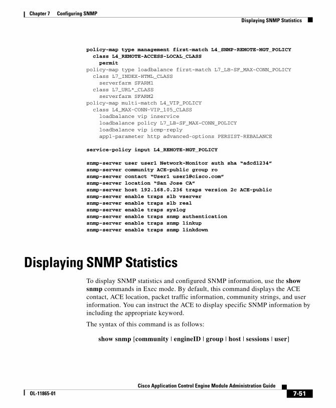
Chapter 7 Configuring SNMPDisplaying SNMP Statistics
policy-map type management first-match L4_SNMP-REMOTE-MGT_POLICY class L4_REMOTE-ACCESS-LOCAL_CLASS permitpolicy-map type loadbalance first-match L7_LB-SF_MAX-CONN_POLICY class L7_INDEX-HTML_CLASS serverfarm SFARM1 class L7_URL*_CLASS serverfarm SFARM2policy-map multi-match L4_VIP_POLICY class L4_MAX-CONN-VIP_105_CLASS loadbalance vip inservice loadbalance policy L7_LB-SF_MAX-CONN_POLICY loadbalance vip icmp-reply appl-parameter http advanced-options PERSIST-REBALANCE
service-policy input L4_REMOTE-MGT_POLICY
snmp-server user user1 Network-Monitor auth sha “adcd1234”snmp-server community ACE-public group rosnmp-server contact “User1 [email protected]”snmp-server location “San Jose CA”snmp-server host 192.168.0.236 traps version 2c ACE-public snmp-server enable traps slb vserversnmp-server enable traps slb realsnmp-server enable traps syslog snmp-server enable traps snmp authenticationsnmp-server enable traps snmp linkupsnmp-server enable traps snmp linkdown
Displaying SNMP StatisticsTo display SNMP statistics and configured SNMP information, use the show snmp commands in Exec mode. By default, this command displays the ACE contact, ACE location, packet traffic information, community strings, and user information. You can instruct the ACE to display specific SNMP information by including the appropriate keyword.
The syntax of this command is as follows:
show snmp [community | engineID | group | host | sessions | user]
7-51Cisco Application Control Engine Module Administration Guide
OL-11865-01
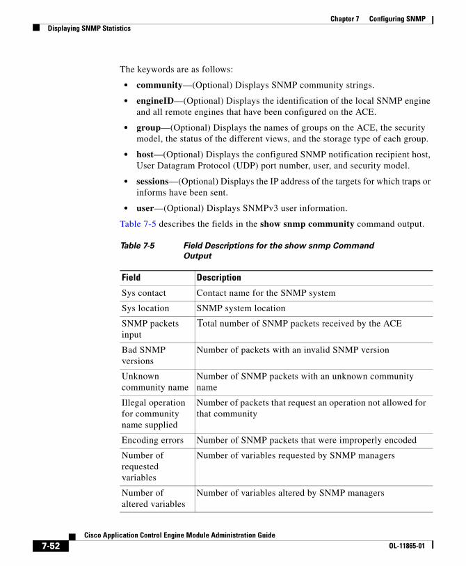
Chapter 7 Configuring SNMPDisplaying SNMP Statistics
The keywords are as follows:
• community—(Optional) Displays SNMP community strings.
• engineID—(Optional) Displays the identification of the local SNMP engine and all remote engines that have been configured on the ACE.
• group—(Optional) Displays the names of groups on the ACE, the security model, the status of the different views, and the storage type of each group.
• host—(Optional) Displays the configured SNMP notification recipient host, User Datagram Protocol (UDP) port number, user, and security model.
• sessions—(Optional) Displays the IP address of the targets for which traps or informs have been sent.
• user—(Optional) Displays SNMPv3 user information.
Table 7-5 describes the fields in the show snmp community command output.
Table 7-5 Field Descriptions for the show snmp Command
Output
Field Description
Sys contact Contact name for the SNMP system
Sys location SNMP system location
SNMP packets input
Total number of SNMP packets received by the ACE
Bad SNMP versions
Number of packets with an invalid SNMP version
Unknown community name
Number of SNMP packets with an unknown community name
Illegal operation for community name supplied
Number of packets that request an operation not allowed for that community
Encoding errors Number of SNMP packets that were improperly encoded
Number of requested variables
Number of variables requested by SNMP managers
Number of altered variables
Number of variables altered by SNMP managers
7-52Cisco Application Control Engine Module Administration Guide
OL-11865-01
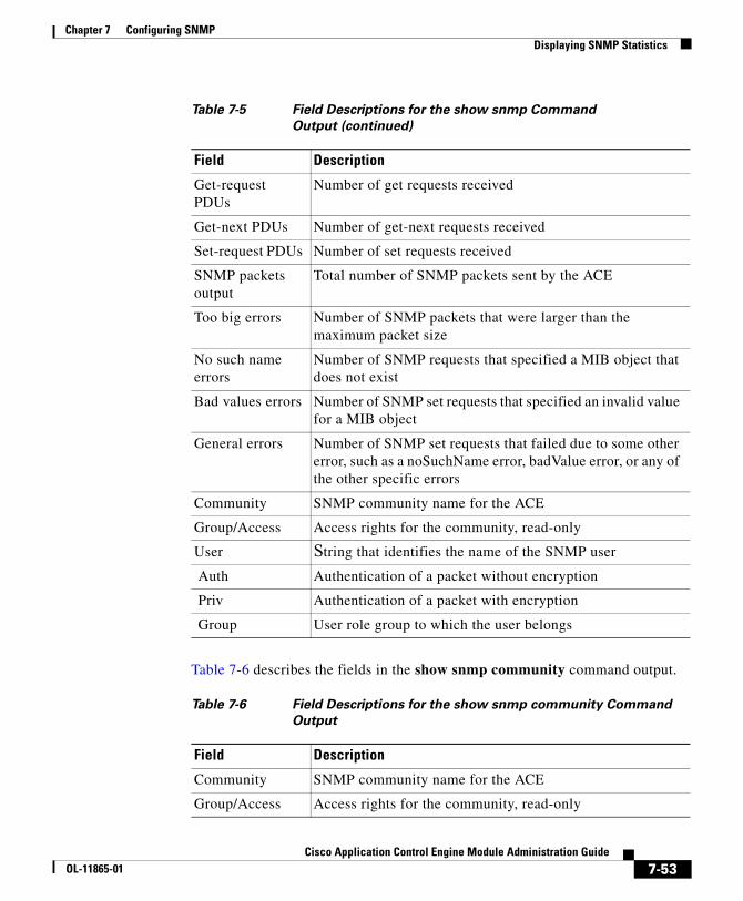
Chapter 7 Configuring SNMPDisplaying SNMP Statistics
Table 7-6 describes the fields in the show snmp community command output.
Get-request PDUs
Number of get requests received
Get-next PDUs Number of get-next requests received
Set-request PDUs Number of set requests received
SNMP packets output
Total number of SNMP packets sent by the ACE
Too big errors Number of SNMP packets that were larger than the maximum packet size
No such name errors
Number of SNMP requests that specified a MIB object that does not exist
Bad values errors Number of SNMP set requests that specified an invalid value for a MIB object
General errors Number of SNMP set requests that failed due to some other error, such as a noSuchName error, badValue error, or any of the other specific errors
Community SNMP community name for the ACE
Group/Access Access rights for the community, read-only
User String that identifies the name of the SNMP user Auth Authentication of a packet without encryption
Priv Authentication of a packet with encryption
Group User role group to which the user belongs
Table 7-5 Field Descriptions for the show snmp Command
Output (continued)
Field Description
Table 7-6 Field Descriptions for the show snmp community Command
Output
Field Description
Community SNMP community name for the ACE
Group/Access Access rights for the community, read-only
7-53Cisco Application Control Engine Module Administration Guide
OL-11865-01
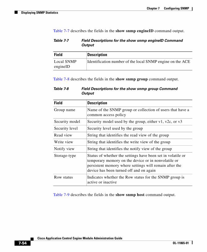
Chapter 7 Configuring SNMPDisplaying SNMP Statistics
Table 7-7 describes the fields in the show snmp engineID command output.
Table 7-8 describes the fields in the show snmp group command output.
Table 7-9 describes the fields in the show snmp host command output.
Table 7-7 Field Descriptions for the show snmp engineID Command
Output
Field Description
Local SNMP engineID
Identification number of the local SNMP engine on the ACE
Table 7-8 Field Descriptions for the show snmp group Command
Output
Field Description
Group name Name of the SNMP group or collection of users that have a common access policy
Security model Security model used by the group, either v1, v2c, or v3
Security level Security level used by the group
Read view String that identifies the read view of the group
Write view String that identifies the write view of the group
Notify view String that identifies the notify view of the group
Storage-type Status of whether the settings have been set in volatile or temporary memory on the device or in nonvolatile or persistent memory where settings will remain after the device has been turned off and on again
Row status Indicates whether the Row status for the SNMP group is active or inactive
7-54Cisco Application Control Engine Module Administration Guide
OL-11865-01
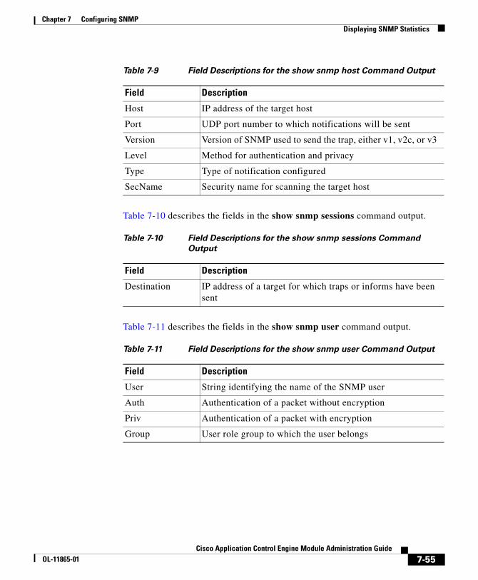
Chapter 7 Configuring SNMPDisplaying SNMP Statistics
Table 7-10 describes the fields in the show snmp sessions command output.
Table 7-11 describes the fields in the show snmp user command output.
Table 7-9 Field Descriptions for the show snmp host Command Output
Field Description
Host IP address of the target host
Port UDP port number to which notifications will be sent
Version Version of SNMP used to send the trap, either v1, v2c, or v3
Level Method for authentication and privacy
Type Type of notification configured
SecName Security name for scanning the target host
Table 7-10 Field Descriptions for the show snmp sessions Command
Output
Field Description
Destination IP address of a target for which traps or informs have been sent
Table 7-11 Field Descriptions for the show snmp user Command Output
Field Description
User String identifying the name of the SNMP user
Auth Authentication of a packet without encryption
Priv Authentication of a packet with encryption
Group User role group to which the user belongs
7-55Cisco Application Control Engine Module Administration Guide
OL-11865-01

Chapter 7 Configuring SNMPDisplaying SNMP Statistics
7-56Cisco Application Control Engine Module Administration Guide
OL-11865-01