AN INTRODUCTION TO THEORY. WHAT IS THEORY? Theory = Explanation.

Experiments for damage detection by subspaceidentification on real mechanical structures
Armin Lenzen, Leipzig University of Applied Sciences, Germany
Carsten Ebert, Leipzig University of Applied Sciences, Germany
Abstract
If structures of civil engineering are planned for a finite life time, it is advisable to control thebuildings for failures continuous such as by a monitoring system. In this lecture it is proposed toidentify the dynamic characteristics of a structure by vibration measurements. In the case of damagethis characteristic will be alternated. Here state space models are used to detect and localise systemvariations. State space models identified by the measurement data represent the transfer functionbetween input and output. The model parameters (e.g. Markov-Blocs) can be used for damagedetection.
Results from experimental measurements in our laboratory on a bending beam will show that themethods are able to localize damages. Furthermore experiments on a prestressed concrete tied-arch bridge in Hunxe (Germany) will be presented. The bridge had a span of 62.5 meters and wasdeconstructed in 2005. Preliminary numerous experiments were accomplished including two systemvariations. The first experiment for system variation was anadditional support near the bridge bearingof one main girder. During a further experiment one hanger from one tied arch was cut as an induceddamage.
1 Introduction
For hundreds of years builders and engineers have designed technical engines and buildings. Theessential load-bearing capacity and the fitness for purposehad to be guaranteed. Risen requirementsof economy and more exact mathematical models led to more slight structures in the last decades.Nevertheless damages and serious accidents can occur. To avoid this it would be desirable to monitorfamous buildings and engines over there life time. For monitoring different methods can be used.One possibility is to analyse vibration measurements. Numerous articles can be found which usemodal data for damage detection or model updating of finite element models (see [3] and [5]).
In this paper we present a method to extract physical interpretable parameters from a identified statespace model which can detect and localize changes of the mechanical properties of the measuredstructure.
2 State space model for mechanical systems
Typical mechanical structures are characterised through continuous mass and stiffness. To describethe dynamic properties of such structures partial differential equations can be used. For the numericprocessing by digital computers a discretization is neccessary. This can be done for example by

finite element method. From the mechanical equlilibrium conditions the equation of motion can bearranged:
Mxt + Dxt + Kxt = ut (1)
This second order differential equation can be transfered in a system of first order differential equa-tions by introduction the velocities as derivation of the displacements. Both mechanical parameterswill be merged in the state space vector z,
xt = vt (2)
xt = vt = −M−1Dvt − M−1Kxt + M−1ut (3)
or summarised in matrix notation:[
xt
vt
]
=
[
0 I
−M−1K −M−1D
]
[
xt
vt
]
+
[
0
M−1ut
]
(4)
Written as well known state space formulation follows:
zt = Azt + But (5)
yt = Czt + Dut (6)
The state matrices for linear mechanical systems are then:
A =
[
0 I
−M−1K −M−1D
]
B =
[
0
M−1
]
C =[
I 0
]
; D = 0
(7)
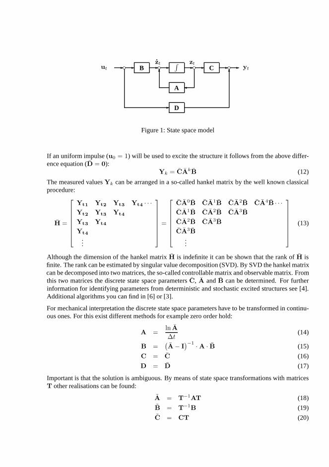
This state space system (equation (5) and (6)) describes thetransfer behavior of a linear mechanicalsystem. For linear models the system matricies are constantover time. In figure 2 you can see thatthe input will be transfered to the output by the state space system, remind that
y(s) = H(s)u(s) (8)
= C(sI − A)−1Bu(s) (9)
3 Identification of state space models
To detect changes of the mechanical properties of structures by vibration measurement you canidentify state space models. In section 2 we have shown the possibility to build a state space modelfrom the mechanical equation of motion. By experiments the measured values are simply avalible atdiscrete locations and time steps. For mathematical modelling a discrete state space formulation isused:
zk+1 = Azk + Buk (10)
yk = Czk + Duk (11)
�
- - -66
-- ---
-
c cc B∫
C
A
D
c ytut
zt zt
Figure 1: State space model
If an uniform impulse (u0 = 1) will be used to excite the structure it follows from the above differ-ence equation (D = 0):
Yk = CAkB (12)
The measured valuesYk can be arranged in a so-called hankel matrix by the well knownclassicalprocedure:
H =
Yt1 Yt2 Yt3 Yt4 · · ·
Yt2 Yt3 Yt4
Yt3 Yt4
Yt4
...
=
CA0B CA1B CA2B CA4B · · ·
CA1B CA2B CA3B
CA2B CA3B
CA3B
...
(13)
Although the dimension of the hankel matrixH is indefinite it can be shown that the rank ofH isfinite. The rank can be estimated by singular value decomposition (SVD). By SVD the hankel matrixcan be decomposed into two matrices, the so-called controllable matrix and observable matrix. Fromthis two matrices the discrete state space parametersC, A andB can be determined. For furtherinformation for identifying parameters from deterministic and stochastic excited structures see [4].Additional algorithms you can find in [6] or [3].
For mechanical interpretation the discrete state space parameters have to be transformed in continu-ous ones. For this exist different methods for example zero order hold:
A =ln A
∆t(14)
B =(
A− I)
−1· A · B (15)
C = C (16)
D = D (17)
Important is that the solution is ambiguous. By means of state space transformations with matricesT other realisations can be found:
A = T−1AT (18)
B = T−1B (19)
C = CT (20)

Because of this the searched mechanical parameters mass, stiffnes or damping can not be found in theidentified state space system directly (described in equation 7). In opposite to this are the productsof the state space parametersC, A and B (so-called markov parameters) unique and physicallyinterpretable .
If you inverse the system matrixA
A−1 =
[
−K−1D −K−1M
I 0
]
(21)
and multiply the parameters from equation (7) and (21) it follows:
CdAB = M−1 (22)
CdA−1B = −F = −K−1 (23)
The equations (22) and (23) describe the possibility to extract mass and stiffness matrices from astate space model. If measured datas are simulated with the aid of finite element models (see section2) the original mass and stiffness matrices can be identified. At real experiments this is more difficult.Some differences between theory and experiment are described in the next section.
3.1 Some remarks between differences of theory and experime nt
The theory for the state space model in section 2 based on displacement data. For experimentsnormaly velocity or acceleration sensors will be used. Whenmeasurement datas based on velocitiesor accelerations the identified model can be transfered in a displacement based model by integratingonce or twice respectively through multiplication ofA−1 (see [1]):
Cd = CvA−1 = CaA
−2 (24)
For identification of state space parameters (section 3) onecan excite the mechanical systems byuniform impulses. At experiments it is impossible to createan impulse with theoretical demandedproperties . The created impact will always have a finite duration and will never be infinite. Theambition for experiments is to create very short impacts that excites the structures. On the struc-ture applied sensors predefine the measured degrees of freedom. To get mechanical interpretablequadratic markov blocks it is possible to excite the structures on all sensor locations. Then for sub-space identification of the state-space model all measurment datas have to be arranged in a commonhankel matrix. For this step a common start point for all measurments has to be appointed. Mostlythe determination of this unique start point is not unambiguous. Based on the hankel matrix con-taining all measurements the time-discret state space parameters will be estimated. For mechanicalinterpretation these time-discret parameters must be transformed to time-continous parameters. Thistransformation can possibly cause numerical problems. Additionally all measurement datas containnoise.
If one has a look at the theoretical mechanical formulation it becomes clear that in theory the physicalsystem matrices (mass, stiffness and damping) are symmetric. This symmetry is produced from theMaxwell’s reciprocal theorem that describes the permutability between action and reaction. Becauseof this the markov parametersCAkB are also symmetric in theory and simulations. Even on exper-iments in laboratory it is exceedingly difficult to get thesesymmetry. Some causes that lead to thisare named in the text above. In succession the identified markov parameters are nonsymmetric and
the equations (22) and (23) don’t apply exactly. Nevertheless the inversion of the markov parameters(CdAB)−1 and(CdA
−1B)−1 are used in this paper for detection of system variances which areinduced by damages.
4 Experiments
4.1 Cantilever bending beam
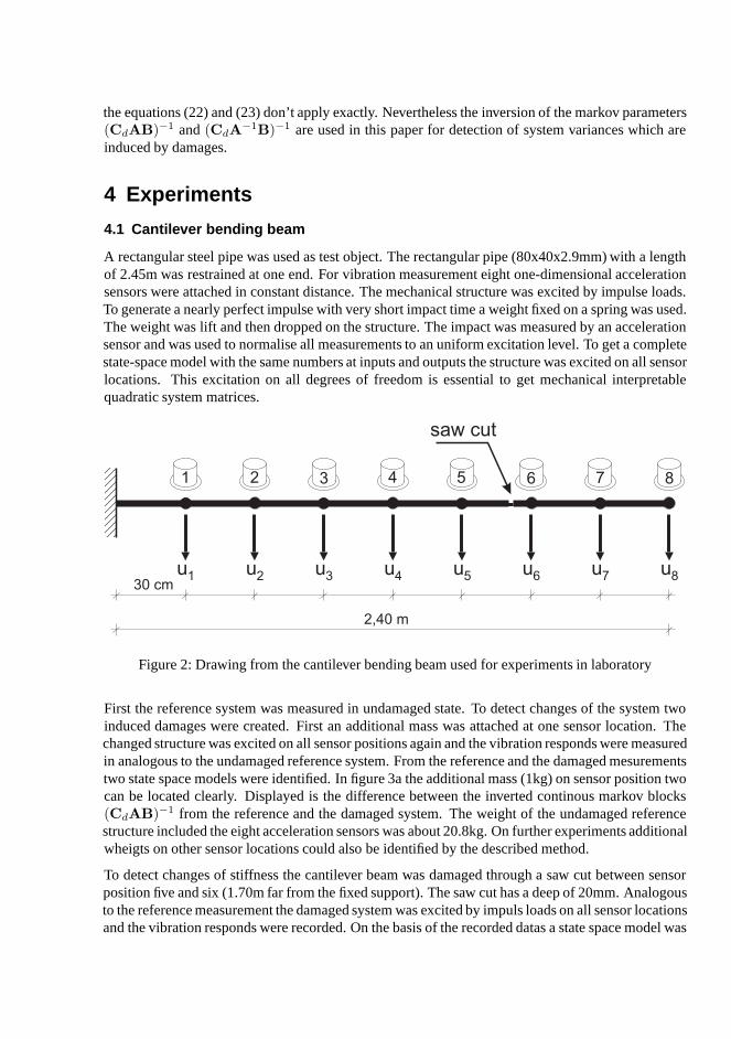
A rectangular steel pipe was used as test object. The rectangular pipe (80x40x2.9mm) with a lengthof 2.45m was restrained at one end. For vibration measurement eight one-dimensional accelerationsensors were attached in constant distance. The mechanicalstructure was excited by impulse loads.To generate a nearly perfect impulse with very short impact time a weight fixed on a spring was used.The weight was lift and then dropped on the structure. The impact was measured by an accelerationsensor and was used to normalise all measurements to an uniform excitation level. To get a completestate-space model with the same numbers at inputs and outputs the structure was excited on all sensorlocations. This excitation on all degrees of freedom is essential to get mechanical interpretablequadratic system matrices.
1 2 3 4 5 6 7 8
30 cm
2,40 m
u u u u u u u u1 2 3 4 5 6 7 8
saw cut
Figure 2: Drawing from the cantilever bending beam used for experiments in laboratory
First the reference system was measured in undamaged state.To detect changes of the system twoinduced damages were created. First an additional mass was attached at one sensor location. Thechanged structure was excited on all sensor positions againand the vibration responds were measuredin analogous to the undamaged reference system. From the reference and the damaged mesurementstwo state space models were identified. In figure 3a the additional mass (1kg) on sensor position twocan be located clearly. Displayed is the difference betweenthe inverted continous markov blocks(CdAB)−1 from the reference and the damaged system. The weight of the undamaged referencestructure included the eight acceleration sensors was about 20.8kg. On further experiments additionalwheigts on other sensor locations could also be identified bythe described method.
To detect changes of stiffness the cantilever beam was damaged through a saw cut between sensorposition five and six (1.70m far from the fixed support). The saw cut has a deep of 20mm. Analogousto the reference measurement the damaged system was excitedby impuls loads on all sensor locationsand the vibration responds were recorded. On the basis of therecorded datas a state space model was

identified. In figure 3b the differences between the invertedcontinous markov blocks(CdA−1B)−1
from the reference and the damaged system are displayed. Thesaw cut near sensor position six canbe identified clearly.
0 1 2 3 4 5 6 7 8−0.3
−0.2
−0.1
0
0.1
0.2
0.3
0.4
differences of inverse markov blocks : (CAB)reference−1 − (CAB)
damage−1
DOF
(a) Additional mass (1kg) at DOF 2
0 1 2 3 4 5 6 7 8−3
−2.5
−2
−1.5
−1
−0.5
0
0.5
1x 10⁷
DOF
differences of inverse markov blocks: (CA−1B)−1reference
− (CA−1B)−1damage
(b) Saw cut (20mm) at DOF 6
Figure 3: Markov blocks for damage detection
4.2 Tied-arch bridge near Hunxe - Germany
Near Hunxe (Germany) a tied-arch bridge with a span of 62.5m(Fig. 4) was deconstructed in2005 because of corrosion. The bridge was built in 1952 in order to lead a country road acrossthe Wesel-Datteln-Canal. Main- and cross-girder, track-slab and the hanger consisted of prestressedconcrete, the arch was built in reinforced concrete. On the verge of deconstruction it was possible
Figure 4: Bridge near Hunxe / Germany (span: 62.5m)
to accomplish numerous vibration measurements. For the experiments two damaged states wereinduced. First an additional support near the bridge bearing of one main girder was set-up. In a

second experiment one hanger from one tied arch was cut through. For the different experiments thebridge was excited through deterministic (by impulse hammer) and stochastic (by traffic, wind, etc.)loads. The used special constructed impulse hammer has a moveable weight of 150kg and was fixedon the bridge near the sensor points. The moveable weight wasadvanced by a pneumatic system. Atimpact a acceleration of 1000 m/s2 was measured.The available measurement system could handlesixteen acceleration sensors. Only the vertical acceleration of the two main girders were measured.First the actuel condition of the bridge was measured individual for all excitations. With this datasstate space models of the reference condition were identified. Afterwards the damaged conditionswere measured and identified.
4.2.1 System variation through cut hanger
Before the deconstruction of the bridge took place one of thetwenty hangers was cut through. Thethird hanger on south-west side was selected because of static rules for the following deconstrutctionof the whole bridge. The cross-section of the prestressed concrete hanger varies over the heightfrom about 55x50cm down to 35x30cm upside. After this induced damage vibration measurementswith deterministic (impulse) and stochastic (traffic, wind) excitation took place analogously to thereference measurements.
The measured modes identified by the
Figure 5: System modification: hanger cut through
system transfer function (eq. 8) shouldbe shown as first step for damage lo-calization here. For lack of space onlyone mode should be introduced here.At the example of the 10th mode (fig-ure 6) it is possible to see the changeof the system by the generated dam-age clearly. The undamaged referencesystem has one torsional mode withfive maxima (16.11 Hz). After thefailure of the hanger two global tor-sional modes (5 maxima) can be iden-tified with clearly changed frequenciesin each case (15.66 and 17.28 Hz).The modes have their most essentialchange of amplitude in the area of the
damage. The same results were achieved by a finite element model of the structure that was builtto check the plausibility of the measurement results. Othermodes show also significant changes infrequencies and shapes. Especially higher modes can identify local damages as you can see in theexperiment with cut hanger. In a further experiment an additional support near the bridge bearingof one main girder was set-up. For this global damage lower modes (especially the first one) iden-tify the system variation (further informations in [2]). Intense research is ongoing to extract furthermechanical interpretable parameters (e.g. markov parameters) for damage localization on this realmeasured tied-arch bridge.

(a) damaged hanger - mode 10a (b) damaged hanger - mode 10b
(c) reference system
Figure 6: Torsional mode from reference system and after cuthanger
5 Conclusion
In this article a method is described that can identify changes of mechanical structures on the basisof vibration measurements. Initially a mathematical statespace model will be identified by subspacemethod that describe the transfer behaviour of the measuredmechanical structure. It can be showntheoretically how characteristic system matrices like mass and stiffness can be extrated from suchstate space models. Extensive differences between theory and real measured experiments produceproblems that prevent the direct estimation of mass and stiffness matrices. From the theory divergenteffects arises in particular from not ideal impulse loads, absence of symmetry (Maxwell’s reciprocaltheorem), non-linear shares and measurement noise.
On a cantilever bending beam we could accomplish numerous vibration measurments for undamagedand damaged states in our laboratory. Different damage states were measured such as additionalweights on single sensors positions or saw cuts between two sensors. The structure - a steel rectanglepipe - was excited by impulse loads on all degrees of freedom.For these real experiments it couldbe shown that products of the identified state space matricesC, A andB (the so-called markovparameters) are able to locate discret changes of masses andstiffness clearly.
During a furhter experimental test on a wide-span prestressed-concrete tied arch bridge the presentedprocedures were used for system identification. Two system modifications should show the potentialof the algorithm to identify and locate damages. Intense research is ongoing to extract mechanicalinterpretable parameters direct from the identified state space model.
Acknowledgements: The work described in this paper was funded by the Deutsche Forschungsge-meinschaft (DFG). The financial support is gratefully acknowledged. Furthermore we gratefullyacknowledge the valuable assistance provided by the waterway administration - WSA - Duisburg -Meiderich, Germany, Ernst Corinth and Holger Leukel - the owner of the bridge near Hunxe.
6 References
[1] K. F. Alvin, A. N. Robertson, G. W. Reich, and K. C. Park. Structural system identification:from reality to models.Computers & Structures, Volume 81, Issue 12:Pages 1149–1176, 2003.
[2] Carsten Ebert and Armin Lenzen. Output-only analysis for experimental damage detection of atied-arch bridge. In17th Int. Conf. on the Application of Computer Science and Mathematics inArchitecture and Civil Engineering, number ISSN 1611-4086, Weimar, 2006.
[3] M.I. Friswell and J.E. Mottershead].Finite element updating in structural dynamics. KluwerAcademic Publishers Group, 1995.
[4] Armin Lenzen. Identification of mechanical systems by vibration analysis for health monitoringand damage detection. In N. Møller R. Brinker, editor,1st International Operational ModalAnalysis Conference, 2005.
[5] Michael Link. Using complex modes for model updating of structures with non-proportionaldamping. InProc. of the International Conference on Noise and Vibration Engineering(ISMA2006). University of Leuven, Belgium, 2006.
[6] Peter van Overschee and Bart L. R. de Moor.Subspace identification for linear systems: theory,implementation, applications. Kluwer Academic Publishers Group, 1996.